Crafstman CMXEDCG471 El manual del propietario
- Categoría
- Abridor de puerta de garage
- Tipo
- El manual del propietario
Este manual también es adecuado para

Owner's Manual
GARAGE DOOR OPENER
For Residential Use Only
MODEL CMXEOCG231
READ AND FOLLOW ALL SAFETY RULES AND OPERATING INSTRUCTIONS BEFORE FIRST USE OF THIS PRODUCT.
FASTEN THE MANUAL NEAR THE GARAGE DOOR AFTER INSTALLATION.
PERIODIC CHECKS OF THE OPENER ARE REQUIRED TO ENSURE SAFE OPERATION.
DO NOT INSTALL ON A ONE-PIECE DOOR IF USING DEVICES OR FEATURES PROVIDING UNATTENDED CLOSE.
UNATTENDED DEVICES AND FEATURES ARE TO BE USED ONLY WITH SECTIONAL DOORS. SEE PAGE 3.
WWW.CRAFTSMAN.COM

2
INTRODUCTION 2-7
Safety Symbol Review and Signal Word Review . . . . . . . . . . . . . . . . . . . . . . . . . . . .2
Unattended Operation. . . . . . . . . . . . . . . . . . . . . . . . . . . . . . . . . . . . . . . . . . . . . . . .3
Preparing your Garage Door . . . . . . . . . . . . . . . . . . . . . . . . . . . . . . . . . . . . . . . . . . .3
Tools Needed. . . . . . . . . . . . . . . . . . . . . . . . . . . . . . . . . . . . . . . . . . . . . . . . . . . . . . .3
Planning . . . . . . . . . . . . . . . . . . . . . . . . . . . . . . . . . . . . . . . . . . . . . . . . . . . . . . . 4-5
Carton Inventory . . . . . . . . . . . . . . . . . . . . . . . . . . . . . . . . . . . . . . . . . . . . . . . . . . . .6
Hardware Inventory . . . . . . . . . . . . . . . . . . . . . . . . . . . . . . . . . . . . . . . . . . . . . . . . . .7
ASSEMBLY 8-11
Assemble the Rail and Install the Trolley . . . . . . . . . . . . . . . . . . . . . . . . . . . . . . . . .8
Fasten the Rail to the Motor Unit . . . . . . . . . . . . . . . . . . . . . . . . . . . . . . . . . . . . . . .8
Install the Idler Pulley. . . . . . . . . . . . . . . . . . . . . . . . . . . . . . . . . . . . . . . . . . . . . . . .9
Install the Chain/Cable. . . . . . . . . . . . . . . . . . . . . . . . . . . . . . . . . . . . . . . . . . . . . .10
Tighten the Chain . . . . . . . . . . . . . . . . . . . . . . . . . . . . . . . . . . . . . . . . . . . . . . . . . .11
INSTALLATION 11-27
Installation Safety Instructions. . . . . . . . . . . . . . . . . . . . . . . . . . . . . . . . . . . . . . . .11
Determine the Header Bracket Location . . . . . . . . . . . . . . . . . . . . . . . . . . . . . . . . .12
Install the Header Bracket . . . . . . . . . . . . . . . . . . . . . . . . . . . . . . . . . . . . . . . . . . .13
Attach the Rail to the Header Bracket . . . . . . . . . . . . . . . . . . . . . . . . . . . . . . . . . .14
Position the Opener. . . . . . . . . . . . . . . . . . . . . . . . . . . . . . . . . . . . . . . . . . . . . . . . .15
Hang the Opener . . . . . . . . . . . . . . . . . . . . . . . . . . . . . . . . . . . . . . . . . . . . . . . . . . .16
Install the Light . . . . . . . . . . . . . . . . . . . . . . . . . . . . . . . . . . . . . . . . . . . . . . . . . . .17
Attach the Emergency Release Rope and Handle . . . . . . . . . . . . . . . . . . . . . . . . . .17
Fasten the Door Bracket . . . . . . . . . . . . . . . . . . . . . . . . . . . . . . . . . . . . . . . . . . 18-19
Connect Door Arm to Trolley . . . . . . . . . . . . . . . . . . . . . . . . . . . . . . . . . . . . . . . 20-21
Attach the Warning Labels . . . . . . . . . . . . . . . . . . . . . . . . . . . . . . . . . . . . . . . . . . .21
Install the Door Control. . . . . . . . . . . . . . . . . . . . . . . . . . . . . . . . . . . . . . . . . . . . . .22
Install the Safety Reversal System . . . . . . . . . . . . . . . . . . . . . . . . . . . . . . . . . . 23-25
Electrical Requirements . . . . . . . . . . . . . . . . . . . . . . . . . . . . . . . . . . . . . . . . . . . . .26
Aligning the Safety Reversing Sensors . . . . . . . . . . . . . . . . . . . . . . . . . . . . . . . . . .27
ADJUSTMENT 28-30
Introduction. . . . . . . . . . . . . . . . . . . . . . . . . . . . . . . . . . . . . . . . . . . . . . . . . . . . . . .28
Program the Travel . . . . . . . . . . . . . . . . . . . . . . . . . . . . . . . . . . . . . . . . . . . . . . . . .29
Test the Safety Reversal System . . . . . . . . . . . . . . . . . . . . . . . . . . . . . . . . . . . . . . .30
Test the Safety Reversing Sensors . . . . . . . . . . . . . . . . . . . . . . . . . . . . . . . . . . . . .30
OPERATION 31-35
Important safety instructions . . . . . . . . . . . . . . . . . . . . . . . . . . . . . . . . . . . . . . . . .31
Features . . . . . . . . . . . . . . . . . . . . . . . . . . . . . . . . . . . . . . . . . . . . . . . . . . . . . . . . .32
Using Your Garage Door Opener . . . . . . . . . . . . . . . . . . . . . . . . . . . . . . . . . . . . . . .32
Using the Door Control . . . . . . . . . . . . . . . . . . . . . . . . . . . . . . . . . . . . . . . . . . . . . .32
Remote Control . . . . . . . . . . . . . . . . . . . . . . . . . . . . . . . . . . . . . . . . . . . . . . . . . . . .33
To Erase the Memory. . . . . . . . . . . . . . . . . . . . . . . . . . . . . . . . . . . . . . . . . . . . . . . .33
To Open the Door Manually . . . . . . . . . . . . . . . . . . . . . . . . . . . . . . . . . . . . . . . . . . .34
Care of Your Opener . . . . . . . . . . . . . . . . . . . . . . . . . . . . . . . . . . . . . . . . . . . . . . . .34
TROUBLESHOOTING 35-36
REPAIR PARTS 37-38
Rail Assembly Parts . . . . . . . . . . . . . . . . . . . . . . . . . . . . . . . . . . . . . . . . . . . . . . . .37
Installation Parts . . . . . . . . . . . . . . . . . . . . . . . . . . . . . . . . . . . . . . . . . . . . . . . . . .37
Motor Unit Assembly Parts . . . . . . . . . . . . . . . . . . . . . . . . . . . . . . . . . . . . . . . . . . .38
ACCESSORIES 39
WARRANTY 39
AUTOMATIC GARAGE DOOR OPENER SAFETY &
MAINTENANCE GUIDE 40-41
TABLE OF CONTENTS
When you see these Safety Symbols and Signal Words on the following pages, they
will alert you to the possibility of serious injury or death if you do not comply with
the warnings that accompany them. The hazard may come from something
mechanical or from electric shock. Read the warnings carefully.
When you see this Signal Word on the following pages, it will alert you to the
possibility of damage to your garage door and/or the garage door opener if you do
not comply with the cautionary statements that accompany it. Read them carefully.
INTRODUCTION
SAFETY SYMBOL AND SIGNAL WORD REVIEW
This garage door opener has been designed and tested to offer safe service provided it is installed, operated, maintained and tested in strict accordance with the
instructions and warnings contained in this manual.
Mechanical
Electrical
WARNING: This product can expose you to chemicals including
lead, which are known to the State of California to cause cancer or
birth defects or other reproductive harm. For more information go to
www.P65Warnings.ca.gov.

UNATTENDED OPERATION
Any device or feature that allows the door to close without being in the line of sight of the door is considered unattended close. Devices that allow unattended operation
are to be used ONLY with sectional doors.
PREPARING YOUR GARAGE DOOR
Before you begin:
1. Disable locks and remove any ropes connected to the garage door.
2. Lift the door halfway up. Release the door. If balanced, it should stay in
place, supported entirely by its springs.
3. Raise and lower the door to check for binding or sticking. If your door
binds, sticks, or is out of balance, call a trained door systems technician.
4. Check the seal on the bottom of the door. Any gap between the floor and
the bottom of the door must not exceed 1/4" (6mm). Otherwise, the safety
reversal system may not work properly.
5. The opener should be installed above the center of the door. If there is a
torsion spring or center bearing plate in the way of the header bracket, it
may be installed within 4feet (1.2 m) to the left or right of the door center.
See page12.
Sectional Door One-Piece Door
To prevent possible SERIOUSINJURYor DEATH:
l ALWAYS call a trained door systems technician if garage door binds, sticks,
or is out of balance. An unbalanced garage door may NOT reverse when
required.
l NEVER try to loosen, move or adjust garage door, door springs, cables,
pulleys, brackets or their hardware, ALLof which are under EXTREME
tension.
l Disable ALLlocks and remove ALLropes connected to garage door BEFORE
installation and operating garage door opener to avoid entanglement.
l DO NOT install on a one-piece door if using devices or features providing
unattended close. Unattended devices and features are to be used ONLY
with sectional doors.
To prevent damage to garage door and opener:
l ALWAYS disable locks BEFORE installing and operating the opener.
l ONLY operate garage door opener at 120V, 60Hz to avoid malfunction and
damage.
TOOLS NEEDED
During assembly, installation and adjustment of the opener, instructions will call for hand tools as illustrated below.
Stepladder
Drill Bits 3/16",
5/16", and 5/32"
Claw Hammer
Carpenter’s Level
(optional)
Pencil
Screwdriver
Drill
Wire Cutters
Adjustable End Wrench
Tape Measure
Pliers
Sockets and Wrench 1/2",
5/8", 7/16", 9/16", and 1/4"
Hack Saw
3

PLANNING
Identify the type and height of your garage door. Survey your garage area to see if
any of the conditions below apply to your installation. Additional materials may be
required. You may find it helpful to refer back to this page and the accompanying
illustrations as you proceed with the installation of your opener. Depending on
your requirements, there are several installation steps which may call for
materials or hardware not included in the carton.
l Installation Step 1 – Look at the wall or ceiling above the garage door.
The header bracket must be securely fastened to structural supports.
l Installation Step 5 – Do you have a finished ceiling in your garage? If
so, a support bracket and additional fastening hardware may be
required.
l Installation Step 12 – Depending upon garage construction, extension
brackets or wood blocks may be needed to install sensors.
l Installation Step 12 – Alternate floor mounting of the safety reversing
sensor will require hardware not provided.
l Do you have an access door in addition to the garage door? If not, an
emergency key release is required.
l Look at the garage door where it meets the floor. Any gap between the
floor and the bottom of the door must not exceed 1/4" (6 mm).
Otherwise, the safety reversal system may not work properly. See
Adjustment Step 2. Floor or door should be repaired.
SECTIONAL DOOR INSTALLATION
l Do you have a steel, aluminum, fiberglass or glass panel door? If so,
horizontal and vertical reinforcement is required (Installation Step 8).
l The opener should be installed above the center of the door. If there is a
torsion spring or center bearing plate in the way of the header bracket, it
may be installed within 4 feet (1.22 m) to the left or right of the door
center. See Installation Steps 1 and 8.
l If your door is more than 7 feet (2.13 m) high, see rail extension kits
listed on Accessories page.
Safety Reversing Sensor
Header Wall
Access Door
Safety Reversing
Sensor
Gap between floor
and bottom of door
must not exceed 1/4" (6 mm).
Extension Spring
Horizontal and vertical reinforcement
is needed for lightweight garage doors
(fiberglass, steel, aluminum, door with
glass panels, etc.). See page 18 for details.
Support bracket &
fastening hardware
is required.
See page 16.
FINISHED CEILING
Motor unit
Wall-mounted
Door Control
OR
Torsion Spring
Slack in chain tension
is normal when garage
door is closed.
Vertical
Centerline
of Garage
Door
Emergency
Release Rope
& Handle
Straight
Door
Arm
Garage
Door
Spring
Door
Bracket
Header
Bracket
Garage
Door
Header
Wall
CLOSED POSITION
Rail Tab
Curved
Door Arm
Chain
Trolley
SECTIONAL DOOR INSTALLATION
4

PLANNING (CONTINUED)
ONE-PIECE DOOR INSTALLATIONS
l Generally, a one-piece door does not require reinforcement. If your door is
lightweight, refer to the information relating to sectional doors in
Installation Step 8.
l Depending on your door’s construction, you may need additional mounting
hardware for the door bracket (Installation Step 8).
Without a properly installed safety reversing sensor, persons (particularly small
children) could be SERIOUSLY INJURED or KILLED by a closing garage door.
l The gap between the bottom of the garage door and the floor MUST NOT
exceed 1/4" (6 mm). Otherwise, the safety reversal system may NOT work
properly.
l The floor or the garage door MUST be repaired to eliminate the gap.
Safety Reversing Sensor
Access
Door
FINISHED CEILING
Support bracket
and fastening
hardware is required.
See page 16.
Safety Reversing
Sensor
Header Wall
Gap between floor
and bottom of door must
not exceed 1/4" (6 mm).
Wall-mounted
Door Control
Rail
Motor Unit
Slack in chain tension
is normal when garage
door is closed.
Access
Door
Safety Reversing Sensor
Safety Reversing Sensor
Gap between floor and bottom of door must
not exceed 1/4" (6 mm).
Header
Bracket
Straight
Door
Arm
Emergency
Release
Rope & Handle
Door Bracket
Curved
Door
Arm
Header
Wall
Cable
Rail
Garage Door
CLOSED POSITION
Rail Tab
Straight Door
Arm
Curved
Door Arm
Door
Bracket
Header
Bracket
Garage
Door
Header
Wall
CLOSED POSITION
Rail Tab
Chain
Rail
Cable
ONE-PIECE DOOR WITHOUT TRACK
ONE-PIECE DOOR WITH TRACK
5

CARTON INVENTORY
Your garage door opener is packaged in one carton which contains the motor unit
and all parts illustrated below. Accessories will depend on the model purchased.
If anything is missing, carefully check the packing material.
Hardware for assembly and installation is shown on the next page. Save the
carton and packing material until installation and adjustment is complete.
Straight Door
Arm Section
Curved Door
Arm Section
Safety Labels
and
Literature
2-Conductor Bell Wire
White & White/Red
Idler Pulley
001A5295
Chain and Cable
Hanging Brackets
(2) Safety Reversing Sensors
(1 Sending Sensor and 1 Receiving Sensor)
with 2-Conductor White & White/Black
Bell Wire attached
Door Bracket
Trolley
Safety Sensor
Bracket (2)
Rail
Center/Back
Sections
"U" Bracket
Rail
Front (header)
Section
Header Bracket
Chain Spreader
Motor Unit with a Light Lens
Door Control
3-Button Remote Control
6

HARDWARE INVENTORY
Separate all hardware and group as shown below for the assembly and installation procedures.
Wing Nut
1/4"-20 (2)
133A0196
Carriage Bolt
1/4"-20x1/2" (2)
171A0191
Handle
091B0019-1
Nut 5/16"-18 (6)
133A0028
Ring
Fastener (3)
158A0047
Insulated Staples
(Not shown)
131A0031
Drywall Anchors (2)
133A0126
Clevis Pin
5/16"x1"
146A0058
Rope
Lock Washer 5/16" (5)
216A0025
Lag Screw
5/16"-9x1-5/8" (4)
171A0480
Hex Bolt
5/16"-18x7/8" (4)
171A0301
Clevis Pin
5/16"x1-1/4"
146A0074
Screw
6ABx1" (2)
171A0361
Screw 6-32x1" (2)
171A0475
Clevis Pin
5/16"x1-1/2"
1460100
Self-Threading Screw
1/4"-14x5/8" (2)
171A0540
INSTALLATION HARDWARE
ASSEMBLY HARDWARE
Master
Link (2)
Idler Bolt
Nut 3/8"
Trolley Threaded Shaft
Lock Washer 3/8"
Lock Nut
1/4"-20
Bolt
1/4"-20x1-3/4"
7

ASSEMBLY STEP 1
ASSEMBLE THE RAIL AND INSTALL THE TROLLEY
To avoid installation difficulties, do not run the garage door opener until
instructed to do so.
The front rail has a cut out “window” at the door end. The front rail has a rail
tab. This tab MUST be on the top of the rail when assembled.
1. Remove the straight door arm and hanging bracket packaged inside
the front rail and set aside for Installation Step 5 and 9. NOTE: To
prevent INJURY while unpacking the rail carefully remove the straight
door arm stored within the rail section.
2. Align the rail sections on a flat surface as shown and slide the
tapered ends into the larger ones. Tabs along the side will lock into
place.
3. Place the motor unit on packing material to protect the cover, and
rest the back end of the rail on top. For convenience, put a support
under the front end of the rail.
4. As a temporary stop, insert a screwdriver into the hole 10" (25 cm)
from the front end of the rail, as shown.
5. Check to be sure there are 4 plastic wear pads inside the inner
trolley. If they became loose during shipping, check all packing
material. Snap them back into position as shown.
6. Slide the trolley assembly along the rail from the back end to the
screwdriver.
7. Slide the rail onto the “U” bracket, until it reaches all the stops on
the top and sides of the “U” bracket.
To prevent INJURY from pinching, keep hands and fingers away from the joints
while assembling the rail.
To garage
door opener
(TO MOTOR UNIT)
“U” Bracket
Outer Trolley
Inner Trolley
Wear Pads
SLIDE TO STOPS
ON TOP AND
SIDES OF
“U” BRACKET
Front Rail
Section
(TO DOOR)
Rail
Tab
Trolley
Window
Cut-Out
Idler
Pulley
Hole
ASSEMBLY STEP 2
FASTEN THE RAIL TO THE MOTOR UNIT
1. Insert a 1/4"-20 x 2-1/2" bolt into the cover protection bolt hole on the
back end of the rail as shown. Tighten securely with a 1/4"-20 lock nut. DO
NOT overtighten.
2. Remove the bolts from the top of the motor unit.
3. Use the carton to support the front end of the rail.
4. Place the “U” bracket, flat side down onto the motor unit and align the
bracket holes with the bolt holes.
5. Fasten the “U” bracket with the previously removed bolts; DO NOT use any
power tools. The use of power tools may permanently damage the garage
door opener.
6. Attach chain spreader to the motor unit with two screws.
HARDWARE SHOWN ACTUAL SIZE
Bolt
1/4"-20x1-3/4"
Lock Nut
1/4"-20
To avoid SERIOUS damage to garage door opener, use ONLY those
bolts/fasteners mounted in the top of the opener.
Bolt
“U” Bracket
Hex Screws
8-32x7/16"
Chain
Spreader
Cover
Protection
Bolt Hole
Lock Nut
1/4"-20
Bolt
8

ASSEMBLY STEP 3
INSTALL THE IDLER PULLEY
1. Lay the chain/cable beside the rail, as shown. Grasp the end of the cable
and pass approximately 12" (30 cm) of cable through the window. Allow it
to hang until Assembly Step4.
2. Remove the tape from the idler pulley. The inside center should be pre-
greased. If dry, regrease to ensure proper operation.
3. Place the idler pulley into the window as shown.
4. Insert the idler bolt from the top through the rail and pulley. Tighten with
a 3/8" lock washer and nut underneath the rail until the lock washer is
compressed.
5. Rotate the pulley to be sure it spins freely.
6. Locate the rail tab. The rail tab is near the idler pulley on the front rail
section. Use a flat head screwdriver and lift the rail tab until the tab is
vertical (90º).
Lock
Washer
3/8"
Idler Bolt
Rail Tab
Idler Pulley
Screwdriver
CORRECT
INCORRECT
Chain and Cable
Cable Link
Rail Tab
Nut 3/8"
Idler Bolt
HARDWARE SHOWN ACTUAL SIZE
Trolley
Lock Washer 3/8"
Nut 3/8"
9

ASSEMBLY STEP 4
INSTALL THE CHAIN/CABLE
1. Pull the cable around the idler pulley and toward the trolley.
2. Connect the cable to the retaining slot on the trolley, as shown. (Figure1)
a. From below, push pins of master link bar up through cable link
and trolley slot.
b. Push master link cap over pins and past pin notches.
c. Slide clip-on spring over cap and onto pin notches until both
pins are securely locked in place.
3. With the trolley against the screwdriver, dispense the remainder of the
cable/chain along the rail toward the motor unit around the sprocket and
continuing to the trolley assembly. The sprocket teeth must engage the
chain. (Figure2)
4. Check to make sure the chain is not twisted, then connect it to the
threaded shaft with the remaining master link.
5. Thread the inner nut and lock washer onto the trolley threaded shaft.
6. Insert the trolley threaded shaft through the hole in the trolley. Be sure
the chain is not twisted. (Figure3)
7. Loosely thread the outer nut onto the trolley threaded shaft.
8. Remove the screwdriver.
To avoid possible SERIOUS INJURY to finger from moving garage door opener:
l ALWAYS keep hand clear of sprocket while operating opener.
l Securely attach sprocket cover BEFORE operating.
10
Sprocket
Leave Chain and Cable
Inside Bag to
Prevent Kinking.
Master Link
Nut 5/16"-18
Trolley Threaded Shaft
Lock Washer 5/16"
HARDWARE SHOWN ACTUAL SIZE
Figure 2
Figure 1
Keep Chain and Cable
Taut When Dispensing
Master Link
Threaded Shaft
Outer Nut
Master Link
Inner Nut
Lock Washer
Figure 3

ASSEMBLY STEP 5
TIGHTEN THE CHAIN
1. Spin the inner nut and lock washer down the trolley threaded shaft, away
from the trolley.
2. To tighten the chain, turn the outer nut in the direction shown (Figure1).
3. When the chain is approximately 1/4" (6 mm) above the base of the rail at
it's midpoint, re-tighten the inner nut to secure the adjustment (Figure2).
Sprocket noise can result if chain is too loose. When installation is complete, you
may notice some chain droop with the door closed. This is normal. If the chain
returns to the position shown in Figure2 when the door is open, do not re-adjust
the chain.
NOTES:
l During future maintenance, ALWAYS pull the emergency release handle to
disconnect the trolley before adjusting the chain.
l You may notice loosening of chain after Adjustment Step2 (Test the
Safety Reversal System). Check for proper tension and readjust chain if
necessary. Then repeat Adjustment Step2.
You have now finished assembling your garage door opener. Please read the
following warnings before proceeding to the installation section.
Figure 1
Figure 2
Base of Rail
Mid Length of Rail
Chain
1/4" (6 mm)
Outer
Nut
Lock
Washer
Trolley
Threaded
Shaft
Inner Nut
To Tighten
Inner Nut
To Tighten Outer Nut
INSTALLATION
IMPORTANT INSTALLATION INSTRUCTIONS
To reduce the risk of SEVERE INJURY or DEATH:
1. READ AND FOLLOW ALL INSTALLATION WARNINGS AND INSTRUCTIONS.
2. Install garage door opener ONLY on properly balanced and lubricated garage
door. An improperly balanced door may NOT reverse when required and could
result in SEVERE INJURY or DEATH.
3. ALL repairs to cables, spring assemblies and other hardware MUST be made
by a trained door systems technician BEFORE installing opener.
4. Disable ALL locks and remove ALL ropes connected to garage door BEFORE
installing opener to avoid entanglement.
5. Where possible, install the door opener 7 feet (2.13 m) or more above the
floor.
6. Mount the emergency release within reach, but at least 6 feet (1.83 m) above
the floor and avoiding contact with vehicles to avoid accidental release.
7. NEVER connect garage door opener to power source until instructed to do so.
8. NEVER wear watches, rings or loose clothing while installing or servicing
opener. They could be caught in garage door or opener mechanisms.
9. Install wall-mounted garage door control:
l within sight of the garage door.
l out of reach of small children at a minimum height of 5feet
(1.5m) above floors, landings, steps or any other adjacent walking
surface.
l away from ALL moving parts of the door.
10. Place entrapment warning label on wall next to garage door control in a
prominent location.
11. Place emergency release/safety reverse test label in plain view on inside of
garage door.
12. Upon completion of installation, test safety reversal system. Door MUST
reverse on contact with a 1-1/2" (3.8cm) high object (or a 2x4 laid flat) on
the floor.
13. DO NOT install on a one-piece door if using devices or features providing
unattended close. Unattended devices and features are to be used ONLY with
sectional doors.
11

INSTALLATION STEP 1
DETERMINE THE HEADER BRACKET LOCATION
To prevent possible SERIOUS INJURY or DEATH:
l Header bracket MUST be RIGIDLY fastened to structural support on header
wall or ceiling, otherwise garage door might NOT reverse when required.
DO NOT install header bracket over drywall.
l Concrete anchors MUST be used if mounting header bracket or 2x4 into
masonry.
l NEVER try to loosen, move or adjust garage door, springs, cables,
pulleys, brackets, or their hardware, ALL of which are under EXTREME
tension.
l ALWAYS call a trained door systems technician if garage door binds,
sticks, or is out of balance. An unbalanced garage door might NOT
reverse when required.
Installation procedures vary according to garage door types. Follow the instructions
which apply to your door.
1. Close the door and mark the inside vertical centerline of the garage door.
2. Extend the line onto the header wall above the door. You can fasten the
header bracket within 4 feet (1.22 m) of the left or right of the door
center only if a torsion spring or center bearing plate is in the way; or
you can attach it to the ceiling (see page 13) when clearance is minimal.
(It may be mounted on the wall upside down if necessary, to gain
approximately 1/2" (1 cm). If you need to install the header bracket on a
2x4 (on wall or ceiling), use lag screws (not provided) to securely fasten
the 2x4 to structural supports as shown here and on page 13.
3. Open your door to the highest point of travel as shown. Draw an
intersecting horizontal line on the header wall above the high point:
l 2" (5 cm) above the high point for sectional door and one-piece door with
track.
l 8" (20 cm) above the high point for one-piece door without track.
This height will provide travel clearance for the top edge of the door.
NOTE: If the total number of inches exceeds the height available in your garage,
use the maximum height possible, or refer to page13 for ceiling installation.
Header Wall
Vertical Centerline
of Garage Door
Level
(optional)
2x4
2x4
Structural
Supports
Unfinished
Ceiling
OPTIONAL
CEILING
MOUNT
FOR
HEADER
BRACKET
Door
Jamb
Hardware
Header Wall
Highest Point
of Travel
Door
2" (5 cm)
Door
Track
Header Wall
Highest Point
of Travel
2" (5 cm)
8" (20 cm)
Highest
Point
of Travel
Door
Pivot
8" (20 cm)
Highest
Point
of Travel
Header Wall
Header Wall
Track
One-piece door with horizontal track
One-piece door without track:
jamb hardware
One-piece door without track:
pivot hardware
Sectional door with curved track
12

INSTALLATION STEP 2
INSTALL THE HEADER BRACKET
You can attach the header bracket either to the wall above the garage door, or to
the ceiling. Follow the instructions which will work best for your particular
requirements. Do not install the header bracket over drywall. If installing into
masonry, use concrete anchors (not provided).
WALL HEADER BRACKET INSTALLATION
1. Center the bracket on the vertical centerline with the bottom edge of the
bracket on the horizontal line as shown (with the arrow pointing toward
the ceiling).
2. Mark the vertical set of bracket holes. Drill 3/16" pilot holes and fasten
the bracket securely to a structural support with the hardware provided.
CEILING HEADER BRACKET INSTALLATION
1. Extend the vertical centerline onto the ceiling as shown.
2. Center the bracket on the vertical mark, no more than 6" (15cm) from the
wall. Make sure the arrow is pointing away from the wall. The bracket
can be mounted flush against the ceiling when clearance is minimal.
3. Mark the side holes. Drill 3/16" pilot holes and fasten bracket securely to
a structural support with the hardware provided.
Lag Screw
5/16"-9x1-5/8"
HARDWARE SHOWN ACTUAL SIZE
Lag Screws
5/16"-9x1-5/8"
Highest Point of
Garage Door Travel
Vertical
Centerline
of Garage Door
Door Spring
2x4
Structural
Support
Vertical
Centerline
of Garage Door
Header
Bracket
Horizontal
Line
Lag Screws
5/16"-9x1-5/8"
Door
Spring
6" (15 cm) Maximum
Header
Bracket
Vertical
Centerline
of Garage Door
Garage Door
Vertical Centerline
of Garage Door
UP
Wall Mount
Optional
Mounting Holes
UP
Ceiling Mounting Holes
Figure 1
Figure 2
Header Wall
Header Wall
Finished Ceiling
Garage Door
13

INSTALLATION STEP 3
ATTACH THE RAIL TO THE HEADER BRACKET
1. Position the opener on the garage floor below the header bracket. Use
packing material as a protective base.
NOTE: If the door spring is in the way, you will need help. Have someone
hold the opener securely on a temporary support to allow the rail to clear
the spring.
2. Position the rail bracket against the header bracket.
3. Align the bracket holes and join with a clevis pin as shown.
4. Insert a ring fastener to secure.
Temporary
Support
Garage
Door
Header Bracket
Idler Pulley
Header Wall
Clevis Pin 5/16"x1-1/2"
Ring Fastener
Header
Bracket
Mounting
Hole
HARDWARE SHOWN ACTUAL SIZE
14

INSTALLATION STEP 4
POSITION THE OPENER
Follow instructions which apply to your door type as illustrated.
SECTIONAL DOOR OR ONE-PIECE DOOR WITH TRACK
A 2x4 laid flat is convenient for setting an ideal door-to-rail distance.
1. Raise the opener onto a stepladder. You will need help at this point if the
ladder is not tall enough.
2. Open the door all the way and place a 2x4 laid flat on the top section
beneath the rail (Figure 1).
3. If the top section or panel hits the trolley when you raise the door, pull
down on the trolley release arm to disconnect inner and outer sections.
Slide the outer trolley toward the motor unit. The trolley can remain
disconnected until Installation Step 12 is completed.
ENGAGED
RELEASED
Trolley
Release Arm
ONE-PIECE DOOR WITHOUT TRACK
A 2x4 on its side is convenient for setting an ideal door-to-rail distance.
1. Raise the opener onto a stepladder. You will need help at this point if the
ladder is not tall enough.
2. Open the door all the way and place a 2x4 on its side on the top section
of the door beneath the rail (Figure 2).
3. The top of the door should be level with the top of the motor unit. Do not
position the opener more than 4" (10 cm) above this point.
To prevent damage to garage door, rest garage door opener rail on 2x4 placed
on top section of door.
Header
Bracket
Top of Door
2x4 is used to determine
the correct mounting height
from ceiling.
Rail
2x4 is used to determine
the correct mounting height
from ceiling.
Door
Figure 1
Figure 2
15

INSTALLATION STEP 5
HANG THE OPENER
To avoid possible SERIOUS INJURY from a falling garage door opener, fasten it
SECURELY to structural supports of the garage. Concrete anchors MUST be
used if installing ANY brackets into masonry.
Three representative installations are shown. Yours may be different. Hanging
brackets should be angled (Figure 1) to provide rigid support. On finished ceilings
(Figures 2 and 3), attach a sturdy metal bracket to structural supports before
installing the opener. This bracket and fastening hardware are not provided.
1. Measure the distance from each side of the motor unit to the structural
support.
2. Cut both pieces of the hanging bracket to required lengths.
3. Drill 3/16" pilot holes in the structural supports.
4. Attach one end of each bracket to a support with 5/16"-9x1-5/8" lag
screws.
5. Fasten the opener to the hanging brackets with 5/16"-18x7/8" hex bolts,
lock washers and nuts.
6. Check to make sure the rail is centered over the door (or in line with the
header bracket if the bracket is not centered above the door).
7. Remove the 2x4. Operate the door manually. If the door hits the rail, raise
the header bracket.
NOTE: DO NOT connect power to opener at this time.
Lag Screw 5/16"-9x1-5/8"
Hex Bolt
5/16"-18x7/8"
Nut 5/16"-18
Lock Washer 5/16"
HARDWARE SHOWN ACTUAL SIZE
Measure
Distance
Lag Screw
5/16"-9x1-5/8"
Structural
Supports
Bracket
(Not Provided)
Lag Screw
5/16"-9x1-5/8"
Hidden
Support
Hex Bolt 5/16"-18x7/8"
Lock Washer 5/16"
Nut 5/16"-18
(Not Provided)
Hex Bolt 5/16"-18x7/8"
Lock Washer 5/16"
Nut 5/16"-18
FINISHED CEILING
Hex Bolt 5/16"-18x7/8"
Lock Washer 5/16"
Nut 5/16"-18
Hex Bolt 5/16"-18x7/8"
Lock Washer 5/16"
Nut 5/16"-18
Lag Screw
5/16"-9x1-5/8"
FINISHED CEILING
(Not Provided)
Hex Bolt 5/16"-18x7/8"
Lock Washer 5/16"
Nut 5/16"-18
Figure 1
Figure 2
Figure 3
16

INSTALLATION STEP 6
INSTALL THE LIGHT
1. Press the release tabs on both sides of lens. Gently rotate lens back and
downward until the lens hinge is in the fully open position. Do not remove
the lens.
2. Insert an A19 incandescent (100 watt maximum) or compact fluorescent
(26W, 100W equivalent) light bulb into the light socket. The lights will turn
ON and remain lit for approximately 4-1/2 minutes when power is
connected. Then the lights will turn OFF.
3. Reverse the procedure to close the lens.
4. If the bulb burns out prematurely due to vibration, replace with a garage
door opener bulb. Use A19, standard neck garage door opener bulb for
replacement.
NOTE: Do not use halogen, short neck, or specialty light bulbs as these may
overheat the end panel or light socket. Do not use LED bulbs as they may reduce the
range or performance of your remote control(s).
To prevent possible OVERHEATING of the end panel or light socket:
l Use ONLY A19 incandescent (100W maximum) or compact fluorescent (26W
maximum) light bulbs.
l DO NOT use incandescent bulbs larger than 100W.
l DO NOT use compact fluorescent light bulbs larger than 26W (100W
equivalent).
l DO NOT use halogen bulbs.
l DO NOT use short neck or specialty light bulbs.
Lens
Hinge
Release Tab
100 Watt (Max)
Standard Light Bulb
INSTALLATION STEP 7
ATTACH THE EMERGENCY RELEASE ROPE AND HANDLE
1. Insert one end of the emergency release rope through the handle. Make
sure that “NOTICE” is right side up. Secure with an overhand knot at least
1" (2.5 cm) from the end of the rope to prevent slipping.
2. Insert the other end of the emergency release rope through the hole in the
trolley release arm. Mount the emergency release within reach, but at least
6 feet (1.83m) above floor, avoiding contact with vehicles to prevent
accidental release and secure with an overhand knot.
NOTE: If it is necessary to cut the emergency release rope, seal the cut end with a
match or lighter to prevent unraveling. Ensure the emergency release rope and
handle are above the top of all vehicles to avoid entanglement.
To prevent possible SERIOUS INJURY or DEATH from a falling garage door:
l If possible, use emergency release handle to disengage trolley ONLY when
garage door is CLOSED. Weak or broken springs or unbalanced door could
result in an open door falling rapidly and/or unexpectedly.
l NEVER use emergency release handle unless garage doorway is clear of
persons and obstructions.
l NEVER use handle to pull door open or closed. If rope knot becomes untied,
you could fall.
Trolley
Release Arm
Emergency
Release Handle
Overhand
Knot
Trolley
17

INSTALLATION STEP 8
FASTEN THE DOOR BRACKET
Follow instructions which apply to your door type as illustrated below or on the
following page.
A horizontal reinforcement brace should be long enough to be secured to two or
three vertical supports. A vertical reinforcement brace should cover the height of
the top panel.
Figure 1 shows one piece of angle iron as the horizontal brace. For the vertical
brace, 2 pieces of angle iron are used to create a U-shaped support. The best
solution is to check with your garage door manufacturer for an opener installation
door reinforcement kit.
NOTE: Many door reinforcement kits provide for direct attachment of the clevis pin
and door arm. In this case you will not need the door bracket; proceed to Step 9.
SECTIONAL DOORS
1. Center the door bracket on the previously marked vertical centerline used
for the header bracket installation. Note correct UP placement, as
stamped inside the bracket.
2. Position the top edge of the bracket 2"-4" (5-10cm) below the top edge
of the door, OR directly below any structural support across the top of the
door.
3. Mark, drill holes and install as follows, depending on your door’s
construction.
Metal or light weight doors using a vertical angle iron brace between the door
panel support and the door bracket:
l Drill 3/16" fastening holes. Secure the door bracket using the two 1/4"-
14x5/8" self-threading screws. (Figure2A)
l Alternately, use two 5/16"-18x2" bolts, lock washers and nuts (not
provided). (Figure2B)
Metal, insulated or light weight factory reinforced doors:
l Drill 3/16" fastening holes. Secure the door bracket using the self-
threading screws. (Figure3)
Wood doors:
l Use top and bottom or side to side door bracket holes. Drill 5/16" holes
through the door and secure bracket with 5/16"-18x2" carriage bolts, lock
washers and nuts (not provided). (Figure4)
NOTE: The 1/4"-14x5/8" self-threading screws are not intended for use on wood
doors.
Self-Threading
Screw
1/4"-14x5/8"
HARDWARE
SHOWN ACTUAL
SIZE
Fiberglass, aluminum or lightweight steel garage doors WILL REQUIRE
reinforcement BEFORE installation of door bracket. Contact the garage door
manufacturer or installing dealer for opener reinforcement instructions or
reinforcement kit.
Figure 1
Door Bracket
Vertical Centerline
of Garage Door
Vertical Reinforcement
Self-Threading
Screw 1/4"-14x5/8"
UP
Figure 2A
Figure 2B
Bolt
(Not
Door
Bracket
Vertical Reinforcement
5/16"-18x2"
(Not
Provided)
Nut
5/16"-18
Lock Washer 5/16"
UP
Vertical
Centerline
of Garage Door
UP
Self-Threading Screw
1/4"-14x5/8"
Vertical
Centerline
of Garage Door
UP
Inside Edge
of Door or
Reinforcement Board
Bolt 5/16"-18x2"
(Not Provided)
Vertical
Centerline
of Garage
Door
Figure 3
Figure 4
Vertical
Centerline
of Garage
Door
Door
Bracket
Location
Header
Bracket
HORIZONTAL AND VERTICAL
REINFORCEMENT IS NEEDED FOR
LIGHTWEIGHT GARAGE DOORS
(FIBERGLASS, ALUMINUM, STEEL,
DOORS WITH GLASS PANEL, ETC.).
(NOT PROVIDED)
18

FASTEN THE DOOR BRACKET (CONTINUED)
ONE-PIECE DOORS
Please read and comply with the warnings and reinforcement instructions on the
previous page. They apply to one-piece doors also.
l Center the door bracket on the top of the door, in line with the header
bracket as shown. Mark either the left and right, or the top and bottom
holes.
l Metal Doors: Drill 3/16" pilot holes and fasten the bracket with the 1/4"-
14x5/8" self-threading screws provided.
l Wood Doors: Drill 5/16" holes and use 5/16"x2" carriage bolts, lock
washers and nuts (not provided) or 5/16"x1-1/2" lag screws (not provided)
depending on your installation needs.
NOTE: The door bracket may be installed on the top edge of the door if required for
your installation. (Refer to the dotted line optional placement drawing.)
Header Wall
Vertical
Centerline of
Garage Door
Optional
Placement
of Door
Bracket
Header
Bracket
Door
Bracket
2x4
Support
For a door with no exposed framing,
or for the optional installation, use
lag screws 5/16"x1-1/2" (Not Provided)
to fasten door bracket.
Top of Door
(Inside Garage)
Door
Bracket
Optional
Placement
Top Edge
of Door
Self-Threading
Screw
1/4"-14x5/8"
Door
Bracket
Top of Door
(Inside Garage)
Carriage Bolt
5/16"x2"
(Not Provided)
Optional
Placement
Lock
Washer
5/16"
Nut
5/16"-18
Top Edge
of Door
METAL DOOR
WOOD DOOR
HORIZONTAL AND VERTICAL
REINFORCEMENT IS NEEDED
FOR LIGHTWEIGHT GARAGE
DOORS (FIBERGLASS, ALUMINUM,
STEEL, DOORS WITH GLASS
PANEL, ETC.). (NOT PROVIDED)
Finished Ceiling
Self-Threading Screw
1/4"-14x5/8"
HARDWARE SHOWN
ACTUAL SIZE
19

INSTALLATION STEP 9
CONNECT DOOR ARM TO TROLLEY
Follow instructions which apply to your door type as illustrated below and on the
following page.
IMPORTANT: The groove on the straight door arm MUST face away from the curved
door arm (Figure 4).
SECTIONAL DOORS ONLY
1. Make sure garage door is fully closed. Pull the emergency release handle
to disconnect the outer trolley from the inner trolley. Slide the outer trolley
back (away from the pulley) about 8" (20 cm) as shown in Figures 1, 2 and
3.
2. Fasten straight door arm section to outer trolley with the 5/16"x1" clevis
pin. Secure the connection with a ring fastener (Figure 1).
3. Fasten curved section to the door bracket in the same way, using the
5/16"x1-1/4" clevis pin.
4. Bring arm sections together. Find two pairs of holes that line up and join
sections. Select holes as far apart as possible to increase door arm
rigidity (Figure 2).
Hole alignment alternative (Figure 3):
l If holes in curved arm are above holes in straight arm, disconnect straight
arm. Cut about 6" (15 cm) from the solid end. Reconnect to trolley with cut
end down as shown.
l Bring arm sections together.
l Find two pairs of holes that line up and join with bolts, lock washers and
nuts.
Pull the emergency release handle toward the opener at a 45° angle so that the
trolley release arm is horizontal. Trolley will re-engage automatically when opener
is operated during the adjustments.
Lock Washer 5/16"
Nut 5/16"-18
Ring Fastener
Hex Bolt
5/16"-18x7/8"
Clevis Pin
5/16"x1" (Trolley)
Clevis Pin
5/16"x1-1/4" (Door Bracket)
HARDWARE SHOWN ACTUAL SIZE
Ring
Fastener
Door
Bracket
Straight
Door Arm
Curved Door Arm
Inner
Trolley
Outer
Trolley
Lock
Washers
5/16"
Nuts
5/16"-18
Door Bracket
Hex Bolts
5/16"-18x7/8"
Cut this end
Emergency
Release
Handle
Lock
Washers
5/16"
Nuts
5/16"-18
Hex Bolts
5/16"-18x7/8"
Clevis Pin
5/16"x1"
Clevis Pin 5/16"x1-1/4"
Pulley
Pulley
Pulley
Figure 1
Figure 2
Figure 3
8" (20 cm) min.
8" (20 cm) min.
8" (20 cm) min.
Figure 4
CORRECT INCORRECT
Straight
Door Arm
Straight
Door Arm
Curved
Door Arm
Curved
Door
Arm
(Groove
facing out)
20

CONNECT DOOR ARM TO TROLLEY (CONTINUED)
ALL ONE-PIECE DOORS
IMPORTANT: The groove on the straight door arm MUST face away from the curved
door arm (Figure 5).
1. Close the door. Disconnect the trolley by pulling the emergency release
handle.
2. Fasten the straight door arm and the curved door arm together to the
longest possible length (with a 2 or 3 hole overlap) using the bolts, nuts,
and lock washers.
3. Attach the straight door arm to the door bracket using the 5/16"x1-1/4"
clevis pin. Secure with the ring fastener.
4. Attach the curved door arm to the trolley using the 5/16"x1" clevis pin.
Secure with the ring fastener.
5. Pull the emergency release handle toward the garage door opener until
the trolley release arm is horizontal.
Lock Washer 5/16"
Nut 5/16"-18
Ring Fastener
Hex Bolt
5/16"-18x7/8"
Clevis Pin
5/16"x1" (Trolley)
Clevis Pin
5/16"x1-1/4" (Door Bracket)
HARDWARE SHOWN ACTUAL SIZE
Figure 5
CORRECT INCORRECT
Straight
Door Arm
Straight
Door Arm
Curved
Door Arm
Curved
Door
Arm
(Groove
facing out)
Curved
Door Arm
Rail Tab
Ring
Fastener
Door
Bracket
Outer Trolley
Inner Trolley
Emergency
Release
Handle
Straight
Door
Arm
Pulley
Clevis Pin
5/16"x1-1/4"
Hex Bolts
5/16"-18x7/8"
Lock Washers
5/16"
Nuts
5/16"-18
Ring Fastener
Figure 6 One-Piece Door Without Track
Clevis Pin
5/16"x1"
Clevis Pin
5/16"x1"
Ring Fastener
Ring Fastener
Nuts 5/16"-18
Figure 7 One-Piece Door With Track
Lock Washers 5/16"
Clevis Pin
5/16"x1-1/4"
Hex Bolt 5/16"-18x7/8"
INSTALLATION STEP 10
ATTACH THE WARNING LABELS
1. Attach the entrapment warning label on the wall near the door control with
tacks or staples.
2. Attach the manual release/safety reverse test label in a visible location on
the inside of the garage door.
21

INSTALLATION STEP 11
INSTALL THE DOOR CONTROL
Install door control within sight of garage door, out of reach of small children at a
minimum height of 5 feet (1.5 m) above floors, landings, steps or any other
adjacent walking surface, and away from ALL moving parts of door. For gang box
installations it is not necessary to drill holes or install the drywall anchors. Use
the existing holes in the gang box.
NOTE: Your product may look different than the illustrations.
Screw
6ABx1" (2)
Drywall
Anchors (2)
Screw
6-32x1" (2)
HARDWARE
Screw
6ABx1-1/2" (2)
PUSH BUTTON DOOR CONTROL
1. Strip 1/4" (6 mm) of insulation from one end of the wire and separate the
wires.
2. Connect one wire to each of the two screws on the back of the door
control. The wires can be connected to either screw.
3. Mount the door control with the hardware provided.
1/4" (6 mm)
1 2 3
WIRE THE DOOR CONTROL TO THE GARAGE DOOR OPENER
1. Run the white and red/white wire from the door control to the garage door
opener. Attach the wire to the wall and ceiling with the staple (not
applicable for gang box or pre-wired installations). Do not pierce the wire
with the staple as this may cause a short or an open circuit.
2. Strip 7/16" (11 mm) of insulation from the end of the wire near the garage
door opener.
3. Connect the wire to the red and white terminals on the garage door
opener. If your garage is pre-wired make sure you use the same wires
that are connected to the door control. To insert or release wires from the
terminal, push in the tab with screwdriver tip.
RED
WHITE
WHITE
GREY
7/16" (11 mm)
2
3
1
HARDWARE
Insulated Staple (Not Shown)
Staple
To prevent possible SERIOUS INJURY or DEATH from electrocution:
l Be sure power is NOT connected BEFORE installing door control.
l Connect door control ONLY to 12 VOLT low voltage wires.
To prevent possible SERIOUS INJURY or DEATH from a closing garage door:
l Install door control within sight of garage door, out of reach of small
children at a minimum height of 5feet (1.5m) above floors, landings,
steps or any other adjacent walking surface, and away from ALL moving
parts of door.
l NEVER permit children to operate or play with door control push buttons or
remote control transmitters.
l Activate door ONLY when it can be seen clearly, is properly adjusted, and
there are no obstructions to door travel.
l ALWAYS keep garage door in sight until completely closed. NEVER permit
anyone to cross path of closing garage door.
22

INSTALLATION STEP 12
INSTALL THE SAFETY REVERSAL SYSTEM
IMPORTANT INFORMATION ABOUT THE SAFETY REVERSING SENSORS
The safety reversing sensors must be connected and aligned correctly before the
garage door opener will move in the down direction.
The sending sensor (with an amber LED) transmits an invisible light beam to the
receiving sensor (with a green LED). If an obstruction breaks the light beam while
the door is closing, the door will stop and reverse to the full open position, and the
garage door opener lights will flash 10 times.
NOTE: For energy efficiency the garage door opener will enter sleep mode when the
door is fully closed. The sleep mode shuts the garage door opener down until
activated. The sleep mode is sequenced with the garage door opener lights; as the
lights turns off, the sensor LEDs will turn off and whenever the garage door opener
lights turn on, the sensor LEDs will light. The garage door opener will not go into
the sleep mode until the garage door opener has completed 5 cycles upon power
up.
When installing the safety reversing sensors check the following:
l Sensors are installed inside the garage, one on either side of the door.
l Sensors are facing each other with the lenses aligned and the receiving
sensor lens does not receive direct sunlight.
l Sensors are no more than 6 inches (15 cm) above the floor and the light
beam is unobstructed.
Invisible Light Beam
Protection Area
Safety Reversing Sensor
6" (15 cm) max. above floor
Safety Reversing Sensor
6" (15 cm) max. above floor
Facing the door from inside the garage
Be sure power is NOT connected to the garage door opener BEFORE installing
the safety reversing sensor.
To prevent SERIOUS INJURY or DEATH from closing garage door:
l Correctly connect and align the safety reversing sensor. This required
safety device MUST NOT be disabled.
l Install the safety reversing sensor so beam is NO HIGHER than 6" (15 cm)
above garage floor.
23

INSTALL THE SAFETY REVERSAL SYSTEM (CONTINUED)
INSTALLING THE BRACKETS
Be sure power to the opener is disconnected. Install and align the brackets so the
sensors will face each other across the garage door, with the beam no higher than
6" (15 cm) above the floor. They may be installed in one of three ways, as follows.
Garage door track installation (preferred):
1. Slip the curved arms over the rounded edge of each door track, with the
curved arms facing the door. Snap into place against the side of the
track. It should lie flush, with the lip hugging the back edge of the track,
as shown in Figure 1.
If your door track will not support the bracket securely, wall installation is
recommended.
Wall installation (Figures 2 and 3):
1. Place the bracket against the wall with curved arms facing the door. Be
sure there is enough clearance for the sensor beam to be unobstructed.
2. If additional depth is needed, an extension bracket (see Accessories) or
wood blocks can be used.
3. Use bracket mounting holes as a template to locate and drill (2) 3/16"
diameter pilot holes on the wall at each side of the door, no higher than
6"(15cm) above the floor.
4. Attach brackets to wall with lag screws (not provided).
5. If using extension brackets or wood blocks, adjust right and left
assemblies to the same distance out from the mounting surface. Make
sure all door hardware obstructions are cleared.
Floor installation (Figure 4):
1. Use wood blocks or extension brackets (see Accessories) to elevate
sensor brackets so the lenses will be no higher than 6"(15cm) above
the floor.
2. Carefully measure and place right and left assemblies at the same
distance out from the wall. Be sure all door hardware obstructions are
cleared.
3. Fasten to the floor with concrete anchors as shown.
Indicator
Light
Lens
Lip
Door
Track
Indicator
Light
Lens
Extension Bracket
(See Accessories)
Inside
Garage
Wall
(Provided with
Extension Bracket)
(Provided with
Extension Bracket)
Attach with
Concrete Anchors
(Not provided)
Inside
Garage
Wall
Lens
Indicator
Light
Inside
Garage
Wall
Indicator
Light
Safety
Reversing
Sensor
Bracket
Safety
Reversing
Sensor
Bracket
Lens
Lag Screws
(Not provided)
Fasten Wood Block to Wall with
Lag Screws (Not provided)
Safety
Reversing
Sensor
Bracket
Safety
Reversing
Sensor
Bracket
Figure 1
DOOR TRACK MOUNT (RIGHT SIDE)
WALL MOUNT (RIGHT SIDE)
WALL MOUNT (RIGHT SIDE)
FLOOR MOUNT (RIGHT SIDE)
Figure 2
Figure 3
Figure 4
24

Figure 5
Figure 6
Figure 7
Figure 9
Figure 8
Carriage
Bolt
Wing
Nut
Safety Reversing
Sensor Wires
7/16"
(11 mm)
7/16"
(11 mm)
Pre-Installed Wires
Not Provided
Pre-Installed
Wires
Safety
Reversing
Sensor
Wires
White
White/Black
Safety Reversing
Sensor
Safety Reversing
Sensor
1. Strip wire 7/16" (11 mm)
7/16" (11 mm)
2. Twist like colored
wires together
3. To insert or release
wire, push in tab with
screwdriver tip
Quick-Connect Terminals
Red White Grey
Bell Wire
Bell Wire
Invisible Light Beam
Protection Area
Connect Wire to
Quick-Connect Terminals
Finished
Ceiling
Figure 10
INSTALL THE SAFETY REVERSAL SYSTEM (CONTINUED)
Wing Nut
1/4"-20
Insulated Staples
(Not Shown)
Carriage Bolt
1/4"-20x1/2"
HARDWARE SHOWN ACTUAL SIZE
MOUNTING AND WIRING THE SAFETY REVERSING SENSORS
Mounting:
1. Slide a 1/4"-20 x 1/2" carriage bolt head into the slot on each sensor. Use
wing nuts to fasten sensors to brackets, with lenses pointing toward
each other across the door. Be sure the lens is not obstructed by a
bracket extension (Figure 5).
2. Finger tighten the wing nuts.
Option A - Installation Without Pre-Wiring:
1. Run the bell wire from both sensors to the garage door opener. Attach the
wire to the wall and ceiling with the staples (Figure 6).
Option B - Pre-Wired Installation:
If your garage already has wires installed for the safety reversing sensors, follow
the instructions below:
1. Cut the end of the safety sensor wire, making sure there is enough wire
to reach the pre-installed wires from the wall (Figure 7).
2. Separate the safety sensor wires and strip 7/16" (11mm) of insulation
from each end. Choose two of the pre-installed wires and strip 7/16"
(11mm) of insulation from each end. Make sure that you choose the
same color pre-installed wires for each sensor (Figure 8).
3. Connect the pre-installed wires to the sensor wires with wire nuts
making sure the colors correspond for each sensor (Figure 9).
CONNECT TO GARAGE DOOR OPENER:
1. Strip 7/16" (11mm) of insulation from each set of wires. Separate white
and white/black wires sufficiently to connect to the opener quick-connect
terminals. Twist like colored wires together. Insert wires into quick-
connect holes: white to white and white/black to grey (Figure 10).
25

INSTALLATION STEP 13
ELECTRICAL REQUIREMENTS
To avoid installation difficulties, do not run the opener at this time.
To reduce the risk of electric shock, your garage door opener has a grounding type
plug with a third grounding pin. This plug will only fit into a grounding type outlet.
If the plug doesn’t fit into the outlet you have, contact a qualified electrician to
install the proper outlet.
RIGHT
WRONG
If permanent wiring is required by your local code, refer to the following
procedure. To make a permanent connection through the 7/8 inch hole in the top
of the motor unit (according to local code):
1. Remove the motor unit cover screws and set the cover aside.
2. Remove the attached 3-prong cord.
3. Connect the black (line) wire to the screw on the brass terminal; the
white (neutral) wire to the screw on the silver terminal; and the ground
wire to the green ground screw. The opener must be grounded.
4. Reinstall the cover.
To prevent possible SERIOUS INJURY or DEATH from electrocution or fire:
l Be sure power is NOT connected to the opener, and disconnect power to
circuit BEFORE removing cover to establish permanent wiring connection.
l Garage door installation and wiring MUST be in compliance with ALL local
electrical and building codes.
l NEVER use an extension cord, 2-wire adapter, or change plug in ANY way to
make it fit outlet. Be sure the opener is grounded.
Ground Tab
Green
Ground Screw
Ground Wire
Black Wire
PERMANENT WIRING
CONNECTION
White Wire
Black
Wire
26

INSTALLATION STEP 14
ALIGNING THE SAFETY REVERSING SENSORS
The door will not close if the sensors have not been installed and aligned
correctly.
When the light beam is obstructed or misaligned while the door is closing, the
door will reverse and the garage door opener lights will flash ten times. If the door
is already open, it will not close.
1. Check to make sure the LEDs in both sensors are glowing steadily. The
LEDs in both sensors will glow steadily if they are aligned and wired
correctly.
The sensors can be aligned by loosening the wing nuts, aligning the sensors, and
tightening the wing nuts.
IF THE AMBER LED ON THE SENDING SENSOR IS NOT GLOWING:
1. Make sure there is power to the garage door opener.
2. Make sure the sensor wire is not shorted/broken.
3. Make sure the sensor has been wired correctly: white wires to white
terminal and white/black wires to grey terminal.
IF THE GREEN LED ON THE RECEIVING SENSOR IS NOT GLOWING:
1. Make sure the sensor wire is not shorted/broken.
2. Make sure the sensors are aligned.
RED
WHITE
WHITE
GREY
Green LED
SENDING SENSOR
RECEIVING SENSOR
Amber LED
If the receiving sensor is in direct sunlight, switch
it with sending sensor so it is on the opposite
side of the door.
(invisible light beam)
Figure 1
27

ADJUSTMENT
INTRODUCTION
Your garage door opener is designed with electronic controls to make setup and
adjustments easy. The adjustments allow you to program where the door will stop
in the open (UP) and close (DOWN) position. The electronic controls sense the
amount of force required to open and close the door. The force is adjusted
automatically when you program the travel.
NOTE: If anything interferes with the door’s upward travel it will stop. If anything
interferes with the door’s downward travel, it will reverse.
UP (Open)
DOWN (Close)
ONE-PIECE DOORS ONLY
When setting the UP travel for a one-piece door ensure that the door does not slant
backwards when fully open (UP). If the door is slanted backwards this will cause
unnecessary bucking and/or jerking when the door is opening or closing.
PROGRAMMING BUTTONS
The programming buttons are located on the left side panel of the garage door
opener and are used to program the travel.
Without a properly installed safety reversal system, persons (particularly
small children) could be SERIOUSLY INJURED or KILLED by a closing garage
door.
l Incorrect adjustment of garage door travel limits will interfere with proper
operation of safety reversal system.
l After ANY adjustments are made, the safety reversal system MUST be
tested. Door MUST reverse on contact with 1-1/2" (3.8 cm) high object (or
2x4 laid flat) on floor.
To prevent damage to vehicles, be sure fully open door provides adequate
clearance.
UP
Button
Adjustment
Button
DOWN
Button
CORRECT
INCORRECT
PROGRAMMING BUTTONS
28

ADJUSTMENT STEP 1
PROGRAM THE TRAVEL
1. Press and hold the Adjustment
Button until the UP Button
begins to flash and/or a beep
is heard.
2. Press and hold the UP Button
until the door is in the desired
UP position. NOTE: The UP and
DOWN Buttons can be used to
move the door up and down as
needed.
3. Once the door is in the
desired UP position press and
release the Adjustment
Button. The garage door
opener lights will flash twice
and the DOWN Button will
begin to flash. IMPORTANT
NOTE: For one-piece door
installations refer to page 28.
4. Press and hold the DOWN
Button until the door is in the
desired DOWN position. NOTE:
The UP and DOWN Buttons can
be used to move the door up
and down as needed.
5. Once the door is in the
desired DOWN position press
and release the Adjustment
Button. The garage door
opener lights will flash twice
and the UP Button will begin
to flash.
Without a properly installed safety reversal system, persons (particularly
small children) could be SERIOUSLY INJURED or KILLED by a closing garage
door.
l Incorrect adjustment of garage door travel limits will interfere with proper
operation of safety reversal system.
l After ANY adjustments are made, the safety reversal system MUST be
tested. Door MUST reverse on contact with 1-1/2" (3.8 cm) high object (or
2x4 laid flat) on floor.
6. Press and release the UP
Button. When the door travels
to the programmed UP
position, the DOWN Button
will begin to flash.
7. Press and release the DOWN
Button. The door will travel to
the programmed DOWN
position. Programming is
complete.
* If the garage door opener lights are flashing 5 times during the steps for Program
the Travel, the programming has timed out. If the garage door opener lights are
flashing 10 times during the steps for Program the Travel, the safety reversing
sensors are misaligned or obstructed (refer to page 27). When the sensors are
aligned and unobstructed, cycle the door through a complete up and down cycle
using the remote control or the UP and DOWN buttons. Programming is complete.
If you are unable to operate the door up and down, repeat the steps for
Programming the Travel.
29

ADJUSTMENT STEP 2
TEST THE SAFETY REVERSAL SYSTEM
TEST
1. With the door fully open, place a 1-1/2 inch (3.8 cm) board (or a 2x4 laid
flat) on the floor, centered under the garage door.
2. Press the remote control push button to close the door. The door MUST
reverse when it makes contact with the board.
If the door stops but does not reverse:
1. Review the installation instructions provided to insure all steps were
followed;
2. Repeat Program the Travel (see Adjustment Step 1);
3. Repeat the Safety Reversal test.
If the test continues to fail, call a trained door systems technician.
ADJUST
l If the door stops and does not reverse on the obstruction, the down travel
needs to be increased (refer to Adjustment Step1). NOTE: On a sectional
door, make sure adjustments do not force the door arm beyond a straight
up and down position.
l Repeat the test.
l If the garage door opener continues to fail the safety reversal test, call a
trained door systems technician.
IMPORTANT SAFETY CHECK:
Test the Safety Reverse System after:
l Each adjustment of door arm length, limits, or force controls.
l Any repair to or adjustment of the garage door (including springs and
hardware).
l Any repair to or buckling of the garage floor.
l Any repair to or adjustment of the opener.
Without a properly installed safety reversal system, persons (particularly small
children) could be SERIOUSLY INJURED or KILLED by a closing garage door.
l Safety reversal system MUST be tested every month.
l After ANY adjustments are made, the safety reversal system MUST be tested.
Door MUST reverse on contact with 1-1/2" (3.8 cm) high object (or 2x4 laid
flat) on the floor.
1-1/2" (3.8 cm) board
(or a 2x4 laid flat)
ADJUSTMENT STEP 3
TEST THE SAFETY REVERSING SENSORS
1. Press the remote control push button to open the door.
2. Place the opener carton in the path of the door.
3. Press the remote control push button to close the door. The door will not
move more than an inch (2.5cm), and the opener lights will flash.
The garage door opener will not close from a remote control if the LED in either
safety reversing sensor is off (alerting you to the fact that the sensor is misaligned
or obstructed). If the garage door opener closes the door when the safety reversing
sensor is obstructed (and the sensors are no more than 6" (15cm) above the floor),
call for a trained door systems technician.
Without a properly installed safety reversing sensor, persons (particularly small
children) could be SERIOUSLY INJURED or KILLED by a closing garage door.
Safety Reversing Sensor
Safety Reversing Sensor
30

OPERATION
IMPORTANT SAFETY INSTRUCTIONS
To reduce the risk of SEVERE INJURY or DEATH:
1. READ AND FOLLOW ALL WARNINGS AND INSTRUCTIONS.
2. ALWAYS keep remote controls out of reach of children. NEVER permit children
to operate or play with garage door control push buttons or remote controls.
3. ONLY activate garage door when it can be seen clearly, it is properly
adjusted, and there are no obstructions to door travel.
4. ALWAYS keep garage door in sight and away from people and objects until
completely closed. NO ONE SHOULD CROSS THE PATH OF THE MOVING DOOR.
5. NO ONE SHOULD GO UNDER A STOPPED, PARTIALLY OPENED DOOR.
6. If possible, use emergency release handle to disengage trolley ONLY when
garage door is CLOSED. Use caution when using this release with the door
open. Weak or broken springs or unbalanced door could result in an open
door falling rapidly and/or unexpectedly and increasing the risk of SEVERE
INJURY or DEATH.
7. NEVER use emergency release handle unless garage doorway is clear of
persons and obstructions.
8. NEVER use handle to pull garage door open or closed. If rope knot becomes
untied, you could fall.
9. After ANY adjustments are made, the safety reversal system MUST be
tested.
10. Safety reversal system MUST be tested every month. Garage door MUST
reverse on contact with 1-1/2" (3.8 cm) high object (or a 2x4 laid flat)
on the floor. Failure to adjust the garage door opener properly
increases the risk of SEVERE INJURY or DEATH.
11. ALWAYS KEEP GARAGE DOOR PROPERLY BALANCED (see page 3). An
improperly balanced door may NOT reverse when required and could
result in SEVERE INJURY or DEATH.
12. ALL repairs to cables, spring assemblies and other hardware, ALL of
which are under EXTREME tension, MUST be made by a trained door
systems technician.
13. ALWAYS disconnect electric power to garage door opener BEFORE
making ANY repairs or removing covers.
14. This operator system is equipped with an unattended operation
feature. The door could move unexpectedly. NO ONE SHOULD CROSS
THE PATH OF THE MOVING DOOR.
15. DO NOT install on a one-piece door if using devices or features
providing unattended close. Unattended devices and features are to be
used ONLY with sectional doors.
16. SAVE THESE INSTRUCTIONS.
31

FEATURES
Your garage door opener is equipped with features to provide you with greater
control over your garage door operation.
REMOTE CONTROLS AND DOOR CONTROLS
Your garage door opener has already been programmed at the factory to operate
with your remote control, which changes with each use, randomly accessing over
100 billion new codes.
Accessories MEMORY CAPACITY
Remote Controls Up to 8
Door Controls Up to 2 door controls.
Keyless Entries Up to 1
THE SAFETY REVERSAL SYSTEM
When properly connected and aligned, the safety reversing sensors will detect an
obstruction in the path of the infrared beam. If an obstruction breaks the infrared
beam while the door is closing, the door will stop and reverse to full open
position, and the opener lights will flash 10 times. If the door is fully open, and
the safety reversing sensors are not installed, or are misaligned, the door will not
close from a remote control. However, you can close the door if you hold the button
on the door control or keyless entry until the door is fully closed. The safety
reversing sensors do not effect the opening cycle.
ENERGY CONSERVATION
For energy efficiency the garage door opener will enter sleep mode when the door
is fully closed. The sleep mode shuts the garage door opener down until activated.
The sleep mode is sequenced with the garage door opener light bulb; as the light
bulb turns off the sensor LEDs will turn off and whenever the garage door opener
lights turn on the sensor LEDs will light. The garage door opener will not go into
the sleep mode until the garage door opener has completed 5 cycles upon power
up.
LIGHTS
The garage door opener light bulbs will turn on when the opener is initially plugged
in; power is restored after interruption, or when the garage door opener is
activated. The lights will turn off automatically after 4-1/2 minutes. An
incandescent A19 light bulb (100 watt maximum) or for maximum energy efficiency
a 26W (100W equivalent) compact fluorescent light (CFL) bulb may be used.
USING YOUR GARAGE DOOR OPENER
The garage door opener can be activated through a wall-mounted door control,
remote control, or wireless keyless entry.
When the door is closed and the garage door opener is activated the door will
open. If the door senses an obstruction or is interrupted while opening the door
will stop. When the door is in any position other than closed and the garage door
opener is activated the door will close. If the garage door opener senses an
obstruction while closing, the door will reverse. If the obstruction interrupts the
sensor beam the garage door opener lights will blink 10 times. However, you can
close the door if you hold the button on the door control or keyless entry until the
door is fully closed. The safety reversing sensors do not affect the opening cycle.
The safety reversing sensor must be connected and aligned correctly before the
garage door opener will move in the down direction.
USING THE DOOR CONTROL
SYNCHRONIZE THE DOOR CONTROL: To synchronize the door control to the garage
door opener, press the push button until the garage door opener activates (it may
take up to 3 presses).
Push Button
32

REMOTE CONTROL
Your remote control has been programmed at the factory to operate with your
garage door opener.
Older remote controls are NOT compatible. Programming can be done through the
learn button on the garage door opener. If your vehicle is equipped with a
Homelink
®
, you may require an external adapter depending on the make, model,
and year of your vehicle. Visit www.homelink.com for additional information.
TO ADD, REPROGRAM, OR CHANGE A REMOTE CONTROL/KEYLESS ENTRY PIN
1. Press and immediately release the Learn button.
2. Remote Control: Press and hold the button on the remote control that you
wish to use.
Keyless Entry: Enter a 4-digit personal identification number (PIN) of your
choice on the keyless entry keypad. Then press the ENTER button.
The garage door opener lights will flash (or two clicks will be heard) when the
code has been programmed. Repeat the steps for programming additional remote
controls or keyless entry devices.
“click”
“click”
1
2
LEARN LED
LEARN
Button
OR
PIN
? ? ? ?
4
GHI
5
J
KL
7
PRS
8
TU
V
9
WXY
0
QZ
*
#
ENTER
0
QZ
*
#
E
NTER
6
MNO
TO ERASE THE MEMORY
ERASE ALL REMOTE CONTROLS AND KEYLESS ENTRIES
1. Press and hold the LEARN button on garage door opener until the learn
LED goes out (approximately 6 seconds). All remote control and keyless
entry codes are now erased. Reprogram any accessory you wish to use.
ERASE ALL DEVICES (INCLUDING myQ
®
ENABLED ACCESSORIES)
1. Press and hold the LEARN button on garage door opener until the learn
LED goes out (approximately 6 seconds).
2. Immediately press and hold the LEARN button again until the learn LED
goes out. All codes are now erased. Reprogram any accessory you wish to
use.
33

TO OPEN THE DOOR MANUALLY
Trolley
Release Arm
(In Manual
Disconnect
Position)
Emergency
Release Handle
(Down and Back)
Trolley
Lockout position
(Manual disconnect)
To reconnect
Trolley
Release
Arm
Trolley
DISCONNECT THE TROLLEY
1. The door should be fully closed if
possible.
2. Pull down on the emergency release
handle so the trolley release arm snaps to
the vertical position. The door can now be
raised and lowered as often as necessary.
TO RE-CONNECT THE TROLLEY
1. Pull the emergency release handle toward
the garage door opener so the trolley
release arm snaps to the horizontal
position. The trolley will reconnect on the
next UP or DOWN operation, either
manually or by using the door control or
remote control.
To prevent possible SERIOUS INJURY or DEATH from a falling garage door:
l If possible, use emergency release handle to disengage trolley ONLY when
garage door is CLOSED. Weak or broken springs or unbalanced door could
result in an open door falling rapidly and/or unexpectedly.
l NEVER use emergency release handle unless garage doorway is clear of
persons and obstructions.
l NEVER use handle to pull door open or closed. If rope knot becomes untied,
you could fall.
THE REMOTE CONTROL BATTERY
To prevent possible SERIOUS INJURY or DEATH:
l NEVER allow small children near batteries.
l If battery is swallowed, immediately notify doctor.
To reduce risk of fire, explosion or chemical burn:
l Replace ONLY with 3V CR2032 coin batteries.
l DO NOT recharge, disassemble, heat above 212°F (100°C) or incinerate.
1
2
3
Pry open the case first in the
middle (1), then at each side
(2 and 3) with the visor clip.
The Lithium battery should produce power for up
to 3 years.
To replace battery, use the visor clip or
screwdriver blade to pry open the case as shown.
Insert battery positive side up (+).
Replace the battery with only 3V CR2032 coin cell
batteries. Dispose of old battery properly.
CARE OF YOUR OPENER
MAINTENANCE SCHEDULE
Every month
l Manually operate door. If it is unbalanced or binding, call a trained door
systems technician.
l Check to be sure door opens and closes fully. Adjust if necessary, see page28.
l Test the safety reversal system. Adjust if necessary, see page30.
Twice a year
l Check chain tension. Disconnect trolley first. Adjust if necessary, see page
11.
Every year
l Oil door rollers, bearings and hinges. The garage door opener does not
require additional lubrication. Do not grease the door tracks.
NOTICE: This device complies with Part 15 of the FCC rules and Industry Canada’s license-exempt RSSs. Operation is
subject to the following two conditions: (1) this device may not cause harmful interference, and (2) this device must
accept any interference received, including interference that may cause undesired operation.
Any changes or modifications not expressly approved by the party responsible for compliance could void the user’s
authority to operate the equipment.
This device must be installed to ensure a minimum 20 cm (8 in.) distance is maintained between users/bystanders and
device.
This device has been tested and found to comply with the limits for a Class B digital device, pursuant to part 15 of the
FCC rules and Industry Canada ICES standard. These limits are designed to provide reasonable protection against
harmful interference in a residential installation. This equipment generates, uses and can radiate radio frequency
energy and, if not installed and used in accordance with the instructions, may cause harmful interference to radio
communications. However, there is no guarantee that interference will not occur in a particular installation. If this
equipment does cause harmful interference to radio or television reception, which can be determined by turning the
equipment off and on, the user is encouraged to try to correct the interference by one or more of the following measures:
l Reorient or relocate the receiving antenna.
l Increase the separation between the equipment and receiver.
l Connect the equipment into an outlet on a circuit different from that to which the receiver is connected.
l Consult the dealer or an experienced radio/TV technician for help.
34

TROUBLESHOOTING
DIAGNOSTIC CHART
Your garage door opener is programmed with self-diagnostic capabilities. The UP and DOWN arrows on the garage door opener flash the diagnostic codes.
UP ARROW FLASH
(ES)
DOWN ARROW
FLASH(ES)
SYMPTOM SOLUTION
1 1
The garage door opener will not close and
the light bulbs flash.
Safety reversing sensors are not installed, connected, or wires may be cut.
Inspect sensor wires for a disconnected or cut wire.
1 2
The garage door opener will not close and
the light bulbs flash.
There is a short or reversed wire for the safety reversing sensors. Inspect safety
sensor wire at all staple and connection points, replace wire or correct as
needed.
1 3
The door control will not function. The wires for the door control are shorted or the door control is faulty. Inspect
door control wires at all staple and connection points, replace wire or correct
as needed.
1 4
The garage door opener will not close and
the light bulbs flash.
Safety reversing sensors are misaligned or were momentarily obstructed.
Realign both sensors to ensure both LEDs are steady and not flickering. Make
sure nothing is hanging or mounted on the door that would interrupt the
sensor’s path while closing.
1 5
Door moves 6-8" (15-20 cm) stops or
reverses.
Manually open and close the door. Check for binding or obstructions, such as a
broken spring or door lock, correct as needed. Check wiring connections at
travel module and at the logic board. Replace travel module if necessary.
No movement, only a single click. Manually open and close the door. Check for binding or obstructions, such as a
broken spring or door lock, correct as needed. Replace logic board if
necessary.
Opener hums for 1-2 seconds no
movement.
Manually open and close the door. Check for binding or obstructions, such as a
broken spring or door lock, correct as needed. Replace motor if necessary.
1 6
Door coasts after it has come to a
complete stop.
Program travel to coasting position or have door balanced by a trained door
systems technician.
2 1-5
No movement, or sound. Replace logic board.
3 2
Unable to set the travel or retain position. Check travel module for proper assembly, replace if necessary.
4 1-4
Door is moving stops or reverses. Manually open and close the door. Check for binding or obstructions, such as a
broken spring or door lock, correct as needed. If the door is binding or sticking
contact a trained door systems technician. If door is not binding or sticking
attempt to reprogram travel (refer to page 28).
35

TROUBLESHOOTING
UP ARROW FLASH
(ES)
DOWN ARROW
FLASH(ES)
SYMPTOM SOLUTION
4 5
Opener runs approximately 6-8" (15-20
cm), stops and reverses.
Communication error to travel module. Check travel module connections,
replace travel module if necessary.
4 6
The garage door opener will not close and
the light bulbs flash.
Safety reversing sensors are misaligned or were momentarily obstructed.
Realign both sensors to ensure both LEDs are steady and not flickering. Make
sure nothing is hanging or mounted on the door that would interrupt the
sensor’s path while closing.
My garage door opener beeps:
l Garage door opener has been activated through a device or feature such
as Timer-to-Close or garage door monitor.
My remote control will not activate the garage door:
l Verify the lock feature is not activated on the door control.
l Reprogram the remote control.
l If the remote control will still not activate the door check the diagnostic
codes to ensure the garage door opener is working properly.
My door will not close and the light bulbs blink on my motor unit:
The safety reversing sensor must be connected and aligned correctly before the
garage door opener will move in the down direction.
l Verify the safety reversing sensors are properly installed, aligned and free
of any obstructions.
My garage door opener light(s) will not turn off when the door is open:
The garage door opener is equipped with a feature that turns the light on when the
safety reversing sensors have been obstructed.
My neighbor’s remote control opens my garage door:
Erase the memory from your garage door opener and reprogram the remote
control(s).
36

37
7
5
9
4
3
8
10
1
2
11
12
6
1
2
4
6
3
5
INSTALLATION PARTS
REPAIR PARTS
RAIL ASSEMBLY PARTS
KEY NO. PART NO. DESCRIPTION
1 004A1008 Master link kit
2 041C5141-1 Complete trolley assembly
3 041A5665 Complete rail
4 K144C0056 Pulley kit
5 041A5807 Chain and cable
6 041D0598-1 “U” bracket
NOT SHOWN
041A7276 Wear pads
KEY NO. PART NO. DESCRIPTION
1 041A7367-7 Push button door control
2 K010A0020 3V CR2032 lithium battery
3 K029B0137 Visor clip
4 041A2828 Emergency release rope and handle assembly
5 041A5047-2 Header bracket with clevis pin and fastener
6 041B4494-1 2-Conductor bell wire: white and white/red
7 041A5047 Door bracket with clevis pin and fastener
8 041B0035B Curved door arm section
9 4178B0034B Straight door arm section
10 012B0776 Hanging bracket
11 041A5034 Safety reversing sensor kit (receiving and sending
sensors) with 2-conductor bell wire attached
12 041A5266-3 Safety reversing sensor bracket
NOT SHOWN
041A5258-33 Installation hardware bag (includes hardware
listed on page 7)
114-5307 Owner’s manual

38
1
2
12
11
10
6
7
8
3
4
5
9
KEY NO. PART NO. DESCRIPTION KEY NO. PART NO. DESCRIPTION
1 041A5615 Chain spreader 7 K012A0373 Capacitor bracket
2 041C4220A Gear and sprocket 8 041D7440 Universal motor
3 041D8401 Front end panel with all labels 9 041D7742-7 Travel module (passpoint)
4 041C0279 Light socket 10 041D0503-19 Cover
5 K108D0077M Light lens 11 045ACT Logic board
6 K030B0532-1 Capacitor 12 041D9481 Logic board end panel
REPAIR PARTS
MOTOR UNIT ASSEMBLY PARTS

ACCESSORIES
CMXZDCG478 8 Foot (2.4 m) Rail Extension:
To allow an 8 foot (2.4 m) door to open fully.
CMXZDCG4710 10 Foot (3 m) Rail Extension:
To allow a 10 foot (3 m) door to open fully.
041A5281-1 Extension Brackets:
(Optional) For safety sensor installation onto the wall or
floor.
CMXZDCG453 Remote Control:
Works with all CRAFTSMAN openers 1993-Present. Includes
visor clip.
041A7367-7 Push Button Door Control
WARRANTY
The Chamberlain Group, Inc.
®
(“Seller”) warrants to the first retail purchaser of this product, for the residence in which this product is originally installed, that it is free
from defects in materials and/or workmanship for a specific period of time as defined below (the “Warranty Period”). The warranty period commences from the date of
purchase.
WARRANTY PERIOD
Parts Motor Accessories Chain
1 year 6 years 1 year 1 year
The proper operation of this product is dependent on your compliance with the instructions regarding installation, operation, and maintenance and testing. Failure to
comply strictly with those instructions will void this limited warranty in its entirety.
If, during the limited warranty period, this product appears to contain a defect covered by this limited warranty, call 1-888-331-4569, toll free, before dismantling this
product. You will be advised of disassembly and shipping instructions when you call. Then send the product or component, pre-paid and insured, as directed to our
service center for warranty repair. Please include a brief description of the problem and a dated proof-of-purchase receipt with any product returned for warranty repair.
Products returned to Seller for warranty repair, which upon receipt by Seller are confirmed to be defective and covered by this limited warranty, will be repaired or replaced
(at Seller’s sole option) at no cost to you and returned pre-paid. Defective parts will be repaired or replaced with new or factory-rebuilt parts at Seller’s sole option. [You
are responsible for any costs incurred in removing and/or reinstalling the product or any component].
ALL IMPLIED WARRANTIES FOR THE PRODUCT, INCLUDING BUT NOT LIMITED TO ANY IMPLIED WARRANTIES OF MERCHANTABILITY AND FITNESS FOR A PARTICULAR
PURPOSE, ARE LIMITED IN DURATION TO THE APPLICABLE LIMITED WARRANTY PERIOD SET FORTH ABOVE FOR THE RELATED COMPONENT(S), AND NO IMPLIED
WARRANTIES WILL EXIST OR APPLY AFTER SUCH PERIOD. Some States and Provinces do not allow limitations on how long an implied warranty lasts, so the above
limitation may not apply to you. THIS LIMITED WARRANTY DOES NOT COVER NON-DEFECT DAMAGE, DAMAGE CAUSED BY IMPROPER INSTALLATION, OPERATION OR CARE
(INCLUDING, BUT NOT LIMITED TO ABUSE, MISUSE, FAILURE TO PROVIDE REASONABLE AND NECESSARY MAINTENANCE, UNAUTHORIZED REPAIRS OR ANY ALTERATIONS TO
THIS PRODUCT), LABOR CHARGES FOR REINSTALLING A REPAIRED OR REPLACED UNIT, REPLACEMENT OF CONSUMABLE ITEMS (E.G., BATTERIES IN REMOTE CONTROL
TRANSMITTERS AND LIGHT BULBS), OR UNITS INSTALLED FOR NON-RESIDENTIAL USE. THIS LIMITED WARRANTY DOES NOT COVER ANY PROBLEMS WITH, OR RELATING TO,
THE GARAGE DOOR OR GARAGE DOOR HARDWARE, INCLUDING BUT NOT LIMITED TO THE DOOR SPRINGS, DOOR ROLLERS, DOOR ALIGNMENT OR HINGES. THIS LIMITED
WARRANTY ALSO DOES NOT COVER ANY PROBLEMS CAUSED BY INTERFERENCE. UNDER NO CIRCUMSTANCES SHALL SELLER BE LIABLE FOR CONSEQUENTIAL, INCIDENTAL
OR SPECIAL DAMAGES ARISING IN CONNECTION WITH USE, OR INABILITY TO USE, THIS PRODUCT. IN NO EVENT SHALL SELLER’S LIABILITY FOR BREACH OF WARRANTY,
BREACH OF CONTRACT, NEGLIGENCE OR STRICT LIABILITY EXCEED THE COST OF THE PRODUCT COVERED HEREBY. NO PERSON IS AUTHORIZED TO ASSUME FOR US ANY
OTHER LIABILITY IN CONNECTION WITH THE SALE OF THIS PRODUCT.
Some states and provinces do not allow the exclusion or limitation of consequential, incidental or special damages, so the above limitation or exclusion may not apply to
you. This limited warranty gives you specific legal rights, and you may also have other rights, which vary from state to state and province to province.
39

AUTOMATIC GARAGE DOOR OPENER SAFETY &
MAINTENANCE GUIDE
GARAGE DOOR OPENER SAFETY – AN AUTOMATIC DECISION
A garage door is the largest moving object in the home. An improperly adjusted garage door and opener can exert deadly force when the door closes – which could
lead to entrapment of children or adults and subsequent injury or death.
Proper installation, operation, maintenance, and testing of the garage door and automatic opener are necessary to provide a safe, trouble-free system. Careless operation
or allowing children to play with or use garage door opener controls are also dangerous situations that can lead to tragic results. A few simple precautions can protect
your family and friends from potential harm. Please review the safety and maintenance tips in this guide carefully and keep it for reference. Check the operation of your
garage door and opener to ensure they function in a safe and trouble-free manner. Be sure to read all Important Safety Information found in your garage door opener’s
manual as it provides more details and safety considerations than can be supplied with this guide.
GARAGE DOOR OPENERS ARE NOT TOYS
Discuss garage door and opener safety with your children. Explain the danger of being trapped under the door.
Stay away from a moving door.
Keep transmitters and remote controls out of reach of children. Do not let children play with or use transmitters or
other remote control devices.
The wall-mounted push button should be out of reach of children, at least 5 feet from the nearest standing surface
and away from all moving parts. Mount and use the button where you can clearly see the closing garage door.
Keep the door in sight until it completely closes when using the wall-mounted push button or transmitter.
40

ROUTINE MAINTENANCE CAN PREVENT TRAGEDIES
Make monthly inspection and testing of your garage door and opener system a part of your regular routine. Review your owner’s manual for both the door and door opener.
If you don’t have the owner’s manuals, contact the manufacturer(s) and request a copy for your specific model(s). Look for the opener model number on the back of the
power unit.
WARNING – SPRINGS ARE UNDER HIGH TENSION. ONLY QUALIFIED INDIVIDUALS SHOULD ADJUST THEM.
Visually check the door and installation:
l Starting with the door in the closed position, use the manual disconnect on the opener to
disconnect the door.
l Look for signs of wear or damage on hinges, rollers, springs, and door panels.
l These parts may require periodic lubrication. Check the owner’s manual for suggested maintenance.
l If any signs of damage are evident, contact a trained door systems technician for assistance.
l Verify the photoeye height is no higher than 6" from the garage floor.
Test the door for proper operation:
l Open and close the door manually using handles or suitable gripping points.
l The door should move freely and without difficulty.
l The door should balance and stay partially open 3–4 feet above the floor.
l If you detect any signs of improper operation, contact a trained door systems technician for
assistance.
1
2
Test the opener safety features:
l Reconnect the opener to the door using the manual disconnect and open the door.
l Place a 2x4 board flat in the path of the door (1) and try to close it (2). The door should stop when it
comes in contact with the 2x4 and then reverse direction.
l Block the photoelectric sensor by waving an object in front of the sensor and attempt to close the
door. The door should not close unless the wall-mounted push button is manually held during
operation.
l If the opener does not perform as described, contact a trained door systems technician for
assistance.
41

114-5307B
Product questions or problems?
¿Tiene preguntas o problemas con el producto?
1-888-331-4569
Customer Care Hot Line
Línea directa de atención al cliente
Get answers to questions, troubleshoot problems,
or order parts.
Para respuestas a preguntas o problemas, y ordenar piezas.
Be sure to register your product at https://www.craftsman.com/registration
Asegúrese de registrar su producto en https://www.craftsman.com/registration.
CRAFTSMAN
®
es una marca registrada de Stanley Black & Decker, Inc., utilizada bajo licencia.
© 2019 CRAFTSMAN
©2019 The Chamberlain Group, Inc.

Manual del propietario
ABRE-PUERTAS DE GARAJE
Solo para uso residencial
MODELO CMXEOCG231
LEA Y CUMPLA TODAS LAS NORMAS DE SEGURIDAD Y LAS INSTRUCCIONES DE FUNCIONAMIENTO ANTES DEL PRIMER USO DE ESTE PRODUCTO.
AL TERMINAR LA INSTALACIÓN, DEJE EL MANUAL A MANO CERCA DE LA PUERTA DEL GARAJE.
SE DEBEN REALIZAR REVISIONES PERIÓDICAS DEL OPERADOR PARA ASEGURAR SU FUNCIONAMIENTO SEGURO.
NO USARLO PARA PUERTAS DE UNA SOLA PIEZA SI UTILIZA DISPOSITIVOS DE CIERRE AUTOMÁTICO.
LOS DISPOSITIVOS Y LAS FUNCIONES EN ESTADO PASIVO DEBEN USARSE ÚNICAMENTE CON PUERTAS SECCIONALES. VEA LA PÁGINA 3.
WWW.CRAFTSMAN.COM

2
Estas advertencias y/o símbolos de seguridad que aparecen a lo largo de este
manual le alertarán de la existencia de riesgo de una lesión seria o de muerte si
no se siguen las instrucciones correspondientes. El peligro puede ser eléctrico
(electrocución) o mecánico. Lea detenidamente estas advertencias.
Cuando vea esta palabra clave en las páginas siguientes, se le alertará sobre la
posibilidad de dañar la puerta del garaje o el abre-puertas de garaje si no se
siguen las precauciones correspondientes. Lea las instrucciones con mucho
cuidado.
INTRODUCCIÓN
REVISIÓN DE LOS SÍMBOLOS Y TÉRMINOS DE SEGURIDAD
Este abre-puertas de garaje ha sido diseñado y probado para un funcionamiento seguro, siempre y cuando se instale, se opere, se mantenga y se pruebe cumpliendo al
pie de la letra con todas las advertencias y las instrucciones incluidas en este manual.
Mecánica
Eléctrica
ADVERTENCIA: Este producto puede exponerle a productos químicos
(incluido el plomo), que a consideración del estado de California
causan cáncer, defectos congénitos u otros daños reproductivos.
Para más información, visite www.P65Warnings.ca.gov.
ÍNDICE
INTRODUCCIÓN 2-7
Revisión de los símbolos y términos de seguridad . . . . . . . . . . . . . . . . . . . . . . . . . .2
Operación en estado pasivo . . . . . . . . . . . . . . . . . . . . . . . . . . . . . . . . . . . . . . . . . . .3
Preparación de la puerta de garaje. . . . . . . . . . . . . . . . . . . . . . . . . . . . . . . . . . . . . .3
Herramientas necesarias . . . . . . . . . . . . . . . . . . . . . . . . . . . . . . . . . . . . . . . . . . . . .3
Planificación . . . . . . . . . . . . . . . . . . . . . . . . . . . . . . . . . . . . . . . . . . . . . . . . . . . . 4-5
Contenido de la caja. . . . . . . . . . . . . . . . . . . . . . . . . . . . . . . . . . . . . . . . . . . . . . . . .6
Inventario de herrajes . . . . . . . . . . . . . . . . . . . . . . . . . . . . . . . . . . . . . . . . . . . . . . . .7
ENSAMBLAJE 8-11
Ensamble el riel e instale el carro . . . . . . . . . . . . . . . . . . . . . . . . . . . . . . . . . . . . . .8
Fije el riel a la unidad del motor. . . . . . . . . . . . . . . . . . . . . . . . . . . . . . . . . . . . . . . .8
Instale la polea loca . . . . . . . . . . . . . . . . . . . . . . . . . . . . . . . . . . . . . . . . . . . . . . . . .9
Instale la cadena o el cable . . . . . . . . . . . . . . . . . . . . . . . . . . . . . . . . . . . . . . . . . .10
Apretar la cadena . . . . . . . . . . . . . . . . . . . . . . . . . . . . . . . . . . . . . . . . . . . . . . . . . .11
INSTALACIÓN 11-27
Instrucciones importantes de instalación. . . . . . . . . . . . . . . . . . . . . . . . . . . . . . . .11
Determinar la localización de la ménsula de cabecera. . . . . . . . . . . . . . . . . . . . . .12
Instalar la ménsula de cabecera . . . . . . . . . . . . . . . . . . . . . . . . . . . . . . . . . . . . . .13
Sujete el riel a la ménsula de cabecera . . . . . . . . . . . . . . . . . . . . . . . . . . . . . . . . .14
Colocar el abre-puertas . . . . . . . . . . . . . . . . . . . . . . . . . . . . . . . . . . . . . . . . . . . . .15
Colgar el abre-puertas . . . . . . . . . . . . . . . . . . . . . . . . . . . . . . . . . . . . . . . . . . . . . .16
Instalar la bombilla . . . . . . . . . . . . . . . . . . . . . . . . . . . . . . . . . . . . . . . . . . . . . . . .17
Instale la manija y la cuerda de emergencia . . . . . . . . . . . . . . . . . . . . . . . . . . . . .17
Sujetar la ménsula de la puerta . . . . . . . . . . . . . . . . . . . . . . . . . . . . . . . . . . . . 18-19
Conectar el brazo de la puerta al carro. . . . . . . . . . . . . . . . . . . . . . . . . . . . . . . 20-21
Coloque las etiquetas de advertencia. . . . . . . . . . . . . . . . . . . . . . . . . . . . . . . . . . .21
Instalación del control de la puerta . . . . . . . . . . . . . . . . . . . . . . . . . . . . . . . . . . . .22
Instale el sistema de reversa de seguridad . . . . . . . . . . . . . . . . . . . . . . . . . . . 23-25
Requisitos para la instalación eléctrica . . . . . . . . . . . . . . . . . . . . . . . . . . . . . . . . .26
Alinee los sensores de reversa de seguridad . . . . . . . . . . . . . . . . . . . . . . . . . . . . .27
AJUSTES 28-30
Introducción . . . . . . . . . . . . . . . . . . . . . . . . . . . . . . . . . . . . . . . . . . . . . . . . . . . . . .28
Programación del recorrido . . . . . . . . . . . . . . . . . . . . . . . . . . . . . . . . . . . . . . . . . . .29
Pruebe el sistema de reversa de seguridad . . . . . . . . . . . . . . . . . . . . . . . . . . . . . .30
Pruebe los sensores de reversa de seguridad . . . . . . . . . . . . . . . . . . . . . . . . . . . . .30
FUNCIONAMIENTO 31-35
Instrucciones importantes de seguridad. . . . . . . . . . . . . . . . . . . . . . . . . . . . . . . . .31
Funciones . . . . . . . . . . . . . . . . . . . . . . . . . . . . . . . . . . . . . . . . . . . . . . . . . . . . . . . .32
Cómo usar el abre-puerta de garaje . . . . . . . . . . . . . . . . . . . . . . . . . . . . . . . . . . . .32
Cómo usar el control de la puerta. . . . . . . . . . . . . . . . . . . . . . . . . . . . . . . . . . . . . .32
Control remoto . . . . . . . . . . . . . . . . . . . . . . . . . . . . . . . . . . . . . . . . . . . . . . . . . . . .33
Para borrar la memoria. . . . . . . . . . . . . . . . . . . . . . . . . . . . . . . . . . . . . . . . . . . . . .33
Para abrir la puerta manualmente . . . . . . . . . . . . . . . . . . . . . . . . . . . . . . . . . . . . .34
Mantenimiento de su abre-puertas de garaje. . . . . . . . . . . . . . . . . . . . . . . . . . . . .34
RESOLUCIÓN DE PROBLEMAS 35-36
PIEZAS DE REPUESTO 37-38
Piezas del ensamblado del riel . . . . . . . . . . . . . . . . . . . . . . . . . . . . . . . . . . . . . . . .37
Piezas de instalación . . . . . . . . . . . . . . . . . . . . . . . . . . . . . . . . . . . . . . . . . . . . . . .37
Piezas de ensamblaje de la unidad del motor . . . . . . . . . . . . . . . . . . . . . . . . . . . .38
ACCESORIOS 39
GARANTÍA 39
GUÍA DE SEGURIDAD Y MANTENIMIENTO DEL
ABRE-PUERTAS DE GARAJE AUTOMÁTICO 40-41

OPERACIÓN EN ESTADO PASIVO
Cualquier dispositivo o función por medio de los cuales la puerta se cierre sin estar en la línea de visión de la puerta, se considera cierre en estado pasivo. Los
dispositivos que permiten el funcionamiento en estado pasivo SOLO se deben usar con puertas seccionales.
PREPARACIÓN DE LA PUERTA DE GARAJE
Antes de comenzar:
1. Quite todos los seguros y retire cualquier cuerda o cable que esté
conectado a la puerta del garaje.
2. Levante la puerta hasta la mitad de su recorrido. Suelte la puerta. Si está
equilibrada, deberá mantenerse en esa posición con solo el soporte de los
resortes.
3. Suba y baje la puerta para ver si se atora con algo o si se traba. Si su
puerta se atora o se traba, o no está equilibrada, llame a un técnico
capacitado en sistemas de puertas.
4. Revise el cierre en la parte de abajo de la puerta. El espacio entre la base
de la puerta y el piso no debe exceder 6mm (1/4de pulg.). De no ser así,
el sistema de reversa de seguridad podría no funcionar debidamente.
5. El abre-puertas se debe instalar por encima del centro de la puerta. Si
existe algún resorte de tensión o placa de apoyo en el paso de la ménsula
del cabezal, se puede instalar hasta a 1.2m (4pies) a la derecha o a la
izquierda del centro de la puerta. Vea la página 12.
Puertas seccionadas Puerta de una pieza
Para evitar una posible LESIÓN GRAVE o LA MUERTE:
l SIEMPRE llame a un técnico especializado en sistemas de puertas si la
puerta del garaje se atasca, atora o si está desequilibrada. Es posible que
una puerta de garaje que no esté bien equilibrado NO retroceda cuando se
requiera.
l NUNCA intente aflojar, mover ni ajustar la puerta de garaje, los resortes de
la puerta, los cables, las poleas, las ménsulas ni el herraje, pues TODOS
estos elementos están bajo una tensión EXTREMA.
l Quite TODOS los seguros y retire TODAS las cuerdas conectadas a la puerta
de garaje ANTES de instalar y opere el abre-puertas para evitar que estas se
enreden.
l NO usarlo para puertas de una sola pieza si utiliza dispositivos de cierre
automático. Los dispositivos y funciones automáticas deben usarse
ÚNICAMENTE con puertas seccionales.
Para evitar daños a la puerta y al abre-puertas:
l SIEMPRE quite los seguros ANTES de instalar o de operar el abre-puertas.
l SOLAMENTE opere el abre-puertas de garaje con corriente de 120 V, 60 Hz
para evitar su mal funcionamiento y que el abre-puertas se dañe.
HERRAMIENTAS NECESARIAS
Durante el ensamblaje, la instalación y el ajuste del abre-puertas, las instrucciones le indicarán usar las herramientas que aparecen en la siguiente ilustración.
Escalera
Martillo
Lápiz
Desarmador
Taladro
Cortador de cable
Llave de extremo ajustable
Cinta de medir
Pinzas
Sierra para metales
Nivel de carpintero
(opcional)
Brocas para taladro de 3/16
pulg., 5/16 pulg., y 5/32 pulg.
Tubos y llave de 1/2 pulg., 5/8 de pulg.,
7/16 de pulg., 9/16 de pulg. y 1/4 de pulg.
3

PLANIFICACIÓN
Identifique la altura y el tipo de puerta de garaje que tiene. Revise el área y
observe si alguna de las siguientes condiciones se aplica a su instalación. Se
pueden requerir materiales adicionales. Tal vez le resulte conveniente tener esta
hoja y las ilustraciones correspondientes a mano cuando inicie la instalación del
abre-puertas. Dependiendo de sus necesidades individuales, es posible que en
varios pasos de la instalación necesite materiales o herrajes que no están
incluidos en la caja.
l Instalación Paso 1 – Observe la pared o el cielo raso justo por encima
de la puerta de garaje. La ménsula de cabecera debe estar firmemente
sujeta a los soportes estructurales.
l Paso 5 de la Instalación – ¿Tiene un cielo raso terminado en su garaje?
Si es así, es posible que necesite una ménsula de soporte y un herraje
de fijación adicional.
l Paso 12 de la Instalación - Dependiendo de la estructura del garaje, se
podrían necesitar ménsulas de extensión o bloques de madera para
instalar los sensores.
l Para el montaje en el piso alternativo del sensor de reversa de
seguridad, se necesitará un herraje de sujeción no provisto.
l ¿Hay otra puerta que dé acceso al garaje? Si no es así, será necesario
contar con la Llave de liberación de emergencia.
l Observe el punto donde la puerta de garaje hace contacto con el piso. El
espacio entre la base de la puerta y el piso no debe exceder 6mm
(1/4de pulg.). De no ser así, el sistema de reversa de seguridad podría
no funcionar debidamente. Vea Ajustes, paso 2. Será necesario reparar
ya sea el piso o la puerta.
INSTALACIÓN DE PUERTAS SECCIONADAS
l ¿Tiene una puerta de acero fino, aluminio, fibra de vidrio o con paneles
de vidrio? En ese caso, necesitará refuerzos horizontales y verticales
(Paso 8 de la Instalación).
l El abre-puertas se debe instalar por encima del centro de la puerta. Si
existe algún resorte de tensión o placa de apoyo en el paso de la
ménsula del cabezal, se puede instalar hasta a 1.2m (4pies) a la
derecha o a la izquierda del centro de la puerta. Vea Instalación, Pasos
1 al 8.
l Si su puerta tiene más de 2.13 m (7 pies) de alto, vea los juegos de
extensión en la página de Accesorios.
Resorte de extensión
O
Resorte de torsión
INSTALACIONES DE PUERTAS SECCIONALES
Se necesita un refuerzo horizontal y vertical para
las puertas de garaje livianas (fibra de vidrio,
acero, aluminio, puertas con panel de vidrio, etc.).
Vea la página 18 para conocer los detalles.
CIELO RASO CON
ACABADO
Se requiere una
ménsula de soporte y
herrajes de sujeción.
Vea la página 16.
Pared del frente
Unidad del motor
Puerta
de acceso
Control de
puerta montado
en pared
El espacio entre la base de
la puerta y el piso no debe
exceder 6 mm (1/4 pulg.)
Sensor de reversa
de seguridad
Sensor de reversa
de seguridad
Carro
Lengüeta del riel
POSICIÓN CERRADA
Ménsula del
cabezal
Brazo
recto de
la puerta
Brazo curvo
de la puerta
Manija y
cuerda de
desenganche
de emergencia
Pared del
frente
Resorte de
la puerta de
garaje
Ménsula de
la puerta
Puerta de
garaje
Es normal que la cadena
quede floja cuando la puerta
del garaje está cerrada.
Cadena
Línea
central
vertical de
la puerta
de garaje
4

PLANIFICACIÓN (CONTINUACIÓN)
INSTALACIONES DE PUERTAS DE UNA SOLA PIEZA
l Generalmente una puerta de una sola pieza no requiere de refuerzos
adicionales. Si el material de la puerta es liviano, consulte la información
respecto a puertas seccionales en Instalación, Paso 8.
l Dependiendo del diseño de su puerta, tal vez necesite herrajes de montaje
adicionales para la ménsula de la puerta (Paso 8).
Si un sensor de reversa de seguridad no se ha instalado adecuadamente, las
personas (y los niños pequeños en particular) podrían sufrir LESIONES GRAVES
o incluso MORIR al cerrar la puerta del garaje.
l El espacio entre la parte inferior de la puerta del garaje y el piso NO DEBE
exceder los 6 mm (1/4 de pulg.). De no ser así, el sistema de reversa de
seguridad podría NO funcionar debidamente.
l El piso o la puerta del garaje SE DEBE reparar para eliminar este espacio.
Puerta
de acceso
Pared del frente
Riel
Unidad del motor
Carro
Ménsula de la puerta
Puerta de garaje
Puerta de garaje
Lengüeta del riel
Carro
Lengüeta del riel
Riel
Riel
POSICIÓN CERRADA
Puerta
de acceso
POSICIÓN CERRADA
PUERTA DE UNA SOLA PIEZA SIN RIEL
PUERTA DE UNA PIEZA CON RIEL
CIELO RASO CON ACABADO
Se requiere una ménsula
de soporte y herrajes de
sujeción.
Vea la página 16.
El espacio entre la
base de la puerta y el
piso no debe exceder
6 mm (1/4 pulg.)
Sensor de reversa
de seguridad
Sensor de reversa
de seguridad
Ménsula del
cabezal
Brazo recto
de la puerta
Brazo recto
de la puerta
Brazo curvo
de la puerta
Brazo curvo
de la puerta
Manija y
cuerda de
desenganche
de emergencia
Manija y
cuerda de
desenganche
de emergencia
Pared
del
frente
Pared
del
frente
El espacio entre la
base de la puerta y el
piso no debe exceder
6 mm (1/4 pulg.)
Sensor de reversa
de seguridad
Sensor de reversa
de seguridad
Ménsula
del cabezal
Ménsula de
la puerta
Cable
Cadena
Cable
Control de puerta
montado en pared
Es normal que la cadena
quede floja cuando la puerta
del garaje está cerrada.
5

CONTENIDO DE LA CAJA
Su operador de puerta viene empacado en una caja que contiene la unidad del
motor y todas las partes que se muestran en la siguiente ilustración. Los
accesorios dependen del modelo que haya comprado. Si falta alguna parte,
revise cuidadosamente el material de embalaje.
Los herrajes para el ensamblaje y la instalación de su abre-puertas se ilustran
en la siguiente página. Conserve la caja y los materiales de embalaje hasta que
la instalación y el ajuste se hayan terminado.
Cadena y cable
Separador de cadena
Control de la puerta
Sección de brazo curvo de la puerta
Polea loca
001A5295
Unidad del motor con uno lente
Ménsulas colgantes
Ménsula de la puerta
Control remoto de 3 botones (2)
Carro
Ménsula del sensor de seguridad (2)
Secciones central
y posterior del riel
Ménsula en 'U'
Ménsula del cabezal
Sección
delantera
del riel
(cabezal)
Sección de brazo recto
de la puerta
(embaladas dentro de la
sección del riel frontal)
Etiquetas de seguridad
y documentación
(2) Sensores de reversa de seguridad
(1 sensor emisor y 1 sensor receptor)
con cable del timbre de 2 conductores
blanco y blanco/negro
Cable del timbre de 2 conductores
blanco y blanco/rojo
6

INVENTARIO DE HERRAJES
Antes de los procedimientos de ensamblaje e instalación, separe todos los herrajes en grupos como se muestra abajo.
Tuerca de mariposa
1/4 pulg.-20 (2)
133A0196
Manija
091B0019-1
Tuerca 5/16 pulg.-18 (6)
133A0028
Anillo de seguro (3)
158A0047
Anclajes para tablaroca (2)
133A0126
Pasador de chaveta
5/16 pulg.x1 pulg.
146A0058
Cuerda
Arandela de presión 5/16 pulg. (5)
216A0025
Tornillo para madera
5/16 pulg.-9x1-5/8 pulg. (4) 171A0480
Perno hexagonal
5/16 pulg.-18x7/8 pulg. (4)
171A0301
Pasador de chaveta
5/16 pulg.x1-1/4 pulg. 146A0074
Tornillo de
6ABx1 pulg. (2)
171A0361
Tornillo de 6-32x1 pulg. (2)
171A0475
Pasador de chaveta
5/16 pulg.x1-1/2 pulg.
1460100
Tornillo autorroscante
1/4 pulg.-14x5/8 pulg. (2)
171A0540
HERRAJES DE INSTALACIÓN
HERRAJES DE ENSAMBLAJE
Eslabón maestro (2)
Perno loco
Tuerca 3/8 pulg.
Eje roscado del carro
Arandela de presión 3/8 pulg.
Tuercas de fijación de 1/4-20 pulg.
Perno 1/4 pulg.-20x1-3/4"
Perno del carro de 1/4 pulg.-20
x 1/2 pulg. (2)
171A0191
Grapas aisladas
(no aparece)
131A0031
7

ENSAMBLAJE PASO 1
ENSAMBLE EL RIEL E INSTALE EL CARRO
No encienda ni use el abre-puertas hasta que llegue al paso de la instalación
correspondiente, de otra manera corre el riesgo de complicar el proceso de
instalación.
El riel frontal tiene una “ventana" en el extremo de puerta. El riel frontal tiene
una pestaña. La pestaña del riel DEBE estar encima del carril cuando está
ensamblado.
1. Quite el brazo recto de la puerta y la ménsula colgante empacados
dentro del riel frontal y póngalos a un lado para usarlos en el Paso 5 y
9 de la Instalación. NOTA: Para evitar LESIONES al desempacar el
riel, retire cuidadosamente el brazo recto de la puerta empacado
dentro de la sección del riel.
2. Alinee las secciones del riel sobre una superficie plana exactamente
como se indica y luego deslice los extremos más pequeños dentro de
los más grandes. Las pestañas a lo largo del lado se trabarán en
posición.
3. Coloque el motor sobre el material de empaque para proteger la
cubierta del mismo y apoye el extremo posterior del riel encima. Para
que le resulte más cómodo, ponga algún tipo de apoyo bajo el
extremo delantero del riel.
4. Como un tope temporal, inserte un desarmador dentro del orificio de
25 cm (10”) ubicado en la parte frontal del riel, tal como se muestra.
5. Revise y cerciórese de que haya 4 cojinetes plásticos de desgaste
dentro del carro interno. Si los cojinetes se han soltado durante el
transporte, revise todo el material de empaque. Ponga los cojinetes
de desgaste en su lugar como se indica.
6. Deslice el ensamblaje del carro a lo largo del riel desde el extremo
posterior hasta el desarmador.
7. Deslice el riel en la ménsula en ‘U’, hasta los topes que sobresalen
en la parte superior y a los lados de la ménsula en “U”.
Para prevenir LESIONES por presión, mantenga las manos y los dedos alejados de
las uniones mientras se ensambla el riel.
Ventana
cortada
Orificio de
polea loco
Carro externo
Carro interno
Almohadillas de
desgaste
Sección de la
parte delantera
del riel
(A LA PUERTA)
Al abre-puertas
de garaje
(A LA UNIDAD
DEL MOTOR)
La ménsula
en “U”
Deslice hasta los
topes en la parte
superior y los
laterales de
la ménsula
en “U”
Lengüeta
del riel
Carro
ENSAMBLAJE PASO 2
FIJE EL RIEL A LA UNIDAD DEL MOTOR
1. Coloque un perno de 1/4 de pulg.-20 x 1-3/4 de pulg. dentro del orificio de
la cubierta de protección que se encuentra en el extremo posterior del riel,
como se indica en la ilustración. Apriete bien el perno con tuerca de 1/4
de pulg.-20. NO ajuste demasiado.
2. Quite los perno de la parte superior del motor.
3. Uso el cartón para soporte el frente del riel.
4. Ponga la ménsula en 'U' sobre el motor con el lado plano hacia abajo y
alinee los orificios de la ménsula con los orificios de los pernos.
5. Ajustar la ménsula en “U” con pernos quitados anteriormente; SIN usar
herramientas eléctricas. El uso de herramientas eléctricas podría dañar
permanentemente el abre-puerta de garaje.
6. Fije el desplegador de cadena a la unidad del motor con 2 tornillos.
Perno
1/4 pulg. -20x1-3/4 pulg.
Tuerca de
seguridad 1/4 pulg. -20
LOS HERRAJES SE MUESTRAN EN TAMAÑO REAL
Para evitar daños GRAVES en el abre-puertas, utilice SOLAMENTE los
pernos/sujetadores que vienen montados en la parte superior del abre-puertas.
Pernos
Ménsula en U
Tornillos hexagonal
8-32x7/16 pulg.
Separador
de cadena
Orificio del
perno de
protección de
la cubierta
Perno
Tuerca de seguridad
1/4 pulg. -20
8

ENSAMBLAJE PASO 3
INSTALE LA POLEA LOCA
1. Coloque la cadena y el cable a un lado del riel como se muestra en la
ilustración. Sujete el extremo del cable y pase aproximadamente 30 cm
(12 pulgadas) de cable por la ventana. Deje que cuelgue hasta llegar al
Paso 4 del Montaje.
2. Retire la cinta de la polea loca. El interior del centro debe estar
engrasado. Si se ha secado, vuelva a engrasarlo para asegurar que la
operación sea adecuada.
3. Coloque la polea loca dentro de la ventana como se muestra en la
ilustración.
4. Inserte el perno loco desde la parte superior y a través del riel y la polea.
Apriete con una arandela y una tuerca de 3/8 de pulg. por debajo del riel
hasta que la arandela quede comprimida.
5. Gire la polea para asegurarse de que rote libremente.
6. Ubicar la pestaña del riel. La ficha de riel está cerca de la polea en la
sección de riel delantero. Utilizar un destornillador de punta plana para
levantar la pestaña hasta que quede en posición vertical (a 90º).
Arandela
de presiónr
3/8 pulg.
Perno loco
Lengüeta
del riel
Grasa dentro de la polea
Destornillador
CORRECTO
INCORRECTO
Cadena y cable
Través del cable
Lengüeta del riel
Tuerca 3/8 pulg.
Perno loco
Carro
Arandela de presión 3/8 pulg.
Tuerca
3/8 pulg.
LOS HERRAJES SE MUESTRAN EN TAMAÑO REAL
9

ENSAMBLAJE PASO 4
INSTALE LA CADENA O EL CABLE
1. Coloque el cable alrededor de la polea y tírela hacia el trole.
2. Enganche el cable en la ranura de retención del trole como se muestra.
(Figura 1)
a. Desde abajo, empuje los pernos de la barra del eslabón
maestro a través del enlace del cable y la ranura del carro.
b. Empuje la tapa del enlace maestro sobre los pernos y las
muescas de los pernos.
c. Deslice el resorte de sujeción sobre la tapa y sobre las
muescas de los pernos hasta que los dos pernos estén bien
colocados y seguros en su lugar.
3. Con el carro contra el destornillador, introduzca el resto del cable/cadena
a largo del riel hacia la unidad del cable/cadena a largo del riel hacia la
unidad del alrededor de la rueda dentada sobre el desplegador de cadena
y continuando hacia el conjunto del trole. Los dientes del portacadena
deben engranar en la cadena. (Figura 2)
4. Cerciórese de que la cadena no esté torcida, luego conéctela al eje
roscado con el enlace maestro restante.
5. Enrosque la tuerca interna y la arandela en el eje roscado del carro.
6. Introduzca el eje roscado del trole por el orificio del carro. Cerciórese de
que la cadena no esté torcida. (Figura 3)
7. Enroscar, aunque sin ajustar, la tuerca externa en el eje roscado del
trole.
8. Quite el destornillador.
Para evitar posibles LESIONES GRAVES en los dedos causadas por las partes
móviles del abre-puertas de garaje:
l SIEMPRE tenga las manos lejos de la rueda dentada mientras el abre-
puertas esté en funcionamiento.
l Ponga bien la cubierta de la rueda dentada ANTES de hacer funcionar el
abre-puertas.
10
Portacadena
Deje la cadena y el cable
dentro de la caja dispensadora
para evitar retorcimientos
Eslabón maestro
Tuerca 5/16 pulg. -18
Eje roscado del carro
Arandela de
presión 5/16
pulg.
Figura 2
Figura 1
Mantenga la cadena y
el cable tensos al distribuirlos
Pasador del
eslabón
principal
Eje roscado
Tuerca externa
Eslabón maestro
Tuerca interna
Arandela de presión
Figura 3
LOS HERRAJES SE MUESTRAN EN TAMAÑO REAL

ENSAMBLAJE PASO 5
APRETAR LA CADENA
1. Girar la tuerca interna y la arandela de presión en el eje roscado del
carro, en sentido opuesto al carro.
2. Para ajustar la cadena, gire la tuerca externa en la dirección que se
muestra (Figura1).
3. Cuando la cadena esté aproximadamente 6 mm (1/4 pulg.) sobre la base
del riel en su punto medio, vuelva a ajustar la tuerca interna para
asegurar el ajuste (Figura2).
La rueda dentada puede hacer ruido si la cadena queda demasiado floja. Al
terminar la instalación, es posible que note que la cadena esté caída cuando la
puerta está cerrada. Esto es normal. Si la cadena regresa a la posición que se
muestra en la Figura 2 al abrir la puerta, no vuelva a ajustar la cadena.
NOTAS:
l Durante el mantenimiento futuro, SIEMPRE jale la manija de desenganche
de emergencia para desconectar el carro antes de ajustar la cadena.
l Después del Paso 2 del Ajuste podrá notar que la cadena se afloja
(Pruebe el sistema de reversa de seguridad). Compruebe si la tensión es
adecuada y reajuste la cadena si es necesario. Luego repita el Paso 2
del Ajuste.
Ha finalizado el ensamblado de su abre-puertas de garaje. Leer las advertencias
siguientes antes de proceder con la sección de instalación.
Figura 1
Figura 2
Base del riel
Longitud media del riel
Cadena
6 mm (1/4 pulg.)
Tuerca
externa
Arandela
de presión
Eje roscado
del carro
Tuerca interna
Para ajustar
la tuerca interna
Para ajustar la tuerca externa
INSTALACIÓN
INSTRUCCIONES IMPORTANTES DE INSTALACIÓN
Para reducir el riesgo de LESIONES GRAVES o la MUERTE:
1. LEA Y RESPETE TODAS LAS ADVERTENCIAS Y LAS INSTRUCCIONES
DEINSTALACIÓN.
2. Instale el abre-puertas de garaje SOLAMENTE en puertas de garaje que estén
bien equilibradas y lubricadas. Si la puerta no está debidamente equilibrada
es posible que NO retroceda cuando así se requiera y podría ocasionar una
LESIÓN GRAVE o incluso la MUERTE.
3. TODASlas reparaciones de los cables, resortes y otras partes las DEBE
llevar a cabo un técnico especializado en sistemas de puertas, ANTESde
instalar el abre-puertas.
4. Desarme TODOS los seguros y retire TODASlas cuerdas conectadas a la
puerta de garaje ANTES de instalar el abre-puertas para evitar que estas se
enreden.
5. Si es posible, instale el abre-puertas a una distancia de 2.13 m (7 pies) o
más por encima del piso.
6. Monte la manija de desenganche de emergencia de modo que esté al
alcance, pero con una altura mínima de 1.83 m (6 pies) del piso para evitar
contacto con los vehículos y que se suelte accidentalmente.
7. No conecte NUNCA el abre-puertas de garaje a una fuente de energía
eléctrica hasta que se le indique.
8. NUNCAlleve puestos relojes, anillos o prendas sueltas durante la
instalación o la reparación del abre-puertas, Pues podrían atorarse en la
puerta del garaje o en los mecanismos del abre-puertas.
9. Instale el control de la puerta de garaje montado en la pared:
l de manera que quede a la vista desde la puerta del garaje.
l fuera del alcance de los niños pequeños a una altura mínima de
1.5 m (5 pies) por encima de pisos, descansos, peldaños o
cualquier otra superficie de tránsito peatonal adyacente.
l lejos de TODAS las partes móviles de la puerta.
10. Instale el cartel de advertencia de atrapamiento junto al control de la puerta,
en un lugar visible.
11. Coloque la calcomanía de prueba de reversa de seguridad y liberación de
emergencia a plena vista en la parte interior de la puerta de garaje.
12. Pruebe el sistema de reversa de seguridad al terminar la instalación. La
puerta del garaje DEBE retroceder al entrar en contacto con un objeto de 3.8
cm (1-1/2 de pulg.) de altura (o de 5 x 10 cm (2 x 4 pulg.) acostado en el
piso.
13. NO usarlo para puertas de una sola pieza si utiliza dispositivos de cierre
automático. Los dispositivos y funciones automáticas deben usarse
ÚNICAMENTE con puertas seccionales.
11

INSTALACIÓN PASO 1
DETERMINAR LA LOCALIZACIÓN DE LA MÉNSULA DE CABECERA
Para evitar posibles LESIONES GRAVES o la MUERTE:
l La ménsula del cabezal DEBE quedar RÍGIDAMENTE sujeta al soporte
estructural en la pared delantera o en el cielo raso, de no ser así es
posible que la puerta del garaje NO retroceda cuando se requiera. NO
instale la ménsula del cabezal en muros falsos.
l Se DEBEN utilizar anclajes de concreto si se monta el soporte de
travesaño o 5 x 10 cm (2 x 4 pulg.) en la mampostería.
l NUNCA trate de aflojar, mover, ni ajustar la puerta del garaje, los
resortes, los cables, las poleas, las ménsulas ni la pernería, pues TODAS
estas piezas están bajo una tensión EXTREMA.
l SIEMPRE llame a un técnico especializado en sistemas de puertas si la
puerta del garaje se atasca, atora o si está desequilibrada. Una puerta de
garaje que no está equilibrada puede NO retroceder cuando se requiera.
Los procedimientos de instalación varían según el tipo de puerta de garaje. Siga
las instrucciones que correspondan a su puerta.
1. Con la puerta cerrada, marque el centro vertical de la puerta del garaje.
2. Extienda la línea hasta la pared del frente que se encuentra sobre la
puerta. Es posible ajustar la ménsula de cabecera a una distancia de 1.2
m (4 pies) a la izquierda o la derecha del centro de la puerta, pero
solamente si hay un resorte de torsión o una placa central de apoyo en
el recorrido; o puede sujetarla al cielo raso (consulte 13) cuando el
espacio es reducido. (Asimismo, se puede instalar en forma invertida
sobre la pared si fuese necesario. Esto le dará aproximadamente 1 cm
[1/2 pulg.] de espacio). Si necesita instalar la ménsula del cabezal sobre
una tabla de 5 x 10 cm (2 x 4 pulg.) (ya sea en la pared o en el cielo
raso), utilice tornillos de cabeza cuadrada (no se incluyen) para sujetar
bien la tabla de madera a los soportes estructurales tal como se muestra
aquí y en 13.
3. Abra la puerta hasta el punto más alto de su recorrido tal como se
muestra. Marque una línea horizontal que intersecte la pared de cabecera
a 5 cm por encima del punto más alto:
l 5 cm (2 pulg.) por encima del punto más alto para las puertas seccionales
y para las puertas de una pieza con carril.
l 20 cm (8 pulg.) por encima del punto más alto para las puertas de una
pieza sin carril.
A esta altura, el extremo superior de la puerta tendrá suficiente espacio para su
recorrido.
NOTA: Si el número total de centímetros excede la altura disponible de su garaje,
use la altura máxima posible o consulte la página 13 para obtener información
sobre la instalación en el cielo raso.
2 x 4
2 x 4
Herrajes de
la jamba
20 cm (8 pulg.)
20 cm (8 pulg.)
Pivote
Puerta de una pieza con riel horizontal
Puerta de una pieza sin riel:
herrajes de la jamba
Puerta de una pieza sin riel:
herrajes del pivote
Cielo raso
sin acabado
MONTAJE
OPCIONAL
EN EL TECHO
PARA LA MÉNSULA
DE CABECERA
Línea central
vertical de la
puerta de garaje
Soporte
estructural
Ménsula del cabezal
Nivel
(opcional)
Pared del frente
Pared del frente
Pared del frente
Pared del frente
5 cm (2 pulg.)
5 cm (2 pulg.)
Riel
Riel
Punto más alto
del desplazamiento
Punto más alto
del desplazamiento
Punto más
alto del
desplazamiento
Punto más alto
del desplazamiento
Puerta
Puerta
Puerta
Puerta
Puerta seccionada con riel curvo
12

INSTALACIÓN PASO 2
INSTALAR LA MÉNSULA DE CABECERA
La ménsula del cabezal se puede sujetar a la pared sobre la puerta del garaje o en
el cielo raso. Siga las instrucciones que sean las más adecuadas para las
necesidades de su garaje. No instale la ménsula del cabezal en un muro falso. Si
la instalación es en mampostería, asegúrese de utilizar anclajes para hormigón
(no se incluyen).
INSTALACIÓN DE LA MÉNSULA DE CABECERA EN LA PARED
1. Coloque la ménsula sobre la línea central vertical con el borde inferior
sobre la línea horizontal como se muestra en la ilustración (con la flecha
de la ménsula apuntando hacia el cielo raso).
2. Marque los agujeros superior e inferior de la ménsula. Taladre los
orificios piloto de 3/16 de pulg. y sujete la ménsula firmemente a un
soporte estructural con los herrajes provistos.
INSTALACIÓN DE LA MÉNSULA DE CABECERA EN EL TECHO
1. Continúe marcando la línea central vertical sobre el cielo raso como se
muestra en la ilustración.
2. Coloque la ménsula en el centro de la línea a no más de 15 cm (6 pulg.)
de la pared. Asegúrese de que la flecha de la ménsula apunte en
dirección opuesta a la pared. La ménsula se puede instalar pegada al
cielo raso cuando el espacio es muy reducido.
3. Marque dónde taladrará los orificios laterales. Taladre los orificios con
una broca de 3/16 de pulg. y sujete la ménsula firmemente al soporte de
la estructura con la pernería que se incluye.
LOS HERRAJES SE MUESTRAN EN TAMAÑO REAL
Tornillo para madera
de 5/16 de pulg. -9 x 1-5/8 de pulg.
Tornillos para
madera
5/16 pulg.
-9x1-5/8 pulg.
Punto más alto
del recorrido de
la puerta de garaje
Línea central
vertical de la
puerta de garaje
Línea central
vertical de la
puerta de garaje
Línea central
vertical de la
puerta de garaje
Resorte de la puerta
Soporte
estructural
de 2 x 4
Ménsula
del cabezal
Línea horizontal
Tornillos para madera
5/16 pulg. -9x1-5/8 pulg.
Resorte de
la puerta
15 cm (6 pulg.) max.
Ménsula
del cabezal
Puerta de garaje
UP
Montaje
en pared
Orificios de montaje
opcional
UP
Orificios de montaje
en el cielo raso
Figura 1
Figura 2
Pared del frente
Pared del frente
Cielo raso con acabado
Puerta de garaje
Línea central
vertical de la
puerta de garaje
13

INSTALACIÓN PASO 3
SUJETE EL RIEL A LA MÉNSULA DE CABECERA
1. Coloque el abre-puertas sobre el piso de la garaje debajo de la ménsula
del cabezal. Use el material del empaque como base para protegerlo.
NOTA: Si el resorte de la puerta está obstruido, va a necesitar ayuda. Otra
persona tendrá que sostener el abre-puertas firmemente sobre un soporte
temporal para permitir que el riel pueda librar el resorte.
2. Coloque la ménsula del riel contra la ménsula del cabezal.
3. Alinee los orificios de las ménsulas y júnte las con un pasador de
chaveta como se muestra en la ilustración.
4. Introduzca un anillo de seguro para terminar la unión.
Soporte
temporal
Puerta
de garaje
Ménsula del cabezal
Polea del tensor
Pared del frente
Pasador de horquilla 5/16 pulg. x1-1/2 pulg.
Anillo de seguro
Ménsula
del cabezal
Orificio
de montaje
LOS HERRAJES SE MUESTRAN EN TAMAÑO REAL
14

INSTALACIÓN PASO 4
COLOCAR EL ABRE-PUERTAS
Siga las instrucciones correspondientes al tipo de puerta, como se muestra en la
ilustración.
PUERTA SECCIONAL O PUERTA DE UNA SOLA PIEZA CON RIEL
Un pedazo de madera de 5 x 10 cm (2 x 4 pulg.) le será de ayuda para determinar la
distancia ideal entre la puerta y el riel.
1. Ponga el abre-puertas sobre una escalera. Si la escalera no es lo
suficientemente alta, va a necesitar ayuda.
2. Abra la puerta completamente y coloque un pedazo de madera de 5 x 10
cm (2 x 4 pulg.) en la sección superior, de manera que quede debajo del
riel (Figura 1).
3. Si la sección o el panel superior golpea el carro al levantar la puerta,
jale hacia abajo el brazo de liberación del carro para desconectar las
secciones internas y externas del mismo. Deslice el carro externo hacia
la unidad del motor. El carro puede permanecer desconectado hasta el
final del Paso 12.
CONECTADO
Brazo de liberación
del carro
LIBERADO
PUERTA DE UNA SOLA PIEZA SIN RIEL
Un pedazo de madera de 5 x 10 cm (2 x 4 pulg.) le será de ayuda para determinar la
distancia ideal entre la puerta y el riel.
1. Ponga el abre-puertas sobre una escalera. Si la escalera no es lo
suficientemente alta, va a necesitar ayuda.
2. Abra la puerta completamente y coloque un pedazo de madera de 5 x 10
cm (2 x 4 pulg.) en la sección superior, de manera que quede debajo del
riel (Figura 2).
3. La parte superior de la puerta debe estar alineada con la parte superior
de la unidad del motor. No instale el abre-puertas a más de 10 cm (4
pulg.) por encima de este punto.
Para evitar que la puerta del garaje sufra daños, apoye el riel del abre-puertas
de garaje sobre un pedazo de madera de 5 x 10 cm (2 x 4 pulg.) colocado en
la sección superior de la puerta.
Ménsula del cabezal
Parte superior de la puerta
Riel
Puerta
Figura 1
Figura 2
Se usa una tabla de 2 x 4 para
determinar la altura correcta
de montaje desde el cielo raso.
Se usa una tabla de 2 x 4 para
determinar la altura correcta
de montaje desde el cielo raso.
15

INSTALACIÓN PASO 5
COLGAR EL ABRE-PUERTAS
Para evitar la posibilidad de una LESIÓN GRAVE si se cae el abre-puertas de
garaje, sujételo FIRMEMENTE a los soportes estructurales del garaje. Se
DEBEN usar anclajes para hormigón SI se instalan ménsulas en la
mampostería.
Se muestran tres instalaciones representativas. Quizá su instalación sea diferente.
Las soportes colgantes se deben colocar en ángulo (Figura 1) para lograr un
soporte rígido. En los techos acabados (Figura 2 y 3), coloque una ménsula de
metal robusta sobre los soportes estructurales antes de instalar el abre-puertas.
Esta ménsula y los herrajes de sujeción no se incluyen con el abre-puertas.
1. Mida la distancia entre cada lado de la unidad del motor y el soporte
estructural.
2. Corte las dos partes de los soportes colgantes a la medida adecuada.
3. Taladre los orificios piloto de 3/16 de pulg. en los soportes estructurales.
4. Sujete un extremo de cada ménsula al soporte principal con tornillos para
madera de 5/16 de pulg.-9x1-5/8 de pulg.
5. Sujete el abre-puertas a las ménsulas colgantes con pernos hexagonales
de 5/16 de pulg.-18x7/8 de pulg., rondanas de presión y tuercas.
6. Verifique que el riel esté centrado sobre la puerta (o alineado con la
ménsula de cabecera si la ménsula no está centrada sobre la puerta).
7. Quite el pedazo de madera de 2x4. Opere la puerta manualmente. Si la
puerta golpea el riel, suba la ménsula del cabezal.
NOTA: Por el momento, NO conecte la energía al abre-puertas de garaje.
Tornillo para madera 5/16 pulg. -9x1-5/8 pulg. Perno hexagonal
5/16 pulg. -18x7/8 pulg.
Tuerca 5/16 pulg. -18 Arandela de presión 5/16 pulg.
LOS HERRAJES SE MUESTRAN EN TAMAÑO REAL
Hex Bolt 5/16"-18x7/8"
Lock Washer 5/16"
Nut 5/16"-18
Figura 1
Figura 2
Figura 3
Soportes
estructurales
Tornillos para madera
5/16 pulg. -9x1-5/8 pulg.
Medir
distancia
Perno hexagonal
5/16 pulg. -18x7/8 pulg.
Arandela de presión
5/16 pulg.
Tuerca 5/16 pulg. -18
Perno hexagonal 5/16 pulg.
-18x7/8 pulg.
Arandela de presión 5/16 pulg.
Tuerca 5/16 pulg. -18
CIELO RASO
CON ACABADO
CIELO RASO
CON ACABADO
(No se incluye)
Perno 5/16 pulg. -18x7/8 pulg.
Arandela de presión 5/16 pulg.
Tuerca 5/16 pulg.-18
(No se incluye)
Perno 5/16 pulg. -18x7/8 pulg.
Arandela de presión 5/16 pulg.
Tuerca 5/16 pulg.-18
Tornillos para madera
5/16 pulg. -9x1-5/8 pulg.
Tornillos para madera
5/16 pulg. -9x1-5/8 pulg.
Ménsula
(No se incluye)
Soporte oculto
16

INSTALACIÓN PASO 6
INSTALAR LA BOMBILLA
1. Presione las lengüetas de liberación ubicadas a ambos lados de la lente.
Rote la lente suavemente hacia atrás y hacia abajo hasta que la bisagra
quede en la posición totalmente abierta. No quite la lente.
2. Introduzca una bombilla A19 (100 vatios máximo) incandescente o
fluorescente compacta (26 vatios, equivalente a 100 vatios) en el
receptáculo para la bombilla. En cuanto se conecte la electricidad, la luz
se ENCENDERÁ y permanecerá encendida por aproximadamente cuatro
minutos y medio. Luego, las luces se APAGARÁN.
3. Invierta el procedimiento para cerrar la lente.
4. Si la bombilla se funde prematuramente debido a la vibración,
reemplácela con una bombilla para abre-puertas de garaje. Use las
bombillas para abre-puertas de garaje de cuello corto estándar A19 para su
reemplazo.
NOTA: No use bombillas de halógeno, de cuello corto o especiales, ya que pueden
recalentar el panel del extremo o el casquillo de la luz. No use bombillas LED, ya
que pueden reducir el alcance o el rendimiento de los controles remotos.
Para evitar un posible SOBRECALENTAMIENTO del panel trasero o del
receptáculo para la bombilla:
l Use ÚNICAMENTE bombillas incandescentes A19 (100 vatios máximo) o
fluorescentes compactas (26 vatios máximo).
l NO utilice bombillas de más de 100 vatios.
l NO use bombillas fluorescentes compactas de más de 26 vatios
(equivalente a 100 vatios).
l NO utilice bombillas halógenas.
l NO utilice bombillas de cuello corto ni de tipo especial.
Bisagra de la lente
Lengüeta de liberación
Bombilla estándar
de 100 vatios (máx.)
INSTALACIÓN PASO 7
INSTALE LA MANIJA Y LA CUERDA DE EMERGENCIA
1. Inserte un extremo de la cuerda de liberación de emergencia a través de la
manija. Verifique que la palabra “NOTICE” (aviso) esté hacia arriba.
Asegúrelo con un nudo simple por lo menos a 2.5cm (1 pulg.) del extremo
de la cuerda para evitar que se suelte.
2. Inserte el otro extremo de la cuerda de liberación de emergencia a través
del orificio del brazo de desenganche del carro. Monte la manija de
liberación de emergencia de modo que esté al alcance, pero con una
altura mínima de 1.83 m (6 pies) del piso para evitar el contacto con los
vehículos y que se suelte accidentalmente y asegúrela con un nudo
simple.
NOTA: Si es necesario cortar la cuerda de desenganche de emergencia, queme el
extremo cortado con un fósforo o con un encendedor para evitar que el cordón se
desate. Asegúrese de que la cuerda de desenganche de emergencia y la manija
estén encima de la parte superior de los vehículos para que no se enreden.
Para evitar la posibilidad de una LESIÓN GRAVE o LA MUERTE si la puerta del
garaje se cae:
l De ser posible, use el desenganche de emergencia para soltar el carro
SOLO cuando la puerta del garaje esté CERRADA. Si los resortes están
débiles o rotos o si la puerta está desequilibrada, podría abrirse y caer
rápida y/o inesperadamente.
l NUNCA use la manija del desenganche de emergencia a menos que la
entrada al garaje esté libre de obstrucciones y no haya ninguna persona
presente.
l NUNCA use la manija para tirar de la puerta para abrirla o cerrarla. Si el
nudo de la cuerda se suelta, usted podría caerse.
Carro
Nudo
simple
Manija de liberación
de emergencia
Brazo de
liberación
del carro
17

INSTALACIÓN PASO 8
SUJETAR LA MÉNSULA DE LA PUERTA
Siga las instrucciones que correspondan al tipo de puerta de garaje que usted
tenga, como se muestra en la ilustración o en la siguiente página.
Si usa un puntal horizontal, éste debe de ser lo suficientemente largo para fijarlo
en dos o tres soportes verticales. Si usa un puntal vertical, éste debe de ser de
la altura del panel superior.
En la Figura 1 se muestra una pieza de hierro en ángulo como puntal horizontal.
Para el puntal vertical se deben usar dos piezas de hierro en ángulo a fin de crear
un soporte en "U". La mejor alternativa es consultar con el fabricante de la puerta
del garaje para obtener un juego de refuerzo para la instalación del abre-puertas.
NOTA: Muchos de los juegos de refuerzo permiten la conexión directa de los
pasadores de chaveta y del brazo de la puerta. En este caso, no necesitará instalar
la ménsula de la puerta; continúe con el Paso 9.
PUERTAS SECCIONADAS
1. Coloque la ménsula para la puerta sobre la línea central vertical que
había marcado previamente para la instalación de la ménsula del
cabezal. Asegúrese de que la leyenda "UP" (arriba) esté en la posición
correcta, como se indica en la parte interior de la ménsula.
2. El borde superior de la ménsula debe quedar a una distancia de 5 a 10
cm (2 a 4 pulgadas) por debajo del borde superior de la puerta, O
directamente bajo un soporte transversal en la parte superior de la
puerta.
3. Haga los agujeros y proceda con las siguientes instrucciones de
instalación, según el tipo de puerta.
Puertas metálicas o livianas con refuerzo vertical de hierro en ángulo entre el
soporte del panel de la puerta y la ménsula de la puerta:
l Taladre los orificios de sujeción de 3/16 de pulg. Fije la ménsula de la
puerta con dos tornillos autorroscantes de 1/4 de pulg.-14 x 5/8 de pulg.
(Figura 2A)
l Como alternativa, puede usar dos pernos de 5/16 de pulg.-18x2 pulg.,
rondanas de presión y tuercas (no incluidos). (Figura 2B)
Puertas metálicas, con aislamiento o livianas, reforzadas de fábrica:
l Taladre los orificios de sujeción de 3/16 de pulg. Fije la ménsula de la
puerta con tornillos autorroscantes. (Figura 3)
Puertas de madera:
l Use los orificios laterales o superior e inferior de la ménsula de la
puerta. Haga los agujeros correspondientes de 5/16 de pulg. en la puerta
y fije la ménsula con pernos de cabeza redonda de 5/16 de pulg.-18 x 2
pulg., arandelas de seguro y tuercas (no incluidos). (Figura 4)
NOTA: Los tornillos autorroscantes de 1/4 de pulg.-14 x 5/8 de pulg. no son aptos
para las puertas de madera.
Tornillo autorroscante
1/4 pulg. -14x5/8 pulg.
LOS HERRAJES
SE MUESTRAN
EN TAMAÑO REAL
Para puertas de garaje de fibra de vidrio, acero fino o aluminio, es
NECESARIO un refuerzo ANTES de instalar la ménsula de puerta. Consulte con
el fabricante de la puerta del garaje o distribuidor que realizó la instalación
para obtener instrucciones acerca del refuerzo del abre-puertas o de juego de
refuerzo.
Figura 1
Ménsula de
la puerta
Refuerzo vertical
Tornillo autorroscante
1/4 pulg. -14x5/8 pulg.
Tornillo autorroscante
1/4 pulg. -14x5/8 pulg.
ARRIBA
ARRIBA
Figura 2A
Figura 2B
Ménsula de
la puerta
Refuerzo vertical
5/16 pulg.
-18x2 pulg.
(No se incluye)
Tuerca
5/16 pulg. -18
Arandela de presión
5/16 pulg.
ARRIBA
Línea central
vertical de la
puerta de garaje
Línea central
vertical de la
puerta de garaje
Línea central
vertical de la
puerta de garaje
Borde interior de
la puerta o tablero
de refuerzo
Tuerca 5/16 pulg.
-18x2 pulg.
(No se incluye)
Figura 3
Figura 4
Línea central
vertical de la
puerta de
garaje
Ubicación de la
ménsula de
la puerta
Ménsula
del cabezal
SE NECESITA UN REFUERZO
HORIZONTAL Y VERTICAL PARA
LAS PUERTAS DE GARAJE LIVIANAS
(FIBRA DE VIDRIO, ACERO, ALUMINIO,
PUERTAS CON PANEL DE VIDRIO, ETC.).
(NO SE INCLUYE)
ARRIBA
Línea central
vertical de la
puerta de garaje
18

SUJETAR LA MÉNSULA DE LA PUERTA (CONTINUACIÓN)
PUERTAS DE UNA SOLA PIEZA
Lea y respete todas las advertencias e instrucciones respecto a los refuerzos que
se detallan en la página anterior. Estas también corresponden a las puertas de una
sola pieza.
l Coloque la ménsula de la puerta en el centro de la parte superior de la
misma, alineada con la ménsula del cabezal, según se muestra. Marque
ya sea los orificios derecho e izquierdo o superior e inferior.
l Puertas metálicas: Taladre los orificios guía de 5 mm (3/16 de pulg.) y
ajuste la ménsula con los tornillos autorroscantes provistos de 1/4"-
14x5/8".
l Puertas de madera: Taladre orificios de 5/16 de pulg. y use pernos con
cabeza redonda de 5/16 de pulg. -18 x 2 pulg., arandelas de presión y
tuercas (no provistas) o tornillos de cabeza cuadrada de 5/16 de pulg. x
1-1/2 de pulg. (no provistos), dependiendo de lo que necesite para su
instalación.
NOTA: La ménsula de la puerta puede instalarse sobre el borde superior de la
puerta si es necesario para su instalación. (Vea la ilustración de colocación
opcional, señalada con la línea punteada).
Pared del frente
Línea central
vertical de la
puerta de garaje
Colocación
opcional de
la ménsula
de la puerta
Ménsula
del
cabezal
Ménsula de
la puerta
Ménsula de
la puerta
Ménsula de
la puerta
Soporte de
2 x 4
Para una puerta sin marcos expuestos, o para
la instalación opcional, use tornillos para madera
de 5/16 de pulg. x 1-1/2 pulg. (no incluidos) para
sujetar la ménsula de la puerta.
Parte superior
de la puerta
(interior del garaje)
Parte superior
de la puerta
(interior del garaje)
Colocación
opcional
Colocación
opcional
Parte superior
de la puerta
Parte superior
de la puerta
Tornillo autorroscante
1/4 pulg. -14x5/8 pulg.
Perno de carro
5/16 pulg. x2 pulg.
(No se incluye)
Arandela de presión
5/16 pulg.
Tuerca
5/16 pulg. -18
PUERTA METÁLICA
PUERTA DE MADERA
Cielo raso con acabado
SE NECESITA UN REFUERZO
HORIZONTAL Y VERTICAL PARA
LAS PUERTAS DE GARAJE
LIVIANAS (FIBRA DE VIDRIO,
ACERO, ALUMINIO, PUERTAS
CON PANEL DE VIDRIO, ETC.).
(NO SE INCLUYE)
Tornillo autorroscante
1/4 pulg. -14x5/8 pulg.
LOS HERRAJES SE MUESTRAN
EN TAMAÑO REAL
19

INSTALACIÓN PASO 9
CONECTAR EL BRAZO DE LA PUERTA AL CARRO
Siga las instrucciones que correspondan al tipo de puerta de garaje que usted tenga,
como se muestra a continuación y en la página siguiente.
IMPORTANTE: El ranura en el brazo recto de la puerta DEBE estar orientada hacia el
lado contrario del brazo curvado de la puerta (Figura 4).
SOLO PARA PUERTAS SECCIONADAS
1. Asegúrese de que la puerta de garaje esté bien cerrada. Jale la manija de
emergencia para desconectar el carro exterior del carro interior. Deslice el
carro exterior hacia atrás (lejos de la polea) unos 20 cm (8 pulg.) como
muestran las figuras 1, 2 y 3.
2. Fije el brazo recto al carro exterior por medio del pasador de horquilla de
5/16x1 pulgadas. Asegure la conexión con un seguro de anillo (Figura 1).
3. Fije la sección curva de la misma forma a la ménsula de la puerta,
utilizando el pasador de horquilla de 5/16x1-1/4 pulgadas.
4. Junte las dos secciones. Busque dos pares de orificios que estén
alineados y una las secciones. Elija orificios lo más apartados posible
para aumentar la rigidez del brazo de la puerta (Figura 2).
Alineación alternativa del orificio (Figura 3):
l Si los orificios del brazo curvo están arriba de los del brazo recto,
desconecte el brazo recto. Haga un corte a unos 15 cm (6 pulg.) del
extremo firme. Reconéctelo al carro con el extremo cortado hacia abajo tal
como se muestra.
l Junte las dos secciones.
l Busque dos pares de orificios alineados y únalos con pernos, arandelas, y
tuercas.
Tire de la manija de liberación de emergencia hacia el abre-puertas a un ángulo de
45°, de manera que el brazo de liberación del carro quede en posición horizontal. El
carro se reconectará automáticamente cuando se accione el abre-puertas de garaje
durante los ajustes.
Arandela de presión 5/16 pulg.
Tuerca 5/16 pulg. -18
Anillo de seguro
Perno hexagonal
5/16 pulg. -18x7/8 pulg.
Pasador de horquilla
5/16 pulg. x1 pulg. (Carro)
Pasador de horquilla
5/16 pulg. x1-1/4 pulg.
(Ménsula de la puerta)
LOS HERRAJES SE MUESTRAN EN TAMAÑO REAL
Anillo de
seguro
Ménsula de
la puerta
Brazo recto
de la puerta
Brazo curvo
de la puerta
Carro
interno
Carro
externo
Arandelas
de presión
5/16 pulg.
Tuercas
5/16 pulg.-18
Anillo de seguro
Pernos hexagonales
5/16 pulg. -18x7/8 pulg.
Corte este extremo
Manija de
liberación
de emergencia
Arandelas
de presión
5/16 pulg.
Tuercas
5/16 pulg. -18
Pernos hexagonales
5/16 pulg. -18x7/8 pulg.
Pasador de horquilla
5/16 pulg. x1 pulg.
Pasador de horquilla 5/16 pulg. x1-1/4 pulg.
Polea
Polea
Polea
Figura 1
Figura 2
Figura 3
20 cm (8 pulg.) min.
20 cm (8 pulg.) min.
20 cm (8 pulg.) min.
Figura 4
CORRECTO INCORRECTO
Brazo recto
de la puerta
Brazo recto
de la puerta
Brazo curvo
de la puerta
Brazo
curvo
de la
puerta
(Ranura
hacia afuera)
20

CONECTAR EL BRAZO DE LA PUERTA AL CARRO (CONTINUACIÓN)
PUERTAS DE UNA SOLA PIEZA
IMPORTANTE: El ranura en el brazo recto de la puerta DEBE estar orientada hacia
el lado contrario del brazo curvado de la puerta (Figura 5).
1. Cierre la puerta. Desconecte el trole tirando de la manija de
desenganche de emergencia.
2. Fije los brazos de la puerta (recto y curvo) a la mayor distancia posible
(una superposición de 2 o 3 orificios) usando los pernos, las tuercas y
las arandelas de cierre.
3. Acople el brazo recto de la puerta a la ménsula de la puerta usando el
pasador de chaveta de 5/16 de pulg. x 1-1/4 de pulg. Asegúrelo con el
aro de retención.
4. Acople el brazo curvo de la puerta al carro usando el pasador de chaveta
de 5/16 de pulg. x 1 pulg. Asegúrelo con el aro de retención.
5. Tire de la manija de desenganche de emergencia hacia el abre-puertas
hasta que el brazo del carro quede en posición horizontal.
Arandela de presión 5/16 pulg.
Tuerca 5/16 pulg. -18
Anillo de seguro
Perno hexagonal
5/16 pulg. -18x7/8 pulg.
Pasador de horquilla
5/16 pulg. x1 pulg. (Carro)
Pasador de horquilla
5/16 pulg. x1-1/4 pulg.
(Ménsula de la puerta)
LOS HERRAJES SE MUESTRAN EN TAMAÑO REAL
Figura 5
CORRECTO INCORRECTO
Brazo recto
de la puerta
Brazo recto
de la puerta
Lengüeta del riel
Anillo de
seguro
Ménsula de
la puerta
Carro externo
Carro interno
Manija de
liberación
de emergencia
Polea
Pasador de horquilla
5/16"x1-1/4"
Pernos hexagonales
5/16 pulg. -18x7/8 pulg.
Arandelas de presión
5/16 pulg.
Tuercas
5/16 pulg. -18
Anillo de seguro
Figura 6 Puerta de una pieza sin riel
Pasador de
horquilla
5/16 pulg. x1 pulg.
Figura 7 Puerta de una pieza con riel
Brazo curvo
de la puerta
Brazo
curvo
de la
puerta
(Ranura
hacia afuera)
Brazo recto
de la puerta
Brazo curvo
de la puerta
Anillo de seguro
Anillo de seguro
Tuercas
5/16 pulg. -18
Pasador de
horquilla
5/16 pulg. x1 pulg.
Arandelas de presión
5/16 pulg.
Pasador de horquilla
5/16"x1-1/4"
Pernos hexagonales
5/16 pulg. -18x7/8 pulg.
INSTALACIÓN PASO 10
COLOQUE LAS ETIQUETAS DE ADVERTENCIA
1. Con tachuelas o grapas, coloque en la pared cerca del control de la puerta
una etiqueta de advertencia sobre el riesgo de quedar atrapado.
2. Coloque la etiqueta de prueba de reversa de seguridad y desenganche
manual en un lugar a la vista del lado interno de la puerta del garaje.
21

INSTALACIÓN PASO 11
INSTALACIÓN DEL CONTROL DE LA PUERTA
Instale el control de la puerta a la vista desde la puerta del garaje, fuera del
alcance de los niños a una altura mínima de 1.5 m (5 pies) sobre pisos, escalones
y cualquier superficie peatonal cercana, y lejos de TODAS las partes móviles de la
puerta. Si se usa una caja para instalar el control, no es necesario hacer orificios
ni colocar tarugos en la pared. Simplemente use los orificios de la misma caja.
Es posible que su producto se vea diferente al de las ilustraciones.
Tornillo
6ABx1 pulg. (2)
Anclajes para
tablaroca (2)
Tornillo
6-32x1 pulg. (2)
HERRAJES
Tornillo
6ABx1-1/2 pulg. (2)
CONTROL DE BOTÓN PULSADOR
1. Pele 6 mm (1/4 de pulg.) del extremo del cable y separe los cables.
2. Conectar un cable a cada uno de los dos tornillos en la parte de atrás del
control de la puerta. Los cables pueden conectarse indistintamente a
cualquiera de los terminales de tornillo.
3. Montar el control de la puerta con la pernía provisto.
6 mm (1/4 pulg.)
1 2 3
CABLEADO DEL CONTROL DE LA PUERTA AL ABRE-PUERTAS DE GARAJE
1. Tienda los cables blanco y rojo/blanco entre el control de la puerta y el
abre-puertas de garaje. Fije el cable a la pared y al cielo raso con grapas
(a menos que se utilicen cajas de conexión o sea una instalación
existente). No perfore el cable con los broches ya que esto podría causar
un cortocircuito o un circuito abierto.
2. Pele 11 mm (7/16 de pulg.) del extremo del cable cerca del abre-puertas
de garaje.
3. Conecte el cable a los terminales rojo y blanco del abre-puertas de
garaje. Si tiene cableado previo en su garaje, asegúrese de usar los
mismos cables que están conectados al control de la puerta. Para
introducir o soltar los cables del terminal, empuje la lengüeta con la
punta de un destornillador.
ROJO
BLANCO
BLANCO
GRIS
11 mm (7/16 pulg.)
2
3
1
HERRAJES
Grapas aisladas (no aparece)
Grapas
Para evitar posibles LESIONES GRAVES o LA MUERTE por electrocución:
l ANTES de instalar el control de puerta, verifique que NO esté conectada la
energía eléctrica.
l Conecte el control de la puerta SOLO a cables de bajo voltaje de 12
VOLTIOS.
Para evitar la posibilidad de una LESIÓN GRAVE o LA MUERTE cuando la
puerta del garaje se esté cerrando:
l Instale el control de la puerta a la vista desde la puerta del garaje, fuera
del alcance de los niños a una altura mínima de 1.5 m (5 pies) sobre
pisos, escalones y cualquier superficie peatonal cercana, y lejos de
TODAS las partes móviles de la puerta.
l NUNCA permita que los niños hagan funcionar o jueguen con los botones
del control de la puerta ni con los transmisores del control remoto.
l Abra/cierre una puerta de garaje SOLO si la puede ver claramente, si está
correctamente instalada y si no hay ninguna obstrucción en su recorrido.
l SIEMPRE mantenga la puerta de garaje a la vista hasta que esté
completamente cerrada. NUNCA permita que alguien se atraviese en el
recorrido de la puerta del garaje cuando se está cerrando.
22

INSTALACIÓN PASO 12
INSTALE EL SISTEMA DE REVERSA DE SEGURIDAD
INFORMACIÓN IMPORTANTE SOBRE LOS SENSORES DE REVERSA DE SEGURIDAD
Los sensores de reversa de seguridad deben estar bien conectados y alineados
antes de que el abre-puertas de garaje se mueva hacia abajo.
El sensor emisor (LED ámbar) transmite un haz de luz invisible hacia el sensor
receptor (LED verde). Si una obstrucción interrumpe el haz de luz mientras la
puerta se está cerrando, la puerta se detendrá y regresará a la posición totalmente
abierta, y las luces del abre-puertas de garaje parpadearán 10 veces.
NOTA: Para ahorrar energía, el abre-puertas de garaje pasará a modo pasivo
cuando la puerta esté totalmente cerrada. En modo pasivo, el abre-puertas
permanece apagado hasta que vuelva a activarse. En modo pasivo está en
sincronización con la bombilla del abre-puertas de garaje. Al apagarse la
bombilla, se apagarán los LED de los sensores y cuando se enciendan las luces
del abre-puertas de garaje, se encenderán los LED del sensor. El abre-puertas de
garaje no pasará al modo pasivo hasta que haya completado 5 ciclos desde que se
accionó.
Al instalar los sensores de reversa de seguridad verifique lo siguiente:
l Que los sensores estén instalados dentro del garaje, uno de cada lado de
la puerta.
l Que los sensores estén orientados frente a frente con las lentes
alineadas, y que la lente del sensor receptor no reciba la luz directa del
sol.
l Que los sensores están montados a una altura máxima de 15 cm (6 pulg.)
sobre el piso y que no haya obstrucciones en la trayectoria del haz de luz.
Vista de la puerta desde el interior del garaje
Sensor de reversa de seguridad
15 cm (6 pulgadas ) por
encima del piso, como máximo
Sensor de reversa de seguridad
15 cm (6 pulgadas ) por
encima del piso, como máximo
Área de protección del
haz de luz invisible
Asegúrese de que la energía eléctrica NO esté conectada al abre-puertas de
garaje ANTES de instalar los sensores de reversa de seguridad.
Para evitar la posibilidad de sufrir una LESIÓN GRAVE o LA MUERTE cuando la
puerta del garaje se esté cerrando:
l Conecte correctamente y verifique la alineación de los sensores de
reversa de seguridad. Este dispositivo de seguridad es necesario y NO se
DEBE desactivar.
l Instale el sensor de reversa de seguridad de modo que el haz NO SUPERE
15 cm (6 pulg.) sobre el nivel del piso.
23

INSTALE EL SISTEMA DE REVERSA DE SEGURIDAD (CONTINUACIÓN)
INSTALACIÓN DE LAS MÉNSULAS
Asegúrese de que esté desconectada la energía en el abre-puertas de garaje.
Instale y alinee las ménsulas de modo que los sensores se enfrenten de un
extremo al otro de la puerta, y con el haz a una distancia que no supere los 15 cm
(6 pulg.) por encima del piso. Pueden instalarse de una de las tres formas que
siguen.
Instalación del riel de la puerta de garaje (preferida):
1. Deslice los brazos curvados por encima del borde redondeado de cada
riel, con el brazo curvo de frente a la puerta. Coloque la ménsula a
presión contra el costado del riel. Debe quedar a ras, con el labio
alrededor del borde posterior del riel, tal como se muestra en la Figura 1.
Si el riel de la puerta no sostiene firmemente la ménsula, es mejor la instalación
en la pared.
Instalación en la pared (Figuras 2 y 3):
1. Coloque la ménsula del sensor contra la pared, con los brazos curvos
hacia la puerta. Verifique que quede suficiente espacio para que el haz
no tenga obstrucciones.
2. Si fuera necesario más espacio puede utilizarse una ménsula de
extensión (no provista) o bloques de madera.
3. Use los orificios de montaje de la ménsula como plantilla para ubicar y
taladrar (2) orificios piloto de 5 mm (3/16 de pulg.) de diámetro en la
pared, a cada lado de la puerta y a una distancia no superior a 15 cm.
4. Sujete las ménsulas a la pared con tornillos para madera (no incluidos).
5. Si usa ménsulas de extensión o bloques de madera, ajuste los
ensamblajes derecho e izquierdo a la misma distancia de la superficie
de montaje. Asegúrese de retirar todas las obstrucciones de la puerta.
Instalación en el piso (Figura 4):
1. Use bloques de madera o ménsulas de extensión (consultar la sección de
Accesorios) para elevar las ménsulas de los sensores de manera que los
cristales se sitúen a una distancia que no supere los 15 cm (6 pulg.) por
encima del piso.
2. Mida cuidadosamente y coloque los ensamblajes derecho e izquierdo a la
misma distancia de la pared. Asegúrese de retirar todas las
obstrucciones de la puerta.
3. Sujete las ménsulas al suelo con anclajes de concreto tal como se
muestra.
Luz indicadora
Lente
Borde
Ménsula de extensión (Vea Accesorios)
(Se suministra con ménsula de extensión)
Luz indicadora
Lente
Luz indicadora
Luz indicadora
Lente
Lente
Figura 1
MONTAJE DE LA PISTA DE LA PUERTA (LADO DERECHO)
MONTAJE EN PARED (LADO DERECHO)
MONTAJE EN PARED (LADO DERECHO)
MONTAJE EN SUELO (LADO DERECHO)
Figura 2
Figura 3
Figura 4
Ménsula del
sensor de
reversa de
seguridad
Ménsula del
sensor de
reversa de
seguridad
Ménsula del
sensor de
reversa de
seguridad
Ménsula del
sensor de
reversa de
seguridad
Riel de
la puerta
Ajuste el bloque de madera a la pared con
tornillos para madera (no incluidos)
Tornillos para madera
(no incluidos)
(Se suministra
con ménsula de
extensión)
Sujete con anclajes para
concreto (no incluidos)
24

Figura 5
Figura 6
Figura 7
Figura 9
Figura 8
Cables previamente instalados
Blanco
Blanco/Negro
Perno
del carro
Tuerca de
mariposa
11 mm
(7/16 pulg.)
11 mm
(7/16 pulg.)
No provista
Cables previamente
instalados
Cables del sensor de
seguridad de reversa
Cables del sensor de
seguridad de reversa
1. Pele el cable 11 mm
(7/16 de pulg.)
11 mm (7/16 pulg.)
2.
3.
Terminales de conexión rápida
Rojo Blanco Gris
Cable del timbre
Cable del timbre
Figura 10
Sensor de reversa
de seguridad
Sensor de reversa
de seguridad
Área de protección del
haz de luz invisible
Conecte el cable a las
terminales de conexión rápida
Cielo raso
con acabado
Para introducir o soltar
los cables, empuje la
lengüeta con la punta de
un destornillador
Retuerza juntos los cables
de colores similares
INSTALE EL SISTEMA DE REVERSA DE SEGURIDAD (CONTINUACIÓN)
LOS HERRAJES SE MUESTRAN EN TAMAÑO REAL
Perno del carro de 1/4 pulg.
-20 x 1/2 pulg.
Tuerca de mariposa de
1/4 pulg.-20
Grapas aisladas
(no aparece)
MONTAJE Y CABLEADO DE LOS SENSORES DE REVERSA DE SEGURIDAD
Montaje:
1. Deslice un perno de carro de 1/4 de pulg.-20x1/2 pulg. en la ranura de
cada sensor. Use tuercas mariposa para ajustar los sensores de reversa
de seguridad a las ménsulas, de modo que los cristales apunten entre sí
a través de la puerta. Asegúrese de que el cristal no quede obstruido por
la extensión de la ménsula (Figura 5).
2. Ajuste a mano las tuercas mariposa.
Opción A - Instalación sin cableado previo:
1. Instale los cables de campana desde ambos sensores hasta el abre-
puertas de garaje. Fije los cables a la pared y al cielo raso con grapas
(Figura 6).
Opción B - Instalación con cableado previo:
Si el garaje ya tiene cables instalados para los sensores de reversa de seguridad,
continúe con las instrucciones siguientes:
1. Corte el extremo del cable del sensor de reversa de seguridad dejando
cable suficiente para alcanzar los cables preinstalados desde la pared
(Figura 7).
2. Separe los cables del sensor de reversa de seguridad y pele 11 mm (7/16
de pulg.) de aislamiento de cada extremo. Elija dos de los cables
preinstalados y pele 11 mm (7/16 de pulg.) de cada extremo. Asegúrese
de elegir el mismo color de cable preinstalado para cada sensor (Figura
8).
3. Conecte los cables preinstalados con los cables del sensor, usando
capuchones de empalme. Verifique que los colores correspondan a cada
sensor (Figura 9).
CONEXIÓN AL ABRE-PUERTAS DE GARAJE:
1. Pele 11 mm (7/16 de pulg.) de cada juego de cables. Separe los cables
blanco y blanco/negro lo suficiente para conectarlos a las terminales de
conexión rápida del abre-puertas de garaje. Retuerza juntos los cables de
colores similares. Introduzca los cables en los orificios de conexión
rápida: el blanco al blanco y el blanco/negro al gris (Figura 10).
25

INSTALACIÓN PASO 13
REQUISITOS PARA LA INSTALACIÓN ELÉCTRICA
Para evitar problemas con la instalación, no opere el abre-puertas de garaje
ahora.
Para reducir el riesgo de choque eléctrico, su abre-puertas de garaje viene con una
clavija de conexión a tierra de tres patas. Esta clavija sólo se puede conectar a un
tomacorriente con puesta a tierra y con tres entradas. Si la clavija no entra en el
enchufe que usted tiene, diríjase a un electricista profesional para que instale el
enchufe correcto.
CORRECTO
INCORRECTO
Si la reglamentación local exige que su abre-puertas tenga cableado permanente,
siga los siguientes pasos. Para hacer una conexión permanente a través de la
entrada de 7/8 de pulg. en la parte superior del motor (según las normas
municipales vigentes):
1. Quite los tornillos de la tapa del abre-puertas y deje la cubierta hacia un
lado.
2. Quite el cable de tres entradas.
3. Conecte el cable (línea) negro al tornillo del terminal de cobre, el cable
blanco (neutral) al tornillo del terminal color plata, y el cable a tierra al
tornillo verde de la puesta a tierra. El abre-puertas debe de estar puesto
a tierra.
4. Volver a colocar la tapa.
Para evitar posibles LESIONES GRAVES o la MUERTE por electrocución o
incendio:
l Asegúrese de que el abre-puertas NO esté conectado a la energía eléctrica
y desconecte la energía eléctrica al circuito ANTES de quitar la cubierta
para establecer la conexión del cableado permanente.
l Tanto la instalación como el cableado de la puerta del garaje DEBEN
cumplir con TODOS los códigos locales eléctricos y de construcción.
l NUNCA use una extensión ni un adaptador de dos hilos, tampoco
modifique la clavija para poder enchufarla. Asegúrese de que el abre-
puertas esté puesto a tierra.
Lengüeta de tierra
Tornillo verde
de puesta a
tierra
Cable de puesta
a tierra
CONEXIÓN DE
CABLEADO PERMANENTE
Cable blanco
Cable negro
Cable negro
26

INSTALACIÓN PASO 14
ALINEE LOS SENSORES DE REVERSA DE SEGURIDAD
La puerta no se cerrará si los sensores no están instalados y alineados
correctamente.
Si el haz de luz está desalineado o se ve obstaculizado cuando la puerta se está
cerrando, esta invertirá su dirección y las luces del abre-puerta de garaje
parpadearán diez veces. Si la puerta ya está abierta, no se cerrará.
1. Verifique que los LED de ambos sensores estén encendidos
permanentemente. Si los sensores están conectados y alineados
correctamente, los LED quedarán encendidos en forma permanente.
Para alinear los sensores, afloje las tuercas mariposa, alinee los sensores y
vuelva a ajustar las tuercas mariposa.
SI EL LED ÁMBAR DEL SENSOR EMISOR NO SE ENCIENDE:
1. Verifique que llegue energía eléctrica al abre-puertas.
2. Verifique que no haya un cortocircuito ni el sensor esté roto.
3. Verifique que el sensor esté correctamente conectado: cables blancos al
terminal blanco y cables blanco/negro al terminal gris.
SI EL LED VERDE DEL SENSOR RECEPTOR NO SE ENCIENDE:
1. Verificar que no haya un cortocircuito ni el sensor esté roto.
2. Asegúrese de que los sensores estén alineados.
ROJO
BLANCO
BLANCO
GRIS
DEL verde
SENSOR EMISOR
SENSOR RECEPTOR
DEL ámbar
Si el sensor receptor está expuesto a la luz solar
directa, inviértalo de posición con el sensor emisor,
de modo que quede en el lado opuesto de la puerta.
(haz de luz invisible)
Figura 1
27

AJUSTES
INTRODUCCIÓN
El abre-puertas de garaje está diseñado con controles electrónicos que facilitan su
instalación y regulación. Puede regularse el punto de parada de la puerta en su
posición abierta (arriba) y cerrada (abajo). Los controles electrónicos detectan la
fuerza que es necesaria para abrir y para cerrar la puerta. La fuerza se ajusta
automáticamente cuando se programa el recorrido.
NOTA: Si algo interfiere con el recorrido de la puerta en su trayectoria hacia arriba,
la puerta se detendrá. La puerta invertirá su dirección de movimiento si encuentra
una interferencia en su movimiento hacia abajo.
ARRIBA (Abierto)
ABAJO (Cerrado)
SOLAMENTE PARA LAS PUERTAS DE UNA SOLA PIEZA
Al configurar el recorrido hacia ARRIBA de una puerta de una sola pieza, verifique
que la puerta no quede inclinada hacia atrás al abrirse completamente (ARRIBA).
Si la puerta queda inclinada hacia atrás se deformará, hará movimientos
irregulares y/o se sacudirá al abrir o al cerrar.
BOTONES DE PROGRAMACIÓN
Los botones de programación están en el panel a la izquierda del abre-puertas de
garaje y se utilizan para programar el recorrido de la puerta.
Si el sistema de reversa de seguridad no se ha instalado debidamente, las
personas (y los niños pequeños en particular) podrían sufrir LESIONES GRAVES
o incluso la MUERTE cuando se cierre la puerta del garaje.
l El ajuste incorrecto de los límites del recorrido de la puerta del garaje
habrá de interferir con la operación adecuada del sistema de reversa de
seguridad.
l Después de llevar a cabo CUALQUIER ajuste, SE DEBE probar el sistema
de reversa de seguridad. La puerta DEBE retroceder al entrar en contacto
con un objeto de 3.8 cm (1 1/2 de pulg.) de altura (o de 5 x 10 cm [2 x 4
pulg.] acostado en el piso).
Para evitar daños en los vehículos, asegúrese de que haya suficiente espacio
cuando la puerta esté completamente abierta.
Botón
UP (ARRIBA)
Botón de
ajuste
Botón DOWN
(ABAJO)
CORRECTO
INCORRECTO
BOTONES DE PROGRAMACIÓN
28

AJUSTES PASO 1
PROGRAMACIÓN DEL RECORRIDO
1. Mantenga presionado el botón
de Ajuste hasta que el botón
ARRIBA (UP) empiece a
parpadear y/o se escuche una
señal sonora.
2. Presione y mantenga
presionado el botón ARRIBA
(UP) hasta que la puerta se
encuentre en la posición
deseada. NOTA: Los botones
de ARRIBA (UP) y ABAJO
(DOWN) pueden utilizarse para
mover la puerta cuando sea
necesario.
3. Una vez que la puerta esté en
la posición deseada, presione
y suelte el botón de Ajuste.
Las luces del abre-puertas de
garaje parpadearán dos veces
y el botón ABAJO (DOWN)
comenzará a parpadear. NOTA
IMPORTANTE: Para
instalaciones de puertas de
una sola pieza consulte
pagina 28.
4. Presione y mantenga
presionado el botón ABAJO
(DOWN) hasta que la puerta se
encuentre en la posición
deseada. NOTA: Los botones
de ARRIBA (UP) y ABAJO
(DOWN) pueden utilizarse para
mover la puerta cuando sea
necesario.
5. Una vez que la puerta esté en
la posición deseada, presione
y suelte el botón de Ajuste.
Las luces del abre-puertas de
garaje parpadearán dos veces
y el botón ARRIBA (UP)
comenzará a parpadear.
Si el sistema de reversa de seguridad no se ha instalado debidamente, las
personas (y los niños pequeños en particular) podrían sufrir LESIONES GRAVES
o incluso la MUERTE cuando se cierre la puerta del garaje.
l El ajuste incorrecto de los límites del recorrido de la puerta del garaje
habrá de interferir con la operación adecuada del sistema de reversa de
seguridad.
l Después de llevar a cabo CUALQUIER ajuste, SE DEBE probar el sistema
de reversa de seguridad. La puerta DEBE retroceder al entrar en contacto
con un objeto de 3.8 cm (1 1/2 de pulg.) de altura (o de 5 x 10 cm [2 x 4
pulg.] acostado en el piso).
6. Presione y suelte el botón UP
(ARRIBA). Cuando la puerta se
desplace a la posición
programada de ARRIBA (UP),
el botón ABAJO (DOWN)
empezará a parpadear.
7. Presione y suelte el botón
DOWN (ABAJO). La puerta se
desplazará a la posición
programada de ABAJO (DOWN).
La programación ha
finalizado.
* Si las luces del abre-puertas de garaje parpadean cinco veces durante los pasos
de programación del recorrido, significa que ha pasado el tiempo asignado a la
programación. Si las luces del abre-puertas de garaje parpadean 10 veces
durante la programación del recorrido, significa que los sensores de reversa de
seguridad están mal alineados u obstruidos (consulte la página 27). Cuando los
sensores estén bien alineados y no haya obstrucción, abra y cierre la puerta con
el control remoto o con los botones de ARRIBA (UP) y ABAJO (DOWN). La
programación ha finalizado. Si no puede operar la puerta hacia arriba o hacia
abajo, repita los pasos de Programación del recorrido.
29

AJUSTES PASO 2
PRUEBE EL SISTEMA DE REVERSA DE SEGURIDAD
PRUEBA
1. Con la puerta completamente abierta, coloque una tabla de 3.8 cm (1 1/2
de pulg.) de altura (o de 5 x 10 cm [2 x 4 pulg.] acostada en el piso),
centrada abajo de la puerta del garaje.
2. Presione el botón pulsador del control remoto para cerrar la puerta. La
puerta DEBE retroceder al hacer contacto con la tabla.
Si la puerta se detiene pero no retrocede:
1. Revise las instrucciones de instalación suministradas para asegurarse de
seguir todos los pasos;
2. Repita la programación del desplazamiento (consulte el Paso 1 del Ajuste);
3. Repita la prueba de reversa de seguridad.
Si la prueba sigue fallando, llame a un técnico capacitado en sistemas de puertas.
AJUSTE
l Si la puerta se detiene y no retrocede al encontrar un obstáculo, se debe
aumentar el recorrido hacia abajo (consulte el Paso 1 de la Sección
Ajustes). NOTA: Si su puerta es seccionada, asegúrese de que los ajustes
no hagan que el brazo de la puerta se mueva más allá de una posición
recta hacia arriba y hacia abajo.
l Repita la prueba.
l Si el abre-puertas de garaje sigue fallando en la prueba de reversa de
seguridad, llame a un técnico especializado en sistemas de puertas.
INSTRUCCIONES IMPORTANTES DE SEGURIDAD:
Pruebe el sistema de reversa de seguridad después de:
l Se hagan ajustes al largo del brazo de la puerta, los límites de
desplazamiento, o los controles de la fuerza.
l Cualquier reparación o ajuste a la puerta de garaje (incluidos los resortes
y los herrajes).
l Cualquier reparación al piso del garaje porque está desnivelado.
l Cualquier reparación o ajuste al abre-puertas.
Si el sistema de reversa de seguridad no se ha instalado adecuadamente, las
personas (y los niños pequeños en particular) podrían sufrir LESIONES GRAVES
o incluso MORIR al cerrar la puerta del garaje.
l El sistema de reversa de seguridad SE DEBE probar cada mes.
l Después de llevar a cabo CUALQUIER ajuste, SE DEBE probar el sistema de
reversa de seguridad. La puerta DEBE retroceder al entrar en contacto con
un objeto de 3.8 cm (1-1/2 de pulg.) de altura (o de 5 x 10 cm [2 x 4 pulg.])
acostado en el piso.
Tablero de 3.8cm (1 1/2de pulg.)
(o de 5 x 10cm [2 x 4pulg.] acostado en el piso)
AJUSTES PASO 3
PRUEBE LOS SENSORES DE REVERSA DE SEGURIDAD
1. Presione el botón pulsador del control remoto para abrir la puerta.
2. Coloque la caja del abre-puertas de garaje en el recorrido de la puerta.
3. Presione el botón pulsador del control remoto para cerrar la puerta. La
puerta no se moverá más de 2.5 cm (una pulgada), y las luces del abre-
puertas de garaje parpadearán.
El abre-puertas de garaje no se cerrará mediante un control remoto si el LED del
sensor de reversa de seguridad está apagado (alertándolo de que el sensor está mal
alineado u obstruido). Si el abre-puertas de garaje cierra la puerta cuando está
obstruido el sensor de reversa de seguridad (y los sensores están a no más de 6
pulgadas (15 cm) por encima del suelo), llame a un técnico de sistemas de puertas.
Si un sensor de reversa de seguridad no se ha instalado adecuadamente, las
personas (y los niños pequeños en particular) podrían sufrir LESIONES GRAVES
o incluso MORIR al cerrar la puerta del garaje.
Sensor de reversa de seguridad
Sensor de reversa de seguridad
30

FUNCIONAMIENTO
INSTRUCCIONES IMPORTANTES DE SEGURIDAD
Para reducir el riesgo de LESIONES GRAVES o la MUERTE:
1. LEA Y RESPETE TODAS LAS ADVERTENCIAS Y LAS INSTRUCCIONES.
2. SIEMPRE guarde los controles remotos lejos del alcance de los niños.
NUNCA permita que los niños hagan funcionar o jueguen con los botones del
control del abre-puertas de garaje o con los controles remotos.
3. SOLO active el abre-puertas de garaje siempre y cuando lo puedan ver con
claridad, esté debidamente ajustado y no haya ninguna obstrucción en su
recorrido al cerrarse.
4. SIEMPRE mantenga la puerta del garaje a la vista y alejada de las personas y
objetos hasta que esté completamente cerrada. NADIE DEBE ATRAVESAR LA
RUTA DE LA PUERTA CUANDO ESTÁ EN MOVIMIENTO.
5. NADIE DEBE CRUZAR POR DEBAJO DE UNA PUERTA DETENIDA O
PARCIALMENTE ABIERTA.
6. De ser posible, use el desenganche de emergencia para soltar el carro SOLO
cuando la puerta del garaje esté CERRADA. Tenga precaución cuando utilice
esta liberación con la puerta abierta. Los resortes débiles o rotos o la puerta
desequilibrada pueden ocasionar la caída de la puerta en forma rápida y/o
inesperada, lo que aumenta el riesgo de LESIONES GRAVES o de MUERTE.
7. NUNCA use la manija del desenganche de emergencia a menos que la
entrada al garaje esté libre de obstrucciones y no haya ninguna persona
presente.
8. NUNCA use la manija para jalar la puerta para abrirla o cerrarla. Si el nudo
de la cuerda se suelta, usted podría caerse.
9. Después de llevar a cabo CUALQUIER ajuste, SE DEBE probar el
sistema de reversa de seguridad.
10. El sistema de reversa de seguridad SE DEBE probar cada mes. La
puerta del garaje DEBE retroceder al entrar en contacto con un objeto
de 3,8 cm (1-1/2 de pulg.) de altura (o de 5 x 10 cm [2 x 4 pulg.]
acostado en el piso). Si no se ajusta el abre-puertas de garaje
debidamente, aumentará el riesgo de sufrir LESIONES GRAVES o LA
MUERTE.
11. MANTENGA SIEMPRE LA PUERTA DEL GARAJE DEBIDAMENTE
EQUILIBRADA (consulte ).3 Si la puerta no está debidamente
equilibrada es posible que NO retroceda cuando así se requiera y
podría ocasionar una LESIÓN GRAVE o incluso la MUERTE.
12. TODAS las reparaciones necesarias para los cables, resortes y otras
partes DEBEN ser realizadas por un técnico capacitado en sistemas de
puertas, pues todas estas partes están bajo una tensión EXTREMA.
13. SIEMPRE desconecte el suministro de corriente eléctrica al abre-
puertas de garaje ANTES de llevar a cabo CUALQUIER reparación o de
quitar las cubiertas.
14. Este sistema tiene una función de activación por estado pasivo. La
puerta podría ponerse en movimiento repentinamente. NADIE DEBE
ATRAVESAR LA RUTA DE LA PUERTA CUANDO ESTÁ EN MOVIMIENTO.
15. NO usarlo para puertas de una sola pieza si utiliza dispositivos de
cierre automático. Los dispositivos y funciones automáticas deben
usarse ÚNICAMENTE con puertas seccionales.
16. CONSERVE ESTAS INSTRUCCIONES.
31

FUNCIONES
El abre-puertas de garaje tiene varias funciones para que usted pueda tener más
control sobre el funcionamiento de su abre-puertas.
CONTROLESREMOTOSYCONTROLES DELAPUERTA
El abre-puertas de garaje viene programado de fábrica para funcionar con el
control remoto, que cambia de código cada vez que se usa (puede acceder
aleatoriamente a más de cien mil millones de códigos nuevos).
Accesorios CAPACIDAD DE LA MEMORIA
Controles remoto Hasta 8
Controles de la
puerta
Hasta 2 controles de la puerta.
Llaves digitales Hasta 1
EL SISTEMA DE REVERSA DE SEGURIDAD
Cuando están correctamente instalados y alineados, los sensores de reversa de
seguridad detectarán una obstrucción en el trayecto del haz infrarrojo. Si una
obstrucción interrumpe el haz infrarrojo mientras se cierra la puerta, ésta se
detendrá y retrocederá hasta la posición totalmente abierta, y las luces del abre-
puertas parpadearán 10 veces. Si la puerta está totalmente abierta, y los sensores
no están instalados o están desalineados, la puerta no se cerrará desde un control
remoto. Sin embargo, puede cerrar la puerta si mantiene presionado el botón del
control de la puerta o de la llave digital hasta que la puerta se cierre por
completo. Los sensores de reversa de seguridad no afectan el ciclo de apertura.
CONSERVACIÓN DE ENERGÍA
Para ahorrar energía, el abre-puertas de garaje pasará a modo pasivo cuando la
puerta esté totalmente cerrada. En modo pasivo, el abre-puertas de garaje
permanece apagado hasta que vuelva a activarse. En modo pasivo está en
sincronización con la bombilla del abre-puertas de garaje. Al apagarse la
bombilla, se apagarán los LED de los sensores y cuando se enciendan las luces
del abre-puertas de garaje, se encenderán los LED del sensor. El abre-puertas de
garaje no pasará al modo pasivo hasta que haya completado 5 ciclos desde que se
accionó.
LUCES
Las bombillas del abre-puertas de garaje se encenderán cuando el abre-puertas se
enchufe inicialmente, al restablecerse la energía después de un corte o al
activarse el abre-puertas de garaje. Las luces se apagarán automáticamente
después de cuatro minutos y medio. Puede usarse una bombilla incandescente A19
(de hasta 100 vatios) o una bombilla fluorescente de alto rendimiento (CFL) de
hasta 26 vatios (equivalente a 100 vatios) para obtener la máxima eficiencia de
energía.
CÓMO USAR EL ABRE-PUERTA DE GARAJE
El abre-puertas puede activarse con un control de puerta montado en la pared, un
control remoto, o una llave digital.
La puerta se cerrara si están abierta, o se abrirá esta cerrada. La puerta se
detendrá si detecta una obstrucción o se interrumpe el movimiento. Al activarse el
abre-puerta con la puerta en cualquier posición que no sea cerrada, la puerta se
cerrará. Si el abre-puerta detecta una obstrucción mientras se cierra, la puerta
invertirá su dirección de movimiento. Si una obstrucción interrumpe el haz del
sensor, las luces del abre-puertas de garaje parpadearán 10 veces. Sin embargo,
puede cerrar la puerta si mantiene presionado el botón del control o de la entrada
sin llave hasta que la puerta se cierre por completo. Los sensores de reversa de
seguridad no afectan el ciclo de apertura.
El sensor de reversa de seguridad debe estar bien conectado y alineado antes de
que el abre-puertas de garaje se mueva hacia abajo.
CÓMO USAR EL CONTROL DE LA PUERTA
SINCRONIZACIÓN DEL CONTROL DE LA PUERTA: Para sincronizar el control de la
puerta con el abre-puertas de garaje, presione el pulsador de barra hasta que se
active el abre-puertas de garaje (esto podría llevar hasta tres intentos).
Boton del control
32

CONTROL REMOTO
Su control remoto ha sido programado en la fábrica para funcionar con su abre-
puertas de garaje.
Los controles remotos más antiguos NO son compatibles. La programación puede
realizarse a través del botón Aprendizaje del abre-puertas de garaje. Si su vehículo
está equipado con un Homelink
®
, puede necesitar un adaptador externo según la
marca, el modelo y el año de su vehículo. Visite www.homelink.com para obtener
información adicional.
CÓMO AGREGAR, REPROGRAMAR O CAMBIAR EL PIN DE UN CONTROL
REMOTO/LLAVE DIGITAL
1. Presione y suelte el botón APRENDIZAJE.
2. Control remoto: Oprima y mantenga oprimido el botón de control remoto
que desee usar.
Entrada con llave digital: Ingrese un número de identificación personal
(PIN) de 4 dígitos en el teclado con llave digital. Luego pulse el botón
ENTER.
Las luces del abre-puertas se encenderán intermitentemente (o se escucharán dos
clic) cuando el código quede programado. Repetir los pasos anteriores para
programar otros controles remotos o teclados digitales de acceso.
“clic”
“clic”
1
2
O
PIN
? ? ? ?
4
GHI
5
J
KL
7
PRS
8
TU
V
9
WXY
0
QZ
*
#
ENTER
0
QZ
*
#
E
NTER
6
MNO
LED DE APRENDIZAJE
botón APRENDIZAJE
PARA BORRAR LA MEMORIA
BORRE TODOS LOS DATOS DEL CONTROL REMOTO Y DEL ACCESO
CON LA LLAVE DIGITAL
1. Mantenga presionado el botón de aprendizaje (LEARN) en el abre-puertas
de garaje hasta que se apague el LED (aproximadamente 6 segundos). Se
borrarán todos los códigos de los controles y entradas digitales. Vuelva a
programar todo accesorio que desee usar.
BORRE TODOS LOS DISPOSITIVOS (INCLUIDOS LOS ACCESORIOS
COMPATIBLES CON myQ
®
)
1. Mantenga presionado el botón de aprendizaje (LEARN) en el abre-puertas
de garaje hasta que se apague el LED (aproximadamente 6 segundos).
2. Inmediatamente presione y mantenga presionado el botón de aprendizaje
(LEARN) otra vez hasta que el LED se apague. Ahora todos los códigos
estarán borrados. Vuelva a programar todo accesorio que desee usar.
33

PARA ABRIR LA PUERTA MANUALMENTE
Brazo de
liberación
del carro
(posición de
desconexión
manual)
Manija de
liberación de
emergencia (Jalar
hacia abajo y atrás en
dirección al abre-puertas)
Posición de bloqueo
(posición de desconexión
manual)
Para volver a conectar
Brazo de
liberación
del carro
Carro
DESCONECTE EL CARRO
1. Si es posible, la puerta se debe cerrar
completamente.
2. Jale la manija de desenganche de
emergencia para que el brazo de
desenganche del carro quede en posición
vertical. A continuación, la puerta se
puede subir y bajar manualmente siempre
que sea necesario.
VOLVER A CONECTAR EL CARRO
1. Jale la manija de desenganche de
emergencia hacia el abre-puertas de
garaje para que el brazo del carro quede
en posición horizontal. El carro se volverá
a conectar en la próxima operación de
movimiento hacia ARRIBA o hacia ABAJO,
ya sea manualmente o usando el control
de de la puerta o el control remoto.
Para evitar la posibilidad de una LESIÓN GRAVE o LA MUERTE si la puerta del
garaje se cae:
l De ser posible, use el desenganche de emergencia para soltar el carro
SOLO cuando la puerta del garaje esté CERRADA. Si los resortes están
débiles o rotos o si la puerta está desequilibrada, podría abrirse y caer
rápida y/o inesperadamente.
l NUNCA use la manija del desenganche de emergencia a menos que la
entrada al garaje esté libre de obstrucciones y no haya ninguna persona
presente.
l NUNCA use la manija para tirar de la puerta para abrirla o cerrarla. Si el
nudo de la cuerda se suelta, usted podría caerse.
LA BATERÍA DEL CONTROL REMOTO
Para evitar posibles LESIONES GRAVES o la MUERTE:
l NUNCA permita la presencia de niños cerca de las pilas/baterías.
l Si alguien ingiere una pila/batería, llame al médico de inmediato.
Para reducir el riesgo de incendio, explosión o quemadura química:
l Reemplace las pilas solo por pilas tipo botón de 3V CR2032.
l NO recargue, desarme, caliente por encima de los 100 °C (212 °F) ni
incinere la pila o batería.
1
2
3
Para reemplazar la batería, abra la caja
primero por el medio (1), luego por cada
lado (2 y 3) con el broche para visera.
La batería de litio debe producir energía durante 3
años.
Para cambiar la batería, use el clip del visor o un
desarmador para abrir la caja, tal como se
muestra. Coloque la batería con el lado positivo
hacia arriba (+).
Reemplace las baterías solo por baterías tipo
botón de 3V CR2032. Deseche las pilas usadas en
forma adecuada.
MANTENIMIENTO DE SU ABRE-PUERTAS DE GARAJE
PROGRAMA DE MANTENIMIENTO
Cada mes
l Haga funcionar la puerta manualmente. Si está desequilibrada o se atasca,
llame a un técnico capacitado en sistemas de puertas.
l Verifique que la puerta se abra y se cierre completamente. Ajuste si es
necesario, consulte la página 28.
l Pruebe el sistema de reversa de seguridad. Ajuste si es necesario, consulte la
página 30.
Dos veces al año
l Revise la tensión de la cadena. Desconecte primero el carro. Ajuste si es
necesario, consulte la página 11
Cada año
l Ponga aceite en los rodillos, los cojinetes y las bisagras de la puerta. El
abre-puertas de garaje no necesita lubricación adicional. No lubrique los
rieles de la puerta.
ADVERTENCIA: Este dispositivo cumple con la Parte 15 de la reglamentación de la FCC y los estándares RSS exentos de
licencia de Industry Canada. La operación está sujeta a las siguientes dos condiciones: (1) este dispositivo no puede
causar interferencia perjudicial, y (2) este dispositivo debe aceptar cualquier interferencia recibida, incluyendo la
interferencia que puede causar una operación no deseable.
Cualquier cambio o modificación no expresamente aprobada por la parte responsable del cumplimiento podría anular
la autoridad del usuario para operar el equipo.
Instalar este dispositivo de manera que quede una distancia mínima de 20 cm (8 pulg.) entre el dispositivo y los
usuarios/transeúntes.
Este equipo ha sido verificado y cumple con los límites para un dispositivo digital de Clase B, conforme con la Parte 15
de las normas de la FCC y el estándar ICES de Industry Canada. Estos límites se establecen para brindar un nivel
razonable de protección contra interferencias perjudiciales en instalaciones residenciales. Este equipo genera, usa y
puede emitir energía de radiofrecuencia. Si no se instala y utiliza de acuerdo con las instrucciones podrá causar
interferencia con comunicaciones radiales. Aun así, no hay garantía de que no se produzcan interferencias en una
instalación particular. Si este equipo produce interferencia en la recepción de radio o televisión, lo cual puede
determinarse apagando y encendiendo la unidad, el usuario debe tratar de corregir el problema por medio de lo
siguiente:
l Volver a orientar o reubicar la antena receptora.
l Aumentar la distancia entre el equipo y el receptor.
l Conectar el equipo en una salida de un circuito distinto del circuito al que está conectado el receptor.
l Consultar con el distribuidor o con un técnico de radio/TV experimentado para pedir ayuda.
34

RESOLUCIÓN DE PROBLEMAS
TABLA DE DIAGNÓSTICO
El abre-puertas de garaje viene programado con funciones de autodiagnóstico. Las flechas hacia ARRIBA y ABAJO parpadean para mostrar los códigos de diagnóstico.
LA FLECHA HACIA
ARRIBA
PARPADEA
LA FLECHA HACIA
ABAJO PARPADEA
SÍNTOMA SOLUCIÓN
1 1
El abre-puertas de garaje no cierra la
puerta y las bombillas se encienden
intermitentemente.
Sensores de reversa de seguridad no instalados, no conectados o cable
cortado. Inspeccione los cables del sensor para detectar si están
desconectados o cortados.
1 2
El abre-puertas de garaje no cierra la
puerta y las bombillas se encienden
intermitentemente.
Hay un cable en cortocircuito o invertido para los sensores de reversa de
seguridad. Inspeccione el cable del sensor de seguridad en todos los puntos
de engrapado y de conexión y reemplace el cable o corrija, según sea
necesario.
1 3
El control de la puerta no funciona. Los cables tienen un cortocircuito o el control de la puerta es defectuoso.
Inspeccione los cables del control de la puerta en todos los puntos de
engrapado y de conexión y reemplace el cable o corrija, según sea necesario.
1 4
El abre-puertas de garaje no cierra la
puerta y las bombillas se encienden
intermitentemente.
Los sensores de reversa de seguridad están mal alineados o estaban
momentáneamente obstruidos. Realinear ambos sensores para asegurar que
ambos LED estén estables y no parpadeen. Asegúrese de que no haya nada
colgado ni montado en la puerta que pudiera interrumpir el recorrido de los
sensores mientras se cierra la puerta.
1 5
La puerta se mueve de 15 a 20cm (6 a
8pulg.), se detiene o retrocede.
Abra y cierre la puerta manualmente. Verifique si hay atascos u obstrucciones,
por ejemplo un resorte roto o bloqueo de la puerta, y corrija según sea
necesario. Revise las conexiones del cableado en el módulo de recorrido y en
el tablero lógico. Reemplace el módulo de recorrido, si es necesario.
No hay movimiento, tan solo un clic. Abra y cierre la puerta manualmente. Verifique si hay atascos u obstrucciones,
por ejemplo un resorte roto o bloqueo de la puerta, y corrija según sea
necesario. Reemplace el tablero lógico, si es necesario.
El abre-puertas hace un zumbido durante
uno o dos segundos sin movimiento.
Abra y cierre la puerta manualmente. Verifique si hay atascos u obstrucciones,
por ejemplo un resorte roto o bloqueo de la puerta, y corrija según sea
necesario. Reemplace el motor, si es necesario.
1 6
La puerta se desliza después de haberse
detenido por completo.
Programe el recorrido hasta la posición de recorrido o pídale a un técnico
profesional que equilibre la puerta.
2 1-5
No hay movimiento ni sonido. Reemplace el tablero lógico.
3 2
No se puede fijar la posición de recorrido
o sujeción.
Verifique que el módulo de recorrido se haya ensamblado correctamente y
reemplácelo si es necesario.
4 1-4
La puerta se mueve, se detiene o
retrocede.
Abra y cierre la puerta manualmente. Verifique si hay atascos u obstrucciones,
por ejemplo un resorte roto o bloqueo de la puerta, y corrija según sea
necesario. Si la puerta está trabada o pegada, llame a un técnico capacitado
en sistemas de puertas.Si la puerta no está o trabada o atascada, intente
reprogramar el recorrido (consulte la página 28).
35

RESOLUCIÓN DE PROBLEMAS
LA FLECHA HACIA
ARRIBA PARPADEA
LA FLECHA HACIA
ABAJO PARPADEA
SÍNTOMA SOLUCIÓN
4 5
El abre-puertas se mueve
aproximadamente de 15 a 20cm (6 a
8pulg.), se detiene y retrocede.
Error de comunicación con el módulo de desplazamiento. Verifique las
conexiones del módulo de recorrido y reemplace el módulo si es necesario.
4 6
El abre-puertas de garaje no cierra la
puerta y las bombillas se encienden
intermitentemente.
Los sensores de reversa de seguridad están mal alineados o estaban
momentáneamente obstruidos. Realinear ambos sensores para asegurar que
ambos LED estén estables y no parpadeen. Asegúrese de que no haya nada
colgado ni montado en la puerta que pudiera interrumpir el recorrido de los
sensores mientras se cierra la puerta.
El abre-puertas del garaje emite una señal sonora:
l El abre-puertas de garaje ha sido activado a través de un dispositivo o
función como el temporizador de cierre o el monitor del abre-puertas de
garaje.
El control remoto no activa la puerta del garaje:
l Verificar que la función de bloqueo no esté activada en el control de la
puerta.
l Vuelva a programar el control remoto.
l Si aun así el control remoto no activa la puerta, revise los códigos de
diagnóstico para comprobar que el abre-puertas de garaje esté
funcionando correctamente.
La puerta no cierra y la luz parpadea en la unidad del motor:
El sensor de reversa de seguridad debe estar bien conectado y alineado antes de
que el abre-puertas de garaje se mueva hacia abajo.
l Verifique que los sensores de seguridad estén debidamente instalados,
alineados y libres de obstrucciones.
Las luces del abre-puertas de garaje no se apagan cuando la puerta está abierta:
El abre-puertas de garaje está equipado con una característica que enciende la luz
cuando se hayan obstruido los sensores de reversa de seguridad.
La puerta de mi garaje se abre con el control remoto de mi vecino:
Borre la memoria de su abre-puertas y vuelva a programar el control remoto.
36

37
7
5
9
4
3
8
10
1
2
11
12
6
1
2
4
6
3
5
PIEZAS DE INSTALACIÓN
PIEZAS DE REPUESTO
PIEZAS DEL ENSAMBLADO DEL RIEL
CLAVE NO. PARTE NO. DESCRIPCIÓN
1 004A1008 Juego del eslabón principal
2 041C5141-1 Ensamblaje completo del carro
3 041A5665 Riel completo
4 K144C0056 Juego de polea
5 41A5807 Cadena y cable
6 041D0598-1 Ménsula en “U”
NO APARECE
041A7276 Almohadillas de desgaste
CLAVE NO. PARTE NO. DESCRIPCIÓN
1 041A7367-7 Control de botón pulsador
2 K010A0020 Batería de litio de 3V CR2032
3 K029B0137 Broche para visera
4 041A2828 Ensamblaje de la manija y cuerda de liberación de
emergencia
5 041A5047-2 Ménsula de cabezal con pasador de chaveta y seguro
6 041B4494-1 Cable del timbre de 2 conductores blanco y blanco/rojo
7 041A5047 Ménsula de la puerta con pasador de chaveta y seguro
8 041B0035B Sección de brazo curvo de la puerta
9 4178B0034B Sección de brazo recto de la puerta
10 012B0776 Ménsula colgante
11 041A5034 Juego de sensor de reversa de seguridad (sensores de
envío y receptores) con cable para timbre de dos
conductores
12 041A5266-3 Ménsula del sensor de reversa de seguridad
NO APARECE
041A5258-33 Bolsa de herrajes e instalación (incluye los herrajes
detallados en la página 7)
114-5307 Manual del propietario

38
1
2
12
11
10
6
7
8
3
4
5
9
PIEZAS DE REPUESTO
PIEZAS DE ENSAMBLAJE DE LA UNIDAD DEL MOTOR
CLAVE NO. PARTE NO. DESCRIPCIÓN CLAVE NO. PARTE NO. DESCRIPCIÓN
1 041A5615 Separador de cadena 7 K012A0373 Retén del capacitor
2 041C4220A Engranaje y rueda dentada 8 041D7440 Motor universal
3 041D8401 Panel final/extremo frontal con todas las
etiquetas
9 041D7742-7 Módulo de desplazamiento (punto de paso)
4 041C0279 Receptáculo para la bombilla 10 041D0503-19 Cubierta
5 K108D0077M Lente de luz 11 045ACT Tablero lógico
6 K030B0532-1 Capacitor 12 041D9481 Panel del extremo de la tarjeta lógica

ACCESORIOS
CMXZDCG478 Extensión del riel de 2.4 m (8 pies):
Para permitir que una puerta de 2.4 m (8 pies) se abra
completamente.
CMXZDCG4710 Extensión del riel de 3 m (10 pies):
Para permitir que una puerta de 3 m (10 pies) se abra
completamente.
041A5281-1 Ménsulas de extensión:
(Opcionales) Para la instalación del sensor de seguridad en
la pared o en el piso.
CMXZDCG453 Control remoto:
Compatible con TODOS los abre-puertas CRAFTSMAN desde
1993 hasta la fecha. Incluye broche para visera de
vehículo.
041A7367-7 Control de botón pulsador
GARANTÍA
The Chamberlain Group, Inc.
®
(el “Vendedor”), garantiza al primer comprador minorista de este producto, para la residencia en la que se instale originalmente este
producto, que este mismo está libre de defectos de materiales o de mano de obra por un período específico de tiempo que se define a continuación (el “Período de
garantía”). El período de garantía comienza a partir de la fecha de compra.
PERÍODO DE GARANTÍA
Partes Motor Accesorios Cadena
1 año 6 años 1 año 1 año
La operación correcta de este producto depende de que usted cumpla con las instrucciones referentes a la instalación, la operación, el mantenimiento y la prueba. Si no
cumple estrictamente estas instrucciones, se anulará por completo esta garantía limitada.
Si, durante el período de garantía limitada, este producto parece tener un defecto cubierto por esta garantía limitada, comuníquese al número gratuito 1-888-331-4569
antes de desmontar el producto. Al llamar a este número, se le proporcionarán instrucciones para desmontar y enviar el producto al centro de reparación. A continuación,
envíe el producto o componente, por correo asegurado y con el porte pagado, según las indicaciones al centro de servicio para que se realicen las reparaciones cubiertas
por la garantía. Por favor, incluya una descripción breve del problema y un recibo fechado como prueba de compra, con cualquier producto devuelto por concepto de
reparación cubierta por la garantía. Los productos devueltos al Vendedor para la reparación cubierta por la garantía, los cuales una vez recibidos por el Vendedor se
confirme que son defectuosos y que están cubiertos por esta garantía limitada, serán reparados o reemplazados (a opción única del Vendedor) sin costo para usted y
serán devueltos con el porte pagado. Las partes defectuosas serán reparadas o reemplazadas a opción única del Vendedor por partes nuevas o reconstruidas de fábrica.
[Usted es responsable de los costos incurridos en el retiro y/o en la reinstalación del producto o cualquier componente].
TODAS LAS GARANTÍAS IMPLÍCITAS PARA EL PRODUCTO, INCLUYENDO, ENTRE OTRAS, CUALQUIER GARANTÍA IMPLÍCITA DE COMERCIALIZACIÓN O DE ADECUACIÓN PARA UN
PROPÓSITO PARTICULAR, ESTÁN LIMITADAS EN DURACIÓN AL PERÍODO DE LA GARANTÍA LIMITADA Y APLICABLE ESTABLECIDA ANTERIORMENTE PARA LOS COMPONENTES
RELACIONADOS, Y NO EXISTIRÁ NI SE APLICARÁ NINGUNA GARANTÍA IMPLÍCITA DESPUÉS DE DICHO PERÍODO. Algunos estados y provincias no permiten limitaciones
sobre la duración de las garantías implícitas, de tal modo que la limitación mencionada anteriormente podría no corresponder a su caso. ESTA GARANTIA LIMITADA NO
CUBRE DAÑOS NO RELACIONADOS CON DEFECTO ALGUNO DEL PRODUCTO, NI TAMPOCO CUBRE EL DAÑO CAUSADO POR LA INSTALACIÓN, OPERACIÓN O CUIDADO
INCORRECTOS (INCLUYENDO PERO SIN LIMITARSE AL ABUSO, USO INDEBIDO, MALTRATO, FALTA DE MANTENIMIENTO RAZONABLE Y NECESARIO, REPARACIONES NO
AUTORIZADAS O CUALQUIER ALTERACIÓN A ESTE PRODUCTO), NI LOS CARGOS DE MANO DE OBRA PARA VOLVER A INSTALAR UNA UNIDAD REPARADA O REEMPLAZADA, NI
PARA REEMPLAZAR ARTÍCULOS CONSUMIBLES (P. EJ., BATERÍAS EN TRANSMISORES DE CONTROL REMOTO Y BOMBILLAS) O UNIDADES INSTALADAS PARA USO NO
RESIDENCIAL. ESTA GARANTÍA LIMITADA NO CUBRE PROBLEMAS DE LA PUERTA DEL GARAJE O DEL HERRAJE DE LA PUERTA DEL GARAJE, INCLUIDOS, ENTRE OTROS,
RESORTES, RODILLOS, ALINEAMIENTOS O BISAGRAS DE LA PUERTA. ESTA GARANTÍA LIMITADA TAMPOCO CUBRE PROBLEMAS OCASIONADOS POR INTERFERENCIA. BAJO
NINGUNA CIRCUNSTANCIA, EL VENDEDOR SERÁ RESPONSABLE DE DAÑOS EMERGENTES, INCIDENTALES O ESPECIALES QUE SURJAN EN RELACIÓN CON EL USO O CON LA
INCAPACIDAD DE USO DE ESTE PRODUCTO. EN NINGÚN CASO, LA RESPONSABILIDAD DEL VENDEDOR POR INCUMPLIMIENTO DE LA GARANTÍA, RESCISIÓN DEL CONTRATO,
NEGLIGENCIA O RESPONSABILIDAD ESTRICTA DEBERÁ EXCEDER EL COSTO DEL PRODUCTO CUBIERTO POR ESTA GARANTÍA. NINGUNA PERSONA ESTÁ AUTORIZADA A ASUMIR
POR NOSOTROS NINGUNA RESPONSABILIDAD EN RELACIÓN CON LA VENTA DE ESTE PRODUCTO.
Algunos estados y provincias no permiten la exclusión o la limitación de daños consecuenciales, incidentales o especiales, de manera que es posible que la anterior
limitación o exclusión no se aplique a su caso. Esta garantía limitada le proporciona derechos legales específicos y usted también puede tener otros derechos que
varían según el estado y la provincia.
39

GUÍA DE SEGURIDAD Y MANTENIMIENTO DEL ABRE-PUERTAS
DE GARAJE AUTOMÁTICO
SEGURIDAD DEL ABRE-PUERTAS DE GARAJE AUTOMÁTICO – UNA DECISIÓN AUTOMÁTICA
Una puerta de garaje es el objeto móvil más grande de la casa. Una puerta y un abre-puertas de garaje mal ajustados pueden ejercer una fuerza mortal cuando la
puerta se cierra, que puede ocasionar el atrapamiento de niños o adultos y la posterior lesión o muerte.
Es necesario realizar una adecuada instalación, operación, mantenimiento y prueba de la puerta de garaje y del abre-puertas automático para brindar un sistema seguro y
sin problemas. Una operación descuidada o permitir que los niños usen o jueguen con los controles del abre-puertas de garaje también ocasionan situaciones peligrosas
que pueden provocar resultados trágicos. Algunas sencillas precauciones pueden proteger a su familia y amigos de daños potenciales. En esta guía encontrará consejos
de seguridad y mantenimiento, revíselos detenidamente y conserve la guía para referencia futura. Revise la operación de su puerta de garaje y abre-puertas para
asegurarse de que funcionan de manera segura y sin problemas. Asegúrese de leer toda la información importante de seguridad que se encuentra en el manual del abre-
puertas de garaje, ya que proporciona más detalles y consideraciones de seguridad que las que se pueden proporcionar con esta guía.
LOS ABRE-PUERTAS DE GARAJE NO SON UN JUGUETE.
Hable con sus hijos sobre la seguridad de la puerta de garaje y del abre-puertas de garaje. Explique el peligro de quedar atrapado bajo la puerta.
Manténgase alejado de una puerta en movimiento.
Mantenga los transmisores y los controles remotos lejos del alcance de los niños. No permita que los niños
jueguen o utilicen los transmisores u otros dispositivos de control remoto.
El pulsador montado en la pared debe estar fuera del alcance de los niños, por lo menos a 5 pies de la superficie de
apoyo más cercana y lejos de todas las partes movibles. Monte y use el botón donde pueda ver claramente la puerta
de garaje que se está cerrando.
Mantenga la puerta a la vista hasta que se cierre completamente cuando utilice el pulsador de pared o el
transmisor.
40

EL MANTENIMIENTO DE RUTINA PUEDE PREVENIR TRAGEDIAS.
Haga que la inspección y las pruebas mensuales de la puerta de garaje y del sistema de abre-puertas formen parte de su rutina habitual. Consulte el manual del
propietario tanto para la puerta como para el abre-puertas. Si no tiene los manuales del propietario, comuníquese con el fabricante y solicite una copia para su modelo
específico. Busque el número de modelo del abre-puertas en la parte posterior de la unidad de potencia.
ADVERTENCIA - LOS RESORTES ESTÁN BAJO ALTA TENSIÓN. SOLO LAS PERSONAS CALIFICADAS DEBEN AJUSTARLOS.
Revise visualmente la puerta y la instalación:
l Empezando con la puerta en posición cerrada, use la desconexión manual en el abre-puertas para
desconectar la puerta.
l Busque signos de daño o desgaste en bisagras, rodillos, resortes y paneles de puertas.
l Estas partes pueden requerir una lubricación periódica. Consulte el manual del propietario para
conocer las sugerencias en cuanto al mantenimiento.
l Si hay señales evidentes de daños, comuníquese con un técnico capacitado en sistemas de puertas
para obtener asistencia.
l Verifique que la altura del sensor fotoeléctrico no esté a más de 6 pulg. del piso del garaje.
Compruebe el funcionamiento correcto de la puerta:
l Abra y cierre la puerta manualmente mediante manijas o puntos de agarre adecuados.
l La puerta debe moverse libremente y sin dificultad.
l La puerta debe equilibrarse y mantenerse parcialmente abierta de 0.9 a 1.2 m (3 a 4 pies) por
encima del piso.
l Si detecta señales de funcionamiento inadecuado, comuníquese con un técnico capacitado en
sistemas de puertas para obtener asistencia.
1
2
Pruebe las funciones de seguridad del operador:
l Vuelva a conectar el abre-puertas a la puerta usando la desconexión manual y abra la puerta.
l Coloque un tablero plano de 2x4 en la ruta de la puerta (1) y trate de cerrarla (2). La puerta debe
detenerse cuando entra en contacto con el tablero de 2x4 y luego invertir la dirección.
l Bloquee el sensor fotoeléctrico pasando un objeto enfrente del sensor e intente cerrar la puerta. La
puerta no deberá cerrarse a menos que el botón de montaje en la pared se mantenga presionado
durante la operación.
l Si el abre-puertas no funciona como se describe, comuníquese con un técnico capacitado en
sistemas de puertas para obtener asistencia.
41

114-5307B
Product questions or problems?
¿Tiene preguntas o problemas con el producto?
1-888-331-4569
Customer Care Hot Line
Línea directa de atención al cliente
Get answers to questions, troubleshoot problems,
or order parts.
Para respuestas a preguntas o problemas, y ordenar piezas.
Be sure to register your product at https://www.craftsman.com/registration
Asegúrese de registrar su producto en https://www.craftsman.com/registration.
CRAFTSMAN
®
es una marca registrada de Stanley Black & Decker, Inc., utilizada bajo licencia.
© 2019 CRAFTSMAN
©2019 The Chamberlain Group, Inc.
-
 1
1
-
 2
2
-
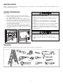 3
3
-
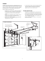 4
4
-
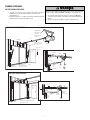 5
5
-
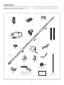 6
6
-
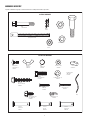 7
7
-
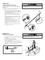 8
8
-
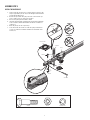 9
9
-
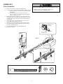 10
10
-
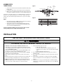 11
11
-
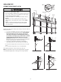 12
12
-
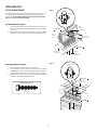 13
13
-
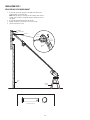 14
14
-
 15
15
-
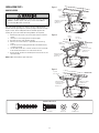 16
16
-
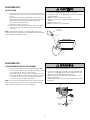 17
17
-
 18
18
-
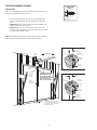 19
19
-
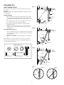 20
20
-
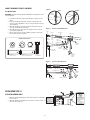 21
21
-
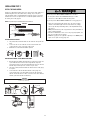 22
22
-
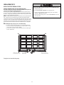 23
23
-
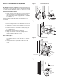 24
24
-
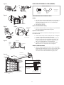 25
25
-
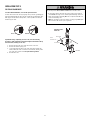 26
26
-
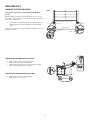 27
27
-
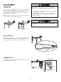 28
28
-
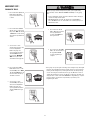 29
29
-
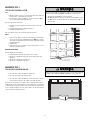 30
30
-
 31
31
-
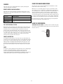 32
32
-
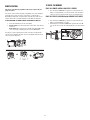 33
33
-
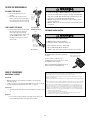 34
34
-
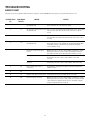 35
35
-
 36
36
-
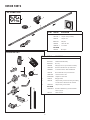 37
37
-
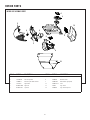 38
38
-
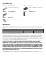 39
39
-
 40
40
-
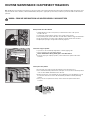 41
41
-
 42
42
-
 43
43
-
 44
44
-
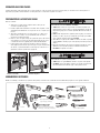 45
45
-
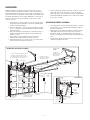 46
46
-
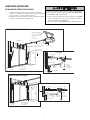 47
47
-
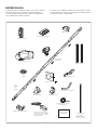 48
48
-
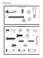 49
49
-
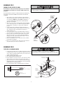 50
50
-
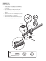 51
51
-
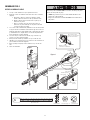 52
52
-
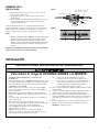 53
53
-
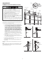 54
54
-
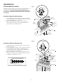 55
55
-
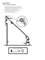 56
56
-
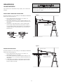 57
57
-
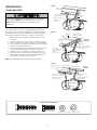 58
58
-
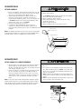 59
59
-
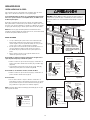 60
60
-
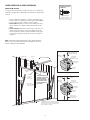 61
61
-
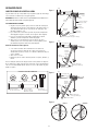 62
62
-
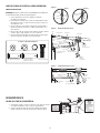 63
63
-
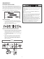 64
64
-
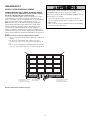 65
65
-
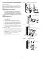 66
66
-
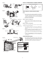 67
67
-
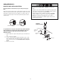 68
68
-
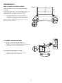 69
69
-
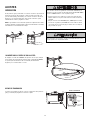 70
70
-
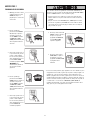 71
71
-
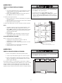 72
72
-
 73
73
-
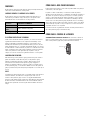 74
74
-
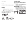 75
75
-
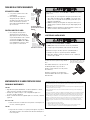 76
76
-
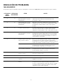 77
77
-
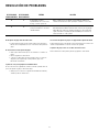 78
78
-
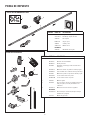 79
79
-
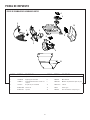 80
80
-
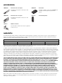 81
81
-
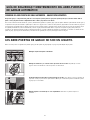 82
82
-
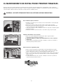 83
83
-
 84
84


Crafstman CMXEDCG471 El manual del propietario
- Categoría
- Abridor de puerta de garage
- Tipo
- El manual del propietario
- Este manual también es adecuado para
en otros idiomas
- English: Crafstman CMXEDCG471 Owner's manual
Artículos relacionados
-
Craftsman CMXEOCG781 El manual del propietario
-
Craftsman CMXEOCG981 El manual del propietario
-
Craftsman CMXEOCG571 El manual del propietario
-
Craftsman CMXEOCG771 El manual del propietario
-
Craftsman CMXEOCG471 El manual del propietario
-
Craftsman CMXZDCG478 El manual del propietario
-
-
Craftsman CMXZDCG453 El manual del propietario
Otros documentos
-
-
-
-
-
Craftsman 139.53962SRT1 El manual del propietario
-
-
-
-
Sears 139.53930D El manual del propietario
-