
SNA-RGW
GB ENGLISH
Subject to change without prior notice
The manual is intended only for qualified, professional and skilled technicians, authorised to act in
accordance with the safety standards provided for the electrical installations.
This person must have appropriate training and wear suitable Personal Protective Equipment.
WARNING!
It is strictly forbidden for anyone who does not have the above-mentioned requires to
install or use the coil.
The coil complies with the European Union directives in force, as well as with the technical
standards implementing these requirements, as certified by the CE mark on the coil and
on this Manual.
It is forbidden to use the coil for purposes other than intended ones, specified in this manual. The
Manufacturer denies liability for any damage to people or property caused by incorrect use of this product.
The information herein contained shall not be disclosed to third parties. Any duplication of this manual,
either partial or total, not authorised in writing by the Manufacturer, violates the terms of copyright and is
punishable by law. Any brand in this publication belong to the legitimate registered owners.
DESCRIPTION
SNA-RGW coil is available in different sizes and can be supplied according to customer’s specifications.
SNA-RGW coil is provided with a shield against the influence of external magnetic fields, therefore it grants
a stable measurement from low currents to hundreds of kA. The Rogowski coils must be connected to an
electronic integrator for phase compensation and frequency equalization.
NOTE
At the opening of the box, check that the Rogowski coil has not been damaged during transport.
If the Rogowski coil appears to be damaged, contact the technical after-sales service.
SAFETY INSTRUCTIONS
The Rogowski coil must be installed in an environment which are according to the max operation conditions of the coil itself.
WARNING!
The connection and installation of the Rogowski coil must be carried out only by qualified
technicians aware of the risks involved to the presence of voltage and current.
Before carrying out an operation, check if:
1. bare conductor wires are not powered, 2. there are no neighbour bare conductors not powered
NOTE
The Rogowski coil complies with the EN61010-1, EN61010-031, EN61010-2-031,
EN61010-2-032 standards and following amendments. The installation must be carried
out in accordance with the standards in force, the instructions of this user manual and the
coil insulation value in order to avoid any danger for people.
SNA-RGW is a sensor for accurate measurement so it must be handled with care. Before use, read the
following instructions carefully.
Do not use the product if damaged.•
Always wear protective clothing and gloves when required.•
Avoid to strongly twist and to blow the product: the measurement accuracy may be impaired.•
Do not paint the product.•
Do not put metallic labels or other objects on the product: the insulation may be impaired.•
It is forbidden any use of the product different from the manufacturer specifications.•
MAINTENANCE
Refer to the following instructions carefully for the product maintenance.
Keep the product clean and free of surface contamination.•
Clean the product with a soft cloth damp with a water and neutral soap. Avoid to use corrosive •
chemical products, solvents or aggressive detergents.
Make sure the product is dry before further use.•
Do not use or leave the product in particularly dirty or dusty environments.•
MOUNTING
WARNING!
Before installing the coil round a conductor not insulated, check that it is not powered
otherwise switch the circuit OFF.
WARNING!
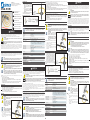
Check if the coil is properly
installed: a bad locking can affect
measurement accuracy and the coil
will become sensitive from adjacent
conductors or other sources of
electromagnetic fields.
NOTE
Coil must not fit tightly round the
conductor, therefore its internal diameter
must exceed that of the conductor.
To carry out the installation, proceed as follow:
Fit the coil round the conductor, bringing the 1.
coil ends together.
Lock the coil by turning the ring as indicated in picture.2.
To open the coil, turn the ring in reverse and 3.
pull out the coil ends.
CONNECTIONS
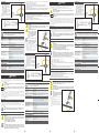
ADVICE
In case of external device with inverting 1.
input, connect the WHITE cable to the
signal input and the BLUE cable to the
common.
In case of external device WITHOUT 2.
inverting input, connect the WHITE cable
to the common and the BLUE cable to the
signal input.
The shield is isolated from the two conductors
and it can withstand maximum 40 V.
TECHNICAL FEATURES
NOTE
For any doubt on the installation procedure or on product application, please contact our
technical services or our local distributor.
COIL
Coil length from 250 to 3000 mm
Coil diameter 8.3 ±0.2 mm
Fastening bayonet holder
Weight from 150 to 500 g
Material thermoplastic polyurethane UL94-V0
ELECTRICAL CHARACTERISTICS
Output level (RMS) 100 mV / kA @50Hz (standard)
For different values, please refer to the product label.
When the coil is purchased combined with an instrument, the output
level is adjusted according to the combined instrument.
Coil resistance from 70 to 900 Ω
Positioning error better than ±1% of reading (with 15 mm diameter cable)
Frequency range approx 40 Hz to 20 kHz
Working voltage 1000 VRMS CAT III
600 VRMS CAT IV
pollution degree 2
Test voltage 7400 Vrms / 1 min
CONNECTION CABLE
Type 2 x 0,15 mm shielded, double insulated, 2xAWG22
Length on request
ENVIRONMENTAL CONDITIONS
Operating temperature from -30°C to +80°C
Storage temperature from -40°C to +80°C
Protection degree IP67
STANDARDS COMPLIANCE
Safety EN61010-1, EN61010-031, EN61010-2-031, EN61010-2-032
1MxMSNARGW08
GB Flexible Rogowski coil
USER MANUAL
D Flexible Rogowskispule
BEDIENUNGSANLEITUNG
I Bobina flessibile Rogowski
MANUALE D’USO
F Sonde flexible de Rogowski
NOTICE D'UTILISATION
ES Bobina flexible Rogowski
MANUAL DEL USUARIO
D DEUTSCH
Änderungen vorbehalten
Dieses Handbuch ist nur für Fachtechniker mit einer elektrotechnischen Ausbildung bestimmt. Die
ortsüblichen Vorschriften, Richtlinien, Bestimmungen und Sicherheitsstandard sind einzuhalten. Dieser
Techniker muss entsprechend geschult werden und geeignete Schutzausrüstung tragen.
WARNHINWEIS!
Es ist jeder Person untersagt, die die oben genannten Anforderungen nicht erfüllt, die Spule
zu installieren oder zu verwenden.
Die Spule wurde gemäß den in der Europäischen Gemeinschaft geltenden Richtlinien und
den technischen Normen hergestellt, und an deren Anforderungen angeglichen. Dies wird
vom CE-Zeichen an der Spule und in dieser Veröffentlichung nachgewiesen.
Es ist absolut verboten, die Spule für anderweitige Anwendungen als für die es hergestellt wurde und die aus
diesem Handbuch erschließbar sind zu verwenden.
Die in diesem Handbuch enthaltenen Informationen dürfen nicht Dritten bekannt gemacht werden. Jede
nicht schriftlich von der Herstellerfirma genehmigte, vollständige oder teilweise Vervielfältigung durch
Fotokopieren, Herstellen einer Abschrift oder mit anderen Systemen, einschließlich des elektronischen
Scannens, verletzt die Copyright-Bedingungen und wird rechtlich verfolgt.
Die in der Veröffentlichung eventuell genannten Warenzeichen gehören den rechtmäßigen Inhabern, von
denen sie eingetragen wurden.
BESCHREIBUNG
Die SNA-RGW Spulen sind in verschiedenen Größen verfügbar und können in kundenspezifischen Eigenschaften
geliefert werden. SNA-RGW ist durch einen Schirm gegen den Einfluss von magnetischen Feldern ausgestattet
und kann somit zur Messung von mA bis zu hunderten kA verwendet werden. Zur Strommessung wird ein
elektrischer Verstärker zum Phasenausgleich und zum Frequenzabgleich benötigt.
ANMERKUNG
Beim Öffnen der Schachtel überprüfen Sie bitte, dass die Spule keine sichtbaren
Transportschäden aufweist. Sollte die Spule beschädigt sein, setzen Sie sich bitte mit dem
technischen Kundendienst in Verbindung.
VORSICHTSMASSNAHMEN
Die Rogowskispule muss in einer Umgebung installiert werden, die den maximalen Betriebsbedingungen
der Spule entsprechen.
WARNHINWEIS!
Der Anschluss und die Installation der Rogowski-Spule darf nur durch qualifiziertes
elektrotechnisches Fachpersonal erfolgen.
Vor der Installation müssen folgende Sicherheitsregeln eingehalten werden:
1. Spannungsfreiheit von offenen Kabeln oder Adern feststellen
2. Benachbarte, unter Spannung stehende Teile abdecken oder abschranken
ANMERKUNG
DDie Rogowski-Spule entspricht den EN61010-1, EN61010-031, EN61010-2-031 EN61010-2 bis
032 Normen. Die Installation muss mit den geltenden Normen übereinstimmen. Um jede Gefahr
für Menschen zu vermeiden, müssen die Hinweise dieser Bedienungsanleitung befolgt werden.
Die Rogowskispule ist ein Wandler zur präzisen Strommessung und muss mit Vorsicht behandelt werden.
Lesen Sie bitte die folgenden Anweisungen sorgfältig durch.
Verwenden Sie das Produkt nicht, wenn es beschädigt ist.•
Schutzkleidung und Schutzhandschuhe sind, wenn erforderlich, immer zu tragen.•
Vermeiden Sie starke Verdrehungen und Verschmutzungen der Spule, die Messgenauigkeit könnte •
beeinträchtigt werden.
Das Produkt darf nicht zweckentfremdet werden.•
Legen Sie keine metallischen Gegenstände auf das Produkt, die Isolierung könnte beeinträchtigt werden.•
Die Verwendung des Produkts abweichend der Herstellerspezifikation ist untersagt.•
WARTUNG
Beachten Sie die folgenden Hinweise für die Produktwartung.
Halten Sie das Produkt sauber und frei von Verunreinigungen.•
Reinigen Sie das Produkt mit einem weichen feuchten Tuch mit Wasser oder einem neutralen •
Reinigungsmittel. Vermeiden Sie ätzende chemische Produkte, Lösungsmittel und aggressive
Reinigungsmittel.
Stellen Sie sicher, dass das Produkt vor der weiteren Verwendung trocken ist.•
Benutzen Sie das Produkt nicht in schmutzigen oder staubigen Bereichen.•
BEFESTIGUNG
WARNHINWEIS!
Vor der Installation der Spule, überprüfen Sie, dass der Stromleiter nicht eingeschaltet ist.
WARNHINWEIS!
Prüfen Sie, ob die Spule korrekt installiert wurde. Ein nicht konformer Einbau kann die
Messgenauigkeit beeinträchtigen. Auch benachbarte Leiter oder andere Verbraucher die ein
elektromagnetisches Feld erzeugen, können die Messung beeinflussen.
ANMERKUNG
Die Messung wird nicht negativ
beeinflusst, wenn die Spule nicht
direkt am Leiter anliegt. Es ist
ausschließlich darauf zu achten, dass
der Außendurchmesser der Spule
größer als der Innendurchmesser des
Leiters ist.
Zur Durchführung der Installation, gehen Sie wie folgt
vor:
Legen Sie die Spule um den Stromleiter und 1.
verbinden diese am Ende.
Verschließen Sie die Spule durch Drehen des 2.
Rings (siehe Abbildung).
Um die Spule zu öffnen, drehen Sie den Ring in 3.
umgekehrter Richtung und ziehen Sie an den
beiden Enden.
ANSCHLUSS
HINWEIS
Bei Verwendung eines externen Gerätes 1.
MIT invertierten Eingang, verbinden Sie
das weiße Kabel mit dem Signaleingang
und das blaue Kabel mit dem Gleichtakt.
Bei Verwendung eines externen Gerätes 2.
OHNE invertierten Eingang, verbinden Sie
das weiße Kabel an den Gleichtakt und das
blaue Kabel mit dem Signaleingang.
Der Schutzleiter ist durch beide Leiter isoliert
und kann mit maximal 40 V beschalten
werden.
TECHNISCHE DATEN
ANMERKUNG
Bei Fragen zur Installation oder Produktanwendung, kontaktieren Sie bitte unseren
technischen Kundendienst.
SPULE
Spulenlänge von 250 bis 3000 mm
Spulendurchmesser 8.3 ±0.2 mm
Befestigung Bajonettfassung
Gewicht von 150 bis 500 g
Material Thermoplastik-Polyurethan UL94-V0
ELEKTRISCHE EIGENSCHAFTEN
Ausgangsspannung (RMS) 100 mV / kA @50Hz (Standard)
Je nach Konfiguration können die verschiedenen Werte variieren. Bitte
entnehmen Sie die exakten Angaben dem Produktschild.
Wenn die Rogowskispule in Kombination mit einem Messgerät gekauft
wurde, wird die Ausgangsspannung dementsprechend angepasst.
Spulenwiderstand von 70 bis 900 Ω
Positionierfehler besser als ±1% Ablesung (mit 15 mm Kabeldurchmesser)
Frequenzbereich ca. 40 Hz bis 20 kHz
Betriebsspannung 1000 VRMS CAT III
600 VRMS CAT IV
Verschmutzungsgrad 2
Prüfspannung 7400 Vrms / 1 Min
VERBINDUNGSKABEL
Typ 2 x 0,15 mm geschirmt, doppelt isoliert, 2xAWG22
Länge auf Anfrage
UMWELTBEDINGUNGEN
Betriebstemperatur von -30°C bis +80°C
Lagerungstemperatur von -40°C bis +80°C
Schutzgrad IP67
REFERENZNORMEN
Sicherheit EN61010-1, EN61010-031, EN61010-2-031, EN61010-2-032
I ITALIANO
Soggetto a modifiche senza preavviso
Questo manuale è destinato esclusivamente ad un utente specializzato. Con tale termine si intende
una figura professionale provvista di una qualifica tecnica specifica, che autorizzi ad operare secondo
gli standard di sicurezza previsti per le installazioni elettriche. Tale figura deve inoltre possedere un
addestramento agli interventi basilari di pronto soccorso, ed essere munita di adeguati Dispositivi di
Protezione Individuale.
AVVERTIMENTO!
E' fatto divieto assoluto di installare ed utilizzare la bobina a chiunque non sia in possesso
delle caratteristiche sopra elencate.
La bobina è realizzata conformemente alle direttive vigenti nella Unione Europea ed
alle norme tecniche che ne recepiscono i requisiti, così come attestato dal marchio CE
presente sulla bobina e nella presente pubblicazione.
E' assolutamente proibito utilizzare la bobina per usi differenti da quelli per cui è stata costruita, desumibili
dal contenuto del presente manuale. Il produttore declina ogni responsabilità per danni a persone o cose
causati dall'uso non corretto di questo prodotto. Le informazioni contenute in questo manuale non sono
divulgabili a terzi. Qualunque duplicazione parziale o totale del manuale, non autorizzata per iscritto dalla
ditta costruttrice, viola le condizioni di copyright ed è giuridicamente perseguibile. I marchi eventualmente
citati nella pubblicazione appartengono ai legittimi proprietari che ne hanno effettuato la registrazione.
DESCRIZIONE
Il sensore SNA-RGW é disponibile in varie lunghezze e può essere fornito secondo le specifiche del cliente.
Il sensore SNA-RGW è provvisto di schermo contro l’influenza di disturbi esterni, pertanto assicura una
misura stabile da basse correnti fino a centinaia di kA. Il sensore Rogowski deve essere abbinato ad un
integratore elettronico per la correzione di fase e per l’equalizzazione in frequenza.
NOTA
All’atto dell’apertura della scatola, verificare che la bobina Rogowski non presenti danni
visibili dovuti al trasporto. Se la bobina Rogowski appare danneggiata, contattare il
servizio di assistenza tecnica.
PRECAUZIONI PER L'USO
La bobina Rogowski deve essere installata in un ambiente che rispetti le caratteristiche massime di lavoro
della bobina stessa.
AVVERTIMENTO!
Il collegamento e l'installazione della bobina Rogowski devono essere effettuati solo da
personale specializzato e a conoscenza dei rischi che la presenza di tensione e di corrente
possono comportare. Prima di effettuare qualsiasi collegamento, accertarsi che:
1. i fili conduttori non protetti non siano sotto tensione
2. non ci siano conduttori non protetti sotto tensione nelle vicinanze
NOTA
La bobina Rogowski è conforme alle normative EN61010-1, EN61010-031, EN61010-2-
031, EN61010-2-032 e successivi aggiornamenti. Al fine di evitare danni alle persone,
effettuare l'installazione secondo le normative vigenti, le indicazioni del presente
manuale e tenendo conto in particolare del valore d'isolamento specificato per la bobina.
SNA-RGW è un sensore di misura di precisione pertanto deve essere trattato con cura.
Prima dell'uso, leggere attentamente le seguenti precauzioni.
Verificare sempre che il prodotto non sia danneggiato.•
Indossare indumenti e guanti di protezione quando previsto.•
Evitare urti e torsioni forzate al prodotto: potrebbe comprometterne la precisione di misura.•
Non dipingere il prodotto.•
Non applicare targhette metalliche o qualsiasi altro oggetto sul prodotto, potrebbero •
comprometterne l'isolamento.
Qualunque uso improprio del prodotto o diverso da quanto specificato dal produttore è vivamente •
sconsigliato.
MANUTENZIONE
Per la corretta cura del prodotto, leggere attentamente le seguenti indicazioni.
Tenere la sonda sempre pulita e libera da contaminazioni superficiali.•
Pulire il prodotto con un panno morbido inumidito con acqua e sapone neutro. Evitare di usare prodotti •
chimici corrosivi, solventi o detergenti aggressivi.
Prima dell'uso, assicurarsi che il prodotto sia completamente asciutto.•
Non utilizzare o lasciare il prodotto in ambienti particolarmente sporchi.•
MONTAGGIO
AVVERTIMENTO!
Prima di installare la bobina attorno ad un conduttore non isolato, verificare che non sia
sotto tensione. In caso contrario, togliere alimentazione al circuito.
AVVERTIMENTO!
Verificare che la bobina sia stata installata correttamente: una chiusura errata della
bobina potrebbe influire sulla precisione della misura e questa potrebbe essere
influenzata dalla presenza di
conduttori esterni o altre sorgenti
di campi elettromagnetici.
NOTA
La bobina non deve avvolgere
il conduttore stringendolo: il
diametro interno della bobina
deve sempre eccedere quello del
conduttore.
Per effettuare l'installazione, procedere come
segue:
Avvolgere la bobina intorno al conduttore, 1.
congiungendo le due estremità della
bobina.
Fissare la chiusura ruotando la ghiera come 2.
indicato in figura.
Per aprire la bobina, ruotare la ghiera 3.
all'inverso e allontanare le due estremità
della bobina.
SIMEX Sp. z o.o.
ul. Wielopole 11 • 80-556 Gdańsk Poland
Tel. (+48 58) 76-20-777 • Fax (+48 58) 76-20-770
www.simex.pl • [email protected]

COLLEGAMENTI
SUGGERIMENTO
Nel caso di dispositivo esterno con 1.
ingresso invertente, collegare il cavo
BIANCO all'ingresso di segnale e il
cavo BLU al comune.
Nel caso di dispositivo esterno con 2.
ingresso NON invertente, collegare il
cavo BIANCO al comune e il cavo BLU
all'ingresso di segnale.
Lo schermo è isolato dai due conduttori
e può sopportare una tensione massima
di 40 V.
CARATTERISTICHE TECNICHE
NOTA
Per qualsiasi dubbio sulla procedura d'installazione o sull'uso del prodotto, contattare
l'assistenza tecnica oppure il distributore locale.
SENSORE
Lunghezza bobina da 250 a 3000 mm
Diametro della corda 8.3 ±0.2 mm
Chiusura a baionetta
Peso da 150 a 500 g
Materiale poliuretano termoplastico UL94-V0
CARATTERISTICHE ELETTRICHE
Livello di uscita (RMS) 100 mV / kA @50Hz (standard)
Per valori diversi, fare sempre riferimento all'etichetta del prodotto.
Se la bobina è stata acquistata in abbinamento con uno strumento, il
livello di uscita è regolato in base allo strumento abbinato.
Resistenza del sensore da 70 a 900 Ω
Errore di posizione migliore di ±1% della lettura (con un diametro conduttore di 15 mm)
Frequenza ca. 40 Hz a 20 kHz
Tensione di isolamento 1000 VRMS CAT III
600 VRMS CAT IV
grado di inquinamento 2
Tensione di prova 7400 Vrms / 1 min
CAVO DI COLLEGAMENTO
Tipo 2 x 0,15 mm schermato, doppio isolamento, 2xAWG22
Lunghezza a richiesta
CONDIZIONI AMBIENTALI
Temperatura di funzionamento da -30°C a +80°C
Temperatura di stoccaggio da -40°C a +80°C
Grado di protezione IP67
NORME DI CONFORMITA'
Sicurezza EN61010-1, EN61010-031, EN61010-2-031, EN61010-2-032
F FRANÇAIS
Susceptible de modification sans préavis
Ce manuel est destiné aux professionnels, ou techniciens qualifiés, autorisés à agir en conformité avec les
normes de sécurité relatives aux installations électriques. Ces personnes doivent porter les équipements
de protection individuels nécessaires.
ATTENTION!
Il est strictement interdit pour quiconque n’ayant pas les agréments requis d’installer ou
d’utiliser ces sondes.
Les sondes répondent aux directives Européennes en cours, ainsi qu’aux normes
techniques correspondantes, comme certifié par le logo CE présent sur les sondes et ce
manuel.
Il est interdit d’utiliser les sondes pour des applications différentes de celles pour lesquelles elles sont
conçues, non spécifiées dans ce manuel. Le fabricant rejette toute responsabilité sur l’endommagement
causé par une personne ou par des conditions relatives à une mauvaise utilisation.
Les informations ici énoncées ne doivent pas être transcrites par une tierce personne. Toute duplication
de ce manuel, en partie ou totale, non autorisée par écrit par le fabricant, violerait les termes du copyright
et serait condamnable par la loi.
DESCRIPTION
SNA-RGW est disponible en tailles différentes et peut être personnalisée.
Cette sonde est livrée avec une protection contre l’influence des champs magnétiques externes, garantissant
la stabilité des mesures même pour des courants inférieurs à quelques centaines de kA.
La sonde doit être connectée à un intégrateur électronique pour la compensation de phase et la mise à
niveau de fréquence.
NOTE
A l’ouverture du sachet, vérifiez que la sonde n’a pas été endommagée pendant le
transport. Si la sonde apparaisse endommagée, contactez le service après vente.
CONSIGNES DE SECURITE
La sonde doit être installée dans un environnement respectant les conditions d’utilisation de la sonde.
ATTENTION!
La connexion et l’installation de la sonde doivent être réalisés uniquement par un
technicien qualifié avertit des risques possibles dus à la présence de tension et de
courant. Avant toute opération, vérifiez que:
1. Les câbles conducteurs ne soient pas alimentés
2. Il n’y a aucun conducteur voisin nu non alimenté
NOTE
La sonde réponde aux normes EN61010-1, EN61010-031, EN61010-2-031, EN61010-2-
032 et respecte les amendements. L’installation doit être réalisées en accord avec les
normes en vigueur, avec les instructions de ce manuel et avec les valeurs d’isolement
adaptés à la sonde, afin d’éviter tout danger pour les utilisateurs.
La SNA-RGW est une sonde dédiée aux mesures précises de courant, et doit être manipulée avec précautions.
Avant toute utilisation, lire les instructions suivantes.
Ne pas utiliser le produit s’il est endommagé.•
Toujours porter une tenue adaptée de sécurité et des gants lorsque cela est nécessaire.•
Eviter de tordre et cogner fortement la sonde: la précision de mesure pourrait être altérée.•
Ne pas peindre la sonde.•
Ne pas ajouter d’étiquette métallique ou d’autres objets sur le produit: son isolement pourrait être altéré.•
Toute utilisation du produit de manière non conforme aux instructions du fabriquant est prohibée.•
MAINTENANCE
Se référer aux instructions suivantes.
Garder la sonde propre et hors de portée de surfaces de contamination.•
Nettoyer la sonde avec un chiffon doux légèrement imbibé d’eau. Eviter d’utiliser des produits corrosifs, •
des solvants ou des détergents.
S’assurer que la sonde soit sèche avant toute utilisation.•
Ne pas utiliser la sonde dans des environnements sales ou poussiéreux.•
INSTALLATION
ATTENTION!
Avant de positionner la sonde autour d’un conducteur non isolé, vérifiez que celui-ci n’est
pas alimenté, sinon couper l’alimentation avant de procéder à la mise en place.
ATTENTION!
Vérifiez que la sonde soit correctement
installée: un mauvais verrouillage
peut affecter la précision des mesures
et la sonde deviendrait sensible aux
champs électromagnétiques des
sources environnantes.
NOTE
La sonde ne doit pas être serrée
autour du conducteur, par conséquent
son diamètre interne doit être
supérieur à celui du conducteur.
Pour l’installation, procédez comme suit:
Passez la sonde autour du conducteur, 1.
rassemblez les extrémités de la sonde.
Verrouillez la sonde en tournant l’anneau 2.
comme illustré ci-dessous.
Pour ouvrir la sonde, tournez l’anneau dans le 3.
sens contraire et séparez les extrémités.
CONNEXIONS
AVIS
En case d'appareil externe avec entrée 1.
inversante, connecter le câble BLANC
à l'entrée du signal et le câble BLEU à
l'entrèe du commun.
En case d'appareil externe SANS entrée 2.
inversante, connecter le câble BLANC à
l'entrée du commun et le câble BLEU à
l'entrèe du signal.
Le blindage est isolé par les deux conducteurs
et il peut résister à une tension maximum
de 40 V.
SPECIFICATIONS
NOTE
En cas de doute sur la procédure d’installation ou d’utilisation du produit, contactez nos
services techniques ou notre distributeur local.
SONDE
Longueur de sonde de 250 à 3000 mm
Diamètre de sonde 8.3 ±0.2 mm
Verrouillage par baïonnette
Poids de 150 à 500 g
Matière thermoplastique en polyurethane UL94-V0
SPECIFICATIONS ELECTRIQUES
Niveau de sortie (RMS) 100 mV / kA @50Hz (standard)
Pour des valeurs différentes, se référer à l’étiquette du produit.
Quand la sonde est achetée en combinaison avec un appareil, le
niveau de sortie est réglé selon l'appareil combiné.
Résistance de sonde de 70 à 900 Ω
Erreur de positionnement meilleur que ±1% de la lecture (avec diamètre de câble 15 mm)
Gamme de fréquence environ 40 Hz à 20 kHz
Niveau de sécurité 1000 VRMS CAT III
600 VRMS CAT IV
Degré de pollution 2
Tension de test 7400 Vrms / 1 min
CABLE DE CONNEXION
Type 2 x 0,15 mm blindé, double isolation, 2xAWG22
Longueur Sur demande
CONDITIONS ENVIRONNEMENTALES
Température d’utilisation de -30°C à +80°C
Température de stockage de -40°C à +80°C
Indice de protection IP67
CONFORMITE
Normes EN61010-1, EN61010-031, EN61010-2-031, EN61010-2-032
ES ESPAÑOL
Sujeto a cambios sin previo aviso
El manual está destinado exclusivamente a técnicos cualificados, profesionales y expertos autorizados para
actuar de acuerdo con las normas de seguridad previstas en las instalaciones eléctricas.
Esta persona debe tener una formación adecuada y llevar equipo adecuado de protección personal.
¡ADVERTENCIA!
Está estrictamente prohibido para cualquier persona que no se ha mencionado anteriormente
a instalar o utilizar la bobina.
La bobina cumple con las directivas de la Unión Europea en vigor, así como con las normas
técnicas de ejecución de estos requisitos, según lo certificado por la marca CE en la bobina y
en este Manual.
Está prohibido el uso de la bobina para fines distintos a los previstos que se especifican en este manual. El
fabricante niega toda responsabilidad por daños a personas o propiedades causados por el uso incorrecto de
este producto. La información aquí contenida no será revelada a terceros. La reproducción de este manual,
ya sea total o parcial, no autorizada expresamente por escrito por el fabricante, viola los términos de los
derechos de autor y está penado por la ley. Cualquier marca en esta publicación pertenecen a los legítimos
propietarios registrados.
DESCRIPCIÓN
Bobina SNA-RGW está disponible en diferentes tamaños y se puede suministrar de acuerdo con el diseño del
cliente. La bobina SNA-RGW está provista de un escudo contra la influencia de campos magnéticos externos, por
lo tanto, concede una medida estable desde bajas corrientes hasta cientos de kA. Las bobinas de Rogowski deben
estar conectados a un integrador electrónico para la compensación de fase y respuesta de frecuencia.
NOTA
En la apertura de la caja, compruebe que la bobina de Rogowski no haya sufrido daños
durante el transporte. Si la bobina Rogowski parece estar dañada, póngase en contacto con
el servicio técnico de post-venta.
INSTRUCCIONES DE SEGURIDAD
La bobina Rogowski se debe instalar en un entorno que esté de acuerdo con las condiciones de operación
máximas de la bobina.
¡ADVERTENCIA!
La conexión y la instalación de la bobina Rogowski se debe realizar únicamente por técnicos
cualificados que sean conscientes de los riesgos que implica la presencia de tensión y de
corriente. Antes de llevar a cabo una operación, compruebe si:
1. Los hilos conductores desnudos no están alimentados
2. No exista en las proximidades ningún conductor desnudo alimentado
NOTA
La bobina Rogowski cumple con la norma EN61010-1, EN61010-031, EN61010-2-031,
EN61010-2-032 y sus sucesivas modificaciones. La instalación debe ser llevada a cabo de
conformidad con las normas vigentes, las instrucciones de este manual del usuario y el valor
de aislamiento de la bobina, con el fin de evitar cualquier peligro para las personas.
La bobina SNA-RGW es un sensor para una medición muy precisa, por lo que debe ser manejado con cuidado.
Antes de usar, lea atentamente las siguientes instrucciones.
No utilice el producto si está dañado.•
Siempre use ropa protectora y guantes cuando sea necesario.•
Evite torcer fuertemente y golpear o punzar el producto; la precisión de la medición puede verse •
afectada.
No pinte el producto.•
No coloque etiquetas metálicas u otros objetos en el producto: el aislamiento puede verse afectado.•
Está prohibido cualquier uso del producto diferente de las especificaciones del fabricante.•
MANTENIMIENTO
Consulte las siguientes instrucciones para el mantenimiento del producto.
Mantenga el producto limpio y libre de suciedad en la superficie.•
Limpie el producto con un paño suave humedecido con agua y jabón neutro. Evite el uso de productos •
químicos corrosivos, disolventes o detergentes agresivos.
Asegúrese de que el producto esté seco antes de su uso.•
No utilice ni deje el producto en entornos particularmente sucios o polvorientos.•
MONTAJE
¡ADVERTENCIA!
Antes de instalar la bobina alrededor de un conductor no aislado, compruebe que no está
alimentado, de lo contrario desconectar el circuito.
¡ADVERTENCIA!
Verifique si la bobina está correctamente instalada: un mal bloqueo puede afectar la precisión
de la medición y la bobina se vuelve sensible a los conductores adyacentes u otras fuentes de
campos electromagnéticos.
NOTA
La bobina no debe quedar apretada
en torno al conductor, por lo que su
diámetro interno debe ser superior a
la del conductor.
Para llevar a cabo la instalación, proceda de la
siguiente manera:
Colocar la bobina alrededor del conductor, 1.
uniendo los extremos.
Cerrar y asegurar la bobina girando el anillo de 2.
bloqueo como se indica en la figura.
Para abrir la bobina, gire el anillo de bloqueo 3.
en sentido inverso y saque los extremos de la
bobina.
CONEXIONES
CONSEJOS
.En caso del acondicionador de señal 1.
externo con entrada invertida, conecte
el cable BLANCO a la entrada de señal
y el cable AZUL al común.
En caso del acondicionador de señal 2.
externo SIN entrada invertida, conecte
el cable BLANCO al común y el cable
AZUL a la entrada de señal.
El apantallado está aislado de los dos
conductores y puede soportar un máximo
40 V.
CARACTERISTICAS TÉCNICAS
NOTA
Para cualquier duda sobre el procedimiento de instalación o en la aplicación del producto,
por favor póngase en contacto con nuestro servicio técnico o con su distribuidor local.
BOBINA
Longitud de la bobina de 250 a 3000 mm
Diámetro de la bobina 8.3 ±0.2 mm
Cierre bayoneta
Peso de 150 a 500 g
Material poliuretano termoplástico UL94-V0
CARACTERISTICAS ELECTRICAS
Nivel de salida (RMS) 100 mV / kA @50Hz (Normalizado)
Para diferentes valores, por favor consulte la etiqueta del producto.
Cuando la bobina se compra en combinación con un instrumento, el
nivel de salida se ajusta de acuerdo con el instrumento combinado.
Resistencia de la bobina de 70 a 900 Ω
Error de posicionamiento mejor del ±1% de la lectura (con un cable de 15 mm de diámetro)
Rango de frecuencias 40 Hz a 20 kHz aproximadamente
Tensión de aislamiento 1000 VRMS CAT III
600 VRMS CAT IV
grado de polución 2
Tensión de prueba 7400 Vrms / 1 min
CABLE DE CONEXIÓN
Tipo 2 x 0,15 mm apantallado, doble aislamiento, 2xAWG22
Largo bajo demanda
CONDICIONES AMBIENTALES
Temperatura de funcionamiento da -30°C a +80°C
Temperatura de almacenamiento da -40°C a +80°C
Grado de protección IP67
CUMPLIMIENTO DE NORMAS
Seguridad EN61010-1, EN61010-031, EN61010-2-031, EN61010-2-032
-
 1
1
-
 2
2


En otros idiomas
- français: Simex SNA-L70 Le manuel du propriétaire
- italiano: Simex SNA-L70 Manuale del proprietario
- Deutsch: Simex SNA-L70 Bedienungsanleitung
- português: Simex SNA-L70 Manual do proprietário
Otros documentos
-
CARLO GAVAZZI ROG4X1002M2503X El manual del propietario
-
-
Sonel MPI-540-PV Manual de usuario
-
Amprobe AU92 Automotive Multimeter Manual de usuario
-
Greenlee 52086133 REV1 Manual de usuario
-
-
-
Multimetrix CM604 AC CLAMP METER Manual de usuario
-
RS PRO 161-1631 Manual de usuario
-