Bitspower BPTA-O11D-MINI_A3.0-BK Guía de instalación
- Tipo
- Guía de instalación

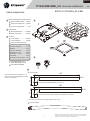
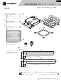
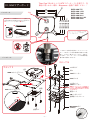
Parts List
— 1 —
English
TITAN ONE MINI_3.0 Installation Guide
BPTA-O11D-MINI_A3.0-BK
B-1 B-2
A-1
A-2
A-3
248
55
A
B
C
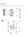
Hard Tube
C-1
Drain Tube
C-2
V3
:16
284
55
:16
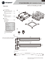
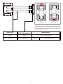
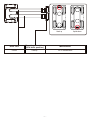
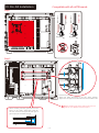
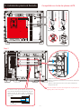
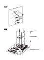
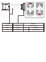
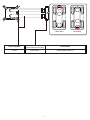
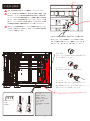
The allowable variance in tube length is ± 2mm
For standard MATX mother board (24x 24cm).
For the ITX motherboard or not standard size MATX motherboard.
............1 pc
Intel Mounting Bracket
CPU Water Block
A
..........1 pc
BPTA-CPUMS-V2-SKA
A-1
A-2
...............1 set
Backplane Assembly
A-3
Fittings
B
.................2 pcs
BPTA-DOTFH1622
B-1
....................2 pcs
BPTA-15ATFH16
B-2
Accessory
C
...............................4 pcs
Hard Tube
C-1
..............................1 pc
Drain Tube
C-2
CPU set
C-3
BP-CPUPDB-AMD5MS
C-5
Thumb screw
SPRING
Thumb nut
1mm Spacer
M3x32mm Screw
SC6-32M3
Nylon cup washer
.................4 pcs
.................4 pcs
.................4 pcs
...........4 pcs
..................8 pcs
.....................4 pcs
.........................4 pcs
BPTA-MKCPUMS-1700 or
BPTA-MKCPUMS-1700-V2
C-4
Please refer to the tables on pages 5 and 16
for Hard Tubes+Motherboard compatibility.
Bitspower reserves the right to change the product design and interpretations.
These are subject to change without notice. Product colors and accessories
are based on the actual product.

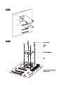
EX.
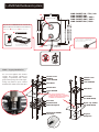
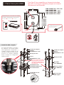
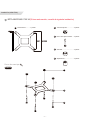
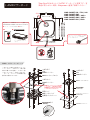
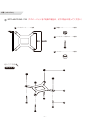
I. AMD Motherboard system
— 2 —
M3x32mm SCREW
(for Intel)
1mm SPACER
Back Pad
3M Paste Pad
Metal Backplane
Thumb screw
SPRING
CPU Block
1mm SPACER
Thumb screw
CPU Block
SC6-32M3
(for AMD AM4)
Nylon cup washer
(for AMD AM4)
Original
backplane
SPRING
1mm SPACER
Thumb Nut
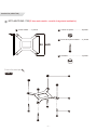
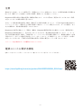
96
90
48
54
AMD SOCKET AM4
AMD SOCKET AM3 / AM3+
AMD SOCKET AM2 / AM2+
AMD SOCKET FM1 / FM2+
AMD SOCKET 939 / 754 / 940
AMD SOCKET AM4
AMD SOCKET AM3 / AM3+
AMD SOCKET AM2 / AM2+
AMD SOCKET FM1 / FM2+
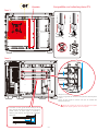
AM4 + Legacy Installation
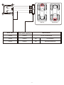
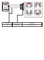
DRGB LED
IN
OUT
DRGB PIN on Motherboard or other equipment.
Motherboard
Fan and DRGB RF Remote
Controller Hub (Not included)
BPTA-RFCHUB
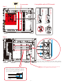
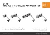
Do not over-tighten the thumb
screws. The springs should be
slightly compressed, with visible
gaps in the spring coils. Over-tight-
ening may result in poor contact
between the water block and CPU.
Use an appropriate amount
of Thermal Compound, - high-end
Bitspower cooling products are now
available at microcenter.com.
The CPU water block has a DRGB cable, which
can be connected to the DRGB extension
cable of the radiator fans.
Bitspower Fan and DRGB RF Remote Controller Hub
(Not included) are now available at microcenter.com

— 3 —
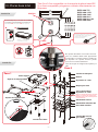
1
4
2
3
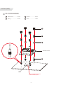
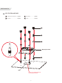
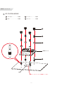
CPU Water block
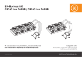
Installation(AM5)
BP-CPUPDB-AMD5MS
C-5
1
42
3
Thumb screw.................4 PCS
Stud..........................4 PCS
Spring .............................4 PCS
Washer.....................4 PCS
Use an appropriate amount
of Thermal Compound
CPU

— 4 —
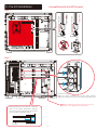
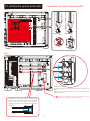
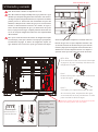
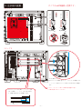
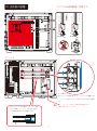
Hard tube BPTA-15ATFH16
II. Pre-Fill Installation
Step 1
Step 2
When installing the hard pipe from the CPU
block to the water distribution reservoir,
You can move the hard pipe left and right to
get the proper installation length.
Compatible with all mATX boards.
Loosen the screws.
Adjust the slider according to the CPU block position.
Adjust the hard pipe to the same level as the CPU Block inlet.
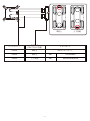
Hard tube BPTA-15ATFH16
Before installing the water cooling parts for the
graphics card, please remove this part.
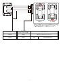
PUMP HEADER
FULL SPEED
AIO_PUMP
PUMP HEADER
PWM CONTROL
CPU_FAN

5
— —
Upside downHead up
Hard Tube Motherboard
Mounting orientation
(CPU block position)
55x248 Head up All mATX motherboards
55x248 Head up PRO B650M-A WIFIMSI
In the event that the CPU Block is oriented higher than the
maximum default height of the Distribution Blocks' sliding CPU
Terminal, it is possible to rotate the face of the Terminal 180°
into its Upside Down position. This should allow the terminal to
match the height of the CPU Block.

— 6 —
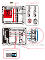
Step 1
Step 2
When installing the hard pipe from the CPU
block to the water distribution reservoir,
You can move the hard pipe left and right to
get the proper installation length.
It’s removable
Before installing the water cooling parts for the
graphics card, please remove this part.
Loosen the screws.
Adjust the slider according to the CPU block position.
Adjust the hard pipe to the same level as the CPU Block inlet.
Hard tube BPTA-15ATFH16
Compatible with all ITX boards.
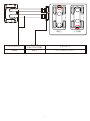
PUMP HEADER
FULL SPEED
AIO_PUMP
PUMP HEADER
PWM CONTROL
CPU_FAN

7
— —
Upside downHead up
Hard Tube Motherboard
Mounting orientation
(CPU block position)
55x284 Head up All ITX motherboards

— 8 —
Thumb screw
SPRING
CPU Block
1mm SPACER
M3x32mm SCREW
(for Intel)
1mm SPACER
Back Pad
3M Paste Pad
Metal Backplane
Thumb Nut
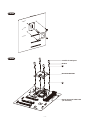
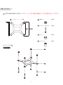
EX.
80
75
72
INTEL LGA 775
INTEL LGA 115X
INTEL LGA 1366
INTEL LGA 2011
INTEL LGA 2011-V3
INTEL LGA 2066
INTEL LGA 775
INTEL LGA 115X
INTEL LGA 1366
INTEL LGA 2011
INTEL LGA 2011-V3
INTEL LGA 2066
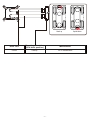
IN
OUT
A-2
DRGB PIN on Motherboard or other equipment.
Motherboard
Fan and DRGB RF Remote
Controller Hub (Not included)
BPTA-RFCHUB
Installation
The CPU water block has a DRGB cable, which
can be connected to the DRGB extension
cable of the radiator fans.
Fin
Base screw
Base
Top
Intel Mounting Bracket
AMD Mounting Bracket
Installation
Do not over-tighten the thumb screws. The
springs should be slightly compressed, with
visible gaps in the spring coils. Over-tighten-
ing may result in poor contact between the
water block and CPU.
Bitspower Fan and DRGB RF Remote Controller Hub
(Not included) are now available at microcenter.com
Use an appropriate amount
of Thermal Compound, - high-end
Bitspower cooling products are now
available at microcenter.com.
Step 1
Step 2
III. Intel Motherboards Titan One 3.0 is compatible with most ATX motherboards.
If not compatible, please contact Bitspower directly.

— 9 —
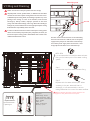
4
1 2
3
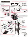
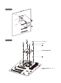
Assembly steps
step 1
1
2
3
Installation(LGA 1700)
C-4
BPTA-MKCPUMS-1700(If you got this version, please refer to the following installation)
Backplate ............................1 PC Adjusting Nut..........................8 PCS
Backplane Bolt .......................4 PCS
Washer...................................4 PCS

—
10
—
step 3
step 2
4
2

—
11
—
1
Assembly steps
step 1
1
2
3
Installation(LGA 1700)
BPTA-MKCPUMS-1700-V2(If you got this version, please refer to the following installation)
C-4
4
2
3
5
Backplate ............................1 PC Adjusting Nut..........................4 PCS
Backplane Bolt .......................4 PCS
Washer...................................4 PCS
Standoffs................................4 PCS

12
— —
step 3
step 2
4
5

PUMP HEADER
FULL SPEED
AIO_PUMP
PUMP HEADER
PWM CONTROL
CPU_FAN
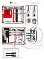
Step 1
Step 2
When installing the hard pipe from the CPU
block to the water distribution reservoir,
You can move the hard pipe left and right to
get the proper installation length.
Compatible with all mATX boards.
Loosen the screws.
Adjust the slider according to the CPU block position.
Adjust the hard pipe to the same level as the CPU Block inlet.
IV. Pre-Fill Installation
13
— —
Before installing the water cooling parts for the
graphics card, please remove this part.

14
— —
Upside downHead up
Hard Tube Motherboard
Mounting orientation
(CPU block position)
55x248 Head up All mATX motherboards
55x248 Head up PRO B660M-AMSI
55x248 Head up MAG B660M MORTARMSI

PUMP HEADER
FULL SPEED
AIO_PUMP
PUMP HEADER
PWM CONTROL
CPU_FAN
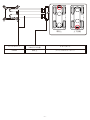
Step 1
Step 2
When installing the hard pipe from the CPU
block to the water distribution reservoir,
You can move the hard pipe left and right to
get the proper installation length.
Compatible with all ITX boards.
It’s removable
Loosen the screws.
Adjust the slider according to the CPU block position.
Adjust the hard pipe to the same level as the CPU Block inlet.
Before installing the water cooling parts for the
graphics card, please remove this part.
15
— —

16
— —
Upside downHead up
Hard Tube Motherboard
Mounting orientation
(CPU block position)
55x284 Head up All ITX motherboards

BPTA-EFW
It is recommended to install the water-exhaust
fitting at the lowest point of the water cooling
system.
Step 1
Unscrew the top of the water-exhaust fitting.
AIO_PUMP
PUMP HEADER
PWM CONTROL
CPU_FAN
PUMP HEADER
FULL SPEED
AIO_PUMP
CPU_FAN
A Negative electrode -
B positive electrode +
C Speed signal
A B C D
Step 2
Replace with the water-exhaust part. When
screwing in the part, water will start to
discharge, it is recommended to connect
tubing beforehand to control the water outflow.
Pump Spec.
Rated voltage:12V DC
Power consumption:8.4W
Maximum flow:460±15%L/h
Noise:≦24dBA
PWM:Yes
MTBF:≦15,000 hours
Warranty:2 years
Water filling hole
90% full
Before installing the water cooling parts for the
graphics card, please remove this part.
17
— —
V. Filling and Draining
Notice : Do not turn on the pump if the reservoir is empty.
Only Bitspower Coolant, purified water, or distilled water should be
used for the consumer's liquid-cooling fluid. If the consumer choos-
es different liquid-cooling fluids, the resulting impurities may cause
peeling of the coating on some of the hardware, water channel
block-age by built-up residue, improper operation of the water
pump, water tank tube breakage, and O-ring deformation leading to
leakage. Any issues related to the use of inappropriate liquid-cooling
fluid will be the responsibility of the consumer.
In order to make the internal circulation of the liquid-cooling system
cleaner and avoid the pump stuck by the precipitate, we advise you
torinse the liquid-cooling system with distilled water several times
until theexcluded water is clean. Pour the coolant into the reservoir via the water filling
hole. Once the reservoir is 90% full, turn on the power
supply for the pump to run and let the air exit the loop.
Turn off the power supply when the reservoir is near
empty. Repeat until all the air has exited the loop.

Notice
Before filling in the water, please make sure all the components are installed correctly. To prevent any leakage
which may damage the PC components, please perform a 24-hour leaking test with only the pump connected
to the power supply.
Bitspower reserves the right to change the product design and interpretations. These are subject to change
without notice. Product colors and accessories are based on the actual product.
When using leak tester on water cooling loop, in order to avoid product damage due to excessive pressure, the
input pressure should not exceed 0.5kg/cm2 (Bar). If the product is damaged due to excessive pressure, it will be
borne by the customer. Forbidden to use the leak teser when there is water in the loop or the pump is runing.
Bitspower recommends to use of distilled or pure water or Bitspower Pellucid Coolant as the water-cooling
liquid. Also, the consumer can add Bitspower Dye to Pellucid Coolant for the color requirement. But please do
not add any biocide by yourself. If the consumer chooses different water-cooling liquids, the resulting impurities
may cause peeling off the coating on some of the hardware, water channels blockage by built-up residue,
improper operation of the water pump, water tank tube breakage, and O-rings deformation or loss sealing lead-
ing to leakage. Any issues related to the use of inappropriate water-cooling liquid will be the responsibility of the
consumer.
Do not turn on the pump if the reservoir is empty.
About PSU
Please go to the website or scan the QR CODE to download the manual.
https://www.fsplifestyle.com/en/product/DAGGERPRO850W_GEN5.html
18
— —

— 1 —
TITAN ONE MINI_3.0 Guía de instalación
BPTA-O11D-MINI_A3.0-BK
Spanish
B-1 B-2
A-1
A-2
A-3
248
55
A
B
C
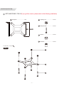
Tubos rígidos
C-1
Tubo de drenaje
C-2
V3
:16
284
55
:16
La variación permitida en la longitud del tubo es de ±2 mm
Para placa base MATX estándar (24 × 24 cm).
Para placa base ITX o placa base MATX de tamaño no estándar.
Consulte las tablas de las páginas 5 y 16
para conocer la compatibilidad de los tubos
rígidos y la placa base.
Lista de componentes
...1 piezas
Soporte de montaje Intel
Bloque de refrigeración líquida para CPU
A
......1 piezas
BPTA-CPUMS-V2-SKA
A-1
A-2
...........1 set
Conjunto de placa base
A-3
Equipamiento
B
............2 piezas
BPTA-DOTFH1622
B-1
.................2 piezas
BPTA-15ATFH16
B-2
Accesorio
C
......................4 piezas
Tubos rígidos
C-1
.................1 piezas
Tubo de drenaje
C-2
Juego de bloques para CPU
C-3
BP-CPUPDB-AMD5MS
C-5
Tornillo de mariposa
MUELLE
Tuerca de mariposa
Separador de 1 mm
Tornillo M3 × 32 mm
SC6-32M3
Arandela de copa de nailon
..............4 pcs
..4 pcs
.............................4 pcs
..............4 pcs
..............8 pcs
..............4 pcs
...............................4 pcs
BPTA-MKCPUMS-1700 or
BPTA-MKCPUMS-1700-V2
C-4
Bitspower se reserva el derecho de modificar el diseño y las interpretaciones
del producto. Estos están sujetos a cambios sin previo aviso. Los colores del
producto y los accesorios se basan en el producto real.

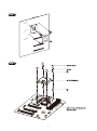
EX.
— 2 —
96
90
48
54
AMD SOCKET AM4
AMD SOCKET AM3 / AM3+
AMD SOCKET AM2 / AM2+
AMD SOCKET FM1 / FM2+
AMD SOCKET 939 / 754 / 940
AMD SOCKET AM4
AMD SOCKET AM3 / AM3+
AMD SOCKET AM2 / AM2+
AMD SOCKET FM1 / FM2+
I. Placas base para AMD
Led DRGB
C
FUERA
PIN DRGB en la placa base u otro equipo.
Placa base
Ventilador y remoto DRGB RF
Controlador (no incluido)
BPTA-RFCHUB
El bloque de refrigeración líquida para CPU tiene
un cable DRGB, que se puede conectar al
cable de extensión DRGB de los
ventiladores del radiador.
El ventilador Bitspower y el controlador remoto DRGB RF
(no incluido) ya están disponibles en microcenter.com
Titan One 3.0 es compatible con la mayoría de placas
base ATX. Si no fuera compatible, póngase en contacto
directamente con Bitspower.
Instalación AM4 + Legado
No apriete demasiado los tornillos
de mariposa. Los muelles deben
estar ligeramente comprimidos y
contener espacios visibles en las
espirales. Un apriete excesivo puede
provocar un contacto deficiente
entre el bloque de refrigeración
líquida y la CPU.
Tornillo M3×32mm
(para Intel)
SEPARADOR de 1mm
Almohadilla trasera
Almohadilla adhesiva 3M
Placa base metálica
Tornillo de mariposa
MUELLE
Bloque para CPU
SEPARADOR de 1mm
Tornillo de mariposa
Bloque para CPU
SC6-32M3
(para AMD AM4)
Nylon cup washer
(para AMD AM4)
Placa base para
AMD original
MUELLE
SEPARADOR de 1mm
Tuerca
Utilice una cantidad adecuada de
compuesto térmico. Los productos
de refrigeración de Bitspower de
gama alta ya están disponibles en
microcenter.com.

— 3 —
1
4
2
3
Bloque para CPU
Utilice una cantidad adecuada
de compuesto térmico
CPU
AM5 Instalación
BP-CPUPDB-AMD5MS
C-5
1Tornillo de mariposa....4
piezas
4Taco........................4
piezas
2Resorte...........................4
piezas
3Arandela.................4
piezas

— 4 —
Hard tube BPTA-15ATFH16
Step 1
Step 2
Al instalar el tubo rígido desde el bloque de la
CPU hasta el depósito de distribución de agua,
puede mover el tubo rígido a izquierda y
derecha para obtener la longitud de instalación
adecuada.
Compatible con todas las placas mATX.
Afloje los tornillos.
Ajuste el regulador de acuerdo con la posición del bloque
de la CPU.
Ajuste el tubo rígido al mismo nivel que la entrada del
bloque de la CPU.
Tubos rígidos BPTA-15ATFH16
II. Instalación previa al llenado
Antes de instalar las piezas de refrigeración líquida para la
tarjeta gráfica, retire esta pieza.
VELOCIDAD TOTAL
AIO_PUMP
CABEZAL DE LA BOMBA
CABEZAL DE LA BOMBA
CONTROL
PWM
CPU_FAN

5
— —
Hacia abajoHacia arriba
Tubos rígidos Placa bases
Orientación de montaje
(posición del bloque de la CPU)
55x248 Hacia arriba La mayoría de las placas base ATX
55x248 Hacia arriba PRO B650M-A WIFIMSI
En caso de que el bloque de la CPU esté orientado a una altura
superior a la altura máxima predeterminada del terminal
deslizante de la CPU de los bloques de distribución, es posible
girar la parte frontal del terminal 180° a su posición invertida.
Esto debería permitir que el terminal coincida con la altura del
bloque de la CPU.

— 6 —
Paso 1
Paso 2
When installing the hard pipe from the CPU
block to the water distribution reservoir,
You can move the hard pipe left and right to
get the proper installation length.
Extraíble
Before installing the water cooling parts for the
graphics card, please remove this part.
Loosen the screws.
Adjust the slider according to the CPU block position.
Adjust the hard pipe to the same level as the CPU Block inlet.
Hard tube BPTA-15ATFH16
Compatible con todas las placas ITX.
VELOCIDAD TOTAL
AIO_PUMP
CABEZAL DE LA BOMBA
CABEZAL DE LA BOMBA
CONTROL
PWM
CPU_FAN

7
— —
Hacia abajoHacia arriba
Tubos rígidos Placa bases
Orientación de montaje
(posición del bloque de la CPU)
55x284 Hacia arriba Todas las placas base ITX

— 8 —
EX.
80
75
72
INTEL LGA 775
INTEL LGA 115X
INTEL LGA 1366
INTEL LGA 2011
INTEL LGA 2011-V3
INTEL LGA 2066
INTEL LGA 775
INTEL LGA 115X
INTEL LGA 1366
INTEL LGA 2011
INTEL LGA 2011-V3
INTEL LGA 2066
DENTRO
FUERA
A-2
Instalación
Instalación
Paso 2
III. Placas base Intel Titan One 3.0 es compatible con la mayoría de placas base ATX.
Si no fuera compatible, póngase en contacto directamente con
Bitspower.
PIN DRGB en la placa base u other equipment.
Placa base
Ventilador y remoto DRGB RF
Controlador (no incluido)
BPTA-RFCHUB
El bloque de refrigeración líquida para CPU tiene
un cable DRGB, que se puede conectar al
cable de extensión DRGB de los
ventiladores del radiador.
El ventilador Bitspower y el controlador remoto DRGB RF
(no incluido) ya están disponibles en microcenter.com
No apriete demasiado los tornillos de mari-
posa. Los muelles deben estar ligeramente
comprimidos y contener espacios visibles en
las espirales. Un apriete excesivo puede
provocar un contacto deficiente
entre el bloque de refrigeración líquida y la
CPU.
Tornillo de mariposa
MUELLE
Bloque para CPU
Separador de 1 mm
Tornillo M3×32mm
(para Intel)
Separador de 1mm
Almohadilla trasera
Almohadilla adhesiva 3M
Placa base metálica
Tuerca de mariposa
Aleta
Tornillo de la base
Base
Parte superior
Soporte de montaje Intel
Soporte de montaje AMD
Utilice una cantidad adecuada de compuesto
térmico. Los productos de refrigeración de
Bitspower de gama alta ya están disponibles
en microcenter.com.
Paso 1

— 9 —
4
1 2
3
Pasos de montaje
Paso 1
1
2
3
Instalación (LGA 1700)
BPTA-MKCPUMS-1700(Si tiene esta versión, consulte la siguiente instalación)
C-4
Placa trasera
Perno de la placa trasera
Tuerca de ajuste
.......1 piezas ...................8 piezas
.......4 piezas
Arandela ...............................4 piezas

—
10
—
Paso 3
Paso 2
4
2
Tornillo de mariposa
MUELLE
BPTA-CPUMS-SKI
Placas base Intel LGA 1700
(no incluidas)

—
11
—
1
Pasos de montaje
Paso 1
1
2
3
Instalación (LGA 1700)
BPTA-MKCPUMS-1700-V2(Si tiene esta versión, consulte la siguiente instalación)
C-4
Placa trasera
4
2
3
5
Perno de la placa trasera
Tuerca de ajuste
Arandela
Separadores
.............1 piezas ...................4 piezas
......4 piezas
...............................4 piezas
.........................4 piezas

—
12
—
Paso 3
Paso 2
4
5
Tornillo de mariposa
MUELLE
BPTA-CPUMS-SKI
Placas base Intel LGA 1700
(no incluidas)

Paso 1
Paso 2
Al instalar el tubo rígido desde el bloque de la
CPU hasta el depósito de distribución de agua,
puede mover el tubo rígido a izquierda y
derecha para obtener la longitud de instalación
adecuada.
Compatible con todas las placas mATX.
Afloje los tornillos.
Ajuste el regulador de acuerdo con la posición del bloque de
la CPU.
Ajuste el tubo rígido al mismo nivel que la entrada del
bloque de la CPU.
IV. Instalación previa al llenado
13
— —
Antes de instalar las piezas de refrigeración líquida
para la tarjeta gráfica, retire esta pieza.
VELOCIDAD TOTAL
AIO_PUMP
CABEZAL DE LA BOMBA
CABEZAL DE LA BOMBA
CONTROL
PWM
CPU_FAN

14
— —
Hacia abajoHacia arriba
Tubos rígidos Placa base
Orientación de montaje
(posición del bloque de la CPU)
55x248 Hacia arriba Todas las placas base mATX
55x248 Hacia arriba PRO B660M-AMSI
55x248 Hacia arriba MAG B660M MORTARMSI

Paso 1
Paso 2
Extraíble
15
— —
PUMP HEADER
FULL SPEED
AIO_PUMP
PUMP HEADER
PWM CONTROL
CPU_FAN
Al instalar el tubo rígido desde el bloque de la
CPU hasta el depósito de distribución de agua,
puede mover el tubo rígido a izquierda y
derecha para obtener la longitud de instalación
adecuada.
Compatible con todas las placas ITX.
Afloje los tornillos.
Ajuste el regulador de acuerdo con la posición del bloque de
la CPU.
Ajuste el tubo rígido al mismo nivel que la entrada del
bloque de la CPU.
Antes de instalar las piezas de refrigeración líquida
para la tarjeta gráfica, retire esta pieza.

16
— —
Hacia abajoHacia arriba
Tubos rígidos Placa base
Orientación de montaje
(posición del bloque de la CPU)
55x284 Hacia arriba Todas las placas base ITX

PUMP HEADER
FULL SPEED
PUMP HEADER
PWM CONTROL
BPTA-EFW
Se recomienda instalar el accesorio de escape
de agua en el punto más bajo del sistema de
refrigeración líquida.
Paso 1
Desatornille la parte superior del accesorio de
escape de agua.
Paso 2
Sustitúyalo por la pieza de escape de agua.
Al enroscar la pieza, empezará a salir agua,
se recomienda conectar previamente un tubo
para controlar la salida de agua.
Orificio de llenado de agua
90 % lleno
AIO_PUMP
CABEZAL DE LA BOMBA
CONTROL PWM
CPU_FAN
CABEZAL DE LA BOMBA
VELOCIDAD TOTAL
AIO_PUMP
CPU_FAN
A Electrodo negativo -
B Electrodo positivo +
C Señal de velocidad
A B C D
Espec. de la bomba
Tensión nominal:12V DC
Consumo:8.4W
Flujo máximo:460±15%L/h
Ruido:≦24dBA
PWM:Yes
MTBF:≦15,000 hours
Garantía:2 years
Antes de instalar las piezas de refrigeración líquida
para la tarjeta gráfica, retire esta pieza.
17
— —
Vierta el refrigerante en el depósito a través del orificio de
llenado de agua. Una vez que el depósito esté lleno al 90
%, encienda la fuente de alimentación para que la bomba
funcione y deje que el aire salga del circuito. Desconecte la
alimentación cuando el depósito esté casi vacío. Repita la
operación hasta que todo el aire haya salido del circuito.
V. Llenado y vaciado
Nota: No encienda la bomba si el depósito está vacío.
Solo debe utilizarse refrigerante Bitspower, agua purificada o agua
destilada para el líquido refrigerante del consumidor. Si el consumi-
dor elige un líquido refrigerante diferente, las impurezas resultantes
pueden provocar la descamación del revestimiento de parte del
hardware, el bloqueo de los canales de agua por la acumulación de
residuos, el funcionamiento incorrecto de la bomba de agua, la
rotura del tubo del depósito de agua y la deformación de la junta
tórica, lo que provocaría fugas. Cualquier problema relacionado con
el uso de un líquido refrigerante inadecuado será responsabilidad
delconsumidor.
Para que la circulación interna del sistema de refrigeración líquida
sea más limpia y evitar que la bomba se atasque por el precipitado,
recomendamos enjuagar el sistema de refrigeración líquida con
agua destilada varias veces hasta que el agua excluida esté limpia.

—
18
—
Nota
Antes de llenar con líquido, asegúrese de que todos los componentes están instalados correctamente. Para
evitar cualquier fuga que pueda dañar los componentes del PC, realice una prueba de fugas de 24horas solo
con la bomba conectada a la fuente de alimentación.
Bitspower se reserva el derecho de modificar el diseño y las interpretaciones del producto. Estos están sujetos a
cambios sin previo aviso. Los colores del producto y los accesorios se basan en el producto real.
Cuando utilice el detector de fugas en un circuito de refrigeración líquida, para evitar daños en el producto
debidos a una presión excesiva, la presión de entrada no debe superar los 0,5kg/cm2 (bar). Si el producto se
daña debido a una presión excesiva, será culpa del cliente. NO utilice el detector de fugas cuando haya agua en
el circuito o la bomba esté en funcionamiento.
Bitspower exige el uso de agua destilada, agua purificada o refrigerante pelúcido Bitspower como líquido refrig-
erante. El consumidor también puede añadir tinte Bitspower al refrigerante pelúcido según su preferencia de
color. No añada ningún biocida. Si el consumidor elige un líquido refrigerante diferente, las impurezas resul-
tantes pueden provocar la descamación del revestimiento de parte del hardware, el bloqueo de los canales de
agua por la acumulación de residuos, el funcionamiento incorrecto de la bomba de agua, la rotura del tubo del
depósito de agua y la deformación o pérdida de sellado de las juntas tóricas, lo que provocaría fugas. Cualquier
problema relacionado con el uso de un líquido refrigerante inadecuado será responsabilidad del consumidor.
No encienda la bomba si el depósito está vacío.
Información sobre la fuente de alimentación
Escanee el CÓDIGO QR o visite el siguiente sitio web para descargar el manual.
https://www.fsplifestyle.com/en/product/DAGGERPRO850W_GEN5.html

— 1 —
TITAN ONE MINI_3.0
BPTA-O11D-MINI_A3.0-BK
B-1 B-2
A-1
A-2
A-3
248
55
A
B
C
C-1
C-2
V3
:16
284
55
:16
± 2mm
標準mATXマザーボード(24 x 24cm)用。
ITXマザーボードまたは標準のmATXマザーボード以外のサイズ用。
部品一覧
日本語
Intel
CPU
A
BPTA-CPUMS-V2-SKA
A-1
A-2
A-3
金具
B
BPTA-DOTFH1622
B-1
BPTA-15ATFH16
B-2
C
C-1
C-2
CPU
C-3
BP-CPUPDB-AMD5MS
C-5
1mm
M3x32mm
SC6-32M3
.............................4 個数
....4 個数
.............................4 個数
.......................4 個数
....................8 個数
...........................4 個数
.......................................4 個数
BPTA-MKCPUMS-1700 or
BPTA-MKCPUMS-1700-V2
C-4
....................1 個数
........................4 個数
.....................2 個数
.................2 個数
...1
..........1 個数
...........1 個数
5 16
Bitspower

EX.
— 2 —
96
90
48
54
AMD SOCKET AM4
AMD SOCKET AM3 / AM3+
AMD SOCKET AM2 / AM2+
AMD SOCKET FM1 / FM2+
AMD SOCKET 939 / 754 / 940
AMD SOCKET AM4
AMD SOCKET AM3 / AM3+
AMD SOCKET AM2 / AM2+
AMD SOCKET FM1 / FM2+
DRGB LED
入力
出力
AM4 + レガシーインストール
つまみネジを締付け過ぎないように
してください。ばねはコイル間で隙
間が目視できる程度に、わずかに押
し込んでください。締付けすぎると
、ウォーターブロックとCPU間の接
触不良の原因となります。
I. AMDマザーボード Titan One 3.0はほとんどのATXマザーボードと互換です。互
換性が得られない場合、Bitspowerへ直接ご相談ください。
マザーボードやその他の機器でのDRGBピン。
マザーボード
ファンとDRGB RFリモコンハブ
(別売り)
BPTA-RFCHUB
CPUウォーターブロックはDRGBケーブルを備え
ており、ラジエーターファンのDRGB延長
ケーブルへ接続できます。
BitspowerファンとDRGB RFリモコンハブ(別売り)は、
microcenter.comでお求めいただけるようになりました。
M3x32mm
Intel
1mm
3M
CPU
1mm
適量のサーマルコンパウンドを使用
してください。上位のBitspower冷
却製品はmicrocenter.comでお求め
いただけるようになりました。
CPU
SC6-32M3
1mm

— 3 —
1
4
2
3
CPU
AM5 インストール
BP-CPUPDB-AMD5MS
C-5
1つまみネジ.....................4 個数
4スタッド...................4 個数
2ばね.................................4 個数
3ワッシャー...............4 個数
適量のサーマルコンパウンドを使用してください。
CPU

— 4 —
Hard tube BPTA-15ATFH16
ステップ 1
ステップ 2
CPUブロックから貯水槽へハードパイプを取
り付ける場合、ハードパイプを左右に動かし
て、設置に適切な長さに調整できます。
すべてのmATX基板と互換です。
ネジを緩めます。
CPUブロックの位置に基づいて、スライダーを調整します
。
ハードパイプをCPUブロックの給水口と同じ高さに調整し
ます。
ハードチューブ BPTA-15ATFH16
グラフィックスカード用に水冷部品を設置する前に、
この部品を取り外してください。
II. 注水前の設置
AIO_PUMP
PWM 制御
CPU_FAN

5
— —
取付方向
(CPUブロック位置)
55x248 ATX
55x248 PRO B650M-A WIFIMSI
CPUブロックが配水ブロックのスライドCPU端子のデフォルト高よ
り高い場合、端子面を180°上下に回転させることができます。これ
で、端子の高さがCPUブロックの高さと等しくなります。

— 6 —
ステップ1
ステップ2
CPUブロックから貯水槽へハードパイプを取
り付ける場合、ハードパイプを左右に動かし
て、設置に適切な長さに調整できます。
グラフィックスカード用に水冷部品を設置する前に、
この部品を取り外してください。
ネジを緩めます。
CPUブロックの位置に基づいて、スライダーを調整します
。
ハードパイプをCPUブロックの給水口と同じ高さに調整し
ます。
ハードチューブ BPTA-15ATFH16
すべてのITX基板と互換です。
AIO_PUMP
PWM 制御
CPU_FAN

7
— —
取付方向
(CPUブロック位置)
55x284 ITX

— 8 —
EX.
80
75
72
INTEL LGA 775
INTEL LGA 115X
INTEL LGA 1366
INTEL LGA 2011
INTEL LGA 2011-V3
INTEL LGA 2066
INTEL LGA 775
INTEL LGA 115X
INTEL LGA 1366
INTEL LGA 2011
INTEL LGA 2011-V3
INTEL LGA 2066
A-2
インストール
インストール
III. Intelマザーボード Titan One 3.0はほとんどのATXマザーボードと互換です。互
換性が得られない場合、Bitspowerへ直接ご相談ください。
マザーボードやその他の機器でのDRGBピン。
マザーボード
ファンとDRGB RFリモコンハブ
(別売り)
BPTA-RFCHUB
CPUウォーターブロックはDRGBケーブルを備え
ており、ラジエーターファンのDRGB延長
ケーブルへ接続できます。
BitspowerファンとDRGB RFリモコンハブ(別売り)は、
microcenter.comでお求めいただけるようになりました。
つまみネジを締付け過ぎないようにしてくだ
さい。ばねはコイル間で隙間が目視できる程
度に、わずかに押し込んでください。締付け
すぎると、ウォーターブロックとCPU間の接
触不良の原因となります。
2
Fin
上面
Intel
AMD
1
CPU
1mm
M3x32mm
Intel
1mm
3M
適量のサーマルコンパウンドを使用して
ください。上位のBitspower冷却製品は
microcenter.comでお求めいただけるよ
うになりました。
入力
出力

— 9 —
4
1 2
3
1
2
3
設置(LGA 1700)
ステップ 1
BPTA-MKCPUMS-1700
C-4
組み立て手順

—
10
—
4
2
BPTA-CPUMS-SKI
ステップ 3
ステップ 2
ステップ 3
LGA 1700 Intel

—
11
—
1
1
2
3
4
2
3
5
設置(LGA 1700)
BPTA-MKCPUMS-1700-V2
C-4
ステップ 1
組み立て手順

—
12
—
4
5
BPTA-CPUMS-SKI
ステップ 2
ステップ 3
LGA 1700 Intel

すべてのmATX基板と互換です。
13
— —
IV. 注水前の設置
Hard tube BPTA-15ATFH16
ステップ 1
ステップ 2
CPUブロックから貯水槽へハードパイプを取
り付ける場合、ハードパイプを左右に動かし
て、設置に適切な長さに調整できます。
ネジを緩めます。
CPUブロックの位置に基づいて、スライダーを調整します
。
ハードパイプをCPUブロックの給水口と同じ高さに調整し
ます。
ハードチューブ BPTA-15ATFH16
グラフィックスカード用に水冷部品を設置する前に、
この部品を取り外してください。
AIO_PUMP
PWM 制御
CPU_FAN

14
— —
取付方向
(CPUブロック位置)
55x248 mATX
55x248 PRO B660M-AMSI
55x248 MAG B660M MORTARMSI

15
— —
すべてのITX基板と互換です。
ステップ1
ステップ2
CPUブロックから貯水槽へハードパイプを取
り付ける場合、ハードパイプを左右に動かし
て、設置に適切な長さに調整できます。
グラフィックスカード用に水冷部品を設置する前に、
この部品を取り外してください。
ネジを緩めます。
CPUブロックの位置に基づいて、スライダーを調整します
。
ハードパイプをCPUブロックの給水口と同じ高さに調整し
ます。
ハードチューブ BPTA-15ATFH16
AIO_PUMP
PWM 制御
CPU_FAN

16
— —
55x284 ITX

PUMP HEADER
FULL SPEED
PUMP HEADER
PWM CONTROL
BPTA-EFW
水冷システムの最低点で排水金具を取り付け
ることを推奨いたします。
ステップ 1
排水金具の上部を緩めて取り外します。
ステップ 2
排水部品を交換します。部品を取り付けると、
排水が開始されます。水が流れ出す前にチューブ
を取り付けることを推奨いたします。.
注水口
90%満杯
AIO_PUMP
PWM 制御
CPU_FAN
AIO_PUMP
CPU_FAN
A 負極 -
B 正極 +
C 速度信号
A B C D
ポンプ仕様
定格電圧:12V DC
消費電力:8.4W
最大流量:460±15%L/h
ノイズ:≦24dBA
PWM:あり
平均故障間隔:≦15,000時間
保証:2年
グラフィックスカード用に水冷部品を設置する前に、
この部品を取り外してください。
17
— —
注水口から冷却剤を貯水槽へ注ぎ込みます。貯水槽が90%一
杯になったら、ポンプの電源をオンにして空気を外へ逃がし
ます。貯水槽がほぼ空になったら、電源をオフにします。空
気がすべて外へ逃げるまで、繰り返してください。
V. 注水と排水
注意:貯水槽が空の場合、ポンプの電源をオンにしないでください。
ユーザーが利用できる冷却用液体は、Bitspower冷却剤、濾過水、蒸留
水のみです。ユーザーが別の冷却用液体を使用する場合、不純物が残っ
てハードウェアの一部で被膜が剥離したり、残留物が堆積して水路が塞
がれたり、水ポンプが動作不良を起こしたり、水タンクのチューブが破
損したり、Oリングが変形して水漏れを起こすことがあります。不適切
な冷却用液体を使用する場合の責任はユーザーが負うものとします。
水冷システムの内部循環を良くし、ポンプが沈殿物で詰まらないように
するため、排水がきれいになるまで、水冷システムを蒸留水で数回水洗
いすることを推奨いたします。

—
18
—
注意
液体を注入する前に、すべての部品が正しく設置されていることを確かめてください。PC部品を破損する液漏れを
防ぐため、電源へポンプを接続した状態で24時間、液漏れテストを実施してください。
Bitspowerは製品の設計と製造を変更する権利を保有します。これらは予告なく変更されることがあります。製品
の色とアクセサリは実際の製品に基づきます。
水冷ループで漏れ検出器を使用する場合、過度の圧力で製品が破損しないように、入圧は0.5kg/cm2(Bar)を越えな
いようにしてください。過度の圧力で製品が破損した場合は、ユーザーの責任となります。ポンプの作動中、また
は水の循環中は、漏れ検出器を使用してはなりません。
Bitspowerは冷却用の液体として、蒸留水、濾過水、Bitspower透明冷却剤のみを指定しています。透明冷却剤へ
Bitspowerの染色剤を追加して、好みの色にすることもできます。殺生物剤の追加は避けてください。ユーザーが
別の冷却用液体を使用する場合、不純物が残ってハードウェアの一部で被膜が剥離したり、残留物が堆積して水路
が塞がれたり、水ポンプが動作不良を起こしたり、水タンクのチューブが破損したり、Oリングが変形して水漏れ
を起こすことがあります。不適切な冷却用液体を使用する場合の責任はユーザーが負うものとします。
リザーバーが空の場合はポンプの電源を入れないでください
QRコードをスキャンするか、ウェブサイトへ進んでマニュアルをダウンロードできます。
https://www.fsplifestyle.com/en/product/DAGGERPRO850W_GEN5.html
-
 1
1
-
 2
2
-
 3
3
-
 4
4
-
 5
5
-
 6
6
-
 7
7
-
 8
8
-
 9
9
-
 10
10
-
 11
11
-
 12
12
-
 13
13
-
 14
14
-
 15
15
-
 16
16
-
 17
17
-
 18
18
-
 19
19
-
 20
20
-
 21
21
-
 22
22
-
 23
23
-
 24
24
-
 25
25
-
 26
26
-
 27
27
-
 28
28
-
 29
29
-
 30
30
-
 31
31
-
 32
32
-
 33
33
-
 34
34
-
 35
35
-
 36
36
-
 37
37
-
 38
38
-
 39
39
-
 40
40
-
 41
41
-
 42
42
-
 43
43
-
 44
44
-
 45
45
-
 46
46
-
 47
47
-
 48
48
-
 49
49
-
 50
50
-
 51
51
-
 52
52
-
 53
53
-
 54
54
-
 55
55


Bitspower BPTA-O11D-MINI_A3.0-BK Guía de instalación
- Tipo
- Guía de instalación
en otros idiomas
Artículos relacionados


Otros documentos
-
NZXT Kraken 240 Manual de usuario
-
Corsair HYDRO Series H100i RGB PLATINUM SE Extreme Performance 240mm RGB Liquid CPU Cooler Manual de usuario
-
-
Asus ROG RYUJIN 240 Guía del usuario
-
 ekwb EK-AIO 120 D-RGB Guía de instalación
-
NZXT KRAKEN X Series Guía del usuario
-
-
 ekwb EK-Nucleus AIO CR360 Lux D-RGB Guía de instalación
-
 ekwb EK-Nucleus AIO CR240 Lux D-RGB Guía de instalación
-


