La página se está cargando...

ITEM #2593021/ #2808041/ #2808042
GABLED SOFT-TOP
GAZEBO
MODEL #TPGAZ2307/ #TPGAZ2307A/ #TPGAZ2307B
1
VR20276
Español p. 22
Serial Number ____________________________ Purchase Date _________________________
Questions, problems, missing parts? Before returning to your retailer, call our
customer service department at 1-877-888-8225, 8 a.m. - 8 p.m., EST, Monday - Sunday.
STYLE SELECTIONS and logo design are trademarks
or registered trademarks of LF, LLC.
All Rights Reserved.

P4
P1
P1
P1
P
P1
S
L
R1
P2
P2
P2
P2
2
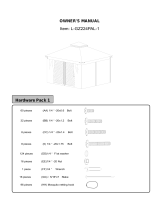
PACKAGE CONTENTS
L
Hook
1
S
Small Canopy
1
S1
Small Netting
1
1
Decorative Ball
P4
DESCRIPTION
1
Connection Tube
Connection Frame
2
PART
P
Center Device
Q
Small Top Frame
P1
Long Small Top Bracing
P3
R
1
Small Canopy Tube
R1
4
Short Small Top Bracing
P2
QUANTITY
2
2
4
DESCRIPTION
PART
QUANTITY
P3
Q
Q
R
R
Q
P3
S1

T
M
W
J1
H1
H1
H1
H1
J
J
J
J
H4
H4
H4
H4
H2
H2
H2
H2
3
PACKAGE CONTENTS
G1
Left Bracing
4
T
Big Canopy
1
4
Long Top Bar
J
PART
DESCRIPTION
4
Roof Tube
Middle Vertical Beam
4
PART
H1
Middle Beam
J1
Connector
QUANTITY
G2
Right Bracing
H2
M
DESCRIPTION
QUANTITY
4
4
4
H3
Middle left Bracing
4
4
Triangle Netting
W
H4
Middle Right Bracing
4
H3
G1
G1
G1
G1
G2
G2
G2
G2
H3
H3
H3

4
PACKAGE CONTENTS
A
Post
4
O1
Base
4
8
Beam Connector
I
PART
DESCRIPTION
4
Decorative Cover
Left Beam
4
PART
B2
Right Support Bar
K
Top Bar Connector
QUANTITY
B1
Left Support Bar
C1
N
DESCRIPTION
QUANTITY
4
4
4
C2
Right Beam
4
4
Base Cover
O2
16
Curtain
Netting Tube Connector
4
E
Netting Tube
U
Mosquito Net
D
Protection Corner
F
V
4
4
4
4′
4
′
1′
1′
3′
3′
2′
2′
4′
4′
1′
1′
3′
3′
2′
2′
A
O2
O2
O2
O2
O1
D
D
D
D
N
N
N
N
I
I
I
I
K
K
K
K
V
U
C1
C1
C1
C1
C2
C2
C2
C2
O1
O1
O1
B1
B1
B1
B1
B2
B2
B2
B2
A
A
A
E
E
E
E
E
E
F
F
F
F
E
E

5
tloB mm 51 × 6M
Qty.
tloB mm 51 × 6M
Qty. 8 + 1 Extra
212 + 6 Extra
AA
tloB mm 30 × 6M
Qty.
8
+ 1 Extra
KK
HARDWARE CONTENTS (shown actual size)
M6 × 70 mm Bolt
Qty. 8 + 1 Extra
BB CC DD
Handle Screw
Qty.8 + 1
Extra
Handle Screw
Qty.
4
+ 1 Extra
M6 × 55 mm Bolt
Qty. 8 + 1 Extra
EE
Flat Washer
Qty. 252 + 10 Extra
FF
Bolt Cover
Qty. 236 + 9 Extra
GG HH II JJ
Nut
Qty.16
+ 2 Extra
Qty.
16
+ 2 Extra
Cap
Plastic Gasket
Qty.
16
+ 2 Extra
Ring
Qty. 80 + 4 Extra
Wrench
Allen Wrench
Qty. 2
(NOT TO SCALE)
(NOT TO SCALE)
NN OOMMLL
Stake
Qty. 16
(NOT TO SCALE)
(NOT TO SCALE)
PP
Qty. 1
(NOT TO SCALE)

A
A
6
SAFETY INFORMATION
PREPARATION
Please read and understand this entire manual before attempting to assemble, operate or install
the product.
WARNING
• Maximum load for the roof hook: 26 lbs.
• WARNING: KEEP ALL FLAME AND HEAT SOURCES AWAY FROM THIS TENT FABRIC.
This tent meets the CPAI-84 flammability requirements. The fabric may burn if left in continuous
contact with any flame source. The application of any foreign substance to the tent fabric may
render the flame-resistant properties ineffective.
CAUTION
Before beginning assembly of product, make sure all parts are present. Compare parts with package
contents list and hardware contents list. If any part is missing or damaged, do not attempt to
assemble the product.
Estimated Assembly Time: 2 hours
Tools Required for Assembly (not included): Safety goggles, Gloves, Hardhat, Stepladder.
SET UP YOUR GAZEBO PROPERLY
• 4 people are recommended for safe assembly.
• Keep all children, pets and other obstructions away from assembly area.
• If any part is missing or damaged, do not attempt to assemble the product.
• In order to avoid damage to the gazebo and its components please use appropriate tools.
• Do not use the structure as support.
• Check all bolts on a regular basis to maintain the solidity of the structure.
• Keep instructions for future use.
• Do not climb on top of the gazebo. Falling off the gazebo can result in serious injury,
possibly even death.
EXAMINE YOUR GAZEBO
• Examine occasionally to ensure there are no loose parts.
If loose parts are found, they should be retightened immediately.
• If high winds, heavy rains or snow occurs, remove roof,
Mosquito Net and Curtain,
and check for damage before continued use.
Safety goggles
Gloves
Stepladder
Hardhat

AA
FF
GG
NN
AA
FF
GG
NN
1
7
ASSEMBLY INSTRUCTIONS
GG
GG
AA
FF
FF
O2
AA
A
A
O2
O1
Wrench
Hardware Used
1. Slide the Base Cover (O2) over the
bottom of the Post (A) and connect
the Base (O1) to the Post (A) with
Bolt (AA) plus Flat Washer (FF).
Add Bolt Cover (GG). Repeat for all
four posts.
2. Insert the Beam Connector (I) into
the Right Beam (C2) and add the
Decorative Cover (K). Then connect
the Left Beam (C1), attach with Bolt
(AA) plus Flat Washer (FF). Add Bolt
Cover (GG). Repeat for all four sides.
NOTE: Pls do not install the screws
under the Decorative Cover (K) in
this step.
Bolt Cover
X24
X24
X24
X1
Flat Washer
X8
X8
X8
X1
M6 x 15 mm Bolt
Wrench
Bolt Cover
Flat Washer
M6 x 15 mm Bolt
Hardware Used
2
C2
C2
K
I
I
I
C2
C1
K
I
I
GG
FF
C1
C2
K
AA
GG
FF
AA
C2
GG
AA
FF
FF
AA
GG
I
C1
K
I
C1
C2
C2
C1
C2
C1
C1
C2

AA
FF
GG
NN
8
ASSEMBLY INSTRUCTIONS
Bolt Cover
Flat Washer
X8
X8
X8
X1
M6 x 15 mm Bolt
3. Connect the Netting Tube Connector
(F) to the beam with Bolt (AA), Flat
Washer (FF) and Bolt Cover (GG).
Hardware Used
Wrench
3
K
K
F
F
C2
C2
C1
C1
AA
GG
FF
C2
C1
K
E
E
F

ASSEMBLY INSTRUCTIONS
AA
FF
GG
NN
9
X32
X32
X32
X1
Wrench
Bolt Cover
Flat Washer
M6 x 15 mm Bolt
Hardware Used
4. Connect the assembled Beam
(C1/C2) to the Post (A), attach with
Bolt (AA), Flat Washer (FF) and Bolt
Cover (GG).
Stand the assembled structure of
posts (A) and beams (C1/C2) up with
two people. Repeat for opposite side
and add two side beams to complete
four sided structure.
4
C2
C2
C2
C1
C1
A
A
GG
FF
AA
C1
C1
C2
A
A
A
A
C1
C2
A
A
A
C2
C2
C2
C2
K
A
A
A
FF
AA
GG
C2
C1
C1

6. Insert one end of the Netting Tube (E)
into the Netting Tube Connector (F), fix
the other end onto the beam with Bolt
(BB), Flat Washer (FF) and Plastic
Gasket (JJ). Repeat for all four sides.
AA
FF
GG
NN
X32
X32
X32
X1
Wrench
Bolt Cover
Flat Washer
M6 x 15 mm Bolt
Hardware Used
ASSEMBLY INSTRUCTIONS
5. Connect the Beam (B1/B2) to the
Post (A) and the Beam (C1/C2)
respectively by Bolts (AA), Flat Washer
(FF) and Bolt Cover (GG).
10
5
6
A
C2
C2
C2
C2
B2
B2
B2
B2
C1
C1
C1
C1
A
A
A
B1
B1
B1
B1
JJ
F
JJ
FF
FF
BB
GG
A
C2
C2
C2
C2
B2
B2
B2
B2
C1
C1
C1
C1
A
A
A
B1
B1
B1
B1
B1
B2
C2
C1
GG
GG
FF
FF
FF
A
AA
AA
AA
AA
F
JJ
JJ
BB
FF
GG
JJ
NN
Bolt Cover
Flat Washer
X8
X8
X8
X16
X1
M6 x 70 mm Bolt
Hardware Used
Wrench
Plastic Gasket

AA
FF
GG
NN
8
X4
X4
X4
X1
Wrench
Bolt Cover
Flat Washer
M6 x 15 mm Bolt
Hardware Used
ASSEMBLY INSTRUCTIONS
8. Connect the Connection Tube (Q)
with the Small Top Frame (R) by
Bolt (AA), Flat Washer (FF) and
Bolt Cover (GG).
11
FF
FF
AA
GG
Q
R
R
AA
FF
GG
NN
X20
X20
X20
X1
Wrench
Bolt Cover
Flat Washer
M6 x 15 mm Bolt
Hardware Used
7.1. Connect the Top Bar Connector
(N) to the post (A) by Bolt (AA), Flat
Washer (FF) and Bolt Cover (GG).
7.2. Put the Protection Corner (D)
over the corner of the Left Beam (C1)
and the Right Beam (C2), and tighten
it by Bolt (AA), Flat Washer (FF) and
Bolt Cover (GG).
7
C2
C2
C2
C2
C1
C1
C1
N
GG
FF
AA
D
C2
C1
GG
FF
AA
C2
C1
N
N
N
N
C1

12
AA
KK
FF
GG
HH
II
NN
9
X8
X4
X16
X12
X4
X4
X2
M6 x 15 mm Bolt
ASSEMBLY INSTRUCTIONS
9.1. Assemble the two Small Top
Frame (R), connect all the Small Top
Connecting Frame (P3) to the Small
Top Frame (R) respectively, then
tighten them by Bolt (AA), Flat Washer
(FF) and Bolt Cover (GG).
9.2. Attach the Connection Frame (P3)
to the Connection Tube(Q) by Bolt
(AA), Flat Washer (FF) and Bolt Cover
(GG).
9.3. Put the Hook (L) onto the Small
Canopy Tube (R1).
9.4. Attach the Small Canopy Tube
(R1) to the Small Top Connecting
Frame (P3) by Bolt (KK) and Nut
(HH), Cap (II) and Bolt Cover (GG).
P3
R
R
R
R1
L
GG
FF
AA
GG
FF
GG
FF
R1
HH
FF
II
KK
KK
GG
Q
FF
AA
P3
P3
Hardware Used
Cap
Nut
Bolt Cover
M6 x 30 mm Bolt
Wrench
Flat Washer
R1
R
Q
P3
Q
P3
L

AA
EE
FF
GG
HH
II
NN
10
X4
X8
X20
X12
X8
X8
X2
ASSEMBLY INSTRUCTIONS
10. Insert the Long Top Bar (J) into the
Small Top Frame (R), and attach with
Bolt (AA), Flat Washer (FF) and Bolt
Cover (GG), place the other end of
the Long Top Bar (J) through the Top
Bar Connect (N) and attach with
Bolt (EE), Flat Washer (FF), Nut (HH),
Bolt Cover (GG) and Cap (II).
Install the other Long Top Bars (J)
the same way.
J
R
P3
FF
GG
FF
FF
HH
II
EE
GG
AA
J
J
J
J
M6 x 15 mm Bolt
Hardware Used
Cap
Nut
Bolt Cover
M6 x 55 mm Bolt
Wrench
Flat Washer
J
J
J
Q
R
P3
13

AA
FF
GG
NN
11
14
ASSEMBLY INSTRUCTIONS
X28
X28
X28
X1
Wrench
Bolt Cover
Flat Washer
M6 x 15 mm Bolt
Hardware Used
11.1. Connect one end of the Middle
Vertical Beam (H2) to the Decorative
Cover (K) by Bolt (AA), Flat Washer
(FF) and Bolt Cover (GG), connect the
other end to the Connect (M) by Bolt
(AA), Flat Washer (FF) and Bolt Cover
(GG).
11.2. Connect one end of the Middle
Beam (H1) to the Connection Frame
(P3) by Bolt (AA), Flat Washer (FF)
and Bolt Cover (GG), and connect the
other end to the Connector (M) by Bolt
(AA), Flat Washer (FF) and Bolt Cover
(GG).
H2
FF
GG
H1
AA
GG
FF
P3
J
J
J
J
H2
H2
H2
H2
M
FF
AA
GG
H1
H1
H1
H1
H1
H2
C2
K
C1
AA

AA
DD
FF
GG
NN
PP
AA
FF
GG
NN
12
13
X24
X24
X24
X1
Wrench
Bolt Cover
Flat Washer
M6 x 15 mm Bolt
Hardware Used
M
FF
DD
DD
AA
GG
A
J
C2
C1
G1
G1
G2
G2
H1
H2
H1
H1
H1
H1
G1
G1
G1
G1
G2
G2
G2
G2
H3
H2
H4
AA
FF
GG
AA
FF
GG
G2
G1
H3
H3
H4
H3
H4
H4
H4
H3
H4
Hardware Used
ASSEMBLY INSTRUCTIONS
12. Connect one end of the Left
Bracing (G1) and Right Bracing (G2)
to the Beam (C1/C2), by Bolts (DD),
connect the other end of G1/G2
to the Connector (M) by Bolts (AA),
Flat Washer (FF) and Bolt Cover (GG).
13. Connect one end of the Middle left
Bracing (H3) and the Middle Right
Bracing (H4) to the Decorative Cover
(K), then connect the other end of
(H3/H4) to the Left Bracing (G1) and
the Right Bracing (G2) respectively,
tighten them by Bolts (AA), Flat
Washer (FF) and Bolt Cover (GG).
X16
X8
X16
X16
X1
X1
15
M6 x 15 mm Bolt
Allen Wrench
Wrench
Bolt Cover
M6 x 15 mm Bolt
Flat Washer

14
15
P1
P1
P
S
P4
P4
P1
P1
P1
S
S
15. Connect the Small Top Bracing
(P1P2) to the Central Device (P),
cover the Small Canopy (S) onto the
small top, and the Decorative Ball
(P4) over the Central Device (P).
ASSEMBLY INSTRUCTIONS
14. Place the Big Canopy (T) over the
assembled frame.
NOTE: No need to tension the
canopy at this step.
P2
P2
P2
P2
P2
P1
T
P2
P2
P2
P2
P1
P1
P2
P1
P1
P
16

AA
KK
FF
GG
HH
II
NN
CC
LL
16
17
T
LL
CC
S
J1
J1
T
S
P3
P3
P1
Q
X4
X4
X12
X8
X4
X4
X2
M6 x 15 mm Bolt
Hardware Used
Cap
Nut
Bolt Cover
M6 x 30 mm Bolt
Wrench
Flat Washer
X4
Handle Screw
X8
Handle Screw
Hardware Used
GG
FF
AA
ASSEMBLY INSTRUCTIONS
16.1. Insert the assembled small top
bracing (P1) into the top of the
connection tube, attach them by Bolt
(AA), Flat Washer (FF) and Bolt Cover
(GG).
16.2. Connect the small top bracing
(P2) to the connection frame by Bolt
(KK) and Nut (HH), Cap (II) and Bolt
Cover (GG).
17.1. Pull the Big Canopy (T) tight
and attach at top of gable with
Handle Screw (CC).
17.2. Insert one end of the Long Top
Bar (J1) into the Connection Tube (Q),
tighten the other end by Handle
Screw (LL).
Q
17
P3
P2
GG
KK
FF
FFHH
II
T
J1
J1
J1
J1

18
19
S1
S1
P3
W
W
G1
G2
W
J
18. Install the Small Netting (S1) onto
the outside of the Connection Frame
(P3) by felts, connect the two Small
Netting (S1) by felts.
Note: The small netting should be
installed outside of the connection
frame.
ASSEMBLY INSTRUCTIONS
19. Fix the Triangle Netting (W) onto
the velcro tapes which are pasted
on the inside of the shelf.
T
S
18

MM
OO
20
21
Ring
U
O2
A
OO
O1
E
MM
MM
E
V
X80
Hardware Used
Stake
X16
Hardware Used
ASSEMBLY INSTRUCTIONS
20. Hang the Curtain (U) to the inside
of the netting tube by using the
hanger (MM) and the Mosquito Net
(V) to the outside of the netting tube
.
21. Insert the Stake (OO) into the
ground through the Base (O1).
19

20
CARE AND MAINTENANCE
WARRANTY
1 YEAR WARRANTY FOR FRAME AND FABRIC.
• WHAT IS COVERED
We provide warranty to the original purchase for 1 year for frame and fabric from the date of purchase,
and the fabric and frame will be replaced at no charge due to manufacturing defects.
• WHAT IS NOT COVERED
We do not reimburse for transportation costs. This warranty does not cover the damage caused by commercial
use, acts of nature, fire, freezing, and abusive use. Discoloration or fading of the finish or fabrics as a result
of chemicals or spills is not covered.
Contact the Customer Service Team at
1-877-888-8225
• For cleaning, use a mild detergent solution, rinse with water, and allow to air dry.
Do not use acetone, abrasive, or other special detergents as they would be harmful to the product’s finish.
• Due to the nature of steel, surface oxidation (rusting) will occur if this protective coating is scratched.
This is a natural process. To minimize this condition, it is recommended that care be taken when assembling
and handling the product in order to prevent the paint from being scratched.

21
M6 × 15 mm Bolt
M6 × 15 mm Bolt
AA
M6 × 70 mm Bolt
BB CC DD
Handle Screw
M6 × 55 mm Bolt
EE
Washer
FF
M6 × 03 mm Bolt
KK
Bolt Cover
GG HH II JJ
Nut
Cap
Plastic Gasket
Handle Screw
Ring
MMLL
REPLACEMENT PARTS LIST
For replacement parts, call our customer service department at 1-877-888-8225, 8 a.m. - 8 p.m., EST,
Monday - Sunday.
Printed in China
PART DESCRIPTION PART #
AA 6
M6 x 15 mm Bolt
EE 1
M6 x 55 mm Bolt
FF 10
Washer
GG 9
Bolt Cover
BB
CC
1
1
M6 x 70 mm Bolt
PART DESCRIPTION PART #
HH 2
Nut
II 2
Cap
JJ 2
Plastic Gasket
KK 1
M6 x 30mm Bolt
LL 1
Handle Screw
MM 4
Ring
Handle Screw
DD
1
M6 x 15 mm Bolt

ARTÍCULO #2593021/ #2808041/ #2808042
GAZEBO DE CUBIERTA
SUAVE CON GABLETE
MODELO #TPGAZ2307/ #TPGAZ2307A/ #TPGAZ2307B
22
Número de serie _________________________ Fecha de compra _________________________
¿Preguntas, problemas, piezas faltantes? Antes de volver a la tienda, llame a nuestro
Departamento de Servicio al Cliente al 1-877-888-8225, de lunes a domingo de
8 a.m. a 8 p.m., hora estándar del Este.
STYLE SELECTIONS y el diseño del logo son marcas
comerciales o marcas registradas de LF, LLC.
Todos los derechos reservados.

P4
P1
P1
P1
P
P1
S
S1
L
R1
P2
P2
P2
P2
23
CONTENIDO DEL PAQUETE
L
Gancho
1
S
Toldo pequeño
1
S1
Red pequeña
1
1
Bola decorativa
P4
DESCRIPCIÓN
1
Tubo de conexión
Estructura de conexión
2
PIEZA
P
Dispositivo central
Q
Estructura superior
pequeña
P1
Refuerzo superior
pequeño largo
P3
R
1
Tubo de toldo pequeño
R1
4
Refuerzo superior
pequeño corto
P2
CANTIDAD
2
2
4
DESCRIPCIÓN
PIEZA
CANTIDAD
P3
Q
Q
R
R
Q
P3

T
M
W
J1
H1
H1
H1
H1
J
J
J
J
H4
H4
H4
H4
H2
H2
H2
H2
24
CONTENIDO DEL PAQUETE
G1
Refuerzo izquierdo
4
T
Toldo grande
1
4
Barra superior larga
J
PIEZA
DESCRIPCIÓN
4
Tubo del techo
Viga vertical central
4
PIEZA
H1
Viga central
J1
Conector
CANTIDAD
G2
Refuerzo derecho
H2
M
DESCRIPCIÓN
CANTIDAD
4
4
4
H3
Refuerzo central izquierdo
4
4
Red triangular
W
H4
Refuerzo central derecho
4
H3
G1
G1
G1
G1
G2
G2
G2
G2
H3
H3
H3

25
CONTENIDO DEL PAQUETE
A
Poste
4
O1
Base
4
8
Conector de viga
I
PIEZA
DESCRIPCIÓN
4
Cubierta decorativa
Viga izquierda
4
PIEZA
B2
Barra de soporte derecha
K
Conector de barra
superior
CANTIDAD
B1
Barra de soporte izquierda
C1
N
DESCRIPCIÓN
CANTIDAD
4
4
4
C2
Viga derecha
4
4
Cubierta de la base
O2
16
Cortina
Conector de tubo de red
4
E
Tubo de red
U
Mosquitero
D
Esquina de protección
F
V
4
4
4
4′
4′
1′
1′
3′
3′
2′
2′
A
O2
O2
O2
O2
O1
D
D
D
D
N
N
N
N
I
I
I
I
K
K
K
K
V
C1
C1
C1
C1
C2
C2
C2
C2
O1
O1
O1
B1
B1
B1
B1
B2
B2
B2
B2
A
A
A
E
E
E
E
E
E
F
F
F
F
E
E
4′
4
′
1′
1′
3′
3′
2′
2′
U

26
Perno M6 x 15 mm
Cant. 212 + 6 adicionales
Perno M6 x 15 mm
Cant. 8 + 1 adicional
AA
Perno M6 x 30 mm
Cant. 8 + 1 adicional
KK
ADITAMENTOS (se muestran en tamaño real)
Perno M6 x 70 mm
Cant. 8 + 1 adicional
BB CC DD
Tornillo de la manija
Cant. 8 + 1 adicional
Tornillo de la manija
Cant. 4 + 1 adicional
Perno M6 x 55 mm
Cant. 8 + 1 adicional
EE
Arandela plana
Cant. 252 + 10 adicionales
FF
Cubierta para perno
Cant. 236 + 9 adicionales
GG HH II
JJ
Tuerca
Cant. 16
+ 2 adicionales
Tapa
Cant. 16
+ 2 adicionales
Empaque de plástico
Cant. 16 + 2 adicionales
Anillo
Cant. 80 + 4 adicionales
(NO ESTÁ A ESCALA)
Llave inglesa
Cant. 2
(NO ESTÁ A ESCALA)
Llave Allen
Cant. 1
(NO ESTÁ A ESCALA)
NN OOMMLL
Estaca
Cant. 16
(NO ESTÁ A ESCALA)
(NO ESTÁ A ESCALA)
PP

A
27
INFORMACIÓN DE SEGURIDAD
PREPARACIÓN
Lea y comprenda por completo este manual antes de intentar ensamblar, usar o instalar el producto.
ADVERTENCIA
• Carga máxima para el gancho del techo: 11,79 kg.
• ADVERTENCIA: MANTENGA LA TELA DE LA TIENDA ALEJADA DE LAS LLAMAS Y LAS
FUENTES DE CALOR.
Esta tienda cumple con los requisitos de inflamabilidad de la norma CPAI-84. La tela
podría quemarse si se encuentra en continuo contacto con cualquier fuente de calor.
La aplicación de cualquier sustancia extraña a la tela de la tienda de campaña puede
hacer que sus propiedades ignífugas se anulen.
PRECAUCIÓN
Antes de comenzar a ensamblar el producto, asegúrese de tener todas las piezas. Compare las
piezas con la lista del contenido del paquete y la lista del contenido de aditamentos. No intente
ensamblar el producto si falta alguna pieza o si estas están dañadas.
Tiempo estimado de ensamblaje: 2 horas
Herramientas necesarias para el ensamblaje (no se incluyen): gafas de seguridad, guantes, casco,
escalera de tijera.
ENSAMBLE EL GAZEBO ADECUADAMENTE
• Se recomienda que haya 4 personas para un ensamblaje seguro.
• Mantenga a niños, mascotas y otras obstrucciones alejados del área de ensamblaje.
• No intente ensamblar el producto si falta alguna pieza o si estas están dañadas.
• Para evitar que se produzcan daños en el gazebo y sus componentes, use las herramientas
correspondientes.
• No utilice la estructura como soporte.
• Revise todos los pernos periódicamente para mantener la solidez de la estructura.
• Conserve las instrucciones para usarlas en el futuro.
• No trepe a la parte superior del gazebo. Las caídas desde el gazebo podrían provocar lesiones
graves o incluso la muerte.
EXAMINE EL GAZEBO
• De vez en cuando, examínelo para asegurarse de que no haya piezas sueltas.
Si encuentra piezas sueltas, ajústelas de inmediato.
• Si hay vientos, lluvia o nieve fuerte, retire el toldo, el mosquitero y las cortinas, y revise si
hay daños antes de continuar el uso.
Gafas de seguridad
Guantes
Escalera de tijera
Casco

AA
FF
GG
NN
AA
FF
GG
NN
1
2
28
INSTRUCCIONES DE ENSAMBLAJE
GG
GG
AA
FF
FF
O2
AA
A
A
O2
O1
Llave inglesa
Aditamentos utilizados
1. Pase la cubierta para base (O2)
sobre la parte inferior del poste (A) y
conecte la base (O1) al poste (A)
con el perno (AA) más la arandela
plana (FF). Agregue la cubierta para
perno (GG). Repita la operación
en los cuatro postes.
2. Inserte el conector de viga (I) en
la viga derecha (C2) y agregue la
cubierta decorativa (K). Luego,
conecte la viga izquierda (C1), fije
con el perno (AA) y la arandela
plana (FF). Agregue la cubierta para
perno (GG). Repita la operación en
los cuatro lados.
NOTA: no instale los tornillos
debajo de la cubierta decorativa
(K) en este paso.
Cubierta para perno
X24
X24
X24
X1
Arandela plana
X8
X8
X8
X1
Perno M6 x 15 mm
Llave inglesa
Cubierta para perno
Arandela plana
Perno M6 x 15 mm
Aditamentos utilizados
C2
C2
K
I
I
I
C2
C1
K
I
I
GG
FF
C1
C2
K
AA
GG
FF
AA
C2
GG
AA
FF
FF
AA
GG
I
C1
K
I
C1
C2
C2
C1
C2
C1
C1
C2

AA
FF
GG
NN
29
INSTRUCCIONES DE ENSAMBLAJE
Cubierta para perno
Arandela plana
X8
X8
X8
X1
Perno M6 x 15 mm
3. Conecte el conector del tubo de
red (F) a la viga con el perno (AA),
la arandela plana (FF) y la cubierta
para perno (GG).
Aditamentos utilizados
Llave inglesa
3
K
K
F
F
C2
C2
C1
C1
AA
GG
FF
C2
C1
K
E
E
F

AA
FF
GG
NN
30
X32
X32
X32
X1
Llave inglesa
Cubierta para perno
Arandela plana
Perno M6 x 15 mm
Aditamentos utilizados
4. Conecte la viga ensamblada
(C1/C2) al poste (A), fije con el
perno (AA), la arandela plana (FF)
y la cubierta para perno (GG). Con
dos personas, levante la estructura
ensamblada de postes (A) y vigas
(C1/C2). Repita en el otro lado y
agregue dos vigas laterales para
completar la estructura de cuatro
lados.
INSTRUCCIONES DE ENSAMBLAJE
4
C2
C2
C2
C1
C1
A
A
GG
FF
AA
C1
C1
C2
A
A
A
A
C1
C2
A
A
A
C2
C2
C2
C2
K
A
A
A
FF
AA
GG
C2
C1
C1

AA
FF
GG
NN
X32
X32
X32
X1
Llave inglesa
Cubierta para perno
Arandela plana
Perno M6 x 15 mm
Aditamentos utilizados
INSTRUCCIONES DE ENSAMBLAJE
5. Conecte la viga (B1/B2) al
poste (A) y la viga (C1/C2)
respectivamente con los pernos
(AA), la arandela plana (FF) y la
cubierta para perno (GG).
31
5
6
A
C2
C2
C2
C2
B2
B2
B2
B2
C1
C1
C1
C1
A
A
A
B1
B1
B1
B1
JJ
F
JJ
FF
FF
BB
GG
A
C2
C2
C2
C2
B2
B2
B2
B2
C1
C1
C1
C1
A
A
A
B1
B1
B1
B1
B1
B2
C2
C1
GG
GG
FF
FF
FF
A
AA
AA
AA
AA
F
JJ
JJ
6. Inserte un extremo del tubo de
red (E) en el conector del tubo de
red (F), fije el otro extremo sobre la
viga con el perno (BB), la arandela
plana (FF) y el empaque de
plástico (JJ).
Repita la operación en los cuatro lados.
BB
FF
GG
JJ
NN
Cubierta para perno
Arandela plana
X8
X8
X8
X16
X1
Perno M6 x 70 mm
Aditamentos utilizados
Llave inglesa
Empaque de plástico

AA
FF
GG
NN
8
X4
X4
X4
X1
Llave inglesa
Cubierta para perno
Arandela plana
Perno M6 x 15 mm
Aditamentos utilizados
INSTRUCCIONES DE ENSAMBLAJE
8. Conecte el tubo de conexión (Q)
con la estructura superior pequeña
(R) usando el perno (AA), la arandela
para perno (FF) y la cubierta para
perno (GG).
32
FF
FF
AA
GG
Q
R
R
AA
FF
GG
NN
X20
X20
X20
X1
Llave inglesa
Cubierta para perno
Arandela plana
Perno M6 x 15 mm
Aditamentos utilizados
7.1. Conecte el conector de la barra
superior (N) al poste (A) con el perno
(AA), la arandela plana (FF) y la
cubierta para perno (GG).
7.2. Coloque la esquina de
protección (D) sobre la esquina de
la viga izquierda (C1) y la viga
derecha (C2), y apriételas con el
perno (AA), la arandela plana (FF)
y la cubierta para perno (GG).
7
C2
C2
C2
C2
C1
C1
C1
N
GG
FF
AA
D
C2
C1
GG
FF
AA
C2
C1
N
N
N
N
C1

INSTRUCCIONES DE ENSAMBLAJE
33
9
P3
R
R
R
R1
L
GG
FF
AA
GG
FF
GG
FF
R1
HH
FF
II
KK
KK
GG
Q
FF
AA
P3
P3
R1
R
Q
P3
Q
P3
L
AA
KK
FF
GG
HH
II
NN
X8
X4
X16
X12
X4
X4
X2
Perno M6 x 15 mm
9.1. Ensamble las dos estructuras
superiores pequeñas (R), conecte
todas las estructuras de conexión
superiores pequeñas (P3) a la
estructura superior pequeña (R)
respectivamente, luego apriételas
con el perno (AA), la arandela plana
(FF) y la cubierta para perno (GG).
9.2. Fije la estructura de conexión
(P3) al tubo de conexión (Q) con el
perno (AA), la arandela plana (FF) y
la cubierta para perno (GG).
9.3. Coloque el gancho (L) en el tubo
pequeño del dosel (R1).
9.4. Conecte el tubo del toldo
pequeño (R1) a la estructura de
conexión superior pequeña (P3) con
el perno (KK) y la tuerca (HH), la
tapa (II) y la cubierta para perno (GG).
Aditamentos utilizados
Tapa
Tuerca
Cubierta para perno
Perno M6 x 30 mm
Llave inglesa
Arandela plana

AA
EE
FF
GG
HH
II
NN
X4
X8
X20
X12
X8
X8
X2
INSTRUCCIONES DE ENSAMBLAJE
10. Inserte la barra superior larga (J) en
la estructura superior pequeña (R) y
fije con el perno (AA), la arandela
plana (FF) y la cubierta para perno
(GG), pase el otro extremo de la barra
superior larga (J) por la conexión de la
barra superior (N) y fije con el perno
(EE), la arandela plana (FF), la
tuerca (HH), la cubierta para perno
(GG) y la tapa (II).
Instale las otras barras superiores
largas (J) de la misma manera.
Perno M6 x 15 mm
Aditamentos utilizados
Tapa
Tuerca
Cubierta para perno
Perno M6 x 55 mm
Llave inglesa
Arandela plana
34
10
J
R
P3
FF
GG
FF
FF
HH
II
EE
GG
AA
J
J
J
J
J
J
J
Q
R
P3

AA
FF
GG
NN
11
35
INSTRUCCIONES DE ENSAMBLAJE
X28
X28
X28
X1
Llave inglesa
Cubierta para perno
Arandela plana
Perno M6 x 15 mm
Aditamentos utilizados
11.1. Conecte un extremo de la viga
vertical central (H2) a la cubierta
decorativa (K) con el perno (AA), la
arandela plana (FF) y la cubierta para
perno (GG), conecte el otro extremo a
la conexión (M) con el perno (AA), la
arandela plana (FF) y la cubierta para
perno (GG).
11.2. Conecte un extremo de la viga
central (H1) a la estructura de
conexión (P3) con el perno (AA), la
arandela plana (FF) y la cubierta para
perno (GG), y conecte el otro extremo
al conector (M) con el perno (AA), la
arandela plana (FF) y la cubierta para
perno (GG).
H2
FF
GG
H1
AA
GG
FF
P3
J
J
J
J
H2
H2
H2
H2
M
FF
AA
GG
H1
H1
H1
H1
H1
H2
C2
K
C1
AA

AA
DD
FF
GG
NN
PP
AA
FF
GG
NN
12
13
X24
X24
X24
X1
Llave inglesa
Cubierta para perno
Arandela plana
Perno M6 x 15 mm
Aditamentos utilizados
M
FF
DD
DD
AA
GG
A
J
C2
C1
G1
G1
G2
G2
H1
H2
H1
H1
H1
H1
G1
G1
G1
G1
G2
G2
G2
G2
H3
H2
H4
AA
FF
GG
AA
FF
GG
G2
G1
H3
H3
H4
H3
H4
H4
H4
H3
H4
Aditamentos utilizados
INSTRUCCIONES DE ENSAMBLAJE
12. Conecte un extremo del refuerzo
izquierdo (G1) y el refuerzo derecho
(G2) a la viga (C1/C2), con los pernos
(DD), conecte el otro extremo de
(G1/G2) al conector (M) usando los
pernos (AA), la arandela plana (FF) y
la cubierta para perno (GG).
13. Conecte un extremo del refuerzo
central izquierdo (H3) y el refuerzo
central derecho (H4) a la cubierta
decorativa (K), luego conecte el otro
extremo de (H3/H4) al refuerzo
izquierdo (G1) y al refuerzo derecho
(G2) respectivamente, apriételos con
los pernos (AA), la arandela para
perno (FF) y la cubierta para perno
(GG).
X16
X8
X16
X16
X1
X1
36
Perno M6 x 15 mm
Llave Allen
Llave inglesa
Cubierta para perno
Perno M6 x 15 mm
Arandela plana

14
15
P1
P1
P
S
P4
P4
P1
P1
P1
S
S
15. Conecte el refuerzo superior
pequeño (P1/P2) al dispositivo
central (P), cubra el toldo pequeño
(S) en la parte superior pequeña y la
bola decorativa (P4) sobre el
dispositivo central (P).
INSTRUCCIONES DE ENSAMBLAJE
14. Coloque el toldo grande (T) sobre
la estructura ensamblada.
NOTA: no es necesario tensar el
toldo en este paso.
P2
P2
P2
P2
P2
P1
T
P2
P2
P2
P2
P1
P1
P2
P1
P1
P
37

AA
KK
FF
GG
HH
II
NN
CC
LL
16
17
T
LL
CC
S
J1
J1
T
S
P3
P3
P1
Q
X4
X4
X12
X8
X4
X4
X2
Perno M6 x 15 mm
Aditamentos utilizados
Tapa
Tuerca
Cubierta para perno
Perno M6 x 30 mm
Llave inglesa
Arandela plana
X4
Tornillo de la manija
X8
Tornillo de la manija
Aditamentos utilizados
GG
FF
AA
INSTRUCCIONES DE ENSAMBLAJE
16.1. Inserte el refuerzo superior
pequeño ensamblado (P1) en la parte
superior del tubo de conexión, fíjelos
con el perno (AA), la arandela para
perno (FF) y la cubierta para perno
(GG).
16.2. Conecte el refuerzo superior
pequeño (P2) a la estructura de
conexión con el perno (KK) y la tuerca
(HH), la tapa (II) y la cubierta para
perno (GG).
17.1. Tire del toldo grande (T)
firmemente y fije la parte superior del
gablete con el tornillo de la
manija (CC).
17.2. Inserte un extremo de la barra
superior larga (J1) en el tubo de
conexión (Q), apriete el otro extremo
con el tornillo de la manija (LL).
Q
38
P3
P2
GG
KK
FF
FFHH
II
T
J1
J1
J1
J1

18
19
S1
S1
P3
W
W
G1
G2
W
J
18. Instale la red pequeña (S1) en el
exterior de la estructura de conexión
(P3) con fieltros, conecte las dos redes
pequeñas (S1) con fieltros.
Nota: la red pequeña debe
instalarse fuera de la estructura
de conexión.
INSTRUCCIONES DE ENSAMBLAJE
19. Fije la red triangular (W) en las
cintas de velcro que están pegadas
en el interior del estante.
T
S
39

O2
A
OO
O1
MM
OO
20
21
Anillo
U
E
MM
MM
E
V
X80
Aditamentos utilizados
Estaca
X16
Aditamentos utilizados
INSTRUCCIONES DE ENSAMBLAJE
20. Cuelgue la cortina (U) en el
interior del tubo de la red usando el
colgador (MM) y el mosquitero (V) en
el exterior del tubo de red.
.
21. Inserte la estaca (OO) en el suelo
a través de la base (O1).
40

41
CUIDADO Y MANTENIMIENTO
GARANTÍA
1 AÑO DE GARANTÍA PARA LA ESTRUCTURA Y LA TELA.
• COBERTURA DE LA GARANTÍA
Ofrecemos una garantía de 1 año por la compra original para la estructura y la tela desde la fecha de compra;
estos se reemplazarán sin costo debido a defectos de fabricación.
• LO QUE NO CUBRE LA GARANTÍA
No realizamos reembolsos por los costos de transporte. Esta garantía no cubre daños provocados por el uso
comercial, los desastres naturales, los incendios, el congelamiento ni el abuso del producto. La decoloración o el
desteñido en el acabado o las telas como resultado de la exposición a químicos o derrames no están cubiertos.
Póngase en contacto con el equipo de Servicio al Cliente al 1-877-888-8225.
• Para la limpieza, use una solución de detergente suave, enjuáguela con agua y deje que se seque al aire.
No use acetona, productos abrasivos u otros detergentes especiales porque dañarían el acabado del producto.
• Debido a la naturaleza del acero, puede producirse una oxidación superficial si este recubrimiento protector se
raya.
Este es un proceso natural. Para minimizar esta condición, se recomienda que tenga cuidado cuando ensamble
o manipule el producto, para evitar que la pintura se raye.

42
Perno M6 x 15 mm
Perno M6 x 15 mm
AA
Perno M6 x 70 mm
BB CC DD
Tornillo de la manija
Perno M6 x 55 mm
EE
Arandela plana
FF
Perno M6 x 30 mm
KK
Cubierta para perno
GG HH II JJ
Tuerca
Tapa
Empaque de plástico
Tornillo de la manija
Anillo
MMLL
LISTA DE PIEZAS DE REPUESTO
Para obtener piezas de repuesto, llame a nuestro Departamento de Servicio al Cliente al 1-877-888-8225,
de lunes a domingo de 8 a.m. a 8 p.m., hora estándar del Este.
Impreso en China
PIEZA DESCRIPCIÓN PIEZA #
AA 6
Perno M6 x 15 mm
EE 1
Perno M6 x 55 mm
FF 10
Arandela plana
GG 9
Cubierta para perno
BB
CC
1
1
Perno M6 x 70 mm
PIEZA DESCRIPCIÓN PIEZA #
HH 2
Tuerca
II 2
Tapa
JJ 2
Empaque de plástico
KK 1
Perno M6 X 30 mm
LL 1
Tornillo de la manija
MM 4
Anillo
Tornillo de la manija
DD
1
Perno M6 x 15 mm
/