SICK WTB4S-3 focused potentiometer Instrucciones de operación
- Tipo
- Instrucciones de operación

O P E R A T I N G I N S T R U C T I O N
WTB4S-3 focused potentiometer
Miniature photoelectric sensors
SICK AG, Erwin-Sick-Strasse 1, D-79183 Waldkirch
8012135.YM43

Photoelectric proximity sensor
Operating instructions
1 Safety notes
■
Read the operating instructions before commissioning.
■
Connection, mounting, and setting may only be performed by trained specialists.
■
Not a safety component in accordance with the EU Machinery Directive.
■
UL: Only for use in applications in accordance with NFPA 79. These devices shall
be protected by a 1 A fuse suitable for 30 V DC. Adapters listed by UL with connec‐
tion cables are available. Enclosure type 1.
■
When commissioning, protect the device from moisture and contamination.
■
These operating instructions contain information required during the life cycle of
the sensor.
2 Correct use
The WTB4S-3 is an opto-electronic photoelectric proximity sensor (referred to as "sen‐
sor" in the following) for the optical, non-contact detection of objects, animals, and per‐
sons. If the product is used for any other purpose or modified in any way, any warranty
claim against SICK AG shall become void.
Photoelectric proximity sensor with background suppression.
Image: A
3 Commissioning
1 Check the application conditions: Adjust the sensing range and distance to the ob‐
ject or background and the remission capability of the object according to the cor‐
responding diagram [H] (x = sensing range, y = transition range between the set
sensing range and suppression of the background as a % of the sensing range (ob‐
ject remission / background remission). Remission: 6% = black , 18% = grey ,
90% = white (referring to standard white as per DIN 5033).
8012135.YM43 | SICK
Subject to change without notice
1

The minimum distance (= y) for background suppression can be determined from
diagram [H] as f
ollows:
Example: x = 120 mm, y = 7 => 7 % of 120 mm = 8.4 mm. That is, the background
is suppressed at a distance of > 128.4mm from the sensor.
Image: H
2 Mount the sensor using a suitable mounting bracket (see the SICK range of acces‐
sories).
Note the sensor's maximum permissible tightening torque of 0.8 Nm.
Note the preferred direction of the object relative to the sensor [see A].
3 The sensors must be connected in a voltage-free state (V
S
= 0 V). The inf
or
mation
in the graphics [B] must be observed, depending on the type of connection:
– Male connector connection: pin assignment
– Cable: core color
Image: B
Only apply voltage/switch on the power supply (V
S
> 0 V) once all electrical connec‐
tions have been completed. The green LED indicator lights up on the sensor.
Explanations of the connection diagram (Graphic B):
Switching outputs Q and /Q (according to Graphic B):
WTB4S-3Exxxx and WTB4S-3Fxxxx
D: dark-switching, output (Q) switches off when an object is present in the sensing
range.
WTB4S-3P1332 and WTB4S-3Px1xx
WTB4S-3N1332 and WTB4S-3Nx1xx
L: light switching, output (Q) switches when an object is present in the sensing ran‐
ge.
WTB4S-3P1131 and WTB4S-3N1131
WTB4S-3Px231 and WTB4S-3Nx231
ANT: complementary outputs Q and Q/
4 Align the sensor with the object. Select the position so that the red emitted light
beam hits the center of the object. You must ensure that the optical opening (front
screen) of the sensor is completely clear [E]. We recommend making the adjust‐
ments using an object with a low remission.
3 COMMISSIONING
2
8012135.YM43 | SICK
Subject to c
hange without notice

Image: E
5
Image: F
Sensor with potentiometer:
The sensing range is adjusted with the potentiometer (type: 5-turn). Clockwise rota‐
tion: sensing range increased; counterclockwise rotation: sensing range reduced.
We recommend placing the switching state in the object, e. g., see graphic F. Once
the sensing range has been adjusted, the object is removed from the path of the
beam, which causes the background to be suppressed and the switching output to
change (see graphic C).
The sensor is adjusted and ready for operation. Refer to graphics C and G to check
the function. If the switching output fails to behave in accordance with graphic C,
check application conditions. See section Fault diagnosis.
COMMISSIONING
3
8012135.YM43 | SICK
Subject to change without notice
3

Image: C
Image: G
5 Fault diagnosis
Table indicates which measures are to be taken if the sensor stops working.
6 Table Fault diagnosis
LED indicator/fault pattern /
LED indicator/fault pattern
Cause /
Cause
Measures /
Measures
Green LED does not light up /
Green LED does not light up
No voltage or voltage below
the limit values /
No voltage or voltage below
the limit values
Check the power supply,
check all electrical connecti‐
ons (cables and plug connecti‐
ons) /
Check the power supply,
check all electrical connecti‐
ons (cables and plug connecti‐
ons)
Green LED does not light up /
Green LED does not light up
Voltage interruptions /
Voltage interruptions
Ensure there is a stable power
supply without interruptions /
4
4
8012135.YM43 | SICK
Subject to change without notice

LED indicator/fault pattern /
LED indicator/fault pattern
Cause /
Cause
Measures /
Measures
Ensure there is a stable power
supply without interruptions
Green LED does not light up /
Green LED does not light up
Sensor is faulty /
Sensor is faulty
If the power supply is OK, re‐
place the sensor /
If the power supply is OK, re‐
place the sensor
Yellow LED flashes /
Yellow LED flashes
Sensor is still ready for opera‐
tion, but the operating conditi‐
ons are not ideal /
Sensor is still ready for opera‐
tion, but the operating conditi‐
ons are not ideal
Check the operating conditi‐
ons: Fully align the beam of
light (light spot) with the ob‐
ject. / Clean the optical surfa‐
ces . / Readjust the sensitivity
(potentiometer) / Check sen‐
sing range and adjust if ne‐
cessary; see graphic F. /
Check the operating conditi‐
ons: Fully align the beam of
light (light spot) with the ob‐
ject. / Clean the optical surfa‐
ces . / Readjust the sensitivity
(potentiometer) / Check sen‐
sing range and adjust if ne‐
cessary; see graphic F.
Yellow LED lights up, no object
in the path of the beam /
Yellow LED lights up, no object
in the path of the beam
/ Distance between the sen‐
sor and the background is too
short /
/ Distance between the sen‐
sor and the background is too
short
Reduce the sensing range,
see graphic F /
Reduce the sensing range,
see graphic F
Object is in the path of the be‐
am, yellow LED does not light
up /
Object is in the path of the be‐
am, yellow LED does not light
up
Distance between the sensor
and the object is too long or
sensing range is set too
short /
Distance between the sensor
and the object is too long or
sensing range is set too short
Increase the sensing range,
see graphic F /
Increase the sensing range,
see graphic F
7 Disassembly and disposal
The sensor must be disposed of according to the applicable country-specific regulati‐
ons. Efforts should be made during the disposal process to recycle the constituent ma‐
terials (particularly precious metals).
8 Maintenance
SICK sensors are maintenance-free.
We recommend doing the following regularly:
•
Clean the external lens surfaces
•
Check the screw connections and plug-in connections
No modifications may be made to devices.
Subject to change without notice. Specified product properties and technical data are
not written guarantees.
DISASSEMBLY AND DISPOSAL 7
8012135.YM43 | SICK
Subject to change without notice
5

Reflexions-Lichttaster
Betriebsanleitung
9 Sicherheitshinweise
■
Vor der Inbetriebnahme die Betriebsanleitung lesen.
■
Anschluss, Montage und Einstellung nur durch Fachpersonal.
■
Kein Sicherheitsbauteil gemäß EU-Maschinenrichtlinie.
■
UL: Nur zur Verwendung in Anwendungen gemäß NFPA 79. Diese Geräte müssen
mit einer für 30V DC geeigneten 1A-Sicherung abgesichert werden. Von UL geliste‐
te Adapter mit Anschlusskabeln sind verfügbar. Enclosure type 1.
■
Gerät bei Inbetriebnahme vor Feuchte und Verunreinigung schützen.
■
Diese Betriebsanleitung enthält Informationen, die während des Lebenszyklus des
Sensors notwendig sind.
10 Bestimmungsgemäße Verwendung
Die WTB4S-3 ist ein optoelektronischer Reflexions-Lichttaster (im Folgenden Sensor ge‐
nannt) und wird zum optischen, berührungslosen Erfassen von Sachen, Tieren und Per‐
sonen eingesetzt. Bei jeder anderen Verwendung und bei Veränderungen am Produkt
verfällt jeglicher Gewährleistungsanspruch gegenüber der SICK AG.
Reflexionslichttaster mit Hintergrundausblendung.
Abb.: A
6
8012135.YM43 | SICK
Subject to change without notice

11 Inbetriebnahme
1 Einsatzbedingungen prüfen: Schaltabstand und Distanz zum Objekt bzw. Hinter‐
grund sowie Remissionsvermögen des Objektes mit dem zugehörigen Diagramm
[vgl. H] abgleichen (x = Schaltabstand, y = Übergangsbereich zwischen eingestell‐
tem Schaltabstand und Ausblendung des Hintergrundes in % des Schaltabstands
(Remission Objekt / Remission Hintergrund)). Remission: 6 % = schwarz , 18 % =
grau , 90 % = weiß (bezogen auf Standardweiß nach DIN 5033).
Die minimale Distanz (= y) für die Hintergrundausblendung kann aus dem Dia‐
gramm [vgl. H] wie folgt ermittelt werden:
Beispiel: x = 120 mm, y = 7 => 7 % von 120 mm = 8.4 mm. D. h. der Hintergrund
wird ab einer Distanz von > 128.4 mm vom Sensor ausgeblendet.
Abb.: H
2 Den Sensor an einen geeigneten Befestigungswinkel montieren (siehe SICK-Zube‐
hör
-Programm).
Maximal zulässiges Anzugsdrehmoment des Sensors von 0.8 Nm beachten.
Vorzugsrichtung des Objektes zum Sensor beachten [vgl. A].
3 Anschluss der Sensoren muss spannungsfrei (V
S
= 0 V) er
folgen. Je nach An‐
schlussart sind die Informationen in den Grafiken [vgl. B] zu beachten:
– Steckeranschluss: Pinbelegung
– Leitung: Adernfarbe
BESTIMMUNGSGEMÄSSE VERWENDUNG 10
8012135.YM43 | SICK
Subject t
o change without notice
7

Abb.: B
Erst nach Anschluss aller elektrischen Verbindungen die Spannungsversorgung (V
S
> 0 V) anlegen bzw. einschalten. Am Sensor leuchtet die grüne Anzeige-LED.
Erläuterungen zum Anschlussschema (Grafik B):
Schaltausgänge Q bzw. /Q (gemäß Grafik B):
WTB4S-3Exxxx und WTB4S-3Fxxxx
D: dunkelschaltend, Ausgang (Q) schaltet aus, wenn sich ein Objekt im Tastbereich
befindet.
WTB4S-3P1332 und WTB4S-3Px1xx
WTB4S-3N1332 und WTB4S-3Nx1xx
L: hellschaltend, Ausgang (Q) schaltet, wenn sich ein Objekt im Tastbereich befin‐
det.
WTB4S-3P1131 und WTB4S-3N1131
WTB4S-3Px231 und WTB4S-3Nx231
ANT: Antivalente Ausgänge Q und Q/
4 Sensor auf Objekt ausrichten. Positionierung so wählen, dass der rote Sendelicht‐
strahl in der Mitte des Objekts auftrifft. Es ist darauf zu achten, dass die optische
Öffnung (Frontscheibe) des Sensors vollständig frei ist [vgl. E]. Wir empfehlen, die
Einstellung mit einem Objekt von niedriger Remission vorzunehmen.
Abb.: E
5
Abb.: F
11 INBETRIEBNAHME
8
8012135.YM43 | SICK
Subject to c
hange without notice

Sensor mit Potentiometer:
Mit dem Potentiometer (Art: 5-Gang) wird der Schaltabstand eingestellt. Drehung
nach rechts: Erhöhung des Schaltabstandes, Drehung nach links: Verringerung des
Schaltabstandes. Wir empfehlen, den Schaltabstand in das Objekt zu legen, z. B.
siehe Grafik F. Nachdem der Schaltabstand eingestellt worden ist, das Objekt aus
dem Strahlengang entfernen, der Hintergrund wird dabei ausgeblendet und der
Schaltausgang ändert sich (siehe Grafik C).
Sensor ist eingestellt und betriebsbereit. Zur Überprüfung der Funktion Grafik C
und G heranziehen. Verhält sich der Schaltausgang nicht gemäß Grafik C, Einsatz‐
bedingungen prüfen. Siehe Abschnitt Fehlerdiagnose.
Abb.: C
Abb.: G
13
Fehlerdiagnose
Tabelle I zeigt, welche Maßnahmen durchzuführen sind, wenn die Funktion des Sensors
nicht mehr gegeben ist.
12
8012135.YM43 | SICK
Subject to change without notice
9

14 Tabelle Fehlerdiagnose
Anzeige-LED / Fehlerbild /
LED indicator/fault pattern
Ursache /
Cause
Maßnahme /
Measures
grüne LED leuchtet nicht /
Green LED does not light up
keine Spannung oder Span‐
nung unterhalb der Grenzwer‐
te /
No voltage or voltage below
the limit values
Spannungsversorgung prüfen,
den gesamten elektrischen
Anschluss prüfen (Leitungen
und Steckerverbindungen) /
Check the power supply,
check all electrical connecti‐
ons (cables and plug connecti‐
ons)
grüne LED leuchtet nicht /
Green LED does not light up
Spannungsunterbrechungen /
Voltage interruptions
Sicherstellen einer stabilen
Spannungsversorgung ohne
Unterbrechungen /
Ensure there is a stable power
supply without interruptions
grüne LED leuchtet nicht /
Green LED does not light up
Sensor ist defekt /
Sensor is faulty
Wenn Spannungsversorgung
in Ordnung ist, dann Sensor
austauschen /
If the power supply is OK, re‐
place the sensor
gelbe LED blinkt /
Yellow LED flashes
Sensor ist noch betriebsbe‐
reit, aber die Betriebsbedin‐
gungen sind nicht optimal /
Sensor is still ready for opera‐
tion, but the operating conditi‐
ons are not ideal
Betriebsbedingungen prüfen:
Lichtstrahl (Lichtfleck) voll‐
ständig auf das Objekt aus‐
richten / Reinigung der opti‐
schen Flächen / Empfindlich‐
keit (Potentiometer) neu ein‐
stellen / Schaltabstand über‐
prüfen und ggf. anpassen, sie‐
he Grafik F. /
Check the operating conditi‐
ons: Fully align the beam of
light (light spot) with the ob‐
ject. / Clean the optical surfa‐
ces . / Readjust the sensitivity
(potentiometer) / Check sen‐
sing range and adjust if ne‐
cessary; see graphic F.
gelbe LED leuchtet, kein Objekt
im Strahlengang /
Yellow LED lights up, no object
in the path of the beam
Abstand zwischen Sensor und
Hintergrund ist zu gering /
/ Distance between the sen‐
sor and the background is too
short
Schaltabstand verringern, sie‐
he Grafik F /
Reduce the sensing range,
see graphic F
Objekt ist im Strahlengang, gel‐
be LED leuchtet nicht /
Object is in the path of the be‐
am, yellow LED does not light
up
Abstand zwischen Sensor und
Objekt ist zu groß oder Schalt‐
abstand ist zu gering einge‐
stellt /
Distance between the sensor
and the object is too long or
sensing range is set too short
Schaltabstand vergrößern,
siehe Grafik F /
Increase the sensing range,
see graphic F
14 TABELLE FEHLERDIAGNOSE
10
8012135.YM43 | SICK
Subject to change without notice

15 Demontage und Entsorgung
Die Entsorgung des Sensors hat gemäß den länderspezifisch anwendbaren Vorschrif‐
ten zu erfolgen. Für die enthaltenen Wertstoffe (insbesondere Edelmetalle) ist im Rah‐
men der Entsorgung eine Verwertung anzustreben.
16 Wartung
SICK-Sensoren sind wartungsfrei.
Wir empfehlen, in regelmäßigen Abständen
•
die optischen Grenzflächen zu reinigen
•
Verschraubungen und Steckverbindungen zu überprüfen
Veränderungen an Geräten dürfen nicht vorgenommen werden.
Irrtümer und Änderungen vorbehalten. Angegebene Produkteigenschaften und techni‐
sche Daten stellen keine Garantieerklärung dar.
DEMONTAGE UND ENTSORGUNG 15
8012135.YM43 | SICK
Subject to change without notice
11

Détecteur à réflexion directe
Notice d'instruction
17 Consignes de sécurité
■
Lire la notice d'instruction avant la mise en service.
■
Confier le raccordement, le montage et le réglage uniquement à un personnel spé‐
cialisé.
■
Il ne s'agit pas d'un composant de sécurité au sens de la directive machines CE.
■
UL : utilisation uniquement dans des applications selon la NFPA 79. Ces appareils
doivent être protégés par un fusible de 1 A adapté à du 30 V C.C. Des adaptateurs
listés UL avec câbles de connexion sont disponibles. Enclosure type 1.
■
Protéger l'appareil contre l'humidité et les impuretés lors de la mise en service.
■
Cette notice d'instruction contient des informations nécessaires pendant toute la
durée de vie du capteur.
18 Utilisation conforme
WTB4S-3 est un détecteur à réflexion directe optoélectronique (appelé capteur dans ce
document) qui permet la détection optique sans contact d'objets, d'animaux et de per‐
sonnes. Toute autre utilisation ou modification du produit annule la garantie de SICK
AG.
Détecteur à réflexion directe avec élimination d'arrière-plan.
Image: A
12
8012135.YM43 | SICK
Subject to change without notice

19 Mise en service
1 Vérifier les conditions d'utilisation : comparer la portée et la distance à l'objet ou à
l'arrière-plan et les caractéristiques de réflectivité avec le diagramme correspon‐
dant [cf. H] (x = portée, y = zone de transition entre la portée réglée et le masqua‐
ge de l'arrière-plan en % de la portée (réflectivité de l'objet / réflectivité de l'arrière-
plan)). Réflectivité : 6 % = noir , 18 % = gris , 90 % = blanc (par rapport au
blanc standard selon DIN 5033).
La distance minimale (=y) pour l'élimination d'arrière-plan peut être calculée à par‐
tir du diagramme [E] comme suit :
Exemple : x = 120 mm, y = 7 => 7 % de 120 mm = 8.4 mm. C'est à dire que l'arriè‐
re-plan est masqué à partir d'une distance du capteur > 128.4 .
Image: H
2 Monter le capteur sur une équerre de fixation adaptée (voir la gamme d'accessoi‐
res SICK).
Respecter le couple de serrage maximum autorisé du capteur de 0.8 Nm
Tenir compte de la direction préférentielle de l'objet par rapport au capteur [voir A].
3 Le raccordement des capteurs doit s'effectuer hors tension (V
S
= 0 V). Selon le mo‐
de de raccor
dement, respecter les informations contenues dans les schémas [B] :
– Raccordement du connecteur : affectation des broches
– Câble : couleur des fils
UTILISATION CONFORME 18
8012135.YM43 | SICK
Subject t
o change without notice
13

Image: B
Après avoir terminé tous les raccordements électriques, enclencher l'alimentation
électrique (V
S
> 0 V). La DEL verte s'allume sur le capteur.
Explications relatives au schéma de raccordement (schéma B) :
Sorties de commutation Q ou /Q (selon le schéma B) :
WTB4S-3Exxxx et WTB4S-3Fxxxx
D : commutation sombre, la sortie (Q) retombe lorsqu'un objet se trouve dans la
zone de détection.
WTB4S-3P1332 et WTB4S-3Px1xx
WTB4S-3N1332 et WTB4S-3Nx1xx
L : commutation claire, la sortie (Q) commute lorsqu'un objet se trouve dans la zo‐
ne de détection.
WTB4S-3P1131 et WTB4S-3N1131
WTB4S-3Px231 et WTB4S-3Nx231
ANT : sorties antivalentes Q et Q/
4 Aligner le capteur sur l'objet. Sélectionner la position de sorte que le faisceau lumi‐
neux émis r
ouge touche l'objet en plein milieu. S'assurer que l'ouverture optique
(vitre frontale) du capteur est parfaitement dégagée [voir E]. Nous recommandons
de procéder au réglage avec un objet peu réfléchissant.
Image: E
5
Image: F
19 MISE EN SERVICE
14
8012135.YM43 | SICK
Subject to c
hange without notice

Capteur avec potentiomètre :
La portée se règle avec le potentiomètre (réf. : à 5 vitesses). Rotation vers la droi‐
te : augmentation de la portée, rotation vers la gauche : réduction de la portée.
Nous recommandons de régler la portée sur l'objet, par ex. voir schéma F. Après le
réglage de la portée, retirer l'objet de la trajectoire du faisceau, ce qui élimine l'arri‐
ère-plan et fait basculer la sortie de commutation (voir le schéma C).
Le capteur est réglé et prêt à être utilisé. Pour contrôler le fonctionnement, utiliser
les schémas C et G. Si la sortie de commutation ne se comporte pas comme indi‐
qué sur le schéma C, vérifier les conditions d'utilisation. Voir la section consacrée
au diagnostic.
Image: C
Image: G
21
Diagnostic
Le tableau I présente les mesures à appliquer si le capteur ne fonctionne plus.
20
8012135.YM43 | SICK
Subject to change without notice
15

22 Tableau Diagnostic
LED d'état / image du défaut /
LED indicator/fault pattern
Cause /
Cause
/
Measures
La LED verte ne s'allume pas /
Green LED does not light up
Pas de tension ou tension in‐
férieure aux valeurs limites /
No voltage or voltage below
the limit values
Contrôler l'alimentation élect‐
rique, contrôler tous les bran‐
chements électriques (câbles
et connexions) /
Check the power supply,
check all electrical connecti‐
ons (cables and plug connecti‐
ons)
La LED verte ne s'allume pas /
Green LED does not light up
Coupures d'alimentation élect‐
rique /
Voltage interruptions
S'assurer que l'alimentation
électrique est stable et ininter‐
rompue /
Ensure there is a stable power
supply without interruptions
La LED verte ne s'allume pas /
Green LED does not light up
Le capteur est défectueux /
Sensor is faulty
Si l'alimentation électrique est
en bon état, remplacer le cap‐
teur /
If the power supply is OK, re‐
place the sensor
La LED jaune clignote /
Yellow LED flashes
Le capteur est encore opérati‐
onnel, mais les conditions d'u‐
tilisation ne sont pas idéales /
Sensor is still ready for opera‐
tion, but the operating conditi‐
ons are not ideal
Vérifier les conditions d'utilisa‐
tion : Diriger le faisceau lumi‐
neux (spot lumineux) entière‐
ment sur l'objet / Nettoyage
des surfaces optiques / Rég‐
ler à nouveau la sensibilité
(potentiomètre) / Contrôler la
portée et éventuellement l'a‐
dapter, voir le schéma F et . /
Check the operating conditi‐
ons: Fully align the beam of
light (light spot) with the ob‐
ject. / Clean the optical surfa‐
ces . / Readjust the sensitivity
(potentiometer) / Check sen‐
sing range and adjust if ne‐
cessary; see graphic F.
La LED jaune s'allume, pas
d'objet dans la trajectoire du
faisceau /
Yellow LED lights up, no object
in the path of the beam
La distance entre le capteur
et l'arrière-plan est trop fai‐
ble /
/ Distance between the sen‐
sor and the background is too
short
Réduire la portée, voir le sché‐
ma F /
Reduce the sensing range,
see graphic F
L'objet est dans la trajectoire
du faisceau, la LED jaune ne
s'allume pas /
Object is in the path of the be‐
am, yellow LED does not light
up
La distance entre le capteur
et l'objet est trop grande ou la
portée est trop faible /
Distance between the sensor
and the object is too long or
sensing range is set too short
Augmenter la portée, voir le
schéma F /
Increase the sensing range,
see graphic F
22 TABLEAU DIAGNOSTIC
16
8012135.YM43 | SICK
Subject to change without notice

23 Démontage et mise au rebut
La mise au rebut du capteur doit respecter la réglementation nationale en vigueur.
Dans le cadre de la mise au rebut, veiller à recycler les matériaux (notamment les mé‐
taux précieux).
24 Maintenance
Les capteurs SICK ne nécessitent aucune maintenance.
Nous vous recommandons de procéder régulièrement
•
au nettoyage des surfaces optiques
•
au contrôle des vissages et des connexions enfichables
Ne procéder à aucune modification sur les appareils.
Sujet à modification sans préavis. Les caractéristiques du produit et techniques four‐
nies ne sont pas une déclaration de garantie.
DÉMONTAGE ET MISE AU REBUT 23
8012135.YM43 | SICK
Subject to change without notice
17

Interruptor fotoelétrico de reflexão
Manual de instruções
25 Notas de segurança
■
Ler as instruções de operação antes da colocação em funcionamento.
■
A conexão, a montagem e o ajuste devem ser executados somente por pessoal
técnico qualificado.
■
Os componentes de segurança não se encontram em conformidade com a Direti‐
va Europeia de Máquinas.
■
UL: Somente na utilização em aplicações de acordo com NFPA 79. Estes dispositi‐
vos devem ser protegidos por um fusível de 1 A adequado para 30 VCC. Estão dis‐
poníveis adaptadores listados pela UL com cabos de conexão. Enclosure type 1.
■
Durante o funcionamento, manter o aparelho protegido contra impurezas e umida‐
de.
■
Este manual de instruções contém informações necessárias para toda a vida útil
do sensor.
26 Especificações de uso
O WTB4S-3 é um sensor fotoelétrico de proximidade utilizado para a detecção óptica,
sem contato, de objetos, animais e pessoas. Qualquer utilização diferente ou alter‐
ações do produto provocam a perda da garantia da SICK AG.
Sensor de luz de reflexão com supressão de fundo.
Image: A
18
8012135.YM43 | SICK
Subject to change without notice

27 Colocação em operação
1 Verificar as condições de uso: equiparar a distância de comutação e distância até
o objeto ou plano de fundo, bem como a refletividade do objeto, com o respectivo
diagrama [cp. H] (x = distância de comutação, y = área de transição entre a distân‐
cia de comutação ajustada e a supressão do fundo em % da distância de comuta‐
ção (luminância do objeto / luminância do fundo)). Luminância: 6% = preto ,
18% = cinza , 90% =branco (com base no padrão branco da norma DIN
5033).
A distância mínima (= y) para a supressão de fundo pode ser determinada com
base no diagrama [cp. H] como a seguir:
exemplo: x = 120 mm, y = 7 => 7 % de 120 mm = 8.4 mm. Isto significa, que o
sensor suprime o plano de fundo a partir de uma distância > 128.4 mm.
Image: H
2 Montar o sensor numa cantoneira de fixação adequada (ver linha de acessórios da
SIC
K).
Observar o torque de aperto máximo permitido de 0.8 Nm para o sensor.
Observar a direção preferencial do objeto em relação ao sensor [cp. A].
3 A conexão dos sensores deve ser realizada em estado desenergizado (V
S
= 0 V).
Conf
orme o tipo de conexão, devem ser observadas as informações contidas nos
gráficos [cp. B]:
– Conector: Pin-out
– Cabo: Cor dos fios
ESPECIFICAÇÕES DE USO 26
8012135.YM43 | SICK
Subject t
o change without notice
19

Image: B
Instalar ou ligar a alimentação de tensão (V
S
> 0 V) somente após a conclusão de
todas as conexões elétricas. O indicador LED verde está aceso no sensor.
Explicações relativas ao esquema de conexões (Gráfico B):
Saídas de comutação Q ou /Q (conforme o gráfico B):
WTB4S-3Exxxx e WTB4S-3Fxxxx
D: comutação por sombra, a saída (Q) desliga, quando um objeto se encontra na
área de detecção.
WTB4S-3P1332 e WTB4S-3Px1xx
WTB4S-3N1332 e WTB4S-3Nx1xx
L: comutação por luz, a saída (Q) comuta quando um objeto se encontra na área
de detecção.
WTB4S-3P1131 e WTB4S-3N1131
WTB4S-3Px231 e WTB4S-3Nx231
ANT: saídas antivalentes Q e Q/
4 Alinhar o sensor ao objeto. Posicionar, de forma que o feixe da luz de emissão ver‐
melha incida sobr
e o centro do objeto. Certificar-se de que a abertura óptica (vidro
frontal) do sensor esteja completamente livre [cp. E]. Recomendamos efetuar o
ajuste com um objeto de baixa luminância.
Image: E
5
Image: F
27 COLOCAÇÃO EM OPERAÇÃO
20
8012135.YM43 | SICK
Subject to c
hange without notice

Sensor com potenciômetro:
A distância de comutação é ajustada com o potenciômetro (tipo: 5 voltas). Giro pa‐
ra direita: aumento da distância de comutação; giro para esquerda: redução da
distância de comutação. Recomendamos posicionar a distância de comutação no
objeto, por ex., como no gráfico F. Após o ajuste da distância de comutação, o obje‐
to é removido do caminho óptico, o fundo é suprimido e a saída de comutação se
altera (ver gráfico C).
O sensor está ajustado e operacional. Utilizar os gráficos C e G para verificar o fun‐
cionamento. Se a saída de comutação não se comportar de acordo com o gráfico
C, verificar as condições de uso. Ver seção Diagnóstico de erros.
Image: C
Image: G
29
Diagnóstico de erros
A tabela I mostra as medidas a serem executadas, quando o sensor não estiver funcio‐
nando.
28
8012135.YM43 | SICK
Subject to change without notice
21

30 Tabela Diagnóstico de erros
Indicador LED / padrão de er‐
ro /
LED indicator/fault pattern
Causa /
Cause
Medida /
Measures
LED verde apagado /
Green LED does not light up
Sem tensão ou tensão abaixo
dos valores-limite /
No voltage or voltage below
the limit values
Verificar a alimentação de ten‐
são, verificar toda a conexão
elétrica (cabos e conectores) /
Check the power supply,
check all electrical connecti‐
ons (cables and plug connecti‐
ons)
LED verde apagado /
Green LED does not light up
Interrupções de tensão /
Voltage interruptions
Assegurar uma alimentação
de tensão estável sem inter‐
rupções /
Ensure there is a stable power
supply without interruptions
LED verde apagado /
Green LED does not light up
Sensor está com defeito /
Sensor is faulty
Se a alimentação de tensão
estiver em ordem, substituir o
sensor /
If the power supply is OK, re‐
place the sensor
LED amarelo intermitente /
Yellow LED flashes
Sensor ainda está operacio‐
nal, mas as condições de ope‐
ração não são ideais /
Sensor is still ready for opera‐
tion, but the operating conditi‐
ons are not ideal
Verificar as condições de ope‐
ração: Alinhar o feixe de luz
(ponto de luz) completamente
ao objeto / Limpeza das su‐
perfícies ópticas / reajustar a
sensibilidade (potenciômet‐
ro) / Verificar e, se necessário,
adaptar a distância de comu‐
tação, ver gráfico F. /
Check the operating conditi‐
ons: Fully align the beam of
light (light spot) with the ob‐
ject. / Clean the optical surfa‐
ces . / Readjust the sensitivity
(potentiometer) / Check sen‐
sing range and adjust if ne‐
cessary; see graphic F.
LED amarelo aceso, nenhum
objeto no caminho óptico /
Yellow LED lights up, no object
in the path of the beam
Distância entre sensor e fun‐
do é pequena demais /
/ Distance between the sen‐
sor and the background is too
short
Reduzir a distância de comu‐
tação, ver gráfico F /
Reduce the sensing range,
see graphic F
Objeto está no caminho óptico,
LED amarelo apagado /
Object is in the path of the be‐
am, yellow LED does not light
up
Distância entre sensor e obje‐
to é grande demais ou distân‐
cia de comutação foi ajustada
para um valor baixo demais /
Distance between the sensor
and the object is too long or
sensing range is set too short
Aumentar a distância de co‐
mutação, ver gráfico F /
Increase the sensing range,
see graphic F
30 TABELA DIAGNÓSTICO DE ERROS
22
8012135.YM43 | SICK
Subject to change without notice

31 Desmontagem e descarte
O descarte do sensor deve ser efetuado de acordo com as normas aplicáveis específi‐
cas de cada país. No âmbito do descarte, deve-se procurar o aproveitamento dos mate‐
riais recicláveis contidos (principalmente dos metais nobres).
32 Manutenção
Os sensores SICK não requerem manutenção.
Recomendamos que se efetue em intervalos regulares
•
uma limpeza das superfícies ópticas
•
uma verificação das conexões roscadas e dos conectores
Não são permitidas modificações no aparelho.
Sujeito a alterações sem aviso prévio. As propriedades do produto e os dados técnicos
especificados não constituem nenhum certificado de garantia.
DESMONTAGEM E DESCARTE 31
8012135.YM43 | SICK
Subject to change without notice
23

Sensore di luce a riflessione
Istruzioni per l'uso
33 Avvertenze sulla sicurezza
■
Prima della messa in funzionamento leggere le istruzioni per l'uso.
■
Allacciamento, montaggio e regolazione solo a cura di personale tecnico specializ‐
zato.
■
Nessun componente di sicurezza ai sensi della direttiva macchine UE.
■
UL: Solo per l'utilizzo in applicazioni ai sensi di NFPA 79. Questi dispositivi devono
essere protetti con fusibile 1 A idoneo per 30 V dc. Sono disponibili adattatori
elencati da UL con cavi di collegamento. Enclosure type 1.
■
Alla messa in funzionamento proteggere l'apparecchio dall'umidità e dalla sporci‐
zia.
■
Queste istruzioni per l'uso contengono le informazioni che sono necessarie du‐
rante il ciclo di vita del sensore fotoelettrico. deTec4 core
34 Uso conforme alle prescrizioni
La WTB4S-3 è una fotocellula a riflessione optoelettronica (di seguito nominato senso‐
re) utilizzata per il rilevamento ottico senza contatto di oggetti, animali e persone. Se
viene utilizzata diversamente e in caso di modifiche sul prodotto, decade qualsiasi dirit‐
to alla garanzia nei confronti di SICK.
Relè fotoelettrico a riflessione con soppressione dello sfondo.
Image: A
24
8012135.YM43 | SICK
Subject to change without notice

35 Messa in funzione
1 Controllare le condizioni d'impiego: verificare le condizioni d'impiego: predisporre la
distanza di commutazione e la distanza dall'oggetto o dallo sfondo nonché il fatto‐
re di riflessione dell'oggetto in base al relativo diagramma [cfr. H] (x = distanza di
commutazione, y = area di transizione tra distanza di commutazione impostata e
soppressione dello sfondo in % della distanza di commutazione (remissione ogget‐
to / remissione sfondo)). Remissione: 6% = nero , 18% = grigio , 90% = bianco
(riferito al bianco standard secondo DIN 5033).
La distanza minima (= y) per la soppressione dello sfondo può essere rilevata dal
diagramma [cfr. H] come segue:
Esempio: x = 120 mm, y = 7 => 7 % di 120 mm = 8.4 mm. Questo significa che lo
sfondo viene soppresso a partire da una distanza > 128.4 mm dal sensore.
Image: H
2 Montare il sensore su un punto di fissaggio adatto (vedi il programma per accesso‐
r
i SICK).
Rispettare il momento torcente massimo consentito del sensore di 0.8 Nm.
Rispettare la direzione preferenziale dell'oggetto in relazione al sensore [cfr. A].
3 Il collegamento dei sensori deve avvenire in assenza di tensione (V
S
= 0 V). In base
al tipo di colleg
amento si devono rispettare le informazioni nei grafici [cfr. B]:
– Collegamento a spina: assegnazione pin
– Conduttore: colore filo
USO CONFORME ALLE PRESCRIZIONI 34
8012135.YM43 | SICK
Subject t
o change without notice
25

Image: B
Solamente in seguito alla conclusione di tutti i collegamenti elettrici, ripristinare o
accendere l'alimentazione di tensione (V
S
> 0 V). Sul sensore si accende l'indicato‐
re LED verde.
Spiegazioni dello schema di collegamento (grafico B):
Uscite di commutazione Q ovvero /Q (conformemente al grafico B):
WTB4S-3Exxxx e WTB4S-3Fxxxx
D: riduzione della luminosità, l'uscita (Q) si disattiva quando un oggetto si trova
nell'area di rilevamento.
WTB4S-3P1332 e WTB4S-3Px1xx
WTB4S-3N1332 e WTB4S-3Nx1xx
L: aumento della luminosità, l'uscita (Q) connette quando un oggetto si trova nell'a‐
rea di rilevamento.
WTB4S-3P1131 e WTB4S-3N1131
WTB4S-3Px231 e WTB4S-3Nx231
ANT: uscite antivalenti Q e Q/
4 Orientare il sensore sul rispettivo oggetto. Scegliere la posizione in modo tale che il
r
aggio di luce rosso emesso colpisca il centro dell'oggetto. Fare attenzione affinché
l'apertura ottica del sensore (finestrella frontale) sia completamente libera [cfr. E].
Si consiglia di effettuare l'impostazione con un oggetto a bassa riflessione.
Image: E
35 MESSA IN FUNZIONE
26
8012135.YM43 | SICK
Subject to c
hange without notice

5
Image: F
Sensore con potenziometro:
Con il potenziometro (tipo: 5 rapporti) viene regolata la distanza di commutazione.
Rotazione verso destra: innalzamento della distanza di commutazione, rotazione
verso sinistra: riduzione della distanza di commutazione. Si consiglia di fissare la
distanza di commutazione nell'oggetto, ad es. vedi grafico F. Dopo l'impostazione
della distanza di commutazione, allontanare l'oggetto dalla traiettoria del raggio, lo
sfondo viene quindi soppresso e l'uscita di commutazione cambia (vedi grafico C).
Il sensore è impostato e pronto per il funzionamento. Per verificare il funzionamen‐
to, osservare i grafici C e G. Se l'uscita di commutazione non si comporta confor‐
memente al grafico C, verificare le condizioni d'impiego. Vedi paragrafo diagnostica
delle anomalie.
Image: C
MESSA IN FUNZIONE
35
8012135.YM43 | SICK
Subject to change without notice
27

Image: G
37 Diagnostica delle anomalie
La tabella I mostra quali provvedimenti si devono adottare quando il sensore non funzi‐
ona più.
38 Tabella diagnostica delle anomalie
Indicatore LED / figura di erro‐
re /
LED indicator/fault pattern
Causa /
Cause
Provvedimento /
Measures
Il LED verde non si accende /
Green LED does not light up
nessuna tensione o tensione
al di sotto del valore soglia /
No voltage or voltage below
the limit values
Verificare la tensione di ali‐
mentazione e/o il collegamen‐
to elettrico /
Check the power supply,
check all electrical connecti‐
ons (cables and plug connecti‐
ons)
Il LED verde non si accende /
Green LED does not light up
Interruzioni di tensione /
Voltage interruptions
Assicurarsi che ci sia un'ali‐
mentazione di tensione stabi‐
le /
Ensure there is a stable power
supply without interruptions
Il LED verde non si accende /
Green LED does not light up
Il sensore è guasto /
Sensor is faulty
Se l'alimentazione di tensione
è regolare, allora chiedere una
sostituzione del sensore /
If the power supply is OK, re‐
place the sensor
Il LED giallo lampeggia /
Yellow LED flashes
Il sensore è ancora pronto per
il funzionamento, ma le condi‐
zioni di esercizio non sono ot‐
timali /
Sensor is still ready for opera‐
tion, but the operating conditi‐
ons are not ideal
Controllare le condizioni di
esercizio: Dirigere il raggio di
luce (il punto luminoso) com‐
pletamente sull'oggetto / Puli‐
zia delle superfici ottiche /
Sensibilità (potenziometro) /
controllare la distanza di com‐
mutazione e, se necessario,
adattarla, vedi grafico F. /
Check the operating conditi‐
ons: Fully align the beam of
light (light spot) with the ob‐
36
28
8012135.YM43 | SICK
Subject to change without notice

Indicatore LED / figura di erro‐
re /
LED indicator/fault pattern
Causa /
Cause
Provvedimento /
Measures
ject. / Clean the optical surfa‐
ces . / Readjust the sensitivity
(potentiometer) / Check sen‐
sing range and adjust if ne‐
cessary; see graphic F.
il LED giallo si accende, nessun
oggetto nella traiettoria del rag‐
gio /
Yellow LED lights up, no object
in the path of the beam
La distanza tra sensore e
sfondo è inferiori alle capacità
di funzionamento /
/ Distance between the sen‐
sor and the background is too
short
Diminuire la distanza di com‐
mutazione, vedi grafico F /
Reduce the sensing range,
see graphic F
L'oggetto è nella traiettoria del
raggio, il LED giallo non si ac‐
cende /
Object is in the path of the be‐
am, yellow LED does not light
up
La distanza tra sensore e og‐
getto è troppo grande o la dis‐
tanza di commutazione ha un‐
'impostazione troppo bassa /
Distance between the sensor
and the object is too long or
sensing range is set too short
Aumentare la distanza di com‐
mutazione, vedi grafico F /
Increase the sensing range,
see graphic F
39 Smontaggio e smaltimento
Lo smaltimento del sensore deve avvenire conformemente alle direttive previste specifi‐
catamente dal paese. Per i materiali riciclabili in esso contenuti (in particolare metalli
nobili) si auspica un riciclaggio nell'ambito dello smaltimento.
40 Manutenzione
I sensori SICK sono esenti da manutenzione.
A intervalli regolari si consiglia di
•
pulire le superfici limite ottiche
•
Verificare i collegamenti a vite e gli innesti a spina
Non è consentito effettuare modifiche agli apparecchi.
Contenuti soggetti a modifiche senza preavviso. Le proprietà del prodotto e le schede
tecniche indicate non costituiscono una dichiarazione di garanzia.
SMONTAGGIO E SMALTIMENTO 39
8012135.YM43 | SICK
Subject to change without notice
29

Sensor fotoeléctrico de reflexión
Instrucciones de uso
41 Instrucciones de seguridad
■
Lea las instrucciones de uso antes de efectuar la puesta en servicio.
■
La conexión, el montaje y el ajuste deben ser efectuados exclusivamente por téc‐
nicos especialistas.
■
No se trata de un componente de seguridad según la Directiva de máquinas de la
UE.
■
UL: solo para utilizar en aplicaciones según NFPA 79. Estos dispositivos estarán
protegidos por un fusible de 1 A adecuado para 30 VCC. Se encuentran disponi‐
bles adaptadores listados por UL con cable de conexión. Enclosure type 1.
■
Proteja el equipo contra la humedad y la suciedad durante la puesta en servicio.
■
Las presentes instrucciones de uso contienen información que puede serle nece‐
saria durante todo el ciclo de vida del sensor.
42 Uso conforme a lo previsto
La WTB4S-3 es una fotocélula optoelectrónica de reflexión directa (en lo sucesivo lla‐
mada sensor) empleada para la detección óptica y sin contacto de objetos, animales y
personas. Cualquier uso diferente al previsto o modificación en el producto invalidará la
garantía por parte de SICK AG.
Fotocélula de reflexión directa con supresión de fondo.
Image: A
30
8012135.YM43 | SICK
Subject to change without notice

43 Puesta en marcha
1 Comprobar las condiciones de aplicación: comparar la distancia de conmutación y
la distancia respecto al objeto o al fondo, así como la capacidad de remisión del
objeto, con el diagrama correspondiente [véase Figura H]. (x = distancia de conmu‐
tación, y = zona de transición entre la distancia de conmutación ajustada y la sup‐
resión del fondo en % de la distancia de conmutación [remisión del objeto / remisi‐
ón del fondo]). Remisión: 6 % = negro , 18 % = gris , 90 % = blanco (referi‐
do al blanco estándar según DIN 5033).
La distancia mínima (= y) para suprimir el fondo puede calcularse a partir del dia‐
grama [véase fig. H] del modo siguiente:
Ejemplo: x =120 mm, y = 7 => 7 % de 120 mm = 8.4 mm. Es decir, el fondo se
suprimirá a partir de una distancia de > 128.4 mm del sensor.
Image: H
2 Montar el sensor en una escuadra de fijación adecuada (véase el programa de ac‐
cesorios SICK).
Respetar el par de apriete máximo admisible del sensor de 0.8 Nm.
Respetar la orientación preferente del objeto con respecto al sensor. [véase fig. A].
3 Los sensores deben conectarse sin tensión (V
S
= 0 V). Debe t
enerse en cuenta la
información de las figuras [B] en función de cada tipo de conexión:
– Conexión de enchufes: asignación de pines
– Cable: color del hilo
USO CONFORME A LO PREVISTO 42
8012135.YM43 | SICK
Subject t
o change without notice
31

Image: B
No conectar o aplicar la fuente de alimentación (V
S
> 0 V) hasta que no se hayan
realizado todas las conexiones eléctricas. En el sensor se ilumina el LED indicador
verde.
Explicaciones relativas al esquema de conexión (figura B)
Salidas conmutadas Q o /Q (según figura B):
WTB4S-3Exxxx y WTB4S-3Fxxxx
D: conmutación en oscuro, la salida (Q) se desactiva cuando un objeto se encuent‐
ra en la zona de exploración.
WTB4S-3P1332 y WTB4S-3Px1xx
WTB4S-3N1332 y WTB4S-3Nx1xx
L: conmutación en claro, la salida (Q) conmuta cuando un objeto se encuentra en
la zona de exploración.
WTB4S-3P1131 y WTB4S-3N1131
WTB4S-3Px231 y WTB4S-3Nx231
ANT: salidas antivalentes Q y Q/.
4 Oriente el sensor hacia el objeto. Seleccione una posición que permita que el haz
de luz r
oja del transmisor incida en el centro del objeto. Hay que procurar que la
apertura óptica (pantalla frontal) del sensor esté completamente libre [véase figu‐
ra E]. Recomendamos realizar los ajustes con un objeto de remisión baja.
Image: E
43 PUESTA EN MARCHA
32
8012135.YM43 | SICK
Subject to chang
e without notice

5
Image: F
Sensor con potenciómetro:
Con el potenciómetro (tipo: de 5 marchas) se ajusta la distancia de conmutación.
Giro hacia la derecha: aumenta la distancia de conmutación; giro hacia la izquier‐
da: se reduce la distancia de conmutación. Recomendamos poner la distancia de
conmutación en el objeto, p. ej., véase figura F. Una vez ajustada la distancia de
conmutación, retirar el objeto de la trayectoria del haz, el fondo se suprime y la sa‐
lida conmutada cambia (véase Figura C).
El sensor está ajustado y listo para su uso. Para verificar el funcionamiento, véan‐
se las figuras C y G. Si la salida conmutada no se comporta según la figura C, com‐
probar las condiciones de aplicación. Véase la sección "Diagnóstico de fallos".
Image: C
PUESTA EN MARCHA
43
8012135.YM43 | SICK
Subject to change without notice
33

Image: G
45 Diagnóstico de fallos
La tabla I muestra las medidas que hay que tomar cuando ya no está indicado el funci‐
onamiento del sensor.
46 Tabla Diagnóstico de fallos
LED indicador / imagen de er‐
ror /
LED indicator/fault pattern
Causa /
Cause
Acción /
Measures
El LED verde no se ilumina /
Green LED does not light up
Sin tensión o tensión por de‐
bajo de los valores límite /
No voltage or voltage below
the limit values
Comprobar la fuente de ali‐
mentación, comprobar toda la
conexión eléctrica (cables y
conectores) /
Check the power supply,
check all electrical connecti‐
ons (cables and plug connecti‐
ons)
El LED verde no se ilumina /
Green LED does not light up
Interrupciones de tensión /
Voltage interruptions
Asegurar una fuente de ali‐
mentación estable sin inter‐
rupciones de tensión /
Ensure there is a stable power
supply without interruptions
El LED verde no se ilumina /
Green LED does not light up
El sensor está defectuoso /
Sensor is faulty
Si la fuente de alimentación
no tiene problemas, cambiar
el sensor /
If the power supply is OK, re‐
place the sensor
El LED amarillo parpadea /
Yellow LED flashes
El sensor aún está operativo,
pero las condiciones de servi‐
cio no son óptimas /
Sensor is still ready for opera‐
tion, but the operating conditi‐
ons are not ideal
Comprobar las condiciones de
servicio: Alinear el haz de luz
(punto de luz) completamente
con el objeto / Limpieza de
las superficies ópticas / Rea‐
justar la sensibilidad (potenci‐
ómetro) / Comprobar la dis‐
tancia de conmutación y, si es
necesario, adaptarla, véase
Figura F. /
44
34
8012135.YM43 | SICK
Subject to change without notice

LED indicador / imagen de er‐
ror /
LED indicator/fault pattern
Causa /
Cause
Acción /
Measures
Check the operating conditi‐
ons: Fully align the beam of
light (light spot) with the ob‐
ject. / Clean the optical surfa‐
ces . / Readjust the sensitivity
(potentiometer) / Check sen‐
sing range and adjust if ne‐
cessary; see graphic F.
El LED amarillo se ilumina, no
hay ningún objeto en la trayec‐
toria del haz /
Yellow LED lights up, no object
in the path of the beam
La distancia entre el sensor y
el fondo es insuficiente /
/ Distance between the sen‐
sor and the background is too
short
Reducir la distancia de con‐
mutación, véase Figura F /
Reduce the sensing range,
see graphic F
El objeto se encuentra en la
trayectoria del haz, el LED
amarillo no se ilumina /
Object is in the path of the be‐
am, yellow LED does not light
up
La distancia entre el sensor y
el objeto es excesiva o la dis‐
tancia de conmutación ajusta‐
da es insuficiente /
Distance between the sensor
and the object is too long or
sensing range is set too short
Aumentar la distancia de con‐
mutación, véase Figura F /
Increase the sensing range,
see graphic F
47 Desmontaje y eliminación
El sensor tiene que eliminarse siguiendo la normativa aplicable específica de cada pa‐
ís. Los materiales valiosos que contenga (especialmente metales nobles) deben ser eli‐
minados considerando la opción del reciclaje.
48 Mantenimiento
Los sensores SICK no precisan mantenimiento.
A intervalos regulares, recomendamos:
•
Limpiar las superficies ópticas externas
•
Comprobar las uniones roscadas y las conexiones.
No se permite realizar modificaciones en los aparatos.
Sujeto a cambio sin previo aviso. Las propiedades y los datos técnicos del producto no
suponen ninguna declaración de garantía.
DESMONTAJE Y ELIMINACIÓN 47
8012135.YM43 | SICK
Subject to change without notice
35

反射式光电传感器
操作说明
49
安全须知
■
调试前请阅读操作说明。
■
仅允许由专业人员进行接线、安装和设置。
■
本设备非欧盟机械指令中定义的安全部件。
■
UL:仅限用于符合 NFPA 79 的应用。该设备类型应由一个适用于 30 V 直流
电的 1 A 保险丝进行保护。可用 UL 所列出的含连接线缆的连接器. Enclosure
type 1.
■
调试前防止设备受潮或污染。
■
本操作说明中包含了传感器生命周期中必需的各项信息。
50
拟定用途
WTB4S-3 是一种漫反射式光电传感器(下文简称为传感器”),用于物体、动物和
人体的非接触式光学检测如果滥用本产品或擅自更改产品,则 SICK AG 公司所作之
质保承诺均将失效。
带背景抑制功能的反射式光电传感器。
Image: A
36
8012135.YM43 | SICK
Subject to change without notice

51 调试
1 检查使用条件:使用随附的图表 [参照 H] 调整开关距离和物体距离,或背景及
物体的反射能力(x = 开关距离,y = 已设置的开关距离和开关距离背景抑制
(单位:%)之间的过渡区(物体反射比/背景反射比)。反射比:6% = 黑色
,18% = 灰色 ,90% = 白色 (DIN 5033 规定的标准白)。
根据图表 [参照 H] 按如下方法确定背景遮蔽功能的最小距离 (= y):
示例:x = 120 mm,y = 7 => 120 mm 的 7 % = 8.4 mm。即,自传感器距离
> 128.4 mm 时,才能抑制背景。
Image: H
2 将传感器安装在合适的安装托架上(参见 SICK 附件说明书)。
注意传感器的最大允许拧紧扭矩为 0.8 Nm。
以传感器为参照物,注意物体的优先方向 [参照 A]。
3 必须在无电压状态 (V
S
= 0 V)
连接传感器。依据不同连接类型,注意图 [
参照
B] 中的信息:
– 插头连接:引线分配
– 导线:芯线颜色
Image: B
拟
定用途 50
8012135.YM43 | SICK
Subject to c
hange without notice
37

完成所有电子连接后,才敷设或接通电源 (V
S
> 0 V)
。传感器上的绿色 LED 指
示灯亮起。
接线图(图 B)说明:
开关输出端 Q 或 /Q(根据图 B):
WTB4S-3Exxxx 和 WTB4S-3Fxxxx
D:当物体位于扫描区域内时,关灯,输出端 Q 关闭。
WTB4S-3P1332 和 WTB4S-3Px1xx
WTB4S-3N1332 和 WTB4S-3Nx1xx
L:当物体位于扫描区域内时,亮灯,输出端 Q 打开。
WTB4S-3P1131 和 WTB4S-3N1131
WTB4S-3Px231 和 WTB4S-3Nx231
ANT: 互补输出端 Q 和 Q/
4 将传感器对准物体。选择定位,确保红色发射光束射中物体的中间。此时,应注
意传感器的光学开口(前部玻璃)处应无任何遮挡 [
参照 E]。我们建议使用反射
比较低的物体进行设置。
Image: E
5
Image: F
配电位计的传感器:
使用电位计(型号:5-通道) 设置开关距离。向右旋转:提高开关距离,向左旋
转:降低开关距离。我们建议开关距离应涵盖物体;例如,参见图 F。开关距离
设置完成后,将物体从光路中移除,同时,将抑制背景并改变输出信号开关装置
(参见图 C)。
传感器已设置并准备就绪。参照图 C 和 G 检查功能。如果输出信号开关装置的
动作不符合图 C,则须检查使用条件。参见故障诊断章节。
51 调试
38
8012135.YM43 | SICK
Subject t
o change without notice

Image: C
Image: G
53 故障诊断
表 I 中罗列了传感器无法执行某项功能时应采取的各项措施。
54 表故障诊断
LED 指示灯 / 故障界面 /
LED indicator/fault pattern
原因 /
Cause
措施 /
Measures
绿色 LED 未亮起 /
Green LED does not light up
无电压或电压低于极限值 /
No voltage or voltage be‐
low the limit values
检查电源,检查整体电气连
接(导线和插头连接) /
Check the power supply,
check all electrical connec‐
tions (cables and plug con‐
nections)
绿色 LED 未亮起 /
Green LED does not light up
电压中断 /
Voltage interruptions
确保电源稳定无中断 /
Ensure there is a stable
power supply without inter‐
ruptions
52
8012135.YM43 | SICK
Subject to change without notice
39

LED 指示灯 / 故障界面 /
LED indicator/fault pattern
原因 /
Cause
措施 /
Measures
绿色 LED 未亮起 /
Green LED does not light up
传感器损坏 /
Sensor is faulty
如果电源正常,则更换传感
器 /
If the power supply is OK,
replace the sensor
,黄色 LED 闪烁 /
Yellow LED flashes
尽管传感器准备就绪,但运
行条件不佳 /
Sensor is still ready for ope‐
ration, but the operating
conditions are not ideal
检查运行条件: 光束(光
斑)完全对准物体 / 清洁光
学表面 / 重新设置灵敏度
(电位计) / 检查开关距
离,必要时调整;参见图
F. /
Check the operating condi‐
tions: Fully align the beam
of light (light spot) with the
object. / Clean the optical
surfaces . / Readjust the
sensitivity (potentiometer) /
Check sensing range and
adjust if necessary; see
graphic F.
黄色 LED 亮起,光路中无物
体 /
Yellow LED lights up, no ob‐
ject in the path of the beam
传感器和背景之间的间距过
小 /
/ Distance between the
sensor and the background
is too short
降低开关距离,参见图 F /
Reduce the sensing range,
see graphic F
光路中有物体,黄色 LED 未
亮起 /
Object is in the path of the
beam, yellow LED does not
light up
传感器和物体之间的间距过
大或开关距离设置的过小 /
Distance between the sen‐
sor and the object is too
long or sensing range is set
too short
增大开关距离,参见图 F /
Increase the sensing range,
see graphic F
55
拆卸和废弃处理
必须根据当地特定的法律法规废弃处理传感器。如果其中含有可回收材料(尤其是
贵金属),则必须在废弃处理时回收利用。
56 保养
SICK 传感器无需保养。
我们建议,定期:
•
清洁镜头检测面
•
检查螺栓连接和插头连接
不得对设备进行任何改装。
如有更改,不另行通知。所给出的产品特性和技术参数并非质保声明。
55 拆卸和废弃处理
40
8012135.YM43 | SICK
Subject to change without notice

光電近接センサ
取扱説明書
57
安全上の注意事項
■
ご使用前に必ず取扱説明書をお読みください。
■
本製品の接続・取り付け・設定は、訓練を受けた技術者が行って下さい。
■
本製品は EU 機械指令の要件を満たす安全コンポーネントではありません。
■
UL:NFPA79 に準拠した用途においてのみご使用ください。この装置は 30V
DC 用の 1 A ヒューズによって保護されるものとします。UL 規格によってリ
ストアップされた接続ケーブル付きのアダプターを使用できます。 Enclosu‐
re type 1.
■
使用開始前に、湿気や汚れから機器を保護して下さい。
■
本取扱説明書には、センサのライフサイクル中に必要となる情報が記載され
ています。
58
正しいご使用方法
WTB4S-3 は反射形光電センサ(以下「センサ」)で、物体、動物または人などを
光学的技術により非接触で検知するための装置です。本製品が本来の使用用途以
外の目的に使用されたり、何らかの方法で改造された場合、SICK AG に対するい
かなる保証要求も無効になります。
背景抑制付き光電近接センサ。
Image: A
8012135.YM43 | SICK
Subject to change without notice
41

59 使用開始
1 使用条件を確認してください: 検出範囲および対象物または背景への距離、な
らびに対象物の反射率を、対応する図 [H を参照] に従って調整します (x = 検
出範囲、y = 設定した検出範囲と検出範囲の % としての背景抑制との間の移
行距離 (対象物反射率 / 背景反射率))。反射率: 6 % = 黒 、18 % = グレー
、 90 % = 白 (DIN 5033 に準拠した白)
背景抑制のための最低必要距離 (= y) は図 [H を参照] から以下のように算出
することができます:
例: x = 120 mm、y = 7 => 7 % (120 mm = 8.4 mm のうち)。つまり背景が
センサからの距離が 128.4 mm より大きい場合に抑制されます。
Image: H
2 適切なブラケットを使用してセンサを取り付けます(SICK 付属品カタログを
参照)。
センサの締め付けトルクの最大許容値 0.8 Nm に注意してください。
センサに対して対象物が検出可能な方向にあることを確認してください。
3 センサの接続は必ず無電圧状態(V
S
= 0 V)で行ってください。接続タイプに
応
じて、図 [B] の情報に注意する必要があります:
– オスコネクタ接続:ピン割り当て
– ケーブル:芯の色
58 正しいご使用方法
42
8012135.YM43 | SICK
Subject t
o change without notice

Image: B
まずすべての電気接続を確立してから、電源(V
S
> 0 V)をオンにしてくださ
い。緑色の LED 表示灯がセンサ上で点灯します。
接続図の説明(図 B)。
スイッチング出力 Q および /Q(図 B に準拠):
WTB4S-3Exxxx および WTB4S-3Fxxxx
D:ダークスイッチング。出力 (Q) は検出範囲内に対象物が存在している場合
にオフになります。
WTB4S-3P1332 および WTB4S-3Px1xx
WTB4S-3N1332 および WTB4S-3Nx1xx
L:ライトスイッチング、出力 (Q) は検出範囲内に対象物が存在している場合
にオンになります。
WTB4S-3P1131 および WTB4S-3N1131
WTB4S-3Px231 および WTB4S-3Nx231
ANT:相補的出力 Q および Q/
4 センサを対象物に合わせます。赤色の投光軸が対象物の中央に照射されるよう
に位置を選択します。センサの光開口(フロントガラス)が全く遮らぎられる
ことがないよう、注意してください [E
を参照]。反射率の低い対象物を使用し
て調整することをお勧めします。
Image: E
5
Image: F
使用開始 59
8012135.YM43 | SICK
Subject to c
hange without notice
43

ポテンショメータ付きセンサ:
ポテンショメータ (タイプ: 5 段階) で検出距離を設定します。右へ回すと検出
距離が増大、左へ回すと検出距離が減少します。検出距離を対象物内に入れる
ことをお勧めします。例えばグラフ F を参照してください。感度が設定され
た後、対象物を光軸から取り除くと背景が抑制され、スイッチング出力が変化
します(グラフ C を参照)。
これでセンサは設定され動作準備が整いました。機能を点検するために、グラ
フ C および G を使用します。スイッチング出力がグラフ C に従った動作を示
さない場合は、使用条件を点検してください。故障診断の章を参照。
Image: C
Image: G
61 故障診断
表 I は、センサが機能しなくなった場合に、どのような対策を講じるべきかを示
しています。
60
44
8012135.YM43 | SICK
Subject to change without notice

62 表エラー診断
LED 表示灯/故障パターン /
LED indicator/fault pattern
原因 /
Cause
対策 /
Acción
緑色の LED が点灯しない /
Green LED does not light up
無電圧、または電圧が限界
値以下 /
No voltage or voltage be‐
low the limit values
電源を確認し、すべての電
気接続(ケーブルおよびプ
ラグ接続)を確認します /
Check the power supply,
check all electrical connec‐
tions (cables and plug con‐
nections)
緑色の LED が点灯しない /
Green LED does not light up
電圧がきていない又は不安
定 /
Voltage interruptions
安定した電源電圧が供給さ
れていることを確認します /
Ensure there is a stable
power supply without inter‐
ruptions
緑色の LED が点灯しない /
Green LED does not light up
センサの異常 /
Sensor is faulty
電源に問題がなければ、セ
ンサを交換します /
If the power supply is OK,
replace the sensor
黄色い LED が点滅 /
Yellow LED flashes
センサの動作準備はまだ整
っているが、動作条件が最
適ではない /
Sensor is still ready for ope‐
ration, but the operating
conditions are not ideal
動作条件を確認します: 投
光光軸(投光スポット)を
対象物に完全に合わせます /
光学面の洗浄 / 感度を再調
整する(感度調整ボリュー
ム) / 検出距離を点検し必
要に応じて調整する、グラ
フ F 参照。 /
Check the operating condi‐
tions: Fully align the beam
of light (light spot) with the
object. / Clean the optical
surfaces . / Readjust the
sensitivity (potentiometer) /
Check sensing range and
adjust if necessary; see
graphic F.
黄色い LED が点灯、光軸に
対象物がない /
Yellow LED lights up, no ob‐
ject in the path of the beam
/ センサと背景の間隔が短す
ぎる /
/ Distance between the
sensor and the background
is too short
検出範囲を縮小します。グ
ラフ F を参照。 /
Reduce the sensing range,
see graphic F
対象物は光軸にある、黄色い
LED は点灯しない /
Object is in the path of the
beam, yellow LED does not
light up
センサと対象物の間隔が長
すぎる、または検出範囲の
設定が短すぎる /
Distance between the sen‐
sor and the object is too
long or sensing range is set
too short
検出範囲を拡大します。グ
ラフ F を参照。 /
Increase the sensing range,
see graphic F
63
解体および廃棄
センサは必ず該当国の規制にしたがって処分してください。廃棄処理の際には、
できるだけ構成材料をリサイクルするよう努めてください(特に貴金属類)。
表エラー診断 62
8012135.YM43 | SICK
Subject to change without notice
45

64 メンテナンス
SICK センサはメンテナンスフリーです。
定期的に以下を行うことをお勧めしています:
•
レンズ境界面の清掃
•
ネジ締結と差込み締結の点検
機器を改造することは禁止されています。
記載内容につきましては予告なしに変更する場合がございますのであらかじめご
了承ください。指定された製品特性および技術データは保証書ではありません。
64 メンテナンス
46
8012135.YM43 | SICK
Subject to change without notice

Отражательный световой датчик
Руководство по эксплуатации
65 Указания по безопасности
■
Перед вводом в эксплуатацию изучите руководство по эксплуатации.
■
Подключение, монтаж и установку поручать только специалистам.
■
Не является оборудованием для обеспечения безопасности в соответствии с
Директивой ЕС по работе с машинным оборудованием.
■
UL: Только для использования в областях применения согласно NFPA 79. Эти
устройства должны быть защищены предохранителем 1 A, подходящим для 30 В
постоянного тока. Доступны адаптеры с соединительными кабелями,
перечисленные UL. Enclosure type 1.
■
При вводе в эксплуатацию защищать устройство от попадания грязи и влаги.
■
Данное руководство по эксплуатации содержит информацию, которая
необходима во время всего жизненного цикла сенсора.
66 Использование по назначению
WTB4S-3 является оптоэлектронным отражательным световым датчиком (в
дальнейшем называемым "сенсор") и используется для оптической бесконтактной
регистрации вещей, животных и людей. При ином использовании и при внесении
изменений в изделие подача любых гарантийных претензий к SICK AG исключена.
Отражательный световой датчик с подавлением заднего фона.
Image: A
8012135.YM43 | SICK
Subject to change without notice
47

67 Ввод в эксплуатацию
1 Проверить условия применения: скорректировать расстояние срабатывания и
дистанцию до объекта / фона, а также яркость объекта с помощью
соответствующей диаграммы [см. H] (x = расстояние срабатывания, y =
переходная зона между установленным расстоянием срабатывания и
подавлением заднего фона в % расстояния срабатывания (яркость объекта /
яркость фона)). Яркость: 6 % = черный , 18 % = серый , 90 % = белый
(относительно стандартного белого по DIN 5033).
Минимальную дистанцию (= y) для подавления заднего фона можно определить
по диаграмме [см. H] следующим образом:
Пример: x = 120 мм, y = 7 => 7 % от 120 мм = 8.4 мм. То есть, фон затемняется
при расстоянии > 128.4 мм от сенсора.
Image: H
2 Установите сенсор на подходящем крепежном уголке (см. программу
принадлежностей от SICK).
Выдерживайте максимально допустимый момент затяжки сенсора в 0.8 Нм.
Учитывайте предпочтительное направление объекта относительно сенсора [см.
А].
3 Подключайте сенсоры при отключенном напряжении питания (V
S
= 0 В). В
зависимости от типа подключения следует принять во внимание информацию с
графиков [см. B]:
–
Штекерный разъем: назначение контактов
– Проводник: цвет жилы
66 ИСПОЛЬЗОВАНИЕ ПО НАЗНАЧЕНИЮ
48
8012135.YM43 | SICK
Subject t
o change without notice

Image: B
Подавайте и включайте напряжение питания только после завершения
подключения всех электрических соединений (V
S
> 0 В). На сенсоре включается
зеленый светодиодный индикатор.
Пояснения к схеме электрических соединений (график B):
Коммутирующие выходы Q или /Q (согласно графику B):
WTB4S-3Exxxx и WTB4S-3Fxxxx
D: активация при отсутствии отраженного света, выход (Q) включается, если
объект находится в области сканирования.
WTB4S-3P1332 и WTB4S-3Px1xx
WTB4S-3N1332 и WTB4S-3Nx1xx
L: активация при наличии отраженного света, выход (Q) переключается, если
объект находится в области сканирования.
WTB4S-3P1131 и WTB4S-3N1131
WTB4S-3Px231 и WTB4S-3Nx231
ANT: антивалентные выходы Q и Q/
4 Направьте сенсор на объект. Выберите такую позицию, чтобы красный луч
передатчика попадал в центр объекта. Оптическое отверстие (фронтальное
стекло) на сенсоре должно быть полностью свободным [см. Е].
Рекомендуется
выполнять настройку с объектом пониженной яркости.
Image: E
ВВОД В ЭКСПЛУАТАЦИЮ 67
8012135.YM43 | SICK
Subject to c
hange without notice
49

5
Image: F
Сенсор с потенциометром:
С помощью потенциометра (тип: 5-оборотн.) регулируется расстояние
срабатывания. Вращение вправо: увеличение дистанции переключения,
вращение влево: уменьшение дистанции переключения. Рекомендуется
установить дистанцию срабатывания в объекте, например, см. график F. После
регулировки дистанции срабатывания удалить объект с пути луча, при этом
основание затемняется и состояние коммутирующего выхода изменяется (см.
график С).
Сенсор настроен и готов к эксплуатации. Для проверки функционирования
воспользуйтесь графиками C и G. Если характер поведения коммутирующего
выхода не соответствует графику С, проверить условия применения. См. раздел
"Диагностика неисправностей".
Image: C
67
ВВОД В ЭКСПЛУАТАЦИЮ
50
8012135.YM43 | SICK
Subject to change without notice

Image: G
69 Диагностика неисправностей
В таблице I показано, какие меры нужно предпринять, если сенсоры не работают.
70 таблице диагностики неисправностей
Cветодиодный индикатор /
картина неисправности /
LED indicator/fault pattern
Причина /
Cause
Меры по устранению /
Measures
зеленый светодиод не горит /
Green LED does not light up
нет напряжения питания или
оно ниже нижнего
предельного значения /
No voltage or voltage below
the limit values
Проверить напряжения
питания, всю схему
электроподключения
(проводку и разъемные
соединения) /
Check the power supply,
check all electrical connecti‐
ons (cables and plug connecti‐
ons)
зеленый светодиод не горит /
Green LED does not light up
Пропадание напряжения
питания /
Voltage interruptions
Обеспечить надежную подачу
напряжения питания без его
пропадания /
Ensure there is a stable power
supply without interruptions
зеленый светодиод не горит /
Green LED does not light up
Сенсор неисправен /
Sensor is faulty
Если напряжение питания в
порядке, то заменить
сенсор /
If the power supply is OK, re‐
place the sensor
желтый светодиод мигает /
Yellow LED flashes
Сенсор пока еще готов к
работе, но эксплуатационные
условия не оптимальны /
Sensor is still ready for opera‐
tion, but the operating conditi‐
ons are not ideal
Проверка эксплуатационных
условий: Полностью
сориентировать световой луч
(световое пятно) на объект /
чистка оптических
поверхностей /заново
настроить чувствительность
(потенциометром) /
проверить и, при
необходимости,
68
8012135.YM43 | SICK
Subject to change without notice
51

Cветодиодный индикатор /
картина неисправности /
LED indicator/fault pattern
Причина /
Cause
Меры по устранению /
Measures
скорректировать расстояние
срабатывания, см. график
F. /
Check the operating conditi‐
ons: Fully align the beam of
light (light spot) with the ob‐
ject. / Clean the optical surfa‐
ces . / Readjust the sensitivity
(potentiometer) / Check sen‐
sing range and adjust if ne‐
cessary; see graphic F.
желтый светодиод горит,
объект на пути луча
отсутствует /
Yellow LED lights up, no object
in the path of the beam
Расстояние между сенсором
и фоном слишком мало /
/ Distance between the sen‐
sor and the background is too
short
Уменьшить расстояние
срабатывания, см. график
F /
Reduce the sensing range,
see graphic F
Объект на пути луча, желтый
светодиод не горит /
Object is in the path of the be‐
am, yellow LED does not light
up
Слишком большое
расстояние между сенсором
и объектом или установлена
слишком малая дистанция
переключения /
Distance between the sensor
and the object is too long or
sensing range is set too short
Увеличить расстояние
срабатывания, см. график
F /
Increase the sensing range,
see graphic F
71 Демонтаж и утилизация
Утилизацию сенсоров следует проводить согласно национальным предписаниям по
утилизации. Следует стремиться к повторному использованию содержащихся в них
материалов (прежде всего, драгоценных металлов).
72 Техобслуживание
Датчики SICK не нуждаются в техобслуживании.
Рекомендуется регулярно
•
очищать оптические ограничивающие поверхности
•
проверять прочность резьбовых и штекерных соединений
Запрещается вносить изменения в устройства.
Право на ошибки и внесение изменений сохранено. Указанные свойства изделия и
технические характеристики не являются гарантией.
Sensing
range
Schaltab‐
stand
Distance
de com‐
mutation
Distância
de comu‐
tação
Distanza di
commuta‐
zione
Distancia
de conmu‐
tación
开关距离 検出範囲 Расстояни
е
срабатыва
ния
10 ... 120
mm
Sensing
range max.
Schaltab‐
stand max.
Por‐
tée max.
Distância
de comu‐
tação máx.
Distanza
max. di
commuta‐
zione
Distancia
de conmu‐
tación
máx.
最大开关
距离
最大検出
範囲
Расстояни
е
срабатыва
ния, макс.
4 ... 120
mm
1)
71 ДЕМОНТАЖ И УТИЛИЗАЦИЯ
52
8012135.YM43 | SICK
Subject to change without notice

Light spot
diame
ter/
distance
Lichtfleck‐
durchmes‐
ser/Entfer‐
nung
Diamètre
spot / dis‐
tance
Diâmetro
do ponto
de luz/
distância
Diametro
punto lu‐
minoso/
distanza
Diámetro
del punto
luminoso/
distancia
光斑直径/
距离
光点のス
ポット径/
距離
Диаметр
светового
пятна/
расстояни
е
2.5 mm /
50 mm
Supply vol‐
tage V
S
Versor‐
gungs‐
spannung
U
V
Tension
d'alimenta‐
tion U
V
Tensão de
alimenta‐
ção U
V
Tensione
di alimen‐
tazione U
V
Tensión de
alimentaci‐
ón U
V
供电电压
U
V
供給電圧
U
v
Напряжен
ие
питания
U
V
DC 10 ...
30 V
2)
Output
cur
rent
I
max.
Ausgangs‐
strom I
max.
Courant de
sortie I
max.
Corrente
de saída
I
max.
Corrente di
uscita I
max.
Intensidad
de salida
I
max.
输出电流
I
max.
出力電流
I
max.
Выходной
ток I
макс.
100 mA
Max. swit‐
c
hing fre‐
quency
Schaltfolge
max.
Commuta‐
tion max.
Sequência
máx. de
comutação
Sequenza
di commu‐
tazione
max.
Secuencia
de conmu‐
tación
máx.
最大开关
操作顺序
最大スイ
ッチング
周波数
Частота
срабатыва
ния макс.
1,000 Hz
3)
Max. res‐
ponse
time
Ansprech‐
zeit max.
Temps de
réponse
max.
Tempo
máx. de
resposta
Tempo di
reazione
max.
Tiempo de
respuesta
máx.
最长响应
时间
最大応答
時間
Время
отклика
макс.
0.5 ms
4)
Enclosure
rating
Schutzart Indice de
protection
Tipo de
proteção
Tipo di pro‐
tezione
Tipo de
protección
防护类型 保護等級 Класс
защиты
IP66,IP67
Protection
class
Schutz‐
klasse
Classe de
pr
otection
Classe de
proteção
Classe di
protezione
Clase de
protección
防护等级 保護クラ
ス
Класс
защиты
III
Circuit pro‐
tection
Schutz‐
schaltun‐
gen
Protecti‐
ons électri‐
ques
Circuitos
de prote‐
ção
Commuta‐
zioni di
protezione
Circuitos
de protec‐
ción
保护电路 回路保護 Схемы
защиты
A,B,C
5)
Ambient
operating
temperatu‐
re
Betriebs‐
umge‐
bungstem‐
peratur
Tempéra‐
ture de
service
Tempera‐
tura ambi‐
ente de
funciona‐
mento
Tempera‐
tura ambi‐
entale di
funziona‐
mento
Tempera‐
tura ambi‐
ente de
servicio
工作环境
温度
周辺温度
(作動中)
Диапазон
рабочих
температу
р
-40 ...
+60 °C
1)
Object
wit
h 90 %
remission
(based on
standard
white DIN
5033)
2)
Limit va‐
lue: opera‐
tion in
short-cir‐
cuit protec‐
tion mains
max. 8 A;
residual
ripple max.
5 Vss
3)
With
light / dark
ratio 1:1
4)
Signal
transit
time with
resistive
load
1)
T
astgut
mit 90 %
Remission
(bezogen
auf Stan‐
dard-Weiß
DIN 5033)
2)
Grenz‐
werte: Be‐
trieb im
kurz‐
schlussge‐
schützten
Netz max.
8 A; Rest‐
welligkeit
max. 5 Vss
3)
Mit
Hell- /
Dunkelver‐
hältnis 1:1
4)
Signal‐
laufzeit bei
ohmscher
Last
1)
Obje
t
avec 90 %
de réémis‐
sion (par
rapport au
blanc stan‐
dard selon
DIN 5033)
2)
Valeurs
limites :
fonction‐
nement
sur réseau
protégé
contre les
courts-cir‐
cuits max.
8 A ; ondu‐
lation rési‐
duelle
max. 5 Vcc
3)
Pour un
rapport
clair/
sombre de
1:1
1)
Obje
to a
ser detec‐
tado com
90% de lu‐
minância
(com base
no padrão
branco
DIN 5033)
2)
Valores
limite: fun‐
cionamen‐
to com re‐
de à prova
de curto-
circuito
máx. 8 A;
ondulação
residual
máx. 5 Vss
3)
Com pro‐
porção
sombra/lu
z 1:1
4)
Tempo
de funcio‐
namento
1)
Ogg
etto
con il 90%
di remis‐
sione (ri‐
ferito al bi‐
anco stan‐
dard DIN
5033)
2)
Valori li‐
mite: funzi‐
onamento
in rete pro‐
tetta da
cortocircui‐
to max. 8
A; ondula‐
zione resi‐
dua max.
5 Vss
3)
Con rap‐
porto chia‐
ro / scuro
1:1
4)
Durata
segnale
con carico
ohmico
1)
Mat
erial
con un
90% de re‐
flexión
(sobre el
blanco es‐
tándar se‐
gún DIN
5033)
2)
Valores
límite: fun‐
cionamien‐
to en red
protegida
contra cor‐
tocircuitos
máx. 8 A;
ondulación
residual
máx. 5 Vss
3)
Con una
relación
claro/
oscuro de
1:1
1)
具有
90 % 反射
比的扫描
对象(指
DIN 5033
规定的标
准白)
2)
极限
值:在防
短路电网
中运行,
最大 8 A;
最大余波
5 Vss
3)
明暗比
为 1:1
4)
信号传
输时间
(电阻负
载时)
5)
A = UV
接口(已
采取反极
性保护措
施)
1)
反射率
90 % の対
象物(DIN
5033 に準
拠した白
色)
2)
限界
値:短絡
保護の操
作は最大
8 A;残留
リップル
は最大 5
Vss
3)
ライト/
ダークの
比率 1:1
4)
負荷の
ある信号
経過時間
5)
A = UV
電源電圧
逆接保護
B = 出入力
逆接保護
C = 干渉パ
ルス抑制
1)
Сканируе
мый
объект –
ремиссия
90 %
(относител
ьно
стандартн
ого белого
по DIN
5033)
2)
Предельн
ые
значения:
эксплуатац
ия в
защищенн
ой от
короткого
замыкани
я сети
макс. 8 А;
остаточна
я
73
8012135.YM43 | SICK
Subject t
o change without notice
53

5)
A = UV
-
connecti‐
ons re‐
verse pola‐
rity protec‐
ted
B = inputs
and output
reverse-po‐
larity pro‐
tected
C = Interfe‐
rence sup‐
pression
5)
A = UV
-
Anschlüs‐
se verpol‐
sicher
B = Ein-
und Aus‐
gänge ver‐
polsicher
C = Störim‐
pulsunter‐
drückung
4)
T
emps
de propa‐
gation du
signal sur
charge oh‐
mique
5)
A = rac‐
corde‐
ments UV
protégés
contre les
inversions
de polarité
B = ent‐
rées et
sorties
protégées
contre les
inversions
de polarité
C = Sup‐
pression
des impul‐
sions para‐
sites
do sinal
com car
ga
ôhmica
5)
A = co‐
nexões
protegidas
contra in‐
versão de
pólos UV
B = Entra‐
das e saí‐
das prote‐
gidas cont‐
ra polari‐
dade inver‐
sa
C = Supre‐
ssão de
impulsos
parasitas
5)
A = UV
-
Allaccia‐
menti pro‐
tetti dall'in‐
versione di
polarità
B = entra‐
te e uscite
protette da
polarità in‐
versa
C = Sop‐
pressione
impulsi di
disturbo
4)
Dur
ación
de la señal
con carga
óhmica
5)
Conexio‐
nes A = UV
protegidas
contra po‐
larización
inversa
B = Entra‐
das y sali‐
das prote‐
gidas cont‐
ra polariza‐
ción incor‐
recta
C = Supre‐
sión de im‐
pulsos pa‐
rásitos
B = 具有反
极性保护
的输入端
和输出端
C = 抑制干
扰脉冲
волнистост
ь макс. 5
Вss
3)
Продолжит
ельность
сигнала
при
омическо
й нагрузке
4)
A = UV
-
подключен
ия с
защитой
от
перепутыв
ания
полюсов
B = входы
и выходы
с защитой
от
перепутыв
ания
полюсов
C =
подавлени
е
импульсн
ых помех
73
54
8012135.YM43 | SICK
Subject t
o change without notice
-
 1
1
-
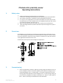 2
2
-
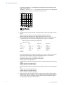 3
3
-
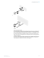 4
4
-
 5
5
-
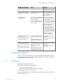 6
6
-
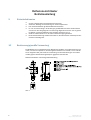 7
7
-
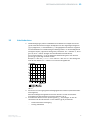 8
8
-
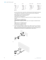 9
9
-
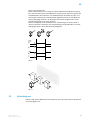 10
10
-
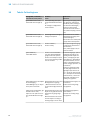 11
11
-
 12
12
-
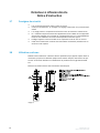 13
13
-
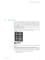 14
14
-
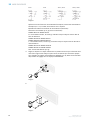 15
15
-
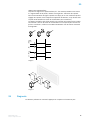 16
16
-
 17
17
-
 18
18
-
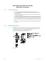 19
19
-
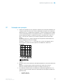 20
20
-
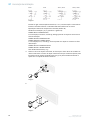 21
21
-
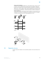 22
22
-
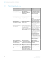 23
23
-
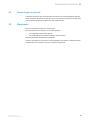 24
24
-
 25
25
-
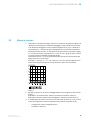 26
26
-
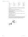 27
27
-
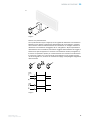 28
28
-
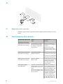 29
29
-
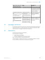 30
30
-
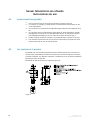 31
31
-
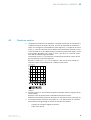 32
32
-
 33
33
-
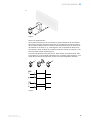 34
34
-
 35
35
-
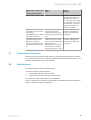 36
36
-
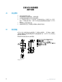 37
37
-
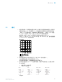 38
38
-
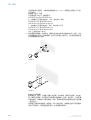 39
39
-
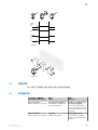 40
40
-
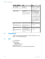 41
41
-
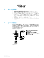 42
42
-
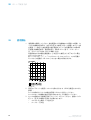 43
43
-
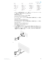 44
44
-
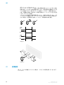 45
45
-
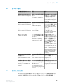 46
46
-
 47
47
-
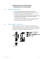 48
48
-
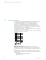 49
49
-
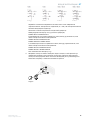 50
50
-
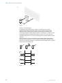 51
51
-
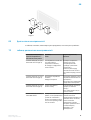 52
52
-
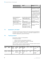 53
53
-
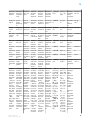 54
54
-
 55
55


SICK WTB4S-3 focused potentiometer Instrucciones de operación
- Tipo
- Instrucciones de operación
en otros idiomas
- français: SICK WTB4S-3 focused potentiometer Mode d'emploi
- italiano: SICK WTB4S-3 focused potentiometer Istruzioni per l'uso
- English: SICK WTB4S-3 focused potentiometer Operating instructions
- português: SICK WTB4S-3 focused potentiometer Instruções de operação
- 日本語: SICK WTB4S-3 focused potentiometer 取扱説明書
Artículos relacionados
-
SICK WTB4S-3 Teach-in focused Instrucciones de operación
-
-
SICK WT100-2 energetic Instrucciones de operación
-
-
-
-
-
-
-