INSTALLATION AND SERVICE MUST BE PERFORMED BY
A QUALIFIED INSTALLER.
IMPORTANT: SAVE FOR LOCAL ELECTRICAL INSPECTOR'S USE.
READ AND SAVE THESE INSTRUCTIONS FOR FUTURE REFERENCE.
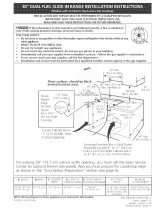
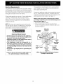
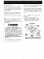
Shave Raised
EdgeToClear
30" (76.2 crn)
Wide Cooktop Rim
1-1/2" Max.
(3.8 cm Max.)
30"
(76.2 cm Min.)
(76.2 cm Min.) _ --
18" Min.
(4._ Min.)
Locate
Cabinet Doors
1" Min. from
Cut-Out
Opening
*Note:
29" (73,7 cm)
Wide Opening
For Overlapping
Cooktop And
Built-ln Look
Grounded Junction Box
in adjoining cabinet
Do not pinch the power supply cord between the range
and the wall,
Do not seal the range to the side cabinets,
24" Min.
(61 cm Min.)
Smoothtop Models
ANTI-TIP
AT REAR OF RANGE
48" (122 cm) _
NOTE: Two sets of holes are provided
under anti-tip bracket. Bracket is
attached in the upper hole position at
the factory.
29" (73.7 cm) 21 3/4" (55.2cm) 29" (73.7cm)
*NOTE: Allow at least 20" (50,1 cm) clearance for door
depth when it isopen.
**NOTE: 24" (61 cm) minimum clearance between the
cooktop and the bottom of the cabinet when the bottom
of wood or metal cabinet is protected by not lessthan 1/
4" (0.64 cm) flame retardant millboard covered with not
less than No. 28 MSG sheet metal, 0.015" (0,4 mm)
stainless steel, 0.024" (0,6 mm) aluminum, or 0.020" (0.5
mm) copper,
26" _1 1_1/2"
• (66.4 cm) ,I _.(3.9 ca)
2 -1/2" r--
29-3!6"
(74,6 cm)
30" (76.2 cm) minimum clearance when the cabinet is
unprotected,
22 7/8"_
58.1 cm
1
i
FRONT
OF
CABINET
_1 1/8"
(45.7 cm)
BRe_
* Door open
(see note)
---...... ;.<
Figure 1
_Recycled paper
PIN 318201602 (0103) Rev.A
English - pages 1-6
Espar_ol- p4ginas 7-12

Important Notes to the Installer
1, Readall instructions contained in these installation
instructions before installing range,
2, Remove all packing material from the oven before
connecting the electrical supply to the range,
3, Observe all governing codes and ordinances,
4, Besure to leavethese instructions with the consumer,
5, Oven door may be removed to facilitate installation.
6, Do not lift the range by the door handle,
Important Note to the Consumer
Keep these instructions with your owner's guide for future
reference.
IMPORTANT SAFETY
INSTRUCTIONS
• Be sure your range is installed and grounded
properly by a qualified installer or service
technician.
• This range must be electrically grounded in
accordance with local codes or, in their absence
with the National Electrical Code ANSI/NFPA No.
70--latest edition.
• The installation of appliances designed for
manufactured (mobile) home installation must conform
with Manufactured Home Construction and Safety
Standard, title 24CFR, part 3280 [Formerly the Federal
Standard for Mobile Home Construction and Safety,
title 24, HUD (part 280)] or when such standard is not
applicable, the Standard for Manufactured Home
Installation 1982 (Manufactured Home Sites,
Communities and Setups), ANSI Z225,1/NFPA 501A-
latest edition, or with local codes.
• Make sure the wall coverings around the range
can withstand the heat generated by the range.
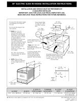
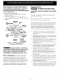
• All rangescan riD,
• Injury to Dersonscoula result
• Installanu-[ o ae_ce oacKeawlrn ranae
®
®
_To reduce the risk of
tipping of the range, [ne range mus[ De
secured by properly qs[aHea anu-_ Dscrews
for models wl[n cc e_ements.They are
located in a o_asucbag n[ne oven.For smoothtoD - adels, the
anti-tip bracKet located at the rear of the range fits under the
countertoo ano oreven[s ranoe from tiDoin J. Failure to insta
the anti-tip screws will allow the range to tip over if excessive
weight is placed on an open door or ifa child climbs upon it.
Serious injury might result from spilled hot liquids or from the
range itself.
• Before installing the range in an area covered
with linoleum or any other synthetic floor
covering, make sure the floor covering can
withstand heat at least 90°F above room
temperature without shrinking, warping or
discoloring. Do not install the range over carpeting
unless you place an insulating pad or sheet of 1/4"
thick plywood between the range and carpeting.
_ Never leave children alone or
unattended in the area where an appliance is in use.
As children grow, teach them the proper, safe use of all
appliances. Never leave the oven door open when the
range is unattended.
Stepping, leaning or sitting on the
door of this range can result in serious injuries and
can also cause damage to the range.
• Do not store items of interest to children in the
cabinets above the range. Children could be seriously
burned climbing on the range to reach items.
• To eliminate the need to reach over the surface
units, cabinet storage space above the units
should be avoided.
• Do not use the oven as a storage space. This
creates a potentially hazardous situation.
• Never use your range for warming or heating the
room. Prolonged use of the range without adequate
ventilation can be dangerous.
• Do not store or use gasoline or other flammable
vapors and liquids near this or any other
appliance. Explosions or fires could result.
• Reset all controls to the "off" position after using
a programmable timing operation.
FOR MODELS WITH SELF-CLEANFEATURE:
• Remove broiler pan, food and other utensils
before self-cleaning the oven. Wipe up excess
spillage. Follow the precleaning instructions in the Use
and Care Guide,
2

Electrical Requirements
This appliance must be supplied with the proper voltage
and frequency, and connected to an individual, properly
grounded branch circuit, protected by a circuit breaker or
fuse, having amperage as noted on the rating plate (the
rating plate is located on the oven frame).
If local codes permit, you can use a 3-wire single phase
120/208 or 120/240 Volt, 60Hz AC only electrical
system. If you connect to aluminum wiring, properly
installed connectors approved for use with aluminum
wiring must be use.
NOTE: Wire sizes and connections must conform with
the fuse size and rating of the appliance in accordance
with the National Electrical Code ANSI/NFPA No. 70-
latest edition, and local codes and ordinances.
Electrical Shock Hazard
, Electrical ground is required on this appliance.
, Do not connect to the electrical supply until
appliance is permanently grounded.
, Disconnect power to the junction box before
making the electrical connection.
, This appliance must be connected to a
grounded, metallic, permanent wiring system,
or a grounding connector should be connected
to the grounding terminal or wire lead on the
appliance.
, Do not use a gas supply line for grounding the
appliance.
Failure to do any of the above could result in a
fire, personal injury or electrical shock.
This appliance is manufactured with a neutral (white)
power supply wire and a cabinet-connected green (or
bare copper) grounding wire.
Connect the appliance cable to the junction box through
the U,L.-listed conduit connector, Complete electrical
connection according to local codes and ordinances. (For
preferredjunction box location, see Figure 1,)
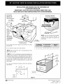
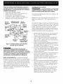
Where local codes permit connecting the cabinet-
grounding conductor to the neutral (white)junction
box wire (see Figure 2)
1. Disconnect the power supply.
2, In the circuit breaker, fuse box orjunction box:
connect the appliance and the residence cable wires
asshown in figure 2,
White Wire
(Neutral)
Cablefrom
Residence
Wires I
Box
(Neutral)
Green U.L.-listed
(or Bare Copper) Conduit
Wire Cable from Connector
Range (or CSA listed)
Figure 2
3-Wire (Grounded Neutral) Electrical System
(Example: Junction Box)
3

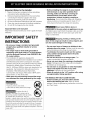
When connecting to a 4-wire electrical system,
when installing in a mobile home, or when local
codes DO NOT permit connecting the cabinet-
grounding conductor to the neutral (white)junction
box wire (see Figure 3)
1, Disconnect the power supply.
2, Separate the green (or bare copper) and white
appliance cable wires,
3, In the circuit breaker, fuse box or junction box:
connect appliance and residence cable wires as shown
in figure 3.
Cable from
Green Residence Junction
(or Bare Copper) Box
White Wire
Green
(or Bare Copper) White Wire
Wire (Neutral)
Cable from Conduit
Appliance Connector
(or CSA listed)
Figure 3 - 4-Wire Electrical System
(Example: Junction Box)
Improper connection of aluminum
house wiring to copper leads can result in a short
circuit or fire. Use only connectors designed for
joining copper to aluminum, and follow the
manufacturer's recommended procedure closely.
NOTE TO ELECTRICIAN: The armored cable leads
supplied with this appliance are UL-recognized for
connection to larger gauge household wiring. The
insulation of the leads is rated at temperatures much
higher than the temperature rating of household wiring,
The current carrying capacity of the conductor is
governed by the temperature rating of the insulation
around the wire, rather than the wire gauge alone.
Range Installation
The electrical power to the range
must be shut off while line connections are being
made. Failure to do so could result in serious injury
or death.
This range isdesigned to hang from the countertop, it
does not rest on the floor.
Be sure the bottom of any wall cabinets are a minimum
of 30" (76,2 cm) above the rangetop area,
To eliminate the hazard or reaching over heated surface
units, cabinet storage space located above the surface
units should be avoided. If cabinet storage isto be
provided, the hazard can be reduced by installing a
range hood that projects horizontally a minimum of 5"
(12.7 cm) beyond the bottom front edge of the cabinets.
1, Install base cabinets 29" (73,7 cm) apart, and be
sure they are plumb and level before attaching to
countertop.
2, Cut countertop exactly as shown in Figure 1. Shave
raised edge level to clear 30" (76,2 cm) wide rim on
rolled edge styled countertops,
3, Install the wiring,junction box in an adjoining cabinet
or under the floor (range has 48"/122 cm of
conduit), Cut 1-1/4" (3.2 cm) hole to bring conduit
to the,junction box.
4, Pushthe electric conduit through the hole and attach
it to the junction box, Leave enough slack in the
conduit to allow the range to be pulled forward
several inches for service if necessary,
5, Oven door is heavy. It is advisable to remove door
and eliminate its weight as range is lifted into
position, See oven door removal instructions in the
Use and Care Guide, Lift the range into position on
the countertop.
6, This range may be equipped with an anti-tip bracket
attached to the back of the range with two screws,
If countertop thickness is greater than 1/2" (1,3 cm),
relocate anti-tip bracket to the lower position 1/4"
(6.4 mm) below (see Figure 1),
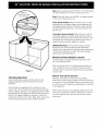
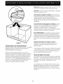
7, Ranges with a lift-up cooktop have 4 anti-tip screws
included in the literature pack (see Figure 4), Lift the
countertop and secure range burner box to cabinet
with these screws to prevent range from tipping.
4

)
Figure 4
Checking Operation
Some models have manual controls. Refer to the
Owner's Guide and check all controls for correct
operation.
Some models are equipped with an electronic oven
control. Each of the functions has been factory checked
before shipping. However, it issuggested that you verify
the operation of the electronic oven controls once more.
Refer to the Owner's Guide for operation. Follow the
instructions for the Clock, Timer, Bake, Broil, Convection
(some models) and Clean (some models) functions.
Bake-After setting the oven to 350°F (177°C) for baking,
the lower element in the oven should become red.
Broil-When the oven is set to BROIL,the upper element
in the oven should become red.
Clean (some models)-When the oven is set for a self-
cleaning cycle, the upper element should become red
during the preheat portion of the cycle. After reaching
the self-cleaning temperature, the lower element will
become red.
Convection (some models)-When the oven is set for
convection baking or roasting, both elements cycle on
and off alternately and the convection fan will turn. The
convection fan will stop turning when the oven door is
opened during convection baking or roasting.
IMPORTANT NOTE: A fan inside the upper rear part
above the oven (some models) provides additional
cooling of the oven electrical and electronic components.
The fan will continue to run after the oven has been
operating at high temperatures.
Model and Serial Number Location
The serial plate is located along the side of the oven
door in the open position.
When ordering parts for or making inquires about your
oven, always be sure to include the model and serial
numbers and a lot number or letter from the serial plate
on your oven.
Before You Call for Service
Read the Avoid Service Checklist and operating
instructions in your Owner's Guide. It may save you time
and expense. The list includes common occurrences that
are not the result of defective workmanship or materials
in this appliance.
Refer to the warranty in your Owner's Guide for our toll-
free service number and address. Please call or write if
you have inquiries about your product and/or need to
order parts.
5

Notes
6

LA INSTALACION Y EL SERVICIO DEBEN SER EFECTUADOS POR
UN INSTALADOR CALIFICADO.
IMPORTANTE: GUARDE ESTAS INSTRUCCIONES PARA USO DEL
INSPECTOR LOCAL DE ELECTRICIDAD.
LEA Y GUARDE ESTAS INSTRUCCIONES PARA REFERENCIA FUTURA.
Acepille el borde subido a
ue deje espacio para un
borde de 30 (76.2 cm) de
anchura de estufa.
1-1/2" Max.
(3.8 cm Max.)
30"
1(76.2cmMin.)
(76.2 cm Min3 _ --
18" Min.
(4._ Min.)
biue las
mnimodel de
la abertura,
*Not : Abertura
de 29" (73.7 cm) de
anchura para la
superficie de
estufa traslapada
la aparencia de
estar incorporada.
La caja de empalmes de
conexi n con [a tierra
No pellizque el cordon electrico entre la estufa y la
pared.
No selle la estufa a los armarios de lado.
*NOTA: Deje por los 20" (50.1 cm) de espacio libre para
la profundidad de la puerta cuando esta abierta.
**NOTA: Un espacio minimo de 24" (61 cm) entre la
superficie de la estura y el rondo del armario cuando el
rondo del armario de madera o metal esta protegido por
no menos de 1/4" (0.64 cm) de madera resistente al
fuego cubierta por una lamina metalica de MSG, n0mero
28, 0.015" (0.4 mm) de acero inoxidable, 0.024" (0.6
mm) de aluminio, O0.02" (0.5 mm) de cobre.
Un espacio minimo de 30" (76.2 cm) cuando el armario
no esta protegido.
24" Min.
(61 cm Min.)
Modelos de superficie lisa
SOPORTE ANTIVUELCO
AL FONDO DE LA ESTUFA
48" (122 cm) _
Cable
NOTA: Hay dos juegos de agujeros
debajo del soporLeantivuelco. ElsoporLe
viene colocado, desde la rabrica, en el
agujero superior.
29" (73.7 cm) 21 3/4" (55.2 cm) 29" (73.7 cm)
26'! 1_1/2"
cm)
29-3/8"
(74,6 cm)
PARTE
DELANTERA
DEL
ARMARIO
22 7/8"_
58.1 cm
iiiiiiiiiiiiiiiiiiiiiiiiiiiiiiiiiiiiiiiiiiiiiiiij _;i;i;i;i;i;i;ii
ml 1/8"
(45.7cm)
BR_
_ Papel recidado
P/N 318201602 (0103) Rev.A
English - pages 1-6
Espar_ol- paginas 7-12

Notas importantes para el instalador
1. Leatodas las instrucciones contenidas en este manual
antes de instalar la estufa.
2. Saque todo el material usado en el embalaje del
compartimiento del homo antes de conectar el
suministro electrico a la estufa.
3. Observe todos los cOdigosy reglamentos pertinentes.
4. Deje estas instrucciones con el comprador.
5. Parafacilitar la instalaciOn puede quitarse la puerta
del homo.
6. No levante la estufa pot la manija de la puerta.
Nora importante para el consumidor
Conserve estas instruccionesy el Manual del Usuario para
referencia futura.
IMPORTANTES
INSTRUCCIONES DE
SEGURIDAD
• Aseg,',rese que su cocina est_ instalada y
conectada adecuadamente a tierra per un
instalador calificado o un t_cnico de servicio.
• Esta cocina debe ser conectada a tierra
el_ctricamente de acuerdo con los cbdigos
locales, o de no existir, con la National Electrical
Code ANSI/NFPA No.70- ttltirna edicibn.
• La instalaciOn de electrodom_sticos destinados para
casas (movibles) deben conformarse con la
Manufactured Home Construction and Safety
Standard, titulo 24CFR, parte 3280 [antiguamente la
Federal Standard for Mobile Home Construction and
Safety, tltulo 24, HUD (parte 280)] o cuando este
cOdigo no se aplica, la Standard for
xxx Z
• Todaslascodnas pueden inclinarse. _ "_._'f_- _
* Estopuede provocar lesionespersonales. _ _ I
, Instaleel dispositivo anti-inclinacion que
vienecon lacocina.
Parareducirel riesgode r_lll_, _
que sevuelqueIa estufa, hayque asegurarla _,_
adecuadamentecolocandolelos soportes _--_
antivuelcoque se proporcionan, para
modeloscon elementosde bobina. Las
piezasseencuentranen un sacode plasticoen el homo. Para
modelosde tapa lisa,el soporte antivuelcoque seencuentra
al rondo de la estufacabedebajodel tablero y evita que la
estufasevuelque. Si no seinstalanlostornillos antivuelco, la
estufapodra volcarses! sele pone pesoexcesivoenla puerta
abiertao siun nirio sesubea ella.Estopuederesultar en
dano sedosi liquidoscalientessederramarano si la estufase
cayera.
Manufactured Home Installation 1982 (Manufactured
Home sites, communities and setups) ; ANSIZ225.1/
NFPA 501A- ultima ediciOn o con cOdigos locales.
• Asegdrese que el empapelado de pared alrededor
de la cocina pueda resistir el calor generado por
la cocina.
• Antes de instalar la cocina en una brea cubierta
de linoleo o cualquier otro revestidor de piso
sint_tico, aseg,',rese que _ste pueda resistir al
menos 90°F sobre la temperatura de la pieza sin
encogerse, ladearse o descolorisarse. No instale la
cocina encima de una alfombra a menos que coloque
una placa de aislamineto o una plancha de 1/4" de
madera entre la cocina y el alfombrado.
Ilrlv=_,_,A=:ll=:[_r=!Nunca deje a los niftos solos o sin
cuidado en el area donde el electrodomestico etb en
uso. A medida que los nihos crezcan, enseneles el uso
adecuado de los electrodomesticos.Nunca deje la puerta
del homo abierta cuando la cocina este sin supervision.
Pisar, apoyarse o sentarse en las
puertas o los cajones de la cocina pueden causar
graves herridas y tambi_n dahar la cocina.
• No coloque cosas que atraigan a los ni_os sobre
los gabinetes encima de la cocina. Los nihos
podrian sufrir quemaduras tratando de alcanzarlos.
• Para eliminar la necesidad de ir a buscar algo por
encima de los quemadores, no coloque gabinetes
por encima de _stos.
• No use el homo como espacio de
almacenamiento. Estocrea una situaciOn muy
peligrosa.
• Nunca use su cocina para calentar la pieza. El uso
prolongado de la cocina sin ventilaciOn adecuada
puede set peligroso.
• No guarde o use gasolina u otros vapores
inflamables y liquidos cerca de _ste o cualquier
otro el_ctrodom_stico. Esto podria causar una
explosion o un incendio.
• Vuelva a programar todos los controles a la
posicibn "off" (apagado) despu_s de haber
utilizado el conteo contador autorn_tico.
PARALOS MODELOS CON AUTO-LIMPIEZA:
• Retire el rostisador, la comida y otros utensilios
antes de auto-limpiar el homo. Limpie todo exceso
de derrames. Siga las instrucciones para la pre-
limpieza en el Manual del usuario.
8

Requisitos el_ctricos
Este artefacto debe ser suministrado con e! voltaje y la
frecuencia adecuados, y conectado a un circuito
individual correctamente puesto a tierra, protegido por
un cortacircuitos o un fusible con el amperio anotado en
la placa de calificaciOn (la placa se encuentra en el
armazOn del homo).
Si los cOdigos locales Io permiten, se puede usar un
sistema el_ctrico de 3 alambres de fase tinica de 120/
208 O 120/240 voltios, 60Hz AC solamente. Sise
conecta a un alambrado de aluminio, tienen que usarse
conectores bien instalados y aprobados para uso con el
alambrado de aluminio.
NOTA: Lostamahos de alambres y conectores deben
conformarse con el tamano del fusible y la calificaciOn
del artefacto de acuerdo con el COdigo Electrico
Nacional ANSI/NFPA No. 70-tiltima ediciOn y los cOdigos
y ordenanzas locales.
Riesgo de choque electrico
• Una puesta a tierra se require en este aparato.
• No Io conecte a la corriente electrico hasta que
el aparato haya sido puesto a tierra.
• Desconecte la corriente el_ctrica a la caja de
empalmes antes de hacer la conexion electrica.
• Este aparato debe estar conectado con un
sistema de alambres puesto en tierra, met_ilico
y permanente o un conector de pueta a tierre
debe conectarse al terminal de puesta a tierra
o el alambre conductor en al aparato.
• No utilice el suministro de gas para hacer la
puesta a tierra.
La falta de hacer cualquier de las cosas arriba
podrla resultar en un incendio, choque electrico
o lesiones personales.
Este aparato est8 fabricado con un alambre electrico
neutro (blanco) y un alambre verde (o alambre pelado)
de puesta a tierra conectado al gabinete.
Conecte el cable del aparato a la caja de empalmes por
medio del conductor de union listado-UL Complete la
conexiOn segun los cOdigos y ordenanzas locales. (Para
la ubicaciOn preferida de la caja de empalmes, v_ase la
Figura 1.)
Donde los cOdigos locales permitan la conexiOn del
conductor de gabinete-puesta a tierra con el
alambre neutro (blanco) de la caja de empalmes
(vea figura 2)
1. Desconecte la fuente de alimentaciOn.
2. En el disyuntor, caja de fusibles o la caja de
distribuciOn: conecte el artefacto y los cables de la
residencia como se muestra en la figura 2.
Alambre
Blanco
(Neutro)
Alambres--
Cable de la fuente
de alimentaci6n
negros
ja de
Blanco
Alambres (Neutm)
desnudos Conductor de
unibn listado-UL
o verdes Cable de la (listado-CSA)
estufa
Figura 2 - Sistema el_ctrico (ejemplo: caja de
empalmes) de 3 alambres (a tierra neutral)
9

Donde los cbdigos locales NO permitan conectar el
conductor de puesta a tierra del el_ctrodom_stico al
neutral (blanco), o si est_ conectado con un sistema a
4 alambres (vea figura 3):
1. Desconecte el suministro electrico
2. Separe el alambre verde (o cobre desnudo) y el
alambre blanco del electrodomestico.
3. En el disyuntor, caja de fusibles o la caja de
distribuciOn: conecte el artefacto y los cables de la
residencia como se muestra en la figura 3.
Alambre Cable de la fuente Caja de
desnudo o de alimentaci6n
verde
Alambre
Alambres (Neutro)
ojos
Alambres
Alambres
desnudos o Alambre
verdes Blanco
(Neutro)
Cable de la
estufa
unibn listado-UL
(o listado-CSA)
Figura 3 - Sistema el_ctrico de 4 alambres
(ejemplo caja de empalme)
Una conexi6n incorrecta del
alambrado de aluminio con los conductores de
cobre puede resultar en un cortacircuito o incendio.
Use solamente los conectores disefiados parajuntar
el cobre con el aluminio y siga exactamente el
procedimiento recomendado pot el fabricante.
NOTA AL ELECTRICISTA: Los conductores de cable
blindados provistos con este artefacto son aprobados por
UL para la conexiOn al alambrado de casa de un calibre
mayor. Elaislamiento de los conductores est8 calificado
para temperaturas m_s altas que las del alambrado de la
casa. La capacidad de corriente del conductor est8
gobernada por la calificaciOn de la temperatura del
aislamiento alrededor del alambre en vez de solamente
el calibre del alambre.
Instalacibn de la estufa
La corriente el_ctrica a la estufa debe
apagarse mientras se hagan las conexiones. Si no se
hace esto puede provocar dafto serio o muerte.
Estaestufa est_ disenada para colocarse en el tablero. No
se sostiene en el piso.
Aseg0rese de que la parte baja de los armarios este a una
altura de un minimo de 30" (76.2 cm) del _rea de la
estufa.
Paraeliminar el peligro de tenet que extender el brazo por
encima de la superficie caliente de la estufa, se debe evitar
la instalaciOn de gabinetes por encima de ella. Si hay que
instalar gabinetes por encima de la estufa, se puede
reducir el riesgo instalando un ventilador de estufa que se
proyecte horizontalmente un minimo de 5" (12.7 cm) mSs
all_ del borde delantero inferior de los gabinetes.
1. Instale los gabinetes inferiores con una separaciOn de
29" (73.7 cm), y asegurese de que esten a plomo y
nivelados antes de unirlos al tablero.
2. Corte el tablero exactamente como se muestra en la
Figura 1. Cepille a nivel el borde levantado, para
para que libre un filete de 30" (76.2 cm) de ancho en
tableros con bordes laminados.
3. Instale la caja de conexiones electricas en un armario
adjunto o debajo del piso (la estufa tiene 48"/122 cm
de alambre). Abra un agujero de 1-1/4" (3.2 cm) para
traer el alambre hasta la caja de conexiones.
4. Introduzca el alambre electrico pot el agujero y fijelo a
la caja. Deje suficiente alambre flojo para permitir que
la estufa sejale hacia delante varias pulgadas si fuera
necesado dade servicio.
5. La puerta del homo es pesada. Se recomienda que se
quite la puerta y elimine su peso mientras se est8
colocando la estufa en su posiciOn. Vealas
instrucciones sobre cOmo quita la puerta de la estufa.
Levante y coloque la estufa en su posiciOn en el
tablero.
6. Estaestufa puede traer soportes antivuelco, fijados al
dorso de la estufa con dos tornillos. Siel grueso del
tablero es mSsde 112" (1.3 cm), coloque de nuevo el
soporte antivuelco en la posiciOn mSs baja, de 1/4"
(6.4 mm). (Vea Figura !).
7. Lasestufas con una tapa para cocinar que se levanta
tienen 4tornillos antivuelco que seincluyen en el
paquete de instrucciones (vea Figura 4). Levante la
tapa y fije la caja de hornillas al armario con estos
tornillos para evitar que la estufa se vuelque.
lO

)
Figura 4
Comprobacibn del funcionamiento
Algunos modelos tienen controles manuales. Consulte el
Manual del Usuario y asegtirese de que todos los
controles funcionen correctamente,
Algunos modelos estan equipados con un control
electrOnico, Cada funciOn ha sido probada en la fabrica
antes del transporte, Sin embargo, sugerimos que Ud.
verifique el funcionamiento de los controles del homo
una vez mSs, Vdase el Manual del Usuario para la
operaciOn. Siga las instrucciones para el reloj minutero,
Cocer, Asar, ConvecciOn (algunos modelos) y las
funciones de limpieza (algunos modelos),
Bake/Cocer-Despues de poner el homo a 350°F (177°C)
para cocer, el elemento inferior debe ponerse rojo,
Broil/Asar-Cuando est8 puesto para BROIL,el elemento
superior sedebe porter rojo.
Clean/Limpieza (algunos modelos)-Cuando el homo
est8 puesto para un ciclo de autoqimpieza, el elemento
superior se pondr8 rojo durante el perlodo de
precalentamiento del ciclo. Despues de alcanzar la
temperatura de autoqimpieza, el elemento inferior se
pondra rojo.
Convection/Convecci6n (algunos modelos)--Cuando
el homo se pone a CONV/BAKE los dos elementos se
encienden y se apagan alternando en un ciclo y el
ventilador se pone en marcha, El ventilador de
convecciOn se parar_ cuando se abre la puerta del homo
durante el cocido o el asado por convecciOn.
NOTA IMPORTANTE: Un ventilador en la parte superior
y atrSs, arriba del homo (algunos modelos) provee un
enfriamiento adicional para los componentes electricos y
electrOnicos del horno. Elventilador seguir8 en marcha
cuando el homo ha estado operando alas temperaturas
altas.
UbicaciOn del ndmero de modelo y de serie
La placa con el nLimero de modelo y de serie est8
ubicada en el borde de la puerta del homo en la
posiciOn abierta,
Cuando haga pedidos de repuestos o solicite informaciOn
con respecto a su homo, este siempre segro de incluir el
numero de modelo y de serie y el ntimero o letra del
lore de la placa de serie de su homo,
Antes de Ilamar al servicio
Lea la secciOn Lista de Control de Averias en su Manual
del Usuario. Esto le podra ahorrar tiempo y gastos, Esta
lista incluye ocurrencias comunes que no son el resultado
de defectos de materiales o fabricaciOn de este
artefacto.
Lea la garantia y la informaciOn sobre el servicio en su
Manual del Usuario para obtener el nOmero de tel_fono
gratuito y la dirreciOn del servicio, Por favor Ilame o
escriba si tiene preguntas acerca de su homo o necesita
repuestos,
11

Notas
12
-
 1
1
-
 2
2
-
 3
3
-
 4
4
-
 5
5
-
 6
6
-
 7
7
-
 8
8
-
 9
9
-
 10
10
-
 11
11
-
 12
12


Frigidaire FED300ASD Guía de instalación
- Categoría
- Hornos
- Tipo
- Guía de instalación