Craftsman 82139 El manual del propietario
- Categoría
- Multimetros
- Tipo
- El manual del propietario

Owner's Manual
AutoRanging
Digital MultiMeter
Model No.
82139
I QQ O 1!
G
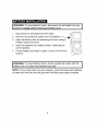
CAUTION: Read, understand and
follow Safety Rules and Operating
Instructions in this manual before
using this product.
• Safety
• Operation
• Maintenance
• EspaSoI
© Sears, Roebuck and Co., Hoffman Estates, IL 60179 U.S.A.
www.craftsman.com 070606

IP':_:] II :[o] _l[o[o]_i / :1_i II
Page
Warranty 3
Safety Instructions 3
Safety Symbols 4
Control and Jacks 5
Symbols and Annunciators 5
Specifications 6
Battery Installation 9
Operating Instructions 10
AutoRanging/ManualRanging 10
Data Hold 10
Relative 11
DC Voltage Measurements 11
AC Voltage Measurements 12
DC Current Measurements 12
AC Current Measurements 13
Resistance Measurements 14
Continuity Check 14
Diode Test 15
Frequency and Duty Cycle Measurements 15
Capacitance Measurements 16
Temperature Measurements 16
Maintenance 17
Replacing Batteries 17
Replacing Fuses 18
Troubleshooting 19
Service and Parts 19

D]_I:lk'd:1:1:1 ill I IlVlVl:l:] :;:1_iI
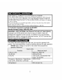
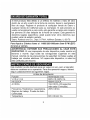
ONE YEAR FULL WARRANTY ON CRAFTSMAN MULTIMETER
If this CRAFTSMAN Multimeter fails to give complete satisfaction within one year
from the date of purchase, RETURN IT TO THE NEAREST SEARS STORE OR
OTHER CRAFTSMAN OUTLET IN THE UNITED STATES, and Sears will replace
it, free of charge.
This warranty gives you specific legal rights, and you may also have other rights
which vary from state to state.
Sears, Roebuck and Co., Dept. 817WA, Hoffman Estates, IL 60179
For Customer Assistance Call 9am-5 PM (EST)
Monday through Friday 1-888-326-1006
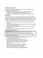
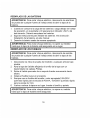
I WARNING: USE EXTREME CAUTION IN THE USE OF THIS DEVICE.
Improper use of this device can result in injury or death. Follow all
safeguards suggested in this manual. In addition to the normal safety
precautions used in working with electrical circuits. DO NOT service this
device if you are not qualified to do so.
,_:1_ :ii'| I_[.'t /:|l[it t[e] _[.1
This meter has been designed for safe use, but must be operated with
caution. The rules listed below must be carefully followed for safe operation.
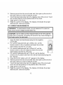
1. NEVER apply voltage or current to the meter that exceeds the
specified maximum:
Function
V DC or V AC
mA DC/AC
A DC/AC
Frequency, Resistance, Capacitance,
Duty Cycle, Diode test, Continuity
Temperature
Input Limits
Maximum Input
600V DC, 600V AC
400mA DC/AC
10A DC/AC (30 seconds max
every 15 minutes)
250V DC/AC
60V DC/24V AC

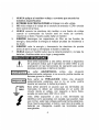
2. USEEXTREMECAUTIONwhen working with high voltages.
3. DO NOT measure voltage if the voltage on the "COM" input jack
exceeds 500V above earth ground.
4. NEVER connect the meter leads across a voltage source while the
function switch is in the current, resistance, or diode mode. Doing so
can damage the meter.
5. ALWAYS discharge filter capacitors in power supplies and disconnect
the power when making resistance or diode tests.
6. ALWAYS turn off the power and disconnect the test leads before
opening the doors to replace the fuse or batteries.
7. NEVER operate the meter unless the back cover and the battery and
fuse doors are in place and fastened securely.
ff.*1_1:11Ik'dl,.'b'd_v+I:[o] IB
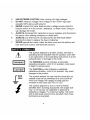
±
LWARN,NGJ
IcAuT,°Ni
F MAX
500V
This symbol adjacent to another symbol, terminal or
operating device indicates that the operator must refer
to an explanation in the Operating Instructions to avoid
personal injury or damage to the meter.
This WARNING symbol indicates a potentially
hazardous situation, which if not avoided, could result
in death or serious injury.
This CAUTION symbol indicates a potentially
hazardous situation, which if not avoided, may result
damage to the product.
This symbol advises the user that the terminal(s) so
marked must not be connected to a circuit point at
which the voltage with respect to earth ground
exceeds (in this case) 500 VAC or VDC.
This symbol adjacent to one or more terminals
identifies them as being associated with ranges that
may, in normal use, be subjected to particularly
hazardous voltages. For maximum safety, the meter
and its test leads should not be handled when these
terminals are energized.

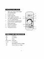
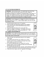
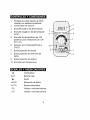
_To]_i / _To]iF.']r_*l_Ie]PF_*To_[(_
1. 4000 count Liquid Crystal Display
with symbolic signs
2. Function switch
3. Positive input jack
4. COM (negative) input jack
5. 10A (positive) input jack for 10A
DC or AC measurements
6. Continuity/Diode, Frequency/Duty
Cycle or AC/DC selection button.
7. Range pushbutton
8. Data Hold pushbutton
9. Relative pushbutton
10. Temperature socket
7
6
./,8
_9
_2
3
4
H-" • i_. II i_. _. _. i • _
o))) Continuity
BAT Low Battery
-IN Diode
DATA HOLD Data Hold
AUTO AutoRanging
AC Alternating Current or Voltage
DC Direct Current or Voltage

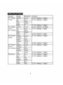
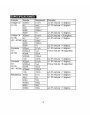
,t".,1_[l! IiI [___1t[.] _B
Function
DC Voltage
(V DC)
AC Voltage
(V AC)
(40 - 400Hz)
DC Current
(A DC)
AC Current
(A AC)
(40 - 400Hz)
Resistance
Range
400mY
4V
40V
400V
600V
400mY
4V
40V
400V
600V
400HA
4000HA
40mA
400mA
10A
400HA
4000HA
40mA
400mA
10A
400O-
4k£-.)
40k£-._
400k£-._
4M_.)
40M_.)
Resolution
0.1mV
lmV
10mV
100mV
1V
0.1mV
lmV
10mV
100mV
1V
0.1 HA
1HA
10HA
100HA
10mA
0.1 HA
1HA
10HA
100HA
10mA
0.1£-._
1£-._
10£-._
100£-._
lk£-._
10k£-._
Accuracy
_+(0.5%reading + 2 digits)
_+(1.0%reading + 2 digits)
_+(1.5%reading + 2 digits)
_+(2.0%reading + 30 digits)
_+(1.5%reading + 3 digits
_+(2.0%reading + 4 digits
_+(1.5%reading + 3 digits)
_+(2.5%reading + 5 digits)
_+(1.8%reading + 5 digits)
_+(3.0%reading + 7 digits)
_+(1.2%reading + 4 digits)
_+(1.2%reading + 2 digits)
_+(2.0%reading + 3 digits)

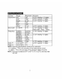
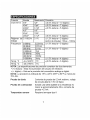
Function Range
Capacitance4nF
40nF
400nF
4IJF
40,uF
200,uF
DutyCycle0.1-99.9%
Frequency9.999Hz
99.99Hz
999.9Hz
9.999kHz
99.99kHz
999.9kHz
9.999MHz
Temp°F -4to1400°F
Temp°C -20to760°C
Resolution
lpF
10pF
0.1nF
lnF
10nF
0.1!iF
0.1%
0.001Hz
0.01Hz
0.1Hz
1Hz
10Hz
100Hz
lkHz
1OF
1oc
Accuracy
_+(5.0%reading+10digits)
_+(5.0%reading+7digits)
_+(3.5%reading+5digits)
_+(5.0%reading+5digits)
_+(1.2%reading+2digits)
Pulsewidth:100!_s-100ms
_+(1.5%reading+5digits)
_+(1.2%reading+2digits)
_+(1.5%reading+4digits)
_+(3.0%reading+3digits)
NOTE:Accuracyspecificationsconsistoftwoelements:
•(%reading)- Thisistheaccuracyofthemeasurementcircuit.
•(+digits)- Thisistheaccuracyoftheanalogtodigitalconverter.
NOTE:Accuracyisstatedat65°Fto83°F(18°Cto28°C)andlessthan
70%RH.

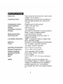
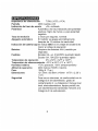
Diode Test
Continuity Check
Temperature sensor
Input Impedance
Display
Overrange indication
Polarity
Measurement Rate
Auto Power Off
Low Battery Indication
Batteries
Fuses
Operating Temperature
Storage Temperature
Relative Humidity
Operating Altitude
Weight
Size
Safety
Test current of 0.3mA maximum, open circuit
voltage 1.5V DC typical
Audible signal will sound if the resistance is
less than approximately 30£-._,test current
<0.7mA
Requires type K thermocouple
7.5M£-2(VDC and VAC)
4000 count LCD
"OL" is displayed
Automatic (no indication for positive polarity);
Minus (-) sign for negative polarity.
2 times per second, nominal
Meter automatically shuts down after 15
minutes of inactivity
"BAT" is displayed if battery voltage drops
below operating voltage
Requires two AAA batteries (sold separately)
mA, !_A ranges, 0.5A/250V fast blow
10A range, 10A/250V fast blow
32°F to 122°F (0°C to 50°C)
-4°F to 140°F (-20°C to 60°C)
<70% operating, <80% storage
2000 meters (7000ft.) maximum.
9.17 oz. (260g).
4.78" x 2.38" x 1.57" (121.5mm x 60.6mm x
40mm)
For indoor use and in accordance with
Overvoltage Category II, Pollution Degree 2.
Category II includes local level, appliance,
portable equipment, etc., with transient
overvoltages less than Overvoltage Category
III.

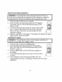
IWARNING:Toavoidelectricshock,disconnectthetestleadsfromany
sourceofvoltagebeforeremovingthebatterydoor.
1. Disconnectthetestleadsfromthemeter.
2. Removetheprotectiverubberboot(ifinstalled).---_-_
3. Openthebatterydoorbylooseningthescrewusinga
Phillipsheadscrewdriver.
4. Insertthebatteriesintobatteryholder,observingthe
correctpolarity.
5. Putthebatterydoorbackinplace.Securewiththetwo
screws.
I WARNING: To avoid electric shock, do not operate the meter until the I
battery door is in place and fastened securely.
I
NOTE: If your meter does not work properly, check the fuses and batteries
to make sure that they are still good and that they are properly inserted.

I ARNING: Risk of electrocution. High-voltage circuits, both AC and DC,
are very dangerous and should be measured with great care.
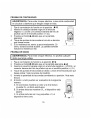
1. ALWAYS turn the function switch to the OFF position when the meter is
not in use. This meter has Auto OFF that automatically shuts the meter
OFF if 15 minutes elapse between uses.
2. If "OL" appears in the display during a measurement, the value exceeds
the range you have selected. Change to a higher range.
NOTE: On some low AC and DC voltage ranges, with the test leads not
connected to a device, the display may show a random, changing
reading. This is normal and is caused by the high-input sensitivity.
The reading will stabilize and give a proper measurement when
connected to a circuit.
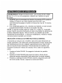
AUTORANGING / MANUALRANGING SELECTION
When the meter is first turned on, it automatically goes into AutoRanging.
This automatically selects the best range for the measurements being
made and is generally the best mode for most measurements. For
measurement situations requiring that a range be manually selected,
perform the following:
1. Press the RANGE button. The "AUTO" display indicator will turn off.
2. Press the RANGE button to step through the available ranges until you
select the range you want.
3. Press and hold the RANGE button for 2 seconds to exit the
ManualRanging mode and return to AutoRanging.
DATA HOLD
The Data Hold function allows the meter to "freeze" a measurement for
later reference.
1. Press the DATA HOLD button to "freeze" the reading on the indicator.
The indicator "HOLD" will appear in the display.
2. Press the DATA HOLD button to return to normal operation.
NOTE: The DATA HOLD function works in the FREQUENCY mode only
when a signal is present.
10

RELATIVE
The relative measurement feature allows you to make measurements
relative to a stored reference value. A reference voltage, current, etc. can
be stored and measurements made in comparison to that value. The
displayed value is the difference between the reference value and the
measured value.
1. Perform any measurement as described in the operating instructions.
2. Press the RELATIVE button to store the reading in the display and the
"REL" indicator will appear on the display.
3. The display will now indicate the difference between the stored value
and the measured value.
4. Press the RELATIVE button to return to normal operation.
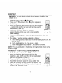
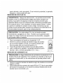
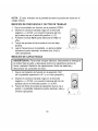
DC VOLTAGE MEASUREMENTS
I AUTION: Do not measure DC voltages if a motor on the circuit is I
being switched ON or OFF. Large voltage surges may occur that can
I
damage the meter.
1. Set the function switch to the V DC position CmV" will
appear in the display).
2. Insert the black test lead banana plug into the negative
(COM) jack and the red test lead banana plug into the
positive (V) jack.
3. Touch the test probe tips to the circuit under test. Be
sure to observe the correct polarity (red lead to
positive, black lead to negative).
4. Read the voltage in the display. The display will
indicate the proper decimal point and value. If the
polarity is reversed, the display will show (-) minus before the value.
11

AC VOLTAGE MEASUREMENTS
WARNING: Risk of Electrocution. The probe tips may not be long
enough to contact the live parts inside some 240V outlets for
appliances because the contacts are recessed deep in the outlets. As
a result, the reading may show 0 volts when the outlet actually has
voltage on it. Make sure the probe tips are touching the metal contacts
inside the outlet before assuming that no voltage is present.
CAUTION: Do not measure AC voltages if a motor on the circuit is
being switched ON or OFF. Large voltage surges may occur that can
damage the meter.
1. Set the function switch to the V AC position.
2. Insert the black test lead banana plug into the negative
(COM) jack and the red test lead banana plug into the
positive (V) jack.
3. Touch the test probe tips to the circuit under test.
4. Read the voltage in the display. The display will indicate
the proper decimal point, value and symbol (AC, V, etc.).
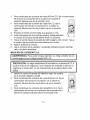
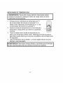
DC CURRENT MEASUREMENTS
I CAUTION: DO not make current measurements on the 10A scale for I
I
longer than 30 seconds. Exceeding 30 seconds may cause damage to
the meter and/or the test leads.
1. Insert the black test lead banana plug into the negative
(COM) jack.
2. For current measurements up to 4000!_A DC, set the
function switch to the !_A position and insert the red test
lead banana plug into the (!_A)jack.
3. For current measurements up to 400mA DC, set the
function switch to the mA range and insert the red test lead
banana plug into the (mA) jack.
4. For current measurements up to 10A DC, set the function switch to the
A position and insert the red test lead banana plug into the 10A jack.
5. Press the AC/DC button until "DC" appears in the display.
12

6. Removepowerfromthecircuitundertest,thenopenupthecircuitat
thepointwhereyouwishtomeasurecurrent.
7. Touchtheblacktestprobetiptothenegativesideofthecircuit.Touch
theredtestprobetiptothepositivesideofthecircuit.
8. Applypowertothecircuit.
9. Readthecurrentinthedisplay.Thedisplaywillindicatetheproper
decimalpoint,valueandsymbol.
AC CURRENT MEASUREMENTS
I ARNING: To avoid electric shock, do not measure AC current on
any circuit whose voltage exceeds 250V AC.
I
I AUTION: Do not make current measurements on the 10A scale for
longer than 30 seconds. Exceeding 30 seconds may cause damage to
the meter and/or the test leads.
1. Insert the black test lead banana plug into the negative
(COM) jack.
2. For current measurements up to 4000!_A AC, set the
function switch to the !_A position and insert the red test
lead banana plug into the (!_A)jack.
3. For current measurements up to 400mA AC, set the
function switch to the mA range and insert the red test
lead banana plug into the (mA) jack.
4. For current measurements up to 10A AC, set the function
switch to the A position and insert the red test lead banana plug into
the 10A jack.
5. Press the AC/DC button until "AC" appears in the display.
6. Remove power from the circuit under test, then open up the circuit at
the point where you wish to measure current.
7. Touch the black test probe tip to the negative side of the circuit and
touch the red test probe tip to the positive side of the circuit.
8. Apply power to the circuit.
9. Read the current in the display. The display will indicate the proper
decimal point, value and symbol.
I
13

RESISTANCE MEASUREMENTS
I ARNING: TO avoid electric shock, disconnect power to the unit I
under test and discharge all capacitors before taking any resistance
I
measurements. Remove the batteries and unplug the line cords.
1. Set the function switch to the £-2position.
2. Insert the black test lead banana plug into the negative
(COM) jack and the red test lead banana plug into the
positive £-2jack.
3. Touch the test probe tips across the circuit or part under
test. It is best to disconnect one side of the part under
test so the rest of the circuit will not interfere with the
resistance reading.
4. Read the resistance in the display. The display will indicate the proper
decimal point, value and symbol.
CONTINUITY CHECK
I WARNING: To avoid electric shock, never measure continuity on I
circuits or wires that have voltage on them.
I
1. Set the function switch to the-)l-o)))position.
2. Insert the black lead banana plug into the negative (-)
jack (COM) and the red test lead banana plug into the
positive (+) jack (£-2).
3. Press the _-))) button until the "))) symbol appears in
the display.
4. Touch the test probe tips to the circuit or wire you wish
to check.
5. If the resistance is less than approximately 30£-2,the
audible signal will sound. The display will also show the actual
resistance.
14

DIODETEST
I ARNING: To avoid electric shock, do not test any diode that has
voltage on it.
1. Set the function switch to-_-))_)position.
2. Press the -)1--))_)button until the _ symbol appears in
the display.
3. Insert the black test lead banana plug into the negative
(-) jack (COM) and the red test lead banana plug into
the positive (+) jack (_-.)).
4. Touch the test probe tips to the diode or
semiconductor junction you wish to test. Note the
meter reading.
5. Reverse the probe polarity by switching probe position. Note this
reading.
6. The diode or junction can be evaluated as follows:
A. If one reading shows a value and the other reading shows OL, the
diode is good.
B. If both readings show OL, the device is open.
C. If both readings are very small or 0, the device is shorted.
NOTE: The value indicated in the display during the diode check is the
forward voltage.
FREQUENCY or DUTY CYCLE MEASUREMENTS
1. Set the function switch to the FREQ position.
2. Insert the black test lead banana plug into the
negative (-) jack (COM) and the red test lead banana
plug into the positive (+) jack (F).
3. Press the Hz/% key to select "Hz" or "%".
4. Touch the test probe tips to the circuit under test.
5. Read the frequency or duty cycle in the display. The
digital reading will indicate the proper decimal point,
symbols (Hz, kHz) and value.
I
15

CAPACITANCE MEASUREMENTS
I ARNING: To avoid electric shock, disconnect power to the unit
under test and discharge all capacitors before taking any capacitance
measurements. Remove the batteries and unplug the line cords.
1. Set the function switch to the CAP position. ("nF" and
a small value will appear in the display).
2. Insert the black test lead banana plug into the negative
(-) jack (COM) and the red test lead banana plug into
the positive (+) jack (CAP).
3. Touch the test leads to the capacitor to be tested. The
display will indicate the proper decimal point, value
and symbol.
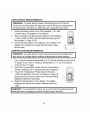
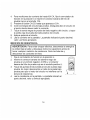
TEMPERATURE MEASUREMENTS
I ARNING: To avoid electric shock, disconnect both test probes from
any source of voltage before making a temperature measurement.
1. If you wish to measure temperature in °F, set the function switch to the
°F range. If you wish to measure temperature in °C, set the function
switch to the °C range.
2. Insert the Temperature Probe into the Temperature
Socket, making sure to observe the correct polarity.
3. Touch the Temperature Probe head to the part
whose temperature you wish to measure. Keep the
probe touching the part under test until the reading
stabilizes (about 30 seconds).
4. Read the temperature in the display. The digital
reading will indicate the proper decimal point and
value.
IWARNING: To avoid electric be the has been
shock, sure
thermocouple
removed before changing to another measurement function.
I
I
I
16

I WARNING: To avoid electric shock, disconnect the test leads from any I
source of voltage before removing the back cover or the battery or fuse
Idoors.
I WARNING: To avoid electric shock, do not operate your meter until the
I
battery and fuse doors are in place and fastened securely, u
This MultiMeter is designed to provide years of dependable service, if the
following care instructions are performed:
1. KEEP THE METER DRY. If it gets wet, wipe it off.
2. USE AND STORE THE METER IN NORMAL TEMPERATURES.
Temperature extremes can shorten the life of the electronic parts and
distort or melt plastic parts.
3. HANDLE THE METER GENTLY AND CAREFULLY, Dropping it can
damage the electronic parts or the case.
4. KEEP THE METER CLEAN, Wipe the case occasionally with a damp
cloth. DO NOT use chemicals, cleaning solvents, or detergents.
5. USE ONLY FRESH BATTERIES OF THE RECOMMENDED SIZE
AND TYPE. Remove old or weak batteries so they do not leak and
damage the unit.
6. IF THE METER IS TO BE STORED FOR A LONG PERIOD OF TIME,
the batteries should be removed to prevent damage to the unit.
REPLACING THE BATTERIES
I WARNING: To avoid electric shock, disconnect the test leads from any I
source of voltage before removing the battery door.
I
1. When the batteries become exhausted or drop below the operating
voltage, "BAT" will appear in the right-hand side of the LCD display.
The batteries should be replaced.
2. Follow instructions for installing batteries. See the Battery Installation
section of this manual.
3. Dispose of the old batteries properly.
17

IWARNING:Toavoidelectricshock,donotoperateyourmeteruntilthe
batterydoorisinplaceandfastenedsecurely.
REPLACINGTHEFUSES
WARNING:Toavoidelectricshock,disconnectthetestleadsfromany|
source of voltage before removing the fuse door.
I
1. Disconnect the test leads from the meter and any item under test.
2. Open the fuse door by loosening the screw on the door using a Phillips
head screwdriver.
3. Remove the old fuse from its holder by gently pulling it out.
4. Install the new fuse into the holder.
5. Always use a fuse of the proper size and value (0.5A/250V fast blow
for the 400mA range, 10A/250V fast blow for the 10A range).
6. Put the fuse door back in place. Insert the screw and tighten it securely.
l WARNlNG: To avoid electric shock, do not operate your meter unti. the]
fuse door is in place and fastened securely.
UL LISTED
The UL mark does not indicate that this product has been evaluated for the
accuracy of its readings.
18

/ ;(ellJ :] II :[_ -"[ele]l i I_[€
There may be times when your meter does not operate properly. Here are
some common problems that you may have and some easy solutions to
them.
Meter Does Not Operate:
1.Always read all the instructions in this manual before use.
2. Check to be sure the batteries are properly installed.
3. Check to be sure the batteries are good.
4. If the battery is good and the meter still does not operate, check to be
sure that both ends of the fuse are properly installed.
If You Do Not Understand How the Meter Works:
1. Purchase the instructional book "Multitesters and Their Use for Electrical
Testing" (Item No. 82303) at your local Sears store.
2. Call our Customer Service Line 1-888-326-1006.
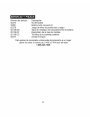
d :1_kvJ[e,]:IF.*I_Im]_.,I _JIt
Item Number
82374
93891
82378
82139-DB
82139-DF
82139-CS
82377
Description
Fuse kit
AAA battery (2 required)
Set of black and red Test Leads
Replacement battery door
Replacement fuse door
Rear cover screws
Thermocouple probe
For replacement parts shipped directly to your home
Call Monday through Friday, 9 AM - 5 PM Eastern Time
1-888-326-1006
19

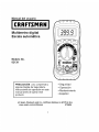
Manual del usuario
Multimetro digital
Escala autom_tica
Modelo No.
82139
3QQ Q 11
PRECAUCION: Lea, comprenda y
siga las Reglas de Seguridad e
Instrucciones de operaci6n en este
manual antes de operar este
producto
• Seguridad
• Operaci6n
• Mantenimiento
• Espa_oI
(c) Sears, Roebuck and Co., Hoffman Estates, IL 60179 U.S.A.
www.sears.com/craftsman 070606

f__:!ur__!J]:l[o,Zo]_i II:1_IIJIe
Garantia
Instrucciones de seguridad
Sefiales de seguridad
Control y conexiones
Sefiales y anunciadores
Especificaciones
Instalaci6n de la bateria
Instrucciones de operaci6n
Escala automatica/Escala manual
Retenci6n de datos
Relativo
Medici6n de voltaje CD
Medici6n de voltaje CA
Medici6n de corriente CD
Medici6n de corriente CA
Medici6n de resistencia
Prueba de continuidad
Prueba de diodo
Medici6n de frecuencia
Medici6n de capacitancia
Medici6n de temperatura
Mantenimiento
Reemplazo de baterias
Reemplazo de fusibles
Soluci6n de problemas
Servicio y piezas
Pagina
3
3
4
5
5
8
9
10
10
11
11
11
12
12
13
14
15
15
16
16
17
18
19
19
20
21

uJ_ir±q_[o] e]:l(_±q _,_±q_II_±1 I[O]lir±WI
Si este producto falla debido a un defecto en material o mano de obra
dentro de un a_o a partir de la fecha de compra, Sears Io reemplazara
libre de cargo. Regrese el producto al cualquizer tienda de Sears o
cualquier tienda de Craftsman para su reemplazo. Si este producto es
usado comercialmente o para renta, esta garantia se aplica s61o durante
los primeros 90 dias despues de la fecha de compra. Esta garantia le
derechos legales especificos; usted puede tener otros derechos que
pueden variar de estado a estado.
Sears, Roebuck and Co., Dept. 817WA, Hoffman Estates, IL 60179
Para Ayuda a Clientes Ilame al 1-888-326-1006entre 9am-5 PM (EST)
de lunes a viernes
I ADVERTENCIA: EXTREME SUS PRECAUCIONES AL USAR ESTE I
DISPOSITIVO. El uso inapropiado de este dispositivo puede resultar en
lesiones o muerte. Siga todas las salvaguardas sugeridas en estel
manual. Ademas de las precauciones de seguridad normales usadas al I
trabajar con circuitos electricos. NO repare este dispositivo, si usted no
esta calificado para hacerlo.
k _ ok mm _ mmmAmm
Este medidor ha sido diseSado para ser seguro en uso, pero el operador
debe ser cauteloso en su operaci6n. Para una operaci6n segura, debera
seguir cuidadosamente las siguientes reglas.
Limites de alimentaci6n
Funci6n
V CD o V CA
mA CD/CA
A CD/CA
Frecuencia, Resistencia, Capacitancia,
Regimen de trabajo, Prueba de diodo,
Continuidad
Temperatura
Alimentaci6n max
600V CD, 600V CA
400mA CD/CA
10A CD/CA (30 segundos
max cada 15 minutos)
250V CD/CA
60V CD/24V CA

1. NUNCAapliquealmedidor voltaje o corriente que exceda los
m&ximos especificados:
2. EXTREME SUS PRECAUClONES al trabajar con alto voltaje.
3. NO mida voltaje si el voltaje en el enchufe de entrada <<COM>>excede
500V sobre tierra fisica.
4. NUNCA conecte los alambres del medidor a una fuente de voltaje
cuando el conmutador de funci6n este en modo de corriente,
resistencia o diodo. Hacerlo puede daSar al medidor.
5. SlEMPRE descargue los capacitores de filtro en las fuentes de
energia y desconecte la energia al realizar pruebas de resistencia o
de diodo.
6. SlEMPRE corte la energia y desconecte los alambres de prueba
antes de abrir la tapa y reemplazar el fusible o baterias.
7. NUNCA opere el medidor salvo que la cubierta posterior y la tapa de
baterias y fusibles esten en su lugar y aseguradas.
,']:1_p'._1NIl:_,,']Nm]:E_,']:[€-llJ_11m7._In
±
LAOVE"TE"O'AI
[P.EcAuc,o.!
F 00V
MAX
!
Esta seSal adyacente a otra seSal, terminal o dispositivo
de operaci6n indica que el operador se debe referir a una
explicaci6n en las instrucciones de operaci6n para evitar
lesiones personales o daSos al medidor.
La sepal ADVERTENClA indica una situaci6n
potencialmente peligrosa, si no se evita, podria resultar en
lesiones graves o muerte.
Esta seSal de PRECAUClON indica una situaci6n
potencialmente peligrosa, que si no se evita, podria
resultar en lesiones, o daSos al producto.
Esta seSal advierte al usuario que las terminales asi
marcadas no deben ser conectadas en un punto del
circuito donde el voltaje, con respecto a tierra fisica,
exceda (en este caso) 500 VCA o VCD.
Esta seSal adyacente a una o mas terminales las
identifica como asociadas con escalas que pueden, bajo
uso normal, estar bajo voltajes particularmente peligrosos.
Para maxima seguridad, el metro y sus hilos de prueba no
deberan ser manejados cuando las terminales estan
energizadas.

u_o]_i / _To]I ::F.'l'ioTo] _I _14[o]_I::F:
1. Pantalla de cristal liquido de 4000
cuentas con seSales simb61icas
2. Conmutador de funci6n
3. Enchufe positivo de alimentaci6n.
4. Enchufe (negativo) de alimentaci6n
COM
5. Enchufe de alimentaci6n de 10A
(positivo) para mediciones de 10A
CD o CA
6. Selector de Continuidad/Diodo o
CA/CD
7. Bot6n pulsador de escala
8. Bot6n pulsador de retenci6n de
datos
9. Bot6n pulsador de relativo
10. Enchufe para temperatura
7
6
_8
_9
_2
--3
_4
.1:1_P':IIII:F.'i'm:l#LIJ#[o]r:l m[o][t :_
-))) Continuidad
BAT Bateria baja
-_ Diodo
HOLD Retenci6n de datos
AUTO Escala automatica
CA Voltaje o corriente alterna
CD Voltaje o corriente directa

_",)",,,1=[_]I_1[_I':T_][e)_I =[,,,",)
Funci6n
Voltaje CD
(V CD)
Voltaje CA
(V CA)
(40 - 400Hz)
Corriente
CD
(A CD)
Corriente
CA
(A CA)
(40 - 400Hz)
Resistencia
Escala
400mV
4V
40V
400V
600V
400mV
4V
40V
400V
600V
400HA
4000HA
40mA
400mA
10A
400,uA
4000HA
40mA
400mA
10A
400_.)
4k_.)
40k£_.)
400k£-._
4M_.)
40M_.)
Resoluci6n
0.1mV
lmV
10mV
100mV
1V
0.1mV
lmV
10mV
100mV
1V
0.1HA
1HA
10HA
100HA
10mA
0.1HA
1HA
10HA
100HA
10mA
0.1£-._
1£-._
10£-._
100£-,_
lk£-._
10k£-,_
Precisi6n
±(0.5%lectura + 2 digitos)
±(1.0%lectura + 2 digitos)
±(1.5%lectura + 2 digitos)
±(2.0% lectura + 30 digitos)
±(1.5%lectura + 3 digitos
±(2.0%lectura + 4 digitos
±(1.5%lectura + 3 digitos)
(10Aamas de 15 segundos)
±(2.5%lectura + 5 digitos)
±(1.8%lectura + 5 digitos)
(10Aamas de 15 segundos)
±(3.0%lectura + 7 digitos)
±(1.2%lectura + 4 digitos)
±(1.2%lectura + 2 digitos)
±(2.0%lectura + 3 digitos)

_",)",,,1=[_]I_1[_I':__][e)_I =[_
FunciSn Escala
Capacitancia 4nF
40nF
400nF
4!iF
40HF
200!iF
R@gimen de 0.1-99.9%
trabajo
Frecuencia 9.999Hz
99.99Hz
999.9Hz
9.999kHz
99.99kHz
999.9kHz
9.999MHz
Temp. °F -4 a 1400°F
Temp. °C -20 a 760°C
Resoluci6n
lpF
10pF
0.1nF
lnF
10nF
0.1!iF
0.1%
0.001Hz
0.01Hz
0.1Hz
1Hz
10Hz
100Hz
lkHz
1OF
1oc
Precisi6n
±(5.0%lectura + 10 digitos)
±(5.0%lectura + 7 digitos)
±(3.5%lectura + 5 digitos)
±(5.0%lectura + 5 digitos)
±(1.2%lectura + 2 digitos)
Ancho de impulso: 100!_s - 100ms
±(1.5%lectura + 5 digitos)
±(1.2%lectura + 5 digitos)
±(1.5%lectura + 4 digitos)
±(3.0%lectura + 3 digitos)
NOTA: Las especificaciones de precisl6n consisten de dos elementos:
• (% lectura) - Esta es la precisiSn del circuito de mediciSn.
• (+ digitos) - Esta es la precisiSn del convertidor analogo a digital.
NOTA: La precisi6n es indicada de 18°C a 28°C (65°F a 83°F) y menos de
70% RH.
Prueba de diodo Corriente de prueba de 0.3mA maximo, voltaje
de circuito abierto 1.5V CD tipico
Prueba de continuidad Sonara una seSal audible si la resistencia es
menor a aproximadamente 30£-._,corriente de
prueba <0.7mA
Temperatura sensor Requiere termopar tipo K

Tasa de medici6n
Apagado autom&tico
Indicaci6n de bateria baja
Baterias
Fusibles
Impedancia de alimentaci6n 7.5M_-._(VCD y VCA)
Pantalla 4000 cuentas LCD
Indicaci6n de fuera de escala <<OL>>indicado
Polaridad Automatico (no hay indicaci6n para polaridad
positiva); Signo de menos (-) para polaridad
negativa.
2 veces por segundo, nominal
El medidor se apaga automaticamente
despues de 15 minutos de inactividad
Se indica _BAT>>si el voltaje de la bateria es
menor al voltaje de operaci6n
Requiere dos baterias AAA (vendido por
separado)
Escalas mA, ,_A, 0.5A/250V quemado rapido
Escala 10A, 10A/250V quemado rapido
Temperatura de operaci6n 0°C a 50°C (32°F a 122°F)
Temperatura de almacenamiento --20°C a 60°C (4°F a 140°F)
Humedad relativa <70% operaci6n, <80% almacenamiento
Altitud de operaci6n 2000 metros (7000ft.) maximo.
Peso 260g (9.17 oz.).
Dimensiones 121.5mm x 60.6mm x40mm (4.78" x 2.38" x
1.57")
Seguridad Para uso en interiores, de conformidad con la
Categoria II de sobretensi6n, grado de
contaminaci6n 2. La Categoria II incluye nivel
local, electrodomesticos, equipo portatil, etc.,
con sobretensiones transitorias menores a la
Categoria III de sobretensi6n.

I I_[_'-]1ir_*1IF_*T_][e] _II e):ll Ir_*ll:]r-*11/ :1;,,1r:l
i I
de prueba de cualquier fuente de voltaje antes de abrir la tapa de la
bateria.
1. Desconecte los hilos de prueba del medidor.
2. Quite la funda de goma (siesta colocada).
3. Abra la tapa de la bateria aflojando el tornillo con un
destomillador de cabeza Phillips.
4. Inserte las baterias en el porta baterias, observando
que la polaridad sea correcta.
5. Vuelva a colocar la tapa de la bateria. Asegure con
los dos tomillos.
I ADVERTENClA: Para evitar choque electrico, no haga funcionar el
medidor hasta que la tapa de la bateria este asegurada.
NOTA: Si su medidor no funciona correctamente, revise los fusibles y las
baterias para asegurar que aQn estan en buenas condiciones y que estan
instaladas apropiadamente.

_. _ O_. II O" __A O_.
I ADVERTENClA: de electrocuci6n. Los circuitos de alto
Riesgo voltaje,
tanto CD y CA, son muy peligrosos y deberan ser medidos con gran
cuidado.
1. SIEMPRE gire el conmutador de funci6n a la posici6n OFF cuando el
medidor no este en uso. Este medidor tiene Auto OFF, que
automaticamente apaga el medidor si transcurren mas de 15 minutos
entre usos.
2. Si en la pantalla aparece <<OL>>durante una medici6n, el valor excede
la escala seleccionada. Cambie a una escala mas alta.
NOTA: En algunas escalas bajas de voltaje CA y voltaje CD, la pantalla
puede mostrar una lectura fluctuante sin estar conectados los alambres de
prueba a dispositivo alguno,. Esto es normal yes causado por la alta
sensibilidad de alimentaci6n. La lectura se estabilizara y rendira la medida
correcta al estar conectado a un circuito.
SELECCION de ESCALA AUTOMATICAl ESCALA MANUAL
AI encender por primera vez el medidor, este entra automaticamente en
escala automatica. Este selecciona automaticamente la mejor escala para
las mediciones que se van a realizar y generalmente es el mejor modo
para la mayoria de las mediciones. Para situaciones de medici6n que
requieren la selecci6n manual de la escala, Ileve a cabo los siguientes
pasos:
1. Presione el bot6n RANGE. Se apagara el indicador de pantalla
<<AUTO>>.
2. Presione el bot6n RANGE para pasar por pasos a traves de las
diferentes escalas disponibles hasta seleccionar la escala deseada.
3. Presione y sostenga el bot6n RANGE durante 2 segundos para salir
del modo escala manual y regresar a escala automatica.
I
10

RETENCION DE DATOS
La funci6n de retenci6n de datos permite al medidor <_congelar_ una
medida para referencia posterior.
1. Presione el bot6n DATA HOLD para <_congelar_ la lectura en el
indicador. En la pantalla aparecera el indicador <_HOLD_.
2. Presione el bot6n DATA HOLD para regresar a operaci6n normal.
RELATIVO
La funci6n RELATIVO le permite tomar medidas relativas a un valor de
referencia almacenado. Se puede almacenar un voltaje, corriente, etc., de
referencia y se pueden tomar medidas comparadas con ese valor. El valor
mostrado es la diferencia entre el valor de referencia y el valor medidor.
1. Tome cualquier medida como se describe en las instrucciones de
operaci6n.
2. Presione el bot6n RELATIVE para almacenar la lectura de la pantalla y
aparecera el indicador _REL_.
3. La pantalla indicara ahora la diferencia entre el valor almacenado y el
valor medido.
4. Presione el bot6n RELATIVE para regresar a operaci6n normal.
MEDIClON DE VOLTAJE CD
PRECAUClON: No mida voltaje CD si en el circuito se esta
encendiendo y apagando un motor. Pueden ocurrir grandes sobre
cargas de voltaje durante las operaciones de encendido y apagado
que pueden daSar al medidor.
1. Fije el conmutador de funci6n en la posici6n V DC
(en la pantalla aparecera <<mV>>).
2. Inserte el conector banana del alambre negro de
prueba en el enchufe negativo (COM) y el conector
banana del hilo de prueba rojo en el enchufe
positivo (V).
3. Toque las puntas de las sondas al circuito bajo
prueba. Cerci6rese de observar la polaridad
correcta (rojo a positivo, negro a negativo).
4. Lea el voltaje en la pantalla. La pantalla indicara el
11

puntodecimalyvalorapropiado.Siseinviertelapolaridad,lapantalla
indicara(-)menosantesdelvalor.
MEDIClONDEVOLTAJECA
ADVERTENClA:Riesgodeelectrocuci6n.Laspuntasdelassondas
puedennoserIosuficientementelargasparahacercontactocon
partesvivasdentrodealgunostomasdecorrientede240Vpara
aparatosdebidoaqueloscontactosestanembutidosprofundamente
enlacajadetoma.Comoresultado,lalecturapuedeindicar0voltios
cuandoenrealidadelcontactositienevoltaje.Cerci6resequelas
puntasdelassondasestantocandoloscontactosdemetaldentrode
latomaantesdeasumirquenohayvoltajepresente.
PRECAUClON:NomidavoltajeCA,sienelcircuitoseesta
encendiendoyapagandounmotor.Puedenocurrirgrandessobre
cargasdevoltajedurantelasoperacionesdeencendidoyapagado
quepuedendafiaralmedidor.
Fijeelconmutadordefunci6nenlaposici6nVAC.
21Inserteelconectorbananadelalambrenegrodeprueba
enelenchufenegativo(COM)yelconectorbananadel
hilodepruebarojoenelenchufepositivo(V).
3. Toquelaspuntasdelassondasalcircuitobajoprueba.
4. Leaelvoltajeenlapantalla.Lapantallaindicaraelpunto
decimal,valorysimboloapropiado(CA,V,etc.).
MEDIClONDECORRIENTECD
PRECAUClON:nohagamedicionesdecorrienteenlaescalade10A
durantemasde30segundos.Silamedici6nseextiendeamasde30
segundoselmultimetroy/olosconductoresdepruebapodriansufrir
dafios.
1. Inserteelconectorbananadelalambrenegrodepruebaenelenchufe
negativo(COM).
2. Paramedicionesdecorrientedehasta4000,uACD,fijeelconmutador
defunci6nenlaposici6n,uAeinserteelconectorbananadelhilode
pruebarojoenelenchufe(,uA).
12

3. Paramedicionesdecorrientedehasta400mACD,fijeelconmutador
defunci6nenlaposici6ndelaescalamAeinserteel
conectorbananarojoenelenchufe(mA).
4. Paramedicionesdecorrientedehastal0ACD,fijeel
conmutadordefunci6nenlaposici6nAeinserteel
conectorbananadelhilodepruebarojoenelenchufe
10A.
5. Presioneelbot6nCA/CDhastaqueaparezca<<CD>>.
6. Cortelaenergiadelcircuitobajoprueba,enseguidaabra
elcircuitoenelpuntodondedeseamedirlacorriente.
7. Toquelasondanegradepruebadelladonegativodelcircuito.Toque
lasondarojadepruebadelladopositivodelcircuito.
8. Apliquepotenciaalcircuito.
9. Lealacorrienteenlapantalla.Lapantallaindicaraelpuntodecimal,
valorysimboloapropiado.
MEDICION DE CORRIENTE CA
I DVERTENCIA: Para evitar choque electrico, no mida corriente CA en
circuito alguno cuyo voltaje exceda 250V CA.
I RECAUCION: no haga mediciones de corriente en la escala de 10 A
durante mas de 15 segundos. Si la medici6n se extiende a mas de 15
segundos el multimetro y/o los conductores de prueba podrian sufrir
dafios.
1. Inserte el conector banana del alambre negro de prueba
en el enchufe negativo (COM).
2. Para mediciones de corriente de hasta 400%A CA, fije el
conmutador de funci6n en la posici6n ,A e inserte el
conector banana del hilo de prueba rojo en el enchufe
(,A).
3. Para mediciones de corriente de hasta400mA OA, fije el
conmutador de funci6n en la posici6n de la escala mA e
inserte el conector banana rojo en el enchufe (mA).
13

4. Paramedicionesdecorrientedehastal0ACA,fijeelconmutadorde
funci6nenlaposici6nAeinserteelconectorbananadelhilode
pruebarojoenelenchufe10A.
5. Presioneelbot6nCA/CDhastaqueaparezca<<CA>>.
6. Cortelaenergiadelcircuitobajoprueba,enseguidaabraelcircuitoen
elpuntodondedeseamedirlacorriente.
7. Toquelasondanegradepruebadelladonegativodelcircuito,ytoque
lasondarojadepruebadelladopositivodelcircuito.
8. Apliquepotenciaalcircuito.
9. Lealacorrienteenlapantalla.Lapantallaindicaraelpuntodecimal,
valorysimboloapropiado.
MEDICION DE RESISTENCIA
ADVERTENCIA: Para evitar choque electrico, desconecte la energia a
la unidad bajo prueba y descargue todos los capacitores antes de
tomar cualquier medici6n de resistencia. Quite las baterias y
desconecte los cordones de linea.
Fije el conmutador de funci6n en la posici6n £-2.
2. Inserte el conector banana del alambre negro de
prueba en el enchufe negativo (COM) y el conector
banana del hilo de prueba rojo en el enchufe positivo £-2.
3. Toque las puntas de las sondas al circuito o pieza bajo
prueba. Es mejor desconectar un lado de la pieza bajo
prueba para que el resto del circuito no interfiera con la
lectura de resistencia.
4. Lea la resistencia en la pantalla. La pantalla indicara el
punto decimal, valor y simbolo apropiado.
14

PRUEBA DE CONTINUIDAD
I ADVERTENCIA: Para evitar choque electrico, nunca mida continuidad I
en circuitos o alambres que tengan voltaje en ellos.
1. Fije el conmutador de funci6n en la posici6n -_o))).
2. Inserte el conector banana negro en el enchufe
negativo (-) (COM) y el conector banana del hilo de
prueba rojo en el enchufe positivo (+) (£-._).
Presione el bot6n-_o)))hasta que en la pantalla
aparezca
Toque las puntas de las sondas al circuito o alambre
que desea revisar.
Si la resistencia es menor a aproximadamente 30
ohms, sonata la seSal audible. La pantalla tambien
indicara la resistencia real.
3.
4.
5.
PRUEBA DE DIODO
I DVERTENCIA: Para evitar choque electrico, no prueba cualquier
diodo que tenga voltaje.
1. Fije el conmutador de funci6n a la posici6n -_°)))
2. Presione el bot6n-_ °)))hasta queen la pantalla aparezca-_,)))
3. Inserte el conector banana negro en el enchufe negativo (-) (COM) y el
conector banana del hilo de prueba rojo en el enchufe positivo (+) (£-._).
4. Toque las puntas de las sondas al diodo o uni6n de semiconductor que
desea probar. Note la lectura del medidor.
5. Invierta la polaridad de las sondas cambiando su posici6n. Note esta
6.
lectura.
El diodo o uni6n pueden ser evaluados de la siguiente
manera:
A. Si una lectura muestra un valor y la otra lectura
muestra OL, el diodo esta bueno.
B. Si ambas lecturas muestran OL, el dispositivo esta
abierto.
C. Si ambas lecturas son muy pequeSas o 0, el
dispositivo tiene corto.
15

NOTA:Elvalorindicadoenlapantalladurantelapruebadediodoesel
voltajedirecto.
MEDIClON DE FRECUENClA O FACTOR DE TRABAJO
1. Fije el conmutador de funci6n en la posici6n FREQ.
2. Inserte el conector banana negro en el enchufe
negativo (-) (COM) y el conector banana del hilo
de prueba rojo en el enchufe positivo (+) (F).
3. Presione la tecla Hz/% para seleccionar {{Hz)) or
{( O/o )).
4. Toque las puntas de las sondas al circuito bajo
prueba.
5. Lea la frecuencia en la pantalla. La lectura digital
indicara el punto decimal, simbolos (Hz, kHz) y
valor apropiados.
MEDICION DE CAPACITANCIA
ADVERTENCIA: Para evitar choque electrico, desconecte la energia a
la unidad bajo prueba y descargue todos los capacitores antes de
tomar cualquier Medici6n de capacitancia. Quite las baterias y
desconecte los cordones de linea.
2.
3.
Fije el conmutador de funci6n en la posici6n CAP,
(en la pantalla aparecer_l <<nF>>y un valor pequefio).
Inserte el conector banana negro en el enchufe
negativo (-) (COM) y el conector banana del hilo de
prueba rojo en el enchufe positivo (+) (CAP).
Toque los hilos de prueba al capacitor que se va a
probar. La pantalla indicara el punto decimal, valor y
simbolo apropiado.
16

MEDICIONES DE TEMPERATURA
I ADVERTENCIA: Para evitar choque electrico, desconecte ambas
sondas de prueba de cualesquier fuente de voltaje antes de tomar
mediciones de temperatura.
1. Si desea tomar mediciones de temperatura en °F,
fije el conmutador de funciSn en la escala °F. Si
desea tomar mediciones de temperatura en °C, fije
el conmutador de funciSn en la escala °C.
2. Inserte la sonda de temperatura en el enchufe para
temperatura, asegurando que observa la polaridad
correcta.
3. Toque la cabeza de la sonda de temperatura a la
pieza cuya temperatura desea medir. Mantenga la sonda tocando la
pieza bajo prueba hasta que la lectura se estabilice (Aproximadamente
30 segundos).
4. Lea la temperatura en la pantalla. La lectura digital indicara el punto
decimal y valor apropiado.
IADVERTENClA: Para evitar electrico, cerciSrese el
I
choque que termopar
ha sido desconectado antes de cambiar la funciSn de mediciSn.
I
17

ADVERTENClA: Para evitar choque electrico, desconecte los alambres I
de prueba de cualquier fuente de voltaje antes de quitar la cubierta
Iposterior o la tapa de la bateria o fusible.
ADVERTENClA: Para evitar choque electrico, no opere su medidor I
hasta que las tapas de la bateria y fusibles esten aseguradas en su
I
lugar.
Este multimetro esta diseSado para proporcionar muchos aSos de servicio
confiable si se Ilevan a cabo las siguientes instrucciones de cuidado:
1. MANTENGA EL MEDIDOR SECO. Si se moja, sequelo.
2. USE Y ALMACENE EL MEDIDOR EN TEMPERATURAS
NORMALES. Los extremos de temperatura pueden acortar la vida de
las piezas electr6nicas y deformar o derretir las piezas de plastico.
3. MANEJE EL MEDIDOR CON SUAVlDAD Y CUlDADO. Dejarlo caer
puede daSar las piezas electr6nicas o la caja.
4. MANTENGA EL MEDIDOR LIMPIO. Peri6dicamente limpie el medidor
con un paso ht3medo. NO use quimicos, solventes para limpieza o
detergentes.
5. USE SOLO BATERiAS CARGADAS DEL TIPO Y DIMENSlONES
RECOMENDADAS. Retire las baterias viejas o debiles para que no se
derramen y daSen a la unidad.
6. Sl EL MEDIDOR VA A SER ALMACENADO DURANTE UN LARGO
PERIODO DE TIEMPO, debera retirar las baterias para prevenir daSos
a la unidad.
18

REEMPLAZO DE LAS BATERiAS
i araev, aroho uee,eotr,oo,desooneote,osa,am resI
de prueba de cualquier fuente de voltaje antes de abrir la tapa de la
bateria.
1. Cuando se consuma la carga de las baterias o caiga debajo del voltaje
de operaci6n, en la pantalla LCD aparecer_l el indicador <<BAT>>del
lado derecho. Debera reemplazar las baterias.
2. Siga las instrucciones para instalar las baterias. Vea la secci6n:
Instalaci6n de la bateria, en este manual
3. Deseche la bateria usada de manera apropiada.
I ADVERTENCIA: Para evitar electrico, no su medidor
I
choque opere
hasta que la tapa de la bateria este asegurada en su lugar. !
REEMPLAZO DE LOS FUSIBLES
I ADVERTENClA: Para evitar cheque electrico, desconecte las sondas I
de prueba de cualquier fuente de voltaje antes de abrir la tapa de los
fusibles.
1. Desconecte los hilos de prueba del medidor y cualquier articulo bajo
prueba.
2. Abra la tapa de fusibles aflojando el tornillo de la tapa con un
destomillador de cabeza Phillips.
3. Retire el fusible quemado de su soporte tirando suavemente hacia
afuera.
4. Instale el fusible nuevo en el soporte.
5. Siempre use un fusible del tamaSo y valor apropiado(0.5A/250V
quemado rapido para la escala de 400mA, 10A/250V quemado rapido
para la escala de 10A).
6. Vuelva a colocar la tapa en su lugar. Inserte el tomillo y apriete.
I ADVERTENClA: Pars evitar choque electrico, no opera su medidor I
hasta que la tapa de fusibles este asegurada.
19

INSCRITO EN UL
La marca UL no indica que la precisiSn de las lecturas de este producto
han sido evaluadas.
•_o]mLu[o][o]_IIm]:11:,K{o]:]ml:l,v_r.*T_
Puede haber ocasiones en que su medidor no funcione correctamente.
Estos son algunos problemas comunes que puede tener y algunas
soluciones faciles para ellos.
El medidor no funciona:
1. Lea siempre todas las instrucciones en este manual antes de cada uso.
2. Revise que la bateria esta instalada correctamente.
3. Revise que la bateria este en buen estado.
4. Si la bateria esta en buen estado y el medidor ann no funciona, revise
que los dos extremos del fusible esten insertados correctamente.
Si no comprende como funciona el medidor:
1. Compre el instructivo <<Multitesters and Their Use for Electrical
Testing>> (Item No. 82303) en la tienda Sears de su Iocalidad.
2. Llame a nuestra linea de Servicio a Clientes al te1.1-888-326-1006.
20

NQmerodearticulo
82374
93891
82378
82139-DB
82139-DF
82139-CS
82377
Descripci6n
Kitdelfusible
BateriaAAA(requiere2)
Juegodehilosdepruebarojoynegro
Tapaderemplazodelcompartimentodebateria
Reemplazodelatapadefusibles
Tornillosdelacubiertaposterior
Sondatermopar
Parapiezasdereemplazoembarcadasdirectamenteasuhogar
Llamedelunesaviemesde,9AMa5PMhoradeleste
1-888-326-1006
21
-
 1
1
-
 2
2
-
 3
3
-
 4
4
-
 5
5
-
 6
6
-
 7
7
-
 8
8
-
 9
9
-
 10
10
-
 11
11
-
 12
12
-
 13
13
-
 14
14
-
 15
15
-
 16
16
-
 17
17
-
 18
18
-
 19
19
-
 20
20
-
 21
21
-
 22
22
-
 23
23
-
 24
24
-
 25
25
-
 26
26
-
 27
27
-
 28
28
-
 29
29
-
 30
30
-
 31
31
-
 32
32
-
 33
33
-
 34
34
-
 35
35
-
 36
36
-
 37
37
-
 38
38
-
 39
39
-
 40
40


Craftsman 82139 El manual del propietario
- Categoría
- Multimetros
- Tipo
- El manual del propietario
En otros idiomas
- English: Craftsman 82139 Owner's manual
Documentos relacionados
Otros documentos
-
Velleman DVM9912 Manual de usuario
-
Wavetek 2015 Manual de usuario
-
-
Beta 1760/RMS Instrucciones de operación
-
-
 Wavetek Meterman HD115B Manual de usuario
-
-
Klein Tools MM200 Manual de usuario
-
 Commercial Electric MS602H Instrucciones de operación
-
Panasonic SEC-HR3U8BPN Ficha de datos

