
USE AND CARE GUIDE
COMMERCIAL ELECTRIC PREMIUM
LED RECESSED GIMBAL KIT
Safety Information
Questions, problems, missing parts? Before returning to the store,
call Commercial Electric Customer Service
8 a.m.- 7 p.m., EST, Monday-Friday, 9 a.m. - 6 p.m., EST, Saturday
1-877-527-0313
HOMEDEPOT.COM
Warranty
Pre-Installation
PLANNING INSTALLATION
Compare all parts with the Package Contents list in this manual. If any part is missing or
damaged, do not install this product. Contact the Customer Service Team.
Installation
Model #
2003031702 WH
2003031602 DB
2003031802 BN
Fig. 1
Ceiling joist
Ceiling
Fig. 3.2
Top cover
NM Cable
or
BX Cable
NM Cable
strain relief
Junction
Box
Wire Terminal
Fig. 3.3
Wire Terminal
NM Cable
or
BX Cable
Junction
Box
Removable
strain relief
Top cover
NM Cable
Fig. 5
NM Cable
or
BX cable
Lower
springs
Upper
springs
Upper springs
Ceiling
Fig. 6
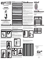
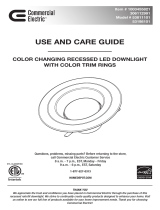
1.Choose the location for the fixture, taking into consideration the 5 in. depth clearance
requirement, the location of ceiling joists and the accessibility for the electrical supply.
Mark the selected location with a circle using the provided 3-1/4 in. diameter template.
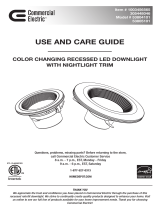
2. Use a keyhole saw to cut a 3-1/4 in. diameter hole in the ceiling surface (Fig. 1).
3. Run non-metallic (NM) cable (also known as Romex) or an armored cable (also
known as BX) from your source power to the first hole, providing 6 in. (15.2 cm) to 8 in.
(20.3 cm) of slack extending below the hole (Fig. 2). Cable up to 12 AWG may be used .
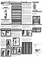
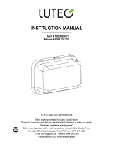
4. Slightly loosen both Phillips head screws
on the junction box top cover. Slide the top
cover to the side, then rotate to open the
junction box (Fig. 3.1). Insert 5-6 in. of NM
cable into the junction box through one of the
strain relief slots (Fig. 3.2). If you are using a
BX cable, remove the black plastic NM cable
strain relief in order to secure the BX cable to
the junction box. If daisy-chaining to another
downlight, insert the next section of NM cable
or BX cable into the other strain-relief slot
(Fig. 3.3).
5. Remove at least 3 in. of the cable’s outer sheath and remove the plastic or paper
over-wrap. Strip approximately 3/8 in. of insulation from the ends of all supply wires.
Using the wire connectors, make the following wire connections within the junction box
(Fig. 3.2 and 3.3):
WHITE Fixture Wire to WHITE (NEUTRAL) Supply Wire
BLACK Fixture Wire to BLACK (HOT) Supply Wire
6. Carefully push the wires and the wire connections into the junction box. Close the
junction box cover. Tighten the fastening screws.
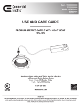
7. Adjust light color settings to the desired levels (Fig. 4).
Light Color Settings:
The light color settings adjust the color temperature (K) of the LEDs from 2700K
(warm white) all the way to 5000K (daylight). Application type and personal preference
usually dictate the color temperature needed. Most residential applications utilize
2700K or 3000K- more of a yellowish hue. Commercial offices and outdoor settings
typically use 4000K or 5000K- more of a bluish hue. While most consumers will
choose the factory setting of 2700K, it is mostly personal preference.
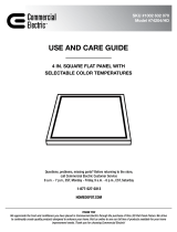
9. Flip up the spring clips against the junction box and insert the fixture into the ceiling
hole, junction box first. The longer upper springs go up through the ceiling hole. The
smaller lower springs stay below the ceiling. Place your fingers between the ceiling
and the lower springs to prevent them from marking the ceiling surface when installing
(Fig 5).
10. Continue inserting the fixture into the hole until the upper springs are engaged
above the ceiling and the fixture trim is flush against the ceiling (Fig. 6).
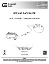
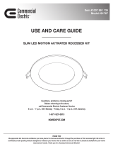
11. To adjust the direction of the light, pull out the gimbal head and twist to desired
direction (Fig. 7). The gimbal can be rotated to 40 degrees vertically and 350 degrees
horizontally. Use the indentation shown below to assist in pulling the gimbal head out
of the housing (Fig. 8).
Dimming
Dimming performance may depend on the dimmer, the dimmer range adjustment
setting (for dimmers with brightness range adjustments), the wiring method, and/or the
number of LED modules installed onto the dimmer circuit.
For dimmer selection, it is recommended to use one of the following dimmers:
Five-year Limited Warranty
Commercial Electric warrants this product to be free from defects in materials and
workmanship for five years from the original date of purchase by the consumer. This
warranty is limited to the counter replacement at the time of purchase, with the original
purchase receipt. Commercial Electric will not be liable for the loss or damage of any
kind, incidental or consequential damages of any kind, whether based on warranty
contract or negligence, and arising in connection with the sale, use or repair of the
product claimed to be defective. Some states do not allow the exclusion or limitation of
incidental or consequential damages so the above limitation may not apply to you. This
warranty gives you specific legal rights and you may also have other rights, which vary
from state to state. Misuse, accident, improper installation or maintenance will also
void the warranty.
This device complies with Part 15 of the FCC rules. Operation is subject to the
following two conditions:
(1) this device may not cause harmful interference, and
(2) this device must accept any interference received, including interference that may
cause undesired operation. This equipment, if not installed and used in accordance
with the instructions, may cause harmful interference to radio communications. Any
changes or modifications not expressly approved by the manufacturer could void the
user's authority to operate the equipment.
NOTE: This equipment has been tested and found to comply with the limits for a Class
B digital device, pursuant to Part 15 of the FCC Rules. These limits are designed to
provide reasonable protection against harmful interference in a residential installation.
This equipment generates, uses and can radiate radio frequency energy and, if not
installed and used in accordance with the instructions, may cause harmful interference
to radio communications. However, there is no guarantee that interference will not
occur in a particular installation. If this equipment does cause harmful interference to
radio or television reception, which can be determined by turning the equipment off and
on, the user is encouraged to try to correct the interference by one or more of the
following measures: reorient or relocate the receiving antenna; increase the separation
between the equipment and receiver; connect the equipment into an outlet on a circuit
different from that to which the receiver is connected; consult the dealer or an
experienced radio/TV technician for help.
For product questions or feedback, contact the Customer Service Team at
1-877-527-0313 or visit www.HomeDepot.com.
READ AND FOLLOW ALL SAFETY INSTRUCTIONS
PACKAGE CONTENTS
TOOLS REQUIRED
1. Hand saw
2. Screwdriver
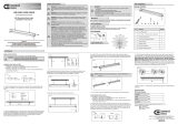
SPECIFICATIONS
3 in. Premium Gimbal Kit
THANK YOU
enhance your home. Visit us online to see our full line of products available for your home
improvement needs. Thank you for choosing Commercial Electric!
We appreciate the trust and confidence you have placed in Commercial Electric
through the purchase of this LED Gimbal Kit.
We strive to continually create quality products designed to
Fig. 7
40Deg
350Deg
Fig. 8
Fig. 2
Ceiling
NM Cable or
BX Cable
Hole
8. Raise the Premium Kit up to the ceiling hole, while simultaneously pushing the
excess NM cable or BX cable into the ceiling (Fig. 5).
Power(W) 10.5W
Finish White / Dark Bronze / Brushed Nickel
2700K/3000K/3500K/4000K/5000K
650lm
CCT(K) 5-Step Select
Lumen(lm)
Product Model
3 in. Premium Gimbal Kits
3-1/4 in.
Cut Out Diameter
FCC responsible party name: Dangoo Electronics (USA) Co., LTD
Address: 2494 Sand Hill Road
Bldg 7, Suite 100
Menlo Park, CA 94025
United States
650-422-3572
ytitnauQnoitpircseDtraP
Wire Connectors
3A
Ceiling cutout template
1C
LED Gimbal Kit
1B
WARNING – Risk of fire or electric shock. Lighting installation requires
knowledge of electrical systems. If not qualified, do not attempt installation.
Contact a qualified electrician.
WARNING – Risk of fire or electric shock. Disconnect power at fuse or circuit
breaker before installing or servicing.
WARNING – This fixture is an IC type fixture. Some insulation types that
meet this requirement are blanket batting/roll and blown-in loose fill. Do
not install in a ceiling with spray foam type insulation. Any part of the
fixture may come in direct contact with combustible material, such as a ceiling
joist or floor board.
WARNING – To prevent wiring damage or abrasion, do not expose wiring to
edges of sheet metal or other sharp objects.
WARNING – Min. temperature rating of -20°C.
WARNING – This fixture may be installed over a wet or damp location such as
a shower stall or bathtub enclosure. The area above the ceiling surface must,
however, be a dry location.
WARNING – This fixture is designed for ceiling surfaces that are 1-1/4 in. thick or
less. Do not use this fixture on ceiling surfaces that are thicker than 1-1/4 in.
WARNING – This fixture requires an existing ceiling surface, such as drywall,
for installation. To install this fixture, a hole needs to be made into the ceiling
surface at the desired location. Then, power supply wiring (NM cable) needs to
be installed from the power source to the hole.
WARNING – Do not make or alter any open holes in an enclosure of wiring or
electrical components during kit installation.
Note: Be sure not to make the hole any larger than specified. An oversized
hole may not allow for proper installation.
Note: This fixture does not require a ground wire. Secure supply ground wire
end(s) together with a wire connector.
5000K-Daylight
4000K-Bright White
3500K-Neutral White
3000K-Soft White
2700K-Warm White
Fig. 4
Light Color
Daylight
Warm
White
5000K
4000K
3500K
3000K
2700K
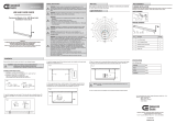
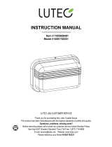
Average beam angle45.8°
Light Distribution
0
200
400
600
800
1000
180.0°
150.0°
120.0°
90.0°
60.0°
30.0°
0.0°
30.0°
60.0°
90.0°
120.0°
150.0°
0-180
90-270
Fig. 3.1
Junction box top cover
No. Brand Dimmer Family Model
1 Lutron Skylark CTCL-153PDH-WH
2 Leviton Sure Slide R62-06674-P0W
4 Eaton Sky AL SAL06P-LA-K
5 Lutron Caseta P-PKG1W-WH-R
6 Lutron Maestro MACL-153MH-WH
7 Lutron Diva DVCL-153PR-WH
8 Eaton AL Series AAL06-C1
9 Leviton Decora R12-06672-1LW
10 Leviton IllumaTech R50-1PL06-10M
11 Lutron Toggler TGCL-153PH-WH
3 Lutron Diva DVELV-303P
WARNING – Use cables having wires rated 90˚C or more.

GUÍA DE USO Y CUIDADO
KIT PRÉMIUM DE ILUMINACIÓN LED EMPOTRADA
Y CARDÁNICA DE COMMERCIAL ELECTRIC
Información de seguridad
¿Tiene preguntas o problemas, o le faltan piezas? Antes de devolver a la tienda,
llame al Servicio al Cliente de Commercial Electric
Lunes a viernes de 8:00 a.m. a 7:00 p.m., EST, y los sábados de 9:00 a.m. a 6:00 p.m., EST
1-877-527-0313
HOMEDEPOT.COM
Garantía
Antes de la instalación
PLANIFICACIÓN DE LA INSTALACIÓN
Compare todas las partes con la lista de contenido del paquete en este manual. Si falta alguna
parte o está dañada, no instale el producto. Póngase en contacto con el equipo de servicio al cliente.
Instalación
Model #
2003031702 WH
2003031602 DB
2003031802 BN
Figura 1
Vigueta de techo
Techo
Figura 3.2
Cubierta
superior
Cable NM
o BX
Alivio de
tensión de
cable NM
Caja de
conexiones
Terminal del cable
Figura 3.3
Terminal del cable
Cable NM
o BX
Caja de
conexiones
Alivio de
tensión
removible
Cubierta
superior
Cable NM
Figura 5
Cable NM
o cable BX
Resortes
inferiores
Resortes
superiores
Resortes
superiores
Techo
Figura 6
1. Elija la ubicación de la lámpara, teniendo en cuenta el requisito de espacio libre de 5 pulgadas
de profundidad, la ubicación de las vigas del techo y la accesibilidad del suministro eléctrico.
Marque la ubicación seleccionada con un círculo usando la plantilla de 3-1/4 de pulgada de
diámetro que se proporciona.
2. Use una sierra de calar para cortar un agujero de 3-1/4 de pulgada de diámetro en la superficie
del techo (Figura 1).
3. Tienda un cable no metálico (NM) (también conocido como Romex) o un cable blindado (también
conocido como BX) desde la fuente de alimentación hasta el primer agujero, proporcionando de 6 a
8 pulgadas (15.2 a 20.3 cm) de holgura para extender debajo del agujero (Figura 2). Se puede usar
un cable de calibre hasta 12 AWG.
4. Afloje ligeramente los dos tornillos de cabeza
Phillips en la cubierta superior de la caja de
conexiones. Deslice la cubierta superior hacia un
lado, luego gírela para abrir la caja de conexiones
(Figura 3.1) Inserte de 5 a 6 pulgadas de cable NM
en la caja de conexiones a través de una de las
ranuras de alivio de tensión (Figura 3.2) Si está
utilizando un cable BX, extraiga el plástico negro
de alivio de tensión para cable NM con el fin de
asegurar el cable BX a la caja de conexiones. Si se
conecta en cadena a otra lámpara, inserte la
siguiente sección de cable NM o BX en la otra
ranura de alivio de tensión (Figura 3.3)
5. Quite al menos 3 pulgadas del revestimiento externo del cable y de la envoltura interna de
plástico o papel. Pele aproximadamente 3/8 de pulgada del aislamiento del extremo de todos los
cables de suministro. Usando los conectores de cable, realice las siguientes conexiones de cable
dentro de la caja de conexiones (Figuras 3.2 y 3.3):
Cable de la lámpara BLANCO a cable de suministro BLANCO (NEUTRO)
Cable de la lámpara NEGRO a cable de suministro NEGRO (VIVO)
6. Empuje con cuidado los cables y conexiones de cables hacia dentro de la caja de conexiones.
Cierre la tapa de la caja de conexiones. Apriete los tornillos de fijación.
7. Ajuste la configuración del color de la luz a los niveles deseados (Figura 4).
Configuración del color de la luz:
La configuración de color de la luz ajusta la temperatura de color (K) de los LED desde 2700 K
(blanco cálido) hasta 5000 K (luz diurna). El tipo de aplicación y la preferencia personal
generalmente determinan la temperatura de color necesaria. La mayoría de las aplicaciones
residenciales utilizan 2700 K o 3000 K, que se parece más a un tono amarillento. Las oficinas
comerciales y los entornos al aire libre suelen usar 4000 K o 5000 K, que se parece más a un
tono azulado. Si bien la mayoría de los consumidores elegirán la configuración de fábrica de 2700
K, esto es principalmente una preferencia personal.
9. Levante los clips de resorte contra la caja de conexiones e inserte la lámpara en el agujero del
techo, pasando primero la caja de conexiones. Los resortes superiores más largos deben pasar a
través del orificio del techo. Los resortes inferiores más pequeños permanecen por debajo del
techo. Coloque los dedos entre el techo y los resorte inferiores para evitar que marquen la
superficie del techo durante la instalación (Figura 5).
10. Continúe insertando la lámpara en el agujero hasta que los resortes superiores se enganchen
por encima del techo y la moldura del dispositivo quede a ras del techo (Figura 6).
11. Para ajustar la dirección de la luz, extraiga la cabeza del cardán y gírela en la dirección
deseada (Figura 7). El cardán se puede girar a 40 grados verticalmente y 350 grados
horizontalmente. Use la muesca que se muestra a continuación para ayudar a sacar la cabeza
del cardán de la carcasa (Figura 8).
Atenuación
El funcionamiento de la atenuación puede depender del atenuador, la configuración de ajuste del
rango del atenuador (para atenuadores con ajustes del rango de brillo), el método de cableado y/o
la cantidad de módulos LED instalados en el circuito del atenuador.
Para seleccionar los atenuadores, se recomienda utilizar uno de los siguientes:
Garantía limitada de cinco años
Commercial Electric garantiza que este producto estará libre de defectos en materiales y mano de
obra durante cinco años a partir de la fecha original de compra por parte del consumidor. Esta
garantía se limita al reemplazo en el mostrador al momento de la compra, con el recibo de compra
original. Commercial Electric no será responsable de la pérdida o daño de ningún tipo, daños
incidentales o consecuentes de ningún tipo, ya sea con base en un contrato de garantía o
negligencia, y que surjan en relación con la venta, uso o reparación del producto que se reclama
como defectuoso. Algunos estados no permiten la exclusión o limitación de los daños incidentales
o consecuentes, de manera que la limitación anterior podría no aplicarse a su caso. Esta garantía
le otorga derechos legales específicos y también puede tener otros derechos, que varían de
estado a estado. El mal uso, los accidentes, la instalación o el mantenimiento incorrectos también
anularán la garantía.
Este equipo cumple con la parte 15 de las reglas de la FCC. El funcionamiento está sujeto a las
siguientes dos condiciones:
(1) este dispositivo no puede causar interferencias perjudiciales, y
(2) este dispositivo debe aceptar toda interferencia recibida, incluso la que puede causar un
funcionamiento indeseado. Este equipo, si no se instala y utiliza de acuerdo con las instrucciones,
puede causar interferencias perjudiciales en las comunicaciones por radio. Cualquier cambio o
modificación no aprobada expresamente por el fabricante podría anular la autoridad del usuario
para operar el equipo.
NOTA: Las pruebas realizadas en este equipo permiten afirmar que cumple con los límites de un
dispositivo digital de Clase B, según lo estipulado en la Parte 15 de las normas de la FCC. Estos
límites están diseñados para brindar una protección razonable contra la interferencia dañina en
una instalación residencial. Este equipo genera, utiliza y puede emitir energía de radiofrecuencia y,
si no se instala y utiliza de acuerdo con las instrucciones, puede causar interferencias perjudiciales
en las radiocomunicaciones. Sin embargo, no existe garantía de que no ocurra interferencia en
una instalación en particular. Si este equipo efectivamente causa interferencia dañina a la
recepción de radio o televisión, lo cual puede determinarse apagando y encendiendo el equipo,
se recomienda al usuario que trate de corregir la interferencia realizando uno o varios de los
siguientes pasos: Reorientar o reubicar la antena receptora; aumentar la separación entre el
equipo y el receptor; conectar el equipo a un tomacorriente en un circuito diferente al que está
conectado el receptor; consultar al distribuidor o a un técnico experimentado de radio/TV para
obtener ayuda.
Para preguntas o comentarios sobre productos, comuníquese con el Equipo de Servicio al Cliente
al 1-877-527-0313 o visite www.HomeDepot.com.
LEA Y SIGA TODAS LAS INSTRUCCIONES DE SEGURIDAD
CONTENIDO DEL PAQUETE
HERRAMIENTAS REQUERIDAS
1. Serrucho
2. Destornillador
ESPECIFICACIONES
Kit prémium cardánico de 3 pulgadas
GRACIAS
Agradecemos la confianza que ha depositado en Commercial Electric
mediante la compra de este kit de luz LED cardánica.
Nos esforzamos continuamente para crear productos de calidad diseñados para
mejorar su hogar. Visítenos en línea para ver nuestra línea completa de productos disponibles
para sus necesidades de mejoramiento del hogar. ¡Gracias por elegir a Commercial Electric!
Figura 7
40 grados
350 grados
Figura 8
Figura 2
Techo
Cable NM o cable BX
Agujero
8. Alce el kit prémium hasta el orificio del techo, mientras empuja simultáneamente el exceso de
cable NM o BX hacia el techo (Figura 5).
Potencia (W) 10.5 W
Acabado Blanco / Bronce Oscuro / Níquel Cepillado
2700 K / 3000 K / 3500 K / 4000 K / 5000 K
650 lm
CCT (K) Selección de 5 pasos
Lumen (lm)
Modelo del producto
Kit prémium cardánico de 3 pulgadas
3-1/4 de pulgada
Diámetro del agujero
Nombre de la parte responsable de la FCC: Dangoo Electronics (USA) Co., LTD
Dirección: 2494 Sand Hill Road
Bldg 7, Suite 100
Menlo Park, CA 94025
Estados Unidos
650-422-3572
CantidadDescripciónPieza
Conectores de cable
3A
Plantilla de corte del techo
1C
Juego de luz LED cardánica
1B
ADVERTENCIA: Riesgo de incendio o descarga eléctrica. La instalación de sistemas
de iluminación requiere conocimiento de los sistemas eléctricos. Si no está calificado,
no intente la instalación. Póngase en contacto con un electricista calificado.
ADVERTENCIA:
Riesgo de incendio o descarga eléctrica. Antes de instalar o dar
mantenimiento, desconecte la energía eléctrica en el disyuntor o interruptor con fusibles.
ADVERTENCIA: Esta lámpara es de tipo IC. Algunos tipos de aislamiento que
cumplen con este requisito son la cubierta/rollo de guata y el relleno a granel
soplado. No lo instale en un techo con aislamiento tipo espuma en aerosol.
Cualquier parte de la lámpara puede entrar en contacto directo con material
combustible, como una viga del techo o una tabla del piso.
ADVERTENCIA: Para evitar daños o abrasión en el cableado, no exponga el
cableado a bordes de chapas metálicas u otros objetos afilados.
ADVERTENCIA: Temperatura nominal mínima de -20 °C.
ADVERTENCIA: Esta lámpara se puede instalar sobre una ubicación que sea húmeda o
mojada, tal como una cabina de ducha o una bañera. Sin embargo, el área sobre la
superficie del techo debe ser un lugar seco.
ADVERTENCIA:
Esta lámpara está diseñada para techos de grosor de 1-1/4 de pulgada
o menos. No use esta lámpara en techos que sean más gruesos que 1-1/4 de pulgada.
ADVERTENCIA:
Esta lámpara requiere una superficie de techo existente, tal como
paneles de yeso, para su instalación. Se debe hacer un agujero en la superficie del
techo en la ubicación deseada para instalar esta lámpara. Luego se debe instalar el
cableado de alimentación (cable NM) desde la fuente de alimentación hasta el agujero.
ADVERTENCIA: No hacer o modificar ninguna abertura en la caja de cableado o en los
componentes eléctricos durante la instalación del kit.
Nota: Asegúrese de no cortar el agujero más grande de lo especificado. Un agujero
demasiado grande puede imposibilitar una instalación adecuada.
5000 K - luz diurna
4000 K - blanco brillante
3500 K - blanco neutral
3000 K - blanco suave
2700 K - blanco cálido
Figura 4
Light Color
Daylight
Warm
White
5000K
4000K
3500K
3000K
2700K
Ángulo de haz promedio: 45.8°
Distribución de la iluminación
0
200
400
600
800
1000
180.0°
150.0°
120.0°
90.0°
60.0°
30.0°
0.0°
30.0°
60.0°
90.0°
120.0°
150.0°
0-180
90-270
Figura 3.1
Tapa superior de la caja de conexiones
N.º Marca Familia de atenuador Modelo
1 Lutron Skylark CTCL-153PDH-WH
2 Leviton Sure Slide R62-06674-P0W
4 Eaton Sky AL SAL06P-LA-K
5 Lutron Caseta P-PKG1W-WH-R
6 Lutron Maestro MACL-153MH-WH
7 Lutron Diva DVCL-153PR-WH
8 Eaton AL Series AAL06-C1
9 Leviton Decora R12-06672-1LW
10 Leviton IllumaTech R50-1PL06-10M
11 Lutron Toggler TGCL-153PH-WH
3 Lutron Diva DVELV-303P
ADVERTENCIA: Use cables que tengan clasificación de 90 °C o más.
Nota: Este artefacto no requiere un cable de conexión a tierra. Asegure extremo del
cable de conexión a tierra juntos en un conector de cable.
-
 1
1
-
 2
2


Commercial Electric 2003031602 Guía de instalación
- Tipo
- Guía de instalación
- Este manual también es adecuado para
en otros idiomas
Artículos relacionados
-
 Commercial Electric 74204/HD Guía de instalación
-
 Commercial Electric 53807101-4PK Guía de instalación
-
 Commercial Electric 91767 Guía de instalación
-
Commercial Electric 74206/HD Guía de instalación
-
 Commercial Electric 53805301 Guía de instalación
-
 Commercial Electric 53823101-4PK Guía de instalación
-
Commercial Electric 53820101 Guía de instalación
-
 Commercial Electric 2011001502 Instrucciones de operación
-
 Commercial Electric 2011001402 Instrucciones de operación
-
 Commercial Electric 53198101 Guía de instalación


Otros documentos
-
Westinghouse 5202000 Guía de instalación
-
Westinghouse 5141100 El manual del propietario
-
 Lutec 6381701331 Guía de instalación
-
Easypix GoXtreme Gimbal GX3 Manual de usuario
-
-
 Lutec 6381702331 Guía de instalación
-
Westinghouse 5215000 El manual del propietario
-
 Utilitech LF1165-WHG-28LFC-U Guía de instalación
-
Halo BLD406930WHR-2PK Guía de instalación
-
Halo HLB4069FS1EMWR-2PK-HIWMA1BLE40AWH Instrucciones de operación


