Westerbeke 7.0 BCDT - 50 Hz Guía del usuario
- Tipo
- Guía del usuario

"'
q
'
D~
.·
BCGT
GENERATORS
A C
ELECTRICAL
TESTING
.
and
TROUBL
liNG
GUIDE
t~
'WESTERBEKE
~
WESTERBEKE CORPORATION • MYLES STANDISH INDUSTRIAL PARK
150
JOHN
HANCOCK ROAD • TAUNTON MA 02780-7319 •
TEL.
1-508-823-7677
FAX 1-508-884-9688 • WEBSITE; WWW.WESTERBEKE.COM
----
§.JijJ(J Member National Marine Manufacturers Association
2nd
Revision
October
2016

TABLE
Of
CONTENTS
Introduction
•..•..•.••............••••...••••••••.•.
~
••
1 :
Testing
the
Capacitors
•.....•....•.••••••.........••. 4
Preliminary
Checking
.............•...•....•.•....•• 1
12
Volt
Excitation
....••..•......•..•.••••.........••. 4
Troubleshooting
Chart
••.•...•...••......•.•.•.....•. 1
Testing
the
Charging
Circuit.
....................... 4.
Testing
Generator
Components
••••.......••....••• 2
Testing
the
Bridge
Rectifier
........................ 5
Testing
Rotor
Windings
............................. 2
~ntegral
Controller
................................... 5
Testing
Diodes
..••...•.•..•...•.••.••......••••......• 2
Testing
the
Integral
Controller
•.. , .••..•......••... 5
Testing
the
Suppressor
.............................. 2
Fuse
Protection
•..•.•••••••.••.••••
~
•••••••...•.•..••. 5 ·
Testing
Exciter
Windings
•.•••.•.•..••....•••...•.... 3 ·
Testing
the
Main
Stator
Windings
••••••...•...•••. 6
Measuring
Resistance
•••••.•••.•••....•.••...••.•.• 3 ·
Residual
Voltage
Check
••.•.•••.•.•••••••...•...•.•. 6
Checking
Continuity
.................................. 3
Internal
Wiring
Diagrams
........................... 7
Discharging
the
Capacitors
••..•••.•..••.••••••••••• 3
AC
Connections
•••.•••••.•..•.•.••..••••••..•.....•..• 7 ·
I~IWESTERBEKE
) Engines & Generators

BCGT
GENERATOR
ELECTRICAl
TESTING
INTRODUCnOR
·
The
following
test
procedures
can
be
used to troubleshoot
WES1ER.BEKES
2
POLE
SINGLE
CAPACJTOR
BRUSHLESS
GENERATORS.
Oue
to
the simplicity
of
th~
generator,
troubleshooting
is relatively easy. ·
Field
testing
and
repairing
can
be
accomplished with basic
tools
and repair
parts
which should include the following:
A
qualitY
multimeter[multitester] capable
of
reading
less
than
one
Ohm
and
with a specific diode testing
function.
·
Basic electrical tools including cutters. soldering
iron~
wire stripper/crimper, terminals connectors,
etc.
·
.
.Repair~
such
·as
diodes suppressors,
fuses.,
bridge
rectifier,
etc.
PREliMitWlY
CIIECKIIG
B~ore
electrical
testing
checJ:c
for preper
ellc.oine
speed/hertz
adjustment.
Low
engine
speed
will cause low
AC
voltage
output. high engine speed-bighAC output.
·Refer
to
WESTERBEKES
operators manual or service
manual
for
engine
speed/benz
adjustment
or for other ·
possible.
engine
related
problems.
Before
testing.
get a clear explanation of the problem that
exists,
be
certain it relates
to_
generator components.
A
YIAIUitm:
AC
;md
DC
cin:llifS
lllfen
share
fire
same
disflilnltln'
panel~
Be
t:etfain
fD
lfiiPillg
At:
/IDWllT
allis
tllld
sbllldiJwn
DI:JAC
ilwerleiS
..
Simply
swiiciDg
Dlf
t:irt:llit
lnaltels lfillllllt
d11
the
job
siDt:e
it
will stiH
leae bllt.wires
Dll
tbe
SII/IJIIyside
Ill the
panel.
A
WARmNG:
Slime
Ill
the
f11HIIIllling
tests
teflllite tire
,.,.atDr fll be
lfiDIJill~
make
certain
the fnmt
puiley
t:IIJel•d
fillling belt
CIJliiDS
are
ill
place.
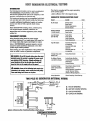
This
chart
is
compiled
with
the
engine
operating
at
the
correct
speed.
· .
Letters
A,B,C,D,
refer
to
the
diagram
below.
GENERATOR
TROUBLESHOOTING
CHART
FAULT
No
_AC
Output
Residual
Voltage
7-8
VAC
(Hot-N)
Low
AC
Output
(60-100
VAC)
High
AC
Output
Voltage
Drop
under
Motor
Load
No
Battery
Charge
Low
Battery
Charge
Unstable
Voltage
(Refer
to
Operators
Manual)
CAUSE
.
·Shorter
StatoP
Open
Stator
Shorted
Suppressors
Shorted
Diodes
Shorted
Exciter
Open
Exciter
Faulty
Rotor
Faulty
Diode
Faulty
Capacitor
Faulty
Suppressor
Incorrect
Voltage
tap
on
capacitor
Incorrect
MFD
rated
capacitor
Incorrect
Hertz
tap
on
capacitor
·
Faulty
Rotor
Diode
Faulty
Bridge
Rectifier
Faulty
Integral
Controller
Check
Fuse
Faulty
Winding
Check
Engine
S11eed
(hertz)
Adjust
Governor
Check
Capacitor
Connections
and
AC
Terminal
Wiring
(Refer
to
Wiring
Diagram)
TEST
c·
c
A
A
0
0
A
A
CAP
A
c
c
c
A
B
B
B
B
Noisy
Operation
Check
Coupling,
Check
Bearing
TWO
POLE
BC
GENERATOR
INTERNAL
WIRING
r--------.,
!AfHi
: :
~~--~
1·
I
r
I
I.
I
I
I
I
I
l
I
I·
l
I
l
c:
C
4
.
~
Drrrn
C'fS'I
ooo~J..,
L·
letters
reference-the
troubleshooting
chart
above
capacitor
~
WESTERBEKE
Engines & Generators
1
A
·ROTOR
WlijOINGS
B ·
BATfERY
CHARGE
WINDING
C
·sTATOR
WINDINGS
D
·CAPACITOR
WINDING

BCGT
GENERATOR
ElECTRICAL
TESTING
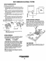
TESTING
GENERATOR
COMPONENTS
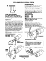
TESTING
RDmB
WINDINGS
Assume that the diodes
are
OK.
Test
the
resistance values
of
the
rotor windings
by
placing
the
multitester leads
across the diode
as
shown
and
compare to
the
data below.
Modei4.5Kw
8'"-C
----
Modei7.2Kw
BC"---'----
Model9.6Kw
BC.--'----
If
the data
is.cOIJeCt,
the problem
in
NOT
in
the rotor.
To
continue
testing,
remove fue diode/suppressor by
unsoldering the twp winding leads.
Test for resistance
between the two winding Ie3ds and again
comvare
tO
the
data.
lESTIRGTHE
WINDING
lEADS
A
CAtmON:
[ON
SOLDERING]
When
StJidering,
use
a
large
enough
soldering
iron
to
get the job
done
quicldy.
Emessire
heat will
damage
the
diodes.
A/sD
make
certain
no
soldering
splashes
ollto the
windings
as
it
will melt the
insulation.
Check for continuity between
each
of
these
leads
and
the
rotor shaft. Continuity
would indicate a short
in
the rotor.
TESTING
THE
DIODES
With
the
diodes removed, measure the resistance
(as
shown) using a multitester (with a diode testing capability).
If
the
meter
measures resistance in one direction,
it
should
indicate infinity
in
the
other.
~
TESTING
DIODES
-~
ALTERNATE
STYLE
DIODE
Both diodes should
measure
the·same.resistance value.
If
one measures
lower
than
the
other,
it
is presumed faulty.
Replace both.
TESTING
THE
SUPPRESSOR
Unsolder the suppressor from
the
diode
and
check
for
infinite resistance.
IF
THE
SUPPRESSOR
FAlLS
TO
READ
JNRNITE
RESISTANCE.
THE
SUPPRESSOR
JS
FAULTY
A shorted suppressor will often
tum
black when shorted
out.
Repeat
the
same
test procedureS to the opposite side
rotor windings.
1-.v-IWESTERBEKE
l Engines
8t
Generators
2

BCGT
GENERATOR
ELECTRICAL
TESTING
0
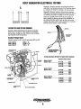
TESTING
THE
EXCITER
WINDINGS
An
AC voltage is
induCed
in these windings by
the
rotating field.
Checking
the residual voltage output
from
this winding
can
determine
the
~ondition
of
the
wfuding
when
troubleshooting.
RESIDUAL
VOLTAGE
Single
capacitor
Model
16.
~
18
VAC
from
eath
winding
AC
voltage
can
be
measured across the capacitor· while the
generator is
operating.
This
voltlc,oe
may be a5 high
as
400
to
500 volts
AC.
This
voltage buildup is accomplished
as
the exciter
windings
charge the capacitor and the capacitor
discharges back
into
the exciter windings. This AC voltage
reading
is
taken
between
the #60 Hertz connector and the
number
conneCtion
plugged
in~
the capacitor while the
generator
is operating at its rated Hertz (61.5- 62.0). This
fiow
of
saturating
AC
fu
the
exciter windings produces a
phase-imbalance
type
of
field
that effects the
auxi1lary
windings: a
beneficial
result
that
produces good motor
starting characteristics for this type
of
generator.
IDlE: Position
the
m4ter
correctly
for
AC
voltage.
so as
not
ro
damage
·the
merer.
EXCITER
CIRCUIT
RESIDUAL
VOLTAGE
Madel4.5Kw
BC
16
VAC
(:!::
.5) ·
Madel7
.2Kw
BC
17
VAC
(:!::
.5)
Madel9.6Kw
BC
18
VAC
(:!::
.5)
CIIEClCING
RESIDUAL
VOLTAGE
TESDII·AC
.
VOLTAGE
(GEIIERATOR
llUHHIIIIi)
MEASURING
RESISTANCE
To
measure the resistance value
of
the
exciter windings,
locate
#9
and the #50 Hertz capacitor connections.
NOTE:
Three
numbered capacitor connections exist: #7,
#8,
tmd #9;
and
two
Hertz
connections,
#50
and
#60.
Unplug
any
other connections from the capacitor noting
their position on
the
capacitor. Place
one
lead
of
the
multimeter
on
plug .connection
#9
and
the
other lead on
plug
connection
#50
Hertz. Measure
the
resistance value
of
the exciter windings.
WINDING
RESISTANCE
[OHMS}
Modei4.SKw
BC
4.550
Ma~7~wBC
3J&Q
Madel9.6Kw
BC
3.710
NOTE:
Lower residual
voltag~
along with ti lower winding
resistimce.
will confirm aftmlty
winding.
CIIECDIG.
COtmiUITY
·
check to make sure there is no continuity
to
the
ground/generator case
from
either
of
the
two
leads.
Also check tbat no continuity exists between either
the
#60
Hettt plug
or
the
#8
plug
an~
any of the main stator
.winding leads on the AC output (not illustrated).
If
continuity is found here. a fault exists between
these:
two'~
winding groups. -
~~
DISCHARG.
THE
CAPACRORS
A
CAOTIOI:
t:apacifDIS
miiSI
be
dist:barged
before
fesfillg. t:apat:ifllls sfiii'B elet:lrit:ify
ami
t:aiJ
pat:lc
a lethal
1111111:11
eren
when
f/iSI:IInner:ted
tr11111
the
power
Sllllf't:e. . .
· Discharge the capacitor by a bridging the terminals with a
screwdriver.
l"'fiiiV'IWESiiRBEKE
. ) Engines & Generators
3

BCGT
GENERATOR
ELECTRICAL
TESTING
TESTING
THE
CAPACITORS
Connect
a multitester (highest ohm scale) to the capacitor
terminals.
The meter
should
go to zero
ohms
and slowly
return
to
high.
DisCharge
the
capacitor again and reverse
the
leads.
the
same
results
should
b~
obtained.
If
the
meter
.goes
down
and
stays
at
zero ohms, the capaci-
tor is faulty (shorted).
If
the
meter
fails
to
go
down
to zero, the capacitor
is.
faulty
{open
ciicuited).
Indications of a defective capacitor:
0 Infinite resistance,
or
no
rise in resistance
(shorted capacitor)
0
Infinite
resistance
(open
capacitor)
CAPACITOR
RATINGS
I
PART
NUMBERS
Model
4.5
Kw
BC
25
mfd
Pn#035985
Model
7.2
Kw
BC
31.5
mfd
Pnt/035978
Model
9.6
Kw
BC
35
mfd
Pn#041199
NOTe:
MAKE
CERTAIN
A
REPLACEMENT
CAPACITOR
HAS
THE
CORRECT
PART
NUMBER.
CHECK
THE
BODY
OF
THE
CAPACITOR
FOR
THE
RATING~
NOD.:
The
co.pocitor
rating
is~
on
the_
\ousmg
12
VOLT
EXCITAnON
The
generatOr
may
be
excited using 12
.volts
DC
taken
from the engine's starting battety.
This
voltage
is
applied
across
the
:#1:50
and
#9
leads
of
the exciter circuit windings
(unplugged)
with
any
other numbered leads unplugged
from the capacitors.
The
generator's
reaction during flash-
ing
will
help
detemUne
i~
fault. ·
12
VOLT
EXCrTAnON,
OUTPUT
RANGE
IS
22
TO
26
VAC.
0 A slight
rise
in
the
output.
voltage
with
the loading
of
the
engine and/or a growling noise from the generator
end will indicate a
fault
in the main stator windings.
0
No
rise
or a very slight rise
in
the output voltage
will
indicate a fault in the excitor windings.
0 Normal output voltage
as
specified above, check
excitor circuit
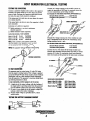
TESTING
THE
BA1TERY
CHARGING·CIRCUIT
:
Normal
AC
voltage running to tberecti1ier (while the
engine
is operating
at
3600
rpm)
is measured across the
two
AC
connections
o~
the bridge rectifier.
AC
VOLTAGE
TO
THE
BRIDGE
RECTIAER
(APPROXIMATELY):
No-load off
1he
generator
16.0
volts
AC
FIJU-Ioad
off the generator 17.5
volts
AC
BRIDGE
RECnFIER
Normal
DC
voltage running out
of
the
rectifier (in· volts
DC)
is
measured across the two
DC
connections
of
the
bridge
rectifier, that
is+
and-.
DC
VOLTAGE
FROM
THE
BRIDGE
RECnAER
fAPPROXIMATaY):
No-load
off
.the
generator
17
.o·
volts
DC
. .
FIJH-Ioad
off
the
generator 18.5
volts
DC
Uft
the
tw~
AC
wire
I'eacis
off the bridge rectifier and
measure the resistance between these two leads.
It
should
measure 0.14
ohm. No continuity should exist
~tween
there two leads and the ground
or.
the main stator windings.
ACLEAD
RESISTANCE
MEASUREMENT
Modei4.5Kw
BC@
60Hz
Model7
.2Kw
BC
@60Hz
@50Hz
Model
9.6Kw
BC
0
60Hz
@5oHz
.1570
Blue
to
Blue
.0940
Blue
to
Green
.1160
Blue
to
White
.O&Ul
Green
to
Blue
.10&n
.Blue
to
Wbite
ACTEKMINAL
I....,.I!ESI"ERBEICE
)Engines
& Generators
4

BCGT
GENERATOR
ELECTRICAL
TESTING
TESTING
THE
.BRIDGE
RECnFIER
(meter
used
- FLUKE
multim~ter)
.
A.
Set the meter
on
Ohms
scale.
B.
Connect
the positive (
+)
lead from the meter
to
point
#4.
Taking
the negative
(-)
lead, momentarily touch points
#1,
#2,
#3,
and
#5.
There
should
be
no
Ohm
value registered
on
the
meter.
C.
Remove
the
positive (+) lead from point #4
and
connect the
negativ~
(-) lead to
it
Momentarily touch
poin~
#1, #2
and
#3.
the
Qhm
meter should register
an
arbitrary
Ohm
value
at
each
point it touches.
D.
Leaving
the negative
(-)
lead
on
point #4, touch point
#5
with
the
positive ( +) lead. The meter should register
no
Ohm
value.
E.
Place
the positive(+) lead on point
#1
and
the negative(-)
lead
on
point #3. The meter again should register no
Ohm
value.
Reverse these connections and the meter should
register
no
Ohm
value.
If
the
rectifier fails
any
of
the
previous
tests B
through
E, replace
the
rectifier as
it
is defective. . #i. .
BRIDGE
~',
RECTIFIER
#4.
#3
when
Viewed
from
the top
Nlln:
Different
types
anillor
brands
of
test
meters
may
produce
opposite
test
results.
INTEGRAL
CORTROUER
The Integral Controller (LC.) is an encapsulated. solid-state
unit that
suppli~
a DC charging voltage to the generator's
starting
battery
while
the
generator is operating.
Charging
Voltage
13.0
-14.0
volts
DC
Charging
Amperage
0 -
17.0
amps
DC
A
seperate
group
of
stator
windings
supplies AC voltage to
a
brid~e
rectifier
which
converts the AC
cUITent
to supply
the
LC.
unit
The I.
C.
unit senses the
needS
of the starting
battery
and
supplies a DC charge when one is needed.
If
you
suspect
that
the
LC.
unit is faulty
(that
is,
if
the
battery's
charge
is
low), check the charging circuit and it's
·
components
as
described in
the
following
text
Check
all
connections
for
cleanliness and tightness including the
ground
before
replacing
the
I.C. uniL
NOTE:
When
the
generQlOr
is first staned, the LC. unit will
produce
a
low
charging
rate.
This
charging
rate
will
rise
as
the
generator
is
operated.
#2,
INTEGRAL
CONTROUER
--"'-1+
+
-
G'ND
AC
TESTING
THE
INTEGRAL
COITROUER
BRIDGE
RECTIAER
To
test the
battery
charger, put a multimeter between
the
positive ( +) and negative (-) leads to the battery. It
should
indicate 13.5V to
14V
with the engine running.
If
only
the
battery voltage
is
indicated, check that the battery
charger
teri:ninal
connections are
tight
With the unit running,
test
between
the
(+)
and (-) terminals for 13.5V
to
14V.
If
no
charge ia indicated, replace the charger.
FUSE
PROTECnDN
A 30 amp fuse protects the windings from a failure
of
the
bridge rectifier or integral controller (high amperage
or
a
short).
I..,...,.IWESJERBSCE
(Engines & Generators
5

BCGT
GENERATOR
ELECTRICAL
TESTING
TESTING
THE
MAIN
STATOR
WINDINGS
Residual voltage measured between the bot and neutral
leads will
be
7-8 volts AC. This.would be an indication
that the stator windings are okay. Check exciter windings
·and
artiQcially excite
the
generator..
Residual
Voltage
Check
Measure between bot
[#1
and #4] and neutral [#2 and #5].
Model4.5Kw
BC
8
VAC
(::!:
.5)
Model7
.2Kw
BC
7.5
VAC
(::!:
.5)
Model
9.6Kw
BC
7
·vAc
(:!:
.5)
IS
FASTERSIS
TO
STUD
Group
#1
- Measure resistance value between terminal
with lead
#l
and terminal with lead #3. (Check that there
is
no continuity
of
Group
#1
windings to
the
case
ground).
Group
#2
- Measure resistance value between terminal
with
lead
:fl:4
and terminal with lead #6. (Check that there
is
no continuity
of
group #2 windings to the case ground).
Check for a possible short between the
two
groups
of
stator windings by placing one lead
of
the multitester
on
the terminal with
the
stator #3 and the other lead
on
the
terminal with stator lead #6. There should be no continuity
between the two groups
of
stator windings.
MAIN
STATOR
WINDINGS
TESliNG
RESISTANCE
BETWEEN
THE
MAIN
STATOR
WINDINGS
Resistance
Valpes
[ohms]
Mode14.5Kw
BC
Between
lead$
____
11
and
12
___
.5150
11
and
#3
.5850 .
i4
and
i5
.5160
i4
and
16 .58SQ
Model7
.2Kw
BC
Between
leads
____
l1
and
l2
___
.294n
11
and
13
.330Q
i4
and
i5
.2930
i4
and
16 .331n
Model
9.6Kw
BC
Between
leads
____
i1
and
l2
___
.179n
11
and
13
.200Q
i4
and
15
.179n
i4
and
16 .201n
t....,-IWESIERBEICE
. · l Engines & Generators
6

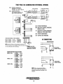
TWO
POLE
BC
GENERATOR
INTERNAL
WIRING
FUSE·
INTEGRAL
CONTROLLER
WINDING:
NO
TIM£
DELAY
Pn#43634
30A
250V
MDA-30
FUSE
•
ENGINE
PROTECTION
30A
(NOT
SHOWN)
Pn#33769
BA
250V
MTH-8
(TIME
DELAY)
r--------.,
B
UA.,-...,.1
I · I
lAR)j
I . I
I I
1·
1
I J
I I
1 I
I I
1 l
\ARJj
I I
I I
BRIDGE
RECTIFIER
A
..
ROTOR
WINDINGS
B •
BATTERY
CHARGE
WINDING
MODEL4.5Kw
ID
..
BATTERY
CHARGE
WINDING
MODELS
7.2Kw
AND
9.6Kw
C
·STATOR
WINDINGS
----------
11-----os
D
..
CAPACITOR
WINDING
UA-----os
CAPACITOR
RATINGS
I
PART
NUMBERS
Model4.5
Kw
BC
25
mtd
Pn#035985
Drrrn
Model?
.2
Kw
BC
31.5
mfd
Pn#035978
9 8 1
Model9.6
Kw
BC
35
mfd
Pn#041199
0 0 0
;
L:f
50Hz
NOTE:
MAKE
CERTAIN
A
REPLACEMENT
CAPACITOR
HAS
THE
CORRECT
PART
NUMBER.
CHECK
THE
BODY
OF
THE
CAPACITOR
FOR
THE
RATING.
CONNECT
FOR
1HE
REQUIRED
FREQUENCY
AND
OUTPUT
VOL
'lAG£
WINDING
RESISTANCE
VALUES
IN
OHMS
MODEl
4.5Kw
A
ROTOR
3.51!2
B
CHARGER
0.14!2
C
STATOR
0.58!2
D
EXCITER
2.3!2
MODEl
7.2Kw
A
ROTOR
3.51!2
8
CHARGER
0.14!2
. C
STATOR
0.29!2
D
EXCITER
2.20
MODEl9.6Kw
A
ROTOR
4.03!2
B
CHARGER
0.14!2
C
STATOR
0.17!2
AC
CONNECTIONS
CIRCUIT
BREAKER
:?1
- N
-
L
1-.------------~
s.--------,
~=
D
EXCITER
1.9!2
NOTE:
When
changing
from
60Hz
to
-50Hz.
make ceriain the ground wire is
properly
repositioned according to this
diagram.
N L
1-w'IWESTERBEKE
) Engines & Generators
7
12DVAC60Hz
(CONNECT
JUMPER)
230VAC50Hz
.
{REMOVE
JUMPER)


-
 1
1
-
 2
2
-
 3
3
-
 4
4
-
 5
5
-
 6
6
-
 7
7
-
 8
8
-
 9
9
-
 10
10
-
 11
11
-
 12
12


Westerbeke 7.0 BCDT - 50 Hz Guía del usuario
- Tipo
- Guía del usuario
en otros idiomas
Otros documentos
-
WEG AG10 Serie Manual de usuario
-
Hobart 5359D Operation and Maintenance Manual
-
-
Sincro FB4 Use and Maintenance Manual
-
 COOLRUN MUNICAP200 Guía de instalación
-
Campbell Hausfeld GW4502 Instrucciones de operación
-
Campbell Hausfeld GR2100 Manual de usuario
-
Campbell Hausfeld GN30c502AC Manual de usuario
-
-
