
APPLICATIONS
METRA. The World’s best kits.
™
metraonline.com1-800-221-0932
© COPYRIGHT 2004-2013 METRA ELECTRONICS CORPORATION
REV. 7/21/2014 INST99-8214
CAUTION: Metra recommends disconnecting the
negative battery terminal before beginning any
installation. All accessories, switches, and especially
air bag indicator lights must be plugged in before
reconnecting the battery or cycling the ignition.
NOTE: Refer to the instructions included with the
aftermarket radio.
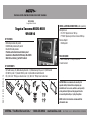
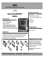
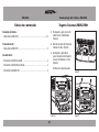
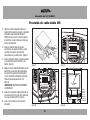
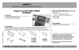
INSTALLATION INSTRUCTIONS FOR PART 99-8214
• DIN radio provision with pocket
• ISO DIN radio provision with pocket
• Double DIN radio provision
• Painted and textured to match factory dash
• Available in: Black 99-8214TB or Gray 99-8214TG
• Both kits are factory “golf ball” textured
KIT FEATURES
WIRING & ANTENNA CONNECTIONS (sold separately)
Wiring Harness:
• 70-1761 Toyota harness 1987-up
• TYTO-01 Toyota amp interface harness 2003-up
Antenna Adapter:
• Not Required
• Panel removal tool • Phillips screwdriver
• Socket wrench
TOOLS REQUIRED
Toyota Tacoma 2005-2011
99-8214
See application list inside
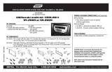
• A) Radio housing • B) Radio housing brackets • C) Radio housing trim panel • D) ISO Brackets
• E) ISO Trim plate • F) Double DIN trim plate • G) Clock/Hazard switch bracket
• H) (4) #6 x 3/8” Phillips pan head screws • I) (4) #8 X 3/8” Phillips truss head screws
KIT COMPONENTS
B C D
E F
A
IG H

2
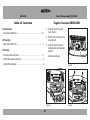
Dash Disassembly
– Toyota Tacoma 2005-2011 .............................................................................. 2-3
Kit Preparation
– Toyota Tacoma 2005-2011 ..................................................................................3
Kit Assembly
– DIN radio provision with pocket ...........................................................................4
– ISO DIN radio provision with pocket .....................................................................5
– Double DIN radio provision ...................................................................................6
Table of Contents
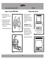
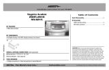
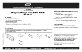
1. Unclip and remove A/C control
panel. (Figure A)
2. Remove (4) 10 mm bolts securing
radio. (Figure B)
3. Unclip and remove entire panel
including hazard switch and clock.
(Figure C)
Continued on next page
Toyota Tacoma 2005-2011
(Figure C)
(Figure B)
99-8214 Dash Disassembly 99-8214
SCAN
TEXT
PWR VOL
(Figure A)
SCAN
TEXT
PWR VOL

3
Dash Disassembly 99-8214
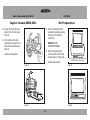
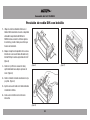
4. Remove the left and right radio
brackets from the radio chassis.
(Figure D)
5. Unclip and remove the clock/
hazard switch assembly from the
factory radio housing trim panel.
(Figure E)
Continue to kit preparation
Toyota Tacoma 2005-2011
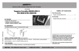
1. Attach the clock/hazard switch
bracket to the radio housing using
the (4) #6 x 3/8” Phillips pan
head screws.
WARNING: DO NOT
OVERTIGHTEN SCREWS.
2. Clip the clock/hazard switch
assembly into the 99-8214 radio
housing trim panel. (Figure A, B)
Continue to kit assembly
Kit Preparation
(Figure E)
(Figure D)
99-8214
(Figure B)
(Figure A)
H
M
PASSENGER
PASSENGER
H
M
PASSENGER
PASSENGER
INSERT CLOCK/HAZARD SWITCH ASSEMBLY
FROM REAR OF 99-8214 RADIO HOUSING TRIM PANEL
Insert clock/hazard switch assembly from rear
of 99-8214 radio housing trim panel

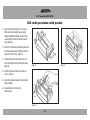
DIN radio provision with pocket
4
Kit Assembly 99-8214
1. Locate the factory wiring harness in the dash.
Metra recommends using the proper mating
adapter from Metra or AXXESS. Re-connect the
negative battery terminal and test the radio for
proper operation.
2. Attach the corresponding radio housing bracket to
the radio housing using the included (4) #8 x 3/8”
Phillips truss head screws. (Figure A)
3. Slide the DIN cage into the radio housing and
secure by bending the metal locking tabs down.
(Figure B)
4. Slide the aftermarket radio into the cage and
secure. (Figure C)
5. Secure the radio housing into the dash using the
factory hardware.
6. Reassemble dash in reverse order
of disassembly.
(Figure B)
(Figure A) (Figure C)

99-8214
5
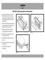
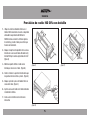
ISO DIN radio provision with pocket
1. Locate the factory wiring harness in the dash.
Metra recommends using the proper mating
adapter from Metra or AXXESS. Re-connect the
negative battery terminal and test the radio for
proper operation.
2. Attach the corresponding radio housing bracket to
the radio housing using the included (4) #8 x 3/8”
Phillips truss head screws. (Figure A)
3. Mount the ISO brackets to the radio with the
screws supplied with the radio. (Figure B)
4. Slide the radio into the radio opening until the
side clips engage. (Figure C)
5. Snap the ISO trim plate into the radio housing.
(Figure C)
6. Secure the radio housing into the dash using the
factory hardware.
7. Reassemble dash in reverse order
of disassembly.
(Figure B)
(Figure A) (Figure C)
Right side clip

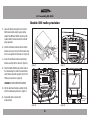
Double DIN radio provision
6
Kit Assembly 99-8214
1. Locate the factory wiring harness in the dash.
Metra recommends using the proper mating
adapter from Metra or AXXESS. Re-connect the
negative battery terminal and test the radio for
proper operation.
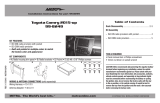
2. Slide the aftermarket radio unit into the factory
brackets and secure the unit to the brackets using
the screws supplied with the head unit. (Figure A)
3. Secure the aftermarket radio unit and factory
bracket assembly into the sub dash. (Figure B)
4. Place the Double DIN trim plate into the back of
the radio housing, then attach the clock/hazard
switch bracket assembly using the (4) #6 x 3/8”
Phillips pan head screws. (Figure C)
WARNING: DO NOT OVERTIGHTEN SCREWS.
5. Clip the clock/hazard switch assembly into the
99-8214 radio housing trim panel. (Figure D)
6. Reassemble dash in reverse order
of disassembly.
(Figure B)
(Figure A)
(Figure D)
(Figure C)
RESTORE
CLOCK/HAZARD SWITCH
BRACKET ASSEMBLY
RESTORE
CLOCK/HAZARD SWITCH
BRACKET ASSEMBLY
REAR VIEW OF
RADIO HOUSING
DOUBLE DIN TRIM PLATE
Double DIN
trim plate
Rear view
of radio
housing
Restore
clock/hazard
switch racket
assembly

99-8214
7
Notes

METRA. The World’s best kits.
™
metraonline.com1-800-221-0932
© COPYRIGHT 2004-2013 METRA ELECTRONICS CORPORATION
REV. 7/21/2014 INST99-8214
KNOWLEDGE IS POWER
Enhance your installation and fabrication skills by
enrolling in the most recognized and respected
mobile electronics school in our industry.
Log onto www.installerinstitute.com or call
800-354-6782 for more information and take steps
toward a better tomorrow.
Metra recommends MECP
certified technicians
INSTALLATION INSTRUCTIONS FOR PART 99-8214

APLICACIONES
METRA. The World’s best kits.
™
metraonline.com1-800-221-0932
© COPYRIGHT 2004-2013 METRA ELECTRONICS CORPORATION
REV. 7/21/2014 INST99-8214
PRECAUCIÓN: Metra recomienda desconectar el terminal
negativo de la batería antes de comenzar cualquier
instalación. Todos los accesorios, interruptores y,
especialmente, las luces indicadoras de airbag deben
estar enchufados antes de volver a conectar la batería o
comenzar el ciclo de ignición.
NOTA: Remítase a las instrucciones incluidas con el
radio de postventa.
INSTRUCCIONES DE INSTALACIÓN PARA LA PIEZA 99-8214
• Provisión de radio DIN con bolsillo
• Provisión de radio ISO DIN con bolsillo
• Provisión de radio doble DIN
• Pintura y textura que igualan el tablero de fábrica
• Disponible en: Negro 99-8214TB o gris 99-8214TG
• Ambos kits tienen textura de “pelota de golf” de fábrica
CARACTERÍSTICAS DEL KIT
• Herramienta de remoción de panel • Destornillador
Phillips • Llave de tubo
HERRAMIENTAS REQUERIDAS
Toyota Tacoma 2005-2011
99-8214
Lista de aplicaciones dentro
CABLEADO Y CONEXIONES DE ANTENA
Arnés de cableado:
• 70-1761 - Toyota 1987 y más recientes
• TYTO-01- Interfase para amplificador para Toyota
2003 y más
Adaptador de antena:
• No se requiere
(se venden por separado)
• A) Carcasa del radio • B) Soportes de la carcasa del radio • C) Panel de moldura de la carcasa del radio
• D) Soportes ISO • E) Placa de moldura ISO • F) Placa de moldura doble DIN • G) Soporte de reloj/
interruptor de luces intermitentes • H) (4) tornillos Phillips de cabeza troncocónica #6 x 3/8”
• I) (4) tornillos Phillips de cabeza segmentada #8 X 3/8”
COMPONENTES DEL KIT
B C D
E F
A
IG H

2
Desmontaje del tablero
– Toyota Tacoma 2005-2011 .............................................................................. 2-3
Preparación del kit
– Toyota Tacoma 2005-2011 ..................................................................................3
Ensamble del kit
– Provisión de radio DIN con bolsillo .......................................................................4
– Provisión de radio ISO DIN con bolsillo .................................................................5
– Provisión de radio doble DIN ................................................................................6
Tabla de contenido
1. Desenganche y quite el panel del
control del aire acondicionado.
(Figura A)
2. Quite los (4) pernos de 10 mm que
sostienen el radio. (Figura B)
3. Desenganche y quite todo el
panel, incluyendo el interruptor de
las luces intermitentes y el reloj.
(Figura C)
Continúa en la siguiente página.
Toyota Tacoma 2005-2011
(Figura C)
(Figura B)
99-8214 Desmontaje del tablero 99-8214
SCAN
TEXT
PWR VOL
(Figura A)
SCAN
TEXT
PWR VOL

3
Desmontaje del tablero 99-8214
4. Quite los soportes del radio
izquierdo y derecho del chasís del
radio. (Figura D)
5. Desenganche y quite el conjunto
del reloj/interruptor de las luces
intermitentes del panel de la
moldura de la carcasa del radio de
fábrica. (Figura E)
Continúe con la preparación del kit
Toyota Tacoma 2005-2011
1. Coloque el soporte del reloj/
interruptor de las luces
intermitentes en la carcasa del
radio utilizando los (4) tornillos
Phillips de cabeza troncocónica
#6 x 3/8”.
ADVERTENCIA: NO APRIETE
EXCESIVAMENTE LOS TORNILLOS.
2. Enganche el conjunto del
reloj/interruptor de las luces
intermitentes en el panel de la
moldura de la carcasa del radio
99-8214. (Figura A, B)
Continúe con el ensamble del kit
Preparación del kit
(Figura E)
(Figura D)
99-8214
(Figura B)
(Figura A)
H
M
PASSENGER
PASSENGER
H
M
PASSENGER
PASSENGER
INSERT CLOCK/HAZARD SWITCH ASSEMBLY
FROM REAR OF 99-8214 RADIO HOUSING TRIM PANEL
Inserte el conjunto del reloj/interruptor
de las luces intermitentes desde la parte
trasera del panel de la moldura de la
carcasa del radio 99-8214

Provisión de radio DIN con bolsillo
4
Ensamble del kit 99-8214
1. Ubique el arnés de cableado de fábrica en el
tablero. Metra recomienda el uso de un adaptador
adecuado de acoplamiento de Metra o de
AXXESS. Vuelva a conectar la terminal negativa
de la batería y pruebe el radio para verificar que
funcione correctamente.
2. Coloque el soporte correspondiente de la carcasa
del radio en la carcasa del radio utilizando los (4)
tornillos Phillips de cabeza segmentada #8 x 3/8”.
(Figura A)
3. Deslice la reja DIN en la carcasa del radio y
sujétela doblando hacia abajo las pestañas de
metal. (Figura B)
4. Deslice el radio de mercado secundario en la reja
y sujételo. (Figura C)
5. Sujete la carcasa del radio en el tablero utilizando
la tornillería de fábrica.
6. Vuelva a armar el tablero al revés de como
lo desarmó.
(Figura B)
(Figura A) (Figura C)

99-8214
5
Provisión de radio ISO DIN con bolsillo
1. Ubique el arnés de cableado de fábrica en el
tablero. Metra recomienda el uso de un adaptador
adecuado de acoplamiento de Metra o de
AXXESS. Vuelva a conectar la terminal negativa
de la batería y pruebe el radio para verificar que
funcione correctamente.
2. Coloque el soporte correspondiente de la carcasa
del radio en la carcasa del radio utilizando los (4)
tornillos Phillips de cabeza segmentada #8 x 3/8”.
(Figura A)
3. Monte los soportes ISO en el radio con los
tornillos que vienen con el radio. (Figura B)
4. Deslice el radio en la apertura del radio hasta que
los ganchos laterales entren a presión. (Figura C)
5. Coloque a presión la placa de moldura ISO en la
carcasa del radio. (Figura C)
6. Sujete la carcasa del radio en el tablero utilizando
la tornillería de fábrica.
7. Vuelva a armar el tablero al revés de como
lo desarmó.
(Figura B)
(Figura A) (Figura C)
Right side clip

Provisión de radio doble DIN
6
Ensamble del kit 99-8214
1. Ubique el arnés de cableado de fábrica en el
tablero. Metra recomienda el uso de un adaptador
adecuado de acoplamiento de Metra o de
AXXESS. Vuelva a conectar la terminal negativa
de la batería y pruebe el radio para verificar que
funcione correctamente.
2. Deslice la unidad del radio de mercado
secundario en los soportes de fábrica y sujete
la unidad a los soportes con los tornillos
suministrados con la unidad central. (Figura A)
3. Sujete la unidad del radio de mercado secundario
y el ensamble del soporte de fábrica al sub
tablero. (Figura B)
4. Coloque la placa de moldura doble DIN en la parte
posterior de la carcasa del radio, luego coloque
el ensamble del soporte del reloj/interruptor de
las luces intermitentes utilizando los (4) tornillos
Phillips de cabeza troncocónica #6 x 3/8”.
(Figura C)
ADVERTENCIA: NO APRIETE EXCESIVAMENTE
LOS TORNILLOS.
5. Enganche el conjunto del reloj/interruptor de las
luces intermitentes en el panel de la moldura de
la carcasa del radio 99-8214. (Figura D)
6. Vuelva a armar el tablero al revés de como
lo desarmó.
(Figura B)
(Figura A)
(Figura D)
(Figura C)
RESTORE
CLOCK/HAZARD SWITCH
BRACKET ASSEMBLY
RESTORE
CLOCK/HAZARD SWITCH
BRACKET ASSEMBLY
REAR VIEW OF
RADIO HOUSING
DOUBLE DIN TRIM PLATE
Placa de moldura
doble DIN
Vista
posterior de
la carcasa
del radio
Vuelva a
colocar el
ensamble
del reloj/
interruptor
de las luces
intermitentes

99-8214
7
Notas

METRA. The World’s best kits.
™
metraonline.com1-800-221-0932
© COPYRIGHT 2004-2013 METRA ELECTRONICS CORPORATION
REV. 7/21/2014 INST99-8214
KNOWLEDGE IS POWER
Enhance your installation and fabrication skills by
enrolling in the most recognized and respected
mobile electronics school in our industry.
Log onto www.installerinstitute.com or call
800-354-6782 for more information and take steps
toward a better tomorrow.
Metra recomienda técnicos
con certificación del Programa
de Certificación en Electrónica
Móvil (Mobile Electronics
Certification Program, MECP).
EL CONOCIMIENTO ES PODER
Mejore sus habilidades de instalación y
fabricación inscribiéndose en la escuela de
dispositivos electrónicos móviles más reconocida
y respetada de nuestra industria. Regístrese en
www.installerinstitute.com o llame al
800-354-6782 para obtener más información y
avance hacia un futuro mejor.
INSTRUCCIONES DE INSTALACIÓN PARA LA PIEZA 99-8214
Transcripción de documentos
INSTALLATION INSTRUCTIONS FOR PART 99-8214 APPLICATIONS See application list inside WIRING & ANTENNA CONNECTIONS (sold separately) Wiring Harness: • 70-1761 Toyota harness 1987-up • TYTO-01 Toyota amp interface harness 2003-up Antenna Adapter: • Not Required Toyota Tacoma 2005-2011 99-8214 REV. 7/21/2014 INST99-8214 KIT FEATURES • DIN radio provision with pocket • ISO DIN radio provision with pocket • Double DIN radio provision • Painted and textured to match factory dash • Available in: Black 99-8214TB or Gray 99-8214TG • Both kits are factory “golf ball” textured TOOLS REQUIRED • Panel removal tool • Phillips screwdriver • Socket wrench KIT COMPONENTS • A) Radio housing • B) Radio housing brackets • C) Radio housing trim panel • D) ISO Brackets • E) ISO Trim plate • F) Double DIN trim plate • G) Clock/Hazard switch bracket • H) (4) #6 x 3/8” Phillips pan head screws • I) (4) #8 X 3/8” Phillips truss head screws A B C G D E H I F CAUTION: Metra recommends disconnecting the negative battery terminal before beginning any installation. All accessories, switches, and especially air bag indicator lights must be plugged in before reconnecting the battery or cycling the ignition. NOTE: Refer to the instructions included with the aftermarket radio. METRA. The World’s best kits.™ 1-800-221-0932 metraonline.com © COPYRIGHT 2004-2013 METRA ELECTRONICS CORPORATION 99-8214 Dash Disassembly 99-8214 Table of Contents Toyota Tacoma 2005-2011 Dash Disassembly – Toyota Tacoma 2005-2011............................................................................... 2-3 1. Unclip and remove A/C control panel. (Figure A) Kit Preparation 2. Remove (4) 10 mm bolts securing radio. (Figure B) – Toyota Tacoma 2005-2011...................................................................................3 Kit Assembly 3. Unclip and remove entire panel including hazard switch and clock. (Figure C) – DIN radio provision with pocket............................................................................4 Continued on next page – ISO DIN radio provision with pocket......................................................................5 – Double DIN radio provision....................................................................................6 (Figure B) TEXT PWR VOL TEXT PWR VOL SCAN SCAN (Figure A) 2 (Figure C) Dash Disassembly 99-8214 99-8214 Toyota Tacoma 2005-2011 Kit Preparation 4. Remove the left and right radio brackets from the radio chassis. (Figure D) 1. Attach the clock/hazard switch bracket to the radio housing using the (4) #6 x 3/8” Phillips pan head screws. 5. Unclip and remove the clock/ hazard switch assembly from the factory radio housing trim panel. (Figure E) WARNING: DO NOT OVERTIGHTEN SCREWS. 2. Clip the clock/hazard switch assembly into the 99-8214 radio housing trim panel. (Figure A, B) Continue to kit preparation (Figure D) Continue to kit assembly H M PASSENGER PASSENGER INSERT CLOCK/HAZARD ASSEMBLY Insert clock/hazard switchSWITCH assembly from rear REAR OF 99-8214 RADIO HOUSING TRIM PANEL ofFROM 99-8214 radio housing trim panel (Figure A) H M (Figure E) (Figure B) 3 PASSENGER PASSENGER Kit Assembly 99-8214 DIN radio provision with pocket 1. Locate the factory wiring harness in the dash. Metra recommends using the proper mating adapter from Metra or AXXESS. Re-connect the negative battery terminal and test the radio for proper operation. 2. Attach the corresponding radio housing bracket to the radio housing using the included (4) #8 x 3/8” Phillips truss head screws. (Figure A) 3. Slide the DIN cage into the radio housing and secure by bending the metal locking tabs down. (Figure B) (Figure A) (Figure C) 4. Slide the aftermarket radio into the cage and secure. (Figure C) 5. Secure the radio housing into the dash using the factory hardware. 6. Reassemble dash in reverse order of disassembly. (Figure B) 4 99-8214 ISO DIN radio provision with pocket 1. Locate the factory wiring harness in the dash. Metra recommends using the proper mating adapter from Metra or AXXESS. Re-connect the negative battery terminal and test the radio for proper operation. 2. Attach the corresponding radio housing bracket to the radio housing using the included (4) #8 x 3/8” Phillips truss head screws. (Figure A) 3. Mount the ISO brackets to the radio with the screws supplied with the radio. (Figure B) 4. Slide the radio into the radio opening until the side clips engage. (Figure C) Right side clip (Figure A) (Figure C) 5. Snap the ISO trim plate into the radio housing. (Figure C) 6. Secure the radio housing into the dash using the factory hardware. 7. Reassemble dash in reverse order of disassembly. (Figure B) 5 Kit Assembly 99-8214 Double DIN radio provision 1. Locate the factory wiring harness in the dash. Metra recommends using the proper mating adapter from Metra or AXXESS. Re-connect the negative battery terminal and test the radio for proper operation. 2. Slide the aftermarket radio unit into the factory brackets and secure the unit to the brackets using the screws supplied with the head unit. (Figure A) 3. Secure the aftermarket radio unit and factory bracket assembly into the sub dash. (Figure B) 4. Place the Double DIN trim plate into the back of the radio housing, then attach the clock/hazard switch bracket assembly using the (4) #6 x 3/8” Phillips pan head screws. (Figure C) (Figure A) (Figure C) Rear view of radio housing WARNING: DO NOT OVERTIGHTEN SCREWS. REAR VIEW OF RADIO HOUSING DOUBLE DIN TRIM PLATE Double DIN trim plate 5. Clip the clock/hazard switch assembly into the 99-8214 radio housing trim panel. (Figure D) 6. Reassemble dash in reverse order of disassembly. RESTORE CLOCK/HAZARD SWITCH BRACKET ASSEMBLY (Figure B) (Figure D) 6 RESTORE CLOCK/HAZARD SWITCH BRACKET ASSEMBLY Restore clock/hazard switch racket assembly 99-8214 Notes 7 INSTALLATION INSTRUCTIONS FOR PART 99-8214 KNOWLEDGE IS POWER REV. 7/21/2014 INST99-8214 Enhance your installation and fabrication skills by enrolling in the most recognized and respected mobile electronics school in our industry. Log onto www.installerinstitute.com or call 800-354-6782 for more information and take steps toward a better tomorrow. Metra recommends MECP certified technicians METRA. The World’s best kits.™ 1-800-221-0932 metraonline.com © COPYRIGHT 2004-2013 METRA ELECTRONICS CORPORATION INSTRUCCIONES DE INSTALACIÓN PARA LA PIEZA 99-8214 APLICACIONES Lista de aplicaciones dentro CABLEADO Y CONEXIONES DE ANTENA (se venden por separado) Arnés de cableado: • 70-1761 - Toyota 1987 y más recientes • TYTO-01- Interfase para amplificador para Toyota 2003 y más Adaptador de antena: • No se requiere Toyota Tacoma 2005-2011 99-8214 REV. 7/21/2014 INST99-8214 CARACTERÍSTICAS DEL KIT • Provisión de radio DIN con bolsillo • Provisión de radio ISO DIN con bolsillo • Provisión de radio doble DIN • Pintura y textura que igualan el tablero de fábrica • Disponible en: Negro 99-8214TB o gris 99-8214TG • Ambos kits tienen textura de “pelota de golf” de fábrica HERRAMIENTAS REQUERIDAS • Herramienta de remoción de panel • Destornillador Phillips • Llave de tubo COMPONENTES DEL KIT • A) Carcasa del radio • B) Soportes de la carcasa del radio • C) Panel de moldura de la carcasa del radio • D) Soportes ISO • E) Placa de moldura ISO • F) Placa de moldura doble DIN • G) Soporte de reloj/ interruptor de luces intermitentes • H) (4) tornillos Phillips de cabeza troncocónica #6 x 3/8” • I) (4) tornillos Phillips de cabeza segmentada #8 X 3/8” A B C G D E H I F PRECAUCIÓN: Metra recomienda desconectar el terminal negativo de la batería antes de comenzar cualquier instalación. Todos los accesorios, interruptores y, especialmente, las luces indicadoras de airbag deben estar enchufados antes de volver a conectar la batería o comenzar el ciclo de ignición. NOTA: Remítase a las instrucciones incluidas con el radio de postventa. METRA. The World’s best kits.™ 1-800-221-0932 metraonline.com © COPYRIGHT 2004-2013 METRA ELECTRONICS CORPORATION 99-8214 Desmontaje del tablero 99-8214 Tabla de contenido Toyota Tacoma 2005-2011 Desmontaje del tablero 1. Desenganche y quite el panel del control del aire acondicionado. (Figura A) – Toyota Tacoma 2005-2011............................................................................... 2-3 Preparación del kit 2. Quite los (4) pernos de 10 mm que sostienen el radio. (Figura B) – Toyota Tacoma 2005-2011...................................................................................3 3. Desenganche y quite todo el panel, incluyendo el interruptor de las luces intermitentes y el reloj. (Figura C) Ensamble del kit – Provisión de radio DIN con bolsillo........................................................................4 – Provisión de radio ISO DIN con bolsillo..................................................................5 – Provisión de radio doble DIN.................................................................................6 Continúa en la siguiente página. (Figura B) TEXT PWR VOL TEXT PWR VOL SCAN SCAN (Figura A) 2 (Figura C) Desmontaje del tablero 99-8214 99-8214 Toyota Tacoma 2005-2011 Preparación del kit 4. Quite los soportes del radio izquierdo y derecho del chasís del radio. (Figura D) 1. Coloque el soporte del reloj/ interruptor de las luces intermitentes en la carcasa del radio utilizando los (4) tornillos Phillips de cabeza troncocónica #6 x 3/8”. 5. Desenganche y quite el conjunto del reloj/interruptor de las luces intermitentes del panel de la moldura de la carcasa del radio de fábrica. (Figura E) ADVERTENCIA: NO APRIETE EXCESIVAMENTE LOS TORNILLOS. 2. Enganche el conjunto del reloj/interruptor de las luces intermitentes en el panel de la moldura de la carcasa del radio 99-8214. (Figura A, B) Continúe con la preparación del kit (Figura D) H M PASSENGER (Figura A) Continúe con el ensamble del kit H M (Figura E) (Figura B) 3 PASSENGER INSERT CLOCK/HAZARD ASSEMBLY Inserte el conjunto delSWITCH reloj/interruptor FROM REAR OF 99-8214 RADIO HOUSING TRIM PANEL de las luces intermitentes desde la parte trasera del panel de la moldura de la carcasa del radio 99-8214 PASSENGER PASSENGER Ensamble del kit 99-8214 Provisión de radio DIN con bolsillo 1. Ubique el arnés de cableado de fábrica en el tablero. Metra recomienda el uso de un adaptador adecuado de acoplamiento de Metra o de AXXESS. Vuelva a conectar la terminal negativa de la batería y pruebe el radio para verificar que funcione correctamente. 2. Coloque el soporte correspondiente de la carcasa del radio en la carcasa del radio utilizando los (4) tornillos Phillips de cabeza segmentada #8 x 3/8”. (Figura A) 3. Deslice la reja DIN en la carcasa del radio y sujétela doblando hacia abajo las pestañas de metal. (Figura B) (Figura A) (Figura C) 4. Deslice el radio de mercado secundario en la reja y sujételo. (Figura C) 5. Sujete la carcasa del radio en el tablero utilizando la tornillería de fábrica. 6. Vuelva a armar el tablero al revés de como lo desarmó. (Figura B) 4 99-8214 Provisión de radio ISO DIN con bolsillo 1. Ubique el arnés de cableado de fábrica en el tablero. Metra recomienda el uso de un adaptador adecuado de acoplamiento de Metra o de AXXESS. Vuelva a conectar la terminal negativa de la batería y pruebe el radio para verificar que funcione correctamente. 2. Coloque el soporte correspondiente de la carcasa del radio en la carcasa del radio utilizando los (4) tornillos Phillips de cabeza segmentada #8 x 3/8”. (Figura A) 3. Monte los soportes ISO en el radio con los tornillos que vienen con el radio. (Figura B) Right side clip (Figura A) (Figura C) 4. Deslice el radio en la apertura del radio hasta que los ganchos laterales entren a presión. (Figura C) 5. Coloque a presión la placa de moldura ISO en la carcasa del radio. (Figura C) 6. Sujete la carcasa del radio en el tablero utilizando la tornillería de fábrica. 7. Vuelva a armar el tablero al revés de como lo desarmó. (Figura B) 5 Ensamble del kit 99-8214 Provisión de radio doble DIN 1. Ubique el arnés de cableado de fábrica en el tablero. Metra recomienda el uso de un adaptador adecuado de acoplamiento de Metra o de AXXESS. Vuelva a conectar la terminal negativa de la batería y pruebe el radio para verificar que funcione correctamente. 2. Deslice la unidad del radio de mercado secundario en los soportes de fábrica y sujete la unidad a los soportes con los tornillos suministrados con la unidad central. (Figura A) 3. Sujete la unidad del radio de mercado secundario y el ensamble del soporte de fábrica al sub tablero. (Figura B) 4. Coloque la placa de moldura doble DIN en la parte posterior de la carcasa del radio, luego coloque el ensamble del soporte del reloj/interruptor de las luces intermitentes utilizando los (4) tornillos Phillips de cabeza troncocónica #6 x 3/8”. (Figura C) ADVERTENCIA: NO APRIETE EXCESIVAMENTE LOS TORNILLOS. 5. Enganche el conjunto del reloj/interruptor de las luces intermitentes en el panel de la moldura de la carcasa del radio 99-8214. (Figura D) 6. Vuelva a armar el tablero al revés de como lo desarmó. (Figura A) (Figura C) Vista posterior de la carcasa del radio REAR VIEW OF RADIO HOUSING DOUBLE DIN TRIM PLATE Placa de moldura doble DIN RESTORE CLOCK/HAZARD SWITCH BRACKET ASSEMBLY (Figura B) (Figura D) 6 RESTORE CLOCK/HAZARD SWITCH BRACKET ASSEMBLY Vuelva a colocar el ensamble del reloj/ interruptor de las luces intermitentes 99-8214 Notas 7 INSTRUCCIONES DE INSTALACIÓN PARA LA PIEZA 99-8214 EL CONOCIMIENTO ES PODER sus habilidades deIS instalación y KMejore NOWLEDGE POWER REV. 7/21/2014 INST99-8214 Enhance your installation and fabrication skills by fabricación inscribiéndose en la escuela de enrolling in the most recognized and respected dispositivos electrónicos móviles más reconocida mobile electronics school in our industry. y respetada de nuestra industria. en Log onto www.installerinstitute.com or Regístrese call 800-354-6782 for more information and take www.installerinstitute.com o llame al steps toward a better tomorrow. 800-354-6782 para obtener más información y avance hacia un futuro mejor. Metra recomienda técnicos con certificación del Programa de Certificación en Electrónica Móvil (Mobile Electronics Certification Program, MECP). METRA. The World’s best kits.™ 1-800-221-0932 metraonline.com © COPYRIGHT 2004-2013 METRA ELECTRONICS CORPORATION-
 1
1
-
 2
2
-
 3
3
-
 4
4
-
 5
5
-
 6
6
-
 7
7
-
 8
8
-
 9
9
-
 10
10
-
 11
11
-
 12
12
-
 13
13
-
 14
14
-
 15
15
-
 16
16


Metra Electronics 998214TB Manual de usuario
- Tipo
- Manual de usuario
- Este manual también es adecuado para
Artículos relacionados
-
 Metra Electronics 99-7353CH Manual de usuario
-
 Metra Electronics 998204 Manual de usuario
-
 Metra Electronics 998215 Manual de usuario
-
 Metra Electronics 95-8223 Manual de usuario
-
 Metra Electronics 99-8249 Manual de usuario
-
 Metra Electronics 95-2009 Instrucciones de operación
-
 Metra Electronics 99-6510 Manual de usuario


Otros documentos
-
Metra 99-7882B Guía de instalación
-
Metra 99-8259B Guía de instalación
-
-
-
Metra 99-8716B Guía de instalación
-
-
Metra 99-8229S Guía de instalación
-
-
-
Metra 99-6520B Manual de usuario