

TwisTorr 305 FS onboard Controller User Manual / 87-901-060-01
Notices
© Agilent Technologies, Inc. 2020
No part of this manual may be
reproduced in any form or by any
means (including electronic storage
and retrieval or translation into a
foreign language) without prior
agreement and written consent from
Agilent Technologies, Inc. as governed
by United States and international
copyright laws.
Manual Part Number
Publication Number: 87-901-060-01
Edition
Edition 04/2020
Printed in ITALY
Agilent Technologies Italia S.p.A.
Vacuum Products Division
Via F.lli Varian, 54
10040 Leinì (TO)
ITALY
Warranty
The material contained in this
document is provided “as is,” and is
subject to being changed, without
notice, in future editions. Further, to
the maximum extent permitted by
applicable law, Agilent disclaims all
warranties, either express or implied,
with regard to this manual and any
information contained herein,
including but not limited to the
implied warranties of merchantability
and fitness for a particular purpose.
Agilent shall not be liable for errors
or for incidental or consequential
damages in connection with the
furnishing, use, or performance of
this document or of any information
contained herein. Should Agilent and
the user have a separate written
agreement with warranty terms
covering the material in this
document that conflict with these
terms, the warranty terms in the
separate agreement shall control.
Technology Licenses
The hardware and/or software
described in this document are
furnished under a license and may be
used or copied only in accordance
with the terms of such license.
Restricted Rights Legend
If software is for use in the
performance of a U.S. Government
prime contract or subcontract,
Software is delivered and licensed as
“Commercial computer software” as
defined in DFAR 252.227-7014 (June
1995), or as a “commercial item” as
defined in FAR 2.101(a) or as
“Restricted computer software” as
defined in FAR 52.227-19 (June 1987)
or any equivalent agency regulation or
contract clause. Use, duplication or
disclosure of Software is subject to
Agilent Technologies’ standard
commercial license terms, and non-
DOD Departments and Agencies of the
U.S. Government will receive no
greater than Restricted Rights as
defined in FAR 52.227-19(c)(1-2) (June
1987). U.S. Government users will
receive no greater than Limited Rights
as defined in FAR 52.227-14 (June
1987) or DFAR 252.227-7015 (b)(2)
(November 1995), as applicable in any
technical data.
Trademarks
Windows and MS Windows are U.S.
registered trademarks of Microsoft
Corporation.
Safety Notices
A CAUTION notice denotes a hazard.
It calls attention to an operating
procedure, practice, or the like that, if
not correctly performed or adhered to,
could result in damage to the product
or loss of important data. Do not
proceed beyond a CAUTION notice
until the indicated conditions are fully
understood and met.
A WARNING notice denotes a
hazard. It calls attention to an
operating procedure, practice, or the
like that, if not correctly performed
or adhered to, could result in
personal injury or death. Do not
proceed beyond a WARNING notice
until the
indicated conditions are
fully understood and met.
WARNING
CAUTION

TwisTorr 305 FS onboard Controller
TwisTorr 305 FS onboard Controller User Manual / 87-901-060-01 3/102
TwisTorr 305 FS onboard Controller

TwisTorr 305 FS onboard Controller
4/102 TwisTorr 305 FS onboard Controller User Manual / 87-901-060-01

Contents
TwisTorr 305 FS onboard Controller User Manual / 87-901-060-01 5/102
Contents
1 Istruzioni per l’uso 9
Informazioni Generali 10
Immagazzinamento 11
Preparazione per l’installazione 11
Installazione 12
Uso 13
Manutenzione 15
Smaltimento 16
2 Gebrauchsanleitung 17
Allgemeine Informationen 18
Lagerung 19
Vorbereitung für die Installation 19
Installation 20
Anwendung 21
Wartung 23
Entsorgung 24

Contents
6/102 TwisTorr 305 FS onboard Controller User Manual / 87-901-060-01
3 Mode d’emploi 25
Indications Generales 26
Stockage 27
Préparation pour l’installation 27
Installation 28
Utilisation 29
Entretien 31
Mise au rebut 32
4 Manual de istrucciones 33
Informaciones Generales 34
Almacenamiento 35
Preparación para la instalación 35
Instalación 36
Uso 37
Mantenimiento 39
Eliminación 40
5
使用说明 41
一般说明 42
储存 43
安装准备 43
安装 44
使用 45
维护 47
处置方式 48


Contents
8/102 TwisTorr 305 FS onboard Controller User Manual / 87-901-060-01
8 Technical Information 65
Controller Description 67
Technical Specification 68
Controller Outline 70
Interconnections 72
How to Connect the Open Collector Inputs of the Controller 78
Input power connection on the model X3507-64130 84
RS 232/RS 485 communication description 84
Air Cooling Kit Installation 94
Use in the Presence of Magnetic Fields 96
Accessories and Spare Parts 96

TwisTorr 305 FS onboard Controller User Manual
9/102
1
Istruzioni per l’uso
Informazioni Generali 10
Immagazzinamento 11
Preparazione per l’installazione 11
Installazione 12
Uso 13
Accensione ed Uso del TwisTorr 305 FS onboard 14
Arresto del TwisTorr 305 FS onboard 15
Arresto di Emergenza 15
Manutenzione 15
Smaltimento 16
Traduzione delle istruzioni originali

1 Istruzioni per l’uso
Informazioni Generali
10/102 TwisTorr 305 FS onboard Controller User Manual / 87-901-060-01
Informazioni Generali
Questa apparecchiatura è destinata ad uso professionale.
L'utilizzatore deve leggere attentamente il presente manuale di istruzioni ed
ogni altra informazione addizionale fornita dalla Agilent prima dell'utilizzo
dell'apparecchiatura. La Agilent si ritiene sollevata da eventuali responsabilità
dovute all'inosservanza totale o parziale delle istruzioni, ad uso improprio da
parte di personale non addestrato, ad interventi non autorizzati o ad uso
contrario alle normative nazionali specifiche.
Il controller TwisTorr 305 FS onboard è un controller adatto ad essere utilizzato
con le pompe TwisTorr 305. Ha dei connettori ausiliari tramite i quali è possibile
alimentare un ventilatore aggiuntivo, comandare la valvola di vent, pilotarlo da
remoto tramite un computer host collegato con linea seriale (RS232 o RS485).
Nei paragrafi seguenti sono riportate tutte le informazioni necessarie a garantire
la sicurezza dell'operatore durante l'utilizzo dell'apparecchiatura. Informazioni
dettagliate sono fornite nell'appendice “Technical information”.
Questo manuale utilizza le seguenti convenzioni:
ATTENZIONE!
I messaggi di attenzione sono visualizzati prima di procedure che, se non
osservate, potrebbero causare danni all'apparecchiatura.
A
VVERTENZA!
I messaggi di avvertenza attirano l'attenzione dell'operatore su una procedura
o una pratica specifica che, se non eseguita in modo corretto, potrebbe
provocare gravi lesioni personali.
NOTA
Le note contengono informazioni importanti estrapolate dal testo.

Istruzioni per l’uso
Immagazzinamento
1
TwisTorr 305 FS onboard Controller User Manual / 87-901-060-01 11/102
Immagazzinamento
Durante il trasporto e l'immagazzinamento del TwisTorr 305 FS onboard non
devono essere superate le seguenti condizioni ambientali:
temperatura: da -20 °C a +70 °C
umidità relativa: 0 – 95 % (non condensante)
Preparazione per l’installazione
Il TwisTorr 305 FS onboard viene fornito in un imballo protettivo speciale; se si
presentano segni di danni, che potrebbero essersi verificati durante il trasporto,
contattare l'ufficio vendite locale. Non disperdere l'imballo nell'ambiente.
Il materiale è completamente riciclabile e risponde alla direttiva CEE 85/399
per la tutela dell'ambiente.

1 Istruzioni per l’uso
Installazione
12/102 TwisTorr 305 FS onboard Controller User Manual / 87-901-060-01
Installazione
Non installare e/o utilizzare il controller in ambienti esposti ad agenti
atmosferici (pioggia, gelo, neve), polveri, gas aggressivi, in ambienti esplosivi o
con elevato rischio di incendio. Durante il funzionamento è necessario che
siano rispettate le seguenti condizioni ambientali:
temperatura: da + 5 °C a +45 °C
umidità relativa: 0 – 90 % (non condensante)
A
VVERTENZA!
Il Turbo controller (nella sua versione a tensione di rete, X3507-64131) deve
essere alimentato mediante un cavo di alimentazione a tre fili (vedere tabella
delle parti ordinabili) con una spina di tipo approvato a livello internazionale
ai fini della sicurezza dell’utente. Utilizzare sempre questo cavo di
alimentazione ed inserire la spina in una presa con un adeguato collegamento
di terra onde evitare scariche elettriche e per rispettare le specifiche CE.
All'interno del controller si sviluppano alte tensioni che possono recare gravi
danni o la morte. Prima di eseguire qualsiasi operazione di installazione o
manutenzione del controller scollegarlo dalla presa di alimentazione.
A
VVERTENZA!
Per evitare danni alle persone ed all’apparato, nel caso in cui la pompa sia
appoggiata su di un tavolo assicurarsi che sia stabile. Non azionare mai la
pompa Turbo se la flangia di ingresso non è collegata al sistema o non è
chiusa con la flangia di chiusura.

Istruzioni per l’uso
Uso
1
TwisTorr 305 FS onboard Controller User Manual / 87-901-060-01 13/102
ATTENZIONE!
Il TwisTorr 305 FS onboard appartiene alla seconda categoria di installazione (o
sovratensione) prevista dalla normativa EN 61010-1. Connettere quindi il
dispositivo ad una linea di alimentazione che soddisfi tale categoria.
Il TwisTorr 305 FS onboard ha dei connettori per gli ingressi/uscite e per la
comunicazione seriale che devono essere connessi ai circuiti esterni in modo
che nessuna parte sotto tensione sia accessibile.
Assicurarsi che l’isolamento del dispositivo connesso al TwisTorr 305 FS
onboard abbia un isolamento adeguato anche in condizione di guasto singolo
come previsto dalla normativa EN 61010-1.
Per l'installazione degli accessori opzionali, vedere "Technical Information".
Uso
In questo paragrafo sono riportate le principali procedure operative. Prima di
azionare il Controller Turbo, eseguire le connessioni elettriche e collegare il
manicotto di pre vuoto facendo riferimento al Manuale d’istruzioni.

1 Istruzioni per l’uso
Uso
14/103 TwisTorr 305 FS onboard Controller User Manual / 87-901-060-01
Accensione ed Uso del TwisTorr 305 FS onboard
Per accendere il TwisTorr 305 FS onboard è sufficiente fornire la tensione di
alimentazione. Il controller riconosce automaticamente la presenza dei segnali
di interlock e di START ed avvia la pompa.
Alla prima accensione, il controller avvia automaticamente la pompa in modo
“soft start”. Attendere il completamento dell’avvio in soft start (quindi attendere
che la pompa raggiunga la massima velocità di rotazione, indicata da LED verde
acceso fisso), prima di spegnere la pompa.
L’avvio della pompa in modalità soft start permette la corretta ridistribuzione del
lubrificante all’interno dei cuscinetti, necessaria dopo un lungo periodo di
inattività della pompa).
Il periodo di fermo dopo il quale è necessario procedere ad un nuovo avvio in
Soft Start è di 60 giorni e dopo il primo avvio (per il quale il controller esegue il
soft start automaticamente), le successive attivazioni dell’avvio in Soft Start
sono a carico dell’utente.
Per avere una partenza con “Soft Start” attivo occorre abilitare il modo
suddetto tramite software o agendo sul connettore ingressi e uscite remote
(Remote I/O connector).
Per la procedura di attivazione della modalità “Soft Start” fare riferimento al
paragrafo “Signal Description” nel capitolo “Technical Information”. Il LED
verde posto sul pannello del TwisTorr 305 FS onboard indica, con la frequenza
del suo lampeggio, le condizioni operative del sistema:
acceso fisso: la pompa è in rotazione normale;
lampeggiante lentamente (periodo di circa 400 ms): il sistema è in stato di
rampa, o di Stop, o di “Waiting for interlock”;
lampeggiante velocemente (periodo di circa 200 ms): condizione di errore.

Istruzioni per l’uso
Manutenzione
1
TwisTorr 305 FS onboard Controller User Manual / 87-901-060-01 15/102
Arresto del TwisTorr 305 FS onboard
Per arrestare il TwisTorr 305 FS onboard è sufficiente togliere la tensione di
alimentazione.
Arresto di Emergenza
Per arrestare in condizioni di emergenza il TwisTorr 305 FS onboard occorre
staccare il cavo di alimentazione.
Manutenzione
Il TwisTorr 305 FS onboard non richiede alcuna manutenzione. Qualsiasi
intervento deve essere eseguito da personale autorizzato. Prima di effettuare
qualsiasi intervento sul sistema scollegarlo dall’alimentazione. In caso di
guasto, è possibile usufruire del servizio di riparazione Agilent o del servizio
“Agilent advanced exchange service” che permette di ottenere un controller
rigenerato in sostituzione di quello guasto.
A
VVERTENZA!
Prima di eseguire qualsiasi intervento sul controller, scollegarlo
dall’alimentazione.
NOTA
Prima di rispedire al costruttore un sistema per riparazioni o advanced exchange
service, è indispensabile compilare e far pervenire al locale ufficio vendite la
scheda "Richiesta di ritorno" allegata al presente manuale di istruzioni. Copia
della stessa deve essere inserita nell'imballo del sistema prima della spedizione.
Qualora un sistema dovesse essere rottamato, procedere alla sua eliminazione
nel rispetto delle normative nazionali specifiche.

1 Istruzioni per l’uso
Smaltimento
16/102 TwisTorr 305 FS onboard Controller User Manual / 87-901-060-01
Smaltimento
Significato del logo "WEEE" presente sulle etichette. Il simbolo qui sotto
riportato è applicato in ottemperanza alla direttiva CE denominata "WEEE".
Questo simbolo (valido solo per i paesi della Comunità Europea) indica che il
prodotto sul quale è applicato, NON deve essere smaltito insieme ai comuni
rifiuti domestici o industriali, ma deve essere avviato ad un sistema di raccolta
differenziata. Si invita pertanto l'utente finale a contattare il fornitore del
dispositivo, sia esso la casa madre o un rivenditore, per avviare il processo di
raccolta e smaltimento, dopo opportuna verifica dei termini e condizioni
contrattuali di vendita.
Per maggiori informazioni riferirsi a:
http://www.agilent.com/environment/product/index.shtml

TwisTorr 305 FS onboard Controller User Manual
17/102
2
Gebrauchsanleitung
18
19
19
20
21
23
23
23
Allgemeine Informationen
Lagerung
Vorbereitung für die Installation
Installation
Anwendung
Anschalten und Betrieb des TwisTorr 305 FS onboard
Abschalten des TwisTorr 305 FS onboard
Notabschaltung
Wartung
Entsorgung
24
Übersetzung der Originalanleitunge
22

2 Gebrauchsanleitung
Allgemeine Informationen
18/102 TwisTorr 305 FS onboard Controller User Manual / 87-901-060-01
Allgemeine Informationen
Diese Vorrichtung ist für eine professionelle Anwendung bestimmt. Der
Benutzer muss, vor Anwendung, vorliegendes Handbuch und alle weitere von
Agilent gelieferte Angaben, aufmerksam durchlesen. Agilent ist für etwaige auf
teilweise oder gesamte Nichtberücksichtigung der Gebrauchsanweisungen
beruhende Verantwortungen, für eine nicht geeignete Anwendung durch nicht
ausgebildetes Personal, für nicht autorisierte Eingriffe oder für Anwendung
unter Nichtbeachtung der nationalen Bestimmungen, nicht verantwortlich.
Der Kontroller TwisTorr 305 FS onboard ist für eine Anwendung mit Pumpen des
Typs TwisTorr 305, geeignet. Er besitzt Hilfsverbinder, durch die ein zusätzlicher
Ventilator gespeist und das Lüftungsventil betrieben werden können, eine
Fernsteuerung ist durch einen, mit einer seriellen Linie verbundenen Host-
Rechner, möglich (RS232 oder RS485). In den folgenden Absätzen sind alle
notwendigen Informationen über die Sicherheit des Bedienungspersonals,
während des Betriebs, angegeben.
Ausführliche Angaben sind im Anhang "Technical Information", enthalten.
Dieses Handbuch benutzt folgende konventionelle Angaben:
VORSICHT!
Die Vorsichtshinweise erscheinen vor Verfahren, die bei Nichtbeachten,
Geräteschaden verursachen könnten.
WARNUNG!
Die Warnhinweise deuten auf ein Verfahren oder ein besonderes Verhalten
hin, das bei Nichtbeachtung der Vorsichtsmassnahmen, schwere persönliche
Schäden verursachen könnte.
HINWEIS
Die Hinweise enthalten wichtige Informationen aus dem Text.

Gebrauchsanleitung
Lagerung
2
TwisTorr 305 FS onboard Controller User Manual / 87-901-060-01 19/102
Lagerung
Während des Transportes und der Lagerung des TwisTorr 305 FS onboard,
dürfen folgende Umgebungsbedingungen nicht überschritten werden:
Temperatur: von -20 °C bis +70 °C
relative Luftfeuchtigkeit: 0 – 95 % (ohne Kondensbildung)
Vorbereitung für die Installation
Der TwisTorr 305 FS onboard wird in einer speziellen Schutzverpackung
geliefert; sollten während des Transports Schäden aufgetreten sein,
verständigen Sie bitte die lokale Verkaufsabteilung. Die Verpackung
ordnungsgemäß entsorgen. Das Material ist vollständig recyclebar.

2 Gebrauchsanleitung
Installation
20/102 TwisTorr 305 FS onboard Controller User Manual / 87-901-060-01
Installation
Den Kontroller nicht in Räumen die Regen, Frost, Schnee, Staub oder
aggressivem Gas ausgesetzt sind oder in Räumen mit Explosions- oder hoher
Brandgefahr, verwenden.
Während der Betätigung müssen folgende Umgebungsbedingungen
berücksichtigt werden:
Temperatur: von 5 °C bis +45 °C
relative Luftfeuchtigkeit: 0 - 90% (ohne Kondensbildung)
WARNUNG!
Der Turbo Controller (in seiner Netzspannungsversion, X3507-64131) muss
mit einem dreiadrigen Netzkabel (siehe Bestelltabelle) mit international zur
Sicherheit des Benutzers zugelassenem Stecker angeschlossen werden.
Es sollte immer dieses Netzkabel benutzt werden, das an eine korrekt
geerdete Steckdose anzuschließen ist, um den CE Richtlinien zu entsprechen
und Stromschläge zu vermeiden. Im Inneren des Controllers entstehen hohe
Spannungen, die schwere Verletzungen verursachen und lebensgefährlich
sein können. Vor jedem Montage- bzw. Wartungseingriff muss deshalb der
Netzstecker gezogen werden.
WARNUNG!
Falls Sie die Pumpe auf einem Tisch ablegen, stellen Sie zuvor dessen
Stabilität sicher, um Personen- und Geräteschäden zu vermeiden. Schalten
Sie die Turbo Pumpe nie ein, wenn der Eingangsflansch nicht am System
angeschlossen oder nicht mit dem Abschlussflansch geschlossen ist.

Gebrauchsanleitung
Anwendung
2
TwisTorr 305 FS onboard Controller User Manual / 87-901-060-01 21/102
VORSICHT!
TwisTorr 305 FS onboard wird in die zweite Installationskategorie
(Überspannung) der Norm EN 61010-1, eingestuft. Die Vorrichtung muss an eine
Netzlinie angeschlossen werden, die dieser Kategorie entspricht.
TwisTorr 305 FS onboard verfügt außer den, für die serielle Kommunikation
vorgesehenen Konnektoren, auch Ausgangs- und Eingangskonnektore, die mit
den äußeren Schaltungen verbunden werden müssen, sodass kein Teil unter
Spannung zugänglich sein kann.
Sicherstellen, dass die Isolierung der mit dem TwisTorr 305 FS onboard
verbundenen Vorrichtung, auch im Einzelschadenfall, so wie von
Norm EN 61010-1 vorgesehen, eine angebrachte Isolierung besitzt.
Für die Installation der Options-Nebeneinrichtungen, beachten Sie bitte den
Abschnitt "Technical Information".
Anwendung
In diesem Absatz werden die wichtigsten Funktionsverfahren angegeben. Bevor
Sie den Kontroller Turbo aktivieren, schließen Sie die Elektroanschlüsse an und
schließen Sie die freie Muffe an, wie im Benutzerhandbuch beschrieben.

2 Gebrauchsanleitung
Anwendung
22/103 TwisTorr 305 FS onboard Controller User Manual / 87-901-060-01
Anschalten und Betrieb des TwisTorr 305 FS onboard
Die elektrische Versorgung schaltet den TwisTorr 305 FS onboard automatisch
an. Der Kontroller erkennt automatisch die Interlock- und Anschaltsignale und
schaltet die Pumpe an.
Beim ersten Einschalten startet der Regler die Pumpe automatisch im
"Softstart"-Modus. Warten Sie, bis der Softstart abgeschlossen ist (dann
warten Sie, bis die Pumpe die maximale Drehzahl erreicht hat, die durch eine
ständige grüne LED angezeigt wird), bevor Sie die Pumpe ausschalten.
Das Starten der Pumpe im Sanftanlauf-Modus ermöglicht die korrekte
Umverteilung des Schmiermittels in den Lagern, die nach einer langen Zeit der
Pumpeninaktivität erforderlich ist).
Die Stillstandszeit, nach der ein neuer Softstart erforderlich ist, beträgt 60 Tage,
und nach dem ersten Start (für den die Steuerung den Softstart automatisch
durchführt) ist der Benutzer verantwortlich für die nachfolgenden Softstart-
Aktivierungen.
Um einen Start mit aktivem „Soft Start“ zu erzielen, ist es notwendig, diesen
Modus durch die Software oder durch den Anschluss der Remote-Ein- und
Ausgänge zu aktivieren) (Remote I/O connector).
Um den Modus "Soft Start" einzustellen, bitte den Absatz "Signal Description",
im Kapitel "Technical Information", nachschlagen. Die grüne lichtemittierende
Diode auf der Schalttafel des TwisTorr 305 FS onboard, gibt mit ihrer
Leuchtfrequenz den System-Funktionszustand an:
eingeschaltet, nicht intermittierend, die Pumpe hat eine normale Drehung;
langsames Aufleuchten (ca. 400 ms), das System befindet sich im
Ausgangs- oder Stop-Stadium oder im Stadium "Waiting for interlock";
schnelles Aufleuchten (ca. 200 ms), gibt einen Fehler an.

Gebrauchsanleitung
Wartung
2
TwisTorr 305 FS onboard Controller User Manual / 87-901-060-01 23/102
Abschalten des TwisTorr 305 FS onboard
Um den TwisTorr 305 FS onboard abzuschalten, genügt es die elektrische
Versorgung abzuschalten.
Notabschaltung
Um den TwisTorr 305 FS onboard im Notfall abzuschalten, die elektrische
Verbindung unterbrechen.
Wartung
Für den TwisTorr 305 FS onboard ist keine Wartung erforderlich. Jeder Eingriff
unterliegt autorisiertem Personal. Vor jedem Eingriff, die elektrische Versorgung
unterbrechen. Bei einem Störfall kann der Reparaturservice Agilent oder der
Service “Agilent Advanced Exchange service” in Anspruch genommen werden,
durch den man einen regenerierten Kontroller als Ersatz für den defekten erhält.
WARNUNG!
Trennen Sie den Kontroller vor jedem beliebigen Eingriff vom Netz.
HINWEIS
Bevor Sie dem Hersteller oder dem Advanced Exchange Service ein System zur
Reparatur zurücksenden, muss die Karte "Sicherheit und Gesundheit", die
diesem Handbuch beiliegt, ausgefüllt und dem lokalen Verkaufsbüro zugesandt
werden. Eine Kopie davon muss der Systemverpackung beigefügt werden.
Im Falle einer Verschrottung des Systems, muss diese nach den nationalen
Vorschriften erfolgen.

2 Gebrauchsanleitung
Entsorgung
24/102 TwisTorr 305 FS onboard Controller User Manual / 87-901-060-01
Entsorgung
Bedeutung des "WEEE" Logos auf den Etiketten. Das folgende Symbol ist in
Übereinstimmung mit der EU-Richtlinie WEEE (Waste Electrical and Electronic
Equipment) angebracht.
Dieses Symbol (nur in den EU-Ländern gültig) zeigt an, dass das betreffende
Produkt nicht zusammen mit Haushaltsmüll entsorgt werden darf sondern
einem speziellen Sammelsystem zugeführt werden muss.
Der Endabnehmer sollte daher den Lieferanten des Geräts - d.h. die
Muttergesellschaft oder den Wiederverkäufer - kontaktieren, um den
Entsorgungsprozess zu starten, nachdem er die Verkaufsbedingungen
geprüft hat.
Weitere Informationen finden Sie unter:
http://www.agilent.com/environment/product/index.shtml

TwisTorr 305 FS onboard Controller User Manual
25/102
3
Mode d’emploi
Indications Generales 26
Stockage 27
Préparation pour l’installation 27
Installation 28
Utilisation 29
Mise en marche et utilisation du
TwisTorr 305 FS onboard 30
Arrêt du TwisTorr 305 FS onboard 31
Arrêt d'urgence 31
Entretien 31
Mise au rebut 32
Traduction de la mode d’emploi originale

3 Mode d’emploi
Indications Generales
26/102 TwisTorr 305 FS onboard Controller User Manual / 87-901-060-01
Indications Generales
Cet appareillage a été conçu en vue d'une utilisation professionnelle. Avant
toute utilisation de l'appareil, il est conseillé à l'utilisateur de lire attentivement
cette notice d'instructions ainsi que toute autre indication supplémentaire
fournie par Agilent qui décline par conséquent toute responsabilité en cas de
non respect total ou partiel des instructions données, d'utilisation impropre par
un personnel non formé, d'opérations non autorisées ou d'emploi contraire aux
réglementations nationales spécifiques. Le TwisTorr 305 FS onboard est un
contrôleur approprié pour être utilisé avec les pompes
TwisTorr 305. Le TwisTorr 305 FS onboard est en outre doté de connecteurs
auxiliaires permettant d'alimenter un ventilateur supplémentaire, de commander
la vanne de ventilation, de le piloter à distance à l'aide d'un ordinateur host
connecté par ligne sérielle. Les paragraphes suivants fournissent toutes les
indications nécessaires à garantir la sécurité de l'opérateur pendant l'utilisation
de l'appareillage. Des renseignements plus détaillés se trouvent dans
l'appendice "Technical Information".
Cette notice utilise les signes conventionnels suivants:
ATTENTION!
Les messages d'attention apparaissent avant certaines procédures dont le
non respect pourrait endommager sérieusement l'appareillage.
A
VERTISSEMENT!
Les messages d’avertissement attirent l'attention de l'opérateur sur une
procédure ou une manoeuvre spéciale qui, effectuée de façon impropre,
risque de provoquer de graves lésions.
NOTE
Les notes contiennent des renseignements importants, extrapolés du texte.

Mode d’emploi
Stockage
3
TwisTorr 305 FS onboard Controller User Manual / 87-901-060-01 27/102
Stockage
Pendant le transport et le stockage du TwisTorr 305 FS onboard, veiller au
respect des conditions environnementales suivantes:
température: de – 20 °C - à + 70 °C
humidité relative: 0 - 95 % (non condensante)
Préparation pour l’installation
Le TwisTorr 305 FS onboard est livré dans un emballage de protection spécial;
en cas d'endommagement de l'emballage pouvant s'être produit pendant le
transport, contacter le bureau de vente local. Ne pas abandonner l'emballage
dans la nature. Le matériel est entièrement recyclable et conforme à la directive
CEE 85/399 en ma-tière de protection de l'environnement.

3 Mode d’emploi
Installation
28/102 TwisTorr 305 FS onboard Controller User Manual / 87-901-060-01
Installation
Ne pas installer et/ou utiliser le système dans des milieux exposés aux agents
atmosphériques (pluie, froid, neige), poudre, gaz agressifs, dans des milieux
explosifs ou avec risque élevé d’incendie. Pendant le fonctionnement, il est
nécessaire de respecter les conditions environnementales suivantes:
température: de +5 °C à +45 °C
humidité relative: 0 - 90% (non condensante)
A
VERTISSEMENT!
Le Turbo contrôleur (dans sa version avec tension secteur, X3507-64131)
doit être alimenté au moyen d’un câble d'alimentation à trois fils (voir
tableau des pièces que l’on peut commander) avec une fiche du type
approuvé au niveau international en vue de la sécurité de l’usager.
Utiliser toujours ce câble d'alimentation et introduire la fiche dans une
prise pourvue d'un branchement au sol approprié à la masse, afin d'éviter
toute décharge électrique et de respecter les spécifications CE. A
l'intérieur du contrôleur se développent de hautes tensions qui peuvent
causer de graves dommages, voire la mort. Avant d'effectuer toute
opération d'installation ou d'entretien du contrôleur, le débrancher de la
prise d'alimentation.
A
VERTISSEMENT!
Afin d’éviter des dommages aux personnes et à l’appareil, au cas où la
pompe est appuyée sur une table, en vérifier la stabilité. Ne jamais
actionner la pompe Turbo si la bride en entrée n’est pas branchée au
système ou n’est pas fermée par une bride de fermeture.

Mode d’emploi
Utilisation
3
TwisTorr 305 FS onboard Controller User Manual / 87-901-060-01 29/102
ATTENTION!
Le TwisTorr 305 FS onboard appartient à la deuxième catégorie
d'installations (ou surtension) prévue par la norme EN 61010-1. De ce fait,
brancher le dispositif à une ligne d'alimentation compatible avec cette
catégorie. Le TwisTorr 305 FS onboard dispose de connecteurs pour les
entrées/sorties et pour la communication en série qui doivent être branchés
aux circuits extérieurs de façon qu'aucune partie sous tension ne soit
accessible.
S'assurer que l'isolation du dispositif branché au TwisTorr 305 FS onboard
a une isolation appropriée même en condition de panne individuelle selon les
termes de la norme EN 61010-1.
Pour l'installation des accessoires en option, se reporter à
"Technical Information".
Utilisation
Ce paragraphe présente les principales procédures opérationnelles. Avant
d’actionner le contrôleur Turbo, procéder aux branchements électriques et
brancher le manchon de prévide en se référant au Manuel d’instructions.

3 Mode d’emploi
Utilisation
30/102 TwisTorr 305 FS onboard Controller User Manual / 87-901-060-01
Mise en marche et utilisation du
TwisTorr 305 FS onboard
Pour allumer le TwisTorr 305 FS onboard il suffit de fournir la tension
d'alimentation. Le contrôleur reconnaît automatiquement la présence de
signaux d'interlock et de démarrage et il actionne la pompe.
Lors de la première mise en marche, le contrôleur démarre automatiquement la
pompe en modalité « Soft Start ». Attendez que le démarrage progressif soit
terminé (puis attendez que la pompe atteigne la vitesse de rotation maximale,
indiquée par une DEL verte fixe), avant d'arrêter la pompe.
Le démarrage de la pompe en modalité « Soft Start » permet une redistribution
correcte du lubrifiant à l'intérieur des paliers, ce qui est nécessaire après une
longue période d'inactivité de la pompe).
La période d'arrêt après laquelle un nouveau démarrage Soft start est
nécessaire est de 60 jours et après le premier démarrage (pour lequel le
contrôleur effectue automatiquement le démarrage soft start), les activations
ultérieures du démarrage soft start sont à la charge de l'utilisateur.
Pour avoir un démarrage avec « Soft Start » actif, il est nécessaire d'activer
cette modalité par logiciel ou en agissant sur le connecteur des entrées et
sorties à distance. (Remote I/O connector).
Pour la procédure d’activation de la modalité « Soft Start », se référer au
paragraphe « SIGNAL DESCRIPTION" dans le chapitre "Technical Information").
La LED verte LD1 placée sur le panneau de la base du TwisTorr 305 FS onboard
indique, par sa fréquence de clignotement, les conditions opérationnelles du
système:
allumée fixe: la pompe est en rotation normale;
clignote lentement (période d'environ 400 ms): le système est en état de
rampe, ou de stop, ou d’attente interlock (waiting for interlock).
clignote rapidement (pédiode d'environ 200 ms): condition d'erreur.

Mode d’emploi
Entretien
3
TwisTorr 305 FS onboard Controller User Manual / 87-901-060-01 31/102
Arrêt du TwisTorr 305 FS onboard
Pour arrêter le TwisTorr 305 FS onboard, il suffit de retirer la tension d'alimentation. Le
contrôleur arrête immédiatement la pompe.
Arrêt d'urgence
Pour arrêter le TwisTorr 305 FS onboard en conditions d'urgence, il faut
débrancher le cordon d'alimentation.
Entretien
Le TwisTorr 305 FS onboard n'exige aucun entretien particulier. Toute
intervention doit être effectuée par un personnel agréé. En cas de panne, on
peut s’adresser au service de réparation Agilent ou au service “Agilent
advanced exchange service” qui permet d’obtenir un contrôleur régénéré en
substitution de celui endommagé.
A
VERTISSEMENT!
Avant d’effectuer toute opération sur le contrôleur, le débrancher.
NOTE
Avant de renvoyer une pompe au constructeur pour réparation ou "advanced
exchange service", remplir et faire parvenir au bureau Agilent de votre région la
fiche "Instruction pour le retour du matériel" jointe au présent manuel
d'instructions. Une copie de cette fiche devra être mise dans l'emballage de la
pompe avant l'expédition.
En cas de mise au rebut de la pompe, procéder à son élimination conformément
aux réglementations nationales concernant la gestion des déchets.

3 Mode d’emploi
Mise au rebut
32/102 TwisTorr 305 FS onboard Controller User Manual / 87-901-060-01
Mise au rebut
Signification du logo "WEEE" figurant sur les étiquettes. Le symbole ci-
dessous est appliqué conformément à la directive CE nommée "WEEE". Ce
symbole (uniquement valide pour les pays de la Communauté européenne)
indique que le produit sur lequel il est appliqué NE doit PAS être mis au rebut
avec les ordures ménagères ou les déchets industriels ordinaires, mais passer
par un système de collecte sélective. Après avoir vérifié les termes et
conditions du contrat de vente, l’utilisateur final est donc prié de contacter le
fournisseur du dispositif, maison mère ou revendeur, pour mettre en œuvre le
processus de collecte et mise au rebut.
Pour en savoir plus, consulter :
http://www.agilent.com/environment/product/index.shtml

TwisTorr 305 FS onboard Controller User Manual
33/102
4
Manual de istrucciones
Informaciones Generales 34
Almacenamiento 35
Preparación para la instalación 35
Instalación 36
Uso 37
Encendido y Utilización del
TwisTorr 305 FS onboard 38
Parada TwisTorr 305 FS onboard 39
Parada de Emergencia 39
Mantenimiento 39
Eliminación 40
Traducción de las instrucciones originales

4 Manual de istrucciones
Informaciones Generales
34/102 TwisTorr 305 FS onboard Controller User Manual / 87-901-060-01
Informaciones Generales
El presente equipo está destinado a uso profesional. Antes de utilizar este
sistema se aconseja al usuario que lea atentamente el manual de instrucciones
así como cualquier otro tipo de información adicional que Agilent facilite.
Agilent se retiene libre de eventuales respon-sabilidades debido a la
inobservancia total o parcial de las instrucciones, a la utilización incorrecta por
parte de personal no adiestrado, a intervenciones no autorizadas o a un uso
contrario con las normas nacionales específicas.
El controler TwisTorr 305 FS onboard es un controler apto para ser utilizado con
las bombas TwisTorr 305. Está dotado de conectores adicionales mediante los
que es posible alimentar un ventilador auxiliar, dirigir la válvula de vent y
pilotarlo desde control remoto mediante un ordenador host conectado con una
línea serial (RS232 ó RS485). En los siguientes párrafos se han incluido todas
las informaciones necesarias para garantizar la seguridad del operador durante
la utilización del equipo.
Para más información consultar el apéndice “Technical information”.
Este manual utiliza las siguientes convenciones:
¡ATENCIÓN!
Los mensajes de atención aparecen cuando se está por realizar un
determinado procedimiento que, en caso de no ejecutarse correctamente
podría ser causa de daños en el equipo.
¡ADVERTENCIA!
Los mensajes de advertencia señalan al operador que un determinado
procedimiento o una operación específica puede ocasionar graves
lesiones personales sino se realizan de forma correcta.
NOTA
Las notas contienen informaciones importantes extrapoladas del texto.

Manual de istrucciones
Almacenamiento
4
TwisTorr 305 FS onboard Controller User Manual / 87-901-060-01 35/102
Almacenamiento
Durante el transporte y el almacenamiento del TwisTorr 305 FS onboard no
pueden ser superadas las siguientes condiciones ambientales:
temperatura: de -20 °C a +70 °C
humedad relativa: 0 – 95 % (no condensante)
Preparación para la instalación
El TwisTorr 305 FS onboard se suministra con un embalaje especial de
protección; si el embalaje muestra signos de deterioro que podrían haberse
verificado durante el transporte, será necesario contactar con el ente de ventas
local. No dispersar el embalaje en el ambiente. El material es completamente
reciclable y responde a la directiva CEE 85/399 sobre la tutela del ambiente.

4 Manual de istrucciones
Instalación
36/102 TwisTorr 305 FS onboard Controller User Manual / 87-901-060-01
Instalación
No instalar y/o utilizar el controler en ambientes expuestos a agentes
atmosféricos (lluvia, hielo, nieve), polvo, gases agresivos, o en ambientes con
riesgo elevado de explosión o de incendio. Durante el funcionamiento del
controler es necesario que sean respetadas las siguientes condiciones
ambientales:
temperatura: de + 5 °C a +45 °C
humedad relativa: 0 – 90 % (no condensante)
¡ADVERTENCIA!
El Turbo controler (en su versión con tensión de red, X3507-64131) debe
ser alimentado mediante un cable de tres hilos (ver tabla de los
componentes que pueden ser ordenados) con una clavija del tipo
aprobado a nivel internacional con la finalidad de respetar las normas
correspondientes a la seguridad del usuario. Utilizar siempre este cable
de alimentación e introducir la clavija en un enchufe con una conexión de
masa adecuada para evitar descargas eléctricas. y respetar las
especificaciones CE. Dentro del controler se desarrollan altas tensiones
que pueden causar graves daños o la muerte. Antes de efectuar cualquier
operación de instalación o mantenimiento del controler desconectarlo del
enchufe de alimentación.
¡ADVERTENCIA!
Siempre que la bomba se instale en una mesa, se aconseja comprobar
que ésta sea estable para evitar daños a las personas y al aparato. No
accione nunca la bomba Turbo si la abrazadera de entrada no está
conectada al sistema o no está cerrada con la abrazadera de cierre.

Manual de istrucciones
Uso
4
TwisTorr 305 FS onboard Controller User Manual / 87-901-060-01 37/102
¡ATENCIÓN!
El TwisTorr 305 FS onboard pertenece a la segunda categoría de instalación
(o sobretensión) prevista por la normativa EN 61010-1. Conectar, por lo tanto,
el dispositivo a una línea de alimentación que cumpla con los requisitos de
dicha categoría. El TwisTorr 305 FS onboard está dotado de conectores para
entradas/salidas y para la comunicación que deben ser conectados a los
circuitos externos de forma que ninguna parte bajo tensión sea accesible.
Comprobar que el aislamiento del dispositivo conectado al TwisTorr 305 FS
onboard sea el adecuado incluso ante condiciones de avería individual tal
como previsto en la normativa EN 61010-1.
Para la instalación de los accesorios opcionales, véase "Technical Information".
Uso
En este párrafo se han incluido los principales procedimientos operativos. Antes
de accionar el TwisTorr 305 FS onboard, realice las conexiones eléctricas y
conecte el manguito de pre-vacío siguiendo las instrucciones del Manual de
Instrucciones.

4 Manual de istrucciones
Uso
38/102 TwisTorr 305 FS onboard Controller User Manual / 87-901-060-01
Encendido y Utilización del TwisTorr 305 FS
onboard
Para encender el TwisTorr 305 FS onboard es suficiente suministrar la tensión
de alimentación. El controler reconoce automática-mente la presencia de las
señales de interlock y de puesta en marcha y activa la bomba.
Al primer encendido, el controlador arranca automáticamente la bomba en
modo “soft start”. Espere a que se complete el arranque en soft start (luego
espere a que la bomba alcance la velocidad máxima de rotación, indicada por un
LED verde fijo), antes de apagar la bomba.
El arranque de la bomba en modo soft start permite la correcta redistribución
del lubricante dentro de los rodamientos (lo cual es necesario después de un
largo período de inactividad de la bomba).
Después de 60 días de inactividad es necesario proceder a una nueva puesta en
marcha en Soft Start y después del primer arranque (para el cual el controlador
efectúa el soft start automáticamente), las posteriores activaciones de puesta
en marcha en Soft Start son a cargo del usuario.
Para arrancar con "Soft Start" activo, es necesario habilitar la modalidad
mencionada a través del software o actuando sobre el conector de entradas y
salidas remotas (Remote I/O connector).
Para el procedimiento de activación de la modalidad “Soft Start” consultar el
punto “Signal Description” del capítulo “Technical Information”. El LED verde
ubicado en el panel del TwisTorr 305 FS onboard indica, con la frecuencia de su
centelleo, las condiciones operativas del sistema:
luz fija: la bomba está en rotación normal;
centelleo lento (periodo de unos 400 ms): el sistema está en estado de rampa, o
de Stop, o de “Waiting for interlock”;
centelleo rápido (periodo de unos 200 ms): condición de error.

Manual de istrucciones
Mantenimiento
4
TwisTorr 305 FS onboard Controller User Manual / 87-901-060-01 39/102
Parada TwisTorr 305 FS onboard
Para parar el TwisTorr 305 FS onboard es suficiente quitar la tensión de
alimentación.
Parada de Emergencia
Para parar el TwisTorr 305 FS onboard en condiciones de emergencia es
necesario desconectar el cable de alimentación.
Mantenimiento
El TwisTorr 305 FS onboard no necesita ningún tipo de mantenimiento.
Cualquier tipo de intervención sobre el sistema deberá ser realizado por
personal autorizado. Antes de efectuar cualquier intervención sobre el sistema,
es necesario desconectarlo de la alimentación. En caso de avería, es posible
ponerse en contacto con el servicio de reparación Agilent o el servicio “Agilent
advance exchange service” que permite obtener un controlador regenerado en
sustitución del averiado.
¡ADVERTENCIA!
Antes de realizar cualquier intervención en el controlador, desconecte la
alimentación.
NOTA
Antes de expedir al fabricante un sistema para su reparación o advanced
exchange service, es indispensable rellenar y enviar a la oficina de ventas la
ficha "Seguridad y salud " que se adjunta al presente manual de instrucciones.
Una copia de dicha ficha deberá incluirse en el embalaje del sistema antes de la
expedición.
En caso de que un sistema debiera ser desguazado, proceder a su eliminación
respetando las normas nacionales específicas.

4 Manual de istrucciones
Eliminación
40/102 TwisTorr 305 FS onboard Controller User Manual / 87-901-060-01
Eliminación
Significado del logotipo "WEEE" presente en las etiquetas.
El símbolo que se indica a continuación, es aplicado en observancia de la
directiva CE denominada "WEEE". Este símbolo (válido sólo para los países
miembros de la Comunidad Europea) indica que el producto sobre el cual ha
sido aplicado, NO debe ser eliminado junto con los residuos comunes sean
éstos domésticos o industriales, y que, por el contrario, deberá ser sometido a
un procedimiento de recogida diferenciada. Por lo tanto, se invita al usuario
final, a ponerse en contacto con el proveedor del dispositivo, tanto si éste es la
casa fabricante o un distribuidor, para poder proveer a la recogida y eliminación
del producto, después de haber efectuado una verificación de los términos y
condiciones contractuales de venta.
Para obtener más información, consulte:
http://www.agilent.com/environment/product/index.shtml


5
使用说明
⼀般说明
42/102 TwisTorr 305 FS onboard Controller User Manual / 87-901-060-01
一般说明
如果在使用时不遵守或不完全遵守这些说明、未经培训的人员进行不正
确使用、未经授权进行设备维修或在不符合国家特定标准进行使用,安
捷伦不承担任何责任。
TwisTorr 305 FS板载控制器适用于TwisTorr 305泵。 它配备辅助连接器,
该辅助连接器可为附加风扇供电、控制通风阀以及通过串行线路(RS232
或RS485)上连接的主机对TwisTorr 305 FS板载控制器进行远程操作。 以
下各段包含使用设备时确保操作员安全所需的所有信息。
有关详细信息,请参阅“技术信息”附录。
本手册使用以下标准协议:
小心!
小心消息会在操作过程之前显示,如果未注意到,可能会损坏设备。
警告!
警
告消息让操作员特别注意特定的程序或操作,如果执行不当,可能导
致严重的人身伤害。
注意
注意包含从文本中摘录的重要信息。

使用说明
储存
5
TwisTorr 305 FS onboard Controller User Manual / 87-901-060-01 43/102
储存
运输和存储泵时,应满足以下环境要求:
温度: -20 °C 至 + 70 °C
相对湿度: 0 -95 % (无冷凝)
安装准备
TwisTorr 305 FS板载控制器拥有特殊的保护性包装; 如果在运输过
程中出现损坏,请与当地销售中心联系。 请勿将包装物丢弃在环境
中。 该材料完全可回收,且符合85/399/EE环保指令的规定。

5
使用说明
安装
44/102 TwisTorr 305 FS onboard Controller User Manual / 87-901-060-01
安装
请勿在暴露于大气介质(雨、雪、冰)、灰尘、腐蚀性气体的环境中、
爆炸性环境中或具有高火灾风险的环境中安装或使用控制器。 在运行过
程中,必须遵守以下环境条件:
温度:从+5°C至+45°C
相对湿度: 0 - 90 % (无冷凝)
警告!
为了用户安全,涡轮控制器(在带有电源电压的版本中,X3507-64131)
必须由 3 线电源线(请参阅可订购的零件表)和插头(国际认可)供
电。 始终使用此电源线并将插头插入具有接地功能的适配插座中,以避
免电击并符合 EC 要求。 控制器内部产生的高压会可能导致严重的人身
伤害甚至死亡。 在安装或维修本机之前,请务必将其与插座断开。
警告!
为了避免人员伤害和设备损坏,如果泵被放置在桌子上,请确保其稳定
性。 如果泵入口未连接至系统或完全堵塞,则切勿运行涡轮泵。

使用说明
使用
5
T
wisTorr 305 FS onboard Controller User Manual / 87-901-060-01 45/102
注意!
TwisTorr 305 FS 板载控制器属于 EN 61010-1 标准的第二安装(或过电压)类
别。 因此,请将设备连接到符合上述类别的电源线。TwisTorr 305 FS 板载
控制器具有输入/输出和串行通信连接器,必须将其连接到外部电路,以
使电子板的带电部件无法被接触到。 根据 EN 61010-1 标准,即使发生单
个故障,也要确保连接到 TwisTorr 305 FS 板载控制器的设备充分绝缘。
有关可选配件的安装,请参阅“技术信息”。
使用
本段详细介绍了主要操作程序。 请参考涡轮泵说明手册,在操作涡轮控
制器之前,进行所有真空歧管和电气的连接。

5
使用说明
使用
46/102 TwisTorr 305 FS onboard Controller User Manual / 87-901-060-01
TwisTorr 305 FS 板载控制器的启动和使用
如要启动TwisTorr 305 FS板载控制器,只需提供电源即可。 控制器会自
动识别联锁和启动信号的存在并启动泵。
泵第一次开机时,控制器会在“慢启动”模式下自动启动泵。 在关闭泵
之前,请等待慢启动完成(直到LED发出稳定的绿灯光来指示泵已达到
最大转速)为止。
通过“慢启动”模式启动泵,轴承内的润滑脂将以正确的方式进行重新
分配(在长时间不使用泵之后必须这样做)。
如上所述,第一次启动泵时,控制器会自动执行慢启动。 随后,如果泵
在60天的时间内保持不活动状态,则下次启动泵时,用户必须以“慢启
动”模式启动泵。
如要在激活“慢启动”的情况下启动泵,必须在软件中或通过远程I/O连
接器启用慢启动模式。
有关“慢启动”模式的激活过程,请参见“技术信息”章节中的“信号
说明”一节。TwisTorr 305 FS板载控制器上绿色LED灯的闪烁速度表示系
统运行状况:
无闪烁:泵正常旋转;
缓慢闪烁(大约400毫秒):系统处于突起加减速、停止或“等待互
锁”的状态;
快速闪烁(大约200毫秒):错误情况。

使用说明
维护
5
T
wisTorr 305 FS onboard Controller User Manual / 87-901-060-01 47/102
TwisTorr 305 FS 板载控制器的关闭
如要关闭TwisTorr 305 FS板载控制器,只需断开电源即可。 集成控制器
会立即停止泵。
紧急停止
如要在紧急情况下立即停止TwisTorr 305 FS板载控制器,请拔下电源线。
维护
TwisTorr 305 FS板载控制器不需要任何维护。 在系统上执行的任何工作
都必须由授权人员执行。 在系统上进行任何操作之前,必须将其与电源
断开连接。 如果发生故障,可以使用安捷伦维修服务。 可通过安捷伦
预先更换服务来替换控制器。
警告!
在控制器上进行任何操作之前,请先断开其电源。
注意
在将控制器退还给制造商进行维修或更换翻新设备之前,必须填写本说
明手册所附的“退货请求”表格并将其发送给当地的销售办事处。
在寄出之前,必须将表格的副本放入系统包装中。
如果要废弃控制器,则必须按照特定的国家标准进行处置。

5
使用说明
处置方式
48/102 TwisTorr 305 FS onboard Controller User Manual / 87-901-060-01
处置方式
标签中的"WEEE"徽标的含义
以下符号根据 EC WEEE(废弃电气和电子设备)指令进行应用。该符号
(仅在欧洲共同体国家有效)表示其适用的产品不得与普通家庭或工业
废物一起处理,而必须送往差别化废物收集系统。因此,请最终用户在
检查合同销售条款和条件后,联系设备的供应商(无论是母公司还是零
售商)启动收集和处置流程。
有关详细信息,请参阅:
http://www.agilent.com/environment/product/index.shtml


6
使用方法
概要情報
50/102 TwisTorr 305 FS onboard Controller User Manual / 87-901-060-01
概要情報
この装置は技術者による使用を対象としています。使用者は、この取扱
説明書とAgilentにより提供される他の追加情報もあわせて、装置を操作
する前に全てお読みください。Agilentは、部分的であってもこれらの取
扱説明に従わない場合や、訓練されていない人による不適切な使用、装
置への認められていない修理、または特定の国家規格の規定に相いれな
いいかなる行動によって生じたいかなる事態にも責任を負いません。
TwisTorr 305 FSオンボードコントローラーは、TwisTorr 305 ポンプとの
使用に適しています。追加のファンに電力を供給したり、通気弁を制
御したり、シリアルライン(RS232 または RS485)に接続されたホストコ
ンピューターによってTwisTorr 305 FSオンボードをリモート操作したり
できるようにする補助コネクターと共に装備されています。
下記の章は、装置の使用時に操作者の安全を保証するために必要なす
べての情報が含まれています。詳細情報は、「技術情報」の追記に記
載されています。
この説明書では下記の表記が採用されています:
注意!
注意」のメッセージは、もし遵守されていない場合に装置に損害が生
じうる操作手順の前に表示されます。
警告!
警告」のメッセージは、もし正しく操作されない場合に、重大な損傷
につながる可能性がある特定の手順や実行に対する操作者の注意の必
要性を示しています。
注
「注」は、テキストからの重要な情報を含みます。

使用方法
保管
6
T
wisTorr 305 FS onboard Controller User Manual / 87-901-060-01 51/102
保管
コントローラーを輸送、保管する時は、下記の環境仕様を超過しては
いけません:
温度範囲: -20 °C から +70 °C まで
相対湿度範囲: 0 から 95 %まで(結露なし)
取り付けの準備
TwisTorr 305 FSオンボード は特殊な保護梱包で提供されます;もしこ
の梱包に移送の間に生じた可能性のある破損が見受けられる場合、現
地販売事務所に問い合わせてください。不適切な方法で梱包材料を破
棄しないでください。梱包材料は100%リサイクルが可能で、環境保護
に関するEEC指令85/399に従っています。

6
使用方法
取り付け
52/102 TwisTorr 305 FS onboard Controller User Manual / 87-901-060-01
取り付け
大気物質(雨、雪、氷)、ちり・ホコリ、侵略的ガスなどが露出する
環境、または爆発の可能性がある環境、または燃えやすい環境下で
は、取り付けまたは使用しないでください。操作中、下記の環境状況
は遵守されなければいけません:
温度: +5 °C から+45 °Cまで;
相対湿度: 0 – 95 % (結露なし)
警告!
使
用者の安全のために、ターボコントローラー(主電源電圧のバージ
ョンで:X3507-64131)は
3本のワイヤー電源コード(注文可能な部品を参照)とプラグ(国際
的に認可されたもの)で電源が供給されなければいけません。電気シ
ョックを避け、また CE 要件を満たすために、常にこの電源コードを
使用し、適切な接地接続の電源ソケットにプラグを挿入してくださ
い。コントローラー内で発達した高電圧は、重大な損傷や死亡を引き
起こす可能性があります。ユニットを取り付ける前または修理する前
には常に、ソケットから接続を断ってください
警告!
人
体への損傷や装置への損害を避けるために、もしポンプがテーブル
の上に置かれている場合には安定していることを確かめてください。
もしポンプ吸入口がシステムに接続されていない、または抜け落ちて
いる場合には、ターボポンプを決して操作しないでください。

使用方法
使用
6
T
wisTorr 305 FS onboard Controller User Manual / 87-901-060-01 53/102
注意!
TwisTorr 305 FS オンボード は、EN 61010-1 規格の第 2 取り付け(または過
電圧)カテゴリーに属します。したがって、上記のカテゴリーに準拠す
る主電源ラインに機器を接続してください。 TwisTorr 305 FS オンボードに
は、電子ボードの通電部分にアクセスできないように外部回路に接続す
る必要がある入力/出力およびシリアル通信コネクターがあります。EN
61010-1 規格による単一故障の場合でも、の TwisTorr 305 FS オンボードに
接続されている機器の分離が十分であることを確認してください。
オプションのアクセサリーの取り付けに関しては、「技術情報」を参
照してください。
使用
この章は、主な操作手順について詳しく説明します。ターボコントロー
ラーを操作する前に、ターボポンプの取扱説明書を参照して、すべての
真空マニホールドと電気接続を行ってください。

6
使用方法
使用
54/102 TwisTorr 305 FS onboard Controller User Manual / 87-901-060-01
TwisTorr 305 FS オンボードの使用とスイッチ
を ON にします
TwisTorr 305 FSオンボードのスイッチをオンにするには、主電源を供給
するだけで十分です。 コントローラーは自動的にインターロックと始
動信号の存在を認識し、ポンプを始動します。
ポンプが電源オンになる初回時は、コントローラーによって「ソフト
スタート」モードで自動的に起動されます。 ソフトスタートが完了す
るまで(つまり、ポンプが最大回転速度に達したことを示すLEDが一
定の緑色に光るまで)待ってから、ポンプの電源を切ります。
ポンプをソフトスタートモードで起動することにより、ベアリング内
の潤滑油が正しい方法で再分配されます(ポンプが長期間非稼働であ
る後に必要です)。
前述のように、ポンプが初回に起動した時に、コントローラはソフト
スタートを自動的に始動します。 その後、もしポンプが60日間非稼働
のままである場合は、次回起動するときに、ユーザーはソフトスター
トモードで起動しなければなりません。
「ソフトスタート」をアクティブにしてポンプを始動するには、ソフ
トウェアで、またはリモートI / Oコネクターでソフトスタートモード
を有効にする必要があります。
「ソフトスタート」モードのアクティブ化手順については、「技術情
報」の章の「信号の説明」を参照してください。
TwisTorr 305 FSオンボードのフロントパネル上の緑色のLEDの点滅速度
は、システムの動作状態を示します:
点滅なし:ポンプは正常に回転しています。
低速の点滅(約400 msの周期):システムはランプ、停止、また
は「インターロック待機中」の状態です。
高速の点滅(約200 msの周期):エラーの状態です。

使用方法
メンテナンス
6
TwisTorr 305 FS onboard Controller User Manual / 87-901-060-01 55/102
TwisTorr 305 FS オンボードのスイッチを OFF
にします
TwisTorr 305 FSオンボードのスイッチをオフにするには、主電源を切るだけ
で十分です。 統合されたコントローラーはポンプを即座に停止します。
緊急停止
緊急事態にTwisTorr 305 FS オンボードを即座に停止するには、電源コ
ードを取り外してください。
メンテナンス
TwisTorr 305 FSオンボードはいかなるメンテナンスも必要としません。
システムになされるいかなる作業も、認可された担当者により実行され
なければなりません。
システムにいかなる操作を実行する前には、必ず電源を切断してくださ
い。もし故障が発生した場合は、Agilentの修理サービスを利用すること
もできます。 交換用コントローラーは、Agilentを通じてアドバンスエク
スチェンジをもとに入手できます。
警告!
コントローラー上にいかなる作業を実行する前には、電源から接続を
断ってください。
注
コントローラを修理のためにメーカーに返却する前、または再生ユニットと交
換する前に、この取扱説明書に添付されている「返品依頼」シートに記入し
て、現地販売事務所へ送付する必要があります。
郵送する前に、シートのコピーをシステムのパッケージに挿入してください。
もしポンプを廃棄する場合には、特定の国の規定に基づき廃棄されな
ければなりません。

6
使用方法
廃棄
56/102 TwisTorr 305 FS onboard Controller User Manual / 87-901-060-01
廃棄
ラベル上に表示された「WEEE」ロゴの意味
下記の記号はEC WEEE指令(電気電子廃棄物 指令)に従い適用された
ものです。この記号(欧州諸共同体でのみ有効)は、製品は通常の家
庭ゴミまたは産業廃棄物と一緒に廃棄されてはいけないこと、また分
化された廃棄物収集システムへ送られなければいけないことを示しま
す。従って、エンドユーザーは、販売の契約条件を確認した後に、収
集と廃棄工程を始めるために、親会社かもしくは小売業者であろう
と、機器の供給者へ問い合わせることが推奨されます。
さらなる情報は下記をご確認ください:
http://www.agilent.com/environment/product/index.shtml

TwisTorr 305 FS onboard Controller User Manual
57/102
7
Instructions for Use
General Information 58
Storage
59
Preparation for Installation
59
Installation
60
Use 61
Switching on and Use of
the TwisTorr 305 FS onboard 62
Switching off the TwisTorr 305 FS onboard 63
Emergency Stop 63
Maintenance 63
Dis
posal
64
Origin
al Instructions

7 Instructions for Use
General Information
58/102 TwisTorr 305 FS onboard Controller User Manual / 87-901-060-01
General Information
This equipment is destined for professional use. Before operating the
equipment, the user should read this instruction manual and any other
additional information supplied by Agilent. Agilent declines any responsibility for
non-compliance, even partial, with these instructions, improper use by
untrained persons, unauthorized repairs of the equipment or use not complying
with specific national standards.
The TwisTorr 305 FS onboard controller is suitable for use with TwisTorr 305
pumps. It is equipped with auxiliary connectors that make it possible to power
an additional fan, to control the vent valve and for remote operation of the
TwisTorr 305 FS onboard by a host computer connected on a serial line
(RS232 or RS485). The following paragraphs contain all the information
necessary to guarantee operator safety when using the equipment.
For detailed information, refer to the "Technical Information" appendix.
The following conventions are adopted in this manual:
CAUTION!
Caution messages are displayed before procedures which, if not followed, may
cause damage to the equipment.
WARNING!
Warning messages are intended to draw the operator’s attention to a
particular procedure or practice which, if not followed correctly, may cause
serious injury.
NOTE
The notes contain important information taken from the text.

Instructions for Use
Storage
7
TwisTorr 305 FS onboard Controller User Manual / 87-901-060-01 59/102
Storage
When transporting and storing the pumps, the following environmental
conditions should not be exceeded:
temperature: from -20 °C to +70 °C
relative humidity: 0 – 95 % (non-condensing)
Preparation for Installation
The TwisTorr 305 FS onboard is shipped in a special protective packaging; in the
case of damage during transport, contact your local sales centre. Do not
dispose of the packaging in the environment. The material is totally recyclable
in accordance with Directive 85/399/EEC on environmental protection.

7 Instructions for Use
Installation
60/102 TwisTorr 305 FS onboard Controller User Manual / 87-901-060-01
Installation
Do not install or use the controller in an environment exposed to atmospheric
agents (rain, snow, ice), dust, aggressive gases, or in explosive environments or
those with a high fire risk. During operation, the following environmental
conditions must be complied with:
temperature: from + 5 °C to +45 °C
relative humidity: 0 – 90 % (non-condensing)
WARNING!
For user safety, the Turbo controller (in grid voltage version, X3507-64131)
must be powered by a 3-wire power cord (see orderable parts table) and plug
(internationally approved). Always use this power cord and insert the plug in
a socket with a suitable ground connection to avoid electrical shock and to
comply with EC requirements . The high voltage developed inside the
controller can cause severe injury or death. Before installing or servicing the
unit, always disconnect it from the socket.
WARNING!
To avoid injury to personnel and damage to the equipment, if the pump is
lying on a table, make sure it is steady. Never operate the Turbo pump if the
pump inlet is not connected to the system or blanked off.

Instructions for Use
Use
7
TwisTorr 305 FS onboard Controller User Manual / 87-901-060-01 61/102
CAUTION!
The TwisTorr 305 FS onboard belongs to the second installation (or overvoltage)
category of the EN 61010-1 standard. Therefore, connect the device to a mains
line that complies with the above category. The TwisTorr 305 FS onboard has
Input/Output and serial communication connectors that must be connected to
external circuits in such a way that no live parts of electronic board are
accessible. Make sure that the insulation of the device connected to the
TwisTorr 305 FS onboard is adequate even in the case of a single fault as per the
EN 61010-1 standard.
For installation of optional accessories, see "Technical Information".
Use
This paragraph details the main operating procedures. Prior to operating the
Turbo controller, make all vacuum manifold and electrical connections, referring
to the Turbo pump instruction manual.

7 Instructions for Use
Use
62/102 TwisTorr 305 FS onboard Controller User Manual / 87-901-060-01
Switching on and Use of
the TwisTorr 305 FS onboard
To switch on the TwisTorr 305 FS onboard, it is sufficient to provide the mains
supply. The controller automatically recognizes the presence of the interlock
and start signals and starts the pump.
The first time the pump is powered on, it is started automatically in “Soft Start”
mode by the controller. Wait until the Soft Start completes (that is, until the LED
emits a fixed green light indicating that the pump has reached its maximum
rotation speed), before switching off the pump.
By starting the pump in Soft Start mode, the grease inside the bearings is
redistributed in the correct manner (necessary after the pump has been inactive
for a long period).
As stated, the first time the pump is started, the controller executes Soft Start
automatically. Subsequently, if the pump remains inactive for a period of time of
60 days, the next time it is started the user must start it in Soft Start mode.
To start the pump with “Soft Start” activated, Soft Start mode must be enabled
in the software or through the Remote I/O connector.
For the “Soft Start” mode activation procedure, see the “Signal Description”
paragraph in the “Technical Information” chapter. The flashing rate of the green
LED on the TwisTorr 305 FS onboard front panel indicates system operating
conditions:
with no flashing: the pump is rotating normally;
slow flashing (period of about 400 ms): the system is in ramp, or in Stop, or
in “Waiting for interlock” status;
fast flashing (period of about 200 ms): error condition.

Instructions for Use
Maintenance
7
TwisTorr 305 FS onboard Controller User Manual / 87-901-060-01 63/102
Switching off the TwisTorr 305 FS onboard
To switch off the TwisTorr 305 FS onboard, it is sufficient to remove the mains
supply. The integrated controller immediately stops the pump.
Emergency Stop
To stop the TwisTorr 305 FS onboard immediately in an emergency condition,
remove the power cord.
Maintenance
The TwisTorr 305 FS onboard does not require any maintenance. Any work
performed on the system must be carried out by authorized personnel. Before
carrying out any operation on the system, it must be disconnected from the
power supply. If a fault occurs, it is possible to use the Agilent repair service.
Replacement controllers are available on an advance exchange basis through
Agilent.
WARNING!
Before carrying out any work on the controller, disconnect it from the power
supply.
NOTE
Before returning the controller to the manufacturer for repairs, or replacement
with a reconditioned unit, the "Request for return" sheet attached to this
instruction manual must be filled in and sent to the local sales office.
A copy of the sheet must be inserted in the system packaging before shipping.
If a controller is to be scrapped, it must be disposed of in accordance with the
specific national standards.

7 Instructions for Use
Disposal
64/102 TwisTorr 305 FS onboard Controller User Manual / 87-901-060-01
Disposal
Meaning of the "WEEE" logo found in labels.
The following symbol is applied in accordance with the EC WEEE
(Waste Electrical and Electronic Equipment) Directive.
This symbol (valid only in countries of the European Community) indicates
that the product it applies to must NOT be disposed of together with ordinary
domestic or industrial waste but must be sent to a differentiated waste
collection system. The end user is therefore invited to contact the supplier of
the device, whether the Parent Company or a retailer, to initiate the collection
and disposal process after checking the contractual terms and conditions
of sale.
For more information refer to:
http://www.agilent.com/environment/product/index.shtml

TwisTorr 305 FS onboard Controller User Manual
65/102
8
Technical Information
Controller Description 67
Technical Specification 68
Controller Outline 70
Interconnections 72
P3
- Vent 72
P5 – External Fan 73
J5 – In-Out 73
Signal Description 74
How to Connect the Outputs of the Controller 82
J6 – Serial 82
Input power connection on the model X3507-64130 84
RS 232/RS 485 communication description 84
Communication Protocol 85
Window-Meanings
90
Air Cooling
Kit Installation 94
TwissTorr 305 FS onboard Controller 94
Use in the Presence of Magnetic Fields 96
Accessories and Spare Parts 96

8 Technical Information
Disposal
66/102 TwisTorr 305 FS onboard Controller User Manual / 87-901-060-01

Technical Information
Controller Description
8
TwisTorr 305 FS onboard Controller User Manual / 87-901-060-01 67/102
Controller Description
Two different versions of the controller are available:
X3507-64130 TwisTorr 305 FS onboard controller 24V
X3507-64131 TwisTorr 305 FS onboard controller 110/230V
The controller is a solid-state frequency converter with the following features:
Drives the pumps of the Twistorr 305 FS family.
Powers the pump cooling fan.
Drives the vent valve.
Remote I/O compatible with the previous version.
Serial communication compatible with the previous RS 232 and 485
versions; due to some new features which are present in the software,
some minor changes to the serial protocol have been made.
NOTE
With reference to the previous 304 and 301 pump families, the serial
“window protocol” differences implemented for the 305 family are the following:
- Added WIN001, WIN143, WIN144, WIN167, WIN157
- Removed WIN106, WIN107
Refer to the “Technical Information – window meanings” chapter to get the
relevant details.
The dedicated controller is a solid-state frequency converter which is driven
by a single chip microcomputer and consists of two PCBs which include power
supply and 3-phase output, analog and input/output section, microprocessor
and digital section. The power supply, together with the 3-phase output,
converts the single phase AC mains supply or 24Vdc supply into a 3-phase,
low voltage, medium frequency output which is required to power the pump.
The controller can be operated by a remote host computer via the serial
connection. A Windows-based software is available (optional).

8 Technical Information
Technical Specification
68/102 TwisTorr 305 FS onboard Controller User Manual / 87-901-060-01
Technical Specification
Technical Specification
Pwr supply (mains):
Input voltage:
Input freq.:
Max input pwr:
Stand-by pwr:
Max oper. power:
100 - 240 Vac
50 - 60 Hz
300 VA
10 W
150 W with water or air cooling
Protection fuse 4 A
Pwr supply (24 Vdc):
Input voltage:
Max input pwr:
Stand-by pwr:
Max oper. power:
24 Vdc
200 W
10 W
150 W with water or air cooling
Protection fuse 8 A
Compliance with: UNI EN 292-1
UNI EN 292-2
EN-CENELEC 55011
IEC 1000-4-2 (ex 801-2)
IEC 1000-4-3 (ex 801-3)
IEC 1000-4-4 (ex 801-4)
EN 61010-1 (IEC 1010-1)
EN 1012-2
Power cable With European or NEMA plug 3 meters long
(optional)
Serial communication
(TwisTorr 305 kit)
RS232 cable with a 9-pin D type male connector
and a 9-pin D type female connector, and TwisTorr
software (optional)
Storage temperature -20 ° C to +70 ° C
Input 75 Vac, three phase, 1010 Hz
Internal use only Max. altitude 2000 m
Installation category II
Table 1

Technical Information
Technical Specification
8
T
wisTorr 305 FS onboard Controller User Manual / 87-901-060-01 69/102
Pollution degree 2
Operating ambient temperature 5 ° C to 40 ° C
Weight 1 kg (2,2 lbs)
NOTE
When the TwisTorr 305 FS onboard has been stored at a temperature less than
5°C, wait until the system has reached the above mentioned temperature.

8 Technical Information
Controller Outline
70/102 TwisTorr 305 FS onboard Controller User Manual / 87-901-060-01
Controller Outline
The outline dimensions for the TwisTorr 305 FS onboard controllers are shown
in the following figure.
Figure 1 Outline 24 V – X3507-64130

Technical Information
Controller Outline
8
T
wisTorr 305 FS onboard Controller User Manual / 87-901-060-01 71/102
Figure 2 Outline X3507-64131

8 Technical Information
Interconnections
72/102 TwisTorr 305 FS onboard Controller User Manual / 87-901-060-01
Interconnections
The following figure shows the TwisTorr 305 FS onboard interconnections.
Figure 3 TwisTorr 305 FS onboard interconnections
P3 - Vent
Figure 4 P3-Vent
This is a dedicated 24 Vdc connector to control the optional vent valve.

Technical Information
Interconnections
8
T
w
isTorr 305 FS onboard Controller User Manual / 87-901-060-01 73/102
P5 – External Fan
Figure 5 External fan
This is a dedicated 24 Vdc connector to supply the optional external fan.
J5 – In-Out
Figure 6 In-Out
This connector carries all the input and output sig nals to remote control the
TwisTorr 305 FS onboard.
It is a 15-pins D type connector; the available signals are detailed in the table,
the following paragraphs describe the signal characteristics and use.

8 Technical Information
Interconnections
74/102 TwisTorr 305 FS onboard Controller User Manual / 87-901-060-01
Signal characteristics and use
PIN N. SIGNAL NAME IN-/OUTPUT
1 Start/Stop (+) In
2 Start/Stop (-) In
3 Interlock (+) In
4 Interlock (-) In
5 Speed setting (+) In
6 Speed setting (-) In
7 Soft start (+) In
8 Soft start (-) In
9 + 24 vdc Out
10 Spare
11 Programmable set point (+) Out
12 Contact: normally open
13 Fault output Out
14 Programmable analog signal (+) Out
15 • Ground
• Programmable analog signal (-)
Out
Signal Description
Start/Stop: input signal to start or stop the pump. With the supplied cover
connector the START/STOP (+) signal is connected to the +24 Vdc pin and the
START/STOP (-) signal to the GROUND pin: in this condition the pump
automatically starts as soon as the controller recognises the input supply ("Plug
& Pump").
Interlock: input signal to control the pump rotation. With the supplied cover
connector the interlock (+) signal is connected to the +24 Vdc pin and the
interlock (-) signal to the GROUND pin.
Soft start: this input is used to provide a "soft start" to the pump; in this
condition the ramp-up time could be up to 45 min.
Table 2

Technical Information
Interconnections
8
T
wisTorr 305 FS onboard Controller User Manual / 87-901-060-01 75/102
Speed setting: PWM input signal to set the pump speed. The PWM signal
characteristics must be the following:
frequency: 100 Hz +/-20%
amplitude: from 5 to 24 V
duty cycle range: from 25% to 75% (t
off
/T) corresponding to a rotational
frequency from 800 Hz to 1010 Hz linearly. With duty cycle <25% rotati
onal
fr
equency = 800 Hz, duty cycle >75% rotational frequency = 1010
Hz
NOTE
The duty cycle percentage is referred to the low level portion of the PWM
signal.
Figure 7
Programmable analog signal: this output signal is a voltage (from 0 to 10 Vdc)
proportional to a reference quantity (frequency or power) set by the user. The
default setting is the frequency (see the following example diagram).

8 Technical Information
Interconnections
76/102 TwisTorr 305 FS onboard Controller User Manual / 87-901-060-01
Figure 8
Fault: this open collector output signal is ON when a system fault condition is
detected.
Programmable set point: this open collector output signal is enabled when the
reference quantity chosen (frequency, current or time) is higher than the set
threshold. The signal can be "high level active" (that is the output is normally at 0
Vdc and becomes 24 Vdc when activated), or "low level active" (that is the output
is normally at 24 Vdc and becomes 0 Vdc when activated). Moreover, if the
reference quantity is the frequency or the current drawn, it is possible to set the
hysteresis (in % of the threshold value) to avoid bouncing.
For example:
reference quantity: frequency
threshold: 500 Hz
hysteresis: 1%
activation type: "high level"
1010

Technical Information
Interconnections
8
TwisTorr 305 FS onboard Controller User Manual / 87-901-060-01 77/102
Figure 9 Set point output
The set point output stays at 0 Vdc until the frequency becomes higher than
505 Hz (that is 500 Hz + 1% of 500 Hz), then the output goes at 24 Vdc
and stays at 24 Vdc until the frequency be-comes lower than 495 Hz
(that is 500 Hz – 1% of 500 Hz).
It is possible to delay the set point checking for a programmable delay time.
The PROGRAMMABLE SET POINT signal has the following default settings:
reference quantity: frequency
threshold: 909 Hz
hysteresis: 2 %
activation type: high level
delay time: 0 second
NOTE
The communication S/W between the controller and the pump (A-Plus) allows
the operator to set all the programmable feature.
When no external input-output device is available this connector must be
closed with the supplied mating connector that short-circuits the START and
INTERLOCK inputs with the GROUND input (see the following figure).

8 Technical Information
How to Connect the Open Collector Inputs of the Controller
78/102 TwisTorr 305 FS onboard Controller User Manual / 87-901-060-01
Figure 10
How to Connect the Open Collector Inputs of the
Controller
Here below there are the typical connections of the open collector input of the
integrated controller to an external system. Two cases are considered:
1. the customer supplies the 24 Vdc
2. the customer does not supply the 24 Vdc
Please note that on the connector a 24 Vdc, 60 mA voltage, a GROUND signal
and the open collector pin are available.

Technical Information
How to Connect the Open Collector Inputs of the Controller
8
TwisTorr 305 FS onboard Controller User Manual / 87-901-060-01 79/102
Figure 11 Case 1

8 Technical Information
How to Connect the Open Collector Inputs of the Controller
80/102 TwisTorr 305 FS onboard Controller User Manual / 87-901-060-01
Figure 12 Case 2 with relay utilisation

Technical Information
How to Connect the Open Collector Inputs of the Controller
8
TwisTorr 305 FS onboard Controller User Manual / 87-901-060-01 81/102
Figure 13 Case 2 with transistor utilisation

8 Technical Information
How to Connect the Open Collector Inputs of the Controller
82/102 TwisTorr 305 FS onboard Controller User Manual / 87-901-060-01
How to Connect the Outputs of the Controller
The following figure shows a typical logic output connection (relay coil) but any
other device may be connected e.g. a LED, a computer, etc., and the related
simplified circuit of the controller. The figure example refers to the
programmable set point signal on pins 11 and 9.
Figure 14
J6 – Serial
Figure 15 9 Pin connector
This is a 9 pin D-type serial input/output connector to control via an RS 232 or
RS 485 connection the TwisTorr 305 FS onboard.

Technical Information
How to Connect the Open Collector Inputs of the Controller
8
T
w
isTorr 305 FS onboard Controller User Manual / 87-901-060-01 83/102
Signal characteristics and use
PIN N. SIGNAL NAME
1 +5 V (OUT)
2 TX (RS232)
3 RX (RS232)
4 A+ (RS422 Optional)
5 GND
6 A + (RS485)
7 B - (RS422 Optional)
8 B - (RS485)
9 RESERVED
NOTE
Note that the vent valve can also be controlled by means of the serial
connection.
A serial communication kit with a serial cable and the T-Plus software is
available (optional).
Table 3

8 Technical Information
Input power connection on the model X3507-64130
84/102 TwisTorr 305 FS onboard Controller User Manual / 87-901-060-01
Input power connection on the model X3507-64130
The following figure shows the input power connection relevant to the model
n. X3507-64130.
Figure 16
RS 232/RS 485 communication description
Both the RS 232 and the RS 485 interfaces are available on the connector J6.
The communication protocol is the same (see the structure below), but only the
RS 485 manages the address field. Therefore to enable the RS 485 is necessary
to select the type of communication as well as the device address by means of
the TwisTorr software.
Communication Format
8 data bit
no parity
1 stop bit
baud rate: 600/1200/2400/4800/9600 pro-grammable

Technical Information
RS 232/RS 485 communication description
8
T
wisTorr 305 FS onboard Controller User Manual / 87-901-060-01 85/102
Communication Protocol
The communication protocol is a MASTER/SLAVE type where:
Host = MASTER
Controller = SLAVE
The c
ommunication is performed in the following way:
1. the
host (MASTER) send a MESSAGE + CRC to the controller
(SLAVE);
2
.
the controller answer with
an ANSWER + CRC
to the host.
The MESSAGE is
a string with the following format:
<STX>+<ADDR>+<WIN>+<COM>+<DATA>+<ETX>+<CRC>
where:
NOTE
When a data is indicated between two quotes (‘...’) it means that the indicated
data is the corresponding ASCII character.
<STX> (Start of transmission) = 0x02
<ADDR> (Unit address) = 0x80 (for RS 232)
<ADDR> (Uni
t address) = 0x80 + device number (0 to 31) (for RS 48
5)
<WIN> (Window) = a string of 3 numeric character indicating the window
numb
er (from ‘000’ to ‘999’); for the meaning of each window see the
relevant paragrap
h.
<COM> (Command) = 0x30 to read the window, 0x31 to write into the
wind
ow
<DATA> = an alphanumeric ASCII string with the data to be written into
the wind
ow. In case of a reading command this field is not pr
esent. The
f
ield length is variable according to the data type as per the following tabl
e:

8 Technical Information
RS 232/RS 485 communication description
86/102 TwisTorr 305 FS onboard Controller User Manual / 87-901-060-01
DATA TYPE FIELD LENGTH VALID CHARACTERS
Logic (L) 1 ‘0’ = off
‘1’ = on
Numeric (N) 6 ‘-‘, ‘.’, ‘0’ . . . ‘9’ right
justified with ‘0’
Alphanumeric (A) 10 from blank to ‘_’ (ASCII)
<ETX> (End of transmission) = 0x03
<CRC> = XOR of all characters subsequent to <STX> and including the
<ETX> terminator. The value is hexadecimal coded and indicated by two
ASCII character.
The addressed SLAVE will respond with an ANSWER whose structure depends
from the MESSAGE type.
When the MESSAGE is a reading command, the SLAVE will respond
transmitting a string with the same structure of the MESSAGE.
NOTE
Using the RS 485 interface, the message structure remains identical to the one
used for the RS 232 interface, the only difference being that the value assigned
to the ADDRESS <ADDR>
The controller can answers with the following response types:
Response types
Type Length Value Description
Logic 1 byte - After a read instruction of a logic
window
Numeric 6 bytes - After a read instruction of a numeric
window
Alphanumeric 10 bytes - After a read instruction of an
alphanumeric window
ACK 1 byte (0x6) The command execution has been
successfully completed
Table 4
Table 5

Technical Information
RS 232/RS 485 communication description
8
T
wisTorr 305 FS onboard Controller User Manual / 87-901-060-01 87/102
Type Length Value Description
NACK 1 byte (0x15) The command execution has been
failed
Unknown
Window
1 byte (0x32) The specified window in the
command is not a valid window
Data Type Error 1 byte (0x33) The data type specified in the
command (Logic, Numeric or
Alphanumeric) is not accorded with
the specified Window
Out of Range 1 byte 0x34) The value expressed during a write
command is out of the range value
of the specified Window
Win Disabled 1 byte (0x35) The specified window is Read Only
or temporarily disabled (for ex-ample
you can’t write the Soft Start when
the Pump is running)

8 Technical Information
RS 232/RS 485 communication description
88/102 TwisTorr 305 FS onboard Controller User Manual / 87-901-060-01
Examples:
Command: START
Source: PC
Destination: Controller
02 80 30 30 30 31 31 03 42 33
STX ADDR WINDOW WR ON ETX CRC
Source: Controller
Destination: PC
02 80 06 03 38 35
STX ADDR ACK ETX CRC
Comma
nd: STOP
Source: PC
Destination: Controller
02 80 30 30 30 31 30 03 42 32
STX ADDR WINDOW WR OFF ETX CRC
Source: Controller
Destination: PC
02 80 06 03 38 35
STX ADDR ACK ETX CRC

Technical Information
RS 232/RS 485 communication description
8
T
wisTorr 305 FS onboard Controller User Manual / 87-901-060-01 89/102
Command: SOFT-START (ON)
Source: PC
Destination: Controller
02 80 31 30 30 31 31 03 42 32
STX ADDR WINDOW WR ON ETX CRC
Source: Controller
Destination: PC
02 80 06 03 38 35
STX ADDR ACK ETX CRC
Comma
nd: SOFT-START (OFF)
Source: PC
Destination: Controller
02 80 31 30 30 31 30 03 42 33
STX ADDR WINDOW WR OFF ETX CRC
Source: Controller
Destination: PC
02 80 06 03 38 35
STX ADDR ACK ETX CRC

8 Technical Information
RS 232/RS 485 communication description
90/102 TwisTorr 305 FS onboard Controller User Manual / 87-901-060-01
Window-Meanings
Table
6
Window-Meanings
N. Read/Write
Datatype Description
Admitted Values
000 R/W L Start/Stop (in remote mode
the window is a read only)
Start = 1; Stop = 0
(default = 0)
001 R/W L Low Speed activation
command
Active = 1; Non Active = 0
(default = 0)
008 R/W L Remote or Serial
configuration
Remote = 1; Serial = 0
(default = 1)
100 R/W L Soft Start activation
command
(write only in Stop
condition)
Active = 1; Non Active = 0
(default = 0)
101 R/W N Set Point type 0 = Frequency; 1 = Current;
2 = Time (default = 0)
102 R/W N Set Point threshold
(expressed in Hz, mA or s)
(default = 909)
103 R/W N Set Point delay: time
between the pump start
and the set point check
(seconds)
0 to 65535
(default = 0)
104 R/W L Set Point signal activation
type: the signal can be
"high level active" or "low
level active"
0 = high level active; 1 =
low level active
(default = 0)
105 R/W N Set point hysteresis
(in % of threshold)
Set point hysteresis, in %
of threshold (default = 2)
108 R/W N Baud Rate 0 = 600 bit/s; 1 = 1200
bit/s; 2 = 2400 bit/s; 3 =
4800 bit/s; 4 = 9600 bit/s
(default = 4)
109 W L Pump life/ cycle time/
cycle number reset
To reset the counters,
write '1'
110 R/W L Interlock type. The
interlock can be checked
at start or continuously
Impulse = 0; Continuous = 1
(default = 1)

Technical Information
RS 232/RS 485 communication description
8
TwisTorr 305 FS onboard Controller User Manual / 87-901-060-01 91/102
N. Read/Write Datatype Description Admitted Values
111 R/W N Analog output type:
output voltage signal
proportional to frequency
or power
0 = frequency; 1 = power
(default = 0)
120 R/W N Rotational frequency
setting (Hz)
700 to 1010
(default = 1010)
121 R/W N Maximum rotational
frequency in Hz (active
only in Stop condition)
700 to 1010
(default = 1010)
122 R/W L Set vent valve on/off (on
= closed)
On = 1; Off = 0
(default = 1)
125 R/W N Set the vent valve
operation
Automatic = 0 (ref. to note 1)
On command = 1
(ref. to note 2) (default = 0)
126 R/W N Vent valve opening delay
(expressed in 0.2 sec)
0 to 65535
(corresponding to 0 to
13107 sec) (default = 15)
143 R/W N External fan configuration
(always on or driven by
serial command)
0 = Always On
1 = Serial
(default = 0)
144 R/W L External Fan Setting
(ON/OFF serial command)
On = 1; Off = 0
(default = 0)
Not active if W143=0
157 R/W N Gas Type Selection 0 = Ar
1 = N2
2 = He (default = 0)
Ref. to item 4 of the note.
167 R L Stop Speed Reading (it
reads the pump speed
while in stop mode)
On = 1; Off = 0
(default = 0)
200 R N Pump current in mA dc
201 R N Pump voltage in Vdc
202 R N Electrical power delivered
to the pump in W (pump
current x pump voltage
duty cycle)
203 R N Driving frequency in Hz
204 R N Pump body temperature
in °C

8 Technical Information
RS 232/RS 485 communication description
92/102 TwisTorr 305 FS onboard Controller User Manual / 87-901-060-01
N. Read/Write Datatype Description Admitted Values
205 R N Pump status 0 = Stop; 1 = Interlock;
2 = Ramp; 3 = Autotuning;
4 = Braking; 5 = Normal;
6 = Fail
206 R N Error code Bit description: refer to
the picture which is
located on the bottom of
this table
300 R N Cycle time in minutes (set
to zero by a reset
command)
0 to 999999
301 R N Cycle number (set to zero
by a reset command)
0 to 9999
302 R N Pump life in hours (set to
zero by a reset command)
0 to 999999
400 R A CRC EPROM (QE) QE8XXXX
(where “XXXX” are
variable chars)
402 R A CRC Param. (PA) PA8XXXX
(where “XXXX” are
variable chars)
404 R A CRC Parameter structure "XXXX"
503 R/W N RS485 Address 0 to 31
(default = 0)
504 R/W N Serial type select 0 = RS 232; 1 = RS 485
(default = 0)
724 R/W N Run Up Time (in minutes) 0 to 30 (ref. to note 3)
(default = 15)
725 R/W L Run Up Time activation
command
On = 1; Off = 0
(default = 1)
NOTE
All the serial windows which are not mentioned in the relevant table are
reserved for future use or reserved to Agilent Service.
These windows are not intended to be used by the end user.

Technical Information
RS 232/RS 485 communication description
8
TwisTorr 305 FS onboard Controller User Manual / 87-901-060-01 93/102
NOTES
1. Automatic means that when the controller stops, the vent valve is opened
with a delay defined by window n. 126; when the controller starts, the vent
valve is immediately closed.
2. On command means that the vent valve is opened or closed by means of
window n. 122.
3. Run Up Time is the maximum amount of time for which the pump is allowed
to spin at a speed value less than the normal operating speed. The pump is
not intended to spin for an indefinite time at a speed value lower than
700Hz. If the pump, due to the gas flow applied to it, spins at a speed value
less than 700Hz, the Run Up timer starts to count; when the counter value
exceeds the Run Up Time set value, the pump will stop and the error
condition “Run Up Time” will be issued by the control unit.
4. Select the gas type which is appropriate for the customer process in order to
achieve the full performance of the pump.
7 6 5 4 3 2 1 0
TOO HIGH LOAD NO CONNECTION
SHORT CIRCUIT PUMP OVERTEMP.
OVERVOLTAGE CONTROLL. OVERTEMP.
RUN UP TIME POWER FAIL
Figure 17 Window N. 206 Bit Description

8 Technical Information
Air Cooling Kit Installation
94/102 TwisTorr 305 FS onboard Controller User Manual / 87-901-060-01
Air Cooling Kit Installation
TwissTorr 305 FS onboard Controller
An air cooling kit (mod. X3500-68010) is available to improve the
TV 301 cooling during heavy operational conditions (optional).
Figure 18
Fan specifications:
air flow: 147 m
3
/h
input voltage: 24 Vdc
dimensions: 119 x 119 x 32 mm
power: 2.6 W
The fan bracket is shaped so that it can be mounted close to the pump.
In case the pump is located far from the control unit and the control unit is
connected to the pump via an extension cable, the cooling kit is already
provided with a specific extension cable (which is included in its package) in
order to connect it to the controller.
To fix the fan to the TwissTorr 305 FS onboard case execute the following
procedure (see the following figure):

Technical Information
Air Cooling Kit Installation
8
TwisTorr 305 FS onboard Controller User Manual / 87-901-060-01 95/102
1 Fix the fan to the suitable bracket by means of the furnished screws;
2 Fix the bracket to the pump body between the pump and the controller;
3 Connect the fan supply to the P4 connector of the controller.
Figure 19
Figure 20

8 Technical Information
Use in the Presence of Magnetic Fields
96/102 TwisTorr 305 FS onboard Controller User Manual / 87-901-060-01
Use in the Presence of Magnetic Fields
Magnetic fields induce eddy currents in the rotor of a turbomolecular pump that
tend to prevent rotation. This causes increased electrical power consumption by
the motor, most of which is dissipated in the rotor. In general, therefore, an
increase in pump current can be expected.
Accessories and Spare Parts
DESCRIPTION PART NUMBER
Mains cable NEMA Plug, 3m long 9699958
Mains cable European Plug, 3m long 9699957
Serial cable 9699883
RS232 Serial to B/T Adapter X3514-68003
Air cooling kit for TwisTorr 305 FS Controller X3500-68010
Vent valve for TwisTorr 305 FS Controller 9699834
NOTE
The communication S/W between the controller and the pump (A-Plus) is
available on the Agilent website:
https://www.agilent.com/en/products/vacuum-technologies/vacuum-leak-
detection-software/a-plus-software
The connection is provided through serial communication or via RS232 SERIAL
to B/T Adapter (X3514-68003).

Vacuum Products Division
Dear Customer,
Thank you for purchasing an Agilent vacuum product. At Agilent Vacuum Products
Division we make every effort to ensure that you will be satisfied with the product and/or
service you have purchased.
As part of our Continuous Improvement effort, we ask that you report to us any problem
you may have had with the purchase or operation of our products. On the back side you find a
Corrective Action request form that you may fill out in the first part and return to us.
This form is intended to supplement normal lines of communications and to resolve
problems that existing systems are not addressing in an adequate or timely manner.
Upon receipt of your Corrective Action Request we will determine the Root Cause of the
problem and take the necessary actions to eliminate it. You will be contacted by one of our
employees who will review the problem with you and update you, with the second part of the
same form, on our actions.
Your business is very important to us. Please, take the time and let us know how we can
improve.
Sincerely.
Giampaol
o LEVI
Vice President and General Manager
Agilent Vacuum Products Division
Note: Fax or mail the Customer Request for Action (see backside page) to Agilent Vacuum Products Division (Torino) – Quality
Assurance or to your nearest Agilent representative for onward transmission to the same address.

CUSTOMER REQUEST FOR CORRECTIVE / PREVENTIVE / IMPROVEMENT ACTION
TO: AGILENT VACUUM PRODUCTS DIVISION TORINO – QUALITY ASSURANCE FAX
N°: XXXX‐011‐9979350
ADDRESS: AGILENT TECHNOLOGIES ITALIA S.p.A. – Vacuum Products Division –
Via F.lli V
arian, 54 – 10040 Leinì (TO) – Italy
E‐MAIL: vp
d‐qualityassurance_pdl‐ext@agilent.com
NAME COMPANY FUNCTION
ADDRESS:
TEL. N° : FAX N° :
E‐MAIL:
PROBLEM / SUGGESTION :
REFERENCE INFORMATION (model n°, serial n°, ordering information, time to failure after installation, etc.):
DATE
CORRECTIVE ACTION PLAN / ACTUATION LOG N°
(by AGILENT VPD)
XXX = Code for dialing Italy from your country (es. 01139 from USA; 00139 from Japan, etc.)

Page 1 of 3 Agilent VPD Request for Return
Vacuum Products Division
Instructions for returning products
Dear Customer,
Please follow these instructions whenever one of our products needs to be returned.
Complete the attached Request for Return form and send it to Agilent Technologies (see below), taking particular
care to include the completed Health and Safety declaration Section. No work can be started on your unit until we
receive a completed copy of this form.
After evaluating the information, Agilent Technologies will provide you with a Return Authorization (RA) number via
email or fax, as requested.
Note: Depending on the type of return, a Purchase Order may be required at the time the Request
for Return is submitted. We will quote any necessary services (evaluation, repair, special cleaning, eg).
Product preparation
o Remove all accessories from the core product (e.g. inlet screens, vent valves).
o Prior to shipment and if applicable for your product, drain any oils or other liquids, purge or flush all gasses, and
wipe off any excess residue.
o If ordering an Advance Exchange product, please use the packaging from the Advance Exchange to return the
defective product.
o Seal the product in a plastic bag, and package product carefully to avoid damage in transit. You are responsible
for loss or damage in transit.
o Include a copy of the Health and Safety Declaration in the shipping documentation on the outside of the shipping
box of your returning product.
o Clearly label package with RA number. Using the shipping label provided will ensure the proper address and RA
number are on the package. Packages shipped to Agilent without a RA clearly written on the outside cannot be
accepted and will be returned.
o Return only products for which the RA was issued.
Shipping
o Ship to the location specified on the printable label, which will be sent, along with the RA number, as soon as
we have received all of the required information. Customer is responsible for freight charges on returning
product.
o Return shipments must comply with all applicable Shipping Regulations (IATA, DOT, ADR, etc.) and carrier
requirements.
RETURN THE COMPLETED REQUEST FOR RETURN FORM TO YOUR NEAREST LOCATION:
EUROPE:
NORTH AMERICA:
PACIFIC RIM:
Fax: 00 39 011 9979 330
Fax Free: 00 800 345 345 00
Toll Free: 00 800 234 234 00
Fax: 1 781 860 9252
Toll Free: 800 882 7426, Option 3
Please visit our website for
individual office information
vpt-customercare@agilent.com vpl-ra@agilent.com http://www.agilent.com

Page 2 of 3 Agilent VPD Request for Return
Vacuum Products Division
Terms and conditions
TERMS AND CONDITIONS
Please read the terms and conditions below as they apply to all returns and are in addition to the Agilent Technologies
Vacuum Product Division – Products and Services Terms of Sale.
o Unless otherwise pre-negotiated, customer is responsible for the freight charges for the returning product.
Return shipments must comply with all applicable Shipping Regulations (IATA, DOT, etc.) and carrier
requirements.
o Agilent Technologies is not responsible for returning customer provided packaging or containers.
o Customers receiving an Advance Exchange product agree to return the defective, rebuildable part to Agilent
Technologies within 15 business days. Failure to do so, or returning a non-rebuildable part (crashed), will result
in an invoice for the non-returned/non-rebuildable part.
o Returns for credit toward the purchase of new or refurbished Products are subject to prior Agilent approval and
may incur a restocking fee. Please reference the original purchase order number.
o Units returned for evaluation will be evaluated, and a quote for repair will be issued. If you choose to have the
unit repaired, the cost of the evaluation will be deducted from the final repair pricing. A Purchase Order for the
final repair price should be issued within 3 weeks of quotation date. Units without a Purchase Order for repair
will be returned to the customer, and the evaluation fee will be invoiced.
o Products returned that have not been drained from oil will be disposed.
o A Special Cleaning fee will apply to all exposed products.
o If requesting a calibration service, units must be functionally capable of being calibrated.

Page 3 of 3 Agilent VPD Request for Return
Vacuum Products Division
Request for Return Form
Customer information
Company :
Contact Name:
Address:
Tel:
Fax:
Email:
Equipment
Product description
Agilent PartNo
Agilent Serial No
Original Purchasing Reference
Failure description
Type of process
(for which the equipment was used)
Type of return
Non Billable Billable New PO # (hard copy must be submitted with this form): ______________________________________
Exchange Repair Upgrade Demo Calibration Evaluation Return for Credit
Health and safety
The product has been exposed to the following substances:
(by selecting ‘YES’ you MUST complete the table to the right)
Substances (please refer to MSDS forms)
* Agilent will not accept delivery of any product that is exposed to radioactive, biological,
explosive substances or dioxins, PCB’s without written evidence of decontamination.
Trade name
Chemical name
Chemical Symbol
CAS Number
Toxic
YES NO
Harmful
YES NO
Corrosive
YES NO
Reactive
YES NO
Flammable
YES NO
Explosive (*)
YES NO
Radioactive (*)
YES NO
Biological (*)
YES NO
Oxidizing
YES NO
Sensitizer
YES NO
Other dangerous substances
YES NO
Goods preparation
If you have replied YES to one of the above questions. Has the product been purged? YES NO
If yes, which cleaning agent/method:
Has the product been drained from oil? YES NOT APPLICABLE
I confirm to place this declaration on the outside of the shipping box.
I declare that the above information is true and complete to the best of my knowledge and belief.
I understand and agree to the terms and conditions on page 2 of this document.
Name: Authorized Signature:
Position:
Date:
NOTE: If a product is received at Agilent which is contaminated with a toxic or hazardous material that was not disclosed, the customer will be held
responsible for all costs incurred to ensure the safe handling of the product, and is liable for any harm or injury to Agilent employees as well as to any third
party occurring as a result of exposure to toxic or hazardous materials present in the product.

Request for Return FormAgilent Vacuum Products Division/Sales and Service Offices
United States
Agilent Technologies
121 Hartwell Avenue
Lexington, MA 02421 - USA
Ph. +1 781 861 7200
Fax: +1 781 860 5437
Toll-Free: +1 800 882 7426
India (Sales)
Agilent Technologies India Pvt. Ltd.
Unit Nos 110- 116, & Part of 101 & 109
First Floor, Splendor Forum,
Plot No.-3 , District Centre, Jasola
New Delhi-110025
Ph. +91 11 4623 7100
Fax: +91 4623 7105
Toll Free: 1 800 180 1517
India (Service)
Agilent Technologies India Pvt. Ltd.
C-Block, RMZ Centennial Plot Number- 8A, 8B, 8C,
8D,
Doddanakundi Industrial Area, ITPL Road,
Mahadevapura Post, Bangalore- 560048
Ph. +91 80 40614000
Fax: +91 80 40148991
Netherlands
Agilent Technologies Netherlands B.V.
Customer Contact Center
Laan van Langerhuize 1, toren A-8
1186 DS Amstelveen
Tel. +31 020 547 2600
Fax +31 020 654 5748
customercare_netherland[email protected]
Belgium
Agilent Technologies Belgium S.A./N.V.
Customer Contact Center
Pegasus Park
De Kleetlaan 12A bus 12
B-1831 Diegem
Tel. +32 2 404 92 22
Fax +32 2 626 46 30
customercare_belgium@agilent.com
Italy
Agilent Technologies Italia S.p.A.
Via F.lli Varian, 54
10040 Leini, (Torino) - Italy
Tel: +39 011 9979 111
Fax: +39 011 9979 350
Toll free: 00 800 234 234 00
Japan
Agilent Technologies Japan, Ltd.
9-1 Takakura-cho Hachioji-city,
Tokyo, Japan
Tel.: +81- 3-5232-1253
Fax: +81-120-565-154
Toll-Free: +81-120-477-111
jp-vvt-sales.pdl-ext@agilent.com
Taiwan
Agilent Technologies Taiwan Limited
No. 20 Gao-shuang Road, Ping-zhen Dist
Tao-Yuan City
32450 Taiwan, R.O.C.
Tel: +886 3 4959004
Toll free: 0800 018 768
Germany and Austria
Agilent Technologies
Sales & Services GmbH & Co. KG
Lyoner Str. 20
60 528 Frankfurt am Main
GERMANY
Tel: +49 69 6773 43 2230
Fax: +49 69 6773 43 2250
Brazil
Agilent Technologies Brasil
Avenida Marcos Penteado de Ulhoa
Rodrigues, 939 - 6° andar
Castelo Branco Office Park
Torre Jacarandá - Tamboré
Barueri, Sao Paulo CEP: 06460-040
Toll free: 0800 728 1405
Singapore
Agilent Technologies Singapore Pte. Ltd,
1 Yishun Avenue 7,
Singapore 768923
Tel : (65) 6215 8045
Fax : (65) 6754 0574
Toll free: 1 800 2762622
Mexico
Agilent Technologies
Concepcion Beistegui No 109
Col Del Valle
C.P. 03100 – Mexico, D.F.
Tel.: +52 5 523 9465
Fax: +52 5 523 9472
China
Agilent Technologies (China) Co. Ltd
No.3, Wang Jing Bei Lu, Chao Yang District
Beijing, 100102, China
Tel: +86 (0)10 64397888
Fax: +86 (0)10 64392765
Toll free: 400 8206778 (mobile)
Toll free: 800 8206778 (landline)
vacuum.cnm[email protected]
Korea
Agilent Technologies Korea, Ltd.
Ilshin Builiding 4F
Yongsan-gu Hannam-daero
Seoul Korea 04418
Tel: +82 (0)2 2194 9449
Fax: +82 (0)2 2194 9853
Toll free: 080 222 2452
Other Countries
Agilent Technologies Italia S.p.A.
Via F.lli Varian, 54
10040 Leini, (Torino) - Italy
Tel.: +39 011 997 9111
Fax: +39 011 997 9350
Toll-Free: 00 800 234 234 00
France
Agilent Technologies
Parc Technopolis - Z.A. de Courtaboeuf
3, avenue du Canada - CS 90263
91978 Les Ulis cedex, France
Tel: +33 (0) 1 64 53 61 15
Fax: +33 (0) 1 64 53 50 01
Southeast Asia
Agilent Technologies Sales Sdn Bhd
Unit 201, Level 2 uptown 2,
2 Jalan SS21/37, Damansara Uptown
47400 Petaling Jaya, Selangor, Malaysia
Ph. +603 7712 6181
Fax: +603 7727 1239
Toll free: 1 800 880 805
UK and Ireland
Agilent Technologies LDA UK Limited
Lakeside Cheadle Royal Business Park
Cheadle, Cheshire SK8 3GR,
United Kingdom
Ph. +44 01865291570
Fax +44 01865291571
Toll free: 00 800 234 234 00
Toll free fax: 00 800 345 345 00
© Agilent Technologies, Inc. 2018
07/2018
Customer Support & Service
NORTH AMERICA:
Toll Free: 800 882 7426
Lexington-service@agilent.com
EUROPE:
Toll Free: 00 800 234 234 00
PACIFIC RIM:
please visit our website for individual office
information
http://www.agilent.com/chem/vacuum
Worldwide Web Site, Catalog and Order On-
line:
www.agilent.com/chem/vacuum
Representatives in most countries
-
 1
1
-
 2
2
-
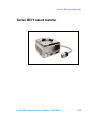 3
3
-
 4
4
-
 5
5
-
 6
6
-
 7
7
-
 8
8
-
 9
9
-
 10
10
-
 11
11
-
 12
12
-
 13
13
-
 14
14
-
 15
15
-
 16
16
-
 17
17
-
 18
18
-
 19
19
-
 20
20
-
 21
21
-
 22
22
-
 23
23
-
 24
24
-
 25
25
-
 26
26
-
 27
27
-
 28
28
-
 29
29
-
 30
30
-
 31
31
-
 32
32
-
 33
33
-
 34
34
-
 35
35
-
 36
36
-
 37
37
-
 38
38
-
 39
39
-
 40
40
-
 41
41
-
 42
42
-
 43
43
-
 44
44
-
 45
45
-
 46
46
-
 47
47
-
 48
48
-
 49
49
-
 50
50
-
 51
51
-
 52
52
-
 53
53
-
 54
54
-
 55
55
-
 56
56
-
 57
57
-
 58
58
-
 59
59
-
 60
60
-
 61
61
-
 62
62
-
 63
63
-
 64
64
-
 65
65
-
 66
66
-
 67
67
-
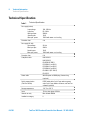 68
68
-
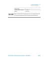 69
69
-
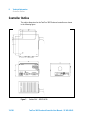 70
70
-
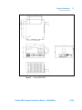 71
71
-
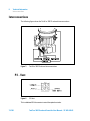 72
72
-
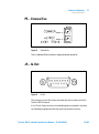 73
73
-
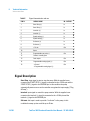 74
74
-
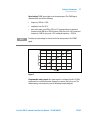 75
75
-
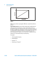 76
76
-
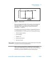 77
77
-
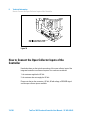 78
78
-
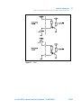 79
79
-
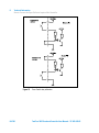 80
80
-
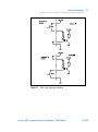 81
81
-
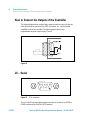 82
82
-
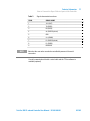 83
83
-
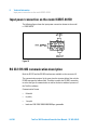 84
84
-
 85
85
-
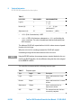 86
86
-
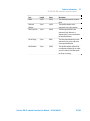 87
87
-
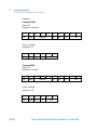 88
88
-
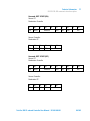 89
89
-
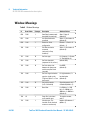 90
90
-
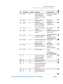 91
91
-
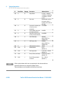 92
92
-
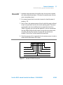 93
93
-
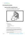 94
94
-
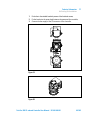 95
95
-
 96
96
-
 97
97
-
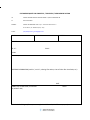 98
98
-
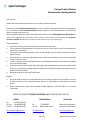 99
99
-
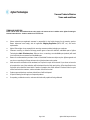 100
100
-
 101
101
-
 102
102


Agilent Technologies X3507-64131 Manual de usuario
- Tipo
- Manual de usuario
- Este manual también es adecuado para
En otros idiomas
Documentos relacionados
Otros documentos
-
Converters.TV 702 Manual de usuario
-
 Roger Technology BRUSHLESS KIT BG30/2204 Guía de instalación
-
DFI NB32-SL Manual de usuario
-
ASROCK 939N68PV-GLAN El manual del propietario
-
-
Dometic 7220 Guía de instalación
-
ASROCK ALIVENF7G-HD720P R2.0 El manual del propietario
-
ASROCK ALIVENF7G-HDREADY-2582 El manual del propietario
