Chauvin-Arnoux CA5231 El manual del propietario
- Categoría
- Multimetros
- Tipo
- El manual del propietario

25 - 117
C.A 5231
MULTIMÈTRE
MULTIMETER
MULTIMETER
MULTIMETRO
MULTIMETRO
FRAN
Ç
AIS
ENGLISH
DEUTSCH
ITALIANO
ESPAŇOL
Notice de fonctionnement
User’s manual
Bedienungsanleitung
Manuale d’uso
Manual
d
e instruccion
es

Français
2 - 117
PRÉCAUTIONS D’EMPLOI
Cet appareil est conforme à la norme de sécurité IEC 61010-1
(Ed 2 – 2001) pour des tensions de 1000 V en catégorie III ou
600 V en catégorie IV à une altitude inférieure à 2000 m et en
intérieur, avec un degré de pollution au plus égal à 2.
Le non-respect des consignes de sécurité peut entraîner un
risque de choc électrique, de feu, d'explosion, de destruction de
l'appareil et des installations.
N’utilisez pas l'appareil en atmosphère explosive ou en
présence de gaz ou fumées inflammables.
N’utilisez pas l'appareil sur des réseaux de tensions
ou de catégories supérieures à celles mentionnées.
Respectez les tensions et intensités maximales assignées
entre bornes et par rapport à la terre.
N’utilisez pas l'appareil s'il semble endommagé, incomplet ou
mal fermé.
Avant chaque utilisation, vérifiez le bon état des isolants des
cordons, boîtier et accessoires. Tout élément dont l'isolant
est détérioré (même partiellement) doit être consigné pour
réparation ou pour mise au rebut.
Utilisez des cordons et accessoires de tensions et de
catégories au moins égales à celles de l'appareil.
Respectez les conditions environnementales d'utilisation.
Ne modifiez pas l'appareil et ne remplacez pas des
composants par des équivalences. Les réparations ou les
ajustages doivent être effectués par du personnel compétent
agréé.
Remplacez la pile dès l'apparition du symbole sur
l'afficheur. Déconnectez tous les cordons avant ouverture de
la trappe d'accès à la pile.
Utilisez des protections individuelles de sécurité lorsque les
conditions l'exigent.
Ne gardez pas les mains à proximité des bornes non
utilisées de l'appareil.
Lors de la manipulation des sondes ou des pointes de
touche, ne placez pas les doigts au-delà de la garde
physique.

Français
3 - 117
CATÉGORIES DE MESURE
Définition des catégories de mesure selon la norme IEC 61010-1 :
CAT I : Circuits non reliés directement au réseau et spécialement
protégés.
Exemple: circuits électroniques protégés.
CAT II : Circuits directement branchés à l'installation basse tension.
Exemple : alimentation d’appareils électrodomestiques et d’outillage
portable.
CAT III : Circuits d’alimentation dans l'installation du bâtiment.
Exemple : tableau de distribution, disjoncteurs, machines ou
appareils industriels fixes.
CAT IV : Circuits source de l'installation basse tension du bâtiment.
Exemple : arrivées d’énergie, compteurs et dispositifs de protection.
English ......................................................................................... 25
Deutsch ........................................................................................ 48
Italiano .......................................................................................... 71
Español ........................................................................................ 94

Français
4 - 117
Vous venez d’acquérir un multimètre C.A 5231 et nous vous
remercions de votre confiance.
Pour obtenir le meilleur service de votre appareil :
Lisez attentivement cette notice de fonctionnement ;
Respectez les précautions d’emploi.
Signification des symboles utilisés sur l’appareil :
Risque de danger. L'opérateur s'engage à consulter la
présente notice à chaque fois que ce symbole de danger
est rencontré.
Pile 9 V.
Le marquage CE indique la conformité aux directives
européennes.
Isolation double ou isolation renforcée.
Tri sélectif des déchets pour le recyclage des matériels
électriques et électroniques au sein de l'Union
Européenne. Conformément à la directive DEEE
2002/96/EC :
ce matériel ne doit pas être traité comme déchet
ménager.
AC – Courant alternatif.
AC et DC – Courant alternatif et continu.
Terre.

Français
5 - 117
SOMMAIRE
1. PRÉSENTATION .......................................................................... 6
1.1 L’AFFICHEUR ................................................................................ 7
1.2 LES TOUCHES .............................................................................. 9
1.3 LE COMMUTATEUR ................................................................... 10
1.4 LES BORNES .............................................................................. 11
2. UTILISATION .............................................................................. 11
2.1 PREMIÈRE UTILISATION .......................................................... 11
2.2 MISE EN SERVICE DU MULTIMÈTRE ..................................... 12
2.3 ARRÊT DU MULTIMÈTRE ......................................................... 12
2.4 LA BÉQUILLE .............................................................................. 12
3. FONCTIONS................................................................................ 13
3.1 FONCTIONS DU COMMUTATEUR ........................................... 13
3.2 FONCTIONS DES TOUCHES .................................................... 16
4. CARACTÉRISTIQUES ................................................................ 17
4.1 CONDITIONS DE RÉFÉRENCE ................................................ 17
4.2 CARACTÉRISTIQUES AUX CONDITIONS DE RÉFÉRENCE 18
4.3 CONDITIONS D’ENVIRONNEMENT ......................................... 20
4.4 CARACTÉRISTIQUES CONSTRUCTIVES............................... 20
4.5 ALIMENTATION .......................................................................... 21
4.6 CONFORMITÉS AUX NORMES INTERNATIONALES ............ 21
4.7 VARIATIONS DANS LE DOMAINE D’UTILISATION................... 21
5. MAINTENANCE .......................................................................... 22
5.1 NETTOYAGE ............................................................................... 22
5.2 REMPLACEMENT DE LA PILE .................................................. 22
5.3 VÉRIFICATION MÉTROLOGIQUE ............................................ 22
5.4 RÉPARATION .............................................................................. 23
6. GARANTIE .................................................................................. 23
7. POUR COMMANDER ................................................................. 24

Français
6 - 117
1. PRÉSENTATION
Le C.A 5231 est un multimètre numérique TRMS, portatif et
autonome, spécialement conçu pour regrouper en un seul
appareil les différentes fonctions de mesure des grandeurs
électriques suivantes :
Voltmètre en courant alternatif à basse impédance d'entrée
(mesure de tensions en électricité et en électrotechnique) ;
Voltmètre en courant alternatif et/ou continu à haute
impédance d'entrée (mesure de tensions en électronique) ;
Ohmmètre ;
Test de continuité avec buzzer ;
Test de diode ;
Ampèremètre (mesure avec pince ampèremétrique);
Détection de présence de tension réseau sans
contact (fonction NCV présence de phase) .
Figure 1 : le multimètre C.A 5231
1
2
3
4
Zone de détection NCV

Français
7 - 117
Rep. Désignation Voir §
1 Afficheur 1.1
2 Touches de fonction 1.2
3 Commutateur 1.3
4 Bornes 1.4
1.1 L’AFFICHEUR
L’afficheur permet :
Un affichage de type analogique du paramètre mesuré grâce
au bargraphe, associé à l’affichage digital sur 6000 points.
Une lecture confortable des informations grâce au rétro-
éclairage de l’écran.
7 6 8 5
Figure 2 : l’afficheur
1
2
4
3

Français
8 - 117
Rep. Fonction Voir §
1 Bargraphe
2 Affichage (valeurs et unités de mesure) 3.1
3 Nature de la mesure (alternatif ou continu) 3.2.1
4 Mode automatique de sélection du calibre de
mesure (Autorange) 3.2.2
5 Indicateur de pile usagée 5.2
6 Test de continuité sonore
Test de diode 3.1.3
3.1.4
7 HOLD 1.2
8 Mode Non Permanent : arrêt automatique de
l’appareil activé 3.2.1
1.1.1 Les symboles de l’afficheur
L’afficheur utilise les symboles suivants :
Symboles Désignation
AC Courant alternatif
DC Courant continu
AUTO Changement automatique du calibre (voir § 1.1.3)
HOLD Mémorisation et affichage des valeurs mémorisées
O.L Dépassement des capacités de mesure (voir §1.1.2)
V Volt
A Ampère
ΩOhm
m Préfixe milli-
k Préfixe kilo-
M Préfixe méga-
Test de continuité sonore
Test de diode

Français
9 - 117
Mode Non Permanent (arrêt automatique activé)
Indicateur de pile usagée
1.1.2 Dépassement des capacités de mesure (O.L.)
Le symbole O.L. (Over Load) s’affiche quand le signal mesuré
dépasse les capacités du calibre de l’appareil.
1.1.3 Changement automatique du calibre de
mesure (Autorange)
Le symbole AUTO sur l’afficheur indique que l’appareil change
automatiquement le calibre de mesure pour effectuer la
mesure. Vous pouvez changer manuellement le calibre en
appuyant sur (voir § 3.2.2).
1.2 LES TOUCHES
Le clavier possède trois touches : , et . Voici les
touches du clavier.
1 2 3
Figure 3 : les touches du clavier
Rep. Fonction Voir §
1 Sélection du type de mesure (AC ou DC),
,
ou . Activation ou désactivation de l’arrêt
automatique de l’appareil au démarrage .
3.2.1
2 Sélection manuelle du calibre de mesure . 3.2.2
3 Maintien de l’affichage de la valeur mesurée .
Activation ou désactivation du rétro éclairage
bleu de l’écran ( ) (appui > 2s) 0

Français
10 - 117
1.3 LE COMMUTATEUR
Le commutateur possède sept positions. Les fonctions sont
décrites dans le tableau ci-dessous :
4
Figure 4 : le commutateur
Rep. Fonction Voir §
1 Mode OFF – Arrêt du multimètre 2.3
2 Mesure de tension alternative (AC) en basse
impédance (V
LowZ
) 3.1.1
3 Mesure de tension en AC ou DC (V) 3.1.1
4 Mesure de tension en AC ou DC (mV) 3.1.1
5 Mesure de résistance
Test de continuité
Test de diode
3.1.2
3.1.3
3.1.4
6 Mesure d’intensité avec pince AC ou DC, de
rapport 1mV/A 3.1.5
7 NCV (Non Contact Voltage) + Mode OFF
partiel du multimètre (fonction NCV active) 3.1.6
1
2
3 5
6
7

Français
11 - 117
1.4 LES BORNES
Les bornes sont utilisées comme suit :
1 2
Figure 5 : les bornes
Rep. Fonction
1 Borne point froid (COM)
2 Borne point chaud (+)
2. UTILISATION
2.1 PREMIÈRE UTILISATION
Placez la pile fournie avec l’appareil comme suit :
1. A l’aide d’un tournevis, dévissez les quatre vis a, b, c et d
de la trappe (rep.1) situées à l’arrière du boîtier ;
2. Placez la pile dans son logement (rep.2) en respectant les
polarités ;
3. Revissez la trappe au boîtier . Remettez en place la
béquille.
Figure 6 : accès à la pile
1 2
a b
c
d

Français
12 - 117
2.2 MISE EN SERVICE DU MULTIMÈTRE
Le commutateur est sur la position . Tournez le
commutateur vers la fonction de votre choix. L’ensemble des
segments de l’afficheur apparaît pendant quelques secondes
(voir figure 2, § 1.1) puis l’écran de la fonction choisie s’affiche.
Le multimètre est alors prêt pour les mesures.
2.3 ARRÊT DU MULTIMÈTRE
L’arrêt se fait soit de façon manuelle par retour du commutateur
en position , soit automatiquement après 15 minutes de
non-utilisation. A la 14
ème
minute, 5 bip préviennent de l’arrêt
imminent du multimètre. Pour réactiver l’appareil, appuyez sur
une touche du clavier.
Nota : la position n’arrête pas totalement le multimètre,
celui-ci reste actif pour la détection de présence de tension
réseau sans contact (NCV).
2.4 LA BÉQUILLE
Deux positions de béquille sont possibles, soit accrocher le
multimètre (position 1), soit le poser sur un support en position
inclinée (position 2). Pour changer la position de la béquille,
procédez comme suit :
Positon 1 : positionnez la
béquille vers le haut : Position 2 : positionnez la
béquille vers le bas :
Zone
d’accrochage
pour
accessoire de
fixation multi-
positions

Français
13 - 117
3. FONCTIONS
3.1 FONCTIONS DU COMMUTATEUR
Pour accéder aux fonctions du commutateur, placez le
commutateur sur , , , , , ou .
3.1.1 Mesure de tension
L’appareil mesure :
La tension alternative en basse impédance d’entrée (V
LOWZ
) ;
La tension continue (DC) ;
La tension alternative (AC).
Pour mesurer une tension, procédez comme suit :
1. Positionnez le commutateur sur , ou ; en
l’appareil est uniquement en mode AC ;
2. Pour ou ,sélectionnez AC ou DC en appuyant
sur . Par défaut, l’appareil est en mode DC . En
fonction de votre sélection, l’écran affiche DC ou AC ;
3. Branchez le cordon noir sur la borne COM et le cordon
rouge sur « + » ;
4. Placez les pointes de touche aux bornes du circuit à
mesurer ;
La valeur de la tension mesurée s’affiche à l’écran.
3.1.2 Mesure de résistance
Attention : toutes les mesures de résistance doivent se faire
hors tension.
Pour mesurer la résistance, procédez comme suit :
1. Positionnez le commutateur sur ;
2. Branchez le cordon noir sur la borne COM et le cordon
rouge sur « + » ;

Français
14 - 117
3. Placez les pointes de touche aux bornes du composant
ou du circuit à mesurer ;
La valeur de la résistance mesurée s’affiche à l’écran.
3.1.3 Test de continuité avec Buzzer
Attention : toutes les mesures de continuité doivent se faire
hors-tension.
Pour tester la continuité électrique, procédez comme suit :
1. Positionnez le commutateur sur ;
2. Appuyez sur . Le symbole s’affiche ;
3. Branchez le cordon noir sur la borne COM et le cordon
rouge sur « + ».
4. Placez les pointes de touche aux bornes du composant
ou du circuit à tester ;
Le signal sonore du buzzer indique la continuité et la valeur de
la résistance mesurée s’affiche à l’écran.
3.1.4 Test de diode
Attention : toutes les mesures de test diode doivent se faire
hors-tension.
Pour effectuer un test de diode, procédez comme suit :
1. Positionnez le commutateur sur ;
2. Appuyez deux fois sur . Le symbole s’affiche ;

Français
15 - 117
3. Branchez le cordon noir sur la borne COM et le cordon
rouge sur « + » ;
4. Placez les pointes de touche aux bornes du composant ;
La valeur de la tension développée s’affiche à l’écran.
3.1.5 Mesure d’intensité avec Pince
Ampèremétrique
1. Positionnez le commutateur sur ;
2. Sélectionnez AC ou DC en appuyant sur . Par défaut,
l’appareil est en mode AC. En fonction de votre sélection,
l’écran affiche DC ou AC ;
3. Branchez le cordon noir de la Pince sur la borne COM et
le cordon rouge de la Pince sur « + » ;
4. Enserrez la Pince sur le conducteur à mesurer ;
La valeur du courant mesuré s’affiche à l’écran.
Sens direct
Pince 1 mV DC/1 A DC ou
1 mV AC/1 A AC

Français
16 - 117
3.1.6 Non Contact Voltage NCV
1. Positionnez le commutateur sur ;
2. Approchez le C.A 5231 (zone de détection NCV) du (des)
conducteur(s) potentiellement sous tension (présence de
phase) ;
3. Si présence de tension réseau de 230V (modèle Europe),
le rétro-éclairage s’allume en rouge ; dans le cas
contraire, il reste éteint.
3.2 FONCTIONS DES TOUCHES
Les fonctions des touches , , sont accessibles par
appuis successifs courts ou long. Chaque appui est validé par
un signal sonore.
3.2.1 Touche
Cette touche permet de sélectionner la nature et le mode
d’affichage des mesures ainsi que de désactiver l’arrêt
automatique de l’appareil, au démarrage, en combinaison avec
le commutateur. Un appui maintenu lors du démarrage en
tournant le commutateur de vers n’importe quelle position
désactive l’arrêt automatique. Le symbole est affiché.
Remarque : le mode DC est activé par défaut.
Chaque appui… … permet
court
de changer la nature de la mesure
: AC
ou DC.
de sélectionner les modes test de
continuité ou test de diode .
3.2.2 Touche
Cette touche permet de choisir manuellement un calibre de
mesure. Le calibre définit l’étendue de mesure maximale que
l’appareil peut effectuer.
Remarque : le mode Auto-range est activé par défaut.

Français
17 - 117
Chaque appui … … permet
court de changer manuellement le calibre
de mesure (étendue et résolution).
long
(> 2 sec) de revenir en mode Auto-range.
Remarque : les modes test de continuité et test de diode
ne sont pas Auto-range.
3.2.3 Touche
Cette touche permet de maintenir l’affichage de la valeur
mesurée, ainsi que d’activer / désactiver le rétro-éclairage de
l’écran.
Chaque appui … … permet
court
de maintenir l’affichage de la
valeur mesurée ;
de sortir du mode .
long
(> 2 sec)
d’activer ou de désactiver le rétro-
éclairage de l’écran.
Nota : le rétro-éclairage s’éteint au
bout de 10 secondes .
4. CARACTÉRISTIQUES
4.1 CONDITIONS DE RÉFÉRENCE
Grandeurs d’influence Conditions de référence
Température : 23 °C ± 2 °C
Humidité relative : 45 % à 75 %
Tension d’alimentation : 8,5 V ± 0,5 V

Français
18 - 117
4.2 CARACTÉRISTIQUES AUX CONDITIONS DE
RÉFÉRENCE
L’incertitude est exprimée en x % de la lecture + y point(s), de
10% à 100% de chaque gamme de mesure.
4.2.1 Tensions continues
L’impédance d’entrée est de 10MΩ.
mV DC
Gamme Résolution Incertitude (±)
60 mV 0,01 mV 1 % + 12 pts
600 mV 0,1 mV 0,6 % + 2 pts
V DC
Gamme Résolution Incertitude (±)
600 mV 0,1 mV 0,6 % + 2 pts
6 V 0,001 V
0,2 % + 2 pts
60 V 0,01 V
600 V 0,1 V
1000 V 1 V
4.2.2 Tensions alternatives
L’impédance d’entrée est de 10 MΩ.
mV AC True RMS
Gamme Résolution Incertitude (±)
40 Hz à 60 Hz
Incertitude (±)
60 Hz à 1 kHz
60 mV 0,01 mV 1 % + 12 pts 1 % + 12 pts
2 % + 3 pts
600 mV 0,1 mV 1 % + 3 pts

Français
19 - 117
V AC True RMS
Gamme Résolution Incertitude (±)
40 Hz à 60 Hz Incertitude (±)
60 Hz à 1 kHz
6 V 0,001 V
1 % + 3 pts
2,5 % + 3 pts
60 V 0,01 V 2 % + 3 pts
600 V 0,1 V
1000 V 1 V 2 % + 3 pts 2,5 % + 3 pts
4.2.3 Tensions alternatives en basse impédance
(V AC LowZ True RMS)
L’impédance d’entrée est de 270kΩ.
Une basse impédance d’entrée permet de s’affranchir des
tensions parasites dues au réseau d’alimentation, et de
mesurer une tension alternative en minimisant les erreurs.
Gamme Résolution Incertitude (±)
6 V 0,001 V
40 Hz à 60 Hz
2 % + 1 pt
60 V 0,01 V
600 V 0,1 V
1000 V 1 V
4.2.4 Résistance
Gamme Résolution Incertitude
(±)
600 Ω 0,1 Ω 2 % + 2 pts
6k Ω 0,001 kΩ
0,3 % + 4 pts
60 kΩ 0,01 kΩ
600 kΩ 0,1 kΩ
6 MΩ 0,001 MΩ
60 MΩ 0,01 MΩ 0,5 % + 20 pts

Français
20 - 117
4.2.5 Test de continuité
Gamme Résolution Incertitude Courant
de mesure
600 Ω 0,1 ΩSignal sonore
déclenché 50 Ω
± 10 Ω< 0,35 mA
4.2.6 Test de diode
Gamme Résolution Incertitude
(±) Tension en
circuit ouvert Courant
de mesure
2,8 V 0,001 V 1 % + 2 pts < 2,8 V < 0,9 mA
4.2.7 Courants alternatifs / continus
600 A AC ou DC avec pince ratio 1 mV / 1 A
Gamme Résolution Incertitude (±)
600 A 0,1 A 40 Hz à 1 kHz
2,0 % + 2 pts
(note 1)
Note 1 : hors incertitude liée au capteur pince de courant.
4.3 CONDITIONS D’ENVIRONNEMENT
Conditions d’environnement en utilisation en stockage
Température : 0 °C à +50 °C -20 °C à +70 °C
Humidité relative (HR) : <=90 % à
40 °C <=50 % à 60 °C
4.4 CARACTÉRISTIQUES CONSTRUCTIVES
Dimension : H 155 x L 75 x P 55 mm
Masse : 320 g (avec la pile)
Acquisition
mesure : 3 fois par seconde
Bargraphe : 61 segments, vitesse de rafraîchissement 30ms

Français
21 - 117
4.5 ALIMENTATION
Alimentation : Pile 9 V LF22/6LR61
Autonomie : > 100 heures à température ambiante
Délai d’auto extinction : Après 15 minutes de non utilisation
4.6 CONFORMITÉS AUX NORMES
INTERNATIONALES
Sécurité électrique : Application des règles de sécurité selon la
norme EN 61010-1-Ed.2 : 2001.
1000V CAT III - 600V CAT IV. Degré de
pollution 2. Double isolation.
Compatibilité
électromagnétique : Conforme à la norme EN 61326/A2 : 2001
Milieu résidentiel
Résistance
mécanique : Chute libre : 1 m (selon la norme
IEC 68-2-32)
Degré de protection
de l'enveloppe : IP54 selon EN 60529
4.7 VARIATIONS DANS LE DOMAINE D’UTILISATION
Grandeur d’influence Plage d’influence Influence
Température 0°C à + 50°C
V AC : 0,5%L/10°C
mV DC : 0,5%L/10°C
Ω (R>20 MΩ) :
0,5%L/10°C
Fréquence 1 à 3 kHz
V AC : 10%L + 1pt

Français
22 - 117
5. MAINTENANCE
Pour la maintenance, utilisez seulement les pièces de rechange
qui ont été spécifiées.
5.1 NETTOYAGE
Déconnectez tout cordon de l’appareil et positionnez le
commutateur sur .
Utilisez un chiffon doux, légèrement imbibé d’eau
savonneuse. Rincez avec un chiffon humide.
Séchez parfaitement avec un chiffon sec ou de l’air pulsé
avant toute nouvelle utilisation.
5.2 REMPLACEMENT DE LA PILE
Le symbole indique que la pile est usée et qu’elle doit être
changée. Quand ce symbole apparaît sur l’afficheur, l’appareil
fonctionne encore quelques minutes puis il s’éteint.
Pour remplacer la pile, procédez comme suit :
1. Positionnez le commutateur sur ;
2. Déconnectez les cordons de mesure des bornes
d’entrées ;
3. A l’aide d’un tournevis, dévissez les quatre vis de la
trappe d’accès à la piles située à l’arrière du boîtier (voir §
2.1) ;
4. Remplacez la pile défectueuse (voir § 2.1) ;
5. Revissez la trappe au boîtier. Remettez en place la
béquille.
5.3 VÉRIFICATION MÉTROLOGIQUE
Comme tous les appareils de mesure ou d’essai, une
vérification périodique est nécessaire.
Nous vous conseillons une vérification annuelle de cet appareil.
Pour les vérifications et étalonnages, adressez-vous à nos
laboratoires de métrologie accrédités COFRAC ou aux centres
techniques MANUMESURE.
Renseignements et coordonnées sur demande :
Tél. : 02 31 64 51 43 Fax : 02 31 64 51 09

Français
23 - 117
5.4 RÉPARATION
Pour les réparations sous garantie et hors garantie, contactez
votre agence commerciale CHAUVIN-ARNOUX la plus proche
ou votre centre technique régional Manumesure, qui établira un
dossier de retour et vous communiquera la procédure à suivre.
Coordonnées disponibles sur notre site : http://www.chauvin-
arnoux.com ou par téléphone aux numéros suivants : 02 31 64
51 43 (centre technique Manumesure), 01 44 85 44 85
(Chauvin-Arnoux).
Pour les réparations hors de France métropolitaine, sous
garantie et hors garantie, retournez l’appareil à votre agence
Chauvin-Arnoux locale ou à votre distributeur.
6. GARANTIE
Notre garantie s’exerce, sauf stipulation expresse, pendant
douze mois après la date de mise à disposition du matériel.
Extrait de nos Conditions Générales de Vente, communiquées
sur demande.
La garantie ne s’applique pas suite à :
Une utilisation inappropriée de l’équipement ou à une
utilisation avec un matériel incompatible ;
Des modifications apportées à l’équipement sans
l’autorisation explicite du service technique du fabricant ;
Des travaux effectués sur l’appareil par une personne non
agréée par le fabricant ;
Une adaptation à une application particulière, non prévue par
la définition du matériel ou non indiquée dans la notice
fonctionnement ;
Des dommages dus à des chocs, chutes ou inondations.

Français
24 - 117
7. POUR COMMANDER
Le C.A 5231
Le multimètre est livré avec :
• 1 paire de cordons pointe de touche, rouge et noir
• 1 pile 9 V alcaline
• la notice de fonctionnement 5 langues.
C.A 5231 P01196731
Accessoires
Pince MINI 03 (1 A - 100 A AC) P01105103Z
Pince MN 15 (0,5 A - 240 A AC P01120417
Miniflex MA 100 (2000 A) * P01120501
Pince PAC 10 (1 A – 400 A AC/600 A DC) P01120070
Pince C107 (0,1 A – 1200 A AC) * P01120305
C.A 5231 avec MINI 03 P01196734Z
Nota * : mesure limitée à 600 A AC

English
25 - 117
PRECAUTIONS FOR USE
This device complies with safety standard IEC-61010-1
(Ed 2–2001) for voltages up to 1000V in category III or 600V in
category IV, at an altitude below 2000m, indoors, with a
pollution level of not more than 2.
Failure to observe the safety instructions may cause an electric
shock, fire, explosion, or destruction of the instrument and of
the installations.
Do not use the instrument in an explosive atmosphere or in
the presence of flammable gases or fumes.
Do not use the instrument on networks of which the voltage
or category exceeds those mentioned.
Do not exceed the rated maximum voltages and currents
between terminals or with respect to earth.
Do not use the instrument if it appears to be damaged,
incomplete, or not properly closed.
Before each use, check the condition of the insulation on the
leads, housing, and accessories. Any element of which the
insulation is deteriorated (even partially) must be set aside
for repair or scrapped.
Use leads and accessories rated for voltages and categories
at least equal to those of the instrument.
Observe the environmental conditions of use.
Do not modify the instrument and do not replace components
with "equivalents". Repairs and adjustments must be done by
approved qualified personnel.
Replace the battery as soon as the symbol appears on the
display unit. Disconnect all leads before opening the battery
compartment cover.
Use personal protective equipment when conditions require.
Keep your hands away from the unused terminals of the
instrument.
When handling probes or contact tips, keep your fingers
behind the guards.

English
26 - 117
MEASUREMENT CATEGORIES
Definitions of the measurement categories according to standard IEC
61010-1:
CAT I: Circuits not directly connected to the network and specially
protected.
Example: protected electronic circuits.
CAT II: Circuits directly connected to the low-voltage installation.
Example: power supply to household electrical appliances and
portable tools.
CAT III: Power supply circuits in the installation of the building.
Example: distribution panel, circuit-breakers, fixed industrial
machines or devices.
CAT IV: Circuits supplying the low-voltage installation of the building.
Example: power lines, meters, and protection devices.
Français ....................................................................................... 2
Deutsch ........................................................................................ 48
Italiano .......................................................................................... 71
Español ........................................................................................ 94

English
27 - 117
Thank you for purchasing a C.A. 5231 multimeter.
For best results from your device:
Read this user manual attentively;
Observe the precautions for its use.
Meaning of symbols used on the instrument :
Risk of danger. The operator agrees to refer to these
instructions whenever this danger symbol appears.
9 V Battery.
The CE marking indicates compliance with European
directives.
Double or reinforced insulation.
Selective sorting of wastes for the recycling of electrical
and electronic equipment within the European Union.In
conformity with directive DEEE 2002/96/EC: this
equipment must not be treated as household waste.
AC – Alternating current.
AC or DC – Alternating or direct current.
Earth.

English
28 - 117
CONTENTS
1. PRESENTATION ........................................................................ 29
1.1 DISPLAY UNIT ............................................................................. 30
1.2 THE KEYS .................................................................................... 32
1.3 THE SWITCH ............................................................................... 33
1.4 THE TERMINALS ........................................................................ 34
2. USE 34
2.1 FIRST USE ................................................................................... 34
2.2 POWERING UP THE MULTIMETER ......................................... 35
2.3 POWERING DOWN THE MULTIMETER .................................. 35
2.4 THE PROP ................................................................................... 35
3. FUNCTIONS ................................................................................ 36
3.1 FUNCTIONS OF THE SWITCH.................................................. 36
3.2 FUNCTIONS OF THE KEYS ...................................................... 39
4. CHARACTERISTICS .................................................................. 40
4.1 REFERENCE CONDITIONS ...................................................... 40
4.2 CHARACTERISTICS AT THE REFERENCE CONDITIONS ... 41
4.3 ENVIRONMENTAL CONDITIONS ............................................. 43
4.4 CHARACTERISTICS OF CONSTRUCTION ............................. 43
4.5 POWER SUPLLY......................................................................... 44
4.6 COMPLIANCE WITH INTERNATIONAL STANDARDS ........... 44
4.7 VARIATIONS IN DOMAIN OF USE ............................................. 44
5. MAINTENANCE .......................................................................... 45
5.1 CLEANING ................................................................................... 45
5.2 REPLACING THE BATTERY ..................................................... 45
5.3 METROLOGICAL CHECK .......................................................... 45
5.4 REPAIR ........................................................................................ 45
6. WARRANTY ................................................................................ 46
7. TO ORDER .................................................................................. 47

English
29 - 117
1. PRESENTATION
The C.A 5231 is a TRMS digital multimeter, specially designed
to combine in a single instrument the various functions and
measurements of the following electrical quantities:
AC voltmeter with low input impedance (voltage
measurements in the fields of electricity and electrical
engineering);
AC and/or DC voltmeter with high input impedance (voltage
measurements in the field of electronics);
Ohmmeter;
Continuity test with buzzer;
Diode test;
Ammeter (measurement by clamp-on ammeter);
Contact-free detection of presence of network voltage (NCV
function, presence of phase).
Figure 1 : the C.A 5231 multimeter
1
2
3
4
NCV detection zone

English
30 - 117
Item Designation See §
1 Display unit 1.1
2 Function keys 1.2
3 Switch 1.3
4 Terminals 1.4
1.1 DISPLAY UNIT
The display unit allows :
An analog display of the parameter measured, in the form of
a bargraph, associated with a 6,000-point digital display.
Comfortable reading of the information thanks to the
backlighting of the screen.
7 6 8 5
Figure 2 : display unit
1
2
4
3

English
31 - 117
Item Function See §
1 Bargraph
2 Display (values and units of measurement) 3.1
3 Nature of measurement (AC or DC) 3.2.1
4 Automatic measurement range selection
mode (Autorange) 3.2.2
5 Low battery indicator 5.2
6 Audible continuity test
Diode test 3.1.3
3.1.4
7 HOLD 1.2
8 Non-Permanent Mode : automatic switching
off of the device activated 3.2.1
1.1.1 The symbols on the display unit
The display unit uses the following symbols :
Symbol Designation
AC Alternating current
DC Direct current
AUTO Automatic change of range (see § 1.1.3)
HOLD Storage and display of stored values
O.L Overshoot of measurement capabilities (see §1.1.2)
V Volt
A Ampere
ΩOhm
m Prefix milli-
k Prefix kilo-
M Prefix Mega-
Audible continuity test
Diode test

English
32 - 117
Mode Non Permanent
(automatic switching off
activated)
Low battery indicator
1.1.2 Overshoot of measurement capabilities (O.L.)
The O.L. (Over Load) symbol is displayed when the signal
measured exceeds the range of the device.
1.1.3 Automatic change of measurement range
(Autorange)
The AUTO symbol on the display unit indicates that the
instrument automatically changes the measurement range to
make the measurement. You can change the range manually
by pressing (see § 3.2.2).
1.2 THE KEYS
The keypad has three keys : , and . Here are the
keys of the keypad.
1 2 3
Figure 3 : the keys on the keypad
Item Function See §
1 Selection of the type of measurement (AC or
DC), ,
or . Activation or de-activation of the
automatic switching of the device at start-up.
3.2.1
2 Manual selection of the measurement range. 3.2.2
3 Hold of display of the measured value.
Activation or de-activation of the blue back-
lighting of the screen ( ) (press > 2s) 0

English
33 - 117
1.3 THE SWITCH
The switch has seven positions. The functions are described in
the table below :
4
Figure 4 : the switch
Item Function See §
1 OFF mode – Powers down the multimeter 2.3
2 Low-impedance AC voltage measurement
(V
LowZ
) 3.1.1
3 AC or DC voltage measurement (V) 3.1.1
4 AC or DC voltage measurement (mV) 3.1.1
5 Resistance measurement
Continuity test
Diode test
3.1.2
3.1.3
3.1.4
6 Current measurement with AC or DC clamp,
ratio 1mV/A 3.1.5
7 NCV (Non Contact Voltage) + Partial OFF
mode of the multimeter (NCV function active) 3.1.6
1
2
3 5
6
7

English
34 - 117
1.4 THE TERMINALS
The terminals are used as follows :
1 2
Figure 5 : the terminals
Item Function
1 Cold point terminal (COM)
2 Hot point terminal (+)
2. USE
2.1 FIRST USE
Insert the battery provided with the instrument as folows :
1. Using a screwdriver, unscrew the four screws (a, b, c, and
d) holding the cover (item 1) on the back of the housing;
2. Place the battery in its compartment (item 2); watch out
for the polarity;
3. Screw the cover back onto the housing. Put the stand
back in place.
Figure 6 : access to the battery
1 2
a b
c
d

English
35 - 117
2.2 POWERING UP THE MULTIMETER
The switch is set to . Turn the switch to the function of your
choice. All segments of the display unit light for a few seconds
(see Figure 2, § 1.1) the screen corresponding to the chosen
function then appears. The multimeter is now ready for
measurements.
2.3 POWERING DOWN THE MULTIMETER
The multimeter can be switched off manually, by setting the
switch to , it will also switch itself off automatically if left
unused for 15 minutes. At the 14th minute, 5 beeps warn that
the multimeter is about to be switched off. To reactivate the
instrument, press any key on the keypad.
Note : the position does not completely switch off the
multimeter; it remains active for contact-free detection of the
presence of the network voltage (NCV).
2.4 THE PROP
The prop can be placed in either of two positions according to
how it is to be used: to suspend the multimeter from a hook
(position 1) or to stand it in an inclined position on a support
(position 2). To change the position of the prop, proceed as
follows:
Positon 1 : raise the stand Position 2 : lower the stand
Hooking
zone for
multi-position
attachment
accessory

English
36 - 117
3. FUNCTIONS
3.1 FUNCTIONS OF THE SWITCH
To access to the functions of the switch, set the switch to
, , , , , or .
3.1.1 Voltage measurment
The instrument measures :
The AC voltage at low input impedance (V
LOWZ
) ;
Direct voltages (DC) ;
Alternating voltages (AC).
To measure a voltage, proceed as follows :
1. Set the switch to , or ; when set to the
device is in AC mode only.
2. For or ,select AC or DC by pressing . As
default, the device is in DC mode. Depending on your
selection, the screen displays AC or DC.
3. Connect the black lead to the COM terminal and the red
lead to « + » ;
4. Place the contact tips on the terminals of the circuit to be
measured ;
The measured voltage is displayed on screen.
3.1.2 Resistance measurement
Attention : all resistance measurements must be made in the
absence of any voltage.
To measure a resistance, proceed as follows :
1. Set the switch to ;
2. Connect the black lead to the COM terminal and the red
lead to « + » ;

English
37 - 117
3. Place the contact tips on the terminals of the component
or circuit to be measured ;
The measured resistance is displayed on screen.
3.1.3 Continuity test with buzzer
Attention : all continuity measurements must be made in the
absence of any voltage
To test electrical continuity, proceed as follows :
1. Set the switch to ;
2. Press . The symbol is displayed ;
3. Connect the black lead to the COM terminal and the red
lead to « + ».
4. Place the contact tips on the terminals of the component
or circuit to be tested ;
The buzzer indicates continuity ; the measured resistance is
displayed on screen.
3.1.4 Diode test
Attention : all diode test measurements must be made in a
power-off condition.
To test a diode, proceed as follows :
1. Set the switch to ;
2. Press twice. The symbol is displayed ;

English
38 - 117
3. Connect the black lead to the COM terminal and the red
lead to « + » ;
4. Place the contact tips on the terminals of the component ;
The voltage across the terminals of the component is displayed
on screen.
3.1.5 Current measurement using a Clamp-on
Ammeter
1. Set the switch to ;
2. Select AC or DC by pressing . As default, the device
is in AC mode. According to your selection, the screen
displays DC or AC ;
3. Connect the black lead of the Clamp to the COM terminal
and the red lead of the Clamp to « + » ;
4. Place the clamp on the conductor to be measured ;
The measured current is displayed on screen ;
Forward direction
1 mV DC/1 A DC or 1 mV
AC/1 A AC clamp

English
39 - 117
3.1.6 Non Contact Voltage NCV
1. Set the switch to ;
2. Move the C.A 5231 (NCV detection zone) close to the
potentially live conductor(s) (presence of phase) ;
3. If a network voltage of 230V is present (Europe model),
the back-lighting lights red, otherwise, it remains off.
3.2 FUNCTIONS OF THE KEYS
The functions of the , , keys can be accessed by
successive short or long presses. Each press is confirmed by
an audible signal.
3.2.1 The key
This key is used to select the type of measurement and the
display mode and to deactivate the automatic switching off of
the device, at start-up, in combination with the switch. A long
press during start-up, while turning the switch to any
position, deactivates automatic switching off. The symbol is
not displayed. As default, automatic switching off is activated
and the symbol is displayed.
Remark : the DC mode is activated as default.
Each press of
this length… … serves to
short
Change the nature of the
measurement : AC or DC.
Select the continuity test
or diode
test mode.
3.2.2 The key
This key is used to choose a measurement range manually.
The range defines the maximum measurement span of which
the device is capable.
Remark : the Auto-range mode is activated as default.

English
40 - 117
Each press of
this length … … serves to
short to change the measurement range
manually (span and resolution).
long
(> 2 sec) to return to Auto-range mode.
Remark : the continuity test and diode test modes are
not Auto-range;
3.2.3 The key
This key is used to hold the display of the measured value, and
to activate/deactivate the backlighting of the screen.
Each press of
this length … … serves to
short
To hold the display of the
measured value ;
To exit from the mode.
long
(> 2 sec)
To activate / deactivate the
backlighting of the screen.
Note : the backlighting is switched
off at the end of 10 seconds .
4. CHARACTERISTICS
4.1 REFERENCE CONDITIONS
Quantities of influence Reference conditions
Temperature : 23 °C ± 2 °C
Relative humidity: 45 % to 75 %
Supply voltage : 8,5 V ± 0,5 V

English
41 - 117
4.2 CHARACTERISTICS AT THE REFERENCE
CONDITIONS
The uncertainty is expressed in the form x% of the reading + y
counts, from 10% to 100% of each measurement range.
4.2.1 Direct voltages
The input impredance is 10MΩ.
mV DC
Range Resolution Uncertainty (±)
60 mV 0,01 mV 1 % + 12 cts
600 mV 0,1 mV 0,6 % + 2 cts
V DC
Range Resolution Uncertainty (±)
600 mV 0,1 mV 0,6 % + 2 cts
6 V 0,001 V
0,2 % + 2 cts
60 V 0,01 V
600 V 0,1 V
1000 V 1 V
4.2.2 Alternating voltages
The input impedance is 10 MΩ.
mV AC True RMS
Range Resolution Uncertainty (±)
40 Hz to 60 Hz
Uncertainty (±)
60 Hz to 1 kHz
60 mV 0,01 mV 1 % + 12 cts 1 % + 12 cts
2 % + 3 cts
600 mV 0,1 mV 1 % + 3 cts

English
42 - 117
V AC True RMS
Range Resolution Uncertainty (±)
40 Hz à 60 Hz Uncertainty (±)
60 Hz to 1 kHz
6 V 0,001 V
1 % + 3 cts
2,5 % + 3 cts
60 V 0,01 V 2 % + 3 cts
600 V 0,1 V
1000 V 1 V 2 % + 3 cts 2,5 % + 3 cts
4.2.3 Alternating voltages at low impedance(V
AC LowZ True RMS)
The input impedance is 270kΩ.
A low input impedance serves to eliminate the effects of
interference voltages due to the supply network, and makes it
possible to measure an AC voltage with a minimum of error.
Range Resolution Uncertainty (±)
6 V 0,001 V
40 Hz to 60 Hz
2 % + 1 ct
60 V 0,01 V
600 V 0,1 V
1000 V 1 V
4.2.4 Resistance
Range Resolution Uncertainty
(±)
600 Ω 0,1 Ω 2 % + 2 cts
6k Ω 0,001 kΩ
0,3 % + 4 cts
60 kΩ 0,01 kΩ
600 kΩ 0,1 kΩ
6 MΩ 0,001 MΩ
60 MΩ 0,01 MΩ 0,5 % + 20 cts

English
43 - 117
4.2.5 Continuity test
Range Resolution Uncertainty Measurement
current
600 Ω 0,1 ΩAudible signal
triggered 50 Ω
± 10 Ω< 0,35 mA
4.2.6 Diode test
Range Resolution Uncertainty
(±) Open-circuit
voltages Measurement
current
2,8 V 0,001 V 1 % + 2 cts < 2,8 V < 0,9 mA
4.2.7 AC/DC Current
600 A AC or DC with clamp having a ratio of 1 mV / 1 A
Range Resolution Uncertainty (±)
600 A 0,1 A 40 Hz to 1 kHz
2,0 % + 2 cts
(note 1)
Note 1 : not including the uncertainty due to the current clamp
sensor
4.3 ENVIRONMENTAL CONDITIONS
Environmental conditions In use In storage
Temperature : 0 °C to +50 °C -20 °C to +70 °C
Relative humidity (HR) : <=90% at 40°C <=50 % at 60 °C
4.4 CHARACTERISTICS OF CONSTRUCTION
Dimension : H 155 x L 75 x P 55 mm
Weight : 320 g (with the battery)
Measurement
acquisition : 3 times per second
Bargraph : 61 segments, refresh interval 30ms

English
44 - 117
4.5 POWER SUPLLY
Power supply : Pile 9 V LF22/6LR61
Battery life : > 100 heures à température ambiante
Automatic switching-
off
time : 15 minutes of non-use
4.6 COMPLIANCE WITH INTERNATIONAL
STANDARDS
Electrical safety :
Application of safety rules as per standard
EN-61010-1-Ed.2:2001.1000V CAT-III -
600V CAT-IV. Pollution level 2. Double
insulation.
Electromagnetic
compatibility : Compliant with standard EN-
61326/A2:2001Residential environment
Mechanical
strength : Free fall: 1m (in accordance with
standardIEC-68-2-32)
Degree of protection
of the housing : IP54 as per EN 60529
4.7 VARIATIONS IN DOMAIN OF USE
Quantity of influence Range of influence Influence
Temperature 0°C to + 50°C
V AC : 0,5%L/10°C
mV DC : 0,5%L/10°C
Ω (R>20 MΩ) :
0,5%L/10°C
µF (C>50µF)
5%L/10°C
Frequency 1 to 3 kHz
V AC : 10%L + 1ct

English
45 - 117
5. MAINTENANCE
For maintenance, use only the replacement parts specified.
5.1 CLEANING
Disconnectall leads from the instrument and set the switch to
.
Use a soft cloth, dampened with soapy water. Rinse with a
damp cloth.
Dry thoroughly with a dry cloth or forced air before using
again.
5.2 REPLACING THE BATTERY
The symbol indicates that the battery is low and must be
changed. When this symbol appears on the display unit, the
instrument continues to operate for a few minutes, then
switches itself off.
Pour remplacer la pile, procédez comme suit :
1. Set the switch to ;
2. Disconnect the measurement leads from the input
terminals;
3. Using a screwdriver, unscrew the four screws of the
battery compartment cover on the back of the housing
(see §2.1) ;
4. Replace the old battery (see § 2.1) ;
5. Screw the cover back onto the housing. Put the stand
back in place.
5.3 METROLOGICAL CHECK
Like all measuring or testing devices, the instrument must be
checked regularly.
This instrument should be checked at least once a year. For
checks and calibrations, contact one of our accredited
metrology laboratories (information and contact details available
on request), at our Chauvin Arnoux subsidiary or the branch in
your country.
5.4 REPAIR
For all repairs before or after expiry of warranty, please return
the device to your distributor.

English
46 - 117
6. WARRANTY
Except as otherwise stated, our warranty is valid for twelve
months starting from the date on which the equipment was sold.
Extract from our General Conditions of Sale provided on
request.
The warranty does not apply in the following cases:
Inappropriate use of the equipment or use with incompatible
equipment;
Modifications made to the equipment without the explicit
permission of the manufacturer’s technical staff;
Work done on the device by a person not approved by the
manufacturer;
Adaptation to a particular application not anticipated in the
definition of the equipment or not indicated in the user’s
manual;
Damage caused by shocks, falls, or floods.

English
47 - 117
7. TO ORDER
The C.A 5231
The multimeter is delivered with
• 1 pair of leads, red and black
• 1 9 V alkaline battery
• the user manual in 5 languages
C.A 5231 P01196731
Accessories
MINI 03 clamp (1 A - 100 A AC) P01105103Z
MN 15 clamp(0,5 A - 240 A AC P01120417
Miniflex MA 100 (2000 A) * P01120501
PAC 10 clamp (1 A – 400 A AC/600 A DC) P01120070
C107 clamp (0,1 A – 1200 A AC) * P01120305
C.A 5231 with MINI 03 P01196734Z
Note * : measurement limited to 600 A AC

Deutsch
48 - 117
BEDIENUNGSHINWEISE
Die Spannungs- und Überspannungskategorien dieses Geräts
[1000 V Messkategorie III, 600 V Messkategorie IV]
entsprechen der Sicherheitsnorm IEC 61010-1 (Ed 2 - 2001)
bzw. in Innenräumen, bis zu einem Verschmutzungsgrad 2 und
auf bis zu 2000 m Höhe.
Die Sicherheitsanweisungen müssen unbedingt beachtet
werden, weil sonst Stoßspannung, Brand, Explosion oder
Zerstörung des Geräts und der Anlagen drohen.
Das Gerät darf nicht in explosibler Atmosphäre verwendet
werden, wo brennbare Stoffe in Form von Gasen und
Dämpfen vorhanden sind.
Verwenden Sie das Gerät niemals in höherwertigen
Spannungsnetzen und Überspannungskategorien als
angegeben!
Halten Sie sich an die max. zul. Nennspannungen und -
ströme zwischen den Buchsen und gegen Erde.
Benutzen Sie niemals ein Gerät, das beschädigt,
unvollständig oder schlecht geschlossen erscheint.
Prüfen Sie vor jedem Einsatz nach, ob die Isolierung der
Drähte, des Gehäuses und des Zubehörs einwandfrei ist.
Teile mit selbst teilweise beschädigten Isolierungen müssen
repariert oder entsorgt werden.
Verwenden Sie nur Drähte und Zubehör, das mindestens
den angegebenen Spannungen und
Überspannungskategorien des Geräts entspricht.
Achten Sie auf die Umweltdaten für den Gerätebetrieb.
Das Gerät darf nicht geändert und die einzelnen
Komponenten dürfen nicht durch Gleichartige ersetzt
werden. Reparatur- und Einstellarbeiten am Gerät dürfen nur
von befugten Fachleuten vorgenommen werden.
Die Batterien müssen sofort ausgetauscht werden, wenn das
Symbol " " aufleuchtet. Alle Leitungen abnehmen, bevor
man das Batteriefach öffnet.
Tragen Sie je nach Arbeitsbedingungen nötigenfalls
geeignete Schutzkleidung.
Die Hände müssen in möglichst großer Entfernung von den
unbesetzten Gerätebuchsen gehalten werden.
Die Hände müssen beim Umgang mit Sonden bzw.
Prüfspitzen immer hinter der Schutzvorkehrung liegen.

Deutsch
49 - 117
MESSKATEGORIE
Definition der Messkategorien gemäß IEC 61010-1:
CAT I: Stromkreise, die nicht direkt mit dem Stromnetz verbunden
sind oder geschützt sind.
Beispiel: geschützte Stromkreise.
CAT II: Stromkreise an Niederspannungsanlagen.
Beispiel: Stromversorgung von Haushaltsgeräten oder
tragbaren Elektrowerkzeugen.
CAT III: Stromversorgungskreise innerhalb der Haus- oder
Gebäudeinstallation.
Beispiel: Verteiler, Leistungsschalter, fest installierte Maschinen
oder Industrieanlagen.
CAT IV: An der Quelle der Niederspannungsinstallation im Gebäude.
Beispiel: Hauptverteilung, Zähler und primärer
Überspannungsschutz.
Français ....................................................................................... 2
English ......................................................................................... 25
Italiano .......................................................................................... 71
Español ........................................................................................ 94

Deutsch
50 - 117
Sie haben ein C.A. 5231 Multimeter erstanden, wir danken
Ihnen für Ihr Vertrauen.
Für die Erlangung eines optimalen Betriebsverhaltens Ihres
Gerätes:
Lesen Sie bitte diese Betriebsanleitung aufmerksam durch
und;
Beachten Sie bitte die Anwendungshinweise.
Bedeutung der Gerätesymbole:
Gefahr! Sobald dieses Gefahrenzeichen auftritt, ist der
Bediener verpflichtet, die Anleitung zu Rate zu ziehen.
Batterie 9 V.
Die CE-Markierung bedeutet, dass das Gerät
anwendbaren europäischen Richtlinien erfüllt.
Das Gerät ist schutzisoliert bzw. durch eine verstärkte
Isolierung geschützt.
Der durchgestrichene Mülleimer bedeutet, dass das
Produkt in der Europäischen Union gemäß der Richtlinie
WEEE 2002/96/EC einer Abfalltrennung zur
Wiederaufbereitung von Elektro- und Elektronik-
Altgeräten unterzogen werden muss.
AC – Wechselstrom.
AC oder DC – Wechselstrom oder Gleichstrom.
Erde.

Deutsch
51 - 117
INHALT
1. VORSTELLUNG ......................................................................... 52
1.1 ANZEIGE ...................................................................................... 53
1.2 TASTEN ....................................................................................... 55
1.3 SCHALTER .................................................................................. 56
1.4 BUCHSEN .................................................................................... 57
2. VERWENDUNG .......................................................................... 57
2.1 ERSTE SCHRITTE ...................................................................... 57
2.2 MULTIMETER-INBETRIEBNAHME ........................................... 58
2.3 MULTIMETER ABSCHALTEN.................................................... 58
2.4 DER STANDBÜGEL .................................................................... 58
3. FUNKTIONEN ............................................................................. 59
3.1 DREHSCHALTERFUNKTIONEN ............................................... 59
3.2 TASTENFUNKTIONEN ............................................................... 62
4. EIGENSCHAFTEN ...................................................................... 63
4.1 REFERENZBEDINGUNGEN ...................................................... 63
4.2 EIGENSCHAFTEN ZU DEN REFERENZBEDINGUNGEN ...... 64
4.3 UMWELTBEDINGUNGEN .......................................................... 66
4.4 ALLGEMEINE BAUDATEN ......................................................... 66
4.5 STROMVERSORGUNG ............................................................. 67
4.6 KONFORMITÄT MIT INTERNATIONALEN NORMEN ............. 67
4.7 SCHWANKUNGEN IM EINSATZBEREICH ................................ 67
5. WARTUNG .................................................................................. 68
5.1 REINIGUNG ................................................................................. 68
5.2 BATTERIEWECHSEL ................................................................. 68
5.3 MESSTECHNISCHE ÜBERPRÜFUNG ..................................... 68
5.4 REPARATUR ............................................................................... 69
6. GARANTIE .................................................................................. 69
7. BESTELLANGABEN .................................................................. 70

Deutsch
52 - 117
1. VORSTELLUNG
Das C.A. 5231 ist ein TRMS Digital-Multimeter, das als
Mehrzweckgerät verschiedene Funktionen und Messungen für
folgende elektrische Größen bietet:
AC-Voltmeter für niedrige Eingangsimpedanz
(Spannungsmessen in Elektrik und Elektrotechnik);
AC- und/oder DC-Voltmeter bei hoher Eingangsimpedanz
(Spannungsmessen in Elektronik);
Ohmmeter;
Durchgangsprüfung mit Summer;
Diodenprüfung;
Amperemeter (Messung mit Strommesszange);
Berührungsfreie Erfassung von Netzspannung (NCV-
Funktion Vorhandsein von Phasen).
Abb. 1 : Multimeter C.A 5231
1
2
3
4
NCV-Schwellzone

Deutsch
53 - 117
Nr. Bezeichnung Siehe Abs. §
1 Anzeige 1.1
2 Funktionstaten 1.2
3 Drehschalter 1.3
4 Buchsen 1.4
1.1 ANZEIGE
Die Anzeige ermöglicht :
Eine Analog-Anzeige dank einer Balkenanzeige, sowie eine
Digitalanzeige mit 6000 Digits.
Ein bequemes Ablesen der Informationen dank der
Hintergrundbeleuchtung der Anzeige.
7 6 8 5
Abb. 2 : Anzeige
1
2
4
3

Deutsch
54 - 117
Nr. Funktion Siehe Abs. §
1 Balkenanzeige
2 Anzeige (Werte und Messeinheiten) 3.1
3 Messart (AC oder DC) 3.2.1
4 Automatische Messbereichseinstellung
(Autorange) 3.2.2
5 Anzeige bei geringem Batterieladestand 5.2
6 Akustische Durchgangsprüfung
Diodenprüfung 3.1.3
3.1.4
7 HOLD 1.2
8 Nicht-Dauerbetriebmodus:
Stromsparmodus (autom. Abschalten
des Gerätes) aktiviert
3.2.1
1.1.1 Anzeigesymbole
Folgende Anzeigesymbole werden verwendet:
Symbole Bezeichnung
AC Wechselstrom
DC Gleichstrom
AUTO
Auto Range (Automatische Bereichseinstellung,
siehe Abs. 1.1.3)
HOLD Speicherung und Anzeige der gespeicherten Daten
O.L Überschreitung der Messkapazität (siehe Abs 1.1.2)
V Volt
A Ampere
ΩOhm
m Vorsilbe für „Milli-“
k Vorsilbe für „Kilo-“
M Vorsilbe für „Mega-“
Akustische Durchgangsprüfung
Diodenprüfung

Deutsch
55 - 117
M Nicht-Dauerbetriebsmodus (Abschaltautomatik)
Anzeige bei geringem Batterieladestand
1.1.2 Überschreitung der Messkapazität (O.L)
Das Symbol O.L (Over Load) erscheint auf der Anzeige, wenn
das Messsignal die Messbereichkapazität des Gerätes
übersteigt.
1.1.3 Auto-Range-Modus (Autorange)
Das Symbol AUTO bedeutet, dass das Gerät den Messbereich
automatisch festlegt. Der Messbereich kann manuell mit
Drücken der Taste geändert werden (siehe Abs. 3.2.2).
1.2 TASTEN
Die Tastatur hat drei Tasten : , und . Hier sehen
Sie die Tastaturtasten:
1 2 3
Abb. 3 : Gerätetasten
Nr. Funktion Siehe
Abs.
1 Auswahl für die Messart (AC oder DC), ,
oder . Aktivierung oder Deaktivierung der
Abschaltautomatik des Gerätes beim Start.
3.2.1
2 Manuelle Auswahl des Messbereiches. 3.2.2
3 Hold-Modus des Messwertes.Aktivierung oder
Deaktivierung der blauen Beleuchtung der
Anzeige ( ) (>2s drücken) 0

Deutsch
56 - 117
1.3 SCHALTER
Drehschalter mit sieben Stellungen. Die Funktionen werden in
der Tabelle unten beschrieben:
4
Abb. 4 : Schalter
Nr. Funktion Siehe
Abs.
1 OFF – Multimeter ausschalten 2.3
2 Messen der Wechselspannung (AC) bei
niedriger Impedanz (V
LowZ
) 3.1.1
3 Messen der AC- oder DC-Spannung (V) 3.1.1
4 Messen der AC- oder DC-Spannung (mV) 3.1.1
5 Messung des Widerstandes
Durchgangsprüfung
Diodenprüfung
3.1.2
3.1.3
3.1.4
6 Stromstärkenmessung mit AC oder DC-Zange
(1mV/A) 3.1.5
7 NCV (Non Contact Voltage) + tlw. OFF Modus
des Multimeters (eingeschaltete NCV-
Funktion)
3.1.6
1
2
3 5
6
7

Deutsch
57 - 117
1.4 BUCHSEN
Verwendung der einzelnen Buchsen:
1 2
Abb. 5 : Buchsen
Nr. Funktion
1 Buchse Kaltpunkt (COM)
2 Buchse Heißpunkt (+)
2. VERWENDUNG
2.1 ERSTE SCHRITTE
Legen Sie die mitgelieferte Batterie so ein :
1. Mit einem Schraubendreher die vier Schrauben a, b, c
und d des Batteriefachdeckels (Nr. 1) hinten am Gehäuse
lösen;
2. Die Batterie in das Gehäuse (Nr. 2) einlegen, Polarität
beachten.
3. Batteriefachdeckel wieder festschrauben. Legen Sie den
Standbügel wieder ein.
Abb. 6 : Batteriefach
1 2
a b
c
d

Deutsch
58 - 117
2.2 MULTIMETER-INBETRIEBNAHME
Der Schalter steht auf . Drehen Sie den Schalter auf die
gewünschte Funktion. Kurz blinken alle Anzeigesegmente auf
(siehe Abb. 2, S. 1.1) , dann wird die gewählte Funktion
angezeigt. Das Gerät ist nun messbereit.
2.3 MULTIMETER ABSCHALTEN
Das Multimeter wird manuell mit dem Drehschalter abgeschaltet
(Schalter auf , drehen), bzw. nach 15 Minuten Inaktivität
automatisch in abgeschaltet. Nach 14 Minuten warnen 5
Piepstöne vor der bevorstehenden Abschaltung des
Multimeters. Um das Gerät wieder zu aktiveren, betätigt man
eine beliebige Gerätetaste.
Anmerkung : Die Position schaltet das Multimeter nicht
völlig aus, es bleibt aktiv für die berührungsfreie Erkennung des
Vorhandenseins einer Netzspannung (NCV).
2.4 DER STANDBÜGEL
Es gibt zwei Positionen für den Standbügel: Man kann das
Multimeter daran aufhängen (Position 1), und man kann es
schräg aufstellen (Position 2). Wechseln der Standbügelstellung
wie folgt:
Position 1: Legen Sie die
Standbügel nach oben: Position 2: Legen Sie die
Standbügel nach unten:
Hängevorricht
ung für
Multipositions
halterung

Deutsch
59 - 117
3. FUNKTIONEN
3.1 DREHSCHALTERFUNKTIONEN
Direkter Zugriff auf die Funktionen , , , , ,
oder über die jeweilige. Drehschalterposition.
3.1.1 Spannungsmessungen
Das Gerät misst:
Die Wechselspannung in niedriger Eingangsimpedanz
(V
LowZ
).
DC-Spannung;
AC-Spannung;
Zum Spannungsmessen geht man wie folgt vor:
1. Stellen Sie den Drehschalter auf , oder ;
mit ist das Gerät nur im AC-Modus.
2. Für oder , wählen Sie AC oder DC durch
Drücken der Taste . Das Gerät ist auf DC-Modus
voreingestellt. Je nach Ihrer Auswahl erscheint die
Anzeige DC oder AC.
3. Den schwarzen Prüfdraht an die Buchse COM
anschließen, den roten Prüfdraht an « + » ;
4. Die Prüfspitzen an den Buchsen des Prüfkreises
anbringen;
Der Wert der gemessenen Spannung erscheint auf der
Anzeige.
3.1.2 Messung des Widerstandes
Achtung : Widerstände dürfen nur spannungsfrei gemessen
werden.
Zum Messen des Widerstands geht man wie folgt vor:
1. Stellen Sie den Drehschalter auf ;
2. Den schwarzen Prüfdraht an die Buchse COM
anschließen, den roten Prüfdraht an „+“

Deutsch
60 - 117
3. Die Prüfspitzen an den Buchsen des Prüfkreises bzw.
Prüflings anbringen;
Der Wert des gemessenen Widerstands erscheint auf der
Anzeige.
3.1.3 Durchgangsprüfung mit Summer
Achtung : Alle Durchgangsmessungen müssen außer
Spannung erfolgen.
Für die Durchgangsprüfung geht man wie folgt vor:
1. Stellen Sie den Drehschalter auf ;
2. Drücken Sie auf . Das Symbol wird angezeigt;
3. Den schwarzen Prüfdraht an die Buchse COM
anschließen, den roten Prüfdraht an « + »;
4. Legen Sie die Prüfspitzen an die Buchsen der zu
prüfenden Komponente oder des Kreises;
Der Signalton des Summers macht darauf aufmerksam, dass
der Durchgang und der Widerstandswert auf der Anzeige
erscheinen.
3.1.4 Diodenprüfung
Achtung : Alle Diodentest-Messungen müssen außer
Spannung erfolgen.
Für die Diodenprüfung geht man wie folgt vor:
1. Stellen Sie den Drehschalter auf ;
2. App Drücken Sie zwei Mal auf . Das Symbol wird
angezeigt ;

Deutsch
61 - 117
3. Den schwarzen Prüfdraht an die Buchse COM
anschließen, den roten Prüfdraht an „+“ ;
4. Legen Sie die Prüfspitzen an die Komponentenbuchsen;
Der Wert der Lastspannung erscheint auf der Anzeige.
3.1.5 Stromstärkemessung mit
Strommesszange
1. Stellen Sie den Drehschalter auf ;
2. Wählen Sie AC oder DC durch Drücken der Taste .
Das Gerät ist auf AC-Modus voreingestellt. Je nach Ihrer
Auswahl gibt die Anzeige DC oder AC an.
3. Schließen Sie die schwarze Messleitung an die COM-
Buchse und die rote Messleitung an die Zange „+“ an;
4. Umschließen Sie mit der Zange den gewünschten Leiter;
Der Stromwert erscheint auf der Anzeige.
Durchlass
Zange 1 mV DC/1 A DC
oder 1 mV AC/1 A AC

Deutsch
62 - 117
3.1.6 Non Contact Voltage NCV
1. Stellen Sie den Drehschalter auf ;
2. Nähern Sie das C.A 5231 (Erkennungszone NCV)
dem/den möglicherweise spannungsführenden Leiter/n
(Vorhandensein von Phasen);
3. Beim Vorhandensein von 230V Netzspannung (für
Europa-Modell), leuchtet die Hintergrundbeleuchtung rot
auf; andernfalls bleibt sie ausgeschaltet.
3.2 TASTENFUNKTIONEN
Die Tastenfunktionen , , sind durch mehrmaliges
kurzes oder langes Drücken zugänglich. Jeder Tastendruck
wird mit einem Signalton bestätigt.
3.2.1 Taste
Mit dieser Taste wird die Art und Anzeige der Messungen
gewählt, und beim Start gemeinsam mit dem Schalter die
Abschaltautomatik des Gerätes deaktiviert. Wenn Sie die Taste
lang gedrückt halten und den Funktionsdrehknopf von auf
eine beliebige Position drehen, wird der automatische
Abschalter deaktiviert. Das Symbol wird nicht angezeigt.
Standardmäßig ist die Abschaltautomatik aktiviert, das Symbol
wird angezeigt.
Hinweis : Der DC-Modus wird standardmäßig aktiviert.
Chaqu Mit jedem
Tastendruck … … geschieht Folgendes:
kurz
Messart ändern: AC oder DC.
Prüfmodus für Durchgang
bzw.
Diode wählen.
3.2.2 Taste
Mit dieser Taste kann manuell ein Messbereich gewählt
werden. Der Messbereich definiert die minimalen und
maximalen Messwerte des Gerätes.
Hinweis : Der Auto-Range-Modus wird standardmäßig aktiviert.

Deutsch
63 - 117
Mit jedem
Tastendruck … … geschieht Folgendes:
kurz Manuelle Änderung des
Messbereichs (Bereich und
Auflösung).
lang
(> 2 sec) Zurück zum Auto-Range-Modus.
Hinweis : Für die Durchgangsprüfungs- und den
Diodentestmodus gibt es kein Auto-Range.
3.2.3 Taste
Mit dieser Taste kann die Anzeige des gemessenen Werts
gehalten werden, und außerdem die Hintergrundbeleuchtung
der Anzeige aktiviert bzw. deaktiviert werden.
Mit jedem
Tastendruck … … geschieht Folgendes:
kurz Hold (Einfrieren) des Messwerts;
Modus verlassen..
lang
(> 2 sec)
Die Hintergrundbeleuchtung
aktivieren oder deaktivieren.
Anmerkung: Die
Hintergrundbeleuchtung erlischt
nach 10 s.
4. EIGENSCHAFTEN
4.1 REFERENZBEDINGUNGEN
Einflussgrößen Referenzbedingungen
Temperatur : 23 °C ± 2 °C
Relative Luftfeuchtigkeit: 45 % bis 75 %
Stromversorgung: 8,5 V ± 0,5 V

Deutsch
64 - 117
4.2 EIGENSCHAFTEN ZU DEN
REFERENZBEDINGUNGEN
Abweichungen werden in x% für den Leswert und y Punkte
angegeben, 10% bis 100% jeder bereich gegeben.
4.2.1 DC-Spannung
Die Eingangsimpedanz ist 10MΩ.
mV DC
Bereich Auflösung Abweichungen (±)
60 mV 0,01 mV 1 % + 12 pkte
600 mV 0,1 mV 0,6 % + 2 pkte
V DC
Bereich Auflösung Abweichungen (±)
600 mV 0,1 mV 0,6 % + 2 pkte
6 V 0,001 V
0,2 % + 2 pkte
60 V 0,01 V
600 V 0,1 V
1000 V 1 V
4.2.2 AC-Spannung
Die Eingangsimpedanz ist 10MΩ.
mV AC True RMS
Bereich Auflösung Abweichungen (±)
40 Hz bis 60 Hz
Abweichungen (±)
60 Hz bis 1 kHz
60 mV 0,01 mV 1 % + 12 pkte 1 % + 12 pkte
2 % + 3 pkte
600 mV 0,1 mV 1 % + 3 pkte

Deutsch
65 - 117
V AC True RMS
Bereich Auflösung Abweichungen (±)
40 Hz bis 60 Hz Abweichungen (±)
60 Hz bis 1 kHz
6 V 0,001 V
1 % + 3 pkte
2,5 % + 3 pkte
60 V 0,01 V 2 % + 3 pkte
600 V 0,1 V
1000 V 1 V 2 % + 3 pkte 2,5 % + 3 pkte
4.2.3 AC-Spannung mit niedriger Impedanz (V
AC LowZ True RMS)
Die Eingangsimpedanz ist 270kΩ.
Durch eine niedrige Eingangsimpedanz können die
Störspannungen aus dem Versorgungsnetz ausgeglichen
werden. Dadurch kann eine Wechselspannung ohne Fehler
gemessen werden.
Bereich Auflösung Abweichungen (±)
6 V 0,001 V
40 Hz bis 60 Hz
2 % + 1 pkte
60 V 0,01 V
600 V 0,1 V
1000 V 1 V
4.2.4 Widerstand
Bereich Auflösung Abweichungen (±)
600 Ω 0,1 Ω 2 % + 2 pkte
6k Ω 0,001 kΩ
0,3 % + 4 pkte
60 kΩ 0,01 kΩ
600 kΩ 0,1 kΩ
6 MΩ 0,001 MΩ
60 MΩ 0,01 MΩ 0,5 % + 20 pkte

Deutsch
66 - 117
4.2.5 Durchgangsprüfung
Bereich Auflösung Abweichungen Messstrom
600 Ω 0,1 ΩSignallaut-
Auslösung 50 Ω
± 10 Ω< 0,35 mA
4.2.6 Diodenprüfung
Bereich Auflösung
Abweichungen
(±) Leerspannung Messstrom
2,8 V 0,001 V 1 % + 2 pkte < 2,8 V < 0,9 mA
4.2.7 Wechsel- / Gleichströme
600 A AC oder DC mit zange, Übersetzung 1 mV / 1 A
Bereich Auflösung Abweichungen (±)
600 A 0,1 A 40 Hz bis 1 kHz
2,0 % + 2 pkte
(Anmerkung 1)
Anmerkung 1 : ohne Abweichung der Strommesszange.
4.3 UMWELTBEDINGUNGEN
Umweltbedingungen Benutzung Lagerung
Temperatur : 0 °C bis +50 °C -20 °C bis
+70 °C
Relative
Luftfeuchtigkeit (RL) : <=90 % bis 40 °C <=50 % bis
60 °C
4.4 ALLGEMEINE BAUDATEN
Abmessungen : H 155 x B 75 x T 55 mm
Gewicht : 320 g (mit batterie)
Messdatenerfassung: 3 mal pro Sekunde
Balkenanzeige : 61 Segmente,
Aktualisierungsgeschwindigkeit 30ms

Deutsch
67 - 117
4.5 STROMVERSORGUNG
Stromversorgung : Akku 9 V LF22/6LR61
Betriebsautonomie : > 100 Stunden bei
Umgebungstemperatur
Stromsparmodus : Nach 15 Min. Inaktivität
4.6 KONFORMITÄT MIT INTERNATIONALEN
NORMEN
Elektrische
Sicherheit : Anwendung der Sicherheitsvorschriften
gemäß EN 61010-1 - Ed. 2:2001.1000V
CAT III - 600V CAT IV.
Verschmutzungsgrad 2. Schutzisoliert.
Elektromagnetische
Verträglichkeit
(EMV): Gemäß EN-61326/A2:2001Wohngebiet
Schutzgrad Hülle : Freier Fall: 1m (gemäß NormIEC-68-2-32)
Schutzgrad der
Hülle: IP54 nach EN 60529
4.7 SCHWANKUNGEN IM EINSATZBEREICH
Einflussgröße Einflussbereich Einfluss
Temperatur 0°C bis + 50°C
V AC : 0,5%L/10°C
mV DC : 0,5%L/10°C
Ω (R>20 MΩ) :
0,5%L/10°C
µF (C>50µF) :
5%L/10°C
Frequenz 1 bis 3 kHz
V AC : 10%L + 1pkt

Deutsch
68 - 117
5. WARTUNG
Benutzen Sie ausschließlich die angegebenen Ersatzteile für
die Instandhaltung.
5.1 REINIGUNG
Das Gerät von allen Leitungen trennen und
Funktionsdrehschalter auf stellen.
Mit einem leicht mit Seifenwasser angefeuchteten Tuch
reinigen. Mit einem feuchten Lappen abwischen.
Trocknen Sie das Gerät vor Gebrauch mit einem trockenen
Tuch oder einem Warmluftgebläse.
5.2 BATTERIEWECHSEL
Das Symbol bedeutet: Batterie alt, muss gewechselt
werden. Wenn dieses Symbol auf der Anzeige erscheint, läuft
das Gerät noch einige Minuten weiter und schaltet dann ab.
Auswechseln der Batterie:
1. Stellen Sie den Drehschalter auf ;
2. Nehmen Sie die Prüfdrähte aus den Eingangsbuchsen.
3. Mit einem Schraubendreher die vier Schrauben des
Batteriefachdeckels hinten am Gehäuse lösen (siehe Abs
2.1) ;
4. Wechseln Sie nun die fehlerhafte Batterie aus (siehe Abs.
2.1) ;
5. Batteriefachdeckel wieder festschrauben. Klappen Sie
den Standbügel wieder ein.
5.3 MESSTECHNISCHE ÜBERPRÜFUNG
Wie auch bei anderen Mess- oder Prüfgeräten ist eine
regelmäßige Geräteüberprüfung erforderlich.
Es wird mindestens eine einmal jährlich durchgeführte
Überprüfung dieses Gerätes empfohlen. Für Überprüfung und
Kalibrierung wenden Sie sich bitte an unsere zugelassenen
Messlabors (Auskunft und Adressen auf Anfrage), bzw. an die
Chauvin Arnoux Niederlassung oder den Händler in Ihrem
Land.

Deutsch
69 - 117
5.4 REPARATUR
Senden Sie das Gerät bei Reparaturen innerhalb und
außerhalb der Garantie an Ihren Händler zurück.
6. GARANTIE
Mit Ausnahme von ausdrücklichen anders lautenden
Vereinbarungen ist die Garantiezeit zwölf Monate ab
Bereitstellung des Geräts beim Kunden. Auszug aus den
Allgemeinen Geschäftsbedingungen (Gesamttext auf Anfrage).
Die Garantie verfällt bei:
Unsachgemäße Benutzung des Gerätes oder Verwendung
mit inkompatiblen anderen Geräten;
Veränderung des Geräts ohne die ausdrückliche
Genehmigung der technischen Abteilung des Herstellers;
Eingriffe in das Gerät durch eine nicht vom Hersteller dazu
befugte Person;
Anpassung des Geräts an nicht vorgesehene und nicht in der
Anleitung aufgeführte Verwendungszwecke;
Schäden durch Stöße, Herunterfallen, Überschwemmung.

Deutsch
70 - 117
7. BESTELLANGABEN
C.A 5231
Lieferumfang des Multimeters:
• 1 Satz Prüfdrähte, rot und schwarz
• 1 Alkali-Akku 9V
• 1 Bedienungsanleitung in 5 Sprachen
C.A 5231 P01196731
Zubehör
Zange MINI 03 (1 A - 100 A AC) P01105103Z
Zange MN 15 (0,5 A - 240 A AC P01120417
Miniflex MA 100 (2000 A) * P01120501
Zange PAC 10 (1 A – 400 A AC/600 A DC) P01120070
Zange C107 (0,1 A – 1200 A AC) * P01120305
C.A 5231 mit MINI 03 P01196734Z
* Anmerkung : Messung auf 600A AC begrenzt

Italiano
71 - 117
PRECAUZIONI D’USO
Questo strumento è conforme alla norma di sicurezza IEC-
61010-1
(Ed 2–2001) per tensioni di 1000 V in categoria III o 600 V in
categoria IV ad un’altitudine inferiore a 2000 m e all’interno, con
un grado d’inquinamento pari a 2 (Massimo).
Il mancato rispetto delle consegne di sicurezza può causare un
rischio di shock elettrico, incendio, esplosione, distruzione dello
strumento e degli impianti.
Non utilizzate lo strumento in atmosfera esplosiva o in
presenza di gas o di fumi infiammabili.
Non utilizzate lo strumento su reti di tensioni o categorie
superiori a quelle menzionate.
Rispettate le tensioni e intensità massime assegnate fra i
morsetti e rispetto alla terra.
Non utilizzate lo strumento se vi sembra danneggiato,
incompleto o chiuso male.
Prima di ogni utilizzo, verificate che gli isolanti dei cordoni, le
scatole e gli accessori siano in buone condizioni. Ogni
elemento il cui isolante è deteriorato (seppure parzialmente)
va isolato per opportuna riparazione oppure eliminato
(discarica).
Utilizzate cordoni e accessori di tensioni e di categorie uguali
(almeno) a quelle dello strumento.
Rispettate le condizioni ambientali d'utilizzo.
Non modificate lo strumento e non sostituite i componenti
con altri equivalenti. Occorre affidare le riparazioni o le
regolazioni a personale competente e autorizzato.
Sostituite la pila quando appare il simbolo sul display.
Disinserite tutti i cordoni prima dell’apertura dello sportello
d'accesso alla pila.
Utilizzate protezioni individuali di sicurezza quando le
condizioni lo richiedono.
Non avvicinate le mani ai morsetti non utilizzati dello
strumento.
Durante la manipolazione delle sonde o delle punte di
contatto, non mettete le dita oltre il limite di sicurezza.

Italiano
72 - 117
CATEGORIE DI MISURA
Definizione delle categorie di misura secondo la norma IEC-61010-1:
CAT I: Circuiti non collegati direttamente alla rete e particolarmente
protetti.
Esempio: circuiti elettronici protetti.
CAT II: Circuiti direttamente collegati all'impianto a bassa tensione.
Esempio: alimentazione d’apparecchi elettrodomestici e
d’attrezzatura portatile.
CAT III: Circuiti d’alimentazione nell'impianto dell’edificio.
Esempio: tabella di distribuzione, disgiuntori, macchine o
apparecchi industriali fissi.
CAT IV: Circuiti sorgente dell'impianto a bassa tensione dell’edificio.
Esempio: arrivo d’energia, contatori e dispositivi di protezione.
Français ....................................................................................... 2
English ......................................................................................... 25
Deutsch ........................................................................................ 48
Español ........................................................................................ 94

Italiano
73 - 117
Avete appena acquistato un multimetro C.A. 5231 e vi
ringraziamo della vostra fiducia.
Per ottenere dal vostro apparecchio le migliori prestazioni:
Leggere attentamente questo libretto d’istruzioni,
Rispettare le precauzioni d’uso.
Significato dei simboli utilizzati sull’apparecchio :
Rischio di pericolo. L'operatore s'impegna a consultare il
presente libretto ogni volta che incontra questo simbolo di
pericolo.
PilA 9 V.
La marcatura CE indica la conformità alle direttive
europee.
Isolamento doppio oppure isolamento rinforzato.
Cernita selettiva dei rifiuti per il riciclo dei materiali elettrici
ed elettronici in seno all'Unione Europea. Conformemente
alla direttiva DEEE 2002/96/CE: questo materiale non va
trattato come rifiuto domestico.
AC – Corrente alternata.
AC oppure DC – Corrente alternata o continua.
Terra.

Italiano
74 - 117
INDICE
1. PRESENTAZIONE ...................................................................... 75
1.1 IL DISPLAY .................................................................................. 76
1.2 I TASTI .......................................................................................... 78
1.3 IL COMMUTATORE .................................................................... 79
1.4 I MORSETTI ................................................................................. 80
2. UTILIZZO..................................................................................... 80
2.1 PRIMO UTILIZZO ........................................................................ 80
2.2 MESSA IN SERVIZIO DEL MULTIMETRO ............................... 81
2.3 ARRESTO DEL MULTIMETRO .................................................. 81
2.4 IL PUNTELLO .............................................................................. 81
3. FUNZIONI .................................................................................... 82
3.1 FUNZIONI DEL COMMUTATORE ............................................. 82
3.2 FUNZIONI DEI TASTI.................................................................. 85
4. CARATTERISTICHE ................................................................... 86
4.1 CONDIZIONI DI RIFERIMENTO ................................................ 86
4.2 CARATTERISTICHE DELLE CONDIZIONI DI RIFERIMENTO 87
4.3 CONDIZIONI AMBIENTALI ......................................................... 89
4.4 CARATTERISTICHE COSTRUTTIVE ....................................... 89
4.5 ALIMENTAZIONE ........................................................................ 90
4.6 CONFORMITÀ ALLE NORME INTERNAZIONALI ................... 90
4.7 VARIAZIONI NEL CAMPO D’UTILIZZO....................................... 90
5. MANUTENZIONE ........................................................................ 91
5.1 NULIZIA ........................................................................................ 91
5.2 SOSTITUZIONE DELLA PILA .................................................... 91
5.3 VERIFICA METROLOGICA ........................................................ 91
5.4 RIPARAZIONE ............................................................................. 92
6. GARANZIA .................................................................................. 92
7. PER ORDINARE ......................................................................... 93

Italiano
75 - 117
1. PRESENTAZIONE
C.A 5231 è un multimetro digitale TRMS, portatile e autonomo,
appositamente progettato per raggruppare in un solo strumento
le varie funzioni di misura delle seguenti grandezze elettriche:
Voltmetro in corrente alternata a bassa impedenza d'entrata
(misura di tensioni d’elettricità e d’elettrotecnica);
Voltmetro in corrente alternata e/o continua ad alta
impedenza d'entrata (misura di tensioni d’elettronica);
Ohmmetro;
Test di continuità con cicalino;
Test diodo;
Amperometro (misura con pinza amperometrica);
Rivelazione di presenza di tensione rete senza contatto
(funzione NCV presenza di fase).
Figura 1 : multimetro C.A 5231
1
2
3
4
Zona de rivelazione
NCV

Italiano
76 - 117
Rif. Descrizione Consultare §
1 Display 1.1
2 Tasti di funzione 1.2
3 Commutatore 1.3
4 Morsetti 1.4
1.1 IL DISPLAY
Il display permette :
Una visualizzazione di tipo analogico del parametro misurato
grazie al bargraph, associato alla visualizzazione digitale su
6000 punti.
Una confortevole lettura delle informazioni grazie alla
retroilluminazione dello schermo.
7 6 8 5
Figura 2 : il display
1
2
4
3

Italiano
77 - 117
Rif. Funzione Consultare §
1 Bargraph
2 Visualizzazione (valori e delle unità di
misura) 3.1
3 Natura della misura (alternata o continua) 3.2.1
4 Modo automatico di selezione del calibro di
misura (Autorange) 3.2.2
5 Indicatore di pila usata 5.2
6 Test di continuità sonoraTest diodo 3.1.3
3.1.4
7 HOLD 1.2
8 Modo Non Permanente: arresto automatico
dell’apparecchio attivato 3.2.1
1.1.1 I simboli del display
Il display utilizza i seguenti simboli :
Simboli Descrizione
AC Corrente alternata
DC Corrente continua
AUTO Cambio automatico del calibro (consultare § 1.1.3)
HOLD Mantenimento del valore visualizzato
O.L Superamento de
lle capacità di misura (consultare
§1.1.2)
V Volt
A Ampere
ΩOhm
m Prefisso milli-
k Prefisso kilo-
M Prefisso méga-
Test di continuità sonora
Test diodo

Italiano
78 - 117
Modo Non Permanente (arresto automatico attivato)
Indicatore di pila usata
1.1.2 Superamento delle capacità di misura (O.L)
Il simbolo O.L (Over Load) appare quando il segnale misurato
supera le capacità del calibro dello strumento.
1.1.3 Cambio automatico del calibro di misura
(Autorange)
Il simbolo AUTO sul display indica che lo strumento cambia
automaticamente il calibro di misura per effettuare la misura.
Potete cambiare manualmente il calibro premendo (vedi §
3.2.2).
1.2 I TASTI
La tastiera possiede tre tasti : , e . Ecco i tasti
della tastiera :
1 2 3
Figura 3 : tasti della tastiera
Rif. Descrizione
Consultare
§
1 Selezione del tipo di misura (AC o DC),
,
o . Attivazione o disattivazione dell’arresto
automatico dell’apparecchio all’avviamento.
3.2.1
2 Selezione manuale del calibro di misura. 3.2.2
3 Mantenimento della visualizzazione del valore
misurato.
Attivazione o disattivazione della
retroilluminazione blu dello schermo ( )
(pressione >2s)
0

Italiano
79 - 117
1.3 IL COMMUTATORE
Il commutatore possiede sette posizioni. Le funzioni sono
descritte nella seguente tabella :
4
Figura 4 : il commutatore
Rif. Descrizione
Consultare
§
1 Modo OFF – Arresto del multimetro 2.3
2 Misura di tensione alternata (AC) in bassa
impedenza (V
LowZ
) 3.1.1
3 Misura di tensione in AC o in DC (V) 3.1.1
4 Misura di tensione in AC o in DC (mV) 3.1.1
5 Misura di resistenza
Test di continuità
Test diodo
3.1.2
3.1.3
3.1.4
6 Misura d’intensità con pinza AC o DC, di
rapporto 1mV/A 3.1.5
7 NCV (Non Contact Voltage) + Modo OFF
parziale del multimetro (funzione NCV
attiva)
3.1.6
1
2
3 5
6
7

Italiano
80 - 117
1.4 I MORSETTI
I morsetti sono utilizzati come segue:
1 2
Figura 5 : i morsetti
Rif. Funzione
1 Morsetto punto freddo (COM)
2 Morsetto punto caldo (+)
2. UTILIZZO
2.1 PRIMO UTILIZZO
Inserite la pila fornita con lo strumento come segue:
1. Mediante un cacciavite, svitate le quattro viti a, b, c e d
dello sportello (rif. 1) posto nel retro della scatola;
2. Inserite la pila nel suo alloggiamento (rif. 2) rispettando la
polarità;
3. Riavvitate lo sportello sulla scatola. Rimettete al suo
posto il puntello.
Figura 6 : accesso alla pila
1 2
a b
c
d

Italiano
81 - 117
2.2 MESSA IN SERVIZIO DEL MULTIMETRO
Il commutatore è posizionato su . Ruotate il commutatore
verso la funzione di vostra scelta. L'insieme dei segmenti del
display appare per alcuni secondi (consultare Figura 2, §1.1) e
poi appare sullo schermo la funzione selezionata. Il multimetro
è allora pronto per le misure.
2.3 ARRESTO DEL MULTIMETRO
L'arresto del multimetro avviene manualmente mediante ritorno
del commutatore in posizione , ossia automaticamente
dopo 15 minuti se inutilizzato. Al 14° minuto, 5 bi p annunciano
l'arresto imminente del multimetro. Per riattivare lo strumento,
premete un tasto della tastiera.
Nota : la posizione non blocca totalmente il multimetro il
quale rimane attivo per la rivelazione di presenza di tensione
rete senza contatto (NCV).
2.4 IL PUNTELLO
Il puntello può assumere due posizioni: per l’aggancio del
multimetro (posizione 1), o per posarlo su un supporto in
posizione inclinata (posizione 2). Per cambiare la posizione del
puntello, procedete come segue:
Posizione 1: posizionate il
puntello verso l’alto: Posizione 2: posizionate il
puntello verso il basso:
Zona
d’aggancio
per
accessorio
di fissaggio
multi-
posizioni

Italiano
82 - 117
3. FUNZIONI
3.1 FUNZIONI DEL COMMUTATORE
Per accedere alle funzioni , , , , ,
oppure posizionate il commutatore sulla funzione scelta.
3.1.1 Misura di tensione
Lo strumento misura :
la tensione alternata in bassa impedenza d'ingresso (V
LowZ
).
la tensione continua (DC);
la tensione alternata (AC);
Per misurare una tensione, procedete come segue:
1. Posizionate il commutatore su , oppure ; in
l’apparecchio è solo in modo AC ;
2. Per o , selezionate AC o DC premendo .
Per difetto, l’apparecchio è in modo DC. In funzione della
vostra selezione, lo schermo visualizza AC oppure DC.
3. Allacciate il cordone nero al morsetto COM e il cordone
rosso a “+”;
4. Posizionate le punte di contatto sui morsetti del circuito da
misurare;
Il valore della tensione misurata si visualizza allo schermo.
3.1.2 Misura della resistenza
Attenzione : occorre effetuare tutte le misure di resistenza fuori
tensione
Per misurare la resistenza, procedete come segue :
1. Posizionate il commutatore su ;
2. Allacciate il cordone nero al morsetto COM eil cordone
rosso a « + » ;

Italiano
83 - 117
3. Posizionate le punte di contatto sui morsetti del
componente o del circuito da misurare;
Il valore della resistenza misurata si visualizza allo schermo.
3.1.3 Test di continuità con cicalino
Attenzione : tutte le misure di continuità vanno effettuate fuori
tensione.
Per testare la continuità elettrica, procedete come segue :
1. Posizionate il commutatore su ;
2. Premette . Appare il simbolo ;
3. Allacciate il cordone nero al morsetto COM e il cordone
rosso a « + ».
4. Ponete le punte di contatto sui morsetti del componente o
del circuito da testare;
Il segnale sonoro del cicalino indica la continuità e il valore della
resistenza misurata si visualizza allo schermo.
3.1.4 Test diodo
Attenzione : tutte le misure di test diodo vanno effettuate fuori
tensione.
Per effettuare un test di diodo, procedete come segue :
1. Posizionate il commutatore su ;
2. Premete due volte . Appare il simbolo ;

Italiano
84 - 117
3. Allacciate il cordone nero al morsetto COM e il cordone
rosso a « + » ;
4. Posizionate le punte di contatto sui morsetti del
componente ;
Il valore della tensione sviluppata si visualizza allo schermo.
3.1.5 Misura d’intensità con Pinza
Amperometrica
1. Posizionate il commutatore su ;
2. Selezionate AC o DC premendo . Per difetto,
l’apparecchio è in modo AC. In funzione della vostra
selezione, lo schermo visualizza DC o AC ;
3. Allacciate il cordone nero della Pinza sul morsetto COM e
il cordone rosso della Pinza su “+” ;
4. Serrate la pinza sul conduttore da misurare ;
Il valore della corrente misurata si visualizza allo schermo.
Senso diretto
Pinza 1 mV DC/1 A DC o
1 mV AC/1 A AC

Italiano
85 - 117
3.1.6 Non Contact Voltage NCV
1. Posizionate il commutatore su ;
2. Avvicinate il C.A5231 (zona di rivelazione NCV) al o ai
conduttori potenzialmente sotto tensione (presenza di
fase);
3. Se presenza di tensione rete di 230V (modello Europeo),
la retroilluminazione si accende in rosso; in caso
contrario, rimane spenta.
3.2 FUNZIONI DEI TASTI
Le funzioni dei tasti , , sono accessibili mediante
pressioni successive brevi o lunghe. Un segnale sonoro
convalida ogni pressione.
3.2.1 Tasto
Questo tasto permette di selezionare la natura e il modo di
visualizzazione delle misure nonché disattivare l’arresto
automatico dell’apparecchio, all’avviamento, in combinazione
con il commutatore. Una pressione mantenuta in fase
d’avviamento ruotando il commutatore da verso qualsiasi
posizione disattiva l’arresto automatico .Il simbolo non è
visualizzato. Per difetto, l’arresto automatico è attivato, il
simbolo è visualizzato.
Osservazione : il modo DC è attivato per difetto.
Ogni pressione…
… permette di
breve
cambiare la natura della misura: AC
oppure DC.
selezionare i modi test di continuità
o test diodo .
3.2.2 Tasto
Questo tasto permette di scegliere manualmente un calibro di
misura. Il calibro imposta la massima ampiezza di misura che
l’apparecchio può effettuare.
Osservazione : il modo Autorange è attivato per difetto.

Italiano
86 - 117
Ogni
pressione… … permette di
breve cambiare manualmente il calibro di
misura (ampiezza e risoluzione).
lunga
(> 2 sec) ritornare in modo Autorange.
Osservazione : i mmodi test di continuità e test di diodo
non sono Autorange.
3.2.3 Tasto
Questo tasto permette di mantenere la visualizzazione del
valore misurato; permette anche di attivare/disattivare la
retroilluminazione dello schermo.
Ogni pressione
… … permette di
breve mantenere la visualizzazione del
valore misurato;
uscire dal modo .
lunga
(> 2 sec)
attivare o disattivare la
retroilluminazione dello schermo.
Nota: la retroilluminazione si spegne
in capo a 10 secondi.
4. CARATTERISTICHE
4.1 CONDIZIONI DI RIFERIMENTO
Grandezze d’influenza Condizioni di riferimento
Temperatura : 23 °C ± 2 °C
Umidità relativa : 45 % a 75 %
Tensione d’alimentazione : 8,5 V ± 0,5 V

Italiano
87 - 117
4.2 CARATTERISTICHE DELLE CONDIZIONI DI
RIFERIMENTO
L’incertezza è espressa in x% della lettura + y punto, de 10% a
100% ogni gamma.
4.2.1 Tensioni continue
La impedenza d’entrata è de 10MΩ.
mV DC
Gamma Risoluzione Incertezza (±)
60 mV 0,01 mV 1 % + 12 punti
600 mV 0,1 mV 0,6 % + 2 punti
V DC
Gamma Risoluzione Incertezza (±)
600 mV 0,1 mV 0,6 % + 2 punti
6 V 0,001 V
0,2 % + 2 punti
60 V 0,01 V
600 V 0,1 V
1000 V 1 V
4.2.2 Tensioni alternate
La impedenza d’entrata è de 10MΩ.
mV AC True RMS
Gamma Risoluzione Incertezza (±)
40 Hz a 60 Hz
Incertezza(±)
60 Hz a 1 kHz
60 mV 0,01 mV 1 % + 12 punti 1 % + 12 punti
2 % + 3 punti
600 mV 0,1 mV 1 % + 3 punti

Italiano
88 - 117
V AC True RMS
Gamma Risoluzione Incertezza (±)
40 Hz a 60 Hz Incertezza (±)
60 Hz a 1 kHz
6 V 0,001 V
1 % + 3 punti
2,5 % + 3 punti
60 V 0,01 V 2 % + 3 punti
600 V 0,1 V
1000 V 1 V 2 % + 3 punti 2,5 % + 3 punti
4.2.3 Tensioni alternate in bassa impedenza (V
AC LowZ True RMS)
La impedenza d’entrata è de 270kΩ.
Una bassa impedenza d’ingresso permette di affrancarsi dalle
tensioni parassite dovute alla rete d’alimentazione, e di
misurare una tensione alternata minimizzando gli errori.
Gamma Risoluzione Incertezza (±)
6 V 0,001 V
40 Hz a 60 Hz
2 % + 1 punto
60 V 0,01 V
600 V 0,1 V
1000 V 1 V
4.2.4 Resistenza
Gamma Risoluzione Incertezza
(±)
600 Ω 0,1 Ω 2 % + 2 punti
6k Ω 0,001 kΩ
0,3 % + 4 punti
60 kΩ 0,01 kΩ
600 kΩ 0,1 kΩ
6 MΩ 0,001 MΩ
60 MΩ 0,01 MΩ 0,5 % + 20 punti

Italiano
89 - 117
4.2.5 Test di continuità
Gamma Risoluzione Incertezza Corrente di
misura
600 Ω 0,1 ΩSegnale sonoro
attivato 50 Ω
± 10 Ω< 0,35 mA
4.2.6 Test di diodo
Gamma Risoluzione Incertezza
(±) Tensione in
circuito aperto Corrente di
misura
2,8 V 0,001 V 1 % + 2 punti < 2,8 V < 0,9 mA
4.2.7 Correnti alterni/continui
600 A AC o DC avcon pinza indice 1 mV / 1 A
Gamma Risoluzione Incertezza (±)
600 A 0,1 A 40 Hz a 1 kHz
2,0 % + 2 punti
(nota 1)
Nota 1 : fuori incertezza correlata al sensore pinza di corrente.
4.3 CONDIZIONI AMBIENTALI
Condizioni ambientali Durante l’utilizzo Durante lo
stoccaggio
Temperatura : 0 °C a +50 °C -20 °C a +70 °C
Umidità relativa (HR) : <=90 % a 40 °C <=50 % a 60 °C
4.4 CARATTERISTICHE COSTRUTTIVE
Dimensioni : H 155 x l 75 x P 55 mm
Peso : 320 g (con la pila)
Acquisizione
misura : 3 volte al secondo
Bargraph : 61 segmenti, velocità di refresh 30ms

Italiano
90 - 117
4.5 ALIMENTAZIONE
Alimentazione : Pila 9 V LF22/6LR61
Autonomia : > 100 ore a temperatura ambiente
Tempo d’autoestinzione : Dopo 15 minuti d’inutilizzo
4.6 CONFORMITA ALLE NORME INTERNAZIONALI
Sicurezza elettrica : Applicazione delle regole di sicurezza
secondo la norma EN 61010-1-
Ed.2:2001.1000V CAT III-600V CAT IV.
Grado d’inquinamento 2. Doppio
isolamento.
Compatibilità
elettromagnetica : Conforme alla norma EN-
61326/A2:2001Ambiente residenziale
Resistenza
meccanica : Caduta libera: 1m (secondo la normaIEC-
68-2-32)
Grado di protezione
dell'involucro : IP54 secondo EN 60529
4.7 VARIAZIONI NEL CAMPO D’UTILIZZO
Grandezza d’influenza Campo d’influenza Influenza
Temperatura 0°C a + 50°C
V AC : 0,5%L/10°C
mV DC : 0,5%L/10°C
Ω (R>20 MΩ) :
0,5%L/10°C
µF (C>50µF) :
5%L/10°C
Frequenza 1 a 3 kHz
V AC : 10%L + 1pt

Italiano
91 - 117
5. MANUTENZIONE
Per la manutenzione, utilizzate solo i pezzi di ricambio
specificati.
5.1 NULIZIA
Disinserite ogni cordone dello strumento e posizionate il
commutatore su .
Utilizzare un panno soffice, inumidito con acqua saponata.
Sciacquare con un panno umido.
Asciugate perfettamente con un panno asciutto o con aria
compressa prima di ogni nuovo utilizzo.
5.2 SOSTITUZIONE DELLA PILA
Il simbolo indica che la pila è scarica: occorre allora
cambiarla. Quando questo simbolo appare sul display, lo
strumento funziona ancora alcuni minuti dopodiché si spegne.
Per sostituire la pila, procedete come segue:
1. Posizionate il commatatore su ;
2. Disinserite i cordoni di misura dei morsetti d’entrata;
3. Mediante un cacciavite, svitate le quattro viti dello
sportello d’accesso alla pila (posto nel retro della scatola
(consultare § 2.1) ;
4. Sostituite la pila difettosa (consultare § 2.1) ;
5. Riavvitate lo sportello sulla scatola. Rimettete al suo
posto il puntello.
5.3 VERIFICA METROLOGICA
Per tutti gli apparecchi di misura e di test, è necessaria una
verifica periodica.
Vi consigliamo almeno una verifica annuale dello strumento.
Per le verifiche e le calibrazioni, rivolgetevi ai nostri laboratori di
metrologia accreditati (informazioni e recapiti su richiesta), alla
filiale Chauvin Arnoux del Vostro paese o al vostro agente.

Italiano
92 - 117
5.4 RIPARAZIONE
Per qualsiasi intervento da effettuare in garanzia o fuori
garanzia, si prega d’inviare lo strumento al vostro distributore.
6. GARANZIA
La nostra garanzia è valida, salvo stipulazioni espresse
preventivamente, per dodici mesi dalla data di vendita del
materiale (estratto dalle nostre Condizioni Generali di Vendita e
disponibile su richiesta).
La garanzia non si applica in seguito a:
Utilizzo inappropriato dell’attrezzatura o utilizzo con materiale
incompatibile;
Modifiche apportate alla fornitura senza l’autorizzazione
esplicita del servizio tecnico del fabbricante;
Lavori effettuati sullo strumento da una persona non
autorizzata dal fabbricante;
Adattamento ad un’applicazione particolare, non prevista
dalla progettazione del materiale o non indicata nel manuale
d’uso;
Danni dovuti ad urti, cadute o a fortuito contatto con l’acqua.

Italiano
93 - 117
7. PER ORDINARE
C.A 5231
Il multimetro è consegnato con :
• 1 paio di cordoni punta di contatto, rosso e nero
• 1 pila 9V alcalina
• il libretto d’istruzioni in 5 lingue
C.A 5231 P01196731
Accessori
Pinza MINI 03 (1 A - 100 A AC) P01105103Z
Pinza MN 15 (0,5 A - 240 A AC P01120417
Miniflex MA 100 (2000 A) * P01120501
Pinza PAC 10 (1 A – 400 A AC/600 A DC) P01120070
Pinza C107 (0,1 A – 1200 A AC) * P01120305
C.A 5231 con MINI 03 P01196734Z
* Nota : misura limitata a 600 A AC

Español
94 - 117
PRECAUCIONES DE USO
Este instrumento cumple con la norma de seguridad IEC
61010-1
(Ed 2 – 2001) para tensiones de 1.000 V en categoría III o 600
V en categoría IV a una altitud inferior a 2.000 m y en interiores,
con un grado de contaminación igual a 2 como máximo.
El incumplimiento de las instrucciones de seguridad puede
ocasionar un riesgo de descarga eléctrica, fuego, explosión,
destrucción del instrumento e instalaciones.
No utilice el instrumento en atmósfera explosiva o en
presencia de gas o vapores inflamables.
No utilice el instrumento en redes de tensiones o categorías
superiores a las mencionadas.
Respete las tensiones e intensidades máximas asignadas
entre terminales y con respecto a la tierra.
No utilice el instrumento si parece estar dañado, incompleto
o mal cerrado.
Antes de cada uso, compruebe que los aislamientos de los
cables, carcasa y accesorios estén en perfecto estado. Todo
elemento cuyo aislante está dañado (aunque parcialmente)
debe apartarse para repararlo o para desecharlo.
Utilice cables y accesorios de tensiones y categorías al
menos iguales a las del instrumento.
Respete las condiciones medioambientales de uso.
No modifique el instrumento y no sustituya componentes por
otros equivalentes. Las reparaciones o ajustes deben
realizarlos un personal competente autorizado.
Cambie la pila en cuanto aparezca el símbolo en el display.
Desconecte todos los cables del instrumento antes de abrir
la tapa de acceso a las pilas.
Utilice protecciones individuales de seguridad cuando las
condiciones lo exijan.
No mantenga las manos cerca de los terminales no
utilizados del instrumento.
Al manejar sondas o puntas de prueba, mantenga los dedos
detrás de la protección.

Español
95 - 117
CATEGORÍAS DE MEDIDA
Definición de las categorías de medida según la norma IEC -61010-
1:
CAT I: Circuitos no conectados directamente a la red y
especialmente protegidos.
Ejemplo: circuitos electrónicos protegidos.
CAT II: Circuitos directamente conectados a la instalación de baja
tensión.
Ejemplo: alimentación de aparatos electrodomésticos y de
herramientas portátiles.
CAT III: Circuitos de alimentación en la instalación del edificio.
Ejemplo: cuadro de distribución, disyuntores, máquinas o
aparatos industriales fijos.
CAT IV: Circuitos fuente de la instalación de baja tensión del edificio.
Ejemplo: entradas de energía, contadores y dispositivos de
protección.
Français ....................................................................................... 2
English ......................................................................................... 25
Deutsch ........................................................................................ 48
Italiano .......................................................................................... 71

Español
96 - 117
Usted acaba de adquirir un multímetro C.A 5231 y le
agradecemos su confianza.
Para conseguir las mejores prestaciones de su instrumento:
Lea detenidamente este manual de instrucciones,
Respete las precauciones de uso.
Significado de los símbolos utilizados en el instrumento :
Riesgo de peligro. El operador se compromete en
consultar el presente manual cada vez que aparece este
símbolo de peligro.
Pila de 9 V.
La marca CE indica la conformidad con las directivas
europeas.
Aislamiento doble o aislamiento reforzado.
Separación de los residuos para el reciclado de los
instrumentos eléctricos y electrónicos dentro de la Unión
Europea. De conformidad con la directiva DEEE
2002/96/CE: este instrumento no se debe tratar como un
residuo doméstico.
AC – Corriente alterna
AC y DC – Corriente alterna o continua
Tierra.

Español
97 - 117
ÍNDICE
1. PRESENTACIÓN ........................................................................ 98
1.1 EL DISPLAY ................................................................................. 99
1.2 LAS TECLAS ............................................................................. 101
1.3 EL CONMUTADOR ................................................................... 102
1.4 LOS TERMINALES .................................................................... 103
2. UTILIZACIÓN ............................................................................ 103
2.1 PRIMERA UTILIZACIÓN ........................................................... 103
2.2 PUESTA EN SERVICIO DEL MUTÍMETRO ............................ 104
2.3 APAGADO DEL MULTÍMETRO ............................................... 104
2.4 EL SOPORTE ............................................................................ 104
3. FUNCIONES.............................................................................. 105
3.1 FUNCIONES DEL CONMUTADOR ......................................... 105
3.2 FUNCIONES DE LAS TECLAS ................................................ 108
4. CARACTERÍSTICAS ................................................................ 109
4.1 CONDICIONES DE REFERENCIA .......................................... 109
4.2 CARACTERÍSTICAS EN LAS CONDICIONES DE
REFERENCIA .................................................................................. 110
4.3 CONDICIONES DE ENTORNO ............................................... 112
4.4 CARACTERÍSTICAS CONSTRUCTIVAS................................ 112
4.5 ALIMENTACIÓN ........................................................................ 113
4.6 CONFORMIDAD CON LAS NORMAS INTERNACIONALES 113
4.7 VARIACIONES EN EL RANGO DE UTILIZACIÓN.................... 113
5. MANTENIMIENTO .................................................................... 114
5.1 NETTOYAGE ............................................................................. 114
5.2 CAMBIO DE PILA ...................................................................... 114
5.3 COMPROBACIÓN METROLÓGICA ........................................ 114
5.4 REPARACIÓN ........................................................................... 115
6. GARANTÍA ................................................................................ 115
7. PARA PEDIDOS ....................................................................... 116

Español
98 - 117
1. PRESENTACIÓN
El C.A 5231 es un multímetro digital TRMS, portátil y
autónomo, especialmente diseñado para reunir en un único
instrumento las diferentes funciones de medida de las
siguientes magnitudes eléctricas:
Voltímetro en corriente alterna de baja impedancia de
entrada (medida de tensión en electricidad y electrotécnica);
Voltímetro en corriente alterna y/o continua de alta
impedancia de entrada (medida de tensiones en electrónica);
Ohmímetro;
Prueba de continuidad con zumbador;
Prueba de diodo;
Amperímetro (medida con pinza amperimétrica);
Detección de presencia de tensión de red sin contacto
(función NCV presencia de fase).
Figura 1 : el multímetro C.A 5231
1
2
3
4
Zona de detección
NCV

Español
99 - 117
N°. Descripción Véase §
1 Display 1.1
2 Teclas de función 1.2
3 Conmutador 1.3
4 Terminales 1.4
1.1 EL DISPLAY
El display permite :
Una visualización de tipo analógica del parámetro medido,
gracias a la barra analógica, asociada a la visualización
digital de 6.000 puntos.
Una lectura cómoda de la información gracias a la
retroiluminación de la pantalla.
7 6 8 5
Figura 2 : el display
1
2
4
3

Español
100 - 117
N° Función Véase §
1 Barra analógica
2 Visualización (valores y unidades de medida) 3.1
3 Naturaleza de la medida (alterna o continua) 3.2.1
4 Moda automático de selección del rango de
medida (Autorange) 3.2.2
5 Indicador de pila gastada 5.2
6 Prueba acùstica de continuidad
Prueba de diodo 3.1.3
3.1.4
7 HOLD 1.2
8 Modo No Permanente : auto apagado del
instrumento activado 3.2.1
1.1.1 Los símbolos del display
El display utiliza los siguientes símbolos :
Símbolos Descripción
AC Corriente alterna
DC Corriente continua
AUTO Cambio automático del rango (véase § 1.1.3)
HOLD
Memorización y visualización de los valores
memorizados
O.L
Rebasamiento de las capacidades de medida
(véase §1.1.2)
V Voltio
A Amperio
ΩOhmio
m Prefijo milli-
k Prefijo kilo-
M Prefijo méga-
Prueba acústica de continuidad
Prueba de diodo

Español
101 - 117
Modo No Permanente (auto apagado activado)
Indicador de pila gastada
1.1.2 Rebasamiento de las capacidades de medida
(O.L)
El símbolo O.L (Over Load) aparece cuando la señal medida
rebasa las capacidades del rango del instrumento.
1.1.3 Cambio automático del rango de medida
(Autorange)
El símbolo AUTO en el display indica que el instrumento
cambia automáticamente el rango de medida para efectuar la
medida. Vd. puede cambiar manualmente el rango pulsando
(véase § 3.2.2).
1.2 LAS TECLAS
El teclado consta de tres teclas : , y . A
continuación se muestran las teclas del teclado :
1 2 3
Figura 3 : las teclas del teclado
N° Función Véase §
1 Selección del tipo de medida (AC o DC), ,
o . Activación o desactivación del auto
apagado del instrumento al encenderlo.
3.2.1
2 Cambio manual del rango de medida. 3.2.2
3 Mantenimiento de la visualización del valor
medido.
Activación o desactivación de la retroiluminación
azul de la pantalla ( ) (pulsar > 2 s).
0

Español
102 - 117
1.3 EL CONMUTADOR
El conmutador posee siete posiciones. Las funciones están
descritas en la tabla a continuación :
4
Figura 4 : el conmutador
N° Función Véase §
1 Modo OFF – Apagado del multímetro 2.3
2 Medida de tensión alterna (AC) con baja
impedancia (V
LowZ
) 3.1.1
3 Medida de tensión en AC o DC (V) 3.1.1
4 Medida de tensión en AC o DC (mV) 3.1.1
5 Medida de resistencia
Prueba de continuidad
Prueba de diodo
3.1.2
3.1.3
3.1.4
6 Medida de intensidad con pinza AC o DC, de
relación 1 mV/A 3.1.5
7 NCV (Non Contact Voltage) + Modo OFF
parcial del multímetro (función NCV activa) 3.1.6
1
2
3 5
6
7

Español
103 - 117
1.4 LOS TERMINALES
Los terminales se utilizan de la siguiente forma :
1 2
Figura 5 : los terminales
N° Función
1 Terminal punto frío (COM)
2 Terminal punto caliente (+)
2. UTILIZACIÓN
2.1 PRIMERA UTILIZACIÓN
Coloque la pila suministrada con el instrumento como se indica
a continuación :
1. Con un destornillador, desatornille los cuatro tornillos a, b,
c y d de la tapa (nº 1) situada en la parte posterior de la
carcasa;
2. Coloque la pila en su alojamiento (nº 2) respetando la
polaridad;
3. Atornille la tapa de la carcasa. Coloque el soporte.
Figura 6 : ecceso a la pila
1 2
a b
c
d

Español
104 - 117
2.2 PUESTA EN SERVICIO DEL MUTÍMETRO
El conmutador está en la posición . Gire el conmutador
hacia la función que desee. Todos los segmentos del display
aparecen durante unos segundos (véase Figura 2, § 1.1) y, a
continuación, se visualiza la pantalla de la función
seleccionada. El multímetro está entonces listo para realizar
medidas.
2.3 APAGADO DEL MULTÍMETRO
El multímetro se apaga o bien manualmente girando el
conmutador hasta la posición , o bien automáticamente
tras 15 minutos sin usarlo. Al 14º minuto, 5 señales acústicas
avisan de que está a punto de apagarse el multímetro. Para
volver a encender el instrumento, pulse una tecla del teclado.
Nota : la posición no apaga totalmente el multímetro, éste
se queda activo para detectar la presencia de tensión en la red
sin contacto (NCV).
2.4 EL SOPORTE
El soporte tiene dos posiciones, o bien colgar el multímetro
(posición 1), o bien colocarlo sobre una superficie en posición
inclinada (posición 2). Para cambiar la posición del soporte,
proceda como se indica a continuación :
Posición 1: ponga el soporte
hacia arriba. Posición 2: ponga el soporte
hacia abajo.
Zona de
enganche
para
accesorio de
fijación
multiposicion
es

Español
105 - 117
3. FUNCIONES
3.1 FUNCIONES DEL CONMUTADOR
Para acceder a las funciones del conmutador, posicione el
conmutador , , , , , o .
3.1.1 Medida de tensión
El instrumento mide :
la tensión alterna con baja impedancia de entrada (V
LowZ
).
la tensión continua (DC);
la tensión alterna (AC);
Para medir una tensión, proceda como se indica a
continuación:
1. Posicione el conmutador en , o ; en el
instrumento sólo está en modo AC ;
2. Para o , seleccione AC o DC pulsando .
Por defecto, el instrumento está en modo DC. En función
de su selección, aparece DC o AC en pantalla.
3. Conecte el cable negro al terminal COM y el cable rojo al
“+”;
4. Coloque las puntas de prueba en los terminales del
circuito a medir.
El valor de la tensión medida aparece en pantalla.
3.1.2 Medida de resistencia
Atención : todas las medidas de resistencia deben realizarse
con el instrumento apagado.
Para medir la resistencia, proceda como se indica a
continuación:
1. Posicione el conmutador en ;
2. Conecte el cable negro al terminal COM y el cable rojo al
“+” ;

Español
106 - 117
3. Coloque las puntas de prueba a los terminales del
componente o del circuito a medir.
El valor de la resistencia medida aparece en pantalla.
3.1.3 Prueba de continuidad con zumbador
Atención : todas las medidas de continuidad deben realizarse
con el instrumento apagado.
Para probar la continuidad eléctrica, proceda como se indica a
continuación:
1. Posicione el conmutador en ;
2. Pulse . Aparece el símbolo ;
3. Conecte el cable negro al terminal COM y el cable rojo al
“+” ;
4. Coloque las puntas de prueba a los terminales del
componente o del circuito a probar.
La señal acústica del zumbador indica la continuidad
apareciendo el valor de la resistencia medida en pantalla.
3.1.4 Prueba de diodo
Atención : todas las medidas de prueba de diodo deben
realizarse con el instrumento apagado.

Español
107 - 117
Para realizar una prueba de diodo, proceda como se indica a
continuación :
1. Posicione el conmutador en ;
2. Pulse dos veces. Aparece el símbolo ;
3. Conecte el cable negro al terminal COM y el cable rojo al
“+” ;
4. Coloque las puntas de prueba en los terminales del
componente.
El valor de la tensión desarrollada aparece en pantalla.
3.1.5 Medida de intensidad con pinza
amperimétrica
1. Posicione el conmutador en ;
2. Seleccione AC o DC pulsando . Por defecto, el
instrumento está en modo AC. En función de su
selección, aparece DC o AC en pantalla.
3. Conecte el cable negro de la pinza al terminal COM y el
cable rojo de la pinza al “+”;
4. Abrace el conductor a medir con la pinza;
El valor de la corriente medida aparece en pantalla.
Sentido directo
Pinza 1 mV DC/1 A DC o
1 mV AC/1 A AC

Español
108 - 117
3.1.6 Non Contact Voltage NCV
1. Posicione el conmutador en ;
2. Acerque el C.A 5231 (zona de detección NCV) del (de
los) conductor(es) potencialmente bajo tensión (presencia
de fase).
3. Si se detecta una tensión de red de 230 V (modelo
Europeo), la retroiluminación se enciende en rojo; en el
caso contrario, se queda apagado.
3.2 FUNCIONES DE LAS TECLAS
Las funciones de las teclas , , son accesibles con
pulsaciones sucesivas cortas o largas. Cada pulsación es
validada mediante una señal acústica.
3.2.1 Tecla
Esta tecla permite seleccionar el tipo y el modo de visualización
de las medidas así como desactivar el auto apagado del
instrumento, al encenderlo, al asociarla con el conmutador.
Durante el encendido mantenga pulsada esta tecla a la vez que
gira el conmutador desde la posición hacia cualquier
posición para desactivar el auto apagado. El símbolo no se
visualiza. Por defecto, el auto apagado está activado; se
visualiza el símbolo .
Observación : el modo DC está activado por defecto.
Cada pulsación…
… permite
corta
cambiar la naturaleza de la medida: AC
o DC.
s
eleccionar los modos prueba de
continuidad
o prueba de diodo
.
3.2.2 Tecla
Esta tecla permite elegir manualmente un rango de medida. El
rango define la amplitud de medida máxima que el instrumento
puede efectuar.
Observación : el modo Auto-range está activado por defecto.

Español
109 - 117
Cada pulsación
… … permite
corta cambiar manualmente el rango de
medida (amplitud y resolución).
larga
(> 2 sec) volver a modo Auto-range.
Observación : los modos prueba de continuidad y prueba
de diodo no disponen de la función Auto-range.
3.2.3 Tecla
Esta tecla permite mantener la visualización del valor medido,
así como activa/desactivar la retroiluminación de la pantalla.
Cada pulsación
… … permite
corta mantener la visualización del
valor medido;
salir del modo .
larga
(> 2 sec)
activar o desactivar la
retroiluminación de la pantalla.
Nota: la retroiluminación se apaga al
cabo de 10 segundos.
4. CARACTERÍSTICAS
4.1 CONDICIONES DE REFERENCIA
Magnitudes de influencia Condiciones de referencia
Temperatura : 23 °C ± 2 °C
Humedad relativa : 45 % a 75 %
Tensión de alimentación : 8,5 V ± 0,5 V

Español
110 - 117
4.2 CARACTERÍSTICAS EN LAS CONDICIONES DE
REFERENCIA
La incertidumbre está expresada en x% de la lectura + y
cuenta(s), de 10% a 100% de cada rango.
4.2.1 Tensiones continuas
La impedancia de entrada es de 10 MΩ.
mV DC
Rango Resolución Incertidumbre (±)
60 mV 0,01 mV 1 % + 12 ctas
600 mV 0,1 mV 0,6 % + 2 ctas
V DC
Rango Resolución Incertidumbre(±)
600 mV 0,1 mV 0,6 % + 2 ctas
6 V 0,001 V
0,2 % + 2 ctas
60 V 0,01 V
600 V 0,1 V
1000 V 1 V
4.2.2 Tensiones alternas
La impedancia de entrada es de 10 MΩ.
mV AC True RMS
Rango Resolución Incertidumbre (±)
40 Hz a 60 Hz
Incertidumbre (±)
60 Hz a 1 kHz
60 mV 0,01 mV 1 % + 12 pts 1 % + 12 ctas
2 % + 3 ctas
600 mV 0,1 mV 1 % + 3 pts

Español
111 - 117
V AC True RMS
Rango Resolución Incertidumbre(±)
40 Hz a 60 Hz Incertidumbre(±)
60 Hz a 1 kHz
6 V 0,001 V
1 % + 3 ctas
2,5 % + 3 ctas
60 V 0,01 V 2 % + 3 ctas
600 V 0,1 V
1000 V 1 V 2 % + 3 ctas 2,5 % + 3 ctas
4.2.3 Tensiones alternas con baja impedancia
(V AC LowZ True RMS)
La impedancia de entrada es de 270 kΩ.
Una baja impedancia de entrada permite librarse de las
tensiones parásitas debidas a la red de alimentación y medir
una tensión alterna minimizando los errores.
Rango Resolución Incertidumbre (±)
6 V 0,001 V
40 Hz a 60 Hz
2 % + 1 cta
60 V 0,01 V
600 V 0,1 V
1000 V 1 V
4.2.4 Resistencia
Rango Resolución Incertidumbre
(±)
600 Ω 0,1 Ω 2 % + 2 ctas
6k Ω 0,001 kΩ
0,3 % + 4 ctas
60 kΩ 0,01 kΩ
600 kΩ 0,1 kΩ
6 MΩ 0,001 MΩ
60 MΩ 0,01 MΩ 0,5 % + 20 ctas

Español
112 - 117
4.2.5 Prueba de continuidad
Rango Resolución Incertidumbre Corriente de
medida
600 Ω 0,1 ΩSeñal acùstica
activada 50 Ω
± 10 Ω< 0,35 mA
4.2.6 Prueba de diodo
Rango Resolución
Incertidumbre
(±) Tensión en
circuito abierto Corriente de
medida
2,8 V 0,001 V 1 % + 2 ctas < 2,8 V < 0,9 mA
4.2.7 Corrientes alternas / continuas
600 A AC o DC con pinza ratio 1 mV / 1 A
Rango Resolución Incertidumbre (±)
600 A 0,1 A 40 Hz a 1 kHz
2,0 % + 2 ctas
(nota 1)
Nota 1 : no incluye la incertidumbre relacionada con el sensor
de la pinza de corriente.
4.3 CONDICIONES DE ENTORNO
Condiciones de entorno en uso almacenado
Temperatura : 0 °C a +50 °C -20 °C a +70 °C
Humedad relativa (HR) : <=90 % a 40 °C <=50 % a 60 °C
4.4 CARACTERÍSTICAS CONSTRUCTIVAS
Dimensiones : H 155 x L 75 x P 55 mm
Peso : 320 g (con la pila)
Adquisición
medida : 3 fois par seconde
Barra
analógica: 61 segmentos, velocidad de actualización 30
ms.

Español
113 - 117
4.5 ALIMENTACIÓN
Alimentación : Pila de 9 V LF22/6LR61
Autonomía : > 100 horas a temperatura ambiente
Plazo de auto apagado
: Tras 15 minutos sin usar el instrumento
4.6 CONFORMIDAD CON LAS NORMAS
INTERNACIONALES
Seguridad eléctrica : Aplicación de las reglas de seguridad
según la norma EN -61010-1-Ed.2:2001.
1.000 V CAT III – 600 V CAT IV. Grado de
contaminación 2. Doble aislamiento.
Compatibilidad
electromagnética : Conforme a la norma EN -61326/A2:2001
Entorno residencial
Resistencia
mecánica : Caída libre: 1 m (según la norma IEC-68-2-
32)
Grado de protección
de la envolvente: IP54 según EN 60529
4.7 VARIACIONES EN EL RANGO DE UTILIZACIÓN
Magnitud de influencia Rango de influencia Influencia
Temperatura 0°C a + 50°C
V AC : 0,5%L/10°C
mV DC : 0,5%L/10°C
Ω (R>20 MΩ) :
0,5%L/10°C
µF (C>50µF) :
5%L/10°C
Frecuencia 1 a 3 kHz
V AC : 10%L + 1cta

Español
114 - 117
5. MANTENIMIENTO
Para el mantenimiento, utilice únicamente las piezas de
recambio especificadas.
5.1 NETTOYAGE
Desconecte cualquier cable del instrumento y posicione el
conmutador en .
Utilice un paño suave ligeramente empapado con agua y
jabón. Aclare con un paño húmedo.
Seque el instrumento con esmero con un paño seco o aire
inyectado antes de usarlo de nuevo.
5.2 CAMBIO DE PILA
El símbolo indica que la pila está gastada y que debe
cambiarla. Cuando aparezca este símbolo en el display, el
instrumento funciona aún durante unos minutos antes de
apagarse.
Para cambiar la pila, proceda como se indica a continuación:
1. Posicione el conmutador en ;
2. Desconecte los cables de medida de los terminales de
entrada;
3. Con un destornillador, desatornille los cuatro tornillos de
la tapa de acceso a la pila situada en la parte posterior de
la carcasa (véas § 2.1) ;
4. Sustituya la pila gastada (véase § 2.1) ;
5. Atornille la tapa de la carcasa. Coloque el soporte.
5.3 COMPROBACIÓN METROLÓGICA
Al igual que todos los instrumentos de medida o de prueba, es
necesario realizar una verificación periódica.
Les aconsejamos por lo menos una verificación anual de este
instrumento. Para las verificaciones y calibraciones, contacte
con nuestros laboratorios de metrología acreditados
(solicítenos información y datos), con la filial Chauvin Arnoux o
con el agente de su país.

Español
115 - 117
5.4 REPARACIÓN
Para las reparaciones ya sean en garantía y fuera de garantía,
devuelva el instrumento a su distribuidor.
6. GARANTÍA
Nuestra garantía tiene validez, salvo estipulación expresa,
durante doce meses a partir de la fecha de entrega del
material. Extracto de nuestras Condiciones Generales de
Venta, comunicadas a quien las solicite.
La garantía no se aplicará en los siguientes casos:
utilización inapropiada del instrumento o su utilización con un
material incompatible;
Modificaciones realizadas en el instrumento sin la expresa
autorización del servicio técnico del fabricante;
Una persona no autorizada por el fabricante ha realizado
operaciones sobre el instrumento;
Adaptación a una aplicación particular, no prevista en la
definición del equipo y no indicada en el manual de
instrucciones;
Daños debidos a golpes, caídas o inundaciones.

Español
116 - 117
7. PARA PEDIDOS
C.A 5231
El multímetro se suministra con:
• 1 par de cables con punta de prueba, rojo y negro;
• 1 pila alcalina de 9 V;
• el manual de instrucciones en 5 idiomas.
C.A 5231 P01196731
Accesorios
Pinza MINI 03 (1 A - 100 A AC) P01105103Z
Pinza MN 15 (0,5 A - 240 A AC P01120417
Miniflex MA 100 (2000 A) * P01120501
Pinza PAC 10 (1 A – 400 A AC/600 A DC) P01120070
Pinza C107 (0,1 A – 1200 A AC) * P01120305
C.A 5231 con MINI 03 P01196734Z
* Nota : medida limitada a 600 A AC

Español
117 - 117
03 – 2011
692902A00 – Ed 4
http://www.chauvin-arnoux.com
190, rue Championnet - 75876 PARIS Cedex 18 - FRANCE
Tél. : +33 1 44 85 44 85 - Fax : +33 1 46 27 73 89 - info@chauvin-arnoux.fr
Export : Tél. : +33 1 44 85 44 38 - Fax : +33 1 46 27 95 59 - export@chauvin-arnoux.fr
DEUTSCHLAND
-
Chauvin Arnoux GmbH
Straßburger Str. 34 - 77694 Kehl / Rhein
Tel: (07851) 99 26-0 - Fax: (07851) 99 26-60
ESPAÑA
-
Chauvin Arnoux Ibérica SA
C/ Roger de Flor N° 293, Planta 1- 08025 Barcelona
Tel: 93 459 08 11 - Fax: 93 459 14 43
ITALIA
-
Amra SpA
Via Sant’Ambrogio, 23/25 - 20050 Bareggia di Macherio (MI)
Tel: 039 245 75 45 - Fax: 039 481 561
ÖSTERREICH
-
Chauvin Arnoux Ges.m.b.H
Slamastrasse 29/2/4 - 1230 Wien
Tel: 01 61 61 961-0 - Fax: 01 61 61 961-61
SCANDINAVIA
-
CA Mätsystem AB
Box 4501 - SE 18304 TÄBY
Tel: +46 8 50 52 68 00 - Fax: +46 8 50 52 68 10
SCHWEIZ
-
Chauvin Arnoux AG
Einsiedlerstraße 535 - 8810 Horgen
Tel: 044 727 75 55 - Fax: 044 727 75 56
UNITED KINGDOM
-
Chauvin Arnoux Ltd
Unit 1 Nelson Court – Flagship Square-Shaw Cross Business Park
DEWSBURY – West Yorkshire – WF12 7TH
Tel : 011628 788 888 – Fax : 01628 628 099
MIDDLE EAST
-
Chauvin Arnoux Middle East
P.O. BOX 60-154 - 1241 2020 JAL EL DIB (Beirut) - LEBANON
Tel: (01) 89 04 25 - Fax: (01) 89 04 24
CHINA
-
Shanghai Pu
-
Jiang
-
Enerdis Instruments Co. Ltd
3 F, 3 rd Building - N° 381 Xiang De Road - 200081 SHANGHAI
Tel: +86 21 65 21 51 96 - Fax: +86 21 65 21 61 07
USA
-
Chau
vin Arnoux Inc
-
d.b.a AEMC Instruments
200 Foxborough Blvd. - Foxborough - MA 02035
Tel: (508) 698-2115 - Fax: (508) 698-2118
-
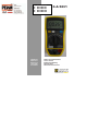 1
1
-
 2
2
-
 3
3
-
 4
4
-
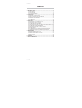 5
5
-
 6
6
-
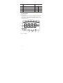 7
7
-
 8
8
-
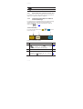 9
9
-
 10
10
-
 11
11
-
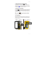 12
12
-
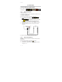 13
13
-
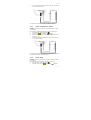 14
14
-
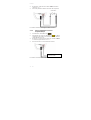 15
15
-
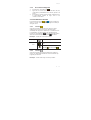 16
16
-
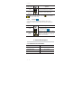 17
17
-
 18
18
-
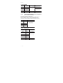 19
19
-
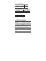 20
20
-
 21
21
-
 22
22
-
 23
23
-
 24
24
-
 25
25
-
 26
26
-
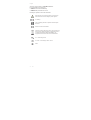 27
27
-
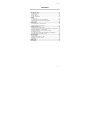 28
28
-
 29
29
-
 30
30
-
 31
31
-
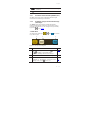 32
32
-
 33
33
-
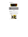 34
34
-
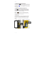 35
35
-
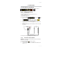 36
36
-
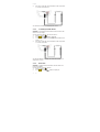 37
37
-
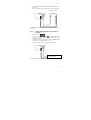 38
38
-
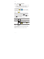 39
39
-
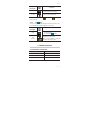 40
40
-
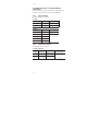 41
41
-
 42
42
-
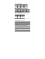 43
43
-
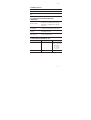 44
44
-
 45
45
-
 46
46
-
 47
47
-
 48
48
-
 49
49
-
 50
50
-
 51
51
-
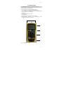 52
52
-
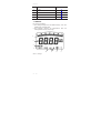 53
53
-
 54
54
-
 55
55
-
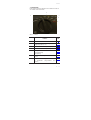 56
56
-
 57
57
-
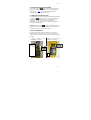 58
58
-
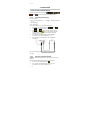 59
59
-
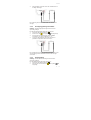 60
60
-
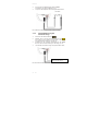 61
61
-
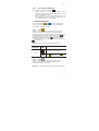 62
62
-
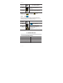 63
63
-
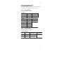 64
64
-
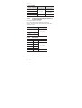 65
65
-
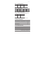 66
66
-
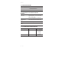 67
67
-
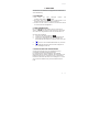 68
68
-
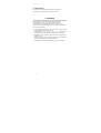 69
69
-
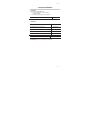 70
70
-
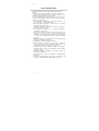 71
71
-
 72
72
-
 73
73
-
 74
74
-
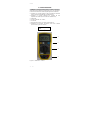 75
75
-
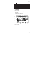 76
76
-
 77
77
-
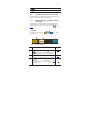 78
78
-
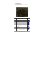 79
79
-
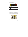 80
80
-
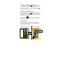 81
81
-
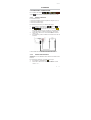 82
82
-
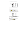 83
83
-
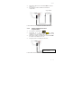 84
84
-
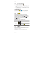 85
85
-
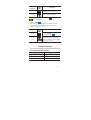 86
86
-
 87
87
-
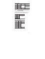 88
88
-
 89
89
-
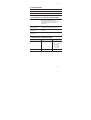 90
90
-
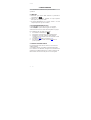 91
91
-
 92
92
-
 93
93
-
 94
94
-
 95
95
-
 96
96
-
 97
97
-
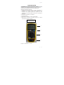 98
98
-
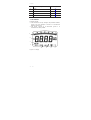 99
99
-
 100
100
-
 101
101
-
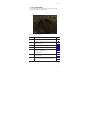 102
102
-
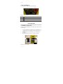 103
103
-
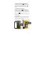 104
104
-
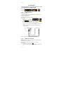 105
105
-
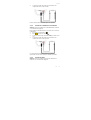 106
106
-
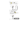 107
107
-
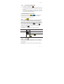 108
108
-
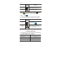 109
109
-
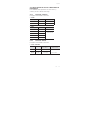 110
110
-
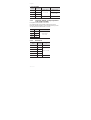 111
111
-
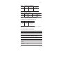 112
112
-
 113
113
-
 114
114
-
 115
115
-
 116
116
-
 117
117


Chauvin-Arnoux CA5231 El manual del propietario
- Categoría
- Multimetros
- Tipo
- El manual del propietario
en otros idiomas
Artículos relacionados
Otros documentos
-
Multimetrix DMM54 MULTIMETER Manual de usuario
-
Amprobe AM-560 & AM-570 Mutimeter Manual de usuario
-
-
Metrix MX 22 Manual de usuario
-
Klein Tools CL380 Manual de usuario
-
-
-