STIHL FS Manual de usuario
- Categoría
- Podadoras de césped
- Tipo
- Manual de usuario

STIHL FS
Manual de instrucciones
Instruction Manual


Original de Instrucciones de
servicio
Impreso en papel blanqueado sin cloro.
Los colores de la impresión contienen aceites vegetales, por lo
que el papel es reciclable.
© ANDREAS STIHL AG & Co. KG, 2019
0458-501-8721-B. VA1.A19.
0000007876_002_E
FS
español
1
Índice
Distinguidos clientes:
Muchas gracias por haber depositado
su confianza en un producto de calidad
de la empresa STIHL.
Este producto se ha confeccionado con
modernos procedimientos de
fabricación y amplias medidas para
afianzar la calidad. Procuramos hacer
todo lo posible para que usted esté
satisfecho con este producto y pueda
trabajar con él sin problemas.
En el caso de que tenga usted alguna
pregunta sobre este producto, diríjase a
su distribuidor STIHL o directamente a
nuestra empresa de distribución.
Atentamente
Dr. Nikolas Stihl
Herramientas de acople 2
Notas relativas a este manual de
instrucciones 2
Indicaciones relativas a la
seguridad y técnica de trabajo 3
Máquinas básicas permitidas 11
Combinaciones permitidas de
herramienta de corte, protector,
empuñadura y cinturón de porte 12
Montar la herramienta de acople 14
Acoplar los dispositivos de
protección 16
Montar la herramienta de corte 17
Ponerse el cinturón de porte 20
Equilibrar la máquina 22
Arrancar / parar el motor 23
Transporte de la máquina 23
Lubricar el engranaje 26
Guardar la máquina 26
Afilar herramientas de corte de
metal 26
Mantenimiento del cabezal de corte 27
Instrucciones de mantenimiento y
conservación 28
Minimizar el desgaste y evitar
daños 29
Componentes importantes 30
Datos técnicos 31
Indicaciones para la reparación 31
Gestión de residuos 32

FS
español
2
La herramienta de acople STIHL se
puede montar en diferentes máquinas
STIHL.
De ello forman parte también los
motores universales para acople
multifunciones en algunos mercados.
En estos mercados, los motores
universales para acople multifunciones
y las herramientas de acople forman
parte juntos del sistema de acople
multifunciones.
Las máquinas a motor permitidas para
el acople figuran en el capítulo
"Máquinas básicas permitidas".
La unidad operativa constituida por la
máquina básica y la herramienta de
acople se denomina máquina en este
manual de instrucciones.
Por lo tanto, los manuales de
instrucciones para la máquina básica y
la herramienta combinada constituyen
el manual de instrucciones completo
para la máquina.
Antes de ponerla en marcha por primera
vez, leer con atención siempre los dos
manuales de instrucciones y guardarlos
en un lugar seguro para posteriores
consultas.
Símbolos gráficos
Todos los símbolos gráficos existentes
en la máquina están explicados en este
manual de instrucciones.
Marcación de párrafos de texto
ADVERTENCIA
Advertencia de peligro de accidente y
riesgo de lesiones para personas y de
daños materiales graves.
INDICACIÓN
Advertencia de daños de la máquina o
de los diferentes componentes.
Perfeccionamiento técnico
STIHL trabaja permanentemente en el
perfeccionamiento de todas las
máquinas y dispositivos; por ello, nos
reservamos los derechos relativos a las
modificaciones del volumen de
suministro en la forma, técnica y
equipamiento.
De los datos e ilustraciones de este
manual de instrucciones no se pueden
deducir por lo tanto derechos a
reclamar.
Herramientas de acople
.
.
.
.
002BA531 KN
+
+
Notas relativas a este
manual de instrucciones

FS
español
3
Prestar o alquilar esta máquina a motor
únicamente a personas que estén
familiarizadas con este modelo y su
manejo – y entregarles siempre los
manuales de instrucciones de la
máquina básica y de la herramienta de
acople.
Emplear la máquina – en función de las
herramientas de corte asignadas –
únicamente para segar hierba así como
para cortar hierba silvestre, arbustos,
maleza, arbolitos o similares.
No se deberá utilizar la máquina para
otros fines – ¡peligro de accidente!
Acoplar únicamente herramientas de
corte o accesorios autorizados
por STIHL para esta máquina a motor o
piezas técnicamente equivalentes. Si
tiene preguntas al respecto, consulte a
un distribuidor especializado.
Emplear sólo herramientas o accesorios
de gran calidad. De no hacerlo, existe el
riesgo de que se produzcan accidentes
o daños en la máquina.
STIHL recomienda emplear
herramientas, herramientas de corte y
accesorios originales de STIHL. Las
propiedades de éstos armonizan
óptimamente con el producto y las
exigencias del usuario.
El protector de la máquina no puede
proteger al usuario contra todos los
objetos (piedras, cristal, alambre, etc.)
que pueda despedir la herramienta de
corte. Estos objetos pueden rebotar en
algún lugar y pegarle luego al usuario.
No realizar modificaciones en la
máquina – ello puede ir en perjuicio de la
seguridad. STIHL excluye cualquier
responsabilidad ante daños personales
y materiales que se produzcan al
emplear equipos de acople no
autorizados.
No emplear hidrolimpiadoras de alta
presión para limpiar la máquina. El
chorro de agua duro puede dañar piezas
de la máquina.
Ropa y equipo
Ponerse la ropa y el equipo
reglamentarios.
No ponerse ropa que se pueda
enganchar en la madera, arbustos o
piezas de la máquina que estén en
movimiento. Tampoco bufanda, corbata
ni artículos de joyería. Recogerse el
pelo largo y sujetarlo (con un pañuelo,
gorra, casco, etc.).
Sólo en el caso de utilizar cabezales de
corte, se admiten como alternativa
zapatos resistentes con suelas
adherentes a prueba de resbalamiento.
ADVERTENCIA
Ponerse un protector para la cara y
prestar atención a que asienten
correctamente. El protector de la cara
no es suficiente para proteger los ojos.
Ponerse un protector acústico
"personal" – p. ej. protectores de oídos.
Indicaciones relativas a la
seguridad y técnica de
trabajo
Se han de tomar medidas
de seguridad especiales
al trabajar con esta
máquina a motor porque
se trabaja con herramien-
tas afiladas y con una
alta herramienta de corte.
Antes de ponerla en ser-
vicio por primera vez, se
han de leer siempre con
atención los dos manua-
les de instrucciones (el
de la máquina básica y el
de la herramienta de aco-
ple) y se han de guardar
luego en un lugar seguro
para posteriores consul-
tas. La inobservancia de
los manuales de instruc-
ciones puede tener
consecuencias mortales.
La ropa deberá ser apro-
piada y no estorbar.
Llevar ropa ceñida – traje
combinado, ningún
abrigo de trabajo.
Ponerse botas protecto-
ras con suelas
adherentes y a prueba de
resbalamiento con cape-
ruza de acero.
Para reducir el peligro de
lesiones oculares,
ponerse unas gafas pro-
tectoras ceñidas según la
norma EN 166. Prestar
atención a que asienten
correctamente las gafas
protectoras.

FS
español
4
Llevar casco protector al realizar
trabajos de aclareo forestal con maleza
alta y si hay peligro de que caigan
objetos.
STIHL ofrece una extensa gama de
equipamiento de protección personal.
Transporte de la máquina
Parar siempre el motor.
Llevar la máquina colgada del cinturón o
equilibrada por el vástago.
Asegurar la herramienta de corte de
metal contra el contacto con un
protector para el transporte, aunque se
trate de distancias cortas – véase
también "Transportar la máquina".
En vehículos: asegurar la máquina para
que no vuelque, no se dañe ni se
derrame combustible.
Antes de arrancar
Comprobar el funcionamiento seguro de
la máquina – tener en cuenta los
capítulos correspondientes del manual
de instrucciones de la máquina básica y
del de la herramienta de acople:
– La combinación de herramienta de
corte, protector, empuñadura y
cinturón de porte deberá estar
permitida y todas las piezas
deberán estar correctamente
montadas
– Herramienta de corte: montaje
correcto, asiento firme y estado
perfecto
– Comprobar los dispositivos de
protección (p. ej. el protector de la
herramienta de corte, plato de
rodadura) en cuanto a daños o bien
desgaste. Renovar las piezas que
estén dañadas. No utilizar la
máquina estando dañado el
protector o con el plato de rodadura
desgastado (si el rotulado y las
flechas ya no son visibles)
– No modificar los dispositivos de
mando ni los de seguridad – trabajar
sólo con el protector montado
– Las empuñaduras tienen que estar
limpias y secas, libres de aceite y
suciedad – esto es importante para
manejar la máquina de forma
segura
– Ajustar el cinturón de porte y la(s)
empuñadura(s) con arreglo a la
estatura. Tener en cuenta el
capítulo "Ponerse el cinturón de
porte"
La máquina sólo se deberá utilizar si
reúne condiciones de seguridad para el
trabajo – ¡peligro de accidente!
Para casos de emergencia al utilizar
cinturones de porte: practicar la
deposición rápida de la máquina. Al
practicar, no arrojar la máquina al suelo,
a fin de evitar que se dañe.
Sujeción y manejo de la máquina
Sujetar siempre la máquina con ambas
manos por las empuñaduras.
Adoptar siempre una postura estable y
segura.
En ejecuciones de empuñadura doble
La mano derecha, en la empuñadura de
mando; la mano izquierda, en la
empuñadura del asidero tubular.
Llevar guantes de trabajo
robustos de material
resistente (p. ej. de
cuero).
002BA079 KN
No tocar piezas calientes
de la máquina ni el
engranaje – ¡peligro de
quemaduras!
002BA055 KN

FS
español
5
En ejecuciones de asidero tubular
cerrado
En ejecuciones de asidero tubular
cerrado y asidero tubular cerrado con
estribo (limitador de paso), la mano
izquierda, en el asidero tubular cerrado;
la derecha, en la empuñadura de mando
– también al tratarse de zurdos.
Agarrar firmemente las empuñaduras
con los pulgares.
Durante el trabajo
Adoptar siempre una postura estable y
segura.
En caso de peligro inminente o bien de
emergencia, parar inmediatamente el
motor – poner el cursor del mando
unificado/el interruptor de
parada/pulsador de parada en 0 o
bien STOP.
En un amplio círculo en torno al lugar de
trabajo puede existir un peligro de
accidente originado por objetos
despedidos, por lo que no se deberá
permitir la presencia de otras personas
en un círculo de 15 m. Mantenerse a
esta distancia también respecto de
objetos (vehículos, ventanas) – ¡peligro
de daños materiales! También a una
distancia de más de 15 m no se puede
excluir que exista peligro.
Prestar atención a que el ralentí sea
perfecto, a fin de que deje de girar la
herramienta de corte al soltar el
acelerador.
Controlar o bien corregir periódicamente
el ajuste del ralentí. Si pese a ello gira la
herramienta de corte en ralentí,
encargar la reparación a un distribuidor
especializado – véase el manual de
instrucciones del motor universal.
STIHL recomienda un distribuidor
especializado STIHL.
Prestar atención en caso de que el suelo
esté congelado, mojado, nevado, en
pendientes y terrenos irregulares, etc. –
¡peligro de resbalar!
Prestar atención a los obstáculos:
tocones, raíces – ¡peligro de tropezar!
Trabajar sólo estando de pie en el suelo,
no hacerlo nunca en lugares inestables,
jamás sobre escaleras o desde una
plataforma elevadora.
Ni con una mano sola.
Al llevar un protector para los oídos, hay
que prestar más atención y tener más
precaución – se perciben peor las
señales de aviso de peligro (gritos,
señales acústicas y similares).
Hacer siempre oportunamente pausas
en el trabajo para prevenir el cansancio
y el agotamiento – ¡peligro de accidente!
Trabajar con tranquilidad y prudencia –
sólo en buenas condiciones de luz y
visibilidad. Trabajar con precaución, no
poner en peligro a otras personas.
En el caso de que la máquina haya
sufrido percances para los que no está
prevista (p. ej., golpes o caídas), se ha
de comprobar sin falta que funcione de
forma segura antes de continuar el
trabajo – véase también "Antes de
arrancar".
Comprobar sobre todo la operatividad
de los dispositivos de seguridad. De
ningún modo se deberá seguir
trabajando con máquinas que ya no
sean seguras. En caso de dudas,
consultar a un distribuidor
especializado.
002BA080 KN
15m (50ft)
Evitar el contacto con la
herramienta de corte –
¡peligro de lesiones!
No trabajar nunca
sin el protector
apropiado para la
máquina y la herra-
mienta de corte –
¡peligro de
lesiones!

FS
español
6
Trabajar con especial precaución en
terrenos de poca visibilidad y con mucha
vegetación.
Al segar zarzales altos, por debajo de
matorrales y setos: la altura de trabajo
con la herramienta de corte deberá ser
al menos de 15 cm – no poner en peligro
los animales.
Comprobar la herramienta de corte, a
intervalos breves y hacerlo
inmediatamente si se percibe algún
cambio:
– Parar el motor, sujetar la máquina
de forma segura, presionar la
herramienta de corte contra el suelo
para frenarla
– Revisar el estado y asiento firme,
prestar atención a las fisuras
– Fijarse en el estado de afilado
– Cambiar inmediatamente las
herramientas de corte dañadas o
embotadas, incluso en el caso de
fisuras capilares insignificantes
Limpiar regularmente el alojamiento de
la herramienta de corte de restos de
hierba y maleza – quitar las
obstrucciones de la zona de la
herramienta de corte o del protector.
Parar el motor para cambiar la
herramienta de corte – ¡peligro de
lesiones!
Utilización de cabezales de corte
Completar el protector de la herramienta
de corte con las piezas de acople
indicadas en el manual de instrucciones.
Emplear sólo un protector con la cuchilla
debidamente montada, a fin de que los
hilos de corte se limiten a la longitud
admisible.
Para reajustar el hilo en cabezales de
corte de reajuste manual, parar sin falta
el motor – ¡peligro de lesiones!
El uso indebido de la máquina con hilos
demasiado largos reduce el número de
revoluciones de trabajo del motor.
Debido al permanente resbalamiento
del embrague que ello origina, se
produce un calentamiento excesivo y la
avería de piezas importantes (como
p. ej., el embrague, piezas de la carcasa
de plástico) – ¡peligro de lesiones! por
ejemplo, por girar la herramienta de
corte en ralentí.
Empleo de herramientas de corte de
metal
STIHL recomienda emplear únicamente
herramientas de corte de metal
originales STIHL. Las propiedades de
éstas están armonizadas óptimamente
con la máquina y las exigencias del
usuario.
Las herramientas de corte de metal
giran con mucha rapidez. Al hacerlo, se
generan fuerzas que actúan sobre la
máquina, la herramienta misma y el
material objeto de corte.
Las herramientas de corte de metal se
han de afilar periódicamente según las
prescripciones.
Las herramientas de corte de metal
afiladas desigualmente provocan un
desequilibrio, que puede cargar
extremadamente la máquina – ¡peligro
de rotura!
Los filos romos o indebidamente
afilados pueden originar un alto
esfuerzo de la herramienta de corte de
metal – ¡peligro de lesiones! por las
piezas rajadas o rotas
Revisar la herramienta de corte de metal
cada vez que tope con objetos duros
(p. ej. piedras, rocas, piezas de metal)
(p. ej. en cuanto a fisuras y
deformaciones). Las rebabas y otros
recrecimientos de material visibles se
han de quitar (lo mejor es hacerlo con
una lima), dado que se pueden soltar en
el transcurso del trabajo y salir
despedidos – ¡peligro de lesiones!
Si una herramienta de corte de metal en
giro topa en una piedra u otro objeto
duro, pueden generarse chispas por lo
que, en determinadas circunstancias
Inspeccionar el terreno:
pueden salir despedidos
objetos sólidos – pie-
dras, piezas de metal o
similares – también por
encima de 15 m – ¡peli-
gro de lesiones! – y
pueden dañar la herra-
mienta de corte así como
otros objetos
(p. ej. vehículos aparca-
dos, cristales de
ventanas) (daños
materiales).
El engranaje se calienta
durante el trabajo. No
tocar la caja del engra-
naje – ¡peligro de
quemaduras!

FS
español
7
pueden encenderse materiales que
sean fácilmente inflamables. También
las plantas y maleza en estado seco son
fácilmente inflamables, especialmente
en condiciones meteorológicas de
mucho calor y sequedad. Si existe
peligro de incendio, no emplear
herramientas de corte de metal cerca de
sustancias fácilmente inflamables,
plantas secas o maleza. Preguntar sin
falta a la autoridad forestal competente
si existe peligro de incendio.
No seguir utilizando herramientas de
corte que estén dañadas o agrietadas ni
repararlas – soldándolas o
enderezándolas – deformaciones
(desequilibrio).
Las partículas o piezas rotas pueden
soltarse y alcanzar a gran velocidad al
usuario u otras personas – ¡y originar las
más graves lesiones!
Para reducir los peligros mencionados
que se generan durante el
funcionamiento de una herramienta de
corte de metal, la herramienta empleada
no deberá tener de ningún modo un
diámetro demasiado grande ni deberá
pesar demasiado. Tiene que estar
fabricada con materiales de calidad
suficiente y tener una geometría
apropiada (forma, espesor).
Una herramienta de corte de metal que
no haya sido fabricada por STIHL no
deberá pesar más, ni ser más gruesa, ni
tener una conformación diferente ni un
diámetro superior al de la herramienta
de corte de metal STIHL más grande
permitida para esta máquina a motor –
¡peligro de lesiones!
Después de trabajar
Tras finalizar el trabajo o antes de
ausentarse de la máquina: parar el
motor.
Eliminar con regularidad el polvo, la
suciedad, la tierra y restos de plantas de
la herramienta de corte al finalizar el
trabajo – emplear guantes – ¡peligro de
lesiones!
Para la limpieza, no emplear sustancias
que disuelvan la grasa.
Tras limpiar a fondo las herramientas de
corte de metal, humedecer la superficie
de las mismas con un agente
anticorrosivo.
Símbolos en los dispositivos de
protección
Una flecha en el protector para las
herramientas de corte indica el sentido
de giro de las mismas.
Algunos de los siguientes símbolos se
encuentran en el lado exterior del
protector y hacen referencia a la
combinación admisible de herramienta
de corte / protector.
Mantenimiento y reparaciones
Efectuar con regularidad los trabajos de
mantenimiento de la máquina. Realizar
únicamente trabajos de mantenimiento
y reparaciones que estén descritos en el
manual de instrucciones de la máquina
El protector se puede
emplear junto con cabe-
zales de corte.
El protector no se puede
emplear junto con cabe-
zales de corte.
El protector se puede
emplear junto con hojas
cortahierbas.
El protector no se puede
emplear junto con hojas
cortahierbas.
El protector se puede
emplear junto con hojas
cortamalezas.
El protector no se puede
emplear junto con cuchi-
llas cortamalezas.
El protector no se puede
emplear junto con cuchi-
llas trituradoras.
El protector no se puede
emplear junto con hojas
de sierra circular.

FS
español
8
básica y en el de la herramienta de
acople. Encargar todos los demás
trabajos a un distribuidor especializado.
STIHL recomienda encargar los
trabajos de mantenimiento y las
reparaciones siempre a un distribuidor
especializado STIHL. Los distribuidores
especializados STIHL siguen
periódicamente cursillos de instrucción
y tienen a su disposición las
informaciones técnicas.
Emplear sólo repuestos de gran calidad.
De no hacerlo, existe el peligro de que
se produzcan accidentes o daños en la
máquina. Si tiene preguntas al respecto,
consulte a un distribuidor especializado.
STIHL recomienda emplear piezas de
repuesto originales STIHL. Las
propiedades de éstas armonizan
óptimamente con el producto y las
exigencias del usuario.
Para la reparación, el mantenimiento y
la limpieza, parar siempre el motor –
¡peligro de lesiones!
Cinturón de porte
El cinturón de porte está contenido en el
volumen de suministro o se puede
adquirir como accesorio especial.
N Usar el cinturón de porte
N Enganchar la máquina con el motor
en marcha en el cinturón de porte
Las hojas cortahierbas y las cuchillas
cortamalezas se han de usar en
combinación con un cinturón de porte
(cinturón sencillo).
Las hojas de sierra circular se han de
usar en combinación con un cinturón
doble provisto de dispositivo de soltado
rápido.
Cabezal de corte con hilo de corte
Para un "corte" suave y blando – para
cortar nítidamente también bordes
resquebrajados en torno a árboles y
postes de vallas, etc. – se lesiona
menos la corteza del árbol.
En el volumen de suministro del cabezal
de corte existe una hoja de
instrucciones adjuntada. Poner el hilo en
el cabezal de corte sólo según las
indicaciones contenidas en la hoja de
instrucciones.
ADVERTENCIA
No sustituir el hilo de corte por alambres
o cuerdas – ¡peligro de lesiones!
000BA015 KN

FS
español
9
Cabezal de corte con cuchillas de
plástico – STIHL PolyCut
Para segar bordes de prados silvestres
(sin postes, vallas, árboles ni obstáculos
similares).
¡Tener en cuenta las marcas de
desgaste!
Si se ha roto una de las marcas del
cabezal de corte PolyCut hacia abajo
(flecha): no volver a utilizar el cabezal de
corte y sustituirlo por uno nuevo.
¡Peligro de lesiones por piezas de la
herramienta despedidas!
Observar sin falta las indicaciones de
mantenimiento para el cabezal de corte
PolyCut.
En lugar de las cuchillas de plástico, se
puede poner también hilo en el cabezal
de corte PolyCut.
En el volumen de suministro del cabezal
de corte existen hojas de instrucciones
adjuntadas. Poner cuchillas de plástico
o hilo en el cabezal de corte sólo según
las indicaciones contenidas en las hojas
de instrucciones.
ADVERTENCIA
No poner alambres o cuerdas en lugar
del hilo de corte – ¡peligro de lesiones!
Peligro de rebote en el caso de
herramientas de corte de metal
ADVERTENCIA
Existe un riesgo de rebote aumentado
cuando la herramienta incide en un
obstáculo por el sector negro.
Hoja cortahierbas
Sólo para hierba y malas hierbas – guiar
la máquina como una guadaña.
ADVERTENCIA
El uso inapropiado puede dañar la hoja
cortahierbas – ¡peligro de lesiones! por
piezas despedidas
Afilar la hoja cortahierbas cuando el
embotamiento sea perceptible,
procediendo con arreglo a las
prescripciones.
Cuchilla cortamalezas
Para cortar hierba enredada, aclarar
hierba silvestre y matorrales y para el
aclareo de arboleda joven con un
diámetro de tronco de máximo 2 cm – no
cortar madera más gruesa – ¡peligro de
accidente!
002BA049 KN
Al trabajar con herra-
mientas de corte de
metal, existe el peligro de
rebote cuando la herra-
mienta incide en un
obstáculo sólido (el
tronco de un árbol, rama,
tocón, piedra o algo simi-
lar). La máquina es
lanzada entonces hacia
atrás – en sentido contra-
rio al del giro de la
herramienta.
002BA135 KN
000BA020 KN

FS
español
10
Al cortar hierba y aclarar arboleda joven,
guiar la máquina como una guadaña,
manteniendo la herramienta muy cerca
del suelo.
Para aclarar hierba silvestre y
matorrales, "sumergir" la cuchilla
cortamalezas desde arriba en las
plantas – con ello se tritura todo – al
hacerlo, no sostener la herramienta de
corte a una altura superior a las
caderas.
Con esta técnica de trabajo se requiere
máxima atención. Cuanto mayor es la
distancia de la herramienta de corte
respecto del suelo, tanto mayor es el
riesgo de que se despidan partículas
hacia los lados – ¡peligro de lesiones!
Atención: El uso inapropiado puede
dañar la cuchilla cortamalezas – ¡peligro
de lesiones! por piezas despedidas
Para disminuir el riesgo de accidente,
tener en cuenta sin falta lo siguiente:
– Evitar el contacto con piedras,
cuerpos de metal o similares
– No cortar madera o matorrales de
un diámetro superior a 2 cm –
emplear una hoja de sierra circular
para diámetros más grandes
– Controlar periódicamente la cuchilla
cortamalezas en cuanto a daños –
no seguir utilizando la cuchilla
cortamalezas si está dañada
– Afilar periódicamente la cuchilla
cortamalezas, si se percibe su
embotamiento, según las
prescripciones y – de ser necesario
– equilibrarla (STIHL recomienda
acudir a un distribuidor
especializado STIHL)
Hoja de sierra circular
Para cortar matorrales y árboles de
hasta 4 cm de diámetro de tronco.
El mejor rendimiento de corte se obtiene
a pleno gas y con una presión de
avance uniforme.
Emplear las hojas de sierra circular sólo
con el tope apropiado para el diámetro
de la herramienta de corte.
ADVERTENCIA
Se deberá evitar sin falta el contacto de
la hoja de sierra circular con piedras y
tierra – existe el peligro de que se
formen grietas. Afilar la herramienta a
tiempo y según las prescripciones – los
dientes romos pueden provocar la
formación de grietas y, con ello, la rotura
de la hoja de sierra – ¡peligro de
accidente!
Al talar, mantener una distancia de al
menos dos veces la longitud del árbol
respecto del lugar de trabajo más
cercano.
Peligro de rebote
El peligro de rebote es muy alto en el
sector negro: es este sector no se
deberá aplicar nunca la hoja para serrar
ni se deberá cortar nada.
En el sector gris existe también riesgo
de rebote: este sector lo pueden utilizar
únicamente personas con experiencia y
formación especial en técnicas de
trabajo especiales.
En el sector blanco se puede trabajar
con bajo nivel de rebote y con facilidad.
Aplicar la herramienta siempre en este
sector para cortar.
002BA355 KN
002BA509 KN
002BA068 KN

FS
español
11
ADVERTENCIA
Esta herramienta de acople sólo se
permite con uno de los siguientes
sistemas de empuñadura fijado a la
máquina básica:
– Empuñadura doble.
– Asidero tubular cerrado sin estribo
(limitador de paso) en el que se
puede montar posteriormente un
estribo.
– Asidero tubular cerrado con estribo
(limitador de paso).
El servicio de esta herramienta de
acople se permite con las siguientes
máquinas básicas:
Máquinas con empuñadura doble o
asidero tubular cerrado con estribo
– KA 85 R, KA 120, KA 250
ADVERTENCIA
No está permitida la combinación con
otras máquinas básicas que no sean las
anteriormente mencionadas – ¡peligro
de accidente y lesiones!
ADVERTENCIA
Emplear las herramientas de corte
únicamente en función de las
indicaciones del capítulo
"Combinaciones permitidas de
herramienta de corte, protector,
empuñadura y cinturón de porte" –
¡peligro de accidente y lesiones!
ADVERTENCIA
Empleo del limitador de paso (estribo) –
véase "Combinaciones permitidas de
herramienta de corte, protector,
empuñadura y cinturón de porte" –
¡peligro de accidente y lesiones!
Máquinas básicas permitidas
002BA658 KN

FS
español
12
Combinaciones permitidas de herramienta de corte, protector, empuñadura y cinturón de porte
Herramienta de corte Protector, tope Empuñadura Cinturón de porte
20
19
18
17
16
27
25
26
27
27
26
28
24
24
23
22
24
23
22
15
14
0000-GXX-5210-A1
8
13
11
10
9
12
1
2
3
4
5 6
7
21

FS
español
13
Combinaciones permitidas
En función de la herramienta de corte,
seleccionar de la tabla la combinación
correcta
ADVERTENCIA
Por motivos de seguridad, únicamente
se permite combinar entre sí las
herramientas de corte y las ejecuciones
de protector, empuñadura y cinturón de
porte que se encuentren dentro de una
línea de la tabla. No se permiten otras
combinaciones – ¡peligro de accidente!
Herramientas de corte
Cabezales de corte
1 STIHL SuperCut 20-2
2 STIHL AutoCut 25-2
3 STIHL AutoCut C 26-2
4 STIHL AutoCut 36-2
5 STIHL TrimCut 31-2
6 STIHL DuroCut 20-2
7 STIHL PolyCut 20-3
Herramientas de corte de metal
8 Hoja cortahierbas 230-2
(Ø 230 mm)
9 Hoja cortahierbas 260-2
(Ø 260 mm)
10 Hoja cortahierbas 230-4
(Ø 230 mm)
11 Hoja cortahierbas 230-8
(Ø 230 mm)
12 Hoja cortahierbas 250-40 Spezial
(Ø 250 mm)
13 Cuchilla cortamalezas 250-3
(Ø 250 mm)
14 Hoja de sierra circular 200-80,
diente en pico
1)
(Ø 200 mm)
15 Hoja de sierra circular 200-22,
diente en cincel
1)
(Ø 200 mm)
ADVERTENCIA
No se permiten hojas cortahierbas,
cuchillas cortamalezas y hojas de sierra
circular de otros materiales que no sea
metal.
Protectores
16 Protector para cabezales de corte
17 Protector con
18 Faldón y cuchilla solo para
cabezales de corte
19 Protector sin faldón y cuchilla para
las herramientas de corte de metal
20 Tope para hojas de sierra circular
Empuñaduras
21 Asidero tubular cerrado sin estribo
22 Asidero tubular cerrado con
23 estribo (limitador de paso)
24 Empuñadura doble
Cinturones de porte
25 Se puede emplear un cinturón de
porte sencillo
26 Se tiene que emplear cinturón de
porte sencillo
27 Se puede emplear cinturón de porte
doble
28 Se tiene que emplear cinturón de
porte doble
1)
Solo se permite en KA 120, KA 250

FS
español
14
Preparar el acople
ADVERTENCIA
Para modificar el montaje de la máquina
a motor básica, parar siempre el motor –
¡peligro de lesiones!
INDICACIÓN
Realizar el acople y el desmontaje de la
herramienta de acople siempre en un
lugar limpio.
N Depositar la máquina a motor
básica sobre el apoyo de la misma
Retirar la caperuza
Si en la máquina a motor básica existe
una caperuza en el extremo del vástago:
N Retirar la caperuza del extremo del
vástago (y guardarla)
Si al retirar la caperuza se extrajera el
tapón del vástago:
N Introducir presionando el tapón en
el vástago hasta el tope
Desmontar el engranaje o la
herramienta de acople
Si en la máquina a motor básica existe
un engranaje o bien una herramienta de
acople, entonces habrá que desmontar
estos.
Montar la herramienta de
acople
413BA014 KN
002BA248 KN
228BA092 KN
BF
228BA090 KN
FCS
228BA091 KN
FCS
0000-GXX-1866-A0
FH/HL
0000-GXX-0272-A0
HT
SP, SP 20
228BA084 KN

FS
español
15
N En la máquina a motor básica,
aflojar los tornillos de apriete
(flechas) de la carcasa del
engranaje – no desenroscarlos
N Retirar el engranaje del vástago
Si el árbol de accionamiento se sale del
vástago al retirar el engranaje:
N Introducir el árbol de accionamiento
en el vástago
El árbol de accionamiento sólo debe
sobresalir L = 22 mm (7/8 in.) del
vástago.
Si no se alcanza la medida (L):
N Girar lentamente el árbol de
accionamiento ejerciendo una
ligera presión hasta obtenerse la
medida indicada
Montar el engranaje
N Hacer una marca en el extremo del
vástago a una distancia A = 70 mm
(2,75 in.) (con lápiz o rotulador de
color)
N Depositar la máquina apoyándola
sobre el suelo por el protector
(flecha) existente en el motor
N Aflojar el tornillo de apriete (1) del
engranaje – no desenroscarlo
N Montar el engranaje (2) en el
vástago (3) hasta el tope – al
hacerlo, girar un poco el engranaje
en vaivén hasta que la caja haya
alcanzado la marca en el vástago
(flecha grande) o la haya cubierto
Otra posibilidad de comprobación: el
vástago estará correctamente montado
cuando cierre por completo el intersticio
de apriete del engranaje (flecha
pequeña).
N Apretar firmemente el tornillo de
apriete
ADVERTENCIA
El engranaje no deberá poder girarse ya
sobre el vástago.
En máquinas con asidero tubular
cerrado
N Aflojar los tornillos en el asidero
tubular cerrado
228BA085 KN
SP 10
381BA015 KN
L
413BA015 KN
A
0000-GXX-0552-A0
1
3
2
0000-GXX-0553-A0

FS
español
16
N Alinear el asidero tubular
cerrado (1) y ponerlo en la posición
más favorable para el usuario y la
aplicación concreta
Recomendación: distancia
A = aprox. 20 cm (aprox. 8 in.).
N Apretar los tornillos en el asidero
tubular cerrado
Montar el protector
1 Protector para herramientas de
segar
2 Protector para cabezales de corte
Los protectores (1) y (2) se fijan del
mismo modo al engranaje.
N Colocar el protector sobre el
engranaje
N Enroscar los tornillos (3) y
apretarlos
Montar el faldón y la cuchilla
ADVERTENCIA
Peligro de lesiones por objetos
despedidos y el contacto con la
herramienta de corte. El faldón y la
cuchilla se tienen que acoplar al
protector (1) siempre que se empleen
cabezales de corte.
Montar el faldón
N Montar la ranura de guía del faldón
en la regleta del protector hasta que
encastre
0000-GXX-3877-A0
1
A
Acoplar los dispositivos de
protección
002BA636 KN
2
1
3
3
002BA637 KN

FS
español
17
Desmontar el faldón
N Presionar en el orificio del faldón
con el pasador y, al mismo tiempo,
empujar un poco el faldón hacia la
izquierda con dicho pasador
N Quitar por completo el faldón del
protector
Montar la cuchilla
N Montar la cuchilla en la ranura de
guía del faldón
N Enroscar el tornillo y apretarlo
Montar el tope
ADVERTENCIA
Peligro de lesiones por objetos
despedidos y el contacto con la
herramienta de corte. El tope (6) se
tiene que montar siempre que se
empleen hojas de sierra circular.
N Colocar el tope (6) en la brida del
engranaje
N Enroscar los tornillos (7) y
apretarlos
Depositar la máquina
N Parar el motor
N Depositar la máquina, de manera
que el alojamiento para la
herramienta de corte esté orientado
hacia arriba
Piezas de fijación para herramientas de
corte
En función de la herramienta de corte
suministrada en el equipamiento básico
de una máquina nueva, puede variar
también el volumen de suministro de
piezas de fijación para la herramienta de
corte.
1.
2.
002BA646 KN
002BA638 KN
7
002BA639 KN
6
Montar la herramienta de
corte
002BA104 KN

FS
español
18
Volumen de suministro sin piezas de
fijación
Sólo se pueden montar cabezales de
corte que se fijen en el árbol (1) mismo.
Volumen de suministro con piezas de
fijación
Se pueden montar cabezales de corte y
herramientas de corte de metal.
Para ello, según la ejecución de la
herramienta de corte, se precisa
adicionalmente la tuerca (2), el plato de
rodadura (3) y el disco de presión (4).
Estas piezas se encuentran en el juego
de piezas que se suministra con la
máquina y se pueden adquirir como
accesorio especial.
Bloquear el árbol
Para montar y desmontar las
herramientas de corte, se ha de
bloquear el árbol (1) con el pasador (2)
o el destornillador acodado (2). Las
piezas están contenidas en el volumen
de suministro y se pueden adquirir como
accesorio especial, respectivamente.
N Oprimir ligeramente el pasador (2)
o el destornillador acodado (2) en el
orificio (3) existente en el engranaje
– hasta el tope
N Girar el árbol, la tuerca o la
herramienta de corte hasta que
encastre el pasador y se bloquee el
árbol
Desmontar las piezas de fijación
N Bloquear el árbol
N Aflojar la tuerca (2) con la llave
universal (1) en sentido horario
(rosca a la izquierda) y
desenroscarla
N Quitar el disco de presión (3) del
árbol (4), no quitar el plato de
presión (5)
Montar la herramienta de corte
ADVERTENCIA
Emplear el protector apropiado para la
herramienta de corte – véase "Montar
los dispositivos de protección".
1
0812BA019 KN
0812BA020 KN
2
3
4
2
3
1
002BA569 KN
2
3
4
2
271BA057 KN
1
5

FS
español
19
Montar el cabezal de corte con
empalme roscado
Guardar bien la hoja de instrucciones
adjuntada para el cabezal de corte.
N Girar el cabezal de corte en sentido
antihorario en el árbol (1) hasta el
tope
N Bloquear el árbol
N Apretar el cabezal de corte
INDICACIÓN
Volver a quitar la herramienta de
bloquear el árbol.
Desmontar el cabezal de corte
N Bloquear el árbol
N Girar el cabezal de corte en sentido
horario
Montar herramientas de corte de metal
Guardar bien la hoja de instrucciones
adjuntada y el embalaje de la
herramienta de corte de metal.
ADVERTENCIA
Ponerse guantes protectores – peligro
de lesiones por filos de corte afilados.
Montar siempre sólo una herramienta de
corte de metal
Colocar correctamente la herramienta
de corte
La herramientas de corte de (2, 4, 5)
pueden estar orientadas en el sentido
que se desee – dar la vuelta
periódicamente a estas herramientas
para evitar un desgaste unilateral.
Las aristas de corte de las herramientas
de corte (1, 3, 6, 7) tienen que estar
orientadas en sentido horario.
ADVERTENCIA
Tener en cuenta la flecha para el sentido
de giro existente en el lado interior del
protector.
N Colocar la herramienta de corte (8)
en el plato de presión (9)
ADVERTENCIA
El collar (flecha) tiene que penetrar en el
orificio de la herramienta de corte.
Fijar la herramienta de corte
N Colocar el disco de presión (10) – el
abombado, hacia arriba
N Colocar el plato de rodadura (11)
N Bloquear el árbol (12)
N Enroscar la tuerca (13) en el árbol
en sentido antihorario y apretarla
empleando para ello la llave
universal (14)
1
002BA385 KN
3
1
4
6
7
5
681BA042 KN
2
10
8
9
11
12
13
14
681BA161 KN

FS
español
20
ADVERTENCIA
Sustituir la tuerca si gira con demasiada
facilidad.
INDICACIÓN
Volver a quitar la herramienta de
bloquear el árbol.
Montar la herramienta de corte de metal
ADVERTENCIA
Ponerse guantes protectores – peligro
de lesiones por filos de corte afilados
N Bloquear el árbol
N Aflojar la tuerca en sentido horario
N Retirar la herramienta de corte y sus
piezas de fijación del engranaje – al
hacerlo, no quitar el plato de
presión (9)
No todas las máquinas básicas están
equipadas con un cinturón de porte.
El cinturón de porte se puede adquirir
como "Accesorio especial".
El tipo y la ejecución del cinturón de
porte y del mosquetón dependen del
mercado y la máquina básica.
Para el empleo del cinturón de porte –
véase "Combinaciones permitidas de
herramienta de corte, protector,
empuñadura y cinturón de porte".
Cinturón sencillo
N Ponerse el cinturón sencillo (1)
N Ajustar la longitud del cinturón – el
mosquetón (2) tiene que quedar un
ancho de mano por debajo de la
cadera derecha al estar colgada la
máquina
N Equilibrar la máquina – véase
"Equilibrar la máquina"
Ponerse el cinturón de porte
1
0000-GXX-0503-A0
2

FS
español
21
Cinturón doble
N Ponerse el cinturón doble (1) y
cerrar la placa broche (3)
N Ajustar la longitud del cinturón – el
mosquetón (2) tiene que quedar un
ancho de mano por debajo de la
cadera derecha al estar colgada la
máquina
N Equilibrar la máquina – véase
"Equilibrar la máquina"
Enganchar la máquina en el cinturón de
porte
El tipo y la ejecución del cinturón de
porte y del mosquetón dependen del
mercado.
N Enganchar el mosquetón (1) en la
argolla de porte (2) en el vástago
Desenganchar la máquina del cinturón
de porte
N Oprimir la brida en el mosquetón (1)
y retirar del gancho la argolla de
porte (2)
Deposición rápida de la máquina
ADVERTENCIA
En el momento en que esté surgiendo
un peligro, se ha de arrojar rápidamente
la máquina. Practicar la deposición
rápida de la máquina. Al practicar, no
arrojar la máquina al suelo, a fin de
evitar que se dañe.
Para arrojarla, hacer prácticas con los
dispositivos de soltado tal como se
especifica en "Desenganchar la
máquina del cinturón de porte".
3
0000-GXX-0504-A0
2
1
1
002BA660 KN
2
1
1
2
2
002BA661 KN
2
1
1
1
2
2

FS
español
22
Si se emplea un cinturón simple:
practicar la forma de deslizarlo del
hombro.
Si se emplea un cinturón doble:
practicar en este cinturón la apertura
rápida de la placa de cierre y la forma de
deslizarlo de los hombros.
Equilibrar la máquina
En función de la herramienta de corte
montada, la máquina se equilibra de
forma diferente.
Hasta que se cumplan las condiciones
que figuran en "Posiciones de
equilibrado", efectuar los siguientes
pasos:
N Aflojar el tornillo (1)
N Desplazar la argolla de porte (2)
N Apretar ligeramente el tornillo
N Dejar balancearse la máquina
N Comprobar la posición final de
balanceo
Posiciones de equilibrado
Las herramientas de corte (A), como los
cabezales de corte, las hojas
cortahierbas y las cuchillas
cortamalezas
N Deben descansar ligeramente
sobre el suelo
Hojas de sierra circular (B)
N Deben "flotar" unos 20 cm (8 in)
sobre el suelo
Una vez obtenida la posición de
equilibrado correcta:
N Apretar el tornillo de la argolla de
porte
Equilibrar la máquina
002BA662 KN
1
2
A
002BA034 KN
B
002BA035 KN

FS
español
23
Arrancar el motor
Para arrancar, tener en cuenta por
principio las indicaciones de servicio de
la máquina básica
N Poner la máquina en el suelo en
una posición estable: el apoyo del
motor y el protector para la
herramienta de corte constituyen el
apoyo.
N En caso de estar montado: quitar de
la herramienta de corte el protector
para el transporte
La herramienta de corte no deberá tocar
el suelo ni objeto alguno – ¡peligro de
accidente!
N Adoptar una postura segura –
posibilidades: de pie, agachado o
arrodillado
N Con la mano izquierda, presionar
firmemente la máquina contra el
suelo – al hacerlo, no tocar el
acelerador, el bloqueo del mismo ni
el cursor del mando unificado
INDICACIÓN
¡No poner el pie sobre el vástago ni
arrodillarse encima del mismo!
ADVERTENCIA
Si se arranca el motor, al ponerse en
marcha se puede accionar enseguida la
herramienta de corte – por ello,
inmediatamente después de ponerse en
marcha, pulsar ligera y brevemente el
acelerador – el motor pasa a ralentí.
El resto del proceso de arranque se
describe en el manual de instrucciones
de la máquina básica.
Parar el motor
N Véase el manual de instrucciones
para la máquina básica
Emplear el protector para el transporte
El tipo de protector para el transporte
está en función del tipo de herramienta
de corte de metal adjuntado en el
volumen de suministro de la máquina.
Los protectores para el transporte se
pueden adquirir como accesorio
especial.
Hojas cortahierbas 230 mm
Arrancar / parar el motor
233BA020 KN
233BA014 KN
Transporte de la máquina
681BA268 KN
681BA269 KN

FS
español
24
Cuchilla cortamalezas 250 mm
Hojas cortahierbas hasta 260 mm
N Desenganchar el estribo de
sujeción del protector para el
transporte
N Girar el estribo de sujeción hacia
fuera
681BA270 KN
681BA272 KN
681BA268 KN
681BA269 KN
681BA271 KN
681BA272 KN
681BA301 KN
681BA275 KN
1.
2.

FS
español
25
N Aplicar desde abajo el protector
para el transporte a la herramienta
de corte
N Girar el estribo de sujeción hacia
dentro
N Enganchar el estribo de sujeción
del protector para el transporte
Hojas de sierra circular
N Desenganchar el estribo de
sujeción del protector para el
transporte
N Girar el estribo de sujeción hacia
fuera
N Aplicar desde abajo el protector
para el transporte a la herramienta
de corte; al hacerlo, prestar
atención a que el tope quede
centrado en el rebaje
N Girar el estribo de sujeción hacia
dentro
N Enganchar el estribo de sujeción
del protector para el transporte
681BA305 KN
2.
681BA311 KN
681BA302 KN
681BA275 KN
1.
2.
681BA276 KN
681BA277 KN
2.

FS
español
26
Controlar la grasa del engranaje cada
25 horas de servicio y engrasarlo si lo
requiere su estado:
N Desenroscar el tornillo de cierre (1)
N En caso que no se vea grasa en el
lado interior del tornillo de cierre (1):
enroscar el tubo (2) con grasa para
engranajes STIHL (accesorio
especial)
N Introducir presionando 5 g (1/5 oz.)
de grasa del tubo (2) en el
engranaje
INDICACIÓN
No llenar por completo el engranaje de
grasa.
N Desenroscar el tubo (2)
N Enroscar el tornillo de cierre (1) y
apretarlo
En pausas de servicio a partir de unos
3meses
N Quitar la herramienta de corte,
limpiarla y revisarla. Tratar las
herramientas de corte de metal con
aceite protector.
N Guardar la máquina en un lugar
seco y seguro. Protegerla contra el
uso por personas ajenas (p. ej. por
niños).
N Si el desgaste es escaso, afilar las
herramientas de corte con una lima
apropiada (accesorio especial) – si
el desgaste es elevado y existen
mellas, afilarlas con una afiladora o
encargar el servicio al distribuidor
especializado – STIHL recomienda
el distribuidor especializado STIHL
N Afilar con frecuencia, quitar poco
material: para un simple reafilado
suelen ser suficientes dos o tres
pasadas con la lima
N Afilar uniformemente las hojas de la
cuchilla (1) – no modificar el
contorno de la hoja básica (2)
Para más instrucciones de afilado,
consulte en el embalaje de la
herramienta de corte. Guardar el
embalaje por este motivo.
Lubricar el engranaje
1
0000-GXX-0536-A0
Guardar la máquina Afilar herramientas de corte
de metal
2
1
002BA083 KN
2
1
2
2
1
1

FS
español
27
Equilibrado
N Reafilar unas 5 veces, comprobar
luego las herramientas de corte con
el dispositivo de equilibrado STIHL
(accesorio especial) en cuanto a
desequilibrio y equilibrarlas o
encargar el trabajo a un distribuidor
especializado – STIHL recomienda
el distribuidor especializado STIHL
Depositar la máquina
N Parar el motor
N Depositar la máquina, de manera
que el alojamiento para la
herramienta de corte esté orientado
hacia arriba
Renovar el hilo de corte
Antes de renovar el cabezal de corte,
examinarlo sin falta en cuanto a
desgaste.
ADVERTENCIA
Si se pueden ver huellas de desgaste
pronunciadas, se ha de cambiar el
cabezal de corte completo.
El hilo de corte se llamará en adelante
simplemente "hilo".
En el volumen de suministro del cabezal
de corte existen unas instrucciones
ilustradas que muestran la renovación
del hilo. Por ello, guardar bien las
instrucciones para el cabezal de corte.
N Si es necesario, desmontar el
cabezal de corte
Reajustar el hilo de corte
STIHL SuperCut
El hilo sólo se reajusta
automáticamente, si tiene 6cm
(2 1/2 in.), como mínimo, de longitud –
mediante la cuchilla existente en el
protector se acortan los hilos de corte
demasiado largos a la longitud óptima.
STIHL AutoCut
N Sostener la máquina con el motor
en marcha sobre una superficie
cubierta de hierba – el cabezal de
corte tiene que estar girando
N Tocar suavemente el suelo con el
cabezal de corte – el hilo se reajusta
y la cuchilla existente en el protector
lo acorta a la longitud correcta
Cada vez que se toca el suelo, el
cabezal reajusta el hilo. Por ello, fijarse
durante el trabajo en el rendimiento de
corte del cabezal. En caso de tocar con
demasiada frecuencia el suelo, la
cuchilla corta trozos de hilo sin usar.
El reajuste sólo tiene lugar, si los dos
extremos del hilo tienen todavía una
longitud de al menos 2,5 cm (1 in.).
STIHL TrimCut
ADVERTENCIA
Para reajustar el hilo de corte con la
mano, parar sin falta el motor – de lo
contrario, existe ¡peligro de lesiones!
Mantenimiento del cabezal
de corte
002BA104 KN

FS
español
28
N Tirar de la caja de la bobina hacia
arriba – girarla en sentido
antihorario – aprox. 1/6 de vuelta –
hasta la posición de enclavamiento
– y dejarla volver por fuerza elástica
N Tirar de los extremos del cordón
hacia fuera
Repetir el proceso en caso necesario
hasta que los dos extremos del hilo
alcancen la cuchilla del protector.
Un movimiento giratorio de muesca a
muesca libera unos 4cm(11/2in.) de
hilo.
Sustituir el hilo
STIHL PolyCut
En el cabezal de corte PolyCut se puede
enganchar también un hilo cortado en
lugar de la cuchilla de corte.
STIHL DuroCut, STIHL PolyCut
ADVERTENCIA
Para cargar el cabezal de corte con la
mano, parar sin falta el motor – de lo
contrario, existe ¡peligro de lesiones!
N Cargar el cabezal de corte con hilo
cortado siguiendo las instrucciones
suministradas
Sustituir la cuchilla
STIHL PolyCut
Antes de sustituir las cuchillas de corte,
comprobar sin falta el cabezal en cuanto
a desgaste.
ADVERTENCIA
Si se pueden ver huellas de desgaste
pronunciadas, se ha de cambiar el
cabezal de corte completo.
Las cuchillas de corte se llamarán en
adelante simplemente "cuchillas".
En el volumen de suministro del cabezal
de corte existen unas instrucciones
ilustradas que muestran la renovación
de las cuchillas. Por ello, guardar bien
las instrucciones para el cabezal de
corte.
ADVERTENCIA
Para cargar el cabezal de corte con la
mano, parar sin falta el motor – de lo
contrario, existe ¡peligro de lesiones!
N Desmontar el cabezal de corte
N Renovar la cuchilla, tal como se
muestra en las instrucciones
ilustradas
N Volver a montar el cabezal de corte
Las operaciones que figuran a
continuación se refieren a condiciones
de servicio normales. Al tratarse de
condiciones de servicio de mayor
dificultad y jornadas de trabajo diarias
más largas, deberán reducirse
correspondientemente los intervalos
indicados.
Tornillos y tuercas accesibles
N Reapretarlos si es necesario
Herramientas de corte
N Control visual, comprobar el asiento
firme antes de comenzar a trabajar
y tras cada repostaje
N Sustituirlas si están dañadas
N Afilar las herramientas de corte
antes de comenzar el trabajo y si lo
requiere su estado
Lubricación del engranaje
N Comprobarla semanalmente
N Completarla si es necesario
Instrucciones de
mantenimiento y
conservación

FS
español
29
La observancia de las instrucciones de
este manual y de las del manual de
instrucciones de la máquina básica evita
un desgaste excesivo y daños en la
máquina.
El uso, mantenimiento y
almacenamiento de la máquina se han
de realizar con el esmero descrito en
este manual de instrucciones.
Todos los daños originados por la
inobservancia de las instrucciones de
seguridad, manejo y mantenimiento son
responsabilidad del usuario mismo. Ello
rige en especial para:
– Modificaciones del producto no
autorizadas por STIHL
– El empleo de herramientas o
accesorios que no estén
autorizados para la máquina o que
sean de calidad deficiente
– El empleo de la máquina para fines
inapropiados
– Empleo de la máquina en actos
deportivos o competiciones
– Daños causales derivados de
seguir utilizando la máquina pese a
la existencia de componentes
averiados
Trabajos de mantenimiento
Todos los trabajos especificados en el
capítulo "Instrucciones de
mantenimiento y conservación" se han
de realizar con regularidad. Si no puede
realizar estos trabajos de
mantenimiento el usuario mismo,
deberá encargarlos a un distribuidor
especializado.
STIHL recomienda encargar los
trabajos de mantenimiento y las
reparaciones siempre a un distribuidor
especializado STIHL. Los distribuidores
especializados STIHL siguen
periódicamente cursillos de instrucción
y tienen a su disposición las
informaciones técnicas.
De no realizar a tiempo estos trabajos o
si no se realizan como es debido,
pueden producirse daños que serán
responsabilidad del usuario mismo. De
ellos forman parte, entre otros:
– Daños por corrosión y otros daños
derivados de un almacenamiento
inadecuado
– Daños en la máquina como
consecuencia del empleo de piezas
de repuesto de calidad deficiente
Piezas de desgaste
Algunas piezas de la máquina están
sometidas a un desgaste normal aun
cuando el uso sea el apropiado y se han
de sustituir oportunamente en función
del tipo y la duración de su utilización.
De ellas forman parte, entre otras:
– Herramientas de corte (de todos los
tipos)
– Piezas de fijación para
herramientas de corte
– Protectores de herramientas de
corte
Minimizar el desgaste y
evitar daños

FS
español
30
1 Vástago
2 Cabezal de corte
3 Protector (sólo para cabezales de
corte)
4 Cuchilla (para cabezal de corte)
5 Protector (para todas las
herramientas de segar)
6 Faldón (para cabezales de corte)
7 Herramienta de corte de metal
8 Hoja de sierra circular
9 Tope (sólo para hojas de sierra
circular)
Componentes importantes
5
5
8
1
2
6
4
7
2
3
1
1
9
1
002BA644 KN
4

FS
español
31
Número de revoluciones
Régimen máx. del árbol de salida de
fuerza en la herramienta de corte con
máquina básica:
Peso
Valores de sonido y vibraciones
Para determinar los valores de sonido y
vibraciones, en las máquinas con la
herramienta de acople FS se tienen en
cuenta a partes iguales los estados
operativos de ralentí y régimen máximo
nominal.
Para más detalles relativos al
cumplimiento de la pauta de la patronal
sobre vibraciones 2002/44/CE, véase
www.stihl.com/vib
Nivel de intensidad sonora L
peq
según
ISO 22868
Nivel de potencia sonora L
w
según
ISO 22868
Valor de vibraciones a
hv,eq
según
ISO 22867
Los usuarios de esta máquina sólo
deberán realizar trabajos de
mantenimiento y conservación que
estén especificados en este manual de
instrucciones. Las reparaciones de
mayor alcance las deberán realizar
únicamente distribuidores
especializados.
STIHL recomienda encargar los
trabajos de mantenimiento y las
reparaciones siempre a un distribuidor
especializado STIHL. Los distribuidores
especializados STIHL siguen
periódicamente cursillos de instrucción
y tienen a su disposición las
informaciones técnicas.
En casos de reparación, montar
únicamente piezas de repuesto
autorizadas por STIHL para esta
máquina o piezas técnicamente
equivalentes. Emplear sólo repuestos
de gran calidad. De no hacerlo, existe el
peligro de que se produzcan accidentes
o daños en la máquina.
STIHL recomienda emplear piezas de
repuesto originales STIHL.
Las piezas originales STlHL se
reconocen por el número de pieza de
repuesto STlHL, por el logotipo
{ y, dado el caso, el anagrama
de repuestos STlHL K (en piezas
pequeñas, puede encontrarse este
anagrama también solo).
Datos técnicos
KA 85 R: 7500 rpm
KA 120: 8790 rpm
KA 250: 8790 rpm
Sin herramienta de corte ni
protector: 0,4 kg
Con cabezal de corte
KA 85 R: 94 dB(A)
KA 120: 101 dB(A)
KA 250: 102 dB(A)
Con herramienta de segar
de metal
KA 85 R: 94 dB(A)
KA 120: 99 dB(A)
KA 250: 100 dB(A)
Con cabezal de corte
KA 85 R: 109 dB(A)
KA 120: 112 dB(A)
KA 250: 112 dB(A)
Con herramienta de segar
de metal
KA 85 R: 109 dB(A)
KA 120: 110 dB(A)
KA 250: 112 dB(A)
Con cabezal de
corte
Empuña-
dura
izquierda
Empuña-
dura
derecha
KA 85 R: 4,6 m/s
2
4,6 m/s
2
KA 120: 5,9 m/s
2
4,2 m/s
2
KA 250: 6,4 m/s
2
3,9 m/s
2
Con herra-
mienta de segar
de metal
Empuña-
dura
izquierda
Empuña-
dura
derecha
KA 85 R: 4,4 m/s
2
5,6 m/s
2
KA 120: 5,9 m/s
2
3,9 m/s
2
KA 250: 5,9 m/s
2
3,9 m/s
2
Indicaciones para la
reparación

FS
español
32
En la gestión de residuos, observar las
normas correspondientes específicas
de los países.
Los productos STIHL no deben echarse
a la basura doméstica. Entregar el
producto STIHL, el acumulador, los
accesorios y el embalaje para reciclarlos
de forma ecológica.
El distribuidor especializado STIHL le
proporcionará informaciones actuales
relativas a la gestión de residuos.
Gestión de residuos
000BA073 KN

Original Instruction ManualPrinted on chlorine-free paper
Printing inks contain vegetable oils, paper can be recycled.
© ANDREAS STIHL AG & Co. KG, 2019
0458-501-8721-B. VA1.A19.
0000007876_002_GB
FS
English
33
Contents
Dear Customer,
Thank you for choosing a quality
engineered STIHL product.
It has been built using modern
production techniques and
comprehensive quality assurance.
Every effort has been made to ensure
your satisfaction and trouble-free use of
the product.
Please contact your dealer or our sales
company if you have any queries
concerning this product.
Your
Dr. Nikolas Stihl
Interchangeable Attachments 34
Guide to Using this Manual 34
Safety Precautions and Working
Techniques 35
Approved Basic Power Tools 42
Approved Combinations of Cutting
Attachment, Deflector, Handle and
Harness 43
Mounting the Attachment 45
Mounting the Deflector 47
Mounting the Cutting Attachment 48
Fitting the Harness 51
Balancing the Machine 53
Starting / Stopping the Engine 53
Transporting the Unit 54
Lubricating the Gearbox 56
Storing the Machine 57
Sharpening Metal Cutting Blades 57
Maintaining the Mowing Head 58
Maintenance and Care 59
Minimize Wear and Avoid Damage 59
Main Parts 61
Specifications 62
Maintenance and Repairs 62
Disposal 63

FS
English
34
The STIHL interchangeable attachment
may be mounted to different STIHL
power tools.
This includes KombiAttachmentEngines
in some markets. In these markets the
KombiAttachmentEngines and
interchangeable attachments are part of
the KombiAttachmentSystem.
The approved power tool models are
listed in the chapter on "Approved Basic
Power Tools".
In this instruction manual the functional
unit formed by the basic power tool and
interchangeable attachment is referred
to as the power tool.
Therefore, the separate instruction
manuals for the basic power tool and
attachment should be used together for
the power tool.
Always read and and make sure you
understand both instruction manuals
before using your power tool for the first
time and keep them in a safe place for
future reference.
Pictograms
All the pictograms attached to the
machine are shown and explained in this
manual.
Symbols in text
WARNING
Warning where there is a risk of an
accident or personal injury or serious
damage to property.
NOTICE
Caution where there is a risk of
damaging the machine or its individual
components.
Engineering improvements
STIHL's philosophy is to continually
improve all of its products. For this
reason we may modify the design,
engineering and appearance of our
products periodically.
Therefore, some changes, modifications
and improvements may not be covered
in this manual.
Interchangeable Attachments
.
.
.
.
002BA531 KN
+
+
Guide to Using this Manual

FS
English
35
Lend or rent your power tool only to
persons who are familiar with this model
and its operation – and only with the
instruction manuals of the basic power
tool and attachment.
Depending on the cutting attachment
fitted, use your power tool only for
cutting grass, wild growth, shrubs,
scrub, bushes, small diameter trees and
similar materials.
Do not use your power tool for any other
purpose because of the increased risk of
accidents.
Only use cutting attachments and
accessories that are explicitly approved
for this power tool model by STIHL or
are technically identical. If you have any
questions in this respect, consult a
servicing dealer.
Use only high quality tools and
accessories in order to avoid the risk of
accidents and damage to the machine.
STIHL recommends the use of original
STIHL tools, cutting attachments and
accessories. They are specifically
designed to match the product and meet
your performance requirements.
The deflector on this power tool cannot
protect the operator from all objects
thrown by the cutting attachment
(stones, glass, wire, etc.). Such objects
may ricochet and then hit the operator.
Never attempt to modify your machine in
any way since this may increase the risk
of personal injury. STIHL excludes all
liability for personal injury and damage
to property caused while using
unauthorized attachments.
Do not use a pressure washer to clean
your power tool. The solid jet of water
may damage parts of the power tool.
Clothing and Equipment
Wear proper protective clothing and
equipment.
Avoid clothing that could get caught on
branches or brush or moving parts of the
machine. Do not wear a scarf, necktie or
jewelry. Tie up and confine long hair
(e.g. with a hair net, cap, hard hat, etc.).
Sturdy shoes with non-slip soles may be
worn as an alternative only when using
mowing heads.
WARNING
Wear a face shield and make sure it is a
good fit. A face shield alone does not
provide adequate eye protection.
Wear hearing protection, e.g. earplugs
or ear muffs.
Wear a safety hard hat for thinning
operations, when working in high scrub
and where there is a danger of head
injuries from falling objects.
STIHL offers a comprehensive range of
personal protective clothing and
equipment.
Safety Precautions and
Working Techniques
Some special safety pre-
cautions must be
observed to reduce the
risk of personal injury
when operating this
power tool because of the
very high speed and
sharpness of its cutting
attachment.
Always read and and
make sure you under-
stand both instruction
manuals (basic power
tool and attachment)
before using your power
tool for the first time and
keep them in a safe place
for future reference. Non-
observance of the safety
precautions may result in
serious or even fatal
injury.
Clothing must be sturdy
but allow complete free-
dom of movement. Wear
snug-fitting clothing, an
overall and jacket combi-
nation, do not wear a
work coat.
Wear steel-toed safety
boots with non-slip soles.
To reduce the risk of eye
injuries, wear close-fit-
ting safety glasses in
accordance with Euro-
pean Standard EN 166.
Make sure the safety
glasses are a comforta-
ble and snug fit.
Wear heavy-duty work
gloves made of durable
material (e.g. leather).

FS
English
36
Transporting the Power Tool
Always turn off the engine.
Carry the unit hanging from the shoulder
strap or properly balanced by the drive
tube.
To reduce the risk of cut injuries, fit
transport guard on the cutting
attachment, even when carrying the tool
for short distances – see also
"Transporting the Unit".
Transporting by vehicle: Properly secure
your power tool to prevent turnover, fuel
spillage and damage.
Before Starting
Check that your power tool is properly
assembled and in good condition – refer
to appropriate chapters in the instruction
manuals of the basic power tool and
attachment.
– Use only an approved combination
of cutting attachment, deflector,
handle and harness. All parts must
be assembled properly and
securely.
– Check cutting attachment for
correct and secure assembly and
good condition.
– Check protective devices (e.g.
deflector for cutting attachment,
rider plate) for damage or wear.
Always replace damaged parts. Do
not operate your machine with a
damaged deflector or worn rider
plate (lettering and arrows no longer
legible).
– Never attempt to modify the controls
or safety devices – work only with a
properly mounted deflector.
– Keep the handles dry and clean –
free from oil and dirt – for safe
control of the power tool.
– Adjust the harness and handle(s) to
suit your height and reach. See
chapter on "Fitting the Harness".
To reduce the risk of accidents, do not
operate your power tool if it is damaged
or not properly assembled.
If you use a shoulder strap or full
harness: Practice removing and putting
down the machine as you would in an
emergency. To avoid damage, do not
throw the machine to the ground when
practicing.
Holding and Controlling the Power Tool
Always hold the power tool firmly with
both hands on the handles.
Make sure you always have good
balance and secure footing.
Models with bike handle
Right handle on control handle, left hand
on left handle.
Models with loop handle
On models with a loop handle and
barrier bar, left hand on loop handle,
right hand on control handle, even if you
are left-handed.
Wrap fingers and thumbs firmly around
the handles.
To reduce the risk of seri-
ous burn injuries, avoid
touching hot parts of the
machine, including the
gearbox housing.
002BA079 KN
002BA055 KN
002BA080 KN

FS
English
37
During Operation
Make sure you always have good
balance and secure footing.
In the event of impending danger or in
an emergency, switch off the engine
immediately by moving the slide control
/ stop switch/button to 0 or STOP.
The cutting attachment may catch and
fling objects a great distance and cause
injury - therefore, do not allow any other
persons within a radius of 15 meters of
your own position. To reduce the risk of
damage to property, also maintain this
distance from other objects (vehicles,
windows). Even maintaining a distance
of 15 meters or more cannot exclude the
potential danger.
The correct engine idle speed is
important to ensure that the cutting
attachment stops rotating when you let
go of the throttle trigger.
Check and correct the idle speed setting
regularly. If the cutting attachment still
rotates when the engine is idling, have
your dealer check your machine and
make proper adjustments or repairs –
see instruction manual of basic power
tool. STIHL recommends an authorized
STIHL servicing dealer.
Take special care in slippery conditions
(ice, wet ground, snow), on slopes or
uneven ground.
Watch out for obstacles: Roots and tree
stumps which could cause you to trip or
stumble.
Always stand on the ground while
working, never on a ladder, work
platform or any other insecure support.
Never operate your power tool with one
hand.
Be particularly alert and cautious when
wearing hearing protection because
your ability to hear warnings (shouts,
alarms, etc.) is restricted.
To reduce the risk of accidents, take a
break in good time to avoid tiredness or
exhaustion.
Work calmly and carefully – in daylight
conditions and only when visibility is
good. Stay alert so as not to endanger
others.
If your power tool is subjected to
unusually high loads for which it was not
designed (e.g. heavy impact or a fall),
always check that it is in good condition
before continuing work – see also
"Before Starting".
Make sure the safety devices are
working properly. Do not continue
operating your power tool if it is
damaged. In case of doubt, consult your
servicing dealer.
Special care must be taken when
working in difficult, over-grown terrain.
When cutting high scrub, under bushes
and hedges: Keep cutting attachment at
a minimum height of 15 cm to avoid
harming small animals.
Check the cutting attachment at regular
short intervals during operation or
immediately if there is a noticeable
change in cutting behavior:
– Turn off the engine. Hold the unit
firmly and press the cutting
attachment into the ground to bring
it to a standstill.
– Check condition and tightness, look
for cracks.
– Check sharpness.
– Replace damaged or dull cutting
attachments immediately, even if
they have only superficial cracks.
To reduce the risk of
injury, avoid contact with
the cutting attachment.
15m (50ft)
To reduce the risk
of injury from
thrown objects,
never operate the
power tool without
the proper deflec-
tor for the type of
cutting attachment
being used.
Inspect the work area:
Stones, pieces of metal
or other solid objects may
be thrown more than 15
meters and cause per-
sonal injury or damage
the cutting attachment
and property (e.g. parked
vehicles, windows).

FS
English
38
Clean grass and plant residue off the
cutting attachment mounting at regular
intervals – remove any build up of
material from the cutting attachment and
deflector.
To reduce the risk of injury, shut off the
engine before changing the cutting
attachment.
When using mowing heads
Equip the deflector with the additional
components specified in the instruction
manual.
Use only the deflector with properly
mounted line limiting blade to ensure the
mowing lines are automatically trimmed
to the approved length.
To reduce the risk of injury, always turn
off the engine before adjusting the nylon
line of manually adjustable mowing
heads
Using the unit with over-long nylon
cutting lines reduces the engine's
operating speed. The clutch then slips
continuously and this causes
overheating and damage to important
components (e.g. clutch, polymer
housing components) – and this can
increase the risk of injury from the
cutting attachment rotating while the
engine is idling.
Using metal cutting attachments
STIHL recommends the use of original
STIHL metal cutting attachments. They
are specifically designed to match your
model and meet your performance
requirements.
Metal cutting attachments rotate at very
high speed. The forces that occur act on
the machine, the attachment and the
material being cut.
Sharpen metal cutting attachments
regularly as specified.
Unevenly sharpened metal cutting
attachments cause out-of-balance
which can impose extremely high loads
on the machine and increase the risk of
breakage.
Dull or improperly sharpened cutting
edges can put a higher load on the
cutting attachment and increase the risk
of injury from cracked or broken parts.
Inspect metal cutting attachments for
cracks or warping after every contact
with hard objects (e.g. stones, rocks,
pieces of metal). To reduce the risk of
injury, remove burrs and other visible
build-ups of material (use a file) because
they may become detached and be
thrown at high speed during operation.
If a rotating metal cutting attachment
makes contact with a rock or other solid
object there is a risk of sparking which
may cause easily combustible material
to catch fire under certain
circumstances. Dry plants and scrub are
also easily combustible, especially in hot
and dry weather conditions. If there is a
risk of fire, do not use metal cutting
attachments near combustible
materials, dry plants or scrub. Always
contact your local forest authority for
information on a possible fire risk.
Do not continue using or attempt to
repair damaged or cracked cutting
attachments by welding, straightening or
modifying the shape (out of balance).
This may cause parts of the cutting
attachment to come off and hit the
operator or bystanders at high speed
and result in serious or fatal injuries.
To reduce the above-mentioned risks
when using a metal cutting attachment,
never use a metal cutting attachment
with a diameter larger than specified. It
must not be too heavy. It must be
manufactured from materials of
adequate quality and its geometry must
be correct (shape, thickness).
To reduce the risk of injury, a metal
cutting attachment not manufactured by
STIHL must not be heavier, thicker,
have a different shape or a diameter
larger than the largest metal cutting
attachment approved by STIHL for this
power tool model.
After Finishing Work
After finishing work or before leaving the
unit unattended: Shut off the engine.
After finishing work, clean dirt, soil and
plant residue off the cutting attachment –
wear gloves to reduce the risk of injury.
Do not use grease solvents for cleaning.
After thoroughly cleaning, coat surface
of metal cutting attachments with a
corrosion inhibitor.
The gearbox becomes
hot during operation. To
reduce the risk of burn
injury, do not touch the
gearbox housing.

FS
English
39
Symbols on Deflectors
An arrow on the deflector shows the
correct direction of rotation of the cutting
attachments.
Some of the following symbols are
applied to the outside of the deflector to
indicate the approved combination of
cutting attachment and deflector.
Maintenance and Repairs
Service the machine regularly. Do not
attempt any maintenance or repair work
not described in the instruction manuals
of the basic power tool and attachment.
Have all other work performed by a
servicing dealer.
STIHL recommends that you have
servicing and repair work carried out
exclusively by an authorized STIHL
servicing dealer. STIHL dealers are
regularly given the opportunity to attend
training courses and are supplied with
the necessary technical information.
Only use high-quality replacement parts
in order to avoid the risk of accidents
and damage to the power tool. If you
have any questions in this respect,
consult a servicing dealer.
STIHL recommends the use of genuine
STIHL replacement parts. They are
specifically designed to match your
model and meet your performance
requirements.
To reduce the risk of injury,always shut
off the engine before carrying out any
maintenance or repairs or cleaning the
machine.
Harness / Strap
The harness is included in the scope of
supply or available as a special
accessory.
N Use a shoulder strap.
N With the engine running, attach the
machine to the shoulder strap.
Grass cutting blades and brush knives
must always be used in combination
with a shoulder strap.
Circular saw blades must always be
used in combination with a full harness
with a quick-release system.
Deflector may be used
with mowing heads.
Deflector must not be
used with mowing heads.
Deflector may be used
with grass cutting blades.
Deflector must not be
used with grass cutting
blades.
Deflector may be used
with brush knives.
Deflector must not be
used with brush knives.
Deflector must not be
used with shredder
blades.
Deflector must not be
used with circular saw
blades.

FS
English
40
Mowing Head with Nylon Line
Nylon line achieves a soft cut for edging
and trimming around trees, fence posts,
etc. – less risk of damaging tree bark.
The mowing head comes with an
instruction leaflet. Refill the mowing
head with nylon line as described in the
instruction leaflet.
WARNING
To reduce the risk of serious injury,
never use wire or metal-reinforced line in
place of the nylon line.
STIHL Polycut Mowing Head with
Polymer Blades
For mowing unobstructed edges of
meadows (without posts, fences, trees
or similar obstacles).
Check the wear limit marks!
If one of the wear limit marks on the
PolyCut mowing head is worn through
(arrow): Do not continue using the
mowing head. Install a new one. There
is otherwise a risk of injury from thrown
parts of the head.
It is important to follow the maintenance
instructions for the PolyCut mowing
head.
The PolyCut can also be equipped with
mowing line in place of the polymer
blades.
The mowing head comes with
instruction leaflets. Equip the mowing
head with polymers blades or nylon line
as described in the instruction leaflets.
WARNING
Never use wire in place of the nylon
mowing line – risk of injury.
Risk of Kickout (Blade Thrust) with Metal
Cutting Attachments
WARNING
The risk of kickout is greatest when the
black area of the rotating cutting
attachment comes into contact with a
solid object.
000BA015 KN
002BA049 KN
When using metal cut-
ting attachments there is
a risk of kickout when the
rotating blade comes into
contact with a solid object
such as a tree trunk,
branch, tree stump, rock
or similar. The machine is
thrown to the right or to
the rear – opposite to the
attachment's direction of
rotation.
002BA135 KN

FS
English
41
Grass Cutting Blade
Use for grass and weeds only – sweep
the brushcutter in an arc like a scythe.
WARNING
Improper use may damage the grass
cutting blade – risk of injury from thrown
parts.
Resharpen the grass cutting blade
according to instructions when it has
dulled noticeably.
Brush Knife
For cutting matted grass, wild growth
and scrub and thinning young stands
with a stem diameter of no more than
2 cm – do not cut thicker stems – risk of
accidents.
Use the brushcutter like a scythe (sweep
it to the right and left) at ground level
when cutting grass and thinning young
stands.
To cut wild growth and scrub, lower the
brush knife down onto the growth to
achieve a shredding effect – always
keep the cutting attachment below hip
level during this process.
Exercise extreme caution when using
this method of cutting. The higher the
cutting attachment is off the ground, the
greater the risk of injury from cuttings
being thrown sideways.
Warning! Improper use of a brush knife
may cause it to crack, chip or shatter –
risk of injury from thrown parts.
To reduce the risk of injury it is essential
to take the following precautions:
– Avoid contact with stones, rocks,
pieces of metal and other solid
foreign objects.
– Never cut wood or shrubs with a
stem diameter of more than 2 cm –
use a circular saw blade for such
work.
– Inspect the brush knife at regular
short intervals for signs of damage.
Do not continue working with a
damaged brush knife.
– Resharpen the brush knife regularly
and whenever it has dulled
noticeably, and have it balanced if
necessary (STIHL recommends a
STIHL servicing dealer).
Circular Saw Blade
Suitable for cutting shrubs and trees with
a maximum stem diameter of 4 cm.
Before starting the cut, accelerate the
engine up to full throttle. Perform cut
with uniform pressure.
Use circular saw blades only with a
matching limit stop of the correct
diameter.
WARNING
To reduce the risk of blade damage,
avoid contact with stones and the
ground. Resharpen the blade properly in
good time – dull teeth may result in the
blade cracking and shattering and
causing serious injury.
000BA020 KN
002BA355 KN
002BA509 KN

FS
English
42
When felling, maintain a distance of at
least two tree lengths from the next
felling site.
Risk of kickout
The risk of kickout is highest in the black
area of the blade: Do not use this area of
the circular saw blade for cutting.
There is also a risk of kickout when
using the lighter shaded areas of the
blade: These areas of the blade should
only be used by experienced operators
with specialized training.
STIHL recommends that you use the
non-shaded area of the circular saw
blade. Always start the cut with this area
of the blade.
WARNING
This interchangeable attachment is only
approved for use on a basic power tool
equipped with one of the following
handle systems:
– Bike handle
– Loop handle without barrier bar but
suitable for retrofitting a barrier bar.
– Loop handle with barrier bar.
Operation of this interchangeable
attachment is permitted with the
following basic power tools:
Bike-handled machines or loop-handled
machines with barrier bar
– KA 85 R, KR 120, KW 250
WARNING
Other combinations of the attachment
and non-approved basic power tools are
not permitted since they may result in
accidents or serious personal injury.
WARNING
To reduce the risk of accidents and
injury, use cutting attachments only as
specified in the chapter on "Approved
Combinations of Cutting Attachment,
Deflector, Handle and Harness".
WARNING
For use of the barrier bar see "Approved
Combinations of Cutting Attachment,
Deflector, Handle and Harness"– risk of
accidents and injury.
002BA068 KN
Approved Basic Power Tools
002BA658 KN

FS
English
43
Approved Combinations of Cutting Attachment, Deflector, Handle and Harness
Cutting Attachment Deflector, Limit Stop Handle Harness
20
19
18
17
16
27
25
26
27
27
26
28
24
24
23
22
24
23
22
15
14
0000-GXX-5210-A1
8
13
11
10
9
12
1
2
3
4
5 6
7
21

FS
English
44
Approved Combinations
Select correct combination from the
table according to the cutting
attachment you intend to use.
WARNING
For safety reasons only the cutting
attachments, deflectors, handles and
harnesses shown in each row of the
table may be used together. No other
combinations are permitted because of
the risk of accidents.
Cutting Attachments
Mowing heads
1 STIHL SuperCut 20-2
2 STIHL AutoCut 25-2
3 STIHL AutoCut C 26-2
4 STIHL AutoCut 36-2
5 STIHL TrimCut 31-2
6 STIHL DuroCut 20-2
7 STIHL PolyCut 20-3
Metal cutting attachments
8 Grass cutting blade 230-2
(230 mm dia.)
9 Grass cutting blade 260-2
(260 mm dia.)
10 Grass cutting blade 230-4
(230 mm dia.)
11 Grass cutting blade 230-8
(230 mm dia.)
12 Grass cutting blade 250-40 Spezial
(250 mm dia.)
13 Brush knife 250-3
(250 mm dia.)
14 Circular saw blade 200-80
(scratcher tooth)
1)
(200 mm dia.)
15 Circular saw blade 200-22 (chisel
tooth)
1)
(200 mm dia.)
WARNING
Non-metal grass cutting blades, brush
knives and circular saw blades are not
approved.
Deflectors
16 Deflector for mowing heads
17 Deflector with
18 skirt and blade, for mowing heads
19 Deflector without skirt and blade, for
metal cutting attachments
20 Limit stop for circular saw blades
Handles
21 Loop handle without barrier bar
22 Loop handle with
23 barrier bar
24 Bike handle
Shoulder Strap/Harness
25 Shoulder strap may be used
26 Shoulder strap must be used
27 Full harness may be used
28 Full harness must be used
1)
approved for KA 120 and KA 250
only

FS
English
45
Preparations for Mounting the
Attachment
WARNING
To reduce the risk of injury, always shut
off the engine before converting the
basic power tool.
NOTICE
Make sure the work area is clean before
mounting or removing the attachment.
N Rest the power tool on the machine
support.
Removing the Protective Cap
If a cap is fitted on the end of the power
tool's drive tube:
N Pull the protective cap off the end of
the drive tube and keep it in a safe
place.
If the plug comes out of the drive tube
when you pull off the cap:
N Push the plug into the drive tube as
far as stop.
Removing the Gearbox or Attachment
Remove any existing gearbox or
interchangeable attachment from the
basic power tool.
Mounting the Attachment
413BA014 KN
002BA248 KN
228BA092 KN
BF
228BA090 KN
FCS
228BA091 KN
FCS
0000-GXX-1866-A0
FH/HL
0000-GXX-0272-A0
HT
SP, SP 20
228BA084 KN

FS
English
46
N Loosen the clamp screws (arrows)
on the gearbox housing – do not
remove them.
N Pull the gearbox off the drive tube.
If the drive shaft slips out of the tube
when you pull off the gearbox:
N Push the drive shaft into the tube.
The drive shaft must not project from the
tube more than L = 22 mm (7/8 in).
If dimension (L) is not correct:
N Apply slight pressure to the drive
shaft and rotate it slowly at the same
time until it can be pushed in to the
specified length.
Mounting the Gearbox
N Apply a mark (with pencil or felt-tip
pen) at distance A (70 mm/2.75 in)
from the end of the drive tube.
N Place the power tool on the ground
so that it rests on the machine
support.
N Loosen the clamp screws (1) on the
gearbox – do not remove them.
N Push the gearbox (2) onto the drive
tube (3) as far as stop – turn it back
and forth at the same time – until it
reaches or covers the mark on the
drive tube.
Alternative check: The drive tube is
correctly positioned when it completely
closes the slot in the gearbox’s clamp
(short arrow).
N Tighten down the clamp screws on
the gearbox firmly.
WARNING
It must not be possible to rotate the
gearbox on the drive tube.
Models with Loop Handle
N Loosen the screws on the loop
handle.
228BA085 KN
SP 10
381BA015 KN
L
413BA015 KN
A
0000-GXX-0552-A0
1
3
2
0000-GXX-0553-A0

FS
English
47
N Align the loop handle (1) and move
it to the most comfortable position.
Recommendation: distance A:
about 20 cm (8 in)
N Tighten down the screws on the
loop handle.
Mounting the Deflector
1 Deflector for mowing attachments
2 Deflector for mowing heads
Deflectors (1 and 2) are both mounted to
the gearbox in the same way.
N Place the deflector on the gearbox
flange.
N Insert the screws (3) and tighten
them down firmly.
Fitting the Skirt and Blade
WARNING
Risk of injury from thrown objects and
contact with the cutting attachment.
These parts must be fitted to the
deflector (1) when you use a mowing
head.
Fitting the Skirt
N Slide the lower guide slot of the skirt
onto the deflector – it must snap into
position.
Removing the Skirt
N Insert the stop pin into the hole in
the skirt and use it to push the skirt
to the left.
N Pull the skirt off the deflector.
0000-GXX-3877-A0
1
A
Mounting the Deflector
002BA636 KN
2
1
3
3
002BA637 KN
1.
2.
002BA646 KN

FS
English
48
Mounting the Blade
N Slide the line limiting blade into the
guide on the skirt.
N Insert the screw and tighten it down
firmly.
Mounting the Limit Stop
WARNING
Risk of injury from thrown objects and
contact with the cutting attachment.
Always fit the limit stop (6) when you use
a circular saw blade.
N Position the limit stop (6) on the
gearbox flange.
N Insert the screws (7) and tighten
them down firmly.
Placing power tool on the ground
N Shut off the engine.
N Lay your power tool on its back so
that the cutting attachment
mounting face is pointing up.
Mounting Hardware for Cutting
Attachments
The mounting hardware supplied
depends on the cutting attachment that
comes as original equipment with the
new machine.
If mounting hardware is not packed with
machine
Only mowing heads may be used which
mount directly to the shaft (1).
If mounting hardware is packed with
machine
Mowing heads and metal cutting
attachments may be mounted.
Depending on the cutting attachment, it
may be necessary to use the nut (2),
rider plate (3) and thrust washer (4).
These parts are included in a kit
supplied with the machine and are also
available as special accessories.
002BA638 KN
7
002BA639 KN
6
Mounting the Cutting
Attachment
002BA104 KN
1
0812BA019 KN
0812BA020 KN
2
3
4

FS
English
49
Block the shaft.
The output shaft (1) must be blocked
with the stop pin (2) or screwdriver (2) to
mount or remove cutting tools. These
parts come standard with the machine or
are available as special accessories.
N Insert the stop pin (2) or
screwdriver (2) in the hole (3) in the
gearbox as far as stop – and apply
slight pressure.
N Rotate shaft or cutting attachment
until the stop pin slips into position
and blocks the shaft.
Removing the Mounting Hardware
N Block the shaft.
N Use the combination wrench (1) to
loosen and remove the nut (2)
clockwise (left-hand thread).
N Take the thrust washer (3) off the
shaft (4). Do not remove the thrust
plate (5).
Mounting the Cutting Attachment
WARNING
Use a deflector that matches the cutting
attachment – see "Mounting the
Deflector".
Fitting Mowing Head with Screw
Mounting
Keep the instruction leaflet for the
mowing head in a safe place.
N Screw the mowing head
counterclockwise on to the shaft (1)
as far as stop.
N Block the shaft.
N Tighten down the mowing head
firmly.
NOTICE
Remove the tool used to block the shaft.
Removing the Mowing Head
N Block the shaft.
N Unscrew the mowing head
clockwise.
2
3
1
002BA569 KN
2
3
4
2
271BA057 KN
1
5
1
002BA385 KN

FS
English
50
Mounting Metal Cutting Attachments
Keep the leaflet and packaging of the
metal cutting attachment in a safe place.
WARNING
Wear protective gloves to reduce the
risk of direct contact with the sharp
cutting edges.
Mount only one metal cutting
attachment.
Check direction of rotation of cutting
attachment
Cutting attachments 2, 4 and 5 may be
mounted either way round – they must
be turned over regularly to help avoid
one-sided wear.
The cutting edges of cutting
attachments 1, 3, 6 and 7 must point
clockwise.
WARNING
Direction of rotation is indicated by an
arrow on the inside of the deflector.
N Place the cutting attachment (8) on
the thrust plate (9).
WARNING
Collar (see arrow) must engage the
cutting attachment's mounting hole.
Securing the cutting attachment
N Fit the thrust washer (10) – convex
side must face up.
N Fit the rider plate (11).
N Block the shaft (12).
N Use the combination wrench (14) to
screw the mounting nut (13) on to
the output shaft counterclockwise
and tighten it down firmly.
WARNING
If the mounting nut has become too
loose, fit a new one.
NOTICE
Remove the tool used to block the shaft.
Removing the Metal Cutting Attachment
WARNING
Wear protective gloves to reduce the
risk of direct contact with the sharp
cutting edges.
N Block the shaft.
N Unscrew the mounting nut
clockwise.
N Remove cutting attachment and its
mounting hardware from the
gearbox – but do not remove the
thrust plate (9).
3
1
4
6
7
5
681BA042 KN
2
10
8
9
11
12
13
14
681BA161 KN

FS
English
51
Not all basic power tools are equipped
with a shoulder strap or harness.
The shoulder strap/harness is available
as a special accessory.
The type of shoulder strap or harness
and carabiner depends on the market
and the basic power tool.
The use of the shoulder strap/harness is
described in the chapter on "Approved
Combinations of Cutting Attachment,
Deflector, Handle and Harness".
Shoulder Strap
N Put on the shoulder strap (1).
N Adjust the length of the strap – with
the machine attached, the
carabiner (2) must be about a
hand's width below your right hip.
N Balance the machine – see
"Balancing the Machine".
Full Harness
N Put on the harness (1) and close the
locking plate (3).
N Adjust the length of the strap – with
the machine attached, the
carabiner (2) must be about a
hand's width below your right hip.
N Balance the machine – see
"Balancing the Machine".
Fitting the Harness
1
0000-GXX-0503-A0
2
3
0000-GXX-0504-A0
2
1

FS
English
52
Attaching Machine to Harness
The type and style of the harness and
carabiner (spring hook) depend on the
market.
N Attach the carabiner (1) to the
carrying ring (2) on the drive tube.
Disconnecting Machine from Harness
N Press down the bar on the
carabiner (1) and pull the carrying
ring (2) out of the carabiner.
Throwing Off the Machine
WARNING
The machine must be quickly thrown off
in the event of imminent danger.
Practice removing and putting down the
machine as you would in an emergency.
To avoid damage, do not throw the unit
to the ground when practicing.
Practice quickly detaching the power
tool from the carabiner as described
under "Disconnecting Machine from
Harness".
If you are using a shoulder strap:
Practice slipping the strap off your
shoulder.
If you are using a full harness: Practice
quickly opening the locking plate and
slipping the harness straps off your
shoulders.
1
002BA660 KN
2
1
1
2
2
002BA661 KN
2
1
1
1
2
2

FS
English
53
Balancing the Machine
The unit is balanced differently
depending on the cutting attachment
used.
Proceed as follows until the conditions
specified under "Floating positions"
have been met:
N Loosen the screw (1).
N Slide the carrying ring (2) along the
drive tube.
N Tighten the screw moderately.
N Allow the unit to hang freely.
N Check the position obtained.
Balanced positions
Mowing tools (A) such as mowing
heads, grass cutting blades and brush
knives
N should just touch the ground.
Circular saw blades (B)
N should "hover" about 20 cm (8 in)
above the ground.
When the correct balanced position has
been reached:
N Tighten down the screw on the
carrying ring firmly.
Starting the Engine
Always follow the starting procedure
described in the basic power tool
instruction manual.
N Place the unit on the ground: It must
rest securely on the engine support
and the deflector.
N If fitted: Remove the transport guard
from the cutting attachment.
To reduce the risk of accidents, check
that the cutting attachment is not
touching the ground of any other
obstacles.
Balancing the Machine
002BA662 KN
1
2
A
002BA034 KN
B
002BA035 KN
Starting / Stopping the
Engine
233BA020 KN
233BA014 KN

FS
English
54
N Make sure you have a firm footing,
either standing, stooping or
kneeling.
N Hold the unit firmly on the ground
with your left hand and press down
– do not touch the throttle trigger,
lockout lever or slide control.
NOTICE
Do not stand or kneel on the drive tube.
WARNING
The cutting attachment may begin to
move as soon as the engine starts. For
this reason, blip the throttle after starting
– the engine returns to idling speed.
Now follow the starting procedure
described in the basic power tool
instruction manual.
Stopping the Engine
N See basic power tool instruction
manual.
Using Transport Guard
The type of transport guard depends on
the metal cutting attachment supplied
with the machine. Transport guards are
available as special accessories.
230 mm Grass Cutting Blades
250 mm Brush Knives
Transporting the Unit
681BA268 KN
681BA269 KN
681BA270 KN
681BA272 KN
681BA268 KN

FS
English
55
Grass Cutting Blades up to 260 mm
N Disconnect wire rod from the
transport guard.
N Swing wire rod outwards.
N Fit the transport guard on the cutting
attachment from below.
N Swing wire rod into position.
N Hook wire rod to the transport
guard.
681BA269 KN
681BA271 KN
681BA272 KN
681BA301 KN
681BA275 KN
1.
2.
681BA305 KN
2.
681BA311 KN

FS
English
56
Circular Saw Blades
N Disconnect wire rod from the
transport guard.
N Swing wire rod outwards.
N Fit transport guard on saw blade
from below, making sure the limit
stop is properly seated in the
recess.
N Swing wire rod into position.
N Hook wire rod to the transport
guard.
Check grease level after every 25 hours
of operation and re-lubricate if
necessary.
N Remove the screw plug (1).
N If no grease can be seen on the
inside of the screw plug (1): Screw
the tube (2) of STIHL gear lubricant
(special accessory) into the filler
hole.
N Squeeze no more than 5 g (1/5 oz)
grease into the gearbox.
NOTICE
Do not completely fill the gearbox with
grease.
N Unscrew the tube (2).
N Insert the screw plug (1) and tighten
it down firmly.
681BA302 KN
681BA275 KN
1.
2.
681BA276 KN
681BA277 KN
2.
Lubricating the Gearbox
1
0000-GXX-0536-A0

FS
English
57
For periods of about 3 months or longer
N Remove, clean and inspect the
cutting attachment. Coat metal
cutting attachments with corrosion
inhibitor.
N Store the machine in a dry and
secure location Keep out of the
reach of children and other
unauthorized persons.
N Use a sharpening file (see "Special
Accessories") to sharpen dull
cutting attachments. In case of
more serious wear or nicks:
Resharpen with a grinder or have
the work done by a dealer – STIHL
recommends a STIHL servicing
dealer.
N Sharpen frequently, take away as
little metal as possible – two or three
strokes of the file are usually
enough.
N Resharpen the teeth (1) uniformly –
do not alter the contour of the parent
blade (2) in any way.
See cutting attachment packaging for
additional sharpening instructions. Keep
the packaging for future reference.
Balancing
N After resharpening about 5 times,
check the cutting attachment for
out-of-balance on a STIHL balancer
– see “Special Accessories” – or
have it checked by a dealer and re-
balanced as necessary – STIHL
recommends a STIHL servicing
dealer.
Storing the Machine Sharpening Metal Cutting
Blades
2
1
002BA083 KN
2
1
2
2
1
1

FS
English
58
Placing power tool on the ground
N Shut off the engine.
N Lay your power tool on its back so
that the cutting attachment
mounting face is pointing up.
Replacing Nylon Line
Always check the mowing head for signs
of wear before replacing the nylon line.
WARNING
If there are signs of serious wear,
replace the complete mowing head.
The nylon mowing line is referred to as
"nylon line" or "line" in the following.
The mowing head is supplied with
illustrated instructions for replacing the
nylon line. Keep the instructions for the
mowing head in a safe place.
N If necessary, remove the mowing
head.
Adjusting Nylon Line
STIHL SuperCut
Fresh line is advanced automatically if
the remaining line is at least 6 cm
(2 1/2 in) long. The blade on the
deflector trims overlong lines to the
correct length.
STIHL AutoCut
N With the engine running, hold the
rotating mowing head above the
grass surface.
N Tap it on the ground once – fresh
line is advanced and the blade on
the deflector trims it to the right
length.
Fresh line is advanced every time the
mowing head is tapped on the ground.
For this reason observe the mowing
head's cutting performance during
operation. If the mowing head is tapped
on the ground too often, the line limiting
blade will unnecessarily cut off unused
lengths of nylon line.
Line feed operates only if both lines are
still at least 2.5cm(1in) long.
STIHL TrimCut
WARNING
To reduce the risk of injury, always shut
off the engine before adjusting the nylon
line by hand.
N Pull the spool up – rotate it about 1/6
turn counterclockwise until it
engages – and allow it to spring
back.
N Pull ends of the lines outward.
Repeat the above procedure as
necessary until both lines reach the
limiter blade on the deflector.
Rotating the spool from one stop to the
next advances about 4 cm (1 1/2 in) of
fresh line.
Replacing Nylon Line
STIHL PolyCut
Precut lengths of nylon line can be fitted
to the PolyCut in place of the cutting
blades.
STIHL DuroCut, STIHL PolyCut
WARNING
To reduce the risk of injury, always shut
off the engine before refilling the mowing
head.
N Fit precut lengths of nylon line in the
mowing head as described in the
instructions supplied.
Replacing Cutting Blades
STIHL PolyCut
Always check the mowing head for signs
of wear before installing new cutting
blades.
WARNING
If there are signs of serious wear,
replace the complete mowing head.
The thermoplastic cutting blades are
referred to as "blades" in the following.
Maintaining the Mowing
Head
002BA104 KN

FS
English
59
The mowing head is supplied with
illustrated instructions for replacing the
blades. Keep the instructions for the
mowing head in a safe place.
WARNING
To reduce the risk of injury, always shut
off the engine before installing the
blades.
N Remove the mowing head.
N Replace blades as shown in the
illustrated instructions.
N Mount the mowing head on the
machine.
The following intervals apply to normal
operating conditions only. If your daily
working time is longer or operating
conditions are difficult, shorten the
specified intervals accordingly.
All accessible screws and nuts
N Retighten if necessary
Cutting attachments
N Inspect for damage, check tightness
before starting work and after every
refueling stop
N Replace if damaged
N Sharpen metal cutting attachments
before starting work and whenever
necessary
Gearbox lubrication
N Check weekly
N Replenish as necessary
Observing the instructions in this manual
and the basic power tool manual helps
reduce the risk of unnecessary wear and
damage to the power tool.
The power tool must be operated,
maintained and stored with the due care
and attention described in these
instruction manuals.
The user is responsible for all damage
caused by non-observance of the safety
precautions, operating and maintenance
instructions. This includes in particular:
– Alterations or modifications to the
product not approved by STIHL.
– Using tools or accessories which
are neither approved or suitable for
the product or are of a poor quality.
– Using the product for purposes for
which it was not designed.
– Using the product for sports or
competitive events.
– Consequential damage caused by
continuing to use the product with
defective components.
Maintenance Work
All the operations described in the
chapter on "Maintenance and Care"
must be performed on a regular basis. If
these maintenance operations cannot
be performed by the owner, they should
be performed by a servicing dealer.
STIHL recommends that you have
servicing and repair work carried out
exclusively by an authorized STIHL
Maintenance and Care Minimize Wear and Avoid
Damage

FS
English
60
servicing dealer. STIHL dealers are
regularly given the opportunity to attend
training courses and are supplied with
the necessary technical information.
If these maintenance operations are not
carried out as specified, the user
assumes responsibility for any damage
that may occur. Among other parts, this
includes:
– Corrosion and other consequential
damage resulting from improper
storage.
– Damage to the product resulting
from the use of poor quality
replacement parts.
Parts Subject to Wear and Tear
Some parts of the power tool are subject
to normal wear and tear even during
regular operation in accordance with
instructions and, depending on the type
and duration of use, have to be replaced
in good time. Among other parts, this
includes:
– Cutting attachments (all types)
– Mounting hardware for cutting
attachments
– Deflectors for cutting attachments

FS
English
61
1 Drive tube
2 Mowing head
3 Deflector for mowing heads only
4 Line limiting blade
5 Deflector for all mowing
attachments
6 Skirt for mowing heads
7 Metal mowing attachment
8 Circular saw blade
9 Limit stop for circular saw blades
only
Main Parts
5
5
8
1
2
6
4
7
2
3
1
1
9
1
002BA644 KN
4

FS
English
62
Engine speed
Max. output shaft speed at cutting
attachment with basic power tool:
Weight
Noise and Vibration Data
Noise and vibration data measurements
on power tools with the FS attachment
include idling and rated maximum speed
with the same duration of exposure.
For further details on compliance with
Vibration Directive 2002/44/EC visit
www.stihl.com/vib.
Sound pressure level L
p
to ISO 22868
Sound power level L
w
to ISO 22868
Vibration level a
hv,eq
to ISO 22867
Users of this machine may only carry out
the maintenance and service work
described in this user manual. All other
repairs must be carried out by a
servicing dealer.
STIHL recommends that you have
servicing and repair work carried out
exclusively by an authorized STIHL
servicing dealer. STIHL dealers are
regularly given the opportunity to attend
training courses and are supplied with
the necessary technical information.
When repairing the machine, only use
replacement parts which have been
approved by STIHL for this power tool or
are technically identical. Only use high-
quality replacement parts in order to
avoid the risk of accidents and damage
to the machine.
STIHL recommends the use of original
STIHL replacement parts.
Original STIHL parts can be identified by
the STIHL part number, the {
logo and the STIHL parts symbol K
(the symbol may appear alone on small
parts).
Specifications
KA 85 R: 7,500 rpm
KA 120: 8,790 rpm
KA 250: 8,790 rpm
without cutting attachment
and deflector 0.4 kg
with mowing head
KA 85 R: 94 dB(A)
KA 120: 101 dB(A)
KA 250: 102 dB(A)
with metal mowing
attachment
KA 85 R: 94 dB(A)
KA 120: 99 dB(A)
KA 250: 100 dB(A)
with mowing head
KA 85 R: 109 dB(A)
KA 120: 112 dB(A)
KA 250: 112 dB(A)
with metal mowing
attachment
KA 85 R: 109 dB(A)
KA 120: 110 dB(A)
KA 250: 112 dB(A)
with mowing
head
Handle,
left
Handle,
right
KA 85 R: 4.6 m/s
2
4.6 m/s
2
KA 120: 5.9 m/s
2
4.2 m/s
2
KA 250: 6.4 m/s
2
3.9 m/s
2
with metal mow-
ing attachment
Handle,
left
Handle,
right
KA 85 R: 4.4 m/s
2
5.6 m/s
2
KA 120: 5.9 m/s
2
3.9 m/s
2
KA 250: 5.9 m/s
2
3.9 m/s
2
Maintenance and Repairs

FS
English
63
Observe all country-specific waste
disposal rules and regulations.
STIHL products must not be thrown in
the garbage can. Take the product,
accessories and packaging to an
approved disposal site for environment-
friendly recycling.
Contact your STIHL servicing dealer for
the latest information on waste disposal.
Disposal
000BA073 KN

FS
English
64


www.stihl.com
*04585018721B*
0458-501-8721-B
0458-501-8721-B
spanisch / englisch
EG
-
 1
1
-
 2
2
-
 3
3
-
 4
4
-
 5
5
-
 6
6
-
 7
7
-
 8
8
-
 9
9
-
 10
10
-
 11
11
-
 12
12
-
 13
13
-
 14
14
-
 15
15
-
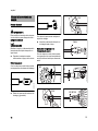 16
16
-
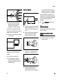 17
17
-
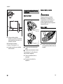 18
18
-
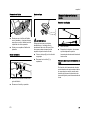 19
19
-
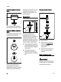 20
20
-
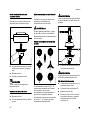 21
21
-
 22
22
-
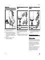 23
23
-
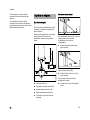 24
24
-
 25
25
-
 26
26
-
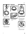 27
27
-
 28
28
-
 29
29
-
 30
30
-
 31
31
-
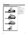 32
32
-
 33
33
-
 34
34
-
 35
35
-
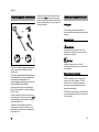 36
36
-
 37
37
-
 38
38
-
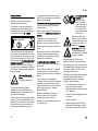 39
39
-
 40
40
-
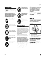 41
41
-
 42
42
-
 43
43
-
 44
44
-
 45
45
-
 46
46
-
 47
47
-
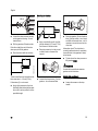 48
48
-
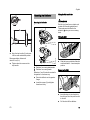 49
49
-
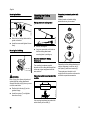 50
50
-
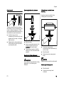 51
51
-
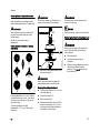 52
52
-
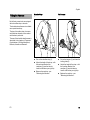 53
53
-
 54
54
-
 55
55
-
 56
56
-
 57
57
-
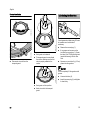 58
58
-
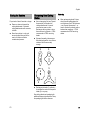 59
59
-
 60
60
-
 61
61
-
 62
62
-
 63
63
-
 64
64
-
 65
65
-
 66
66
-
 67
67
-
 68
68


STIHL FS Manual de usuario
- Categoría
- Podadoras de césped
- Tipo
- Manual de usuario
en otros idiomas
- English: STIHL FS User manual
Artículos relacionados
-
STIHL FS-KM Manual de usuario
-
-
-
-
-
STIHL FH Manual de usuario
-
-
-
-