
REV 001A
High
Quality
Nautical
Equipment
EBSN
EBSN 10
EBSN 15
EBSN 20
Manuale di installazione ed uso
INTERRUTTORE ELETTRONICO PER LA POMPA DI SENTINA
Manual for use and installation
ELECTRONIC SWITCH THE BILGE PUMP
Mode d’emploi et d’installation
INTERRUPTEUR ELECTRONIQUE POUR LA POMPE DE CALE
Installations- und Benutzerhandbuch
ELEKTRONISCHER SCHALTER FÜR DIE BILGENPUMPE
Manual de instalación y uso
INTERRUPTOR ELECTRÓNICO PARA LA BOMBA DE ACHIQUE
IT
GB
FR
DE
ES


3
EBSN 10-15-20 - REV001A
Pag. 4 Caratteristiche - installazione
Pag. 5 Installazione
Pag. 6 Funzionamento - Segnalazioni
Pag. 7 Manutenzione - Dati tecnici
INDICE
Pag. 8 Characteristics - Installation
Pag. 9 Installation
Pag. 10 Operating - Notification signs
Pag. 11 Maintenance - Technical data
Pag. 12 Caractéristiques - Installation
Pag. 13 Installation
Pag. 14 Fonctionnement - Signalisations
Pag. 15 Entretien - Caractéristiques techniques
SOMMAIRE
SEITE 16 Eigenschaften - Installation
S
EITE 17 Installation
S
EITE 18 Betrieb - Meldungen
S
EITE 19 Wartung - Technische daten
INHALTSANGABE
PÁG. 20 Características - Instalación
P
ÁG. 21 Instalación
P
ÁG. 22 Funcionamiento - Señalaciones
P
ÁG. 23 Mantenimiento - Especificaciones técnicas
INDICE
INDEX
IT
GB
FR
DE
ES

4
IT
EBSN 10-15-20 - REV001A
INTERRUTTORE ELETTRONICO PER LA POMPA DI SENTINA
Questo interruttore elettronico permette di azionare la pompa di sentina in presenza d’acqua.
Gli importanti vantaggi che l’EBSN offre sono:
• Funzionamento gestito da microcontrollore.
• Filtro digitale evoluto per discriminare la presenza dell’acqua.
• Range esteso di alimentazione.
• Indicazione remota dello stato di funzionamento tramite led o pannello remoto (opzionali).
• Possibilità di attivazione remota manuale della pompa tramite pulsante o pannello remoto (opzionali).
• Segnalazione attivazione prolungata della pompa di sentina (se installato led o pannello remoto).
• Protezione contro l’eccessivo scaricamento della batteria.
• Ritardo nell’attivazione e disattivazione per evitare false attivazioni e disattivazioni dovute al rollìo della
barca.
• Funzionamento in un ampio intervallo di temperatura ambiente.
• Involucro resinato e a tenuta stagna.
• Facilità di installazione.
INSTALLAZIONE
PRIMA DI UTILIZZARE L’EBSN LEGGERE ATTENTAMENTE IL PRESENTE MANUALE D’USO.
IN CASO DI DUBBI CONTATTARE IL RIVENDITORE O IL SERVIZIO CLIENTI QUICK
®
.
L’interruttore elettronico di sentina Quick
®
è stato progettato e realizzato per gli scopi descritti in questo
manuale d’uso. La società Quick
®
non si assume alcuna responsabilità per danni diretti o indiretti causati
da un uso improprio dell’apparecchio, da un’errata installazione o da possibili errori presenti in questo
manuale.
LA MANOMISSIONE DELL’EBSN DA PARTE DI PERSONALE NON AUTORIZZATO FA DECADERE
LA GARANZIA.
LA CONFEZIONE CONTIENE: EBSN - il presente manuale d’uso.
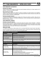
INSTALLAZIONE INTERRUTTORE ELETTRONICO DI SENTINA EBSN
Installare un EBSN appropriato in relazione all’assorbimento in corrente della pompa in condizioni di lavoro.
Installare l’EBSN in posizione verticale con il cavo di alimentazione rivolto verso l’alto e fissarlo alla parete
con due viti tramite le due asole laterali. Quest’ultime permettono una corretta regolazione dell’altezza
dei sensori rispetto al pescaggio della pompa. Regolare questa altezza in modo che, durante i 20 secondi
di ritardo della disattivazione della pompa, avvenga un completo svuotamento del vano.
ATTENZIONE: se l’EBSN viene fissato su pareti metalliche o elettricamente conduttive, particolare
attenzione deve essere posta alle viti di fissaggio (ed eventuali rondelle/squadrette) che devono
essere di materiale non elettricamente conduttivo.
CARATTERISTICHE - INSTALLAZIONE

5
INSTALLAZIONE
IT
EBSN 10-15-20 - REV001A
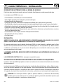
COLLEGAMENTO ELETTRICO
• Alimentare l’EBSN solo dopo aver effettuato e verificato l’esattezza di tutti i collegamenti elettrici.
• Inserire un fusibile rapido sulla linea di alimentazione di valore adeguato all’assorbimento della pompa di
sentina.
• Le giunzioni tra i cavi di uscita dell’EBSN e l’impianto elettrico devono essere a tenuta stagna oppure
realizzate all’interno di un contenitore stagno. Il grado di tenuta stagna (codice IP) deve essere scelto in
relazione all’ambiente di installazione.
• L’installazione del pulsante è subordinata all’installazione del led (opzionali).
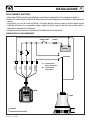
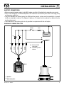
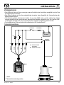
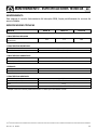
SCHEMA TIPICO DI COLLEGAMENTO
EBSN
POMPA
BATTERIA
FUSIBILEINTERRUTTORE
A
B
DEVIATORE
MARRONE
BLU
GRIGIO
NERO
ROSSO
(1)
Opzionali
(2)
Giunzioni a tenuta stagna
(2)
(1)
(2) (2)(2)(2)
(1)
A
= Funzionamento
diretto della pompa
B
= Funzionamento
tramite EBSN

6
IT
EBSN 10-15-20 - REV001A
SEGNALAZIONI DI FUNZIONAMENTO
STATO LED DESCRIZIONE
Il led è spento Non è presente la tensione di alimentazione.
Il led lampeggia lentamente Assenza di acqua e pompa disattivata.
Il led è quasi sempre acceso
con breve spegnimento
Presenza di acqua e pompa attivata.
Il led è sempre acceso
Funzionamento manuale tramite pulsante e pompa attivata
anche in assenza di acqua (durata massima 8 minuti).
Il led lampeggia velocemente Ritardo di attivazione e disattivazione.
ALTRE SEGNALAZIONI
STATO LED DESCRIZIONE
Il led mostra due
lampeggi veloci
Funzione salva batteria. Se l’alimentazione è inferiore a 9Vdc per gli impianti a 12Vdc oppure
se è compresa tra i 15-20Vdc per gli impianti a 24 Vdc, l’EBSN non attiverà la pompa. Control-
lare lo stato di carica delle batterie e il corretto dimensionamento dei cavi di alimentazione.
Il led mostra tre
lampeggi veloci
Attivazione prolungata della pompa.
Il sensore continua a segnalare la presenza di acqua trascorsi 8 minuti dall’attivazione.
Questa segnalazione potrebbe indicare:
• un normale comportamento del sistema
• un problema legato al corretto funzionamento della pompa
• la necessità di effettuare manutenzione all’ EBSN
• prolungata presenza di acqua nel luogo dove è installato l’EBSN
SEGNALAZIONI
Le seguenti segnalazioni sono presenti solo se si installa il led o il pannello remoto (opzionali).
Una volta collegata l’alimentazione il led si accenderà per 2 secondi in maniera continuativa per poi indicare
la condizione di funzionamento descritta nella seguente tabella:
FUNZIONAMENTO AUTOMATICO
Attivazione pompa
Quando l’acqua entra in contatto con entrambi i sensori in maniera continuativa, per un periodo superiore
ai 5 secondi, sarà attivata la pompa di sentina.
Disattivazione pompa
Quando uno o entrambi i sensori non si trovano più a contatto con l’acqua, per un periodo superiore ai 5
secondi, partirà un ritardo di 15 secondi sulla disattivazione della pompa. Trascorso questo ritardo la pompa
sarà disattivata.
Funzione salva batteria
Se la tensione di alimentazione scende sotto i 9Vdc (per impianti a 12Vdc) oppure è compresa tra i 15Vdc e
i 20Vdc (per impianti a 24Vdc) l’EBSN non permetterà l’attivazione della pompa di sentina.
FUNZIONAMENTO MANUALE
Attivazione manuale pompa
Il pulsante (opzionale) permette di attivare la pompa di sentina in maniera manuale. Premendolo e rila-
sciandolo per un tempo superiore a 1 secondo attiverà la pompa di sentina. Allo stesso modo se ripremuto
verrà disattivata. Dopo 8 minuti di funzionamento continuativo la pompa sarà automaticamente disattivata
e l’EBSN ritornerà in modalità automatica.
FUNZIONAMENTO - SEGNALAZIONI

7
IT
EBSN 10-15-20 - REV001A
QUICK
®
SI RISERVA IL DIRITTO DI APPORTARE MODIFICHE ALLE CARATTERISTICHE TECNICHE DELL’APPARECCHIO E AL CONTENUTO DI QUESTO MANUALE SENZA ALCUN PREAVVISO.
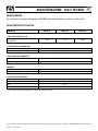
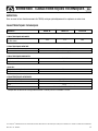
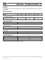
MODELLO EBSN 10 EBSN 15 EBSN 20
CARATTERISTICHE DI USCITA
Portata in corrente dei contatti
del relè (Max)
10 A 15 A 20 A
9 ÷ 31 Vdc
7,5 mA (Valore tipico)
CARATTERISTICHE DI INGRESSO
Tensione di alimentazione
(1)
Assorbimento di corrente a riposo
5 sec
20 sec
GENERALI
Ritardo all’attivazione
Ritardo alla disattivazione
da - 15 a + 70 °C
IP68
CARATTERISTICHE AMBIENTALI
Temperatura operativa
Grado di protezione
(1)
Esclusa zona funzione salva batteria 15-20Vdc per impianti a 24Vdc.
MANUTENZIONE
Per assicurare il regolare funzionamento dell’EBSN pulire periodicamente i sensori in acciaio inox.
CARATTERISTICHE TECNICHE
Nylon
75 x 83 x 38 mm
415 g
EN 60945 - FCC Part 15 Rules 47
CARATTERISTICHE GENERALI
Materiale contenitore
Dimensioni (L x A x P)
Peso
Classe EMC
MANUTENZIONE - DATI TECNICI

8
GB
EBSN 10-15-20 - REV001A
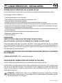
ELECTRONIC SWITCH FOR THE BILGE PUMP
This electronic switch permits the bilge pump to be switched on in the presence of water.
The advantages offered by the EBSN are:
• Operation managed by microcontroller.
• Advanced digital filter to distinguish the presence of water.
• Extended power supply range.
• Remote indication of operation status by led or remote control panel (optional).
• Manual remote pump switch-on by button or remote control panel (optional).
• Signal for prolonged bilge pump switch on (if led or remote control panel is installed).
• Protection against excessive battery rundown.
• Switch-on/switch-off delay to avoid false switch-on/switch-off cycling of the pump caused by the roll of
the boat.
• Functioning over a wide range of environmental temperatures.
• Resin-coated watertight casing.
• Easy installation.
INSTALLATION
BEFORE USING THE EBSN, READ THIS INSTRUCTION MANUAL CAREFULLY. IF IN DOUBT, CONTACT
YOUR NEAREST QUICK
®
RETAILER OR CUSTOMER SERVICE.
QUICK
®
electronic switch for the bilge pump has been designed and constructed for the purposes descri-
bed in this instruction manual. The Quick
®
company shall accept no responsibility for direct or indirect
damages caused by improper use of the instrument, or by incorrect installation or by possible errors in
this manual.
ANY TAMPERING WITH THE EBSN BY UNAUTHORIZED PERSONS WILL VOID THE GUARANTEE.
THE PACKAGE CONTAINS: EBSN - user's manual.
INSTALLATION OF THE EBSN ELECTRONIC SWITCH FOR BILGE PUMPS
Install the right EBSN for the maximum current rating of the pump under work conditions.
Install the EBSN in vertical position with the power supply cable facing upwards and then fasten it to the
support by screwing two screws into the two lateral slots. These two slots permit the correct adjustment
of the sensors’ height as regards the draught of the pump. Adjust this height in such way that a complete
drainage of the compartment occurs during the 20 seconds of pump disabling delay.
WARNING: if the EBSN must be fastened to electrically conductive metal walls, particular attention
must be paid to the fastening screws (and any washers/brackets used), which must be made in
non-electrically conductive material.
CHARACTERISTICS - INSTALLATION

9
INSTALLATION
GB
EBSN 10-15-20 - REV001A
ELECTRIC CONNECTIONS
• Before connecting power supply to the EBSN, make sure that all the electrical connections are correct.
• Insert a fast-acting fuse of a value adequate to the maximum current absorption value of the bilge pump
on the power supply line.
• The joints between the cables leaving the ESBN and the electric system must be watertight or housed
inside an watertight container. The degree of tightness (IP rating) must be selected as required by the
work envinronment.
• The installation of the button option is only possible in conjunction with the Led option.
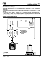
DIAGRAM OF CONNECTION TYPE
EBSN
PUMP
BATTERY
FUSESWITCH
SHUNTING
SWITCH
BROWN
BLUE
GREY
BLACK
RED
(1)
Optional
(2)
Watertight joints
(2) (2) (2)(2)(2)
A
B
(1)(1)
A
= Direct operation
of the pump
B
= operation by means
of EBSN

10
GB
EBSN 10-15-20 - REV001A
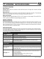
OPERATING STATUS
LED STATE DESCRIPTION
The led is off No power supply voltage is present
The led shows slow flashes Absence of water and pump switched off.
The led is almost always lit up
and switches off only briefly
Presence of water and pump is switched on.
The led is always lit up
Manual operation by button and pump switched on even in the absence of water
(8 minute maximum duration).
Rapidly flashing led Switch-on or switch-off delay.
OTHER SIGNALS
LED STATE DESCRIPTION
The led shows two
quick flashes
Battery save function. Whenever the power supply falls below 9V DC (for 12V DC systems)
or is in the range of 15V and 20V DC (for 24V DC systems), the EBSN will not permit bilge
pump switch-on. Check both the level of charge of the batteries and the correct sizing of
the power supply cables.
The led shows three
quick flashes
Prolonged pump working condition.
The sensor will continue signalling the presence of water for 8 minutes after switch-on.
This signal may indicate:
• normal system behaviour
• a problem linked to the correct working condition of the pump
• the need to service the EBSN
• prolonged presence of water where the EBSN is installed
NOTIFICATION SIGNS
The following signals are provided only if the led or the remote control panel has been installed (optional).
Once power supply has been connected, the led will light up for 2 seconds continuously in order to indicate
the operating status described in the table below:
AUTOMATIC OPERATION
Pump switch-on
Whenever water comes into continuous contact with both sensors for longer than 5 seconds, the bilge
pump switches on.
Pump switch-off
When one or both sensors are no longer in contact with water for longer than 5 seconds, a 15 second pump
switch-off period will begin. After this period has elapsed, the pump will switch off.
Battery save function
Whenever the power supply falls below 9V DC (for 12V DC systems) or is in the range of 15V and 20V DC (for
24V DC systems), the EBSN will not permit bilge pump switch-on.
MANUAL OPERATION
Manual pump switch-on
This button (optional) permits the bilge pump to be switched on manually. Pressing this button for more
than 1 second and then releasing it switches the bilge pump on. In the same way, if the button is pressed
again, the pump will switch off. After 8 minutes of continuous operation, the pump switches off automati-
cally and the EBSN returns to automatic mode.
OPERATING - NOTIFICATION SIGNS

11
GB
EBSN 10-15-20 - REV001A
QUICK
®
RESERVES THE RIGHT TO MODIFY THE TECHNICAL CHARACTERISTICS OF THE EQUIPMENT AND THE CONTENTS OF THIS MANUAL WITHOUT PRIOR NOTICE.
MAINTENANCE
Clean the stainless steel sensors periodically in order to ensure the regular operation of the EBSN.
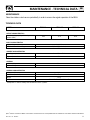
MODEL EBSN 10 EBSN 15 EBSN 20
OUTPUT CHARACTERISTICS
Current carrying capacity of the relay
contacts (Max)
10 A 15 A 20 A
9 ÷ 31 Vdc
7,5 mA (Typical value)
INPUT CHARACTERISTICS
Supply voltage
(1)
Current absorbed when idling
5 sec
20 sec
GENERAL
Switch-on delay
Switch-off delay
from - 15 to + 70 °C
IP68
AMBIENT CHARACTERISTICS
Operating temperature
Degree of protection
(1)
Except zone 15-20V DC battery save function for 24V DC systems.
TECHNICAL DATA
Nylon
75 x 83 x 38 mm
415 g
EN 60945 - FCC Part 15 Rules 47
GENERAL CHARACTERISTICS
Casing material
Dimensions (W x H x D)
Weight
EMC Class
MAINTENANCE - TECHNICAL DATA

12
FR
EBSN 10-15-20 - REV001A
INTERRUPTEUR ELECTRONIQUE POUR LA POMPE DE CALE
Cet interrupteur électronique permet de commander la pompe de cale en case de présence d’eau.
Les avantages qu’offrent l’EBSN sont:
• Fonctionnement géré par microcontrôleur
• Filtre numérique de pointe pour détecter la présence de l’eau.
• Gamme de tension d’alimentation étendue.
• Indication à distance du fonctionnement par led ou panneau à distance (en option).
• Possibilité d’enclenchement manuel à distance de la pompe par bouton ou panneau à distance (en option).
• Signalisation d’enclenchement prolongé de la pompe de cale (si équipé le led ou panneau à distance).
• Protection contre la décharge excessive de la batterie.
• Temporisation d’enclenchement et de déclenchement pour éviter un fonctionnement intempestif dus
au roulis du bateau.
• Fonctionnement dans une vaste gamme de température ambiante.
• Revêtement résiné étanche à l’eau.
• Facilité d’installation.
INSTALLATION
AVANT D’UTILISER LE EBSN, LIRE ATTENTIVEMENT CE MODE D’EMPLOI.
EN CAS DE DOUTES, CONTACTER LE REVENDEUR OU LE SERVICE CLIENTELE QUICK
®
.
L’interrupteur électronique pour la pompe de cale QUICK
®
a été conçu et fabriqué dans les buts spécifiés
par ce mode d’emploi. La firme Quick
®
n’assume aucune responsabilité en cas de dommages directs ou
indirects causés par une utilisation impropre de l’appareil, par une mauvaise installation ou par des er-
reurs éventuelles de ce mode d’emploi.
LA MANIPULATION DU EBSN PAR DU PERSONNEL NON AUTORISE IMPLIQUE LA DECHEANCE
DE LA GARANTIE.
L’EMBALLAGE CONTIENT: EBSN - manuel de l'utilisateur.
INSTALLATION DE L’INTERRUPTEUR ELECTRONIQUE DE CALE EBSN
Installer un EBSN approprié en fonction da courant absorbé par la pompe en service.
Installer l’EBSN en position verticale avec le câble d’alimentation vers le haut et le fixer au support avec
deux vis par les deux fentes latérales. Elles permettent un bon réglage de la hauteur des capteurs par
rapport au tirant d’eau de la pompe, le compartiment se vide complètement durant les 20 secondes de
temporisation avant arrêt.
ATTENTION: si l’EBSN est fixé à des cloisons métalliques conductrices d’électricité, il faut faire
particulièrement attention aux vis d’assemblage (et aux rondelles/équerres éventuelles), qui doi-
vent être en matière non conductrice.
CARACTÉRISTIQUES - INSTALLATION

13
INSTALLATION
FR
EBSN 10-15-20 - REV001A
BRANCHEMENT ELECTRIQUE
• Alimenter l’EBSN uniquement après avoir effectué et vérifié l’exactitude de tous les branchements
électriques.
• Introduire un fusible rapide sur la ligne d’alimentation de calibre adapté à la consommation de la pompe
de cale.
• Les jonctions entre les câbles de sortie de l’ESBN et l’installation électrique doivent être étanches à
l’eau ou placées à l’intérieur d’un boîtier étanche. Le degré d’étanchéité à l’eau (code IP) sera choisi en
fonction du milieu d’installation.
• L’installation du bouton est subordonnée à l’installation de la led (en option).
SCHEMA TYPIQUE DE BRANCHEMENT
EBSN
POMPE
BATTERIE
FUSIBLEINTERRUPTEUR
COMMUTATEUR
MARRON
BLEU
GRIS
NOIR
ROUGE
(1)
Optionnels
(2)
Jonctions étanche à l’eau
(2) (2) (2)(2)(2)
A
B
(1)(1)
A
= Fonctionnement
direct de la pompe
B
= Fonctionnement
par EBSN

14
FR
EBSN 10-15-20 - REV001A
SIGNALISATIONS DE FONCTIONNEMENT
MODE LED DESCRIPTION
La led est éteint Il n’y a pas de courant d’alimentation
La led clignote lentement Absence d’eau et pompe déclenchée
La led est presque toujours al-
lumé avec un bref clignotement
Présence d’eau et pompe enclenchée.
La led est toujours allumé
Fonctionnement manuel par bouton et pompe enclenchée même en présence d’eau
(durée maximale 8 minutes).
La led clignote rapidement Retard d’enclenchement et déclenchement
AUTRES SIGNALISATIONS
MODE LED DESCRIPTION
La led clignote rapidement
à deux reprises
Fonction de sauvegarde de la batterie. Si l’alimentation est inférieure à 9 Vdc pour les
installations à 12 Vdc ou si elle est comprise entre 15 - 20 Vdc pour les installations à 24 Vdc,
l’EBSN n’enclenchera pas la pompe. Contrôler la charge des batteries et le juste dimension-
nement des câbles d’alimentation.
La led clignote rapidement
à trois reprises
Enclenchement prolongé de la pompe
Le capteur continuera à signaler la présence d’eau après 8 minutes d’enclenchement.
Ce clignotement pourrait indiquer :
• Un comportement normal du système
• Un problème lié au bon fonctionnement de la pompe
• L’EBSN a besoin de maintenance
• Une présence d’eau prolongée dans l’endroit où est installé l’EBSN.
SIGNALISATION
Les signalisations ci-dessous apparaissent uniquement si on installe la led ou le panneau à distance (en option).
Une fois sous tension, la led s’allumera durant 2 secondes en mode continu puis indiquera le fonctionne-
ment de la pompe, de la manière décrite dans le tableau ci-dessous:
FONCTIONNEMENT AUTOMATIQUE
Enclenchement de la pompe
Quand l’eau entre en contact avec les deux capteurs sans interruption durant plus de 5 secondes, la pompe
de cale s’enclenche.
Déclenchement de la pompe
Quand l’un ou les deux capteurs ne sont plus en contact avec l’eau durant plus de 5 secondes, la pompe
sera stoppée après 15 seconds.
Fonction de sauvegarde de la batterie
Si la tension d’alimentation descend sous les 9 Vdc (pour une installation de 12 Vdc) ou si elle est comprise
entre 15 Vdc et 20 Vdc (pour des installations de 24 Vdc), l’EBSN ne permettra pas l’enclenchement de la
pompe de cale.
FONCTIONNEMENT MANUEL
Enclenchement manuel de la pompe
Le bouton (en option) permet d’enclencher la pompe de cale en mode manuel. En l’enfonçant et le relâ-
chant durant plus d’1 seconde, la pompe de cale s’enclenche. De même, si on appuie à nouveau, elle sera
déclenchée. Après 8 minutes de fonctionnement continu, la pompe sera automatiquement déclenchée et
l’EBSN retournera en mode automatique.
FONCTIONNEMENT - SIGNALISATION

15
FR
EBSN 10-15-20 - REV001A
LA SOCIETÉ QUICK
®
SE RÉ SER VE LE DRO IT D’AP POR TER LES MO DI FI CA TIONS NÉ CES SA I RES A UX CA RAC TÉ RIS TI QUES TE CHNI QUES DE L’AP PA RE IL ET AU CON TE NU DE CE LI VRET SANS A VIS PRÉ A LA BLE.
MODÉLE
EBSN 10 EBSN 15 EBSN 20
CARACTERISTIQUES DE SORTIE
Charge des contacts
du relais (Max)
10 A 15 A 20 A
9 ÷ 31 Vdc
7,5 mA (Valeur typique)
CARACTERISTIQUES D’ENTREE
Tension d'alimentation
(1)
Consommation en mode veille
5 sec
20 sec
generales
Temporisation à l’enclenchement
Temporisation au déclenchement
de - 15 à + 70 °C
IP68
CARACTERISTIQUES AMBIANTES
Température de service
Degré de protection
(1)
Excepté zone de fonction de sauvegarde de batterie 15-20 Vdc pour les installations à 24 Vdc.
ENTRETIEN
Pour assurer le bon fonctionnement de l’EBSN, nettoyer périodiquement les capteurs en acier inox.
CARACTÉRISTIQUES TECHNIQUES
Nylon
75 x 83 x 38 mm
415 g
EN 60945 - FCC Part 15 Rules 47
CARACTERISTIQUES GENERALES
Matière du boîtier
Dimensions (L x H x P)
Poids
Classe EMC
ENTRETIEN - CARACTÉRISTIQUES TECHNIQUES

16
DE
EBSN 10-15-20 - REV001A
ELEKTRONISCHER SCHALTER FÜR DIE BILGENPUMPE
Mit Hilfe dieses elektronischen Schalters kann die Bilgenpumpe betätigt werden, wenn sich Wasser ange-
sammelt hat.
Die EBSN bieten folgende Vorteile:
• Betrieb über Mikrocontroller gesteuert
• Hochentwickelter Digitalfilter zur Erfassung von Wasser
• Großer Versorgungsbereich
• Fernanzeige des Betriebszustands über LED oder Fernbedienungsblende (Sonderzubehör)
• Möglichkeit zur manuellen Fernbedienung der Pumpe über Taster oder Fernbedienungsblende (Sonder-
zubehör)
• Meldung bei anhaltendem Betrieb der Bilgenpumpe (falls LED-Diode oder Fernbedienungsblende instal-
liert ist)
• Batterie-Tiefentladungsschutz
• Ein- und Ausschaltverzögerung, um falsches Ein- und Ausschalten bei Rollen des Bootes zu vermeiden
• Betrieb innerhalb eines breiten Umgebungstemperaturintervalls
• Wasserdichtes Harzgehäuse
• Leichte Installation
INSTALLATION
LESEN SIE DIESE GEBRAUCHSANWEISUNG VOR BENUTZUNG DES EBSN AUFMERKSAM DURCH.
WENN SIE ZWEIFEL HABEN, SETZEN SIE SICH MIT DEM VERKÄUFER ODER MIT DEM KUNDENSER-
VICE VON QUICK
®
IN VERBINDUNG.
Der elektronische Bilgenschalter Quick
®
wurde für die in dieser Gebrauchsanleitung beschriebenen Zwe-
cke entwickelt und produziert. Die Firma Quick übernimmt keine Verantwortung für Schäden, die direkt
oder indirekt durch die unangebrachte Nutzung des Geräts, durch eine falsche Installation oder mögliche
Fehler in diesem Gebrauchshandbuch verursacht wurden.
DAS ÖFFNEN DES EBSN DURCH NICHT ERMÄCHTIGTES PERSONAL HAT DEN VERFALL
DER GARANTIE ZUR FOLGE.
DIE PACKUNG ENTHÄLT: EBSN - Benutzerhandbuch.
INSTALLATION DES ELEKTRONISCHEN BILGENSCHALTERS EBSN
Einen geeigneten EBSN im Verhältnis zur Stromaufnahme der Pumpe unter Betriebsbedingungen installieren.
Den EBSN in vertikaler Position installieren, wobei das Stromkabel nach oben zeigt, und mit zwei Schrau-
ben die beiden Seitenschlitze an der Halterung befestigen. Die Schlitze ermöglichen die korrekte Höhenre-
gulierung der Sensoren hinsichtlich des Ansaugsystems der Pumpe. Die Höhe so einstellen, dass in den 20
Sekunden Ausschaltverzögerung der Pumpe der Raum vollständig leergepumpt wird.
ACHTUNG: Wird der EBSN auf Wänden aus Metall oder anderem elektrisch leitendem Material in-
stalliert, ist besonders darauf zu achten, dass die Befestigungsschrauben (und eventuell eingesetz-
te Unterlegscheiben/Winkelbeschläge) aus nicht elektrisch leitendem Material sind.
EIGENSCHAFTEN - INSTALLATION

17
INSTALLATION
DE
EBSN 10-15-20 - REV001A
STROMANSCHLUSS
• Den EBSN erst dann mit Strom versorgen, wenn alle elektrischen Anschlüsse ausgeführt und auf ihre
Richtigkeit überprüft wurden.
• Eine flinke Sicherung auf der Versorgungsleitung einsetzen, deren Kapazität der Stromaufnahme der
Bilgenpumpe entspricht.
• Die Verbindungsstellen zwischen den Kabeln, die aus dem ESBN treten, und der elektrischen Anlage
müssen wasserdicht oder innerhalb eines wasserdichten Behälters ausgeführt sein. Der Grad der Was-
serdichtigkeit (Schutzgrad IP) muss entsprechend der Installationsumgebung gewählt werden.
• Die Installation des Tasters erfordert die Installation der LED (Sonderzubehör).
TYPISCHER SCHALTPLAN
EBSN
POMPE
BATTERIE
SICHERUNGSCHALTER
WECHSEL-
SCHALTER
BRAUN
BLAU
GRAU
SCHWARZ
ROT
(1)
Zusatz
(2)
Wasserdichte Verbindungsstellen
(2) (2) (2)(2)(2)
A
B
(1)(1)
A
= Direkter Betrieb
der Pumpe
B
= Betrieb über EBSN

18
DE
EBSN 10-15-20 - REV001A
ANZEIGEN DES BETRIEBSZUSTANDS
ZUSTAND LED BESCHREIBUNG
Das LED leuchtet nicht Keine Versorgungsspannung
Das LED blinkt langsam Kein Wasser und Pumpe ausgeschaltet
Das LED leuchtet praktisch
ununterbrochen und erlischt
nur kurz
Wasser vorhanden und Pumpe eingeschaltet
Das LED leuchtet ununterbro-
chen
Manueller Betrieb über Schalter und Pumpe auch ohne Wasser eingeschaltet
(maximale Dauer 8 Minuten)
Il led lampeggia velocemente Ein- und Ausschaltverzögerung
SONSTIGE ANZEIGEN
ZUSTAND LED BESCHREIBUNG
Das LED blinkt zweimal
kurz auf
Funktion Batteriewächter. Wenn die Stromversorgung für 12 V DC Anlagen unter 9 V DC oder für
24 V DC Anlagen zwischen 15 V DC und 20 V DC liegt, schaltet der EBSN die Bilgenpumpe nicht ein.
Den Ladezustand der Batterie und die korrekte Bemessung der Versorgungskabel überprüfen.
Das LED blinkt dreimal
kurz auf
Anhaltendes Einschalten der Pumpe
Der Sensor meldet auch nach Ablauf von 8 Minuten ab dem Zeitpunkt des Einschaltens
weiterhin, dass Wasser vorhanden ist. Diese Meldung könnte Folgendes bedeuten:
• Normales Verhalten des Systems
• Problem im Zusammenhang mit den korrekten Betriebsbedingungen der Pumpe
• Erforderliche Wartung des EBSN
• Anhaltendes Vorkommen von Wasser am Installationsort des EBSN
STROMANSCHLUSS
Für folgende Anzeigen muss die LED oder eine Fernbedienungsblende installiert sein.
Sobald die Stromversorgung hergestellt ist, leuchtet das LED 2 Sekunden ununterbrochen und zeigt an-
schließend den Betriebszustand, wie in der folgenden Tabelle beschrieben:
AUTOMATISCHE INSTALLATION
Einschalten der Pumpe
Wenn beide Sensoren ununterbrochen und länger als 5 Sekunden mit Wasser in Berührung kommen, wird
die Bilgenpumpe eingeschaltet.
Ausschalten der Pumpe
Wenn einer oder beide Sensoren länger als 5 Sekunden nicht mehr mit Wasser in Berührung kommen,
schaltet sich die Pumpe nach einer Verzögerungszeit von 15 Sekunden aus.
Funktion Batteriewächter
Wenn die Versorgungsspannung unter 9 V DC (für 12 V DC Anlagen ) sinkt oder zwischen 15 V DC und 20 V
DC (für 24 V DC Anlagen) liegt, verhindert der EBSN das Einschalten der Bilgenpumpe.
MANUELLE INSTALLATION
Manuelles Einschalten der Pumpe
Der Taster (Sonderzubehör) ermöglicht es, die Bilgenpumpe manuell einzuschalten. Wird er länger als 1
Sekunde gedrückt und anschließend losgelassen, schaltet sich die Bilgenpumpe ein. Auf die gleiche Weise
wird sie wieder ausgeschaltet, wenn der Taster erneut gedrückt wird. Nach 8 Minuten Dauerbetrieb wird
die Pumpe automatisch ausgeschaltet, der EBSN kehrt in den Automatikmodus zurück.
BETRIEB - MELDUNGEN

19
DE
EBSN 10-15-20 - REV001A
QUICK
®
BE HÄLT SICH DAS RECHT AUF ÄN DE RUN GEN DER TECH NI SCHEN EI GEN SCHAF TEN DES GE RÄTS UND DES IN HALTS DIE SES HAND BUCHS OH NE VO RAN KÜN DI GUNG
VOR.
MODELL EBSN 10 EBSN 15 EBSN 20
AUSGANGSEIGENSCHAFTEN
Stromleistung der Relaiskontakte (Max) 10 A 15 A 20 A
9 ÷ 31 Vdc
7,5 mA (Typischer Wert)
EINGANGSEIGENSCHAFTEN
Versorgungsspannung
(1)
Ruhestromaufnahme
5 sec
20 sec
ALLGEMEINES
Einschaltverzögerung
Ausschaltverzögerung
von - 15 bis + 70 °C
IP68
RAUMEIGENSCHAFTEN
Betriebstemperatur
Schutzgrad
(1)
Außer Bereich 15-20 V DC Batteriewächter für 24 V DC Anlagen.
WARTUNG
In regelmäßigen Abständen die Edelstahlsensoren reinigen, um den einwandfreien Betrieb des EBSN zu
gewährleisten.
TECHNISCHE DATEN
Nylon
75 x 83 x 38 mm
415 g
EN 60945 - FCC Part 15 Rules 47
CARATTERISTICHE generali
Gehäusematerial
Abmessungen (LxHxT)
Gewicht
EMV - Klassifizierung
WARTUNG - TECHNISCHE DATEN

20
ES
EBSN 10-15-20 - REV001A
INTERRUPTOR ELECTRÓNICO PARA LA BOMBA DE ACHIQUE
Este interruptor electrónico permite accionar la bomba de achique en caso de presencia de agua.
Las ventajas que el EBSN ofrece son:
• Funcionamiento controlado por un microcontrolador.
• Filtro digital avanzado para distinguir la presencia del agua.
• Rango extendido de alimentación.
• Indicación remota del estado de funcionamiento mediante led o panel remoto (opcionales).
• Posibilidad de activación remota manual de la bomba mediante pulsador o panel remoto (opcionales).
• Señalización de activación prolongada de la bomba de achique (si está instalado el led o el panel remoto).
• Protección contra la descarga excesiva de la batería.
• Retardo en la activación y la desactivación, para evitar falsas activaciones y desactivaciones ocasiona-
das por el balanceo del barco.
• Funcionamiento en un amplio intervalo de temperatura ambiente.
• Revestimiento de resina y estanco.
• Fácil de instalar.
INSTALACIÓN
ANTES DE USAR EL EBSN, LEER ATENTAMENTE EL PRESENTE MANUAL DEL USUARIO.
EN CASO DE
DUDAS, CONTACTAR EL REVENDEDOR O EL SERVICIO DE CLIENTES QUICK
®
.
El interruptor electrónico para la bomba de achique QUICK
®
ha sido diseñado y realizado para los fines
descritos en el presente manual del usuario. La sociedad Quick
®
no se responsabiliza por daños directos
o indirectos, ocasionados por un uso incorrecto del aparato, por una instalación errónea o por posibles
errores presentes en este manual.
LA MANIPULACIÓN DEL EBSN POR PARTE DE PERSONAL NO AUTORIZADO HACE NULA LA
GARANTÍA.
LA CONFECCIÓN CONTIENE: EBSN - el presente manual del usuario.
INSTALACIÓN DEL INTERRUPTOR ELECTRÓNICO PARA BOMBA DE ACHIQUE EBSN
Instalar un interruptor EBSN apropiado en relación a la absorción de corriente de la bomba en condiciones
de funcionamiento.
Instalar el interruptor EBSN en posición vertical con el cable de alimentación hacia arriba, y fijarlo al sopor-
te con dos tornillos mediante los dos ojales laterales. Estos últimos permiten ajustar correctamente la al-
tura de los sensores respecto a la aspiración de la bomba. Ajustar esta altura de manera que, durante los
20 segundos de retardo de la desactivación de la bomba, se produzca un total vaciado del compartimiento.
ATENCIÓN: Si el interruptor EBSN es fijado en paredes metálicas y conductoras de electricidad,
se debe prestar mucha atención en los tornillos de fijación (y eventuales arandelas/soportes) que
deben ser de material no conductores de electricidad.
CARACTERÍSTICAS - INSTALACIÓN

21
INSTALACIÓN
ES
EBSN 10-15-20 - REV001A
CONEXIÓN ELÉCTRICA
• Alimentar el interruptor EBSN sólo después de haber comprobado que todas las conexiones eléctricas
hayan sido correctamente realizadas.
• Introducir un fusible rápido en la línea de alimentación de valor adecuado a la absorción de la bomba de achique.
• Las uniones entre los cables de salida del interruptor EBSN y la instalación eléctrica deben ser estancas
o bien se deben realizar dentro de un contenedor estanco. El grado de estanqueidad (código IP) se debe
elegir con relación al ambiente de trabajo.
• La instalación del pulsador está sujeta a la instalación del led (opcional).
ESQUEMA TÍPICO DE CONEXIÓN
EBSN
BOMBA
BATERÍA
FUSIBLEINTERRUPTOR
INTERRUPTOR
DE DERIVACIÓN
MARRON
AZUL
GRIS
NEGRO
ROJO
(1)
Opcionales
(2)
Conexiones estancas
(2) (2) (2)(2)(2)
A
B
(1)(1)
A
= Funcionamiento
directo de la bomba
B
= Funcionamiento
tr
á
mite EBSN

22
ES
EBSN 10-15-20 - REV001A
SEÑALIZACIONES DE FUNCIONAMIENTO
ESTADO LED DESCRIPCIÓN
El led está apagado No hay tensión de alimentación.
El led parpadea lentamente Ausencia de agua y bomba desactivada.
El led está siempre encendido
con breve apagado
Presencia de agua y bomba activada.
El led está siempre encendido
Funcionamiento manual mediante pulsador y bomba activada incluso en caso de ausencia
de agua (duración máxima 8 minutos).
El led relampaguea velozmente Retardo activación y desactivación.
OTRAS SEÑALIZACIONES
ESTADO LED DESCRIPCIÓN
El led realiza dos
parpadeos rápidos
Función protección de batería. Si la alimentación es inferior a 9Vdc para las instalaciones a
12Vdc o bien si está comprendida entre los 15-20Vdc para las instalaciones a 24Vdc, el inter-
ruptor EBSN no activará la bomba. Controlar el estado de carga de las baterías y el correcto
dimensionamiento de los cables de alimentación.
El led realiza tres
parpadeos rápidos
Funcionamiento prolongado de la bomba.
El sensor continuará señalando la presencia de agua transcurridos 8 minutos de la activación.
Esta señalización podría indicar:
• Un comportamiento normal del sistema
• Un problema vinculado con el correcto funcionamiento de la bomba
• La necesidad de mantenimiento en el interruptor EBSN
• La prolongada presencia de agua en el lugar donde está instalado el interruptor EBSN.
SEÑALIZACIONES
Las siguientes señalizaciones están presentes sólo si se instala el diodo led o el panel remoto (opcionales).
Una vez conectada la alimentación, el led se encenderá durante 2 segundos de manera continua para luego
indicar la condición de funcionamiento descrita en la siguiente tabla:
FUNCIONAMIENTO AUTOMÁTICO
Activación de la bomba
Cuando el agua entra en contacto con ambos sensores de manera continua, por un lapso superior a los 5
segundos, se activará la bomba de achique.
Desactivación de la bomba
Cuando uno o ambos sensores ya no están en contacto con el agua, por un lapso superior a los 5 segundos,
iniciará un lapso de retardo de 15 segundos para la desactivación de la bomba. Una vez transcurrido este
periodo de retardo, la bomba será desactivada.
Función protección de batería
Si la tensión de alimentación desciende por debajo de los 9Vdc (para instalación a 12Vdc) o bien está com-
prendida entre los 15Vdc y los 20Vdc (para instalaciones a 24Vdc) el interruptor EBSN no permitirá que la
bomba de achique se active.
FUNCIONAMIENTO MANUAL
Activación manual de la bomba
El pulsador (opcional) permite activar la bomba de achique de manera manual. Pulsándolo y soltándolo
durante un tiempo superior a 1 segundo, activará la bomba de achique. De la misma manera, si se lo pulsa
nuevamente la desactivará. Después de 8 minutos de funcionamiento continuo, la bomba será desactivada
automáticamente y el interruptor EBSN volverá al modo automático.
FUNCIONAMIENTO - SEÑALIZACIONES

23
ES
EBSN 10-15-20 - REV001A
QUICK
®
SE RE SER VA EL DE RE CHO DE A POR TAR MO DI FI CA CIO NES EN LAS CA RAC TE RÍS TI CAS TÉC NI CAS DEL A PA RA TO Y EN EL CON TE NI DO DE ES TE MA NUAL SIN O BLI GA CIÓN DE A VI SAR PRE VIA MEN TE.
MODELO EBSN 10 EBSN 15 EBSN 20
CARACTERÍSTICAS DE SALIDA
Capacidad de corriente de los contactos
del relé (Máx.)
10 A 15 A 20 A
9 ÷ 31 Vdc
7,5 mA (Valor típico)
CARACTERISTÍCAS DE ENTRADA
Tensión de alimentación
(1)
Absorción de corriente en reposo
5 sec
20 sec
GENERALES
Retardo para la activación
Retardo para la desactivación
de - 15 a + 70 °C
IP68
CARACTERÍSTICAS AMBIENTALES
Temperatura de trabajo
Grado de protección
(1)
Excepto la zona de la función protección de batería 15-20Vdc para instalaciones a 24Vdc.
MANTENIMIENTO
Para asegurar el correcto funcionamiento del interruptor EBSN, limpiar periódicamente los sensores de
acero inoxidable.
ESPECIFICACIONES TÉCNICAS
Nylon
75 x 83 x 38 mm
415 g
EN 60945 - FCC Part 15 Rules 47
CARACTERÍSTICAS GENERALES
Material del contenedor
Dimensiones (L x A x P)
Peso
Clase EMC
MANTENIMIENTO - ESPECIFICACIONES TÉCNICAS

EBSN 10-15-20 - REV001A
24
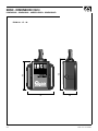
EBSN - DIMENSIONI (mm)
DIMENSIONS - DIMENSIONS - ABMESSUNGEN - DIMENSIONES
83
75 38
90
EBSN 10 - 15 - 20

NOTE
NOTES - NOTES - NOTIZEN - NOTAS

NOTE
NOTES - NOTES - NOTIZEN - NOTAS


QUICK
®
SRL - Via Piangipane, 120/A - 48100 Piangipane (RAVENNA) - ITALY
Tel. +39.0544.415061 - Fax +39.0544.415047
www.quickitaly.com - E-mail: quick@quickitaly.com
R001A
Codice e numero seriale del prodotto
Product code and serial number
Code et numéro de série du produit
Code- und Seriennummer des Produkts
Código y número de serie del producto
GB
FR
DE
IT
ES
Transcripción de documentos
REV 001A High Quality Nautical Equipment EBSN EBSN 10 EBSN 15 EBSN 20 IT Manuale di installazione ed uso INTERRUTTORE ELETTRONICO PER LA POMPA DI SENTINA GB Manual for use and installation ELECTRONIC SWITCH THE BILGE PUMP FR Mode d’emploi et d’installation INTERRUPTEUR ELECTRONIQUE POUR LA POMPE DE CALE DE Installations- und Benutzerhandbuch ELEKTRONISCHER SCHALTER FÜR DIE BILGENPUMPE ES Manual de instalación y uso INTERRUPTOR ELECTRÓNICO PARA LA BOMBA DE ACHIQUE IT INDICE Pag. 4 Pag. 5 Pag. 6 Pag. 7 Caratteristiche - installazione Installazione Funzionamento - Segnalazioni Manutenzione - Dati tecnici GB INDEX Pag. 8 Pag. 9 Pag. 10 Pag. 11 Characteristics - Installation Installation Operating - Notification signs Maintenance - Technical data FR SOMMAIRE Pag. 12 Pag. 13 Pag. 14 Pag. 15 Caractéristiques - Installation Installation Fonctionnement - Signalisations Entretien - Caractéristiques techniques DE INHALTSANGABE SEITE 16 SEITE 17 SEITE 18 SEITE 19 Eigenschaften - Installation Installation Betrieb - Meldungen Wartung - Technische daten ES INDICE PÁG. 20 PÁG. 21 PÁG. 22 PÁG. 23 Características - Instalación Instalación Funcionamiento - Señalaciones Mantenimiento - Especificaciones técnicas EBSN 10-15-20 - REV001A 3 IT CARATTERISTICHE - INSTALLAZIONE INTERRUTTORE ELETTRONICO PER LA POMPA DI SENTINA Questo interruttore elettronico permette di azionare la pompa di sentina in presenza d’acqua. Gli importanti vantaggi che l’EBSN offre sono: • Funzionamento gestito da microcontrollore. • Filtro digitale evoluto per discriminare la presenza dell’acqua. • Range esteso di alimentazione. • Indicazione remota dello stato di funzionamento tramite led o pannello remoto (opzionali). • Possibilità di attivazione remota manuale della pompa tramite pulsante o pannello remoto (opzionali). • Segnalazione attivazione prolungata della pompa di sentina (se installato led o pannello remoto). • Protezione contro l’eccessivo scaricamento della batteria. • Ritardo nell’attivazione e disattivazione per evitare false attivazioni e disattivazioni dovute al rollìo della barca. • Funzionamento in un ampio intervallo di temperatura ambiente. • Involucro resinato e a tenuta stagna. • Facilità di installazione. INSTALLAZIONE PRIMA DI UTILIZZARE L’EBSN LEGGERE ATTENTAMENTE IL PRESENTE MANUALE D’USO. IN CASO DI DUBBI CONTATTARE IL RIVENDITORE O IL SERVIZIO CLIENTI QUICK®. L’interruttore elettronico di sentina Quick® è stato progettato e realizzato per gli scopi descritti in questo manuale d’uso. La società Quick® non si assume alcuna responsabilità per danni diretti o indiretti causati da un uso improprio dell’apparecchio, da un’errata installazione o da possibili errori presenti in questo manuale. LA MANOMISSIONE DELL’EBSN DA PARTE DI PERSONALE NON AUTORIZZATO FA DECADERE LA GARANZIA. LA CONFEZIONE CONTIENE: EBSN - il presente manuale d’uso. INSTALLAZIONE INTERRUTTORE ELETTRONICO DI SENTINA EBSN Installare un EBSN appropriato in relazione all’assorbimento in corrente della pompa in condizioni di lavoro. Installare l’EBSN in posizione verticale con il cavo di alimentazione rivolto verso l’alto e fissarlo alla parete con due viti tramite le due asole laterali. Quest’ultime permettono una corretta regolazione dell’altezza dei sensori rispetto al pescaggio della pompa. Regolare questa altezza in modo che, durante i 20 secondi di ritardo della disattivazione della pompa, avvenga un completo svuotamento del vano. ATTENZIONE: se l’EBSN viene fissato su pareti metalliche o elettricamente conduttive, particolare attenzione deve essere posta alle viti di fissaggio (ed eventuali rondelle/squadrette) che devono essere di materiale non elettricamente conduttivo. 4 EBSN 10-15-20 - REV001A INSTALLAZIONE IT COLLEGAMENTO ELETTRICO • Alimentare l’EBSN solo dopo aver effettuato e verificato l’esattezza di tutti i collegamenti elettrici. • Inserire un fusibile rapido sulla linea di alimentazione di valore adeguato all’assorbimento della pompa di sentina. • Le giunzioni tra i cavi di uscita dell’EBSN e l’impianto elettrico devono essere a tenuta stagna oppure realizzate all’interno di un contenitore stagno. Il grado di tenuta stagna (codice IP) deve essere scelto in relazione all’ambiente di installazione. • L’installazione del pulsante è subordinata all’installazione del led (opzionali). SCHEMA TIPICO DI COLLEGAMENTO INTERRUTTORE FUSIBILE BATTERIA (1) (1) A DEVIATORE (2) (2) (2) (2) B (2) MARRONE ROSSO GRIGIO BLU NERO A = Funzionamento diretto della pompa B = Funzionamento tramite EBSN EBSN POMPA (1) Opzionali (2) Giunzioni a tenuta stagna EBSN 10-15-20 - REV001A 5 IT FUNZIONAMENTO - SEGNALAZIONI FUNZIONAMENTO AUTOMATICO Attivazione pompa Quando l’acqua entra in contatto con entrambi i sensori in maniera continuativa, per un periodo superiore ai 5 secondi, sarà attivata la pompa di sentina. Disattivazione pompa Quando uno o entrambi i sensori non si trovano più a contatto con l’acqua, per un periodo superiore ai 5 secondi, partirà un ritardo di 15 secondi sulla disattivazione della pompa. Trascorso questo ritardo la pompa sarà disattivata. Funzione salva batteria Se la tensione di alimentazione scende sotto i 9Vdc (per impianti a 12Vdc) oppure è compresa tra i 15Vdc e i 20Vdc (per impianti a 24Vdc) l’EBSN non permetterà l’attivazione della pompa di sentina. FUNZIONAMENTO MANUALE Attivazione manuale pompa Il pulsante (opzionale) permette di attivare la pompa di sentina in maniera manuale. Premendolo e rilasciandolo per un tempo superiore a 1 secondo attiverà la pompa di sentina. Allo stesso modo se ripremuto verrà disattivata. Dopo 8 minuti di funzionamento continuativo la pompa sarà automaticamente disattivata e l’EBSN ritornerà in modalità automatica. SEGNALAZIONI Le seguenti segnalazioni sono presenti solo se si installa il led o il pannello remoto (opzionali). Una volta collegata l’alimentazione il led si accenderà per 2 secondi in maniera continuativa per poi indicare la condizione di funzionamento descritta nella seguente tabella: SEGNALAZIONI DI FUNZIONAMENTO STATO LED DESCRIZIONE Il led è spento Non è presente la tensione di alimentazione. Il led lampeggia lentamente Assenza di acqua e pompa disattivata. Il led è quasi sempre acceso con breve spegnimento Presenza di acqua e pompa attivata. Il led è sempre acceso Funzionamento manuale tramite pulsante e pompa attivata anche in assenza di acqua (durata massima 8 minuti). Il led lampeggia velocemente Ritardo di attivazione e disattivazione. ALTRE SEGNALAZIONI 6 STATO LED DESCRIZIONE Il led mostra due lampeggi veloci Funzione salva batteria. Se l’alimentazione è inferiore a 9Vdc per gli impianti a 12Vdc oppure se è compresa tra i 15-20Vdc per gli impianti a 24 Vdc, l’EBSN non attiverà la pompa. Controllare lo stato di carica delle batterie e il corretto dimensionamento dei cavi di alimentazione. Il led mostra tre lampeggi veloci Attivazione prolungata della pompa. Il sensore continua a segnalare la presenza di acqua trascorsi 8 minuti dall’attivazione. Questa segnalazione potrebbe indicare: • un normale comportamento del sistema • un problema legato al corretto funzionamento della pompa • la necessità di effettuare manutenzione all’ EBSN • prolungata presenza di acqua nel luogo dove è installato l’EBSN EBSN 10-15-20 - REV001A MANUTENZIONE - DATI TECNICI IT MANUTENZIONE Per assicurare il regolare funzionamento dell’EBSN pulire periodicamente i sensori in acciaio inox. CARATTERISTICHE TECNICHE MODELLO EBSN 10 EBSN 15 EBSN 20 10 A 15 A 20 A CARATTERISTICHE DI USCITA Portata in corrente dei contatti del relè (Max) CARATTERISTICHE DI INGRESSO Tensione di alimentazione (1) Assorbimento di corrente a riposo 9 ÷ 31 Vdc 7,5 mA (Valore tipico) CARATTERISTICHE AMBIENTALI Temperatura operativa da - 15 a + 70 °C Grado di protezione IP68 GENERALI Ritardo all’attivazione 5 sec Ritardo alla disattivazione 20 sec CARATTERISTICHE GENERALI Materiale contenitore Nylon Dimensioni (L x A x P) 75 x 83 x 38 mm Peso Classe EMC (1) 415 g EN 60945 - FCC Part 15 Rules 47 Esclusa zona funzione salva batteria 15-20Vdc per impianti a 24Vdc. QUICK® SI RISERVA IL DIRITTO DI APPORTARE MODIFICHE ALLE CARATTERISTICHE TECNICHE DELL’APPARECCHIO E AL CONTENUTO DI QUESTO MANUALE SENZA ALCUN PREAVVISO. EBSN 10-15-20 - REV001A 7 GB CHARACTERISTICS - INSTALLATION ELECTRONIC SWITCH FOR THE BILGE PUMP This electronic switch permits the bilge pump to be switched on in the presence of water. The advantages offered by the EBSN are: • • • • • • • • Operation managed by microcontroller. Advanced digital filter to distinguish the presence of water. Extended power supply range. Remote indication of operation status by led or remote control panel (optional). Manual remote pump switch-on by button or remote control panel (optional). Signal for prolonged bilge pump switch on (if led or remote control panel is installed). Protection against excessive battery rundown. Switch-on/switch-off delay to avoid false switch-on/switch-off cycling of the pump caused by the roll of the boat. • Functioning over a wide range of environmental temperatures. • Resin-coated watertight casing. • Easy installation. INSTALLATION BEFORE USING THE EBSN, READ THIS INSTRUCTION MANUAL CAREFULLY. IF IN DOUBT, CONTACT YOUR NEAREST QUICK® RETAILER OR CUSTOMER SERVICE. QUICK® electronic switch for the bilge pump has been designed and constructed for the purposes described in this instruction manual. The Quick® company shall accept no responsibility for direct or indirect damages caused by improper use of the instrument, or by incorrect installation or by possible errors in this manual. ANY TAMPERING WITH THE EBSN BY UNAUTHORIZED PERSONS WILL VOID THE GUARANTEE. THE PACKAGE CONTAINS: EBSN - user's manual. INSTALLATION OF THE EBSN ELECTRONIC SWITCH FOR BILGE PUMPS Install the right EBSN for the maximum current rating of the pump under work conditions. Install the EBSN in vertical position with the power supply cable facing upwards and then fasten it to the support by screwing two screws into the two lateral slots. These two slots permit the correct adjustment of the sensors’ height as regards the draught of the pump. Adjust this height in such way that a complete drainage of the compartment occurs during the 20 seconds of pump disabling delay. WARNING: if the EBSN must be fastened to electrically conductive metal walls, particular attention must be paid to the fastening screws (and any washers/brackets used), which must be made in non-electrically conductive material. 8 EBSN 10-15-20 - REV001A INSTALLATION GB ELECTRIC CONNECTIONS • Before connecting power supply to the EBSN, make sure that all the electrical connections are correct. • Insert a fast-acting fuse of a value adequate to the maximum current absorption value of the bilge pump on the power supply line. • The joints between the cables leaving the ESBN and the electric system must be watertight or housed inside an watertight container. The degree of tightness (IP rating) must be selected as required by the work envinronment. • The installation of the button option is only possible in conjunction with the Led option. DIAGRAM OF CONNECTION TYPE SWITCH FUSE BATTERY (1) (1) A SHUNTING SWITCH (2) (2) (2) (2) B (2) BROWN RED GREY BLUE BLACK A = Direct operation of the pump B = operation by means of EBSN EBSN PUMP (1) Optional (2) Watertight joints EBSN 10-15-20 - REV001A 9 GB OPERATING - NOTIFICATION SIGNS AUTOMATIC OPERATION Pump switch-on Whenever water comes into continuous contact with both sensors for longer than 5 seconds, the bilge pump switches on. Pump switch-off When one or both sensors are no longer in contact with water for longer than 5 seconds, a 15 second pump switch-off period will begin. After this period has elapsed, the pump will switch off. Battery save function Whenever the power supply falls below 9V DC (for 12V DC systems) or is in the range of 15V and 20V DC (for 24V DC systems), the EBSN will not permit bilge pump switch-on. MANUAL OPERATION Manual pump switch-on This button (optional) permits the bilge pump to be switched on manually. Pressing this button for more than 1 second and then releasing it switches the bilge pump on. In the same way, if the button is pressed again, the pump will switch off. After 8 minutes of continuous operation, the pump switches off automatically and the EBSN returns to automatic mode. NOTIFICATION SIGNS The following signals are provided only if the led or the remote control panel has been installed (optional). Once power supply has been connected, the led will light up for 2 seconds continuously in order to indicate the operating status described in the table below: OPERATING STATUS LED STATE DESCRIPTION The led is off No power supply voltage is present The led shows slow flashes Absence of water and pump switched off. The led is almost always lit up and switches off only briefly Presence of water and pump is switched on. The led is always lit up Manual operation by button and pump switched on even in the absence of water (8 minute maximum duration). Rapidly flashing led Switch-on or switch-off delay. OTHER SIGNALS LED STATE DESCRIPTION The led shows two quick flashes Battery save function. Whenever the power supply falls below 9V DC (for 12V DC systems) or is in the range of 15V and 20V DC (for 24V DC systems), the EBSN will not permit bilge pump switch-on. Check both the level of charge of the batteries and the correct sizing of the power supply cables. The led shows three quick flashes Prolonged pump working condition. The sensor will continue signalling the presence of water for 8 minutes after switch-on. This signal may indicate: • normal system behaviour • a problem linked to the correct working condition of the pump • the need to service the EBSN • prolonged presence of water where the EBSN is installed 10 EBSN 10-15-20 - REV001A MAINTENANCE - TECHNICAL DATA GB MAINTENANCE Clean the stainless steel sensors periodically in order to ensure the regular operation of the EBSN. TECHNICAL DATA MODEL EBSN 10 EBSN 15 EBSN 20 10 A 15 A 20 A OUTPUT CHARACTERISTICS Current carrying capacity of the relay contacts (Max) INPUT CHARACTERISTICS Supply voltage (1) Current absorbed when idling 9 ÷ 31 Vdc 7,5 mA (Typical value) AMBIENT CHARACTERISTICS Operating temperature from - 15 to + 70 °C Degree of protection IP68 GENERAL Switch-on delay 5 sec Switch-off delay 20 sec GENERAL CHARACTERISTICS Casing material Dimensions (W x H x D) Weight EMC Class (1) Nylon 75 x 83 x 38 mm 415 g EN 60945 - FCC Part 15 Rules 47 Except zone 15-20V DC battery save function for 24V DC systems. QUICK® RESERVES THE RIGHT TO MODIFY THE TECHNICAL CHARACTERISTICS OF THE EQUIPMENT AND THE CONTENTS OF THIS MANUAL WITHOUT PRIOR NOTICE. EBSN 10-15-20 - REV001A 11 FR CARACTÉRISTIQUES - INSTALLATION INTERRUPTEUR ELECTRONIQUE POUR LA POMPE DE CALE Cet interrupteur électronique permet de commander la pompe de cale en case de présence d’eau. Les avantages qu’offrent l’EBSN sont: • • • • • • • • Fonctionnement géré par microcontrôleur Filtre numérique de pointe pour détecter la présence de l’eau. Gamme de tension d’alimentation étendue. Indication à distance du fonctionnement par led ou panneau à distance (en option). Possibilité d’enclenchement manuel à distance de la pompe par bouton ou panneau à distance (en option). Signalisation d’enclenchement prolongé de la pompe de cale (si équipé le led ou panneau à distance). Protection contre la décharge excessive de la batterie. Temporisation d’enclenchement et de déclenchement pour éviter un fonctionnement intempestif dus au roulis du bateau. • Fonctionnement dans une vaste gamme de température ambiante. • Revêtement résiné étanche à l’eau. • Facilité d’installation. INSTALLATION AVANT D’UTILISER LE EBSN, LIRE ATTENTIVEMENT CE MODE D’EMPLOI. EN CAS DE DOUTES, CONTACTER LE REVENDEUR OU LE SERVICE CLIENTELE QUICK®. L’interrupteur électronique pour la pompe de cale QUICK® a été conçu et fabriqué dans les buts spécifiés par ce mode d’emploi. La firme Quick® n’assume aucune responsabilité en cas de dommages directs ou indirects causés par une utilisation impropre de l’appareil, par une mauvaise installation ou par des erreurs éventuelles de ce mode d’emploi. LA MANIPULATION DU EBSN PAR DU PERSONNEL NON AUTORISE IMPLIQUE LA DECHEANCE DE LA GARANTIE. L’EMBALLAGE CONTIENT: EBSN - manuel de l'utilisateur. INSTALLATION DE L’INTERRUPTEUR ELECTRONIQUE DE CALE EBSN Installer un EBSN approprié en fonction da courant absorbé par la pompe en service. Installer l’EBSN en position verticale avec le câble d’alimentation vers le haut et le fixer au support avec deux vis par les deux fentes latérales. Elles permettent un bon réglage de la hauteur des capteurs par rapport au tirant d’eau de la pompe, le compartiment se vide complètement durant les 20 secondes de temporisation avant arrêt. ATTENTION: si l’EBSN est fixé à des cloisons métalliques conductrices d’électricité, il faut faire particulièrement attention aux vis d’assemblage (et aux rondelles/équerres éventuelles), qui doivent être en matière non conductrice. 12 EBSN 10-15-20 - REV001A INSTALLATION FR BRANCHEMENT ELECTRIQUE • Alimenter l’EBSN uniquement après avoir effectué et vérifié l’exactitude de tous les branchements électriques. • Introduire un fusible rapide sur la ligne d’alimentation de calibre adapté à la consommation de la pompe de cale. • Les jonctions entre les câbles de sortie de l’ESBN et l’installation électrique doivent être étanches à l’eau ou placées à l’intérieur d’un boîtier étanche. Le degré d’étanchéité à l’eau (code IP) sera choisi en fonction du milieu d’installation. • L’installation du bouton est subordonnée à l’installation de la led (en option). SCHEMA TYPIQUE DE BRANCHEMENT INTERRUPTEUR FUSIBLE BATTERIE (1) (1) A COMMUTATEUR (2) (2) (2) (2) B (2) MARRON ROUGE GRIS BLEU NOIR A = Fonctionnement direct de la pompe B = Fonctionnement par EBSN EBSN POMPE (1) Optionnels (2) Jonctions étanche à l’eau EBSN 10-15-20 - REV001A 13 FR FONCTIONNEMENT - SIGNALISATION FONCTIONNEMENT AUTOMATIQUE Enclenchement de la pompe Quand l’eau entre en contact avec les deux capteurs sans interruption durant plus de 5 secondes, la pompe de cale s’enclenche. Déclenchement de la pompe Quand l’un ou les deux capteurs ne sont plus en contact avec l’eau durant plus de 5 secondes, la pompe sera stoppée après 15 seconds. Fonction de sauvegarde de la batterie Si la tension d’alimentation descend sous les 9 Vdc (pour une installation de 12 Vdc) ou si elle est comprise entre 15 Vdc et 20 Vdc (pour des installations de 24 Vdc), l’EBSN ne permettra pas l’enclenchement de la pompe de cale. FONCTIONNEMENT MANUEL Enclenchement manuel de la pompe Le bouton (en option) permet d’enclencher la pompe de cale en mode manuel. En l’enfonçant et le relâchant durant plus d’1 seconde, la pompe de cale s’enclenche. De même, si on appuie à nouveau, elle sera déclenchée. Après 8 minutes de fonctionnement continu, la pompe sera automatiquement déclenchée et l’EBSN retournera en mode automatique. SIGNALISATION Les signalisations ci-dessous apparaissent uniquement si on installe la led ou le panneau à distance (en option). Une fois sous tension, la led s’allumera durant 2 secondes en mode continu puis indiquera le fonctionnement de la pompe, de la manière décrite dans le tableau ci-dessous: SIGNALISATIONS DE FONCTIONNEMENT MODE LED DESCRIPTION La led est éteint Il n’y a pas de courant d’alimentation La led clignote lentement Absence d’eau et pompe déclenchée La led est presque toujours allumé avec un bref clignotement Présence d’eau et pompe enclenchée. La led est toujours allumé Fonctionnement manuel par bouton et pompe enclenchée même en présence d’eau (durée maximale 8 minutes). La led clignote rapidement Retard d’enclenchement et déclenchement AUTRES SIGNALISATIONS MODE LED DESCRIPTION La led clignote rapidement à deux reprises Fonction de sauvegarde de la batterie. Si l’alimentation est inférieure à 9 Vdc pour les installations à 12 Vdc ou si elle est comprise entre 15 - 20 Vdc pour les installations à 24 Vdc, l’EBSN n’enclenchera pas la pompe. Contrôler la charge des batteries et le juste dimensionnement des câbles d’alimentation. La led clignote rapidement à trois reprises Enclenchement prolongé de la pompe Le capteur continuera à signaler la présence d’eau après 8 minutes d’enclenchement. Ce clignotement pourrait indiquer : • Un comportement normal du système • Un problème lié au bon fonctionnement de la pompe • L’EBSN a besoin de maintenance • Une présence d’eau prolongée dans l’endroit où est installé l’EBSN. 14 EBSN 10-15-20 - REV001A ENTRETIEN - CARACTÉRISTIQUES TECHNIQUES FR ENTRETIEN Pour assurer le bon fonctionnement de l’EBSN, nettoyer périodiquement les capteurs en acier inox. CARACTÉRISTIQUES TECHNIQUES MODÉLE EBSN 10 EBSN 15 EBSN 20 10 A 15 A 20 A CARACTERISTIQUES DE SORTIE Charge des contacts du relais (Max) CARACTERISTIQUES D’ENTREE Tension d'alimentation (1) Consommation en mode veille CARACTERISTIQUES AMBIANTES Température de service Degré de protection 9 ÷ 31 Vdc 7,5 mA (Valeur typique) de - 15 à + 70 °C IP68 generales Temporisation à l’enclenchement 5 sec Temporisation au déclenchement 20 sec CARACTERISTIQUES GENERALES Matière du boîtier Dimensions (L x H x P) Poids Classe EMC (1) Nylon 75 x 83 x 38 mm 415 g EN 60945 - FCC Part 15 Rules 47 Excepté zone de fonction de sauvegarde de batterie 15-20 Vdc pour les installations à 24 Vdc. LA SOCIETÉ QUICK® SE RÉSERVE LE DROIT D’APPORTER LES MODIFICATIONS NÉCESSAIRES AUX CARACTÉRISTIQUES TECHNIQUES DE L’APPAREIL ET AU CONTENU DE CE LIVRET SANS AVIS PRÉALABLE. EBSN 10-15-20 - REV001A 15 DE EIGENSCHAFTEN - INSTALLATION ELEKTRONISCHER SCHALTER FÜR DIE BILGENPUMPE Mit Hilfe dieses elektronischen Schalters kann die Bilgenpumpe betätigt werden, wenn sich Wasser angesammelt hat. Die EBSN bieten folgende Vorteile: • • • • • • • • • • • Betrieb über Mikrocontroller gesteuert Hochentwickelter Digitalfilter zur Erfassung von Wasser Großer Versorgungsbereich Fernanzeige des Betriebszustands über LED oder Fernbedienungsblende (Sonderzubehör) Möglichkeit zur manuellen Fernbedienung der Pumpe über Taster oder Fernbedienungsblende (Sonderzubehör) Meldung bei anhaltendem Betrieb der Bilgenpumpe (falls LED-Diode oder Fernbedienungsblende installiert ist) Batterie-Tiefentladungsschutz Ein- und Ausschaltverzögerung, um falsches Ein- und Ausschalten bei Rollen des Bootes zu vermeiden Betrieb innerhalb eines breiten Umgebungstemperaturintervalls Wasserdichtes Harzgehäuse Leichte Installation INSTALLATION LESEN SIE DIESE GEBRAUCHSANWEISUNG VOR BENUTZUNG DES EBSN AUFMERKSAM DURCH. WENN SIE ZWEIFEL HABEN, SETZEN SIE SICH MIT DEM VERKÄUFER ODER MIT DEM KUNDENSERVICE VON QUICK® IN VERBINDUNG. Der elektronische Bilgenschalter Quick® wurde für die in dieser Gebrauchsanleitung beschriebenen Zwecke entwickelt und produziert. Die Firma Quick übernimmt keine Verantwortung für Schäden, die direkt oder indirekt durch die unangebrachte Nutzung des Geräts, durch eine falsche Installation oder mögliche Fehler in diesem Gebrauchshandbuch verursacht wurden. DAS ÖFFNEN DES EBSN DURCH NICHT ERMÄCHTIGTES PERSONAL HAT DEN VERFALL DER GARANTIE ZUR FOLGE. DIE PACKUNG ENTHÄLT: EBSN - Benutzerhandbuch. INSTALLATION DES ELEKTRONISCHEN BILGENSCHALTERS EBSN Einen geeigneten EBSN im Verhältnis zur Stromaufnahme der Pumpe unter Betriebsbedingungen installieren. Den EBSN in vertikaler Position installieren, wobei das Stromkabel nach oben zeigt, und mit zwei Schrauben die beiden Seitenschlitze an der Halterung befestigen. Die Schlitze ermöglichen die korrekte Höhenregulierung der Sensoren hinsichtlich des Ansaugsystems der Pumpe. Die Höhe so einstellen, dass in den 20 Sekunden Ausschaltverzögerung der Pumpe der Raum vollständig leergepumpt wird. ACHTUNG: Wird der EBSN auf Wänden aus Metall oder anderem elektrisch leitendem Material installiert, ist besonders darauf zu achten, dass die Befestigungsschrauben (und eventuell eingesetzte Unterlegscheiben/Winkelbeschläge) aus nicht elektrisch leitendem Material sind. 16 EBSN 10-15-20 - REV001A INSTALLATION DE STROMANSCHLUSS • Den EBSN erst dann mit Strom versorgen, wenn alle elektrischen Anschlüsse ausgeführt und auf ihre Richtigkeit überprüft wurden. • Eine flinke Sicherung auf der Versorgungsleitung einsetzen, deren Kapazität der Stromaufnahme der Bilgenpumpe entspricht. • Die Verbindungsstellen zwischen den Kabeln, die aus dem ESBN treten, und der elektrischen Anlage müssen wasserdicht oder innerhalb eines wasserdichten Behälters ausgeführt sein. Der Grad der Wasserdichtigkeit (Schutzgrad IP) muss entsprechend der Installationsumgebung gewählt werden. • Die Installation des Tasters erfordert die Installation der LED (Sonderzubehör). TYPISCHER SCHALTPLAN SCHALTER SICHERUNG BATTERIE (1) (1) A WECHSELSCHALTER (2) (2) (2) (2) B (2) BRAUN ROT GRAU BLAU SCHWARZ A = Direkter Betrieb der Pumpe B = Betrieb über EBSN EBSN POMPE (1) Zusatz (2) Wasserdichte Verbindungsstellen EBSN 10-15-20 - REV001A 17 DE BETRIEB - MELDUNGEN AUTOMATISCHE INSTALLATION Einschalten der Pumpe Wenn beide Sensoren ununterbrochen und länger als 5 Sekunden mit Wasser in Berührung kommen, wird die Bilgenpumpe eingeschaltet. Ausschalten der Pumpe Wenn einer oder beide Sensoren länger als 5 Sekunden nicht mehr mit Wasser in Berührung kommen, schaltet sich die Pumpe nach einer Verzögerungszeit von 15 Sekunden aus. Funktion Batteriewächter Wenn die Versorgungsspannung unter 9 V DC (für 12 V DC Anlagen ) sinkt oder zwischen 15 V DC und 20 V DC (für 24 V DC Anlagen) liegt, verhindert der EBSN das Einschalten der Bilgenpumpe. MANUELLE INSTALLATION Manuelles Einschalten der Pumpe Der Taster (Sonderzubehör) ermöglicht es, die Bilgenpumpe manuell einzuschalten. Wird er länger als 1 Sekunde gedrückt und anschließend losgelassen, schaltet sich die Bilgenpumpe ein. Auf die gleiche Weise wird sie wieder ausgeschaltet, wenn der Taster erneut gedrückt wird. Nach 8 Minuten Dauerbetrieb wird die Pumpe automatisch ausgeschaltet, der EBSN kehrt in den Automatikmodus zurück. STROMANSCHLUSS Für folgende Anzeigen muss die LED oder eine Fernbedienungsblende installiert sein. Sobald die Stromversorgung hergestellt ist, leuchtet das LED 2 Sekunden ununterbrochen und zeigt anschließend den Betriebszustand, wie in der folgenden Tabelle beschrieben: ANZEIGEN DES BETRIEBSZUSTANDS ZUSTAND LED BESCHREIBUNG Das LED leuchtet nicht Keine Versorgungsspannung Das LED blinkt langsam Kein Wasser und Pumpe ausgeschaltet Das LED leuchtet praktisch ununterbrochen und erlischt nur kurz Wasser vorhanden und Pumpe eingeschaltet Das LED leuchtet ununterbrochen Manueller Betrieb über Schalter und Pumpe auch ohne Wasser eingeschaltet (maximale Dauer 8 Minuten) Il led lampeggia velocemente Ein- und Ausschaltverzögerung SONSTIGE ANZEIGEN ZUSTAND LED BESCHREIBUNG Das LED blinkt zweimal kurz auf Funktion Batteriewächter. Wenn die Stromversorgung für 12 V DC Anlagen unter 9 V DC oder für 24 V DC Anlagen zwischen 15 V DC und 20 V DC liegt, schaltet der EBSN die Bilgenpumpe nicht ein. Den Ladezustand der Batterie und die korrekte Bemessung der Versorgungskabel überprüfen. Das LED blinkt dreimal kurz auf Anhaltendes Einschalten der Pumpe Der Sensor meldet auch nach Ablauf von 8 Minuten ab dem Zeitpunkt des Einschaltens weiterhin, dass Wasser vorhanden ist. Diese Meldung könnte Folgendes bedeuten: • Normales Verhalten des Systems • Problem im Zusammenhang mit den korrekten Betriebsbedingungen der Pumpe • Erforderliche Wartung des EBSN • Anhaltendes Vorkommen von Wasser am Installationsort des EBSN 18 EBSN 10-15-20 - REV001A WARTUNG - TECHNISCHE DATEN DE WARTUNG In regelmäßigen Abständen die Edelstahlsensoren reinigen, um den einwandfreien Betrieb des EBSN zu gewährleisten. TECHNISCHE DATEN MODELL EBSN 10 EBSN 15 EBSN 20 10 A 15 A 20 A AUSGANGSEIGENSCHAFTEN Stromleistung der Relaiskontakte (Max) EINGANGSEIGENSCHAFTEN Versorgungsspannung (1) Ruhestromaufnahme RAUMEIGENSCHAFTEN Betriebstemperatur Schutzgrad 9 ÷ 31 Vdc 7,5 mA (Typischer Wert) von - 15 bis + 70 °C IP68 ALLGEMEINES Einschaltverzögerung 5 sec Ausschaltverzögerung 20 sec CARATTERISTICHE generali Gehäusematerial Abmessungen (LxHxT) Gewicht EMV - Klassifizierung (1) Nylon 75 x 83 x 38 mm 415 g EN 60945 - FCC Part 15 Rules 47 Außer Bereich 15-20 V DC Batteriewächter für 24 V DC Anlagen. QUICK® BEHÄLT SICH DAS RECHT AUF ÄNDERUNGEN DER TECHNISCHEN EIGENSCHAFTEN DES GERÄTS UND DES INHALTS DIESES HANDBUCHS OHNE VORANKÜNDIGUNG VOR. EBSN 10-15-20 - REV001A 19 ES CARACTERÍSTICAS - INSTALACIÓN INTERRUPTOR ELECTRÓNICO PARA LA BOMBA DE ACHIQUE Este interruptor electrónico permite accionar la bomba de achique en caso de presencia de agua. Las ventajas que el EBSN ofrece son: • • • • • • • • Funcionamiento controlado por un microcontrolador. Filtro digital avanzado para distinguir la presencia del agua. Rango extendido de alimentación. Indicación remota del estado de funcionamiento mediante led o panel remoto (opcionales). Posibilidad de activación remota manual de la bomba mediante pulsador o panel remoto (opcionales). Señalización de activación prolongada de la bomba de achique (si está instalado el led o el panel remoto). Protección contra la descarga excesiva de la batería. Retardo en la activación y la desactivación, para evitar falsas activaciones y desactivaciones ocasionadas por el balanceo del barco. • Funcionamiento en un amplio intervalo de temperatura ambiente. • Revestimiento de resina y estanco. • Fácil de instalar. INSTALACIÓN ANTES DE USAR EL EBSN, LEER ATENTAMENTE EL PRESENTE MANUAL DEL USUARIO. EN CASO DE DUDAS, CONTACTAR EL REVENDEDOR O EL SERVICIO DE CLIENTES QUICK®. El interruptor electrónico para la bomba de achique QUICK® ha sido diseñado y realizado para los fines descritos en el presente manual del usuario. La sociedad Quick® no se responsabiliza por daños directos o indirectos, ocasionados por un uso incorrecto del aparato, por una instalación errónea o por posibles errores presentes en este manual. LA MANIPULACIÓN DEL EBSN POR PARTE DE PERSONAL NO AUTORIZADO HACE NULA LA GARANTÍA. LA CONFECCIÓN CONTIENE: EBSN - el presente manual del usuario. INSTALACIÓN DEL INTERRUPTOR ELECTRÓNICO PARA BOMBA DE ACHIQUE EBSN Instalar un interruptor EBSN apropiado en relación a la absorción de corriente de la bomba en condiciones de funcionamiento. Instalar el interruptor EBSN en posición vertical con el cable de alimentación hacia arriba, y fijarlo al soporte con dos tornillos mediante los dos ojales laterales. Estos últimos permiten ajustar correctamente la altura de los sensores respecto a la aspiración de la bomba. Ajustar esta altura de manera que, durante los 20 segundos de retardo de la desactivación de la bomba, se produzca un total vaciado del compartimiento. ATENCIÓN: Si el interruptor EBSN es fijado en paredes metálicas y conductoras de electricidad, se debe prestar mucha atención en los tornillos de fijación (y eventuales arandelas/soportes) que deben ser de material no conductores de electricidad. 20 EBSN 10-15-20 - REV001A INSTALACIÓN ES CONEXIÓN ELÉCTRICA • Alimentar el interruptor EBSN sólo después de haber comprobado que todas las conexiones eléctricas hayan sido correctamente realizadas. • Introducir un fusible rápido en la línea de alimentación de valor adecuado a la absorción de la bomba de achique. • Las uniones entre los cables de salida del interruptor EBSN y la instalación eléctrica deben ser estancas o bien se deben realizar dentro de un contenedor estanco. El grado de estanqueidad (código IP) se debe elegir con relación al ambiente de trabajo. • La instalación del pulsador está sujeta a la instalación del led (opcional). ESQUEMA TÍPICO DE CONEXIÓN INTERRUPTOR FUSIBLE BATERÍA (1) (1) A INTERRUPTOR DE DERIVACIÓN (2) (2) (2) (2) B (2) MARRON ROJO GRIS AZUL NEGRO A = Funcionamiento directo de la bomba B = Funcionamiento trámite EBSN EBSN BOMBA (1) Opcionales (2) Conexiones estancas EBSN 10-15-20 - REV001A 21 ES FUNCIONAMIENTO - SEÑALIZACIONES FUNCIONAMIENTO AUTOMÁTICO Activación de la bomba Cuando el agua entra en contacto con ambos sensores de manera continua, por un lapso superior a los 5 segundos, se activará la bomba de achique. Desactivación de la bomba Cuando uno o ambos sensores ya no están en contacto con el agua, por un lapso superior a los 5 segundos, iniciará un lapso de retardo de 15 segundos para la desactivación de la bomba. Una vez transcurrido este periodo de retardo, la bomba será desactivada. Función protección de batería Si la tensión de alimentación desciende por debajo de los 9Vdc (para instalación a 12Vdc) o bien está comprendida entre los 15Vdc y los 20Vdc (para instalaciones a 24Vdc) el interruptor EBSN no permitirá que la bomba de achique se active. FUNCIONAMIENTO MANUAL Activación manual de la bomba El pulsador (opcional) permite activar la bomba de achique de manera manual. Pulsándolo y soltándolo durante un tiempo superior a 1 segundo, activará la bomba de achique. De la misma manera, si se lo pulsa nuevamente la desactivará. Después de 8 minutos de funcionamiento continuo, la bomba será desactivada automáticamente y el interruptor EBSN volverá al modo automático. SEÑALIZACIONES Las siguientes señalizaciones están presentes sólo si se instala el diodo led o el panel remoto (opcionales). Una vez conectada la alimentación, el led se encenderá durante 2 segundos de manera continua para luego indicar la condición de funcionamiento descrita en la siguiente tabla: SEÑALIZACIONES DE FUNCIONAMIENTO ESTADO LED DESCRIPCIÓN El led está apagado No hay tensión de alimentación. El led parpadea lentamente Ausencia de agua y bomba desactivada. El led está siempre encendido con breve apagado Presencia de agua y bomba activada. El led está siempre encendido Funcionamiento manual mediante pulsador y bomba activada incluso en caso de ausencia de agua (duración máxima 8 minutos). El led relampaguea velozmente Retardo activación y desactivación. OTRAS SEÑALIZACIONES ESTADO LED DESCRIPCIÓN El led realiza dos parpadeos rápidos Función protección de batería. Si la alimentación es inferior a 9Vdc para las instalaciones a 12Vdc o bien si está comprendida entre los 15-20Vdc para las instalaciones a 24Vdc, el interruptor EBSN no activará la bomba. Controlar el estado de carga de las baterías y el correcto dimensionamiento de los cables de alimentación. El led realiza tres parpadeos rápidos Funcionamiento prolongado de la bomba. El sensor continuará señalando la presencia de agua transcurridos 8 minutos de la activación. Esta señalización podría indicar: • Un comportamiento normal del sistema • Un problema vinculado con el correcto funcionamiento de la bomba • La necesidad de mantenimiento en el interruptor EBSN • La prolongada presencia de agua en el lugar donde está instalado el interruptor EBSN. 22 EBSN 10-15-20 - REV001A MANTENIMIENTO - ESPECIFICACIONES TÉCNICAS ES MANTENIMIENTO Para asegurar el correcto funcionamiento del interruptor EBSN, limpiar periódicamente los sensores de acero inoxidable. ESPECIFICACIONES TÉCNICAS MODELO EBSN 10 EBSN 15 EBSN 20 10 A 15 A 20 A CARACTERÍSTICAS DE SALIDA Capacidad de corriente de los contactos del relé (Máx.) CARACTERISTÍCAS DE ENTRADA Tensión de alimentación (1) Absorción de corriente en reposo 9 ÷ 31 Vdc 7,5 mA (Valor típico) CARACTERÍSTICAS AMBIENTALES Temperatura de trabajo de - 15 a + 70 °C Grado de protección IP68 GENERALES Retardo para la activación 5 sec Retardo para la desactivación 20 sec CARACTERÍSTICAS GENERALES Material del contenedor Nylon Dimensiones (L x A x P) 75 x 83 x 38 mm Peso Clase EMC (1) 415 g EN 60945 - FCC Part 15 Rules 47 Excepto la zona de la función protección de batería 15-20Vdc para instalaciones a 24Vdc. QUICK® SE RESERVA EL DERECHO DE APORTAR MODIFICACIONES EN LAS CARACTERÍSTICAS TÉCNICAS DEL APARATO Y EN EL CONTENIDO DE ESTE MANUAL SIN OBLIGACIÓN DE AVISAR PREVIAMENTE. EBSN 10-15-20 - REV001A 23 EBSN - DIMENSIONI (mm) DIMENSIONS - DIMENSIONS - ABMESSUNGEN - DIMENSIONES 83 90 EBSN 10 - 15 - 20 75 24 38 EBSN 10-15-20 - REV001A NOTE NOTES - NOTES - NOTIZEN - NOTAS NOTE NOTES - NOTES - NOTIZEN - NOTAS R001 A IT Codice e numero seriale del prodotto GB Product code and serial number FR Code et numéro de série du produit DE Code- und Seriennummer des Produkts ES Código y número de serie del producto QUICK® SRL - Via Piangipane, 120/A - 48100 Piangipane (RAVENNA) - ITALY Tel. +39.0544.415061 - Fax +39.0544.415047 www.quickitaly.com - E-mail: [email protected]-
 1
1
-
 2
2
-
 3
3
-
 4
4
-
 5
5
-
 6
6
-
 7
7
-
 8
8
-
 9
9
-
 10
10
-
 11
11
-
 12
12
-
 13
13
-
 14
14
-
 15
15
-
 16
16
-
 17
17
-
 18
18
-
 19
19
-
 20
20
-
 21
21
-
 22
22
-
 23
23
-
 24
24
-
 25
25
-
 26
26
-
 27
27
-
 28
28


Quick EBSN 15 Manual For Use And Installation
- Tipo
- Manual For Use And Installation
- Este manual también es adecuado para
en otros idiomas
- français: Quick EBSN 15
- italiano: Quick EBSN 15
- English: Quick EBSN 15
- Deutsch: Quick EBSN 15
Artículos relacionados
Otros documentos
-
 JOHNSON PUMP - SPX FLOW 36152 Manual de usuario
-
Vetus BLPM020 Manual de usuario
-
Sentinel Boat Monitor Guía de instalación
-
JABSCO ITT 36600 Series Manual de usuario
-
Williams DieselJet 445 Owner's Handbook Manual
-
-
Attwood S3 Series Guía de instalación
