
REV 001A
High
Quality
Nautical
Equipment
Manuale di installazione ed uso
CARICABATTERIE SBC NRG
Manual of installation and use SBC BATTERY CHARGER NRG
Mode d’emploi et d’installation CHARGEUR DE BATTERIE SBC NRG
Installations- und Benutzerhandbuch BATTERIELADEGERÄT SBC NRG
Manual de instalación y uso CARGADOR DE BATERÍAS SBC NRG
IT
GB
SBC NRG
MINI POWER
SBC 140 NRG FR
LOW POWER
SBC 250 NRG FR
SBC 300 NRG FR
SBC 365 NRG FR
FR
DE
ES


3
SBC 500 MINI LOW - REV001A
INDICE
ES
Pag. 28 CARACTERÍSTICAS E INSTALACIÓN
Pag. 29 CARACTERÍSTICAS E INSTALACIÓN: ambiente de instalación
Pag. 30 INSTALACIÓN - FUNCIONAMIENTO: alimentación del aparato
Pag. 31 FUNCIONAMIENTO: selección de la modalidad de carga - caracteristicas de carga
Pag. 32 SEÑALACIONES: tablero de control
Pag. 33 MANTENIMIENTO - ESPECIFICACIONES TÉCNICAS
INHALTSANGABE
DE
Pag. 22 EIGENSCHAFTEN UND INSTALLATION
Pag. 23 EIGENSCHAFTEN UND INSTALLATION: Installationsorte
Pag. 24 INSTALLATION - BETRIEB: Versorgungsspannung
Pag. 25 BETRIEB: wahl der lademodalität - ladekennlinien
Pag. 26 MELDUNGEN:
Bedienungs Display
Pag. 27 WARTUNG - TECHNISCHE DATEN
SOMMAIRE
FR
Pag. 16 CARACTÉRISTIQUES ET INSTALLATION
Pag. 17 CARACTÉRISTIQUES ET INSTALLATION: lieu d’installation
Pag. 18 INSTALLATION - OPERATION: equipment supply
Pag. 19 FONCTIONNEMENT: selection du mode de charge - caracteristiques de charge
Pag. 20 SIGNALISATIONS: tableau de contrôle
Pag. 21 ENTRETIEN - CARACTERISTIQUES TECHNIQUES
INDEX
GB
Pag. 10 CHARACTERISTICS AND INSTALLATION
Pag. 11 CHARACTERISTICS AND INSTALLATION: installation site
Pag. 12 INSTALLATION - OPERATION: equipment supply
Pag. 13 OPERATION: selection of the charging mode - charging characteristics
Pag. 14 NOTIFICATION SIGNS: control panel
Pag. 15 MAINTENANCE - TECHNICAL DATA
Pag. 4 CARATTERISTICHE E INSTALLAZIONE
Pag. 5 CARATTERISTICHE E INSTALLAZIONE: ambiente di installazione
Pag. 6 INSTALLAZIONE - FUNZIONAMENTO: alimentazione dell’apparecchio
Pag. 7 FUNZIONAMENTO: selezione della modalità di carica - caratteristiche di carica
Pag. 8 SEGNALAZIONI: pannello di controllo
Pag. 9 MANUTENZIONE - DATI TECNICI
INDICE
IT

4
CARATTERISTICHE E INSTALLAZIONE
IT
SBC MINI LOW NRG - REV001A
CARICABATTERIE SERIE SBC NRG
La lunga esperienza maturata nel settore della nautica ci ha permesso di evolvere la gamma di caricabatterie SBC, ora
denominata NRG, con prestazioni superiori rispetto allo standard di mercato.
I vantaggi che i caricabatterie SBC NRG mini & low offrono sono:
• Caratteristica di carica a tre stadi IUoU.
• Elevata efficienza.
• Uscite multiple per caricare più gruppi di batterie.
• Carica differenziata per batterie ad elettrolita liquido aperte o sigillate, gel o AGM.
• Fusibile di uscita integrato all’interno del caricabatterie.
• Capacità di erogare piena potenza con bassa tensione di alimentazione di rete AC.
• Bassa ondulazione residua sull’uscita.
• Ingresso rete AC Universale (264 ÷ 83 Vac, 45 ÷ 66 Hz).
• Fattore di potenza (cos
ϕ
) pari a 1.
• Compatibilità con i generatori.
• Protezioni di corto circuito, sovraccarico, sovratensione di uscita e surriscaldamento.
• Funzionamento in un ampio intervallo di temperature ambiente.
• Velocità variabile della ventola di raffreddamento.
INSTALLAZIONE
L’installazione del caricabatterie deve essere effettuata da personale qualifi cato.
PRIMA DI UTILIZZARE IL CARICABATTERIE LEGGERE ATTENTAMENTE IL PRESENTE MANUALE
D’USO. IN CASO DI DUBBI CONTATTARE IL RIVENDITORE O IL SERVIZIO CLIENTI QUICK
®
.
In caso di discordanze o eventuali errori tra il testo tradotto e quello originario in italiano, fare riferimento al
testo italiano o inglese.
Questo dispositivo è stato progettato e realizzato per essere utilizzato su imbarcazioni da diporto.
Non è consentito un utilizzo differente senza autorizzazione scritta da parte della società Quick
®
.
I CARICABATTERIE SONO STATI PROGETTATI PER INSTALLAZIONI FISSE (USO INTERNO).
ATTENZIONE: questo dispositivo non è inteso per l'uso da parte di bambini o persone inferme a meno che
non siano stati adeguatamente controllati da una persona responsabile al fine di garantire che esse possano
utilizzare il dispositivo in sicurezza.
I bambini dovrebbero essere controllati per assicurarsi che essi non giochino con il caricabatterie.
I caricabatterie Quick
®
sono stati progettati e realizzati per gli scopi descritti in questo manuale d’uso. La società
Quick
®
non si assume alcuna responsabilità per danni diretti o indiretti causati da un uso improprio dell’apparecchio,
da un’errata installazione o da possibili errori presenti in questo manuale.
F
F

5
CARATTERISTICHE E INSTALLAZIONE
IT
SBC 500 MINI LOW - REV001A
AMBIENTE DI INSTALLAZIONE
Installare il caricabatterie il più vicino possibile alle bat-
terie in un luogo asciutto e ventilato per permettere il
funzionamento dell’apparecchio in piena potenza.
Il caricabatterie può essere installato in posizione oriz-
zontale o verticale con l’uscita dei cavi verso il basso.
Il caricabatterie deve essere fissato al piano di appoggio
tramite viti idonee a supportare il peso dell'apparecchio,
ponendo attenzione che quest’ultime non indeboliscano
o causino rotture alla struttura dell’imbarcazione.
Si consiglia l’installazione verticale perché la convezio-
ne naturale del calore aiuta il raffreddamento dell’ap-
parecchio.
Il perimetro del caricabatterie (esclusa la base di appog-
gio) deve distare dalla vicinanza di pareti o oggetti come
minimo 5 cm.
I cavi collegati ai terminali di uscita devono avere una lunghezza massima di 4 metri.
ATTENZIONE: il caricabatterie deve essere utilizzato solo con batterie ricaricabili piombo/elettrolita liquido
(aperte o sigillate), gel, AGM.
ATTENZIONE: il caricabatterie non può essere utilizzato per ricaricare batterie non ricaricabili.
EQUIPAGGIAMENTO NECESSARIO PER L’INSTALLAZIONE
Utilizzare le batterie e i cavi sui terminali di uscita specificati nella seguente tabella:
5 cm
5 cm
5 cm 5 cm
L’APERTURA DEL CARICABATTERIE DA PARTE DI PERSONALE NON AUTORIZZATO FA DECADERE LA
GARANZIA.
LA CONFEZIONE CONTIENE: caricabatterie - condizioni di garanzia - il presente manuale d’uso - capicorda (da
utilizzare per il collegamento ai terminali di uscita).
MODELLO SBC 140 NRG FR SBC 250 NRG FR SBC 300 NRG FR SBC 365 NRG FR
Tensione batterie 12 V 12 V 12 V 24 V
Capacità batterie 55 ÷ 120 Ah 110 ÷ 250 Ah 140 ÷ 300 Ah 65 ÷ 150 Ah
Sezione minima cavo di uscita 6 mm
2
10 mm
2
10 mm
2
6 mm
2
Numero di celle della batteria 6 6 6 12

6
IT
SBC MINI LOW NRG - REV001A
INSTALLAZIONE - FUNZIONAMENTO
ATTENZIONE: durante la carica le batterie possono generare gas esplosivi. Evitare scintille o fiamme. Provvedere
ad un’adeguata ventilazione dell’ambiente batterie durante la carica.
ATTENZIONE: prima di effettuare il collegamento alle batterie verificare attentamente la polarità dei cavi prove-
nienti dalla batteria. Infatti un’inversione di polarità potrebbe danneggiare seriamente il caricabatterie anche se
protetto tramite fusibili.
Il polo positivo della batteria o del gruppo batterie deve essere collegato a uno dei terminali positivi del caricabatterie;
il polo negativo della batteria o del gruppo batterie al terminale negativo del caricabatterie (fig.1). Per effettuare i colle-
gamenti utilizzare i capicorda forniti in dotazione con l’apparecchio.
Se si ha solamente un gruppo di batterie, collegare sempre l'uscita siglata come "MASTER". Questa è l'uscita prin-
cipale del caricabatterie. Se l'uscita MASTER non è collegata, il caricabatterie può fornire in uscita una tensione più
bassa di quella nominale e di conseguenza una minor potenza. Si consiglia di collegare all'uscita MASTER il gruppo di
batterie più utilizzato (tipicamente il gruppo servizi).
I terminali positivi di uscita non utilizzati devono rimanere liberi (non effettuare ponticelli tra i terminali).
ATTENZIONE: l'utilizzo di cavi di sezione non adeguata e l'errata connessione dei terminali o delle giunzioni
elettriche possono provocare un surriscaldamento pericoloso dei terminali di collegamento e dei cavi.
ALIMENTAZIONE DELL’APPARECCHIO
L’apparecchio è dotato del cavo di alimentazione per la rete AC. Per i collegamenti alla rete AC vedere fig. 1. Prima di
alimentare il caricabatterie accertarsi che la tensione di alimentazione, riportata sull’etichetta dei dati di targa (Fig. 2),
corrisponda a quella fornita dalla rete AC.
Nell’impianto elettrico deve essere installato un interruttore bipolare dedicato per poter accendere e spegnere l’appa-
recchio. L’isolamento tra i contatti delle connessioni sulla rete AC deve essere come minimo di 3 mm.
Le connessioni alla rete AC devono essere realizzate in accordo alle norme locali relative agli impianti elettrici.
ATTENZIONE:
prima di collegare o scollegare il cavo AC del caricabatterie dalla rete AC accertarsi che quest’ulti-
ma sia disconnessa tramite interruttore bipolare.
Prima di collegare o scollegare i cavi DC dai terminali di uscita del caricabatterie accertarsi che l’apparecchio sia
disconnesso, tramite interruttore bipolare, dalla rete AC e tramite staccabatteria dalle batterie.
ATTENZIONE: nel caso in cui il cavo di alimentazione sia danneggiato, farlo sostituire da un centro assistenza
Quick
®
. Per evitare incidenti l’apparecchio deve essere aperto solo da personale autorizzato.
BATTERIA
N° 3
BATTERIA
N° 2
BATTERIA
N° 1
STACCABATTERIE
BLU
GIALLO
VERDE
MARRONE
NEUTRO
TERRA
FASE
SLAVE 2
+
SLAVE 1
+
MASTER
+
-
FIG. 1

7
IT
SBC 500 MINI LOW - REV001A
FUNZIONAMENTO
SELEZIONE DELLA MODALITÀ DI CARICA
Il caricabatterie può essere configurato per ottimizzare la carica a seconda del tipo di batterie utilizzato, che siano
ad elettrolita liquido, gel o AGM. La selezione del tipo di carica è effettuata tramite il selettore posto nella zona
morsettiera, come indicato nella fig.2.
ATTENZIONE: verificare la corretta selezione della modalità di carica. Una selezione errata potrebbe causare una
diminuzione della vita delle batterie o allungare il tempo di carica.
FIG.2
1 (OL) = Batterie EL APERTE
2 (SL) = Batterie EL SIGILLATE
3 (GEL) = GEL
4 (AGM) = AGM
1
2
3
4
Fase BULK (corrente costante) - Le batterie richiedono più corrente di quanto il caricabatterie possa fornire. La cor-
rente viene limitata al valore nominale massimo di uscita. Il caricabatterie può entrare in questa fase durante l'accen-
sione, quando le batterie sono molto scariche o quando viene collegato un carico di elevata entità.
Fase ABSORPTION (tensione costante) - Il caricabatterie carica le batterie alla tensione costante di ABSORPTION
erogando la corrente che necessitano. La corrente richiesta dalle batterie tenderà, con il tempo, a diminuire. Quando
la corrente richiesta sarà inferiore al 20% del valore massimo di uscita si avrà la commutazione in fase di FLOAT.
Fase FLOAT (mantenimento) - Il caricabatterie carica le batterie alla tensione costante di FLOAT. In questa fase le
batterie raggiungendo la massima carica, tenderanno ad assorbire correnti vicine a zero ampere. Questa soluzione
consente di mantenere le batterie sempre in carica senza il rischio di sovraccarico. Il passaggio alla fase di ABSORP-
TION avviene quando la richiesta di corrente supera il 20% del valore massimo di uscita.
CARATTERISTICHE DI CARICA
La carica avviene attraverso 3 fasi:
FUNZIONAMENTO
All'accensione il caricabatterie si porrà nello stato di carica richiesto dalle batterie (o dal carico) collegate. Il caricabat-
terie è dotato di una caratteristica di carica del tipo IU
o
U.
(V)
(I)
IMAX
20% IMAX
BULK
ABSORPTION FLOAT NUOVO CICLO
TEMPO
TEMPO
V FLOAT
OUTPUT
ABSORPTION
XX.XV OL XX.XV SL/GEL/AGM
FLOAT
XX.X OL XX.XV SL/GEL XX.X AGM
XXA MAXIMUM
SBC XXX NRG FR
SN: XXXXXX REV: XXX WY: XX/XX
INPUT XXX-XXX
~
XXXV, XX-XXHz, X.XA MAX
XXXV, XX-XXHz, X.XA MAX
V ABSORPTION
CHARGE

8
IT
SBC MINI LOW NRG - REV001A
SEGNALAZIONI
PANNELLO DI CONTROLLO
Il pannello di controllo è composto da tre LED:
LED POWER, LED FLOAT
e LED CHARGE
IN ASSENZA DI PROBLEMI
STATO LED DESCRIZIONE
Il carica batterie si trova nella fase di FLOAT.
Il carica batterie si trova nello stato di CHARGE (fase di BULK o ABSORPTION).
IN PRESENZA DI PROBLEMI
STATO LED DESCRIZIONE
Corto circuito o sovraccarico in uscita
Verificare i cablaggi di uscita, i gruppi di batterie e gli utilizzatori collegati al caricabat-
terie.
AC assente
La tensione di rete AC è minore di 83 Vac. Il caricabatterie sospende l’erogazione della
potenza di uscita che riprenderà quando la tensione di rete ritornerà ad un valore supe-
riore a 83 Vac.
Surriscaldamento
La temperatura ambiente è maggiore di +70°C. Il caricabatterie sospende l’erogazione di
potenza in uscita che riprenderà quando la temperatura ambiente ritornerà ad un valore
minore di +50°C.
Verificare l’ambiente di installazione e il posizionamento del caricabatterie.
Sovratensione in uscita
Il caricabatterie a causa di un malfunzionamento interno ha erogato, per un brevissimo
istante, una tensione superiore al valore nominale (il problema richiede una verifica da
parte di un centro assistenza Quick).
LED POWER
LED FLOAT
LED CHARGE
Le indicazioni fornite dai LED sono riportate di seguito:

9
IT
SBC 500 MINI LOW - REV001A
MANUTENZIONE - DATI TECNICI
QUICK
®
SI RISERVA IL DIRITTO DI APPORTARE MODIFICHE ALLE CARATTERISTICHE TECNICHE DELL’APPARECCHIO E AL CONTENUTO DI QUESTO MANUALE SENZA ALCUN PREAVVISO.
(1)
Valore massimo nominale in funzionamento normale o in corto circuito.
(2)
Con caricabatterie non alimentato dalla rete AC.
(3)
Al 50% della corrente di uscita su carico resistivo.
(4)
Ogni uscita è in grado di erogare il valore massimo di corrente nominale. La somma delle correnti erogate da ogni uscita non può superare il
valore massimo nominale dell'apparecchio.
(5)
Con tensione di rete pari a 230 Vac e corrente di uscita pari al valore nominale massimo.
(6)
Con tensione di rete pari a 120 Vac e corrente di uscita pari al valore nominale massimo.
(7)
La protezione puo essere inefficace in alcune condizioni operative.
MANUTENZIONE
Il caricabatterie non richiede una particolare manutenzione. Per assicurare il funzionamento ottimale dell’apparecchio
verificare, una volta all’anno, i cavi e le connessioni elettriche.
CARATTERISTICHE TECNICHE
MODELLI SBC 140 NRG FR SBC 250 NRG FR SBC 300 NRG FR SBC 365 NRG FR
CARATTERISTICHE DI USCITA
Corrente di uscita massima
(1)
12 A 25 A 30 A 15 A
Tensione di carica in absorption 14,1 Vdc OL aperta - 14,4 Vdc SL / gel / AGM 28,2 Vdc OL, 28,8 Vdc SL/gel/AGM
Tensione di carica in float 13,4 Vdc OL aperta - 13,8 Vdc SL / gel - 13,6 Vdc AGM
26,8 Vdc OL, 27,6 Vdc SL/gel, 27,2 Vdc AGM
Assorbimento DC dalle batterie
(2)
< 3,5 mA
Ondulazione residua
(3)
< 100 mV RMS
Caratteristiche di carica Automatica a tre stadi IUoU
Numero di uscite
(4)
23
CARATTERISTICHE DI INGRESSO
Tensione di alimentazione 264÷83 Vac, con riduzione di potenza sotto 108 Vac
Frequenza 45÷66 Hz
Assorbimento massimo (230/240 Vac)
(5)
0,9 A 1,8 A 2,1 A 2,1 A
Assorbimento massimo (120 Vac)
(6)
1,7 A 3,4 A 4,1 A 4,0 A
Fattore di potenza (cos
ϕ
)
(5)
1,00
Efficienza
(5)
≥ 81%
PROTEZIONI
Inversione di polarità
(7)
Si, tramite fusibile
Sovraccarico Si
Cortocircuito in uscita Si
Sovratensione in uscita Si
Surriscaldamento Si
CARATTERISTICHE AMBIENTALI
Temperatura operativa -15 ÷ +70 °C, con riduzione di potenza lineare sopra +45 °C
Rumorosità (acustica) < 43 dbA @ 1 m < 47 dbA @ 1 m
Umidità Max. 95% RV non condensante
CONTENITORE
Dimensioni (LxAxP) 114 x 187 x 71 mm 114 x 252 x 71 mm
Peso 1,1 kg 1,6 kg
GENERALI
Standard sicurezza EN 60335-2-29
Standard EMC EN 55022/B - FCC TITLE 47 PART 15 SUBPART B CLASS B

10
CHARACTERISTICS AND INSTALLATION
GB
SBC MINI LOW NRG - REV001A
SBC NRG SERIES BATTERY CHARGER
The long experience we have in the nautical field has given us the ability to evolve the range of SBC battery chargers,
now called NRG, with superior performance to those currently on the market.
The advantages which the SBC NRG mini & low battery chargers offer, are:
• Three stage IUoU battery charging.
• High efficiency.
• Multiple outputs in order to charge more groups of batteries.
• Differentiated charging for open or sealed liquid electrolite, gel or AGM batteries.
• Integrated output fuse inside the battery chargers.
• Capacity of supplying full power with low AC mains voltage.
• Low residual ripple on output.
• Universal AC supply input (264 ÷ 83 Vac, 45 ÷ 66 Hz).
• Power factor (cos
ϕ
) equal to 1.
• Compatible with the generators.
• Short circuit, overloading, output overvoltage and overheating protection.
• Can work in a wide range of ambient temperatures.
• Variable speed for the cooling fan.
INSTALLATION
The installation of the battery charger must be carried out by qualifi ed personnel.
BEFORE USING THE BATTERY CHARGER CAREFULLY READ THIS USER’S MANUAL. IF IN DOUBT,
CONTACT YOUR NEAREST DEALER OR “QUICK
®
” CUSTOMER SERVICE.
In case of discordance or errors in translation between the translated version and the original text in the Italian
language, reference will be made to the Italian or English text.
This device was designed and constructed for use on recreational crafts.
Other forms of use are not permitted without written authorization from the company Quick
®
.
THE BATTERY CHARGERS ARE DESIGNED FOR FIXED INTERNAL INSTALLATIONS ONLY.
WARNING: This device is not intended for use by children or incapable persons unless adequately supervised by
a responsible person in order to guarantee that they can use the device in safety. Children must be supervised to
ensure that they do not play with the battery charger.
“Quick
®
” battery chargers have been designed and made for the reasons described in this user’s manual. The “Quick
®
”
Company does not accept any responsibility for direct or indirect damage caused by improper use of the equipment,
bad installation or by possible errors occurring in this manual.
F
F

11
CHARACTERISTICS AND INSTALLATION
GB
SBC 500 MINI LOW - REV001A
INSTALLATION SITE
Install the battery charger as close as possible to the
batteries in a dry and airy spot, to allow the correct
operation of the device at full power.
The battery charger can be installed in a horizontal or
vertical position with cables coming out in the downward
position.
The battery charger must be fixed to the support surface
with screws strong enough to support its weight, paying
attention that they do not weaken or cause cracks to
the boat structure.
The vertical position is recommended because the natu-
ral convection of heat helps to cool the equipment.
The perimeter of the battery charger (except the base)
must be kept at a distance from walls or objects by a
minimum of 5 cm.
The cables connected to the output terminals have a maximum length of 4 metres.
WARNING: the battery charger must be used only with rechargeable lead/liquid electrolytic batteries (open or
sealed), gel, AGM.
WARNING: the battery charger can not be used to recharge non rechargeable batteries.
EQUIPMENT NECESSARY FOR INSTALLATION
Use the batteries and cables on the output terminals as specified in the following table:
5 cm
5 cm
5 cm 5 cm
OPENING OF THE BATTERY CHARGER BY UNAUTHORISED PERSONNEL MAKES THE WARRANTY VOID.
THE PACKAGE CONTAINS: battery charger - conditions of warranty - user’s manual - cable terminals (to be used for
connection to the output terminals).
MODEL SBC 140 NRG FR SBC 250 NRG FR SBC 300 NRG FR SBC 365 NRG FR
Battery voltage
12 V 12 V 12 V 24 V
Battery capacity
55 ÷ 120 Ah 110 ÷ 250 Ah 140 ÷ 300 Ah 65 ÷ 150 Ah
Minimum output cable size
6 mm
2
10 mm
2
10 mm
2
6 mm
2
Number of battery cells
66612

12
GB
SBC MINI LOW NRG - REV001A
INSTALLATION - OPERATION
EQUIPMENT SUPPLY
The equipment already includes a AC power cord. For connections to an AC mains see fig.1. Before powering up the
battery charger check that the power supply voltage, described on the rating label (fig.2), corresponds to that supplied
by the AC mains. A 2 pole switch must be installed in the electrical circuit for the sole use of switching the equipment
ON / OFF. The insulation between the contact points of the connections of the AC mains must be at least 3 mm.
The connections to the AC mains must be carried out according to local electrical codes.
WARNING:
before connecting or disconnecting the battery charger’s AC cord from the AC mains, please make
sure it is disconnected by bipolar switch.
Before connecting or disconnecting the DC wires from the battery charger’s output terminals, please ensure that the de-
vice is disconnected by means of bipolar switch from the AC mains and by means of a battery isolator from the batteries.
WARNING: in cases where the AC power cord could be damaged, have this changed by a “Quick
®
” service cen-
tre. In order to avoid accidents, the equipment must only be opened by authorised personnel.
WARNING: during charge, batteries can generate explosive gases, therefore avoid sparks or naked flames. Pro-
vide adequate ventilation to the battery area whilst charging.
WARNING: before connecting the batteries check the polarity of the cables from the battery. Reversing the po-
larity, could seriously damage the battery charger even if protected by fuses.
The positive terminal of the battery or of the group of batteries must be connected to one of the positive terminals of
the battery charger.
The negative terminal of the battery or of the group of batteries must be connected to the negative terminal of the bat-
tery charger (fig. 1). To make the connections use the cable terminals supplied with the equipment.
If the installation has only one or two groups of batteries, always connect the output marked “MASTER”. This is the
main output of the battery charger. It is advisable to connect the group of batteries which are used more often (typi-
cally the service group) to the MASTER output terminal.
The positive output terminals that are not used must be kept free (do not bridge the terminals).
WARNING: the use of inadequate size cables and the incorrect connection of terminals or electrical joints may
result in dangerous overheating of the connecting terminals or cables.
BATTERY
N° 3
BATTERY
N° 2
BATTERY
N° 1
BATTERY SWITCHES
BLUE
YELLOW
GREEN
BROWN
NEUTRAL
EARTH
LIVE
SLAVE 2
+
SLAVE 1
+
MASTER
+
-
FIG. 1

13
GB
SBC 500 MINI LOW - REV001A
OPERATION
SELECTION OF THE CHARGING MODE
The battery charger can be set to optimize the charge according to the type of battery used, either liquid, gel, AGM.
The selection of the type of charge is made via the rotary switch placed in the terminal board area, as indicated in fig. 2.
WARNING: check the charge mode. Incorrect selection could cause shorter battery life or lengthen the charging time.
FIG.2
1 (OL) = Battery EL OPEN
2 (SL) = Battery EL SEALED
3 (GEL) = GEL
4 (AGM) = AGM
BULK phase (constant current) -
The batteries need more current than the battery charger can supply. Current is
limited to the maximum rated output. The battery charger can enter in this phase during start-up, when the batteries
are low or when a high load is connected.
ABSORPTION phase (constant voltage) -
The battery charger charges the batteries at a constant ABSORPTION voltage
and at the current they need. The current needed by the batteries will tend to diminish over time. When the required
current is less than 20% of the maximum output value, the battery charger will change to the FLOAT phase.
FLOAT phase (maintenance) -
The battery charger charges the batteries at the constant FLOAT voltage. In this phase,
as the batteries reach maximum capacity, they will tend to absorb current close to zero Ampere. This float phase will
allow the batteries to be on charge without the risk of overloading. The next step to the ABSORPTION phase occurs
when the demand for current goes over 20% of the maximum output value.
CHARGING CHARACTERISTICS
Charging occurs in 3 phases:
OPERATION
When the battery charger is switched on, it automatically selects the optimum charge mode to best suit the batteries
or load connected. The battery charger has a loading characteristic of the IUoU type.
(V)
(I)
IMAX
20% IMAX
BULK
ABSORPTION FLOAT NEW CYCLE
TIME
TIME
V FLOAT
OUTPUT
ABSORPTION
XX.XV OL XX.XV SL/GEL/AGM
FLOAT
XX.X OL XX.XV SL/GEL XX.X AGM
XXA MAXIMUM
SBC XXX NRG FR
SN: XXXXXX REV: XXX WY: XX/XX
INPUT XXX-XXX
~
XXXV, XX-XXHz, X.XA MAX
XXXV, XX-XXHz, X.XA MAX
V ABSORPTION
CHARGE

14
GB
SBC MINI LOW NRG - REV001A
NOTIFICATION SIGNS
CONTROL PANEL
The control panel is made-up of three LEDS:
POWER LED, FLOAT LED and CHARGE LED
IN THE ABSENCE OF PROBLEMS
LED STATE DESCRIPTION
The battery charger is in the FLOAT phase.
The battery charger is in CHARGE status (BULK or ABSORPTION phase).
IN THE PRESENCE OF PROBLEMS
LED STATE DESCRIPTION
Output short circuit or overload
Check the output wiring, the battery bank and the equipment connected to the battery
charger.
AC fail
The AC mains voltage is lower than 83 Vac.
The battery charger suspends the output power supply, which will start again once the
mains voltage will go back to a higher value than 83 Vac.
Overtemperature
The ambient temperature is higher than +70°C.
The battery charger suspends the output power supply, which will start again once the
ambient temperature is back to a lower value than +50°C.
Check the installation environment and its placement.
Output overvoltage
The battery charger, due to an internal malfunction, supplied for a very short time a
higher voltage than the rated value (the problem requires a check by a Quick customer
service).
POWER LED
FLOAT LED
CHARGE LED
The information supplied by the LEDS are listed below:

15
GB
SBC 500 MINI LOW - REV001A
MAINTENANCE - TECHNICAL DATA
QUICK
®
RESERVES THE RIGHT TO MODIFY THE TECHNICAL CHARACTERISTICS OF THE EQUIPMENT AND THE CONTENTS OF THIS MANUAL WITHOUT PRIOR NOTICE.
MAINTENANCE
The battery charger does not need any maintenance. To ensure optimum performance from the equipment, once a
year check the cables and the electrical connections.
TECHNICAL DATA
(1)
Maximum rated value at normal use or in short circuit.
(2)
With battery charger not supplied by the AC network.
(3)
At 50% of the output current on resistive load.
(4)
Each output can supply the maximum value of nominal current. The sum of the currents supplied from each output can not exceed the maxi-
mum nominal value of the equipment.
(5)
With supply voltage equal to 230 Vac and output current equal to the maximum nominal value.
(6)
With supply voltage equal to 120 Vac and output current equal to the maximum nominal value.
(7)
Protection may be inefficient in some operative conditions.
MODELS SBC 140 NRG FR SBC 250 NRG FR SBC 300 NRG FR SBC 365 NRG FR
OUTPUT CHARACTERISTICS
Maximum output current
(1)
12 A 25 A 30 A 15 A
Charge absorption voltage 14,1 Vdc OL open - 14,4 Vdc SL / gel / AGM 28,2 Vdc OL, 28,8 Vdc SL/gel/AGM
Charge float voltage 13,4 Vdc OL open - 13,8 Vdc SL / gel - 13,6 Vdc AGM
26,8 Vdc OL, 27,6 Vdc SL/gel, 27,2 Vdc AGM
DC absorption from the batteries
(2)
< 3,5 mA
Residual ripple
(3)
< 100 mV RMS
Charging characteristics Automatic in three stages IUoU
Number of outputs
(4)
23
INPUT CHARACTERISTICS
Supply voltage 264÷83 Vac, with power reduction under 108 Vac
Frequency 45÷66 Hz
Maximum absorption (230/240 Vac)
(5)
0,9 A 1,8 A 2,1 A 2,1 A
Maximum absorption (120 Vac)
(6)
1,7 A 3,4 A 4,1 A 4,0 A
Power factor (cos
ϕ
)
(5)
1,00
Efficiency
(5)
≥ 81%
PROTECTION
Reverse polarity
(7)
Yes, through fuse
Overload Yes
Output short circuit Yes
Overvoltage in output Yes
Overheating Yes
AMBIENT CHARACTERISTICS
Operating temperature -15 ÷ +70 °C, with linear power reduction over +45 °C
Noisiness (acoustic) < 43 dbA @ 1 m < 47 dbA @ 1 m
Humidity Max. 95% RV without condensation
CASE
Dimensions (WxHxD) 114 x 187 x 71 mm 114 x 252 x 71 mm
Weight 1,1 kg 1,6 kg
GENERAL
Safety standard EN 60335-2-29
EMC Standard EN 55022/B - FCC TITLE 47 PART 15 SUBPART B CLASS B

16
CARACTÉRISTIQUES ET INSTALLATION
FR
SBC MINI LOW NRG - REV001A
CHARGEUR DE BATTERIES SERIE SBC NRG
La longue expérience accumulée dans le secteur de l'industrie nautique nous a permis d'élaborer la gamme de char-
geurs de batterie SBC, appelée NRG, aux prestations supérieures par rapport aux standards du marché.
Les avantages du chargeur de batterie SBC NRG mini & low sont:
• Caractéristiques de charge à trois etapes IUoU.
• Efficience élevée.
• Sorties multiples pour charger plusieurs groupes de batteries.
• Charge différenciée pour batteries à électrolyte liquide ouverts ou étanche, gel ou AGM.
• Fusibles de sortie intégrés à l'intérieur du chargeur de batterie.
• Capacité de distribuer la pleine puissance à basse tension d’alimentation par réseau AC.
• Basse ondulation résiduelle sur la sortie.
• Entrée secteur AC Universel (264 ÷ 83 Vac, 45 ÷ 66 Hz).
• Facteur de puissance (cos
ϕ
) égal à 1.
• Compatible avec les générateurs.
• Protections contre les court circuit, surcharge, surtension en sortie et surchauffe.
• Fonctionnement dans une large gamme de temperature.
• Variable vitesse du ventilateur de refroidissement.
INSTALLATION
L’installation du chargeur de batteries doit être effectuée par personnel qualifi é.
AVANT D’UTILISER LE CHARGEUR DE BATTERIES, LIRE ATTENTIVEMENT CE MANUEL DE L’UTILISATEUR.
DANS LE DOUTE, CONSULTER LE REVENDEUR QUICK
®
.
En cas de discordances ou d’erreurs éventuelles entre la traduction et le texte original en italien, se référer au
texte italien ou anglais.
Ce dispositif a été conçu et réalisé pour être utilisé sur des bateaux de plaisance.
Tout autre emploi est interdit sans autorisation écrite de la société Quick
®
.
LES CHARGEURS DE BATTERIES SBC ONT ÉTÉ CONÇUS POUR DES INSTALLATIONS FIXES (USAGE
INTÉRIEUR).
ATTENTION:
L’emploi de ce dispositif par des enfants ou des personnes handicapées doit se faire sous le
contrôle d'un responsable afin de garantir un usage en toute sécurité.
Les enfants doivent être surveillés afin de les empêcher de jouer avec le chargeur de batteries.
Les chargeurs de batterie Quick
®
ont été conçus et réalisés pour répondre aux besoins décrits dans ce manuel d'utili-
sation. La société Quick
®
ne prend aucune responsabilité pour les dommages directs ou indirects causés par une utili-
sation impropre de l'appareil, par une mauvaise installation ou par d'éventuelles erreurs possibles dans ce manuel.
F
F

17
CARACTÉRISTIQUES ET INSTALLATION
FR
SBC 500 MINI LOW - REV001A
LIEU D’INSTALLATION
Installer le chargeur de batteries le plus proche possible
des batteries dans un lieu sec et ventilé pour permettre
le fonctionnement de l’appareil à pleine puissance.
Le chargeur de batterie peut être installé en position
horizontale ou verticale avec la sortie des câbles vers
le bas.
Le chargeur de batteries doit être fixé au plan d’appui
par des vis idoines à supporter le poids de l’appareil,
en faisant attention que ces dernières n’affaiblissent
pas ou ne provoquent pas de ruptures à la structure de
l’embarcation.
On conseille une installation verticale puisque la convec-
tion naturelle de la chaleur aide au refroidissement de
l’appareil.
Laissez un champ de 5 cm minimum (à l’exclusion de la
base d’appui) autour de l’appareil.
Les câbles qui sont connectés aux bornes de sortie doivent avoir une longueur de 4 mètres maximum.
ATTENTION: utiliser le chargeur de batteries uniquement avec des batteries rechargeables plomb/électrolyte
liquide (ouverts ou étanche), gel, AGM.
ATTENTION: le chargeur ne peut pas être utilisé pour charger de batteries non rechargeable.
EQUIPEMENT NECESSAIRE A L’INSTALLATION
Utiliser les batteries et les câbles qui sont spécifiés dans le tableau suivant:
MODÈLE SBC 140 NRG FR SBC 250 NRG FR SBC 300 NRG FR SBC 365 NRG FR
Tension des batteries 12 V 12 V 12 V 24 V
Capacité des batteries 55 ÷ 120 Ah 110 ÷ 250 Ah 140 ÷ 300 Ah 65 ÷ 150 Ah
Section minimale du câble de sortie 6 mm
2
10 mm
2
10 mm
2
6 mm
2
Nombre de cellules de la batterie 6 6 6 12
5 cm
5 cm
5 cm 5 cm
L’OUVERTURE DU CHARGEUR DE BATTERIE PAR DU PERSONNEL NON AUTORISE ENTRAINE L'ANNULA-
TION DE LA GARANTIE.
L’EMBALLAGE CONTIENT LES ÉLÉMENTS SUIVANTS: chargeur de batteries - conditions de garantie - manuel de
l’utilisateur - cosses (à employer pour la connexion des bornes de sortie).

18
FR
SBC MINI LOW NRG - REV001A
ATTENTION: la charge des batteries peut engendrer des gaz explosifs. Eviter toute étincelle et toute flamme.
Bien aérer le compartiment des batteries pendant la charge.
ATTENTION: avant de raccorder les batteries, contrôler attentivement la polarité des câbles qui proviennent de
la batterie. Une inversion de polarité pourrait endommager sérieusement le chargeur, même s’il est protege par
un fusible.
Le pôle positif de la batterie ou du groupe batterie doit être connecté à la borne positive du chargeur; le pôle négatif
de la batterie ou du groupe batterie doit être connecté à la borne négative du chargeur (fig.1).
Pour effectuer les connexions, utiliser les cosses qui sont fournies avec l’appareil.
S'il n'y a qu'un seul groupe de batterie ou deux, toujours connecter la sortie "MASTER". C'est la sortie principale du
chargeur de batterie. Si la sortie MASTER n'est pas connectée, il est possible que le chargeur fournisse une tension
en sortie plus basse de la tension nominale par conséquent une puissance plus faible. Il est conseillé de connecter le
groupe de batteries le plus utilisé à la sortie MASTER (il s'agit généralement du groupe servitude).
Les terminaux positifs de sortie non utilisés doivent rester libres (ne pas faire de pont entre les terminaux).
ATTENTION: l’utilisation de câbles de section non adaptée et la mauvaise connexion des terminaux ou des jonc-
tions électriques peuvent provoquer une surchauffe dangereuse des terminaux de branchement et des câbles.
ALIMENTATION DE L’APPAREIL
L’appareil est déjà équipé d'un câble d'alimentation pour circuit CA. Pour les branchements au secteur CA voir fig. 1.
Avant d'alimenter le chargeur de batterie, s'assurer que la tension d'alimentation, reportée sur la plaque signaletique
(fig.3), correspond à celle du circuit CA.
Un interrupteur bipolaire dédié doit être installé dans le système pour pouvoir allumer et éteindre l'appareil.
L'isolation entre les contacts des connexions sur le réseau à CA doit être de 3 mm minimum. Les connexions au cir-
cuit CA doivent être réalisées en respect des Normes locales relatives aux installations électriques.
ATTENTION: avant de relier ou débrancher le câble AC du chargeur de batteries du réseau AC vérifier que de
dernier est débranché par interrupteur bipolaire.
Avant de brancher ou débrancher les câbles DC des bornes de sortie du chargeur de batteries contrôler que l’ap-
pareil est débranché par interrupteur bipolaire, du réseau AC et par le coupe-batterie des batteries.
ATTENTION: si le câble d’alimentation est abîmé, le faire remplacer par un centre de maintenance Quick
®
. Pour
éviter tout accident, il est nécessaire que l’appareil soit ouvert uniquement par un personnel autorisé.
BATTERIE
N° 3
BATTERIE
N° 2
BATTERIE
N° 1
COUPE BATTERIES
BLEU
JAUNE
VERT
MARRON
NEUTRE
TERRE
PHASE
SLAVE 2
+
SLAVE 1
+
MASTER
+
-
FIG. 1
INSTALLATION - FONCTIONNEMENT

19
FR
SBC 500 MINI LOW - REV001A
SELECTION DU MODE DE CHARCHE
Le chargeur de batterie peut être configuré pour optimiser la charge selon le type de batterie utilisé, qu'elle soit à élec-
trolyte liquide, gel ou AGM. La sélection du type de charge effectuée par le commutateur placé dans la zone du bornier,
comme indiqué à la fig. 3.
ATTENTION: vérifier que la sélection en mode de charge est correcte. Une sélection erronée pourrait causer une
diminution de la durée de vie des batteries ou allonger le temps de charge.
FIG.3
1 (OL) = Batteries EL OUVERTS
2 (SL) = Batteries EL ETANCHE
3 (GEL) = GEL
4 (AGM) = AGM
1
2
3
4
Phase BULK (courant costant) - Les batteries requièrent une quantité de courant supérieure à celle que le chargeur peut
fournir. Le courant est limité à la valeur nominale maximum de sortie. Le chargeur peut entrer dans cette phase au moment
de la mise en service, quand les batteries sont très déchargées ou bien lorsqu’on connecte une charge extrêmement élevée.
Phase ABSORPTION (tension costant) - Le chargeur de batterie charge les batteries à la tension constante d'ABSORP-
TION en distribuant le courant nécessaire. Le courant requis par les batteries aura tendance, avec le temps, à diminuer.
Quand le courant requis sera inférieur à 20% de la valeur nominale de sortie, on entrera dans la phase dite FLOATING.
Phase FLOAT (entretien) - Le chargeur charge les batteries à la tension constante de FLOAT. Dans cette phase, les
batteries, en atteignant la charge maximale, auront tendance à absorber des courants proches de zéro ampères.
Cette solution permet de toujours maintenir les batteries en charge sans risque de surcharge. Le passage à la phase
d'ABSORPTION se fait lorsque le besoin de courant dépasse 20% de la valeur maximale de sortie.
CARACTERISTIQUES DE CHARGE
La charge des batteries a lieu en trois phases:
FONCTIONNEMENT
Le chargeur de batteries se met ensuite dans la condition de charge requise par les batteries connectées (ou par la
charge). Le chargeur possède une caractéristique de charge du type IUoU
(V)
(I)
IMAX
20% IMAX
BULK
ABSORPTION FLOAT NOUVEAU CYCLE
TEMPS
TEMPS
V FLOAT
OUTPUT
ABSORPTION
XX.XV OL XX.XV SL/GEL/AGM
FLOAT
XX.X OL XX.XV SL/GEL XX.X AGM
XXA MAXIMUM
SBC XXX NRG FR
SN: XXXXXX REV: XXX WY: XX/XX
INPUT XXX-XXX
~
XXXV, XX-XXHz, X.XA MAX
XXXV, XX-XXHz, X.XA MAX
FONCTIONNEMENT
V ABSORPTION
CHARGE

20
FR
SBC MINI LOW NRG - REV001A
SIGNALISATIONS
TABLEAU DE CONTRÔLE
Le panneau de commande se compose de 3 LED:
LED POWER, LED FLOAT
et LED CHARGE
EN CAS D’ABSENCE DE PROBLÈMES
MODE LED SIGNIFICATION
Le chargeur de batterie se trouve en phase de FLOAT.
Le chargeur de batterie se trouve en phase de CHARGE (Phase BULK ou ABSORPTION).
EN CAS DE PRÉSENCE DE PROBLÈMES
MODE LED SIGNIFICATION
Court-circuit ou surcharge de sortie
Vérifier les câblages de sortie, les groupes de batteries et les utilisateurs reliés au char-
geur.
CA insuffisant
La tension réseau AC est inférieure à 83 Vac.
Le chargeur suspend la distribution de puissance de sortie qui reprendra quand la ten-
sion réseau reviendra à une valeur dépassant 83 Vac.
Surtempérature
La température ambiante dépasse +70°C.
Le chargeur suspend la distribution de puissance en sortie qui reprendra quand la tem-
pérature ambiante reviendra à une valeur inférieure à +50°C.
Vérifier l’ambiance d’installation et le positionnement du chargeur de batteries.
Surtension de sortie
Le chargeur de batteries à cause d’un dysfonctionnement interne a distribué pendant un
court instant, une tension supérieure à la valeur nominale (le problème exige un contrôle
par un centre d’assistance Quick).
LED POWER
LED FLOAT
LED CHARGE
Les indications fournies par les LED sont reportées ci-dessous:

21
FR
SBC 500 MINI LOW - REV001A
ENTRETIEN - CARACTERISTIQUES TECHNIQUES
LA SOCIETÉ QUICK
®
SE RÉ SER VE LE DRO IT D’AP POR TER LES MO DI FI CA TIONS NÉ CES SA I RES A UX CA RAC TÉ RIS TI QUES TE CHNI QUES DE L’AP PA RE IL ET AU CON TE NU DE CE LI VRET SANS A VIS PRÉ A LA BLE.
(1)
Valeur nominale maximale en fonctionnement normal ou en court circuit.
(2)
Avec chargeur de batteries non alimenté par le réseau AC.
(3)
Au 50% du courant de sortie sur charge resistive.
(4)
Chaque sortie est en mesure de fournir la valeur maximale de courant nominal. La somme des courants fournis par chaque sortie ne peut dé-
passer la valeur nominale maximale de l'appareil.
(5)
Avec tension de secteur égal à 230Vac et courant de sortie egal à la valeur nominale maximale.
(6)
Avec tension de secteur égal à 120Vac et courant de sortie egal à la valeur nominale maximale.
(7)
La protection peut être inefficace dans certaines conditions de fonctionnement.
ENTRETIEN
Le chargeur de batteries ne demande aucun entretien particulier. Pour assurer le fonctionnement optimal de l'appa-
reil, vérifier, une fois par an, les câbles et les connexions électriques.
CARACTERISTIQUES TECHNIQUES
MODELE SBC 140 NRG FR SBC 250 NRG FR SBC 300 NRG FR SBC 365 NRG FR
CARACTERISTIQUES DE SORTIE
Courant de sortie maximum
(1)
12 A 25 A 30 A 15 A
Tension de charge en “absorption” 14,1 Vdc OL ouvert - 14,4 Vdc SL / gel / AGM 28,2 Vdc OL, 28,8 Vdc SL/gel/AGM
Tension de charge en “floating” 13,4 Vdc OL ouvert - 13,8 Vdc SL / gel - 13,6 Vdc AGM
26,8 Vdc OL, 27,6 Vdc SL/gel, 27,2 Vdc AGM
Absorption DC des batteries
(2)
< 3,5 mA
Ondulation résiduelle
(3)
< 100 mV RMS
Caractéristiques de charge Automatique à 3 etapes IUoU
Nombre de sortie
(4)
23
CARACTERISTIQUES D’ENTREE
Tension d’alimentation 264÷83 Vac, avec réduction de puissance sous 108 Vac
Fréquence 45÷66 Hz
Absorption maximum (230/240 Vac)
(5)
0,9 A 1,8 A 2,1 A 2,1 A
Absorption maximum (120 Vac)
(6)
1,7 A 3,4 A 4,1 A 4,0 A
Facteur de puissance (cos
ϕ
)
(5)
1,00
Efficience
(5)
≥ 81%
PROTECTIONS
Inversion de polarité
(7)
Oui, par fusible
Surcharge Oui
Court-circuit de sortie Oui
Surcharge de tension en sortie Oui
Surchauffe Oui
CARACTERISTIQUES AMBIANTES
Température de fonctionnement -15 ÷ +70 °C, avec réduction de puissance au-dessus de +45 °C
Bruit (acoustique) < 43 dbA @ 1 m < 47 dbA @ 1 m
Humidité Max. 95% RV qui ne génère pas de condensation
COFFRET
Dimensions (LxHxP) 114 x 187 x 71 mm 114 x 252 x 71 mm
Poids 1,1 kg 1,6 kg
CARACTERISTIQUES GENERALES
Standard sécurité EN 60335-2-29
Standard EMC EN 55022/B - FCC TITLE 47 PART 15 SUBPART B CLASS B

22
EIGENSCHAFTEN UND INSTALLATION
DE
SBC MINI LOW NRG - REV001A
BATTERIEN-LADEGERÄT SERIE SBC NRG
Unsere langjährig auf dem Nautiksektor erworbene Erfahrung bildet die Grundlage für unser Angebot an Ladegeräten
SBC, die mit der Bezeichnung NRG versehen wurden und deren Leistungen weit über den üblichen Marktstandards
liegen.
Die Ladegeräte SBC NRG mini & low bieten die folgenden Vorteile:
• Ladecharakteristiken mit drei Stadien IUoU.
• Hohe Leistungsfähigkeit.
• Mehrfachausgänge zum Laden von mehreren Batteriegruppen.
• Differenziertes Aufladen für offene oder versiegelte Batterien mit flüssigem Elektrolyt, Gelakkumulatoren oder AGMs.
• Schutz vor Überhitzung der Batterien.
• Volle Leistung bei niedriger Spannungsversorgung aus Wechselstromnetz.
• Niedrige Restschwingung am Ausgang.
• Eingang AC-Netz universell (264 ÷ 83 Vac, 45 ÷ 66 Hz).
• Leistungsfaktor (cos
ϕ
) gleich 1.
• Kompatibel mit Generatoren.
• Schutz vor Kurzschluss, Überlastung, Überhitzung und Überhitzung.
• Betrieb innerhalb eines großen Bereichs von Raumtemperaturen nutzbar.
• Unterschiedliche Geschwingkskeit der Khulungsventil.
INSTALLATION
Installation und Inbetriebnahme soll von Fachleuten gemacht werden.
VOR GEBRAUCH DES LADEGERÄTS DAS VORLIEGENDE BENUTZERHANDBUCH AUFMERKSAM
DURCHLESEN. IM ZWEIFELSFALL DEN QUICK
®
VERTRAGSHÄNDLER KONSULTIEREN.
Bei Fehlern oder eventuellen Unstimmigkeiten zwischen der Übersetzung und dem Ausgangstext ist der
Ausgangstext in Italienisch oder Englisch maßgeblich.
Diese Vorrichtung wurde für den Einsatz auf Sportbooten entwickelt und realisiert.
Ohne schriftliche Zustimmung durch Quick
®
ist keine anderweitige Nutzung zulässig.
DIE LADEGERÄTE SBC WURDEN FÜR FESTE INSTALLATION ENTWICKELT (GEBRAUCH IM INNENBEREICH).
ACHTUNG: Diese Vorrichtung ist nicht für die Verwendung durch Kinder oder geistig behinderte Personen
gedacht, sofern diese nicht angemessen von einer verantwortlichen Person kontrolliert werden, die garantiert,
dass sie die Vorrichtung sicher verwenden. Die Kinder müssen kontrolliert werden, um sicherzustellen, dass sie
nicht mit dem Batterieladegerät spielen.
Die Quick
®
-Ladegeräte wurden für die in dieser Gebrauchsanleitung beschriebenen Zwecke entworfen und hergestellt.
Die Gesellschaft Quick
®
übernimmt keinerlei Verantwortung für direkte oder indirekte Schäden, die durch einen
unsachgemäßen Gebrauch des Geräts, durch eine falsche Installation oder durch mögliche, in diesem Handbuch
enthaltene Fehler entstanden sind.
F
F

23
EIGENSCHAFTEN UND INSTALLATION
DE
SBC 500 MINI LOW - REV001A
INSTALLATIONSORT
Das Batterieladegerät so nahe wie möglich bei den
Batterien an einem trockenen und gut belüfteten Ort
aufstellen, um die volle Leistungsfähigkeit des Geräts zu
ermöglichen.
Das Batterieladegerät kann horizontal oder vertikal aus-
gerichtet aufgestellt werden, wobei darauf zu achten
ist, dass die Kabel nach unten gehen.
Das Batterieladegerät ist mit Schrauben auf der Aufla-
gefläche zu befestigen, wobei sicherzustellen ist, dass
diese für das Gewicht des Geräts geeignet sind.
Dabei muss darauf geachtet werden, dass die Boots-
konstruktion weder geschwächt wird, noch Brüche an
derselben verursacht werden.
Es empfiehlt sich eine senkrechte Installation, weil der
natürliche Wärmeübergang die Kühlung des Geräts un-
terstützt.
Das Ladegerät muss rundherum (ohne Auflagefläche) in
einer Entfernung von mindestens 5 cm von Wänden oder
Gegenständen installiert werden.
Max. Länge der an den Ausgangsklemmen angeschlossenen Kabel: 4 m.
ACHTUNG: Das Batterieladegerät darf nur mit aufladbaren Bleiakkumulatoren mit flüssigem Elektrolyt (offen
oder versiegelt), Gelakkumulatoren oder AGMs verwendet werden.
ACHTUNG: Das Batterieladegerät kann nicht zum Aufladen von nicht wiederaufladbaren Batterien verwendet
werden.
ERFORDERLICHE AUSSTATTUNG FÜR DIE INSTALLATION
An den Ausgangterminals die in der nachfolgenden Tabelle spezifizierten Batterien und Kabel verwenden:
MODELL SBC 140 NRG FR SBC 250 NRG FR SBC 300 NRG FR SBC 365 NRG FR
Batteriespannung 12 V 12 V 12 V 24 V
Batterieleistung 55 ÷ 120 Ah 110 ÷ 250 Ah 140 ÷ 300 Ah 65 ÷ 150 Ah
Mindestquerschnitt
Ausgangskabel
6 mm
2
10 mm
2
10 mm
2
6 mm
2
Anzahl der Batteriezellen 6 6 6 12
5 cm
5 cm
5 cm 5 cm
DAS ÖFFNEN DES LADEGERÄTS DURCH NICHT DAZU BEFUGTES PERSONAL FÜHRT ZUM VERFALL DER
GARANTIE.
DIE PACKUNG ENTHÄLT: Ladegerät - Garantiebedingungen - Benutzerhandbuch - Kabelschuhe (für Anschluss an
Ausgangsklemmen).

24
DE
SBC MINI LOW NRG - REV001A
INSTALLATION - BETRIEB
ACHTUNG: Während des Aufladens der Batterien können explosive Gase entstehen. Funken und Flammen vermeiden.
Für eine ausreichende Lüftung des Raums während des Aufladens sorgen.
ACHTUNG: Vor Anschluss der Batterien aufmerksam die Polung der von den Batterien kommenden Kabel kontrollieren.
Eine Verpolung kann das Ladegerät ernsthaft beschädigen, auch wenn es durch eine Sicherung geschützt ist.
Der positive Pol der Batterie oder der Batteriegruppe muss an einer der positiven Klemmen des Ladegeräts angeschlossen
werden. Der negative Pol der Batterie oder der Batteriegruppe muss am negativen Pol des Ladegeräts angeschlossen werden
(Abb.1). Zur Ausführung der Anschlüsse, den zusammen mit dem Gerät gelieferten Kabelschuh verwende.
Wenn lediglich eine Batteriegruppe oder zwei angeschlossen werden, muss stets der mit "MASTER" gekennzeichnete Ausgang
angeschlossen sein. Dies ist der Hauptausgang des Ladegeräts. Sollte der MASTER-Ausgang nicht angeschlossen sein, kann das
Ladegerät möglicherweise eine Spannung liefern, die niedriger als die Nennspannung ist und dementsprechend eine niedrigere
Leistung aufweist. Es empfiehlt sich, die am meisten verwendete Batteriegruppe am MASTER-Ausgang anzuschließen (in der
Regel die Verbraucherbatterie-bank).
Positive Ausgangsklemmen, die nicht verwendet werden, dürfen nicht frei liegen bleiben (keine Brücken zwischen den Klemmen ausführen).
ACHTUNG: Der Gebrauch von Kabeln mit ungeeignetem Querschnitt sowie der falsche Anschluss der Klemmen oder
der elektrischen Verbindungen kann eine gefährliche Überhitzung der Anschlussklemmen und der Kabel verursachen.
VERSORGUNGSSPANNUNG
Das Gerät ist bereits mit einem Stromkabel für das Wechselstromnetz ausgerüstet. Für den wechselstromnetz siehe
Abb.1. Vor dem Netzanschluss des Ladegeräts sicherstellen, dass die Netzspannung, die auf dem entsprechenden Da-
tenschild (Abb.2) angeführt wird, der Spannung entspricht, die durch das Wechselstromnetz geliefert wird.
An der elektrischen Anlage muss ein zweipoliger Schalter installiert sein, der dem Ein- und Ausschalten des Geräts
dient. Die Isolierung zwischen Kontakten der Anschlüsse an das Wechselstromnetz muss mindestens 3 mm betragen.
Die Anschlüsse an das Wechselstromnetz müssen in Übereinstimmung mit den örtlichen Vorschriften für die Ausfüh-
rung von elektrischen Anlagen vorgenommen werden.
ACHTUNG: Bevor das Wechselstromkabel des Batterieladegeräts an das Wechselstromnetz angeschlossen oder
davon abgetrennt wird, ist sicherzustellen, dass das Netz über den zweipoligen Schalter von der Versorgung
getrennt worden ist.
Bevor die Gleichstromkabel an die Ausgangsklemmen des Batterieladegeräts angeschlossen oder davon abge-
trennt werden, ist sicherzustellen, dass das Gerät über den bipolaren von Wechselstromnetz abgetrennt wurde
und über den Batterieschalter von den Batterien.
ACHTUNG: Bei Beschädigung des Stromversorgungskabels dieses von einem Quick
®
Kundendienstzentrum auswech-
seln lassen. Zur Verhinderung von Unfällen darf das Gerät ausschließlich von autorisiertem Personal geöffnet werden.
BATTERIE
N° 3
BATTERIE
N° 2
BATTERIE
N° 1
BATTERIE
HAUPTSCHALTER
BLAU
GELB
GRÜN
BRAUN
NULLEITER
ERDE
PHASE
SLAVE 2
+
SLAVE 1
+
MASTER
+
-
ABB. 1

25
DE
SBC 500 MINI LOW - REV001A
BETRIEB
WAHL DER LADEMODALITÄT
Das Ladegerät kann so ausgelegt werden, dass die Ladung je nach dem verwendeten Batterietyp, d.h. Flüssig- oder
Gel-elektrolyt, optimiert wird. Die Wahl des Ladetyps erfolgt über den zwischen dem Klemmbrett angebrachten Wech-
selschalter, siehe Abbildung 2.
ACHTUNG:
Kontrollieren, ob die korrekte Lademodalität gewählt wurde. Eine falsche Wahl könnte zu einer Min-
derung der Lebensdauer der Batterie oder zu längeren Ladezeiten führen.
ABB.2
1 (OL) = Batterie EL ÖFFNEN
2 (SL) = Batterie EL VERSIEGELT
3 (GEL) = GEL
4 (AGM) = AGM
1
2
3
4
BULK-Phase (Konstantstrom) - Die Batterien erfordern mehr Strom, als das Ladegerät zu liefern imstande ist. Der
Strom wird auf den maximalen Ausgangsnennwert begrenzt. Das Ladegerät kann während des Einschaltens bei stark
entladenen Batterien oder bei Anschluss einer hohen Belastung auf diese Phase geschaltet werden.
ABSORPTION-Phase (Konstantspannung) - Das Ladegerät lädt die Batterien bei konstanter ABSORPTION-Spannung,
indem der erforderlich Strom erzeugt wird. Der von den Batterien angeforderte Strom nimmt im Laufe der Zeit ab. So-
bald der geforderte Strom 20% niedriger als der Ausgangsnennwert ist, wird auf die FLOAT-Phase umgeschaltet.
FLOAT-Phase (Erhaltung) - Das Ladegerät lädt die Batterien bei konstanter FLOAT-Spannung. Während dieser Phase
erreichen die Batterien die höchste Ladung und neigen dazu, Ströme aufzunehmen, die nahe an Null Ampere liegen.
Diese Lösung ermöglicht es, die Batterien ohne Risiko einer Überlastung stets geladen zu halten. Der Übergang auf die
ABSORPTIONS-Phase erfolgt, wenn die Stromanforderung den maximalen Ausgabewert um mehr als 20% übersteigt.
CARATTERISTICHE DI CARICA
La carica avviene attraverso 3 fasi:
BETRIEB
Bei Einschalten stellt sich das Ladegerät auf den von den angeschlossenen Batterien (oder der Belastung) ang-
eforderten Ladezustand ein. Das Ladegerät weist eine Ladecharakteristik des Typs IUoU auf.
(V)
(I)
IMAX
20% IMAX
BULK
ABSORPTION FLOAT NEUER KREIS
ZEIT
ZEIT
V FLOAT
OUTPUT
ABSORPTION
XX.XV OL XX.XV SL/GEL/AGM
FLOAT
XX.X OL XX.XV SL/GEL XX.X AGM
XXA MAXIMUM
SBC XXX NRG FR
SN: XXXXXX REV: XXX WY: XX/XX
INPUT XXX-XXX
~
XXXV, XX-XXHz, X.XA MAX
XXXV, XX-XXHz, X.XA MAX
V ABSORPTION
CHARGE

26
DE
SBC MINI LOW NRG - REV001A
MELDUNGEN
BEDIENUNGS DISPLAY
Die Steuertafel besteht aus drei Leuchtdioden:
LED POWER, LED FLOAT
und LED CHARGE
BEI NICHTVORHANDENSEIN VON PROBLEMEN
ZUSTAND LED BESCHREIBUNG
Das Batterieladegerät befindet sich in der FLOAT-Phase .
Das Batterieladegerät befindet sich in der CHARGE-Phase
(Phase-BULK oder Phase-ABSORPTION).
BEI VORHANDENSEIN VON PROBLEMEN
ZUSTAND LED BESCHREIBUNG
Ausgang-kurzschluss bzw.überlastung
Ausgangskabel, Batteriegruppen und Verbraucher, die mit dem Ladegerät verbunden
sind, überprüfen.
AC fehlend
Die Spannung des Wechselstromnetzes liegt unter 83 V≈. Das Batterieladegerät unter-
bricht die Abgabe von Ausgangsleistung, um sie wieder aufzunehmen, sobald die Netz-
spannung wieder 83 V≈ übersteigt.
Überhitzung
Die Umgebungstemperatur übersteigt +70 °C. Das Batterieladegerät stoppt die Abga-
be von Ausgangsleistung und startet die Energielieferung erst wieder, wenn die Umge-
bungstemperatur unter +50 °C sinkt.
Umgebung des Installationsorts und Positionierung des Batterieladegeräts überprüfen.
Ausgangsüberslastung
Das Batterieladegerät hat aufgrund einer Betriebsstörung für einen kurzen Augenblick
eine den Nennwert übersteigende Spannung geliefert (eine Überprüfung durch den
Quick-Kundendienst ist erforderlich).
LED POWER
LED FLOAT
LED CHARGE
Durch die Leuchtdioden wird folgendes angezeigt:

27
DE
SBC 500 MINI LOW - REV001A
WARTUNG - TECHNISCHE DATEN
QUICK
®
BE HÄLT SICH DAS RECHT AUF ÄN DE RUN GEN DER TECH NI SCHEN EI GEN SCHAF TEN DES GE RÄTS UND DES IN HALTS DIE SES HAND BUCHS OH NE VO RAN KÜN DI GUNG VOR.
(1)
Maximaler Nennwert im Normalbetrieb oder bei Kurzschluss.
(2)
Mit nicht vom Wechselstromnetz versorgtem Batterieladegerät.
(3)
Bei 50% Ausgangsstrom bei Belastung durch Widerstand.
(4)
Jeder Ausgang kann den maximalen Nennstromwert erzeugen. Die Summe der durch alle Ausgänge erzeugten Ströme kann den maximalen
Nennstromwert des Geräts nicht überschreiten.
(5)
Mit Netzspannung auf 230 Vac und Ausgangstrom auf maximalen Wert.
(6)
Mit Netzspannung auf 120 Vac und Ausgangstrom auf maximalen Wert.
(7)
Die Schutzeinrichtung kann sich bei bestimmten Betriebsumständen als unwirksam erweisen.
WARTUNG
Für das Ladegerät ist keine besondere Wartung erforderlich. Um einen optimalen Betrieb des Geräts zu gewährleisten,
muss man einmal pro Jahr die Stromkabel und Verbindungen nachprüfen.
TECHNISCHE DATEN
MODELL SBC 140 NRG FR SBC 250 NRG FR SBC 300 NRG FR SBC 365 NRG FR
AUSGANGSEIGENSCHAFTEN
Maximaler Ladestrom
(1)
12 A 25 A 30 A 15 A
Ladespannung in Absorption 14,1 Vdc OL öffnen - 14,4 Vdc SL / gel / AGM 28,2 Vdc OL, 28,8 Vdc SL/gel/AGM
Ladespannung in Float 13,4 Vdc OL öffnen - 13,8 Vdc SL / gel - 13,6 Vdc AGM
26,8 Vdc OL, 27,6 Vdc SL/gel, 27,2 Vdc AGM
Aufnahme Gleichstrom von den Batterien
(2)
< 3,5 mA
Restschwingung
(3)
< 100 mV RMS
Ladekennlinie Automatik mit 3 Stadien IU
o
U
Anzahl der Ausgänge
(4)
23
EINGANGSEIGENSCHAFTEN
Verorgungsspannung 264÷83 Vac, mit Leistungsreduzierung unter 108 Vac
Frequenz 45÷66 Hz
Max. Aufnahme (230/240 Vac)
(5)
0,9 A 1,8 A 2,1 A 2,1 A
Max. Aufnahme (120 Vac)
(6)
1,7 A 3,4 A 4,1 A 4,0 A
Leistungsfaktor (cos
ϕ
)
(5)
1,00
Effizienz
(5)
≥ 81%
SCHUTZEINRICHTUNGEN
Umpolung
(7)
Ja, mittels Sicherung
Überlastung Ja
Kurzschluss am Ausgang Ja
Ausgangs-Überspannung
(8)
Ja
Überhitzung Ja
RAUMEIGENSCHAFTEN
Betriebstemperatur -15 ÷ +70 °C, mit Leistungsreduzierung über +45 °C
Geräuschpegel (akustisch) < 43 dbA @ 1 m < 47 dbA @ 1 m
Feuchtigkeit Max. 95% RV nicht kondensierend
BEHÄLTER
Abmessungen (LxHxT) 114 x 187 x 71 mm 114 x 252 x 71 mm
Gewicht 1,1 kg 1,6 kg
ALLGEMEINES
Sicherheitsstandard EN 60335-2-29
EMV-Standard EN 55022/B - FCC TITLE 47 PART 15 SUBPART B CLASS B

28
CARACTERÍSTICAS E INSTALACIÓN
ES
SBC MINI LOW NRG - REV001A
CARGADOR DE BATERÍAS SERIE SBC NRG
La Nuestra larga experiencia en el sector de la náutica nos ha permitido desarrollar la gama de cargadores de baterías
SBC, ahora denominada NRG, con prestaciones superiores respecto al estándar de mercado.
Las ventajas que los cargadores de baterías SBC NRG mini & low ofrecen son:
• Característica de carga a tres estadios IUoU.
• Alta eficiencia energética.
• Salidas múltiples para cargar más grupos de baterías.
• Carga diferenciada para baterías a electrólito líquido abierto o cerrado, gel o AGM.
• Fusibles de salida integrados dentro del cargador de baterías.
• Capacidad de suministrar plena potencia con baja tensión de alimentación de la red CA.
• Baja ondulación restante a la salida.
• Entrada red AC Universal (264 ÷ 83 Vac, 45 ÷ 66 Hz).
• Factor de potencia (cos
ϕ
) igual a 1.
• Compatibilidad con los generador.
• Protecciones de cortocircuito, sobrecarga, sobretensiòn en salida y calentamiento.
• Funcionamiento en un amplio intervalo de temperaturas ambiente.
• Velocidad variable del ventilador de refrigeración.
INSTALACIÓN
La installación del cargador de baterías tiene que ser efectuada por personal titulado.
ANTES DE UTILIZAR EL CARGADOR DE BATERÍAS LEAN ATENTAMENTE EL PRESENTE MANUAL DEL
USUARIO. EN CASO DE DUDAS, CONSULTEN CON EL DISTRIBUIDOR QUICK
®
.
En caso de discordancias o eventuales errores entre el texto traducido y el texto original en italiano, remitirse al
texto en italiano o en inglés.
Este dispositivo ha sido diseñado y realizado para ser utilizado en embarcaciones de recreo.
No se permite ningún uso diferente sin autorización escrita por parte de la sociedad Quick
®
.
LOS CARGADORES DE BATERÍAS SBC HAN SIDO PROYECTADOS PARA INSTALACIONES FIJAS
(UTILIZACIÓN INTERNA).
ATENCIÓN: este dispositivo no es adapto para los niños o para las personas con enfermedades crónicas si no
son controladas adecuadamente por una persona responsable que pueda garantizar el uso del dispositivo con
seguridad.
Los niños tienen que ser controlados para asegurarse que ellos no jueguen con el cargador de baterías.
Los cargadores de baterías Quick
®
han sido proyectados y realizados para los objetivos descritos en este manual
de uso. La sociedad Quick
®
no asume responsabilidad alguna por daños directos o indirectos causados por un uso
inadecuado del equipo, por una errónea instalación o por posibles errores presentes en este manual.
F
F

29
CARACTERÍSTICAS E INSTALACIÓN
ES
SBC 500 MINI LOW - REV001A
AMBIENTE DE INSTALACIÒN
Instale el cargador de baterías lo más cerca posible de
las baterías en un lugar seco y ventilado para permitir el
funcionamiento del aparato a plena potencia.
El cargador de baterías puede instalarse en posición
horizontal o vertical con la salida de los cables hacia
abajo.
El cargador de baterías tiene que ser fijado al plano
trámite tornillos idóneos que puedan soportar el peso
del aparato, evitando que estos últimos debiliten o
estropeen la estructura de la embarcación.
Se aconseja la instalación vertical porque la convención
natural del calor ayuda a la refrigeración del equipo.
El perímetro del cargador de baterías (excluyendo la base
de apoyo) debe hallarse a una distancia mínima de 5 cm.
de paredes u objetos.
Los cables conectados a los terminales de salida deben tener una longitud máxima de 4 metros.
ATENCIÓN: el cargador de baterías debe utilizarse solamente con baterías recargables plomo/electrólito liquido
(abierto o cerrado), Gel, AGM.
ATENCIÓN: el cargador no puede ser utilizado para cargar baterías no recargables.
EQUIPO NECESARIO PARA LA INSTALACIÓN
En base al modelo que se utilize, las baterías y los cables (en los terminales de salida) que se indican en la siguiente tabla:
MODELO SBC 140 NRG FR SBC 250 NRG FR SBC 300 NRG FR SBC 365 NRG FR
Tensión baterías 12 V 12 V 12 V 24 V
Capacdad baterías 55 ÷ 120 Ah 110 ÷ 250 Ah 140 ÷ 300 Ah 65 ÷ 150 Ah
Sección mínima cable de
salida
6 mm
2
10 mm
2
10 mm
2
6 mm
2
Número de celdas de la
batería
66612
5 cm
5 cm
5 cm 5 cm
LA APERTURA DEL CARGADOR DE BATERÍAS POR PARTE DE PERSONAL NO AUTORIZADO, HACE
ANULAR LA GARANTÍA.
EL PAQUETE CONTIENE: cargador de baterías - condiciones de garantía - el presente manual del usuario - terminales
(que deberán ser utilizados para la conexión a los bornes de salida).

30
ES
SBC MINI LOW NRG - REV001A
INSTALACIÓN - FUNCIONAMIENTO
ATENCIÓN: durante la carga de las baterías, pueden desarrollarse gases explosivos. Evitar chispas y llamas.
Asegurar una adecuada ventilación del ambiente donde esten las baterías durante la carga.
ATENCIÓN: antes de efectuar la conexión de las baterías deberá controlarse atentamente la polaridad de los
cables provenientes de la batería. Recuerden que una inversión de polaridad puede provocar graves daños al
cargador de baterías, aun si está protegido por un fusible.
El polo positivo de la batería o del grupo baterías debe estar conectado a uno de los terminales positivos del cargador
de baterías; el polo negativo de la batería o del grupo baterías al terminal negativo del cargador de baterías (fig.1). Para
efectuar las conexiones utilizar los terminales de cables suministrados con el equipo.
Si se posee únicamente un grupo de baterías, conectar siempre la salida siglada como "MASTER". Esta es la salida
principal del cargador de baterías. Si la salida MASTER no está conectada, el cargador de baterías puede suministrar
a la salida una tensión más baja de la nominal y, consecuentemente, una potencia menor. Se aconseja conectar a la
salida MASTER el grupo de baterías más utilizado (típicamente el grupo servicios).
Los terminales positivos libres de salida no utilizados deben permanecer libres (no efectuar puentes entre los terminales).
ATENCIÓN: la utilización de cables de sección no adecuada y la errónea conexión de los terminales o de las
uniones eléctricas pueden provocar un calentamiento peligroso de los terminales de conexión y de los cables.
ALIMENTACIÓN DEL APARATO
El equipo está ya equipado del cable de alimentación para la red AC. Para las conexiones a la red AC, ver fig.1. Antes
de alimentar el cargador de baterías, asegurarse de que la tensión de alimentación, indicada en la etiqueta de los da-
tos de matrícula (Fig.2), corresponda a la suministrada por la red AC.
En la instalación eléctrica debe encontrarse instalado un interruptor bipolar para poder encender y apagar el equipo.
La aislación entre contactos de las conexiones en la red AC debe ser como mínimo 3 mm. Las conexiones a la red AC
deben realizarse de acuerdo con las normas locales correspondientes a las instalaciones eléctricas.
ATENCIÓN: antes de conectar o desconectar el cable CA del cargador de baterías de la red CA, asegúrese de
que esta última haya sido desconectada mediante el interruptor bipolar.
Antes de conectar o desconectar los cables CC de los terminales de salida del cargador de baterías, asegúrese de
que el aparato haya sido desconectado mediante el interruptor bipolar de la red CA y el interruptor de las baterías.
ATENCIÓN: en caso de que el cable de alimentación esté dañado, hacerlo sustituir por un centro de asistencia
Quick
®
. Para evitar accidentes, el aparato debe ser abierto solamente por el personal autorizado.
BATERÍA
N° 3
BATERÍA
N° 2
BATERÍA
N° 1
DISPOSITIVO
DE DESCONEXIÓN
AZUL
AMARILLO
VERDE
MARRON
NEUTRO
TIERRA
FASE
SLAVE 2
+
SLAVE 1
+
MASTER
+
-
FIG. 1

31
ES
SBC 500 MINI LOW - REV001A
FUNCIONAMIENTO
SELECCIÓN DE LA MODALIDAD DE CARGA
El cargador de baterías puede ser configurado para optimizar la carga según el tipo de baterías utilizado, tanto si son
de electrólito líquido, gel o AGM. La selección del tipo de carga se efectúa mediante el desviador situado en la zona
del tablero de bornes, tal y como se indica en la fig. 3.
ATENCIÓN: verificar la correcta selección de la modalidad de carga. Una selección errónea podría causar una
disminución de la vida de las baterías o prolongar el tiempo de carga.
FIG.3
1 (OL) = Baterías EL ABIERTO
2 (SL) = Baterías EL CERRADO
3 (GEL) = GEL
4 (AGM) = AGM
1
2
3
4
Fase BULK (corriente constante) - Las baterías precisan más corriente de la que el cargador de baterías puede
suministrar. La corriente se limita al valor nominal máximo de salida. El cargador de baterías puede entrar en esta fase
durante el encendido, cuando las baterías están muy descargadas o cuando se conecta una carga de elevada entidad.
Fase ABSORPTION (tensión constante) - El cargador de baterías carga las baterías a la tensión constante de
ABSORPTION suministrando la corriente que necesitan. La corriente requerida por las baterías tenderá, con el
tiempo, a disminuir. Cuando la corriente requerida resultará inferior al 20% del valor nominal de salida se producirá la
conmutación en fase de FLOAT.
Fase FLOAT (mantenimiento) - El cargador de baterías carga las baterías a la tensión constante de FLOAT. En esta
fase las baterías alcanzado la máxima carga, tenderán a absorber corrientes próximas a cero amperios. Esta solución
permite mantener las baterías siempre en carga sin el riesgo de sobrecarga. El pasaje a la fase de ABSORPTION se
produce cuando la solicitud de corriente supera el 20% del valor máximo de salida.
CARACTERISTICAS DE CARGA
La carga de las baterías se efectúa en tres fases:
FUNCIONAMIENTO
Al encender el cargador de baterías se situará en el estado de carga requerido por las baterías (o por la carga)
conectadas. El cargador de baterías está equipado con una característica de carga del tipo IUoU.
(V)
V CHARGE
(I)
IMAX
20% IMAX
BULK
ABSORPTION FLOAT NUEVO CICLO
TIEMPO
TIEMPO
V FLOAT
CHARGE
OUTPUT
ABSORPTION
XX.XV OL XX.XV SL/GEL/AGM
FLOAT
XX.X OL XX.XV SL/GEL XX.X AGM
XXA MAXIMUM
SBC XXX NRG FR
SN: XXXXXX REV: XXX WY: XX/XX
INPUT XXX-XXX
~
XXXV, XX-XXHz, X.XA MAX
XXXV, XX-XXHz, X.XA MAX

32
ES
SBC MINI LOW NRG - REV001A
SEÑALACIONES
TABLERO DE CONTROL
El panel de control está compuesto por tres LED:
LED POWER, LED FLOAT
e LED CHARGE
EN AUSENCIA DE PROBLEMAS
ESTADO LED DESCRIPCIÓN
El cargador de baterías se encuentra en la fase de FLOAT.
El cargador de baterías se encuentra en la fase de CHARGE.
EN PRESENCIA DE PROBLEMAS
ESTADO LED DESCRIPCIÓN
Cortocircuito o sobrecarga en salida
Controle el cableado de salida, el grupo de baterías y las aplicaciones conectadas al
cargador de baterías.
AC insuficiente
La tensión de red CA es inferior a 83 V ca. El cargador de baterías suspende el suministro
de la potencia de salida, que se restablecerá cuando la tensión de red alcance un valor
superior a los 83 V ca.
Surriscaldamento
La temperatura ambiente es superior a +70 °C.
El cargador de baterías corta el suministro de potencia de salida, que se restablecerá
cuando la temperatura ambiente baje de los +50 °C.
Controle el ambiente de instalación y la ubicación del cargador de baterías.
Sobretensión de salida
El cargador de baterías, debido a un malfuncionamiento interno, ha suministrado, duran-
te unos instantes, una tensión superior al valor nominal (el problema exige un control
por parte de un centro de asistencia Quick).
LED POWER
LED FLOAT
LED CHARGE
Las indicaciones suministradas por los LED se indican a continuación:

33
ES
SBC 500 MINI LOW - REV001A
MANTENIMIENTO - ESPECIFICACIONES TÉCNICAS
QUICK
®
SE RE SER VA EL DE RE CHO DE A POR TAR MO DI FI CA CIO NES EN LAS CA RAC TE RÍS TI CAS TÉC NI CAS DEL A PA RA TO Y EN EL CON TE NI DO DE ES TE MA NUAL SIN O BLI GA CIÓN DE A VI SAR PRE VIA MEN TE.
(1)
Valor máximo nominal en funcionamiento normal o en sobrecarga.
(2)
Con el cargador de baterías sin alimentación de la red CA.
(3)
Al 50% corriente de salida en carga resistiva.
(4)
Cada salida es capaz de suministrar el valor máximo de corriente nominal. La suma de las corrientes suministradas por cada salida no puede
superar el valor máximo nominal del equipo.
(5)
Con tensión de red igual a 230 Vac y corriente de salida igual al valor nominal máximo.
(6)
Con tensión de red igual a 120 Vac y corriente de salida igual al valor nominal máximo.
(7)
La protección puede ser ineficaz en algunas condiciones operativas.
MANTENIMIENTO
El cargador de baterías no requiere un mantenimiento particular. Para asegurar el funcionamiento óptimo del equipo,
verificar una vez al año, los cables y las conexiones eléctricas.
ESPECIFICACIONES TÉCNICAS
MODELOS SBC 140 NRG FR SBC 250 NRG FR SBC 300 NRG FR SBC 365 NRG FR
CARACTERÍSTICAS DE SALIDA
Corriente máxima de salida
(1)
12 A 25 A 30 A 15 A
Tensión de carga en absorption 14,1 Vdc OL aperta - 14,4 Vdc SL / gel / AGM 28,2 Vdc OL, 28,8 Vdc SL/gel/AGM
Tensión de carga en float 13,4 Vdc OL aperta - 13,8 Vdc SL / gel - 13,6 Vdc AGM
26,8 Vdc OL, 27,6 Vdc SL/gel, 27,2 Vdc AGM
Absorción CC desde las baterías
(2)
< 3,5 mA
Ondulación restante
(3)
< 100 mV RMS
Característica de carga Automática de 3 estadios IUoU
Número de salidas
(4)
23
CARACTERÍSTICAS DE ENTRADA
Tensión de alimentación 264÷83 Vac, con reducción de potencia bajo 108 Vac
Frequencia 45÷66 Hz
Absorción máxima (230/240 Vac)
(5)
0,9 A 1,8 A 2,1 A 2,1 A
Absorción máxima (120 Vac)
(6)
1,7 A 3,4 A 4,1 A 4,0 A
Factor de potencia (cos
ϕ
)
(5)
1,00
Eficiencia
(5)
≥ 81%
PROTECCIONES
Inversión de polaridad
(7)
Sì, mediante fusible
Sobrecarga Sì
Cortocircuito en salida Sì
Sobretensiòn en salida Sì
Sobrecalentamiento Sì
CARACTERÍSTICAS AMBIENTALES
Temperatura de funcionamiento -15 ÷ +70 °C, con reducción de potencia por encima de los +45 °C
Ruido (nivel acústico) < 43 dbA @ 1 m < 47 dbA @ 1 m
Humedad Max. 95% RV no condensante
RECIPIENTE
Dimensiones (LxAxP) 114 x 187 x 71 mm 114 x 252 x 71 mm
Peso 1,1 kg 1,6 kg
GENERALES
Estándar de seguridad EN 60335-2-29
Estándar EMC EN 55022/B - FCC TITLE 47 PART 15 SUBPART B CLASS B

34
SBC MINI LOW NRG - REV001A
SBC NRG - DIMENSIONI (mm)
DIMENSIONS - DIMENSIONS - ABMESSUNGEN - DIMENSIONES
175
187
114 71
101
240
252
114 71
101
MINI POWER
SBC 140 NRG FR
LOW POWER
SBC 250 NRG FR
SBC 300 NRG FR
SBC 365 NRG FR


QUICK
®
S.p.A. - Via Piangipane, 120/A - 48124 Piangipane (RAVENNA) - ITALY
Tel. +39.0544.415061 - Fax +39.0544.415047
www.quickitaly.com - E-mail: quick@quickitaly.com
SBC NRG
MINI POWER - LOW POWER
R001A
Codice e numero seriale del prodotto
Product code and serial number
Code et numéro de série du produit
Code- und Seriennummer des Produkts
Código y número de serie del producto
GB
FR
DE
IT
ES
Transcripción de documentos
REV 001A High Quality Nautical Equipment SBC NRG MINI POWER SBC 140 NRG FR LOW POWER SBC 250 NRG FR SBC 300 NRG FR SBC 365 NRG FR IT Manuale di installazione ed uso CARICABATTERIE SBC NRG GB Manual of installation and use SBC BATTERY CHARGER NRG FR Mode d’emploi et d’installation CHARGEUR DE BATTERIE SBC NRG DE Installations- und Benutzerhandbuch BATTERIELADEGERÄT SBC NRG ES Manual de instalación y uso CARGADOR DE BATERÍAS SBC NRG IT Pag. 4 Pag. 5 Pag. 6 Pag. 7 Pag. 8 Pag. 9 GB Pag. 10 Pag. 11 Pag. 12 Pag. 13 Pag. 14 Pag. 15 FR Pag. 16 Pag. 17 Pag. 18 Pag. 19 Pag. 20 Pag. 21 DE Pag. 22 Pag. 23 Pag. 24 Pag. 25 Pag. 26 Pag. 27 ES Pag. 28 Pag. 29 Pag. 30 Pag. 31 Pag. 32 Pag. 33 INDICE CARATTERISTICHE E INSTALLAZIONE CARATTERISTICHE E INSTALLAZIONE: ambiente di installazione INSTALLAZIONE - FUNZIONAMENTO: alimentazione dell’apparecchio FUNZIONAMENTO: selezione della modalità di carica - caratteristiche di carica SEGNALAZIONI: pannello di controllo MANUTENZIONE - DATI TECNICI INDEX CHARACTERISTICS AND INSTALLATION CHARACTERISTICS AND INSTALLATION: installation site INSTALLATION - OPERATION: equipment supply OPERATION: selection of the charging mode - charging characteristics NOTIFICATION SIGNS: control panel MAINTENANCE - TECHNICAL DATA SOMMAIRE CARACTÉRISTIQUES ET INSTALLATION CARACTÉRISTIQUES ET INSTALLATION: lieu d’installation INSTALLATION - OPERATION: equipment supply FONCTIONNEMENT: selection du mode de charge - caracteristiques de charge SIGNALISATIONS: tableau de contrôle ENTRETIEN - CARACTERISTIQUES TECHNIQUES INHALTSANGABE EIGENSCHAFTEN UND INSTALLATION EIGENSCHAFTEN UND INSTALLATION: Installationsorte INSTALLATION - BETRIEB: Versorgungsspannung BETRIEB: wahl der lademodalität - ladekennlinien MELDUNGEN: Bedienungs Display WARTUNG - TECHNISCHE DATEN INDICE CARACTERÍSTICAS E INSTALACIÓN CARACTERÍSTICAS E INSTALACIÓN: ambiente de instalación INSTALACIÓN - FUNCIONAMIENTO: alimentación del aparato FUNCIONAMIENTO: selección de la modalidad de carga - caracteristicas de carga SEÑALACIONES: tablero de control MANTENIMIENTO - ESPECIFICACIONES TÉCNICAS SBC 500 MINI LOW - REV001A 3 IT CARATTERISTICHE E INSTALLAZIONE CARICABATTERIE SERIE SBC NRG La lunga esperienza maturata nel settore della nautica ci ha permesso di evolvere la gamma di caricabatterie SBC, ora denominata NRG, con prestazioni superiori rispetto allo standard di mercato. I vantaggi che i caricabatterie SBC NRG mini & low offrono sono: • Caratteristica di carica a tre stadi IUoU. • Elevata efficienza. • Uscite multiple per caricare più gruppi di batterie. • Carica differenziata per batterie ad elettrolita liquido aperte o sigillate, gel o AGM. • Fusibile di uscita integrato all’interno del caricabatterie. • Capacità di erogare piena potenza con bassa tensione di alimentazione di rete AC. • Bassa ondulazione residua sull’uscita. • Ingresso rete AC Universale (264 ÷ 83 Vac, 45 ÷ 66 Hz). • Fattore di potenza (cos ϕ) pari a 1. • Compatibilità con i generatori. • Protezioni di corto circuito, sovraccarico, sovratensione di uscita e surriscaldamento. • Funzionamento in un ampio intervallo di temperature ambiente. • Velocità variabile della ventola di raffreddamento. INSTALLAZIONE L’installazione del caricabatterie deve essere effettuata da personale qualificato. PRIMA DI UTILIZZARE IL CARICABATTERIE LEGGERE ATTENTAMENTE IL PRESENTE MANUALE D’USO. IN CASO DI DUBBI CONTATTARE IL RIVENDITORE O IL SERVIZIO CLIENTI QUICK®. F F In caso di discordanze o eventuali errori tra il testo tradotto e quello originario in italiano, fare riferimento al testo italiano o inglese. Questo dispositivo è stato progettato e realizzato per essere utilizzato su imbarcazioni da diporto. Non è consentito un utilizzo differente senza autorizzazione scritta da parte della società Quick®. I CARICABATTERIE SONO STATI PROGETTATI PER INSTALLAZIONI FISSE (USO INTERNO). ATTENZIONE: questo dispositivo non è inteso per l'uso da parte di bambini o persone inferme a meno che non siano stati adeguatamente controllati da una persona responsabile al fine di garantire che esse possano utilizzare il dispositivo in sicurezza. I bambini dovrebbero essere controllati per assicurarsi che essi non giochino con il caricabatterie. I caricabatterie Quick® sono stati progettati e realizzati per gli scopi descritti in questo manuale d’uso. La società Quick® non si assume alcuna responsabilità per danni diretti o indiretti causati da un uso improprio dell’apparecchio, da un’errata installazione o da possibili errori presenti in questo manuale. 4 SBC MINI LOW NRG - REV001A CARATTERISTICHE E INSTALLAZIONE IT L’APERTURA DEL CARICABATTERIE DA PARTE DI PERSONALE NON AUTORIZZATO FA DECADERE LA GARANZIA. LA CONFEZIONE CONTIENE: caricabatterie - condizioni di garanzia - il presente manuale d’uso - capicorda (da utilizzare per il collegamento ai terminali di uscita). EQUIPAGGIAMENTO NECESSARIO PER L’INSTALLAZIONE Utilizzare le batterie e i cavi sui terminali di uscita specificati nella seguente tabella: MODELLO SBC 140 NRG FR SBC 250 NRG FR SBC 300 NRG FR Tensione batterie 12 V 12 V 12 V SBC 365 NRG FR 24 V Capacità batterie 55 ÷ 120 Ah 110 ÷ 250 Ah 140 ÷ 300 Ah 65 ÷ 150 Ah Sezione minima cavo di uscita 6 mm2 10 mm2 10 mm2 6 mm2 Numero di celle della batteria 6 6 6 12 I cavi collegati ai terminali di uscita devono avere una lunghezza massima di 4 metri. ATTENZIONE: il caricabatterie deve essere utilizzato solo con batterie ricaricabili piombo/elettrolita liquido (aperte o sigillate), gel, AGM. ATTENZIONE: il caricabatterie non può essere utilizzato per ricaricare batterie non ricaricabili. AMBIENTE DI INSTALLAZIONE Installare il caricabatterie il più vicino possibile alle batterie in un luogo asciutto e ventilato per permettere il funzionamento dell’apparecchio in piena potenza. Il caricabatterie può essere installato in posizione orizzontale o verticale con l’uscita dei cavi verso il basso. Il caricabatterie deve essere fissato al piano di appoggio tramite viti idonee a supportare il peso dell'apparecchio, ponendo attenzione che quest’ultime non indeboliscano o causino rotture alla struttura dell’imbarcazione. Si consiglia l’installazione verticale perché la convezione naturale del calore aiuta il raffreddamento dell’apparecchio. Il perimetro del caricabatterie (esclusa la base di appoggio) deve distare dalla vicinanza di pareti o oggetti come minimo 5 cm. 5 cm 5 cm 5 cm 5 cm SBC 500 MINI LOW - REV001A 5 INSTALLAZIONE - FUNZIONAMENTO IT ALIMENTAZIONE DELL’APPARECCHIO L’apparecchio è dotato del cavo di alimentazione per la rete AC. Per i collegamenti alla rete AC vedere fig. 1. Prima di alimentare il caricabatterie accertarsi che la tensione di alimentazione, riportata sull’etichetta dei dati di targa (Fig. 2), corrisponda a quella fornita dalla rete AC. Nell’impianto elettrico deve essere installato un interruttore bipolare dedicato per poter accendere e spegnere l’apparecchio. L’isolamento tra i contatti delle connessioni sulla rete AC deve essere come minimo di 3 mm. Le connessioni alla rete AC devono essere realizzate in accordo alle norme locali relative agli impianti elettrici. ATTENZIONE: prima di collegare o scollegare il cavo AC del caricabatterie dalla rete AC accertarsi che quest’ultima sia disconnessa tramite interruttore bipolare. Prima di collegare o scollegare i cavi DC dai terminali di uscita del caricabatterie accertarsi che l’apparecchio sia disconnesso, tramite interruttore bipolare, dalla rete AC e tramite staccabatteria dalle batterie. ATTENZIONE: nel caso in cui il cavo di alimentazione sia danneggiato, farlo sostituire da un centro assistenza Quick®. Per evitare incidenti l’apparecchio deve essere aperto solo da personale autorizzato. FIG. 1 SLAVE 2 SLAVE 1 MASTER + NEUTRO BLU TERRA GIALLO FASE + + - VERDE MARRONE STACCABATTERIE BATTERIA N° 3 BATTERIA N° 2 BATTERIA N° 1 ATTENZIONE: durante la carica le batterie possono generare gas esplosivi. Evitare scintille o fiamme. Provvedere ad un’adeguata ventilazione dell’ambiente batterie durante la carica. ATTENZIONE: prima di effettuare il collegamento alle batterie verificare attentamente la polarità dei cavi provenienti dalla batteria. Infatti un’inversione di polarità potrebbe danneggiare seriamente il caricabatterie anche se protetto tramite fusibili. Il polo positivo della batteria o del gruppo batterie deve essere collegato a uno dei terminali positivi del caricabatterie; il polo negativo della batteria o del gruppo batterie al terminale negativo del caricabatterie (fig.1). Per effettuare i collegamenti utilizzare i capicorda forniti in dotazione con l’apparecchio. Se si ha solamente un gruppo di batterie, collegare sempre l'uscita siglata come "MASTER". Questa è l'uscita principale del caricabatterie. Se l'uscita MASTER non è collegata, il caricabatterie può fornire in uscita una tensione più bassa di quella nominale e di conseguenza una minor potenza. Si consiglia di collegare all'uscita MASTER il gruppo di batterie più utilizzato (tipicamente il gruppo servizi). I terminali positivi di uscita non utilizzati devono rimanere liberi (non effettuare ponticelli tra i terminali). ATTENZIONE: l'utilizzo di cavi di sezione non adeguata e l'errata connessione dei terminali o delle giunzioni elettriche possono provocare un surriscaldamento pericoloso dei terminali di collegamento e dei cavi. 6 SBC MINI LOW NRG - REV001A FUNZIONAMENTO IT SELEZIONE DELLA MODALITÀ DI CARICA Il caricabatterie può essere configurato per ottimizzare la carica a seconda del tipo di batterie utilizzato, che siano ad elettrolita liquido, gel o AGM. La selezione del tipo di carica è effettuata tramite il selettore posto nella zona morsettiera, come indicato nella fig.2. ATTENZIONE: verificare la corretta selezione della modalità di carica. Una selezione errata potrebbe causare una diminuzione della vita delle batterie o allungare il tempo di carica. FIG.2 1 SBC XXX NRG FR SN: XXXXXX REV: XXX WY: XX/XX 2 ~ INPUT XXX-XXX XXXV, XX-XXHz, X.XA MAX XXXV, XX-XXHz, X.XA MAX OUTPUT ABSORPTION XX.XV OL XX.XV SL/GEL/AGM FLOAT XX.X OL XX.XV SL/GEL XX.X AGM XXA MAXIMUM 3 1 (OL) 2 (SL) 3 (GEL) 4 (AGM) = = = = 4 Batterie EL APERTE Batterie EL SIGILLATE GEL AGM FUNZIONAMENTO All'accensione il caricabatterie si porrà nello stato di carica richiesto dalle batterie (o dal carico) collegate. Il caricabatterie è dotato di una caratteristica di carica del tipo IUoU. CARATTERISTICHE DI CARICA La carica avviene attraverso 3 fasi: Fase BULK (corrente costante) - Le batterie richiedono più corrente di quanto il caricabatterie possa fornire. La corrente viene limitata al valore nominale massimo di uscita. Il caricabatterie può entrare in questa fase durante l'accensione, quando le batterie sono molto scariche o quando viene collegato un carico di elevata entità. Fase ABSORPTION (tensione costante) - Il caricabatterie carica le batterie alla tensione costante di ABSORPTION erogando la corrente che necessitano. La corrente richiesta dalle batterie tenderà, con il tempo, a diminuire. Quando la corrente richiesta sarà inferiore al 20% del valore massimo di uscita si avrà la commutazione in fase di FLOAT. Fase FLOAT (mantenimento) - Il caricabatterie carica le batterie alla tensione costante di FLOAT. In questa fase le batterie raggiungendo la massima carica, tenderanno ad assorbire correnti vicine a zero ampere. Questa soluzione consente di mantenere le batterie sempre in carica senza il rischio di sovraccarico. Il passaggio alla fase di ABSORPTION avviene quando la richiesta di corrente supera il 20% del valore massimo di uscita. CHARGE (V) BULK ABSORPTION FLOAT NUOVO CICLO V ABSORPTION V FLOAT (I) TEMPO IMAX 20% IMAX TEMPO SBC 500 MINI LOW - REV001A 7 IT SEGNALAZIONI PANNELLO DI CONTROLLO Il pannello di controllo è composto da tre LED: LED POWER, LED FLOAT e LED CHARGE LED CHARGE LED FLOAT LED POWER Le indicazioni fornite dai LED sono riportate di seguito: IN ASSENZA DI PROBLEMI STATO LED DESCRIZIONE Il carica batterie si trova nella fase di FLOAT. Il carica batterie si trova nello stato di CHARGE (fase di BULK o ABSORPTION). IN PRESENZA DI PROBLEMI STATO LED DESCRIZIONE Corto circuito o sovraccarico in uscita Verificare i cablaggi di uscita, i gruppi di batterie e gli utilizzatori collegati al caricabatterie. AC assente La tensione di rete AC è minore di 83 Vac. Il caricabatterie sospende l’erogazione della potenza di uscita che riprenderà quando la tensione di rete ritornerà ad un valore superiore a 83 Vac. Surriscaldamento La temperatura ambiente è maggiore di +70°C. Il caricabatterie sospende l’erogazione di potenza in uscita che riprenderà quando la temperatura ambiente ritornerà ad un valore minore di +50°C. Verificare l’ambiente di installazione e il posizionamento del caricabatterie. Sovratensione in uscita Il caricabatterie a causa di un malfunzionamento interno ha erogato, per un brevissimo istante, una tensione superiore al valore nominale (il problema richiede una verifica da parte di un centro assistenza Quick). 8 SBC MINI LOW NRG - REV001A MANUTENZIONE - DATI TECNICI IT MANUTENZIONE Il caricabatterie non richiede una particolare manutenzione. Per assicurare il funzionamento ottimale dell’apparecchio verificare, una volta all’anno, i cavi e le connessioni elettriche. CARATTERISTICHE TECNICHE MODELLI SBC 140 NRG FR SBC 250 NRG FR SBC 300 NRG FR SBC 365 NRG FR Corrente di uscita massima (1) 12 A 25 A 30 A Tensione di carica in absorption 14,1 Vdc OL aperta - 14,4 Vdc SL / gel / AGM 28,2 Vdc OL, 28,8 Vdc SL/gel/AGM 13,4 Vdc OL aperta - 13,8 Vdc SL / gel - 13,6 Vdc AGM 26,8 Vdc OL, 27,6 Vdc SL/gel, 27,2 Vdc AGM CARATTERISTICHE DI USCITA Tensione di carica in float Assorbimento DC dalle batterie (2) < 3,5 mA Ondulazione residua (3) < 100 mV RMS Caratteristiche di carica Numero di uscite (4) 15 A Automatica a tre stadi IUoU 2 3 CARATTERISTICHE DI INGRESSO Tensione di alimentazione 264÷83 Vac, con riduzione di potenza sotto 108 Vac Frequenza 45÷66 Hz Assorbimento massimo (230/240 Vac) (5) 0,9 A 1,8 A 2,1 A 2,1 A Assorbimento massimo (120 Vac) (6) Fattore di potenza (cos ϕ) (5) 1,7 A 3,4 A 4,1 A 4,0 A 1,00 ≥ 81% Efficienza (5) PROTEZIONI Inversione di polarità (7) Si, tramite fusibile Sovraccarico Si Cortocircuito in uscita Si Sovratensione in uscita Si Surriscaldamento Si CARATTERISTICHE AMBIENTALI Temperatura operativa Rumorosità (acustica) -15 ÷ +70 °C, con riduzione di potenza lineare sopra +45 °C < 43 dbA @ 1 m Umidità < 47 dbA @ 1 m Max. 95% RV non condensante CONTENITORE Dimensioni (LxAxP) Peso 114 x 187 x 71 mm 114 x 252 x 71 mm 1,1 kg 1,6 kg GENERALI Standard sicurezza Standard EMC (1) (2) (3) (4) (5) (6) (7) EN 60335-2-29 EN 55022/B - FCC TITLE 47 PART 15 SUBPART B CLASS B Valore massimo nominale in funzionamento normale o in corto circuito. Con caricabatterie non alimentato dalla rete AC. Al 50% della corrente di uscita su carico resistivo. Ogni uscita è in grado di erogare il valore massimo di corrente nominale. La somma delle correnti erogate da ogni uscita non può superare il valore massimo nominale dell'apparecchio. Con tensione di rete pari a 230 Vac e corrente di uscita pari al valore nominale massimo. Con tensione di rete pari a 120 Vac e corrente di uscita pari al valore nominale massimo. La protezione puo essere inefficace in alcune condizioni operative. QUICK® SI RISERVA IL DIRITTO DI APPORTARE MODIFICHE ALLE CARATTERISTICHE TECNICHE DELL’APPARECCHIO E AL CONTENUTO DI QUESTO MANUALE SENZA ALCUN PREAVVISO. SBC 500 MINI LOW - REV001A 9 GB CHARACTERISTICS AND INSTALLATION SBC NRG SERIES BATTERY CHARGER The long experience we have in the nautical field has given us the ability to evolve the range of SBC battery chargers, now called NRG, with superior performance to those currently on the market. The advantages which the SBC NRG mini & low battery chargers offer, are: • Three stage IUoU battery charging. • High efficiency. • Multiple outputs in order to charge more groups of batteries. • Differentiated charging for open or sealed liquid electrolite, gel or AGM batteries. • Integrated output fuse inside the battery chargers. • Capacity of supplying full power with low AC mains voltage. • Low residual ripple on output. • Universal AC supply input (264 ÷ 83 Vac, 45 ÷ 66 Hz). • Power factor (cos ϕ) equal to 1. • Compatible with the generators. • Short circuit, overloading, output overvoltage and overheating protection. • Can work in a wide range of ambient temperatures. • Variable speed for the cooling fan. INSTALLATION The installation of the battery charger must be carried out by qualified personnel. BEFORE USING THE BATTERY CHARGER CAREFULLY READ THIS USER’S MANUAL. IF IN DOUBT, CONTACT YOUR NEAREST DEALER OR “QUICK®” CUSTOMER SERVICE. F F In case of discordance or errors in translation between the translated version and the original text in the Italian language, reference will be made to the Italian or English text. This device was designed and constructed for use on recreational crafts. Other forms of use are not permitted without written authorization from the company Quick®. THE BATTERY CHARGERS ARE DESIGNED FOR FIXED INTERNAL INSTALLATIONS ONLY. WARNING: This device is not intended for use by children or incapable persons unless adequately supervised by a responsible person in order to guarantee that they can use the device in safety. Children must be supervised to ensure that they do not play with the battery charger. “Quick®” battery chargers have been designed and made for the reasons described in this user’s manual. The “Quick®” Company does not accept any responsibility for direct or indirect damage caused by improper use of the equipment, bad installation or by possible errors occurring in this manual. 10 SBC MINI LOW NRG - REV001A CHARACTERISTICS AND INSTALLATION GB OPENING OF THE BATTERY CHARGER BY UNAUTHORISED PERSONNEL MAKES THE WARRANTY VOID. THE PACKAGE CONTAINS: battery charger - conditions of warranty - user’s manual - cable terminals (to be used for connection to the output terminals). EQUIPMENT NECESSARY FOR INSTALLATION Use the batteries and cables on the output terminals as specified in the following table: MODEL SBC 140 NRG FR SBC 250 NRG FR SBC 300 NRG FR Battery voltage 12 V 12 V 12 V 24 V Battery capacity 55 ÷ 120 Ah 110 ÷ 250 Ah 140 ÷ 300 Ah 65 ÷ 150 Ah 6 mm2 10 mm2 10 mm2 6 mm2 6 6 6 12 Minimum output cable size Number of battery cells SBC 365 NRG FR The cables connected to the output terminals have a maximum length of 4 metres. WARNING: the battery charger must be used only with rechargeable lead/liquid electrolytic batteries (open or sealed), gel, AGM. WARNING: the battery charger can not be used to recharge non rechargeable batteries. INSTALLATION SITE Install the battery charger as close as possible to the batteries in a dry and airy spot, to allow the correct operation of the device at full power. The battery charger can be installed in a horizontal or vertical position with cables coming out in the downward position. The battery charger must be fixed to the support surface with screws strong enough to support its weight, paying attention that they do not weaken or cause cracks to the boat structure. The vertical position is recommended because the natural convection of heat helps to cool the equipment. The perimeter of the battery charger (except the base) must be kept at a distance from walls or objects by a minimum of 5 cm. 5 cm 5 cm 5 cm 5 cm SBC 500 MINI LOW - REV001A 11 INSTALLATION - OPERATION GB EQUIPMENT SUPPLY The equipment already includes a AC power cord. For connections to an AC mains see fig.1. Before powering up the battery charger check that the power supply voltage, described on the rating label (fig.2), corresponds to that supplied by the AC mains. A 2 pole switch must be installed in the electrical circuit for the sole use of switching the equipment ON / OFF. The insulation between the contact points of the connections of the AC mains must be at least 3 mm. The connections to the AC mains must be carried out according to local electrical codes. WARNING: before connecting or disconnecting the battery charger’s AC cord from the AC mains, please make sure it is disconnected by bipolar switch. Before connecting or disconnecting the DC wires from the battery charger’s output terminals, please ensure that the device is disconnected by means of bipolar switch from the AC mains and by means of a battery isolator from the batteries. WARNING: in cases where the AC power cord could be damaged, have this changed by a “Quick®” service centre. In order to avoid accidents, the equipment must only be opened by authorised personnel. FIG. 1 SLAVE 2 SLAVE 1 MASTER + NEUTRAL BLUE EARTH YELLOW LIVE + + - GREEN BROWN BATTERY SWITCHES BATTERY N° 3 BATTERY N° 2 BATTERY N° 1 WARNING: during charge, batteries can generate explosive gases, therefore avoid sparks or naked flames. Provide adequate ventilation to the battery area whilst charging. WARNING: before connecting the batteries check the polarity of the cables from the battery. Reversing the polarity, could seriously damage the battery charger even if protected by fuses. The positive terminal of the battery or of the group of batteries must be connected to one of the positive terminals of the battery charger. The negative terminal of the battery or of the group of batteries must be connected to the negative terminal of the battery charger (fig. 1). To make the connections use the cable terminals supplied with the equipment. If the installation has only one or two groups of batteries, always connect the output marked “MASTER”. This is the main output of the battery charger. It is advisable to connect the group of batteries which are used more often (typically the service group) to the MASTER output terminal. The positive output terminals that are not used must be kept free (do not bridge the terminals). WARNING: the use of inadequate size cables and the incorrect connection of terminals or electrical joints may result in dangerous overheating of the connecting terminals or cables. 12 SBC MINI LOW NRG - REV001A OPERATION GB SELECTION OF THE CHARGING MODE The battery charger can be set to optimize the charge according to the type of battery used, either liquid, gel, AGM. The selection of the type of charge is made via the rotary switch placed in the terminal board area, as indicated in fig. 2. WARNING: check the charge mode. Incorrect selection could cause shorter battery life or lengthen the charging time. FIG.2 SBC XXX NRG FR SN: XXXXXX REV: XXX WY: XX/XX ~ INPUT XXX-XXX XXXV, XX-XXHz, X.XA MAX XXXV, XX-XXHz, X.XA MAX OUTPUT ABSORPTION XX.XV OL XX.XV SL/GEL/AGM FLOAT XX.X OL XX.XV SL/GEL XX.X AGM XXA MAXIMUM 1 (OL) 2 (SL) 3 (GEL) 4 (AGM) = = = = Battery EL OPEN Battery EL SEALED GEL AGM OPERATION When the battery charger is switched on, it automatically selects the optimum charge mode to best suit the batteries or load connected. The battery charger has a loading characteristic of the IUoU type. CHARGING CHARACTERISTICS Charging occurs in 3 phases: BULK phase (constant current) - The batteries need more current than the battery charger can supply. Current is limited to the maximum rated output. The battery charger can enter in this phase during start-up, when the batteries are low or when a high load is connected. ABSORPTION phase (constant voltage) - The battery charger charges the batteries at a constant ABSORPTION voltage and at the current they need. The current needed by the batteries will tend to diminish over time. When the required current is less than 20% of the maximum output value, the battery charger will change to the FLOAT phase. FLOAT phase (maintenance) - The battery charger charges the batteries at the constant FLOAT voltage. In this phase, as the batteries reach maximum capacity, they will tend to absorb current close to zero Ampere. This float phase will allow the batteries to be on charge without the risk of overloading. The next step to the ABSORPTION phase occurs when the demand for current goes over 20% of the maximum output value. CHARGE (V) BULK ABSORPTION FLOAT NEW CYCLE V ABSORPTION V FLOAT (I) TIME IMAX 20% IMAX TIME SBC 500 MINI LOW - REV001A 13 GB NOTIFICATION SIGNS CONTROL PANEL The control panel is made-up of three LEDS: POWER LED, FLOAT LED and CHARGE LED CHARGE LED FLOAT LED POWER LED The information supplied by the LEDS are listed below: IN THE ABSENCE OF PROBLEMS LED STATE DESCRIPTION The battery charger is in the FLOAT phase. The battery charger is in CHARGE status (BULK or ABSORPTION phase). IN THE PRESENCE OF PROBLEMS LED STATE DESCRIPTION Output short circuit or overload Check the output wiring, the battery bank and the equipment connected to the battery charger. AC fail The AC mains voltage is lower than 83 Vac. The battery charger suspends the output power supply, which will start again once the mains voltage will go back to a higher value than 83 Vac. Overtemperature The ambient temperature is higher than +70°C. The battery charger suspends the output power supply, which will start again once the ambient temperature is back to a lower value than +50°C. Check the installation environment and its placement. Output overvoltage The battery charger, due to an internal malfunction, supplied for a very short time a higher voltage than the rated value (the problem requires a check by a Quick customer service). 14 SBC MINI LOW NRG - REV001A MAINTENANCE - TECHNICAL DATA GB MAINTENANCE The battery charger does not need any maintenance. To ensure optimum performance from the equipment, once a year check the cables and the electrical connections. TECHNICAL DATA MODELS SBC 140 NRG FR SBC 250 NRG FR SBC 300 NRG FR 12 A 25 A 30 A SBC 365 NRG FR OUTPUT CHARACTERISTICS Maximum output current (1) Charge absorption voltage Charge float voltage 28,2 Vdc OL, 28,8 Vdc SL/gel/AGM 13,4 Vdc OL open - 13,8 Vdc SL / gel - 13,6 Vdc AGM 26,8 Vdc OL, 27,6 Vdc SL/gel, 27,2 Vdc AGM DC absorption from the batteries (2) < 3,5 mA Residual ripple (3) < 100 mV RMS Charging characteristics Number of outputs (4) 15 A 14,1 Vdc OL open - 14,4 Vdc SL / gel / AGM Automatic in three stages IUoU 2 3 INPUT CHARACTERISTICS Supply voltage 264÷83 Vac, with power reduction under 108 Vac Frequency 45÷66 Hz Maximum absorption (230/240 Vac) (5) 0,9 A 1,8 A 2,1 A 2,1 A Maximum absorption (120 Vac) (6) Power factor (cos ϕ) (5) 1,7 A 3,4 A 4,1 A 4,0 A 1,00 ≥ 81% Efficiency (5) PROTECTION Reverse polarity (7) Yes, through fuse Overload Yes Output short circuit Yes Overvoltage in output Yes Overheating Yes AMBIENT CHARACTERISTICS Operating temperature Noisiness (acoustic) -15 ÷ +70 °C, with linear power reduction over +45 °C < 43 dbA @ 1 m Humidity < 47 dbA @ 1 m Max. 95% RV without condensation CASE Dimensions (WxHxD) Weight 114 x 187 x 71 mm 114 x 252 x 71 mm 1,1 kg 1,6 kg GENERAL Safety standard EMC Standard (1) (2) (3) (4) (5) (6) (7) EN 60335-2-29 EN 55022/B - FCC TITLE 47 PART 15 SUBPART B CLASS B Maximum rated value at normal use or in short circuit. With battery charger not supplied by the AC network. At 50% of the output current on resistive load. Each output can supply the maximum value of nominal current. The sum of the currents supplied from each output can not exceed the maximum nominal value of the equipment. With supply voltage equal to 230 Vac and output current equal to the maximum nominal value. With supply voltage equal to 120 Vac and output current equal to the maximum nominal value. Protection may be inefficient in some operative conditions. QUICK® RESERVES THE RIGHT TO MODIFY THE TECHNICAL CHARACTERISTICS OF THE EQUIPMENT AND THE CONTENTS OF THIS MANUAL WITHOUT PRIOR NOTICE. SBC 500 MINI LOW - REV001A 15 FR CARACTÉRISTIQUES ET INSTALLATION CHARGEUR DE BATTERIES SERIE SBC NRG La longue expérience accumulée dans le secteur de l'industrie nautique nous a permis d'élaborer la gamme de chargeurs de batterie SBC, appelée NRG, aux prestations supérieures par rapport aux standards du marché. Les avantages du chargeur de batterie SBC NRG mini & low sont: • Caractéristiques de charge à trois etapes IUoU. • Efficience élevée. • Sorties multiples pour charger plusieurs groupes de batteries. • Charge différenciée pour batteries à électrolyte liquide ouverts ou étanche, gel ou AGM. • Fusibles de sortie intégrés à l'intérieur du chargeur de batterie. • Capacité de distribuer la pleine puissance à basse tension d’alimentation par réseau AC. • Basse ondulation résiduelle sur la sortie. • Entrée secteur AC Universel (264 ÷ 83 Vac, 45 ÷ 66 Hz). • Facteur de puissance (cos ϕ) égal à 1. • Compatible avec les générateurs. • Protections contre les court circuit, surcharge, surtension en sortie et surchauffe. • Fonctionnement dans une large gamme de temperature. • Variable vitesse du ventilateur de refroidissement. INSTALLATION L’installation du chargeur de batteries doit être effectuée par personnel qualifié. AVANT D’UTILISER LE CHARGEUR DE BATTERIES, LIRE ATTENTIVEMENT CE MANUEL DE L’UTILISATEUR. DANS LE DOUTE, CONSULTER LE REVENDEUR QUICK®. F F En cas de discordances ou d’erreurs éventuelles entre la traduction et le texte original en italien, se référer au texte italien ou anglais. Ce dispositif a été conçu et réalisé pour être utilisé sur des bateaux de plaisance. Tout autre emploi est interdit sans autorisation écrite de la société Quick®. LES CHARGEURS DE BATTERIES SBC ONT ÉTÉ CONÇUS POUR DES INSTALLATIONS FIXES (USAGE INTÉRIEUR). ATTENTION: L’emploi de ce dispositif par des enfants ou des personnes handicapées doit se faire sous le contrôle d'un responsable afin de garantir un usage en toute sécurité. Les enfants doivent être surveillés afin de les empêcher de jouer avec le chargeur de batteries. Les chargeurs de batterie Quick® ont été conçus et réalisés pour répondre aux besoins décrits dans ce manuel d'utilisation. La société Quick® ne prend aucune responsabilité pour les dommages directs ou indirects causés par une utilisation impropre de l'appareil, par une mauvaise installation ou par d'éventuelles erreurs possibles dans ce manuel. 16 SBC MINI LOW NRG - REV001A CARACTÉRISTIQUES ET INSTALLATION FR L’OUVERTURE DU CHARGEUR DE BATTERIE PAR DU PERSONNEL NON AUTORISE ENTRAINE L'ANNULATION DE LA GARANTIE. L’EMBALLAGE CONTIENT LES ÉLÉMENTS SUIVANTS: chargeur de batteries - conditions de garantie - manuel de l’utilisateur - cosses (à employer pour la connexion des bornes de sortie). EQUIPEMENT NECESSAIRE A L’INSTALLATION Utiliser les batteries et les câbles qui sont spécifiés dans le tableau suivant: MODÈLE SBC 140 NRG FR SBC 250 NRG FR SBC 300 NRG FR Tension des batteries 12 V 12 V 12 V 24 V Capacité des batteries 55 ÷ 120 Ah 110 ÷ 250 Ah 140 ÷ 300 Ah 65 ÷ 150 Ah 6 mm2 10 mm2 10 mm2 6 mm2 6 6 6 12 Section minimale du câble de sortie Nombre de cellules de la batterie SBC 365 NRG FR Les câbles qui sont connectés aux bornes de sortie doivent avoir une longueur de 4 mètres maximum. ATTENTION: utiliser le chargeur de batteries uniquement avec des batteries rechargeables plomb/électrolyte liquide (ouverts ou étanche), gel, AGM. ATTENTION: le chargeur ne peut pas être utilisé pour charger de batteries non rechargeable. LIEU D’INSTALLATION Installer le chargeur de batteries le plus proche possible des batteries dans un lieu sec et ventilé pour permettre le fonctionnement de l’appareil à pleine puissance. Le chargeur de batterie peut être installé en position horizontale ou verticale avec la sortie des câbles vers le bas. Le chargeur de batteries doit être fixé au plan d’appui par des vis idoines à supporter le poids de l’appareil, en faisant attention que ces dernières n’affaiblissent pas ou ne provoquent pas de ruptures à la structure de l’embarcation. On conseille une installation verticale puisque la convection naturelle de la chaleur aide au refroidissement de l’appareil. Laissez un champ de 5 cm minimum (à l’exclusion de la base d’appui) autour de l’appareil. 5 cm 5 cm 5 cm 5 cm SBC 500 MINI LOW - REV001A 17 INSTALLATION - FONCTIONNEMENT FR ALIMENTATION DE L’APPAREIL L’appareil est déjà équipé d'un câble d'alimentation pour circuit CA. Pour les branchements au secteur CA voir fig. 1. Avant d'alimenter le chargeur de batterie, s'assurer que la tension d'alimentation, reportée sur la plaque signaletique (fig.3), correspond à celle du circuit CA. Un interrupteur bipolaire dédié doit être installé dans le système pour pouvoir allumer et éteindre l'appareil. L'isolation entre les contacts des connexions sur le réseau à CA doit être de 3 mm minimum. Les connexions au circuit CA doivent être réalisées en respect des Normes locales relatives aux installations électriques. ATTENTION: avant de relier ou débrancher le câble AC du chargeur de batteries du réseau AC vérifier que de dernier est débranché par interrupteur bipolaire. Avant de brancher ou débrancher les câbles DC des bornes de sortie du chargeur de batteries contrôler que l’appareil est débranché par interrupteur bipolaire, du réseau AC et par le coupe-batterie des batteries. ATTENTION: si le câble d’alimentation est abîmé, le faire remplacer par un centre de maintenance Quick®. Pour éviter tout accident, il est nécessaire que l’appareil soit ouvert uniquement par un personnel autorisé. FIG. 1 SLAVE 2 SLAVE 1 MASTER + NEUTRE BLEU TERRE JAUNE PHASE + + - VERT MARRON COUPE BATTERIES BATTERIE N° 3 BATTERIE N° 2 BATTERIE N° 1 ATTENTION: la charge des batteries peut engendrer des gaz explosifs. Eviter toute étincelle et toute flamme. Bien aérer le compartiment des batteries pendant la charge. ATTENTION: avant de raccorder les batteries, contrôler attentivement la polarité des câbles qui proviennent de la batterie. Une inversion de polarité pourrait endommager sérieusement le chargeur, même s’il est protege par un fusible. Le pôle positif de la batterie ou du groupe batterie doit être connecté à la borne positive du chargeur; le pôle négatif de la batterie ou du groupe batterie doit être connecté à la borne négative du chargeur (fig.1). Pour effectuer les connexions, utiliser les cosses qui sont fournies avec l’appareil. S'il n'y a qu'un seul groupe de batterie ou deux, toujours connecter la sortie "MASTER". C'est la sortie principale du chargeur de batterie. Si la sortie MASTER n'est pas connectée, il est possible que le chargeur fournisse une tension en sortie plus basse de la tension nominale par conséquent une puissance plus faible. Il est conseillé de connecter le groupe de batteries le plus utilisé à la sortie MASTER (il s'agit généralement du groupe servitude). Les terminaux positifs de sortie non utilisés doivent rester libres (ne pas faire de pont entre les terminaux). ATTENTION: l’utilisation de câbles de section non adaptée et la mauvaise connexion des terminaux ou des jonctions électriques peuvent provoquer une surchauffe dangereuse des terminaux de branchement et des câbles. 18 SBC MINI LOW NRG - REV001A FONCTIONNEMENT FR SELECTION DU MODE DE CHARCHE Le chargeur de batterie peut être configuré pour optimiser la charge selon le type de batterie utilisé, qu'elle soit à électrolyte liquide, gel ou AGM. La sélection du type de charge effectuée par le commutateur placé dans la zone du bornier, comme indiqué à la fig. 3. ATTENTION: vérifier que la sélection en mode de charge est correcte. Une sélection erronée pourrait causer une diminution de la durée de vie des batteries ou allonger le temps de charge. FIG.3 1 SBC XXX NRG FR SN: XXXXXX REV: XXX WY: XX/XX 2 ~ INPUT XXX-XXX XXXV, XX-XXHz, X.XA MAX XXXV, XX-XXHz, X.XA MAX OUTPUT XX.XV OL XX.XV SL/GEL/AGM XX.X OL XX.XV SL/GEL XX.X AGM ABSORPTION FLOAT XXA MAXIMUM 3 1 (OL) 2 (SL) 3 (GEL) 4 (AGM) = = = = 4 Batteries EL OUVERTS Batteries EL ETANCHE GEL AGM FONCTIONNEMENT Le chargeur de batteries se met ensuite dans la condition de charge requise par les batteries connectées (ou par la charge). Le chargeur possède une caractéristique de charge du type IUoU CARACTERISTIQUES DE CHARGE La charge des batteries a lieu en trois phases: Phase BULK (courant costant) - Les batteries requièrent une quantité de courant supérieure à celle que le chargeur peut fournir. Le courant est limité à la valeur nominale maximum de sortie. Le chargeur peut entrer dans cette phase au moment de la mise en service, quand les batteries sont très déchargées ou bien lorsqu’on connecte une charge extrêmement élevée. Phase ABSORPTION (tension costant) - Le chargeur de batterie charge les batteries à la tension constante d'ABSORPTION en distribuant le courant nécessaire. Le courant requis par les batteries aura tendance, avec le temps, à diminuer. Quand le courant requis sera inférieur à 20% de la valeur nominale de sortie, on entrera dans la phase dite FLOATING. Phase FLOAT (entretien) - Le chargeur charge les batteries à la tension constante de FLOAT. Dans cette phase, les batteries, en atteignant la charge maximale, auront tendance à absorber des courants proches de zéro ampères. Cette solution permet de toujours maintenir les batteries en charge sans risque de surcharge. Le passage à la phase d'ABSORPTION se fait lorsque le besoin de courant dépasse 20% de la valeur maximale de sortie. CHARGE (V) BULK ABSORPTION FLOAT NOUVEAU CYCLE V ABSORPTION V FLOAT (I) TEMPS IMAX 20% IMAX TEMPS SBC 500 MINI LOW - REV001A 19 FR SIGNALISATIONS TABLEAU DE CONTRÔLE Le panneau de commande se compose de 3 LED: LED POWER, LED FLOAT et LED CHARGE LED CHARGE LED FLOAT LED POWER Les indications fournies par les LED sont reportées ci-dessous: EN CAS D’ABSENCE DE PROBLÈMES MODE LED SIGNIFICATION Le chargeur de batterie se trouve en phase de FLOAT. Le chargeur de batterie se trouve en phase de CHARGE (Phase BULK ou ABSORPTION). EN CAS DE PRÉSENCE DE PROBLÈMES MODE LED SIGNIFICATION Court-circuit ou surcharge de sortie Vérifier les câblages de sortie, les groupes de batteries et les utilisateurs reliés au chargeur. CA insuffisant La tension réseau AC est inférieure à 83 Vac. Le chargeur suspend la distribution de puissance de sortie qui reprendra quand la tension réseau reviendra à une valeur dépassant 83 Vac. Surtempérature La température ambiante dépasse +70°C. Le chargeur suspend la distribution de puissance en sortie qui reprendra quand la température ambiante reviendra à une valeur inférieure à +50°C. Vérifier l’ambiance d’installation et le positionnement du chargeur de batteries. Surtension de sortie Le chargeur de batteries à cause d’un dysfonctionnement interne a distribué pendant un court instant, une tension supérieure à la valeur nominale (le problème exige un contrôle par un centre d’assistance Quick). 20 SBC MINI LOW NRG - REV001A ENTRETIEN - CARACTERISTIQUES TECHNIQUES FR ENTRETIEN Le chargeur de batteries ne demande aucun entretien particulier. Pour assurer le fonctionnement optimal de l'appareil, vérifier, une fois par an, les câbles et les connexions électriques. CARACTERISTIQUES TECHNIQUES MODELE SBC 140 NRG FR SBC 250 NRG FR SBC 300 NRG FR SBC 365 NRG FR Courant de sortie maximum (1) 12 A 25 A 30 A Tension de charge en “absorption” 14,1 Vdc OL ouvert - 14,4 Vdc SL / gel / AGM 28,2 Vdc OL, 28,8 Vdc SL/gel/AGM 13,4 Vdc OL ouvert - 13,8 Vdc SL / gel - 13,6 Vdc AGM 26,8 Vdc OL, 27,6 Vdc SL/gel, 27,2 Vdc AGM CARACTERISTIQUES DE SORTIE Tension de charge en “floating” Absorption DC des batteries (2) < 3,5 mA Ondulation résiduelle (3) < 100 mV RMS Caractéristiques de charge Nombre de sortie (4) 15 A Automatique à 3 etapes IUoU 2 3 CARACTERISTIQUES D’ENTREE Tension d’alimentation 264÷83 Vac, avec réduction de puissance sous 108 Vac Fréquence 45÷66 Hz Absorption maximum (230/240 Vac) (5) 0,9 A 1,8 A 2,1 A 2,1 A Absorption maximum (120 Vac) (6) Facteur de puissance (cos ϕ) (5) 1,7 A 3,4 A 4,1 A 4,0 A 1,00 ≥ 81% Efficience (5) PROTECTIONS Inversion de polarité (7) Oui, par fusible Surcharge Oui Court-circuit de sortie Oui Surcharge de tension en sortie Oui Surchauffe Oui CARACTERISTIQUES AMBIANTES Température de fonctionnement Bruit (acoustique) -15 ÷ +70 °C, avec réduction de puissance au-dessus de +45 °C < 43 dbA @ 1 m Humidité < 47 dbA @ 1 m Max. 95% RV qui ne génère pas de condensation COFFRET Dimensions (LxHxP) Poids 114 x 187 x 71 mm 114 x 252 x 71 mm 1,1 kg 1,6 kg CARACTERISTIQUES GENERALES Standard sécurité Standard EMC (1) (2) (3) (4) (5) (6) (7) EN 60335-2-29 EN 55022/B - FCC TITLE 47 PART 15 SUBPART B CLASS B Valeur nominale maximale en fonctionnement normal ou en court circuit. Avec chargeur de batteries non alimenté par le réseau AC. Au 50% du courant de sortie sur charge resistive. Chaque sortie est en mesure de fournir la valeur maximale de courant nominal. La somme des courants fournis par chaque sortie ne peut dépasser la valeur nominale maximale de l'appareil. Avec tension de secteur égal à 230Vac et courant de sortie egal à la valeur nominale maximale. Avec tension de secteur égal à 120Vac et courant de sortie egal à la valeur nominale maximale. La protection peut être inefficace dans certaines conditions de fonctionnement. LA SOCIETÉ QUICK® SE RÉSERVE LE DROIT D’APPORTER LES MODIFICATIONS NÉCESSAIRES AUX CARACTÉRISTIQUES TECHNIQUES DE L’APPAREIL ET AU CONTENU DE CE LIVRET SANS AVIS PRÉALABLE. SBC 500 MINI LOW - REV001A 21 DE EIGENSCHAFTEN UND INSTALLATION BATTERIEN-LADEGERÄT SERIE SBC NRG Unsere langjährig auf dem Nautiksektor erworbene Erfahrung bildet die Grundlage für unser Angebot an Ladegeräten SBC, die mit der Bezeichnung NRG versehen wurden und deren Leistungen weit über den üblichen Marktstandards liegen. Die Ladegeräte SBC NRG mini & low bieten die folgenden Vorteile: • Ladecharakteristiken mit drei Stadien IUoU. • Hohe Leistungsfähigkeit. • Mehrfachausgänge zum Laden von mehreren Batteriegruppen. • Differenziertes Aufladen für offene oder versiegelte Batterien mit flüssigem Elektrolyt, Gelakkumulatoren oder AGMs. • Schutz vor Überhitzung der Batterien. • Volle Leistung bei niedriger Spannungsversorgung aus Wechselstromnetz. • Niedrige Restschwingung am Ausgang. • Eingang AC-Netz universell (264 ÷ 83 Vac, 45 ÷ 66 Hz). • Leistungsfaktor (cos ϕ) gleich 1. • Kompatibel mit Generatoren. • Schutz vor Kurzschluss, Überlastung, Überhitzung und Überhitzung. • Betrieb innerhalb eines großen Bereichs von Raumtemperaturen nutzbar. • Unterschiedliche Geschwingkskeit der Khulungsventil. INSTALLATION Installation und Inbetriebnahme soll von Fachleuten gemacht werden. VOR GEBRAUCH DES LADEGERÄTS DAS VORLIEGENDE BENUTZERHANDBUCH AUFMERKSAM DURCHLESEN. IM ZWEIFELSFALL DEN QUICK® VERTRAGSHÄNDLER KONSULTIEREN. F F Bei Fehlern oder eventuellen Unstimmigkeiten zwischen der Übersetzung und dem Ausgangstext ist der Ausgangstext in Italienisch oder Englisch maßgeblich. Diese Vorrichtung wurde für den Einsatz auf Sportbooten entwickelt und realisiert. Ohne schriftliche Zustimmung durch Quick® ist keine anderweitige Nutzung zulässig. DIE LADEGERÄTE SBC WURDEN FÜR FESTE INSTALLATION ENTWICKELT (GEBRAUCH IM INNENBEREICH). ACHTUNG: Diese Vorrichtung ist nicht für die Verwendung durch Kinder oder geistig behinderte Personen gedacht, sofern diese nicht angemessen von einer verantwortlichen Person kontrolliert werden, die garantiert, dass sie die Vorrichtung sicher verwenden. Die Kinder müssen kontrolliert werden, um sicherzustellen, dass sie nicht mit dem Batterieladegerät spielen. Die Quick®-Ladegeräte wurden für die in dieser Gebrauchsanleitung beschriebenen Zwecke entworfen und hergestellt. Die Gesellschaft Quick® übernimmt keinerlei Verantwortung für direkte oder indirekte Schäden, die durch einen unsachgemäßen Gebrauch des Geräts, durch eine falsche Installation oder durch mögliche, in diesem Handbuch enthaltene Fehler entstanden sind. 22 SBC MINI LOW NRG - REV001A EIGENSCHAFTEN UND INSTALLATION DE DAS ÖFFNEN DES LADEGERÄTS DURCH NICHT DAZU BEFUGTES PERSONAL FÜHRT ZUM VERFALL DER GARANTIE. DIE PACKUNG ENTHÄLT: Ladegerät - Garantiebedingungen - Benutzerhandbuch - Kabelschuhe (für Anschluss an Ausgangsklemmen). ERFORDERLICHE AUSSTATTUNG FÜR DIE INSTALLATION An den Ausgangterminals die in der nachfolgenden Tabelle spezifizierten Batterien und Kabel verwenden: MODELL Batteriespannung Batterieleistung Mindestquerschnitt Ausgangskabel Anzahl der Batteriezellen SBC 140 NRG FR SBC 250 NRG FR SBC 300 NRG FR 12 V 12 V 12 V SBC 365 NRG FR 24 V 55 ÷ 120 Ah 110 ÷ 250 Ah 140 ÷ 300 Ah 65 ÷ 150 Ah 6 mm2 10 mm2 10 mm2 6 mm2 6 6 6 12 Max. Länge der an den Ausgangsklemmen angeschlossenen Kabel: 4 m. ACHTUNG: Das Batterieladegerät darf nur mit aufladbaren Bleiakkumulatoren mit flüssigem Elektrolyt (offen oder versiegelt), Gelakkumulatoren oder AGMs verwendet werden. ACHTUNG: Das Batterieladegerät kann nicht zum Aufladen von nicht wiederaufladbaren Batterien verwendet werden. INSTALLATIONSORT Das Batterieladegerät so nahe wie möglich bei den Batterien an einem trockenen und gut belüfteten Ort aufstellen, um die volle Leistungsfähigkeit des Geräts zu ermöglichen. Das Batterieladegerät kann horizontal oder vertikal ausgerichtet aufgestellt werden, wobei darauf zu achten ist, dass die Kabel nach unten gehen. Das Batterieladegerät ist mit Schrauben auf der Auflagefläche zu befestigen, wobei sicherzustellen ist, dass diese für das Gewicht des Geräts geeignet sind. Dabei muss darauf geachtet werden, dass die Bootskonstruktion weder geschwächt wird, noch Brüche an derselben verursacht werden. Es empfiehlt sich eine senkrechte Installation, weil der natürliche Wärmeübergang die Kühlung des Geräts unterstützt. Das Ladegerät muss rundherum (ohne Auflagefläche) in einer Entfernung von mindestens 5 cm von Wänden oder Gegenständen installiert werden. 5 cm 5 cm 5 cm 5 cm SBC 500 MINI LOW - REV001A 23 INSTALLATION - BETRIEB DE VERSORGUNGSSPANNUNG Das Gerät ist bereits mit einem Stromkabel für das Wechselstromnetz ausgerüstet. Für den wechselstromnetz siehe Abb.1. Vor dem Netzanschluss des Ladegeräts sicherstellen, dass die Netzspannung, die auf dem entsprechenden Datenschild (Abb.2) angeführt wird, der Spannung entspricht, die durch das Wechselstromnetz geliefert wird. An der elektrischen Anlage muss ein zweipoliger Schalter installiert sein, der dem Ein- und Ausschalten des Geräts dient. Die Isolierung zwischen Kontakten der Anschlüsse an das Wechselstromnetz muss mindestens 3 mm betragen. Die Anschlüsse an das Wechselstromnetz müssen in Übereinstimmung mit den örtlichen Vorschriften für die Ausführung von elektrischen Anlagen vorgenommen werden. ACHTUNG: Bevor das Wechselstromkabel des Batterieladegeräts an das Wechselstromnetz angeschlossen oder davon abgetrennt wird, ist sicherzustellen, dass das Netz über den zweipoligen Schalter von der Versorgung getrennt worden ist. Bevor die Gleichstromkabel an die Ausgangsklemmen des Batterieladegeräts angeschlossen oder davon abgetrennt werden, ist sicherzustellen, dass das Gerät über den bipolaren von Wechselstromnetz abgetrennt wurde und über den Batterieschalter von den Batterien. ACHTUNG: Bei Beschädigung des Stromversorgungskabels dieses von einem Quick® Kundendienstzentrum auswechseln lassen. Zur Verhinderung von Unfällen darf das Gerät ausschließlich von autorisiertem Personal geöffnet werden. ABB. 1 SLAVE 2 SLAVE 1 MASTER + + + - NULLEITER ERDE BLAU GELB GRÜN PHASE BRAUN BATTERIE HAUPTSCHALTER BATTERIE N° 3 BATTERIE N° 2 BATTERIE N° 1 ACHTUNG: Während des Aufladens der Batterien können explosive Gase entstehen. Funken und Flammen vermeiden. Für eine ausreichende Lüftung des Raums während des Aufladens sorgen. ACHTUNG: Vor Anschluss der Batterien aufmerksam die Polung der von den Batterien kommenden Kabel kontrollieren. Eine Verpolung kann das Ladegerät ernsthaft beschädigen, auch wenn es durch eine Sicherung geschützt ist. Der positive Pol der Batterie oder der Batteriegruppe muss an einer der positiven Klemmen des Ladegeräts angeschlossen werden. Der negative Pol der Batterie oder der Batteriegruppe muss am negativen Pol des Ladegeräts angeschlossen werden (Abb.1). Zur Ausführung der Anschlüsse, den zusammen mit dem Gerät gelieferten Kabelschuh verwende. Wenn lediglich eine Batteriegruppe oder zwei angeschlossen werden, muss stets der mit "MASTER" gekennzeichnete Ausgang angeschlossen sein. Dies ist der Hauptausgang des Ladegeräts. Sollte der MASTER-Ausgang nicht angeschlossen sein, kann das Ladegerät möglicherweise eine Spannung liefern, die niedriger als die Nennspannung ist und dementsprechend eine niedrigere Leistung aufweist. Es empfiehlt sich, die am meisten verwendete Batteriegruppe am MASTER-Ausgang anzuschließen (in der Regel die Verbraucherbatterie-bank). Positive Ausgangsklemmen, die nicht verwendet werden, dürfen nicht frei liegen bleiben (keine Brücken zwischen den Klemmen ausführen). ACHTUNG: Der Gebrauch von Kabeln mit ungeeignetem Querschnitt sowie der falsche Anschluss der Klemmen oder der elektrischen Verbindungen kann eine gefährliche Überhitzung der Anschlussklemmen und der Kabel verursachen. 24 SBC MINI LOW NRG - REV001A BETRIEB DE WAHL DER LADEMODALITÄT Das Ladegerät kann so ausgelegt werden, dass die Ladung je nach dem verwendeten Batterietyp, d.h. Flüssig- oder Gel-elektrolyt, optimiert wird. Die Wahl des Ladetyps erfolgt über den zwischen dem Klemmbrett angebrachten Wechselschalter, siehe Abbildung 2. ACHTUNG: Kontrollieren, ob die korrekte Lademodalität gewählt wurde. Eine falsche Wahl könnte zu einer Minderung der Lebensdauer der Batterie oder zu längeren Ladezeiten führen. ABB.2 1 SBC XXX NRG FR SN: XXXXXX REV: XXX WY: XX/XX 2 ~ INPUT XXX-XXX XXXV, XX-XXHz, X.XA MAX XXXV, XX-XXHz, X.XA MAX OUTPUT ABSORPTION XX.XV OL XX.XV SL/GEL/AGM FLOAT XX.X OL XX.XV SL/GEL XX.X AGM XXA MAXIMUM 3 1 (OL) 2 (SL) 3 (GEL) 4 (AGM) = = = = 4 Batterie EL ÖFFNEN Batterie EL VERSIEGELT GEL AGM BETRIEB Bei Einschalten stellt sich das Ladegerät auf den von den angeschlossenen Batterien (oder der Belastung) angeforderten Ladezustand ein. Das Ladegerät weist eine Ladecharakteristik des Typs IUoU auf. CARATTERISTICHE DI CARICA La carica avviene attraverso 3 fasi: BULK-Phase (Konstantstrom) - Die Batterien erfordern mehr Strom, als das Ladegerät zu liefern imstande ist. Der Strom wird auf den maximalen Ausgangsnennwert begrenzt. Das Ladegerät kann während des Einschaltens bei stark entladenen Batterien oder bei Anschluss einer hohen Belastung auf diese Phase geschaltet werden. ABSORPTION-Phase (Konstantspannung) - Das Ladegerät lädt die Batterien bei konstanter ABSORPTION-Spannung, indem der erforderlich Strom erzeugt wird. Der von den Batterien angeforderte Strom nimmt im Laufe der Zeit ab. Sobald der geforderte Strom 20% niedriger als der Ausgangsnennwert ist, wird auf die FLOAT-Phase umgeschaltet. FLOAT-Phase (Erhaltung) - Das Ladegerät lädt die Batterien bei konstanter FLOAT-Spannung. Während dieser Phase erreichen die Batterien die höchste Ladung und neigen dazu, Ströme aufzunehmen, die nahe an Null Ampere liegen. Diese Lösung ermöglicht es, die Batterien ohne Risiko einer Überlastung stets geladen zu halten. Der Übergang auf die ABSORPTIONS-Phase erfolgt, wenn die Stromanforderung den maximalen Ausgabewert um mehr als 20% übersteigt. CHARGE (V) BULK ABSORPTION FLOAT NEUER KREIS V ABSORPTION V FLOAT (I) ZEIT IMAX 20% IMAX ZEIT SBC 500 MINI LOW - REV001A 25 DE MELDUNGEN BEDIENUNGS DISPLAY Die Steuertafel besteht aus drei Leuchtdioden: LED POWER, LED FLOAT und LED CHARGE LED CHARGE LED FLOAT LED POWER Durch die Leuchtdioden wird folgendes angezeigt: BEI NICHTVORHANDENSEIN VON PROBLEMEN ZUSTAND LED BESCHREIBUNG Das Batterieladegerät befindet sich in der FLOAT-Phase . Das Batterieladegerät befindet sich in der CHARGE-Phase (Phase-BULK oder Phase-ABSORPTION). BEI VORHANDENSEIN VON PROBLEMEN ZUSTAND LED BESCHREIBUNG Ausgang-kurzschluss bzw.überlastung Ausgangskabel, Batteriegruppen und Verbraucher, die mit dem Ladegerät verbunden sind, überprüfen. AC fehlend Die Spannung des Wechselstromnetzes liegt unter 83 V≈. Das Batterieladegerät unterbricht die Abgabe von Ausgangsleistung, um sie wieder aufzunehmen, sobald die Netzspannung wieder 83 V≈ übersteigt. Überhitzung Die Umgebungstemperatur übersteigt +70 °C. Das Batterieladegerät stoppt die Abgabe von Ausgangsleistung und startet die Energielieferung erst wieder, wenn die Umgebungstemperatur unter +50 °C sinkt. Umgebung des Installationsorts und Positionierung des Batterieladegeräts überprüfen. Ausgangsüberslastung Das Batterieladegerät hat aufgrund einer Betriebsstörung für einen kurzen Augenblick eine den Nennwert übersteigende Spannung geliefert (eine Überprüfung durch den Quick-Kundendienst ist erforderlich). 26 SBC MINI LOW NRG - REV001A WARTUNG - TECHNISCHE DATEN DE WARTUNG Für das Ladegerät ist keine besondere Wartung erforderlich. Um einen optimalen Betrieb des Geräts zu gewährleisten, muss man einmal pro Jahr die Stromkabel und Verbindungen nachprüfen. TECHNISCHE DATEN MODELL SBC 140 NRG FR SBC 250 NRG FR SBC 300 NRG FR SBC 365 NRG FR Maximaler Ladestrom (1) 12 A 25 A 30 A Ladespannung in Absorption 14,1 Vdc OL öffnen - 14,4 Vdc SL / gel / AGM 28,2 Vdc OL, 28,8 Vdc SL/gel/AGM 13,4 Vdc OL öffnen - 13,8 Vdc SL / gel - 13,6 Vdc AGM 26,8 Vdc OL, 27,6 Vdc SL/gel, 27,2 Vdc AGM AUSGANGSEIGENSCHAFTEN Ladespannung in Float Aufnahme Gleichstrom von den Batterien (2) < 3,5 mA Restschwingung (3) < 100 mV RMS Ladekennlinie Anzahl der Ausgänge (4) 15 A Automatik mit 3 Stadien IUoU 2 3 EINGANGSEIGENSCHAFTEN Verorgungsspannung 264÷83 Vac, mit Leistungsreduzierung unter 108 Vac Frequenz 45÷66 Hz Max. Aufnahme (230/240 Vac) (5) 0,9 A 1,8 A 2,1 A 2,1 A Max. Aufnahme (120 Vac) (6) Leistungsfaktor (cos ϕ) (5) 1,7 A 3,4 A 4,1 A 4,0 A 1,00 ≥ 81% Effizienz (5) SCHUTZEINRICHTUNGEN Umpolung (7) Ja, mittels Sicherung Überlastung Ja Kurzschluss am Ausgang Ja Ausgangs-Überspannung (8) Ja Überhitzung Ja RAUMEIGENSCHAFTEN Betriebstemperatur Geräuschpegel (akustisch) -15 ÷ +70 °C, mit Leistungsreduzierung über +45 °C < 43 dbA @ 1 m Feuchtigkeit < 47 dbA @ 1 m Max. 95% RV nicht kondensierend BEHÄLTER Abmessungen (LxHxT) Gewicht 114 x 187 x 71 mm 114 x 252 x 71 mm 1,1 kg 1,6 kg ALLGEMEINES Sicherheitsstandard EMV-Standard (1) (2) (3) (4) (5) (6) (7) EN 60335-2-29 EN 55022/B - FCC TITLE 47 PART 15 SUBPART B CLASS B Maximaler Nennwert im Normalbetrieb oder bei Kurzschluss. Mit nicht vom Wechselstromnetz versorgtem Batterieladegerät. Bei 50% Ausgangsstrom bei Belastung durch Widerstand. Jeder Ausgang kann den maximalen Nennstromwert erzeugen. Die Summe der durch alle Ausgänge erzeugten Ströme kann den maximalen Nennstromwert des Geräts nicht überschreiten. Mit Netzspannung auf 230 Vac und Ausgangstrom auf maximalen Wert. Mit Netzspannung auf 120 Vac und Ausgangstrom auf maximalen Wert. Die Schutzeinrichtung kann sich bei bestimmten Betriebsumständen als unwirksam erweisen. QUICK® BEHÄLT SICH DAS RECHT AUF ÄNDERUNGEN DER TECHNISCHEN EIGENSCHAFTEN DES GERÄTS UND DES INHALTS DIESES HANDBUCHS OHNE VORANKÜNDIGUNG VOR. SBC 500 MINI LOW - REV001A 27 ES CARACTERÍSTICAS E INSTALACIÓN CARGADOR DE BATERÍAS SERIE SBC NRG La Nuestra larga experiencia en el sector de la náutica nos ha permitido desarrollar la gama de cargadores de baterías SBC, ahora denominada NRG, con prestaciones superiores respecto al estándar de mercado. Las ventajas que los cargadores de baterías SBC NRG mini & low ofrecen son: • Característica de carga a tres estadios IUoU. • Alta eficiencia energética. • Salidas múltiples para cargar más grupos de baterías. • Carga diferenciada para baterías a electrólito líquido abierto o cerrado, gel o AGM. • Fusibles de salida integrados dentro del cargador de baterías. • Capacidad de suministrar plena potencia con baja tensión de alimentación de la red CA. • Baja ondulación restante a la salida. • Entrada red AC Universal (264 ÷ 83 Vac, 45 ÷ 66 Hz). • Factor de potencia (cos ϕ) igual a 1. • Compatibilidad con los generador. • Protecciones de cortocircuito, sobrecarga, sobretensiòn en salida y calentamiento. • Funcionamiento en un amplio intervalo de temperaturas ambiente. • Velocidad variable del ventilador de refrigeración. INSTALACIÓN La installación del cargador de baterías tiene que ser efectuada por personal titulado. ANTES DE UTILIZAR EL CARGADOR DE BATERÍAS LEAN ATENTAMENTE EL PRESENTE MANUAL DEL USUARIO. EN CASO DE DUDAS, CONSULTEN CON EL DISTRIBUIDOR QUICK®. F F En caso de discordancias o eventuales errores entre el texto traducido y el texto original en italiano, remitirse al texto en italiano o en inglés. Este dispositivo ha sido diseñado y realizado para ser utilizado en embarcaciones de recreo. No se permite ningún uso diferente sin autorización escrita por parte de la sociedad Quick®. LOS CARGADORES DE BATERÍAS SBC HAN SIDO PROYECTADOS PARA INSTALACIONES FIJAS (UTILIZACIÓN INTERNA). ATENCIÓN: este dispositivo no es adapto para los niños o para las personas con enfermedades crónicas si no son controladas adecuadamente por una persona responsable que pueda garantizar el uso del dispositivo con seguridad. Los niños tienen que ser controlados para asegurarse que ellos no jueguen con el cargador de baterías. Los cargadores de baterías Quick® han sido proyectados y realizados para los objetivos descritos en este manual de uso. La sociedad Quick® no asume responsabilidad alguna por daños directos o indirectos causados por un uso inadecuado del equipo, por una errónea instalación o por posibles errores presentes en este manual. 28 SBC MINI LOW NRG - REV001A CARACTERÍSTICAS E INSTALACIÓN ES LA APERTURA DEL CARGADOR DE BATERÍAS POR PARTE DE PERSONAL NO AUTORIZADO, HACE ANULAR LA GARANTÍA. EL PAQUETE CONTIENE: cargador de baterías - condiciones de garantía - el presente manual del usuario - terminales (que deberán ser utilizados para la conexión a los bornes de salida). EQUIPO NECESARIO PARA LA INSTALACIÓN En base al modelo que se utilize, las baterías y los cables (en los terminales de salida) que se indican en la siguiente tabla: MODELO SBC 140 NRG FR SBC 250 NRG FR SBC 300 NRG FR 12 V 12 V 12 V 24 V 55 ÷ 120 Ah 110 ÷ 250 Ah 140 ÷ 300 Ah 65 ÷ 150 Ah Sección mínima cable de salida 6 mm2 10 mm2 10 mm2 6 mm2 Número de celdas de la batería 6 6 6 12 Tensión baterías Capacdad baterías SBC 365 NRG FR Los cables conectados a los terminales de salida deben tener una longitud máxima de 4 metros. ATENCIÓN: el cargador de baterías debe utilizarse solamente con baterías recargables plomo/electrólito liquido (abierto o cerrado), Gel, AGM. ATENCIÓN: el cargador no puede ser utilizado para cargar baterías no recargables. AMBIENTE DE INSTALACIÒN Instale el cargador de baterías lo más cerca posible de las baterías en un lugar seco y ventilado para permitir el funcionamiento del aparato a plena potencia. El cargador de baterías puede instalarse en posición horizontal o vertical con la salida de los cables hacia abajo. El cargador de baterías tiene que ser fijado al plano trámite tornillos idóneos que puedan soportar el peso del aparato, evitando que estos últimos debiliten o estropeen la estructura de la embarcación. Se aconseja la instalación vertical porque la convención natural del calor ayuda a la refrigeración del equipo. El perímetro del cargador de baterías (excluyendo la base de apoyo) debe hallarse a una distancia mínima de 5 cm. de paredes u objetos. 5 cm 5 cm 5 cm 5 cm SBC 500 MINI LOW - REV001A 29 INSTALACIÓN - FUNCIONAMIENTO ES ALIMENTACIÓN DEL APARATO El equipo está ya equipado del cable de alimentación para la red AC. Para las conexiones a la red AC, ver fig.1. Antes de alimentar el cargador de baterías, asegurarse de que la tensión de alimentación, indicada en la etiqueta de los datos de matrícula (Fig.2), corresponda a la suministrada por la red AC. En la instalación eléctrica debe encontrarse instalado un interruptor bipolar para poder encender y apagar el equipo. La aislación entre contactos de las conexiones en la red AC debe ser como mínimo 3 mm. Las conexiones a la red AC deben realizarse de acuerdo con las normas locales correspondientes a las instalaciones eléctricas. ATENCIÓN: antes de conectar o desconectar el cable CA del cargador de baterías de la red CA, asegúrese de que esta última haya sido desconectada mediante el interruptor bipolar. Antes de conectar o desconectar los cables CC de los terminales de salida del cargador de baterías, asegúrese de que el aparato haya sido desconectado mediante el interruptor bipolar de la red CA y el interruptor de las baterías. ATENCIÓN: en caso de que el cable de alimentación esté dañado, hacerlo sustituir por un centro de asistencia Quick®. Para evitar accidentes, el aparato debe ser abierto solamente por el personal autorizado. FIG. 1 SLAVE 2 SLAVE 1 MASTER + NEUTRO TIERRA FASE + + - AZUL AMARILLO VERDE MARRON DISPOSITIVO DE DESCONEXIÓN BATERÍA N° 3 BATERÍA N° 2 BATERÍA N° 1 ATENCIÓN: durante la carga de las baterías, pueden desarrollarse gases explosivos. Evitar chispas y llamas. Asegurar una adecuada ventilación del ambiente donde esten las baterías durante la carga. ATENCIÓN: antes de efectuar la conexión de las baterías deberá controlarse atentamente la polaridad de los cables provenientes de la batería. Recuerden que una inversión de polaridad puede provocar graves daños al cargador de baterías, aun si está protegido por un fusible. El polo positivo de la batería o del grupo baterías debe estar conectado a uno de los terminales positivos del cargador de baterías; el polo negativo de la batería o del grupo baterías al terminal negativo del cargador de baterías (fig.1). Para efectuar las conexiones utilizar los terminales de cables suministrados con el equipo. Si se posee únicamente un grupo de baterías, conectar siempre la salida siglada como "MASTER". Esta es la salida principal del cargador de baterías. Si la salida MASTER no está conectada, el cargador de baterías puede suministrar a la salida una tensión más baja de la nominal y, consecuentemente, una potencia menor. Se aconseja conectar a la salida MASTER el grupo de baterías más utilizado (típicamente el grupo servicios). Los terminales positivos libres de salida no utilizados deben permanecer libres (no efectuar puentes entre los terminales). ATENCIÓN: la utilización de cables de sección no adecuada y la errónea conexión de los terminales o de las uniones eléctricas pueden provocar un calentamiento peligroso de los terminales de conexión y de los cables. 30 SBC MINI LOW NRG - REV001A FUNCIONAMIENTO ES SELECCIÓN DE LA MODALIDAD DE CARGA El cargador de baterías puede ser configurado para optimizar la carga según el tipo de baterías utilizado, tanto si son de electrólito líquido, gel o AGM. La selección del tipo de carga se efectúa mediante el desviador situado en la zona del tablero de bornes, tal y como se indica en la fig. 3. ATENCIÓN: verificar la correcta selección de la modalidad de carga. Una selección errónea podría causar una disminución de la vida de las baterías o prolongar el tiempo de carga. FIG.3 1 SBC XXX NRG FR SN: XXXXXX REV: XXX WY: XX/XX 2 ~ INPUT XXX-XXX XXXV, XX-XXHz, X.XA MAX XXXV, XX-XXHz, X.XA MAX OUTPUT ABSORPTION FLOAT XX.XV OL XX.XV SL/GEL/AGM XX.X OL XX.XV SL/GEL XX.X AGM XXA MAXIMUM 3 1 (OL) 2 (SL) 3 (GEL) 4 (AGM) = = = = 4 Baterías EL ABIERTO Baterías EL CERRADO GEL AGM FUNCIONAMIENTO Al encender el cargador de baterías se situará en el estado de carga requerido por las baterías (o por la carga) conectadas. El cargador de baterías está equipado con una característica de carga del tipo IUoU. CARACTERISTICAS DE CARGA La carga de las baterías se efectúa en tres fases: Fase BULK (corriente constante) - Las baterías precisan más corriente de la que el cargador de baterías puede suministrar. La corriente se limita al valor nominal máximo de salida. El cargador de baterías puede entrar en esta fase durante el encendido, cuando las baterías están muy descargadas o cuando se conecta una carga de elevada entidad. Fase ABSORPTION (tensión constante) - El cargador de baterías carga las baterías a la tensión constante de ABSORPTION suministrando la corriente que necesitan. La corriente requerida por las baterías tenderá, con el tiempo, a disminuir. Cuando la corriente requerida resultará inferior al 20% del valor nominal de salida se producirá la conmutación en fase de FLOAT. Fase FLOAT (mantenimiento) - El cargador de baterías carga las baterías a la tensión constante de FLOAT. En esta fase las baterías alcanzado la máxima carga, tenderán a absorber corrientes próximas a cero amperios. Esta solución permite mantener las baterías siempre en carga sin el riesgo de sobrecarga. El pasaje a la fase de ABSORPTION se produce cuando la solicitud de corriente supera el 20% del valor máximo de salida. CHARGE (V) BULK ABSORPTION FLOAT NUEVO CICLO V CHARGE V FLOAT (I) TIEMPO IMAX 20% IMAX TIEMPO SBC 500 MINI LOW - REV001A 31 ES SEÑALACIONES TABLERO DE CONTROL El panel de control está compuesto por tres LED: LED POWER, LED FLOAT e LED CHARGE LED CHARGE LED FLOAT LED POWER Las indicaciones suministradas por los LED se indican a continuación: EN AUSENCIA DE PROBLEMAS ESTADO LED DESCRIPCIÓN El cargador de baterías se encuentra en la fase de FLOAT. El cargador de baterías se encuentra en la fase de CHARGE. EN PRESENCIA DE PROBLEMAS ESTADO LED DESCRIPCIÓN Cortocircuito o sobrecarga en salida Controle el cableado de salida, el grupo de baterías y las aplicaciones conectadas al cargador de baterías. AC insuficiente La tensión de red CA es inferior a 83 V ca. El cargador de baterías suspende el suministro de la potencia de salida, que se restablecerá cuando la tensión de red alcance un valor superior a los 83 V ca. Surriscaldamento La temperatura ambiente es superior a +70 °C. El cargador de baterías corta el suministro de potencia de salida, que se restablecerá cuando la temperatura ambiente baje de los +50 °C. Controle el ambiente de instalación y la ubicación del cargador de baterías. Sobretensión de salida El cargador de baterías, debido a un malfuncionamiento interno, ha suministrado, durante unos instantes, una tensión superior al valor nominal (el problema exige un control por parte de un centro de asistencia Quick). 32 SBC MINI LOW NRG - REV001A MANTENIMIENTO - ESPECIFICACIONES TÉCNICAS ES MANTENIMIENTO El cargador de baterías no requiere un mantenimiento particular. Para asegurar el funcionamiento óptimo del equipo, verificar una vez al año, los cables y las conexiones eléctricas. ESPECIFICACIONES TÉCNICAS MODELOS SBC 140 NRG FR SBC 250 NRG FR SBC 300 NRG FR SBC 365 NRG FR Corriente máxima de salida (1) 12 A 25 A 30 A Tensión de carga en absorption 14,1 Vdc OL aperta - 14,4 Vdc SL / gel / AGM 28,2 Vdc OL, 28,8 Vdc SL/gel/AGM 13,4 Vdc OL aperta - 13,8 Vdc SL / gel - 13,6 Vdc AGM 26,8 Vdc OL, 27,6 Vdc SL/gel, 27,2 Vdc AGM CARACTERÍSTICAS DE SALIDA Tensión de carga en float Absorción CC desde las baterías (2) 15 A < 3,5 mA Ondulación restante (3) < 100 mV RMS Característica de carga Automática de 3 estadios IUoU Número de salidas (4) 2 3 CARACTERÍSTICAS DE ENTRADA Tensión de alimentación 264÷83 Vac, con reducción de potencia bajo 108 Vac Frequencia 45÷66 Hz Absorción máxima (230/240 Vac) (5) 0,9 A 1,8 A 2,1 A 2,1 A Absorción máxima (120 Vac) (6) Factor de potencia (cos ϕ) (5) 1,7 A 3,4 A 4,1 A 4,0 A 1,00 ≥ 81% Eficiencia (5) PROTECCIONES Inversión de polaridad (7) Sì, mediante fusible Sobrecarga Sì Cortocircuito en salida Sì Sobretensiòn en salida Sì Sobrecalentamiento Sì CARACTERÍSTICAS AMBIENTALES Temperatura de funcionamiento Ruido (nivel acústico) -15 ÷ +70 °C, con reducción de potencia por encima de los +45 °C < 43 dbA @ 1 m Humedad < 47 dbA @ 1 m Max. 95% RV no condensante RECIPIENTE Dimensiones (LxAxP) Peso 114 x 187 x 71 mm 114 x 252 x 71 mm 1,1 kg 1,6 kg GENERALES Estándar de seguridad Estándar EMC (1) (2) (3) (4) (5) (6) (7) EN 60335-2-29 EN 55022/B - FCC TITLE 47 PART 15 SUBPART B CLASS B Valor máximo nominal en funcionamiento normal o en sobrecarga. Con el cargador de baterías sin alimentación de la red CA. Al 50% corriente de salida en carga resistiva. Cada salida es capaz de suministrar el valor máximo de corriente nominal. La suma de las corrientes suministradas por cada salida no puede superar el valor máximo nominal del equipo. Con tensión de red igual a 230 Vac y corriente de salida igual al valor nominal máximo. Con tensión de red igual a 120 Vac y corriente de salida igual al valor nominal máximo. La protección puede ser ineficaz en algunas condiciones operativas. QUICK® SE RESERVA EL DERECHO DE APORTAR MODIFICACIONES EN LAS CARACTERÍSTICAS TÉCNICAS DEL APARATO Y EN EL CONTENIDO DE ESTE MANUAL SIN OBLIGACIÓN DE AVISAR PREVIAMENTE. SBC 500 MINI LOW - REV001A 33 SBC NRG - DIMENSIONI (mm) DIMENSIONS - DIMENSIONS - ABMESSUNGEN - DIMENSIONES MINI POWER 101 SBC 140 NRG FR 175 187 114 LOW POWER 71 101 SBC 250 NRG FR SBC 300 NRG FR SBC 365 NRG FR 240 252 114 34 71 SBC MINI LOW NRG - REV001A SBC NRG R001A MINI POWER - LOW POWER IT Codice e numero seriale del prodotto GB Product code and serial number FR Code et numéro de série du produit DE Code- und Seriennummer des Produkts ES Código y número de serie del producto QUICK® S.p.A. - Via Piangipane, 120/A - 48124 Piangipane (RAVENNA) - ITALY Tel. +39.0544.415061 - Fax +39.0544.415047 www.quickitaly.com - E-mail: [email protected]-
 1
1
-
 2
2
-
 3
3
-
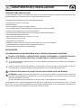 4
4
-
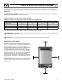 5
5
-
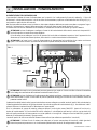 6
6
-
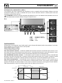 7
7
-
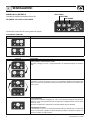 8
8
-
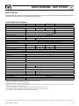 9
9
-
 10
10
-
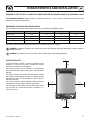 11
11
-
 12
12
-
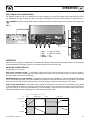 13
13
-
 14
14
-
 15
15
-
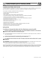 16
16
-
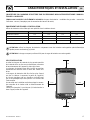 17
17
-
 18
18
-
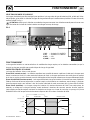 19
19
-
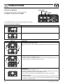 20
20
-
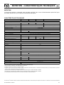 21
21
-
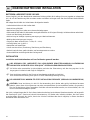 22
22
-
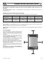 23
23
-
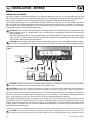 24
24
-
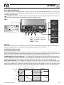 25
25
-
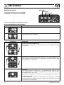 26
26
-
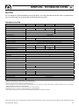 27
27
-
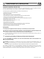 28
28
-
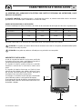 29
29
-
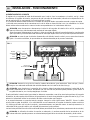 30
30
-
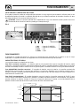 31
31
-
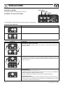 32
32
-
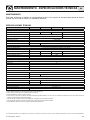 33
33
-
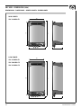 34
34
-
 35
35
-
 36
36


Quick SBC 365 NRG FR Manual Of Installation And Use
- Tipo
- Manual Of Installation And Use
- Este manual también es adecuado para
en otros idiomas
- français: Quick SBC 365 NRG FR
- italiano: Quick SBC 365 NRG FR
- English: Quick SBC 365 NRG FR
- Deutsch: Quick SBC 365 NRG FR
