Climbing Technology 2K651 Instrucciones de operación
- Tipo
- Instrucciones de operación

cover
Climbing Technology by Aludesign S.p.A. via Torchio 22
24034 Cisano B.sco BG ITALY www.climbingtechnology.com 1/24
Member of IST12-2D651CT_rev.9 04-22
ALPINE UP
EN Belay / rappel device
IT Assicuratore / discensore
FR Assureur / Descendeur
DE Sicherungs / Abseilgerät
ES Asegurador / Descensor
PT Segurador / Descensor
CZ Jistící / slaňovací zařízení
CN 保护/下降 设备
MADE IN ITALY
EN 15151-2:2012
PATENTED
G
=+S

drawings
Climbing Technology by Aludesign S.p.A. via Torchio 22
24034 Cisano B.sco BG ITALY www.climbingtechnology.com 2/24
Member of IST12-2D651CT_rev.9 04-22
Ø12 mm
TECHNICAL DATA
MODEL ALPINE UP KIT
REF. No. 2K651
WEIGHT 175 g (only device)
ROPE
FOR USE WITH ROPES EN892
½ half / twin ropes Ø 7.3 ÷ 9 mm
1 single rope Ø 8.6 ÷ 10.5 mm.
ATTENTION!
The term “rope” can
mean one or two strands of rope. When
using half or twin ropes, each strand of
rope must pass through its separate rope
slot. The term “Prusik” is used for indicate
any self-locking knot for climbing.
CONNECTOR YOU MUST USE:
the included hot forged light alloy
karabiner Concept SGL HC with hard
coat anodization. It presents a spring
bar which prevents the possibility of
the cross loading. You must use it,
connected to the belay loop of the
harness, during the use in CLICK UP
or DYNAMIC MODE. During the
belaying of 1-2 seconds, you must
use it on the anchor point (I).
TEST OF THIS
DEVICE MADE BY
VVUU a.s.
TESTING LABORATORY
Pikartska 1337/7 716 07
Ostrave - Radvanice
CZECH REPUBLIC
1 2 LEGEND
2.1 - leader 2.2 - hand 2.3 - second
2.4 - anchor 2.5 - fall 2.6 - lowering
76
F
D
C
2
1
E
B
A
8
G
H
3
4
5
I
9
B
17
16
15 14
10
GL
11
ROPE EN892
1
Ø 8.6÷10.5 mm
½
Ø
7.3÷9 mm
BB Y Y
PATENTED
MADE IN ITALY
13 12
EN 15151 -2
76
F
D
C
2
1
E
B
A
8
G
H
3
4
5
I
9
B
17
16
15 14
10
GL
11
ROPE EN892
1
Ø 8.6÷10.5 mm
½
Ø
7.3÷9 mm
BB Y Y
PATENTED
MADE IN ITALY
13 12
EN 15151 -2
NOMENCLATURE / MARKING
Each side presents a mode of use.
3.1 - SIDE A
3.2 - SIDE B
3
This mode is ideal for use on well-equipped multi-pitch sport climbing routes with fi xed anchors, such as bolts or glue-in an-
chors. A safety check between the climber and the belayer is essential before start climbing!
4.1
SETUP 4.2
SETUP 4.3
SETUP 4.4
SETUP IS OK! 4.5
LOCKING TEST 4.6
RELEASE
Connect the
karabiner to
the belay loop
of the harness.
Insert the loop of the rope in the slot
B, referring to symbols 2-6-8 on the
device. With single rope, use the
slot opposite the karabiner gate.
Insert the karabiner in the
hole F with the rope inside.
Close the karabiner gate!
The system is OK.
From now on always hold
the free end of the rope in
your hand!
Check the device works
correctly before use, verifying
that it locks the rope with a
typical “CLICK” sound.
To start belaying a leader,
push the device forwards
to return the karabiner to
position F.
4CLICK UP MODE
INSTALLATION AND SETUP

Climbing Technology by Aludesign S.p.A. via Torchio 22
24034 Cisano B.sco BG ITALY www.climbingtechnology.com 3/24
Member of IST12-2D651CT_rev.9 04-22
OK!
NO! NO!
Before start belaying it is mandatory to test the correct functioning of the device!
During belaying at all times hold the free end of the rope in your hand!
5.1
GIVING SLACK 5.2
TAKING UP SLACK 5.3
ARRESTING A FALL 5.4
LOWERING
5.5
WARNING! 5.6
OK! 5.7
WARNING!
With one hand, bend the free end
of the rope and feed it through
the device; with the other pull the
climber’s rope.
With one hand pull the free end of
the rope through the device; with
the other pull the climber’s rope
towards the device.
Hold the free end of the rope fi rmly
in one hand and pull it downwards.
Don’t hold the device in your
hands!
Open the lever H and push it
downwards, with the other hand
feed the free end of the rope
through the device.
During the belaying (5.1÷ 5.4)
always hold the free end of the
rope in your hand!
When ascending a multi-pitch
route, the rope must pass through
a directional anchorage on the
belay point.
Always pass the leader rope through
a directional anchorage, on the
belay station.
If not, danger of death!
5CLICK UP MODE
BELAYING THE LEADER

Climbing Technology by Aludesign S.p.A. via Torchio 22
24034 Cisano B.sco BG ITALY www.climbingtechnology.com 4/24
Member of IST12-2D651CT_rev.9 04-22
6.1
WARNING! 6.2
SAFE LOWERING 6.3
WARNING! 6.4
SAFE LOWERING
Alpine Up is positioned
correctly but the rope is in-
serted in a wrong way: stop
immediately the ascent!
Place the rope in the braking
groove A, accompany it
towards the device with both
hands and lower the climber.
Alpine Up is positioned in-
correctly and the rope is in-
serted in a wrong way: stop
immediately the ascent!
Place the rope in the braking
groove A, accompany it
towards the device with both
hands and lower the climber.
6CLICK UP MODE
SAFE, EVEN IN CASE OF ERROR
NO!
Even if the device is in the locked position, always hold the free end
of the rope in your hand!
7.1
SETUP 7.2
BELAYING 7.3
WARNING!
Before starting climbing,
take up slack (Fig. 5.2)
and activate the device in
lock mode.
With one hand pull and feed the
free end of the rope through the
device, with the other pull the
climber’s rope towards it.
During the belaying (7.1 - 7.2)
always hold the free end of the
rope in your hand!
7CLICK UP MODE
BELAYING IN TOP ROPE

Climbing Technology by Aludesign S.p.A. via Torchio 22
24034 Cisano B.sco BG ITALY www.climbingtechnology.com 5/24
Member of IST12-2D651CT_rev.9 04-22
1
2
To familiarize yourself with the device during your fi rst descents, it is recommended to use a Prusik knot under the Alpine Up (see 6). During the absei-
ling at all times hold the free end of the rope in your hand!
8.1
SETUP 8.2
TESTING / LOCKING 8.3
RETRIEVING THE ROPE 8.4
RELEASING THE SLING 8.5
ABSEILING
Belay yourself to the belay station
using a sling, connect the
karabiner to the belay loop and in-
sert the rope in the device.
Install the Alpine Up in the sling
and activate it in lock mode as
instructed under the point 5.2.
Take up the slack as instructed under
the point 6.2. and use your own
weight to tension the ropes and the
device.
Hold the free end of the rope in one
hand, with the other release the sling
karabiner and hook it to the gear
loop in the harness.
Open the lever H (1), press on it and
rotate the device upwards (2). Pull
the free end of the rope towards the
device, so to abseil.
8CLICK UP MODE
ABSEILING IN A SELF-LOCKING WAY
1
2
9.1
ABSEILING
To practice to abseiling in a
self-locking way, make a Prusik
knot on the rope below the
device.
9CLICK UP MODE / SELF LOCKING
ABSEILING - FIRST USES
additional
karabiner
1
2
This mode is ideal when the self-locking abseiling is quite dif-
fi cult.
10.1
SETUP 10.2
SETUP 10.3
ABSEILING
Install the device as instructed
under point 8.1-8.2, then in-
sert an additional locking kar-
abiner in the hole I.
Insert the rope in the addi-
tional carabiner, close the
gate, then follow the steps
under point 8.3-8.4.
Open the lever H (1), press on
it and rotate the device upwards
(2). Pull the free end of the rope
towards the device, so to abseil.
10 CLICK UP MODE / SELF LOCKING
ABSEILING - FACILITATED MODE

Climbing Technology by Aludesign S.p.A. via Torchio 22
24034 Cisano B.sco BG ITALY www.climbingtechnology.com 6/24
Member of IST12-2D651CT_rev.9 04-22
12
STOP!
OK!
NO! quickdraw
karabiner
This mode allows the belaying of one or two seconds simultaneously and independently.
After the setup and before the belaying you must test the system: pull on the rope on the climber’s side to verify that the self-locking function stops the rope on the climber’s side.
OK!
11.1
SETUP 11.2
SETUP 11.3
TESTING 11.4
BELAYING 1 SECOND 11.5
BELAYING 2 SECONDS 11.6
WARNING! 11.7
GRADUALLY RELEASING
NO!
Insert the rope in slots B ref. to
symbols 15-16 (1). Insert a wi-
de-base HMS karabiner in the
hole G with the rope inside (2).
Connect the Concept karabiner at
the center of the belay station and
connect it in the hole I, so that the
ropes remain below it.
Pull on the rope on the climber’s
side to verify that the self-locking
function stops the rope on the
climber’s side.
Use both hands to take up slack at
the climber end through the
device. Hold the free end of the
rope taut in both hands.
When using half or twin ropes,
always hold both free ends of
the ropes fi rmly in your hands
and taut!
Always hold both free ends of
the ropes fi rmly in your hands
and taut!
Insert a quickdraw karabiner in the
hole L, hold both free ends of the
rope fi rmly in your hand and push
your palm up.
11 BELAYING OF 1 OR 2 SECONDS
IN A SELF-LOCKING WAY

Climbing Technology by Aludesign S.p.A. via Torchio 22
24034 Cisano B.sco BG ITALY www.climbingtechnology.com 7/24
Member of IST12-2D651CT_rev.9 04-22
This mode is ideal for use on traditional climbing
routes with temporary anchors.
12.1
SETUP 12.2
SETUP 12.3
SETUP 12.4
SETUP IS OK!
Connect the
karabiner to the
belay loop of the
harness.
Insert the loop of the rope in
the slot B, referring to sym-
bols 2-7-8 on the device.
Insert the karabiner at right
angles to the lever H in the
hole G with the rope inside.
Close the karabiner gate!
The system is OK.
From now on always hold
fi rmly the free end of the
rope in your hand!
12 DYNAMIC MODE
INSTALLATION AND SETUP
NO!
Attention! A safety check between the climber and the belayer is essential before start climbing!
13.1
GIVING SLACK 13.2
TAKING UP SLACK 13.3
ARRESTING A FALL 13.4
LOWERING 13.5
WARNING!
With one hand, bend the free
end of the rope, with the other
pull and feed the climber’s
rope through the device.
With one hand pull and feed the
free end of the rope, with the other
pull the climber’s rope towards
the device.
Hold the free end of the rope
fi rmly in one hand and pull it
downwards. Don’t hold the
device in your hands!
Grasp the rope fi rmly with both
hands and move them alter-
nately downwards to lower the
climber to the ground.
During the belaying (13.1
÷13.4) hold fi rmly the free
end of the rope in your hand
at all times!
13 DYNAMIC MODE
BELAYING THE LEADER

Climbing Technology by Aludesign S.p.A. via Torchio 22
24034 Cisano B.sco BG ITALY www.climbingtechnology.com 8/24
Member of IST12-2D651CT_rev.9 04-22
In case of error stop the ascent
and lower the climber.
14.1
SAFE LOWERING 14.2
SAFE LOWERING
Place the rope in the braking
groove A, accompany it
towards the device and lower
the climber.
Place the rope in the braking
groove A, accompany it
towards the device and lower
the climber.
14 DYNAMIC MODE
SAFE, EVEN IN CASE OF ERROR
NO!
During belaying at all times hold the free end of the rope
in your hand!
15.1
SETUP 15.2
BELAYING 15.3
WARNING!
Before starting climbing,
setup the system as in
12.1÷ 12.4.
With one hand pull the free end
of the rope through the device;
with the other pull the climber’s
rope towards the device.
During the belaying
(15.1÷15.2) hold fi rmly the
free end of the rope in your
hand at all times!
15 DYNAMIC MODE
BELAYING THE SECOND IN TOP ROPE

Climbing Technology by Aludesign S.p.A. via Torchio 22
24034 Cisano B.sco BG ITALY www.climbingtechnology.com 9/24
Member of IST12-2D651CT_rev.9 04-22
With Alpine Up you can abseil in a classic way:
it works like a classic tuber descender and must be combined with a Prusik knot.
16.1
SETUP 16.2
TENSIONING 16.3
RELEASING THE SLING 16.4
ABSEILING
Belay yourself to the belay
station, install the device as in
12.1÷12.4 and tie a Prusik knot
on the rope below the device.
Tension the knot with
both hands so that
you can be suspen-
ded on the rope.
With one hand hold fi rmly the
free end of the rope, than rele-
ase the sling and disconnect the
karabiner from the belay station.
Control the Prusik knot with
one hand on the rope; with
the other hand control the
rate of descent.
16 DYNAMIC MODE
CLASSIC ABSEILING
H2O SOAP
MAX
30°C
WARNINGS
17

Climbing Technology by Aludesign S.p.A. via Torchio 22
24034 Cisano B.sco BG ITALY www.climbingtechnology.com 10/24
Member of IST12-2D651CT_rev.9 04-22
ENGLISH
The instruction manual for this device consists of general and specific instructions,
both must be carefully read and understood before use. Attention! This leaflet
shows the specific instruction only.
SPECIFIC INSTRUCTIONS ALPINE UP (PATENTED).
1) FIELD OF APPLICATION.
Alpine Up is a belay / rappel device for mountaineering and sport climbing
routes with one or more pitches that can be used with single, half or twin ropes.
It has two belaying modes, depending on the type of terrain: CLICK-UP MODE
(hand-assisted braking). For use on well-equipped sport climbing routes with fixed
anchors, such as bolts or glue-in anchors, and for sport climbing and indoor
climbing wall. Warning! Not suitable for use on traditional climbing routes and
adventure terrain; DYNAMIC MODE (manual braking). For adventure terrain and
traditional climbing routes with nuts, friends, pitons etc.
2) NAMES / MARKINGS.
The side A of the device has markings for belaying the leader in two modes, the
side B has markings for belaying 1 or 2 second climbers.
2.1 - Names of the parts. A) Braking groove (for use in case of error). B) Rope
loop insertion slots. C) Resistance lock cam. D) Braking area. E) Spring bar. F)
Hole for CLICK UP MODE karabiner. G) Hole for DYNAMIC MODE karabiner.
H) Ergonomic lever for abseiling / rappelling. I) Hole for belay station karabiner.
G) Hole for belaying karabiner. L) Hole for release karabiner.
2.2 - Markings. 1) Name of the manufacturer or of the responsible for the intro-
duction in the market. 2) Hand side. 3) EN 15151-2:2012 type 2: norm with
which Alpine Up is compliant. 4) UIAA logo. 5) Product name. 6) Hole for CLICK
UP MODE karabiner. 7) Hole for DYNAMIC MODE karabiner. 8) Climber side.
9) Hole for belay karabiner. 10) Compatible rope diameters and types. 11)
Karabiner hole for belaying second climbers. 12) Patented device. 13) Country of
fabrication. 14) Batch number (BBYY) composed of production batch number (BB)
and year of manufacture (YY). 15) Hand side. 16) Second climber side. 17) Logo
informing the user to read the attached user instruction carefully.
3) CHECK INSPECTION POINTS.
Prior to each use, it is necessary to check that all the tool components are in excel-
lent condition, without excessive wear and tear, cracks and/or burrs. Particularly
check the braking area (D) and the resistance lock cam (C), and ensure that the
spring bar (E) and the ergonomic lever (H) can fully depress and release smoothly,
without sticking. Check that the HMS karabiner is not worn out in its rope sliding
section.
4) COMPATIBILITY (Fig. 1).
Make sure the device is compatible with the other elements used.
4.1 - Ropes. Alpine Up is used with EN892 dynamic ropes: half and twin ropes
Ø 7.3÷9 mm; single ropes Ø 8.6÷10.5 mm. Braking efficiency and ease of
rope feed depend on the diameter and smoothness of the rope. Attention! The
use of wet or icy ropes can affect the efficiency of the device. Attention! In case
of use with two ropes, only use ropes having the same diameter and state of
consumption. Attention! The self locking abseil with a single rope is not allowed.
4.2 - Belay karabiner. A CONCEPT SGL hot-forged light-alloy karabiner with
hard anodized finish must be used. It has an anti-wear surface and a spring bar
to prevent cross-loading. This karabiner, connected to the belay loop on the har-
ness, must be inserted in holes F (CLICK-UP MODE) and G (DYNAMIC MODE).
When belaying 1 or 2 seconds, it must be connected to the belay station and
positioned in hole I.
4.3 - Karabiner for belaying seconds. When belaying 1 or 2 seconds, a wide-
base HMS karabiner must be used in the hole G. Warning! The karabiner must
be able to rotate around the base of the device (Fig. 11.2).
4.4 - Additional karabiners. For controlled release the rope of a second, insert a
quickdraw karabiner (Fig. 11.7) in hole L. For the self locking abseil - facilitated
mode, use preferably an HMS carabiner with a wide base, inserted in the hole
I (Fig. 9.1).
4.5 - Terminology. In this note, the term “rope” refers to one or two ropes. When
half or twin ropes are used, each one must pass through its own slot B in the
Alpine Up. The term “Prusik” is used for indicate any self-locking knot for climbing.
5) CLICK-UP MODE - INSTALLATION AND SETUP.
5.1 - Installation. Connect the karabiner to the belay loop on the harness, open
the bar and insert the belay loop (Fig. 4.1). Insert the loop of rope in the slots B
in the Alpine Up, referring to symbols 2-6-8 on the device (Fig. 4.2). Insert the
karabiner in the hole F with the rope inside (Fig. 4.3). The system is now ready for
use (Fig. 4.4). Warning! With a single rope, use slot B in the Alpine Up opposite
the karabiner gate.
5.2 - Function test (Fig. 4.5). Check the device works correctly each time before
use. When you have connected the Alpine Up to the harness, hold the free end of
the rope in one hand and pull the climber’s rope upwards with the other, checking
it locks the rope on the device with a typical “CLICK” sound.
5.3 - Releasing the device (Fig. 4.6). To start belaying the leader, or paying out
rope to the second after a stopping a fall, hold always the free end of the rope
in one hand and grip the Alpine Up in the other hand, as shown. Then push it
forwards to return the karabiner to position F.
6) CLICK-UP MODE - BELAYING THE LEAD CLIMBER.
Before setting out, the lead climber must be safely anchored and check that the
Alpine Up works correctly. Make sure the leader’s knot is correct and the rope is
uncoiled. Stand in a convenient position so as not to hinder operations. Warning!
Remember to hold the free end of the rope in your hand at all times! Risk of death!
When ascending a multi-pitch route, before setting up on a new pitch, the leader’s
rope rope must pass through a directional anchorage on the belay point. If not,
the Alpine Up may not work if the lead climber falls (figs. 5.6 and 5.7).
6.1 - Feeding the rope (Fig. 5.1). With one hand, bend the free end of the rope
and feed it through the Alpine Up. With the other pull and feed the climber’s rope
through the device, keeping the karabiner in position F. Always hold the free end
of the rope in one hand!
6.2 - Taking up slack (Fig. 5.2). With one hand pull and feed the free end of the
rope through the Alpine Up. With the other pull the climber’s rope towards the
device. Always hold the free end of the rope in one hand!
6.3 - Arresting a fall (Fig. 5.3). Hold the free end of the rope firmly in one hand
and pull it downwards. The device will lock the rope, with a typical “CLICK”
sound. Do not hold the Alpine Up in your hands. Always hold the free end of the
rope in one hand!
6.4 - Lowering the climber (Fig. 5.4). Activate the device in lock mode, as indi-
cated under point 6.2. Still holding the free end of the rope in one hand, open
the lever H and push it downwards, as shown. Lower the climber to the ground,
accompanying the free end of the rope towards the device. When the climber is
down, release the device as instructed under point 5.3. Warning! Do not pull the
lever down: the system would not allow lowering.
7) ALWAYS SAFE, EVEN IN THE EVENT OF AN ERROR.
The device will not work properly in the event of the installation errors (figs. 6.1-
6.3). If this happens, stop the ascent immediately and lower the climber as follows
(figs. 6.2-6.4). Place the rope in the braking groove A and accompany it towards
the device with both hands, alternating them downwards, lower the climber to
the ground.
8) BELAY ON TOP ROPE.
Warning! Remember to hold the free end of the rope in your hand at all times
(Fig. 7.3)!
8.1 - Installation (Fig. 7.1). Install and activate the device in lock mode, as
instructed under point 5.2. Check the climber’s rope-connecting knot is correct.
8.2 - Belaying (Fig. 7.2). With one hand pull and feed the free end of the rope
through the device, with the other pull the climber’s rope towards it, taking up
slack during ascent. If the climber falls or stops to rest, the system remains active
in rope-lock mode.
9) SELF-LOCKING ABSEIL.
Before descending, belay yourself to the belay station using a sling fixed securely
onto the harness. Prepare the descent rope and make sure it is properly unwound
and there is knot at the end.
9.1 - Installation (Fig. 8.1-8.2). Install the device in the sling at a minimum dis-
tance of 20 cm and activate it in lock mode, as instructed under point 5.2.
Warning! In this case the “climber side” symbol (8) identifies the end of the rope
in the anchor point direction (Fig. 8.1).
9.2 - Locking and tensioning (Fig. 8.3). Take up the slack as instructed under point
6.2 and use you own weight to tension the ropes and the system.
9.3 - Releasing the sling (Fig. 8.4). Holding the free end of the rope in one hand,
release the longe karabiner with the other.
9.4 - Abseiling (Fig. 8.5). Holding the free end of the rope in one hand, open
the lever H (1) with the other, pressing on it and rotating the device upwards (2),
as shown. Descend, pulling the free end of the rope towards the device. Atten-
tion! Do not pull the lever and device downwards as this would keep the system
braked.
10) SELF LOCKING ABSEILING - FIRST USES.
When using Alpine Up for the first time, it is advisable to use a Prusik knot on
the rope below the device to practice to abseiling (Fig. 9.1). Follow points 9.1
to 9.4. Proceed with the descent, keeping the knot unloaded. Warning! Install
Alpine Up at a distance that will prevent it from interfering with the Prusik knot.
11) SELF LOCKING ABSEILING - FACILITATED MODE.
There are some situations in which the abseiling can be quite difficult: high weight
of the ropes that are entirely hanging in a void; low weight of the climber (for ex.
children, young people, women); unfavourable ratio between the weight of the
climber and the weight of the ropes lying below the device. If any of the above
described cases occurs, it is necessary to relieve the load of the ropes from the
Alpine Up, in order to make smoother the descent. To perform this action, one of
the following methods must be applied: A - lift progressively the free end of the
ropes placed below the device, enough to allow a smooth descent; B - carry on
the following operations: install the Alpine Up as indicated under points 9.1-9.2
and insert an additional carabiner in the hole I (Fig. 10.1). Insert the ropes inside
the carabiner (Fig. 10.2), close the gate and follow the indications described
under points 9.3-9.4, Proceed with the descent as explained under point 9.4

Climbing Technology by Aludesign S.p.A. via Torchio 22
24034 Cisano B.sco BG ITALY www.climbingtechnology.com 11/24
Member of IST12-2D651CT_rev.9 04-22
(Fig. 10.3). Attention! It is possible to use this mode at any time during every
self-locking abseiling.
12) DYNAMIC MODE - INSTALLATION AND SET-UP.
12.1 - Installation. Connect the karabiner to the belay loop on the harness, open
the bar and insert the loop (Fig. 12.1). Insert the loop of rope in the slots B in the
Alpine Up, referring to symbols 2-7-8 on the device (Fig. 12.2). Insert the karabi-
ner at right angles to the lever H in the hole G with the rope inside (Fig. 12.3).
The system is now ready for use (Fig. 12.4).
13) DYNAMIC MODE - BELAYING THE LEAD CLIMBER.
Before setting out, the lead climber must be safely anchored and check that the
Alpine Up works correctly. Make sure the leader’s knot is correct and the rope is
uncoiled. Stand in a convenient position so as not to hinder operations. Warning!
Remember to hold the free end of the rope in your hand at all times! Risk of death!
When ascending a multi-pitch route, before setting up on a new pitch, the leader’s
rope must pass through a directional anchorage on the belay point. If not, it is not
possible to arrest a fall (figs. 5.6 and 5.7).
13.1 - Feeding the rope (Fig. 13.1). With one hand, bend the free end of the
rope and feed it through the Alpine Up. With the other pull and feed the climber’s
rope through the device. Always hold firmly the free end of the rope in one hand!
13.2 - Taking up slack (Fig. 13.2). With one hand pull and feed the free end of
the rope through the Alpine Up. With the other pull the climber’s rope towards the
device. Always hold firmly the free end of the rope in one hand!
13.3 - Arresting a fall (Fig. 13.3). Hold firmly the free end of the rope in one hand
and pull it downwards.
13.4 - Lowering the climber (Fig. 13.4). Grasp the rope firmly with both hands
and move them alternately downwards to lower the climber to the ground.
14) DYNAMIC MODE - ALWAYS SAFE, EVEN IN THE EVENT OF AN ERROR.
If either of the installation errors is committed (Fig. 14), follow the instructions under
point 7.
15) DYNAMIC MODE - BELAY ON TOP ROPE.
Warning! Remember to hold the free end of the rope in your hand at all times
(Fig. 15.3).
15.1 - Installation (Fig. 15.1). Install the system as instructed under point 12.
15.2 - Belaying (Fig. 15.2). With one hand pull and feed the free end of the rope
through the device, with the other accompany the climber’s rope towards it, taking
up slack during ascent.
16) DYNAMIC MODE - ABSEIL.
Before descending, belay yourself to the belay station using a longe fixed securely
onto the harness. Prepare the descent rope and make sure it is properly unwound
and there is knot at the end.
16.1 - Installation (Fig. 16.1). Install the karabiner in the sling at a minimum
distance of 20 cm from the harness. Insert the loop of rope in the slots B in the
Alpine Up, referring to symbols 2-7-8 on the device. Insert the karabiner at right
angles to the lever in the hole G with the rope inside. Tie a Prusik knot on the rope
below the device.
16.2 - Sling tensioning / release. Tension the Prusik knot (Fig. 16.2) so that you
can release the sling karabiner (Fig. 16.3).
16.3 - Abseiling (Fig. 16.4). Control the Prusik knot with one hand to prevent it
tightening round the rope. Control the rate of descent with the other hand, accom-
panying the free end of the rope towards the device.
17) BELAYING 1 OR 2 SECONDS.
17.1 - Installation. Insert the loop of the rope in slots B in the Alpine Up, referring
to symbols 15-16 on the device (Fig. 11.1). Insert a wide-base HMS belay kara-
biner in the hole G, at right angles to the lever, with the rope inside (Fig. 11.1).
Hook up the Concept SGL HMS karabiner in the hole I, than connect it at the top
of the belay point, so that the ropes are below it, held correctly inside the device
(Fig. 11.2). Warning! Make sure the climber’s rope is above the free end of the
rope and both the branches are below the karabiner in the hole I.
17.2 - Function test (Fig. 11.3). Pull the rope at the climber end to make sure the
self-locking system works.
17.3 - Belaying 1 or 2 seconds (Fig. 11.4-11.5) Use both hands to take up slack
at the climber end through the Alpine Up. Warning! Hold the free end of the rope
firmly in both hands and taut. Warning! When using half or twin ropes, always
hold both free ends of the ropes firmly in your hands and taut (Fig. 11.6).
17.4 - Releasing (Fig. 11.7). You can use the Alpine Up to gradually release
the rope of a second climber even under tension. Insert a quickdraw karabiner
in the hole L with the longest side at right angles to the device so that the belay
karabiner is below it. Hold both free ends of the rope firmly and taut in your hand
and push your palm up on the belay karabiner so that it comes into contact with
the other karabiner, creating leverage and allowing you to release the rope and/
or lower the climber.
18) LEGEND.
Leader (Fig. 2.1); Hand (Fig. 2.2); Second (Fig. 2.3); Anchor (Fig. 2.4); Fall (Fig.
2.5); Lowering (Fig. 2.6).

Climbing Technology by Aludesign S.p.A. via Torchio 22
24034 Cisano B.sco BG ITALY www.climbingtechnology.com 12/24
Member of IST12-2D651CT_rev.9 04-22
ITALIANO
Le istruzioni d’uso di questo dispositivo sono costituite da un’istruzione generale e
da una specifica ed entrambe devono essere lette attentamente prima dell’utiliz-
zo. Attenzione! Questo foglio costituisce solo l’istruzione specifica.
ISTRUZIONI SPECIFICHE ALPINE UP (BREVETTATO).
1) CAMPO DI APPLICAZIONE.
Alpine Up è un assicuratore / discensore per alpinismo e vie sportive a uno o
più tiri e può essere utilizzato con corda singola, mezze corde o corde gemelle.
Esso presenta due modalità di assicurazione, a seconda del terreno in cui ci si
trova: CLICK UP MODE (sistema di frenata manuale assistita). Per l‘arrampicata
su vie sportive ben attrezzate con ancoraggi fissi come spit o fittoni resinati, per
l’arrampicata in falesia e indoor. Attenzione! Modalità non adatta all’uso su
vie alpinistiche e terreno d‘avventura; DYNAMIC MODE (sistema di frenata ma-
nuale). Per l’arrampicata su terreno d’avventura e vie alpinistiche attrezzate con
friends, nuts, chiodi etc.
2) NOMENCLATURA / MARCATURA.
Il lato A del dispositivo riporta le indicazioni per l’assicurazione del primo nelle
due modalità; il lato B del dispositivo riporta quelle necessarie per l’assicurazione
di 1 o 2 secondi.
2.1 - Nomenclatura delle parti. A) Gola di frenaggio (da usarsi in caso di er-
rore). B) Sedi di inserimento asola di corda. C) Blocchi di contrasto. D) Zona di
frenaggio. E) Levetta mobile. F) Foro per moschettone CLICK UP MODE. G) Foro
per moschettone DYNAMIC MODE. H) Leva ergonomica per discesa in corda
doppia / calata. I) Foro per moschettone di sosta. G) Foro per moschettone di
assicurazione. L) Foro per moschettone di supporto allo sblocco.
2.2 - Indicazioni di marcatura. 1) Nome del produttore o del responsabile
dell’immissione sul mercato. 2) Indicazione lato mano. 3) EN 15151-2:2012
tipo 2: norma a cui il dispositivo è conforme. 4) Logo UIAA. 5) Nome del pro-
dotto. 6) Indicazione foro moschettone CLICK UP MODE. 7) Indicazione foro mo-
schettone DYNAMIC MODE. 8) Indicazioni lato arrampicatore. 9) Indicazione
foro per moschettone di sosta. 10) Diametri e tipologia corde compatibili. 11)
Indicazione foro moschettone per l’assicurazione dei secondi. 12) Dispositivo
brevettato. 13) Paese di fabbricazione. 14) Numero di lotto (BBYY) composto da
lotto di produzione (BB) e anno di fabbricazione (YY). 15) Indicazione lato mano.
16) Indicazione lato secondo di cordata. 17) Logo che avvisa l’utente di leggere
attentamente la nota informativa allegata.
3) CONTROLLO.
Prima di ogni utilizzo, verificare che tutti i componenti del dispositivo siano in
ottimo stato e non presentino eccessivi segni di usura, crepe, bave, etc. Verificare
in particolar modo la zona di frenaggio (D) e i blocchi di contrasto (C); verificare
che la levetta mobile (E) e la leva ergonomica (H) si muovano fino in fondo e
ritornino in posizione senza impuntamenti; controllare l‘usura del connettore HMS
nella zona di scorrimento.
4) COMPATIBILITÀ (Fig. 1).
Verificare la compatibilità del dispositivo con gli altri elementi presenti nel sistema.
4.1 - Corde. Alpine Up si utilizza con corde dinamiche EN 892: mezze corde o
corde gemelle Ø 7.3÷9 mm; corde singole Ø 8.6÷10.5 mm. L’efficacia frenante
e la facilità a dare corda dipendono dal diametro e dalla scivolosità della corda
stessa. Attenzione! L’utilizzo di corde bagnate o ghiacciate può compromettere
il corretto funzionamento dell’attrezzo. Attenzione! In caso di impiego con due
corde, utilizzare solo corde dello stesso diametro e stato di usura. Attenzione! La
discesa autobloccante su corda singola non è consentita.
4.2 - Moschettone di assicurazione. É obbligatorio utilizzare il moschettone
CONCEPT SGL in lega leggera forgiata a caldo e con anodizzazione dura. Esso
presenta una superficie anti-usura e una levetta mobile che previene il pericolo
di carico trasversale. Questo moschettone, collegato all’anello di servizio dell’im-
bracatura, deve essere posizionato nei fori F (CLICK UP MODE) e G (DYNAMIC
MODE). Durante l’assicurazione di 1-2 secondi, deve essere collegato alla sosta
e posizionato nel foro I.
4.3 - Moschettone per l’assicurazione dei secondi. Durante l’assicurazione di
1-2 secondi, nel foro G, si deve utilizzare un moschettone HMS a base larga.
Attenzione! Il moschettone deve poter ruotare attorno alla base dell’attrezzo (Fig.
11.2).
4.4 - Moschettoni addizionali. Per il rilascio controllato della corda del secondo
inserire nel foro L un moschettone da rinvio (Fig. 11.7). Per la discesa in corda
doppia autobloccante-modalità facilitata, utilizzare preferibilmente un moschetto-
ne HMS a base larga, inserito nel foro I (Fig. 9.1).
4.5 - Terminologia. Nella presente nota informativa, il termine “corda” verrà uti-
lizzato per indicare una o due corde. Quando si utilizzano mezze corde o corde
gemelle ognuna deve passare nella propria sede B dell’Alpine Up. Con il termine
“Prusik” si intende un qualsiasi nodo autobloccante per alpinismo.
5) CLICK UP MODE-INSTALLAZIONE E SETUP.
5.1 - Installazione. Agganciare il moschettone all‘anello di servizio dell‘imbra-
catura, aprire la levetta mobile e inserirvi l‘anello (Fig. 4.1). Inserire l’asola di
corda nelle sedi B dell’Alpine Up, facendo riferimento ai simboli 2-6-8 riportati
sul dispositivo (Fig. 4.2). Inserire il moschettone nel foro F con la corda al suo
interno (Fig. 4.3). Il sistema è così pronto per funzionare (Fig. 4.4). Attenzione!
In caso di utilizzo con corda singola, utilizzare la sede B dell’Alpine Up opposta
alla ghiera del moschettone!
5.2 - Test di funzionamento (Fig. 4.5). Prima di ogni utilizzo deve essere sempre
verificato il corretto funzionamento del dispositivo. Una volta installato e collegato
l’Alpine Up all‘imbracatura, trattenere il capo libero della corda con una mano e
con l‘altra tirare verso l‘alto la corda dell‘arrampicatore, verificando che questa si
arresti nel dispositivo emettendo il caratteristico suono “CLICK”.
5.3 - Sbloccaggio del dispositivo (Fig. 4.6). Per cominciare l’assicurazione del
primo o per ridare corda al compagno dopo l’arresto di un volo, tenere sempre
il lato libero della corda con una mano, con l‘altra mano impugnare l’Alpine Up
come mostrato e spingerlo successivamente in avanti, riportando così il moschet-
tone nella posizione F.
6) CLICK UP MODE-ASSICURAZIONE DEL PRIMO DI CORDATA.
Prima di assicurare l’assicuratore deve: auto-assicurarsi; verificare che l’Alpine Up
funzioni correttamente; verificare che il nodo di collegamento del primo di cor-
data sia corretto; verificare che la corda sia ben svolta; trovarsi in una posizione
comoda che non intralci le operazioni da svolgere. Attenzione! Durante tutte le
fasi dell’assicurazione è obbligatorio tenere sempre in mano il lato libero della
corda! Pericolo di morte! Durante la salita di una via a più tiri, prima di partire
per un nuovo tiro, è obbligatorio creare un punto di rinvio per la corda del primo
direttamente in sosta. In assenza di esso, l’Alpine Up, in caso di caduta del primo,
potrebbe non funzionare (Fig. 5.6-5.7)!
6.1 - Dare corda (Fig. 5.1). Con una mano curvare e accompagnare il lato libero
della corda nell’Alpine Up e con l’altra tirare e far scorrere la corda dell‘arrampi-
catore attraverso il dispositivo, mantenendo il moschettone in posizione F. Tenere
sempre il lato libero della corda con una mano!
6.2 - Recupero della corda lasca (Fig. 5.2). Con una mano tirare e far scorrere il
lato libero della corda attraverso l’Alpine Up, con l‘altra accompagnare la corda
dell‘arrampicatore verso il dispositivo. Tenere sempre il lato libero della corda
con una mano!
6.3 - Trattenere una caduta (Fig. 5.3). Tenere saldamente con una mano il lato
libero della corda portandolo verso il basso: il dispositivo bloccherà la corda
emettendo il classico suono “CLICK”. Non tenere in mano l’Alpine Up. Tenere
sempre il lato libero della corda con una mano!
6.4 - Calare l’arrampicatore (Fig. 5.4). Attivare il dispositivo in modalità di arre-
sto come al punto 5.2. Tenendo sempre il lato libero della corda con una mano,
aprire con l‘altra la leva H e spingere su di essa verso il basso come mostrato. Ac-
compagnando il lato libero della corda verso il dispositivo, calare il compagno a
terra. Al termine della calata sbloccare l’attrezzo come al punto 5.3. Attenzione!
Non tirare la leva verso il basso: il sistema non consentirebbe la calata!
7) SEMPRE SICURI, ANCHE IN CASO DI ERRORE.
Nel caso in cui si verifichi uno dei due errori di installazione mostrati (Fig. 6.1-
6.3) il dispositivo non funzionerà correttamente. In questo caso si dovrà interrom-
pere immediatamente la salita e calare l’arrampicatore nel seguente modo (Fig.
6.2-6.4): posizionare la corda nella cava di frenaggio A e con entrambe le mani
accompagnarla verso il dispositivo, spostandole una dopo l‘altra verso il basso in
modo da calare il compagno a terra.
8) ASSICURAZIONE CON CORDA DALL’ALTO.
Attenzione! Durante tutte le fasi dell’assicurazione è obbligatorio tenere sempre in
mano il lato libero della corda (Fig. 7.3).
8.1 - Installazione (Fig. 7.1). Installare e attivare il dispositivo in modalità di
bloccaggio come al punto 5.2. Verificare inoltre che il nodo di collegamento
dell’arrampicatore sia corretto.
8.2 - Assicurazione (Fig. 7.2). Con una mano tirare e far scorrere il lato libero
della corda attraverso il dispositivo, con l‘altra accompagnare la corda dell‘ar-
rampicatore verso di esso, recuperando così la corda durante la salita. In caso
di volo o riposo dell’arrampicatore, il sistema sarà sempre attivo in modalità di
bloccaggio corda.
9) DISCESA IN CORDA DOPPIA AUTOBLOCCANTE.
Prima della discesa è necessario: assicurarsi alla sosta con una longe fissata
all’imbracatura in modo sicuro; preparare la corda in sosta per la discesa e veri-
ficare che sia ben svolta ed abbia un nodo alla sua fine.
9.1 - Installazione (Fig. 8.1-8.2). Installare l’Alpine Up nella longe ad una di-
stanza minima di 20 cm e attivarlo in modalità di bloccaggio come al punto
5.2. Attenzione! Il simbolo “Indicazione lato arrampicatore” (8), in questo caso,
identifica il lato di corda in direzione del punto di ancoraggio (Fig. 8.1).
9.2 - Bloccaggio e tensionamento (Fig. 8.3). Recuperare la corda, come indicato
in 6.2, in modo da caricare con il proprio peso le corde e tensionare il sistema.
9.3 - Rilascio della longe (Fig. 8.4). Tenendo sempre con una mano il lato libero
della corda, sganciare con l’altra il moschettone della longe.
9.4 - Discesa in corda doppia (Fig. 8.5). Tenendo sempre il lato libero della
corda con una mano, aprire con l‘altra la leva H (1), spingere su di essa e ruotare
poi il dispositivo verso l’alto (2) come mostrato. Accompagnando il lato libero
della corda verso il dispositivo effettuare la discesa. Attenzione! Non tirare la
leva e il dispositivo verso il basso: il sistema rimarrebbe frenato.

Climbing Technology by Aludesign S.p.A. via Torchio 22
24034 Cisano B.sco BG ITALY www.climbingtechnology.com 13/24
Member of IST12-2D651CT_rev.9 04-22
10) PRIMI UTILIZZI IN CORDA DOPPIA AUTOBLOCCANTE.
Durante i primi utilizzi, al fine di prendere dimestichezza con la discesa in corda
doppia autobloccante, si consiglia di utilizzare un nodo Prusik sulla corda al di
sotto del dispositivo (Fig. 9.1). Seguire le operazioni da 9.1 a 9.4 e, mantenen-
do scarico il nodo Prusik, procedere con la discesa. Attenzione! Installare l’Alpine
Up ad una distanza tale che non interferisca con il nodo Prusik.
11) DISCESA IN CORDA DOPPIA AUTOBLOCCANTE-MODALITÀ FACILITATA.
Esistono alcune situazioni in cui la discesa in corda doppia può risultare piuttosto
difficoltosa: elevato peso delle corde interamente sospese nel vuoto; scarso peso
dell’arrampicatore (es. bambini, ragazzi, donne); rapporto sfavorevole fra il peso
dell’arrampicatore e quello delle corde al di sotto del dispositivo. In tutti questi
casi è necessario sgravare il peso delle corde dall’Alpine Up in modo da rendere
più fluida la discesa. Per fare questo è sufficiente applicare uno dei seguenti
metodi: A-sollevare progressivamente i lati liberi delle corde posti al di sotto del
dispositivo, quanto basta per consentire una discesa fluida; B-eseguire le seguenti
operazioni: installare l’Alpine Up come indicato ai punti 9.1-9.2 e inserire un
moschettone addizionale nel foro I (Fig. 10.1). Inserire le corde all’interno del
moschettone (Fig. 10.2), chiudere la ghiera e seguire le indicazioni espresse ai
punti 9.3-9.4. Procedere con la discesa come espresso al punto 9.4 (Fig. 10.3).
Attenzione! È possibile utilizzare questa modalità in ogni momento durante qual-
siasi discesa in corda doppia autobloccante.
12) DYNAMIC MODE-INSTALLAZIONE E SETUP.
12.1 - Installazione. Agganciare il moschettone all‘anello di servizio dell‘imbra-
catura, aprire la levetta mobile e inserirvi l‘anello (Fig. 12.1). Inserire l’asola di
corda nelle sedi B dell’Alpine Up, facendo riferimento ai simboli 2-7-8 riportati
sul dispositivo (Fig. 12.2). Inserire il moschettone perpendicolarmente alla leva
H nel foro G con la corda al suo interno (Fig. 12.3). Il sistema è così pronto per
funzionare (Fig. 12.4).
13) DYNAMIC MODE-ASSICURAZIONE DEL PRIMO DI CORDATA.
Prima di assicurare l’assicuratore deve: auto-assicurarsi; verificare che l’Alpine Up
funzioni correttamente; verificare che il nodo di collegamento del primo di cor-
data sia corretto; verificare che la corda sia ben svolta; trovarsi in una posizione
comoda che non intralci le operazioni da svolgere. Attenzione! Durante tutte le
fasi dell’assicurazione è obbligatorio tenere sempre saldamente in mano il lato
libero della corda! Pericolo di morte! Durante la salita di una via a più tiri, prima
di partire per un nuovo tiro, è obbligatorio creare un punto di rinvio per la corda
del primo direttamente in sosta. In assenza di esso, in caso di caduta del primo,
non è possibile arrestare la caduta (Fig. 5.6-5.7)!
13.1 - Dare corda (Fig. 13.1). Con una mano curvare e accompagnare il lato
libero della corda nell’Alpine Up e con l’altra tirare e far scorrere la corda dell‘ar-
rampicatore attraverso il dispositivo. Tenere sempre saldamente il lato libero della
corda con una mano!
13.2 - Recupero della corda lasca (Fig. 13.2). Con una mano tirare e far scorrere
il lato libero della corda attraverso l’Alpine Up, con l‘altra accompagnare la corda
dell‘arrampicatore verso il dispositivo. Tenere sempre saldamente il lato libero
della corda con una mano!
13.3 - Trattenere una caduta (Fig. 13.3). Con una mano tenere saldamente il
capo libero della corda portandola verso il basso.
13.4 - Calare l’arrampicatore (Fig. 13.4). Impugnare saldamente la corda con
entrambe le mani e spostarle una dopo l‘altra verso il basso in modo da calare
il compagno a terra.
14) DYNAMIC MODE-SEMPRE SICURI, ANCHE IN CASO DI ERRORE
Nel caso in cui si verifichi uno dei due errori di installazione mostrati (Fig. 14)
seguire le indicazioni espresse al punto 7.
15) DYNAMIC MODE-ASSICURAZIONE CON CORDA DALL’ALTO.
Attenzione! Durante tutte le fasi dell’assicurazione è obbligatorio tenere sempre
saldamente in mano il lato libero della corda (Fig. 15.3).
15.1 - Installazione (Fig. 15.1). Installare il sistema come al punto 12.
15.2 - Assicurazione (Fig. 15.2). Con una mano tirare e far scorrere il lato libero
della corda attraverso il dispositivo, con l‘altra accompagnare la corda dell‘ar-
rampicatore verso di esso, recuperando così la corda durante la salita.
16) DYNAMIC MODE-DISCESA IN CORDA DOPPIA.
Prima della discesa è necessario: assicurarsi alla sosta con una longe fissata
all’imbracatura in modo sicuro; preparare la corda in sosta per la discesa e veri-
ficare che sia ben svolta ed abbia un nodo alla sua fine.
16.1 - Installazione (Fig. 16.1). Installare il moschettone nella longe ad una
distanza minima di 20 cm dall’imbracatura. Inserire l’asola di corda nelle sedi B
dell’Alpine Up, facendo riferimento ai disegni 2-7-8 riportati sul dispositivo. Inse-
rire il moschettone perpendicolarmente alla leva nel foro G con la corda al suo
interno. Costruire un nodo Prusik sulla corda al di sotto del dispositivo.
16.2 - Tensionamento / rilascio longe. Mettere in tensione il nodo Prusik (Fig.
16.2) così da poter sganciare il moschettone della longe (Fig. 16.3).
16.3 - Discesa in corda doppia (Fig. 16.4). Gestire con una mano il nodo Prusik
in modo che non si stringa attorno alla corda e con l’altra controllare la velocità di
discesa accompagnando il lato libero della corda verso il dispositivo.
17) ASSICURAZIONE DI 1-2 SECONDI.
17.1 - Installazione. Inserire l’asola di corda nelle sedi B dell’Alpine Up, facendo
riferimento ai simboli 15-16 riportati sul dispositivo (Fig. 11.1). Inserire un mo-
schettone di assicurazione HMS a base larga nel foro G, perpendicolarmente
alla leva, con la corda al suo interno (Fig. 11.1). Agganciare il moschettone
HMS Concept SGL, collocato al vertice delle sosta, nel foro I, in modo che le
corde si trovino al di sotto di esso, correttamente contenute all’interno del dispo-
sitivo (Fig. 11.2). Attenzione! Verificare che la corda dell’arrampicatore si trovi
al di sopra del lato libero della corda e che tutti i rami si trovino al di sotto del
moschettone collocato nel foro I.
17.2 - Test di funzionamento (Fig. 11.3). Tirare la corda lato arrampicatore verso
il basso, per verificare che il sistema autobloccante funzioni.
17.3 - Assicurazione di 1 o 2 secondi (Fig. 11.4-11.5). Usare entrambe le mani
per recuperare regolarmente la corda lato arrampicatore attraverso il sistema.
Attenzione! Tenere sempre saldamente in mano e teso il lato libero della corda!
Attenzione! Durante l’uso con mezze corde o corde gemelle tenere sempre salda-
mente in mano e tesi entrambi i lati liberi delle corde (Fig. 11.6).
17.4 - Sbloccaggio (Fig. 11.7). Con Alpine Up è possibile sbloccare la corda di
un secondo in modo progressivo, anche sotto tensione. Inserire un moschettone
da rinvio nel foro L con l’asse maggiore perpendicolare al dispositivo e in modo
che il moschettone di assicurazione si trovi al di sotto di esso. Tenere saldamente
in mano e tesi entrambi i lati liberi delle corde e spingere con il palmo verso l’alto
sul moschettone di assicurazione: questo si appoggerà sull’altro moschettone cre-
ando una leva estremamente vantaggiosa che permetterà di rilasciare la corda
e/o calare il secondo.
18) LEGENDA.
Primo di cordata (Fig. 2.1); Mano (Fig. 2.2); Secondo (Fig. 2.3); Ancoraggio
(Fig. 2.4); Caduta (Fig. 2.5); Calata (Fig. 2.6).

Climbing Technology by Aludesign S.p.A. via Torchio 22
24034 Cisano B.sco BG ITALY www.climbingtechnology.com 14/24
Member of IST12-2D651CT_rev.9 04-22
FRANÇAIS
Les instructions d’utilisation de ce dispositif comprennent une partie générale et
une partie spécifique, lesquelles doivent toutes les deux être lues attentivement
avant utilisation. Attention ! La présente fiche ne contient que les instructions spé-
cifiques.
INSTRUCTIO
NS SPÉCIFIQUES ALPINE UP (BREVETÉ).
1) DOMAINE D’APPLICATION.
Alpine Up est un assureur/descendeur pour l’alpinisme et les voies sportives de
une ou plusieurs longueurs qui peut être utilisé en corde à simple, corde à double
ou cordes jumelées. Il présente deux modalités d’assurage selon le terrain où
vous vous trouvez : CLICK UP MODE (système de freinage manuel assisté). Pour
l’escalade en voies sportives bien équipées avec des ancrages fixes (spit ou piton
résiné), pour l’escalade en falaise et en salle. Attention ! Modalité non adaptée
aux itinéraires d’alpinisme et aux terrains d’aventure ; DYNAMIC MODE (système
de freinage manuel). Pour l’escalade en terrain d’aventure et en itinéraire d’alpi-
nisme équipé avec friends, coinceurs, pitons etc.
2) NOMENCLATURE / MARQUAGE.
Le côté A du dispositif montre les indications pour l’assurage du premier dans les
deux modalités ; le côté B affiche les indications pour l’assurage de un ou deux
seconds.
2.1 - Nomenclature des pièces. A) Gorge de freinage (à utiliser en cas d’erreur).
B) Sièges d’introduction de boucle de corde. C) Coinceurs. D) Zone de freinage.
E) Doigt de fermeture mobile. F) Trou pour mousqueton CLICK UP MODE. G) Trou
pour mousqueton DYNAMIC MODE. H) Doigt de fermeture ergonomique pour
descente en rappel. I) Trou pour mousqueton de halte. G) Trou pour mousqueton
d’assurage. L) Trou pour mousqueton de support au déblocage.
2.2 - Indications de marquage. 1) Nom du constructeur ou du responsable de
la mise sur le marché. 2) Indication côté main. 3) EN 15151-2:2012 type 2:
norme à laquelle le dispositif est conforme. 4) Logo UIAA. 5) Nom du produit.
6) Indication trou mousqueton CLICK UP MODE. 7) Indication trou mousqueton
DYNAMIC MODE. 8) Indications côté grimpeur. 9) Indication trou pour mous-
queton de relais. 10) Diamètres et type de cordes compatibles. 11) Indication
trou mousqueton pour l’assurage des seconds. 12) Produit breveté. 13) Pays de
fabrication. 14) Numéro de lot (BB-YY) composé du lot de production (BB) et
année de fabrication (YY). 15) Indication côté main. 16) Indication côté second
de cordée. 17) Logo avertissant l’utilisateur de la nécessité de lire attentivement la
notice d’information jointe.
3) VÉRIFICATION, POINTS À VÉRIFIER.
Avant toute utilisation, vérifiez le bon état de toutes les composantes du produit :
ils ne doivent pas être excessivement usés ni présenter des fissures, bavures, etc.
En particulier veuillez examiner la zone de freinage (D) et les coinceurs (C) et
veillez à ce que le doigt de fermeture (E) et le doigt de fermeture ergonomique (H)
accomplissent toute leur course et retournent en position sans se coincer. Vérifiez
l’usure du mousqueton HMS dans la zone de glissement.
4) COMPATIBILITÉ (Fig. 1).
Vérifier la compatibilité du dispositif avec les autres éléments présents dans le
système.
4.1 - Cordes. Alpine Up doit être utilisé avec des cordes dynamiques EN892 :
cordes à double et cordes jumelées Ø 7.3÷9 mm ; cordes à simple Ø 8.6÷10.5
mm. L’efficacité de freinage et la facilité pour donner du mou dépendent du
diamètre et de la qualité de la corde. Attention ! L’utilisation de cordes mouillées
ou gelées peut rendre difficile le fonctionnement correct du dispositif. Attention !
Dans le cas d’emploi avec deux cordes, il faut utiliser exclusivement des cordes
ayant le même diamètre et état d’usure. Attention ! La descente autobloquante sur
corde simple n’est pas permise.
4.2 - Mousqueton d’assurage. L’utilisation du mousqueton CONCEPT SGL, en
alliage léger forgé à chaud à anodisation dure, est obligatoire. Ce mousqueton
présente une surface anti-usure et un doigt de fermeture mobile qui prévient le
danger de charge transversale. Ce mousqueton, attaché à l’anneau pontet du
harnais, doit être placé dans les trous F (CLICK UP MODE) et G (DYNAMIC
MODE). Pendant l’assurage de 1-2 seconds, il doit être relié au mousqueton de
relais et placé dans le trou I.
4.3 - Mousqueton pour l’assurage des seconds. Pendant l’assurage de 1-2 se-
conds, utiliser dans le trou G, un mousqueton HMS à base large. Attention ! Le
mousqueton doit pouvoir tourner autour de la base de l’équipement (Fig. 11.2).
4.4 - Mousquetons additionnels. Pour le déblocage contrôlé d’un second, intro-
duisez dans le trou L un mousqueton de renvoi (Fig. 11.7). Pour la descente en
rappel autobloquant - modalité facilitée, utiliser de préférence un mousqueton
HMS à base large, introduit dans le trou I (Fig. 9.1).
4.5 - Lexique. Dans cette notice d’information, le terme “corde” désigne une ou
deux cordes. En cas d’utilisation de cordes à double ou de cordes jumelées, cha-
cune d’entre elles doit passer dans le logement B correspondant de l’Alpine Up. Le
terme “Prusik” est utilisé pour indiquer toute noeud autobloquant pour l’escalade.
5) CLICK UP MODE - INSTALLATION ET MISE AU POINT.
5.1 - Installation. Accrochez le mousqueton au pontet du harnais, ouvrez le doigt
de fermeture mobile et introduisez-le dans le pontet (Fig. 4.1). Introduisez la
boucle de corde dans les logements B de l’Alpine Up en prenant comme repères
les symboles 2-6-8 présents sur le dispositif (Fig. 4.2). Introduisez le mousqueton
dans le trou F avec la corde dedans (Fig. 4.3). Le système est maintenant prêt
pour fonctionner (Fig. 4.4). Attention ! En cas d’utilisation en corde à simple, se
servir du logement B de l’Alpine Up opposé à la bague du mousqueton !
5.2 - Essai de fonctionnement (Fig. 4.5). Avant chaque utilisation, vérifiez toujours
que l’équipement fonctionne correctement. Après avoir installé et relié l’Alpine Up
au harnais, retenez la corde côté libre d’une main et de l’autre, tirez vers le haut
la corde du grimpeur tout en vérifiant qu’elle se bloque dans le dispositif avec un
“CLICK“ caractéristique.
5.3 - Déblocage du dispositif (Fig. 4.6). Pour commencer l’assurage du premier
ou pour redonner du mou à votre compagnon après avoir bloqué un vol, tenez
toujours la corde côté libre d’une main et de l’autre, prenez l’Alpine Up comme
le montre la figure et poussez-le ensuite en avant de manière à reporter le mous-
queton dans la position F.
6) CLICK UP MODE - ASSURAGE DU PREMIER DE CORDÉE.
Avant d’assurer, l’assureur doit s’auto-assurer. Vérifiez que l’Alpine Up fonctionne
correctement : vérifiez que le nœud d’attache du premier de cordée est correct,
que la corde est bien déroulée. Placez-vous dans une position confortable qui
n’entrave pas l’exécution des opérations. Attention ! Pendant toutes les phases
d’assurage, tenez toujours obligatoirement en main la corde côté libre. Danger
de mort ! Pendant l’escalade d’un itinéraire de plusieurs longueurs, avant de partir
pour la longueur suivante, il est obligatoire de préparer un point de renvoi pour
la corde du premier directement sur le relais : si ce point est absent, l’Alpine Up
pourrait ne pas fonctionner en cas de chute du premier (Fig. 5.6-5.7) !
6.1 - Donner du mou (Fig. 5.1). D’une main, créez une boucle avec la corde
côté libre et accompagnez-la dans l’Alpine Up ; de l’autre, tirez sur la corde du
grimpeur et faites-la glisser à travers le dispositif tout en maintenant le mousqueton
dans la position F. Tenez toujours la corde côté libre avec une main !
6.2 - Récupérer du mou (Fig. 5.2). D’une main, tirez sur la corde côté libre et
faites-la glisser à travers l’Alpine Up, de l’autre accompagnez la corde du grim-
peur vers le dispositif. Tenez toujours la corde côté libre avec une main !
6.3 - Retenir une chute (Fig. 5.3). D’une main, tenez fermement la corde côté
libre tout en la portant vers le bas. Le dispositif bloque la corde : vous entendrez le
son classique d’un déclic. Ne tenez pas l’Alpine Up dans la main. Tenez toujours
la corde côté libre avec une main !
6.4 - Faire descendre le grimpeur (Fig. 5.4). Activez le dispositif en mode d’arrêt
comme indiqué au point 5.2. En tenant toujours la corde côté libre d’une main,
ouvrez avec l’autre le doigt de fermeture H et appuyez dessus vers le bas comme
le montre la figure. En accompagnant la corde côté libre vers le dispositif, faites
descendre votre compagnon au sol. À la fin de la descente, débloquez l’équipe-
ment comme il est indiqué au point 5.3. Attention ! Ne tirez pas sur le doigt de
fermeture vers le bas : le système ne permettrait pas la descente !
7) TOUJOURS SÛR, MÊME EN CAS D’ERREUR.
En présence d’une des deux erreurs d’installation indiquées (Fig. 6.1-6.3), le
dispositif ne fonctionne pas correctement. Dans ce cas, vous devez interrompre le
plus rapidement l’escalade et faire descendre le grimpeur de la manière suivante
(Fig. 6.2-6.4) : positionnez la corde dans la gorge de freinage A et accompa-
gnez-la avec les deux mains vers le dispositif ; déplacez les mains l’une après
l’autre vers le bas pour faire descendre votre compagnon au sol.
8) ASSURAGE D’UNE MOULINETTE.
Attention ! Pendant toutes les phases d’assurage, tenez toujours obligatoirement
en la main la corde côté libre (Fig. 7.3).
8.1 - Installation (Fig. 7.1). Installez et activez le dispositif en mode de blocage
comme il est indiqué au point 5.2. Vérifiez que le nœud d’attache du grimpeur
est correct.
8.2 - Assurage (Fig. 7.2). D’une main, tirez sur la corde côté libre et faites-la
glisser à travers le dispositif, de l’autre accompagnez la corde du grimpeur vers
le dispositif de façon à récupérer la corde pendant l’escalade En cas de vol ou
de repos du grimpeur, le système sera toujours actif en mode de blocage de la
corde.
9) DESCENTE EN RAPPEL AUTOBLOQUANT.
Avant la descente, vous devez nécessairement vous assurer au relais avec une
longe fixée solidement au harnais. Du relais, préparez la corde pour la descente,
vérifiez qu’elle est bien déroulée et qu’elle a un nœud à la fin.
9.1 - Installation (Fig. 8.1-8.2). Installez l’Alpine Up dans une longe à une dis-
tance d’au moins 20 cm et activez-le en mode de blocage comme indiqué au
point 5.2. Attention ! Le symbole “Indication côté grimpeur” (8) identifie dans
ce cas le côté de corde qui est dans la direction du point d’ancrage (Fig. 8.1).
9.2 - Blocage et tensionnement (Fig. 8.3). Récupérez la corde comme il est indi-
qué au paragraphe 6.2 de façon à charger les cordes de votre poids et à mettre
en tension le système.
9.3 - Relâchement de la longe (Fig. 8.4). Tout en tenant toujours d’une main la
corde côté libre enlever votre longe qui était fixée au relais.
9.4 - Descente en rappel (Fig. 8.5). En tenant toujours la corde côté libre d’une

Climbing Technology by Aludesign S.p.A. via Torchio 22
24034 Cisano B.sco BG ITALY www.climbingtechnology.com 15/24
Member of IST12-2D651CT_rev.9 04-22
main, ouvrez avec l’autre le doigt de fermeture H (1), appuyez dessus et tournez
le dispositif vers le haut (2) comme le montre la figure. En accompagnant la corde
côté libre vers le dispositif, effectuez la descente. Attention ! Ne tirez pas sur
le doigt de fermeture et le dispositif vers le bas : le système resterait en position
freinée.
10) PREMIÈRE UTILISATION DU RAPPEL AUTOBLOQUANT.
Afin de vous familiariser avec la descente en rappel autobloquant lors des pre-
mières utilisations, nous vous conseillons d’utiliser un nœud Prusik sur la corde
(Fig. 9.1). Effectuer les opérations 9.1 à 9.4 et procéder à la descente tout en
maintenant le nœud autobloquant déchargé. Attention ! Installez Alpine Up à une
distance qui n’interfère pas avec le nœud autobloquant.
11) DESCENTE EN RAPPEL AUTOBLOQUANT - MODALITÉ FACILITÉE.
Il y a des situations dans lesquelles la descente en rappel peut résulter plutôt
difficile : poids élevé des cordes qui sont totalement suspendues dans le vide ;
poids léger du grimpeur (par ex. enfants, jeunes hommes / femmes, femmes) ;
rapport défavorable entre le poids du grimpeur et le poids des cordes au dessous
du dispositif. Dans tous ces cas, il faut enlever le poids par les cordes de l’Alpine
Up, afin que la descente soit plus fluide. Pour faire ça, il est suffisant de suivre une
des modalités suivantes : A - soulever progressivement les côtés libres des cordes
qui sont positionnés au dessous du dispositif, de manière suffisante à permettre
une descente fluide ;
B - exécuter les opérations suivantes : installer l’Alpine Up comme indiqué aux
points 9.1-9.2 et introduire un mousqueton additionnel dans le trou I (Fig. 10.1).
Introduire les corde à l’intérieur du mousqueton (Fig. 10.2), fermer la bague et
suivre les indications fournies aux points 9.3-9.4. Procéder à la descente comme
indiqué au point 9.4 (Fig. 10.3). Attention ! Il est possible de utiliser cette moda-
lité en tout moment pendant chaque descente en rappel autobloquant.
12) DYNAMIC MODE - INSTALLATION ET MISE AU POINT.
12.1 - Installation. Accrocher le mousqueton au pontet du harnais, ouvrir le doigt
de fermeture mobile et y introduire l’anneau (Fig. 12.1). Introduire la boucle de
corde dans les logements B de l’Alpine Up en prenant comme repères les sym-
boles 2-7-8 présents sur le dispositif (Fig. 12.2). Introduire le mousqueton dans le
trou G avec la corde dedans perpendiculairement au doigt de fermeture H (Fig.
12.3). Le système est maintenant prêt pour fonctionner (Fig. 12.4).
13) DYNAMIC MODE - ASSURAGE DU PREMIER DE CORDÉE.
Avant d’assurer, l’assureur doit s’auto-assurer. Vérifiez que l’Alpine Up fonctionne
correctement : vérifiez que le nœud d’attache du premier de cordée est correct,
que la corde est bien déroulée. Placez-vous dans une position confortable qui
n’entrave pas l’exécution des opérations. Attention ! Pendant toutes les phases
d’assurage, tenez toujours obligatoirement en main la corde côté libre. Danger
de mort ! Pendant l’escalade d’un itinéraire de plusieurs longueurs, avant de partir
pour la longueur suivante, il est obligatoire de préparer un point de renvoi pour la
corde du premier directement sur le relais : si ce point est absent, en cas de chute
du premier, il n’est pas possible d’arreter la chute (Fig. 5.6-5.7) !
13.1 - Donner du mou (Fig. 13.1). D’une main, créez une boucle avec la corde
côté libre et accompagnez-la dans l’Alpine Up ; de l’autre, tirez sur la corde du
grimpeur et faites-la glisser à travers le dispositif. Tenez toujours fermement la
corde côté libre dans la main !
13.2 - Récupérer du mou (Fig. 13.2). D’une main, tirez sur la corde côté libre et
faites-la glisser à travers l’Alpine Up, de l’autre accompagnez la corde du grim-
peur vers le dispositif. Tenez toujours fermement la corde côté libre dans la main !
13.3 - Retenir une chute (Fig. 13.3). D’une main, tenez fermement la corde côté
libre tout en la portant vers le bas.
13.4 - Faire descendre le grimpeur (Fig. 13.4). Saisissez fermement la corde
des deux mains ; déplacez les mains l’une après l’autre vers le bas pour faire
descendre votre compagnon au sol.
14) DYNAMIC MODE - TOUJOURS SÛR, MÊME EN CAS D’ERREUR.
En présence d’une des deux erreurs d’installation indiquées (Fig. 14), suivre les
indications fournies au point 7.
15) DYNAMIC MODE - ASSURAGE D’UNE MOULINETTE.
Attention ! Pendant toutes les phases d’assurage, vous devez obligatoirement
toujours tenir fermement dans la main la corde côté libre (Fig. 15.3).
15.1 - Installation (Fig. 15.1). Installez le système conformément aux indications
du paragraphe 12.
15.2 - Assurage (Fig. 15.2). D’une main, tirez sur la corde côté libre et faites-la
glisser à travers le dispositif, de l’autre accompagnez la corde du grimpeur vers le
dispositif de façon à récupérer la corde pendant l’escalade.
16) DYNAMIC MODE - DESCENTE EN RAPPEL.
Avant la descente, vous devez nécessairement vous assurer au relais avec une
longe fixée solidement au harnais. Du relais, préparez la corde pour la descente,
vérifiez qu’elle est bien déroulée et qu’elle a un nœud à la fin.
16.1 - Installation (Fig. 16.1). Installez le mousqueton dans une longe à une
distance d’au moins 20 cm du harnais. Introduire la boucle de corde dans les
logements B de l’Alpine Up en prenant comme repères les dessins 2-7-8 présents
sur le dispositif. Introduire le mousqueton dans le trou G, avec la corde dedans,
perpendiculairement au doigt de fermeture. Formez un nœud Prusik sur la corde
au-dessous du dispositif.
16.2 - Tensionnement / relâchement de la longe. Mettre sous tension le nœud
Prusik (Fig. 16.2) de façon à pouvoir décrocher le mousqueton de la longe de
relais (Fig. 16.3).
16.3 - Descente en rappel (Fig. 16.4). Contrôlez d’une main le nœud Prusik de
façon à ce qu’il ne se serre pas autour de la corde ; de l’autre, contrôlez la vitesse
de descente en accompagnant la corde côté libre vers les dispositifs.
17) ASSURAGE DE 1-2 SECONDS.
17.1 - Installation. Introduire la boucle de corde dans les logements B de l’Alpine
Up en prenant comme repères les symboles 15-16 présents sur le dispositif (Fig.
11.1). Introduire un mousqueton d’assurage HMS à base large dans le trou G,
avec la corde dedans, perpendiculairement au doigt de fermeture (Fig. 11.1).
Accrochez le mousqueton HMS Concept SGL, placé au sommet du dispositif de
halte, dans le trou I de façon à ce que les cordes se trouvent au-dessous de ce
dernier, contenues à l’intérieur du dispositif (Fig. 11.2). Attention ! Vérifiez que
la corde du grimpeur se trouve au-dessus de la corde côté libre et que toutes les
branches se trouvent au-dessous du mousqueton qui est placé dans le trou I.
17.2 - Essai de fonctionnement (Fig. 11.3). Tirez sur la corde côté grimpeur vers
le bas de façon à vérifier si le système autobloquant fonctionne.
17.3 - Assurage de 1 ou 2 seconds (Fig. 11.4-11.5). Servez-vous des deux
mains pour rattraper orde côté grimpeur à travers le système. Attention ! Tenez
toujours la corde côté libre fermement dans la main et bien tendue. Attention !
Lors de l’utilisation avec des cordes à double ou des cordes jumelées, tenez les
deux côtés libres des cordes fermement dans la main et bien tendus (Fig. 11.6).
17.4 - Déblocage (Fig. 11.7). Avec Alpine Up, il est possible de débloquer la
corde d’un second progressivement, même sous tension. Introduisez le mousque-
ton de renvoi dans le trou L, l’axe majeur perpendiculaire au dispositif et de telle
sorte que le mousqueton d’assurage se trouve au-dessous de celui-ci. Tenez les
deux côtés libres des cordes fermement et bien tendus dans la main et poussez
le mousqueton d’assurage avec la paume vers le haut : il s’appuiera sur l’autre
mousqueton de façon à créer un levier extrêmement avantageux qui permettra de
relâcher la corde et/ou de faire descendre le second.
18) LÉGENDE.
Premier (Fig. 2.1) ; Main (Fig. 2.2) ; Second (Fig. 2.3) ; Amarrage (Fig. 2.4) ;
Chute (Fig. 2.5) ; Descente (Fig. 2.6).

Climbing Technology by Aludesign S.p.A. via Torchio 22
24034 Cisano B.sco BG ITALY www.climbingtechnology.com 16/24
Member of IST12-2D651CT_rev.9 04-22
DEUTSCH
Die Gebrauchsanweisung zu diesem Produkt setzt sich aus einem allgemeinen
und einem spezifischen Teil zusammen, wobei beide Teile vor der Verwendung
des Produkts genau durchgelesen werden müssen. Achtung! Dieses Blatt enthält
nur den allgemeinen Teil der Anleitung.
SPEZIFISCHE ANWEISUNGEN ALPINE UP (PATENTIERT).
1) ANWENDUNGSBEREICH.
Alpine Up ist ein Absicherungs-/Abseilgerät für das Bergsteigen und Sportklettern
von einer oder mehreren Seillängen und kann sowohl mit Einfachseilen, Halb-
seilen als auch Zwillingsseilen verwendet werden. Das Gerät hat zwei Absiche-
rungsmodi, je nach dem Gelände, in dem es verwendet wird: CLICK UP MODE
(manuelles unterstütztes Bremssystem). Für das Klettern in Routen mit gut befestigten
Verankerungen, wie Bohrhaken oder Harz-Ösendübel, sowie für das Sport- und
Indoor- Klettern. Achtung! Dieser Modus darf auf Alpinrouten und Abenteuerge-
länden nicht benutzt werden; DYNAMIC MODE (Manuelles Bremssystem). Für das
Klettern auf Abendteuergelände und Alpinrouten, die mit Nägeln, Friends, Nuts
usw. ausgerüstet sind.
2) BENENNUNG / MARKIERUNG.
Auf der Seite A des Geräts befinden sich die Angaben für die Sicherung des Vor-
steigenden im zwei Modi, auf der Seite B stehen die Angaben für die Sicherung
von 1 oder 2 Nachsteigenden.
2.1 - Benennung der Teile. A) Bremsrille (nur im Fehlerfall benutzen). B) Einlage-
stellen der Seilöse. C) Kontrastblockierung. D) Bremszone. E) Mobiler Hebel. F)
Bohrung für Karabiner CLICK UP MODE. G) Bohrung für Karabiner DYNAMIC
MODE. H) Ergonomischer Hebel für das Abseilen mit Doppelseil / Abseilen. I)
Bohrung für den Rastkarabiner. G) Bohrung für den Sicherungskarabiner. L) Boh-
rung für den Freigabe-Unterstützungskarabiner.
2.2 - Markierungsangaben. 1) Name des Herstellers oder des verantwortlichen
Vermarkters. 2) Angabe der Handseite. 3) N 15151-2:2012 Typ 2: das Gerät
entspricht dieser Norm. 4) UIAA Logo. 5) Produktsname. 6) Angabe Karabiner-
bohrung CLICK UP MODE. 7) Angabe Karabinerbohrung DYNAMIC MODE. 8)
Angabe der Seite des Kletterers. 9) Angabe der Bohrung für den Rastkarabiner.
10) Durchmesser und Typologie der zu verwendenden Seile. 11) Angabe der
Bohrung für den Absicherungskarabiner für die Nachsteigenden.12) Patientier-
tes Gerät. 13) Herstellungslandes. 14) Lotnummer (BBYY), bestehend aus Herstel-
lungs-Lot (BB) Herstellungsjahr (YY). 15) Angabe der Handseite. 16) Angabe der
Seite des Nachsteigenden. 17) Logo, das den Benutzer darauf hinweist, das
beiliegende Informationsblatt aufmerksam durchzulesen.
3) Kontrolle, die zu überprüfende Stellen.
Vor jedem Gebrauch muss das Gerät überprüft werden. Alle Bauteile müssen auf
eventuelle verschlesserscheinungen überprüft werden. Es muss insbesondere die
Bremszone (D) und die Kontrastblockierung (C) überprüft werden um sicherzustel-
len, dass sich der mobil Hebel (E) und der ergonomisch Hebel (H) bis zu ihrem
Ende bewegen und, ohne zu stocken in Position zurückspringen; die Anschlussvor-
richtung HMS in der Gleitzone auf Verschleiß überprüfen.
4) KOMPATIBILITÄT (Abb. 1).
Es muss die Kompatibilität der Vorrichtung mit den anderen im System vorhande-
nen Bauteilen überprüft werden.
4.1 - Seile. Das Alpine Up-Gerät wird mit dynamischen Seilen EN892 benutzt:
Halbseile und Zwillingsseile Ø 7.3÷9 mm; Einfachseile Ø 8.6÷10.5 mm. Die
Bremsleistung und die Leichtigkeit bei der Seilausgabe hängen vom Durchmesser
und der Gleitfähigkeit des Seiles selbst ab. Achtung! Nasse oder gefrorene Seile
können die korrekte Arbeitsweise des Gerätes beeinträchtigen. Achtung! Im Falle
der Benutzung mit zwei Seilen nur Seile mit gleichem Durchmesser und Zustand
verwenden. Achtung! Selbstblockierendes Abseilen mit einem einzigen Seil ist
nicht erlaubt.
4.2 - Sicherungskarabiner. Es müssen Karabiner CONCEPT SGL aus warmge-
schmiedeter Leichtmetall-Legierung mit hartem Eloxal-Verfahren verwendet werden.
Dieser hat eine verschleißbeständige Oberfläche und einen mobilen Hebel, der
der Gefahr einer Querbelastung vorbeugt. Dieser Karabiner, der an dem Verbin-
dungsring des Absturzsicherheitsgurts angeschlossen ist, muss in den Bohrungen
F (CLICK UP MODE) und G (DYNAMIC MODE) positioniert werden. Während
der Nachstiegssicherung muss dieser an die Raststelle angeschlossen und in die
Bohrung I positioniert werden.
4.3 - Absicherungskarabiner für die Nachstiegssicherung. Bei der Nachstiegs-
sicherung, muss in der Bohrung G ein HMS-Karabiner mit breitem Fuß verwendet
werden. Achtung! Der Karabiner muss sich um die untere Seite des Gerätes dre-
hen können (Abb. 11.2).
4.4 - Zusätzliche Karabiner
Für ein gesteuertes Ablassen des Nachsteigenden muss in der Bohrung L ein Vor-
gelege-Karabiner positioniert werden (Abb. 11.7). Für Selbstblockierendes Absei-
len - erleichterten Modus verwenden, vorzugsweise einen breiten HMS Karabiner,
eingehängt in die Bohrung I (Abb. 9.1).
4.5 - Terminologie. In diesem Informationsblatt wird der Begriff “Seil“ zur Be-
zeichnung eines oder zweier Seile benutzt. Wenn Halbseile bzw. Zwillingsseile
verwendet werden, muss jedes Seil durch den entsprechenden Sitz B des Alpine
Up-Gerätes gezogen werden. Der Begriff “Prusikschlinge“ wird zur Bezeichnung
jedes selbstblockierenden Knotens für das Bergsteigenbenutzt.
5) CLICK UP MODE - MONTAGE UND SETUP.
5.1 - Montage. Den Karabiner am Sicherheitsgurtring befestigen, den mobilen
Hebel öffnen und den Ring einhaken (Abb. 4.1). Die Seilöse in die entsprechende
Vorrichtung B des Alpine Up-Gerätes einziehen, unter Beachtung der auf dem
Gerät angegebenen Symbole 2-6-8 (Abb. 4.2). Den Karabiner in die Bohrung
F mit dem innen liegenden Seil positionieren (Abb. 4.3). Jetzt ist das System
funktionsbereit (Abb. 4.4). Achtung! Wird das Gerät mit einem Einfachseil einge-
setzt, muss die dem Karabinerring gegenüberliegende Vorrichtung B des Alpine
Up-Gerätes benutzt werden!
5.2 - Funktionstest (Abb. 4.5). Vor jedem Gebrauch muss die Funktionstüchtig-
keit des Gerätes sichergestellt werden. Nach Montage und Anschluss des Alpine
Up-Gerätes an den Sicherheitsgurt, das freie Seilende mit einer Hand halten und
mit der anderen das Seil des Kletterers nach oben ziehen und sicherstellen, dass
dieses mit dem charakteristischen “KLICK“-Geräusch in die Vorrichtung einrastet.
5.3 - Vorrichtungsfreigabe (Abb. 4.6). Für den Vorstiegssicherungsvorgang oder
für die Seilausgabe an den Partner nach dem Aufhalten eines Sturzes muss immer
mit einer Hand das freie Seilende gehalten und mit der anderen das Alpine
Up-Gerät entsprechend der Abbildung gehalten und dann nach vorne gedrückt
werden, um den Karabiner wieder in die Position F zurückzubringen.
6) CLICK UP MODE - VORSTIEGSSICHERUNG.
Bevor der abzusichernde Partner abgesichert wird, muss er sich selbst absichern,
sicherstellen, dass das Gerät korrekt funktioniert, überprüfen, dass sein Verbin-
dungsknoten korrekt ist, überprüfen, dass das Seil gut abgewickelt ist und sich in
einer bequeme Position befinden, damit die durchzuführenden Arbeiten nicht be-
hindert werden. Achtung! Bei allen Absicherungsphasen muss das freie Seilende
immer mit einer Hand gehalten werden! Todesgefahr! Während des Aufstiegs in
Routen mit mehreren Seillängen muss, bevor man mit einer neuen Seillänge be-
ginnt, eine Richtungsverankerung für die Seile des Vorsteigenden direkt am Stand-
platz eingerichtet werden. Wenn eine Richtungsverankerung fehlt, könnte das Alpi-
ne Up-Gerät, im Falle eines Sturzes des Vorsteigenden versagen (Abb. 5.6 - 5.7)!
6.1 - Seil ausgeben (Abb. 5.1). Mit einer Hand das freie Seilende biegen und in
das Alpine Up-Gerät schieben und mit der anderen das Seil des Kletterers ziehen
und durch die Vorrichtung gleiten lassen. Der Karabiner muss in Position F bleiben.
Das freie Seilende muss immer mit einer Hand gehalten werden!
6.2 - Einziehen des lockeren Seils (Abb. 5.2). Mit einer Hand das freie Seilende
ziehen und durch das Alpine Up-Gerät gleiten lassen und mit der anderen das Seil
des Kletterers zur Vorrichtung schieben. Das freie Seilende muss immer mit einer
Hand gehalten werden!
6.3 - Einen Sturz auffangen (Abb. 5.3). Das freie Seilende mit einer Hand gut
festhalten und es nach unten ziehen. Die Vorrichtung wird das Seil mit dem charak-
teristischen “KLICK”-Geräusch blockieren. Das Alpine Up-Gerät darf nicht festge-
halten werden. Das freie Seilende muss immer mit einer Hand gehalten werden!
6.4 - Den Kletterer ablassen (Abb. 5.4). Das Gerät in den Blockierungsmodus
gemäß Punkt 5.2 bringen. Mit einer Hand das freie Seilende halten, mit der
anderen den Hebel H öffnen und ihn nach unten drücken, wie dargestellt. Den
Partner bis zum Boden absenken, indem das freie Seilende zum Gerät geschoben
wird. Nach dem Ablassen muss das Gerät gemäß Punkt 5.3 wieder freigegeben
werden. Achtung! Der Hebel darf nicht nach unten gezogen werden: Das System
würde die Senkung nicht zulassen!
7) IMMER SICHER, AUCH IM FEHLERFALL.
Sollte sich einer der beiden dargestellten Montagefehler (Abb. 6.1-6.3) ergeben,
funktioniert das Gerät nicht korrekt. In diesem Fall muss der Aufstieg unverzüglich
unterbrochen und der Kletterer folgendermaßen abgelassen werden (Abb. 6.2-
6.4): das Seil in die Bremsaussparung A positionieren und es mit beiden Händen
zum Gerät schieben, indem sie, eine nach der anderen, abwärts verschoben
werden, um den Kameraden abzulassen.
8) TOPROPE-SICHERUNG.
Achtung! Bei den Sicherungsphasen muss das freie Seilende unbedingt mit einer
Hand gehalten werden (Abb. 7.3).
8.1 - Montage (Abb. 7.1). Das Gerät in den Blockierungsmodus wie in Punkt
5.2 bringen und betätigen. Es muss außerdem sichergestellt werden, dass der
Verbindungsknoten des Kletterers korrekt ist.
8.2 - Sicherung (Abb. 7.2). Mit einer Hand das freie Seilende ziehen und durch
das Gerät gleiten lassen, mit der anderen das Seil des Kletterers zu sich ziehen,
damit das Seil beim Aufstieg eingezogen wird. Im Falle eines Sturzes oder einer
Rast des Kletterers bleibt das System immer in der Seil-Blockierungsmodalität.
9) ABSEILEN MIT SELBSTBLOCKIERENDEN DOPPELSEIL.
Vor dem Abstieg muss man sich am Standplatz mit einer sicher am Sicherheitsgurt
befestigter Schlinge absichern; das Seil für den Abstieg vorbereiten und sicherstel-
len, dass es gut abgewickelt wird und ein Knoten an seinem Ende vorhanden ist.
9.1 - Montage (Abb. 8.1-8.2). Das Alpine Up-Gerät in die Schlinge mit einem
Abstand von min. 20 cm montieren und es in Blockierungsmodalität, gem. Punkt
5.2, bringen. Achtung! Das Symbol „Angabe der Klettererseite“ (8) bezieht sich
in diesem Fall auf die Seilseite in Richtung des Verankerungspunkts (Abb. 8.1).

Climbing Technology by Aludesign S.p.A. via Torchio 22
24034 Cisano B.sco BG ITALY www.climbingtechnology.com 17/24
Member of IST12-2D651CT_rev.9 04-22
9.2 - Blockierung und Spannung (Abb. 8.3). Das Seil einziehen, wie im Punkt 6.2
erläutert, und die Seile mit dem Eigengewicht belasten und das System spannen.
9.3 - Freigabe der Schlinge (Abb. 8.4). Während das freie Seilende immer mit
einer Hand gehalten wird, mit der anderen den Karabiner der Schlinge aushaken.
9.4 - Abseilen mit Doppelseil (Abb. 8.5). Während das freie Seilende immer mit
einer Hand gehalten wird, mit der anderen den Hebel H (1) öffnen, auf ihn drü-
cken und dann das Gerät, wie dargestellt, nach oben drehen (2). Mit dem Absei-
len beginnen, indem man das freie Seilende zum Gerät hin schiebt. Achtung! Der
Hebel und das Gerät dürfen nicht nach unten gezogen werden, da andernfalls
das System gebremst bleibt.
10) ERSTMALIGE BENUTZUNGEN IN SELBSTBLOCKIERENDEN DOPPELSEIL.
Um sich bei den ersten Benutzungen mit dem Abseilen mit selbstblockierender
Doppelseil vertraut machen zu können, empfehlen wir die Verwendung einer Prus-
sikschlinge am Seil unter dem Gerät (Abb. 9.1). Den Vorgängen nach Punkt 9.1
bis 9.4 folgen und mit unbelastetem selbstblockierendem Knoten Prussikschlinge
mit dem Abseilen beginnen. Achtung! Das Alpine Up-Gerät mit einem Abstand
montieren, damit es die Prussikschlinge nicht behindert.
11) ABSEILEN MIT SELBSTBLOCKIERENDEN DOPPELSEIL - ERLEICHTERTER
MODE. Es gibt Situationen, in denen das Abseilen recht schwierig sein kann:
Hohes Gewicht der Seile, die völlig frei hängen; Geringes Gewicht des Kletterers
(zB Kinder, Jugendliche, Frauen); Ungünstiges Verhältnis zwischen dem Gewicht
des Kletterers und dem Gewicht der Seile, die unterhalb des Abseilgerätes hän-
gen. Wenn einer der oben beschriebenen Fälle auftritt, ist es erforderlich, die Last
der Seile vom Alpine Up zu nehmen, um damit leichter abseilen zu können. Um
diese Aktion auszuführen, müssen Sie eine der folgenden Methoden verwenden:
A - langsames Heben der freier Seilenden die unterhalb des Gerätes stellen, um
ein gleichmäßiges abgleiten zu ermöglichen; B - um die folgenden Operationen
durchzuführen: Installieren Sie das Alpine Up wie unter Punkt 9.1 angegeben -
9.2 und legen Sie einen zusätzlichen Karabiner in die Bohrung I (Abb. 10.1).
Legen Sie die Seile in den Karabiner (Abb. 10.2), schließen Sie den Schraub-
verschluss und folgen Sie den Hinweisen unter Punkt 9.3-9.4. Abseilen wie unter
Punkt 9.4 (Abb. 10.3) beschrieben. Achtung! Dieses Manöver kann jederzeit
während jedes Abseilen mit selbstblockierenden Doppelseil verwendet werden.
12) DYNAMIC MODE - MONTAGE UND SETUP.
12.1 - Montage. Den Karabiner am Sicherheitsgurtring befestigen, den mobilen
Hebel öffnen und den Ring einhaken (Abb. 12.1). Unter Beachtung der auf dem
Gerät angegebenen Symbole 2-7-8 (Abb. 12.2) die Seilöse in die entsprechende
Vorrichtung B des Alpine Up-Gerätes einziehen. Den Karabiner senkrecht zum
Hebel H in die Bohrung G mit dem innen liegenden Seil einhaken (Abb. 12.3).
Jetzt ist das System funktionsbereit (Abb. 12.4).
13) DYNAMIC MODE - VORSTIEGSSICHERUNG.
Bevor der abzusichernde Partner abgesichert wird, muss er sich selbst absichern,
sicherstellen, dass das Gerät korrekt funktioniert, überprüfen, dass sein Verbin-
dungsknoten korrekt ist, überprüfen, dass das Seil gut abgewickelt ist und sich in
einer bequeme Position befinden, damit die durchzuführenden Arbeiten nicht be-
hindert werden. Achtung! Bei allen Absicherungsphasen muss das freie Seilende
immer mit einer Hand gehalten werden. Todesgefahr! Während des Aufstiegs in
einer Routen mit mehreren Seillängen muss, bevor man mit einer neuen Seillän-
ge beginnt, eine Richtungsverankerung für die Seile des Vorsteigenden direkt am
Standplatz eingerichtet werden. Wenn eine Richtungsverankerung fehlt, im Falle
eines Sturzes des Vorsteigenden, es ist nicht möglich den Sturz aufzufangen (Abb.
5.6-5.7)!
13.1 - Seil ausgeben (Abb. 13.1). Mit einer Hand das freie Seilende biegen
und in das Alpine Up-Gerät schieben und mit der anderen das Seil des Kletterers
ziehen und durch die Vorrichtung gleiten lassen. Das freie Seilende muss immer
mit einer Hand gut gehalten werden!
13.2 - Einziehen des lockeren Seils (Abb. 13.2). Mit einer Hand das freie Sei-
lende ziehen und durch das Alpine Up-Gerät gleiten lassen und mit der anderen
das Seil des Kletterers zur Vorrichtung schieben. Das freie Seilende muss immer mit
einer Hand gut gehalten werden!
13.3 - Einen Sturz auffangen (Abb. 13.3). Das freie Seilende mit einer Hand gut
festhalten und es nach unten ziehen.
13.4 - Den Kletterer ablassen (Abb. 13.4). Das Seil fest mit beiden Händen
halten und sie eine nach der anderen abwärts verschieben, um den Kletterer bis
zum Boden abzulassen.
14) DYNAMIC MODE - IMMER SICHER, AUCH IM FEHLERFALL.
Sollte sich einer der beiden dargestellten Montagefehler ergeben (Abb. 14), den
Angaben unter Punkt 7 folgen.
15) DYNAMIC MODE - TOPROPE-SICHERUNG.
Achtung! Bei allen Sicherungsphasen muss das freie Seilende unbedingt mit einer
Hand gehalten werden (Abb. 15.3).
15.1 - Montage (Abb. 15.1). Das Gerät entsprechend dem Paragraph 12 mon-
tieren.
15.2 - Sicherung (Abb. 15.2). Mit einer Hand das freie Seilende ziehen und
durch das Gerät gleiten lassen, mit der anderen das Seil des Kletterers zu sich
ziehen, damit das Seil beim Aufstieg eingezogen wird.
16) DYNAMIC MODE - ABSEILEN MIT DOPPELSEIL.
Vor dem Abstieg muss man sich am Standplatz mit einer sicher am Sicherheitsgurt
befestigter Schlinge absichern; das Seil für den Abstieg vorbereiten und sicherstel-
len, dass es gut abgewickelt wird und ein Knoten an seinem Ende vorhanden ist.
16.1 - Montage (Abb. 16.1). Den Karabiner mit einem Abstand von 20 cm
vom Sicherheitsgurt in die Schlinge einhängen. Die Seilöse unter Beachtung der
auf der Vorrichtung angegebenen Zeichnungen 2-7-8 in das Teil B des Alpine
Up-Gerätes positionieren. Den Karabiner senkrecht zum Hebel in die Bohrung
G mit dem innen liegenden Seil einhaken. Eine Prussikschlinge am Seil unter der
Vorrichtung anbringen.
16.2 - Spannung / Freigabe der Schlinge. Die Prussikschlinge spannen (Abb.
16.2). damit der Karabiner von der Schlinge (Abb. 16.3) ausgehakt werden kann
und ihn in die Materialschlaufe des Sicherheitsgurtes einhaken.
16.3 - Abseilen mit Doppelseil (Abb. 16.4). Mit einer Hand die Prussikschlinge so
halten, dass er sich nicht um das Seil ziehen kann und mit der anderen die Abseil-
geschwindigkeit steuern, indem man das freie Seilende zur Vorrichtung schiebt.
17) SICHERUNG VON 1-2 NACHSTEIGENDEN.
17.1 - Montage. Die Seilöse unter Beachtung der auf der Vorrichtung angegebe-
nen Symbole 15-16 (Abb. 11.1) im Teil B des Alpine Up-Gerätes positionieren.
Einen HMS-Sicherungskarabiner mit breitem Schenkel senkrecht zum Hebel in die
Bohrung G mit dem innen liegenden Seil einhaken (Abb. 11.1). Den HMS-Kara-
biner Concept SGL, in die Bohrung I so einhaken, dass sich die Seile, korrekt in-
nerhalb des Gerätes liegend, unter der Bohrung befinden (Abb. 11.2). Achtung!
Sicherstellen, dass sich das Seil des Kletterers über dem freien Seilende liegt und
alle Stränge unter dem in der Bohrung I eingehakten Karabiner befinden.
17.2 - Funktionstest (Abb. 11.3). Das Seil an der Seite des Kletterers nach unten
ziehen, um zu überprüfen, dass das Selbstblockier-System funktioniert.
17.3 - Sicherung von 1 oder 2 Nachsteigenden (Abb. 11.4-11.5). Mit beiden
Händen das Seil an der Seite des Kletterers ordnungsgemäß über das System ein-
ziehen. Achtung! Das freie Seilende muss immer gehalten und gespannt bleiben!
Achtung! Werden Halbseile oder Zwillingsseile verwendet, müssen immer beide
freie Seilenden fest gehalten und gespannt bleiben (Abb. 11.6).
17.4 - Freigabe (Abb. 11.7). Mit dem Alpine Up-Gerät kann das Seil eines Nach-
steigenden progressiv, auch unter Spannung, freigegeben werden. Einen vorgele-
ge-Karabiner in die Bohrung L, mit der größeren Achse L senkrecht zur Vorrichtung
so einhaken, dass sich der Sicherungskarabiner unter diesem befindet. Beide
freien Seilenden festhalten und spannen und mit der Handfläche auf den Sicher-
heitskarabiner nach oben drücken: Dieser wird sich auf den anderen Karabiner
legen und bildet somit eine extrem günstige Unterstützung für die Seilausgabe
und/oder das Abseilen des Nachsteigenden.
18) LEGENDE.
Vorstieg (Abb. 2.1); Hand (Abb. 2.2); Nachsteiger (Abb. 2.3); Anschlagpunkt
(Abb. 2.4); Sturz (Abb. 2.5); Abstieg (Abb. 2.6).

Climbing Technology by Aludesign S.p.A. via Torchio 22
24034 Cisano B.sco BG ITALY www.climbingtechnology.com 18/24
Member of IST12-2D651CT_rev.9 04-22
ESPAÑOL
Las instrucciones de uso de este dispositivo están constituidas por una parte gene-
ral y una específica, ambas deben leerse cuidadosamente antes del uso. ¡Aten-
ción! Este folio presenta sólo las instrucciones específicas.
INSTRUCCIONES ESPECÍFICAS ALPINE UP (PATENTADO).
1) ÁMBITO DE APLICACIÓN.
Alpine Up es un aparato de aseguramiento / descenso para alpinismo y rutas
de escalada deportiva de uno o varios largos y puede ser utilizado con cuerda
simple, cuerdas dobles o cuerdas gemelas. Presenta dos modalidades de asegu-
ramiento, según el terreno en el que nos encontremos: CLICK UP MODE (sistema
de frenado manual asistido). Para la escalada en rutas deportivas bien equipa-
das con anclajes fijos, como parabolts o tensores químico, tanto en instalaciones
Indoor como en paredes naturales. ¡Atención! Modalidad no adecuada para el
uso en rutas deportivas tradicionales y terreno de aventura; DYNAMIC MODE
(sistema de frenado manual). Para la escalada en terreno de aventura y en rutas
tradicionales equipadas con clavos, friends, empotradores, etc.
2) NOMENCLATURA DE LAS PIEZAS / MARCACIÓN.
El lado A del dispositivo muestra las indicaciones para el aseguramiento del
primero en las dos modalidades; el lado B indica las que son necesarias para el
aseguramiento de los 1 o 2 segundos.
2.1 - Nomenclatura de las partes. A) Orificio de frenado (a utilizar en caso de
error). B) Alojamientos de inserción de la cuerda. C) Bloques de contraste. D)
Zona de frenado. E) Dispositivo móvil. F) Agujero para mosquetón CLICK UP
MODE. G) Agujero para mosquetón DYNAMIC MODE. H) Palanca ergonómica
para descenso en cuerda doble / descenso. I) Agujero para mosquetón de reu-
nión. G) Agujero para mosquetón de aseguramiento. L) Agujero para mosquetón
de soporte al desbloqueo.
2.2 - Indicación de marcación. 1) Nombre del fabricante o del responsable de
la introducción en el mercado. 2) Indicación del lado de la mano del asegura-
dor. 3) EN 15151-2:2012 tipo 2: norma que cumple Alpine Up. 4) Logo UIAA.
5) Nome del producto. 6) Indicación agujero mosquetón CLICK UP MODE. 7)
Indicación agujero mosquetón DYNAMIC MODE. 8) Indicaciones del lado del
escalador. 9) Indicación del agujero para mosquetón de reunión. 10) Diámetros
y tipo de cuerdas compatibles. 11) Indicación del agujero del mosquetón para
el aseguramiento de los segundos. 12) Producto patentado. 13) País de fabri-
cación. 14) Número de lote (BBYY) compuesto por el lote de producción (BB) y el
año de fabricación (YY). 15) Indicación del cabo para la mano del asegurador.
16) Indicación del cabo del segundo. 17) Logo que avisa al utilizador para que
lea atentamente la nota informativa adjunta.
3) CONTROL, PUNTOS A VERIFICAR.
Antes de toda utilización, verificar que todos los elementos del aparato están en
perfecto estado; no debe estar excesivamente desgastados ni tener fisuras, reba-
bas, etc. Verificar con particular atención la zona de frenado (D) y los bloques de
contraste (C) y asegurarse de que el dispositivo móvil (E) y la palanca ergonómica
se mueven hasta el tope y vuelven a sus posiciónes sin agarrotamientos; verificar
el desgaste del conector HMS en la zona de deslizamiento.
4) COMPATIBILIDAD (Fig. 1).
Verificar la compatibilidad del dispositivo con los otros elementos presentes en
el sistema.
4.1 - Cuerdas. Alpine Up se utiliza con cuerdas dinámicas EN892:
cuerdas dobles y cuerdas gemelas Ø 7.3÷9 mm; cuerdas simples Ø 8.6÷10.5
mm. La eficacia de frenado y la facilidad para dar cuerda dependen del diá-
metro y de la capacidad de deslizamiento de la cuerda utilizada. ¡Atención! La
utilización de cuerdas mojadas o heladas puede comprometer el funcionamiento
correcto del aparato. ¡Atención! En caso de uso con dos cuerdas, usar solo
cuerdas del mismo diametro y estado de degradación. ¡Atención! El rapel auto-
blocante no está permitido con cuerda simple.
4.2 - Mosquetón de aseguramiento. Es obligatorio utilizar el mosquetón CON-
CEPT SGL de aleación forjada en caliente y con anodización dura. Dicho mos-
quetón presenta una superficie anti-desgaste y un dispositivo móvil que previene
el peligro de carga transversal. Este mosquetón, conectado al anillo ventral del
arnés, debe estar colocado en los agujeros F (CLIC UP MODE) o G (DYNAMIC
MODE). Durante el aseguramiento de los 1-2 segundos, debe estar conectado al
punto de reunión y colocado en el agujero I.
4.3 - Mosquetón para el aseguramiento de los segundos. Durante el asegura-
miento de los 1-2 segundos, en el agujero G, se debe utilizar un mosquetón HMS
con base larga. ¡Atención! El mosquetón debe poder girar alrededor de la base
del aparato (Fig. 11.2).
4.4 - Mosquetónes adicionales. Para realizar la liberación controlada de un
segundo insertar en el agujero L, un mosquetón de reenvío (Fig. 11.7). Para un
descenso en cuerda doble autobloqueante más cómodo, usar preferiblemente un
mosquetón HMS con base ancha, insertarlo en el agujero I (Fig. 9.1).
4.5 - Terminología. En la nota informativa presente, el término “cuerda” se utiliza-
rá para indicar una o dos cuerdas. Cuando se utilizan cuerdas dobles o cuerdas
gemelas cada una debe pasar en su propio alojamiento B del Alpine Up. Con
el término “Prusik” se entiende un cualquier nudo autobloqueante de alpinismo.
5) CLICK UP MODE - INSTALACIÓN Y PUESTA A PUNTO.
5.1 - Instalación. Enganchar el mosquetón al anillo ventral del arnés, abrir el dis-
positivo móvil e insertar en él el anillo (Fig. 4.1) Insertar el bucle de cuerda en los
alojamientos B del Alpine Up, refiriéndose a los símbolos 2-6-8 que se muestran
en el dispositivo (Fig 4.2). Insertar el mosquetón en el agujero F con la cuerda en
su interior (Fig. 4.3). El sistema está así listo para funcionar (Fig. 4.4). ¡Atención!
En caso de utilización con cuerda simple, utilizar el alojamiento B del Alpine Up
mas alejado al cierre del mosqueton.
5.2 - Test de funcionamiento (Fig. 4.5). Antes de cualquier utilización, comprobar
siempre que el aparato funciona correctamente. Una vez instalado y enganchado
al arnés el Alpine Up, retener el cabo de cuerda suelto con una mano, y con la
otra tirar hacia arriba de la cuerda del escalador, verificando que la misma se
bloquee en el dispositivo emitiendo el característico “CLICK”.
5.3 - Desbloqueo del dispositivo (Fig. 4.6). Para empezar el aseguramiento del
primero y para dar de nuevo cuerda al compañero después de la detencion de
una caida, mantener siempre el cabo libre de la cuerda con una mano, con la
otra mano empuñar el Alpine Up como se muestra y empujarlo a continuación
hacia delante, poniendo así el mosquetón en la posición F.
6) CLICK UP MODE - ASEGURAMIENTO DEL PRIMERO DE CORDADA.
Antes de asegurar, el asegurador debe: auto-asegurarse; verificar que el Alpine
Up funcione correctamente; verificar que el nudo de encordamiento del primero
de cordada sea correcto; verificar que la cuerda esté bien desenrollada; ponerse
en una posición cómoda que no estorbe las operaciones a realizar. ¡Atención!
Durante todas las fases del aseguramiento es obligatorio mantener siempre en la
mano el cabo libre de la cuerda. Peligro de muerte! Durante la subida de una
ruta de varios largos, antes de partir para un nuevo largo, se debe preparar un
anclaje direccional en el punto de reunión. Si no existe un anclaje direccional
el Alpine Up, en caso de caída del primero, podría no funcionar (Fig. 5.6-5.7)!
6.1 - Dar cuerda (Fig. 5.1). Con una mano curvar y acompañar el cabo libre de
la cuerda en el Alpine Up y con la otra tirar y hacer deslizar la cuerda del escala-
dor a través del dispositivo, manteniendo el mosquetón en posición F. ¡Mantener
siempre al cabo libre de la cuerda con una mano!
6.2 - Recuperar la cuerda suelta (Fig. 5.2). Con una mano tirar y hacer deslizar
el cabo libre de la cuerda a través del Alpine Up, con la otra acompañar la
cuerda del escalador hacia el dispositivo. ¡Mantener siempre al cabo libre de la
cuerda con una mano!
6.3 - Retener una caída (Fig. 5.3). Mantener con fuerza el cabo libre de la cuer-
da con una mano sujetandolo hacia abajo. El dispositivo bloqueará la cuerda
emitiendo el clásico sonido “CLICK”. No mantener en la mano el Alpine Up.
¡Mantener siempre al cabo libre de la cuerda con una mano!
6.4 - Descender al escalador (Fig. 5.4). Activar el dispositivo en modalidad de
reunión como en el punto 5.2. Manteniendo siempre el cabo libre de la cuerda
con una mano, abrir con la otra la palanca H y empujando sobre ella hacia
abajo como se ha mostrado. Acompañando el cabo libre de la cuerda hacia el
dispositivo, descender al compañero al suelo. Al final del descenso desbloquear
el aparejo como en el punto 5.3. ¡Atención! No tirar de la palanca hacia abajo:
¡l sistema no permitiría realizar el descenso!
7) SIEMPRE SEGUROS, INCLUSO EN CASO DE ERROR.
En caso de que se produjera uno de los dos errores de instalación mostrados
(Fig. 6.1-6.3) el dispositivo no funcionaría correctamente. En este caso deberá
interrumpirse inmediatamente la escalada y descender al escalador de la manera
siguiente (Fig. 6.2-6.4): colocar la cuerda en la ranura de frenado A y con ambas
manos acompañarla hacia el dispositivo, moviéndolas una tras otra hacia abajo
para descender el compañero al suelo.
8) ASEGURAMIENTO CON CUERDA POR ARRIBA (TOP ROPE).
¡Atención! Durante todas las fases del aseguramiento es obligatorio mantener
siempre en la mano el cabo libre de la cuerda (Fig. 7.3).
8.1 - Instalación (Fig. 7.1). Instalar y activar el dispositivo en modalidad de
bloqueo como en el punto 5.2. Verificar además que el nudo de conexión del
escalador esté correcto.
8.2 - Aseguramiento (Fig. 7.2). Con una mano tirar y hacer deslizarse el cabo
libre de la cuerda a través del dispositivo, con la otra acompañar la cuerda del
escalador hacia el mismo recuperando así la cuerda durante la subida. En caso
de vuelo o de reposo del escalador, el sistema estará siempre activo en modali-
dad de bloqueo de la cuerda.
9) DESCENSO EN CUERDA DOBLE AUTOBLOQUEANTE.
Antes del descenso será necesario: asegurarse al punto de reunión con una cinta
fijada al arnés de modo seguro; preparar la cuerda en el punto de reunión para
el descenso y verificar que esté bien desenrollada y que tenga un nudo al final.
9.1 - Instalación (Fig. 8.1-8.2). Instalar el Alpine Up en la cinta a una distancia
mínima de 20 cm y activarlo en modalidad de bloqueo como en el punto 5.2.
¡Atención¡ El símbolo “Indicación cabo escalador“ (8), en este caso, identifica el
cabo de cuerda en dirección al punto de anclaje (Fig. 8.1).
9.2 - Bloqueo y tensionamiento (Fig. 8.3). Recuperar la cuerda, como está in-
dicado en el punto 6.2. para cargar con el propio peso las cuerdas y tensar el
sistema.

Climbing Technology by Aludesign S.p.A. via Torchio 22
24034 Cisano B.sco BG ITALY www.climbingtechnology.com 19/24
Member of IST12-2D651CT_rev.9 04-22
9.3 - Liberación de la cinta (Fig. 8.4). Manteniendo siempre con una mano el
cabo libre de la cuerda, desenganchar con la otra el mosquetón de la cinta.
9.4 - Descenso en cuerda doble (Fig. 8.5). Manteniendo siempre el cabo libre de
la cuerda con un mano, abrir con la otra la palanca H (1) y empujar sobre ella y
girar después el dispositivo hacia arriba (2) como se muestra. Acompañando el
cabo libre de la cuerda hacia el dispositivo, efectuar el descenso. ¡Atención! No
tirar de la palanca y el dispositivo hacia abajo: el sistema permanecería frenado.
10) PRIMERAS UTILIZACIONES EN CUERDA DOBLE AUTOBLOQUEANTE.
Durante las primeras utilizaciones, con el objeto de habituarse a realizar el des-
censo en cuerda doble autobloqueante, se recomienda utilizar un nudo Prusik
en la cuerda por debajo del dispositivo (Fig. 9.1). Seguir las operaciones de
9.1 a 9.4 y, manteniendo descargado el nudo autobloqueante, empezar el
descenso. ¡Atención! Instalar Alpine Up a una distancia que no interfiera con el
nudo autobloqueante.
11) DESCENSO EN CUERDA DOBLE AUTOBLOQUEANTE - MODO COMO-
DO. Hay algunas situaciones en las que el rapel puede ser bastante complicado:
gran peso de las cuerdas que están colgando totalmente en el vacío; bajo peso
del escalador (por ej. niños, jovenes, mujeres); desfavorable relación entre el
peso del escalador y el peso de las cuerdas que están por debajo del aparato.
Si alguno de los casos arriba descritos ocurre, es necesario aliviar el peso de las
cuerdas sobre el Alpine Up, para hacer más suave el descenso. Para conseguir
esto, uno de los siguientes métodos debe ser aplicado: A - izar progresivamente
el cabo libre de las cuerdas situadas por debajo del aparato, lo suficiente para
permitir un descenso suave; B - llevar a cabo las siguientes operaciones: instalar
el Alpine Up bajo las indicaciones de los puntos 9.1-9.2 e insertar un mosquetón
adicional en el agujero I (Fig. 10.1). Insertar las cuerdas dentro del mosquetón
(Fig. 10.2), cerrar el seguro y seguir las indicaciones descritas en los puntos
9.3-9.4, proceder con el descenso como se explica en el punto 9.4 (Fig. 10.3).
¡Atención! Esta maniobra se puede ralizar en cualquier momento del descenso
en cuerda doble autobloqueante.
12) DYNAMIC MODE - INSTALACIÓN Y PUESTA A PUNTO.
12.1 - Instalación. Enganchar el mosquetón al anillo ventral del arnés, abrir el
dispositivo móvil e insertar en él el anillo (Fig. 12.1) Insertar el bucle de cuerda
en los alojamientos B del Alpine Up, refiriéndose a los símbolos 2-7-8 que se
muestran en el dispositivo (Fig 12.2). Insertar el mosquetón perpendicularmente a
la palanca H en el agujero G con la cuerda en su interior (Fig. 12.3). El sistema
está así listo para funcionar (Fig. 12.4).
13) DYNAMIC MODE - ASEGURAMIENTO DEL PRIMERO DE CORDADA.
Antes de asegurar, el asegurador debe: auto-asegurarse; verificar que el Alpine
Up funcione correctamente; verificar que el nudo de encordamiento del primero
de cordada sea correcto; verificar que la cuerda esté bien desenrollada; ponerse
en una posición cómoda que no estorbe las operaciones a realizar. ¡Atención!
¡Durante todas las fases del aseguramiento es obligatorio mantener siempre en
la mano el cabo libre de la cuerda! Peligro de muerte! Durante la subida de una
ruta de varios largos, antes de partir para un nuevo largo, se debe preparar un
anclaje direccional en el punto de reunión. Si no existe un anclaje direccional
el Alpine Up, en caso de caída del primero, no se puede detener la caída (Fig.
5.6-5.7).
13.1 - Dar cuerda (Fig. 13.1). Con una mano curvar y acompañar el cabo libre
de la cuerda hacia el Alpine Up y con la otra tirar y hacer deslizar la cuerda del
escalador a través del dispositivo. ¡Mantener siempre con fuerza el cabo libre de
la cuerda en la mano!
13.2 - Recuperación de la cuerda suelta (Fig. 13.2). Con una mano tirar y hacer
deslizar el cabo libre de la cuerda a través del Alpine Up, con la otra acompañar
la cuerda del escalador hacia el dispositivo. ¡Mantener siempre con fuerza el
cabo libre de la cuerda en la mano!
13.3 - Retener una caída (Fig. 13.3). Mantener con fuerza el cabo libre de la
cuerda con una mano poniéndolo hacia abajo.
13.4 - Descender al escalador (Fig. 13.4). Empuñar con fuerza la cuerda con
ambas manos y moverlas una tras otra hacia abajo para descender al compa-
ñero al suelo.
14) DYNAMIC MODE - SIEMPRE SEGUROS, INCLUSO EN CASO DE ERROR.
En caso de que se produjera uno de los dos errores de instalación mostrados (Fig.
14), seguir las indicaciones expresadas en el punto 7.
15) DYNAMIC MODE - ASEGURAMIENTO CON CUERDA POR ARRIBA.
¡Atención! Durante todas las fases del aseguramiento es obligatorio mantener
siempre con fuerza la mano en el cabo libre de la cuerda (Fig. 15.3).
15.1 - Instalación (Fig. 15.1). Instalar el sistema como se indica en el apartado
12.
15.2 - Aseguramiento (Fig. 15.2). Con una mano tirar y hacer deslizar el cabo
libre de la cuerda a través del dispositivo, con la otra acompañar la cuerda del
escalador hacia el mismo recuperando así la cuerda durante la subida.
16) DYNAMIC MODE - DESCENSO EN CUERDA DOBLE.
Antes del descenso será necesario: asegurarse al punto de reunión con una cinta
fijada al arnés de modo seguro; preparar la cuerda en el punto de reunión para
el descenso y verificar que esté bien desenrollada y que tenga un nudo al final.
16.1 - Instalación (Fig. 16.1). Instalar el mosquetón en la cinta a una distancia
mínima de 20 cm del arnés. Insertar el ojal de cuerda en los alojamientos B del
Alpine Up, refiriéndose a los símbolos 2-7-8 que se muestran en el dispositivo. In-
sertar el mosquetón perpendicularmente a la palanca en el agujero G con la cuer-
da en su interior. Realizar un nudo Prusik en la cuerda por debajo del dispositivo.
16.2 - Tensionamiento / liberación de la cinta. Tensar el nudo Prusik (Fig. 16.2)
para poder desenganchar el mosquetón de la cinta (Fig. 16.3).
16.3 - Descenso en cuerda doble (Fig. 16.4). Dirigir con una mano el nudo Prusik
para que no apriete alrededor de la cuerda y con la otra controlar la velocidad
de descenso acompañando el cabo libre de la cuerda hacia el dispositivo.
17) ASEGURAMIENTO DE LOS 1 - 2 SEGUNDOS.
17.1 - Instalación. Insertar el bucle de cuerda en los alojamientos B del Alpine
Up, refiriéndose a los símbolos 15-16 que se muestran en el dispositivo (Fig
11.1). Insertar el mosquetón de aseguramiento HMS con base ancha en el agu-
jero G, perpendicularmente a la palanca con la cuerda en su interior (Fig. 11.1).
Enganchar el mosquetón HMS Concept SGL, colocado en el vértice del punto de
reunión, en al agujero I, de manera que las cuerdas se encuentren por debajo del
mismo, correctamente contenidas dentro del dispositivo (Fig. 11.2).
¡Atención! Verificar que la cuerda del escalador se encuentre por encima del
cabo libre de la cuerda y que todos los ramales se encuentren por debajo del
mosquetón colocado en el agujero I.
17.2 - Test del funcionamiento (Fig. 11.3). Tirar de la cuerda del cabo del esca-
lador hacia abajo para verificar que el sistema autobloqueante funcione.
17.3 - Aseguramiento de los 1 o 2 segundos (Fig. 11.4-11.5).
Usar ambas manos para recuperar regularmente la cuerda del cabo del escala-
dor a través del sistema. ¡Atención! ¡Mantener siempre con fuerza y tensado el
cabo libre de la cuerda en la mano! ¡Atención! Durante el uso con cuerdas do-
bles o con cuerdas gemelas mantener siempre con fuerza en la mano y tensados
ambos cabos libres de las cuerdas (Fig. 11.6).
17.4 - Desbloqueo (Fig. 11.7). Con Alpine Up es posible desbloquear la cuerda
de un segundo de modo progresivo, también si está en tensión. Insertar un mos-
quetón de reenvío en el agujero L con el eje mayor perpendicular al dispositivo
de manera que el mosquetón de aseguramiento se encuentre por debajo del
mismo. Mantener con fuerza en la mano y tensados ambos cabos libres de las
cuerdas y empujar con la palma hacia arriba en el mosquetón de aseguramiento:
este se apoyara en el otro mosquetón creando una palanca extremadamente útil
que permitirá soltar cuerda y/ o descender al segundo.
18) LEYENDA.
Primero (Fig. 2.1); Mano (Fig. 2.2); Segundo (Fig. 2.3); Anclaje (Fig. 2.4); Caida
(Fig. 2.5); Descenso (Fig. 2.6).

Climbing Technology by Aludesign S.p.A. via Torchio 22
24034 Cisano B.sco BG ITALY www.climbingtechnology.com 20/24
Member of IST12-2D651CT_rev.9 04-22
PORTUGUÊS
As instruções de uso deste dispositivo são constituídas por uma parte geral e
por uma específica, e ambas devem ser lidas atentamente antes da utilização.
Atenção! Este folheto traz somente as instruções específicas.
INSTRUÇÕES ESPECÍFICAS alpine up (PATENTEADO).
1) CAMPO DE APLICAÇÃO.
Alpine Up é um segurador / descensor para alpinismo e vias esportivas para
uma ou mais tensões e pode ser utilizado com corda única, meia-corda ou cordas
gêmeas. Ele apresenta duas modalidades de segurança, de acordo com o terre-
no em que se encontra: CLICK UP MODE (sistema de frenagem manual assistida).
Para a escalada em vias esportivas bem equipadas com ancoragens fixas como
spit ou pitons resinados, para a escalada em falésia e indoor. Atenção! Moda-
lidade não adequada para uso em vias de alpinismo e terrenos de aventura;
DYNAMIC MODE (sistema de frenagem manual). Para a escalada em terreno
de aventura e vias de alpinismo equipadas com friends, nuts, mosquetões, etc.
2) NOMENCLATURA / MARCAÇÃO.
O lado A do dispositivo mostra as indicações para a seguraça do primeiro nas
duas modalidades; o lado B do dispositivo mostra aquelas necessárias para a
seguraça de 1 ou 2 segundos.
2.1 - Nomenclatura das partes. A) Garganta de frenagem (a ser usada no caso
de erro). B) Bases de introdução da ponta da corda. C) Travas de contraste.
D) Área de frenagem. E) Alavanca móvel. F) Furo para mosquetão CLICK UP
MODE. G) Furo para mosquetão DYNAMIC MODE. H) Alavanca ergonômica
para descida em corda dupla / descida. I) Furo para mosquetão de parada.
G) Furo para mosquetão de segurança. L) Furo para mosquetão de suporte no
desbloqueio.
2.2 - Indicações de marcação. 1) Nome do produtor ou responsável pela intro-
dução no mercado. 2) Indicação do lado mão. 3) EN 15151-2:2012 tipo 2:
norma à qual o dispositivo está em conformidade. 4) Logotipo UIAA. 5) Nome
do produto. 6) Indicação do furo do mosquetão CLICK UP MODE. 7) Indicação
do furo para mosquetão DYNAMIC MODE. 8) Indicações lado alpinista. 9) Indi-
cação do furo para mosquetão de parada. 10) Diâmetros e tipo de cordas com-
patíveis. 11) Indicação do furo para mosquetão para a fixação de segundos.
12) Dispositivo patenteado. 13) País de fabricação. 14) Número de lote (BBYY)
formado por lote de produção (BB) e ano de fabricação (YY). 15) Indicação
do lado mão. 16) Indicação lado de segundo do grupo. 17) Logo que avisa o
usuário para ler com atenção a nota informativa anexa.
3) CONTROLE.
Antes de cada utilização, verificar se todos os componentes do dispositivo estão
em ótimo estado e não apresentam sinais excessivos de desgaste, fissuras, re-
barbas, etc. Verificar de modo especial a área de frenagem (D) e os bloqueios
de contraste (C); verificar se a alavanca móvel (E) e a alavanca ergonômica (H)
se movem até o fim e voltam para a posição sem emperramentos; verificar o
desgaste do conector HMS na área de deslizamento.
4) COMPATIBILIDADE (Fig. 1).
Verificar a compatibilidade do dispositivo com os outros elementos presentes no
sistema.
4.1 - Cordas. Alpine Up é utilizado com cordas dinâmicas EN 892: semi-es-
táticas ou cordas gêmeas Ø 7.3÷9 mm; cordas simples Ø 8.6÷10.5 mm. A
eficácia da frenagem e a facilidade de dar corda dependem do diâmetro e do
escorrimento da própria corda. Atenção! A utilização de cordas molhadas ou
geladas pode comprometer o funcionamento correto do equipamento. Atenção!
No caso de emprego com duas cordas, só utilizar cordas do mesmo diâmetro
e estado de desgaste. Atenção! A descida com autobloqueio em corda simples
não é permitida.
4.2 - Mosquetão de segurança. É obrigatório utilizar o mosquetão CONCEPT
SGL em liga leve forjada a quente e com anodização dura. Ele apresenta uma
superfície antidesgaste e uma alavanca móvel que previne o perigo de carga
transversal. Este mosquetão, ligado ao anel de serviço da amarração, deve ficar
posicionado nos furos F (CLICK UP MODE) e G (DYNAMIC MODE). Durante a
seguraça por 1-2 segundos, deve ficar conectado na parada e posicionado no
furo I.
4.3 - Mosquetão para a segurança dos segundos. Durante a segurança por
1-2 segundos, no furo G, deve-se utilizar um mosquetão HMS de base larga.
Atenção! O mosquetão deve poder girar em torno da base do equipamento
(Fig. 11.2).
4.4 - Mosquetões adicionais. Para a liberação controlada da corda do segundo,
inserir no furo L um mosquetão de retorno (Fig. 11.7). Para a descida em corda
dupla de autobloqueio-modalidade facilitada, utilizar preferivelmente um mos-
quetão HMS com base larga, inserido no furo I (Fig. 9.1).
4.5 - Terminologia. Na presente nota informativa, o termo “corda” será utilizado
para indicar um ou duas cordas. Quando se utilizam meias-cordas ou cordas
gêmeas, cada uma deve passar na própria base B do Alpine Up. Com o termo
“Prusik” entende-se qualquer nó de autobloqueio para alpinismo.
5) CLICK UP MODE-INSTALAÇÃO E CONFIGURAÇÃO.
5.1 - Instalação. Engatar o mosquetão ao anel de serviço da amarração, abrir
a alavanca móvel e inserir aí o anel (Fig. 4.1). Inserir o laço da corda nas bases
B do Alpine Up, fazendo referência aos símbolos 2-6-8, descritos no dispositivo
(Fig. 4.2). Inserir o mosquetão no furo F com a corda no seu interior (Fig. 4.3).
O sistema estará assim pronto para funcionar (Fig. 4.4). Atenção! No caso de
utilização com corda única, utilizar a base B do Alpine Up oposta ao aro do
mosquetão!
5.2 - Teste de funcionamento (Fig. 4.5). Antes de cada utilização deve sempre
ser verificado o funcionamento correto do dispositivo. Depois de instalado e co-
nectado o Alpine Up à amarração, manter a ponta da corda livre com uma mão
e, com a outra, puxar para o alto a corda do alpinista, verificando se ela para
no dispositivo, emitindo o som característico de “CLICK”.
5.3 - Desbloqueio do dispositivo (Fig. 4.6). Para iniciar a segurança do primeiro
ou para voltar a dar corda ao companheiro depois da parada de um voo, man-
ter sempre o lado livre da corda com uma mão, com a outra mão empunhar o
Alpine Up como mostrado e empurrá-lo sucessivamente para frente, recolocando
assim o mosquetão na posição F.
6) CLICK UP MODE-SEGURADOR DO PRIMEIRO DO GRUPO.
Antes de assegurar, o segurador deve: se auto-assegurar; verificar se o Alpine Up
funciona corretamente; verificar se o nó de conexão do primeiro do grupo está
correto; verificar se a corda está bem estendida; ficar em uma posição cômoda
que não dificulte as operações a serem realizadas. Atenção! Durante todas as
fases de asseguração é obrigatório manter sempre na mão o lado livre da corda!
Perigo de morte! Durante a subida de uma via com mais tensões, antes de partir
para uma nova tensão, é obrigatório criar um ponto de retorno para a corda do
primeiro diretamente em parada. Na ausência do mesmo, o Alpine Up, no caso
de queda do primeiro, poderia não funcionar (Fig. 5.6-5.7)!
6.1 - Dar corda (Fig. 5.1). Com uma mão, curvar e acompanhar o lado livre da
corda no Alpine Up e com a outra puxar e deixar escorrer a corda do alpinista
através do dispositivo, mantendo o mosquetão na posição F. Manter sempre o
lado livre da corda com uma mão!
6.2 - Recuperação da corda solta (Fig. 5.2). Com uma mão, puxar e deixar
escorrer o lado livre da corda através do Alpine Up; com a outra, acompanhar
a corda do alpinista na direção do dispositivo. Manter sempre o lado livre da
corda com uma mão!
6.3 - Deter uma queda (Fig. 5.3). Manter firmemente com uma mão o lado livre
da corda levando-a para baixo: o dispositivo bloqueará a corda emitindo o
clássico som “CLICK”. Não manter na mão o Alpine Up. Manter sempre o lado
livre da corda com uma mão!
6.4 - Baixar o alpinista (Fig. 5.4). Ativar o dispositivo na modalidade de parada,
como no item 5.2. Mantendo sempre o lado livre da corda com uma mão, abrir
com a outra a alavanca H e empurrar sobre a mesma para baixo, como mostra-
do. Acompanhando o lado livre da corda na direção do dispositivo, baixar o
companheiro até o chão. No fim da descida, desbloquear o equipamento, como
descrito no item 5.3. Atenção! Não puxar a alavanca para baixo: o sistema não
permitiria a descida!
7) SEMPRE SEGUROS, MESMO EM CASO DE ERRO.
No caso em que ocorra um dos dois erros de instalação mostrados (Fig. 6.1-
6.3), o dispositivo não funcionará corretamente. Neste caso, deve-se interromper
imediatamente a subida e baixar o alpinista no seguinte modo (Fig. 6.2-6.4):
posicionar a corda na ranhura de frenagem A e com ambas as mãos acompa-
nhá-la na direção do dispositivo, afastando-as uma depois da outra para baixo
de forma a descer o companheiro até o chão.
8) SEGURANÇA COM CORDA DO ALTO.
Atenção! Durante todas as fases de segurança, é obrigatório manter sempre na
mão o lado livre da corda (Fig. 7.3).
8.1 - Instalação (Fig. 7.1). Instalar e ativar o dispositivo na modalidade de
bloqueio, como no item 5.2. Verificar ainda se o nó de conexão do alpinista
está correto.
8.2 - Segurança (Fig. 7.2). Com uma mão puxar e deixar escorrer o lado livre
da corda através do dispositivo; com a outra, acompanhar a corda do alpinista
na direção do mesmo, recuperando assim a corda durante a subida. No caso
de voo ou repouso do alpinista, o sistema estará sempre ativo na modalidade
de bloqueio da corda.
9) DESCIDA NA CORDA DUPLA COM AUTOBLOQUEIO. Antes da descida, é
necessário: certificar-se na parada com uma trava fixada na amarração de modo
seguro; preparar a corda na parada para a descida e verificar se está bem
estendida e tem um nó no seu final.
9.1 - Instalação (Fig. 8.1-8.2). Instalar o Alpine Up na trava a uma distância
mínima de 20 cm e ativá-lo na modalidade de bloqueio como descrito no item
5.2. Atenção! O símbolo “Indicação do lado alpinista” (8), neste caso, identifica
o lado da corda na direção do ponto de ancoragem (Fig. 8.1).
9.2 - Bloqueio e tensionamento (Fig. 8.3). Recuperar a corda, como indicado em
6.2, de modo a carregar com o próprio peso as cordas e tensionar o sistema.
9.3 - Separação da trava (Fig. 8.4). Mantendo sempre com uma mão o lado
livre da corda, desengatar com a outra o mosquetão da trava.
9.4 - Descida em corda dupla (Fig. 8.5). Mantendo sempre o lado livre da corda

Climbing Technology by Aludesign S.p.A. via Torchio 22
24034 Cisano B.sco BG ITALY www.climbingtechnology.com 21/24
Member of IST12-2D651CT_rev.9 04-22
com uma mão, abrir com a outra a alavanca H (1), empurrar sobre a mesma
e girar depois o dispositivo para o alto (2), como mostrado. Acompanhando o
lado livre da corda na direção do dispositivo, realizar a descida. Atenção! Não
puxar a alavanca e o dispositivo para baixo: o sistema permaneceria frenado.
10) PRIMEIRAS UTILIZAÇÕES EM CORDA DUPLA DE AUTOBLOQUEIO.
Durante as primeiras utilizações, para se familiarizar com a descida em corda
dupla de autobloqueio, recomenda-se utilizar um nó Prusik na corda abaixo do
dispositivo (Fig. 9.1). Seguir as operações de 9.1 a 9.4 e, mantendo descarre-
gado o nó Prusik, proceder com a descida. Atenção! Instalar o Alpine Up a uma
distância de forma que não interfira com o nó Prusik.
11) DESCIDA EM CORDA DUPLA DE AUTOBLQUEIO-MODALIDADE FACILI-
TADA.
Existem algumas situações nas quais a descida em corda dupla pode ser difícil:
peso elevado das cordas inteiramente suspensas no vazio; peso escasso do
alpinista (ex. crianças, jovens, mulheres); relação desfavorável entre o peso do al-
pinista e o das cordas abaixo do dispositivo. Em todos estes casos, é necessário
aliviar o peso das cordas do Alpine Up de modo a tornar mais fluida a descida.
Para fazer isso, é suficiente aplicar um dos seguintes métodos: A - levantar pro-
gressivamente os lados livres das cordas dispostas abaixo do dispositivo, o quan-
to bastar para permitir uma descida fluida; B - realizar as seguintes operações:
instalar o Alpine Up como indicado nos itens 9.1-9.2 e inserir um mosquetão
adicional no furo I (Fig. 10.1). Inserir as cordas no interior do mosquetão (Fig.
10.2), fechar o aro e seguir as indicações expressas nos itens 9.3-9.4. Proceder
com a descida, como expresso no item 9.4 (Fig. 10.3). Atenção! É possível uti-
lizar esta modalidade em qualquer momento durante qualquer descida na corda
dupla de autobloqueio.
12) DYNAMIC MODE-INSTALAÇÃO E CONFIGURAÇÃO.
12.1 - Instalação. Engatar o mosquetão ao anel de serviço da amarração, abrir
a alavanca móvel e inserir o anel (Fig. 12.1). Inserir a ponta da corda nas bases
B do Alpine Up, fazendo referência aos símbolos 2-7-8 descritos no dispositivo
(Fig. 12.2). Inserir o mosquetão perpendicularmente à alavanca H no furo G
com a corda no seu interior (Fig. 12.3). Deste modo, o sistema está pronto para
funcionar (Fig. 12.4).
13) DYNAMIC MODE-SEGURADOR DO PRIMEIRO DO GRUPO.
Antes de assegurar, o segurador deve: se auto-assegurar; verificar se o Alpine Up
funciona corretamente; verificar se o nó de conexão do primeiro do grupo está
correto; verificar se a corda está bem estendida; ficar em uma posição cômoda
que não obstrua as operações a serem realizadas. Atenção! Durante todas as
fases da segurança, é obrigatório manter sempre firmemente na mão o lado livre
da corda! Perigo de morte! Durante a subida de uma via com mais tensões, an-
tes de partir para uma nova tensão, é obrigatório criar um ponto de retorno para
a corda do primeiro diretamente na parada. Na ausência do mesmo, no caso de
queda do primeiro, não é possível parar a queda (Fig. 5.6-5.7)!
13.1 - Dar corda (Fig. 13.1). Com uma mão, curvar e acompanhar o lado livre
da corda no Alpine Up e com a outra puxar e fazer escorrer a corda do alpinista
através do dispositivo. Manter sempre firmemente o lado livre da corda com
uma mão!
13.2 - Recuperação da corda solta (Fig. 13.2). Com uma mão, puxar e fazer
escorrer o lado livre da corda através do Alpine Up; com a outra, acompanhar a
corda do alpinista na direção do dispositivo. Manter sempre firmemente o lado
livre da corda com uma mão!
13.3 - Reter uma queda (Fig. 13.3). Com uma mão manter firmemente a ponta
livre da corda levando-a para baixo.
13.4 - Baixar o alpinista (Fig. 13.4). Empunhar firmemente a corda com ambas
as mãos e deslocá-las uma depois da outra para baixo de modo a baixar o
companheiro até a terra.
14) DYNAMIC MODE-SEMPRE SEGUROS, MESMO EM CASO DE ERRO.
No caso em que ocorra um dos dois erros de instalação mostrados (Fig. 14),
realizar as indicações expressas no item 7.
15) DYNAMIC MODE-SEGURADOR COM CORDA DO ALTO.
Atenção! Durante todas as fases de segurança é obrigatório manter sempre fir-
memente na mão o lado livre da corda (Fig. 15.3).
15.1 - Instalação (Fig. 15.1). Instalar o sistema como no item 12.
15.2 - Segurança (Fig. 15.2). Com uma mão puxar e fazer escorrer o lado livre
da corda através do dispositivo; com a outra, acompanhar a corda do alpinista
na direção do mesmo, recuperando assim a corda durante a subida.
16) DYNAMIC MODE-DESCIDA EM CORDA DUPLA.
Antes da descida, é necessário: certificar-se na parada com uma trava fixada
na amarração de modo seguro; preparar a corda em parada para a descida e
verificar se está bem estendida e tem um nó no seu final.
16.1 - Instalação (Fig. 16.1). Instalar o mosquetão na trava a uma distância
mínima de 20 cm da amarração. Inserir a ponta da corda nas bases B do Alpi-
ne Up, fazendo referência aos desenhos 2-7-8, descritos no dispositivo. Inserir
o mosquetão perpendicularmente à alavanca no furo G com a corda no seu
interior. Construir um nó Prusik na corda abaixo do dispositivo.
16.2 - Tensionamento / liberação da trava. Colocar sob tensão o nó Prusik (Fig.
16.2), de modo a poder desengatar o mosquetão da trava (Fig. 16.3).
16.3 - Descida em corda dupla (Fig. 16.4). Gerir com uma mão o nó Prusik,
de modo que não fique apertado em torno da corda e com a outra controlar
a velocidade de descida, acompanhando o lado livre da corda na direção do
dispositivo.
17) SERURANÇA DE 1-2 SEGUNDOS.
17.1 - Instalação. Inserir a ponta da corda nas bases B do Alpine Up, fazendo
referência aos símbolos 9-10, descritos no dispositivo (Fig. 11.1). Inserir um
mosquetão de segurança HMS de base larga no furo G, perpendicularmente à
alavanca, com a corda no seu interior (Fig. 11.1). Engatar o mosquetão HMS
Concept SGL, disposto no vértice da parada, no furo I, de forma que as cordas
fiquem abaixo do mesmo, corretamente contidas no interior do dispositivo (Fig.
11.2). Atenção! Verificar se a corda do alpinista está acima do lado livre da
corda e se todos os ramos se encontram abaixo do mosquetão situado no furo I.
17.2 - Teste de funcionamento (Fig. 11.3). Puxar a corda do lado alpinista para
baixo, para verificar se o sistema de autobloqueio funciona.
17.3 - Segurança de 1 ou 2 segundos (Fig. 11.4-11.5). Usar ambas as mãos
para recuperar regularmente a corda do lado alpinista através do sistema. Aten-
ção! Manter sempre firmemente na mão e tensionado o lado livre da corda!
Atenção! Durante o uso com meias-cordas ou cordas gêmeas, manter sempre
firmemente na mão e tensionados ambos os lados livres das cordas (Fig. 11.6).
17.4 - Desbloqueio (Fig. 11.7). Com Alpine Up, é possível desbloquear a corda
de um segundo em modo progressivo, mesmo sob tensão. Inserir um mosquetão
de retorno no furo L com o eixo maior perpendicular ao dispositivo e de modo
que o mosquetão de segurança fique abaixo do mesmo. Manter firmemente na
mão e estendidos ambos os lados livres das cordas e empurrar com a palma
para o alto no mosquetão de segurança: ele se apoiará sobre o outro mosquetão
criando uma alavanca extremamente vantajosa que permitirá soltar a corda e/
ou baixar o segundo.
18) LEGENDA.
Primeiro do grupo (Fig. 2.1); Mão (Fig. 2.2); Segundo (Fig. 2.3); Ancoragem
(Fig. 2.4); Queda (Fig. 2.5); Descida (Fig. 2.6).

Climbing Technology by Aludesign S.p.A. via Torchio 22
24034 Cisano B.sco BG ITALY www.climbingtechnology.com 22/24
Member of IST12-2D651CT_rev.9 04-22
ČEŠTINA
Instrukce k použití tohoto zařízení jsou tvořeny všeobecným návodem a technic-
kým popisem a obě tyto části je nutno před použitím pozorně přečíst. Pozor! Tato
brožurka obsahuje pouze specifické pokyny.
SPECIFICKÉ POKYNY PRO ZAŘÍZENÍ ALPINE UP (PATENTOVÁNO).
1) OBLAST POUŽITÍ.
Alpine Up je jisticí a slaňovací zařízení pro horolezectví a sportovní jedno či
vícedélkové lezení a lze jej používat s jednoduchými, polovičními i dvojitými
lany. Má dva režimy jištění, v závislosti na okolním terénu. CLICK UP MODE
(poloautomatický systém brzdění). Pro lezení sportovních cest dobře odjištěných
pomocí pevných jisticích bodů, jako jsou lepené nýty či borháky, pro lezení na
přírodních či umělých stěnách. Pozor! Tento režim není vhodný pro horolezecké
výstupy ani do horského terénu; DYNAMIC MODE (manuální systém brzdění).
Pro lezení v horském terénu a pro horolezecké výstupy jištěné pomocí friendů,
vklíněnců, skob atd.
2) NÁZVOSLOVÍ/OZNAČENÍ
Na straně A tohoto zařízení jsou uvedené symboly pro jištění prvolezce v obou
režimech; strana B nese symboly nezbytné pro jištění jednoho či dvou druholezců.
2.1 - Názvosloví jednotlivých částí. A) Brzdicí drážka (používá se v případě chy-
by). B) Otvory pro vložení lana. C) Přítlačný blok. D) Brzdná zóna. E) Pohyblivá
páčka. F) Otvor pro vložení karabiny v režimu CLICK UP MODE. G) Otvor pro
vložení karabiny v režimu DYNAMIC MODE. H) Ergonomická páka pro sestup
po dvojitém laně/slaňování. I) Otvor pro vložení karabiny na jisticím stanovišti.
G) Otvor pro vložení jisticí karabiny. L) Otvor pro pomocnou karabinu sloužící k
odblokování zařízení.
2.2) Informace a označení 1) Jméno výrobce nebo distributora odpovědného
za uvedení výrobku na trh. 2) Označení konce lana určeného k jištění. 3) EN
15151-2:2012 typ 2: norma, kterou splňuje toto zařízení. 4) Logo UIAA. 5)
Název výrobku. 6) Označení otvoru pro vložení karabiny v režimu CLICK UP
MODE. 7) Označení otvoru pro vložení karabiny v režimu CLICK UP MODE.
8) Označení konce lana, na který se navazuje lezec. 9) Označení otvoru pro
připojení karabiny jisticího stanoviště. 10) Průměry a typy kompatibilních lan. 11)
Označení otvoru pro připojení karabiny pro jištění druholezců. 12) Patentované
zařízení. 13) Země výroby. 14) Číslo šarže (BBYY) složené z výrobní šarže (BB)
a roku výroby (YY). 15) Označení konce lana určeného k jištění. 16) Označení
konce lana vedoucího k druholezci. 17) Logo, které upozorňuje uživatele, aby si
důkladně přečetl návod před použitím.
3) KONTROLA.
Před každým použitím zkontrolujte, zda jsou všechny části zařízení ve výborném
stavu a zda nevykazují nadměrné známky opotřebení, praskliny, ostrá místa atd.
Zkontrolujte především brzdnou zónu (D) a přítlačné bloky (C); ověřte, zda se
pohyblivá páčka (E) a ergonomická páka (H) pohybují až dolů a vracejí se do
výchozí polohy bez zábrany; zkontrolujte stav opotřebení karabiny HMS v pro-
storu pro pohyb lana
4) KOMPATIBILITA (Obr. 1).
Ověřte kompatibilitu zařízení s ostatními prvky systému.
4.1 - Lana. Zařízení Alpine Up se používá s dynamickými lany EN 892: polovič-
ními či dvojitými Ø 7.3÷9 mm; jednoduchými Ø 8.6÷10.5 mm. Brzdná účinnost
a schopnost podávat plynule lano závisí na jeho průměru a klouzavosti. Pozor!
Použití s mokrým či zmrzlým lanem může ohrozit správnou funkčnost zařízení.
Pozor! V případě použití se dvěma lany používejte výhradně lana o stejném
průměru a stavu opotřebení. Pozor! Samoblokovací sestup po jednoduchém laně
není povolen.
4.2 - Jisticí karabina. Je nutno povinně používat karabinu CONCEPT SGL vy-
kovanou za tepla z lehké slitiny s tvrdou anodizací. Tato karabina je opatřena
povrchem odolným proti opotřebení a pohyblivým pérkem, které zabraňuje ne-
bezpečí příčného zatížení. Tato karabina, připojená k jisticímu oku postroje, musí
být vložena do otvorů F (CLICK UP MODE) a G (DYNAMIC MODE). Během
jištění jednoho či dvou druholezců musí být připojena do jisticího stanoviště a
umístěna v otvoru I.
4.3 - Karabina pro jištění druholezců. Během jištění jednoho či dvou druholezců
se musí do otvoru G připojit široká karabina HMS. Pozor! Karabina se musí volně
pohybovat okolo těla zařízení (Obr. 11.2).
4.4 - Pomocné karabiny. Pro kontrolované povolování lana druholezce vložte do
otvoru L expreskovou karabinu (Obr. 11.7). Pro samoblokovací sestup po dvoji-
tém laně - zjednodušeným způsobem, použijte pokud možno karabinu HMS se
širokým otevřením západky, vloženou do otvoru I (Obr. 9.1).
4.5 - Terminologie. V těchto informačních pokynech bude termín „lano“ použit pro
označení jednoho či dvou lan. Při použití polovičních či dvojitých lan musí být
každé lano vloženo do vlastního otvoru B zařízení Alpine Up. Termínem „prusík“
je myšlen jakýkoliv samoblokovací uzel používaný při horolezectví.
5) CLICK UP MODE - INSTALACE A NASTAVENÍ.
5.1 - Instalace. Připojte karabinu k jisticímu oku postroje, otevřete pohyblivé pérko
a vložte do něj jisticí oko (Obr. 4.1). Vložte smyčku vytvořenou z lana do otvorů
B v zařízení Alpine Up podle symbolů 2-6-8 vyznačených na zařízení (Obr. 4.2).
Vložte karabinu do otvoru F, ve kterém je již protaženo lano (Obr. 4.3). Systém
je teď připraven k použití (Obr. 4.4). Pozor! V případě použití s jednoduchým
lanem použijte otvor B zařízení Alpine Up na druhé straně vůči zámku karabiny!
5.2 - Test funkčnosti (Obr. 4.5). Před každým použitím je nutno vždy zkontrolovat
správnou funkčnost zařízení. Jakmile jste založili a připojili zařízení Alpine Up k
postroji, uchopte volný konec lana do jedné ruky a druhou rukou zatáhněte smě-
rem nahoru za druhý konec lana, na kterém je navázán lezec, abyste ověřili, že
se lano zastaví v zařízení, přičemž vydá charakteristický zvuk „CLICK“
5.3 - Odblokování zařízení (Obr. 4.6). Pro zahájení jištění prvolezce či pro povo-
lení lana spolulezci po zastavení pádu je nutno stále držet volný konec lana jed-
nou rukou a druhou rukou uchopit Alpine Up podle znázornění a zatlačit zařízení
směrem dopředu, aby se karabina dostala zpět do pozice F.
6) CLICK UP MODE - JIŠTĚNÍ PRVOLEZCE
Před zahájením jištění musí jistič zkontrolovat: sebejištění, zda zařízení Alpine
Up funguje správně, zda je navazovací uzel prvolezce proveden správně, zda
je lano správně rozmotáno a zda se jistič sám nachází v pohodlné pozici, která
mu umožní bezpečně provádět veškeré úkony. Pozor! Během všech fází jištění
je bezpodmínečně nutné stále jednou rukou svírat volný konec lana! Smrtelné
nebezpečí! Během lezení vícedélkových cest je bezpodmínečně nutné před za-
hájením nové délky vložit přímo do jisticího stanoviště expresku a protáhnout jí
lano prvolezce. Bez ní by zařízení Alpine Up v případě pádu prvolezce nemuselo
fungovat správně (Obr. 5.6-5.7)!
6.1 - Povolování lana (Obr. 5.1). Jednou rukou ohýbejte lano a vsunujte jeho vol-
ný konec do zařízení Alpine Up a druhou rukou vytahujte ze zařízení a posouvejte
lano vedoucí k lezci tak, aby karabina zůstala vždy v pozici F. Držte vždy pevně
v ruce volný konec lana!
6.2 - Dobírání volného lana (Obr. 5.2). Jednou rukou vytahujte volný konec lana
ze zařízení Alpine Up, druhou rukou vsunujte lano vedoucí od lezce do zařízení.
Držte vždy pevně v ruce volný konec lana!
6.3 - Zachycení pádu (Obr. 5.3). Držte pevně jednou rukou volný konec lana
a táhněte směrem dolů: zařízení tak zablokuje lano a vydá přitom klasický zvuk
„CLICK“. Nedržte v ruce zařízení Alpine Up. Držte vždy pevně v ruce volný konec
lana!
6.4 - Spouštění lezce (Obr. 5.4). Aktivujte zařízení v režimu zablokování, jak je
uvedeno v odstavci 5.2. Jednou rukou stále držte volný konec lana a přitom dru-
hou rukou otevřete páku H a tlačte ji směrem dolů podle znázornění. Posouvejte
volný konec lana do zařízení, čímž spustíte spolulezce až na zem. Po ukončení
spouštění odblokujte zařízení podle pokynů v bodě 5.3. Pozor! Netahejte za
páku směrem dolů: systém by neumožnil zahájit spouštění!
7) VŽDY BEZPEČNĚ, A TO I V PŘÍPADĚ CHYBY.
Jakmile by došlo k jedné z těchto dvou znázorněných chyb instalace (Obr. 6.1-
6.3), zařízení nebude fungovat správně. V takovém případě je nutno ihned přeru-
šit výstup a spustit lezce následujícím způsobem na zem (Obr. 6.2-6.4): umístěte
lano do brzdicí drážky A a oběma rukama, které budete střídavě přesouvat smě-
rem dolů, jej vsunujte do zařízení, čímž spolulezce spustíte až na zem.
8) JIŠTĚNÍ S HORNÍM LANEM.
Pozor! Během všech fází jištění je bezpodmínečně nutné stále jednou rukou svírat
volný konec lana (Obr. 7.3).
8.1 - Instalace (Obr. 7.1). Nainstalujte a aktivujte zařízení v režimu zablokování,
jak je uvedeno v odstavci 5.2. Ověřte také, zda byl správně proveden navazo-
vací uzel spolulezce.
8.2 - Jištění (Obr. 7.2). Jednou rukou vytahujte volný konec lana ze zařízení, dru-
hou rukou vsunujte lano vedoucí od lezce do zařízení, čímž jej dobíráte během
jeho výstupu. V případě pádu či odpočinku lezce bude systém stále aktivní v
režimu zablokování lana.
9) SESTUP PO DVOJITÉM LANĚ POMOCÍ SAMOBLOKOVACÍHO ZAŘÍZENÍ.
Před sestupem je nutné: se zajistit k jisticímu stanovišti pomocí odsedávací smyčky
připojené bezpečným způsobem k postroji; připravit lano pro sestup a ověřit, zda
je správně rozmotané a zda má na konci uvázaný uzel.
9.1 - Instalace (Obr. 8.1-8.2). Nainstalujte zařízení Alpine Up do odsedávací
smyčky ve vzdálenosti alespoň 20 cm a aktivujte jej v režimu blokování dle po-
kynů v bodě 5.2. Pozor! Symbol „Označení konce lana, na který se navazuje
lezec“ (8) v tomto případě určuje konec lana ve směru k jisticímu bodu (Obr. 8.1).
9.2 - Blokování a napnutí lana (Obr. 8.3). Doberte lano, jak je popsáno v bodě
6.2, aby bylo možno jej zatížit vlastní vahou a napnout celý systém.
9.3 - Uvolnění odsedávací smyčky (Obr. 8.4). Držte stále jednou rukou volný
konec lana a druhou rukou odpojte karabinu odsedávací smyčky.
9.4 - Sestup po dvojitém laně (Obr. 8.5). Jednou rukou stále držte volný konec
lana a přitom druhou rukou otevřete páku H (1), tlačte na ni a otočte zařízení
směrem nahoru (2) podle znázornění. Posouvejte volný konec lana do zařízení a
zahajte sestup. Pozor! Netahejte za páku a za zařízení směrem dolů, systém by
zůstal v zabrzděné poloze.
10) PRVNÍ SESTUPY NA DVOJITÉM LANĚ POMOCÍ SAMOBLOKOVACÍHO
ZAŘÍZENÍ.
Abyste si během prvních sestupů po dvojitém laně lépe zvykli na použití samob-
lokovacího zařízení, je doporučeno na lano pod zařízení navázat Prusíkův uzel
(Obr. 9.1). Postupujte podle bodů 9.1 až 9.4, dbejte na to, aby byl prusík

Climbing Technology by Aludesign S.p.A. via Torchio 22
24034 Cisano B.sco BG ITALY www.climbingtechnology.com 23/24
Member of IST12-2D651CT_rev.9 04-22
uvolněný, a pokračujte v sestupu. Pozor! Nainstalujte zařízení Alpine Up v takové
vzdálenosti, aby se nepletlo při manipulaci s prusíkem.
11) SESTUP PO DVOJITÉM LANĚ POMOCÍ SAMOBLOKOVACÍHO ZAŘÍZENÍ
-ZJEDNODUŠENÝ POSTUP.
Existují některé situace, kdy je sestup po dvojitém laně obtížnější: nadměrná hmot-
nost lan zcela zavěšených ve volném prostoru; malá hmotnost lezce (např. děti,
mládež, ženy); nevýhodný poměr mezi hmotností lezce a hmotností lan pod za-
řízením. Ve všech těchto případech je nutné odlehčit tíhu lan ze zařízení Alpine
Up,aby byl sestup plynulejší. Za tímto účelem stačí použít jednu z následujících
metod: A - postupně nadzdvihávat volné konce lan umístěných pod zařízením,
což stačí, aby byl sestup plynulejší; B - provést tyto operace: nainstalovat zařízení
Alpine Up podle pokynů v bodech 9.1-9.2 a vložit pomocnou karabinu do otvoru
I (Obr. 10.1). Vložte lana do karabiny (Obr. 10.2), zašroubujte pojistku zámku
karabiny a postupujte dle bodů 9.3-9.4. Pokračujte v sestupu dle pokynu v bodě
9.4 (Obr. 10.3). Pozor! Tuto metodu lze použít kdykoliv během jakéhokoliv sestu-
pu po dvojitém laně se samoblokovacím zařízením.
12) DYNAMIC MODE - INSTALACE A NASTAVENÍ.
12.1 - Instalace. Připojte karabinu k jisticímu oku postroje, otevřete pohyblivé
pérko a vložte do něj jisticí oko (Obr. 12.1). Vložte smyčku vytvořenou z lana do
otvorů B v zařízení Alpine Up podle symbolů 2-7-8 vyznačených na zařízení (Obr.
12.2). Vložte karabinu kolmo k páce H do otvoru G, ve kterém je již protaženo
lano (Obr. 12.3). Systém je teď připraven k použití (Obr. 12.4).
13) DYNAMIC MODE - JIŠTĚNÍ PRVOLEZCE.
Před zahájením jištění musí jistič zkontrolovat: sebejištění, zda zařízení Alpine
Up funguje správně, zda je navazovací uzel prvolezce proveden správně, zda
je lano správně rozmotáno a zda se jistič sám nachází v pohodlné pozici, která
mu umožní bezpečně provádět veškeré úkony. Pozor! Během všech fází jištění je
bezpodmínečně nutné stále jednou rukou pevně svírat volný konec lana! Smrtel-
né nebezpečí! Během lezení vícedélkových cest je bezpodmínečně nutné před
zahájením nové délky vložit přímo do jisticího stanoviště expresku a protáhnout jí
lano prvolezce. Bez ní by v případě pádu prvolezce nebylo možno pád zastavit
(Obr. 5.6-5.7)!
13.1 - Povolování lana (Obr. 13.1). Jednou rukou ohýbejte a posunujte volný ko-
nec lana do zařízení Alpine Up a druhou rukou vytahujte lano lezce ze zařízení.
Držte vždy pevně v ruce volný konec lana!
13.2 - Dobírání volného lana (Obr. 13.2). Jednou rukou vytahujte volný konec
lana ze zařízení Alpine Up, druhou rukou vsunujte lano vedoucí od lezce do
zařízení. Držte vždy pevně v ruce volný konec lana!
13.3 - Zachycení pádu (Obr. 13.3). Jednou rukou držte pevně volný konec lana
a tahejte za něj směrem dolů.
13.4 - Spouštění lezce (Obr. 13.4). Držte pevně lano oběma rukama a postupně
je střídavě přesunujte směrem dolů, čímž spolulezce spustíte až na zem.
14) DYNAMIC MODE - VŽDY BEZPEČNĚ, A TO I V PŘÍPADĚ CHYBY
Jakmile by došlo k jedné z těchto dvou znázorněných chyb instalace (Obr. 14),
řiďte se postupem uvedeným v bodě 7.
15) DYNAMIC MODE - JIŠTĚNÍ S HORNÍM LANEM.
Pozor! Během všech fází jištění je bezpodmínečně nutné stále pevně jednou rukou
svírat volný konec lana (Obr. 15.3).
15.1 - Instalace (Obr. 15.1). Nainstalujte systém dle pokynů v bodě 12.
15.2 - Jištění (Obr. 15.2). Jednou rukou vytahujte volný konec lana ze zařízení,
druhou rukou vsunujte lano vedoucí od lezce do zařízení, čímž jej dobíráte během
jeho výstupu.
16) DYNAMIC MODE - SESTUP PO DVOJITÉM LANĚ.
Před sestupem je nutné: se zajistit k jisticímu stanovišti pomocí odsedávací smyčky
připojené bezpečným způsobem k postroji; připravit lano pro sestup a ověřit, zda
je správně rozmotané a zda má na konci uvázaný uzel.
16.1 - Instalace (Obr. 16.1). Vložte karabinu do odsedávací smyčky ve vzdále-
nosti alespoň 20 cm od postroje. Vložte smyčku vytvořenou z lana do otvorů B v
zařízení Alpine Up podle symbolů 2-7-8 vyznačených na zařízení. Vložte kara-
binu kolmo k páce do otvoru G, ve kterém je již protaženo lano. Uvažte Prusíkův
uzel na laně pod zařízením.
16.2 - Napnutí/uvolnění odsedávací smyčky. Napněte prusík (Obr. 16.2), abys-
te mohli vyjmout karabinu odsedávací smyčky (Obr. 16.3).
16.3 - Sestup po dvojitém laně (Obr. 16.4). Ovládejte jednou rukou prusík, aby
se neutáhl kolem lana, a druhou rukou kontrolujte rychlost sestupu posouváním
volného konce lana do zařízení.
17) JIŠTĚNÍ 1 ČI 2 DRUHOLEZCŮ.
17.1 - Instalace. Vložte smyčku vytvořenou z lana do otvorů B v zařízení Alpine
Up podle symbolů 15-16 vyznačených na zařízení (Obr. 11.1). Vložte jisticí
karabinu HMS se širokým otevřením západky kolmo na páku do otvoru G, ve
kterém je již vložené lano (Obr. 11.1). Připojte karabinu HMS Concept SGL,
umístěnou nahoře v jisticím stanovišti do otvoru I tak, aby se lana nacházela pod
ním a aby byla správně vložena do zařízení (Obr. 11.2). Pozor! Zkontrolujte, zda
se lano vedoucí k lezci nalézá nad volným koncem lana a zda jsou oba konce
pod karabinou zapojenou v otvoru I.
17.2 - Test funkčnosti (Obr. 11.3). Pro kontrolu, zda samoblokovací systém fungu-
je, zatáhněte dolů za konec lana vedoucí k lezci.
17.3 - Jištění 1 či 2 druholezců (Obr. 11.4-11.5). Ke správnému dobírání lana
vedoucího k lezci pomocí tohoto systému používejte obě ruce. Pozor! Stále držte
pevně v ruce napnutý volný konec lana! Pozor! Během používání polovičních či
dvojitých lan je bezpodmínečně nutné stále jednou rukou pevně svírat a napínat
oba volné konce lan (Obr. 11.6).
17.4 - Odblokování (Obr. 11.7). Se zařízením Alpine Up lze lano druholezce
postupně odblokovat, a to i pokud je lano napnuté. Vložte expreskovou karabinu
do otvoru L širší osou kolmo k zařízení tak, aby se jisticí karabina nacházela pod
ní. Držte pevně v ruce napnuté oba volné konce lan a tlačte dlaní na jisticí kara-
binu směrem nahoru: ta se opře o druhou karabinu, čímž vytvoří extrémně účinnou
páku, která umožní uvolnit lana a/nebo spustit druholezce.
18) LEGENDA.
Prvolezec (Obr. 2.1); Ruka (Obr. 2.2); Druholezec (Obr. 2.3); Jisticí bod (Obr.
2.4); Pád (Obr. 2.5); Sestup (Obr. 2.6).

Climbing Technology by Aludesign S.p.A. via Torchio 22
24034 Cisano B.sco BG ITALY www.climbingtechnology.com 24/24
Member of IST12-2D651CT_rev.9 04-22
中文
此说明包含设备的通用信息和专门信息,使用前须认真阅读。注意!此说明
只包含专用说明。ALPINE UP (专利)专用说明。
1)使用范围。Alpine Up是用于登山和运动,多组段结组攀岩的保护/下
降器,可以使用单绳,半绳和对绳。根据环境,其有两种保护模式可以选
择,CLICK-UP MODE(辅助制动),用于有固定锚点,如挂片,灌胶锚点的运
动攀岩或室内攀岩。警告,不适合传统路线和冒险线路;DYNAMIC MODE(手
动制动),用于有岩塞,机械塞和岩钉等的冒险路线和传统路线。
2)名称/标志。保护器的A面标有保护先锋攀的两种模式,B面标有保护1名
或2名跟攀的图示。
2.1-组成部分。A) 摩擦槽(错误操作时使用). B)装绳槽. C)摩擦区域 . D)
制动区域. E) 弹片杆. F) CLICK UP MODE装锁孔. G) DYNAMIC MODE 装锁
孔. H) 人体工程学下放/下降杆. I) 保护站主锁连接孔. G) 保护锁连接孔.
L)释放锁连接孔.
2.2 - 标志. 1) 生产商名称或负责市场销售的品牌名称. 2) 制动端手. 3)
符合EN 15151-2:2012 type 2标准。4) UIAA LOGO. 5) 产品名称. 6) CLICK
UP MODE主锁连接孔. 7) DYNAMIC MODE主锁连接孔. 8) 攀爬端. 9) 跟攀
锚点连接孔. 10)兼容的绳索直径与类型. 11) 保护跟攀者时的主锁连接孔.
12) 专利产品. 13) 生产国家. 14) 批号(BB-YY)由产品批号(BB)和制造
年份(YY)组成。15) 制动端手. 16) 跟攀者端. 17) 要求使用者认真阅读
说明书的LOGO.
3)检查要点。每次使用前,检查所有部件是否状态良好,无过度磨损,撕
裂,裂纹或有毛刺。特别检查制动区域(D)和摩擦区域(C),确保弹片杆
(E)和下降杆(H)能完全压缩和顺滑释放,不会卡住。检查HMS主锁无过
度磨损。
4)兼容性(图1)。确定设备能与其他设备兼用使用。
4.1-绳索。Alpine Up使用EN892动力绳:半绳和对绳Ø 7.3÷9 mm;单绳 Ø
8.6÷10.5 mm。制动效率和给绳的难易取决于绳索的直径和顺滑程度。注
意!使用两根绳索时,使用两根直径相同和状态相近的绳索。注意!单绳不
能进行自锁下降。
4.2-保护主锁。必须使用硬阳极氧化外壳的CONCEPT SGL热锻造轻合金主
锁。其配有耐磨外壳和防横向受力杆。必须连接在F孔(CLICK-UP MODE)和
G孔(DYNAMIC MODE)。当保护1或2名跟攀时,保护器与保护站相连,使用
其与I孔相连。
4.3-保护跟攀者的主锁。当保护1或2名跟攀时,使用大容量的HMS主锁与G孔
相连。警告!主锁可以在设备上自由旋转(图11.2)。
4.4-额外锁扣。当释放跟攀时,将快挂锁扣(图11.7)与L孔相连。在自锁
下降时-为了方便下降,可以使用HMS锁安装在I孔内(图9.1)。
4.5-术语。注意,“绳”代表一根或两根绳索。当使用半绳或对绳时,每根
绳索都分别装入各自的槽中。“抓结”代表所有攀岩中可以制动的绳结。
5)CLICK-UP MODE-安装
5.1-安装。将主锁与安全带的保护环相连,打开弹簧杆装入保护环(图4.1
)。将绳环安装在Alpine Up的B槽中,安装图2-6-8(图4.2)。将主锁安装
在F孔上,并将绳环套入。现在可以使用此系统(图4.4)。警告!使用单绳
时,将绳索安装在Alpine Up上与锁门相反的槽中。
5.2-功能测试(图4.5)。每次使用前检查设备能否正确使用。当与安全带
相连后,握住绳索的制动端,并拉动攀爬端,检查其是否制动绳索并发出
CLICK的声音。
5.3-释放绳索(图4.6)。开始保护领攀者或在制动过一次坠落后,始终握
住绳索的制动端,另一只手按照图示握住Alpine Up,并向前推让主锁回到位
置F。
6)CLICK-UP MODE-保护领攀。攀爬前,领攀者必须连接好,并且检查
Alpine Up是否安装正确。检查领攀者的绳结以及绳索没有缠绕。站在方
便保护的位置进行操作。警告!始终握住绳索的制动端!死亡警告!当在
结组路线,开始爬新的一段时,领攀的绳索必须通过一个导向快挂,否
则,Alpine Up将无法制停坠落(图5.6和5.7)。
6.1-给绳(图5.1)。一只手弯曲制动端绳索并将绳索送入Alpine Up中。另
一只手将绳索的攀爬端拉出,保持主锁在位置F。注意始终要有手抓住绳索
的制动端!
6.2-收绳(图5.2)。制动端手从Alpine Up中拉出绳索,另一只手将攀爬端
的绳索送入保护器中。注意始终要有手抓住绳索的制动端!
6.3-制停坠落(图5.3)。紧握住绳索的制动端,并向下拉住。保护器能制
动绳索,并发出CLICK的声音。不要握住Alpine Up,始终握住绳索的制动
端!
6.4-下放攀爬者(图5.4)。在锁定的模式下,按照5.2的内容。始终握住绳
索的制动端,根据图示,打开H把手,向下压,并缓慢将制动端绳索送入保
护器,将攀爬者下放至地面。当攀爬者下降至地面,按照5.3的内容将绳索
释放。警告!不要将把手向下拉:系统将无法下降。
7)即使错误安装也能保证安全。当错误安装(图6.1-6.3),保护器将无
法正常使用。如果发生这个情况,立即停止攀爬,按照操作(图6.2-6.4)
将攀爬者下放。将绳索通过摩擦槽A,两只手交替放绳,将攀爬者下放至地
面。
8)顶绳保护。警告!始终握住绳索的制动端(图7.3)!
8.1-安装(图7.1)。按照5.2的内容将保护器锁定,检查攀爬者的绳结是否
正确。
8.2-保护(图7.2)。制动端手从Alpine Up中拉出绳索,另一只手将攀爬端
的绳索送入保护器中,边攀爬边收绳。如果攀爬者坠落或需要休息,将保护
器保持在锁定状态。
9)自锁下降。下降前,使用扁带将自己与保护站相连,准备好绳索,并保
证绳索无损坏,并且尾部打结。
9.1-安装(图8.1-8.2)。将保护器安装在扁带的20cm处,并锁定,安装5.2
的内容。警告!保护器上“攀爬端”的图示(8)标明绳索的锚点端(图8.1
)。
9.2-锁定和收紧(图8.3)。安装6.2的内容收紧绳索,用自己的体重保持绳
索受力。
9.3-拆卸扁带(图8.4)。一只手握住绳索的制动端,另一只手将扁带与保
护站连的主锁卸下。
9.4-下降(图8.5)。一只手握住绳索的制动端,打开H把手(1),向下
压,将保护器旋转抬起(2),按照图示,下降并缓慢将制动端绳索送入保
护器。注意!不要将把手和保护器向下拉,否则系统会保持锁定状态。
10)自锁下降-首次使用。首次使用Alpine Up进行下降时,建议在设备下使
用抓结进行练习下降(图9.1)。根据9.1-9.4的内容进行下降,保持抓结不
要受力。警告!将Alpine Up安装在与抓结一定的距离上,防止对抓结产生
干扰。
11)自锁下降-方便模式。在部分情况下下降会有些困难:绳索自身悬挂在
空中,会有很大的重量;攀爬者的体重很轻(如儿童,年轻人或女性);攀
爬者体重与绳索悬挂的重量的比值较小时。如果发生了以上情况,必须将减
小Alpine Up中的摩擦力,以方便更顺滑的下降,使用以下方法:A-逐渐提
起绳索的制动端绳索,让下降更顺滑;B-按照9.1-9.2的内容,在I孔中安装
额外的主锁(图10.1)。将绳索挂入主锁内(图10.2),关闭锁门按照9.3-
9.4的内容以及9.4的内容(图10.3)进行下降。注意!在每次自锁下降时都
可以采用这种方法。
12)DYNAMIC MODE-安装。
12.1-安装。在安全带的保护环上安装主锁,打开阻挡杆将保护环装入(图
12.1)。将绳索装入Alpine Up的B槽中,根据图示2-7-8(图12.2)。在合
适的角度下将主锁挂入G孔中,并将绳索挂入(图12.3)。系统便可以使用
(图12.4)。
13)DYNAMIC MODE-保护领攀。攀爬前,领攀者必须连接好,并且检查
Alpine Up是否安装正确。检查领攀者的绳结以及绳索没有缠绕。站在方
便保护的位置进行操作。警告!始终握住绳索的制动端!死亡警告!当在
结组路线,开始爬新的一段时,领攀的绳索必须通过一个导向快挂,否
则,Alpine Up将无法制停坠落(图5.6和5.7)。
13.1-给绳(图13.1)。一只手弯曲制动端绳索并将绳索送入Alpine Up中。
另一只手将绳索的攀爬端拉出。注意始终要有手抓住绳索的制动端!
13.2-收绳(图13.2)。制动端手从Alpine Up中拉出绳索,另一只手将攀爬
端的绳索送入保护器中。注意始终要有手抓住绳索的制动端!
13.3-制停坠落(图13.3)。紧握住绳索的制动端,并向下拉住。
13.4-下放攀爬者(图13.4)。两只手握住绳索的制动端并交替将攀爬者下
放至地面。
14)DYNAMIC MODE-即使错误安装也能保证安全。当发生错误安装时(图14
),根据7中的内容操作。
15)DYNAMIC MODE-顶绳保护。警告!始终握住绳索的制动端(图15.3)。
15.1-安装(图15.1)。安装12的内容安装系统。
15.2-保护(图15.2)。制动端手从Alpine Up中拉出绳索,另一只手将攀爬
端的绳索送入保护器中,边攀爬边收绳。
16) DYNAMIC MODE -下降。下降前,使用扁带将自己与保护站相连,准备好
绳索,并保证绳索无损坏,并且尾部打结。
16.1-安装(图16.1)。将保护器安装在扁带的20cm处,按照2-7-8的图示将
绳环装在Alpine Up的B槽中,将主锁以正确的角度安装在G孔内。使用抓结
安装在下降器的下放。
16.2-扁带受力/释放。让抓结受力(图16.2),然后可以将扁带上的主锁卸
下(图16.3)。
16.3-下降(图16.4)。用单手控制抓结防止其受力收紧,另一只手控制下
降速度,将绳索送入保护器中。
17)保护1至2名跟攀。
17.1-安装。将绳环装入Alpine Up的B槽中,根据15-16的图示操作(图11.1
)。在G孔中安装HMS保护锁,并挂入绳索(图11.1)。使用Concept SGL
HMS与I孔连接,并与顶部的保护站相连,此时绳索将正确的安装至保护器中
(图11.2)。警告!确定攀爬端绳索在制动端绳索的上方,并且都在I孔主
锁的下放。
17.2-功能测试(图11.3)。拉动攀爬端的绳索,检查自锁系统正常工作。
17.3-保护1至2名跟攀(图11.4-11.5)两只手通过Alpine Up收紧攀爬端的
绳索。警告!始终要有手握住绳索的制动端。警告!当使用对绳或半绳时,
始终握住两根绳索的制动端(图11.6)。
17.4-释放(11.7)。你可以在受力情况下缓慢将跟攀者下放。将快挂锁安
装在L孔中,并将锁身部分以合适的角度放置在孔中,这时保护锁在其下
放。握住绳索的制动端,将保护锁向上推使其接触快挂,增加杠杆作用,并
下放攀爬者。
18)图例。领攀(图2.1);手(图2.2);锚点(图2.4);坠落(图2.5)
;下放(图2.6)。
-
 1
1
-
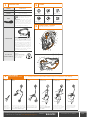 2
2
-
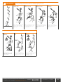 3
3
-
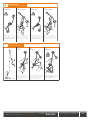 4
4
-
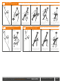 5
5
-
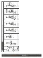 6
6
-
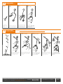 7
7
-
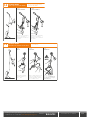 8
8
-
 9
9
-
 10
10
-
 11
11
-
 12
12
-
 13
13
-
 14
14
-
 15
15
-
 16
16
-
 17
17
-
 18
18
-
 19
19
-
 20
20
-
 21
21
-
 22
22
-
 23
23
-
 24
24


Climbing Technology 2K651 Instrucciones de operación
- Tipo
- Instrucciones de operación
en otros idiomas
Artículos relacionados
-
Climbing Technology 2D643 Instrucciones de operación
-
-
-
-
-
-
-
-
-
Otros documentos
-
 Outsunny 845-409V00WT Assembly Instructions
-
Petzl VERSO Technical Notice
-
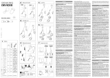 Trango Pyramid & Regulock Screw Manual de usuario
-
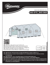 Outsunny 845-068 Assembly Instructions
-
-
-
Petzl KIT CORAX GRIGRI Sm’D Technical Notice
-
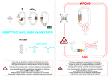 Kong Fast-Rubber Manual de usuario
-
 Outsunny 845-232GN Assembly Instructions
-
Petzl Simple Technical Notice


