
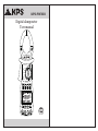
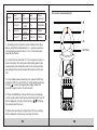
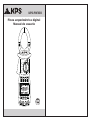
Digital clamp meter
User manual
KPS-PW300
~
~
kW
1 PHASE
Ø
1 PHASE
kW/Ø
3 PHASE
HARM
A~
V~
HARM
°
APS
RS232
HOLD REC
FS
LAG
LEAD
RST
CAL
USED
READ
MEMO
COSΦ
SINΦ
MAX MIN
VA
kWh
PEAK
%THD
kVA
Hz
HzA
PEAK
kWVAh
POWER CLAMP METER
Yrue RMS
Harmonic
AUTO RANGE
MODE I U READ
CLEARRS232
Watt
SET
COM/V2 EN61010-1
600V CAT III
V3V1
HOLD
OFF

Security requirements.............................................1
Safety instructions...................................................2
Safety signs .............................................................2
DeGeneral description ............................................2
Characteristic...........................................................3
Select wheel functions ...........................................6
Key functions ..........................................................7
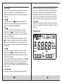
LCD screen.............................................................10
Operation Manual ..................................................12
Test data storage ...................................................21
Read saved data ...................................................22
RS232C communication interface .......................22
Input current and voltage.....................................23
Backlit display........................................................23
Auto off......... .........................................................23
Secure clamping diagram.....................................24
Power curve diagram ...........................................25
Low battery indication..........................................26
Replacing the batteries.........................................26
General specification............................................28
Technical specification..........................................28
Accessories ...........................................................31
Replacing the test leads.................... ...................32
Replacing the batteries.........................................32
CONTENTS CONTENTS

Security requirements
Please read the instruction manual carefully before using
the clamp and pay special attention to the "Warnings."
Please follow the instructions in the "Warnings".
1. Please be very careful when the test voltage is higher
than 30V AC, and take care that your fingers do not
exceed the protection barrier of the test leads.
2. Do not measure voltage higher than the permitted limit
values.
3. Before use, please check the clamp and test leads; do
not carry out measurements if the leads are bare, the
caliper housing is damaged, there is no LCD display, etc.
4. The requirements of the safety regulations are met
only when the clamp is used in conjunction with the
supplied test leads. In the event that the cables are
damaged and need to be replaced, it is necessary to use
others of the same model and identical technical
specifications.
5. Please never carry out voltage measurements if the
test leads are connected to a current output.
6. Please do not expose the clamp to strong light, high
temperature or humidity.
Warning
Before use, please read this instruction manual
carefully. Especially the safety contents!
01 02
Security instructions
This three-phase wattmeter is designed and manufactured
in accordance with the EN61010-1 safety standard and the
IEC1010-2-032 international safety specification and
meets the CATIII 600V AC double insulation safety
requirement.
Safety signs
Important safety information, see the instruction
manual.
High voltage risk
Ground
Double insulation (Category II safety
equipment)
Low battery indicator
CAT III (OVERVOLTAGE CATEGORY III): Measurement
category III is suitable for testing and measuring circuits
connected to the distribution part of the building's low
voltage installation.
General description
The 3-phase wattmeter is a portable, smart harmonic power
tester with both current and power measurement. The
instrument is composed of three channels including voltage,
current and power as well as a single micro chip and is
equipped with powerful software for measurement and data
processing functions; It can measure, calculate and display
voltage, current, active power, power factor, apparent power,
passive power, frequency and harmonic parameters, with
stable performance and ease of operation. The instrument is
especially suitable for measuring and

examination of on-site power equipment and power supply
circuits; With a small and lightweight portable clamp
structure, it can be easily carried by the user, making
measurements quick and easy. For single-phase / three-
phase power measurements, this instrument is the ideal
choice.
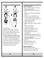
Characteristics
1. The clamp can be used to measure power, voltage,
current, peak value, phase, frequency, power factor,
phase angle, reactive factor, etc. single-phase / three-
phase circuits; automatic checking of the phase
sequence is possible for three-phase measurements.
2. True RMS Measurement - Accurate measurement is
possible even with strong distortion in the current
waveform.
3. A high speed and low consumption single chip
microprocessor is used and a sophisticated algorithm is
used, resulting in great speed and precision in obtaining
results and the possibility of measuring the distortion value
and up to the 20th harmonic.
4. It is equipped with a large memory
to record up to 100 groups of test parameters.
5. A recording interface is equipped and
RS232C communication and specialized graphics software
for WINDOWS.
6. Clip-type format, portable, lightweight and suitable for
transporte.
03 04
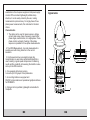
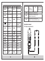
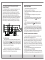
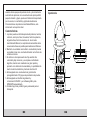
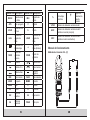
Appearance
1
2
3
4
5
8
6
7
~
~
kW
1 PHASE
Ø
1 PHASE
kW/Ø
3 PHASE
HARM
A~
V~
HARM
°
APS
RS232
HOLD REC
FS
LAG
LEAD
RST
CAL
USED
READ
MEMO
COSΦ
SINΦ
MAX MIN
VA
kWh
PEAK
%THD
kVA
Hz
HzA
PEAK
kWVAh
POWER CLAMP METER
Yrue RMS
Harmonic
AUTO RANGE
MODE I U READ
CLEARRS232
Watt
SET
COM/V2 EN61010-1
600V CAT III
V3V1
HOLD
OFF

05 06
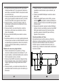
1. Size of the current jaw: Φ 50 mm.
2. HOLD key: data hold key; press the HOLD key, the last
reading on the screen will freeze and the “HOLD” symbol will
be displayed; press the HOLD key again and the clamp will
return to normal measurement mode.
3. Function selection wheel: selection wheel for choosing the
measurement function.
4. Function selection key: key to manage measurement
functions.
5. Input terminals:
Terminal Funtion
V1
Input terminal to measure the first phase;
use the yellow test lead for connection
COM/V2
Input terminal to measure the second
phase; use the black test lead for
connection.
Common terminal: ground input terminal for
all measurement functions; use the black
test lead for connection
V3
Input terminal to measure the third phase;
use the green test lead for connection
6. LCD display: 4-digit digital display; 7-segment LCD to
display measurement function, result, and unit symbol.
7. Trigger: press the trigger and the clamp will open;
release it and the clamp will close.
8. RS232C interface: the specialized optical-electrical
interface cable is used for online communication with the
PC, as well as for data logging and data trend curve on
the PC.
Select wheel functions
The function selector wheel is used for switching on and for
selecting the measurement function according to the
following table:
SymbolWheel position Functions
OFF OFF position To turn off the clamp
KW
(1 fase)
Active power
position
To measure active
power, etc.
Φ
(1 fase)
Single phase phase
angle check position
To measure the phase
angle, such as cos Φ
and sin Φ, etc.
KW/Φ
(3 fase)
Three-phase apparent
power position
To measure three-phase
apparent power, etc.
A~ AC current harmonics
check position
To measure harmonics
of AC current, etc.
V~
AC voltage
harmonics check
position
To measure AC
voltage harmonics,
etc.
Note:
When the caliper turns off automatically, be sure to turn the
wheel to the “OFF” position; turn on the clamp after 5
seconds.

Key functions
Description of the keys
SN Function selection key
1MODE: Mode select key - test
2SET: setting key
3I: current test key
4WATT: power test selection key
5U: voltage test key
6READ: data read key
7RS232: RS232C key
8CLEAR: memory clear key
9: tbacklight key
10 : increase key
11 : decrement key
12 REC/SAVE: data logging and storage key
13 HOLD: reading hold key
The following operations can be performed using the keys:
WATT key
In measurement mode, you can measure active power,
apparent power, power factor and phase angle and display
the results on the LCD screen by pressing the WATT key.
MODE key
In kW measurement mode, press the MODE key to toggle
between the active power and reactive power display; In A /
V ~ measurement mode, you can toggle between displaying
the total harmonic distortion ratio Fr and the harmonic
percentage.
07
SET key
In the measurement mode, you can press the SET key and
then the and keys , you can adjust the current and
voltage scale and then press the SET key again to return to
normal mode. This key also serves as a confirmation key
during storage and deletion.
U key
In measurement mode, you can press this key to check the
voltage in the circuit under test and show the measured
voltage on the screen.
READ key
In HOLD mode, you can press this key to display the stored
data; press this key again to return to normal mode.
I key
In measurement mode, you can press the I key to measure
the current in the circuit under test and display the current
measured by the clamp on the LCD screen.
RS232 key
In the measurement mode, you can press the RS232 key to
transfer the current results to the PC via the specific
interface cable supplied with the clamp for the purpose of
recording / printing data and data trend graph.
Before pressing the RS232 key for transfer
data, the RS232C interface cable must be connected to the
RS232C port of the clamp and to the COM port of the PC, to
perform the communication functions.
08

SAVE to display voltage, current, max / min power. which is
actually measured; In reading hold mode, press this key to
display the storage position; press the SET key again to
save the frozen data on the screen in memory. Up to 100
groups of data can be stored in the gripper.
HOLD key
After measurement, press this key to freeze the data on the
LCD screen; After shutdown, the data will be displayed.
LCD Screen
09 10
CLEAR key
In data reading mode, you can press the CLEAR key and
then the SET key to clear the test data stored in the clamp at
a specified position.
Key
You can press the key to turn the backlight on or off.
After being on for 20 seconds, it will turn off automatically.
Key
In the tension scale setting mode, you can press the key
to change the tension scale. During the harmonic check, you
can change the order of the harmonics.
When reading the stored data, you can press the key to
advance through memory locations and display them on the
LCD screen. With each press of the key, the search cursor
will advance one position on the previous data.
Key
In the current scale setting mode, you can press the key
to change the voltage scale. During the harmonic check, you
can change the order of the harmonics.
When reading the stored data, you can press the key to
go back through the memory locations and display them on
the LCD screen. With each press of the key, the search
cursor will go back one position on the previous data.
REC / SAVE key
In measurement mode, you can press the REC /
°
APS
RS232
HOLD REC
FS
LAG
LEAD
RST
CAL
USED
READ
MEMO
COSΦ
SINΦ
MAX MIN
VA
kWh
PEAK
%THD
kVA
Hz
HzA
PEAK
kWVAh

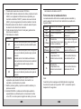
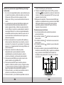
LCD symbol Description LCD symbol Description
RS232 Data
transference REC Data register
APS Auto OFF FFast
HOLD Read retention SSlow
LAG Phase
angle delay LEAD
Phase
angle Lead
Low battery
indication oPhase Angle
(Degrees)
SINΦ
Reverse
power factor COSΦ Power factor
RST triphasic Normal phase
Symbol C.A. Reverse phase
Lack of phase Negative
symbol
MIN Minimum value MAX Maximum value
USED Used MEMO Save
READ Read VVoltage
WWatts ACurrent
VAr Reactive
power Hz Frequency
VA Apparent
power PEAK Peak value
%Harmonic
percentage
High voltage
warning sign
%THD Total harmonic distortion ratio
H01F Total harmonic distortion ratio F
(relative to main wave)
H01r Total harmonic distortion ratio F
(relative to the actual effective value)
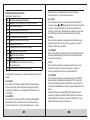
Operation manual
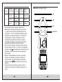
AC voltage measurement (V)
11 12
ACV

Position Input
terminal V1
Input
terminal V2
Input
terminal V3
Object
under test
V~
Toma V1 Toma V2/
COM N/A Monofásico
Toma V1 Toma V2/
COM N/A Bifásico
Toma V1 Toma V2/
COM Toma V3 Trifásico
1. According to the connection mode indicated in the table
above, place the thumbwheel in the V ~ position, select the
corresponding sockets for the V1, V2 or V3 terminals and
insert the test leads.
2. Connect the two test leads V1, V2 to the power source or
load to be tested. The clamp will automatically perform the
measurement and display the result on the screen and the
percentage of harmonics present will be shown on the next
line.
3. In the voltage measurement function, press the SET key
to display “AUTO V” and “AUTO A” on the display and press
the key to select the appropriate voltage scale and
press SET again to return to normal mode.
4. Press the MODE key to show the harmonic percentage
on the screen and the total harmonic distortion ratio F and R
will be displayed cyclically. Press the keys to display
the value of each harmonic.
5. When the input voltage is higher than 50V, the symbol ()
will be displayed on the screen, warning of the risk.
13
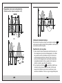
AC current measurement (A)
14
NEUTRAL
3
2
1

3. After connecting correctly, you can measure single phase
power (active power, power factor, apparent power, reactive
power, voltage, current, phase angle, peak value of voltage
and current and frequency).
4. The clamp will perform automatic measurement and
display the active power, and at the bottom of the screen it
will indicate the voltage / current value of the load tested;
Press the MODE key to display the reactive power value on
the LCD screen; Press the WATT key to show the apparent
power and the power factor (cosᴓ); Negative power factor
means that the tested load has a capacitive component.
5. The maximum active power measurement scale is
600kW; If this scale is exceeded, the “OL” symbol will be
displayed on the screen. If the voltage is higher than 600V or
the current is higher than 1000A, the “OL” symbol will be
displayed on the LCD.
1. Set the thumbwheel to position A ~.
2. Press the trigger to open the jaw, and then hug the lead
of the circuit to be measured. The measured current will
be displayed on the LCD screen.
3. Press the MODE key to display the percentage of
harmonics and the ratio of harmonic distortion F and r will
be displayed cyclically.
4. Press the keys to display the value of each
individual harmonic.
If the current through the measured cable is greater than
1000A (RMS), the symbol “OL” will be indicated instead of
the current value.
Notes:
1. You can select the AUTO / FIXED test frequency at 50 /
60Hz. When the input waveform fluctuates, the harmonic
values can be kept stable by selecting the Fixed 50/60 Hz
mode.
2. In the AUTO test frequency mode, the FFT calculation is
only performed when the frequency of the fundamental wave
is between 45 and 65 Hz. If that frequency is outside of that
range, harmonic analysis is not performed.
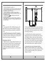
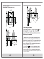
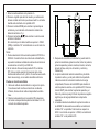
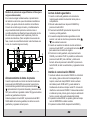
Single-phase circuit test
1. Clamp the power or charging cable with the clamp. If you
want to measure a specific phase of a three-phase system,
only wrap around the cable corresponding to that phase.
2. Set the thumbwheel to the KW position, select the
corresponding sockets for terminals V1 or V2 and insert the
test leads.
15
°
APS
RS232
HOLD REC
FS
LAG
LEAD
RST
CAL
USED
READ
MEMO
COSΦ
SINΦ
MAX MIN
VA
kWh
PEAK
%THD
kVA
Hz
HzA
PEAK
kWVAh
~
3 PHASE
1PHASE
1PHASE
HARM
HARM
Power supply
Load
Yellow
Black
600V~
MAX
600V~
MAX
~
16

6. The minimum input voltage is 50V and the minimum input
current is 2nd. If the values are lower than these limits,
“0.00kW” will be displayed as active power instead of the
actual value.
7. Press the SET key for AUTO mode and press the () / ()
keys to adjust the voltage and current ranges; Press the SET
key to return to normal mode.
8. Press the I key and the current value, peak current value
and frequency will be shown on the bottom line of the
display.
9. Press the U key and the voltage value, the peak voltage
value and the frequency will be shown on the bottom line of
the display.
10. Press the REC / SAVE key to display the MAX and MIN
values.
11. Reactive power is not a directly measured value; the
equation for its calculation is kVAr2 = kVA2-kW2; the value is
calculated by programming based on the measured voltage,
current and active power and is displayed on the LCD
screen.
Measurement of cosᴓ, sinᴓ and phase angle
1. Set the thumbwheel to position ᴓ (1 phase) and connect
the test leads to terminals V1 and V2.
2. The clamp will automatically measure and display the
value of power factor, voltage and current.
3. Press the WATT key to display the phase angle, power
factor (cosᴓ) and sinᴓ; A negative power factor means that
the measured load is capacitive in nature.
4. Press the I key and the current value, peak current and
frequency will be displayed on the bottom line of the display.
17
5. Press the U key and the voltage value, the voltage peak
and the frequency will be displayed on the bottom line of
the display.
6. Press the REC / SAVE key to display the MAX and MIN
values.
7. Press the SET key for AUTO mode and press the keys
- to adjust the measurement scale for voltage and
current; Press the SET key to return to normal mode.
8. After the measurement, press the HOLD key to keep the
reading on the screen and press the REC / SAVE key to
show the memory location where to save it and press the
SET key to confirm and return to the main menu.
Single-phase 3-wire circuit
The procedure for measuring power and power factor in
single-phase three-wire circuits is the same as for single-
phase two-wire circuits, where the black crocodile is
connected to the neutral line and the red crocodile and
the current jaw are connected. to the other two cables.
Power supply
Red
Black
Load
3 PHASE
1PHASE
1PHASE
HARM
Black
Red
1PHASE
18

Power measurement of three-phase loads (for balanced
load)
1. In the case of balanced loads, the procedure for
measuring power and power factor in 3-phase 4-wire circuits
is the same as for 3-phase 3-wire circuits and it is not
necessary to use the neutral line.
2. The measured three-phase total power parameters are
total active power, total reactive power, total apparent power,
and total power factor of the three-phase circuit. The clamp
cannot perform three-phase energy measurement. In the
case of balanced loads, the measured result is accurate
while the total power error will increase the greater the power
variation.
3. Set the thumbwheel to the kW / ᴓ (three-phase) position,
wrap the first phase wire with the jawbone and connect
terminal V1, terminal V2 and terminal V3 to active phases 1,
2 and 3 respectively of the three-phase load, without
connecting the neutral.
4. After connecting the test leads properly, the clamp will
perform the measurement automatically and display the
power, voltage, current and indicate if a phase is
disconnected.
5. Press the MODE key to display the reactive power value
on the LCD screen.
6. Press the WATT key to show the apparent power, the
power factor (cosᴓ), the phase angle and the sinᴓ; Negative
power factor means that the tested load has capacitive
characteristic.
7. Press the I key and the current value, peak current and
frequency will be displayed.
8. Press the U key and the voltage value, peak voltage and
frequency will be displayed.
9. Press the SET key for AUTO mode and press the keys
- to adjust the voltage and current measurement
ranges and then press SET again to return to normal mode.
10. After measurement. Press the HOLD key to keep the
reading on screen and press the REC / SAVE key to show
the memory location where to save it and press the SET key
to confirm and return to the main menu.
Phase sequence test
1PHASE
Power supply
Load
rojo
1. The clamp will automatically perform the phase sequence
test.
2. The symbol will be displayed indicating a normal
phase sequence.
3. The symbol will be indicated indicating a reverse
phase sequence.
4. The symbol will be indicated indicating that a phase
is disconnected.
5. During measurement, press the REC / SAVE key to
display the MAX and MIN values and record the results.
Then press the RS232 key to transfer the test results to
the PC via a communication cable.
Amarillo
Negro
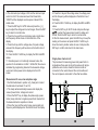
Measurement of power and power factor of three-
phase 3-wire circuits.
19 20

Power measurement of 3-phase 4-wire loads (for
unbalanced loads)
For unbalanced loads, the measurement procedure is the
same as for single-phase 2-wire systems and the
measurement mode is set to single-phase. Connect the
black crocodile to the neutral and simultaneously connect
both the current clamp and the yellow crocodile to the
different active lines of the circuit. In this way the power and
power factor of each line can be measured. (To check the
phase sequence, connect the voltage crocs to the three
lines one by one, without connecting any to the neutral).).
Test data storage
When the clamp is in the reading hold mode, press the
REC / SAVE key to display the memory location to save the
reading, press the keys to select the desired position,
and press the SET key to confirm saving. Up to 100 groups
of data can be stored in the gripper.
Before pressing the SET key, if you press the REC /
SAVE key, you will exit the save menu, the data will not be
saved and you will return to the previous menu.
Power supply
Load
Red
Yellow
Black
Red Black
Yellow
Yellow
Red Black
1PHASE
1PHASE
1PHASE
Measurement of power and power factor in 4-wire three-phase circuits.
Read saved data
1. When a data is stored in the memory of
the clamp can read it for checking.
2. Set the thumbwheel to the SEARCH position and press
the HOLD key.
3. Press the READ key to display the memory location
and the saved data.
4. If you need to check the data stored in another position
or the harmonic level, press the keys to make the
selection.
5. When the harmonic level data is displayed, press the
WATT key and then the keys to select the record
number.
6. To delete a saved data, just press the CLEAR key and
“CLR” will be displayed on the screen; then press the SET
key to confirm and the data will be erased. Before pressing
the SET key, if you press the CLEAR key, the data will not
be erased and you will return to the previous menu.
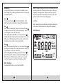
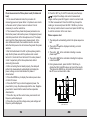
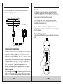
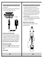
RS232C communication interface
1. Insert the RS232C communication cable into the clamp
terminal and turn it clockwise to fix it to
the clamp; Connect the RS232C plug on the other end of the
cable to the COM port of the PC, and you can do real-time
data transfer to the PC through the RS232C communication
interface. If you want to disconnect the cable from the clamp,
first turn the plug counterclockwise and when it loosens, pull it
out of the terminal.
2. If you press the RS232 key, the measured data can be
recorded in real time with WINDOWS.
3. If you press the HOLD key, then the READ key and finally
the RS232 key, the saved data can be downloaded to the PC.
21 22

4. With the software you can motorize the data records in
real time, make graphs, print ... etc.
Input current and voltage
During power measurement, if the input voltage is
higher than 600V (RMS) or the input current is
higher than 1000A (RMS), the “OL” symbol will be
displayed on the screen and the bar graph will be
complete. When the input voltage is higher than
50V, the symbol will be displayed on the
screen, prompting you to pay attention to safety.
Backlit display
By pressing the key , the backlight will turn on
and turn off automatically about 20 seconds later.
232SR -C
FRETNI ECA
LACITPO
600V
MAX
~
3
RS232OPTICAL INTERFACE
计算机
PC COM
(RS232C connection diagram)
Auto off
1. If there is no function change or any key press for 10
minutes, the gripper will automatically turn off. After the
caliper turns off, be sure to set the thumbwheel to the OFF
position; turn on the clamp after 5 seconds.
2. By holding down the SET and CLEAR keys while
turning on the clamp, you will be able to deactivate the
automatic shutdown function.
3. The auto power off function will be disabled in the
MAX / MIN recording mode and while communicating with
the PC software.
Secure clamping diagram
Using the wrist strap can prevent unexpected drops of the
clip..
IEC1010-1 IEC1010-2-032
600V CAT.IIIPOLLUTION DEGREE 2
WARNING
OPEN
PLEASE READ MANUAL FOR SAFETY.TO AVOID
ELECTRICAL SHOCK NEVER CONNECT THE TEST
LEADS TO THE INPUT JACKS WHICH ARE NOT
FORRELATED MEASURING AND REMOVE ALL
INPUTS BEFORE OPENING CASE.
BATTERIES : 4 X 1.5 V SIZE AA
23 24

Low battery indication
If the battery voltage is low, the symbol will
be displayed in the upper right corner of the
screen. Then the batteries need to be replaced.
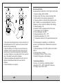
Replacing the batteries
1. Before opening the back cover to replace the batteries,
please make sure that the clamp is turned off and the test
leads are not connected to any circuit to avoid electric shock;
Before using the clamp again, please make sure the back
cover is fully attached. Only batteries of the same model or
electrical specification can be used.
2. If the symbol “ ” is shown on the screen, it means
that the battery voltage is lower than the minimum value to
ensure the error limits of the measurements and it will be
necessary to change them. Please follow the steps below to
replace the batteries:
Power curve diagram
(Active power = apparent power x FP)
25 26

3. Disconnect the test leads from the circuits under test, turn
the thumbwheel to the “OFF” position, and remove the test
leads from the input terminals.
4. Open the battery cover, taking into account its opening
mechanism; Insert a coin into the notch on the cover and
press the coin to open the locking buckle. Finally slide the
cover down. Please do not use sharp tools to force open the
cap, or the caliper housing will be damaged.
5. Remove the batteries and replace them with 4 new 1.5V
batteries. New batteries should not be used with old
batteries.
6. Close the battery cover properly.
General specification
Complies with IEC / EN 61010-1 CATII 1000V, CAT III 600V.
1. Maximum voltage: 600V AC RMS.
2. Display mode: LCD screen, maximum reading: 6000.
3. Scale selection: Fully automatic scale selection.
4. Frequency detection: automatic (When harmonics are
high, it is better to use manual adjustment to check the
frequency in order to ensure the stability of the reading).
5. Saturation display: “OL”.
6. Data hold: “HOLS” is displayed on the LCD screen.
7. Power supply: 4 AA 1.5V batteries.
8. Power consumption: 250 mW.
9. Storage temperature: -20ºC ~ 70ºC.
10. Operating temperature: 0ºC ~ 40ºC.
11. Temperature coefficient: 0.05x (specified precision) per
ºC.
12. Electromagnetic Compatibility: In a 3VM RF field,
precision = specified precision. Otherwise the precision is
not specified.
13. Operating altitude: CAT III 600V: 2000m; CAT II 600V:
3000 m.
14. Storage altitude: 12,000m.
15. Dimensions: 300mm x 103mm x 51mm.
16. Weight: 500 gr approx. (with batteries).
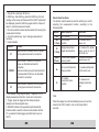
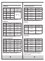
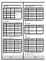
Technical specification
Accuracy: ± (% of reading + graduation) Ambient
temperature: 18ºC ~ 28ºC, humidity 80% Frequency
for voltage, current: 45Hz ~ 65Hz
27 28

Three-phase active power (W)
Escala Precisión Resolución
3kVA ±(3%+5) 0.001kVA
12kVA ±(3%+5) 0.01kVA
30kVA ±(3%+5) 0.01kVA
120kVA ±(3%+5) 0.1kVA
150kVA ±(3%+5) 0.1kVA
600kVA ±(3%+5) 0.1kVA
Minimum test current: 2A; Minimum test voltage: 50V
Power factor
Escala Precisión Resolución
0.3~1
Capacitivo ±(0.02%+2) 0.001
0.3~1
Inductivo ±(0.02%+2) 0.001
Minimum test current: 2A; Minimum test voltage: 50V
Reactive power
Escala Precisión Resolución
3kVAr ±(3%+5) 0.001kVAr
12kVAr ±(3%+5) 0.01kVAr
30kVAr ±(3%+5) 0.01kVAr
120kVAr ±(3%+5) 0.1kVAr
150kVAr ±(3%+5) 0.1kVAr
600kVAr ±(3%+5) 0.1kVAr
Minimum test current: 2A; Minimum test voltage: 50V. The
reactive power is calculated according to the measured
values of V, A and kW.
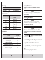
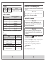
AC RMS voltage
Escala Precisión Resolución Impedancia de
entrada
80V ±(1%+5) 0.1V
1 MΩ // 10 pF
180V ±(1%+5) 0.01V
400V ±(1%+5) 1V
600V ±(1%+5) 1V
Maximum allowed overload voltage: 750V (RMS)
AC RMS current
Escala Precisión Resolución
20A ±(2%+5) 0.01A
40A ±(2%+5) 0.01A
100A ±(2%+5) 0.1A
200A ±(2%+5) 0.1A
450A ±(2%+5) 1A
1000A ±(2%+5) 1A
Maximum allowed overload current: 1200A
Single phase active power (W)
Escala Precisión Resolución
30kW ±(3%+5) 0.01kW
60kW ±(3%+5) 0.01kW
120kW ±(3%+5) 0.1kW
150kW ±(3%+5) 0.1kW
300kW ±(3%+5) 0.1kW
600kW ±(3%+5) 0.1kW
Minimum test current: 2A; Minimum test voltage: 50V
29 30

31
Frequency
Escala Resolución Precisión
30~1000Hz 0.1Hz 0.5%+1 graduación
Minimum test voltage: 50V
Harmonics test
Orden del armónico Precisión de la tensión del
armónico
1±(3.0%+10)
2-6 ±(3.5%+10)
7-8 ±(4.5%+10)
9-10 ±(5.0%+10)
11-15 ±(7%+10)
16-20 ±(10%+10)
Minimum test current: 2A; Minimum test voltage: 50V
Accessories
Artículo Cantidad
Manual de instrucciones abreviado 1
Pilas AA 1.5V 4
Cables de prueba 1
Cables con cocodrilo 3
Cable de comunicación RS232 1
CD con software PC 1
Maletín de transporte 1
32
Replacing the test leads
Replace the test leads if they have arrived damaged or
peeled.
Warning
Use test leads that comply with EN 61010-31, CAT III
600V or higher.
Replacing the batteries
Warning
To avoid electric shock, be sure to remove the test
leads from the circuit to be measured before opening
the battery cover of the clamp.
Warning
Do not mix old and new batteries. Do not mix alkaline,
normal (carbon-zinc) or rechargeable (ni-cad, ni-mh, etc)
batteries.
1. If the symbol “ ” appears on the display, it means that
the batteries must be replaced.
2. Loosen the fixing screw of the battery cover and remove it.
3. Replace the exhausted batteries with new ones.
4. Replace the battery cover and fix it in its original position.
Note:
Do not reverse the polarity of the batteries.

Pinza amperimétrica digital
Manual de usuario
KPS-PW300
~
~
kW
1 PHASE
Ø
1 PHASE
kW/Ø
3 PHASE
HARM
A~
V~
HARM
°
APS
RS232
HOLD REC
FS
LAG
LEAD
RST
CAL
USED
READ
MEMO
COSΦ
SINΦ
MAX MIN
VA
kWh
PEAK
%THD
kVA
Hz
HzA
PEAK
kWVAh
POWER CLAMP METER
Yrue RMS
Harmonic
AUTO RANGE
MODE I U READ
CLEARRS232
Watt
SET
COM/V2 EN61010-1
600V CAT III
V3V1
HOLD
OFF

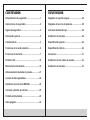
Requirimientos de seguridad .................................1
Instrucciones de seguridad ....................................2
Signos de seguridad ...............................................2
Descripción general ................................................2
Características .........................................................3
Funciones de la rueda selectora ............................6
Funciones de las teclas ..........................................7
Pantalla LCD ..........................................................10
Manual de funcionamiento ...................................12
Almacenamiento de datos de prueba ..................21
Lectura de datos guardados ................................22
Interfaz de comunicación RS232C .......................22
Corriente y tensión de entrada.............................23
Pantalla retroiluminada .........................................23
Auto apagado .........................................................23
Diagrama de sujeción segura...............................24
Diagrama de la curva de potencia .......................25
Indicación de batería baja.....................................26
Sustitución de las pilas.........................................26
Especicación general..........................................28
Especicación técnica ..........................................28
Accesorios .............................................................31
Sustitución de los cables de prueba ...................32
Sustitución de las pilas.........................................32
CONTENIDOS CONTENIDOS

Requerimientos de seguridad
Por favor, lea cuidadosamente el manual de instrucciones
antes de usar la pinza y preste especial atención a las
“Advertencias”. Por favor, siga las instrucciones de las
“Advertencias”.
1. Por favor, sea muy cuidadoso cuando la tensión de
prueba sea superior a 30V AC, y cuide que sus dedos
no sobrepasen la barrera de protección de las puntas de
prueba.
2. No mida tensión superior a los valores límites permitidos.
3. Antes del uso, por favor compruebe la pinza y los cables
de prueba; no lleve a cabo mediciones si los cables están
desnudos, la carcasa de la pinza está dañada, no hay
pantalla LCD, etc…
4. Se cumplen los requerimientos de las normas de
seguridad sólo cuando la pinza es usada junto con los
cables de prueba suministrados. En el caso de que
los cables estén dañados y necesite reemplazarlos,
se requiere utilizar otros del mismo modelo e idénticas
especicaciones técnicas.
5. Por favor, nunca lleve a cabo medidas de tensión si las
puntas de prueba están conectadas a una salida de
corriente.
6. Por favor, no exponga la pinza a un fuerte luz, alta
temperatura o humedad.
Advertencia
Antes del uso, lea detenidamente este manual de
instrucciones. ¡Especialmente los contenidos de
seguridad!
01 02
Instrucciones de seguridad
Esta pinza vatimétrica trifásica está diseñada y fabricada
de acuerdo a la normativa de seguridad EN61010-1 y a la
especicación internacional de seguridad IEC1010-2-032 y
cumple con el requisito de seguridad de doble aislamiento
CATIII 600V AC.
Signos de seguridad
Información importante de seguridad, consulte el
manual de instrucciones.
Riesgo de tensión elevada
Tierra
Doble aislamiento (Equipo de seguridad de
categoría II)
Indicador de batería baja
CAT III (CATEGORIA DE SOBRETENSIÓN III): La categoría
de medición III es adecuada para la comprobación y
medición de circuitos conectados a la parte de distribución
de la instalación de baja tensión del edicio.
Descripción general
La pinza vatimétrica trifásica es un comprobador inteligente
de potencia armónica, portátil, con medición tanto de
corriente como de potencia. El instrumento está compuesto
por tres canales incluyendo tensión, corriente y potencia así
como de micro chip sencillo y es equipado con un potente
software para las funciones de medición y procesamiento
de datos; puede medir, calcular y mostrar tensión, corriente,
potencia activa, factor de potencia, potencia aparente,
potencia pasiva, frecuencia y parámetros armónicos, con
una actuación estable y sencillez de funcionamiento. El
instrumento es especialmente adecuado para la medida y

examen de los equipos de potencia in-situ y los circuitos de
suministro de potencia; con una estructura de pinza portátil,
pequeño tamaño y ligera, puede ser fácilmente transportada
por el usuario, lo cual facilita y agiliza las mediciones.
Para mediciones de potencia monofásica/trifásica, este
instrumento es la opción ideal.
Características
1. La pinza puede ser utilizada para medir potencia, tensión,
corriente, valor pico, fase, frecuencia, factor de potencia,
ángulo de fase, factor de reactiva, etc. de circuitos
monofásicos/trifásicos; la comprobación automática de la
secuencia de fases es posible para mediciones trifásicas.
2. Medición en verdadero valor ecaz: una medición precisa
es posible incluso con una fuerte distorsión en la forma de
onda de corriente.
3. Se utiliza un microprocesador de chip sencillo alta
velocidad y bajo consumo y se emplea un sosticado
algoritmo, dando como resultado una gran rapidez y
precisión en la obtención de resultados y la posibilidad de
medir el valor de distorsión y hasta el armónico 20.
4. Está equipada con una memoria de gran tamaño
para grabar hasta 100 grupos de parámetros de prueba.
5. Está equipada un interfaz de grabación y
comunicación RS232C y un software gráco para
WINDOWS especializado.
6. Formato tipo pinza, portátil, ligera y adecuada para el
transporte.
03 04
Apariencia
1
2
3
4
5
8
6
7
~
~
kW
1 PHASE
Ø
1 PHASE
kW/Ø
3 PHASE
HARM
A~
V~
HARM
°
APS
RS232
HOLD REC
FS
LAG
LEAD
RST
CAL
USED
READ
MEMO
COSΦ
SINΦ
MAX MIN
VA
kWh
PEAK
%THD
kVA
Hz
HzA
PEAK
kWVAh
POWER CLAMP METER
Yrue RMS
Harmonic
AUTO RANGE
MODE I U READ
CLEARRS232
Watt
SET
COM/V2 EN61010-1
600V CAT III
V3V1
HOLD
OFF

05 06
1. Tamaño del maxilar de corriente: Φ 50 mm.
2. Tecla HOLD: tecla de retención de datos; presione la tecla
HOLD, se congelara la última lectura en pantalla y se
mostrará el símbolo “HOLD”; presione de nuevo la tecla
HOLD y la pinza regresará al modo de medición normal.
3. Rueda de selección de función: rueda de selección para
la elección de la función de medición.
4. Tecla de selección de función: tecla para gestionar las
funciones de medición.
5. Terminales de entrada:
Terminal Función
V1
Terminal de entrada para medir la primera
fase; use el cable de prueba amarillo para
la conexión
COM/V2
Terminal de entrada para medir la segunda
fase; use el cable de prueba negro para la
conexión.
Terminal común: terminal de entrada de
tierra para todas las funciones de medición;
use el cable de prueba negro para la
conexión
V3
Terminal de entrada para medir la tercera
fase; use el cable de prueba verde para la
conexión
6. Pantalla LCD: pantalla digital de 4 dígitos; LCD de 7
segmentos para mostrar la función de medición, el
resultado y el símbolo de la unidad.
7. Gatillo: pulse el gatillo y la pinza se abrirá; suéltelo y la
pinza se cerrará.
8. Interfaz RS232C: el cable de interfaz óptico-eléctrico
especializado es utilizado para la comunicación online
con el PC, así como para el registro de datos y la curva
de tendencia de datos en el PC.
Funciones de la rueda selectora
La rueda selectora de función es usada para el encendido y
para la selección de la función de medición de acuerdo a la
siguiente tabla:
Símbolo Posición de la rueda Funciones
OFF Posición de apagado Para apagar la pinza
KW
(1 fase)
Posición de potencia
activa
Para medir potencia
activa, etc.
Φ
(1 fase)
Posición de
comprobación de ángulo
de fase monofásico
Para medir el ángulo de
fase, como cos Φ y sen
Φ, etc.
KW/Φ
(3 fases)
Posición de potencia
aparente trifásica
Para medir potencia
aparente trifásica, etc.
A~
Posición de
comprobación de
armónicos de corriente
AC
Para medir armónicos
de corriente AC, etc.
V~
Posición de
comprobación de
armónicos de tensión
AC
Para medir armónicos
de tensión AC, etc.
Nota:
Cuando la pinza se apague automáticamente, asegúrese
de colocar la rueda en la posición “OFF”; encienda la pinza
después de 5 segundos.

Funciones de las teclas
Descripción de las teclas
SN Tecla de selección de función
1MODE: Tecla de selección de modo – prueba
2SET: tecla de ajuste
3I: tecla de prueba de corriente
4WAT T: tecla de selección de la prueba de potencia
5U: tecla de prueba de tensión
6READ: tecla de lectura de datos
7RS232: tecla RS232C
8CLEAR: tecla de borrado de memoria
9: tecla de retroiluminación
10 : tecla de incremento
11 : tecla de decremento
12 REC/SAVE: tecla de registro de datos y
almacenamiento
13 HOLD: tecla de retención de lecturas
Las siguientes operaciones se pueden realizar mediante las
teclas:
Tecla WATT
En el modo de medición, puede medir la potencia activa,
potencia aparente, factor de potencia y ángulo de fase y
muestra los resultados en la pantalla LCD al presionar la
tecla WATT.
Tecla MODE
En el modo de medición de kW, presione la tecla MODE
para alternar entre la visualización de potencia activa y
potencia reactiva; En el modo de medición A/V~, puede
07
alternar entre la visualización del ratio de distorsión
armónica total Fr y el porcentaje armónico.
Tecla SET
En el modo de medición, puede presionar la tecla SET y
luego las teclas y puede ajustar la escala de corriente
y tensión y luego presionar de nuevo la tecla SET para
volver al modo normal. Esta tecla sirve también como tecla
de conrmación durante el almacenamiento y borrado.
Tecla U
En el modo de medición, puede presionar esta tecla para
comprobar la tensión en el circuito a prueba y mostrar la
tensión medida en la pantalla.
Tecla READ
En el modo HOLD, puede presionar esta tecla para mostrar
los datos almacenados; presione otra vez esta tecla para
volver al modo normal.
Tecla I
En el modo de medición, puede presionar la tecla I para
medir la corriente en el circuito a prueba y mostrar la
corriente medida por la pinza en la pantalla LCD.
Tecla RS232
En el modo de medición, puede presionar la tecla RS232
para transferir los resultados actuales al PC a través del
cable de interfaz especíco suministrado con la pinza con
el objeto de grabar/imprimir datos y graco de tendencia de
datos.
Antes de presionar la tecla RS232 para la transferencia
de datos, el cable de interfaz RS232C debe conectarse al
puerto RS232C de la pinza y al puerto COM del PC, para
realizar las funciones de comunicación.
08

SAVE para mostrar la tensión, corriente, potencia máx./
mín. que es actualmente medida; En el modo de retención
de lecturas, presione esta tecla para mostrar la posición
de almacenamiento; presione la tecla SET de nuevo para
guardar el dato congelado en pantalla en la memoria. Se
pueden almacenar hasta 100 grupos de datos en la pinza.
Tecla HOLD
Después de la medición, presione esta tecla para congelar
el dato en la pantalla LCD; después del apagado, el dato se
mostrará.
Pantalla LCD
09 10
Tecla CLEAR
En el modo de lectura de datos, puede presionar la tecla
CLEAR y a continuación la tecla SET para borrar los
datos de prueba almacenados en la pinza en una posición
especica.
Tecla
Puede presionar la tecla para activar o desactivar la
retroiluminación. Después de estar encendida durante 20
segundos, se apagará automáticamente.
Tecla
En el modo de ajuste de la escala de tensión, puede
presionar la tecla para cambiar la escala de tensión.
Durante la comprobación de armónicos, puede cambiar el
orden de los armónicos.
Al leer los datos almacenados, puede presionar la tecla
para avanzar a través de las posiciones de memoria y
mostrarlas en la pantalla LCD. Con cada pulsación de la
tecla, el cursor de búsqueda avanzara una posición sobre el
dato anterior.
Tecla
En el modo de ajuste de la escala de corriente, puede
presionar la tecla para cambiar la escala de tensión.
Durante la comprobación de armónicos, puede cambiar el
orden de los armónicos.
Al leer los datos almacenados, puede presionar la tecla
para retroceder a través de las posiciones de memoria y
mostrarlas en la pantalla LCD. Con cada pulsación de la
tecla, el cursor de búsqueda retrocederá una posición sobre
el dato anterior.
Tecla REC/SAVE
En el modo de medición, puede presionar la tecla REC/
°
APS
RS232
HOLD REC
FS
LAG
LEAD
RST
CAL
USED
READ
MEMO
COSΦ
SINΦ
MAX MIN
VA
kWh
PEAK
%THD
kVA
Hz
HzA
PEAK
kWVAh

Símbolo LCD Descripción Símbolo LCD Descripción
RS232 Transferencia
de datos REC Registro de
datos
APS Auto apagado FRápido
HOLD Retención de
lectura SLento
LAG
Retraso de
ángulo de
fase
LEAD
Adelanto de
ángulo de
fase
Indicación de
batería baja oÁngulo de
fase (Grados)
SINΦ
Factor de
potencia
inverso
COSΦ Factor de
potencia
RST Trifásico Fase normal
Símbolo C.A. Fase inversa
Falta de fase Símbolo
negativo
MIN Valor mínimo MAX Valor máximo
USED Ocupado MEMO Guardar
READ Leer VTensión
WVatios ACorriente
VAr Potencia
reactiva Hz Frecuencia
VA Potencia
aparente PEAK Valor pico
%Porcentaje
armónico
Signo de
advertencia
de alta
tensión
%THD Relación de distorsión armónica total
H01F Relación de distorsión armónica total F
(relativa a la onda principal)
H01r Relación de distorsión armónica total F
(relativa al valor real efectivo)
Manual de funcionamiento
Medición de la tensión C.A. (V)
11 12
ACV

Posición
Terminal
de entrada
V1
Terminal
de entrada
V2
Terminal
de entrada
V3
Objeto a
prueba
V~
Toma V1 Toma V2/
COM N/A Monofásico
Toma V1 Toma V2/
COM N/A Bifásico
Toma V1 Toma V2/
COM Toma V3 Trifásico
1. De acuerdo al modo de conexión indicado en la
tabla superior, sitúe la rueda selectora en la posición
V~, seleccione las tomas correspondientes para los
terminales V1, V2 o V3 e inserte los cables de prueba.
2. Conecte los dos cables de prueba V1, V2 a la fuente
de alimentación o carga a ser probada. La pinza
automáticamente realizará la medición y mostrará
en pantalla el resultado y el porcentaje de armónicos
presentes será mostrada en la línea siguiente.
3. En la función de medición de tensión, presione la tecla
SET para mostrar “AUTO V” y “AUTO A” en la pantalla y
presione la tecla para seleccionar la escala de tensión
adecuada y vuelva a presionar SET para regresar al
modo normal.
4. Presione la tecla MODE para mostrar el porcentaje
armónico en la pantalla y la relación de distorsión
armónica total F y R serán mostradas cíclicamente.
Presione la tecla / para mostrar el valor de cada
armónico.
5. Cuando la tensión de entrada es superior a 50V, el
símbolo () será mostrado en pantalla, advirtiendo del
riesgo.
13
Medición de corriente C.A. (A)
14
NEUTRAL
3
2
1

3. Después de conectarlo correctamente, puede medir la
potencia monofásica (potencia activa, factor de potencia,
potencia aparente, potencia reactiva, tensión, corriente,
ángulo de fase, valor pico de tensión y corriente y
frecuencia).
4. La pinza realizará la medición automática y mostrará
la potencia activa, y en la parte inferior de la pantalla
indicará el valor de la tensión/corriente de la carga
comprobada; Presione la tecla MODE para mostrar el
valor de potencia reactiva en la pantalla LCD; Presione
la tecla WATT para mostrar la potencia aparente y el
factor de potencia (cosᴓ); El factor de potencia negativo
signica que la carga probada tiene componente
capacitiva.
5. La escala máxima de medida de la potencia activa es
de 600kW; Si esta escala es excedida, se mostrará el
símbolo “OL” en pantalla. Si la tensión es superior a
600V o la corriente es superior a 1000A, se mostrará el
símbolo “OL” en la pantalla LCD.
1. Sitúe la rueda selectora en la posición A~.
2. Presione el gatillo para abrir el maxilar y a continuación
abrace el cable del circuito que desee medir. La corriente
medida será mostrada en la pantalla LCD.
3. Presione la tecla MODE para mostrar el porcentaje de
armónicos y se mostrarán cíclicamente la relación de
distorsión armónica F y r.
4. Presione las teclas / para mostrar el valor de cada
armónico individual.
Si la corriente por el cable medido es superior a 1000A
(RMS), el símbolo “OL” será indicado en vez del valor de
corriente.
Notas:
1. Puede seleccionar la frecuencia de prueba AUTO/FIJA a
50/60Hz. Cuando la forma de onda de la entrada uctúa,
se pueden mantener estables los valores de armónicos si
se selecciona el modo Fijo a 50/60 Hz.
2. En el modo de frecuencia de prueba AUTO, el cálculo
FFT sólo se realiza cuando la frecuencia de la onda
fundamental está entre 45 y 65 Hz. Si esa frecuencia está
fuera de ese rango, no se realiza el análisis armónico.
Prueba en circuito monofásico
1. Abrace el cable de la alimentación o carga con la pinza.
Si se desea medir una fase concreta de un sistema
trifásico, abrace sólo el cable correspondiente a dicha
fase.
2. Sitúe la rueda selectora en la posición KW, seleccione
las tomas correspondientes para los terminales V1 o V2
e inserte los cables de prueba.
15
°
APS
RS232
HOLD REC
FS
LAG
LEAD
RST
CAL
USED
READ
MEMO
COSΦ
SINΦ
MAX MIN
VA
kWh
PEAK
%THD
kVA
Hz
HzA
PEAK
kWVAh
~
3 PHASE
1PHASE
1PHASE
HARM
HARM
Alimentación
Carga
Amarillo
Negro
600V~
MAX
600V~
MAX
~
16

6. La tensión mínima de entrada es de 50V y la corriente
mínima de entrada de 2ª. Si los valores son inferiores a
esos límites, se mostrará “0.00kW” como potencia activa
en vez del valor real.
7. Presione la tecla SET para el modo AUTO y presione las
teclas ()/() para ajustar la escalas de tensión y corriente;
Presione la tecla SET para regresar al modo normal.
8. Presione la tecla I y el valor de corriente, el valor de
corriente pico y la frecuencia se mostrarán en la línea
inferior de la pantalla.
9. Presione la tecla U y el valor de tensión, el valor de
tensión pico y la frecuencia se mostrarán en la línea
inferior de la pantalla.
10. Presione la tecla REC/SAVE para mostrar los valores
MAX y MIN.
11. La potencia reactiva no es un valor medido directamente;
la ecuación para su cálculo es kVAr2=kVA2-kW2; el valor
es calculado por programación en función de la tensión,
corriente y potencia activa medida y se muestra en la
pantalla LCD.
Medición de cosᴓ, senᴓ y ángulo de fase
1. Sitúe la rueda selectora en la posición ᴓ (1 fase) y
conecte los cables de prueba a los terminales V1 y V2.
2. La pinza medirá y mostrará automáticamente el valor de
factor de potencia, tensión y corriente.
3. Presione la tecla WATT para mostrar el ángulo de fase,
factor de potencia (cosᴓ) y senᴓ; Un factor de potencia
negativo signica que la carga medida tiene carácter
capacitivo.
4. Presione la tecla I y se mostrará en la línea inferior de
la pantalla el valor de corriente, el pico de corriente y la
frecuencia.
17
5. Presione la tecla U y se mostrará en la línea inferior de
la pantalla el valor de tensión, el pico de tensión y la
frecuencia.
6. Presione la tecla REC/SAVE para mostrar los valores
MAX y MIN.
7. Presione la tecla SET para el modo AUTO y presione
las teclas / para ajustar la escala de medida para
tensión y corriente; Presione la tecla SET para regresar
al modo normal.
8. Después de la medición, presione la tecla HOLD para
mantener la lectura en pantalla y presione la tecla REC/
SAVE para mostrar la posición de memoria donde
guardarla y presione la tecla SET para conrmar y
regresar el menú principal.
Circuito monofásico de 3 hilos
El procedimiento para medir la potencia y el factor de
potencia en circuitos monofásicos a tres hilos es el mismo
que para circuitos monofásicos a dos hilos, donde el
cocodrilo negro es conectado a la línea de neutro y el
cocodrilo rojo y el maxilar de corriente están conectados a
los otros dos cables.
Alimentación
Rojo
Negro
Carga
3 PHASE
1PHASE
1PHASE
HARM
Negro
Rojo
1PHASE
18

Medición de potencia de cargas trifásicas (para carga
balanceada)
1. En el caso de cargas balanceadas, el procedimiento para
la medición de potencia y factor de potencia en circuitos
trifásicos de 4 hilos es el mismo que para circuitos
trifásicos de 3 hilos y no es necesario utilizar la línea de
neutro.
2. Los parámetros de potencia total trifásica medidos son
la potencia activa total, la potencia reactiva total, la
potencia aparente total y el factor de potencia total del
circuito trifásico. La pinza no puede realizar la medición
de energía trifásica. En el caso de cargas balanceadas,
el resultado medido es preciso mientras que el error de
la potencia total se incrementará cuanto mayor sea la
variación de potencia.
3. Sitúe la rueda selectora en la posición kW/ᴓ (trifásico),
abrace el primer cable de fase con el maxilar y conecte
el terminal V1, el terminal V2 y el terminal V3 a las fases
activas 1, 2 y 3 respectivamente de la carga trifásica, sin
conectar el neutro.
4. Después de conectar los cables de prueba
adecuadamente, la pinza realizará la medición
automáticamente y mostrará la potencia, tensión,
corriente e indicara si una fase esta desconectada.
5. Presiones la tecla MODE para mostrar el valor de la
potencia reactiva en la pantalla LCD.
6. Presiones la tecla WATT para mostrar la potencia
aparente, el factor de potencia (cosᴓ), el ángulo de fase
y el senᴓ; El factor de potencia negativo signica que la
carga comprobada tiene característica capacitiva.
7. Presione la tecla I y se mostrará en pantalla el valor de
corriente, la corriente pico y la frecuencia.
8. Presione la tecla U y se mostrará en pantalla el valor de
tensión, la tensión pico y al frecuencia.
9. Presione la tecla SET para el modo AUTO y presione
las teclas / para ajustar las escalas de medición de
tensión y corriente y luego presione SET de nuevo para
regresar al modo normal.
10. Después de la medición. Presione la tecla HOLD para
mantener en pantalla la lectura y presione la tecla REC/
SAVE para mostrar la posición de memoria donde
guardarla y presione la tecla SET para conrmar y
regresar al menú principal.
Prueba de secuencia de fases
1. La pinza automáticamente realizará la prueba de
secuencia de fases.
2. Se mostrar el símbolo
RST
indicando una secuencia de
fases normal.
3. Se indicara el símbolo
RST
indicando una secuencia de
fases inversa.
4. Se indicara el símbolo
RST
indicando que una fase está
desconectada.
5. Durante la medición, presione la tecla REC/SAVE para
mostrar los valores MAX y MIN y registrar los resultados.
Luego, presione la tecla RS232 para transferir los
resultados de la prueba al PC a través de un cable de
comunicación.
1PHASE
Alimentación
Carga
rojo
Amarillo
Negro
Medición de potencia y factor de potencia de circuitos
trifásicos a 3 hilos.
19 20

Medición de potencia de cargas trifásicas a 4 hilos (para
cargas no balanceadas)
En el caso de cargas no balanceadas, el procedimiento
de medición es el mismo que el de sistemas monofásicos
a 2 hilos y se ajusta el modo de medición al monofásico.
Conecte el cocodrilo negro al neutro y simultáneamente
vaya conectando tanto la pinza de corriente como el
cocodrilo amarillo a las diferentes líneas activas del circuito.
De este modo se pueden medir la potencia y factor de
potencia de cada línea. (Para comprobar la secuencia de
fase, conecte los cocodrilos de tensión a las tres líneas una
a una, sin conectar ninguno al neutro).
Almacenamiento de datos de prueba
Cuando la pinza está en el modo de retención de lecturas,
presione la tecla REC/SAVE para mostrar la posición de
memoria donde guardar la lectura, presione las teclas /
para seleccionar la posición deseada y presione la tecla
SET para conrmar el guardado. Hasta 100 grupos de datos
pueden ser guardados en la pinza.
Antes de presionar la tecla SET, si presiona la tecla REC/
SAVE saldrá del menú de guardado, los datos nos serán
guardados y regresara al menú previo.
Alimentación
Carga
Rojo
Amarillo
Negro
Negro
Rojo
Amarillo
Amarillo
Negro
Rojo
1PHASE
1PHASE
1PHASE
Medición de potencia y factor de potencia en circuitos trifásicos a 4 hilos.
Lectura de datos guardados
1. Cuando un dato está guardado en la memoria de
la pinza puede realizar la lectura del mismo para su
comprobación.
2. Sitúe la rueda selectora en la posición SEARCH y
presione la tecla HOLD.
3. Presione la tecla READ para mostrar la posición de
memoria y el dato guardado.
4. Si necesita comprobar los datos guardados en otra
posición o el nivel de armónicos, presione las teclas /
para realizar la selección.
5. Cuando se muestran los datos de nivel de armónicos,
presione la tecla WATT y a continuación las teclas /
para seleccionar el número de registro.
6. Para borrar un dato guardado, solo presione la tecla
CLEAR y se mostrará “CLR” en pantalla; a continuación,
presione la tecla SET para conrmar y el dato será
borrado. Antes de presionar la tecla SET, si presiona la
tecla CLEAR, el dato no será borrado y regresará al menú
previo.
Interfaz de comunicación RS232C
1. Inserte el cable de comunicación RS232C en el terminal
de la pinza y gírelo en dirección horaria para jarlo a
la pinza; conecte la clavija RS232C del otro extremo
del cable al puerto COM del PC y puede realizar la
transferencia de datos en tiempo real al PC a través del
interfaz de comunicación RS232C. Si desea desconectar
el cable de la pinza, primero gire la clavija en sentido anti
horario y cuando este suelta, sáquela del terminal.
2. Si presiona la tecla RS232, se pueden grabar en tiempo
real con WINDOWS los datos medidos.
3. Si presiona la tecla HOLD, después la tecla READ y
21 22

nalmente la tecla RS232, se pueden descargar los datos
guardados al PC.
4. Con el software puede motorizar los registros de datos en
tiempo real, realizar grácas, imprimir ..etc.
Corriente y tensión de entrada
Durante la medición de potencia, si la tensión de entrada
es superior a 600V (RMS) o la corriente de entrada superior
a 1000A (RMS), se mostrará el símbolo “OL” en pantalla y
el gráco de barras estará completo. Cuando la tensión de
entrada es superior a 50V, se mostrará el símbolo en la
pantalla, pidiéndole que preste atención a la seguridad.
Pantalla retroiluminada
Presionando la tecla , la retroiluminación se activará y se
apagará automáticamente aproximadamente 20 segundos
después.
Auto apagado
232SR -C
FRETNI ECA
LACITPO
600V
MAX
~
3
RS232OPTICAL INTERFACE
计算机
PC COM
(Diagrama de conexión RS232C)
1. Si no se produce un cambio de función o una pulsación
de cualquier tecla durante 10 minutos, la pinza
automáticamente se apagará. Una vez que la pinza se
apague, asegúrese de situar la rueda selectora en la
posición OFF; encienda la pinza después de 5 segundos.
2. Manteniendo pulsado las teclas SET y CLEAR mientras
enciende la pinza, logrará desactivar la función de
apagado automático.
3. La función de apagado automático estará desactivada
en el modo de registro MAX/MIN y mientras se realiza la
comunicación con el software de PC.
Diagrama de sujeción segura
El uso de la correa de muñeca puede evitar caídas
inesperadas de la pinza.
IEC1010-1 IEC1010-2-032
600V CAT.IIIPOLLUTION DEGREE 2
WARNING
OPEN
PLEASE READ MANUAL FOR SAFETY.TO AVOID
ELECTRICAL SHOCK NEVER CONNECT THE TEST
LEADS TO THE INPUT JACKS WHICH ARE NOT
FORRELATED MEASURING AND REMOVE ALL
INPUTS BEFORE OPENING CASE.
BATTERIES : 4 X 1.5 V SIZE AA
23 24

Indicación de batería baja
Si la tensión de las pilas es baja, se mostrará el símbolo
en la esquina superior derecha de la pantalla. A continuación
es necesario sustituir las pilas.
Sustitución de las pilas
1. Antes de abrir la tapa trasera para sustituir las pilas, por
favor asegúrese que la pinza está apagada y los cables
de prueba no están conectados a ningún circuito para
evitar descargas eléctricas; antes de usar de nuevo la
pinza, por favor asegúrese de que la tapa trasera está
completamente jada. Sólo se pueden utilizar pilas de
idéntico modelo o especicación eléctrica.
2. Si se muestra el símbolo “ ” en pantalla, signica que
la tensión de las pilas es inferior al valor mínimo para
asegurar los límites de error de las mediciones y será
necesario cambiarlas. Por favor, siga los siguientes pasos
Diagrama de la curva de potencia
(Potencia activa= potencia aparente x FP)
25 26

para sustituir las pilas:
3. Desconecte los cables de prueba de los circuitos a
prueba, sitúe la rueda selectora en la posición “OFF” y
retire los cables de prueba de los terminales de entrada.
4. Abre la tapa de las pilas teniendo en cuenta el
mecanismo de apertura de la misma; Inserte una moneda
en la muesca de la tapa y presione la moneda para abrir
la hebilla de jación. Finalmente desplace la tapa hacia
abajo. Por favor, no utilice herramientas aladas para
abrir por fuerza la tapa o la carcasa de la pinza se dañará.
5. Retire las pilas y sustitúyalas por 4 nuevas pilas 1.5V. No
se deberían utilizar pilas nuevas con pilas antiguas.
6. Cierre adecuadamente la tapa de las pilas.
Especicación general
Cumple con IEC/EN 61010-1 CATII 1000V, CAT III 600V.
1. Tensión máxima: 600V AC RMS
2. Modo de visualización: Pantalla LCD, lectura máxima:
6000.
3. Selección de escalas: Selección de escalas totalmente
automática
4. Detección de frecuencia: automática (Cuando los
armónicos son elevados, es mejor utilizar el ajuste
manual para comprobar la frecuencia de tal forma que se
asegure la estabilidad de la lectura)
5. Visualización de saturación: “OL”
6. Retención de datos: “HOLS” es mostrado en la pantalla
LCD.
7. Alimentación: 4 pilas AA de 1.5V
8. Consumo de potencia: 250 mW
9. Temperatura de almacenamiento: -20ºC ~ 70ºC
10. Temperatura de funcionamiento: 0ºC ~ 40ºC
11. Coeciente de temperatura: 0.05x(precisión
especicada) por ºC
12. Compatibilidad Electromagnética: En un campo RF de
3VM, precisión=precisión especicada. De otro modo la
precisión no está especicada.
13. Altitud de funcionamiento: CAT III 600V: 2000m; CAT II
600V: 3000 m
14. Altitud de almacenamiento: 12.000m
15. Dimensiones: 300mm x 103 mm x 51mm
16. Peso: 500 gr aprox. (con pilas)
Especicación técnica
Precisión: ±(% de lectura + graduación)
Temperatura ambiente: 18ºC ~ 28ºC, humedad 80%
Frecuencia para tensión, corriente: 45Hz ~ 65Hz
27 28

Potencia activa trifásica (W)
Escala Precisión Resolución
3kVA ±(3%+5) 0.001kVA
12kVA ±(3%+5) 0.01kVA
30kVA ±(3%+5) 0.01kVA
120kVA ±(3%+5) 0.1kVA
150kVA ±(3%+5) 0.1kVA
600kVA ±(3%+5) 0.1kVA
Mínima corriente de prueba: 2A; Mínima tensión de prueba:
50V
Factor de potencia
Escala Precisión Resolución
0.3~1
Capacitivo ±(0.02%+2) 0.001
0.3~1
Inductivo ±(0.02%+2) 0.001
Mínima corriente de prueba: 2A; Mínima tensión de prueba:
50V
Potencia reactiva
Escala Precisión Resolución
3kVAr ±(3%+5) 0.001kVAr
12kVAr ±(3%+5) 0.01kVAr
30kVAr ±(3%+5) 0.01kVAr
120kVAr ±(3%+5) 0.1kVAr
150kVAr ±(3%+5) 0.1kVAr
600kVAr ±(3%+5) 0.1kVAr
Mínima corriente de prueba: 2A; Mínima tensión de prueba:
50V. La potencia reactiva se calcula de acuerdo a los
valores medidos de V, A y kW.
Tensión AC RMS
Escala Precisión Resolución Impedancia de
entrada
80V ±(1%+5) 0.1V
1 MΩ // 10 pF
180V ±(1%+5) 0.01V
400V ±(1%+5) 1V
600V ±(1%+5) 1V
Máxima tensión de sobrecarga permitida: 750V (RMS)
Corriente AC RMS
Escala Precisión Resolución
20A ±(2%+5) 0.01A
40A ±(2%+5) 0.01A
100A ±(2%+5) 0.1A
200A ±(2%+5) 0.1A
450A ±(2%+5) 1A
1000A ±(2%+5) 1A
Máxima corriente de sobrecarga permitida: 1200A
Potencia activa monofásica (W)
Escala Precisión Resolución
30kW ±(3%+5) 0.01kW
60kW ±(3%+5) 0.01kW
120kW ±(3%+5) 0.1kW
150kW ±(3%+5) 0.1kW
300kW ±(3%+5) 0.1kW
600kW ±(3%+5) 0.1kW
Mínima corriente de prueba: 2A; Mínima tensión de prueba:
50V
29 30

31
Frecuencia
Escala Resolución Precisión
30~1000Hz 0.1Hz 0.5%+1 graduación
Mínima tensión de prueba: 50V
Prueba de armónicos
Orden del armónico Precisión de la tensión del
armónico
1±(3.0%+10)
2-6 ±(3.5%+10)
7-8 ±(4.5%+10)
9-10 ±(5.0%+10)
11-15 ±(7%+10)
16-20 ±(10%+10)
Mínima corriente de prueba: 2A; Mínima tensión de prueba:
50V
Accesorios
Artículo Cantidad
Manual de instrucciones abreviado 1
Pilas AA 1.5V 4
Cables de prueba 1
Cables con cocodrilo 3
Cable de comunicación RS232 1
CD con software PC 1
Maletín de transporte 1
32
Sustitución de los cables de prueba
Sustituya las puntas de prueba si estas han llegado dañadas
o peladas.
Advertencia
Utilice puntas de prueba que cumplan con las normativa
EN 61010-31, CAT III 600V o superior.
Sustitución de las pilas
Advertencia
Para evitar shock eléctrico, asegúrese de retirar las
puntas de prueba del circuito a medir antes de abrir la
tapa de las pilas de la pinza.
Advertencia
No mezcle pilas nuevas y antiguas. No mezcle pilas
alcalinas, normales (carbono-zinc) o recargables (ni-cad,
ni-mh, etc).
1. Si aparece el símbolo “ ” en pantalla, signica que las
pilas deben ser sustituidas.
2. Aoje el tornillo de jación de la tapa de la pilas y retírela.
3. Sustituya las pilas agotadas por unas nuevas.
4. Coloque de nuevo la tapa de las pilas y fíjela en su
posición original.
Nota:
No invierta la polaridad de las pilas.
-
 1
1
-
 2
2
-
 3
3
-
 4
4
-
 5
5
-
 6
6
-
 7
7
-
 8
8
-
 9
9
-
 10
10
-
 11
11
-
 12
12
-
 13
13
-
 14
14
-
 15
15
-
 16
16
-
 17
17
-
 18
18
-
 19
19
-
 20
20
-
 21
21
-
 22
22
-
 23
23
-
 24
24
-
 25
25
-
 26
26
-
 27
27
-
 28
28
-
 29
29
-
 30
30
-
 31
31
-
 32
32
-
 33
33
-
 34
34
-
 35
35
-
 36
36


KPS 810 Manual de usuario
- Categoría
- Medir, probar
- Tipo
- Manual de usuario
en otros idiomas
- English: KPS 810 User manual
Artículos relacionados
Otros documentos
-
Amprobe MultiTest 2000 Manual de usuario
-
-
-
-
-
-
CARLO GAVAZZI WM3096 Manual de usuario
-