Sulzer SKS End-Suction Centrifugal Pump Manual de usuario
- Tipo
- Manual de usuario

SKS End-Suction Centrifugal Pump
15975343 (15.02.2022)
www.sulzer.com
Manuale uso e manutenzione.
User and maintenance manual
Manual de empleo y mantenimento
Manuel de emploi et de entretien
Betriebs und Wartungsanleitung
Инструкция по эксплуатации и обслуживанию
it
en
es
fr
de
ru

2
INDEX Page
FIGURES 4
TABLEAUX TECNIQUES 8
1. GÉNÉRALITÉS 41
2. SÉCURITÉS / AVERTISSEMENTS ANTI-ACCIDENT 41
3. TRANSPORT / DÉPLACEMENT ET STOCKAGE
INTERMÉDIAIRE 41
4. CARACTÉRISTIQUES TECHNIQUES ET UTILISATION 42
5. INSTALLATION 43
6. MISE EN SERVICE, FONCTIONNEMENT ET ARRÊT 46
7. ENTRETIEN 47
8. MISE HORS SERVICE ET ÉLIMINATION 48
9. PANNES, CAUSES ET REMÈDES 49
10. PIÈCES DE RECHANGE 49
11. INFORMATIONS SUR L’EFFICACITÉ 50
DÉCLARATION DE CONFORMITÉ 71
СОДЕРЖАНИЕ
РИСУНКИ 4
ТЕХНИЧЕСКИЕ ТАБЛИЦЫ 8
1. ОБЩИЕ ПОЛОЖЕНИЯ 61
2. ТЕХНИКА БЕЗОПАСНОСТИ / ПРЕДУПРЕЖДЕНИЯ
ПО ТЕХНИКЕ БЕЗОПАСНОСТИ 61
3. ТРАНСПОРТИРОВКА / ПЕРЕМЕЩЕНИЕ И
ПРОМЕЖУТОЧНОЕ ХРАНЕНИЕ 61
4. ТЕХНИЧЕСКИЕ ХАРАКТЕРИСТИКИ И
ЭКСПЛУАТАЦИЯ 62
5. УСТАНОВКА 63
6. ВВОД В ЭКСПЛУАТАЦИЮ, РАБОТА И ОСТАНОВКА 66
7. ТЕХОБСЛУЖИВАНИЕ 67
8. ВЫВОД ИЗ ЭКСПЛУАТАЦИИ И УТИЛИЗАЦИЯ 68
9. НЕИСПРАВНОСТИ: ПРИЧИНЫ И СПОСОБЫ
УСТРАНЕНИЯ 69
10. ЗАПЧАСТИ 69
11. ИНФОРМАЦИЯ ПО ЭФФЕКТИВНОСТИ 70
ДЕКЛАРАЦИЯ О СООТВЕТСТВ 71
INDICE Pag.
FIGURE 4
TABELLE TECNICHE 8
1. GENERALITÀ 11
2. SICUREZZA / AVVERTENZE ANTINFORTUNISTICHE 11
3. TRASPORTO / MOVIMENTAZIONE E
IMMAGAZZINAGGIO INTERMEDIO 11
4. CARATTERISTICHE TECNICHE E IMPIEGO 12
5. INSTALLAZIONE 13
6. MESSA IN SERVIZIO, FUNZIONAMENTO E ARRESTO 16
7. MANUTENZIONE 17
8. MESSA FUORI SERVIZIO E SMALTIMENTO 18
9. GUASTI, CAUSE E RIMEDI 19
10. PARTI DI RICAMBIO 19
11. INFORMAZIONI SULL’EFFICIENZA 20
DICHIARAZIONE DI CONFORMITÀ 71
INDEX Page
PICTURES 4
TECHNICAL TABLES 8
1. GENERAL INFORMATION 21
2. SAFETY INFORMATION / ACCIDENT PREVENTION
WARNINGS 21
3. TRANSPORT, HANDLING AND INTERMEDIATE
STORAGE 21
4. TECHNICALSPECIFICATIONS AND USE 22
5. INSTALLATION 23
6. SETTING AT WORK, OPERATION AND STOP 26
7. MAINTENANCE 27
8. DECOMISSIONING AND DISPOSAL 28
9. TROUBLESHOOTING 29
10. SPARE PARTS 29
11. INFORMATIONS ABOUT PUMP’S EFFICIENCY 30
DECLARATION OF CONFORMITY 71
ÍNDICE Page
FIGURAS 4
TABLAS TÉCNICAS 8
1. GENERAL 31
2. SEGURIDAD/ ADVERTENCIAS PARA LA PREVENCIÓN
DE ACCIDENTES 31
3. TRANSPORTE / MOVILIZACIÓN Y ALMACENAMIENTO
INTERMEDIO 31
4. CARACTERÍSTICAS TÉCNICAS Y USO 32
5. INSTALACIÓN 33
6. PUESTA EN SERVICIO, FUNCIONAMIENTO Y PARADA 36
7. MANTENIMIENTO 37
8. PUESTA FUERA DE SERVICIO Y ELIMINACIÓN 38
9. AVERÍAS, CAUSAS Y SOLUCIONES 39
10. PIEZAS DE RECAMBIO 39
11. INFORMACIÓN ACERCA DE LA EFICIENCIA 40
DECLARACIÓN DE CONFORMIDAD 71
INHALTSVERZEICHNIS Seite
ABBILDUNGEN 4
TECHNISCHE TABELLEN 8
1. ALLGEMEINE INFORMATIONEN 51
2. SICHERHEIT / UNFALLSCHUTZHINWEISE 51
3. TRANSPORT / HANDHABUNG UND
ZWISCHENLAGERUNG 51
4. TECHNISCHE DATEN UND EINSATZ 52
5. INSTALLATION 53
6. INBETRIEBNAHME, BETRIEB UND ABSCHALTUNG 56
7. WARTUNG 57
8. AUSSERBETRIEBNAHME UND ENTSORGUNG 58
9. STÖRUNGEN, URSACHEN UND ABHILFEN 59
10. ERSATZTEILE 59
11. INFORMATIONEN ZUM WIRKUNGSGRAD 60
KONFORMITÄTSERKLÄRUNG 71
IT
EN
ES
DE
FR
RU
• La ditta si riserva la facoltà di modicare senza preavviso i dati riportati in questo manuale.
• Sulzer can alter the data mentioned in this manual without notications.
• Sulzer se reserva el derecho de modicar los datos indicados en este manual sin previo aviso.
• Sulzer se réserve le droit de modier sans préavis les données techniques dans ce manuel.
• Die Firma hat die Möglichkeit, plötzlich die in diesem Handbuch enthaltenen Daten zu ändern.
• Компания оставляет за собой право без предупреждения корректировать данные содержащиеся в данном каталоге.

3
IT
Prima di eseguire qualsiasi operazione, leggere attentamente il presente manuale
EN Before performing any operation on the machine, it is indispensable that you be completely familiar with the entire use and maintenance manual
ES
Antes de ejecutar cualquier operacion, leer muy atentamente este manual.
FR
Avant de commencer l’ installation, lire attentivement ce manuel.
DE Vor dem Ausführen jeglichen Vorgangs lesen Sie bitte aufmerksam die vorliegende Anleitung.
RU Прежде чем производить какие-либо операции с прибором, важнополностью ознакомитьсясо всеобъемлющей инструкцией по его
использованию и обслуживанию.
IT
L ’ apparecchiatura non deve essere utilizzata da bambini o persone con ridotte capacità siche, sensoriali o mentali o senza la necessaria esperienza o
conoscenza, a meno che non venga fornita la necessaria istruzione e supervisione.
EN The appliance is not to be used by children or persons with reduced physical, sensory or mental capabilities, or lack of experience and knowledge, unless they
have been given supervision or instruction.
ES
El aparato no debe ser manipulado o usado por niños o por personas con dicultades sica, sensorial o funciones mentales, o falta de experiencia y
conocimientos, aunque bajo supervision o instruccion.
FR
L ’ appareil ne peut pas ê tre utilisé par les enfants ou par personnes avec capacités physiques, sensorielles et mentales réduites, où par ceux qui manquent
d’expérience et connaissance, sauf qu’ ils soient contrôlés ou qu’ils aient été instruits avant.
DE Das Geraet soll von Kindern, physisch, geistig behinderten Personen, Personen mit Sinnesbehinderungen oder ohne entsprechende Erfahrungen oder
Kenntnisse nicht benutzt werden, mit Ausname der Fälle, in denen sie beaufsichtigt oder instruiert werden.
RU Прибор не должен использоваться детьми, лицами с ограниченными физическими, сенсорными, умственными способностями, некомпетентными
или неопытными людьми, за исключением случаев, когда они находятсяпод надзором или ж е им даны инстр укции.
IT
Installare la pompa fuori dalla portata dei bambini
EN Install the pump out of children’ s reach
ES
Instalar la electrobomba fuera del alcance de ninos
FR
Installer la pompe loin de la portée des enfants
DE Die Pumpe an der Stelle einsetzten, wo sie für die Kinder unzugänglich ist.
RU Устанавливайте насос в недоступном для детей месте.
IT Collegare l’ elettropompa alla rete tramite un interruttore onnipolare, in grado di interrompere tutti i li di alimentazione, per isolare il motore in caso di
malfunzionamenti o piccoli interventi di manutenzione. Il dispositivo di disconnessione dalla rete di alimentazione deve essere di categoria di sovratensione III.
EN Connect the pump to the feeding line through an omni-polar switch that can disconnect all the feeding cables to insulate the motor in case of malfunction
or small maintenance operations. The disconnection device from the supply mains must be over-voltage III category
ES
Conectar la electrobomba a la red de alimentacion atraves de un interruptor omnipolar, que sea en condicion de interrumpir todos los cables de alimentacion,
para aislar el motor en caso de falla y/o pequenas intervencion de manutencion. El dispositivo de desconecion a la red de alimentacion tiene que ser de categoria
de sovretension III
FR
Connecter l’é lectropompe au réseau à travers un interrupteur omnipolaire, capable d’interrompre tous les ls d’ alimentation, pour isoler le moteur en cas de
mauvais fonctionnement ou petits intervention d’ entretien. Le dispositif de déconnexion du réseau d’alimentation doit ê tre de catégorie de survoltage III
DE Die Elektropumpe ans Netz mit Hilfe eines Schalters anschließen, der die Netzkabel im Fall des Schlechtfunktionierens oder nicht bedeutender
Wartungsarbeiten unterbrechen könnte. Die Einrichtung für die Ausschaltung vom Netz der elektrischen Speisung sollte der Kategorie der
Ueberspannung III entsprechen.
RU Подсоединяйте электронасос к сети посредством переключателя, способного прервать кабели питания с целью изоляции двигателя в случае
неполадок или незначительного сервисного вмешательства. Устройство для отключения от сети пит аниядолжно соответствоватькатегории
перенапряжения III.
IT
Installare un interruttore dierenziale ad alta sensibilità (0,03 A)
EN Install a residual current device (RCD) with rated residual operating current not exceeding 0,03 A.
ES
Instalar un interruptor diferencial de alta sensibilidad (max 0,03 A).
FR
Monter un interrupteur diérentiel d’ haute sensibilité (max 0,03 A).
DE Montieren Sie den hochempndlichen Frequenzinverter (0, 03A).
RU Установите дифференциальный преобразователь высокой чувствительности (0, 03А)
IT
Per pompe trifase e per pompe senza dispositivo di protezione integrato: utilizzare un dispositivo di protezione termica regolato su una corrente massima
assorbita non superiore al 5% della corrente di targa e con tempo di intervento inferiore a 30 secondi.
EN For three-phase pumps and for pumps without integrated protection device: use a thermal protection device adjusted on a maximum absorbed current not higher
than 5% the current stated in the label and with an operating time lower than 30 seconds.
ES
Para las bombas trfasicas y para bombas sin el dispositivo de proteccion integrado: utilizar un dispositivo de proteccion termica regulado sobre una corriente
maxima absorbida no superior al 5% de la corriente de placa y con un tiempo de intervencion inferior a los 30 segundo.
FR
Pour pompes triphasée et pour pompes sans dispositif de protection intégré: utiliser un dispositif de protection thermique calibré sur un courant maximum
absorbé pas supérieure au 5% de la courante de plaque et avec un temps d’intervention inferieur au 30 seconds.
DE Für dreiphasige Pumpen und für die Pumpen ohne eingebaute Schutzeinrichtung: gebrauchen Sie termiche Schutzeinrichtung, die auf den maximal
verbrauchten Strom eingestellt ist, der nicht höher als 5% vom auf dem Typenschild angegebenen Strom ist, mit der Eingriszeit weniger als 30 Sekunden.
RU Для трёхфазных насосов без встроенного защитного устройства: следует использовать тепловое защитное устройство, установленное на
максимальный потребляемый ток, не превышающий 5% от тока указанного наидентификационной табличке, со временем вмеша тельства менее
30 секунд
IT
Eseguire il collegamento di messa a terra
EN Make the earthing connection
ES
Ejecutar las conexiones con tierra
FR
Executer la connection de mise à la terre
DE Erdungsanschluss ausführen.
RU Осуществите заземление.
IT
Evitare che il cavo di alimentazione possa toccare parti soggette a riscaldamento.
EN Pay attention that the feeding cable doesn’t touch parts subject to heating.
ES
Evitar que el cable de alimentacion pueda venir a contacto con partes sujetas a recalientamiento
FR
Eviter que le cable d’alimentation puisse toucher les parties sujets au surchauage
DE Darauf achten, dass das Netzkabel die erwärmtenTeile nicht berührt.
RU Избегайте прикосновенийкабеля к нагревающимся частям.
IT
Garantire la libera ventilazione del motore
EN Guarantee the free ventilation of the motor
ES
Garantizar libre ventilacion al motor
FR
Garantir la libre aérage du moteur
DE Freie Motorlüftung gewährleisten.
RU Обеспечте свободную вентиляцию двигателя.
IT
Evitare che eventuali perdite accidentali possano causare danni
EN Avoid that any casual leak causes damages
ES
Evitar que algunas perdidas puedan causar danos
FR
Eviter que des pertes accidentelles puissent causer des dommages
DE Vermeiden, dass eventuelle zufällige Verlüste Schaden verursachen
RU Избегайте повреждений, вызванных возможными случайными утечками.

4
FIG. 1 : Targa identicativa / Nameplate / Табличка
TYPE Tipo / Pump model/ Модель насоса Motor Numero di fasi e frequenza / Number of phases and
frequency / Количество фаз и частота
YEAR Anno di costruzione / Year of manufacturing / Год
выпуска kW Potenza richiesta / Power required (max or duty point)
/ Необходимая мощность кВт (макс. и в рабочей
точке)
N° Numero di matricola / Serial number / Серийный
номер HP
Cod. Codice articolo / Article number / Артикул VTensione / Voltage / Напряжение
QCampo di portata / Flow range / Диапазон расхода IE Classe di ecienza del motore / Motor eciency class /
Класс энергоэффективности двигателя
HCampo di prevalenza/ Head range / Диапазон напора min-1 Velocità di rotazione /Speed / Скорость
Pn
Max working pressure of the pump / Massima
pressione di lavoro della pompa / Максимальное
рабочее давление
ACorrente / Current / Ток
Tmax
Temperatura massima del liquido / Maximum liquid
temperature / Максимальная температура жидкости Tmax.amb
Temperatura ambiente massima / Maximum
ambient temperature / Максимальная температура
окружающей среды
Hmin
Prevalenza minima / Minimum head / Минимальный
напор Cl Classe di isolamento / Insulation class / Класс
изоляции
Hmax
Prevalenza a mandata chiusa / Close delivery head /
Высота закрытой подачи IP Grado di protezione / Protection grade / Класс защиты
ηPmax
Ecienza idraulica / Pump’s hydraulic e. / гидравлика
КПД SServizio / Service / Режим
MEI Indice MEI / MEI Index / Индекс MEI
Fig. 2 : Movimentazione / Handling / Перемещение
MADE IN ITALY
Sulzer Pump Soultions Ireland Ltd.
www.sulzer.com
Type
Тип
Motor
Мотор
Year
Год
Nº
Cod.
~
Q=m3/h
min-1
Hmin=m
H=m
Hz HP
CI IP S
IE
V
A
kW
MEI ≥
ηpmax=
η100%=
Hmax=m
PN(bar) 20 °C Tmax.water=°C
Tmax.amb.=°C

5
Fig. 3 : Posizioni di installazione / Installation positions / Расположение установки
Consentita / Allowed / Разрешена Non consentita / Not allowed /
Не разрешена
FIG. 4 : Connessioni ausiliarie / Pump’s auxiliary connections / Соединения вспомогательных
1Connessione per trasduttori di pressione /
Connection for pressure tranducers
2Tappo di scarico per svuotamento / Pump’s draining
cap/ Пробка сливного отверстия для опорожнения
3Tappo per riempimento / Filling cap / Пробка для
заливки
FIG. 5 : COLLEGAMENTO ELETTRICO
Electrical connection / Conexión eléctrica / Branchement électrique / Elektrischen Anschluss / Подсоединение электрической
1~
a) monofase per alimentazione a tensione unica senza condensatore / single-phase for a single voltage power supply without
condenser / monofásica para alimentación de tensión única sin condensador / monophasée pour alimentation à tension inique sans
condensateur / Einphasig zur Speisung mit einer einzigen Spannung ohne Kondensator. / Однофазное питание, без конденсатора.
b) monofase per alimentazione a tensione unica con condensatore / single-phase for a single voltage power supply with condenser /
monofásica para alimentación de tensión única con condensador / monophasée pour alimentation à tension unique avec condensateur /
Einphasig zur Speisung mit einer einzigen Spannung mit Kondensator / Однофазное питание, с конденсатором.
c) monofase per alimentazione a tensione unica con condensatore per potenze 3 e 4 kW / single-phase for single voltage power supply
with condenser for power of 3 and 4 kW / monofásica para alimentación de tensión única con condensador para potencias de 3 y 4 kW
/ monophasée pour alimentation à tension unique avec condensateur pour puissances 3 et 4 kW / Einphasig zur Speisung mit einer
einzigen Spannung mit Kondensator für 3 und 4 kW Leistungen / Однофазное питание 3-4 кВт, с конденсатором.
d) monofase per alimentazione a due possibili tensioni con condensatore (d1= tensione bassa; d2= tensione alta)/ single-phase for
power supply with two possible voltages with condenser (d1= low voltage; d2= high voltage) / monofásica para alimentación de dos
posibles tensiones con condensador (d1 = tensión baja; d2= tensión alta) / monophasée pour alimentation à deux tensions possibles avec
condensateur (d1= tension basse; d2=tension élevée) / Einphasig für Speisung mit zwei möglichen Spannungen mit Kondensator
(d1=Niederspannung d2=Hochspannung); /
3~
d) trifase per alimentazione a due possibili tensioni (d3=tensione bassa; d4= tensione alta) / three-phase for power supply with two
possible voltages (d3= low voltage; d4=high voltage) / trifásica para alimentación de dos posibles tensiones (d3 = tensión baja; d4 =
tensión alta) / triphasée pour alimentation à deux tensions possibles (d3= tension basse; d4= tension élevée) / Dreiphasig zur Speisung
mit zwei möglichen Spannungen (d3=Niederspannung, d4=Hochspannung) / Трёхфазное питание при двухзначениях напряжения (d3
низкое напряжение, d4 высокое напряжение).

6
FIG. 9a
Raccomandazioni per installazione con aspirazione negativa (“soprabattente”)
Recommendations for suction lift installation (“negative suction”)
Recomendaciones para instalación con succión negativa (“sobre del nivel del agua”)
Recommandations pour l’installation avec aspiration négative (“sur le niveau de l’eau”)
Empfehlungen für die Installation mit negativer Ansaugung (“Saughöhe”)
Рекомендации для установки с негативным давлением на всасывании („над уровнем перекачиваемой жидкости“)
1. Fondazioni e base di appoggio → Cap. 5 / Foundations and base plate → Cap. 5 / Fundaciones y base de apoyo→ Cap. 5 / Fondations
et base d’appui→ Cap. 5 / Fundamente und Stützbasis → Cap. 5 / Фундаменты и опора → Глава 5
2. Ancoraggi delle tubazioni → Cap. 5 / Anchoring the pipes→ Cap. 5 / Anclajes de las tuberías→ Cap. 5 / Connexions des tuyaux → Cap. 5 /
Die Verankerung der Rohre → Cap. 5 / Укрепления трубопровода → Глава 5
3. Linea di aspirazione / Suction pipe / Línea de succión / Ligne d’aspiration / Saugleitung / Линия всасывания
i. Diametro tubazione in aspirazione / Suction diameter / Diámetro tubería de succión / Diamètre du tuyau en aspiration / Durchmesser
des Saugrohres / Диаметр трубопровода на всасывании: D → TAB.IV
ii. Velocità del liquido / Liquid velocity / Velocidad del líquido / Vitesse du liquide / Flüssigkeitsgeschwindigkeit / Скорость потока
жидкости: ≤ 2 m/s
iii. Inclinazione positiva / positive slope / Inclinación positiva / Pente positive / positive Steigung / Положительный наклон
iv. Tratto rettilineo / Stright lenght / Tramo recto / Partie tout droit / Gerade Strecke / Прямолинейный отрезок : ≥ 2D
4. Utilizzare raggi di curvatura ampi / Elbow with high curvature radius / Utilizar radios de exión grande / Utiliser de grands rayons de courbure /
Verwenden Sie große Biegeradien/ Использовать изгибы с широкими радиусами
5. Installare un adattatore eccentrico come in gura / Install an eccentric adapter as in Figure / Instalar un adaptador excéntrico
/ Installer un adaptateur excentrique comme dans la gure / Installieren Sie einen exzentrischen Adapter wie in Abbildung / Установить
внецентренный переходник, как на рисунке
6. Griglia di aspirazione / Suction strainer / Rejilla de succión / Grille d’aspiration / Einlassgitter / Всасывающая решётка :
i. Area ≥ 4 Sezione tubazione / Area ≥ 4 Pipe area / Área ≥ 4 sección tubería / Area≥ 4 section conduite / Bereich ≥ 4 Rohr Abschnitt /
Площадь ≥ 4 Секция трубопровода
ii. Immersione / Depth / Inmersión / Immersion / Eintauchen / Погружение ≥ 3D
iii. Distanza dal fondo / Distance from the oor / Distancia del fondo / Distance du fond / Abstand vom Boden / Расстояние от пола: ≥ 2D
7. Installare un vuotometro sulla bocca di aspirazione e un manometro su quella di mandata / Install a vcuum gauge on the suction
side and a pressure gauge on the discharge / Instalar un vacuómetro sobre la boca de succión y un manómetro sobre la boca de descarga
/ Installer un vacuomètre sur l’aspiration et un manomètre sur le refoulement / Installieren Sie ein Voltmeter auf der Ansaugseite und ein
Manometer am Druckstutzen / Установить вакуумметр на всасывающем патрубке и манометр на нагнетательном патрубке
8. Installare un giunto antivibrante sulla tubazione di mandata e in aspirazione (se non ostacola l’aspirazione)/ Install an antivibration
joint on the delivery pipe and on the suction (only if it not obstruct the suction)/ Instalar una junta antivibración sobre la tubería de
descarga y succión (si eso no diculta la succión) / Installer un joint anti-vibrations sur le tuyau de refoulement et en aspiration (si on
n’obstacle pas l’aspiration) / Installieren Sie eine exible Verbindung auf das Rohr des Druckstutzens und der Absaugung (wenn die
Ansaugung nicht behindert)/ Установить антивибрационную муфту на нагнетательном трубопроводе и на всасывании (если не
является помехой всасыванию)
9. Installare una valvola di regolazione in mandata / Install a gate valve on the delivery / Instalar una válvula de control en la succión / Installer
une soupape de décharge sur le refoulement / Installieren Sie ein Ablassventil / Установить регилирующий клапан на нагнетании
10. Installare una valvola di non ritorno in mandata / Install a check valve on the delivery / Instalar una válvula de retención sobre la descarga
/ Installer un clapet anti-retour sur le refoulement / Installieren Sie ein Rückschlagventil am Druckstutzen / Установить обратный клапан на
нагнетании / Установить обратный клапан на нагнетании
11. Riallineare il giunto dopo aver installato la pompa / Realign the coupling after installing the pump / Realinear la junta después de la instalación
de la bomba / Réaligner le joint après avoir installé la pompe / Richten Sie die Verbindung nach der Einbau der Pumpe / Выравнить муфту после
установки насоса
12. Vericare che / Always check / Vericar que / Vériez que / Überprüfen Sie, ob / Проверить, что : NPSHa > NPSHr

7
FIG. 9b
Raccomandazioni per installazione con aspirazione positiva (“sottobattente”)
Recommendations for under head installation (positive suction)
Recomendaciones para instalación con succión positiva (“sobre el nivel del agua”)
Recommandations pour l’installation avec aspiration positive (“sous le niveau de l’eau»)
Empfehlungen für den Einbau mit positiven Saugleitung (“unter der Wasserlinie”)
Рекомендации для установки с положительным давлением на всасывании („под уровнем перекачиваемой жидкости“)
1. Fondazioni e base di appoggio → Cap. 5 / Foundations and base plate → Cap. 5 / Fundaciones y base de apoyo→ Cap. 5 / Fondations et base
d’appui→ Cap. 5 / Fundamente und Stützbasis → Cap. 5 / Фундаменты и опора → Глава 5
2. Ancoraggi delle tubazioni → Cap. 5 / Anchoring the pipes→ Cap. 5 / Anclajes de las tuberías→ Cap. 5 / Connexions des tuyaux → Cap. 5 / Die
Verankerung der Rohre → Cap. 5 / Укрепления трубопровода → Глава 5
3. Linea di aspirazione / Suction pipe / Línea de succión / Ligne d’aspiration / Saugleitung / Линия всасывания
i. Diametro tubazione in aspirazione / Suction diameter / Diámetro tubería de succión / Diamètre du tuyau en aspiration / Durchmesser des
Saugrohres / Диаметр трубопровода на всасывании: D → TAB.IV
ii. Velocità del liquido / Liquid velocity / Velocidad del líquido / Vitesse du liquide / Flüssigkeitsgeschwindigkeit / Скорость потока жидкости: ≤
3 m/s
iii. Inclinazione positiva / positive slope / Inclinación positiva / Pente positive / positive Steigung / Положительный наклон
iv. Tratto rettilineo / Stright lenght / Tramo recto / Partie tout droit / Gerade Strecke / Прямолинейный отрезок : ≥ 3D
4. Utilizzare raggi di curvatura ampi / Elbow with high curvature radius / Utilizar radios de exión grande / Utiliser de grands rayons de courbure /
Verwenden Sie große Biegeradien/ Использовать изгибы с широкими радиусами
5. Installare un adattatore eccentrico come in gura / Install an eccentric adapter as in Figure / Instalar un adaptador excéntrico / Installer
un adaptateur excentrique comme dans la gure / Installieren Sie einen exzentrischen Adapter wie in Abbildung / Установить внецентренный
переходник, как на рисунке
6. Installare un manometro sulla bocca di aspirazione e uno su quella di mandata / Install a pressure gauge on the suction ange and on the
discharge ange / Instalar un manómetro en succión y uno en descarga / Installer un manomètre sur l’aspiration et l’un sur le refoulement /
Installieren Sie eines Druckmesser auf der Saugseite und einer auf dem Druckstutzen/ Установить один манометр на всасывающем патрубке и
другой на нагнетательном патрубке
7. Installare un giunto antivibrante sulla tubazione di mandata e in aspirazione / Install an antivibration joint on the delivery pipe and on the
suction / Instalar una junta antivibración sobre la tubería de descarga y succión / Installer un joint anti-vibrations sur le tuyau de refoulement et en
aspiration / Installieren Sie eine exible Verbindung auf das Rohr des Druckstutzens und der Absaugung / Установить антивибрационную муфту
на нагнетательном трубопроводе и на всасывании
8. Installare una valvola di regolazione in mandata e una saracinesca in aspirazione (per sezionare la condotta in caso di manutenzione)
/ Install a gate valve on the delivery and a isolation valve on the suction pipe (to be used in case of maintenance) / Instalar una válvula de control
en descarga y un cierre en succión (para seccionar la tubería en caso de manutención) / Installer une vanne de régulation sur le refoulement et
une vanne sur l’aspiration (pour disséquer la conduite en cas d’entretien) / Installieren Sie ein Regelventil in der Strömung und eine Saugwirkung
Absperrschieber (für das Verhalten bei der Wartung Sezieren) / Установить рекулировочный клапанна нагнетании и задвижку на всасывании
(для разделения на части трубопровода на случай проведений ремонтных работ)
9. Installare una valvola di non ritorno in mandata / Install a check valve on the delivery / Instalar una válvula de retención sobre la descarga
/ Installer un clapet anti-retour sur le refoulement / Installieren Sie ein Rückschlagventil am Druckstutzen / Установить обратный клапан на
нагнетании / Установить обратный клапан на нагнетании
10. Riallineare il giunto dopo aver installato la pompa / Realign the coupling after installing the pump / Realinear la junta después de la instalación
de la bomba / Réaligner le joint après avoir installé la pompe / Richten Sie die Verbindung nach der Einbau der Pumpe / Выравнить муфту после
установки насоса
11. Vericare che / Always check / Vericar que / Vériez que / Überprüfen Sie, ob / Проверить, что : NPSHa > NPSHr

8
TAB.I – Limiti di impiego e condizioni ambientali di funzionamento
Temperatura ambiente / Ambient Temperature / Temperatura ambiente / Température ambiante /
Umgebungstemperatur / Температура окружающей среды -10 ° / + 40 °C
Umidità relativa / Relative humidity / Humedad relativa / Humidité relative / Relative Feuchte /
Относительная влажность 60% (@ + 40 °C)
Altitudine / Altitude / Altitud / Altitude / Höhe / Высота max 1.000 m s.l.m.
Temperatura del liquido pompato / Water temperature / Temperatura del liquido bombeado / Température
du liquide pompé / Temperatur des Fördermediums / Температура перекачиваемой жидкости -15° / + 90°C
Massimo numero avviamenti/ora distribuiti uniformemente / Max starts/h equally distributed / Cantidad
maxima de arranques por hora distribuidos igualmente / Max mises en route / l’heure egalement distribues /
Maximale Quantiliit der Anlassen pro Stende gleichermaBen verteilt / Максимальное количество запусков
в час, распределённое равномерно
Max 30 / P ≤ 15 kW
Max 15 / 17 < P ≤ 22 kW
Max 10 / 26 ≤ P ≤ 37 kW
Max 7 / 45 ≤ P ≤ 55 kW
Max 4 / 75 ≤ P ≤ 90 kW
Tempo massimo di funzionamento a bocca chiusa / Max. working time with closed delivery / Tiempo
maximo de funcionamento con boca cerrada / Temps maximum de fonctionnement avec sortie fermée /
Maximale Betriebszeit bei der geschlossenen Eroenung / Максимальное время работы при закрытом
патрубке
2’
Contenuto massimo di corpi solidi / Maximum content of solids / Contenido maximo de solidos / Teneur
maximale de solides / Maximale Mender der Festkörper / Максимальное содержание твёрдых частиц
85 g/m3 (n≤ 1750 rpm),
65 g/m3 (n>1750 rpm)
Passaggio corpi solidi / Solids passage / Pasaje de solidos / Passage solides / Durchgang der Festkörper
/ Пропускная способность твёрдых частиц max 2 mm
Pressione massima d’esercizio: massima pressione ammissibile considerando la somma della pressione massima in aspirazione e della prevalenza
a portata nulla / Max operation pressure (max allowed pressure in consideration of the sum of max. suction pressure and of the head with null ow
rate / Presión máxima de funcionamiento: máxima presión admitida en consideración de la suma de la presión máxima en aspiración y de la carga
hidrostática con caudal nulo / Pression max. d’emploi: pression max. admissible en considération de la somme de la pression max. en aspiration et de
l’hauteur avec débit nul / Max.Betriebsdruck: Max. erlaubter Druck unter Berücksichtigung der Summe des Max. Saugdrucks und der Förderhöhe mit
Null-Fördermenge / Макс. Рабочее давление: под максимальным рабочим давлением подразумевается сумма давления на входе в насос и
давления развиваемого насосом при нулевой подаче.

9
TAB. II - Intervalli di sostituzione dei cuscinetti prelubrifcati a vita (ingrassaggio permanente) - principio L10
Terms of replacements for pre-lubricated bearings for life (permanent greasing) - principle L10
Intervalos de sustitucion de los cojinetes prelubricado a vida (engrase permanente)- principio L10
Intervalles de remplacement des roulements lubriés à vie (graissage permanent) - principe L10
Intervalle von Ersatz von Lagern prelubrifcati Leben (gefettet) - L10 Prinzip
Перерывы между заменами подшипников с перманентной смазкой - принцип L10
Velocità di rotazione max.
Max rotatational speed
Макс. скорость вращения
Temperatura ambiente max.
Max ambient temperature
Макс. окружающая температура
Intervallo di sostituzione
Terms of replacement
Сроки замены смазки
1/min (rpm) °C O V
1500 40 50.000 h 40.000 h
1800 40 50.000 h 40.000 h
3000 40 40.000 h 30.000 h
3600 40 40.000 h 30.000 h
O: funzionamento in orizzontale / Horizontal mounting / горизонтальное исполнение
V: funzionamento in verticale / Vertical mounting / вертикальный исполнение
TAB.III
Tabella/gura sforzi ammessi sulle ange per macchine in metallurgia standard.
Permissible forces and moments at pump nozzles – standard cast iron ange.
Tabla/ gura esfuerzos permitidos sobre las bridas para los equipos de material estandard.
Forces et moments admissibles à buses de pompe en matériaux standards
Tabelle / Abbildung Bemühungen gelassen in den Standard metallurgischen Ausrüstung Flansche.
Таблица/ рисунок допустимых усилий на фланцы для агрегатов в стандартном исполнении.
MANDATA - OUTLET - НАГНЕТАНИE
DN
Forze / Forces /
прочность (N)
Momenti / Momentum /
Моменты (Nm)
Fy Fz Fx ∑F My Mz Mx ∑M
32 300 370 320 580 270 300 390 560
40 350 440 390 690 320 370 460 670
50 480 580 530 910 350 410 490 720
65 600 740 650 1160 390 420 530 770
80 720 880 790 1390 410 460 560 830
100 950 1180 1050 1840 440 510 620 910
125 1120 1390 1250 2170 530 670 740 1070
150 1420 1750 1580 2750 620 720 880 1280
200 1890 2350 2100 3660 810 930 1140 1680
250 2370 2930 2610 4570 1110 1280 1560 2300
300 2820 3500 3140 5480 1510 1740 2120 3120
TAB.IV Diametri raccomandati per la tubazione in aspirazione
Recomended diameters for suction pipe
Diametros recomendados para la tuberia de succion
Diametres recommandes pour la tuyauterie en aspiration
Empfohlene durchmesser fuer das saugrohr
Pекомендованные диаметры для всасывающего трубопровода
DN [mm] DN [mm]
Aspirazione pompa / Pump suction / Aspiración de la bomba /
Aspiration de la pompe / Saugen der Pumpe /
Всасывание насоса
Tubo aspirazione / Suction pipe / Tubos de aspiración /
Tuyauteries d’aspiration / Ansaugleitungen /
Трубопроводы всасывания
50 80
65 100
80 150
100 200
125 250
150 300
200 350
250 400
300 500
350 600
ASPIRAZIONE - SUCTION - ВСАСЫВАНИЕ
DN
Forze / Forces /
прочность (N)
Momenti / Momentum /
Моменты (Nm)
Fy Fz Fx ∑F My Mz Mx ∑M
25 425 350 375 650 300 350 450 650
32 525 425 450 825 375 425 550 800
40 625 500 550 975 450 525 650 950
50 825 675 750 1300 500 575 700 1025
65 1050 850 925 1650 550 600 750 1100
80 1250 1025 1125 1975 575 650 800 1175
100 1675 1350 1500 2625 625 725 875 1300
125 1975 1600 1775 3100 750 950 1050 1525
150 2500 2025 2250 3925 875 1025 1250 1825
200 3350 2700 3000 5225 1150 1325 1625 2400
250 4175 3375 3725 6525 1575 1825 2225 3275
300 5000 4025 4475 7825 2150 2475 3025 4450

10
TAB. V Livelli di rumorosità In condizioni di funzionamento normale (esente da cavitazione). Valori indicativi e soggetti a tolleranza e
al motore accoppiato.
Noise level under normal operating conditions (without cavitation). Indicative values, subject to tolerance and dependent from the
motor coupled.
Niveles de ruidosidad: En condiciones de funcionamiento normal (libre de cavitación). Valores indicativos que dependen de la
tolerancia y del acoplamiento del motor.
Niveaux sonores: Dans des conditions de fonctionnement normal (sans cavitation). Valeurs indicatives, sous réserve de la tolérance
et de la dépendance du moteur couplé.
Geräuschpegel: Unter normalen Betriebsbedingungen (ohne Hohlsogbildung). Richtlinien und unterliegen nicht der Toleranz und der
Motor gekoppelt.
Уровень шума: При обычных условиях эксплуатации (без кавитации). Ориентировочные значения, подлежащие
толерантности в зависимости от используемого двигателя
Potenza nominale del
motore
Rated power of motor
Двигатель
kW
Livello pressione sonora (LpA) – 1m
Noise Pressure level (LpA) – 1m
Уровень шума (LpA) – 1m
dBA
Livello potenza sonora (LWA) – 1m
Noise power level (LWA) – 1m
Уровень звуковой мощности (LWA) – 1m
dBA
1450 1/min 2900 1/min 1450 1/min 2900 1/min
≤ 2,2 ≤ 65 ≤ 70 ≤ 75 ≤ 80
3 ÷ 7,5 ≤ 70 ≤ 80 ≤ 80 ≤ 88
9,2 ÷ 18,5 ≤ 75 ≤ 80 ≤ 85 ≤ 88
22 ÷ 45 ≤ 85 ≤ 85 ≤ 95 ≤ 95
55 ÷ 90 ≤ 90 ≤ 90 ≤ 100 ≤ 100
TAB. VI Coppie di serraggio / Tightening torques / Pares de aprietes / Couples de serrage / Anziehdrehmomente / Степень
затягивания
V-1 Coppie serraggio per collegamento in morsettiera / Tightening torque for connection in teminal board / Pares de aprietes
para la conexion en el terminal / Couples de serrage pour la connexion dans la borne / Anziehdrehmomente fuer den Anschluss in der
Klemmenplatte / Степень затягивания для подсоединения в клемной коробке
Perno
Stud
Шпилька
Coppia di serraggio
Tightening torques
Степень затягивания
(Nm)
M4 2 ÷ 4
M5 3 ÷ 5
M6 6 ÷ 8
M8 15 ÷ 22
M10 25 ÷ 40
M12 45 ÷ 60
M14 70 ÷ 95
V-2 Coppie serraggio per viti di connessione del corpo pompa / Tightening torque for the pump body screws / Pares de aprietes
para los tornillos de conexion del cuerpo bomba / Couples de serrage pour les vis du corps de pompe / Anziehdrehmomente fuer die
Schrauben, die zum Anschluss des Pumpenkoerpers dienen / Степень затягивания соединительных винтов корпуса насоса
Bullone
Bolt
Болт
Coppia di serraggio
Tightening torques
Степень затягивания
(Nm)
M6 6
M8 10
M10 20
M12 25
M16 60

11
1. GENERALITÀ
Prima di eseguire qualsiasi operazione, leggere attentamente il presente manuale. Il costruttore declina ogni responsabilità per le
conseguenze derivanti dalla mancata osservazione delle indicazioni riportate o da uso improprio del prodotto. Le istruzioni e le prescrizioni
riportate nel presente manuale riguardano l’esecuzione standard. Per tutte le altre versioni e per qualsiasi situazione non contemplata nel
manuale contattare il servizio di assistenza tecnica.
2. SICUREZZA / AVVERTENZE ANTINFORTUNISTICHE
ATTENZIONE!
Questo simbolo identica avvertenze il cui
mancato rispetto comporta il
rischio di danni a persone e/o cose
Questo simbolo identica avvertenze il cui
mancato rispetto comporta rischi di natura
elettrica
Il mancato rispetto comporta il
rischio di danni alla pompa o
all’impianto
La mancata osservanza delle istruzioni comporta:
• La perdita della garanzia
• Rischi di varia natura (elettrico, meccanico, termico, chimico ecc…) per le persone;
• Rischi di danneggiamento dell’apparecchiatura e dell’impianto;
• Rischi derivanti dal mancato o dal non corretto funzionamento dell’apparecchiatura;
• Rischi di carattere ambientale.
• Il trasporto, l’installazione, il collegamento, la messa in servizio, la conduzione e l’eventuale manutenzione o
messa fuori servizio, devono essere eseguiti da personale esperto e qualicato e nel rispetto delle norme di
sicurezza generali e locali vigenti.
• E’ compito del responsabile dell’impianto assegnare a personale sucientemente qualicato le operazioni
riportate nel presente manuale, indicandone mansioni e responsabilità.
• L’apparecchiatura non deve essere utilizzata: da bambini; persone con ridotte capacità siche, sensoriali
o mentali o senza la necessaria esperienza o conoscenza, a meno che non venga fornita la necessaria
istruzione e supervisione.
• Installare l’elettropompa in modo da evitare contatti accidentali con persone, animali o cose.
• È vietato utilizzare la pompa / elettropompa nel caso in cui presenti guasti o funzionamenti anomali.
• È vietato manomettere il prodotto.
• L’utente è responsabile di pericoli o incidenti nei confronti di altre persone o loro proprietà: devono essere
prese tutte le precauzioni necessarie per evitare rischi o danni conseguenti al malfunzionamento del
prodotto.
• Utilizzare le pompe/elettropompe solo per gli scopi descritti nel paragrafo 4. Ogni altro utilizzo può essere
causa di infortuni.
• Vericare che il prodotto sia conforme alle prescrizioni locali in vigore.
Utilizzare, durante tutte le operazioni, i necessari dispositivi di protezione individuale:
• Occhiali di protezione
• Guanti di protezione per rischi meccanici, elettrici, termici e chimici
Prima di eettuare qualsiasi operazione, scollegare i cavi elettrici di alimentazione.
Non toccare l’elettropompa quando è in funzione.
• Le pompe sono in grado di operare senza problemi solo se l’installazione è corretta e viene garantita la
necessaria manutenzione. Seguire scrupolosamente le indicazioni del presente manuale.
• Utilizzare la pompa/gruppo solo se in condizioni perfette e correttamente assemblati. Devono essere inoltre
applicate le pertinenti normative locali e nazionali in vigore in materia di scurezza, durante il trasporto,
l’installazione, il collegamento, la messa in servizio, la conduzione e l’eventuale manutenzione o messa fuori
servizio.
3. TRASPORTO / MOVIMENTAZIONE E IMMAGAZZINAGGIO INTERMEDIO
RICEVIMENTO DEL PRODOTTO
Al ricevimento del prodotto é necessario vericare che:
• Durante il trasporto esso non abbia riportato danni. In caso di danni, anche solamente esteriori, scrivere una nota di riserva sui
documenti di trasporto e avvisare il trasportatore
• La fornitura corrisponda a quanto ordinato: in caso di carenze, scrivere una nota di riserva sui documenti di trasporto e avvisare il
trasportatore.
- Istruzioni originali
IT

12
MOVIMENTAZIONE (FIG.2)
Prescrizioni generali
• Movimentare le pompe/elettropompe con i dovuti mezzi di sollevamento, eventuali urti o cadute possono
danneggiarle anche senza danni esteriori o arrecare danni a persone o cose.
• Utilizzare funi, cinghie o catene adatte allo scopo: per i pesi del gruppo o dei sui singoli componenti
(pompa, motore) fare riferimento ai disegni e alla documentazione tecnica. In caso di necessità,
contattare il servizio di assistenza tecnica.
• Assicurarsi che i dispositivi di sollevamento abbiano capacità adeguata e siano in buone condizioni.
• Non sostare o passare al disotto del carico durante la movimentazione.
• Rispettare le norme di sicurezza generali e locali vigenti.
• La pompa viene fornita confezionata in imballo protettivo che deve essere rimosso solo prima
dell’installazione.
• Devono essere adottate misure idonee a prevenire contaminazione dei materiali e degli oggetti stessi, al
ne di non deteriorare la qualità dell’acqua posta successivamente in contatto con essi.
IMMAGAZZINAGGIO
ATTENZIONE!
• Immagazzinare il prodotto al riparo da agenti atmosferici, in un luogo asciutto, privo di polvere, gelo e
vibrazioni.
• Temperatura di immagazzinamento: min 0 °C - max 50 °C
• Proteggere le supercie metalliche esposte (es: ange) con mezzi adeguati per prevenirne la
corrosione.
• Se si prevede di immagazzinare la pompa / il gruppo per un periodo di tempo lungo (più di un mese)
eseguire le seguenti operazioni con cadenza mensile:
o vericare il corretto stato di conservazione di tutta la pompa / gruppo ed in particolare delle
superci non verniciate;
o vericare, con appositi attrezzi, la libera rotazione dell’albero;
o Una volta al mese, far ruotare l’albero manualmente, in modo da mantenere i cuscinetti protetti
dal lubricante.
• In caso di problemi sostituire o ripristinare le parti danneggiate prima della messa in funzione.
4. CARATTERISTICHE TECNICHE E IMPIEGO
DESCRIZIONE DEL PRODOTTO
SKS: Elettropompe monoblocco ad aspirazione assiale normalizzate EN733
Grandezze con bocche no a DN65: costruzione monoblocco con albero pompa/motore unico.
Grandezze con bocche DN80 e superiori: motore normalizzato di forma costruttiva V1, accoppiato alla pompa tramite innesto
sull’albero della pompa.
Sistema “back pull out”: parte idraulica estraibile senza la necessità di rimuovere il corpo pompa dalle tubazioni.
Installazione orizzontale o verticale (sempre con motore verso l’alto).
Tenute
idrauliche: tenuta meccanica a molla singola.
Girante chiusa a più vani.
Cuscinetti a sfere, lubricazione a grasso permanente.
Motori: motori elettrici di tipo asincorno a induzione con ventilazione esterna (TEFC)
Tensioni
standard:
•
Frequenza 50 Hz: 1~: 220-240V no a 4 kW, 3~:
220-240/380-415
no a 4 kW; 380-415V / 660-720V a partire da
5,5
kW.
•
Frequenza 60 Hz: 1~: 220V no a 4 kW, 3~: 220/380 V o 255
-278/440-480
no a kW 4; 380/660 V e
440
480/760-830V
a partire da 5,5
kW.
Variazione di tensione: ± 5%
Un
Protezione contro
sovraccarichi:
la protezione deve essere fornita dal cliente (vedere Paragrafo 5
).
Grado di protezione (IP) e classe di isolamento: fare riferimento alla targa del motore.
I dati identicativi e i dati tecnici caratteristici dell’elettropompa sono riportati sulla targhetta che attesta la conformità alle norme CE
(Fig.1).
- Istruzioni originali
IT

13
ATTENZIONE!
• Per versioni equipaggiate con inverter a bordo motore, le prescrizioni del presente manuale devono essere
integrate con quelle del manuale dell’inverter fornito assieme al gruppo elettropompa.
• In caso di necessità, contattare l’assistenza tecnica.
IMPIEGO – versioni standard
Pompaggio di liquidi puliti e privi di corpi solidi.
Fluido: chimicamente e meccanicamente non aggressivo, con un contenuto massimo di sostanze solide della durezza e granulometria
del limo.
ATTENZIONE!
• Per il pompaggio di miscele acqua / glicole con densità e viscosità diversa dall’acqua:
o ricalcolare le prestazioni della pompa;
o verifcare la potenza richiesta al motore in funzione delle caratterisitche del liquido.
Non utilizzare l’elettropompa per liquidi con caratteristiche chimiche diverse da quelle dell’acqua (acqua demineralizzata o
trattata, liquidi alimentari, liquidi pericolosi, ecc.) se non dopo aver contattato l’assistenza tecnica.
Utilizzare le pompe/elettropompe solo per gli scopi descritti in questo manuale.
Per le versioni speciali fare riferimento alla documentazione tecnica specica (schede tecniche, disegni ecc...).
Le pompe richieste e costruite per il pompaggio di acqua potabile devono essere utilizzate solamente per tale scopo. Vericare che
la pompa sia idonea per tale applicazione secondo le prescrizioni delle normative locali vigenti. Per tali applicazioni le pompe devono
essere pulite prima della loro prima messa in servizio e dopo la sostituzione di uno o più componenti che vengono in contatto con il
liquido pompato. Sulzer non si assume responsabilità per contaminazioni causate da trasporto, immagazzinamento, installazione o
derivanti dal sistema su cui è installata la pompa. Per installazione e utilizzo corretti seguire le prescrizioni delle normative locali vigenti.
LIMITI DI IMPIEGO
Fare riferimento a TAB.I
• Non utilizzare la pompa per velocità di rotazione superiori a quelle indicate in targa
• Non utilizzare mai la pompa per pressioni di funzionamento superiori a quelle indicate in targa.
USI NON CONSENTITI
• Non utilizzare la pompa/ il gruppo per usi non coperti dalla norma EN809.
• Non utilizzare la pompa/ il gruppo in luoghi classicati a rischio esplosione o con liquidi inammabili.
• Non utilizzare l’elettropompa in zone frequentate da bagnanti (piscine, bacini ecc…).
• Non utilizzare la pompa/ il gruppo per liquidi che cristallizzano o polimerizzano.
• Non utilizzare la pompa/ il gruppo in presenza di sovrappressioni sull’impianto (es: colpi d’ariete).
• Non far girare la pompa senza liquido.
• Non utilizzare la pompa in caso di guasti o anomalie di funzionamento.
• Utilizzare sempre la pompa per portata e prevalenza comprese nei valori di targa.
• Pompe già utilizzate per pompare liquidi tossici o nocivi o altri liquidi diversi dall’acqua potabile non
possono essere utilizzate per pompare acqua destinata al consumo umano.
PREVENZIONE DI USI NON CONSENTITI
ATTENZIONE!
• Utilizzare sempre la pompa per portata e prevalenza comprese nei valori di targa e nella documentazione
tecnica.
• Non far funzionare la pompa ad una prevalenza inferiore a quella minima.
• Utilizzare sempre la pompa nei limiti di impiego previsti.
5. INSTALLAZIONE
• Non utilizzare la pompa/ il gruppo in luoghi classicati a rischio esplosione o con liquidi inammabili. Per
la classicazione dei luoghi a rischio fare riferimento alle normative locali in vigore.
- Istruzioni originali
IT

14
• Movimentare la pompa con mezzi di sollevamento idonei.
• Prima di eettuare qualsiasi operazione, togliere la corrente e assicurarsi che non possa essere
ripristinata.
VERIFICHE PRELIMINARI
ATTENZIONE!
• Vericare che i dati indicati sulla targa del motore, ed in particolare potenza, frequenza, tensione,
corrente assorbita, siano compatibili con le caratteristiche della linea elettrica o del generatore di corrente
disponibili. In particolare la tensione di rete può avere uno scostamento del ± 5% del valore della tensione
nominale di targa.
• Vericare che le caratteristiche chimico/siche del liquido da spostare corrispondano a quelle specicate
sull’ordine.
• Vericare che la pompa non sia mai esposta alle intemperie.
• Gruppi elettropompa: vericare che il grado di protezione e di isolamento del motore, indicati sulla targa,
siano compatibili con le condizioni ambientali
• Vericare le condizioni ambientali: le pompe Sulzer possono essere installate in locali chiusi o comunque
protetti, con temperatura ambiente max di +40 °C, in atmosfera non esplosiva.
• Non lasciare il prodotto esposto alle intemperie.
• Gruppi elettropompa: in caso di utilizzo in condizioni ambientali con temperatura maggiore di +40 °C o
altitudine superiore a 1000 m sul livello del mare contattare l’Assistenza Tecnica.
• L’allacciamento alla rete idrica deve essere eseguito rispettando le normative locali e nazionali del luogo
in cui viene installata la pompa.
• Vericare che portata e prevalenza della pompa corrispondano alle caratteristiche richieste.
• Accertarsi, prima di collegare le tubazioni alle relative bocche, che la parte rotante della pompa ruoti
liberamente e non sia frenata. In caso di problemi contattare il nostro servizio di assistenza tecnica.
POSIZIONI DI INSTALLAZIONE
Le posizioni di installazione ammesse sono rappresentate in Fig.3.
ATTENZIONE! • Le tubazioni devono essere ssate subito prima e dopo la pompa
ATTENZIONE! • Non è consentita l’installazione con il motore in basso
LUOGO DI INSTALLAZIONE
ATTENZIONE!
• Vericare che lo spazio circostante sia suciente a garantire la ventilazione e la possibilità di movimento
per gli eventuali interventi di manutenzione.
• Vericare che il punto e la supercie di ssaggio impediscano l’eventuale trasmissione di vibrazioni alle
strutture circostanti.
• La pompa / elettropompa deve essere installata il più vicino possibile al punto di aspirazione del liquido.
• Il valore dell’NPSH disponibile nell’impianto di sollevamento deve essere sempre maggiore del valore
dell’NPSH della pompa, per evitare il funzionamento in cavitazione, sia per installazioni soprabattente che
sottobattente.
• Per liquidi caldi l’NPSH deve essere ricalcolato, al ne di garantire sempre la pressione necessaria
all’aspirazione.
• Se si pompano liquidi tossici, nocivi o a temperature elevate, devono essere prese tutte le precauzioni
necessarie per evitare che eventuali perdite e/o fuoriuscite di liquido possano causare danni a persone,
animali, cose o all’ambiente.
Per installazioni con base di appoggio:
ATTENZIONE!
• Accertarsi che il piano di appoggio della pompa sia ben consolidato, regolare (in modo che tutti i piedi
appoggino) e che la portata di tale piano sia adeguata al peso.
• Vericare che le fondazioni in calcestruzzo abbiano resistenza adeguata e siano conformi alle norme di
pertinenza.
- Istruzioni originali
IT

15
COLLEGAMENTO DELLE TUBAZIONI (Fig. 6)
ATTENZIONE! La pressione massima d’esercizio della pompa non deve essere maggiore della pressione nominale PN della
pompa. Le tubazioni devono essere idonee alla massima pressione d’esercizio della pompa.
ATTENZIONE!
Le tubazioni non devono trasmettere alla pompa sforzi superiori a quelli ammessi (TAB.III)
Le tubazioni di aspirazione e mandata non devono trasmettere alle pompe / elettropompe sforzi dovuti al
peso proprio e/o alle dilatazioni termiche, pena possibile perdita di liquido o rottura della pompa. Pertanto
le tubazioni devono essere sostenute da ancoraggi e, quando opportuno, devono essere inseriti giunti di
dilatazione nelle posizioni opportune.
Le pompe non devono trasmettere vibrazioni alle tubazioni, inserire pertanto giunti antivibranti in mandata e,
quando possibile, in aspirazione.
ATTENZIONE! Installare una valvola di non ritorno in mandata.
Installare una valvola di intercettazione sia in aspirazione che in mandata.
La tubazione di aspirazione deve essere a perfetta tenuta d’aria e non posizionata orizzontalmente, ma salire sempre verso la pompa
Nel caso invece di funzionamento sotto battente, la tubazione di presa deve essere sempre discendente verso la pompa Pertanto
gli eventuali coni di raccordo devono essere eccentrici ed orientati per evitare la formazione di bolle durante l’adescamento o il
funzionamento. È opportuno proteggere la pompa inserendo un ltro sulla tubazione di aspirazione; specialmente nel primo periodo di
utilizzo le tubazioni rilasciano scorie in grado di danneggiare le tenute della pompa.
Il ltro deve avere la maglia inferiore a 2 mm ed un’area libera di passaggio di almeno 3 volte l’area della sezione della tubazione, onde
evitare eccessive perdite di carico.
Si raccomanda comunque di pulire tubazioni, raccordi, valvole e quant’altro prima di collegare la pompa.
Per regolare la portata è consigliabile installare una saracinesca sulla tubazione di mandata.
Per installazioni soprabattente, installare una valvola di fondo
Il diametro della tubazione deve essere tale che la velocità del liquido non superi 1,5 - 2 m/s all’aspirazione, e 3 - 3,5 m/s nella
mandata. In ogni caso il diametro delle tubazioni non deve essere inferiore al diametro delle bocche della pompa. La tubazione
aspirante deve essere assolutamente stagna e per i dati di catalogo deve avere diametri minimi di tabella TAB.IV
Dopo aver eseguito i controlli elencati, collegare le tubazioni alla pompa.
COLLEGAMENTI AUSILIARI
ATTENZIONE! • Vericare la presenza e la corretta installazione dei collegamenti ausiliari necessari.
ALLACCIAMENTO ALLA RETE ELETTRICA
• L’allacciamento alla rete elettrica deve essere eseguito rispettando le normative locali e nazionali del
l’impianto elettrico del luogo in cui viene installata la pompa.
• Vanno inoltre seguiti gli schemi elettrici di collegamento forniti con il motore e con il quadro di comando.
• Eseguire il collegamento di terra ed equipotenziale prima di tutti gli altri collegamenti.
• Eseguire una verica funzionale delle apparecchiature di controllo (quadro elettrico ecc…).
VERIFICHE SULL’IMPIANTO ELETTRICO
• Vericare la rispondenza dell’impianto elettrico alle normative IEC 60204-1 e alle normative locali vigenti.
Vericare in particolare:
o l’esistenza della linea elettrica di messa a terra,
o la presenza di un interruttore/sezionatore omnipolare, in grado di interrompere tutti i li di
alimentazione, per isolare il motore in caso di malfunzionamenti o piccoli interventi di manutenzione
(Il dispositivo di disconnessione dalla rete di alimentazione deve essere di categoria di sovratensione
III)
o la presenza di un pulsante di arresto di emergenza.
• Devono essere inoltre presenti:
o un interruttore dierenziale ad alta sensibilità (0,03 A);
o un dispositivo di protezione termica regolato su una corrente massima assorbita non superiore al 5%
della corrente di targa e con tempo di intervento inferiore a 30 secondi.
• Vericare che il cavo di alimentazione sia di sezione adeguata in modo da non provocare una caduta di
tensione superiore al 3% e non eccedere la temperatura di funzionamento massima.
- Istruzioni originali
IT

16
COLLEGAMENTO ELETTRICO
ATTENZIONE! • Impostare correttamente i valori dei vari dispositivi (protezioni, apparecchiature elettroniche se presenti).
ATTENZIONE! • Per avviamenti di tipo stella/triangolo Y/Δ utilizzare un tempo di commutazione tra stella e triangolo
inferiore ai 3 s.
6. MESSA IN SERVIZIO, FUNZIONAMENTO E ARRESTO
RIEMPIMENTO E ADESCAMENTO DELLA POMPA
Adescamento soprabattente (livello del liquido in aspirazione più basso della pompa)
i. Chiudere la valvola di intercettazione sulla mandata
ii. Aprire la valvola di intercettazione sull’aspirazione
iii. Aprire il tappo di sato sulla pompa (Fig. 4) e, se presenti, sulle tubazioni
iv. Riempire la pompa e la tubazione di aspirazione
v. Assicurarsi che tutta l’aria sia fuoriuscita dalla pompa e dalla tubazione di aspirazione.
vi. Terminato il riempimento, chiudere completamente il tappo e gli spilli di sato.
Adescamento sotto battente (livello del liquido in aspirazione più alto della pompa)
i. Chiudere la valvola di intercettazione sulla mandata
ii. Aprire i tappi di sato (Fig. 4)
iii. Aprire la valvola di intercettazione in aspirazione
iv. Attendere che l’acqua fuoriesca dai tappi di sato
v. Una volta che l’acqua esce senza presenza di aria, chiudere i tappi di sato
ATTENZIONE! • L’operazione di adescamento deve essere ripetuta nel caso di lunghi periodi di inattività e ogni qualvolta
sia necessario.
ATTENZIONE! Vericare il corretto assetto dei dispositivi ausiliari:
• i fori per il drenaggio e per lo sato dell’aria devono essere chiusi
VERIFICA DEL SENSO DI ROTAZIONE
• Scollegare i mezzi e i dispositivi di sollevamento prima della messa in funzione.
ATTENZIONE!
• Vericare che il senso di rotazione dell’elettropompa corrisponda a quello indicato dalla freccia presente
sul corpo della pompa. Dare e togliere tensione rapidamente ed osservare il senso di rotazione della
ventola di rareddamento del motore attraverso i fori del carter copri ventola. Nel caso la pompa ruoti in
senso inverso, invertire due fasi sulla morsettiera.
• Ripetere la verica ogni volta che il motore viene scollegato dall’alimentazione elettrica.
Eseguire l’avviamento come indicato nel paragrafo Messa in funzione.
• Eettuare un risciacquo della pompa dopo l’installazione e prima dell’impiego a regime con lo stesso
liquido da pompare in funzionamento. Ripetere l’operazione in caso di manutenzione ordinaria o
straordinaria che preveda l’estrazione della pompa dalla sua sede.
MESSA IN FUNZIONE
• Prima di avviare il gruppo assicurarsi che tutte le prescrizioni e i controlli descritti nei paragra precedenti
siano rispettati.
ATTENZIONE!
Per non rischiare di causare danni gravi ai componenti, si raccomanda di:
• non far girare la pompa senza liquido;
• non far girare la pompa con la valvola di mandata chiusa;
• non far girare la pompa in cavitazione.
1. Aprire completamente le valvole in aspirazione
2. Mantenendo chiusa la valvola di intercettazione sulla mandata: dare corrente attendendo che la pompa raggiunga la velocità di
regime.
3. Aprire lentamente la valvola sulla mandata no a raggiungere la portata desiderata.
- Istruzioni originali
IT

17
VERIFICHE A REGIME
Dopo un periodo di tempo suciente al raggiungimento delle condizioni di regime, vericare che:
• Non vi siano perdite di liquido.
• Non vi siano vibrazioni, né rumori anomali.
• Non vi siano oscillazioni della portata.
• La temperatura ambiente non superi i 40 °C.
• La temperatura dei cuscinetti, misurata sul supporto, non deve superare i 90°C.
• L’assorbimento di corrente del motore non superi quella indicata sulla targa.
In presenza di anche una sola di tali condizioni, arrestare la pompa e ricercarne la causa.
• Nel caso la supercie della pompa superi i 50 °C, si raccomanda di proteggerla da contatti accidentali,
ad esempio mediante griglie, schermature o rivestimenti isolanti, tali però da non ostacolarne la corretta
ventilazione.
• Le stesse precauzioni devono essere adottate per il pompaggio di liquidi freddi.
ATTENZIONE! • La pressione massima d’esercizio della pompa non deve essere maggiore della pressione nominale PN
della pompa.
VERIFICA DELLA TENUTA
TENUTA MECCANICA
La tenuta meccanica non necessita di regolazioni e/o manutenzione. È possibile una perdita di liquido durante i primi istanti di
funzionamento causa assestamento della tenuta stessa. Se la perdita non dovesse cessare, fermare il gruppo e ricercarne la causa.
ARRESTO DELLA POMPA / ELETTROPOMPA
• Se non è presente la valvola di ritegno, chiudere la saracinesca della tubazione premente.
• Se non è presente la valvola di fondo, occorre chiudere la saracinesca in aspirazione.
• Interrompere l’alimentazione elettrica al motore della pompa.
ATTENZIONE! • Quando la pompa rimane inattiva in ambienti a bassa temperatura o per un periodo superiore ai tre mesi,
è opportuno svuotarla dall’acqua attraverso l’apposito tappo.
CONSERVAZIONE
Pompa installata, inattiva ma pronta ad essere avviata: mettere in funzione la pompa per almeno 10 minuti una volta al mese.
Pompa rimossa dall’impianto e immagazzinata: lavare la pompa e proteggere le superci da pericoli di corrosione applicando prodotti
idonei.
ATTENZIONE! • Il riavvio della pompa dopo periodi di inattività deve essere eseguito seguendo le prescrizioni dei paragra
precedenti.
7. MANUTENZIONE
• Prima di eettuare qualsiasi operazione, togliere la corrente e assicurarsi che non possa essere
ripristinata.
• Non eettuare modiche al prodotto senza preventiva autorizzazione.
• In caso vi sia la necessità di eettuare una qualsiasi operazione di manutenzione, devono essere
osservate le seguenti precauzioni:
o scollegare il motore della pompa dall’impianto elettrico;
o attendere che la temperatura del liquido sia tale da non creare pericolo di bruciature;
o l’operatore deve adottare le opportune protezioni individuali (maschera, occhiali, guanti, ecc.);
o se il liquido trattato dalla pompa è nocivo per la salute, è indispensabile osservare le seguenti
avvertenze:
o il liquido deve essere raccolto con cura e smaltito nel rispetto delle normative vigenti;
o la pompa deve essere lavata internamente ed esternamente smaltendo i residui come
sopra detto.
• Le superci di pompe e motore possono raggiungere temperature elevate. Attendere che si rareddino
prima di intervenire ed utilizzare le opportune protezioni individuali.
• Per la movimentazione del prodotto, seguire tutte le indicazioni riprotate ai paragra precedenti.
- Istruzioni originali
IT

18
ATTENZIONE! • Pianicare un regolare ciclo di interventi di manutenzione in base al tipo di impiego e alle condizioni di
utilizzo.
OPERAZIONI DA ESEGUIRE CIRCA OGNI 1500 H DI FUNZIONAMENTO E NON MENO DI UNA VOLTA ALL’ANNO
Monitorare:
• lo stato e la temperatura dei cuscinetti: la temperatura dei cuscinetti, misurata sul supporto, non deve superare i 90°C.
• il livello di vibrazioni in corrispondenza dei supporti dei cuscinetti;
• lo stato delle tenute: le tenute meccaniche non devono presentare perdite;
• lo stato delle guarnizioni: non ci devono essere perdite;
• le prestazioni della pompa (portata/prevalenza);
• i dati del motore (corrente assorbita, valore e squilibrio delle tensioni, isolamento, vibrazioni ecc.)
• lo stato di tutti i collegamenti elettrici (morsettiera, messa a terra, quadro ecc...);
Trascrivere i dati rilevati e conservarli per futuri riferimenti.
ATTENZIONE! • Eseguire le misure con strumenti appropriati.
OPERAZIONI DA ESEGUIRE CIRCA OGNI 3000 H DI FUNZIONAMENTO
Vericare:
• Le condizioni degli anelli di usura e delle bussole di protezione dell’albero quando presenti;
• Le condizioni dell’albero;
• Le condizioni della girante.
Se necessario, provvedere alla sostituzione dei particolari sopraelencati.
LUBRIFICAZIONE DEI CUSCINETTI
Il tipo dei cuscinetti è riportato nella documentazione tecnica di riferimento.
Pompe con cuscinetti prelubricati a grasso permanente
I cuscinetti sono del tipo prelubricato a vita (mediante grasso) e pertanto non richiedono manutenzione. Gli intervalli di sostituzione
indicativi sono riportati in TAB.II (durata prevista secondo L10).
SMONTAGGIO DELLA POMPA
Fare riferimento alla documentazione specica, da richiedere al costruttore (sezione, istruzioni ecc.…)
Eseguire l’arresto della pompa come indicato ai precedenti.
• Prima di eettuare qualsiasi operazione, togliere la corrente e assicurarsi che non possa essere
ripristinata.
• Assicurarsi che la pompa non possa essere avviata accidentalmente.
• Seguire tutte le norme di sicurezza elencate ai paragra precedenti e quelli di pertinenza del paese in cui
si opera.
La parte rotante della pompa, è estraibile senza dovere
rimuovere il corpo pompa dalle tubazioni dell’impianto.
Prima di procedere con lo smontaggio:
• Scollegare il motore dalla rete elettrica;
• Chiudere tutte le valvole;
• Svuotare la pompa dal liquido utilizzando gli appositi
tappi.
8. MESSA FUORI SERVIZIO E SMALTIMENTO
Al termine della vita operativa della pompa o di alcune sue parti, lo smaltimento deve essere fatto nel rispetto delle normative vigenti.
Questo vale anche per il liquido contenuto, con particolare riguardo se è classicato tossico o nocivo, e per l’imballo.
Nel caso in cui sia necessario rendere il materiale al fornitore:
• svuotare completamente la pompa dal liquido e lavarla accuratamente;
• nel caso sia necessario, provvedere ad una completa decontaminazione del prodotto;
• togliere eventuali liquidi o grassi residui (lubricanti ecc…);
• proteggere la pompa dal rischio di corrosione e imballarla accuratamente;
• indicare al fornitore qualsiasi misura di sicurezza applicata.
• È responsabilità di chi rende il materiale accertarsi che siano state prese tutte le misure necessarie a
garantire la sicurezza del prodotto e che il reso sia in accordo alle disposizioni di legge in vigore.
- Istruzioni originali
IT

19
9. GUASTI, CAUSE E RIMEDI
GUASTO O
INCONVENIENTE ID PROBABILE CAUSA RIMEDIO
! Portata nulla A.1 →Senso di rotazione sbagliato
Vericare il senso di rotazione del motore. Se questo
è corretto, vericare il corretto montaggio della girante
rispetto al corpo pompa.
A.2 →Pompa non riempita con il
liquido Riempire la pompa e la tubazione di aspirazione con il
liquido.
A.3 →Presenza di aria nella pompa o
nella condotta di aspirazione Vericare la presenza di perdite nella condotta. Satare
la pompa per far uscire l’aria.
A.4 →Tubazione di aspirazione non
sucientemente immersa Aumentare l’immersione dell’aspirazione al di sotto del
livello del liquido.
A.5 →Altezza di aspirazione troppo
elevata Abbassare il livello della pompa.
A.6 →Girante o linea di aspirazione
ostruite. Vericare in particolare eventuali ltri in aspirazione e
vericare la girante. Rimuovere le ostruzioni.
A.7 →Velocità di rotazione del motore
insuciente.
Vericare la velocità di rotazione del motore.
Per motori alimentati da inverter, vericare la frequenza
di alimentazione.
A.8 →Prevalenza dell’impianto troppo
elevata.
Vericare l’apertura delle valvole in mandata. Calcolare
la prevalenza dell’impianto e confrontarla con quella
della pompa. Utilizzare una pompa con prevalenza più
elevata.
! Portata
insuciente Cause già elencate ai punti
precedenti Considerare da A.1 ad A.7
B.1 →Funzionamento in cavitazione.
NPSHa insuciente.
Aumentare l’NPSHa dell’impianto riducendo le perdite
in aspirazione o avvicinando la pompa al liquido da
aspirare.
B.2 →Perdite dalle tenute. Sostituire le tenute
B.3 →Girante danneggiata. Sostituire la girante.
B.4 →Anelli di usura danneggiati. Sostituire gli anelli di usura.
B.5 →Valvola di fondo troppo piccola Sostituire la valvola di fondo.
! Pressione di
mandata troppo
bassa
Cause già elencate ai punti
precedenti Considerare: A.1, A.3 ÷ A.7,B.2 ÷ B.4
C.1 →Ostruzioni nella linea di mandata Eliminare le ostruzioni
C.2 →Posizionamento errato dei
manometri
Posizionare il manometro di mandata sulla bocca
di mandata e quello di aspirazione sulla bocca di
aspirazione
! Assorbimento
elevato Cause già elencate ai punti
precedenti. Considerare A.1, B.1 ÷ B.3
D.1 →Usura o grippaggio meccanico. Vericare, e se necessario sostituire, tenute, cuscinetti,
anelli di usura.
D.2 →Funzionamento fuori curva.
La prevalenza è inferiore alla
prevalenza minima ammessa. Agire sulla valvola di regolazione in mandata per
aumentare la prevalenza e ridurre la portata.
D.4 →Eccessiva velocità di rotazione
del motore.
Vericare la corrispondenza tra velocità del motore
e della pompa. Se il motore è azionato da inverter,
ridurre la frequenza.
D.5 →Densità / viscosità del liquido più
elevate di quelle contrattuali Ridurre la portata. Contattare l’assistenza tecnica.
D.7 →Problemi sul motore Fare riferimento alla documentazione del motore.
! Vibrazioni o
rumorosità
elevate
Cause già elencate ai punti
precedenti. Considerare A3-A6, B1, B3-B4,D1,D2,D3, D5,D6, D7
E.1 →Pompa, motore o basamento
non correttamente ssati Controllare il serraggio di tutti i bulloni di ssaggio
E.2 →Tubazioni disallineate o gravanti
sulla pompa Supportare le tubazioni vericarne l’allineamento con
la pompa.
E.3 →Cuscinetti danneggiati Sostituire i cuscinetti
10. PARTI DI RICAMBIO
Utilizzare solo parti di ricambio originali. Per le parti di ricambio fare riferimento ai cataloghi o contattare l’assistenza tecnica Sulzer,
specicando tipo di motore, n° di matricola e anno di costruzione rilevabili dalla targa identicativa. Il presente prodotto e’ esente da vizi
costruttivi.
- Istruzioni originali
IT

20
11. INFORMAZIONI SULL’EFFICIENZA
Informazioni sul prodotto come da Regolamento No. 547/2012 recante modalità di applicazione della direttiva Ecodesign ErP
2009/125/CE
• Indice di ecienza minimo MEI: riportato sulla targa;
• Anno di costruzione, informazioni sul fabbricante, tipo di prodotto e identicativo delle dimensioni: targa e/o documentazione
dell’ordine;
• Ecienza idraulica della pompa, curve caratteristiche della pompa, compresa la curva di rendimento: schede tecniche, catalogo;
• Informazioni utili per lo smontaggio, il riciclaggio o lo smaltimento a ne vita: manuale di uso e manutenzione.
Il valore di riferimento per le pompe per acqua più ecienti è MEI ≥ 0,70
L’ecienza di una pompa con girante tornita è generalmente inferiore a quella di una pompa con diametro di girante pieno. La tornitura
della girante adegua la pompa a un punto di lavoro sso, con un conseguente minore consumo di energia. L’indice di ecienza minima
(MEI) è basato sul diametro massimo della girante.
Il funzionamento della presente pompa per acqua con punti di funzionamento variabili può essere più eciente ed economico se
controllato, ad esempio, tramite un motore a velocità variabile che adegua il funzionamento della pompa al sistema.
Le informazioni sull’ecienza di riferimento sono disponibili all’indirizzo www.europump.org/eciencycharts
- Istruzioni originali
IT

21
1. GENERAL INFORMATION
Before performing any operation on the machine, it is indispensable that you be completely familiar with the entire use and maintenance
manual. The manufacturer declines all responsibility for improper use of the product, for damage caused following operations not
contemplated in this manual or unreasonable interventions. Instructions and limitations contained in this manual are in reference to
standard models. For all other versions and all other situation non contemplated in the manual you should contact the technical service.
2. SAFETY INFORMATION
WARNING!
This symbol indicates that failure to comply
warnings entails the
risk of damage to people and / or things
This symbol indicates that failure to
comply warnings entails electrical risk
Failure to comply with instructions may result
in damage to the pump or to the system.
Failure to heed the instructions will result in::
• The loss of warranty;
• Various types of risks (electrical, mechanical, thermal, chemical etc ...) for persons;
• Risks of damage to equipment and plant;
• Risks arising from failure or incorrect operation of the equipment;
• Environmental risks.
• Each transport, installation, connection, setting at work, control and eventual maintenance or stop operation
shall be executed by trained and qualied sta. Furthermore, possible local regulations or directions not
mentioned in this manual must be taken into consideration as well.
• The task of the plant manager is to assign to a sucient qualied personnel the operations listed in this
manual, indicating activities and responsibilities.
• The appliance is not to be used by children or persons with reduced physical, sensory or mental capabilities,
or lack of experience and knowledge, unless they have been given supervision or instruction.
• Install the electric pump so as to avoid accidental contacts with people, animals or property.
• It is forbidden to use the pump / electric pump in case of damages or anomalous operations.
• Tampering with the product is prohibited.
• The user is responsible for dangers or accidents in relation to other persons and their property: it must be
taken all the necessary precautions to avoid risks or consequent damages to the inadequate or inecient
operation of the product.
• Use the pump / electric pump only for the purposes described in Paragraph 4. Any other use can be a cause
of accidents.
• Verify the conformity of the product to the local prescriptions in force.
Use, during any operations, the necessary individual devices of protection:
• Protective glasses
• Protective gloves for mechanical , electrical, thermal and chemical risks
Before executing any operation, the feeder cables shall be disconnected.
Never touch the electric pump while it is working.
• The pumps are capable of operating properly with no problems only if the installation is correct and the
required maintenance is guaranteed. Carefully follow the instructions of this manual.
• Use the pump/group only when in perfect condition and correctly assembled. Must also be applied to the
relevant National and Local Regulations in force regarding safety, during transport, installation, electric
connection, installation, operation and eventual maintenance or demounting.
3. TRANSPORT, HANDLING AND INTERMEDIATE STORAGE
RECEIVING THE PRODUCT
When receiving the product it is necessary to verify that:
• During the transportation it have not restored damages: in case of damages, even if exterior, write a note of reserve on the
documents of transportation and inform the conveyor.
• The supply correspond to the order: in case of deciencies, write a note of reserve on the documents of transportation and inform
the conveyor.
- Translation of the original instructions
EN

22
HANDLING
General provisions
• Use suitable means for lifting and transporting the pump / electricpump: it may be damaged if it is knocked or
if it falls, even if there is no apparent external damage, and it may also damage things or persons.
• Use ropes, straps or chains suitable for the purpose: for the weights of the complete set or of the individual
components (pump, motor ...), refer to the drawings and technical documentation. If necessary, contact the
technical support service.
• Make sure that the lifting means adopted have a capacity adequate to the load to be lifting and that they are
in good condition.
• Do not pause or pass under the load during lifting or transport.
• Always comply with general and local regualtions in force.
• The pump is supplied packed in protective packaging which must be removed just before installation.
• Appropriate measures must be taken to prevent contamination of materials and articles themselves, in order
not to deteriorate the water quality post then in contact with them.
STORING
WARNING!
• Storage conditions: store the pump / set in a covered and dry place, lacking dust, freeze and vibrations.
• Storage temperature= min 0 °C - max 50 °C
• Metallic exposed surfaces (anges) must be protected in a suitable way to prevent corrosion.
• If you plan to store the pump or the complete set, for a long period of time (more than one month), it is
necessary to perform the following operations monthly:
o Verify that the preservation status of the pump / complete set and paying more attention to the
non-painted surfaces;
o Check with the appropriate tools, the free rotation of the shaft;
o Once a month, rotate shaft by hand, in order to keep the bearings protected by the lubricant.
o For any problem replace or recondition the damages parts prior the use.
4. TECHNICAL SPECIFICATIONS AND USE
PRODUCT DESCRIPTION
SKS: Close-coupled end-suction electricpumps according to EN733
Sizes up to DN65: one-piece construction with the pump shaft / single motor.
Sizes DN80 and bigger : normalized motor mounting position V1, coupled to the pump through the shaft coupling of the pump.
“Back pull out” system: the hydraulic part can be removed without removing the pump body from the piping.
Horizontal or vertical installation (always with the motor upwards).
Hydraulic seal: mechanical seal with single spring.
Closed impeller with several rooms.
Ball bearings, permanent grease lubrication.
Motors: asynchronuos induction fan cooled electric motors (TEFC)
Standard voltages:
•
Frequency 50 Hz: 1~: 220-240V up to 4 kW; 3~: 220-240/380-415V up to 4 KW and 380-415V / 660-720V starting from 5,5 kW.
•
Frequency 60 Hz: 1~: 220V up to 4 kW; 3~: 220/380 V or 255-278/440-480 V up to kW 4; 380/660 V or 440-480/760-
830V starting from 5,5 kW. Allowable voltage variation: ± 5% Un
Motor protection against overloads: protections have to be provided by the customer (see paragraph 5).
Degree of protection (IP) and insulation class: Refer to the motor nameplate.
The pump / electric pump’s identication and technical data are listed on the name plate which certify the conformity to CE norms (FIG.1).
- Translation of the original instructions
EN

23
WARNING!
• For versions equipped with on-board motor inverter, the requirements of this manual must be integrated with
those of the inverter manual supplied with the pump unit.
• If necessary, contact technical assistance..
USE – STANDARD VERSIONS
Pumping of clean liquids and without solid bodies.
Fluid: chemically and mechanically non-aggressive, with a maximum solid substance content equal to the hardness and grain size of silt.
WARNING!
• For pumping water / glycol mixtures with dierent density and viscosity of the water:
o recalculate the pump performance;
o verify the required power to the motor in function of the characteristics of the liquid.
Don’t use the electric pump with liquids with dierent chemicals characteristics from those of the water ones (demineralized or treated
water, food liquids, dangerous liquids, ecc..) unless you have contacted the techincal assistance before.
Use the pump / electric pump only for the purposes described in this manual. Any other use can be a cause of accidents.
For the special versions, refer to the specic technical literature (technical data, drawings, etc. ...).
The pumps requested and built for pumping potable water should only be used for this purpose. Verify that the pump is suitable for
this application according to the requirements of local regulations. For such applications, the pumps should be cleaned before their
rst commissioning and after the replacement of one or more components that come into contact with the pumped liquid. Sulzer is not
liable for contamination caused by transport, storage, installation or arising from the system on which the pump is installed. For correct
installation and use, follow the requirements of local regulations.
LIMITATION FOR USE
Refer to TAB.1
• Do not use the pump for rotating speeds higher than those indicated on the data plate.
• Never use the pump for operating pressures higher than those indicated on the data plate.
NOT FORESEEN AND IMPROPER USES
• Don’t use the pump/electric pump for applications not covered from EN 809 standard.
• Never use the pump/electric pump pump in explosive atmospheres, hazardous area or to pump inammable or dangerous
liquids.
• Do not use the electric pumps in swimming areas. (swimming pools, basins etc…).
• Do not use the pump / group for liquids that crystallize or polymerize.
• Don’t use the pump in case of abnormal pressure (ex: water hammer)
• Avoid dry operation of the pump.
• It is forbidden to use the pump / electric pump in case of damages or anomalous operations.
• Always use the pump with a delivery (ow and head) included in the working diagram.
• Pumps already used to pump toxic or harmful liquids or other liquids other than potable water may not be used for
pumping water intended for human consumption.
PREVENTION OF FORESEEABLE MISUSE
WARNING!
• Always use the pump with a delivery (ow and head) included in the working diagram. Do reference to the name plate
and the technical documentation.
• Do not operate the pump under the minimum head.
• Do not use the pump beyond the limits specied.
5. INSTALLATION
• Never use the electric pump in explosive atmospheres, hazardous area or to pump inammable or dangerous liquids.
For the classication of the risky places, refer to local regulations .
- Translation of the original instructions
EN

24
• Use suitable means for lifting and transporting the pump / electricpump.
• Before executing any operation, turn o the power and prevent it from being reconnected.
PRELIMINARY VERIFICATIONS
WARNING!
• Verify that the data shown on the plate, and in particular, power, frequency, voltage, absorbed current, are
compatible with the characteristics of the electric line or current generator available. In particular, the voltage
of the line voltage can have a variance of ± 5% from the nominal voltage value on the plate.
• Verify that the chemical/physical characteristics of the liquid to be moved correspond to those specied on
the order.
• Verify that the product has not been exposed to the weather inclemency.
• For electric pumps: verify that the protection and insulation grade indicated on the plate are compatible with
the environmental conditions.
• Verify the environmental conditions: Sulzer pumps can be installed in enclosed or, at any rate, protected
areas, with maximum ambient temperature of + 40 °C in a non-explosive atmosphere.
• For electric pumps: Contact the customer care in case of ambient temperature +40 °C or altitude over
1000 m above sea level.
• The connection to the water supply must be done in the respect of the local and national standards of the
place where the pump is installed.
• Verify that the pump’s ow rate and head correspond to the required characteristics.
• Before connecting the pipes to the relative openings, make sure that the rotating part of the pump turns freely
and is not hindered. In case of problems please contact our technical assistance servicing.
INSTALLATION POSITIONS
The installation positions allowed are shown in Fig. 3.
WARNING! • The pipes must be xed immediately before and after the pump.
WARNING! • Installation with the motor down is not permitted
PLACE OF INSTALLATION
WARNING!
• Verify that the surrounding area is sucient for ventilation and allows movement in the case of maintenance.
• Select suitables point and area of xing: verify the prevention of possible vibrations to the surrounding
structures.
• The pump/electric pump must be installed as close as possible to the suction point of the liquid.
• The available NPSH value in the lifting plant must be always bigger than the pump’s NPSH , both in
installation under head and over head in order to avoid cavitation.
• As far as hot liquids are concerned, NPSH must be re-calculated, in order to obtain the required head in
any case.
• If you pump toxic or harmful liquids or at high temperatures, it is important to taken all necessary
precautions to avoid any loss and/or leakage that could cause damage to persons, animals, property or to
he environment.
For installations with support base:
WARNING!
• Make sure that the pump’s support surface is solid and even (so that it rests on all the feet) and that the load
capacity of the surface is adequate for the weight shown on the plate.
• Check that the strength of the concrete foundations is appropriate and complies with current relevant
regulations.
- Translation of the original instructions
EN

25
CONNECTING THE PIPES (Fig.6)
WARNING! The pump maximum working pressure can’t be bigger than the PN pump nominal pressure.
Pipes must be suitable for the pump maximum working pressure.
WARNING!
The intake and delivery pipes must not transmit forces to the pumps/ electric pump due to their own weight
and/or heat expansion, at the risk of possible liquid leaks or breaking the pump. For this reason, the pipes
must be supported by anchorages and, if necessary, expansion joints must be inserted in the appropriate
positions.
Refer to TAB.III for permissible forces and moments at pump nozzles.
Pumps don’t have to transmit vibrations to the pipes, therefore insert anti-vibration couplings in delivery and, if
it is possible, in suction.
WARNING! Install non return valve on the discharge side.
Install gate valve both in suction and discharge side.
The intake pipe must always be perfectly air tight and not positioned horizontally, but must always rise towards the pump. On the other
hand, in the case of operation under water head, the intake pipe must always slope down towards the pump. For this reason, any tting
cones 1 must be eccentric and oriented to avoid the formation of bubbles during priming or operation.
It is a good idea to protect the pump by inserting a lter on the intake pipe; especially during the initial period of operation, the pipes
release slags capable of damaging the pump seals. The lter must have a mesh less than 2 mm and a free passage area of at least 3
times the section area of the pipe so as to avoid excessive losses of head.
To adjust the ow rate, it is a good idea to install a shutter on the delivery pipe.
The diameter of the pipe must be such that the speed of the liquid never exceeds 1,5 - 2 m/s at intake and 3 – 3,5 m/s at the delivery.
In any case, the diameter of the pipe must not be less than the diameter of the pump openings. The suction piping must be absolutely
hermetic and for the catalogue data it must have the diameters of TAB.IV (pipes of smaller diameters reduce the delivery values).
After having performed the controls listed, connect the pipelines to the pump.
AUXILIARY CONNECTIONS
WARNING! • Verify the presence and proper installation of the necessary auxiliary connections.
ELECTRICAL CONNECTIONS
• The connection to the power grid must be done in the respect of the local and national standards of the
electric system of the place where the pump is installed.
• Furthermore, respect the connection diagrams supplied with the motor and with the control panel.
• Perform the earth connection before all the other connections.
• Verify the correct operation of the electric equipment (control panel etc…).
CHECKS ON THE ELECTRICAL SYSTEM
• Verify that the electrical system corresponds to the IEC 60204-1 standard and to the local and national
standards.
• Verify:
- the existence of an earth connection,
- the presence of an omni-polar switch disconnector that can disconnect all the feeding cables to
insulate the motor in case of malfunction or small maintenance operations (the disconnection
device from the supply mains must be over-voltage III category)
- the presence of an emergency stop button.
- The presence of a residual current device (RCD) with rated residual operating current not exceeding
0,03 A.
- the presence of a thermal protection device adjusted on a maximum absorbed current not higher
than 5% the current stated in the label and with an operating time lower than 30 seconds.
• The feeding cable must have adequate section in order to avoid a voltage drop greater than 3 % of the
nominal voltage and to operate within the rated temperature.
- Translation of the original instructions
EN

26
ELECTRICAL CONNECTION
WARNING! • Set properly the values of the electrical devices (protections, electronic devices etc…).
WARNING! • For star/delta (Y/Δ) starting, use a switching time between star and delta less than 3 s.
6. SETTING AT WORK, OPERATION AND STOP
FILLING AND PRIMING THE PUMP
Priming over head (liquid level on the suction side lower than the pump).
i. Close the gate valve on the delivery side
ii. Open the gate valve on the suction side
iii. Unscrew the venting cap on the pump (Fig. 4) and on the pipes, if present.
iv. Fill the pump and the suction pipe
v. Make sure that all the air is leaked out from the pump and the suction pipe.
vi. Once the lling is nished, close completely the caps.
Priming under head (liquid level on the suction side higher than the pump)
i. Close the gate valve on the delivery side
ii. Unscrew the venting caps (Fig. 4)
iii. Open the gate valve on the suction side
iv. Waiting for the exit of the water from the venting caps.
v. Once that the water exits without air presence, close the caps
WARNING! • The priming operation must be repeated in case of long periods of inactivity and whenever necessary.
WARNING! • Check the right setting for auxiliary connection:
• Venting and drain holes must be closed
CHECKING OF THE ROTATION WAY
Remove any lifting device before starting the pump.
WARNING!
• Verify that the rotation direction of the electric pump corresponds to that indicated by the arrow on the pump
body. Rapidly apply and remove voltage and observe the rotation direction of the motor cooling fan through
the holes of fan guard. In the event that the pump is rotating in reverse, reverse two phases on the terminal
board.
• The checking of the rotation way must be repeat every time the motor is connected.
Do the starting as shown in the paragraph Starting
• Rinse the pump after installation and before operating it with the same uid to be pumped into operation.
Repeat this operation for ordinary or extraordinary maintenance, which involves extracting the pump from
its seat.
STARTING
• Before starting the group be sure that all the prescriptions and the controls described in the previous
paragraphs are respected.
WARNING!
In order to avoid serious damages to the components we recommend:
• do not leave the pump run without liquid;
• do not run the pump for a long period with the delivery valve closed;
• do not run the pump in cavitation.
1. Fully open the gate valve in suction.
2. Keeping the gauge valve closed on the delivery side, feed current, waiting for the pump to reach full operating speed.
3. Slowly open the valve on the delivery until you achieve the desired ow rate.
- Translation of the original instructions
EN

27
CHECKS WHILE RUNNING
After a sucient period of time to reach normal operating conditions, verify that:
• There are no liquid leaks.
• There are no vibrations or anomalous noises.
• There are no oscillations of the ow rate.
• Ambient temperature does not exceed 40 °C
• The temperature of the bearings, measured on the housing, does not exceed 90 °C.
• The motor’s current absorption does not exceed that shown on the plate.
In the presence of even only one of these conditions, stop the pump and nd the cause.
• In the event that the surface of the pump is hotter than 50 °C, we recommend protecting it against accidental
contact, such as using grates, shielding o insulating coatings, in such a way that however does not aect
correct ventilation.
• The same precautions should be taken when pumping cold liquids.
WARNING! • The pump maximum working pressure can’t be bigger than the PN pump nominal pressure.
CHECKING OF THE SEAL
MECHANICAL SEAL
The mechanical seal does not require regulations and/or maintenance. It’s possible a loss of liquid during the rst instants of operation
due to the arrangement of the seal. If the loss should not stop, stop the group and research the cause.
STOP THE PUMP/ELECTRIC PUMP
i. If the non-return valve is not present, close the gate valve on the delivery pipe.
ii. If there is no foot valve present, close the gate valve on the suction pipe.
iii. Stop the electrical feeling
WARNING! If the pump / electric pump remains inactive at low temperatures or, at any rate, for a period exceeding three months,
it is a good idea to empty the pump through the specic cap.
STORAGE
Pump installed, not in operation but ready to be started up: operate the pump for at least 10 minutes once a month.
Pump removed from the system and put into storage: clean the pump and protect its surfaces from corrosion by applying appropriate
products.
WARNING! • The pump restart after idle periods must be carried out in accordance with the requirements of the
previous paragraphs.
7. MAINTENANCE
• Before executing any operation, turn o the power and prevent it from being reconnected.
• Do not make changes to the product without authorization.
• In the event it is necessary to perform any type of maintenance, the following precautions must be observed:
o disconnect the pump motor from the electrical system;
o wait until the temperature of the liquid is such not to create a danger of burns;
o if the liquid handled by the pump is harmful for one’s health, it is indispensable to observe the
following warnings:
the liquid must be carefully collected and disposed of with respect for current law;
the pump must be washed inside and out, disposing of the residues as said above.
• The surfaces of pump and motor can reach high temperatures. Wait to cool before handling and use
appropriate personal protection.
For product handling, follow all the instructions in the previous sections.
- Translation of the original instructions
EN

28
WARNING! Schedule a regular cycle of maintenance based on the type of employment and conditions of use.
OPERATIONS NEEDED EVERY 1500 WORKING HOURS AND NOT LESS THAN ONCE A YEAR
Check:
• the state and the temperature of the bearings: the bearings temperature, measured on the housing, does not exceed 90 °C;
• the level of vibrations at the bearing housings;
• seals conditions:
o mechanical seals must not have any leaks;
• the gaskets conditions: there must be no leakages;
• performances of the pump (ow / head);
• the condition of all electrical connections (terminal, grounding, control panel, etc. ...);
Record data and keep them for future reference.
WARNING! • Perform measurements with appropriate instruments.
OPERATIONS NEEDED EVERY 3000 WORKING HOURS
Check:
• The conditions of the shaft protections: wear rings and bushings, if present;
• The conditions of the shaft;
• The conditions of the impeller.
If necessary, replace the components listed above.
LUBRICATING THE BEARINGS
The type of the bearing is indicated in technical documentation of reference.
Pumps with the bearings permanently lubricated with grease
The bearings are of the permanently lubricated type (with grease) and they do not request any maintenance. The intervals of the
indicative changing are indicated in the TAB.II (foreseen duration according to L10).
PUMP DISASSEMBLY
Refer to specic literature, and require it to the manufacturer (section, instructions etc ...)
Execute the pump stop as indicated above.
• Before executing any operation, turn o the power and prevent it from being reconnected.
• Assure that the pump cannot be started accidentally.
• Follow all safety rules, listed in the previous paragraphs and those, pertaining the country where it operates.
The rotating part of the pump, can be removed without removing
the pump body from the piping.
Before proceeding with disassembly:
• Disconnect the motor from the main supply;
• Close all valves;
• Empty the pump from the liquid using the caps.
8. DECOMISSIONING AND DISPOSAL
At the end of the operating life of the pump/electropump or any of its parts, it must be disposed of in observance of current regulations.
This is valid also for the contained liquid, with particular regards for toxic or harmfull liquids, and for the package.
In case you need to return the material to the supplier :
− completely empty the pump from the liquid and wash it carefully;
− if necessary, provide for a complete decontamination of the product;
− remove any liquids or grease residues (lubricants etc …);
− protect the pump from corrosion and pack it carefully;
− indicate to the supplier any security measure applied.
It is the responsibility of who returns the materials to take all measures necessary to ensure the safety of the product
and that the return is in accordance with the regulations of applicable law.
- Translation of the original instructions
EN

29
9. TROUBLESHOOTING
FAILURES OR
MALFUNCTIONS ID PROBABLE REASONS REMEDY ACTIONS
!No ow A.1 →Wrong direction of rotation Verify the rotation direction of the motor. If correct, verify
the right assembly of the impeller with the pump body.
A.2 →Pump not lled with the uid Fill the pump and the suction pipe, with the uid.
A.3 →Air presence in the pump or in the
suction pipeline Verify the possible losses of the pipeline. Breathe the
pump in order to get out the air.
A.4 →Suction pipeline not enought
immersed. Increase the immersion of the suction, that is sublevelled
A.5 →Suction head too raised Low the level of the pump
A.6 →Impeller or suction line clogged. Check any eventual obstuction of the sucton lters and of
the impeller. Remove the obstruction.
A.7 →Isucience of the motor rotation
speed. Check the motor rotation speed. For motors powered by
inverter, check the feed frequency.
A.8 →Head of the pumping plant too hight.
Check the outlet valves holes. Make a calculation of the
pumping plant and compare it whit the one of the pump.
Use a pump with higher head.
!Insucient ow
rate
Reasons already listed on previous
points
Consider points: from A.1 to A.7
B.1 →Cavitation functioning. NPSHa
insucient.
Icrease the pumping plant NPSHa, reducing the suction
losses, or approaching the pump to the uid that has to
be aspirated.
B.2 →Losses from the seals. Replace the seals
B.3 →Demaged impellers. Replace the impeller.
B.4 →Demaged wear rings. Replace the wear rings.
B.5 →Foot valve too slim Replace the foot valve .
! Outlet pressure
too low
Reasons already listed on previous
points
Consider points: A.1, A.3 ÷ A.7,B.2 ÷ B.4
C.1 →Outlet line ostructions Remove the ostructions
C.2 →Pressure gauge wrong positioning Position the outlet pressure gauge on the outlet and the
inlet pressure gauge on the inlet
! High absorbtion Reasons already listed on previous
points.
Consider points: A.1, B.1 ÷ B.3
D.1 →Usury or mechanical seizure Check and, where necessary, replace seals, bearings
and wear rings.
D.2 →Functioning out of performance
curves.
The head is lower than the minimum
head allowed
Act on the outlet regulation valve to increase the head
and low the ow rate.
D.4 →Excessive speed of the motor speed
rotation.
Check the corrispondence between motor speed and
pump. When the motor is powered by inverter, low the
frequency
D.5 →Fluid density / viscosity higher then
of the contractual ones Low the ow rate. Call the technical assistance
D.7 →Motor problems Refer to motor informations.
! Vibrations or
high noise
Reason already listed on previous
points.
Consider points: a3-a6, b1,b3-b4,d1,d2,d3, d5,d6, d7
E.1 →Pump, motor o basament not
properly setted Check the tightening of all anchor bolts
E.2 →Pipeline misaligned or imposed on
the pump Support the pipes checking their alignment with the
pump.
E.3 →Damaged bearings Replace the bearings
10. SPARE PARTS
TS
Use only original spare parts. To order spare parts, refer to the catalogues or contact the Sulzer Technical assistance specifying the kind
of the motor, the serial number and the year of manufacture (all these data are to be found in the identication plate). This product is free
from the manufacturing defects.
- Translation of the original instructions
EN

30
11. INFORMATION ABOUT PUMP’S EFFICIENCY
Product Information as per Regulation No. 547/2012 Implementing ”Ecodesign” Directive 2009/125/EC
• MEI (Minimum Eciency Index): on pump’s name plate;
• Year of manufacture, informations about the manufacturer, product’s type and size identicator: pump’s name plate or order
documentation;
• Hydraulic pump eciency, performance curves for the pump, including eciency characteristics: data sheet, catalogue;
• Information relevant for disassembly, recycling or disposal at end-of-life: use and maintenance manual.
The benchmark for most ecient water pumps is MEI ≥ 0,70
The eciency of a pump with a trimmed impeller is usually lower than that of a pump with the full impeller diameter. The trimming of the
impeller will adapt the pump to a xed duty point, leading to reduced energy consumption. The minimum eciency index (MEI) is based
on the full impeller diameter.
The operation of this water pump with variable duty points may be more ecient and economic when controlled, for example, by the use
of a variable speed drive that matches the pump duty to the system.
Information on benchmark eciency is available at www.europump.org/eciencycharts
- Translation of the original instructions
EN

31
1. GENERAL
Antes de efectuar cualquier operación, lea atentamente el presente manual. El fabricante declina toda responsabilidad por las
consecuencias derivadas del no respeto de las indicaciones aquí descritas o de un uso inadecuado del producto. Las instrucciones y
prescripciones del presente manual hacen referencia al modelo estándar. Para todas las demás versiones y para cualquier situación no
contemplada en el manual, póngase en contacto con el servicio de asistencia técnica.
2. SEGURIDAD / ADVERTENCIAS PARA LA PREVENCIÓN DE ACCIDENTES
ATENCIÓN!
Este símbolo indica que el hacer
caso omiso a las advertencias implica el
riesgo de daños a personas y/o cosas
Este símbolo indica que el hacer
caso omiso a las advertencias
implica riesgos electricos
Su no respeto dará lugar a
riesgo de daños en la bomba o
en el equipo
La falta de observación de las instrucciones podría resultar en:
• La pérdida de la garantía;
• Riesgos de varias naturalezas (eléctrico, mecánico, térmico, químico, etc...) para las personas;
• Riesgo de daños en el equipo y en las instalaciones;
• Riesgos derivados de la falta o del incorrecto funcionamiento del equipo;
• Riesgos de caracter ambiental.
• El transporte, la instalación, la conexión, la puesta en servicio, la conducción y el mantenimiento o puesta
fuera de servicio deben ser realizados por personal experto cualicado que cumpla las normas de seguridad
generales y locales vigentes.
• Es cómpito del responsable de la instalación, asignarle al personal sucientemente calicado, las indicaciones
reportadas en el presente manual, indicándo las tareas y responsabilidades.
• No deberán usar los aparatos: niños, personas con capacidades físicas, sensoriales o mentales reducidas, o
sin la experiencia y los conocimientos necesarios, a menos que cuenten con las instrucciones y la supervisión
necesarias.
• Instalar la electrobomba de modo que se evite el contacto accidental con personas, animales o cosas.
• Queda prohibido utilizar la bomba/electrobomba si presenta averías o un funcionamiento anómalo.
• Queda prohibido manipular el producto.
• El usuario es responsable por los peligros o accidentes de otras personas o de sus propiedades: deberán
tomarse todas las precauciones necesarias para evitar riesgos o daños debidos a un mal funcionamiento del
producto.
• Utilizar las bombas/electrobombas solo con los nes descritos en el párrafo 4. Cualquier otro uso puede dar
lugar a accidentes.
• Comprobar que el producto cumpla las prescripciones locales en vigor.
Durante todas las operaciones, utilizar los equipos de protección individual necesarios:
• Lentes de protección
• Guantes de protección por riesgo mecánico, eléctrico, térmico y químico
• Antes de efectuar cualquier operación, desconectar los cables eléctricos de alimentación.
• No tocar la electrobomba mientras esté en funcionamiento.
• Las bombas solo funcionarán sin problemas si la instalación es correcta y se garantiza el mantenimiento
necesario. Seguir al pie de la letra las indicaciones del presente manual.
• Utilizar la bomba/grupo solo si se encuentran en perfectas condiciones y perfectamente ensamblados.
Además, deberán cumplirse las normativas locales y nacionales pertinentes en vigor en materia de
seguridad durante el transporte, instalación, conexión, puesta en servicio, conducción y el posible
mantenimiento o puesta fuera de servicio.
3. TRANSPORTE / MOVILIZACIÓN Y ALMACENAMIENTO INTERMEDIO
RECEPCIÓN DEL PRODUCTO
A la recepción de producto es necesario comprobar que:
• No haya sufrido daños durante el transporte. En caso de daños, aunque sean únicamente externos, escribir una nota de reserva
en los documentos de transporte y avisar al transportista.
• El producto suministrado se corresponda con lo solicitado: en caso de carencias escribir una nota de reserva en los documentos
de transporte y avisar al transportista.
- Traducción del manual original
ES

32
MOVILIZACIÓN
Prescripciones generales
• Movilizar las bombas/electrobombas con los correspondientes medios de elevación. Cualquier golpe o caída
puede dañarlas aunque no se aprecien daños externos o causar perjuicios personales o materiales.
• Utilizar cables, correas o cadenas adecuados para tal n: consultar los pesos del grupo y de cada uno de
sus componentes (bomba, motor, junta, base...) en los esquemas y en la documentación técnica. Si fuese
necesario, ponerse en contacto con el servicio de asistencia técnica.
• Asegurarse de que los dispositivos de elevación cuenten con la capacidad de carga adecuada y se encuentren
en buenas condiciones.
• No detenerse ni pasar por debajo de la carga durante la movilización.
• Respetar las normas de seguridad generales y locales vigentes.
• La bomba se suministra envuelta en un embalaje protector que deberá retirarse justo antes de la instalación.
• Deberán adoptarse las medidas oportunas para evitar que se ensucien los materiales y los propios objetos,
con el n de no deteriorar la calidad del agua que posteriormente entrará en contacto con ellos.
ALMACENAMIENTO
ATENCIÓN!
• Almacenar el producto en un lugar resguardado frente a los agentes atmosféricos, seco, sin polvo, sin hielo
ni vibraciones.
• Temperatura de almacenamiento: mín. 0 °C - máx. 50 °C
• Proteger las supercies metálicas expuestas (extremos del mástil, bridas) con los productos adecuados
para evitar la corrosión.
• Si se prevé almacenar la bomba/el grupo durante un periodo de tiempo prolongado (más de un mes),
realizar las operaciones siguientes mensualmente:
o Comprobar el correcto estado de conservación de toda la bomba/grupo, en particular en las
supercies no barnizadas;
o Comprobar, con las herramientas correspondientes, la libre rotación del eje;
o Una vez al mes, girar el mástil manualmente para mantener los cojinetes protegidos por su
lubricante.
o Si se produjese algún problema, sustituir o restablecer las piezas dañadas antes de su puesta en
funcionamiento.
4. CARACTERÍSTICAS TÉCNICAS Y USO
DESCRIPCIÓN DEL PRODUCTO
SKS: Electrobombas monobloque a succion axial normalizadas EN733
Grandeza de bocas hasta DN65: construcción monobloc con eje único bomba/motor.
Grandeza de bocas desde DN80 y superior: motor normalizado de forma constructiva V1, acoplado a la bomba mediante conexión en
el albero de la bomba.
Sistema “back pull out “: la hidráulica es extraíble sin necesidad de sacar la bomba de la tubería.
Instalación horizontal o vertical (Siempre con el motor hacia arriba).
Sellos hidráulicos: sello mecánico resorte solo.
Impulsor cerrado con diferentes alaves
Cojinete de bolas, lubricación permanente de grasa
Motores: motores eléctricos de inducción del tipo asíncrono con ventilación externa (TEFC)
Tensiones estándard:
• Frecuencia 50 Hz: 1~: 220-240V hasta 4 kW; 3~: 380-415V / 660-720V a partir de 5,5 kW.
• Frecuencia 60 Hz: 1~:220V hasta 4 kW; 3~: 220/380 V o 255-278/440-480 V hasta a kW 4; 380/660 V o 440-480/760-830V a partir
de 5,5 kW.
Variación admisible de tension: ± 5% Un
Proteccion contra sobrecarga: la protección tiene que ser suministrada por el cliente (ver parrafo 5).
Grado de protección (IP) y tipo de aislamiento: consultar la placa del motor.
Los datos identicativos y los datos técnicos característicos de la electrobomba se indican en la placa que declara la conformidad con
las normas CE. (FIG.1).
- Traducción del manual original
ES

33
ATENCIÓN!
• Para versiones equipadas con motoinverter, las prescripciones del presente manual deben de ser
integradas con aquellas del manual del inverter fabricado junto al grupo electrobomba.
• En caso de necesidad, contactar con la asistencia técnica.
EMPLEO –Versión estándard
Bombeo de liquidos limpios y sin cuerpos solidos. Fluido: quimicamente y mecanicamente no agresivo , con un maximo de sustancias
solidas de dureza y glanulometria contenida en el limo.
ATENCIÓN!
Para el bombeo de una mezcla compuesta por agua y glicol con densidad y viscosidad diferente a la del agua:
• recalcular las prestaciones de la bomba;
• vericar la potencia demandada al motor en función de las características del líquido.
No utilizar la bomba/el grupo para líquidos con características químicas distintas a las del agua (agua desmineralizada o tratada,
líquidos alimentarios, líquidos peligrosos, etc.). A menos que no he contactado con el soporte técnico antes.
Utilizar las bombas/electrobombas solo para los nes descritos en este manual.
Para las versiones especiales consultar a la documentacion tecnica especica ( chas tecnicas , diseños etc..).
Las bombas solicitadas y fabricadas para el bombeo de agua potable tienen que ser utilizadas solamente para esta misma nalidad.
Vericar que la bomba sea idonea por tal aplicacion segun las prescripciones de las normativas locales actuales. Las bombas tienen
que ser limpiadas antes de la primera utilizacion y despues de la sustitucion de uno o mas componentes que vienen a contacto con
el liquido bombeado. Sulzer no se asume responsabilidad para contaminicaciones causadas por el transporte , almacenamiento,
instalacion o originados por el sistema donde està instalada la bomba. Para una instalacion y utilizacion correctas rogamos de seguir
las precripciones de las normativas locales actuales
LIMITACIONES DE EMPLEO
Consulte la Tab.I
• No utilizar la bomba para velocidades de rotación superiores a las indicadas en la placa.
• No utilizar nunca la bomba para presiones de funcionamiento superiores a las indicadas en la placa.
USOS NO PERMITIDOS
• No utilizar la bomba/el grupo para uso no previstos por la norma EN809.
• No utilizar la bomba/el grupo en lugares clasicados como con riesgo de explosión o con líquidos inamables.
• No utilizar la bomba/el grupo en áreas por la natación (piscinas,cuenca, etc )
• No utilizar la bomba/el grupo con líquidos que se cristalicen o polimericen.
• No utilizar la bomba/el grupo si existen sobrepresiones en el equipo (p. ej. golpes de ariete).
• No permitir que la bomba gire sin líquido.
• No utilizar la bomba en caso de averías o anomalías de funcionamiento.
• Utilizar siempre la bomba para la capacidad y la prevalencia indicadas en los valores de la placa.
• Las bombas que ya se hayan utilizado para bombear líquidos tóxicos o nocivos, u otros líquidos que no
sean agua potable, no podrán utilizarse para bombear agua destinada al consumo humano.
PREVENCIÓN DE USOS NO PERMITIDOS
ATENCIÓN!
• Utilizar siempre la bomba para la capacidad y la prevalencia indicadas en los valores de la placa y en la
documentación técnica.
• No poner la bomba en funcionamiento con una prevalencia inferior a la mínima.
• Utilizar siempre la bomba dentro de los límites de uso previstos.
5 INSTALACIÓN
• No utilizar la bomba/el grupo en lugares clasicados como con riesgo de explosión o con líquidos
inamables. Consultar la clasicación de lugares que suponen riesgos en las normas locales en vigor.
- Traducción del manual original
ES

34
• Movilizar la bomba con dispositivos de elevación apropiados.
• Antes de efectuar cualquier operación, desconectar la corriente y asegurarse de que no se pueda volver a
conectar.
COMPROBACIONES PRELIMINARES
ATENCIÓN!
• Comprobar que los datos indicados en la placa del motor, y especialmente la potencia, frecuencia, tensión,
corriente absorbida, sean compatibles con las características de la línea eléctrica o del generador de
corriente disponibles. En particular, la tensión de rede puede desviarse aprox. un ± 5 % del valor de tensión
nominal de la placa.
• Comprobar que las características químicas y físicas del líquido que se va a bombear se correspondan con
las especicadas en el pedido.
• Comprobar que la bomba no quede nunca expuesta a la intemperie.
• Grupos de electrobomba: comprobar que el grado de protección y de aislamiento del motor, indicados en la
placa, sean compatibles con las condiciones ambientales.
• Comprobar las condiciones ambientales: las bombas Sulzer pueden instalarse en estancias cerradas o
protegidas, con una temperatura ambiente máx. de +40 °C en una atmósfera no explosiva.
• Grupos de electrobomba: en caso de uso en condiciones ambientales con una temperatura de más de +40
°C o a una altitud superior 1000 m sobre el nivel del mar, ponerse en contacto con la asistencia técnica.
• La conexión a la red hídrica debe efectuarse respetando las normativas locales y nacionales del lugar en
el que se va a instalar la bomba.
• Comprobar que la capacidad de carga y la prevalencia de la bomba correspondan a las características
solicitadas.
• Antes de conectar los tubos a las correspondientes tomas, asegurarse de que la parte giratoria de la bomba
rote libremente y no se vea frenada. Si surgiese algún problema, ponerse en contacto con nuestro servicio
de asistencia técnica.
POSICIONES DE INSTALACION
Las posiciones de instalación admitidas estan representadas en la Fig.3.
ATENCIÓN! • Las tuberías deben estar jadas inmediatamente antes y después de la bomba
ATENCIÓN! • No está permitida la instalación con el motor hacia abajo
LUGAR DE INSTALACIÓN
ATENCIÓN!
• Comprobar que el espacio circundante sea suciente para garantizar la ventilación y la posibilidad de
movimiento para las posibles intervenciones de mantenimiento.
• Comprobar que el punto y la supercie de jación impidan una posible transmisión de vibraciones a las
estructuras circundantes.
• La bomba/electrobomba debe instalarse lo más cerca posible del punto de aspiración del líquido.
• El valor de NPSH disponible en el equipo de elevación debe ser siempre mayor que el valor de NPSH de
la bomba para evitar la cavitación, tanto para instalaciones de succión negativa como de succión positiva.
• Para líquidos calientes debe recalcularse la NPSH con el n de garantizar siempre la presión de aspiración
necesaria.
• Si se bombean líquidos tóxicos, nocivos o a temperaturas elevadas, deben tomarse todas las
precauciones necesarias para evitar que posibles pérdidas o fugas de líquido puedan causar daños a
personas, animales, objetos o al medio ambiente.
Para instalaciones con base de apoyo:
ATENCIÓN!
• Asegurarse de que el plano de apoyo de la bomba esté bien consolidado, regular (de modo que todos los
pies queden apoyados), y que la capacidad de carga de dicho plano sea adecuada al peso.
• Comprobar que las fundaciones de hormigón presenten la resistencia adecuada y cumplan las normas
pertinentes.
- Traducción del manual original
ES

35
CONEXIÓN DE LOS TUBOS (Fig.6)
ATENCIÓN! La presión máxima de uso de la bomba no debe ser mayor que la presión nominal PN de la bomba.
Los tubos deben ser adecuados para la máxima presión de uso de la bomba.
ATENCIÓN!
Los tubos no deben transmitir a la bomba esfuerzos superiores a los admitidos. (TAB.III)
Los tubos de aspiración y de salida no deben transmitir a las bombas/electrobombas esfuerzos debidos a su
propio peso o a las dilataciones térmicas, puesto que podrían provocar una pérdida de líquido o rotura de la
bomba.
Por ello, los tubos deben jarse mediante anclajes y, cuando sea necesario, deben insertarse juntas de
dilatación en las posiciones apropiadas.
Las bombas no deben transmitir vibraciones a los tubos, por lo que deberán insertarse juntas antivibración en
salida y, cuando sea posible, en aspiración.
ATENCIÓN! Instalar una válvula de no retorno en salida.
Instalar una válvula de cierre tanto en aspiración como en salida.
El tubo de aspiración debe ser perfectamente hermético y no estar situado horizontalmente, sino ascender siempre hacia la bomba.
Por el contrario, en el caso de funcionamiento con succión positiva, los tubos de admisión deber ir siempre en sentido descendente
hacia la bomba. Por lo tanto, los posibles conos de unión debe ser excéntricos y orientados para evitar la formación de burbujas
durante el cebado o el funcionamiento. Conviene proteger la bomba insertando un ltro en el tubo de aspiración. Especialmente
durante el primer periodo de uso, los tubos sueltan desechos que podrían dañar las juntas de toda la bomba. El ltro debe tener una
malla inferior a 2 mm y un área libre de paso de al menos 3 veces el área de la sección del tubo, para evitar excesivas pérdidas de
carga.
Se recomienda limpiar los tubos, racores, válvulas y todas las demás piezas antes de conectar la bomba.
Para regular la capacidad de carga se aconseja instalar un cierre metálico en el tubo de salida.
Para instalaciones de succión negativa, instalar una válvula de fondo.
El diámetro del tubo debe ser tal que la velocidad del líquido no supere los 1,5-2 m/s en aspiración y 3-3,5 m/s en salida. En todo
caso, el diámetro de los tubos no debe ser inferior al diámetro de las boquillas de la bomba. El tubo aspirante debe ser absolutamente
estanco y para los datos del catálogo debe tener al menos los diámetros mínimos de la tabla TAB.IV
Tras haber efectuado loas comprobaciones anteriormente descritas, conectar los tubos a la bomba.
CONEXIONES AUXILIARES
ATENCIÓN! • Comprobar la presencia y la correcta instalación de las conexiones auxiliares necesarias.
CONEXIÓN A LA RED ELÉCTRICA
• La conexión a la red eléctrica debe efectuarse respetando las normativas locales y nacionales de la
instalación eléctrica y del lugar en el que se va a instalar la bomba.
• Además, deberán respetarse todos los esquemas eléctricos suministrados con el motor y con el cuadro de
mando.
• Efectuar la conexión a tierra y equipotencial antes que todas las demás conexiones.
• Efectuar una comprobación funcional de los aparatos de control (cuadro eléctrico, etc.).
COMPROBACIONES EN EL EQUIPO ELÉCTRICO
• Comprobar que el equipo eléctrico cumpla las normativas IEC 60204-1 y las normativas locales vigentes.
• Comprobar en particular:
- La existencia de la línea eléctrica de puesta a tierra.
- La presencia de un interruptor/seccionador omnipolar, capaz de interrumpir todos los cables de alimentación para
aislar el motor en caso de avería o pequeñas intervenciones de mantenimiento (el dispositivo de desconexión
de la red de alimentación debe tener una categoría de sobretensión III).
- La presencia de un botón de parada de emergencia.
- Un interruptor diferencial de alta sensibilidad (0,03 A)
- Un dispositivo de protección térmica regulado con una corriente máxima absorbida no superior al 5 % de la
corriente indicada en el placa, y con una tiempo de intervención inferior a 30 segundos.
• Comprobar que el cable de alimentación tenga la sección adecuada para no provocar una caída de tensión superior al 3 %
y no superar la temperatura de funcionamiento máxima.
- Traducción del manual original
ES

36
CONEXIÓN ELÉCTRICA
ATENCIÓN! • Congurar correctamente los valores de los diferentes dispositivos (protecciones, aparatos electrónicos si
están presentes).
ATENCIÓN! • Para el tipo de buena voluntad estrella / triángulo Y/Δ utilizar un tiempo de conmutación entre la estrella y
triángulo inferior a 3 s.
O
6. PUESTA EN SERVICIO, FUNCIONAMIENT
Y PARADA
RELLENADO Y CEBADO DE LA BOMBA
Cebado con succión negativa (nivel del líquido en aspiración más bajo que la bomba)
i. Cerrar la válvula de cierre en la salida.
ii. Abrir la válvula de cierre en la aspiración.
iii. Abrir los tapones de respiradero de la bomba (Fig.4) and de los tubos, si está presente.
iv. Rellenar la bomba y el tubo de aspiración.
v. Asegurarse de que todo el aire haya salido de la bomba y del tubo de aspiración.
vi. Una vez nalizado el rellenado, cerrar completamente el tapón y las agujas de respiradero.
Cebado con succión positiva (nivel del líquido en aspiración más alto que la bomba)
i. Cerrar la válvula de cierre en la salida.
ii. Abrir los tapones de respiradero. (Fig.4)
iii. Abrir la válvula de cierre en aspiración.
iv. Esperar a que el agua salga por los tapones de respiradero.
v. Una vez que el agua salga sin aire, cerrar los tapones de respiradero.
ATENCIÓN! • La operación de cebado deberá repetirse tras largos periodos de inactividad y siempre que sea necesario.
ATENCIÓN! • Comprobar la correcta disposición de los dispositivos auxiliares:
• Los oricios para el drenaje y para la purga de aire deben estar cerrados.
COMPROBACIÓN DEL SENTIDO DE ROTACIÓN
Desconectar los medios y los dispositivos de elevación antes de la puesta en funcionamiento.
ATENCIÓN!
• Comprobar que el sentido de rotación de la electrobomba corresponda al indicado en la echa situada en
el cuerpo de la bomba. Conectar y desconectar la tensión rápidamente y observar el sentido de rotación
del ventilador de refrigeración del motor a través de los oricios del cárter cubreválvula. Si la bomba gira en
sentido inverso, invertir dos fase de la caja de bornas.
• Repetir la comprobación cada vez que el motor se desconecte de la alimentación eléctrica.
Efectuar la puesta en marcha tal y como se indica en el párrafo Puesta en funcionamiento.
• Realizar un enjuague de la bomba después de la instalación y antes del uso en arreglos con el mismo
líquido que se bombea en funcionamiento. Repetir la operación en caso de mantenimiento ordinario o
extraordinario que implica la extracción de la bomba de su asiento.
PUESTA EN FUNCIONAMIENTO
• Antes de poner en marcha el grupo, asegurarse de que se respeten todas las indicaciones y los controles
descritos en los párrafos anteriores.
ATENCIÓN!
Para no arriesgarse a causar daños graves en los componentes, se recomienda:
• No permitir que la bomba gire sin líquido;
• No permitir que la bomba gire con la válvula de salida cerrada;
• No permitir que la bomba gire en cavitación.
1. Abrir completamente las válvulas en aspiración.
2. Manteniendo cerrada la válvula de cierre en la salida: conectar la corriente esperando a que la bomba alcance la velocidad de
régimen.
3. Abrir lentamente la válvula en la salida hasta alcanzar la capacidad de carga deseada.
- Traducción del manual original
ES

37
COMPROBACIONES EN RÉGIMEN
Tras un periodo de tiempo suciente para alcanzar las condiciones de régimen, comprobar que:
• No existan pérdidas de líquido.
• No existan vibraciones ni rumores anómalos.
• No existan oscilaciones de carga.
• La temperatura ambiente no supere los 40 °C.
• La temperatura del rodamiento, medida en el soporte, no debe superar los 90°C.
• La absorción de corriente del motor no supere la indicada en la placa.
Si existe aunque sea solo una de estas condiciones, detener la bomba y buscar la causa.
• Si la supercie de la bomba supera los 50 °C, se recomienda protegerla contra contactos accidentales, por
ejemplo mediante rejillas o apantallamiento, pero sin obstaculizar la correcta ventilación.
• Las mismas precauciones deben de ser adoptadas para el bombeo de liquidos fríos.
ATENCIÓN! • La presión máxima de uso de la bomba no debe ser mayor que la presión nominal PN de la bomba.
COMPROBACIÓN DE LO CIERRE
CIERRE MECANICO
Lo cierre mecánico no requiere regulaciones ni mantenimiento. Es posible que se produzca una pérdida de líquido durante los primeros
momentos de funcionamiento a causa de la disposición de lo propio cierre. Si la pérdida no cesa, detener el grupo y buscar la causa.
PARADA DE LA BOMBA/ELECTROBOMBA
iv. Si no está presente la válvula de retención, cerrar el cierre metálico del tubo de presión.
v. Si no está presente la válvula de fondo, será necesario cerrar el cierre metálico en aspiración.
vi. Interrumpir la alimentación eléctrica al motor de la bomba.
ATENCIÓN! Cuando la bomba permanece activa en entornos de baja temperatura o durante un periodo superior a los tres meses,
conviene vaciarla de agua mediante el tapón correspondiente.
CONSERVACIÓN
Bomba instalada, inactiva pero lista para su puesta en marcha: poner en funcionamiento la bomba durante al menos 10 minutos una
vez al mes.
Bomba retirada de la instalación y almacenada: lavar la bomba y proteger las supercies contra la corrosión aplicando los productos
apropiados.
ATENCIÓN! • La puesta en marcha de la bomba luego de períodos de inactividad, debe efectuarse siguiendo las
prescripciones del párrafo precedente.
7. MANTENIMIENTO
• Antes de efectuar cualquier operación, desconectar la corriente y asegurarse de que no se pueda volver a
conectar.
• No realizar modicaciones en el producto sin la autorización previa.
• Si fuese necesario efectuar cualquier operación de mantenimiento, deben respetarse las precauciones
siguientes:
o Desconectar el motor de la bomba del equipo eléctrico;
o Esperar a que a temperatura del líquido no cree peligro de quemaduras;
o Si el líquido tratado por la bomba es nocivo para la salud, es indispensable observar las siguientes
advertencias:
El líquido debe recogerse con cuidado y eliminarse respetando las normativas vigentes;
La bomba debe limpiarse por dentro y por fuera eliminando los residuos como se ha
indicado anteriormente.
• Las supercies de las bombas y del motor pueden alcanzar temperaturas elevadas. Esperar a que se
enfríen antes de intervenir y utilizar las correspondiente protecciones individuales.
Para el movimento del producto, siga todas las indicaciones indicadas en los parrafos anteriores.
- Traducción del manual original
ES

38
ATENCIÓN! Planicar un ciclo de intervenciones de mantenimiento regular en base al tipo y a las condiciones de uso.
OPERACIONES A REALIZAR CADA 1500 h DE FUNCIONAMIENTO Y NO MENOS DE UNA VEZ AL AÑO
Supervisar:
• El estado y la temperatura de los cojinetes: la temperatura de los cojinetes, medida en el soporte, no debe superar los 90°C.
• El nivel de vibraciones en los soportes de los cojinetes;
• El estado de los cierres.:
o Los cierres mecánicos no deben presentar pérdidas;
• El estado de las guarniciones: no deben presentar pérdidas;
• Las prestaciones de la bomba (capacidad de carga/prevalencia);
• El estado de todas las conexiones eléctricas (caja de bornas, puesta a tierra, cuadro, etc.);
Anotar los datos relevantes y conservarlos para futura referencia.
ATENCIÓN! • Efectuar las mediciones con los instrumentos apropiados.
OPERACIONES A EFECTUAR APROX. CADA 3000 h DE FUNCIONAMIENTO
Supervisar:
• El estado de los anillos de desgaste y de los casquillos de protección del eje, cuando los haya;
• El estado del eje;
• El estado de la turbina.
Si es necesario, proceder a la sustitución de los elementos anteriormente indicados.
LUBRICACIÓN DE LOS COJINETES
El tipo de cojinete se indica en la documentación técnica de referencia.
Bombas con cojinetes prelubricados y grasa permanente
Los cojinetes son de tipo prelubricado de por vida (mediante grasa) y, por tanto, no requieren mantenimiento. Los intervalos de
sustitución orientativos se indican en la TAB. II (duración prevista según L10).
DESMONTAJE DE LA BOMBA
Consultar la documentación especíca, que se solicitará al fabricante (sección instrucciones, etc.).
Proceder a la parada de la bomba tal y como se ha indicado anteriormente.
• Antes de efectuar cualquier operación, desconectar la corriente y asegurarse de que no se pueda volver a
conectar.
• Asegurarse de que la bomba no pueda ponerse en marcha accidentalmente.
• Cumplir todas las normas de seguridad listadas en las párrafos anteriores y las correspondientes al país
en las que se instalará.
La parte giratoria de la bomba se puede extraer sin tener que
retirar el cuerpo de la bomba de los tubos del equipo.
Antes de proceder al desmontaje:
• Desconectar el motor de la red eléctrica;
• Cerrar todas las válvulas;
• Drenar el líquido de la bomba utilizando los grifos
correspondientes.
8. PUESTA FUERA DE SERVICIO Y ELIMINACIÓN
Al nal de la vida útil de la bomba o de algunas de sus piezas, la eliminación debe realizarse respetando la normativa vigente. Esto es
también aplicable al líquido contenido, especialmente si está clasicado como tóxico o nocivo, y para el embalaje.
Si fuese necesario enviar el material al proveedor:
− Vaciar por completo la bomba de líquido y limpiarla a fondo;
− Si fuese necesario, proceder a la completa descontaminación del producto;
− Retirar posibles líquidos o grasas residuales (lubricantes, etc.);
− Proteger la bomba frente al riesgo de corrosión y embalarla bien;
− Indicar al proveedor cualquier medida de seguridad aplicada.
Es responsabilidad de quien envía el material asegurarse de que se hayan tomado todas las medidas necesarias
para garantizar la seguridad del producto y que el envío se realice de acuerdo con las disposiciones legales en
vigor.
- Traducción del manual original
ES

39
9. AVERÍAS, CAUSAS Y SOLUCIONES
AVERÍAS ID CAUSAS SOLUCIONES
! Capacidad nula A.1 →Sentido de rotación erróneo.
Comprobar el sentido de rotación del motor. Si esto es
correcto, comprobar el correcto montaje de la turbina
respecto al cuerpo de la bomba.
A.2 →Bomba no rellenada con el liquido. Rellenar la bomba y el tubo de aspiración con el líquido.
A.3 →Presencia de aire en la bomba o en
el conducto de aspiración. Comprobar si existen pérdidas en el conducto. Purgar
la bomba para que salga el aire.
A.4 →Tubo de aspiración no
sucientemente sumergido. Aumentar la inmersión de la aspiración por debajo del
nivel del líquido.
A.5 →Altura de aspiración demasiado
elevada. Bajar el nivel de la bomba.
A.6 →Turbina o línea de aspiración
obstruidas.
Comprobar en particular los posibles ltros de
aspiración y comprobar la turbina. Eliminar las
obstrucciones.
A.7 →Velocidad de rotación del motor
insuciente.
Comprobar la velocidad de rotación del motor. Para
motores alimentados por inverter, comprobar la
frecuencia de alimentación.
A.8 →Prevalencia del equipo demasiado
elevada.
Comprobar la apertura de las válvulas en salida.
Calcular la prevalencia del equipo y compararla con la
de la bomba. Utilizar una bomba con prevalencia más
elevada.
! Capacidad
insuciente →Causas ya listadas en los puntos
anteriores. Considerar de A.1 a A.7.
B.1 →Funcionamiento en cavitación.
NPSHd insuciente.
Aumentar la NPSHd del equipo reduciendo las pérdidas
en aspiración o acercando la bomba al líquido que se
va a aspirar.
B.2 →Pérdidas a través de los cierres. Sustituir los cierres.
B.3 →Turbina dañada. Sustituir la turbina.
B.4 →Anillos de desgaste dañados. Sustituir los anillos de desgaste.
B.5 →Válvula de fondo demasiado
pequeña. Sustituir la válvula de fondo.
! Presión
de salida
demasiado baja
→Causas ya listadas en los puntos
anteriores. Tener en cuenta: A.1, A.3 ÷ A.7,B.2 ÷ B.4
C.1 →Obstrucciones en la línea de salida. Eliminar las obstrucciones.
C.2 →Posicionamiento equivocado de los
manómetros. Situar el manómetro de salida en la boca de salida y el
de aspiración en la boca de aspiración.
! Absorción
elevada →Causas ya listadas en los puntos
anteriores. Considerar A.1, B.1 ÷ B.3
D.1 →Desgaste o gripaje mecánico. Comprobar y, si es necesario, sustituir las juntas,
cojinetes, anillos de desgaste.
D.2 →Funcionamiento fuera de curva.
La prevalencia es inferior a la
prevalencia mínima admitida.
Accionar la válvula de regulación en salida para
aumentar la prevalencia y reducir la capacidad.
D.4 →Excesiva velocidad de rotación del
motor.
Comprobar la correspondencia entre velocidad del
motor y de la bomba. Si el motor se acciona mediante
inverter, reducir la frecuencia.
D.5 →Densidad/viscosidad del líquido más
elevadas que las indicadas en el
contrato.
Reducir la capacidad. Contactar con la asistencia
técnica.
D.7 →Problemas en el motor. Consultar la documentación del motor.
! Vibraciones y
ruido elevados. →Causas ya listadas en los puntos
anteriores. Considerar A3-A6, B1,B3-B4,D1,D2,D3, D5, D7
E.1 →Bomba, motor o base no jados
correctamente. Comprobar el apriete de todos los pernos de jación.
E.2 →Tubos desalineados o cargados
sobre la bomba. Soportar los tubos, comprobar su alineación con la
bomba.
E.3 →Cojinetes dañados. Sustituir los cojinetes.
10. PIEZAS DE RECAMBIO
Utilizar solo piezas de recambio originales. Consultar las piezas de recambio en los catálogos o contactar con la asistencia técnica de
Sulzer, especicando el tipo de motor, n. ° de matrícula y año de fabricación que aparecen en la placa identicativa. Este producto está
exento de defectos de construcción.
- Traducción del manual original
ES

40
11. INFORMACIÓN ACERCA DE LA EFICIENCIA
Información sobre el producto según el reglamento n. º 547/2012 referente a los modos de aplicación de la directiva de diseño ecológico
ErP 2009/125/CE
• Índice de eciencia mínimo MEI: indicado en la placa;
• Año de fabricación, información acerca del fabricante, tipo de producto e identicación de las dimensiones: placa o documentación
del pedido;
• Eciencia hidráulica de la bomba, curvas características de la bomba, incluida la curva de rendimiento, chas técnicas, catálogo;
• Información útil para el desmontaje, el reciclaje o la eliminación al nal de la vida útil: manual de uso y mantenimiento.
El valor de referencia de las bombas de agua más ecientes es MEI ≥ 0,70.
La eciencia de una bomba con turbina torneada suele ser inferior a la de una bomba con diámetro de turbina completo. El torneado de
la turbina adecúa la bomba a un punto de trabajo jo, con el consiguiente menor consumo de energía. El índice de eciencia mínima
(MEI) se basa en el diámetro máximo de la turbina.
El funcionamiento de esta bomba para agua con puntos de funcionamiento variables puede resultar más eciente y económico si se
controla, por ejemplo, mediante un motor de velocidad variable que adecúa el funcionamiento de la bomba al sistema.
La información acerca de la eciencia de referencia está disponible en la dirección www.europump.org/eciencycharts
- Traducción del manual original
ES

41
1. GÉNÉRALITÉS
Avant d’eectuer n’importe quelle opération, lire attentivement le présent manuel. Le constructeur décline toute responsabilité pour les
conséquences dérivant du non-respect des recommandations indiquées et d’une utilisation impropre du produit. Les instructions et les
prescriptions indiquées dans le présent manuel concernent l’exécution standard. Pour toutes les autres versions et pour les situations
non traitées dans ce manuel, contacter le service d’assistance technique.
2. SÉCURITÉS / AVERTISSEMENTS ANTI-ACCIDENT
ATTENTION!
Ce symbole indique des avertissements.
Qui ne respecte pas cela implique le risque de
dommages aux personnes et / ou des choses
Ce symbole indique que ignorant les
avertissements comporte des risques
électriques
Le non-respect implique le
risque de dommages à la pompe ou
à l’installation
Le non-respect de ces instructions entraînera:
• La perte de la garantie;
• Diérents types de risques (électrique, mécanique, thermique, chimique, etc ...) pour les personnes;
• Risques de dommage aux équipements et installations;
• Risques liés à la défaillance ou un mauvais fonctionnement de l’équipement;
• les risques environnementaux.
• Le transport, l’installation, le branchement, la mise en service, la conduction et l’éventuel entretien ou mise
hors service, doivent être exécutés par du personnel expert et qualié et dans le respect des normes de
sécurité générales et locales en vigueur.
• La tâche du gestionnaire du système est d’aecter à personnel dûment qualié les opérations dans ce
manuel, indiquant les activités et les responsabilités.
• L’appareil ne doit pas être utilisé: par les enfants ; les personnes présentant des capacités physiques,
sensorielles ou mentales réduites, ou sans l’expérience ou la connaissance nécessaires, à moins que
soient fournies l’instruction et la supervision nécessaires.
• Installer l’électropompe pour éviter des contacts accidentels avec des personnes, des animaux ou des
choses.
• Il est interdit d’utiliser la pompe/l’électropompe si elle présente des pannes ou des fonctionnements
anormaux.
• Il est interdit de modier le produit.
• L’utilisateur est responsable de dangers ou d’incidents par rapport à d’autres personnes ou leur propriété:
toutes les précautions nécessaires doivent être prises pour éviter les risques ou les dommages suite au
dysfonctionnement du produit.
• Utiliser les pompes/électropompes uniquement dans les buts décrits dans le paragraphe 4. Toute autre
utilisation peut être la cause de blessures.
• Vérier que le produit est conforme aux prescriptions locales en vigueur.
Utiliser, pendant toutes les opérations, les dispositifs nécessaires de protection individuelle:
• Lunettes protectrices
• Gants de protection pour les risques mécaniques, électriques, thermiques et chimiques
• Avant d’eectuer une opération, débrancher les câbles électriques d’alimentation.
• Ne pas toucher l’électropompe lorsqu’elle est en fonction.
• Les pompes sont capables d’opérer sans problèmes uniquement si l’installation est correcte et que
l’entretien nécessaire est garanti. Suivre scrupuleusement les indications du présent manuel.
• Utiliser la pompe/le groupe uniquement si il/elle est utilisé(e) dans des conditions parfaites et
correctement assemblé(e). De plus, les normes locales et nationales pertinentes en vigueur doivent être
appliquées en matière de sécurité, pendant le transport, l’installation, le branchement, la mise en service,
la conduction et l’éventuel entretien ou mise hors service.
3. TRANSPORT / DÉPLACEMENT ET STOCKAGE INTERMÉDIAIRE
RÉCEPTION DU PRODUIT
Au moment de la réception du produit, il faut vérier que:
• Pendant le transport, celui-ci ne présente aucun dommage. En cas de dommages, même si uniquement extérieurs, écrire une
note de réserve sur les documents de transport et avertir le transporteur.
• La fourniture correspond à ce qui est commandé : en cas de carence, écrire une note de réserve sur les documents de transport
et avertir le transporteur.
- Traduction des instructions originales
FR

42
DÉPLACEMENT
Prescriptions générales
• Déplacer les pompes/électropompes avec les moyens de levage nécessaires ; les éventuels chocs ou chutes
peuvent l’endommager même sans dommages extérieurs ou causer des dommages aux personnes ou aux
choses.
• Utiliser les câbles, les sangles ou les chaines adaptées dans le but : pour les poids du groupe ou de chacun
de ses composants (pompe, moteur, joint, base, etc.) faire référence aux dessins et à la documentation
technique. En cas de besoin, contacter le service d’assistance technique.
• S’assurer que les dispositifs de levage ont une capacité appropriée et sont en bonne condition de
fonctionnement.
• Ne pas s’arrêter ou passer en dessous de la charge pendant le déplacement.
• Respecter les normes de sécurité générales et locales en vigueur.
• La pompe est fournie emballée dans un emballage de protection qui doit être retiré uniquement avant
l’installation.
• Des mesures appropriées doivent être adoptées pour prévenir la contamination des matériaux et des objets,
an de ne pas détériorer la qualité de l’eau placée successivement en contact avec ces derniers.
STOCKAGE
ATTENTION!
• Stocker le produit à l’abri des agents atmosphériques, dans un lieu sec, sans poussières, gel et vibrations.
• Température de stockage: min 0 °C - max 50 °C
• Protéger les surfaces métalliques exposées (extrémité de l’arbre, brides) avec les moyens appropriés pour
prévenir la corrosion.
• S’il est prévu de stocker la pompe / le groupe pendant une période de temps plus longue (plus d’un mois),
eectuer les opérations suivantes tous les mois:
o vérier l’état correct de conservation de toute la pompe / le groupe et en particulier des surfaces
non peintes;
o vérier, avec les outils appropriés, la libre rotation de l’arbre;
o Une fois par mois, faire tourner l’arbre manuellement, pour maintenir les roulements protégés par
le lubriant.
o En cas de problèmes, remplacer ou restaurer les parties endommagées avant la mise en service.
4. CARACTÉRISTIQUES TECHNIQUES ET UTILISATION
DESCRIPTION DU PRODUIT
SKS: Electropompes monobloc à aspiration axiale normalisées EN733
Tailles avec orices jusqu’à DN65: constructions monobloc avec l’arbre de la pompe / moteur unique.
Tailles avec orices DN80 et plus: moteur normalisé forme constructive V1, couplé à la pompe par l’intermédiaire de l’accouplement de
l’arbre de la pompe.
Système “back pull out” : partie hydraulique extractible sans qu’il soit nécessaire de retirer le corps de pompe de la tuyauterie.
Installation horizontale ou verticale (Toujours avec le moteur vers le haut).
Garniture hydrauliques: garniture mécanique avec un seul ressort.
Roue fermé à plus chambres.
Roulements à billes, lubrication à graisse permanent.
Moteurs: moteurs électriques de l’induction du type asynchrone avec ventilation extérieure (TEFC)
Voltages de série:
• Fréquence 50 Hz: 1~: 220-240V jusqu’à 4 kW; 3~: 380-415V / 660-720V à partir de 5,5
kW.
•
Fréquence
60 Hz: 1~: 220 V jusqu’à 4 kW; 3~: 220/380 V ou
255-278/440-480
jusqu’à 4 kW; 380/660 V ou
440-480/760-830V
à
partir de 5,5 kW. Variation de la tension d’alimentation: ± 5% Un
Protection contre la surcharge: la protection doit être donnée par le client (voir paragraphe 5).
Degré de protection (IP) et classe d’isolation: Se référer à la plaque signalétique du moteur.
Les données d’identication et les données techniques caractéristiques de l’électropompe sont indiquées sur la plaque qui atteste la
conformité aux normes CE. (FIG.1).
- Traduction des instructions originales
FR

43
ATTENTION!
• Pour les versions équipées de variateur de vitesse à bord du moteur, les exigences de ce manuel doivent
être intégrées à celles du manuel du variateur de vitesse fourni avec l’unité de pompe.
• Si nécessaire, contactez le support technique.
UTILISATION – version standard
Pompage de liquides propres et exemptes de corps solides. Fluide: chimiquement et mécaniquement non agressif, avec un maximum
de substances solides de la dureté et de la taille des grains de limon.
ATTENTION!
• Pour pomper le mélange eau / glycol avec densité et viscosité diérentes de l’eau:
o recalculer les performances de la pompe;
o vérier la puissance requise pour le moteur en fonction des caractéristiques du liquide.
Ne pas utiliser la pompe/le groupe pour des liquides ayant des caractéristiques chimiques diérentes de celles de l’eau (eau
déminéralisée ou traitée, liquides alimentaires, liquides dangereux, etc.) sauf si vous avez contacté le service clientèle avant.
Utiliser les pompes / électropompes uniquement aux ns décrites dans ce manuel. Toute autre utilisation peut être une cause d’accidents.
Pour les versions spéciales, se référer à la documentation technique spécique (spécications techniques, dessins etc ...).
Les pompes demandées et construites pour le pompage de l’eau potable, doivent être utilisées seulement à cette n. Vériez que la
pompe est appropriée pour cette application selon les exigences de la réglementation locale. Les pompes doivent être nettoyées avant
leur première mise en service et après le remplacement d’un ou plusieurs composants qui entrent en contact avec le liquide pompé.
Sulzer n’est pas responsable de la contamination causée par le transport, le stockage, l’installation ou résultant du système sur lequel
la pompe est installée. Pour l’installation et l’utilisation correcte, respecter les exigences de la réglementation locale.
RESTRICTIONES POUR L’UTILISATION
Reportez-vous à Tab.I
• Ne pas utiliser la pompe pour des vitesses de rotation supérieures à celles indiquées sur la plaque.
• Ne jamais utiliser la pompe pour des pressions de fonctionnement supérieures à celles indiquées sur la
plaque.
UTILISATIONS NON AUTORISÉES
• Ne pas utiliser la pompe/le groupe pour des utilisations non couvertes par la norme EN809.
• Ne pas utiliser la pompe/le groupe dans des lieux classés à risque d’explosion ou avec des liquides
inammables.
• Ne pas utiliser la pompe/le groupe dans les zones fréquentées par les baigneurs (piscines, bassins, etc. ...).
• Ne pas utiliser la pompe/le groupe avec des liquides qui cristallisent ou polymérisent.
• Ne pas utiliser la pompe/le groupe en présence de surpressions au niveau de l’installation (par ex: coups
de bélier).
• Ne pas faire tourner la pompe sans liquide.
• Ne pas utiliser la pompe en cas de pannes ou d’anomalies de fonctionnement.
• Toujours utiliser la pompe pour des débits et une hauteur d’élévation comprise dans les valeurs de la plaque.
• Les pompes déjà utilisées pour pomper les liquides toxiques ou nocifs ou autres liquides diérents de l’eau
potable ne peuvent pas être utilisées pour pomper de l’eau destinée à la consommation humaine.
PRÉVENTION D’UTILISATIONS NON AUTORISÉES
ATTENTION!
• Toujours utiliser la pompe pour des débits et une hauteur d’élévation comprise dans les valeurs de la
plaque et dans la documentation technique.
• Ne pas faire fonctionner la pompe à une hauteur d’élévation inférieure à celle minimale.
• Toujours utiliser la pompe dans les limites d’utilisation prévues.
5. INSTALLATION
• Ne pas utiliser la pompe/le groupe dans des lieux classés à risque d’explosion ou avec des liquides
inammables.Pour la classication des lieux à risque, faire référence aux normes locales en vigueur.
- Traduction des instructions originales
FR

44
• Déplacer la pompe avec les moyens de levage appropriés.
• Avant d’eectuer toute opération, retirer le courant et s’assurer qu’il ne puisse pas être restauré.
VÉRIFICATIONS PRÉLIMINAIRES
ATTENTION!
• Vérier que les données indiquées sur la plaque du moteur, et en particulier la puissance, la fréquence,
la tension, le courant absorbé, soient compatibles avec les caractéristiques de la ligne électrique ou du
générateur de courant disponibles. En particulier, la tension de réseau peut présenter un écart de ± 5 % de
la valeur de la tension nominale de plaque.
• Vérier que les caractéristiques chimiques/physiques du liquide à déplacer correspondent à celles spéciées
sur la commande.
• Vérier que la pompe n’est jamais exposée aux intempéries.
• Groupes électropompe : vérier que le degré de protection et d’isolation du moteur, indiqués sur la plaque,
sont compatibles avec les conditions environnementales.
• Vérier les conditions environnementales : les pompes Sulzer peuvent être installées dans des pièces
fermées ou dans tous les cas protégées, avec une température environnementale max de +40 °C, dans une
atmosphère non explosive.
• Groupes électropompe : en cas d’utilisation dans des conditions environnementales avec une température
supérieure à +40 °C ou une altitude supérieure à 1 000 m au-dessus du niveau de la mer, contacter
l’Assistance technique.
• Le branchement au réseau hydrique doit être eectué en respectant les normes locales et nationales du
lieu où est installée la pompe.
• Vérier que la portée et la hauteur d’élévation de la pompe correspondent aux caractéristiques requises.ù
• S’assurer, avant de brancher les tuyauteries aux bouches relatives, que la partie rotative de la pompe tourne
librement et qu’elle n’est pas freinée. En cas de problème, contacter notre service d’assistance technique.
POSITIONS D’INSTALLATION
Les positions de montage autorisées sont représentés sur la Fig.3.
ATTENTION! • Les tuyaux doivent être xés immédiatement avant et après la pompe
ATTENTION! • L’installation avec le moteur vers le bas n’est pas autorisée
LIEU D’INSTALLATION
ATTENTION!
• Vérier que l’espace environnant soit susant pour garantir la ventilation et la possibilité de déplacement
pour les éventuelles interventions d’entretien.
• Vérier que le point et la surface de xation empêchent l’éventuelle transmission de vibrations aux structures
environnantes.
• La pompe/électropompe doit être installée le plus proche possible au point d’aspiration du liquide.
• La valeur de l’NPSH disponible dans l’installation de levage doit toujours être supérieure à la valeur de
l’NPSH de la pompe, pour éviter le fonctionnement en cavitation, aussi bien pour les installations battant
supérieur que battant inférieur.
• Pour les liquides chauds, l’NPSH doit être recalculé, pour toujours garantir la pression nécessaire à
l’aspiration.
• Si des liquides toxiques, nocifs ou à températures élevées sont pompés, toutes les précautions
nécessaires doivent être prises pour éviter que les éventuelles pertes et/ou fuites de liquides ne puissent
causer des dommages aux personnes, aux animaux, aux choses ou à l’environnement.
Pour les installations avec base de support:
ATTENTION!
• S’assurer que le plan d’appui de la pompe soit bien consolidé, régler (de sorte que tous les pieds d’appui)
et que la portée de ce plan soit adaptée au poids.
• Vérier que les fondations en béton ont une résistance appropriée et sont conformes aux normes de pertinence.
- Traduction des instructions originales
FR

45
BRANCHEMENT DES TUYAUTERIES (Fig.6)
ATTENTION!
La pression maximale de fonctionnement de la pompe ne doit pas être supérieure à la pression nominale PN
de la pompe.
Les tuyauteries doivent être appropriées à la pression de fonctionnement maximale de la pompe.
ATTENTION!
Les tuyauteries ne doivent pas transmettre à la pompe des eorts supérieurs à ceux admis (TAB.III)
Les tuyauteries d’aspiration et de refoulement ne doivent pas transmettre aux pompes/électropompes des
eorts dus au propre poids et/ou aux dilatations thermiques, sous peine de perte de liquide ou de rupture de
la pompe. Les tuyauteries doivent donc être soutenues par des ancrages et, si besoin, des joints de dilatation
doivent être insérés dans les positions opportunes.
Les pompes ne doivent pas transmettre de vibrations aux tuyauteries, il faut donc insérer des joints anti-
vibration en refoulement et, si possible, en aspiration.
ATTENTION! Installer une vanne de non-retour sur la partie refoulement.
Installer une vanne d’interception aussi bien en aspiration qu’en refoulement.
La tuyauterie d’aspiration doit être parfaitement étanche à l’air et non placée horizontalement, mais toujours monter vers la pompe. Nel
En revanche, dans le cas d’un fonctionnement battant inférieur, la tuyauterie de prise doit être toujours descendante vers la pompe.
Donc, les éventuels cônes de raccord doivent être excentriques et orientés pour éviter la formation de bulles pendant l’amorçage ou
le fonctionnement. Il est opportun de protéger la pompe en insérant un ltre sur la tuyauterie d’aspiration; en particulier pendant la
première période d’utilisation, les tuyauteries relâchent des déchets capables d’endommager les garnitures de la pompe. Le ltre doit
avoir la maille inférieure à 2 mm et une zone libre de passage d’au moins 3 fois la zone de la section de la tuyauterie, pour éviter des
pertes de charge excessives.
Dans tous les cas, il est recommandé de nettoyer les tuyauteries, les raccords, les vannes, etc. avant de brancher la pompe.
Pour régler le débit, il est conseillé d’installer une vanne sur la tuyauterie de refoulement.
Pour des installations battant supérieur, installer une vanne de fond.
Le diamètre de la tuyauterie doit être tel que la vitesse du liquide ne doit pas dépasser 1,5 - 2 m/s au niveau de l’aspiration, et 3 - 3,5
m/s au niveau du refoulement. Dans tous les cas, le diamètre des tuyauteries ne doit pas être inférieur au diamètre des bouches de la
pompe. La tuyauterie aspirante doit être absolument étanche et pour les données de catalogue, elle doit avoir des diamètres minimums
de tableau TAB.IV
Après avoir exécuté les contrôles listés, brancher les tuyauteries sur la pompe.
BRANCHEMENTS AUXILIAIRES
ATTENTION! • Vérier la présence et l’installation correcte des branchements auxiliaires nécessaires.
BRANCHEMENT AU RÉSEAU ÉLECTRIQUE
• Le branchement au réseau électrique doit être eectué en respectant les normes locales et nationales de
l’installation électrique du lieu où est installée la pompe.
• De plus, les schémas électriques de branchement fournis avec le moteur et avec le panneau de
commandes doivent être respectés.
• Eectuer le branchement de terre et équipotentiel avant tous les autres branchements.
• Eectuer une vérication fonctionnelle des appareils de contrôle (panneau électrique, etc.).
VÉRIFICATIONS SUR L’INSTALLATION ÉLECTRIQUE
• Vérier la correspondance de l’installation électrique aux normes IEC 60204-1 et aux normes locales en vigueur.
• Vérier en particulier:
- l’existence de la ligne électrique de mise à la terre.
- la présence d’un interrupteur/sectionneur omnipolaire, capable d’interrompre tous les ls
d’alimentation, pour isoler le moteur en cas de dysfonctionnement ou des petites interventions
d’entretien (le dispositif de déconnexion du réseau d’alimentation doit être de catégorie de surtension III).
- la présence d’un bouton d’arrêt d’urgence.
- un interrupteur diérentiel à haute sensibilité (0,03 A)
- un dispositif de protection thermique réglé sur un courant maximum absorbé non supérieur à 5 %
du courant de plaque et avec le temps d’intervention inférieur à 30 secondes.
- Vérier que le câble d’alimentation soit de section appropriée pour ne pas provoquer une chute de
tension supérieure à 3 % et ne pas excéder la température de fonctionnement maximale.
- Traduction des instructions originales
FR

46
BRANCHEMENT ÉLECTRIQUE
ATTENTION! • Régler correctement les valeurs des diérents dispositifs (protections, appareils électroniques si présents).
ATTENTION! • Pour le type de démarrage étoile / triangle Y / Δ utiliser un temps de commutation entre étoile et triangle
inférieur à 3 s.
6. MISE EN SERVICE, FONCTIONNEMENT ET ARRÊT
REMPLISSAGE ET AMORÇAGE DE LA POMPE
Amorçage battant supérieur (niveau du liquide en aspiration plus bas de la pompe)
i. Fermer la vanne d’interception sur la tuyauterie de refoulement.
ii. Ouvrir la vanne d’interception sur la tuyauterie d’aspiration.
iii. Ouvrir les bouchons d’évent de la pompe (Fig. 4) et de les tuyauteries, si présent.
iv. Remplir la pompe et la tuyauterie d’aspiration.
v. S’assurer que tout l’air soit sorti de la pompe et de la tuyauterie d’aspiration.
vi. Une fois le remplissage terminé, fermer entièrement le bouchon et les pointeaux d’évent.
Amorçage battant inférieur (niveau du liquide en aspiration plus élevé de la pompe)
i. Fermer la vanne d’interception sur la tuyauterie de refoulement.
ii. Ouvrir les bouchons d’évent. (Fig. 4)
iii. Ouvrir la vanne d’interception sur la tuyauterie d’aspiration.
iv. Attendre que l’eau sorte des deux bouchons d’évent.
v. Une fois que l’eau sort sans présence d’air, fermer les deux pointeaux sur les bouchons d’évent.
ATTENTION! • L’opération d’amorçage doit être répétée en cas de longues périodes d’inactivité et à chaque fois que cela
est nécessaire.
ATTENTION! • Vérier l’organisation correcte des dispositifs auxiliaires:
- les trous pour le drainage et pour l’évent de l’air doivent être fermés.
VÉRIFICATION DU SENS DE ROTATION
• Débrancher les moyens et les dispositifs de levage avant la mise en fonction.
ATTENTION!
• Vérier que le sens de rotation de l’électropompe correspond à celui indiqué par la èche présente sur le
corps de la pompe. Donner et retirer la tension rapidement et observer le sens de rotation de la vanne de
refroidissement du moteur à travers les trous du carter de couverture du ventilateur. Si la pompe tourne en
sens inverse, inverser les deux phases sur le bornier.
• Répéter la vérication à chaque fois que le moteur est débranché de l’alimentation électrique.
Eectuer le démarrage comme indiqué dans le paragraphe Mise en fonction
• Eectuer un rinçage de la pompe après l’installation et avant l’utilisation au régime avec le même liquide
à pomper en fonctionnement. Répéter l’opération en cas d’entretien ordinaire ou extraordinaire qui prévoit
l’extraction de la pompe de son siège.
MISE EN FONCTION
• Avant de démarrer le groupe, s’assurer que toutes les précautions et les contrôles décrits dans les
paragraphes précédents soient respectés.
ATTENTION!
Pour ne pas risquer de causer des dommages graves aux composants, il est recommandé de:
• ne pas faire tourner la pompe sans liquide;
• ne pas faire tourner la pompe avec la vanne de refoulement fermée;
• ne pas faire tourner la pompe en cavitation.
1. Ouvrir entièrement les vannes sur la tuyauterie d’aspiration.
2. En maintenant fermée la vanne d’interception sur la tuyauterie de refoulement : donner du courant en attendant que la pompe
atteigne la vitesse de régime.
3. Ouvrir lentement la vanne sur la tuyauterie de refoulement jusqu’à obtenir la portée désirée.
- Traduction des instructions originales
FR

47
VÉRIFICATIONS AU RÉGIME
Après une période de temps susant après avoir atteint des conditions de régime, vérier que:
• Il n’y ait pas de pertes de liquide.
• Il n’y ait pas de vibrations, ni de bruit anormal.
• Il n’y ait pas d’oscillations de la portée.
• La température ambiante ne dépasse pas les 40 °C.
• La température du palier, tel que mesuré sur le support, ne doit pas dépasser 90 °C.
• L’absorption de courant du moteur ne dépasse pas celle indiquée sur la plaque.
Même en présence d’une seule de ces conditions, arrêter la pompe et rechercher la cause.
• Si la surface de la pompe dépasse les 50 °C, il est recommandé de la protéger des contacts accidentels, par
exemple à l’aide de grilles ou de protections, mais qui n’empêche pas la bonne ventilation.
• Les mêmes précautions doivent être prises pour le pompage de liquides froids.
ATTENTION! • La pression maximale de fonctionnement de la pompe ne doit pas être supérieure à la pression nominale
PN de la pompe.
VÉRIFICATION DE L’ÉTANCHÉITÉ
Étanchéité mécanique
L’étanchéité mécanique ne nécessite d’aucun réglage et/ou entretien. Une perte de liquide pendant les premiers instants de fonctionnement
est possible, à cause des réglages de l’étanchéité même. Si la perte ne devait pas cesser, arrêter le groupe et rechercher la cause.
ARRÊT DE LA POMPE/ÉLECTROPOMP
i. Si aucune vanne de retenue n’est présente, fermer la vanne de la tuyauterie foulante.
ii. Si aucune vanne de fond n’est présente, fermer la vanne en aspiration.
iii. Interrompre l’alimentation électrique sur le moteur de la pompe.
ATTENTION! Lorsque la pompe reste inactive dans des environnements à basse température ou pour une période supérieure à
trois mois, il faut la vider de l’eau à travers le bouchon approprié.
CONSERVATION
Pompe installée, inactive mais prête à être démarrée : mettre en fonction la pompe pendant au moins 10 minutes une fois par mois.
Pompe retirée de l’installation et stockée : laver la pompe et protéger les surfaces des dangers de corrosion en appliquant les produits
appropriés.
ATTENTION! • Le redémarrage de la pompe après des périodes d’inactivité doit être eectué suivant les exigences des
paragraphes précédents.
7. ENTRETIEN
• Avant d’eectuer toute opération, retirer le courant et s’assurer qu’il ne puisse pas être restauré.
• Ne pas eectuer de modications au produit sans autorisation préalable.
• S’il devait y avoir besoin d’eectuer une opération d’entretien, les précautions suivantes doivent être
respectées:
o débrancher le moteur de la pompe de l’installation électrique;
o attendre que la température du liquide ne puisse pas créer des dangers de brûlures;
o si le liquide traité par la pompe est nocif pour la santé, il est indispensable de respecter les
avertissements suivants:
le liquide doit être recueilli avec précaution et éliminé dans le respect des normes en
vigueur;
la pompe doit être lavée à l’intérieur et à l’extérieur en éliminant les résidus comme écrit
ci-dessus.
• Les surfaces de la pompe et du moteur peuvent atteindre des températures élevées. Attendre qu’elles se
refroidissent avant d’intervenir et utiliser les protections individuelles appropriées.
• Pour la manipulation du produit, suivre toutes les instructions données dans les paragraphes précédents.
- Traduction des instructions originales
FR

48
ATTENTION! • Planier un cycle régulier d’interventions d’entretien en fonction du type d’utilisation et des conditions d’utilisation.
OPÉRATIONS À EFFECTUER ENVIRON TOUTES LES 1 500 HEURES DE FONCTIONNEMENT ET PAS MOINS D’UNE FOIS PAR AN
Supervisar:
• l’état et la température des roulements: La température du roulements, tel que mesuré sur le support, ne doit pas dépasser 90°C;
• le niveau de vibrations en correspondance des supports des roulements;
• l’état des étanchéités:
o les étanchéités mécaniques ne doivent pas présenter de pertes;
• l’état des garnitures : elles ne doivent pas présenter de pertes;
• les prestations de la pompe (portée/prévalence);
• l’état de tous les branchements électriques (bornier, mise à la terre, tableau, etc.);
Retranscrire les données relevées et les conserver pour des références futures.
ATTENTION! • Exécuter les mesures avec des instruments appropriés.
OPÉRATIONS À EXÉCUTER ENVIRON TOUTES LES 3 000 HEURES DE FONCTIONNEMENT
Supervisar:
• Les conditions des anneaux d’usure et des coussinets de protection de l’arbre lorsqu’il est présent;
• Les conditions de l’arbre;
• Les conditions de la roue.
Si besoin, procéder au remplacement des détails indiqués ci-dessus.
LUBRIFICATION DES ROULEMENTS
Le type des roulements est indiqué dans la documentation technique de référence.
Les pompes avec roulements prélubriés à graisse permanente
Les roulements sont du type prélubriés à vis (à l’aide de graisse) et donc ne requièrent aucun entretien. L es intervalles de
remplacement indicatifs sont indiqués dans le TAB.II (durée prévue selon L10).
DÉMONTAGE DE LA POMPE
Faire référence à la documentation spécique, à demander au constructeur (section, instructions, etc.)
Procéder à l’arrêt de la pompe comme indiqué précédemment.
• Avant d’eectuer toute opération, retirer le courant et s’assurer qu’il ne puisse pas être restauré.
• S’assurer que la pompe ne puisse pas être démarrée accidentellement.
• Respecter toutes les normes de sécurité listées dans les paragraphes précédents et ceux pertinents dans
le pays dans lequel la pompe est utilisée.
La partie rotative de la pompe est extractible sans devoir retirer
le corps de la pompe des tuyauteries de l’installation.
Avant de procéder au démontage
• Débrancher le moteur du réseau électrique;
• Fermer toutes les vannes;
• Drainer le liquide de la pompe en utilisant les
bouchons appropriés.
8. MISE HORS SERVICE ET ÉLIMINATION
Au terme de la vie opérationnelle de la pompe ou de certaines parties, l’élimination doit être eectuée dans le respect des normes en
vigueur. Cela vaut même pour le liquide contenu, avec une précaution particulière s’il est classé toxique ou nocif, et pour l’emballage.
S’il est nécessaire de rendre le matériel au fournisseur:
− vider entièrement la pompe du liquide et la laver soigneusement;
− s’il devait être nécessaire, procéder à une décontamination complète du produit;
− retirer les éventuels liquides ou graisses résiduelles (lubriants, etc.);
− protéger la pompe du risque de corrosion et l’emballer soigneusement;
− indiquer au fournisseur toutes les mesures de sécurité appliquée.
Il est de la responsabilité de la personne qui rend le matériel de s’assurer que toutes les mesures nécessaires ont
été prises pour garantir la sécurité du produit et que le rendu est en accord avec les dispositions de loi en vigueur.
- Traduction des instructions originales
FR

49
9. PANNES, CAUSES ET REMÈDES
PANNES ID CAUSES REMÈDES
!Débit nul A.1 →Sens de rotation erroné.
Vérier le sens de rotation du moteur. S’il est correct,
vérier le montage correct de la roue par rapport au corps
de la pompe.
A.2 →Pompe non remplie de liquide. Remplir la pompe et la tuyauterie d’aspiration avec le
liquide.
A.3 →Présence d’air dans la pompe ou
dans le conduit d’aspiration. Vérier la présence de pertes dans le conduit. Éventer la
pompe pour faire sortir l’air.
A.4 →Tuyauterie d’aspiration
insusamment plongée. Augmenter l’immersion de l’aspiration en dessous du
niveau du liquide.
A.5 →Hauteur d’aspiration trop élevée. Baisser le niveau de la pompe.
A.6 →Roue ou ligne d’aspiration obstruée. Vérier en particulier les éventuels ltres en aspiration et
vérier la roue. Retirer les obstructions.
A.7 →Vitesse de rotation du moteur
insusant.
Vérier la vitesse de rotation du moteur. Pour les
moteurs alimentés d’un onduleur, vérier la fréquence
d’alimentation.
A.8 →Hauteur d’élévation de l’installation
trop élevée.
Vérier l’ouverture des vannes de refoulement. Calculer
la hauteur d’élévation de l’installation et la confronter avec
celle de la pompe. Utiliser une pompe avec une hauteur
d’élévation plus élevée.
!Portée
insusante →Causes déjà listées aux points
précédents. Considérer de A.1 à A.7
B.1 →Fonctionnement en cavitation.
NPSHa insusant.
Augmenter l’NPSHa de l’installation en réduisant les
pertes en aspiration ou en rapprochant la pompe au
liquide à aspirer.
B.2 →Pertes depuis les garnitures. Remplacer les garnitures.
B.3 →Roues endommagées. Remplacer la roue.
B.4 →Anneaux d’usure endommagés. Remplacer les anneaux d’usure.
B.5 →Vanne de fond trop petite. Remplacer la vanne de fond.
!Pression de
refoulement
trop basse
→Causes déjà listées aux points
précédents. Tener en cuenta: A.1, A.3 ÷ A.7,B.2 ÷ B.4
C.1 →Obstructions sur la ligne de
refoulement. Éliminer les obstructions.
C.2 →Positionnement erroné des
manomètres.
Positionner le manomètre de refoulement sur la bouche
de refoulement et celui d’aspiration sur la bouche
d’aspiration.
!Absorption
élevée →Causes déjà listées aux points
précédents. Considérer A.1, B.1 ÷ B.3
D.1 →Usure ou grippage mécanique. Vérier, et si besoin remplacer, les garnitures, les
roulements, les anneaux d’usure.
D.2 →Fonctionnement hors courbe. La
hauteur d’élévation est inférieure à la
hauteur d’élévation minimale admise.
Agir sur la vanne de réglage sur la tuyauterie de
refoulement pour augmenter la hauteur d’élévation et
réduire la portée.
D.4 →Vitesse excessive de rotation du
moteur.
Vérier la correspondance entre vitesse du moteur et
de la pompe. Si le moteur est actionné par un onduleur,
réduire la fréquence.
D.5 →Densité/viscosité du liquide plus
élevée de celles contractuelles. Réduire la portée. Contacter l’assistance technique.
D.7 →Problèmes avec le moteur. Se référer à la documentation du moteur.
!Vibrations ou
bruit élevés →Causes déjà listées aux points
précédents. Considérer A3-A6, B1,B3-B4,D1,D2,D3, D5, D7
E.1 →Pompe, moteur ou base non
correctement xés. Contrôler le serrage de tous les boulons de xation.
E.2 →Tuyauteries désalignées ou reposant
sur la pompe. Supporter les tuyauteries, vérier leur alignement avec la
pompe.
E.3 →Roulements endommagés. Remplacer les roulements.
10. PIÈCES DE RECHANGE
Utiliser uniquement les pièces de rechange originales. Pour les pièces de rechange, faire référence aux catalogues ou contacter
l’assistance technique Sulzer, en spéciant le type de moteur, le n° d’immatriculation et l’année de construction relevables depuis la
plaque d’identication. Le présent produit est sans vices de construction.
- Traduction des instructions originales
FR

50
11. INFORMATIONS SUR L’EFFICACITÉ
Informations sur le produit comme selon le règlement n° 547/2012 trouvant les modalités d’application de la directive Ecodesign ErP
2009/125/CE
• Indice d’ecacité minimale MEI : reporté sur la plaque;
• Année de construction, informations sur le fabricant, type de produit et identication des dimensions : plaque ou documentation de
la commande;
• Ecacité hydraulique de la pompe, courbes caractéristiques de la pompe, y compris la courbe de rendement : ches techniques,
catalogue;
• Informations utiles pour le démontage, le recyclage ou l’élimination en n de vie : manuel d’utilisation et d’entretien.
La valeur de référence pour les pompes à eau la plus ecace est MEI ≥ 0,70.
L’ecacité d’une pompe avec roue façonnée est généralement inférieure à celle d’une pompe avec un diamètre de roue plein. Le
tournage de la roue facilite la pompe à un point de travail xe, avec une consommation d’énergie mineure. L’indice d’ecacité minimale
(MEI) est basé sur le diamètre maximum de la roue.
Le fonctionnement de la présente pompe à eau avec des points de fonctionnement variables peut être plus ecace et économique si
contrôlé, par exemple, par l’intermédiaire d’un moteur à vitesse variable qui facilite le fonctionnement de la pompe dans le système.
Les informations sur l’ecacité de référence sont disponibles à l’adresse www.europump.org/eciencycharts
- Traduction des instructions originales
FR

51
1. ALLGEMEINE INFORMATIONEN
Lesen Sie die vorliegende Anleitung vor der Ausführung jeglicher Arbeiten und Vorgänge bitte sorgfältig durch. Der Hersteller übernimmt keinerlei
Haftung für Folgen oder Schäden, die durch Nichtbeachtung der vorliegenden Anweisungen oder durch unsachgemäßen Gebrauch des Produkts
entstehen. Die in der vorliegenden Betriebsanleitung angegebenen Anleitungen und Vorschriften beziehen sich auf die Standardausführung. Für
alle anderen Ausführungen und alles, was in der Anleitung nicht berücksichtigt ist, wenden Sie sich bitte an unseren technischen Kundendienst.
2. SICHERHEIT / UNFALLSCHUTZHINWEISE
ACHTUNG!
Dieses Symbol identiziert Warnungen, von
denen die Nichtbeachtung Schadenrisiken an
die Leute oder Sachen verursacht
Dieses Symbol identiziert Warnungen,
von denen die Nichtbeachtung
elektrische Gefahren verursacht
Bei Nichtbeachtung dieser Sicherheitshinweise
besteht die Gefahr von Schäden an der Pumpe
oder an der Anlage.
Die Nichtbeachtung von der Bedienungsanleitung vorursacht:
•
Verlust der Garantie
•
Verschiedene Risiken (elektrische, mechanische, thermische, chemische, etc...) fuer die Leute;
•
Schadenrisiken an die Apparatur und an die Anlage;
•
Risiken dass die Apparatur nicht oder unsachgemaess funktioniert;
•
Umweltrisiken.
•
Alle Arbeiten zu Transport, Installation, Anschluss, Inbetriebnahme, Bedienung sowie etwaiger Wartung oder
Außerbetriebnahme dürfen nur von qualiziertem Fachpersonal und unter Beachtung der geltenden allgemeinen
und örtlichen Sicherheitsvorschriften (die in der vorliegenden Anleitung nicht enthalten sind) ausgeführt werden.
•
Die verantworliche Person der Anlage muss die im vorliegenden Handbuch beschriebenen Operationen
qualiziertem Personal zuweisen. Er/Sie muss Aufgaben und Vertantwortungen deutlich weisen.
•
Dieses Gerät ist nicht dafür bestimmt, durch Kinder oder durch Personen mit eingeschränkten physischen,
sensorischen oder geistigen Fähigkeiten bzw. ohne ausreichende Erfahrung und/oder Kenntnisse benutzt zu
werden, es sei denn, sie werden durch eine für ihre Sicherheit zuständige Person beaufsichtigt und erhielten von
ihr Anweisungen, wie das Gerät zu benutzen ist.
•
Installieren Sie die Elektropumpe so, dass unbeabsichtigtes Berühren durch Menschen, Tiere oder Gegenstände
vermieden wird.
•
Es ist verboten, die Pumpe / Elektropumpe im Fall von Schäden oder Anomalien zu verwenden.
•
Jegliche Veränderung des Produktes ist untersagt.
•
Der Benutzer ist für Unfälle oder Gefahren an anderen Personen oder deren Eigentum verantwortlich: Es sind alle
erforderlichen Vorkehrungen zu treen, um Gefahren oder Schäden zu vermeiden, die durch den fehlerhaften oder
inezienten Betrieb des Produktes verursacht werden.
•
Benutzen Sie die Pumpe / Elektropumpe nur für die in Abschnitt 4 beschriebenen Verwendungszwecke. Jede
andere Verwendung kann Unfälle verursachen.
•
Überprüfen Sie die Übereinstimmung des Produktes mit den geltenden örtlichen Vorschriften.
Verwenden Sie bei allen Arbeiten und Vorgängen die erforderlichen individuellen Schutzausrüstungen:
•
Schutzbrille
•
Schutzhandschuhe gegen mechanische, elektrische, thermische und chemische Risiken
•
Ziehen Sie vor jeglichen Arbeiten am Gerät stets die Netzstecker.
•
Berühren Sie die Pumpe niemals während des Betriebs.
•
Die Pumpen können nur dann problemlos funktionieren, wenn die Installation korrekt durchgeführt wurde und die
erforderliche Wartung gewährleistet ist. Die Anweisungen in diesem Handbuch sind gewissenhaft zu befolgen.
•
Verwenden Sie die Pumpe / das Aggregat nur in einwandfreiem und korrekt zusammengebautem Zustand. Es
müssen ferner die einschlägigen geltenden örtlichen und nationalen Sicherheitsvorschriften angewandt werden
bei allen Arbeiten zu Transport, Installation, Anschluss, Inbetriebnahme, Bedienung sowie etwaiger Wartung oder
Außerbetriebnahme.
3. TRANSPORT / HANDHABUNG UND ZWISCHENLAGERUNG
ERHALT DES PRODUKTES
Bei Erhalt des Produkts ist sofort zu überprüfen, ob:
•
es während des Transports beschädigt wurde. Im Falle von Schäden, auch bei nur äußerlich erkennbaren, tragen Sie bitte einen
entsprechenden Vorbehalt im Transportdokument ein und benachrichtigen Sie den Transporteur.
•
der Lieferumfang der Bestellung entspricht: Im Falle von Lieferungen einer zu geringen Menge oder bei Mängeln tragen Sie bitte einen
entsprechenden Vorbehalt im Transportdokument ein und benachrichtigen Sie den Transporteur.
- Übersetzung der Originalbetriebsanleitung
DE

52
HANDHABUNG
Allgemeine Vorschriften
•
Die Pumpen/Elektropumpen müssen mit geeigneten Transport- und Hebevorrichtungen gehoben, bewegt oder
befördert werden. Etwaige Stürze oder Stöße können zu äußerlich auch nicht sichtbaren Schäden oder zu
Personen- und/oder Sachschäden führen.
•
Verwenden Sie dafür geeignete Seile, Bänder, Gurte oder Ketten: Für die jeweiligen Gewichte des Aggregats
oder dessen einzelner Bauteile (Pumpe, Motor, Kupplung und Grundgestell...) nehmen Sie bitte Bezug auf die
Abbildungen und die technischen Unterlagen. Wenden Sie sich im Bedarfsfall bitte an unseren technischen
Kundendienst.
•
Stellen Sie sicher, dass die Hebevorrichtungen eine der anzuhebenden Last entsprechende Tragfähigkeit
besitzen und sich in gutem Zustand benden.
•
Halten Sie sich während des Hebevorgangs nicht unter der Last auf und gehen Sie nicht unter ihr durch.
•
Beachten Sie die geltenden allgemeinen und örtlichen Sicherheitsvorschriften.
•
Die Pumpe wird in einer schützenden Verpackung geliefert, die erst unmittelbar vor der Montage entfernt werden
darf.
•
Es müssen geeignete Maßnahmen zur Vermeidung einer Kontamination der Materialien und der Gegenstände
selbst getroen werden, um die Qualität des anschließend mit ihnen in Berührung kommenden Wassers nicht
zu beeinträchtigen.
STOCKAGE
ACHTUNG!
•
Das Produkt vor Witterungseinüssen geschützt an einem trockenen, staubfreien, frostfreien und vibrationsfreien
Ort lagern.
•
Lagertemperatur: min. 0° C – max. 50° C
•
Um Korrosion vorzubeugen, müssen freiliegende Metalloberächen (Wellenenden, Flansche) in geeigneter
Weise geschützt werden.
•
Soll die Pumpe / das Aggregat über einen längeren Zeitraum (länger als einen Monat) gelagert werden,
müssen die nachstehenden Vorgänge monatlich durchgeführt werden:
o
den Erhaltungszustand der Pumpe / des Aggregats und insbesondere der nichtlackierten Oberächen
überprüfen;
o
mit entsprechenden Werkzeugen die freie Drehung der Welle überprüfen;
o
Einmal monatlich die Welle von Hand drehen, damit die Lager durch die Schmierstoe geschützt bleiben.
o
Bei Problemen die beschädigten Teile vor Inbetriebnahme austauschen oder instand setzen.
4. TECHNISCHE DATEN UND EINSATZ
PRODUKTBESCHREIBUNG
SKS: Monoblock -Elektropumpen mit axialer Ansaugung nach EN733
Groesse mit Eroenungen bis DN65: Monoblock mit einziger Welle Pumpe/Motor.
Groesse mit Eroenungen DN80 und hoehere: normalisierten Motor Bauform V1, gekoppelten zur Pumpe durch Kupplung auf die Welle
der Pumpe.
“zurück ziehen System
”
: abnehmbare hydraulische Teile, ohne dass das Pumpengehäuse aus der Rohrleitung zu entfernen.
Horizontaler oder Vertikaler Einbau (immer mit dem Motor nach oben).
Hydraulikdichtungen: Gleitringdichtung mit einzelner Feder.
Geschlossenes Laufrad mit mehreren Räumen.
Kugellager , Dauerfettschmierung.
Motoren: Elektrische Motoren vom Asinchron- und Induktionstyp mit Aussenbelueftung (TEFC)
Standardspannungen:
• Frequenz 50Hz: 1~: 220-240V bis 4Kw, 3~: V220-240/380-415 bis 4 kW; 380-415V/660-720V ab 5,5kW
• Frequenz 60Hz: 1~: 220 V bis 4 kW; 3~: 220/380 V und 255-278/440-480 V bis kW 4 ˂ 380/660 V und 440-480/760-830V
Spannungsvariationen: ± 5% Un
Ueberbelastungsschutz: der Schutz sollte vom Kunden zur Verfuegung gestellt werden. (siehe Abschnitt 5)
Schutzart (IP) und Isolierung: sehen Sie bitte das Schild des Motors.
Die identizierenden und technischen Daten der Elektropumpe benden sich auf dem Typenschild, das ihre Übereinstimmung mit den
entsprechenden EU-Rechtsvorschriften bescheinigt. (Abb.1).
- Übersetzung der Originalbetriebsanleitung
DE

53
ACHTUNG!
•
Fuer Ausfuehrungen mit Frequenzumrichter auf dem Motor, muessen die Vorgaben von diesem Handbuch
zusammen mit denen von dem Frequenzumrichtershandbuch, das zusammen mit dem Pumpenaggregat
geliefert wird, integriert werden.
•
Im Notfall kontaktieren Sie bitte den technische Support.
VERWENDUNGEN -STANDARD VERSIONEN
Förderung von reinen Flüssigkeiten ohne Feststoe. Fluid: chemisch und mechanisch nicht aggressiv , mit dem maximalen Feststogehalt
gleich der Härte und Korngröße von Schlick.
ACHTUNG!
•
Fuer den Pumpen von Wasser / Glykol Mischungen mit verschiedener Dichte und Viskositaet vom Wasser:
o
Berechnen Sie bitte neu die Pumpenleistung;
o
Verizieren Sie bitte die Motorleistung abhaengig von den Merkmale der Fluessigkeit.
Verwenden Sie die Pumpe / das Aggregat nicht für Flüssigkeiten deren chemische Eigenschaften sich von den Eigenschaften des
Wassers unterscheiden (demineralisiertes oder aufbereitetes Wasser, Nahrungsüssigkeiten, gefährliche Flüssigkeiten, usw. ...), wenn
Sie keinen Kunderservice schon kontaktiert haben.
Verwenden Sie die Pumpe / Elektropumpe nur für die in dieser Betriebsanleitung beschriebenen Zwecken .
Bei Sonderausführungen beziehen Sie sich auf die technischen Unterlagen (technische Daten , Zeichnungen usw. ...).
Die für Trinkwasserförderung hergestellten Pumpen sollten nur für diesen Zweck verwendet werden. Stellen Sie bitte sicher, dass die
Anwendung der Pumpen den Anforderungen der örtlichen Vorschriften entsprechen. Die Pumpen müssen vor ihrer ersten Inbetriebnahme
und nach dem Austausch von einer oder mehreren Komponenten, die mit dem Fördermedium in Berührung kommen, gereinigt werden.
Sulzer ist nicht für die Kontamination verantwortlich, die durch Transport, Lagerung, Installation oder aus dem System entstehen, in dem
die Pumpe installiert ist. Für die korrekte Installation und den Gebrauch befolgen Sie bitte die lokalen Vorschriften.
ANWENDUNG GRENZEN
Siehe Tab.I
•
Verwenden Sie die Pumpe nicht für Drehzahlen, die die auf dem Typenschild angegebenen Grenzwerte
überschreiten.
•
Verwenden Sie die Pumpe niemals für Betriebsdrücke, die die auf dem Typenschild angegebenen
Grenzwerte überschreiten.
UNZULÄSSIGE ANWENDUNGEN
•
Verwenden Sie die Pumpe / das Aggregat nicht für Anwendungen, die nicht von der Norm EN 809 Norm
abgedeckt sind.
•
Verwenden Sie die Pumpe / das Aggregat niemals in explosionsgefährdeten Bereichen oder zum Pumpen
entzündbarer Flüssigkeiten.
•
Die Pumpe soll nicht in den Plaetzen, die von den Badenden besucht werden, benutzt werden (Scwimmbad,
Wasserbecken usw.)
•
Verwenden Sie die Pumpe / das Aggregat nicht für kristallisierende oder polymerisierende Flüssigkeiten.
•
Verwenden Sie die Pumpe nicht im Falle abnormaler Druckbedingungen (z.B.: Druckstoß).
•
Lassen Sie die Pumpe niemals ohne Flüssigkeit laufen.
•
Im Falle von Schäden oder Betriebsanomalien darf die Pumpe nicht verwendet werden.
•
Verwenden Sie die Pumpe nur für Fördermengen und Förderhöhen, die innerhalb der auf dem Typenschild
angegebenen Grenzwerte liegen.
•
Pumpen, die bereits für das Pumpen giftiger oder gesundheitsschädlicher oder anderer Flüssigkeiten,
die kein Trinkwasser sind, verwendet wurden, dürfen nicht mehr für das Pumpen von Wasser für den
menschlichen Gebrauch verwendet werden.
VORBEUGUNG UNZULÄSSIGER ANWENDUNGEN
ACHTUNG!
•
Verwenden Sie die Pumpe nur für Fördermengen und Förderhöhen, die innerhalb der auf dem Typenschild
und in den technischen Unterlagen angegebenen Grenzwerte liegen.
•
Lassen Sie die Pumpe nicht bei unter der Mindestförderhöhe liegenden Förderhöhen laufen.
•
Verwenden Sie die Pumpe stets nur innerhalb der vorgesehenen Einsatzgrenzen.
5. INSTALLATION
•
Verwenden Sie die Pumpe / das Aggregat niemals in explosionsgefährdeten Bereichen oder zum Pumpen
entzündbarer Flüssigkeiten. Für die Klassizierung gefährlicher Orte nehmen Sie Bezug auf die geltenden
örtlichen Vorschriften.
- Übersetzung der Originalbetriebsanleitung
DE

54
•
Die Pumpe muss mit geeigneten Transport- und Hebevorrichtungen gehoben, bewegt oder befördert werden.
•
Vor der Ausführung jeglicher Arbeiten muss der Betriebsstrom freigeschaltet und gegen unbeabsichtigtes
Wiedereinschalten gesichert werden.
VORAUSGEHENDE PRÜFUNGEN
ACHTUNG!
•
Prüfen Sie, ob die auf dem Typenschild angegebenen Daten, insbesondere Leistung, Frequenz, Spannung
und Stromaufnahme, mit den Eigenschaften der/des verfügbaren elektrischen Leitung oder Stromgenerators
kompatibel sind. Im Einzelnen beträgt die zulässige Abweichung von der auf dem Typenschild angegebenen
Nennspannung ± 5%.
•
Prüfen Sie, ob die chemischen/physikalischen Eigenschaften des Fördermediums den im Auftrag angegebenen
Eigenschaften entsprechen.
•
Stellen Sie sicher, dass die Pumpe keinen Witterungseinüssen ausgesetzt ist.
•
Elektropumpenaggregate: Prüfen Sie, ob die auf dem Typenschild für den Motor angegebenen Schutzarten
und Isolierungsgrade mit den Umgebungsbedingungen kompatibel sind.
•
Prüfen Sie die Umgebungsbedingungen: Sulzer-Pumpen können in geschlossenen oder in jedem Fall
geschützten Räumen mit einer maximalen Umgebungstemperatur von +40° C, in denen keine explosionsfähige
Atmosphäre vorhanden ist, installiert werden.
•
Elektropumpenaggregate: Wenden Sie sich bitte an den Kundendienst, falls die Pumpe in Umgebungsbedingungen
mit Temperaturen über +40° C oder in Höhen über 1000 m ü.d.M. verwendet wird.
•
Der Anschluss an das Wasserversorgungsnetz muss unter Beachtung der örtlichen und nationalen
Vorschriften des Ortes, an dem die Pumpe installiert wird, erfolgen.
•
Prüfen Sie, ob die Fördermenge und die Förderhöhe der Pumpe den verlangten Eigenschaften entsprechen.
•
Stellen Sie vor dem Anschluss der Rohrleitungen an die entsprechenden Pumpenönungen sicher, dass sich
der rotierende Teil der Pumpe frei und ungehindert drehen kann. Wenden Sie sich bei Problemen bitte an
unseren technischen Kundendienst.
EINBAUSARTEN
Die moeglichen Einbausarten werden in Abb. 3 dargestellt.
ACHTUNG! •
Die Rohrleitungen muessen kurz vor und gleich darauf der Pumpe befestigt werden.
ACHTUNG! •
Der Einbau mit Motor nach unten ist nicht erlaubt.
Horizontaler Einbau
ACHTUNG!
•
Der Motoranschluss muss immer nach oben gerichtet werden. Notfalls muessen Sie die
Befestigungschrauben zwischen Motor und Pumpe abschrauben und den Motor drehen.
•
Fuer die Motoren mit Baugroesse 160 und hoehere, muss der Motor ausgehalten werden so dass gibt es
keine Spannungen gegen Pumpe und Rohrleitungen.
AUFSTELLUNGSORT
ACHTUNG!
•
Prüfen Sie, ob die Umgebung ausreichend groß ist, um die Belüftung und Bewegungsfreiheit bei
Wartungsarbeiten zu gewährleisten.
•
Prüfen Sie, ob die Befestigungsstelle und die Befestigungsäche etwaige Schwingungsübertragungen auf die
umliegenden Strukturen verhindern können.
•
Die Pumpe / Elektropumpe muss so nah wie möglich an der Ansaugstelle des Fördermediums installiert werden.
•
Der verfügbare NPSH-Wert der Hebeanlage muss stets höher sein als der NPSH-Wert der Pumpe, um
den Betrieb in Kavitation zu vermeiden, und zwar bei Installation sowohl oberhalb als auch unterhalb des
Flüssigkeitsniveaus.
•
Im Falle heißer Fördermedien muss der NPSH-Wert neu berechnet werden, um stets den für das Ansaugen
erforderlichen Druck zu gewährleisten.
•
Wenn Sie giftige oder gesundheitsschädliche Flüssigkeiten oder bei hohen Temperaturen pumpen, müssen
Sie alle notwendigen Vorkehrungen treen, um etwaige Verluste und/oder Leckagen zu verhindern, die
Schäden an Personen, Tieren und Sachen und an der Umwelt verursachen können.
Fuer Einbauen mit Stuetzgrundplatte:
ACHTUNG!
•
Stellen Sie sicher, dass die Auageplatte der Pumpe fest und eben ist (alle Pumpenfüße müssen auiegen)
und dass die Belastbarkeit der Platte dem Gewicht entspricht.
•
Prüfen Sie, ob das Betonfundament eine ausreichende Festigkeit besitzt und ob sie den einschlägigen
Vorschriften entspricht.
- Übersetzung der Originalbetriebsanleitung
DE

55
ANSCHLUSS DER ROHRLEITUNGEN (Abb.9)
ACHTUNG! Der maximale Betriebsdruck der Pumpe darf nicht höher sein als der Nenndruck PN der Pumpe.
Die Rohrleitungen müssen für den maximalen Betriebsdruck der Pumpe geeignet sein.
ACHTUNG!
Die Ansaug- und Druckleitungen dürfen keine durch das Eigengewicht und/oder Wärmeausdehnungen
verursachten Belastungen auf die Pumpen / Elektropumpen übertragen, es besteht die Gefahr von Leckagen,
Brüchen oder Pumpenzerstörung.
Die Rohrleitungen dürfen keine Belastungen auf die Pumpe übertragen, die die zulässigen überschreiten.
Die Pumpen dürfen keine Vibrationen auf die Rohrleitungen übertragen, deshalb müssen
schwingungsdämpfende Kupplungen an der Saugseite und, wenn es moeglich ist, an der Druckseite,
eingesetzt werden.
ACHTUNG! Druckseitig ein Rückschlagventil einbauen.
Sowohl saugseitig als auch druckseitig ein Absperrventil einbauen.
Die Saugleitung muss perfekt luftdicht sein und sie darf nicht horizontal verlegt werden, sondern muss stets zur Pumpe hin aufsteigen.
Bei Betrieb unterhalb des Flüssigkeitsniveaus dagegen muss die Saugleitung zur Pumpe hin absteigen. Daher müssen etwaige
Anschlusskegel exzentrisch und ausgerichtet sein, um Blasenbildung beim Ansaugenlassen oder beim Betrieb zu vermeiden.
Die Pumpe sollte auch durch Einsetzen eines Filters an der Saugleitung geschützt werden; insbesondere in der ersten Anwendungszeit
setzen die Leitungen Schlacken frei, die die Dichtungen der Pumpe beschädigen können. Die Filtermaschen müssen kleiner als 2 mm
sein und der Filter muss einen freien Durchgangsbereich mit mindestens der dreifachen Größe des Leitungsquerschnittes aufweisen,
um zu hohe Druckverluste zu vermeiden.
Es wird empfohlen, die Rohrleitungen, Anschlüsse, Ventile und alle sonstigen Teile vor dem Anschließen der Pumpe zu reinigen.
Der Durchmesser der Rohrleitung muss so beschaen sein, dass die Geschwindigkeit des Fördermediums den Wert von 1,5 - 2 m/s
beim Ansaugen und den Wert von 3 - 3,5 m/s beim Fördern nicht überschreitet. In jedem Fall darf der Rohrleitungsdurchmesser nicht
kleiner als der Durchmesser der Pumpenönungen sein. Die Saugleitung muss hermetisch sein und für die Katalogdaten muss sie die
Mindestdurchmesser laut Tabelle aufweisen.
Nach dem Durchführen der aufgeführten Kontrollen die Rohrleitungen der Pumpe anschließen.
HILFSANSCHLÜSSE
ACHTUNG! •
Prüfen Sie, ob die erforderlichen Hilfsanschlüsse vorhanden und korrekt eingebaut sind.
ANSCHLUSS AN DAS ELEKTRISCHE NETZ
•
Der Anschluss an das elektrische Netz muss unter Beachtung der für elektrische Anlagen geltenden örtlichen
und nationalen Vorschriften des Ortes, an dem die Pumpe installiert wird, erfolgen.
•
Ferner sind die mit dem Motor und mit der Schalttafel mitgelieferten elektrischen Schaltpläne für den
Anschluss zu befolgen.
•
Führen Sie zuerst den Anschluss für die Erdung und den Schutzpotentialausgleich durch, bevor Sie die
anderen Anschlüsse vornehmen.
•
Führen Sie eine Funktionsprüfung der Kontrollgeräte durch (Schalttafel, usw. …).
PRÜFUNGEN AN DER ELEKTRISCHEN ANLAGE
•
Prüfen Sie, ob die elektrische Anlage den Anforderungen der Norm IEC 60204-1 und den geltenden örtlichen
Vorschriften entspricht.
•
Prüfen Sie insbesondere:
-
ob der elektrische Erdungsleiter vorhanden ist.
-
ob ein/e allpolige/r Trennschalter/Trennvorrichtung vorhanden ist, der/die die Verbindung zum Netz aller
Versorgungskabel unterbrechen kann, um den Motor zu isolieren im Fall eines fehlerhaften Betriebs
oder bei kleineren Wartungsarbeiten (die Vorrichtung zur Trennung vom Versorgungsnetz muss der
Überspannungskategorie III entsprechen).
-
ob ein NOT-AUS-Schalter vorhanden ist.
-
ein hochempndlicher Dierentialschalter (0,03 A)
-
eine Vorrichtung für den Thermischen Schutz, die auf den maximal aufgenommenen Strom eingestellt ist,
welcher den auf dem Typenschild angegebenen Strom um nicht mehr als 5% überschreiten darf, mit einer
Schaltzeit von weniger als 30 Sekunden.
-
Prüfen, ob die Querschnittsbemessung des Versorgungskabels geeignet ist, damit kein Spannungsabfall
von mehr als 3% verursacht wird und die maximale Betriebstemperatur nicht überschritten wird.
- Übersetzung der Originalbetriebsanleitung
DE

56
ELEKTRISCHER ANSCHLUSS
ACHTUNG! •
Stellen Sie die Werte der verschiedenen Vorrichtungen (Schutzvorrichtungen, elektronische Geräte, falls
vorhanden) korrekt ein.
ACHTUNG! •
Für Starttyp Stern / Dreieck-Y/Δ eine Schaltzeit zwischen Stern und unteren Dreiecks 3 s verwenden.
6. INBETRIEBNAHME, BETRIEB UND ABSCHALTUNG
AUFFÜLLEN UND ANSAUGENLASSEN DER PUMPE
Ansaugenlassen oberhalb des Flüssigkeitsniveaus (der Stand des angesaugten Fördermediums ist niedriger als die Pumpe)
i.
Druckseitiges Absperrventil schließen.
ii.
Saugseitiges Absperrventil önen.
iii.
Die Entlüftungsstopfen önen (Abb.4) und auch auf den Rohrleitungen, falls vorhanden
iv.
Pumpe und Saugleitung füllen.
v.
Sicherstellen, dass die gesamte Luft aus der Pumpe und der Saugleitung entwichen ist.
vi.
Nach Abschluss des Auüllens den Entlüftungsstopfen und die entsprechenden Nadelventile vollständig schließen.
Ansaugenlassen unterhalb des Flüssigkeitsniveaus (der Stand des angesaugten Fördermediums ist höher als die Pumpe)
i.
Druckseitiges Absperrventil schließen.
ii.
Die Entlüftungsstopfen önen. (Abb.4)
iii.
Saugseitiges Absperrventil önen.
iv.
Abwarten, bis das Wasser aus den Entlüftungsstopfen ausgetreten ist.
v.
Sobald das Wasser ohne das Vorhandensein von Luft austritt, die Nadelventile auf den Entlüftungsstopfen schließen.
ACHTUNG!
•
Der Vorgang des Ansaugenlassens muss bei längerem Stillstand und jedes Mal wenn es erforderlich ist
wiederholt werden.
ACHTUNG! •
Prüfen Sie die korrekte Einstellung und Position der Hilfsvorrichtungen:
-
die Önungen für die Drainage und die Entlüftung müssen geschlossen sein.
DREHRICHTUNG PRÜFEN
•
Die Transport- und Hebevorrichtungen vor der Inbetriebnahme entfernen.
ACHTUNG!
•
Prüfen, ob die Drehrichtung der Elektropumpe der von dem Pfeil auf dem Pumpengehäuse angegebenen
Richtung entspricht. Die Spannung in schneller Folge an- und ausschalten und die Drehrichtung des
Kühlgebläses des Motors durch die Löcher der Gebläsehaube beobachten. Bei falscher Drehrichtung der
Pumpe müssen die beiden Phasen auf dem Klemmbrett untereinander vertauscht werden.
•
Diese Prüfung jedes Mal wiederholen, wenn der Motor von der elektrischen Versorgung getrennt wird.
Führen Sie das Starten durch wie im Abschnitt „Inbetriebnahme“ beschrieben.
•
Spülen Sie die Pumpe, nachdem sie installiert wurde und bevor sie bei Nenndrehzahl läuft, mit der gleichen
Flüssigkeit durch, das bei Betrieb von ihr gepumpt wird. Wiederholen Sie den Vorgang im Falle ordentlicher
und außerordentlicher Wartungsarbeiten, bei denen die Pumpe ausgebaut werden muss.
INBETRIEBNAHME
•
Vor dem Starten des Aggregates sicherstellen, dass alle in den vorstehenden Abschnitten
beschriebenen Vorschriften und Prüfungen beachtet bzw. durchgeführt wurden.
ACHTUNG!
Zur Vermeidung der Gefahr, dass die Bauteile schwer beschädigt werden, wird dringend empfohlen:
•
die Pumpe niemals ohne Flüssigkeit laufen zu lassen;
•
die Pumpe niemals mit geschlossenem druckseitigem Ventil laufen zu lassen;
•
die Pumpe niemals in Kavitation laufen zu lassen.
1.
Die saugseitigen Ventile vollständig önen.
2.
Druckseitiges Absperrventil geschlossen halten: Strom einschalten und warten, bis die Pumpe die Nenndrehzahl erreicht.
3.
Langsam das druckseitige Ventil önen, bis die gewünschte Fördermenge erreicht ist.
- Übersetzung der Originalbetriebsanleitung
DE

57
PRÜFUNGEN BEI BETRIEB BEI NENNDREHZAHL
Nach einer zum Erreichen der Nenndrehzahl ausreichenden Zeit prüfen und sicherstellen:
•
Dass keine Leckagen vorhanden sind.
•
Dass weder Vibrationen noch abnorme Geräusche vorhanden sind.
•
Dass keine Fördermengenschwankungen vorhanden sind.
•
Dass die Umgebungstemperatur 40° C nicht überschreitet.
•
Die Temperatur der Lager, auf der Stuetzplatte gemessen, darf nicht hoeher als 90° sein.
•
Dass die Stromaufnahme des Motors den auf dem Typenschild angegebenen Wert nicht überschreitet.
Sollte auch nur eine einzige dieser Bedingungen vorliegen, die Pumpe abstellen und nach der Ursache suchen.
•
Sollte die Oberäche der Pumpe heißer als 50° C werden, wird dringend empfohlen, sie vor unbeabsichtigter
Berührung zu schützen, z.B. durch Gitter oder Abschirmungen, die jedoch die korrekte Belüftung der Pumpe
keinesfalls behindern dürfen.
•
Die selbe Vorkehrungen sind auch fuer das Pumpen von kalten Fluessigkeiten gueltig.
ACHTUNG! •
Der maximale Betriebsdruck der Pumpe darf nicht höher sein als der Nenndruck PN der Pumpe.
DICHTUNGSPRÜFUNG
Gleitringdichtung
Die Gleitringdichtung erfordert keine Einstellung und/oder Wartung. Es kann sein, dass zu Betriebsbeginn aufgrund des Setzens der
Dichtung ein Flüssigkeitsverlust auftritt. Sollte der Flüssigkeitsverlust andauern, das Aggregat stoppen und nach der Ursache suchen.
ABSCHALTUNG DER PUMPE / ELEKTROPUMPE
i.
Falls kein Rückschlagventil vorhanden ist, den Schieber der Druckleitung schließen.
ii.
Falls kein Bodenventil vorhanden ist, muss der Absperrschieber der Saugleitung geschlossen werden.
iii.
Die Stromversorgung des Pumpenmotors unterbrechen.
ACHTUNG!
Bei Stillstand der Pumpe über einen Zeitraum von mehr als drei Monaten in Umgebungen mit niedrigen Temperaturen
sollte das Wasser über den entsprechenden Stopfen abgelassen werden.
LAGERUNG
Die Pumpe ist installiert, steht still, ist aber betriebsbereit: Pumpe einmal im Monat mindestens 10 Minuten lang laufen lassen.
Die Pumpe wurde aus der Anlage ausgebaut und eingelagert: Pumpe waschen und die Oberächen mit entsprechenden Produkten vor
Korrosion schützen.
ACHTUNG! •
Der Neustart der Pumpe nach Leerlaufzeit muss nach den Anweisen der vorstehenden Absaetze
durchgefuehrt werden.
7. WARTUNG
•
Vor der Ausführung jeglicher Arbeiten muss der Betriebsstrom freigeschaltet und gegen unbeabsichtigtes
Wiedereinschalten gesichert werden.
•
Jegliche Veränderung des Produktes ohne vorherige Genehmigung ist untersagt.
•
Bei der Durchführung jeglicher erforderlicher Wartungsvorgänge müssen die folgenden Vorsichtsmaßnahmen
beachtet werden:
o
den Pumpenmotor von der elektrischen Anlage trennen;
o
abwarten, bis das Fördermedium so weit abgekühlt ist, dass keine Verbrennungsgefahr mehr besteht;
o
falls das von der Pumpe gepumpte Fördermedium gesundheitsschädlich ist, sind die folgenden
Hinweise zu beachten:
die Flüssigkeit muss sorgfältig aufgefangen und unter Beachtung der geltenden Vorschriften
entsorgt werden;
die Pumpe muss innen und außen gespült werden, wobei das Abwasser wie oben angegeben
zu entsorgen ist.
•
Die Oberächen der Pumpen und Motoren können hohe Temperaturen erreichen. Warten Sie ab,
bis sie abgekühlt sind, bevor Sie Eingrie vornehmen, und verwenden Sie geeignete individuelle
Schutzausrüstungen.
Um das Produkt zu bewegen, befolgen Sie alle Anweisungen, die in den vorstehenden Absaetzen.
- Übersetzung der Originalbetriebsanleitung
DE

58
ACHTUNG!
Planen Sie einen regelmäßigen Wartungszyklus mit Eingrien in Abhängigkeit von Anwendungsart und
Nutzungsbedingungen.
WARTUNGSARBEITEN, DIE ALLE 1500 BETRIEBSSTUNDEN UND MINDESTENS EINMAL JÄHRLICH DURCHZUFÜHREN SIND
Zu kontrollieren sind:
•
Zustand und Temperatur der Lager: Die Temperatur der Lager, auf der Stuetzplatte gemessen, darf nicht hoeher als 90° sein;
•
Vibrationsniveau an den Lagerböcken;
•
Zustand der Dichtungen:
o
Gleitringdichtungen dürfen keine Flüssigkeitsverluste aufweisen;
•
Zustand der Dichtungen: Es dürfen keine Flüssigkeitsverluste vorhanden sein;
•
Leistungen der Pumpe (Fördermenge/Förderhöhe);
•
Motordaten (Stromverbrauch, Wert und Ungleichgewicht der Spannungen, Isolierung, Vibration, usw. …);
•
Zustand aller elektrischen Anschlüsse (Klemmbrett, Erdung, Schalttafel, usw...);
Tragen Sie alle festgestellten Daten ein und bewahren Sie sie für zukünftigen Bezugnahmen auf.
ACHTUNG! •
Führen Sie die Messungen mit geeigneten Instrumenten durch
WARTUNGSARBEITEN, DIE ALLE 3000 BETRIEBSSTUNDEN DURCHZUFÜHREN SIND
Zu kontrollieren sind:
•
Zustand der Wellenschutzvorrichtungen: Verschleißringe und Schutzbuchsen, falls vorhanden;
•
Zustand der Welle;
•
Zustand des Laufrads.
Erforderlichenfalls die vorgenannten Teile austauschen.
SCHMIERUNG DER LAGER
Die Art der Lager ist in den technischen Bezugsunterlagen angegeben.
Pumpen mit vorgeschmierten Lagern mit Permanentschmierung
Die Lager haben eine Lebensdauerschmierung (mit Fett) und erfordern daher keine Wartung. Die Richtwerte für die empfohlenen
Austauschintervalle sind angegeben in TAB. II (vorgesehene Dauer gemäß L10)
ZERLEGEN DER PUMPE
Nehmen Sie Bezug auf die spezischen Unterlagen, die beim Hersteller anzufordern ist (Querschnitt, Anleitungen usw. ...).
Führen Sie die Abschaltung der Pumpe durch wie vorstehend beschrieben.
•
Vor der Ausführung jeglicher Arbeiten muss der Betriebsstrom freigeschaltet und gegen unbeabsichtigtes
Wiedereinschalten gesichert werden.
•
Stellen Sie sicher, dass die Pumpe vor unbeabsichtigtem Wiedereinschalten gesichert ist.
•
Befolgen Sie die in den vorstehenden Abschnitten aufgeführten Sicherheitsvorschriften und die einschlägigen
Sicherheitsvorschriften des Landes, in dem gearbeitet wird.
Der rotierende Teil der Pumpe kann ausgebaut werden, ohne
dafür das Pumpengehäuse von den Rohrleitungen der Anlage
abtrennen zu müssen.
Vor Beginn des Zerlegens
•
Den Motor vom Stromnetz trennen;
•
Alle Ventile schließen;
•
Die Flüssigkeit unter Verwendung der entsprechenden
Stopfen aus der Pumpe ablassen.
8. AUSSERBETRIEBNAHME UND ENTSORGUNG
Am Ende der Lebensdauer der Pumpe oder einiger ihrer Teile muss deren Entsorgung unter Beachtung der geltenden Vorschriften erfolgen.
Dies gilt auch für die in ihr enthaltene Flüssigkeit, insbesondere wenn diese als giftig oder gesundheitsschädlich eingestuft ist, sowie für die
Verpackung.
Erforderlichenfalls das Material an den Lieferanten zurückgeben:
−
die Pumpe vollständig entleeren und sorgfältig spülen;
−
das Produkt erforderlichenfalls vollständig dekontaminieren;
−
etwaige restliche Flüssigkeiten oder Fette (Schmiermittel usw. …) entfernen;
−
die Pumpe vor Korrosion schützen und sorgfältig verpacken;
−
dem Lieferanten alle angewandten Sicherheitsmaßnahmen mitteilen.
Es liegt in der Verantwortung desjenigen, der das Material zurückgibt, sicherzustellen, dass alle erforderlichen
Maßnahmen getroen wurden, um die Sicherheit des Produktes zu gewährleisten, und dass das Retourmaterial den
geltenden gesetzlichen Vorschriften entspricht.
- Übersetzung der Originalbetriebsanleitung
DE

59
9. STÖRUNGEN, URSACHEN UND ABHILFEN
STÖRUNGEN ID URSACHEN ABHILFEN
!
Null-Fördermenge
A.1 →Falsche Drehrichtung.
Drehrichtung des Motors prüfen. Falls diese korrekt
ist, prüfen, ob das Laufrad im Vergleich zum
Pumpengehäuse korrekt montiert ist.
A.2 →Die Pumpe ist nicht mit Flüssigkeit
gefüllt. Pumpe und Saugleitung mit Flüssigkeit füllen.
A.3 →Es ist Luft in der Pumpe oder in der
Saugleitung vorhanden. Leitung auf vorhandene Leckagen prüfen. Pumpe
entlüften, um die Luft entweichen zu lassen.
A.4 →Die Saugleitung ist nicht ausreichend
eingetaucht. Eintauchtiefe der Saugleitung unter dem
Flüssigkeitsniveau erhöhen.
A.5 →Ansaughöhe ist zu hoch. Höhe der Pumpe verringern.
A.6 →Laufrad oder Saugleitung ist
verstopft. Insbesondere etwaige saugseitige Filter und das Laufrad
auf Verstopfungen prüfen. Verstopfungen beseitigen.
A.7 →Unzureichende Drehzahl des Motors.
Drehzahl des Motors prüfen. Bei Motoren, die
von einem Wechselrichter versorgt werden, die
Versorgungsfrequenz prüfen.
A.8 →Förderhöhe der Anlage ist zu groß.
Die Önung der druckseitigen Ventile prüfen. Die
Förderhöhe der Anlage berechnen und mit derjenigen
der Pumpe vergleichen. Eine Pumpe mit größerer
Förderhöhe verwenden.
! Unzureichende
Fördermenge
Ursachen sind bereits in den
vorstehenden Punkten aufgeführt.
Beachten Sie die Punkte: von A.1 bis A.7
B.1 →Betrieb in Kavitation. Unzureichender
NPSHa-Wert.
NPSHa-Wert der Anlage erhöhen durch Reduzierung der
Saugverluste oder durch Annähern der Pumpe an das
anzusaugende Fördermedium.
B.2 →Flüssigkeitsverluste aus den
Dichtungen. Dichtungen austauschen.
B.3 →Laufrad ist beschädigt. Laufrad austauschen.
B.4 →Verschleißringe sind beschädigt. Verschleißringe austauschen.
B.5 →Bodenventil ist zu klein. Bodenventil austauschen.
! Zu niedriger
Förderdruck
Ursachen sind bereits in den
vorstehenden Punkten aufgeführt.
Beachten Sie die Punkte: A.1, A.3 ÷ A.7,B.2 ÷ B.4
C.1 →Verstopfungen in der Druckleitung. Verstopfungen beseitigen.
C.2 →Manometer sind falsch positioniert. Druckseitiges Manometer am Druckstutzen und
saugseitiges Manometer am Saugstutzen positionieren.
! Zu hohe
Stromaufnahme
Ursachen sind bereits in den
vorstehenden Punkten aufgeführt.
Beachten Sie die Punkte: A.1, B.1 ÷ B.3
D.1 →Verschleiß oder Kolbenfressen. Dichtungen, Lager und Verschleißringe prüfen und
erforderlichenfalls austauschen.
D.2 →Betrieb außerhalb der
Pumpenkennlinie. Die Förderhöhe
liegt unter der zulässigen
Mindestförderhöhe.
Auf das saugseitige Regulierventil einwirken, um die
Förderhöhe zu erhöhen und die Fördermenge zu
verringern.
D.4 →Motordrehzahl ist zu hoch.
Übereinstimmung zwischen der Motordrehzahl und der
Pumpendrehzahl prüfen. Wird der Motor von einem
Wechselrichter betrieben, die Frequenz verringern.
D.5 →Dichte / Viskosität der Flüssigkeit ist
höher als die vertragliche. Fördermenge verringern. Technischen Kundendienst
kontaktieren.
D.7 →Probleme am Motor. Bezug auf die Unterlagen des Motors nehmen.
! Zu starke
Vibrationen
oder zu hohes
Lärmniveau
Ursachen sind bereits in den
vorstehenden Punkten aufgeführt.
Beachten Sie die Punkte: A3-A6, B1,B3-B4,D1,D2,D3,
D5, D7
E.1 →Pumpe, Motor oder Grundgestell sind
nicht korrekt befestigt. Kontrollieren, ob alle Befestigungsbolzen festgezogen
sind.
E.2 →Rohrleitungen sind falsch
ausgerichtet oder lasten auf der
Pumpe.
Rohrleitungen stützen und Ausrichtung mit der Pumpe
prüfen.
E.3 →Lager sind beschädigt. Lager austauschen.
10. ERSATZTEILE
Verwenden Sie ausschließlich Original-Ersatzteile. Nehmen Sie für die Ersatzteile Bezug auf die Kataloge oder wenden Sie sich an den
technischen Kundendienst von Sulzer; geben Sie dabei den Motortyp, die Seriennummer und das Baujahr an (diese Daten nden Sie auf
dem Typenschild). Das vorliegende Produkt ist frei von Herstellungsfehlern.
- Übersetzung der Originalbetriebsanleitung
DE

60
11. INFORMATIONEN ZUM WIRKUNGSGRAD
Informationen zum Produkt gemäß Verordnung (EU) Nr. 547/2012 zur Durchführung der Ökodesign-Richtlinie ErP 2009/125/EG.
•
Mindestezienzindex (MEI): auf dem Typenschild angegeben;
•
Baujahr, Herstellername, Angabe zu Art und Größe des Produkts: Typenschild oder Bestellunterlagen;
•
Hydraulischer Pumpenwirkungsgrad, Leistungskurven der Pumpe, einschließlich Ezienzkennlinien: technische Datenblätter,
Katalog;
•
Informationen für das Zerlegen, das Recycling oder die Entsorgung nach der endgültigen Außerbetriebnahme: Betriebs- und
Wartungsanleitung.
Der Referenzwert MEI für Wasserpumpen mit dem besten Wirkungsgrad ist ≥ 0,70.
Der Wirkungsgrad einer Pumpe mit einem korrigierten Laufrad ist gewöhnlicher niedriger als der einer Pumpe mit vollem Laufraddurchmesser.
Durch die Korrektur des Laufrads wird die Pumpe an einen bestimmten Betriebspunkt angepasst, wodurch sich der Energieverbrauch
verringert. Der Mindestezienzindex (MEI) bezieht sich auf den vollen Laufraddurchmesser.
Der Betrieb dieser Wasserpumpe bei unterschiedlichen Betriebspunkten kann ezienter und wirtschaftlicher sein, wenn sie z. B. mittels
einer variablen Drehzahlsteuerung gesteuert wird, die den Pumpenbetrieb an das System anpasst.
Informationen zum Ezienzreferenzwert sind unter www.europump.org/eciencycharts abrufbar.
- Übersetzung der Originalbetriebsanleitung
DE

61
1. ОБЩИЕ ПОЛОЖЕНИЯ
Перед выполнение какой-либо операции необходимо внимательно прочитать настоящее руководство. Производитель отклоняет
любую ответственность за последствия, связанные с несоблюдением приведенных инструкций или с ненадлежащей эксплуатацией
изделия. Инструкции и предписания, приведенные в настоящем руководстве, относятся к стандартному исполнению. Для всех
иных исполнений и по любым ситуациям, не рассмотренным в руководстве, следует обращаться в службу техпомощи.
2. ТЕХНИКА БЕЗОПАСНОСТИ / ПРЕДУПРЕЖДЕНИЯ ПО ТЕХНИКЕ БЕЗОПАСНОСТИ
ВНИМАНИЕ!
Этот символ обозначает предупреждения,
игнорирование которых ведёт к риску
приченения ущерба людям и/или вещам
Данный символ обозначает предупреждения,
игнорирование которых ведёт к риску
электрического характера
Несоблюдение приводит к риску
повреждения насоса и/или
всей системы
Игнорирование инструкций ведёт к:
• Потере гарантии
• Рискам различного характера (электрического, механического, теплового, химического итд....) по отношению к людям;
• Рискам повреждения приборов и системы;
• Рискам от отсутствия или неправильной работы приборов;
• Рискам для окружающей среды.
• Транспортировка, монтаж, подсоединение, ввод в эксплуатацию, эксплуатация и техобслуживание или вывод
из эксплуатации должны выполняться опытным и квалифицированным персоналом при соблюдении общих и
местных действующих правил техники безопасности.
• В обязанность ответственного за систему входит распределение операций, предписанных данной инструкцией,
персоналу с достаточной квалификацией, указывая при этом обязанности и отвественности
• К эксплуатации оборудования не допускаются: дети, люди с ограниченными физическими возможностями,
сенситивными или умственными способностями или люди, не обладающие необходимым опытом и знаниями,
если им не предоставлено надлежащее обучение и не обеспечено наблюдение.
• Установить электронасос так, чтобы исключить случайные контакты с людьми, животными и предметами.
• Запрещается эксплуатировать насос / электронасос в случае неисправностей или аномальной работы.
• Запрещается несанкционированное вскрытие машины.
• Пользователь несет ответственность за риски или несчастные случаи в отношении третьих лиц или их
собственности. Необходимо принять все надлежащие меры предосторожности, чтобы исключить риск или ущерб,
связанный с неисправностью машины.
• Насосы / электронасосы следует использовать только для целей, описанный в параграфе 4. Любой другой вид
использования может стать причиной несчастных случаев.
• Необходимо проверить, что машина соответствует действующим местным предписаниям.
Во время всех операций использовать необходимые средства индивидуальной защиты:
• Защитные очки;
• Защитные перчатки для избежания механических, электрических, тепловых и химических рисков.
Перед выполнением любой операции отсоединить электрические кабели питания.
Не прикасаться к электронасосу, когда он работает.
• Насосы могут работать без неисправностей только при условии правильного монтажа и обеспечения
необходимого техобслуживания. Тщательно выполняйте указания, приведенные в настоящем руководстве.
• Эксплуатируйте насос / узел электронасоса, только если они находятся в идеальном состоянии и собраны
правильно. Кроме того, необходимо соблюдать применимые местные и государственные нормативы в области
техники безопасности во время транспортировки, установки, подсоединения, ввода в эксплуатацию, эксплуатации
и техобслуживания или вывода из эксплуатации.
3. ТРАНСПОРТИРОВКА / ПЕРЕМЕЩЕНИЕ И ПРОМЕЖУТОЧНОЕ ХРАНЕНИЕ
ПОЛУЧЕНИЕ МАШИНЫ
При получении машины необходимо проверить следующее:
• Отсутствие повреждений в процессе транспортировки. При наличии повреждений, даже только внешних, необходимо
внести примечание в сопроводительные документы и известить транспортное агентство;
• Соответствие комплекта поставки заказу: в случае недостачи необходимо внести примечание в сопроводительные
документы и известить транспортное агентство.
- Перевод оригинальных инструкций
RU

62
получите руковдство с подробным описанием • информация также на сайте www.sulzer.com
ПЕРЕМЕЩЕНИЕ
Общие указания
• Перемещать насосы/электронасосы следует надлежащими подъемными средствами. Возможные
удары или падения могут повредить машины, даже если внешние повреждения не будут видны, или
причинить физический и материальный ущерб.
• Необходимо использовать тросы, ремни или цепи, пригодные для данной цели; вес узла или
отдельных его компонентов (насос, двигатель, муфта, основание и др.) указан на чертежах и в
направляемой технической документации. При необходимости обращаться в службу техпомощи.
• Убедиться, что подъемные приспособления имеют надлежащую грузоподъемность и находятся в
хорошем состоянии.
• Не стоять и не проходить под грузом в процессе его перемещения.
• Соблюдать общие и местные действующие правила техники безопасности.
• Насос поставляется в защитной упаковке, которая снимается только непосредственно перед
установкой.
• Необходимо принять надлежащие меры для предотвращения загрязнения материалов и машин,
чтобы не ухудшилось качество воды, которая будет с ними контактировать.
ХРАНЕНИЕ
ВНИМАНИЕ!
• При хранении машину следует защитить от атмосферных воздействий, поместив ее в сухое место,
в котором нет пыли, морозов и вибраций.
• Температура хранения: мин. 0°C - макс. 50°C
• Открытые металлические поверхности (фланцы) защитить от коррозии надлежащими средствами
• Если предполагается хранить насос / электронасос в течение длительного периода (более месяца),
следующие шаги следует выполнять ежемесячно:
o проверить нормальное состояние насоса / электронасоса в целом и, в особенности,
состояние неокрашенных поверхностей;
o с помощью специальных инструментов проверить свободное вращение вала;
o раз в месяц вручную поворачивать вал, чтобы поддерживать подшипники в состоянии
защиты смазкой.
• При возникновении неисправностей заменить или восстановить поврежденные части перед вводом
в эксплуатацию.
4. ТЕХНИЧЕСКИЕ ХАРАКТЕРОИСТИКИ И ЭКСПЛУАТАЦИЯ
ОПИСАНИЕ МАШИНЫ
SKS: Моноблочные электронасосы осевого всасывания согласно EN733
Насосы с патрубками до DN65: моноблочная конструкция, в которой вал является одновременно валом насоса и двигателя.
Насосы с патрубками DN80 и больше: стандартизированный двигатель конструкции V1, присоединённый к насосу при помощи
муфты сцепления на вал насоса.
Система “back pull out”: гидравлическая часть демонтируется без отделения корпуса от трубопровода.
Гидравлические уплотнения: механическое уплотнение с одной пружиной
Рабочее колесо закрытого типа с несколькими отсеками.
Шариковые подшипники с перманентной консистентной смазкой.
Двигатели: электрические индуктивные двигатели асинхронного типа с внешней вентиляцией (TEFC)
Стандартные напряжения:
•
Частота 50Гц: 1~: 220-240В до 4 кВт, 3~: 220-240/380-415В до 4кВт; 380-415V / 660-720В начиная с 5,5 кВт.
•
Частота 60Гц: 1~: 220В до 4 кВт; 3~:220/380В и 255-278/440-480 В до 4 кВт; < 380/660 V и 440-480/760-830В
Вариации напряжения: ± 5% Un
Защита против перенагрузок: защита должна поставляться покупателем (см. параграф 5)
Степень защиты (IP) и класс изоляции: обратитесь к шильдику двигателя
Идентификационные данные и технические характеристики электронасоса приводятся на табличке, которая подтверждает
сертификацию на соответствие требованиям CE. (рис.1).
- Перевод оригинальных инструкций
RU

63
получите руковдство с подробным описанием • информация также на сайте www.sulzer.com
ВНИМАНИЕ!
• Для исполнений с инвертером, встроенным в двигатель предписания данной инструкции должны
дополняться предписаниями инструкции инвертера, которая поставляется вместе с агрегатом.
• В случае необходимости свяжитесь со службой технической поддержки.
Применение - стандартные исполнения
Перекачивание чистых жидкостей, без содержания твёрдых включений. Жидкости должны быть химически и физически не
агрессивными с содержанием частиц твёрдостью и консистенцией ила.
ВНИМАНИЕ!
• Для перекачивания смеси воды/ гликоля с плотностью и вязкостью отличной от воды необходимо::
o пересчитать характеристики насоса;
o сверить мощность, необходимую двигателю, исходя из характеристик жидкости.
Нельзя использовать электронасос с жидкостями, чьи химические характеристики отличаются от химических
характеристик воды (деминерализованная вода, вода после обработки, пищевые жидкости, опасные жидкости и так
далее)
Насосы/ Электронасосы должны быть использованы исключительно для целей указанных в данной инструкции. В случае
специальных исполнений основной документацией являются технические листы, чертежы и так далее.
Насосы запрашиваются и производятся для перекачки питьевой воды, должны использоваться только для этой цели.
Убедитесь, что насос подходит для этого предназначения в соответствии с требованиями действующих местных законов.
Насосы должны быть очищены перед их перед вводом в эксплуатацию и после замены одного или более компонентов,
которые вступают в контакт с перекачиваемой жидкостью. Sulzer не несет ответственности за загрязнения, вызванные
транспортировкой, хранением, установкой или исходящие из системы, в которой установлен насос. Для правильной установки
и использования необходимо следовать предписаниям действующих местных законов.
Ограничения в использовании
См Табл. I
• Не эксплуатировать насос при скоростях вращения, превышающих значения, указанные на
табличке
• Не эксплуатировать насос при рабочем давлении, превышающем значение, указанное на табличке.
НЕДОПУСТИМОЕ ИСПОЛЬЗОВАНИЕ
• Не использовать насос / электронасос для видов использования, не соответствующих стандарту
EN809.
• Не использовать насос / электронасос в зонах, классифицируемых как взрывоопасные зоны или
зоны с содержанием воспламеняющихся жидкостей.
• Не следует использовать насос в местах, предназначенных для купания (бассейнов, водоёмах
ит.д.)
• Не использовать насос / электронасос для жидкостей склонных к кристаллизации или
полимеризации
• Не использовать насос / электронасос при наличии повышенного давления в системе (напр.,
гидроударов).
• Не включать насос в отсутствие жидкости.
• Не эксплуатировать насос в случае неисправностей или аномалий в работе.
• Эксплуатировать насос только в пределах значений расхода и напора, указанных на табличке.
• Насосы, которые использовались для перекачки токсичных, вредных или иных отличных от
питьевой воды жидкостей, нельзя использовать для перекачки воды, предназначенной для
потребления человеком.
ПРЕДОТВРАЩЕНИЕ НЕДОПУСТИМОГО ИСПОЛЬЗОВАНИЯ
ВНИМАНИЕ!
• Эксплуатировать насос только в пределах значений расхода и напора, указанных на табличке и в
технической документации.
• Не эксплуатировать насос при значениях напора меньше минимального.
• Использовать насос только в предусмотренных пределах эксплуатации.
5. УСТАНОВКА
• Не использовать насос / электронасос в зонах, классифицируемых как взрывоопасные зоны или
зоны с содержанием воспламеняющихся жидкостей. Для ознакомления с классификацией мест
подверженных рискам необходимо обратиться к действующим местным нормативам.
- Перевод оригинальных инструкций
RU

64
• Для перемещения насоса необходимо пользоваться надлежащими подъемными средствами..
• Перед выполнением любой операции отключить ток и убедиться, что включить его невозможно.
ПРЕДВАРИТЕЛЬНЫЕ ПРОВЕРКИ
ВНИМАНИЕ!
• Проверить, что данные, указанные на табличке двигателя, в частности, мощность, частота,
напряжение, потребляемый ток соответствуют характеристикам электрической сети или генератора
тока пользователя. В частности, напряжение сети может иметь отклонение ± 5% от номинального
напряжения, указанного на табличке.
• Проверить, что физико-химические характеристики перекачиваемой жидкости соответствуют
данным, предусмотренным в заказе.
• Убедиться, что насос не попадал под воздействие плохих погодных условий.
• Для узлов электронасоса: проверить, что степень защиты и изоляции двигателя, указанные на
табличке, соответствуют условиям в помещении
• Проверить климатические условия: насосы Sulzer могут устанавливаться в закрытых
или защищенных помещениях с максимальной температурой среды +40 °C, в отсутствие
взрывоопасной атмосферы.
• Нельзя оставлять изделие под воздействием неблагоприятных погодных условий
• Для узлов электронасоса: в случае эксплуатации при температуре выше +40 °C или на высоте
более 1000 м над уровнем моря обратиться в службу техпомощи.
• Подсоединение к водопроводной сети необходимо выполнять с соблюдением местных и
государственных нормативов, действующих в регионе установки насоса.
• Проверить, что расход и напор насоса соответствуют требуемым характеристикам.
• Прежде чем подсоединять трубопроводы к соответствующим патрубкам, необходимо убедиться,
что вращающаяся часть насоса вращается свободно, без торможения.
РАСПОЛОЖЕНИЕ УСТАНОВКИ:
Допустимые расположения описаны на рис. 3
ВНИМАНИЕ! • Трубопровод должен быть укреплён непосредственно перед насосом и после него.
ВНИМАНИЕ! • Не допускается установка, при которой двигатель находится внизу
Установка в горизонтальном положении
ВНИМАНИЕ!
• Клеммная коробка двигателя всегда должна быть обращена вверх. При необходимости отвинтите
болты крепление между двигателем и насосом и поверните двигатель.
• Для двигателей с размером контрукции 160 и больше, двигатель должен снабжаться опорой, чтобы
не оказывать давление на насос или трубопровод.
МЕСТО УСТАНОВКИ
ВНИМАНИЕ!
• Проверить, что вокруг насоса оставлено достаточное пространство для вентиляции и перемещения
в случае работ по техобслуживанию.
• Проверить, что точка и поверхность крепления препятствуют передаче вибраций на окружающие
конструкции. Рекомендуется, чтобы вес фундамента был примерно в пять раз больше веса узла.
• Насос / электронасос устанавливается как можно ближе к точке всасывания жидкости.
• Надкавитационный напор на входе (NPSH) в системе водоподъема всегда должен превышать
значение NPSH насоса, во избежание работы в режиме кавитации как для установки под заливом,
так и для установки не под заливом.
• Для нагретых жидкостей значение NPSH необходимо пересчитать, чтобы всегда обеспечивалось
давление, необходимо для всасывания.
• При перекачке токсичных, вредных или слишком горячих жидкостей необходимо принять все
возможные меры по предотвращению утечек и/или переливов, могущих причинить ущерб людям,
животным, имуществу или окружающей среде.
Для установок с опорной основой:
ВНИМАНИЕ!
• Убедиться, что опорная поверхность насоса является достаточно прочной, ровной (так, чтобы все
четыре ножки имели опору) и что грузоподъемность соответствует весу.
• Проверить, что бетонные фундаменты обладают достаточной прочностью и соответствуют
применимым стандартам.
- Перевод оригинальных инструкций
RU

65
ПОДСОЕДИНЕНИЕ ТРУБОПРОВОДОВ (рис. 6)
ВНИМАНИЕ! Максимальное рабочее давление насоса не должно превышать номинального давления PN насоса.
Трубопроводы должны выдерживать максимальное рабочее давление насоса.
ВНИМАНИЕ!
Трубопроводы не должны передавать на насос усилия, превышающие допустимые. (ТАБЛ.III)
Трубопроводы всасывания и подачи не должны передавать на насос / электронасос усилия, связанные
с их собственным весом и/или тепловым расширением: это может привести к утечке жидкости или
поломке насоса.
Поэтому необходимо предусмотреть анкерные крепления для опоры трубопроводов и в
соответствующих точках вставить компенсационные муфты.
Насосы не должны передавать вибрации трубопроводам; для этого необходимо установить
антивибрационные муфты на нагнетании и, если возможно, на всасывании.
ВНИМАНИЕ! На участке подачи необходимо установить обратный клапан.
Предусмотреть отсечной клапан как на участке всасывания, так и на участке подачи.
Трубопровод всасывания должен иметь идеальную воздухонепроницаемость; его располагают не горизонтально, а с подъемом
в направлении насоса. В условиях работы под заливом заборный трубопровод, напротив, должен идти с понижением в
направлении насоса. В связи с этим конусные соединители (при наличии) должны быть эксцентрическими и поворотными,
чтобы избежать образования пузырей в процессе заливки перед пуском и во время работы. Рекомендуется защитить насос
путем установки фильтра на трубопроводе всасывания; в особенности в начале эксплуатации от трубопроводов часто
откалывается окалина, которая может повредить уплотнения насоса. Фильтр должен иметь сетку размером менее 2 мм и
свободное проходное сечение, по крайней мере в три раза превышающее сечение трубопровода, чтобы избежать
чрезмерной потери напора.
Тем не менее, перед подсоединением насоса рекомендуется очистить трубопроводы, патрубки, клапаны и остальные
компоненты.
Для регулировки расхода рекомендуется установить заслонку на трубопровод подачи.
Для монтажа не под заливом установить донный клапан.
Диаметр трубопровода подбирают так, чтобы скорость жидкости не превышала 1,5-2 м/с на участке всасывания и 3-3,5 м/с на
участке подачи.
В любом случае, диаметр трубопроводов не должен быть меньше диаметра патрубков насоса. Всасывающий трубопровод
должен обладать абсолютной герметичностью и при характеристиках по каталогу должен иметь минимальные диаметры,
указанные в таблице. ТАБЛ.IV
После выполнения перечисленных проверок можно подсоединить трубопроводы к насосу.
ПОДСОЕДИНЕНИЕ ВСПОМОГАТЕЛЬНЫХ УСТРОЙСТВ
ВНИМАНИЕ! • Проверить наличие и правильное подсоединение необходимых вспомогательных устройств.
ПОДСОЕДИНЕНИЕ К ЭЛЕКТРИЧЕСКОЙ СЕТИ
• Подсоединение к электрической сети необходимо выполнять с соблюдением местных и
государственных нормативов по электрическим системам, действующих в регионе установки
насоса.
• Кроме того, необходимо придерживаться указаний, приведенных на схемах электрических
соединений, поставляемых в комплекте двигателя и шкафа управления.
• Выполнить подсоединение к сети заземления и эквипотенциальной сети до начала всех остальных
соединений.
• Выполнить функциональную проверку устройств управления (электрический шкаф и т.п.).
ПРОВЕРКИ ЭЛЕКТРИЧЕСКОЙ СИСТЕМЫ
• Проверить электрическую систему на соответствие стандартам CEI EN 60204-1 и действующим
местным нормативам. В частности, проверить:
o наличие сети заземления,
o наличие всеполюсного выключателя / разъединителя, способного отключить все провода
питания, для изоляции двигателя в случае неисправностей или мелких ремонтных работ
(устройство отключения от сети питания должно иметь категорию превышения напряжения
III),
o наличие кнопки аварийного отключения.
• Кроме того, необходимо предусмотреть:
o дифференциальный выключатель повышенной чувствительности (0,03 A);
o термозащитное устройство, отрегулированное на максимальный потребляемый ток не
выше 5% от номинального тока, время срабатывания менее 30 секунд.
• Проверить, что кабель питания имеет надлежащее сечение, не вызывающее падения напряжения
более чем на 3% и не приводящее к превышению максимальной рабочей температуры.
- Перевод оригинальных инструкций
RU

66
ЭЛЕКТРИЧЕСКИЕ СОЕДИНЕНИЯ
ВНИМАНИЕ! • Правильно настроить различные устройства (защитные устройства, электронную аппаратуру, при
наличии).
ВНИМАНИЕ! • Для типа запуска звезда-треугольник Y/Δ необходимо использовать время коммутации между
звездой и треугольником менее 3 сек.
6. ВВОД В ЭКСПЛУАТАЦИЮ, РАБОТА И ОСТАНОВКА
ЗАПОЛНЕНИЕ И ЗАЛИВКА НАСОСА ПЕРЕД ПУСКОМ
Заполнение для монтажа не под заливом (уровень жидкости на участке всасывания ниже уровня насоса)
i. Закрыть отсечной клапан на участке подачи
ii. Открыть отсечной клапан на участке всасывания
iii. Открыть заглушки сброса воздуха sulla pompa (рис.4) e, se presenti, sulle tubazioni.
iv. Заполнить насос и трубопровод всасывания
v. Убедиться, что вышел весь воздух из насоса и трубопровода всасывания
vi. Закончить заполнение, полностью закрыть заглушку и иглы клапанов сброса
Заполнение для монтажа под заливом (уровень жидкости на участке всасывания выше уровня насоса)
i. Закрыть отсечной клапан на участке подачи
ii. Открыть заглушки сброса воздуха (рис.4).
iii. Открыть отсечной клапан на участке всасывания
iv. Подождать, пока вода не начнет выливаться из двух заглушек сброса воздуха
v. После того, как вода начнет выходить без воздушных пузырей, закрыть на заглушках сброса воздуха
ВНИМАНИЕ! • Операция заполнения перед пуском повторяется после долгого простоя и каждый раз, когда это
необходимо.
ВНИМАНИЕ! Проверить правильное состояние вспомогательных устройств:
• сливные отверстия и отверстия для сброса воздуха должны быть закрыты
ПРОВЕРКА НАПРАВЛЕНИЯ ВРАЩЕНИЯ
• Перед вводом в эксплуатацию отсоединить подъемные средства и приспособления.
ВНИМАНИЕ!
• Проверить, что направление вращения электронасоса соответствует направлению стрелки
на корпусе насоса. Подать и сразу отключить питание, наблюдая за направлением вращения
охлаждающего вентилятора двигателя через отверстия картера вентилятора. Если насос
вращается в противоположном направлении, инвертировать две фазы в клеммной коробке.
• Эта проверка повторяется каждый раз после отключения электропитания двигателя.
Выполнить включение, как описано в параграфе “Ввод в эксплуатацию”
• Выполнить ополаскивание насоса после установки и до начала эксплуатации в рабочем режиме,
той же жидкостью, которую будет перекачивать насос. Повторять эту операцию в случае планового
или внепланового техобслуживания, предусматривающего извлечение насоса из посадочного
места.
ВВОД В ЭКСПЛУАТАЦИЮ
• Перед включение узла необходимо проверить, что были соблюдены все предписания и проверки,
изложенные в предыдущих параграфах.
ВНИМАНИЕ!
Чтобы исключить риск причинения серьезного ущерба другим компонентам, рекомендуется:
• не включать насос в отсутствие жидкости;
• не включать насос при закрытом клапане подачи;
• не включать насос в режиме кавитации.
1. Полностью открыть клапаны на участке всасывания
2. При закрытом отсечном клапане на участке подачи: включить питание и подождать, пока насос не достигнет рабочей
скорости.
3. Медленно открывать клапан на участке подачи до достижения нужного значения расхода.
- Перевод оригинальных инструкций
RU

67
ПРОВЕРКИ В РАБОЧЕМ РЕЖИМЕ
Спустя некоторое время, достаточное для достижения рабочего режима, проверить следующее:
• отсутствие утечек жидкости.
• отсутствие вибраций и аномальных шумов.
• отсутствие колебаний расхода.
• температура в помещении не превышает 40°C.
• Температура подшипников, измеряемая на опоре, не должна превышать 90°C.
• ток потребления двигателя не превышает значения, указанного на табличке.
При наличии хотя бы одного из перечисленных условий следует остановить насос и выявить причину неисправности.
• В случае, если температура корпуса насоса превышает 50 ° C, мы рекомендуем защитить его от
нечаянного контакта, например по средством защитных решёток или изоляционных обшивок, не
препятствующих правильной вентиляции насоса.
• Те же самые предостережения необходимо учитывать при перекачивании холодных жидкостей.
ВНИМАНИЕ! • Максимальное рабочее давление насоса не должно превышать номинального давления PN насоса.
ПРОВЕРКА ГЕРМЕТИЧНОСТИ
Механическое уплотнение
Механическое уплотнение не нуждается в регулировке и/или техобслуживании. Возможна утечка жидкости в первые секунды
работы, поскольку происходит приработка самого уплотнения. Если утечка не прекращается, необходимо остановить насос и
выявить причину.
ОСТАНОВКА НАСОСА / ЭЛЕКТРОНАСОСА
• Если не предусмотрен обратный клапан, закрыть заслонку напорного трубопровода.
• При отсутствии донного клапана закрыть заслонку всасывания.
• Отключить электропитание двигателя насоса.
ВНИМАНИЕ! • Если предполагается простой насоса в помещениях с низкой температурой или на период более
трех месяцев, следует слить из него воду через специальную заглушку.
КОНСЕРВАЦИЯ
Насос установлен, не работает, но остается в состоянии готовности к пуску: включать насос по крайней мере на 10 минут раз в
месяц.
Насос снят с оборудования и помещен на склад: промыть насос и защитить поверхности от коррозии нанесением специальных
средств.
ВНИМАНИЕ! • Повторный запуск насоса после периода простоя должен быть осуществлён, принимая в
рассмотрение предыдущие параграфы.
7. ТЕХОБСЛУЖИВАНИЕ
• Перед выполнением любой операции отключить ток и убедиться, что включить его невозможно.
• Не модифицировать машину без предварительного разрешения.
• Если возникает необходимость выполнения какой-либо операции по техобслуживанию, необходимо
принимать следующие меры предосторожности:
o отсоединить двигатель насоса от электрической сети;
o подождать, пока жидкость остынет настолько, что не будет возникать риск ожога;
o оператор должен пользоваться надлежащими средствами индивидуальной защиты
(респиратор, очки, перчатки и т.д.);
o если жидкость, перекачиваемая насосом, вредна для здоровья, необходимо соблюдать
следующие меры:
o жидкость следует тщательно собирать и утилизировать с соблюдением действующих
нормативов;
o насос необходимо промывать изнутри и снаружи, утилизируя остатки, как указано выше.
• Поверхности насосов и двигателей могут значительно нагреваться. Перед выполнением работ
подождать их остывания и пользоваться средствами индивидуальной защиты.
• Для передвижения изделия необходимо следовать всем предписаниям, указанным в предыдущих параграфах.
- Перевод оригинальных инструкций
RU

68
ВНИМАНИЕ! • Запланировать цикл работ по техобслуживанию в зависимости от типа эксплуатации и от условий работы.
ОПЕРАЦИИ, ВЫПОЛНЯЕМЫЕ ПРИМЕРНО ЧЕРЕЗ КАЖДЫЕ 1500 ЧАСОВ РАБОТЫ И НЕ РЕЖЕ ОДНОГО РАЗА В ГОД
Проверить:
• состояние и проследить за температурой подшипников: Температура подшипников, измеряемая на опоре, не должна
превышать 90°C.
• уровень вибраций в опорах подшипников;
• состояние уплотнений:
o механические уплотнения не должны иметь утечек;
• состояние прокладок: без утечек;
• эксплуатационные характеристики узла (расход/напор);
• данные двигателя (потребляемый ток, данные по дисбалансу напряжений, изоляция, вибрации и так далее)
• состояние всех электрических соединений (клеммная коробка, заземление, шкаф и т.д.);
Записать соответствующие данные и сохранить их для сравнения в будущем.
ВНИМАНИЕ! • Измерения выполняются подходящими для этого приборами.
ОПЕРАЦИИ, ВЫПОЛНЯЕМЫЕ ПРИМЕРНО ЧЕРЕЗ КАЖДЫЕ 3000 ЧАСОВ РАБОТЫ
Проверить:
• Состояние колец компенсации износа и защитных втулок вала (при наличии);
• Состояние вала;
• Состояние рабочего колеса.
При необходимости – замена вышеперечисленных компонентов.
СМАЗКА ПОДШИПНИКОВ
Тип подшипников указан в соответствующей технической документации.
Насосы, оснащенные подшипниками с постоянной консистентной смазкой
Предусмотрены подшипники с пожизненной смазкой (консистентными средствами) и потому не требующие техобслуживания.
Примерные интервалы замены приводятся в ТАБЛ. II (срок службы согласно L10)
ДЕМОНТАЖ НАСОСА
Запросить у производителя конкретную документацию для справочной информации (сечение, инструкции и др.).
Выполнить остановку насоса, как описано в предыдущих параграфах.
• Перед выполнением любой операции отключить ток и убедиться, что включить его невозможно.
• Убедиться, что насос не может быть включен случайно.
• Соблюдать все правила техники безопасности, перечисленные в предыдущих параграфах, а также
применимые правила ТБ страны установки.
Вращательную часть насоса можно извлечь, не отделяя
корпус насоса от трубопроводов системы.
Прежде чем приступить к демонтажу:
• отключить двигатель от сети электропитания;
• закрыть все клапаны;
• слить жидкость из насоса через специальные
пробки.
8. ВЫВОД ИЗ ЭКСПЛУАТАЦИИ И УТИЛИЗАЦИЯ
По окончании срока службы насоса или некоторых его частей выполняется утилизация в соответствии с действующими
нормативами. Это распространяется также и на содержащуюся в насосе жидкость, с учетом ее классификации как токсичной
или вредной, и на упаковочные материалы.
В случае необходимости возврата оборудования поставщику:
• полностью опорожнить насос и тщательно промыть его;
• при необходимости обеспечить полное обеззараживание продукта;
• удалить остатки жидкости или покрытий (смазочные вещества и т.п.);
• защитить насос от коррозии и тщательно упаковать его;
• указать для поставщика все примененные меры безопасности.
• Лицо, возвращающее оборудование, несет ответственность за принятие всех мер, необходимых
для обеспечения безопасности пересылаемого груза и за его соответствие всем действующим
положениям закона.
- Перевод оригинальных инструкций
RU

69
9. НЕИСПРАВНОСТИ: ПРИЧИНЫ И СПОСОБЫ УСТРАНЕНИЯ
НЕИСПРАВНОСТИ ID ПРИЧИНЫ СПОСОБЫ УСТРАНЕНИЯ
!Нулевой расход A.1 →Неправильное направление
вращения
Проверить направление вращения двигателя.
Если оно правильное, проверить правильность
установки рабочего колеса в корпусе насоса.
A.2 →Насос не заполняется жидкостью Заполнить жидкостью насос и всасывающий
трубопровод.
A.3 →Наличие воздуха в насосе и в
канале всасывания Проверить канал на наличие утечек. Выполнить
сброс воздуха из насоса.
A.4 →Всасывающий трубопровод
имеет недостаточное погружение Увеличить глубину погружения участка всасывания
относительно уровня жидкости.
A.5 →Высота всасывания слишком
велика Понизить уровень насоса.
A.6 →Засорилось рабочее колесо или
линия всасывания.
Проверить фильтры всасывания (если
предусмотрены) и рабочее колесо. Устранить
засоры.
A.7 →Недостаточная скорость
вращения двигателя.
Проверить скорость вращения двигателя. Для
двигателей, на которые питание поступает от
инвертора, проверить частоту питания.
A.8 →Слишком большой напор в
системе.
Проверить, что клапан подачи открыт. Рассчитать
напор в системе и сравнить его с напором насоса.
Выбрать насос с более высоким значением
напора.
!Недостаточный
расход
Причины, перечисленные в
предыдущих пунктах. Учесть от A.1 до A.7
B.1 →Работа в режиме кавитации.
Недостаточный
надкавитационный напор на
входе (NPSH).
Повысить значение NPSH системы, уменьшив
потери на участке всасывания или приблизив
насос к всасываемой жидкости.
B.2 →Утечки через уплотнения. Заменить уплотнения
B.3 →Повреждено рабочее колесо. Заменить рабочее колесо.
B.4 →Кольца компенсации износа
повреждены. Заменить компенсационные кольца.
B.5 →Донный клапан слишком мал Заменить донный клапан.
!Слишком низкое
давление подачи
Причины, перечисленные в
предыдущих пунктах Учесть: A.1, A.3 ÷ A.7,B.2 ÷ B.4
C.1 →Засорение в линии подачи Устранить засоры
C.2 →Неправильное расположение
манометров
Расположить манометр подачи на патрубке
подачи, а манометр всасывания – на патрубке
всасывания
!Повышенное
потребление
Причины, перечисленные в
предыдущих пунктах. Учесть: A.1, B.1 ÷ B.3
D.1 →Износ или механическое
заедание.
Проверить и при необходимости заменить
уплотнения, подшипники, кольца компенсации
износа.
D.2 →Работа за пределами кривой.
Напор ниже минимально
допустимого значения.
С помощью регулировочного клапана на участке
подачи повысить напор и понизить расход.
D.4 →Чрезмерная скорость вращения
двигателя.
Проверить соответствие между скоростями
двигателя и насоса. Если двигатель работает от
инвертора, уменьшить частоту.
D.5 →Плотность или вязкость
жидкости выше, чем установлено
договором
Уменьшить расход. Обратиться в службу
техпомощи.
D.7 →Неисправности двигателя См. документацию на двигатель.
!Повышенный
уровень
вибрации или
шума
Причины, перечисленные в
предыдущих пунктах. Учесть: A3-A6, B1,B3-B4,D1,D2,D3, D5,D6, D7
E.1 →Насос, двигатель или основание
неправильно закреплены Проверить затяжку всех крепежных болтов
E.2 →Трубопроводы не выровнены или
их вес переносится на насос Обеспечить опору трубопроводов, проверить их
выравнивание относительно насоса.
E.3 →Подшипники повреждены Заменить подшипники
10. ЗАПЧАСТИ
Использовать только фирменные запчасти. Для заказа запчастей следует ознакомиться с каталогами или обратиться в
службу техпомощи Sulzer; при этом указать тип двигателя, заводской номер и год изготовления; эти данные указаны на
идентификационной табличке. Настоящая машина не имеет производственных дефектов.
- Перевод оригинальных инструкций
RU

70
11. ИНФОРМАЦИЯ ПО ЭФФЕКТИВНОСТИ
Информация по машине в соответствии с регламентом №547/2012 с указанием способа применения директивы по
экологичному проектированию ErP 2009/125/CE
• Индекс минимального КПД MEI: указан на табличке;
• Год изготовления, сведения о производителе, тип оборудования и идентификатор размера: указаны на табличке или в
документации по заказу;
• Гидравлический КПД насоса, характеристические кривые насоса, включая кривую КПД: технические паспорта, каталог;
• Полезная информация по демонтажу, переработке и утилизации: руководство по эксплуатации и техобслуживанию.
Справочное значение для водяных насосов с наибольшим КПД: MEI ≥ 0,70.
КПД насоса с выточенным рабочим колесом, как правило, ниже по сравнению с насосом, имеющим рабочее колесо на весь
диаметр. Токарная обработка рабочего колеса позволяет адаптировать насос к работе с фиксированной рабочей точкой, снижая
его энергопотребление. Индекс минимального КПД (MEI) рассчитывается на основе максимального диаметра рабочего колеса.
Работа данного водяного насоса с переменными рабочими точками может быть более производительной и экономичной, если
он управляется, например, двигателем с переменной скоростью, адаптирующим работу насоса к системе.
Информацию по справочному КПД можно найти по адресу: www.europump.org/eciencycharts
- Перевод оригинальных инструкций
RU

71
DICHIARAZIONE DI CONFORMITA’
Sulzer Pump Solutions Ireland Ltd. Clonard Road, Wexford, dichiara che le pompe / elettropompe a cassa divisa ad aspirazione assiale
per il sollevamento di acque pulite serie
SKS…
sono conformi alle prescrizioni della Direttiva macchine (2006/42/ CE)
Direttiva Ecodesign- ErP (2009/125/CE)
Direttiva Compatibilita Elettromagnetica (2014/30/UE)
Direttiva RoHS (2011/65/EU -2015/863/EU)
DECLARATION OF CONFORMITY
Sulzer Pump Solutions Ireland Ltd. Clonard Road, Wexford hereby declares that the bareshaft end-suction centrifugal pumps, for clean
water raising, series
SKS…
are in conformity with the relevant provisions of the Machinery Directive (2006/42/EC)
Energy-related products- directive ErP (2009/125/EC)
Electromagnetic compatibility- directive (2014/30/EU)
RoHS Directive (2011/65/EU -2015/863/EU)
DECLARACIÓN DE CONFORMIDAD
Sulzer Pump Solutions Ireland Ltd. Clonard Road, Wexford, declara que las bombas / electrobombas con impulsor individual, para la
elevación de aguas limpias, de las series
SKS…
Cumplen la Directiva Máquinas (2006/42/EC)
Directiva sobre diseno ecologico (2009/125/EC)
Directiva Compatibilidad electromagnetica (2014/30/EU)
Directiva RoHS (2011/65/EU -2015/863/EU)
DÉCLARATION DE CONFORMITÉ
Sulzer Pump Solutions Ireland Ltd. Clonard Road, Wexford, déclare que les pompes / électropompes avec un seul turbine, pour
l’élévation d’eau claire, série
SKS…
sont conformes aux directive Directive Machines (2006/42/EC)
Directive des produits lies a l’energie (2009/125/EC)
Directive Compatibilite electromagnetique (2014/30/EU)
Directive RoHS (2011/65/EU -2015/863/EU)”
KONFORMITAETSERKLARUNG
Sulzer Pump Solutions Ireland Ltd. Clonard Road, Wexford, erklärt, dass die pumpen / elektropumpen mit einzelnem Laufrad für das
Absaugen vom sauberen Wasser, serie
SKS…
mit den Vorschriften der Maschinenrichtlinie übereinstimmen (2006/42/EC)
Richtlinie energieverbrauchsrelevanter Produkte (2009/125/EC)
Elektromagnetische Vereinbarkeit Richtlinie (2014/30/EU)
RoHS Richtlinie (2011/65/EU -2015/863/EU)
СВИДЕТЕЛЬСТВО О СООТВЕТСТВИИ ТРЕБОВАНИЯМ
Sulzer Pump Solutions Ireland Ltd. Clonard Road, Wexford, данным заявляет, что моноблочные электронасосы с одним рабочим
колесом предназначенные для подъёма чистой воды серии
SKS…
соответствуют предписаниям Директивы по машиностроению (2006/42/EC)
Директивы ЕС по устройствам, связанным с потреблением энергии (2009/125/EC)
Директивы ЕС по электромагнитной совместимости (2014/30/EU)
Директивы RoHS (2011/65/EU -2015/863/EU)
Legale rappresentante - Legal representative • Representante legal • Représentant légal
Legaler Vertreter • Законный представитель: Brendan Sinnott, General Manager,Sulzer Pump Solutions Ireland ltd. Wexford 01.12.2021.
Persona autorizzata a costituire il fascicolo tecnico - Person authorised to compile the technical le - Persona facultada para elaborar
el expediente técnico - Personne autorisée à constituer le dossier technique - Der Befugte für die Zusammenstellung der technischen
Unterlagen - Уполномоченный по составлению технической документации
Frank Ennenbach, Director Product Safety and Regulations, Sulzer Management AG, Neuwiesenstrasse 15, 8401 Winterthur, Switzerland.

72
IT
Questo prodotto è conforme alla Direttiva RAEE 2012/19/UE
Il simbolo del cestino barrato riportato sulla targa dell’apparecchio indica che il prodotto, alla ne della propria vita utile, dovendo
essere trattato separatamente dai riuti domestici, deve essere conferito in un centro di raccolta dierenziata per apparecchiature
elettriche ed elettroniche oppure riconsegnato al rivenditore al momento dell’acquisto di una nuova apparecchiatura equivalente.
L’utente e responsabile del conferimento dell’apparecchio a ne vita alle appropriate strutture di raccolta. Presso i rivenditori di prodotti
elettronici con supercie di vendita di almeno 400 m2 è inoltre possibile consegnare gratuitamente, senza obbligo di acquisto, i prodotti
elettronici da smaltire con dimensioni inferiori a 25 cm.
L’adeguata raccolta dierenziata per l’avvio successivo dell’apparecchio dismesso al riciclaggio, al trattamento e allo smaltimento
ambientalmente compatibile contribuisce ad evitare possibili eetti negativi sull’ambiente e sulla salute e favorisce il riciclo dei materiali
di cui è composto il prodotto. Per informazioni piu dettagliate inerenti i sistemi di raccolta disponibili, rivolgersi al servizio locale di
smaltimento riuti, o al negozio in cui e stato eettuato l’acquisto.
EN
This product complies with 2012/19/EU WEEE Directive
The barred bin symbol on the appliance and its packaging indicates that the product must be scrapped separately from other waste at
the end of its service life. The user must therefore hand the equipment over to a sorted waste disposal facility for electro-technical and
electronic equipment at the end of its service life. Alternatively, the equipment may be returned to the retailer at the time of purchase
of a new equivalent type of appliance. Electronic equipment of size less than 25 cm can be handed over to any electronics equipment
retailer whose sales area is at least 400 m2 for disposal free of charge and without any obligation to purchase new product. Sorted
waste collection for recycling, treatment and environmentally compatible scrapping contributes to the prevention of damage to the
environment and promotes reuse/recycling. For more detailed information on the collection systems available, contact the local waste
disposal service or the shop where the product was purchased.
FR
Ce produit est conforme à la directive WEEE 2012/19/EU
Le symbole de la poubelle barrée présent sur l’équipement ou sur l’emballage indique que le produit, à la n de sa vie utile, doit
être collecté séparément des autres déchets. L’utilisateur devra donc remettre l’appareil en n de vie aux centres municipaux de tri
sélectif des déchets électrotechniques et électroniques. Comme alternative à la gestion autonome, l’appareil à éliminer peut être
remis au revendeur, au moment de l’achat d’un nouvel appareil de type équivalent. Il est également possible de remettre gratuitement,
sans obligation d’achat, les produits électroniques à éliminer ayant une dimension inférieure à 25 cm, aux revendeurs de produits
électroniques disposant d’une surface de vente d’au moins 400 m2. La collecte séparée correcte, permettant de coner l’équipement
éliminé au recyclage, au traitement et à l’élimination compatible avec l’environnement, contribue à éviter les eets négatifs possibles
sur la nature et sur la santé, et favorise la réutilisation et/ou le recyclage des matériaux dont l’équipement est fait. Pour des
informations plus détaillées concernant les systèmes de collecte disponibles, s’adresser au service local d’élimination des déchets, ou
au magasin où l’achat a eu lieu.
ES
Este producto es conforme con la Directiva WEEE 2012/19/EU
El símbolo del contenedor tachado que aparece en el aparato o en su embalaje indica que el producto, al nal de su vida útil, debe
recogerse de manera separada y sin mezclarse con otros residuos. Por lo tanto, el usuario deberá entregar el aparato que haya
alcanzado el nal de su vida útil a los centros municipales encargados de la recogida separada de residuos eléctricos y electrónicos.
Como alternativa a la gestión autónoma, es posible entregar el equipo que se quiere eliminar al distribuidor cuando se adquiera un
nuevo equipo de tipo equivalente. Además es posible entregar los productos electrónicos que deben eliminarse cuya dimensión
sea inferior a 25 cm, de modo gratuito y sin obligación de compra, a los distribuidores de productos electrónicos con una supercie
destinada a la venta de 400 m2 como mínimo. Una adecuada recogida separada para un sucesivo envío del aparato al reciclado,
al tratamiento y a la eliminación compatible con el medio ambiente, contribuye a evitar posibles efectos negativos para la salud y
el medio ambiente y favorece la reutilización y/o el reciclado de los materiales que componen el aparato. Para informaciones más
detalladas relativas a los sistemas de recogida disponibles, diríjase al servicio de eliminación de residuos local o a la tienda donde ha
adquirido el producto.
DE
Dieses Produkt entspricht der WEEE-Richtlinie 2012/19/EU
Das auf dem Gerät oder der Verpackung aufgedruckte Symbol der durchgestrichenen Mülltonne bedeutet, dass das Produkt
getrennt vom allgemeinen Hausmüll entsorgt werden muss. Der Benutzer muss daher das Gerät nach Ablauf ihrer Lebensdauer
der entsprechenden Sammelstelle für die getrennte Entsorgung von Elektroschrott zuführen. Als Alternative zur selbstständigen
Entsorgung, ist es möglich, das Altgerät beim Kauf eines neuen Geräts derselben Art an den Händler abzugeben. Bei
Elektronikhändlern mit einer Verkaufsäche von mindestens 400 m2 ist es außerdem möglich, elektronische Altgeräte, die kleiner als
25 cm sind, kostenlos und ohne Kaufverpichtung abzugeben. Die ordnungsgemäße Entsorgung und darauf folgende Zuführung des
Altgeräts zum Recycling sowie einer umweltfreundlichen Behandlung und Entsorgung trägt dazu bei, eventuell negative Auswirkungen
auf die Umwelt und die Gesundheit zu vermeiden und fördert das Recycling der Materialien, aus denen das Gerät besteht.
Weitere Informationen hinsichtlich der bei Ihnen verfügbaren Entsorgungsmöglichkeiten können Sie bei Ihrer Gemeinde oder im
Geschäft, in dem das Gerät gekauft wurde, einholen.

73
IT
In conformità con il regolamento REACH (CE) n. 1907/2006, Sulzer è tenuta ad informare circa alcune sostanze contenute nei suoi
prodotti. Quando un prodotto contiene qualsiasi sostanza altamente preoccupante (SVHC) in una concentrazione al di sopra dello
0,1% in peso/peso, Sulzer deve fornire informazioni sucienti a consentire la sicurezza d’uso dell’articolo e comprendenti, quanto
meno, il nome della sostanza.
E’ disponibile nell’area Download del nostro sito www.sulzer.com la Dichiarazione in conformità con l’articolo 33 del Regolamento
REACH (CE) n. 1907/2006 e sostanze altamente preoccupanti (Substances of Very High Concern, SVHC) contenente tutte la
informazioni necessarie per i prodotti Sulzer che possono contenere piombo in concentrazioni superiori allo 0,1% in peso/peso.
Per ulteriori informazioni contattare l’assistenza tecnica Sulzer.
EN
According the the REACH Regulation (EC) n. 1907/2006, Sulzer is required to inform about some substances contained in its products.
When a product contains any Substance of Very High Concern (SVHC) with a concentration higher than 0,1% in weight/weight, Sulzer
shall provide sucient information to allow a safe use of the article and including at least the name of the substance.
The Declaration according to the 33th article of REACH (CE) n. 1907/2006 Regulation and Substances of Very High Concern (SVHC),
with all the necessary informations for Sulzer products, that may contain lead with a concentration higher than 0,1% in weight/weight, is
available on our website www.sulzer.com in the Download page.
For further information contact the Sulzer technical assistance.
ES
En conformidad con el reglamento REACH (CE) n. 1907/2006, Sulzer debe informar sobre algunas sustancias contenidas en sus
productos. Cuando un producto contiene alguna Sustancia Altamente Preocupante (SVHC) en una concentración superior al 0,1% en
peso / peso, Sulzer debe proporcionar información suciente para permitir el uso seguro del artículo e incluir, al menos, el nombre de
la sustancia.
Está disponible en el área de descargas de nuestro sitio web www.sulzer.com la Declaración en conformidad con el artículo 33 del
Reglamento REACH (EC) no. 1907/2006 y Sustancias Altamente Preocupantes (Substances of Very High Concern, SVHC) que
contiene toda la información necesaria para los productos Sulzer que pueden contener plomo en concentraciones superiores al 0,1%
en peso / peso.
Por más información contactar con la asistencia técnica de Sulzer.
FR
En conformité avec le règlement REACH (CE) n. 1907/2006, Sulzer est tenue d’informer de certaines substances contenues dans
ses produits. Lorsqu’un produit contient une substance extrêmement préoccupante (SVHC) à une concentration supérieure à 0,1%
en poids / poids, Sulzer doit fournir des informations susantes pour permettre l’utilisation sans danger de l’article, y compris, au
minimum, le nom. de la substance.
Sur notre site internet www.sulzer.com dans la section de téléchargement est disponible La Déclaration conformément à l’article 33
du règlement REACH (CE) n °. 1907/2006 et substances extrêmement préoccupantes (SVHC) contenant toutes les informations
nécessaires pour les produits Sulzer pouvant contenir du plomb à des concentrations supérieures à 0,1% en poids / poids.
Pour plus d’informations, contactez l’assistance technique Sulzer
DE
Gemäβ der REACH (CE) Verordnung n. 1907/2006 ist Sulzer verpichtet, über die einigen, in den eigenen Erzeugnissen erhaltenen
Stoe, zu informieren. Wenn ein Produkt beliebige, als höchstens besorgnissvoll geltende, Stoe mit einem Gewichtsanteil von 0,1%
oder mehr enthält, soll Sulzer genug Informationen liefern, die eine sichere Benutzung des Produktes ermöglichen und wenigstens den
Namen des Stoes selbst enthalten. Im Download-Bereich auf unserer Webseite www.sulzer.com
nden Sie die Konformitätserklärung gemäβ der REACH (CE) Verordnung n. 1907/2006 und höchstens besorgnissvoll geltenden Stoe
mit allen notwendigen Informationen über die Sulzer Erzeugnisse, die Blei in der Konzentration von mehr als 0,1% in Gewicht/ Gewicht
enthalten können.
Für mehr Informationen wenden Sie sich an den technischen Kundendienst an.
RU
Согласно предписанию REACH (CE) n. 1907/2006, Sulzer обязан уведомлять о некоторых веществах, содержащихся в
его изделиях. Когда изделие содержит любые вещества, вызывающие сильное беспокойство (SVHC) в концентрации,
превышающей 0,1 % в весе/ весе, Sulzer должен предоставить достаточную информацию, позволяющую безопасно
использовать изделие и включающую, по крайней мере, название самого вещества. В разделе для скачивания документации
на нашем сайте www.sulzer.com имеется Декларация соответствия статье 33 Предписания REACH (CE) n. 1907/2006 и
вещества, вызывающие сильное беспокойство (Substances of Very High Concern, SVHC), содержащая всю необходимую
информацию о изделиях Sulzer, в состав которых может входить свинец в концентрации, превышающей 0,1% в весе/ весе.
При необходимости более подробной информации просьба обращаться в службу технической поддержки Sulzer.

74

75

IT Questo manuale é da considerarsi parte integrante della fornitura del prodotto; qualora risultasse rovinato o illeggibile in qualsiasi parte occorre richiederne immediatamente
una copia. Ogni operatore addetto all’uso del prodotto, o responsabile della manutenzione, deve conoscerne la collocazione e deve avere la possibilità di consultarlo in ogni
momento.
EN This manual is to be considered an integral part of the supply of the product; in the event it is ruined or any part is illegible, you should immediately request a copy. Every
operator assigned to use the product or responsible for its maintenance must know its location and must be able to consult it at any time.
ES El presente manual deberá considerarse parte integrante del suministro del producto; en caso de que éste estuvieraen malas condiciones o fuera ilegible en cualquier
parte, deberá solicitarse inmediatamente una copia del mismo. Todo operador encargado del uso delproducto, o responsable del mantenimiento, deberá conocer su
ubicación, así como tener la posibilidad de consultarloen todo momento.
FR Ce manuel doit être considéré comme partie intégrante de la fourniture du produit; s’il devait s’abîmer ou devenir illisible, en demander immédiatement une copie. Tout
opérateur chargé d’utiliser le produit ou responsable de la maintenance doit en connaître l’emplacement et doit avoir la possibilité de le consulter à tout moment.
DE Dieses Handbuch ist Bestandteil der Produktlieferung, sollte es beschädigt oder unleserlich sein, ist umgehend eine
Kopie anzufordern. Jeder Bediener des Produktes oder Verantwortliche für die Wartung muss ihren Aufbewahrungsort kennen und die Möglichkeit haben, jederzeit in der
Anleitung nachzusehen.
RU Настоящее руководство является неотделимой частью поставки данного товара, в случае, если руководство испорчено или часть его нечитаемая, вам следует
незамедлительно запросить новую копию. все работники, ответственные за работу или обслуживание данного товара, должны знать расположение Руководства
и иметь к нему свободный доступ.
Sulzer Pump Solutions Ireland Ltd. Clonard Road, Wexford, Ireland
Tel. +353 53 91 63 200. www.sulzer.com
-
 1
1
-
 2
2
-
 3
3
-
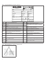 4
4
-
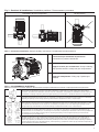 5
5
-
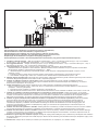 6
6
-
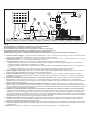 7
7
-
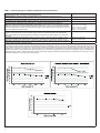 8
8
-
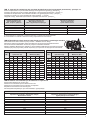 9
9
-
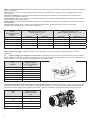 10
10
-
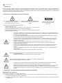 11
11
-
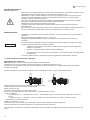 12
12
-
 13
13
-
 14
14
-
 15
15
-
 16
16
-
 17
17
-
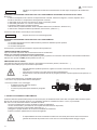 18
18
-
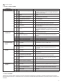 19
19
-
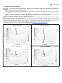 20
20
-
 21
21
-
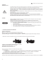 22
22
-
 23
23
-
 24
24
-
 25
25
-
 26
26
-
 27
27
-
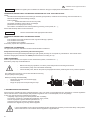 28
28
-
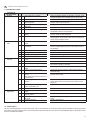 29
29
-
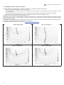 30
30
-
 31
31
-
 32
32
-
 33
33
-
 34
34
-
 35
35
-
 36
36
-
 37
37
-
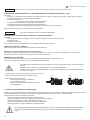 38
38
-
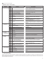 39
39
-
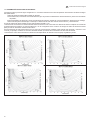 40
40
-
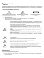 41
41
-
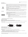 42
42
-
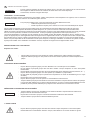 43
43
-
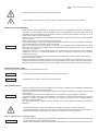 44
44
-
 45
45
-
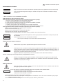 46
46
-
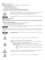 47
47
-
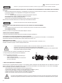 48
48
-
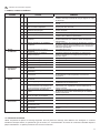 49
49
-
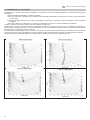 50
50
-
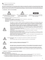 51
51
-
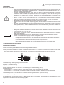 52
52
-
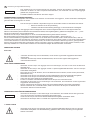 53
53
-
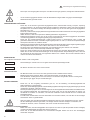 54
54
-
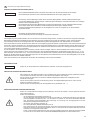 55
55
-
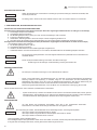 56
56
-
 57
57
-
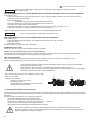 58
58
-
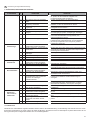 59
59
-
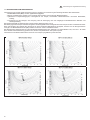 60
60
-
 61
61
-
 62
62
-
 63
63
-
 64
64
-
 65
65
-
 66
66
-
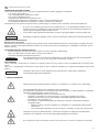 67
67
-
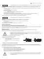 68
68
-
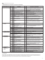 69
69
-
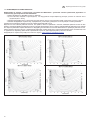 70
70
-
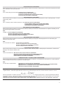 71
71
-
 72
72
-
 73
73
-
 74
74
-
 75
75
-
 76
76


Sulzer SKS End-Suction Centrifugal Pump Manual de usuario
- Tipo
- Manual de usuario
en otros idiomas
Artículos relacionados
Otros documentos
-
DAB CM-CP2 DN32 Manual de usuario
-
 Valex 1370636 El manual del propietario
-
-
SAER SAER CENTRIFUGAL 6BP4/110 Manual de usuario
-
SAER SAER CENTRIFUGAL FC 25-2C Manual de usuario
-
SAER SAER CM1 , 1.5 HP Manual de usuario
-
-
DAB KV A Series Instrucciones de operación
-
-
Comet MTP FW2 MISTING Manual de usuario
