KNOVA KN DP-2000 El manual del propietario
- Categoría
- Herramientas eléctricas
- Tipo
- El manual del propietario

KN DP-2000

Product specifications ......................................................... 1
Proposition 65 warning ........................................................ 1
.
Power tool safety ................................................................. 1
Drill press safety .................................................................. 2
Electrical requirements and safety ....................................... 3
Carton contents ................................................................... 4
Know your drill press ........................................................... 5
Glossary and adjustments ................................................. 6
Assembly and adjustments ................................................ 6
Operation ........................................................................... 10
Maintenance ...................................................................... 13
Troubleshooting guide ....................................................... 14
Parts list ............................................................................. 15
PRODUCT SPECIFICATIONS
POWER TOOL SAFETY:
1. READ and become familiar with the entire instruction man-
ual. LEARN the tool’s application, limitations and possible
hazards.
2. KEEP GUARDS IN PLACE and in work order.
3. DON’T USE IN DANGEROUS ENVIRONMENT. Don’t use
power tools in damp or wet locations, or expose them to rain.
Keep work area well lighted.
4. DO NOT use power tools in the presence of flammable
liquids or gases.
5. KEEP WORK AREA CLEAN. Cluttered areas and benches
invite accidents.
6. KEEP CHILDREN AWAY. All visitors should be kept a safe
distance from work area.
7. DON’T FORCE THE TOOL. It will do the job better and
safer at the rate for which it was designed.
8. USE THE RIGHT TOOL. Do not force tool or attachment to
do a job for which it was not designed.
9. WEAR PROPER APPAREL. Do not wear loose clothing,
gloves, neckties, rings, bracelets, or other jewellery, that may
get caught in moving parts. Non-slip footwear is recommend-
ed. Wear protective hair covering to contain long hair.
TABLE OF CONTENTS
1
PROPOSITION 65 WARNING
Some dust created by power sanding, sawing, grinding, drilling and other construction activities contains chemicals
(known to the State of California) to cause cancer, birth defects or other reproductive harm. Some examples of these
chemicals are:
•Lead based paints
•Crystalline silica from bricks, cement and other masonry products
•Arsenic and chromium from chemically treated lumber
Your risk from these exposures varies, depending on how often you do this type of work. To reduce your exposure to
these chemicals, work in a well-ventilated area and work with approved safety equipment, such as dust masks that are
specially designed to filter out microscopic particles.
Good safety practices are a combination of common sense, staying alert and understanding how to use your power
tool. To avoid mistakes that could cause serious injury, do not plug in your power tool until you have read and under-
stood the following safety rules:
Motor: 1/4 H.P. 120 V. 60 Hz.
Spindle taper: JT 33
Capacity: 1/2” (0 - 13 mm)
Speeds: (5) 800 - 3,450 R.P.M.
Chuck: 1/2” (13 mm)
Swing: 8” (203.2 mm)
Spindle travel: 2” (50.8 mm)
Overall height: 22-5/8” (574.6 mm)
Column diameter: 1-13/16” (46 mm)
Table size: 6-5/16” x 7-1/4” (160 x 158 mm)
Base size: 12-3/16” x 7-3/4” (310 x 196 mm)
Before using your drill press, it is critical that you read and understand these safety rules. Failure to follow these rules could
result in serious injury or damage to the drill press.

1. THE DRILL PRESS MUST BE BOLTED securely to a work-
bench. In addition, if there is any tendency for the drill press to
move during certain operations, bolt the workbench to the floor.
2. THIS DRILL PRESS is intended for use in dry conditions,
indoor use only.
3. WEAR EYE PROTECTION. USE face or dust mask along
with safety goggles if drilling operation is dusty. USE ear pro-
tectors, especially during extended periods of operation.
4. DO NOT wear gloves, neckties, or loose clothing.
5. DO NOT try to drill material too small to be securely held.
6. ALWAYS keep hands out of the path of a drill bit. Avoid awk-
ward hand positions where a sudden slip could cause your
hand to move into the drill bit.
7. DO NOT install or use any drill bit that exceeds 175 mm
(7”) in length or extends 150 mm (6”) below the chuck jaws.
They can suddenly bend outward or break.
8. DO NOT USE wire wheels, router bits, shaper cutters, cir-
cle (fly) cutters, or rotary planers on this drill press.
9. WHEN cutting a large piece of material make sure it is fully
supported at the table height.
10. DO NOT perform any operation freehand. ALWAYS hold
the workpiece firmly against the table so it will not rock or
twist. Use clamps or a vice for unstable workpiece.
11. MAKE SURE there are no nails or foreign objects in the
part of the workpiece to be drilled.
12. CLAMP WORKPIECE OR BRACE against the left side of
the column to prevent rotation. If it is too short or the table is
tilted, clamp solidly to the table.
13. IF THE WORKPIECE overhangs the table such that it will
fall or tip if not held, clamp it to the table or provide auxiliary
support.
14. SECURE WORK. Use clamps or vice to hold the work
when practical. It’s safer than using your hand and it frees
both hands to operate tool.
15. WHEN using a drill press vice, always fasten to the table.
16. MAKE SURE all clamps and locks are firmly tightened be-
fore drilling.
17. SECURELY LOCK the head and table support to the col-
umn, and the table to the table support before operating the
drill press.
18. NEVER turn your drill press ON before clearing the table
of all objects (tools, scraps of wood, etc.)
19. BEFORE STARTING the operation, jog the motor switch to
make sure the drill bit does not wobble or vibrate.
20. LET THE SPINDLE REACH FULL SPEED before starting
to drill. If your drill press makes an unfamiliar noise or if it
vibrates excessively, stop immediately, turn the drill press off
and unplug. Do not restart until the problem is corrected.
21. DO NOT perform lay out assembly or set up work on the
table while the drill press is in operation.
DRILL PRESS SAFETY
2
10. WEAR A FACE MASK OR DUST MASK. Drilling operation
produces dust.
11. DISCONNECT TOOLS before servicing; when changing
accessories such as blades, bits, cutters, and the like.
12. REDUCE THE RISK OF UNINTENTIONAL STARTING.
Make sure switch is in OFF position before plugging in.
13. USE RECOMMENDED ACCESSORIES. Consult the Op-
erator’s Manual for recommended accessories. The use of im-
proper accessories may cause serious injury.
14. REMOVE ADJUSTING KEYS AND WRENCHES. Form the
habit of checking to see that keys and adjusting wrenches are
removed from tool before turning it ON.
15. NEVER LEAVE TOOL RUNNING UNATTENDED. Turn pow-
er OFF. Don’t leave tool until it comes to a complete stop.
16. NEVER STAND ON TOOL. Serious injury could occur if
the tool is tipped or if the cutting tool is unintentionally con-
tacted.
17. DON’T OVERREACH. Keep proper footing and balance at
all times.
18. MAINTAIN TOOLS WITH CARE. Keep tools sharp and
clean for best and safest performance. Follow instructions for
lubricating and changing accessories.
19. CHECK FOR DAMAGED PARTS. Before further use of the
tool, a guard or other part that is damaged should be care-
fully checked to determine that it will operate properly and
perform its intended function – check for alignment of moving
parts, binding of moving parts, breakage of parts, mounting,
and any other conditions that may affect its operation. A guard
or other part that is damaged should be properly repaired or
replaced.
20. MAKE WORKSHOP CHILD PROOF with padlocks, mas-
ter switches, or by removing starter keys.
21. DO NOT operate the tool if you are under the influence of
any drugs, alcohol or medication that could affect your ability
to use the tool properly.
22. Dust generated from certain
material can be hazardous to your
health. Always operate the drill
press in a well-ventilated area and
provide for proper dust removal.
Use dust collection system
whenever possible.
23. ALWAYS WEAR EYE PROTECTION. Any drill press could
throw foreign objects into the eyes that could cause perma-
nent eye damage. ALWAYS wear Safety Goggles (not glass-
es) that comply with ANSI Safety standard Z87.1 Everyday
eyeglasses have only impact-resistant lenses. They ARE NOT
safety glasses.
NOTE: Glasses or goggles not in compliance with ANSI Z87.1
could cause serious injury.
POWER TOOL SAFETY:

22. USE RECOMMENDED SPEED for drill accessory and
workpiece material. SEE INSTRUCTIONS that come with the
accessory.
23. WHEN DRILLING large diameter holes, clamp the work-
piece firmly to the table. Otherwise, the bit may grab and spin
the workpiece at high speed. DO NOT USE fly cutters or mul-
tiple-part hole cutters, as they can come apart or become un-
balanced in use.
24. MAKE SURE the spindle has come to a complete stop
before touching the workpiece.
25. TO AVOID INJURY from accidental starting, always turn
the switch OFF and unplug the drill press before installing or
removing any accessory or attachment or making any adjust-
ment.
26. KEEP GUARDS IN PLACE and in working order.
27. USE ONLY SELF-EJECTING TYPE CHUCK KEY as pro-
vided with the drill press.
ELECTRICAL REQUIREMENTS AND SAFETY
3
IN THE EVENT OF A MALFUNCTION OR BREAKDOWN,
grounding provides a path of least resistance for electric cur-
rents and reduces the risk ofelectric shock. This tool is equipped
with an electrical cord that has an equipment-grounding con-
ductor and a grounding plug. The plug must be plugged into a
matching receptacle that is properly installed and grounded in
accordance with all local codes and ordinances.
DO NOT MODIFY THE PLUG PROVIDED. If it will not fit the
receptacle, have the proper receptacle installed by a qualified
electrician.
IMPROPER CONNECTION of the equipment grounding con-
ductor can result in risk of electric shock. The conductor with
the green insulation (with or without yellow stripes) is the
equipment grounding conductor. If repair or replacement of
the electrical cord or plug is necessary, DO NOT connect the
equipment grounding conductor to a live terminal.
CHECK with a qualified electrician or service person if you do
not completely understand the grounding instructions, or if you
are not certain the tool is properly grounded.
USE ONLY THREE-WIRE EXTENSION CORDS THAT HAVE
THREEPRONGED GROUNDING PLUGS WITH THREE-POLE
RECEPTACLES THAT ACCEPT THE TOOL’S PLUG. REPAIR OR
REPLACE DAMAGED OR WORN CORDS IMMEDIATELY.
GUIDELINES FOR EXTENSION CORDS
Make sure your extension cord is in good condition. Use an
extension cord heavy enough to carry the current your product
will draw. An undersized cord will cause a drop in line volt-
age resulting in loss of power, overheating and burning out of
the motor. The table on the right shows the correct size to use
depending on cord length and nameplate ampere rating. If in
doubt, use the next heavier gauge. The smaller the gauge num-
ber, the heavier the cord.
Be sure your extension cord is properly wired and in good
condition. Always replace a damaged extension cord or have
it repaired by a qualified person before using it. Protect exten-
sion cords from sharp objects, excessive heat and damp or wet
areas.
Use a separate electrical circuit for your tools. This circuit must
not be less than #12 wire and should be protected with a 15
Amp time lag fuse. Before connecting the motor to the power
line, make sure the switch is in the OFF position and electric
current is rated the same as the current stamped on the motor
nameplate. Running at a lower voltage will damage the motor.
This drill press is intended for use on a circuit that has a re-
ceptacle like the one illustrated below. This shows a 3-prong
electrical plug and receptacle that has a grounding conductor.
The Canadian Electrical Code prohibits the use of adapters.
Fig. 1 Three-Pronged Plug
Grounding Prong
Properly Grounded
Three-Pronged Receptacle
CAUTION In all cases, make certain the receptacle
is properly grounded. If you are not sure, have a
qualified electrician check the receptacle.
WARNING
This drill press is for indoor use only. Do not expose
to rain or use in damp locations.
DRILL PRESS SAFETY

CARTON CONTENTS
UNPACKING AND CHECKING CONTENTS
4
CAUTION
This drill must be grounded while in use to
protect the operator from electric shock.
Fig. 2
Grounding Lug
Adapter
Make sure this is
connected to a
known ground.
Two-Pronged
Receptacle
MINIMUM GAUGE FOR EXTENSION CORDS (AWG)
(When using 120 volts only)
Ampere Rating Total length of Cord
More Than Not More Than 25ft. 50ft. 100ft. 150ft.
0 6 18 16 16 14
6 10 18 16 14 12
10 12 16 16 14 12
12 16 14 12 Not Recommended
NOT SUPPLIED
•Adjustablewrench
•Hammerand
block of wood
•Combination
square
•Screwdrivers
ELECTRICAL REQUIREMENTS AND SAFETY
WARNING
If any part is missing or damaged, do not plug the drill press in until the missing or damaged
part is replaced, and assembly is complete.
Carefully unpack the drill press and all its parts, and compare against the list below.
To protect the drill press from moisture, a protective coating has been applied to the machined
surfaces. Remove this coating with a soft cloth moistened with a substance such as WD-40.
WARNING
To avoid fire or
toxic reaction,
never use gas-
oline, naphtha,
acetone, lac-
quer thinner or
similar highly
volatile sol-
vents to clean
the drill press.
TOOLS NEEDED FOR ASSEMBLY

Cover Stop nuts Depth
pointer ON/OFF
swich w/key
Motor Feed
spring
Depth scale
Feed stop rod
Spindle
Bevei lock
Base
Support lock
handle
5
CARTON CONTENTS
Base
Head/motor assembly
Table
Chuck key
Chuck
Support lock handle
Hex key (3 mm.)
Bolts (3)
Feed handles (3)
KNOW YOUR DRILL PRESS
Cover
Spindle pulley Motor pulley
Belt tension
knob
Chuck
Table
Column support
Table support
Column
Feed handle
Head lock
screws

GLOSSARY OF TERMS
6
BASE – Supports drill press. For additional stability, holes are
provided in base to bolt drill press to floor.
(See: SPECIFIC SAFETY INSTRUCTIONS FOR THE DRILL
PRESS.)
BACKUP MATERIAL – A piece of scrap wood placed between
the workpiece and table. The backup board prevents wood in
the workpiece from splintering when the drill passes through
the backside of the workpiece. It also prevents drilling into
the tabletop.
BELT TENSION – Refer to ASSEMBLY AND ADJUSTMENTS:
BELT TENSION, page12.
BELT TENSION LOCK KNOB – Tightening the knob locks the
motor bracket support maintaining correct belt distance and
tension.
BEVEL SCALE – Shows degree of table tilt for bevel opera-
tions. Scale is mounted on side of arm.
CHUCK – Holds drill bit or other recommended accessory to
perform desired operations.
CHUCK KEY – A self-ejecting chuck key that will pop out of
the chuck when you let go of it. This action is designed to help
prevent throwing of the chuck key from the chuck when the
power is turned ON. Do not use any other key as a substitute;
order a new one if damaged or lost.
COLUMN – Connects head, table, and base on a one-piece
tube for easy alignment and movement.
COLUMN SUPPORT – Supports column, and provides mount-
ing holes for column to base.
DEPTH SCALE – Indicates depth of hole being drilled.
DEPTH SCALE POINTER – Indicates the drilling depth by
pointing to the depth scale.
DEPTH SCALE LOCK – Locks the depth scale to selected
depth.
DRILL BIT – The cutting tool used in the drill press to make
holes in a workpiece.
DRILL ON/OFF SWITCH – Has locking feature. This feature
is intended to help prevent unauthorized and possible hazard-
ous use by children and others.
DRILLING SPEED – Changed by placing the belt in any of the
steps (grooves) in the pulleys. See Spindle Speed inside belt
guard.
FEED HANDLE – Moves the chuck up or down. One or two of
the handles may be removed if the workpiece is an unusual
shape and it interferes with the handles.
HEAD LOCKS – Locks the head to the column. ALWAYS lock
head in place while operating the drill press.
REVOLUTION PER MINUTE (R.P.M.) – The number of turns
completed by a spinning object in one minute.
SPINDLE SPEED – The R.P.M. of the spindle.
SPRING CAP – Adjusts quill spring tension.
SUPPORT LOCK – Tightening locks table support to column.
Always have it locked in place while operating the drill press.
TABLE – Provides working surface to support workpiece.
TABLE BEVEL LOCK – Locks the table in any position from
0° - 45°.
TABLE LOCK – Locks the table after it is rotated to various
positions.
TABLE SUPPORT – Rides on column to support table arm and
table.
WORKPIECE – Material being drilled.
ASSEMBLY AND ADJUSTMENTS
BASE/COLUMN (FIG. A)
1. Set the base (1) on the floor.
2. Place the column (2) on the base, aligning the holes in the
column support with the base holes.
3. Install a bolt (3) in each column support hole, and tighten
with an adjustable wrench.
TABLE (FIG. B)
1. Slide table assembly (1) down the column (2), until it rests
on the base.
2. Install the lock handle (3) in the threaded hole.
3. Slide the table up the column to working height and hand
tighten the lock handle to secure the table in place.
Fig. A Fig. B

ASSEMBLY AND ADJUSTMENTS
HEAD/MOTOR ASSEMBLY (FIG. C)
1. Lift above the column (2), slide down the column as far as
it will go.
2. Line the head up with the base.
3. Tighten the two locking screws (3) with the hex key
7
Fig. C
FEED ASSEMBLY (FIG. D)
1. Thread the feed handles (1) into the holes on the feed hub (2).
2. Hand tightens.
FEED ASSEMBLY (FIG. D)
1. Thread the feed handles (1) into the holes on the feed hub (2).
2. Hand tighten.
WARNING
Disconnect the drill press from the power source before
installing, adjusting, or removing the chuck.
CAUTION:
The head/motor assembly (1) is heavy. Lift carefully.
Fig. D
CHUCK (FIG. E, F)
1. Inspect and clean the hole in the chuck (1) and the spindle (2).
2. Remove all grease, coatings, and particles from the chuck
and spindle surfaces with a clean cloth moistened with a non-
oil based solution such as Rubbing Alcohol.
3. Open the chuck jaws (3), by turning the chuck barrel clock-
wise, and make sure the jaws are completely recessed inside
the chuck.
4. Seat the chuck (1) (Fig. F) onto the spindle by placing a
block of wood under the chuck, and tapping the wood with
a hammer, or tap the chuck with a rubber mallet or plastic-
tipped hammer.
5. Do not tap the chuck with a metal hammer.
MOUNTING THE DRILL PRESS (FIG. G)
The drill press must be securely fastened by the two base
holes to a stand or workbench with heavy-duty fasteners. This
will prevent the drill press from tipping over, sliding, or walk-
ing during operation.
IMPORTANT: If the stand or workbench has a tendency to
move during operation, fasten it securely to the floor.
Fig. E
1. Drill press base
2. Bolt
3. Flat washer
4. Rubber washer
5. Work surface
6. Flat washer
7. Lock washer
8. Hex nut
9. Jam nut
Fig. G

8
ASSEMBLY AND ADJUSTMENTS
SPINDLE SPEEDS (Fig. H)
This drill offers 5 spindle speeds from 800 to 3450 R.P.M.
The highest speed is obtained when the belt is positioned on
the largest motor pulley step and the smallest spindle pulley
step.
Fig. I
Fig. K
ALIGNING THE BELT PULLEYS (FIG. K)
Open the head cover of the Drill Press. Check alignment of
the pulleys with a straight edge (1) such as a framing square,
a level, or a piece of a wood. Lay the straight edge across the
top of the pulleys. If all three pulleys are NOT aligned:
1. Release belt pressure by loosening the belt tension lock
knobs (2) on either side of the head, counter clockwise.
2. Loosen the motor mount nuts (3). Lift or lower the motor (4)
until the pulleys are in line.
3. Tighten the motor mount nuts (3) using an adjustable wrench.
NOTE: To avoid rattles or other noise, the motor housing
should not touch the lower belt guard housing.
4. Retighten the belts by pulling the motor (4) toward the drill
press head, until the belt deflects approximately 1/2 inch
when pressed in the centre.
NOTE: Refer to the chart inside the belt guard cover for rec-
ommended drilling speeds and belt/pulley positions.
5. Lock the belt tension lock knobs (2) by turning clockwise.
NOTE: When the belts are new, it may be difficult to move the
belts. As the machine is used, the belts will gain more elastic-
ity and will be easier to adjust.
WARNING
Disconnect the drill press from the power source be-
fore making any adjustments.
Fig. H
TO MOVE THE TABLE (FIG. I)
1. Raise or lower the table (1) by loosening the support lock
handle (2).
2. Move the table to the desired position and tighten the sup-
port lock handle.
DRILL PRESS ADJUSTMENTS
CAUTION
All the adjustments for the operation of the drill press
have been completed at the factory. Due to normal
wear and use, some occasional readjustments may
be necessary.
WARNING
To avoid injury from an accidental start, ALWAYS make
sure the switch is in the OFF position, the switch key
is removed, and the plug is not connected to the pow-
er source outlet before making belt adjustment.
WARNING
To prevent personal injury, always disconnect the plug
from the power source when making any adjustment
SQUARING TABLE TO HEAD (FIG. L)
1. Insert a 3” drill bit (1) into the chuck (2), tighten by turning
the chuck barrel counter clockwise.
2. Place a combination square (4) on the table (3) as shown.
The drill bit should be parallel to the straight edge of the
square.
3. If an adjustment is needed, loosen the bevel lock (5) with
a wrench.
4. Square the table to the bit by tilting the table.
5. Tighten the bevel lock when square.
Motor
Spindle

ASSEMBLY AND ADJUSTMENTS
9
Fig. L
TO TILT THE TABLE SCALE (FIG. M)
NOTE: The table is not shown in Fig. M for clarity of illustration.
1. Loosen the bevel lock (1) with a wrench.
2. Tilt the table to the desired angle, using the bevel scale (2)
as a basic guide.
3. Tighten the bevel lock.
WARNING
Disconnect the drill press from the power source be-
fore making any adjustments.
2
1
Fig. M
SPINDLE / QUILL (FIG. N)
Rotate the feed handles counter clockwise to lower spindle
to its lowest position. Hand support the spindle securely and
move it back and forth around the axis. If there is too much
play, do the following:
1. Loosen the lock nut (1).
2. Turn the screw (2) clockwise to eliminate the play, but with-
out obstructing the upward movement of the spindle. (A little
play in the spindle is normal.)
3. Tighten the lock nut (1).
QUILL RETURN SPRING (FIG. O)
The quill return spring may need adjustment if the tension
causes the quill to return too rapidly or too slowly.
1. Lower the table for additional clearance.
2. Place a screwdriver in the lower front notch (1) of the spring
cap (2). Hold it in place while loosening and removing only the
outer jam nut (3).
3. With the screwdriver still engaged in the notch, loosen the
inner nut (4) just until the notch (5) disengages from the boss
(6) on the drill press head.
Fig. N
4. Carefully turn the spring cap (2) counter clockwise with the
screwdriver, engaging the next notch.
5. Lower the quill to the lowest position by rotating the feed
handle in a counter clockwise direction while holding the
spring cap (2) in position.
6. If the quill moves up and down as easily as you desire,
tighten the standard nut (4) with the adjustable wrench. If too
loose, repeat steps 2 through 5 to tighten. If too tight, reverse
steps 4 and 5.
DO NOT OVERTIGHTEN and restrict quill movement.
7. Place the jam nut (3) and tighten against the standard nut
(4) to prevent the standard nut from reversing.
CAUTION:
DO NOT REMOVE THIS INNER NUT, because the
spring will forcibly unwind.
Fig. O

ASSEMBLY AND ADJUSTMENTS
10
WARNING:
To avoid injury from an accidental start, ALWAYS
make sure the switch is in the OFF position, the
switch key is removed, and the plug is not connected
to the power source outlet before making belt adjust-
ment.
BELT TENSION (FIG. P)
Make sure pulleys are aligned properly as shown in Fig. K.
1. To unlock the belt tension, turn the belt tension lock knobs
(1) on each side of the drill press head counter clockwise.
2. Move the motor (2) toward the front of the drill press to
loosen the belt tension.
3. Position the belt on the correct pulley steps for the desired speed.
4. Pull the motor away from the drill press head until the belt
is properly tensioned.
NOTE: Belt tension is correct if the belt deflects approximate-
ly 1/2 inch when pressed at its centre.
5. Tighten the belt tension lock knobs (1) on each side of the
drill press head.
OPERATION
Fig. P
BASIC DRILL PRESS OPERATIONS
SPEEDS AND BELT PLACEMENT (FIG. Q)
This drill press has 5 speeds, as listed below:
800 RPM 1260 RPM 1800 RPM
2400 RPM 3450 RPM
See inside of the pulley guard for specific placement of the
belts on the pulleys to change speeds.
WARNING:
To avoid possible injury, keep guard closed, in place,
and in proper working order while tool is in opera-
tion.
Fig. Q
Belt / pulley position-RPM chart
BELT. A-1 BELT. B-2 BELT. C-3
BELT. D-4 BELT. E-5
ON/OFF SWITCH PANEL (FIG. R)
The ON / OFF switch has a removable, yellow plastic key.
With the key removed from the switch, unauthorized and haz-
ardous use by children and others is minimized.
1. To turn the drill press ON, insert yellow key (1) into the slot
(2) in the centre of the switch.
2. Push the key firmly into the slot, and then push switch to
the ON position to start the drill press.
3. To turn the drill press OFF, push the switch to the down
position.
4. Remove the yellow switch key, when the saw has come to
a complete stop, by gently pulling it outward.
WARNING:
ALWAYS lock the switch OFF when the drill press
is not in use. Remove the key and keep it in a safe
place. In the event of a power failure, blown fuse, or
tripped circuit breaker, turn the switch OFF and re-
move the key, preventing an accidental start-up when
power comes on.
Fig. R

OPERATION
11
Make sure that the drill is centred in INSTALLING DRILL BIT
IN CHUCK (FIG. S)
1. With the switch OFF and the yellow switch key removed,
open the chuck jaws (1) using the chuck key (2). Turn the
chuck key counter clockwise to open the chuck jaws (1).
2. Insert the drill bit into the chuck far enough to obtain maxi-
mum gripping by the jaws, but not far enough to touch the
spiral grooves (flutes) of the drill bit when the jaws are tight-
ened.
3. Make sure that the drill is centred in the chuck.
4. Turn the chuck key clockwise to tighten the jaws.
WARNING:
To avoid injury or accident by the chuck key eject-
ing forcibly from the chuck when the power is turned
ON, use only the self-ejecting chuck key supplied
with this drill press. ALWAYS recheck and remove the
chuck key before turning the power ON.
Fig. S
DRILLING TO A SPECIFIC DEPTH
Drilling a blind hole (not all the way through workpiece) to a
given depth can be done two ways:
Workpiece method (Fig. U and V)
1. Mark the depth (1) of the hole on the side of the workpiece.
2. With the switch OFF, bring the drill bit (2) down until the tip
is even with the mark.
3. Hold the feed handle at this position.
4. Spin the lower nut (3) down to contact the depth stop lug
(6) on the head.
5. Spin the upper nut (5) down and tighten against the lower
nut (3).
6. The drill bit will now stop after travelling the distance
marked on the workpiece.
Depth scale method (Fig. V)
Note: With the chuck up, the tip of the drill bit must be just
slightly above the top of the workpiece.
1. With the switch OFF, turn the feed handle until the pointer
(7) points to the desired depth on the depth scale (4) and hold
the feed handle in that position.
2. Spin the lower nut (3) down to contact the depth stop lug (6).
3. Spin the upper nut (5) against the lower stop nut and tighten.
4. The drill bit will stop after travelling the distance selected
on the depth scale.
Fig. V

a OPERATION
12
REMOVING CHUCK (FIG. W)
1. With the switch OFF, open the jaws of the chuck as wide as
possible by turning the chuck counter clockwise.
2. Tap the chuck (1) lightly with a plastic tipped hammer at the
top of chuck, until the chuck releases.
NOTE: Place one hand below the chuck to catch it when it
falls out.
WARNING:
To avoid injury from an accidental start, ALWAYS
make sure the switch is in the OFF position, the
switch key is removed, and the plug is not connected
to the power source outlet before removing or install-
ing the chuck.
BASIC OPERATION INSTRUCTIONS
To get the best results and minimize the likelihood of personal
injury, follow these instructions for operating the drill press.
WARNING:
For your own safety, always observe the SAFETY IN-
STRUCTIONS listed here and on pages 3, 4 and 5 of
the Operator’s Manual.
WARNING:
To avoid being pulled into the power tool, do not wear
loose clothing, gloves, neckties, or jewellery. Always
tie back long hair.
Fig. W
YOUR PROTECTION
1. If any part of your drill press is missing, malfunctioning,
damaged or broken, stop operation immediately until that part
is properly repaired or replaced.
2. Never place your fingers in a position where they could
contact the drill bit or other cutting tool. The workpiece may
unexpectedly shift, or your hand could slip.
3. Avoid injury from parts being thrown by the spring tension
of the quill.
4. To prevent the workpiece from being torn from your hands,
thrown, spun by the tool, or shattered, always properly sup-
port your workpiece as follows:
a. Always position backup material (used beneath work-
piece) so that it contacts the left side of the column, and a
clamp to brace a small workpiece.
b. Whenever possible, position the workpiece to contact
the left side of the column. If it is too short or the table is
tilted, or clamp solidly to the table, using the table slots.
c. When using a drill press vice, always fasten it to the
table.
d. Never do any work freehand (hand-holding the work-
piece rather than supporting it on the table).
e. Securely lock the head and support to the column, the
table arm to the support, and the table to the table arm,
before operating the drill press.
f. Never move the head or the table while the tool is run-
ning.
g. Before starting an operation, jog the motor switch to
make sure the drill or other cutting tool does not wobble
or cause vibration.
h. If a workpiece overhangs the table so it will fall or tip
if not held, clamp it to the table or provide auxiliary sup-
port.
i. Use fixtures for unusual operations to adequately hold,
guide, and position workpiece.
j. Use the spindle speed recommended for the specific
operation and workpiece material. Check the panel on the
inside pulley cover or the chart below for drilling speed
information. For accessories, refer to the instructions pro-
vided with each accessory.
5. Never stand on the drill press table, it could break or pull
the entire drill press down on you.
6. Turn the motor switch OFF, and put away the switch key
when leaving the drill press.
7. To avoid injury from thrown work or tool contact, do not
perform layout, assembly, or set up work on the table while
the cutting tool is rotating.
DRILLING SPEED TABLE (rpm)
Drill Bit
Dia.
(Inches) Wood Alum., Zinc, Brass Iron, Steel
Material
3450
1800
1/16
1/8
3/16
1/4
5/16
3/8
1/2
3450
2400
1800
1260
800
3450
2400
1800
1260

OPERATION
13
POSITIONING THE TABLE AND WORKPIECE (FIG. X and Y)
1. Lock the table (1) to the column (2) at a position so the tip of
the drill bit (3) is just above the top of the workpiece (4).
2. ALWAYS place backup material (scrap wood) on the table
beneath the workpiece. This will prevent splintering or heavy
burring on the underside of the workpiece. To keep the back-
up material from spinning out of control, it MUST contact the
LEFT side of the column.
3. For a small piece that cannot be clamped to the table, use
a drill press vice (optional accessory).
WARNING:
To prevent the workpiece or backup material from be-
ing torn from your hands while drilling, you MUST
position the workpiece against the LEFT side of the
column. If the workpiece or the backup material is not
long enough to reach the column, clamp them to the
table, to brace the workpiece. Failure to secure the
workpiece could result in personal injury.
Fig. X
WARNING:
The drill press vice MUST be clamped or bolted to the
table to avoid injury from a spinning workpiece, dam-
aged vice or bit parts
HOLDING A DRILLING LOCATION
1. Using a centrepunch or sharp nail, make an indentation in
the workpiece where you want the hole.
2. Using the feed handles, bring the drill down to align with
the indentation before turning the drill ON.
Fig. Y
MAINTENANCE
Frequently use an air compressor or vacuum to clear out ac-
cumulated dust in the motor.
A coat of automotive paste wax applied to the table and col-
umn will help to keep the surface clean
WARNING:
For your own safety, turn the switch OFF and remove
the plug from the power source outlet before main-
taining or lubricating the drill press.
WARNING:
To avoid shock or fire hazard, if the power cord is worn
or cut in any way, have it replaced immediately.
LUBRICATION
All of the drill press ball bearings are packed with grease at
the factory. They require no further lubrication.
Periodically, lubricate the elevation mechanism (rack and pin-
ion) and the teeth of the quill.

14
TROUBLESHOOTING GUIDE
REMEDY
1. Adjust tension. See
ASSEMBLY-TENSIONING BELT.
2. Lubricate spindle. See LUBRICATION.
3. Check tightness of retaining nut on
pulley, and tighten if necessary.
4. Tighten set screw in motor pulley.
1. Change speed. See BASIC DRILL
PRESS OPERATION- SPINDLE SPEEDS.
2. Retract drill frequently to clear chips.
3. Resharpen drill bit.
4. Feed fast enough – allow drill to cut.
5. Lubricate drill. See BASIC
DRILL PRESS OPERATION-FEEDING.
1. Resharpen drill bit correctly.
2. Replace drill bit.
1. Use backup material. See BASIC
DRILL PRESS OPERATION.
1. Support workpiece or clamp it. See
BASIC DRILL PRESS OPERATION.
1. Support workpiece or clamp it.
See BASIC DRILL PRESS OPERATION.
2. Adjust tension. See
ASSEMBLY– TENSIONING BELT.
1. Use a straight drill bit.
2. Replace bearings.
3. Install drill properly. See BASIC DRILL
PRESS OPERATION and ASSEMBLY.
4. Install chuck properly. See
ASSEMBLY – INSTALLING THE CHUCK.
1. Adjust spring tension. See ASSEMBLY AND
ADJUSTMENTS –QUILL RETURN SPRING.
1. Using a household detergent or non-oil
based cleaning solution such as Rubbing
Alcohol, clean the tapered surface of the
chuck and spindle to remove all dirt, grease
and oil. See ASSEMBLY – INSTALLING THE
CHUCK.
PROBLEM
Noisy operation
Drill bit burn.
Runout of drill bit point,
drilled hole not round.
Wood splinters on
underside.
Workpiece torn loose
from hand.
Drill bit binds in workpiece.
Excessive drill bit runout
or wobble.
Quill returns too slow
or too fast.
Chuck will not stay attached
to spindle. It falls off when
trying to install.
WARNING
To avoid injury from an accidental start, turn the switch OFF and always remove the plug from the power source before
making any adjustment.
•ConsultyourlocalcallServiceCentreifforanyreasonthemotorwillnotrun.
POSSIBLE CAUSES
1. Incorrect belt tension.
2. Dry spindle.
3. Loose spindle pulley.
4. Loose motor pulley.
1. Incorrect speed.
2. Chip not coming out of hole.
3. Dull drill bit.
4. Feeding too slowly.
5. Not lubricated.
1. Hand grain in wood or lengths
of cutting flutes and/or angles
not equal.
2. Bent drill bit.
1. No backup material under
workpiece.
1. Not supported or clamped
properly.
1. Workpiece pinching drill bit,
or excessive feed pressure.
2. Improper belt tension.
1. Bent drill bit.
2. Worn bearings.
3. Drill bit not properly installed
in chuck.
4. Chuck not properly installed.
1. Spring has improper tension.
1. Dirt, grease, or oil on the tapered
inside surface of chuck or on
the spindle’s tapered surface.

15
PARTS LIST
1
1
1
3
1
1
1
1
1
2
1
1
1
10
1
1
1
3
1
1
1
2
1
3
1
2
1
1
1
1
1
2
1
1
1
Description Qty
Part No.
C-ring
Driving sleeve
Ball bearing
Collar
Spindle pulley
Chuck
Motor ass´y
Motor pulley
Hex. soc. set screw
Strain relief
Power cable
Rocker switch
Switch cover
Cr. re.pan hd screw
Pulley cover ass´y
Cr. re. round washer hd. screw
V-Belt
Flat washer
Chuck key holder
Cr. re.round washer hd. screw
Chuck key
Spring pin
Manual
Carton
Label
Warning label
Label
Speed label
Sticker
Label
Hex. nut
Cr. re. pan hd. screw
External tooth lock washer
Lock nut
Hex wrench
1
1
2
1
1
1
1
1
2
2
1
1
1
4
1
4
1
4
1
1
1
1
1
1
1
1
1
1
1
1
1
2
2
2
1
Base
Column holder
Body column
Hex. hd. bolt
Table bracket
Cr. re. pan hd. screw
Hex. nut
Set ring
Set bolt
Hex nut
Pointer
Hex. hd. bolt
Tilting scale
Drive screw
Table lock handle
Table
Head
Hex. soc. set screw
Spring
Motor rod
Shifter bolt
Hex. hd. screw and washer
Feed shaft
Handle bar ass´y
Spring cap ass´y
Hex. nut
Quill set screw
Hex. nut
Quill
Rubber washer
Spindle
Ball bearing
C-ring
C-ring
Terminal
0VH4
0VH7
0VH8
0JQ7
0VH9
0KDM
0KNE
0VHJ
047U
0KNJ
047Y
0JTA
0481
0K9X
05VC
0VHA
0VHB
0JXE
04WG
048K
05X6
0K1S
048Q
048Z
0VHC
0KPU
049C
0KNL
0VHG
04XH
0WPC
0HVV
0JE9
0JEE
0KUX
0VHM
0VHL
0HVX
04XU
0VHN
0WPK
120X
0VHS
0JX9
0KSB
0L5Y
0LWC
04AF
0KFG
0W2P
0K7Q
0JJR
0J8F
05SZ
0K7K
0VHY
0JCB
2ZLC
0WHB
0WYP
04PM
04Q4
2ZLA
0KND
0KFF
0JAF
0KR4
0J3P
10200131
10200202
10200407
2601BBDA90
10200603
2668BBDA27
2701FZD106
10200907
10201004
2701FZD111
10201202
2601QBDS81
10201602
2658MZDU36
106020001
10202104
10202514
2603BBLA52
10303101
10203215
10604201
2615BZDD28
10203804
10204306A5
10205001A1
2701QZD609
10205405
2701FZD113
10205603
10305701
10205808
2001ZZ6201
2570BBN111
2570BBN117
2805U5HN16
Key No.
M5*0.8-20
M6*1.0 T=5
M10*1.5
M10*1.5 T=4
ø2.3-5
M8*1.25-8
M8*1.25-25
3/8*24UNF T=8
M8*1.25 T=6.5
ø40 , T=2mm
Description Qty
Part No.Key No.
M6*1.0-10
M5*0.8-12 Zinc
M6*1.0-12
M5*0.8 T=4
M5*0.8-8
ø5
M8*1.25 T=8
2570BBN122
10206522
2001ZZ6203
10306701
10207025
2135CTQ142
8015B20204A1
10207906
2603BBLA38
2801ABHA03
2807BB02H2
2898D08G24
10208813
2668BZDA24
0209005A1
2641BZDA39
2572ARK260
2501NNVN11
10511201
2641BBDA39
2136BBD506
2536MBE606
10022ZLC
10216280
82041272
10216520
10216715
10022ZLA
2701FZD105
2668BZDA23
2504MZC005
2705FZD108
2138MBL704
SizeSize

EXPLODED VIEW
16

17
TABLA DE CONTENIDOS
Especificaciones de producto ........................................... 17
Advertencia ....................................................................... 17
Seguridad de las herramientas eléctricas ......................... 17
Seguridad del taladro de prensa ....................................... 18
Requerimientos eléctricos y seguridad ............................. 19
Contenido de la caja ......................................................... 20
Conozca su taladro de prensa .......................................... 21
Glosario ............................................................................. 22
Ensamblado y ajustes ........................................................ 22
Operación .......................................................................... 26
Mantenimiento .................................................................. 29
Guía de resolución de problemas ..................................... 30
Lista de partes ................................................................... 31
Diagrama de ensamblado .................................................. 32
ESPECIFICACIONES DEL PRODUCTO
SEGURIDAD DE LAS HERRAMIENTAS ELÉCTRICAS
1. LEA y familiarícese con todo el manual de instrucciones.
APRENDA las aplicaciones de la herramienta, limitaciones y
posibles riesgos.
2. MANTENGA LAS PROTECCIONES EN SU LUGAR y en or-
den de trabajo.
3. NO USE EN AMBIENTES PELIGROSOS. No utilice her-
ramientas eléctricas en lugares húmedos o mojados, o los
exponga a la lluvia. Mantenga el área de trabajo bien ilumi-
nada.
4. NO utilice herramientas eléctricas en presencia de líquidos
inflamables o de gases.
5. MANTENGA EL ÁREA DE TRABAJO LIMPIA. Aéreas y ban-
cos obstruidos ocasionan accidentes.
6. MANTENGA A LOS NIÑOS ALEJADOS. Todos los visitan-
tes deben mantener una distancia segura del área de trabajo.
7. NO FORCE LA HERRAMIENTA. Realizará mejor el trabajo y
de manera más segura en el ritmo para el que fue diseñada.
8. UTILICE LA HERRAMIENTA ADECUADA. No fuerce la her-
ramienta o el accesorio para realizar un trabajo para el cual
no fueron diseñados.
9. UTILICE VESTIMENTA APROPIADA. No utilice ropas
¡ADVERTENCIA!
Algunos polvos generados por el lijado eléctrico, el corte, el molido, el taladrado y otras actividades de la construcción
contienen químicos que pueden causar cáncer, defectos congénitos y otros daños reproductivos. Algunos ejemplos de
estos químicos son:
• Pinturas a base de plomo
• Dióxido de silicio de ladrillos, cemento y otros productos de albañilería.
• Arsénico y cromo de madera tratada químicamente.
El riego proveniente de la exposición varía dependiendo de cuán seguido usted realice este tipo de trabajo. Para reducir
su exposición a estos químicos: trabaje en un área bien ventilada y con equipo de seguridad aprobado tal como más-
caras de polvo que están especialmente diseñadas para filtrar partículas microscópicas.
Las buenas prácticas de seguridad son una combinación de sentido común, permanecer alerta y comprender cómo
utilizar su herramienta eléctrica. Para evitar errores que puedan causar heridas graves, no enchufe su herramienta
eléctrica hasta haber leído y comprendido las siguientes reglas de seguridad:
Motor: 1/4 H.P. 120 V. 60 Hz.
Cono morse: JT 33
Capacidad: 1/2” (0 - 13 mm)
Velocidades: (5) 800 - 3,450 R.P.M.
Broquero: 1/2” (13 mm)
Giro: 8” (203.2 mm)
Carrera de husillo: 2” (50.8 mm)
Altura total: 22-5/8” (574.6 mm)
Diametro de columna: 1-13/16” (46 mm)
Mesa de trabajo: 6-5/16” x 7-1/4” (160 x 158 mm)
Base: 12-3/16” x 7-3/4” (310 x 196 mm)
Antes de utilizar su Taladro de Prensa, es muy importante que usted lea y comprenda estas reglas de seguridad. Si no se
respetaran estas reglas usted podría sufrir accidentes o dañar el taladro de Prensa.

SEGURIDAD DE LAS HERRAMIENTAS ELÉCTRICAS
18
sueltas, guantes, corbatas, anillos, pulseras, u otras alhajas
que puedan ser atrapadas por partes móviles. Se recomienda
calzado que no sea resbaladizo. Utilice protección del cabello
para contener cabello largo.
10. UTILICE UNA MÁSCARA FACIAL O MÁSCARA DE POL-
VO. La operación del taladro produce polvo.
11. DESCONECTE LAS HERRAMIENTAS Antes de hacerles
mantenimiento; cuando cambie accesorios tales como cuchil-
las, mechas, cortadores etcétera.
12. REDUZCA EL RIESGO DE COMIENZO ACCIDENTAL.
Asegúrese de que el interruptor esté en la posición OFF an-
tes de enchufar.
14. REMUEVA PIEZAS DE AJUSTE Y LLAVES. Hágase el
hábito de verificar que las llaves y piezas de ajuste sean re-
movidos de la herramienta antes de prenderla.
15. NUNCA DEJE LA HERRAMIENTA EN MARCHA SIN SU-
PERVISIÓN. APAGUELA. No deje la herramienta hasta que se
detenga totalmente.
16. NUNCA SE PARE SOBRE LA HERRAMIENTA. Graves he-
ridas pueden ocurrir si se inclina la herramienta o si las her-
ramientas de cortado son tocadas accidentalmente.
17. NO SE EXTRALIMITE. Mantenga un buen apoyo en los
pies y balance en todo momento.
18. MANTENGA LAS HERRAMIENTAS CON CUIDADO. Man-
tenga las herramientas afiladas limpias para obtener la mejor
y más segura prestación. Siga las instrucciones para lubricar
y cambiar accesorios.
19. REVISE SI HAY PARTES DAÑADAS. Antes de seguir uti-
lizando la herramienta, una protección u otra parte dañada
debe ser cuidadosamente examinada para determinar si op-
erará de manera correcta y si realizará sus funciones deter-
minadas. Verifique la alineación de partes móviles, uniones
de partes móviles, rotura de partes, montajes y cualquier otra
condición que pueda afectar su operación. Una protección o
cualquier otra parte dañada debe ser debidamente reparada
o reemplazada.
20. HAGA SU TALLER A PRUEBA DE NIÑOS con candados,
interruptores maestros o removiendo llaves de encendido.
21. NO opere la herramienta si está bajo la influencia de cu-
alquier tipo de droga, alcohol o medicación que pueda afectar
su capacidad de utilizar la herramienta de manera debida.
22. El polvo generado por ciertos materiales puede ser peli-
groso para su salud. Siempre opere el taladro de Prensa en
un área bien ventilada y asegúrese de una correcta remoción
del polvo. Utilice sistemas de recolección de polvo cuando
sea posible.
23. SIEMPRE UTILICE
PROTECCIÓN OCULAR. Todo
taladro de Prensa puede arrojar
objetos extraños a los ojos que
pueden causar daños
permanentes. SIEMPRE utilice
gafas de seguridad
(no anteojos) que cumplan con los estándares de seguridad
ANSI Z87.1 los anteojos comunes sólo tienen lentes que re-
sisten impactos. NO SON Gafas de seguridad.
NOTA: Las Gafas que no cumplan con ANSI Z87.1 pueden
causar heridas graves.
1. EL TALADRO DE PRENSA DEBE ESTAR ATORNILLADO de
manera segura al banco de trabajo. Además, si hubiera una
tendencia del taladro a moverse durante ciertas operaciones,
atornille el banco de trabajo al suelo.
2. ESTE BANCO DE TRABAJO es para utilizar en condiciones
secas y de interior únicamente.
3. UTILICE PROTECCIÓN OCULAR. UTILICE máscaras de
polvo o faciales junto con gafas de seguridad si la operación
de taladrado genera polvo. UTILICE protectores debidos es-
pecialmente durante largos períodos de operación.
4. NO utilice guantes, corbatas o ropas sueltas.
5. NO intente taladrar materiales demasiado pequeños como
para ser sujetados de manera segura.
6. SIEMPRE mantenga sus manos fuera de la trayectoria de la
broca. Evite posiciones de manos extrañas donde un resbalón
imprevisto puede causar que su mano se desplace hacia la
broca.
7. NO instale o utilice ninguna broca que exceda 175 mm (7”)
de largo o se extienda 150 mm (6”) por debajo de los dientes
del mandril. Pueden doblarse imprevistamente o romperse.
SEGURIDAD DEL TALADRO DE PRENSA
8. NO UTILICE carreteles de cable, brocas de fresado, tornos,
cortadores circulares o pulidoras en este Taladro de Prensa.
9. CUANDO corte una pieza grande de material asegúrese de
que esté debidamente ajustada a la altura de la mesa.
10. NO realice ninguna operación sin manos. Siempre sos-
tenga la pieza firmemente contra la mesa para que no se
balancee o tuerza. Utilice pinzas o sargentos para piezas in-
estables.
11. ASEGÚRESE de que no haya clavos u objetos extraños en
la pieza a ser taladrada.
12. ASEGURE LA PIEZA contra el lado izquierdo de la co-
lumna para prevenir una rotación. Si es demasiado corta o la
mesa está inclinada, asegúrela firmemente contra la mesa.
13. SI LA PIEZA sobresale de la mesa de manera tal que pu-
eda caerse o volcarse si no se sujeta, asegúrela a la mesa o
provea un apoyo auxiliar.
14. TRABAJO SEGURO. Utilice pinzas o abrazaderas para
ajustar el trabajo cuando sea práctico. Es más seguro que
utilizar sus manos y las libera para operar la herramienta.

SEGURIDAD DEL TALADRO DE PRENSA
19
15. CUANDO utilice una prensa de taladrado, siempre
asegúrela a la mesa.
16. ASEGÚRESE de que todas la pinzas y seguros estén firme-
mente ajustados antes de taladrar.
17. TRABE FIRMEMENTE el cabezal y el apoyo de la mesa a
la columna, y la columna a la mesa de apoyo antes de operar
el Taladro de Prensa.
18. NUNCA encienda su taladro antes que limpiar la mesa de
todos los objetos (herramientas, restos de madera, etc.)
19. ANTES DE COMENZAR la operación, mueva lentamente
el interruptor del motor para asegurarse de que la broca del
taladro no se tambalee o vibre.
20. PERMITE QUE EL EJE ALCANCE LA VELOCIDAD MÁX-
IMA antes de comenzar el taladrado. Si su Taladro de Prensa
realiza un sonido extraño o si vibra excesivamente, detenga
inmediatamente, apague el taladro y desconecte. No reinicie
hasta que el problema sea corregido.
21. NO realice procedimientos de preparación o presente
trabajo sobre la mesa mientras el taladro se encuentra en op-
eración.
22. UTILICE LA VELOCIDAD RECOMENDADA para los ac-
cesorios de taladrado y material de trabajo. VEA LAS IN-
STRUCCIONES que vienen con el accesorio.
23. CUANDO TALADRE agujeros de gran diámetro, asegure
la pieza de trabajo firmemente a la mesa. Si no lo hiciera, la
broca podría hacer girar la pieza de trabajo a gran velocidad.
NO UTILICE cortadores voladizos o cortadores de agujeros
de múltiples partes, dado que pueden desarmarse o volverse
inestables en el uso.
24. ASEGÚRESE de que el eje haya llegado a una completa
detención antes de tocar la pieza.
25. PARA EVITAR HERIDAS producidas por inicios accidental-
es, siempre apague y desconecte el taladro antes de instalar
o remover cualquier accesorio o de hacer cualquier ajuste.
26. MANTENGA LAS PROTECCIONES EN SU LUGAR y en
orden de trabajo.
27. UTILICE UNICAMENTE LA PINZA DEL MANDRIL AUTO
EXTRAIBLE. Tal como es provista con el Taladro de Prensa.
REQUERIMIENTOS ELÉCTRICOS Y SEGURIDAD
EN EL CASO DE UN DESPERFECTO O ROTURA, la descarga
a tierra provee un camino de menor resistencia a la corriente
eléctrica y reduce el riesgo de electrocución. Esta herramien-
ta está equipada con un cable de electricidad que tiene el
conductor a tierra del equipo y un enchufe con conexión a
tierra. La calvija DEBE ser conectada en un toma corriente
debidamente instalado y con conexión a tierra de acuerdo con
TODAS las regulaciones y leyes locales.
NO MODIFIQUE EN LA CLAVIJA PROVISTA. Si no encaja en
el toma corriente, haga que un electricista calificado instale el
toma corriente adecuado.
LA CONEXIÓN INDEBIDA del conductor a tierra del equipo
puede resultar en riesgo de electrocución. El conductor con
recubrimiento aislante verde (o con rallas amarillas) es el con-
ductor de tierra del equipo. Si repara o reemplaza el cable
eléctrico o la clavija, NO conecte el conductor a tierra del
equipo a una terminal viva.
VERIFIQUE con un electricista calificado o personal de ser-
vicio si no comprende las instrucciones de descarga a tierra
completamente, o si no está seguro de que la herramienta
tenga su debida descarga a tierra.
UTILICE ÚNICAMENTE CABLES DE EXTENSIÓN DE TRES
PIEZAS QUE TENGAN 3 PUNTAS CON DESCARGA A TIER-
RA Y TOMACORRIENTES DE TRES POLOS QUE ACEPTEN
EL ENCHUFE DE LA HERRAMIENTA. REPARE O REEMPLACE
CABLES DESGASTADOS O DAÑADOS INMEDIATAMENTE.
GUÍA PARA CABLES DE EXTENSIÓN
Asegúrese de que su cable de extensión se encuentre en
buenas condiciones. Cuándo utilice un cable de extensión,
asegúrese de utilizar uno lo suficientemente resistente como
para conducir la electricidad que su producto requerirá. Un
cable más pequeño que el necesario puede causar una baja
en la tensión resultando una pérdida de potencia y un reca-
lentamiento. La tabla a continuación muestra el tamaño cor-
recto para utilizar de acuerdo a la distancia del cable y el
rótulo de la medida de amperaje. Si está en duda, utilice el
calibre superior siguiente. Cuanto más pequeño el número
del calibre, más pesado el cable.
Asegúrese de que su cable de extensión esté correctamente
cableado y en buenas condiciones. Reemplace siempre un
cable de extensión dañado o hágalo reparar por una perso-
na calificada ante utilizarlo. Proteja los cables de extensión
de objetos cortantes, calor excesivo y áreas húmedas o mo-
jadas.
Utilice circuitos eléctricos separados para sus herramientas.
Éste circuito debe tener un cable no inferior al #12 y debe
estar protegido por un fusible temporal de 15 A.
Antes de conectar el motor a la línea de electricidad, asegúrese
de que el interruptor se encuentre en la posición OFF y de que
la corriente corresponde con la que se encuentra estampada
en el rótulo del motor. La utilización bajo un voltaje inferior
puede dañar al motor. El taladro está diseñado para ser uti-
lizado en un circuito que tiene un toma corriente como el que
se muestra a continuación. Éste muestra un enchufe eléctrico
de tres puntas en toma corriente que posee un conductor con
descarga a tierra.
El código eléctrico de Canadá prohíbe el uso de adaptadores
PRECAUCIÓN:
En todos los casos, asegúrese de que el toma cor-
riente en cuestión esté debidamente conectado a
tierra. Si no está seguro, haga que un electricista
certificado verifique el toma corriente.

NO INCLUIDO
•Llaveajustable
•Martilloybloque
de madera
•Escuadra
•Destornillador
HERRAMIENTAS NECESARIAS PARA EL ENSAMBLAJE
20
REQUERIMIENTOS ELÉCTRICOS Y SEGURIDAD
CUIDADO:
El Taladro de Prensa es únicamente para uso en in-
teriores. No lo exponga a la lluvia o utilice en lugares
húmedos.
Fig. 1 Clavija triple
Tierra
Contacto adecuado
para la clavija triple
Fig. 2 Espiga de tierra
Adaptador
A segúrese
que esté
conectado
a tierra
Contacto
para
clavija
doble
CUIDADO:
Este Taladro de Prensa debe estar conectado a tierra mientras se
encuentra en uso para proteger al operador de electrocución.
MAGNITUD MÍNIMA PARA CABLES DE EXTENSIÓN (AWG)
(Únicamente cuando se utilizan 120 V)
Amperes graduación Distancia total del cable en m.
Más de No más de 7,65 15,24 30,48 45,72
0 6 5,48 4,87 4,87 4,87
6 10 5,48 4,87 4,26 3,65
10 12 4,87 4,87 4,26 3,65
12 16 4,26 3,65 No recomendable
CONTENIDO DE LA CAJA
DESEMPACADO Y VERIFICACIÓN DE CONTENIDOS
CUIDADO
Si alguna parte no se encontrara o estuvieran dañadas, no conecte el Taladro de Prensa
hasta que la parte extraviada o dañada sea reemplazada, y el ensamblaje se complete.
Desempaque cuidadosamente el Taladro de Prensa y todas sus partes y compare con
la lista a continuación.
Para proteger el Taladro de Prensa de la humedad, un recubrimiento protector a sido
aplicado en las superficies de la máquina. Remueva esta protección con un paño suave
humedecido con una sustancia como WD-40.
CUIDADO
Para evitar fuego o
reacciones tóxicas,
nunca utilice gaso-
lina, nafta, acetona,
thinner o solventes
igualmente volátiles
para limpiar el Tal-
adro de Prensa.

Cubierta Freno de
altura Indicador de
profundidad
ON/OFF
encendedor
con llave
Motor
resorte de
alimentación
Escala de
profundidad
Barra de freno
de alimentación
Huso
Seguro de inclinación
Base
ensamble del cabezal/de motor
Mesa
Llave de
broquero
Broquero
Manija de cerradura
Llave allen (3
Cerrojos (3)
Majas de alimentación (3)
CONOZCA SU TALADRO DE PRENSA
Cubierta
Polea de huso Polea de motor
Perilla de tensión
de la banda
Broquero
Mesa
Soporte de columna
soporte
de mesa
Columna
Manija de
alimentación
Tornillos de
cerradura
LISTA DE PARTES
21
Base
Manija
de
cerradura
Escala de
Inclinación

GLOSARIO
22
BASE – Sostiene al Taladro de Prensa. Para una estabilidad
adicional se proveen agujeros en la base para atornillar el Ta-
ladro de Prensa al piso. (Ver: INSTRUCCIONES DE SEGURI-
DAD ESPECÍFICA PARA EL TALADRO DE PRENSA.)
MATERIAL DE RESPALDO – un pedazo de madera ubicado
entre la pieza y la mesa. La tabla de respaldo previene que la
broca se clave en la mesa cuando el taladro pasa a través de
la pieza. También previene agujerear directamente la mesa.
CORREA DE TENSIÓN – refiérase a ENSAMBLAJE Y AJUST-
ES: TENSIÓN DE LA CORREA, página 12.
MANIJA ASEGURADORA DE LA TENSIÓN DE CORREA – el
ajuste de la manija asegura la abrazadera de soporte del motor
manteniendo una correcta distancia y tensión de la correa.
ESCALA ANGULAR – muestra el ángulo de inclinación de la
mesa para operaciones en ángulo. La escala está montada en
un lado del brazo.
MANDRIL – Sostiene la broca u otros accesorios recomenda-
dos para realizar las operaciones deseadas.
LLAVE DE MANDRIL – Una llave de mandril auto extraíble
saldrá del mandril cuando usted lo suelte. Esta acción está
diseñada para prevenir el lanzamiento de la llave del man-
dril cuando el taladro está encendido. No utilice ninguna otra
llave como sustituto; ordene una nueva si se daña o pierde.
COLUMNA – Conecta la cabeza, la mesa, y la base en un
tubo de una pieza para fácil alineación y movimiento.
SOPORTE DE COLUMNA – Sostiene a la columna, y provee
agujeros de montaje para la columna con la base.
ESCALA DE PROFUNDIDAD – Indica la profundidad del agu-
jero que se taladra.
PUNTERO DE LA ESCALA DE PROFUNDIDAD – Indica la
profundidad del agujereado señalando en la escala de pro-
fundidad.
SEGURO DE LA ESCALA DE PROFUNDIDAD – Asegura la
escala de profundidad en la profundidad deseada.
BROCA – La herramienta de perforación utilizada en el Tal-
adro de Prensa para realizar agujeros en una pieza.
INTERRUPTOR DE ENCENDIDO/APAGADO DEL TALADRO
– Posee un seguro. Esta característica está diseñada para
ayudar a prevenir el uso no autorizado y posiblemente pelig-
roso de niños y otras personas.
VELOCIDAD DE TALADRADO – se cambia colocando la cor-
rea en cualquiera de los escalones (surcos) de las poleas. Vea
la velocidad del eje dentro del protector de correas.
MANIJA DE ALIMENTACIÓN – Mueve el mandril hacia arriba o
hacia abajo. Una o dos de las manijas pueden ser removidas si
la pieza es de una forma inusual e interfiere con las manijas.
SEGUROS DE LA CABEZA – Asegura la cabeza a la columna.
SIEMPRE asegurar la cabeza en su lugar mientras se opera el
Taladro de Prensa.
REVOLUCIONES POR MINUTO (R.P.M.) – el número de
vueltas completado por objeto giratorio en un minuto.
VELOCIDAD DEL EJE – Las R.P.M. del eje.
TAPA DE RESORTES – ajusta la tensión de los resortes
SEGURO DEL SOPORTE – Ajustándolos se asegura el so-
porte de la mesa a la columna. Téngalos siempre asegurados
en su lugar mientras opera el Taladro de Prensa.
MESA – Provee una superficie de trabajo que sostiene a la
pieza.
SEGURO DE INCLINACIÓN DE LA MESA – asegura la mesa
en cualquier posición de 0° - 45°.
SEGURO DE LA MESA – Asegura la mesa luego de ser rotada
en diferentes posiciones.
SOPORTE DE MESA – Se desplaza a lo largo de la columna
sosteniendo el brazo y la mesa.
PIEZA – Material a taladrar.
ENSAMBLADO Y AJUSTES
INSTRUCCIONES DE ENSAMBLADO
BASE/COLUMNA (FIG. A)
1. Coloque la base (1) en el piso.
2. Ubique la columna (2) en la base, aliñe los agujeros del
soporte de la columna con los agujeros de la base.
3. Instale un perno (3) en cada agujero de soporte de la co-
lumna, y apriete con una llave ajustable.
Fig. A Fig. B
MESA (FIG. B)
1. Deslice el ensamblado de la mesa (1) por la columna (2),
hasta que descanse sobre la base.
2. Instale la manija del seguro (3) en el agujero roscado.
3. Deslice la mesa hacia arriba por la columna hasta una al-
tura de trabajo y apriete manualmente la manija del seguro
para fijar la mesa en su lugar.

Fig. E
ENSAMBLADO Y AJUSTES
23
ENSAMBLAJE DE LA CABEZA/MOTOR (FIG. C)
1. Levante por encima de la columna (2), deslice hacia abajo
de la columna tan lejos como pueda.
2. Aliñe la cabeza con la base.
3. Apriete los dos tornillos de ajuste (3) con la llave hexago-
nal.
Fig. C
ENSAMBLAJE DE LA ALIMENTACIÓN (FIG. D)
1. Enrosque las manijas de alimentación (1) en los agujeros
del centro de alimentación (2).
2. Apriete manualmente.
CUIDADO
Desconecte el Taladro de Prensa de la fuente de ali-
mentación antes de mental instalar ajustar o remover
el mandril.
Fig. D
MANDRIL (FIG. E, F)
1. inspección y limpie el agujero en el mandril (1) y el eje (2).
2. Remueva toda ingratitud, recubrimiento y partículas de las
superficies del mandril y el eje con un trapo limpio humede-
cido con una solución sin aceite tal como alcohol de masaje.
3. Abra los dientes del mandril (3), girando el tambor del man-
dril en el sentido de las agujas del reloj, y asegúrese de que los
dientes estén completamente retraídas dentro del mandril.
4. Asiente el mandril (1) (Fig. F) en el eje ubicando un bloque
de madera debajo del mandril y golpeando en la madera con
un martillo, o golpee el mandril con un martillo de goma.
5. No golpee el mandril con un martillo de metal.
MONTAJE DEL TALADRO DE PRENSA (FIG. G)
El taladro de prensa debe estar asegurado y ajustado a través
de los dos agujeros de la base a un pie o banco de trabajo
con praderas de gran porte. Esto impedirá que el taladro de
prensa se vuelque, desplace o camine durante la operación
IMPORTANTE: Si el pie o el banco tienden a moverse durante
la operación, fíjelos de manera segura al piso.
1. Base del taladro de prensa
2. Perno
3. Arandela
4. Arandela
de goma
5. Superficie
de trabajo
6. Arandela
7. Arandela
de bloqueo
8. Tuerca
hexagonal
9. Contratuerca
Fig. G
PRECAUCIÓN:
El ensamblado de la cabeza/motor (1) es pesado. Le-
vante con precaución.

ENSAMBLADO Y AJUSTES
24
VELOCIDADES DEL EJE (Fig. H)
Este taladro ofrece cinco velocidades de eje que van desde
los 800 a los 3450 R.P.M. La velocidad mayor se obtiene cu-
ando la correa se ubica en la polea del motor más grande y en
el escalón de polea del eje más pequeño.
Fig. I
Fig. K
ALINEACIÓN DE LA POLEAS DE CORREAS (FIG. K)
Abra el cobertor de la cabeza del taladro de presión. Verifique
la alineación de las poleas con un algo que posea un borde
derecho (1) como ser una escuadra, un nivel, o un pedazo de
madera. Coloque el borde recto atravesando la parte superior
de las poleas. Si las poleas NO están alineadas:
1. Libere la tensión de las correas aflojando la tensión de las
manijas de tensión de correa (2) a ambos lados de la cabeza
en contra de las agujas del reloj.
2. Afloje las tuercas de montaje del motor (3). Levante o baje
el motor (4) hasta que las poleas se encuentren alineadas.
3. Ajuste las tuercas de montaje del motor (3) utilizando una
llave regulable.
NOTA: Para evitar ruidos metálicos o de otro tipo, el recipi-
ente del motor no debería tocar el contenedor de protección
de la correa interior.
4. Vuelva a tensar las correas tirando del motor (4) hacia la
cabeza del taladro de prensa, hasta que la correa ceda aproxi-
madamente 1,3 cm cuando es presionada en el centro.
NOTA: Refiérase al cuadro dentro del recipiente protector de
las correas para velocidades recomendadas de taladrado y
posiciones de correa/polea.
5. Asegure las tuercas de tensión de la correa (2) haciéndolas
girar en el sentido de las agujas del reloj.
NOTA: Cuando las correas son nuevas, puede ser difícil
moverlas. A medida que la máquina se utilice, las correas ga-
narán elasticidad y serán más fáciles de ajustar.
CUIDADO
Desconecte el taladro de prensa de la fuente de ali-
mentación antes de realizar cualquier ajuste.
Fig. H
MOVER LA MESA (FIG. I)
1. Suba o baje la mesa (1) aflojando la manija de la traba de
seguridad (2).
2. Mueva la mesa hasta la posición deseada y ajuste la manija
de la traba de seguridad
AJUSTES DEL TALADRO DE PRENSA
PRECAUCIÓN:
Todos los ajustes para la operación del taladro de
prensa deben ser completados en la fábrica. Debido
al uso y el desgaste normal pueden ser necesarios
algunos reajustes ocasionales.
CUIDADO
Para evitar heridas producto de un inicio accidental,
SIEMPRE asegúrese de que el interruptor se encuen-
tra en la posición OFF, la llave del interruptor se haya
removido, y la clavija no esté conectado al toma cor-
riente antes de realizar ajustes de correas.
CUIDADO
Para prevenir heridas, siempre desconecte la clavija
del toma corriente cuando realice cualquier ajuste.
ESCUADRANDO LA MESA A LA CABEZA (FIG. L)
1. inserte una mecha de 3” (1) en el mandril (2), ajuste haci-
endo girar el cilindro del mandril en contra de las agujas del
reloj.
2. Ubique una escuadra (4) sobre la mesa (3) como se mues-
tra. La broca debería estar paralela al borde recto de la es-
cuadra.
Motor
Huso

ENSAMBLADO Y AJUSTES
25
Fig. L
PARA INCLINAR LA MESA (FIG. M)
NOTA: La mesa no se muestra en la Fig. M para mayor clari-
dad de la ilustración.
1. Afloje el seguro de inclinación de la tabla (1) con una llave.
2. Incline la mesa hacia el ángulo deseado, utilizando la es-
cala de inclinación (2) como guía básica.
3. Ajuste el seguro de inclinación.
CUIDADO
Desconecte el taladro de prensa de la fuente de ali-
mentación antes de realizar cualquier ajuste.
2
1
Fig. M
EJE / PLUMA (FIG. N)
Haga rotar las manijas de alimentación en contra del sentido
de las agujas del reloj para bajar el eje a su posición más baja.
Sostenga manualmente el eje de manera segura y muévalo
hacia atrás y hacia adelante. Si hay demasiado juego haga lo
siguiente:
1. Afloje la tuerca de seguridad (1).
RESORTE DE RETORNO DE LA PLUMA (FIG. O)
El resorte de retorno de la pluma puede necesitar ajustes si la
tensión hace que la pluma retorne demasiado rápidamente o
demasiado lentamente.
1. Baje la mesa para tener espacio adicional.
2. Ubique un destornillador en la ranura frontal inferior (1) de
la tapa de resortes (2). Manténgala en su lugar mientras afloja
y remueve únicamente la contratuerca exterior (3).
3. Con el destornillador todavía en la ranura, afloje la tuerca
interior (4) justo hasta que la ranura (5) se separe de la ranura
principal (6) en la cabeza del taladro de presión.
Fig. N
4. Cuidadosamente gire la cubierta de los resortes (2) en con-
tra de las agujas del reloj con un destornillador enganchando
la próxima ranura.
5. Baje la pluma a su posición inferior rotando la manija de
alimentación en la dirección en contra de las agujas del reloj
mientras sostiene la tapa de resortes (2) en su posición.
6. Si la pluma se mueve hacia arriba y hacia abajo tan fácil-
mente como usted desea, ajuste la tuerca estándar (4) con la
llave ajustable. Si está demasiado floja, repita los pasos 2 a
5 para ajustar. Si está demasiado ajustada deshaga los pasos
cuatro y cinco.
7. NO APRIETE EN EXCESO y restrinja el movimiento de la
pluma.
8. Coloque la contratuerca (3) y ajuste contra la tuerca están-
dar (4) para prevenir que la tuerca estándar se desenrosque.
PRECAUCIÓN:
NO REMUEVA LA TUERCA INTERIOR, porque el re-
sorte se desenroscará.
3. Si es necesario un ajuste, afloje el seguro de inclinación (5)
con una llave.
4. Escuadre la mesa a la broca inclinando la mesa.
5. Ajuste del seguro de inclinación de la mesa cuando se en-
cuentre escuadrada.
2. Gire el tornillo (2) en el sentido de las agujas del reloj para
eliminar el juego, pero sin obstruir el movimiento vertical del
eje (Un pequeño juego en el eje es normal).
3. Ajuste la tuerca de seguridad (1).

Fig. O
ENSAMBLADO Y AJUSTES
CUIDADO:
Para evitar heridas producto de un inicio accidental,
SIEMPRE asegúrese de que el interruptor se encuen-
tra en la posición OFF, la llave del interruptor se haya
removido, y la calvija no esté conectado al toma cor-
riente antes de realizar ajustes de correas.
TENSIÓN DE LA CORREA (FIG. P)
Asegúrese de que las poleas estén alineadas debidamente
como se muestra en Fig. K.
1. Libere la tensión de las correas aflojando la tensión de las
manijas de tensión de correa (1) a ambos lados de la cabeza
en contra de las agujas del reloj.
2. Mueva el motor (2) hacia el frente del taladro de prensa
para aflojar la tensión de la correa.
3. Ubique la correa en el escalón de polea correcto para la
velocidad deseada.
4. Tire del motor alejándose de la cabeza del taladro de prensa
hasta que la correa tenga la tensión adecuada.
NOTA: La tensión de la correa es correcta cuando la correa
cede aproximadamente 1.3 cm cuando es presionada en su
centro.
5. Asegure las tuercas de tensión de la correa (1) a cada lado
de la cabeza del taladro de prensa.
OPERACIÓN
Fig. P
OPERACIONES BÁSICAS DEL TALADRO DE PRENSA
VELOCIDADES Y UBICACIÓN DE CORREA (FIG. Q)
El taladro de prensa tiene cinco velocidades, como se indica
a continuación:
800 RPM 1260 RPM 1800 RPM
2400 RPM 3450 RPM
Ver dentro del recipiente de poleas para las ubicaciones es-
pecíficas de las correas en las poleas para cambiar las velo-
cidades.
CUIDADO:
Para evitar posibles heridas, mantenga el receptáculo
cerrado, en su lugar, y en funcionamiento apropiado
mientras la herramienta se encuentra en operación.
Fig. Q
Banda / carta de revoluciones por minuto de posición de polea
Banda A-1 Banda B-2 Banda C-3
Banda D-4 Banda E-5
PANEL INTERRUPTOR ON/OFF (FIG. R)
El interruptor ON / OFF tiene una llave de plástico amarilla
removible. Con la llave fuera del interruptor se minimiza el
uso peligroso por parte de niños y otras personas.
1. Para encender el taladro de prensa, inserte la llave amarilla
(1) en la ranura (2) en el centro del interruptor.
2. Empuje firmemente la llave en la ranura, y luego mueva el
interruptor a la posición ON para iniciar el taladro de prensa.
3. Para apagar el taladro de prensa, empuje el interruptor ha-
cia su posición inferior.
4. Remueva la llave de interruptor amarilla, cuando la sierra
ha llegado a una detención completa tirando suavemente ha-
cia el exterior.
CUIDADO:
SIEMPRE trabe el interruptor en OFF cuando el ta-
ladro de prensa no se encuentra en uso. Remueva
la llave y manténgala en un lugar seguro. En el caso
de un corte de electricidad, problemas de fusibles o
cortocircuito, APAGUE con el interruptor y remueva
la llave, previniendo un inicio accidental cuando la
electricidad sea restablecida.
2
26

Fig. U
Fig. R
27
OPERACIÓN
COLOCANDO LA BROCA EN EL MANDRIL (FIG. S)
1. Con el interruptor apagado y la tecla amarilla removida,
abra los dientes del mandril (1) utilizando la llave del mandril
(2). Gire la llave del mandril en contra de las agujas del reloj
para abrir los dientes del mandril (1).
2. Inserte la mecha del mandril tan profundamente como para
obtener el máximo agarre pero no demasiado como para to-
car los surcos espiralados (canaletas) de la broca cuando los
dientes se ajusten.
3. Asegúrese de que la broca esté centrada en el mandril.
4. Gire la llave de mandril en el sentido de las agujas del reloj
para ajustar los dientes.
CUIDADO:
Para evitar heridas o accidentes causados por la llave
mandril saliendo despedida con fuerza del mandril
cuando se enciende el equipo, utilice únicamente la
llave auto eyectante provista con el taladro de pren-
sa. Siempre verifique y remueva la llave del mandril
antes de encender el equipo.
Fig. S
1. Marque la profundidad (1) del agujero en un lado de la pieza
2. Con el interruptor apagado, baje la broca (2) hasta que la
punta coincida con la marca.
3. Sostenga la manija de alimentación en esta posición.
4. Gire la tuerca inferior (3) hasta que haga contacto con el
tope de profundidad (6) en la cabeza.
5. Gire la tuerca superior (5) hacia abajo y no ajuste contra la
tuerca inferior (3).
6. Ahora la mecha se detendrá luego de recorrer la distancia
marcada en la pieza.
MÉTODO DE LA ESCALA DE PROFUNDIDAD (Fig. V)
NOTA: Con el mandril arriba, la punta de la mecha debe estar
apenas por encima del tope de la pieza.
1. Con el interruptor apagado, gire la manija de alimentación
hasta que el puntero (7) señale la profundidad deseada en la
escala de profundidad (4) y sostenga la manija de aliment-
ación en esa posición.
2. Gire la tuerca
inferior (3) hasta
que haga contacto
con el tope de
profundidad (6).
3. Gire la tuerca
superior (5) hacia
abajo y ajuste
contra la tuerca
inferior (3).
4. Ahora la mecha
se detendrá luego
de recorrer la
distancia marcada
en la pieza
Fig. V
TALADRANDO A UNA PROFUNDIDAD ESPECÍFICA
Taladrar un agujero ciego (que no atraviese la pieza) de una
profundidad determinada puede ser realizado de dos maneras:
Método de la pieza (Fig. U y V)

28
OPERACIÓN
REMOCIÓN DEL MANDRIL (FIG. W)
1. Con el interruptor apagado, abra los dientes del mandril lo
más posible haciendo girar el tambor del mandril en contra de
las agujas del reloj.
2. Golpee el mandril (1) solamente con un martillo de goma en
la parte superior del mandril hasta que se suelte.
NOTA: Coloque una mano por debajo del mandril para agar-
rarlo cuando caiga.
CUIDADO:
Para evitar heridas producidas por accidentes, SIEM-
PRE asegúrese de que él interruptor se encuentra en
la posición apagado la llave del interruptor esté re-
movida, y la clavija no se encuentre conectado al toma
corriente antes de remover o instalar el mandril.
INSTRUCCIONES DE OPERACIÓN BÁSICAS
Para obtener los mejores resultados y minimizar las posibili-
dades de heridas personales, siga estas instrucciones para la
operación del taladro de prensa.
CUIDADO:
Para su propia seguridad, siempre siga las INSTRUC-
CIONES DE SEGURIDAD listadas aquí en las pági-
nas 3,4 y 5 del manual de operaciones.
CUIDADO:
Para evitar ser arrastrado hacia la herramienta eléc-
trica, No utilice ropas sueltas, guantes, corbatas, u
otras alhajas. Ate siempre el cabello largo
Fig. W
POR SU PROTECCIÓN
1. Si alguna parte no se encontrara o estuviera dañada, de-
tenga la operación inmediatamente hasta que la parte sea de-
bidamente reparada o reemplazada.
2. Nunca ubique sus dedos en una posición donde puedan
entrar en contacto con la broca u otra herramienta de cortado.
La pieza puede girar de manera inesperada o su mano puede
resbalar.
3. Evite heridas de partes que salgan despedidas por la ten-
sión y girado de la pluma.
4. Para prevenir que la pieza sea arrancada de sus manos,
arrojada, girada por la herramienta, o destrozada, siempre su-
jete la pieza de la manera siguiente:
a. Siempre ubique un material de respaldo (utilizado por
debajo de la pieza) para que haga contacto con el lado iz-
quierdo de la columna, y una pinza para sujetar una pieza
pequeña.
b. Cuando sea posible, ubique la pieza en contacto con el
lado izquierdo de la columna. Si es demasiado corta o la
mesa está inclinada fije sólidamente a la mesa utilizando
las ranuras de la mesa.
c. Cuando utilice el torno del taladro de prensa, siempre
asegúrelo a la mesa.
d. Nunca realice un trabajo sin manos (sosteniendo la
pieza con las manos en vez de apoyarla en la mesa).
e. Fije de manera segura la cabeza y el soporte a la co-
lumna, el brazo de la mesa al soporte y la mesa al brazo
de la mesa, antes de operar el taladro de prensa.
f. Nunca mueva la cabeza mientras la herramienta se en-
cuentra en funcionamiento.
g. Antes de comenzar una operación, haga girar el inter-
ruptor del motor para asegurarse de que la herramienta
de cortado no vibre.
h. Si una pieza sobresale de la mesa de manera que puede
caerse si no se sostiene, asegúrela a la mesa o provea un
soporte adicional.
i. Utilice fijaciones para operaciones inusuales para sos-
tener guiar y posicionar de manera adecuada a la pieza.
5. Use la velocidad específica recomendada para la operación
específica y el material de la pieza. Verifique el panel dentro
de la cubierta de correas o el cuadro a continuación para la
información sobre la velocidad de taladrado. Para accesorios
vea las instrucciones provistas con cada accesorio.
6. Nunca se pare en la mesa del taladro de prensa. Podría
romperse o tirar el taladro de prensa encima suyo.
7. Apague el motor, y guarde la llave cuando deje el taladro
de prensa.
8. Para evitar heridas producidas por piezas o herramientas
arrojadas por el taladro no realice preparaciones, ensambla-
dos o disposiciones de la pieza sobre la mesa mientras la
herramienta se encuentra girando.
TABLA DE VELOCIDAD DE TALADRADO (rpm)
Mecha.
(Pulgadas) Madera
Alum.,Zinc, Bronce Hierro, Acero
Material
3450
1800
1/16
1/8
3/16
1/4
5/16
3/8
1/2
3450
2400
1800
1260
800
3450
2400
1800
1260

OPERACIÓN
29
UBICANDO LA MESA Y LA PIEZA (FIG. X y Y)
1. Asegure la mesa (1) a la columna (2) en una posición en la
cual la punta de la mecha (3) se encuentre justo por encima
en la parte superior de la pieza (4).
2. SIEMPRE ubique material de respaldo (restos de madera)
en la tabla por debajo de la pieza. Esto impedirá el astillado
o el dañado del lado inferior de la pieza. Para impedir que el
material de respaldo gire fuera de control DEBE estar en con-
tacto con el lado IZQUIERDO de la columna.
3. Para una pieza pequeña que no pueda ser ajustada contra
la mesa, utilice un torno (accesorio opcional)
CUIDADO:
Para prevenir que la pieza o el material de respaldo
sea arrancado de sus manos mientras está perforan-
do usted DEBE ubicar a la pieza contra el lado IZ-
QUIERDO de la columna. Si la pieza o el material de
respaldo no son lo suficientemente largos como para
alcanzar a la columna, fíjela a la mesa para asegurar
la pieza. Una falla en el asegurado de la pieza puede
resultar en heridas personales.
Fig. X
CUIDADO:
El torno del taladro de prensa DEBE estar sujetado o
atornillado a la mesa para evitar heridas provenientes
del girado de la pieza, daños en el torno o partes de
la broca.
SUJETANDO UN LUGAR DEL PERFORADO
1. Utilizando un punzón o un clavo afilado, realice una marca
en la pieza donde desea realizar el agujero.
2. Utilizando la manija de alimentación, baje el taladro para
alinearlos con la marca antes de encenderlo.
Fig. Y
MANTENIMIENTO
Utiliza frecuentemente un compresor de aire o aspiradora
para limpiar el polvo acumulado en el motor.
Una capa de cera de automóvil aplicada a la mesa y la co-
lumna puede ayudar a mantener la superficie limpia
CUIDADO:
Por su propia seguridad, apague el interruptor y
desconecte el enchufe del toma corriente antes de
realizar tareas de mantenimiento o lubricado en el ta-
ladro de presión.
CUIDADO:
Para evitar electrocución o peligro de incendio, si el
cable se encuentra desgastado o roto en cualquier
parte, hágalo reemplazar inmediatamente.
LUBRICACIÓN
Todos los rulemanes se empacan con grasa en la fábrica. No
requieren lubricación adicional.
Periódicamente, lubrique el mecanismo de elevación (estante
y Piñón) y los dientes de la pluma.
MANTENIMIENTO DE SU TALADRO DE PRENSA

GUÍA DE RESOLUCIÓN DE PROBLEMAS
30
REMEDIO
1. Ajuste la tensión. Ver
ENSAMBLADO-TENSIÓN DE CORREA.
2. Lubrique el eje. Ver LUBRICACIÓN.
3. Verifique la tensión de la tuerca de retención
de la polea y ajuste si fuera necesario.
4.
Ajuste el tornillo de fijación en la polea de motor
1.
Cambie la velocidad. Ver OPERACIÓN BÁSICA DEL
TALADRO DE PRENSA-VELOCIDADES DEL EJE.
2. Retire el taladro frecuentemente para
limpiar las astillas.
3. Afile la broca.
4.
Alimente con la velocidad adecuada -permita
que la broca corte. Lubrique la broca.
5. Ver OPERACIÓN BÁSICA DEL
TALADRO DE PRENSA-ALIMENTACIÓN.
1. Afile la broca correctamente
2. Reemplace la broca.
1.
Utilice material de respaldo. Ver OPERACIÓN
BÁSICA DEL TALADRO DE PRENSA.
1.
Sujete la pieza o fíjela. Ver OPERACIÓN
BÁSICA DEL TALADRO DE PRENSA
1. Sujete la pieza o fíjela. Ver OPERACIÓN
BÁSICA DEL TALADRO DE PRENSA.
2.
Ajuste la tensión. Vea
ENSAMBLADO– TENSIÓN DE LA CORREA.
1. Utilice una broca derecha.
2. Reemplace los rulemanes.
3. Instale la broca de manera adecuada. Ver
OPERACIÓN BÁSICA DEL TALADRO DE
PRENSA y ENSAMBLAJE.
4.
Instale el mandril adecuadamente. Ver
ENSAMBLAJE-INSTALACIÓN DEL MANDRIL.
1. Ajuste la tensión de los resortes. Ver
ENSAMBLAJE Y AJUSTES - RESORTE DE
RETORNO DE LA PLUMA.
1. Utilizando un detergente hogareño o una
solución limpiadora que no sea a base
de aceite tal como alcohol de masajes,
limpie la superficie interior del mandril y del
eje para remover toda suciedad, grasa o
aceite. Ver ENSAMBLAJE-INSTALACIÓN
DEL MANDRIL.
PROBLEMA
Operación ruidosa
Quemadura de broca.
Excentración de la punta de
la broca, agujero taladrado
desparejo.
Astillas de madera en
el exterior.
La pieza se suelta
de la mano.
La broca se traba
en la pieza.
Excesivo movimiento
de la mecha o vibración.
La pluma retorna demasiado
despacio o demasiado rápido.
El mandril no permanece
adherido al eje.
POSIBLES CAUSAS
1. Tensión de correa incorrecta.
2. Eje seco.
3. Polea suelta.
4. Polea de motor suelta.
1. Velocidad incorrecta.
2. Las astillas no salen del agujero.
3. Broca desafilada.
4. Alimentación demasiado lenta.
5. Falta de lubricación.
1.
Nudos en la madera o tamaños de
los surcos o ángulos no equitativos.
2. Broca doblada.
1. Falta de material de respaldo
bajo la pieza.
1. No agarrada o sujetada
debidamente.
1. La pieza pellizca la broca, o
presión de alimentación excesiva.
2. Tensión de correa impropia.
1. Broca doblada.
2. Rulemanes gastados.
3. Broca instalada
defectuosamente en el mandril
4. Mandril defectuosamente
instalado.
1. La pluma tiene una tensión
inadecuada.
1. Polvo, grasa o aceite en la
superficie interior del mandril
o en la superficie del eje.
CUIDADO
Para evitar heridas producidas por un comienzo accidental, apague el interruptor y siempre
desconecte la clavija del toma corriente antes de realizar cualquier ajuste.
•Consulte su centro local de servicios si por algún motivo el motor no funcionara.

LISTA DE PARTES
31
1
1
1
3
1
1
1
1
1
2
1
1
1
10
1
1
1
3
1
1
1
2
1
3
1
2
1
1
1
1
1
2
1
1
1
Descripción Cat.
No. parte
Seguro
Mango impulsor
Balero
Collarín
Polea de husillo
Broquero con llave
Motor
Polea de motor
Prisionero
Liberador de tensión
Cable
Interruptor
Caja de interruptor
Tornillo
Cubierta de poleas
Tornillos con roldanas
Banda V
Roldana plana
Sujetador de llave
Tornillo
Llave e broquero
Resorte
Manual
Caja de cartón
Etiqueta
Placa de precaución
Etiqueta de motor
Diagrama de velocidades
Etiqueta
Etiqueta de marca
Tuerca hexagonal
Tornillo
Roldana dentada
Tuerca hexagonal
Llave hexagonal
1
1
2
1
1
1
1
1
2
2
1
1
1
4
1
4
1
4
1
1
1
1
1
1
1
1
1
1
1
1
1
2
2
2
1
Base
Soporte de columna
Cuerpo de columna
Tornillo cab. hex.
Soporte de mesa
Tornillo
Tuerca hexagonal
Anillo
Tornillo de profundidad
Tuerca de ajuste
Apuntador
Tornillo cab. hex.
Escala de inclinación
Prisionero
Manivela aseg. de mesa
Mesa
Cabezal
Prisionero
Resorte
Barra de motor
Tornillo de cambio
Tornillo y roldana plana
Flecha de alimentación
Perillas
Espiral y cubierta
Tuerca hexagonal
Tornillo
Tuerca hexagonal
Canilla
Empaque
Husillo
Balero
Anillo retenedor
Anillo retenedor
Terminal
0VH4
0VH7
0VH8
0JQ7
0VH9
0KDM
0KNE
0VHJ
047U
0KNJ
047Y
0JTA
0481
0K9X
05VC
0VHA
0VHB
0JXE
04WG
048K
05X6
0K1S
048Q
048Z
0VHC
0KPU
049C
0KNL
0VHG
04XH
0WPC
0HVV
0JE9
0JEE
0KUX
0VHM
0VHL
0HVX
04XU
0VHN
0WPK
120X
0VHS
0JX9
0KSB
0L5Y
0LWC
04AF
0KFG
0W2P
0K7Q
0JJR
0J8F
05SZ
0K7K
0VHY
0JCB
2ZLC
0WHB
0WYP
04PM
04Q4
2ZLA
0KND
0KFF
0JAF
0KR4
0J3P
10200131
10200202
10200407
2601BBDA90
10200603
2668BBDA27
2701FZD106
10200907
10201004
2701FZD111
10201202
2601QBDS81
10201602
2658MZDU36
106020001
10202104
10202514
2603BBLA52
10303101
10203215
10604201
2615BZDD28
10203804
10204306A5
10205001A1
2701QZD609
10205405
2701FZD113
10205603
10305701
10205808
2001ZZ6201
2570BBN111
2570BBN117
2805U5HN16
I.D. No.
M5*0.8-20
M6*1.0 T=5
M10*1.5
M10*1.5 T=4
ø2.3-5
M8*1.25-8
M8*1.25-25
3/8*24UNF T=8
M8*1.25 T=6.5
ø40 , T=2mm
Descripción Cat.
Part No.I.D. No.
M6*1.0-10
M5*0.8-12 Zinc
M6*1.0-12
M5*0.8 T=4
M5*0.8-8
ø5
M8*1.25 T=8
2570BBN122
10206522
2001ZZ6203
10306701
10207025
2135CTQ142
8015B20204A1
10207906
2603BBLA38
2801ABHA03
2807BB02H2
2898D08G24
10208813
2668BZDA24
0209005A1
2641BZDA39
2572ARK260
2501NNVN11
10511201
2641BBDA39
2136BBD506
2536MBE606
10022ZLC
10216280
82041272
10216520
10216715
10022ZLA
2701FZD105
2668BZDA23
2504MZC005
2705FZD108
2138MBL704
MedidasMedida

DIAGRAMA DE ENSAMBLADO
32

www.knova.com.mx
-
 1
1
-
 2
2
-
 3
3
-
 4
4
-
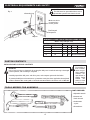 5
5
-
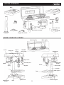 6
6
-
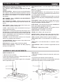 7
7
-
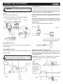 8
8
-
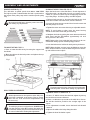 9
9
-
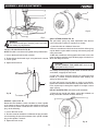 10
10
-
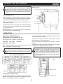 11
11
-
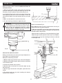 12
12
-
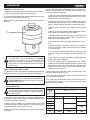 13
13
-
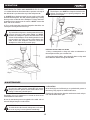 14
14
-
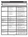 15
15
-
 16
16
-
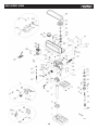 17
17
-
 18
18
-
 19
19
-
 20
20
-
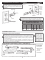 21
21
-
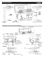 22
22
-
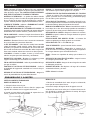 23
23
-
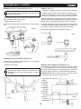 24
24
-
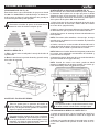 25
25
-
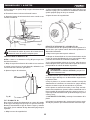 26
26
-
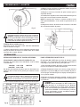 27
27
-
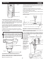 28
28
-
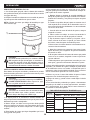 29
29
-
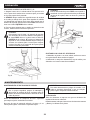 30
30
-
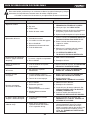 31
31
-
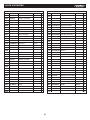 32
32
-
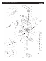 33
33
-
 34
34


KNOVA KN DP-2000 El manual del propietario
- Categoría
- Herramientas eléctricas
- Tipo
- El manual del propietario
en otros idiomas
- English: KNOVA KN DP-2000 Owner's manual
Artículos relacionados
Otros documentos
-
Craftsman 137219120 El manual del propietario
-
-
Hitachi Koki B 16RM Manual de usuario
-
-
RIDGID R1500 Guía del usuario
-
Porter Cable PCB660DP Manual de usuario
-
Craftsman 124.34983 El manual del propietario
-
-
-
Surtek TC658B El manual del propietario