KNOVA KN DP-3000N El manual del propietario
- Categoría
- Destornilladores eléctricos
- Tipo
- El manual del propietario

KN DP-3000N
Variable speed
drill press12”
Taladro de banco, velocidad variable
(300 mm)
We invite you to read
the user manual before
operating your equipment.
Lo invitamos a leer el manual del
usuario antes de operar su equipo.

Table of contents ............................................................. 1
Introduction ...................................................................... 1
Product specications ...................................................... 1
General safety rules ......................................................... 1
Specic rule for the drill press ......................................... 2
Electrical information ....................................................... 3
Know your drill press ....................................................... 4
Assembly and adjustments .............................................. 5
Operation ........................................................................ 10
Maintenance ................................................................... 12
Troubleshooting .............................................................. 13
Parts list (assembly) ....................................................... 14
Parts list (pieces) ............................................................ 15
Exploded view ................................................................. 16
TABLE OF CONTENTS
1
WARNING
INTRODUCTION
Thanks for purchasing the KNOVA Drill Press. We know you are excited to put your tool to work, but rst, please take a
moment to read through the manual. Safe operation of this tool requires that you read and understand this operator’s manual
and all the labels afxed to the tool. This manual provides information regarding potential safety concerns, as well as helpful
assembly and operating instructions for your tool.
Indicates danger, warning, or caution. The safety symbols and the explanations with them deserve
your careful attention and understanding. Always follow the safety precautions to reduce the risk of re,
electric shock or personal injury. However, please note that these instructions and warnings are not substitutes for
proper accident prevention measures.
NOTE: The following safety information is not meant to cover all possible conditions and situations that may occur.
KNOVA reserves the right to change this product and specications at any time without prior notice.
At KNOVA, we are continuously improving our products. If you nd that your tool does not exactly match this manual, please
visit www.knova.com.mx for the most up-to-date manual or contact our customer service at 1-800-70 56682.
Keep this manual available to all users during the entire life of the tool and review it frequently to maximize safety for both
yourself and others.
PRODUCT SPECIFICATIONS
Motor: 120 V, 60 Hz, 5 Amps.
Chuck capacity: 1/32 in - 5/8 in (Ø16 mm)
Spindle travel: 3-5/32 in (80 mm)
Taper: JT3
Speed range: 580 - 3200 RPM (no load)
Swing: 12 in (300 mm)
Table size: 9-1/2 in x 9-1/2 in (240 x 240 mm)
Table tilt: 0º to 45º left and right
Column dia.: 2-1/2 in (65 mm)
Laser: Class IIIA 2.5 mW
Machine height: 36-1/2 in (927 mm)
Gross/net weight: 87.7 lb (39.8 kg) / 83.7 lb (38 kg)
GENERAL SAFETY RULES
WARNING
Read all safety warnings and all
instructions. Failure to follow the warnings and
instructions may result in electric shock, re and/or serious
injury.
Safety is a combination of common sense, staying alert and
knowing how your item works. The term “power tool”
in the warnings refers to your mains-operated (corded) power
tool or battery-operated (cordless) power tool.
WORK AREA SAFETY
1. Keep work area clean and well lit. Cluttered or dark
areas invite accidents.
2. Do not operate power tools in explosive atmospheres,
such as in the presence of ammable liquids, gases or
dust. Power tools create sparks which may ignite the dust
or fumes.
3. Keep children and bystanders away while operating
a power tool. Distractions can cause you to lose control.
SAVE THESE SAFETY INSTRUCTIONS.
ELECTRICAL SAFETY
1. Power tool plugs must match the outlet. Never modify
the plug in any way. Do not use any adapter plugs
with earthed (grounded) power tools. Unmodied plugs
and matching outlets will reduce risk of electric shock.
2. Avoid body contact with earthed or grounded surfaces
such as pipes, radiators, ranges and refrigerators.
There is an increased risk of electric shock if your body
is earthed or grounded.
3. Do not expose power tools to rain or wet conditions.
Water entering a power tool will increase the risk of
electric shock.
4. Do not abuse the cord. Never use the cord for carrying,
pulling or unplugging the power tool. Keep cord away
from heat, oil, sharp edges or moving parts. Damaged or
entangled cords increase the risk of electric shock.
5. When operating a power tool outdoors, use an extension
cord suitable for outdoor use. Use of a cord suitable for
outdoor use reduces the risk of electric shock.

2
GENERAL SAFETY RULES
6. If operating a power tool in a damp location is
unavoidable, use a ground fault circuit interrupter (GFCI)
protected supply. Use of a GFCI reduces the risk of
electric shock.
PERSONAL SAFETY
1. Stay alert, watch what you are doing and use common
sense when operating a power tool. Do not use a power
tool while you are tired or under the inuence of drugs,
alcohol or medication. A moment of inattention while
operating power tools may result in serious personal injury.
2. Use personal protective equipment. Always wear eye
protection. Protective equipment such as a respiratory
mask, non-skid safety shoes and hearing protection used
for appropriate conditions will reduce the risk of personal
injury.
3. Prevent unintentional starting. Ensure the switch is in the
off-position before connecting to power source and/or
battery pack, picking up or carrying the tool. Carrying
power tools with your nger on the switch or energizing
power tools that have the switch on invites accidents.
4. Remove any adjusting key or wrench before turning the
power tool on. A wrench or a key left attached to a
rotating part of the power tool may result in personal injury.
5. Do not overreach. Keep proper footing and balance at all
times. This enables better control of the power tool in
unexpected situations.
6. Dress properly. Do not wear loose clothing or jewelry.
Keep your hair and clothing away from moving parts.
Loose clothes, jewelry or long hair can be caught in moving
parts.
7. If devices are provided for the connection of dust
extraction and collection facilities, ensure these are
connected and properly used. Use of dust collection can
reduce dust-related hazards.
POWER TOOL USE AND CARE
1. Do not force the power tool. Use the correct power tool
for your application. The correct power tool will do the job
better and safer at the rate for which it was designed.
2. Do not use the power tool if the switch does not turn it
on and off. Any power tool that cannot be controlled with
the switch is dangerous and must be repaired.
3. Disconnect the plug from the power source and/or the
battery pack from the power tool before making any
adjustments, changing accessories, or storing power
tools. Such preventive safety measures reduce the risk of
starting the power tool accidentally.
4. Store idle power tools out of the reach of children and do
not allow persons unfamiliar with the power tool or these
instructions to operate the power tool. Power tools are
dangerous in the hands of untrained users.
5. Maintain power tools. Check for misalignment or binding
of moving parts, breakage of parts and any other
condition that may affect the power tool’s operation. If
damaged, have the power tool repaired before use. Many
accidents are caused by poorly maintained power tools.
6. Keep cutting tools sharp and clean. Properly maintained
cutting tools with sharp cutting edges are less likely to
bind and are easier to control.
7. Use the power tool, accessories and tool bits, etc. in
accordance with these instructions, taking into account
the working conditions and the work to be performed.
Use of the power tool for operations different from those
intended could result in a hazardous situation.
8. Use clamps to secure your workpiece to a stable surface.
Holding a workpiece by hand or using your body to support
it may lead to loss of control.
9. KEEP GUARDS IN PLACE and in working order.
SERVICE
1. Have your power tool serviced by a qualied repair
person using only identical replacement parts. This
will ensure that the safety of the power tool is maintained.
CALIFORNIA PROPOSITION 65 WARNING
Some dust created by power sanding, sawing, grinding, drilling,
and other construction activities may contain chemicals,
including lead, known to the State of California to cause
cancer, birth defects, or other reproductive harm. Wash hands
after handling. Some examples of these chemicals are:
• Lead from lead-based paints.
• Crystalline silica from bricks, cement, and other
masonry products.
• Arsenic and chromium from chemically treated lumber.
Your risk from these exposures varies depending on how often
you do this type of work. To reduce your exposure to these
chemicals, work in a well-ventilated area with approved safety
equipment such as dust masks specially designed to lter out
microscopic particles.
SPECIFIC RULES FOR THE DRILL PRESS
WARNING
Do not let comfort or familiarity with the
product replace strict adherence to product safety
rules. Failure to follow the safety instructions may result in
serious personal injury.
1. TOOL PURPOSE. This drill press is designed to drill
through metal and wood. Drilling through other materials
could result in re, injury, or damage to the workpiece.
Using the machine for any other purpose for which it is not
designed may result in serious injuries, machine damage
and voiding of the warranty.
2. MACHINE MOUNTING. For operation safety, the drill
press must be securely mounted onto a at and stable
surface or stand.
3. PERSONAL SAFETY.
• Always wear ANSI Z87.1-approved glasses with side
shields, hearing protection and a dust mask.
• Do not wear loose clothing or jewelry, as they might get
drawn in by the tool. Tie back long hair.
• DO NOT wear gloves while operating this machine.
4. Electric Cords. Keep cords away from heat, oil, sharp
edges, and moving parts of the tool. Have an electrician
replace or repair damaged or worn cords immediately.
5. TOOL & ACCESSORIES INSPECTION. Before
operation, check the tool and accessories for any damage
or missing parts. Do not use the tool if any part is missing
or damaged. Make sure all adjustments are correct and all
connections are tight. Keep all guards in place.

3
SPECIFIC RULES FOR THE DRILL PRESS
6. DRILLING ACCESSORIES.
• Make sure the drill bit is not damaged before use; only
use undamaged drill bits
• Make sure the drill bit is securely locked in the chuck
before turning ON.
• Make sure the chuck key is removed from the chuck
before turning ON.
• Use clamps or a vise (not included) to secure a
workpiece to the table. This will prevent the workpiece
from rotating with the drill bit.
7. Make sure the table lock is tightened before starting
the drill press.
8. WORKPIECE REQUIREMENTS.
• Only stand workpieces sturdy enough to withstand
the force of the drill bit.
• Inspect the workpiece for imperfections, nails, staples,
etc. before drilling. Never drill stock that has
questionable imperfections or embedded foreign objects.
• Do not drill materials without a at surface unless a
suitable support is used (clamp or vise).
9. PREVENTING ACCIDENTAL STARTING. Make sure the
power switch is in the OFF position prior to plugging in the
machine. Always make sure the power switch is in the OFF
position and the machine is unplugged when doing any
cleaning, assembly, setup operations, or when not in use.
10. Do not operate this tool until it is completely assembled
and installed according to the instructions.
11. Remove scrap pieces and other objects from the table
before turning ON the drill press.
12. DRILLING THE WORKPIECE.
• Allow spindle to reach full speed before drilling
the workpiece.
• Never start the machine with the drill bit pressed
against the workpiece.
• Adjust the table or depth stop to avoid drilling into
the table.
• Set the drill press to the speed that is appropriate
for the material being drilled.
GROUNDING INSTRUCTIONS
In the event of a malfunction or breakdown, grounding
provides the path of least resistance for an electric current
and reduces the risk of electric shock. This tool is equipped
with an electric cord that has an equipment grounding
conductor and a grounding plug. The plug MUST be plugged
into a matching outlet that is properly installed and grounded
in accordance with ALL local codes and ordinances.
1. Do not modify the plug provided. If it will not t the outlet,
have the proper outlet installed by a licensed electrician.
2. Improper connection of the equipment grounding
conductor can result in electric shock. The conductor with
the green insulation (with or without yellow stripes) is the
equipment grounding conductor. If repair or replacement
of the electric cord or plug is necessary, DO NOT connect
the equipment grounding conductor to a live terminal.
13. Do not touch moving pieces. Keep hands away from
the drill bit during operation. If cleaning is necessary, turn
off the machine and use a brush to remove sawdust and
chips instead of your hands.
14. Never perform layout, assembly or set-up work on
the table while the machine is ON.
15. After turning off the drill press, wait until the spindle
comes to a complete stop before touching the workpiece.
Always turn the drill OFF before removing scrap from
the table.
16. Before leaving the machine, always turn OFF and unplug
the machine, remove the drill bit, and clean the table.
Turn Off and unplug the machine before cleaning, making
adjustments or changing drill bits. Accidental start-ups
may occur if the tool is plugged in during an accessory
change or adjustment.
17. CLEANING. Never use solvents to clean plastic parts.
Solvents could dissolve or otherwise damage the material.
Use only a soft damp cloth to clean plastic parts.
18. REPLACEMENTS. Should any component of your drill
press be missing/damaged or fail in any way, shut OFF
the switch and remove the plug from power supply outlet.
Replace the missing, damaged, or failed parts using only
identical replacement parts before resuming operation.
CALIFORNIA PROPOSITION 65 WARNING
Some dust created by power sanding, sawing, grinding,
drilling, and other construction activities may contain
chemicals, including lead, known to the State of California to
cause cancer, birth defects, or other reproductive harm. Wash
hands after handling. Some examples of these chemicals are:
• Lead from lead-based paints.
• Crystalline silica from bricks, cement, and other
masonry products.
• Arsenic and chromium from chemically treated lumber.
Your risk from these exposures varies depending on how often
you do this type of work. To reduce your exposure to these
chemicals, work in a well-ventilated area with approved safety
equipment such as dust masks specially designed to lter out
microscopic particles.
These safety instructions can’t possibly warn of every
scenario that may arise with this tool, so always make sure
to stay alert and use common sense during operation.
ELECTRICAL INFORMATION
3. Check with a licensed electrician or service personnel if
you do not completely understand the grounding
instructions or whether the tool is properly grounded.
4. Use only three-wire extension cords that have
three-pronged plugs and outlets that accept the tool’s plug
(INSERT CR). Repair or replace a damaged or worn cord
immediately.
CAUTION! In all cases,
make certain the outlet
in question is properly
grounded. If you are not
sure, have a licensed
electrician check
the outlet.
Fig. 1

4
ELECTRICAL INFORMATION
GUIDELINES AND RECOMMENDATIONS
FOR EXTENSION CORDS
When using an extension cord, be sure to use one heavy
enough to carry the current your product will draw. An
undersized cord will cause a drop in line voltage resulting in
loss of power and overheating. The table below shows the
correct size to be used according to cord length and ampere
rating. When in doubt, use a heavier cord. The smaller
the gauge number, the heavier the cord.
Various drill bits,
vises, clamps and
other accessories
can be purchased
from www.knova.com.mx
TOOL PURPOSE
Drill presses are mainly used to drill clean, precise cylindrical holes into workpieces or enlarge existing holes. You may also
nd other uses for your drill press such as reaming, countersinking, counter boring, tapping, etc. Refer to the diagram below
and on page 10 to become familiarized with the parts and controls of your drill press.
AMPERAGE
5A
25 ft.
18 gauge
REQUIRED GAUGE FOR EXTENSION CORDS
50 ft.
16 gauge
100 ft.
16 gauge
150 ft.
14 gauge
1. Examine extension cord before use. Make sure your
extension cord is properly wired and in good condition.
Always replace a damaged extension cord or have it
repaired by a qualied person before using it.
2. Do not abuse extension cord. Do not pull on cord to
disconnect from receptacle; always disconnect by pulling
on plug. Disconnect the extension cord from the
receptacle before disconnecting the product from the
extension cord. Protect your extension cords from sharp
objects, excessive heat and damp/wet areas.
3. Use a separate electrical circuit for your tool. This circuit
must not be less than a 12-gauge wire and should be
protected with a 15A time-delayed fuse. Before connecting
the motor to the power line, make sure the switch is in the
OFF position and the electric current is rated the same as
the current stamped on the motor nameplate. Running at
a lower voltage will damage the motor.
KNOW YOUR DRILL PRESS
22
21
20
19
16
15
5
4
3
2
1
6
18
17
14
13
1. Digital speed readout
2. ON / OFF switch
3. Depth scale
4. Chuck
5. Table
6. Feed handles
7. Housing cover screw
8. Housing cover
9. Column
10. Rack
11. Crank handle
12. Column support
13. Base
14. Table lock handle
15. Bevel lock bolt
16. Bevel scale
17. Laser ON / OFF switch
18. LED worklight switch
19. Extension wing with
integrated rollers
20. Support lock handle
21. Speed control handle
22. Power cord
23. Chuck key storage
78
23
9
10
11
12
Fig. 2

5
ASSEMBLY AND ADJUSTMENTS
UNPACKING
With the help of a friend or trustworthy foe, carefully remove the drill press from the packaging. Make sure to take out all
contents and accessories. Do not discard the packaging until the drill press is completely assembled.
Before using the drill press, you must assemble the unit using the instructions in this section. Check your packing list against
the diagram below. If any part is damaged or missing, please contact our customer service at 55 5272 4808, M-F 8-5 CST or
e-mail us at [email protected]
CLEANING THE WORK TABLE SURFACE
Your drill press comes protected with a layer of anti-rust coating on its exposed (non-painted) metal surfaces. Clean the
rust-protected surfaces using a soft cloth, moistened with kerosene. Do not use gasoline, or cellulose-based solvents such
as paint thinner or lacquer thinner, as these will damage the painted surfaces. After cleaning, apply a light coat of
good-quality paste wax to the table and column to prevent rust. Wipe all parts thoroughly with a clean, dry cloth.
PACKING LIST
Check your packing list against the diagram below. If any part is damaged or missing, please contact our customer service at
55 5272 4808, M-F 8-5 CST or e-mail us at [email protected] and DO NOT plug the drill press in or turn ON.
1
14
17
16
15
12
13
11
10
9
8
3
4
5
6
7
1. Head / motor assembly
2. Column assembly
3. Table
4. Base
5. Chuck arbor
6. Chuck
7. Extension wing
with integrated rollers
8. Chuck key
9. Wing knobs (2)
10. Table lock handles (2)
11. Hex head bolts (4)
12. Table crank handle
13. Hex wrenches (3mm & 4mm)
14. Feed handles (3)
15. LED bulb
16. Wedge
17. Speed handle
2

ASSEMBLY AND ADJUSTMENTS
6
WARNING
If any part is missing or damaged, do not
plug the drill press in until the missing or damaged
part is repaired or replaced.
The column assembly (column, column support, rack, rack
collar, and table support bracket) must be attached to the
base. The table and table support handles must be attached to
the table support bracket. The head must be attached to the
column.
Tools needed for assembly (not included):
• Adjustable wrench
• Hammer and block of wood, OR dead blow hammer,
OR rubber mallet
• Screwdriver
ATTACHING COLUMN TO BASE (FIG. 3)
1. Place the column assembly (Fig. 3 - 1) on the base
(Fig. 3 - 2), aligning the column support holes to
the base holes.
2. Install a hex head bolt
(Fig. 3 - 3) in each column
support hole and tighten
bolts using the adjustable
wrench (not included).
TABLE TO TABLE SUPPORT BRACKET (FIG. 4)
1. Place the crank handle (Fig 4 - 1) onto the shaft (Fig 4 - 2)
of the table bracket so the at of the shaft is under the set
screw (Fig. 4 - 3). Tighten the set screw.
2. Thread the table lock handle (Fig. 4 - 4) into the front of
the table support bracket.
FEED HANDLES (FIG. 6)
1. Insert the three feed handles (Fig. 6 - 1) into the threaded
openings on the feed hub (Fig. 6 - 2).
2. Manually tighten the handles into the openings. Use an
adjustable wrench (not included) to grip the ats on the
handles and fully tighten them.
NOTE: When using the drill press, one or two of the feed
handles may be removed
if an unusually-shaped
workpiece interferes
with the handle rotation.
Fig. 3
1
2
3. Thread
the table
support lock
handle into the rear of the table
support bracket (not shown).
4. Position the table (Fig. 4 - 5) in
the same direction as the base.
Install the table
and tighten
the table
lock handle
(Fig. 4 - 4)
and support
lock handle.
5
42
3
1
DRILL PRESS HEAD TO COLUMN (FIG. 5)
WARNING
The drill press head is heavy. To avoid
injury, two people should lift it into position.
1. Carefully lift the drill press head assembly (Fig. 5 - 1) and
position it over the column (Fig. 5 - 2).
2. Place the mounting opening (Fig. 5 - 3) on the drill press
head over the top of the column. Make sure the drill press
head is seated properly on the column.
3. Align the direction of the drill press head with the direction
of the base and the table.
4. Tighten the set screw (Fig. 5 - 4) using the included hex
wrench.
Fig. 4
1
34
2
Fig. 5
Fig. 6
1
2

ASSEMBLY AND ADJUSTMENTS
7
SPEED HANDLE (FIG. 7)
1. Insert the speed handle (Fig. 7 - 1) into the threaded
opening on the speed hub (Fig. 7 - 2).
2. Manually tighten the handle into the openings. Use an
adjustable wrench (not included) to grip the ats on the
handles and fully tighten them.
2
1Fig. 7
MOUNTING THE DRILL PRESS (FIG. 8)
The drill press must be securely fastened through the
mounting holes (Fig. 8 - 1) to a stand or workbench with
heavy-duty fasteners (not included). This will prevent the drill
press from tipping over, sliding, or walking during operation.
IMPORTANT: If the stand or workbench has a tendency to
move during operation, fasten the workbench securely to the
oor.
LED BULB
An LED bulb has been assembled in the socket of the head.
WARNING
To reduce risk of re, DO NOT use a
light bulb greater than 40 watts. When changing the
light bulb, always check that the power switch is in the OFF
position and the plug is disconnected from its power source.
1
1
Fig. 8
INSTALL THE CHUCK (FIG. 9)
1. Inspect and clean the taper hole in the chuck (Fig. 9 - 1)
and the spindle (Fig. 9 - 2). Remove all grease, coatings,
and particles from the chuck and spindle surfaces with a
clean cloth.
2. Open the chuck jaws (Fig. 9 - 3) by manually turning
the chuck barrel clockwise. Make sure the jaws are
completely recessed inside the chuck.
3. Insert the chuck arbor (Fig. 9 - 4) into the opening at
the top of the chuck.
4. Insert the arbor into the spindle. Rotate it until the tang of
the arbor (the ats on the end) is aligned with the slot in
the spindle, and the chuck and arbor can be pushed
upwards. Seat the chuck by placing a block of wood
(Fig. 9 - 5, not included) below the chuck and rmly
tapping the wood once with a hammer. Alternatively,
rmly tap the chuck once with a rubber mallet or
dead-blow hammer (not included).
5. If the chuck or arbor fail to seat properly, they may not be
clean enough. Remove them and
thoroughly clean the mating surfaces,
then try again. Ensure all dust, debris,
and liquids
are
removed
from the
surfaces,
and that
neither
surface is
damaged.
2
4
1
3
5
6
Fig. 9
CAUTION
To avoid damaging
the chuck, make sure the jaws
are completely recessed
into the chuck. Do not
use a metal hammer to
drive the chuck onto the arbor
or into the spindle.
REMOVE THE CHUCK (FIG. 10)
1. Turn the feed handles (1) to lower the chuck (2) to
the lowest position.
2. Insert the drift key (3) into the opening in the quill. Gently
tap on the wedge using a rubber mallet (4) (not included).
The chuck and arbor will drop out.
NOTE: To avoid possible damage to the drill or chuck, be
prepared to catch the chuck as it falls.
Fig. 10
1
2
3
4

8
ASSEMBLY AND ADJUSTMENTS
RAISE OR LOWER THE TABLE (FIG. 11)
1. Loosen the support lock handle (Fig. 11 - 1) and turn
the crank handle (Fig. 11 - 2) until the table is at
the desired height.
2. Tighten the support lock handle before drilling.
ROTATE THE TABLE (FIG. 11)
1. Loosen the support lock handle (Fig. 11 - 1) and turn
the table around the column to the desired position.
NOTE: The rack should rotate around
the column with
the table support
bracket. If the rack
binds and does not
rotate, slightly
loosen the set
screw in the rack
collar.
2. Tighten the
support lock
before drilling.
TILT THE TABLE (FIG. 12A)
1. Loosen the bevel lock bolt (Fig. 12A - 1)
by turning it counterclockwise with an
adjustable wrench (not included).
2. Tilt the table to the desired angle,
using the bevel scale (Fig. 12A - 2) as a basic guide.
3. Re-tighten the bevel lock bolt.
ADJUST TABLE TO
BE HORIZONTAL (FIG. 12A)
1. Loosen the bevel lock bolt
(Fig. 12A - 1).
2. Realign the table to the 0°
setting on the bevel scale
(Fig. 12A - 2).
3. Tighten the bevel
lock bolt with the
adjustment wrench.
INSTALL THE TABLE
EXTENSION (FIG. 12B)
1. Insert the two rods
(Fig. 12B - 1) of
the table extension
into the two channels
(Fig. 12B - 2) at
the side of the table.
2. Place a wing knob
(Fig. 12B - 3) in the
opening on the bottom
of each channel and
tighten to secure the
extension to the table.
Fig. 11
Fig. 12A
Fig. 14
2
1
2
1
2
3
1
Fig. 12B
WARNING
To avoid
injury, make sure the
chuck key is removed from
the chuck before starting
any drilling operation.
INSTALLING A DRILL BIT (FIG. 13)
1. Place the chuck key (Fig. 13 - 1) into the side keyhole of
the chuck (Fig. 13 - 2), meshing the key with the gear
teeth.
2. Turn the chuck key counterclockwise to open the chuck
jaws (Fig. 13 - 3).
3. Insert a drill bit (Fig. 13 - 4) into the chuck far enough to
obtain the maximum grip of the chuck jaws on the bit
shank.
4. Center the drill bit in the chuck jaws before the nal
tightening of the chuck.
5. Tighten the chuck jaws using the chuck key to ensure that
the drill bit will not slip while drilling. Tighten all three
keyholes on the chuck.
6. Remove the
chuck key and
place it back on
the onboard
storage.
Fig. 13
12
3
4
SQUARING TABLE TO THE DRILL BIT (FIG. 14)
1. Insert a 3” long drill bit (Fig. 14 - 1) into the chuck
(Fig. 14 - 2) and tighten the jaws with the chuck key.
2. Raise the table with the crank handle (Fig. 14 - 3).
Lock the table (Fig. 14 - 4) approximately 1” below
the drill bit.
3. Place a combination square (Fig. 15 - 5) (not included)
on the table as shown, placing the long straight edge of
the combination square against the drill bit. Make sure
the drill bit is parallel / aligned exactly to the straight
edge of the square.
4. If an adjustment is needed, loosen the bevel lock bolt
(Fig. 14 - 6) with a wrench.
5. Tilt the table slightly, until
the combination straight
edge is aligned perfectly
with the drill bit.
6. Tighten the bevel
lock when square.
2
1
5
4
63

ASSEMBLY AND ADJUSTMENTS
9
ADJUSTING THE LASER (FIG. 15 & 16)
WARNING
Do not stare directly at the laser beam.
Observe all safety rules.
• Never aim the beam at a person or an object other
than the workpiece.
• Always make sure the laser beam is aimed at a
workpiece that does not have reective surfaces,
as the laser beam could reect into your eyes or
the eyes of others.
1. Place a workpiece on the table.
2. Turn the laser switch (Fig. 15 - 1) to the ON position.
3. Lower the drill bit to meet the workpiece (Fig. 16 - 2).
The two laser lines should cross where the drill meets
the workpiece.
4. If the laser needs to
be adjusted:
a. Using the included
3 mm hex key, turn
the laser adjustment
set screws
(Fig. 15 - 3)
counterclockwise.
There is one of each
side of the head.
b. Rotate the laser light
housing (Fig. 15 - 4)
until the two laser lines
intersect where the drill
meets the workpiece.
5. Re-tighten the adjustment
set screws (Fig. 15 - 3).
13
4
4
Fig. 15
4
Fig. 16
SPINDLE RETURN SPRING (FIG. 17)
The spindle is equipped with an auto-return mechanism. The
main components are a spring and a notched housing. The
spring was properly adjusted at the factory and should not be
readjusted unless absolutely necessary.
1. Unplug the drill press.
2. Place a screwdriver into the loop (Fig. 17 - 1) to hold the
spring in place.
3. Loosen the two housing nuts (Fig. 17 - 2) approximately
1/4” (6 mm). Do not remove the nuts from the threaded
shaft. Do not allow the spring or spring housing to slip out
of control.
4. While rmly holding the spring housing (Fig. 17 - 3),
carefully pull spring housing out until it clears the raised
stop (Fig. 17 - 4).
5. Turn the housing so that the next notch (Fig. 17 - 5) is
engaged with the raised stop (Fig. 17 - 4).
• To increase the spindle return tension, turn the spring
housing counter-clockwise.
• To decrease the tension, turn the spring housing
clockwise.
6. Tighten the two
housing nuts. Do not
overtighten the two
nuts. If the nuts
are tightened too
much, the
movement of
the spindle and
feed handles
will become
sluggish.
Move the spindle to the lowest downward position and hold in
place. Try to make the spindle revolve around its axis while
also moving it with a side motion. If there is too much “play”,
proceed as follows:
1. Loosen the outer nut
(Fig. 18 - 1) about
1/8 inch.
2. Without obstructing
the upward and
downward motion
of the spindle, turn
the screw
(Fig. 18 - 2)
clockwise to
eliminate the “play.”
NOTE: A little bit
of “play” is normal.
3. Tighten the lock
nut (Fig. 18 - 1).
1. To turn the drill press ON, insert the yellow safety key
(Fig. 19 - 1) into the switch housing (Fig. 19 - 2). As a
safety feature, the switch cannot be turned ON without
the safety key.
2. Flip the switch upward to the ON position.
3. To turn the drill press OFF, ip the switch downward.
4. To lock the switch in the OFF position, remove the safety
key (Fig. 19 - 1) from the switch. Store the safety key in a
safe place away from the reach of children.
14
5
3
2
NOTE:
Adjustments for
the correct
function of
your drill
press return
spring have been
done by the factory.
Please do not modify them. However, prolonged use of
the drill press may make some readjustments necessary.
ANGULAR “PLAY” OF THE SPINDLE (FIG. 18)
DRILL PRESS ON / OFF SWITCH (FIG. 19)
Fig. 17
2
1
Fig. 18

ASSEMBLY AND ADJUSTMENTS
10
3
5
4
3
1
2
Fig. 19
The light switch (Fig. 19 - 3)
is located on the lamp cover.
The laser switch (Fig. 19 - 4)
is located below the ON/OFF
switch on the right.
LIGHT & LASER LINE ON/OFF SWITCHES (FIG. 19)
Always place a piece of backup material (Fig. 20 - 1)
(wood, plywood, etc.) on the table underneath the workpiece
(Fig. 20 - 2). This will prevent splintering on the underside of
the workpiece as the drill bit
breaks through. To keep
the material from
spinning out of control,
it must contact the left
side (Fig. 20 - 3) of
the column as illustrated,
or be clamped
(Fig. 20 - 4; not included)
to the table.
NOTE: For small
workpieces that
cannot be clamped
to the table, use a
drill press vise
(not included).
The vise must be
clamped or bolted
to the table to
avoid injury.
POSITION THE TABLE AND WORKPIECE (FIG. 20)
4
2
1
3
Fig. 20
OPERATION
GENERAL DRILLING GUIDELINES - DRILLING A HOLE
WARNING
To prevent the workpiece and the backup
material from slipping from your hand while drilling,
position the workpiece and backup material to the left side
of the column. If the workpiece and the backup material are
not long enough to reach the column, clamp the workpiece
and backup material to the table. Failure to do this could
result in personal injury.
1. Mark where you want to drill in workpiece by using a
center punch or a sharp nail or turn ON the laser to mark
your drilling point.
2. Before turning the drill press ON, turn the feed handles
to bring the drill bit down. Line the drill bit tip up with the
mark. Clamp the workpiece in place.
3. Turn ON the drill press and pull down on the feed handles
with the appropriate force needed to allow the drill bit to
drill the material.
NOTE: Feeding too slowly might cause the drill bit to turn
in the chuck. Feeding too rapidly might stop the motor,
cause the belt to slip, force the workpiece loose, or break
the drill bit. Practice with scrap material to get the feel of
the machine before attempting to do any drilling operation.
ADJUST THE DRILLING DEPTH (FIG. 21A)
The depth gauge controls the maximum distance the drill bit
will move up or down.
TO STOP THE DRILL BIT AT A PRE-MEASURED DEPTH:
1. Rotate the lower depth scale knob (Fig. 21A - 2) until
the bottom of the knob is aligned with the desired depth
mark (Fig. 21A - 5) on the gauge scale.
2. Rotate the depth scale lock knob (Fig. 21A - 1) until it
meets the lower depth scale knob (Fig. 21A - 2). The
chuck will stop after travelling downward to the selected
distance.
TO ADJUST THE QUILL (RETURN) HEIGHT:
To adjust the upward distance the quill (shaft that moves up
and down) can travel:
1. Turn the feed handles until the quill
is at the desired height
and hold it there.
2. Rotate the lower
depth knob
(Fig. 21A - 3)
until it rests
against the
bottom of the
metal gauge
support
(Fig. 21A - 4).
Drilling an unmeasured
blind hole (not all the way
through the workpiece)
to a given depth can be
done two ways: using the
depth scale method or workpiece method.
DEPTH SCALE METHOD (FIG. 21B)
1. Make sure the 0 (in or mm) mark on the depth gauge rests
at the top edge of the metal support (Fig. 21B - 4) when
the quill is fully retracted.
2. Put the workpiece on the table and raise the table until
the tip of the drill bit just touches the top of the workpiece.
Lock the table in place.
3. Determine the drill depth for this workpiece.
4. Rotate the depth knob (Fig. 21B - 2) until it is aligned with
the desired depth mark (Fig. 21B - 3) (for example, 1”) on
the gauge scale.
5. The chuck will be stopped at the distance selected on
the depth scale.
3
1
2
5
4
Fig. 21A

OPERATION
11
1
2
4
3
Fig. 21B
WORKPIECE METHOD (FIG. 21 & 22)
1. Mark the desired depth (Fig. 22 - 5) of the drill hole on
the side of the workpiece.
2. With the drill press in the OFF position, bring the drill bit
(Fig. 22 - 6) down until the tip is even with the mark.
3. Holding the feed handles at this position, rotate the depth
knob (Fig. 21 - 2) until it meets the metal support.
4. The chuck and the drill bit will now be stopped at
the distance selected on the depth scale.
DRILLING SPEEDS
There are a few important factors to keep in mind when
determining the best drilling speed:
• Material type
• Hole size
• Drill bit or
cutter type
• Quality
desired
Smaller drill bits
require greater
speed than larger
drill bits. Softer
materials require
greater speed than
harder materials.
See page 12
for recommended
speeds for particular
materials.
DRILLING METAL
• Use metal-piercing twist drill bits.
• It is always necessary to lubricate the tip of the drill with
oil to prevent overheating of the drill bit.
DRILLING WOOD
• Brad point bits are preferred. Metal piercing twist bits
may be used on wood.
• Do not use auger bits. Auger bits turn so rapidly that
they can lift the workpiece off of the table and whirl
it around.
• Always protect the drill bit by positioning the table so
that the drill bit will enter the center hole when drilling
through the workpiece.
• To prevent splintering, feed the drill bit slowly right as
the bit is about to cut through to the backside of
the workpiece.
• To reduce splintering and protect the point of the bit,
use scrap wood as a backing or a base block under
the workpiece.
FEEDING THE DRILL BIT
• Pull down on the feed handles with only enough force to
allow the drill bit to cut.
• Feeding too rapidly might stall the motor, cause the belt
to slip, damage the workpiece, or break the drill bit.
• Feeding too slowly will cause the drill bit to heat up and
burn the workpiece.
MECHANICAL VARIABLE SPEED (FIG. 23)
This is a mechanical variable speed drill press. To increase or
decrease the speed when operating, raise or lower the speed
handle (Fig. 23 - 1). Use the following table to determine the
recommended
speed for the drill
size you are using
and the type of
material you are to
drill. While drilling,
check the speed
on the digital speed
readout (Fig. 23 - 2)
located at the front
of the drill press.
Fig. 22
5
6
• All metal workpieces should be clamped down securely.
Any tilting, twisting, or shifting causes a rough drill hole,
and increases the potential of drill bit breakage.
• Never hold a metal workpiece with your bare hands. The
cutting edge of the drill bit may seize the workpiece and
throw it, causing serious injury. The drill bit will break if
the metal piece suddenly hits the column.
• If the metal is at, clamp a piece of wood under it to
prevent turning. If it cannot be laid at on the table,
then it should be blocked and clamped.
2
1
Fig. 23

OPERATION
12
DRILL BIT SIZE RECOMMENDATIONS
Recommended speed for drill bit size and materials
RPM Wood Aluminum, Zinc, Brass Iron, Steel
3/32 in.
5/32 in.
1/4 in.
3/8 in.
5/8 in.
2.4 mm
4 mm
6.4 mm
9.5 mm
16 mm
7/32 in.
11/32 in.
15/32 in.
11/16 in.
3/4 in.
5.6 mm
8.75 mm
12 mm
17.5 mm
19 mm
3/8 in.
5/8 in.
7/8 in.
1-1/4 in.
1-5/8 in.
9.5 mm
16 mm
22 mm
31.75 mm
41.4 mm
2000 to 3200
1400 to 2000
1000 to 1400
800 to 1000
580 to 800
REPLACING THE BELT (FIG. 24)
WARNING
WARNING
Disconnect the drill press from the power
source before replacing the belt.
Do not change the drive speed when
the drill press is turned off.
Belt tension and drill press speed is controlled by automatic
adjustments made to the diameter of the front spindle when
the speed handle is moved.
NOTE: See page 11 for information on the variable speed
function of this drill press.
1. Plug in the drill press and turn it ON. Adjust the speed to
the highest setting, then turn the drill press OFF and
unplug it.
2. Open the belt cover (remove the Phillips-head screw from
the right side, then open the lid.
3. Press down on the bottom side of the motor pulley. This
will loosen the belt tension. Work the belt off the pulleys.
4. Place the new belt on the motor pulley, then press down
on the bottom side of the pulley as before and get the belt
as close to the motor shaft as possible. Make sure
the bottom side of the pulley is pushed fully downward.
ROUTINE INSPECTION
Before each use, inspect the general condition of the tool.
If any of these following conditions exist, do not use until parts
are replaced.
CHECK FOR:
• Loose hardware or improper mounting,
• Misalignment
• Damaged cord/electrical wiring,
• Cracked or broken parts, and
• Any other condition that may affect its safe operation
CLEANING & STORAGE
1. After every operation, use a vacuum to remove sawdust or
metal shavings from the tool surfaces, motor housing and
work area. Keep the ventilation openings free from dust
and debris to prevent the motor from overheating.
2. Wipe the tool surfaces clean with a soft cloth or brush.
Make sure water does not get into the tool.
3. Apply a light coat of paste wax to the column and table to
help keep these surfaces clean and rust free.
4. Store the tool in a clean and dry place away from
the reach of children.
LUBRICATION
The ball bearings in the spindle and the V-belt pulley assembly
are greased and permanently sealed, and require no
lubrication. Pull the spindle down and oil the quill moderately
every three months.
Lubricate the table bracket and locking knobs if they become
difcult to use.
PRODUCT DISPOSAL
Used power tools should not be disposed of together with
household waste. This product contains electronic components
that should be recycled. Please take this product to your local
recycling facility for responsible disposal and to minimize its
environmental impact.
5. Work the belt around the spindle pulley. The belt will not
be taut, but will self-seat later.
6. Close and secure the belt cover.
7. Plug in and turn ON the drill press. The belt will self-seat
and achieve proper tension on its own.
1
3
2
4
MAINTENANCE
WARNING
WARNING
To avoid accidents, turn OFF and unplug
the tool from the electrical outlet before cleaning,
adjusting, or performing any maintenance or lubrication work.
Any attempt to repair or replace
electrical parts on this tool may be hazardous.
Servicing of the tool must be performed by a qualied
technician. When servicing, use only identical WEN
replacement parts. Use of other parts may be hazardous
or induce product failure.
CAUTION
Most plastics are susceptible to damage
from various types of commercial solvents. Do not
use any solvents or cleaning products that could damage the
plastic parts. Some of these include but are not limited to:
gasoline, carbon tetrachloride, chlorinated cleaning solvents,
and household detergents that contain ammonia.

TROUBLESHOOTING
13
Drill bit binds in
the workpiece
Spindle returns too
slowly or too quickly
Noisy operation
or excessive
vibration
The drill bit burns
or smokes
Excessive drill
run out or
wobble; drilled
hole is not round
Chuck falls
off spindle
Motor will
not run
Motor stalls
1) The workpiece is pinching the bit
2) Excessive feed pressure
1) Defective or broken switch
2) Defective or damaged power cord
3) Open circuit, loose connections,
or burned out motor
4) Low voltage
5) Bad starting capacitor
6) Worn centrifugal switch contacts
1) Incorrect belt tension
2) Dry spindle
3) Loose spindle pulley
4) Loose motor pulley
5) Seized motor pulley
1) Drilling at the incorrect speed
2) The wood chips are not coming
out of the hole
3) Dull drill bit
4) Feeding the workpiece too slowly
5) Not lubricated
1) Bent drill bit
2) Bit improperly installed in the chuck
3) Worn spindle bearings
4) Lengths of cutting utes or angles not
appropriate for the hardness of the
wood grain
5) Chuck not properly installed
1) Short circuit in motor
2) Incorrect fuses or circuit breakers
3) Overloaded circuit
4) Low voltage
1) Contact customer service at 01 800 70 56682.
2) Contact customer service at 01 800 70 56682.
3) Contact customer service at 01 800 70 56682.
4) Check the power line for the proper voltage. Use
another circuit or have a qualied electrician upgrade
the service.
5) Contact customer service at 01 800 70 56682.
6) Contact customer service at 01 800 70 56682.
1) Adjust the belt tension.
(See REPLACE THE BELT section)
2) Lubricate the spindle.
3) Tighten the set screws on the side of the spindle pulley.
4) Tighten the set screws on the side of the motor pulley.
5) Lubricate motor pulley and motor shaft; ensure that
pulley opens and closes when machine is ON and
speed is adjusted.
1) Change the speed.
2) Retract the drill bit frequently to clear the chips.
3) Resharpen or replace the drill bit.
4) Feed fast enough to cut the workpiece.
5) Lubricate the drill bit with cutting oil or motor oil.
1) Contact customer service at 01 800 70 56682.
2) Replace with correct fuse or circuit breaker for
the circuit.
3) Turn off other machines and retry.
4) Check the power line for the proper voltage.
Use another circuit or have a qualied electrician
upgrade the service.
Coil spring has improper tension
Dirt, grease, or oil on the tapered
surface on the spindle or in the chuck
1) Support or clamp the workpiece.
2) Feed more slowly.
Clean the tapered surface of both the chuck and
spindle with a household detergent.
PROBLEM CAUSE SOLUTION
WARNING
Stop using the tool immediately if any of the following problems occur. Repairs and replacements should
only be performed by an authorized technician. For any questions, please contact our customer service
at 01 800 70 56682 ó 55 5272 4808, M-F 8-5 CST or e-mail us at [email protected]
Adjust the coil spring tension.
See “Spindle Return Spring” on p. 9
1) Replace the drill bit.
2) Reinstall the bit.
3) Bearings may need replacement. Contact customer
service at 01 800 70 56682.
4) Resharpen the drill bit correctly or replace with
the appropriate type.
5) Reinstall the chuck.

14
PARTS LIST (ASSEMBLY)
A - SPINDLE PULLEY ASSEMBLY (PART 4214B-AA)
2 4214B-002 Cam 1
3 4214B-003 Set screw, M8 x 12 2
4 4214B-004 Bearing, 61907 1
5 4214B-005 Spindle movable pulley 1
7 4214B-007 Spindle xed pulley 1
124 4214B-124 Elastic ring, type A, Ø55 1
125 4214B-125 Circlip for shaft, Ø35 1
B - SPINDLE SHAFT ASSEMBLY (PART 4214B-AB)
8 4214B-008 Key, type A, 4 x 4 x 64 1
9 4214B-009 Spindle sleeve 1
10 4214B-010 Bearing, 6203RZ 2
11 4214B-011 Retainer 1
12 4214B-012 Circlip for shaft, Ø17 1
C - SPINDLE ASSEMBLY (PART 4214B-AC)
55 4214B-055 Bearing, 6201RZ 1
56 4214B-056 Rubber washer 1
57 4214B-057 Quill 1
62 4214B-062 Bearing, 6204RZ 1
63 4214B-063 Spindle, MT2 1
72 4214B-1109 Hex nut, M14 1
D - TABLE ASSEMBLY (PART 4214B-AD)
40 4214B-079 Phillips-head screw, M6 x 8 1
41 4214B-041 Flat washer, Ø8 4
42 4214B-042 Work table 1
44 4214B-044 Guide rod 2
45 4214B-045 Roller screw 2
46 4214B-046 Roller support 1
47 4214B-047 Phillips-head screw, M6 x 12 2
48 4214B-048 Roller 1
E - COLUMN ASSEMBLY (PART 4214B-AE)
76 4214B-076 Set screw, M8 x 8 3
104 4214B-104 Column 1
108 4214B-108 Column base 1
F - TABLE SUPPORT ASSEMBLY (PART 4214B-AF)
96 4214B-096 Phillips-head screw, M4 x 8 2
97 4214B-097 Bevel indicator 1
100 4214B-100 Table support 1
101 4214B-101 Worm gear 1
105 4214B-105 Inner gear 1
106 4214B-106 Inner gear shaft 1
NO. QTYPART NO. DESCRIPTION
G - CRANK ASSEMBLY (PART 4214B-AG)
83 4214B-129 Handle 1
99 4214B-1099 Screw M6 x 10 3
102 4214B-102 Crank handle 1
H - LAMP ASSEMBLY (PART 4214B-AH)
92 4214B-1092 Phillips-head screw, M4 x 12 1
93 4214B-093 Lamp socket bracket 1
94 4214B-094 Lamp socket 1
95 4214B-095 LED lamp 1
K - MOTOR PULLEY ASSEMBLY (PART 4214B-AK)
99 4214B-1099 Screw M6 x 10 3
111 4214B-111 Motor xed pulley 1
112 4214B-112 Motor movable pulley 1
L - VARIABLE SPEED HANDLE ASSEMBLY (PART 4214B-AL)
17 4214B-017 Handle knob 4
18 4214B-018 Variable speed handle 1
M - SWITCHBOX ASSEMBLY (PART 4214B-AM)
14 4214B-014 Screw, ST2.9 x 6.5 4
29 4214B-029-01 Digital display PCB 1
30 4214B-030 Switch box 1
31 4214B-031 Phillips-head screw, M5 x 12 3
32 4214B-032 Main switch 1
33 4214B-033 Lamp/laser switch 2
36 4214B-077 Phillips-head screw, M5 x 10 1
N - SCALE COLLAR ASSEMBLY (PART 4214B-AN)
39 4214B-061 Hex nut, M8 1
52 4214B-052 Adjustment nut 4
53 4214B-053 Special washer 1
54 4214B-054 Scale 1
58 4214B-058 Nut M6 1
59 4214B-059 Scale collar 1
60 4214B-060 Screw M6 x 16 1
P - SPEED SENSOR ASSEMBLY (PART 4214B-AP)
13 4214B-013 Screw, M4 x 20 2
14 4214B-014 Screw, ST2.9 x 6.5 4
15 4214B-015 Speed sensor 1
16 4214B-016 Speed sensor base 1
Q - RACK COLLAR ASSEMBLY (PART 4214B-AQ)
98 4214B-098 Rack collar 1
99 4214B-1099 Screw M6 x 10 3
R - SPINDLE HANDLE ASSEMBLY (PART 4214B-AR)
17 4214B-017 Handle knob 4
122 4214B-122 Handle 3
NO. QTYPART NO. DESCRIPTION
NOTE: Parts may only be available in their respective subassemblies. Not all parts may be available for purchase.

PARTS LIST (PIECES)
15
1 4214B-001 Circlip for shaft, Ø24 1
6 4214B-006 Cogged V-belt, 10 x 900 1
19 4214B-019 Lock nut, M10 1
20 4214B-020 Flat washer, Ø10 1
21 4214B-021 Handle seat 1
22 4214B-022 Speed adjustment base 1
23 4214B-023 Gear shaft 1
24 4214B-024 Key, type A, 3 x 3 x 25 1
25 4214B-025 Hex nut, M12 2
26 4214B-026 Coil spring assembly 1
27 4214B-027 Spring bafe 1
28 4214B-028 Bushing 1
34 4214B-1001 Shaft cover 1
35 4214B-079 Phillips-head screw, M6 x 8 1
37 4214B-136 Knob 2
38 4214B-1086 Inner hex bolt, M8 x 6 1
43 4214B-066 Screw, M5 x 12 1
49 4214B-049 Column clamp 1
50 4214B-050 Table arm 1
51 4214B-051 Hex bolt, M12 x 35 1
61 4214B-061 Hex nut, M8 5
64 4214B-064 Chuck arbor, MT2 - JT3 1
65 4214B-065 Chuck, JT3 1
66 4214B-072 Screw, M5 x 16 1
67 4214B-067 Cord clamping plate 2
68 4214B-068 Rubber bushing 2
69 4214B-069 Cord bushing 1
70 4214B-070 Cord clamping hook 1
72 4214B-1109 Hex nut, M14 1
73 4214B-073 Belt housing assembly 1
74 4214B-074 Damping pad 4
75 4214B-075 Spring pin, 6 x 15 2
77 4214B-077 Phillips-head screw, M5 x 10 5
78 4214B-078 Wrench clip 1
NO. QTYPART NO. DESCRIPTION
79 4214B-079 Screw M6 x 8 2
80 4214B-080 Pin 1
Phillips-head screw, M5 x 8,
with spring & at washers
82 4214B-1128 Spring washer, M12 1
84 4214B-084 Star washer Ø5 2
85 4214B-085 Quill set screw 1
86 4214B-086 Head 1
87 4214B-087 Laser 2
88 4214B-088 Rack compression spring 1
89 4214B-089 Rack shaft 1
90 4214B-1085 Rack bushing 1
91 4214B-091 Hex bolt M8 x 12 3
103 4214B-103 Rack 1
107 4214B-107 Hex bolt, M10 x 30 4
109 4214B-109 Base 1
110 4214B-110 Circlip for shaft, Ø14 1
113 4214B-113 Motor compression spring 1
114 4214B-114 Spring base 1
115 4214B-115 Spring washer 1
116 4214B-116 Motor assembly 1
117 4214B-117 Key, Type A, 4 x 4 x 80 1
118 4214B-118 Hex screw, M8 x 16 4
119 4214B-119 Power cord 1
120 4214B-120 Spring washer, Ø8 3
121 4214B-121 Motor plate 1
123 4214B-123 Handle hub 1
126 4214B-131 Sealing rubber strip 4
127 4214B-132 Hex wrench, M3 1
128 4214B-133 Hex wrench, M4 1
129 4214B-134 Chuck key 1
130 4214B-135 Wedge block 1
131 4214B-1096 Wrench 1
NP
4214B-116-1
Capacitor 1
132
4214B-116CC
Capacitor cover 1
136 4214B-136 Table support knob 2
NO. QTYPART NO. DESCRIPTION
81 4214B-081 2

EXPLODED VIEW
16
Variable speed
drill press12”
Taladro de banco,
velocidad variable
(300 mm)
KN AP-3000N

17
TABLA DE CONTENIDOS
Tabla de contenidos ....................................................... 17
Introducción ................................................................... 17
Especicaciones del producto ........................................ 17
Reglas generales de seguridad ...................................... 17
Reglas especicas para taladro de prensa ..................... 19
Información eléctrica ...................................................... 20
Conozca su taladro de prensa ....................................... 21
Montaje y ajustes .......................................................... 21
Operación ...................................................................... 27
Mantenimiento .............................................................. 29
Solución de problemas ................................................... 29
Lista de partes (conjunto) .............................................. 30
Lista de partes (piezas) ................................................. 30
Diagrama de esquema ................................................... 34
ADVERTENCIA
INTRODUCCIÓN
Gracias por comprar el taladro de columna KNOVA. Sabemos que está emocionado de poner su herramienta a trabajar, pero
primero, tómese un momento para leer el manual. La operación segura de esta herramienta requiere que lea y comprenda este
manual del operador y todas las etiquetas adheridas a la herramienta. Este manual proporciona información sobre posibles pro-
blemas de seguridad, así como instrucciones útiles de montaje y funcionamiento para su herramienta.
NOTA: La siguiente información de seguridad no pretende cubrir todas las condiciones y situaciones posibles que pueden
ocurrir.
KNOVA se reserva el derecho de cambiar este producto y sus especicaciones en cualquier momento sin previo aviso.
En KNOVA, estamos mejorando continuamente nuestros productos. Si encuentra que su herramienta no coincide exactamen-
te con este manual, visite www.knova.com.mx para obtener el manual más actualizado o comuníquese con nuestro servicio al
cliente al 1-800-70 56682.
Mantenga este manual disponible para todos los usuarios durante toda la vida útil de la herramienta y revíselo con frecuencia
para maximizar su seguridad y la de los demás.
Indica peligro, advertencia o precaución. Los símbolos de seguridad y las explicaciones que
contienen merecen su cuidadosa atención y comprensión. Siga siempre las precauciones de seguridad para reducir
el riesgo de incendio, descarga eléctrica o lesiones personales. Sin embargo, tenga en cuenta que estas instrucciones y
advertencias no reemplazan las medidas adecuadas de prevención de accidentes.
ESPECIFICACIONES DEL PRODUCTO
REGLAS GENERALES DE SEGURIDAD
ADVERTENCIA
Lea todas las advertencias de
seguridad y todas las instrucciones. El incumplimiento
de las advertencias e instrucciones puede provocar
descargas eléctricas, incendios y/o lesiones graves.
La seguridad es una combinación de sentido común, mantenerse
alerta y saber cómo funciona su artículo. El término
“herramienta eléctrica” en las advertencias se reere a su
herramienta eléctrica operada por la red eléctrica (con cable)
o a su herramienta eléctrica operada por batería (inalámbrica).
SEGURIDAD DEL ÁREA DE TRABAJO
1. Mantenga el área de trabajo limpia y bien iluminada. Las
áreas desordenadas u oscuras invitan a los accidentes.
2. No opere herramientas eléctricas en atmósferas
explosivas, como en presencia de líquidos, gases o polvo
inamables. Las herramientas eléctricas crean chispas
que pueden encender el polvo o los humos.
GUARDE ESTAS INSTRUCCIONES DE SEGURIDAD.
3. Mantenga a los niños y transeúntes alejados mientras
opera una herramienta eléctrica. Las distracciones
pueden hacer que pierda el control.
SEGURIDAD ELÉCTRICA
1. Los enchufes de la herramienta eléctrica deben coincidir
con el tomacorriente. Nunca modique el enchufe de
ninguna manera. No utilice enchufes adaptadores con
herramientas eléctricas conectadas a tierra. Los enchufes
no modicados y los tomacorrientes coincidentes reducirán
el riesgo de descarga eléctrica.
2. Evite el contacto del cuerpo con supercies conectadas
a tierra o conectadas a tierra, como tuberías, radiadores,
estufas y refrigeradores. Existe un mayor riesgo de
descarga eléctrica si su cuerpo está conectado a tierra
o conectado a tierra.
3. No exponga las herramientas eléctricas a la lluvia ni a
la humedad. Si entra agua en una herramienta eléctrica,
aumentará el riesgo de descarga eléctrica.
Motor: 120 V, 60 Hz, 5 Amperes
Capacidad de morsa: 1/32” - 5/8” (Ø16 mm)
Carrera de husillo: 80 mm (3-5/32”)
Cono morse: JT3
Rango de velocidad: 580 - 3200 RPM (sin carga)
Distancia del husillo a la columna:
300 mm (12”)
Mesa de trabajo: 240 x 240 mm (9-1/2” x 9-1/2”)
Inclinación de la mesa: 0º a 45º izquierda y derecha
Diámetro de columna.: 65 mm (2-1/2”)
Láser: Clase IIIA de 2.5mW
Altura total: 927 mm (36-1/2”)
Peso bruto/neto: 39.8 kg (87.7 lb) / 38 kg (83.7 lb)

REGLAS GENERALES DE SEGURIDAD
18
4. No abuses del cable. Nunca utilice el cable para
transportar, tirar o desenchufar la herramienta eléctrica.
Mantenga el cable alejado del calor, el aceite, los bordes
alados o las piezas móviles. Los cables dañados o
enredados aumentan el riesgo de descarga eléctrica.
5. Cuando opere una herramienta eléctrica al aire libre,
use un cable de extensión adecuado para uso al aire
libre. El uso de un cable adecuado para uso en exteriores
reduce el riesgo de descarga eléctrica.
6. Si es inevitable operar una herramienta eléctrica en un
lugar húmedo, use un suministro protegido con interruptor
de circuito de falla a tierra (GFCI). El uso de un GFCI
reduce el riesgo de descarga eléctrica.
SEGURIDAD PERSONAL
1. Manténgase alerta, mire lo que está haciendo y use el
sentido común cuando opere una herramienta eléctrica.
No use una herramienta eléctrica si está cansado o bajo
la inuencia de drogas, alcohol o medicamentos. Un
momento de falta de atención mientras opera herramientas
eléctricas puede resultar en lesiones personales graves.
2. Use equipo de protección personal. Siempre use
protección para los ojos. El equipo de protección, como
una máscara respiratoria, zapatos de seguridad
antideslizantes y protección auditiva, utilizados para
las condiciones apropiadas, reducirán el riesgo de
lesiones personales.
3. Evite el arranque accidental. Asegúrese de que el
interruptor esté en la posición de apagado antes de
conectarlo a la fuente de alimentación y/o al paquete de
baterías, levantar o transportar la herramienta.
Transportar herramientas eléctricas con el dedo en el
interruptor o energizar herramientas eléctricas que tienen
el interruptor encendido invita a los accidentes.
4. Retire cualquier llave o llave de ajuste antes de encender
la herramienta eléctrica. Una llave inglesa o una llave que
se deje unida a una pieza giratoria de la herramienta
eléctrica puede provocar lesiones personales.
5. No se extralimite. Mantenga la postura y el equilibrio en
todo momento. Esto permite un mejor control de la
herramienta eléctrica en situaciones inesperadas.
6. Vístase apropiadamente. No use ropa suelta o joyas.
Mantenga su cabello y ropa alejados de las piezas
móviles. La ropa suelta, las joyas o el pelo largo pueden
quedar atrapados en las piezas móviles.
7. Si se proporcionan dispositivos para la conexión de
las instalaciones de recolección y extracción de polvo,
asegúrese de que estén conectados y se utilicen
correctamente. El uso de recolección de polvo puede
reducir los peligros relacionados con el polvo.
USO Y CUIDADO DE LAS HERRAMIENTAS ELÉCTRICAS
1. No fuerce la herramienta eléctrica. Utilice la herramienta
eléctrica correcta para su aplicación. La herramienta
eléctrica correcta hará el trabajo mejor y de forma más
segura al ritmo para el que fue diseñada.
2. No use la herramienta eléctrica si el interruptor no la
enciende y apaga. Cualquier herramienta eléctrica que
no se pueda controlar con el interruptor es peligrosa y
debe repararse.
3. Desconecte el enchufe de la fuente de alimentación y/o
el paquete de baterías de la herramienta eléctrica antes
de realizar ajustes, cambiar accesorios o almacenar
herramientas eléctricas. Estas medidas preventivas de
seguridad reducen el riesgo de que la herramienta
eléctrica arranque accidentalmente.
4. Guarde las herramientas eléctricas inactivas fuera del
alcance de los niños y no permita que personas que no
estén familiarizadas con la herramienta eléctrica o estas
instrucciones operen la herramienta eléctrica.
Las herramientas eléctricas son peligrosas en manos
de usuarios no capacitados.
5. Mantenga las herramientas eléctricas. Compruebe si
hay piezas móviles desalineadas o atascadas, piezas
rotas y cualquier otra condición que pueda afectar el
funcionamiento de la herramienta eléctrica. Si está
dañada, haga reparar la herramienta eléctrica antes de
usarla. Muchos accidentes son causados por herramientas
eléctricas mal mantenidas.
6. Mantenga las herramientas de corte aladas y limpias.
Las herramientas de corte bien mantenidas con bordes
cortantes alados tienen menos probabilidades de
atascarse y son más fáciles de controlar.
7. Utilice la herramienta eléctrica, los accesorios y las
puntas de la herramienta, etc. de acuerdo con estas
instrucciones, teniendo en cuenta las condiciones de
trabajo y el trabajo a realizar. El uso de la herramienta
eléctrica para operaciones diferentes a las previstas podría
resultar en una situación peligrosa.
8. Use abrazaderas para asegurar su pieza de trabajo a una
supercie estable. Sostener una pieza de trabajo con
la mano o usar su cuerpo para sostenerla puede provocar
la pérdida de control.
9. MANTENGA LAS PROTECCIONES EN SU LUGAR y en
buen estado de funcionamiento.
SERVICIO
1. Haga que su herramienta eléctrica sea reparada por una
persona calicada que utilice únicamente piezas de
repuesto idénticas. Esto garantizará que se mantenga
la seguridad de la herramienta eléctrica.
ADVERTENCIA DE LA PROPUESTA 65 DE CALIFORNIA
Parte del polvo generado por el lijado, aserrado, esmerilado,
perforación y otras actividades de construcción pueden
contener productos químicos, incluido el plomo, que el estado
de California reconoce como causantes de cáncer, defectos
de nacimiento u otros daños reproductivos. Lavarse las manos
después de la manipulación. Algunos ejemplos de estos
químicos son:
• Plomo de pinturas a base de plomo.
• Sílice cristalina de ladrillos, cemento y otros productos
de mampostería.
• Arsénico y cromo de madera tratada químicamente.
Su riesgo de estas exposiciones varía según la frecuencia con
la que realiza este tipo de trabajo. Para reducir su exposición
a estos químicos, trabaje en un área bien ventilada con equipo
de seguridad aprobado, como máscaras antipolvo
especialmente diseñadas para ltrar partículas microscópicas.

REGLAS ESPECÍFICAS PARA EL TALADRO DE PRENSA
19
ADVERTENCIA
No permita que la comodidad o la
familiaridad con el producto reemplacen el estricto
cumplimiento de las normas de seguridad del producto.
El incumplimiento de las instrucciones de seguridad puede
provocar lesiones personales graves.
1. FINALIDAD DE LA HERRAMIENTA. Esta taladradora
está diseñada para perforar metal y madera. La
perforación a través de otros materiales podría provocar
incendios, lesiones o daños en la pieza de trabajo. El uso
de la máquina para cualquier otro propósito para el que
no esté diseñada puede provocar lesiones graves, daños a
la máquina y la anulación de la garantía.
2. MONTAJE DE LA MÁQUINA. Para la seguridad de la
operación, la taladradora debe montarse de forma segura
sobre una supercie o soporte plano y estable.
3. SEGURIDAD PERSONAL.
• Siempre use anteojos aprobados por ANSI Z87.1 con
protectores laterales, protección auditiva y una máscara
contra el polvo.
• No use ropa holgada ni joyas, ya que la herramienta
podría arrastrarlas. Atar el cabello largo.
• NO use guantes mientras opera esta máquina.
4. Cordones eléctricos. Mantenga los cables alejados del
calor, el aceite, los bordes alados y las piezas móviles de
la herramienta. Haga que un electricista reemplace o
repare los cables dañados o desgastados de inmediato.
5. INSPECCIÓN DE HERRAMIENTAS Y ACCESORIOS.
Antes de la operación, verique la herramienta y los
accesorios en busca de daños o piezas faltantes. No utilice
la herramienta si falta alguna pieza o está dañada.
Asegúrese de que todos los ajustes sean correctos y que
todas las conexiones estén apretadas. Mantenga todos los
protectores en su lugar.
6. ACCESORIOS DE TALADRADO.
• Asegúrese de que la broca no esté dañada antes de su
uso; utilice únicamente brocas que no estén dañadas
• Asegúrese de que la broca esté bien trabada en
el mandril antes de encenderla.
• Asegúrese de quitar la llave del portabrocas antes de
encenderlo.
• Use abrazaderas o un tornillo de banco (no incluido)
para asegurar una pieza de trabajo a la mesa.
Esto evitará que la pieza de trabajo gire con la broca.
7. Asegúrese de que el bloqueo de la mesa esté apretado
antes de poner en marcha el taladro de columna.
8. REQUISITOS DE LA PIEZA DE TRABAJO.
• Solo coloque piezas de trabajo lo sucientemente
resistentes como para soportar la fuerza de la broca.
• Inspeccione la pieza de trabajo en busca de
imperfecciones, clavos, grapas, etc. antes de taladrar.
Nunca taladre material que tenga imperfecciones
cuestionables u objetos extraños incrustados.
• No perfore materiales sin una supercie plana a menos
que se utilice un soporte adecuado (abrazadera o tornillo
de banco).
9. PREVENCIÓN DE ARRANQUE ACCIDENTAL.
Asegúrese de que el interruptor de alimentación esté en
la posición APAGADO antes de enchufar la máquina.
Siempre asegúrese de que el interruptor de encendido
esté en la posición de APAGADO y que la máquina esté
desenchufada cuando realice cualquier operación de
limpieza, montaje, conguración o cuando no esté en uso.
10. No opere esta herramienta hasta que esté completamente
ensamblada e instalada de acuerdo con las instrucciones.
11. Quite las piezas de desecho y otros objetos de la mesa
antes de ENCENDER el taladro de columna.
12. TALADRADO DE LA PIEZA DE TRABAJO.
• Deje que el husillo alcance la velocidad máxima antes
de taladrar la pieza de trabajo.
• Nunca arranque la máquina con la broca presionada
contra la pieza de trabajo.
• Ajuste la mesa o el tope de profundidad para evitar
taladrar la mesa.
• Ajuste la prensa taladradora a la velocidad adecuada
para el material que se está taladrando.
13. No toque las piezas en movimiento. Mantenga las manos
alejadas de la broca durante la operación. Si es necesario
limpiar, apague la máquina y use un cepillo para quitar
el aserrín y las virutas en lugar de sus manos.
14. Nunca realice trabajos de diseño, montaje o conguración
en la mesa mientras la máquina está encendida.
15. Después de apagar el taladro de columna, espere hasta
que el husillo se detenga por completo antes de tocar la
pieza de trabajo. Apague siempre el taladro antes de
retirar los desechos de la mesa.
16. Antes de dejar la máquina, siempre APAGUE y
desconecte la máquina, retire la broca y limpie la mesa.
Apague y desenchufe la máquina antes de limpiarla, hacer
ajustes o cambiar brocas. Pueden ocurrir arranques
accidentales si la herramienta se enchufa durante
un cambio o ajuste de accesorios.
17. LIMPIEZA. Nunca utilice disolventes para limpiar las
piezas de plástico. Los solventes podrían disolver o dañar
el material. Utilice únicamente un paño suave y húmedo
para limpiar las piezas de plástico.
18. REEMPLAZOS. Si algún componente de su taladradora
falta, está dañado o falla de alguna manera, apague el
interruptor y retire el enchufe del tomacorriente.
Reemplace las piezas faltantes, dañadas o defectuosas
usando solo piezas de repuesto idénticas antes de
reanudar la operación.
ADVERTENCIA DE LA PROPUESTA 65 DE CALIFORNIA
Parte del polvo generado por el lijado, aserrado, esmerilado,
perforación y otras actividades de construcción pueden
contener productos químicos, incluido el plomo, que el estado
de California reconoce como causantes de cáncer, defectos
de nacimiento u otros daños reproductivos. Lavarse las manos
después de la manipulación. Algunos ejemplos de estos
químicos son:
• Plomo de pinturas a base de plomo.
• Sílice cristalina de ladrillos, cemento y otros productos
de mampostería.
• Arsénico y cromo de madera tratada químicamente.
Su riesgo de estas exposiciones varía según la frecuencia con
la que realiza este tipo de trabajo. Para reducir su exposición
a estos químicos, trabaje en un área bien ventilada con equipo
de seguridad aprobado, como máscaras antipolvo especialmente
diseñadas para ltrar partículas microscópicas.
Es posible que estas instrucciones de seguridad no puedan
advertir sobre todos los escenarios que pueden surgir con
esta herramienta, así que asegúrese siempre de mantenerse
alerta y usar el sentido común durante la operación.

Fig. 1
20
INFORMACIÓN ELÉCTRICA
INSTRUCCIONES DE PUESTA A TIERRA
En caso de mal funcionamiento o avería, la conexión a tierra
proporciona la vía de menor resistencia para la corriente
eléctrica y reduce el riesgo de descarga eléctrica. Esta
herramienta está equipada con un cable eléctrico que tiene
un conductor de conexión a tierra del equipo y un enchufe con
conexión a tierra. El enchufe DEBE estar enchufado en un
tomacorriente que esté correctamente instalado y conectado
a tierra de acuerdo con TODOS los códigos y ordenanzas
locales.
1. No modique el enchufe provisto. Si no encaja en el
tomacorriente, haga que un electricista autorizado
instale el tomacorriente adecuado.
2. La conexión incorrecta del conductor de puesta a tierra
del equipo puede provocar una descarga eléctrica.
El conductor con aislamiento verde (con o sin franjas
amarillas) es el conductor de puesta a tierra del equipo.
Si es necesario reparar o reemplazar el cable eléctrico o
el enchufe, NO conecte el conductor de conexión a tierra
del equipo a una terminal activa.
3. Consulte con un electricista autorizado o personal de
servicio si no comprende completamente las
instrucciones de conexión a tierra o si la herramienta
está correctamente conectada a tierra.
4. Utilice únicamente cables de extensión de tres hilos que
tengan enchufes de tres clavijas y tomacorrientes que
acepten el enchufe de la herramienta (INSERTAR CR).
Repare o reemplace inmediatamente un cable dañado o
desgastado.
¡PRECAUCIÓN! En
todos los casos,
asegúrese de que
el tomacorriente en
cuestión esté
correctamente
conectado a tierra.
Si no está seguro, haga
que un electricista
certicado revise
el tomacorriente.
DIRECTRICES Y RECOMENDACIONES
PARA EXTENSIONES
Cuando use un cable de extensión, asegúrese de usar uno
lo sucientemente pesado para transportar la corriente que
consumirá su producto. Un cable de tamaño insuciente
provocará una caída en el voltaje de la línea, lo que provocará
una pérdida de energía y un sobrecalentamiento. La siguiente
tabla muestra el tamaño correcto que se debe usar de
acuerdo con la longitud del cable y el amperaje nominal. En
caso de duda, utilice un cable más grueso. Cuanto menor sea
el número de calibre, más pesado será el cable.
AMPERAJE
5A
7.62 m.
calibre 18
CALIBRE REQUERIDO PARA CABLES DE EXTENSIÓN
15.24 m.
calibre 16
30.48 m.
calibre 16
45.72 m.
calibre 14
1. Examine el cable de extensión antes de usarlo. Asegúrese
de que su cable de extensión esté cableado correctamente
y en buenas condiciones. Siempre reemplace un cable de
extensión dañado o haga que una persona calicada lo
repare antes de usarlo.
2. No abuse del cable de extensión. No tire del cable para
desconectarlo del receptáculo; desconecte siempre tirando
del enchufe. Desconecte el cable de extensión del
receptáculo antes de desconectar el producto del cable
de extensión. Proteja sus cables de extensión de objetos
alados, calor excesivo y áreas húmedas/mojadas.
3. Use un circuito eléctrico separado para su herramienta.
Este circuito no debe ser inferior a un cable de calibre 12 y
debe estar protegido con un fusible de retardo de 15A.
Antes de conectar el motor a la línea eléctrica, asegúrese
de que el interruptor esté en la posición APAGADO y que
la corriente eléctrica sea la misma que la corriente
estampada en la placa de identicación del motor.
El funcionamiento a un voltaje más bajo dañará el motor.

CONOZCA SU TALADRO DE PRENSA
21
Se pueden comprar varias
brocas, tornillos de banco,
abrazaderas y otros
accesorios en knova.com.mx
PROPÓSITO DE LA HERRAMIENTA
Las prensas taladradoras se utilizan principalmente para taladrar oricios cilíndricos limpios y precisos en piezas de trabajo
o agrandar oricios existentes. También puede encontrar otros usos para su taladradora, como escariado, avellanado,
avellanado, roscado, etc. Consulte el diagrama a continuación y en la página 10 para familiarizarse con las piezas y
los controles de su taladradora.
22
21
20
19
16
15
5
4
3
2
1
6
18
17
14
13
1. Lectura de velocidad digital
2. Interruptor de encendido/apagado
3. Escala de profundidad
4. Mandril
5. Mesa
6. Asas de alimentación
7. Tornillo de la tapa de la carcasa
8. Cubierta de la carcasa
9. Columna
10. Estante
11. Manivela
12. Soporte de columna
13. Base
14. Mango de bloqueo de mesa
15. Perno de bloqueo de bisel
16. Escala de bisel
17. Interruptor de
encendido/apagado del láser
18. Interruptor de luz de trabajo LED
19. Ala extensible con
rodillos integrados
20. Mango de bloqueo de soporte
21. Mango de control de velocidad
22. Cable de alimentación
23. Almacenamiento de
llaves de portabrocas
78
23
9
10
11
12
Fig. 2
MONTAJE Y AJUSTES
DESEMBALAJE
Con la ayuda de un amigo o un enemigo de conanza, retire
con cuidado el taladro de columna del embalaje. Asegúrese de
sacar todos los contenidos y accesorios. No deseche
el empaque hasta que la taladradora esté completamente
ensamblada.
Antes de usar la taladradora, debe armar la unidad siguiendo
las instrucciones de esta sección. Verique su lista de empaque
contra el diagrama a continuación. Si alguna parte está dañada
o falta, comuníquese con nuestro servicio de atención al cliente
al 55 5272 4808, lunes a viernes de 9:30-5:30 o envíenos un
correo electrónico a [email protected]
LIMPIEZA DE LA SUPERFICIE DE LA MESA DE TRABAJO
Su taladradora viene protegida con una capa de revestimiento
antioxidante en sus supercies metálicas expuestas (sin pintar).
Limpie las supercies protegidas contra el óxido con un paño
suave humedecido con queroseno. No utilice gasolina ni
disolventes a base de celulosa, como diluyentes de pintura o
de laca, ya que dañarán las supercies pintadas. Después de
la limpieza, aplique una capa ligera de cera en pasta de
buena calidad a la mesa y la columna para evitar la oxidación.
Limpie bien todas las piezas con un paño limpio y seco.
LISTA DE EMPAQUE
Verique su lista de empaque contra el diagrama a continuación.
Si alguna pieza está dañada o falta, comuníquese con nuestro
servicio de atención al cliente al 55 5272 4808, lunes a viernes
de 9:30-5:30 o envíenos un correo electrónico a
[email protected] y NO enchufe ni encienda el
taladro de columna.

1
14
17
16
15
12
13
11
10
9
8
3
4
5
6
7
1. Conjunto cabezal/motor
2. Montaje de columna
3. Mesa
4. Base
5. Portabrocas
6. Mandril
7. Ala de extensión
con rodillos integrados
8. Llave de mandril
9. Perillas de mariposa (2)
10. Manijas de bloqueo de mesa (2)
11. Pernos de cabeza hexagonal (4)
12. Manivela de mesa
13. Llaves hexagonales (3 mm y 4 mm)
14. Asas de alimentación (3)
15. Bombilla LED
16. Cuña
17. Mango de velocidad
MONTAJE Y AJUSTES
22
El conjunto de la columna (columna, soporte de la columna,
rejilla, collarín de la rejilla y soporte de la mesa) debe jarse
a la base. Las manijas de la mesa y del soporte de la mesa se
deben unir al soporte de la mesa. La cabeza debe estar unida
a la columna.
Herramientas necesarias para el montaje (no incluidas):
• Llave ajustable
• Martillo y bloque de madera, ó martillo de golpe muerto,
ó mazo de goma
• Destornillador
FIJACIÓN DE LA COLUMNA A LA BASE (FIG. 3)
1. Coloque el conjunto de la columna (Fig. 3 - 1) sobre la
base (Fig. 3 - 2), alineando los oricios de soporte de la
columna con los oricios de la base.
ADVERTENCIA
Si falta alguna pieza o está dañada,
no enchufe el taladro hasta que se repare o
reemplace la pieza faltante o dañada.
Fig. 3
1
2
2. Instale un perno de cabeza hexagonal (Fig. 3 - 3) en cada
oricio de soporte de la columna y apriete los pernos
con la llave ajustable (no incluida).
2

MONTAJE Y AJUSTES
SOPORTE DE SOPORTE DE MESA A MESA (FIG. 4)
1. Coloque la manivela (Fig. 4 - 1) en el eje (Fig. 4 - 2) del
soporte de la mesa de modo que la parte plana del eje
quede debajo del tornillo de jación (Fig. 4 - 3). Apriete
el tornillo de jación.
2. Enrosque la manija de bloqueo de la mesa (Fig. 4 - 4) en
la parte delantera del soporte de la mesa.
3. Enrosque la manija de bloqueo del soporte de la mesa en
la parte trasera del soporte de la mesa (no se muestra).
4. Coloque la mesa (Fig. 4 - 5) en la misma dirección que
la base. Instale la mesa y apriete la manija de bloqueo de
la mesa (Fig. 4 - 4) y la manija de bloqueo del soporte.
5
42
3
1
Fig. 4
CABEZAL DE PRENSA DE TALADRO
A COLUMNA (FIG. 5)
ADVERTENCIA
El cabezal de la taladradora es
pesado. Para evitar lesiones, dos personas deben
levantarlo hasta su posición.
1
34
2
Fig. 5
1. Levante con cuidado el conjunto del cabezal de
la taladradora (Fig. 5 - 1) y colóquelo sobre la columna
(Fig. 5 - 2).
2. Coloque la abertura de montaje (Fig. 5 - 3) en el cabezal
de la
taladradora
sobre la
parte
superior de
la columna.
Asegúrese
de que el
cabezal de
la taladradora
esté asentado
correctamente
en la columna.
3. Alinee la dirección
del cabezal de
la taladradora con
la dirección de la base y la mesa.
4. Apriete el tornillo de jación
(Fig. 5 - 4) con la llave
hexagonal incluida. 23
MANIJAS DE ALIMENTACIÓN (FIG. 6)
1. Inserte las tres manijas de alimentación (Fig. 6 - 1) en las
aberturas roscadas en el cubo de alimentación (Fig. 6 - 2).
2. Apriete manualmente las manijas en las aberturas. Use
una llave ajustable (no incluida) para sujetar las partes
planas de las manijas y apriételas completamente.
NOTA: Al usar la taladradora,
se pueden quitar una o dos de
las manijas de alimentación si
una pieza de trabajo de forma
inusual
interere
con la
rotación
de la
manija.
Fig. 6
1
2
MANIJA DE VELOCIDAD (FIG. 7)
1. Inserte el mango
de velocidad
(Fig. 7 - 1) en
la abertura
roscada en
el cubo de
velocidad
(Fig. 7 - 2).
2. Apriete
manualmente
la manija en
las aberturas.
Use una llave
ajustable (no
incluida) para
sujetar las
partes planas
de las manijas
y apriételas
completamente.
2
1Fig. 7
MONTAJE DEL TALADRO DE PRENSA (FIG. 8)
El taladro de columna debe sujetarse de forma segura a través
de los oricios de montaje (Fig. 8 - 1) a un soporte o banco de
trabajo con sujetadores resistentes (no incluidos). Esto evitará
que la taladradora se vuelque, se deslice o camine durante la
operación.
IMPORTANTE: Si el soporte o el banco de trabajo tienden a
moverse durante el funcionamiento, sujete el banco de trabajo
rmemente al piso.
BULBO LED
Se ha montado una bombilla LED en el casquillo del cabezal.
ADVERTENCIA
Para reducir el riesgo de incendio,
NO use una bombilla de más de 40 vatios. Al cambiar
la bombilla, siempre verique que el interruptor de
encendido esté en la posición de APAGADO y que el
enchufe esté desconectado de su fuente de alimentación.

2
4
1
3
5
6
Fig. 9
1
1
Fig. 8
INSTALE EL MANDRIL (FIG. 9)
1. Inspeccione y limpie el oricio cónico en el mandril
(Fig. 9 - 1) y el husillo (Fig. 9 - 2). Retire toda la grasa,
los revestimientos y las partículas de las supercies del
mandril y el husillo con un paño limpio.
2. Abra las mordazas del portabrocas (Fig. 9 - 3) girando
manualmente el cilindro del portabrocas en el sentido de
las agujas del reloj. Asegúrese de que las mordazas estén
completamente hundidas dentro del mandril.
3. Inserte el eje del mandril (Fig. 9 - 4) en la abertura en
la parte superior del mandril.
4. Inserte el eje en el husillo. Gírelo hasta que la espiga del
árbol (las partes planas del extremo) esté alineada con
la ranura del husillo, y el mandril y el árbol se puedan
empujar hacia arriba. Asiente el mandril colocando un
bloque de madera (Fig. 9 - 5, no incluido) debajo del
mandril y golpeando rmemente la madera una vez con un
martillo. Alternativamente, golpee rmemente el mandril
una vez con un mazo de goma o un martillo de golpe
muerto (no incluido).
5. Si el mandril o el eje no se asientan correctamente, es
posible que no estén lo sucientemente limpios. Quítelos
y limpie a fondo las supercies de contacto, luego inténtelo
de nuevo. Asegúrese de que todo el polvo, los desechos y
los líquidos se eliminen de
las supercies y que ninguna
supercie esté dañada.
MONTAJE Y AJUSTES
24
PRECAUCIÓN
Para evitar dañar
el mandril, asegúrese
de que las mordazas
estén completamente
hundidas en el mandril. No use
un martillo de metal para colocar
el mandril en el eje o en el husillo.
QUITE EL MANDRIL (FIG. 10)
1. Gire las manijas de alimentación (1) para bajar
el mandril (2) a la posición más baja.
2. Inserte la llave de deriva (3) en la abertura de la pluma.
Golpee suavemente la cuña con un mazo de goma (4)
(no incluido). El mandril y el eje se caerán.
NOTA: Para evitar
posibles daños
al taladro o al
portabrocas,
prepárese
para atrapar
el portabrocas
cuando caiga.
Fig. 10
1
2
3
4
SUBIR O BAJAR LA MESA (FIG. 11)
1. Aoje la manija de bloqueo del soporte (Fig. 11 - 1) y gire
la manivela (Fig. 11 - 2) hasta que la mesa esté a la altura
deseada.
2. Apriete la manija de bloqueo del soporte antes de perforar.
GIRAR LA MESA (FIG. 11)
1. Aoje la manija de bloqueo del soporte (Fig. 11 - 1) y
gire la mesa alrededor de la columna hasta la posición
deseada.
NOTA: El bastidor
debe girar alrededor
de la columna con
el soporte de la mesa.
Si la rejilla se atasca
y no gira, ligeramente
aoje el tornillo de
jación en el collarín
de la cremallera.
2. Apriete el bloqueo
del soporte antes
de taladrar.
Fig. 11
2
1
INCLINAR LA MESA (FIG. 12A)
1. Aoje el perno de bloqueo de bisel
(Fig. 12A - 1) girándolo en sentido
antihorario con una llave ajustable
(no incluida).
2. Incline la mesa al ángulo deseado, utilizando
la escala de bisel (Fig. 12A - 2) como guía básica.
3. Vuelva a apretar el perno de bloqueo de bisel.

Fig. 13
12
3
4
MONTAJE Y AJUSTES
25
Fig. 12A
2
1
AJUSTAR LA MESA PARA QUE
SEA HORIZONTAL (FIG. 12A)
1. Aoje el perno de bloqueo
de bisel (Fig. 12A - 1).
2. Vuelva a alinear
la mesa al ajuste
de 0° en la escala
de bisel (Fig. 12A - 2).
3. Apriete el perno de
bloqueo de bisel con
la llave de ajuste.
INSTALE LA EXTENSIÓN
DE LA MESA (FIG. 12B)
1. Inserte las dos
varillas (Fig. 12B - 1)
de la extensión de
la mesa en los dos
canales (Fig. 12B - 2)
al costado de la mesa.
2. Coloque una perilla de mariposa (Fig. 12B - 3) en
la abertura en la parte inferior de cada canal y apriete
para asegurar la extensión a la mesa.
2
3
1
Fig. 12B
ADVERTENCIA
Para evitar lesiones,
asegúrese de quitar la llave
del portabrocas antes
de comenzar cualquier
operación de taladrado.
INSTALACIÓN DE
UNA BROCA (FIG. 13)
1. Place the 1. Coloque
la llave del portabrocas
(Fig. 13 - 1) en el ojo
de cerradura lateral del
portabrocas (Fig. 13 - 2),
engranando la llave con los dientes del engranaje.
2. Gire la llave del portabrocas en sentido antihorario para
abrir las mordazas del portabrocas (Fig. 13 - 3).
3. Inserte una broca (Fig. 13 - 4) en el mandril lo suciente
para obtener el máximo agarre de las mordazas del
mandril en el vástago de la broca.
4. Centre la broca en las mordazas del mandril antes del
ajuste nal del mandril.
5. Apriete las mordazas
del portabrocas
con la llave del
portabrocas para
asegurarse de que
la broca no se
deslice durante
la perforación.
Apriete los tres
ojos de cerradura
en el mandril.
6. Retire la llave del
portabrocas y vuelva
a colocarla en
el almacenamiento
integrado.
Fig. 14
MESA DE ESCUADRADO A LA BROCA (FIG. 14)
1. Inserte una broca de 3” de largo (Fig. 14 - 1) en el mandril
(Fig. 14 - 2) y apriete las mordazas con la llave del mandril.
2. Levante la mesa con la manivela (Fig. 14 - 3). Bloquee
la mesa (Fig. 14 - 4) aproximadamente 1” por debajo
de la broca.
3. Coloque una escuadra combinada (Fig. 15 - 5)
(no incluida) sobre la mesa como se muestra, colocando
el borde recto largo de la escuadra combinada contra
la broca. Asegúrese de que la broca esté paralela/alineada
exactamente con el borde recto del cuadrado.
4. Si se necesita un ajuste, aoje el perno de bloqueo de
bisel (Fig. 14 - 6) con una llave.
5. Incline ligeramente la mesa
hasta que la regla combinada
quede perfectamente
alineada con la broca.
6. Apriete el bloqueo de bisel
cuando esté cuadrado.
2
1
5
4
63
AJUSTE DEL LÁSER (FIG. 15 Y 16)
• Nunca dirija el haz hacia una persona o un objeto que
no sea la pieza de trabajo.
• Asegúrese siempre de que el rayo láser esté dirigido
a una pieza de trabajo que no tenga supercies
reectantes, ya que el rayo láser podría reejarse
en sus ojos o en los ojos de otras personas.
ADVERTENCIA
No mire directamente al rayo láser.
Observe todas las reglas de seguridad.
1. Coloque una pieza de trabajo sobre la mesa.
2. Gire el interruptor del láser (Fig. 15 - 1) a la posición ON.
3. Baje la broca para
encontrar la pieza
de trabajo (Fig. 16 - 2).
Las dos líneas láser
deben cruzarse donde
el taladro se encuentra
con la pieza de trabajo.
13
4
4
Fig. 15

14
5
3
2
Fig. 17
4
Fig. 16
MONTAJE Y AJUSTES
26
4. Si es necesario ajustar el láser:
a. Con la llave hexagonal de 3 mm incluida, gire
los tornillos de ajuste del láser (Fig. 15 - 3) en sentido
contrario a las agujas del reloj. Hay uno de cada lado
de la cabeza.
b. Gire la carcasa de la luz
láser (Fig. 15 - 4) hasta
que las dos líneas láser se
crucen donde el taladro se
encuentra con la pieza
de trabajo.
5. Vuelva a apretar
los tornillos
de ajuste
(Fig. 15 - 3).
RESORTE DE RETORNO
DEL EJE (FIG. 17)
El eje está equipado con un
mecanismo de retorno automático.
Los componentes principales son
un resorte y una carcasa con muescas. El resorte se ajustó
correctamente en la fábrica y no debe reajustarse a menos
que sea absolutamente necesario.
1. Desenchufe el taladro de columna.
2. Coloque un destornillador en el bucle (Fig. 17 - 1) para
mantener el resorte en su lugar.
3. Aoje las dos tuercas de la carcasa (Fig. 17 - 2)
aproximadamente 1/4” (6 mm). No quite las tuercas del
eje roscado. No permita que el resorte o la carcasa del
resorte se salgan de control.
4. Mientras sujeta rmemente la carcasa del resorte
(Fig. 17 - 3), tire con cuidado de la carcasa del resorte
hasta que pase el tope elevado (Fig. 17 - 4).
5. Gire la carcasa de modo que la siguiente muesca
(Fig. 17 - 5) encaje con el tope levantado (Fig. 17 - 4).
• Para aumentar la tensión de retorno del husillo, gire
el alojamiento del resorte en el sentido contrario a
las agujas del reloj.
• Para disminuir la tensión, gire la carcasa del resorte en
el sentido de las agujas del reloj.
6. Apriete las dos tuercas de la carcasa. No apriete
demasiado las dos tuercas. Si las tuercas se aprietan
demasiado, el movimiento del husillo y las manijas de
avance se volverán lentos.
NOTA: Los ajustes para
el funcionamiento
correcto del resorte
de retorno de su
taladradora se
han realizado en
fábrica. Por
favor, no los
modique. Sin
embargo, el uso
prolongado de
la taladradora
puede hacer que
sean necesarios
algunos reajustes.
Mueva el eje a la posición más baja hacia abajo y manténgalo
en su lugar. Intente hacer que el eje gire alrededor de su eje
mientras lo mueve con un movimiento lateral. Si hay
demasiado “juego”, proceda de la siguiente manera:
1. Aoje la tuerca exterior
(Fig. 18 - 1)
aproximadamente
1/8 de pulgada.
2. Sin obstruir
el movimiento hacia
arriba y hacia abajo
del husillo, gire el
tornillo (Fig. 18 - 2)
en el sentido de las
agujas del reloj para
eliminar el “juego”.
NOTA: Un poco de
“juego” es normal.
3. Apriete la contratuerca
(Fig. 18 - 1).
1. Para encender la taladradora, inserte la llave de seguridad
amarilla (Fig. 19 - 1) en la caja del interruptor (Fig. 19 - 2).
Como característica de seguridad, el interruptor no se
puede encender sin la llave de seguridad.
2. Mueva el interruptor hacia arriba a la posición
de ENCENDIDO.
3. Para apagar la taladradora, mueva el interruptor
hacia abajo.
4. Para bloquear el interruptor en la posición APAGADO,
retire la llave de seguridad (Fig. 19 - 1) del interruptor.
Guarde la llave de seguridad en un lugar seguro fuera
del alcance de los niños.
“JUEGO” ANGULAR DEL HUSILLO (FIG. 18)
INTERRUPTOR DE ENCENDIDO / APAGADO
DE LA PRENSA DE TALADRO (FIG. 19)
2
1
Fig. 18
3
5
4
3
1
2
Fig. 19
El interruptor de luz (Fig. 19 - 3) está ubicado en la cubierta
de la lámpara. El interruptor láser (Fig. 19 - 4) se encuentra
debajo del interruptor ON/OFF a la derecha.
INTERRUPTORES DE ENCENDIDO/APAGADO
DE LÍNEA DE LUZ Y LÁSER (FIG. 19)

27
MONTAJE Y AJUSTES
Coloque siempre una pieza de material de respaldo
(Fig. 20 - 1) (madera, madera contrachapada, etc.) sobre la
mesa debajo de la pieza de trabajo (Fig. 20 - 2). Esto evitará
que se astille la parte inferior de la pieza de trabajo cuando
la broca se rompa. Para evitar que el material gire fuera de
control, debe hacer contacto con el lado izquierdo
(Fig. 20 - 3) de la columna como se ilustra, o sujetarse
(Fig. 20 - 4; no incluido) a la mesa.
NOTA: Para piezas de trabajo pequeñas que no se pueden
sujetar a la mesa, use un tornillo de banco (no incluido). El
tornillo de banco debe sujetarse o atornillarse a la mesa para
evitar lesiones.
COLOQUE LA MESA Y LA PIEZA DE TRABAJO (FIG. 20)
4
2
1
3
Fig. 20
OPERACIÓN
DIRECTRICES GENERALES DE
PERFORACIÓN - PERFORACIÓN DE UN AGUJERO
1. Marque el lugar donde desea perforar la pieza de trabajo
con un punzón central o un clavo alado o encienda el láser
para marcar el punto de perforación.
2. Antes de encender la taladradora, gire las manijas de
avance para bajar la broca. Alinee la punta de la broca con
la marca. Sujete la pieza de trabajo en su lugar.
3. ENCIENDA el taladro de columna y tire hacia abajo de
las manijas de alimentación con la fuerza necesaria para
permitir que la broca perfore el material.
NOTA: La alimentación demasiado lenta puede hacer que
la broca gire en el mandril. La alimentación demasiado
rápida puede detener el motor, hacer que la correa se
deslice, forzar la suelta de la pieza de trabajo o romper la
broca. Practique con material de desecho para familiarizarse
con la máquina antes de intentar realizar cualquier
operación de taladrado.
AJUSTAR LA PROFUNDIDAD DE TALADRADO
(FIG. 21A)
El indicador de profundidad controla la distancia máxima que
la broca se moverá hacia arriba o hacia abajo.
PARA DETENER LA BROCA A
UNA PROFUNDIDAD PREMEDIDA:
1. Gire la perilla de la escala de profundidad inferior
(Fig. 21A - 2) hasta que la parte inferior de la perilla esté
alineada con la marca de profundidad deseada
(Fig. 21A - 5) en la escala del indicador.
2. Gire la perilla de bloqueo de la escala de profundidad
(Fig. 21A - 1) hasta que se encuentre con la perilla de
la escala de profundidad inferior (Fig. 21A - 2). El mandril
se detendrá después de viajar hacia abajo a la distancia
seleccionada.
ADVERTENCIA
Para evitar que la pieza de trabajo
y el material de respaldo se le resbalen de la mano
mientras taladra, coloque la pieza de trabajo y el material de
respaldo en el lado izquierdo de la columna. Si la pieza de
trabajo y el material de respaldo no son lo sucientemente
largos para alcanzar la columna, sujete la pieza de trabajo
y el material de respaldo a la mesa. No hacer esto podría
resultar en lesiones personales.
3
1
2
5
4
Fig. 21A
PARA AJUSTAR LA ALTURA DE LA PLUMA
(RETORNO):
Para ajustar la distancia ascendente que puede recorrer la
pluma (eje que se mueve hacia arriba y hacia abajo):
1. Gire las manijas de alimentación hasta que la pluma esté
a la altura deseada y manténgala allí.
2. Gire la perilla de profundidad inferior
(Fig. 21A - 3) hasta que descanse
contra la parte inferior
del soporte de
calibre de metal
(Fig. 21A - 4).
La perforación
de un oricio ciego
no medido (no
completamente a
través de la pieza de
trabajo) a una
profundidad determinada
se puede realizar de dos
maneras: utilizando el método
de escala de profundidad
o el método de pieza de trabajo.
MÉTODO DE ESCALA DE PROFUNDIDAD (FIG. 21B)
1. Asegúrese de que la marca 0 (pulgadas o mm) en
el indicador de profundidad descanse en el borde
superior del soporte de metal (Fig. 21B - 4) cuando
la pluma esté completamente retraída.
2. Coloque la pieza de trabajo sobre la mesa y levante la mesa
hasta que la punta de la broca toque la parte superior de
la pieza de trabajo. Bloquee la mesa en su lugar.
3. Determine la profundidad de perforación para esta pieza
de trabajo.
4. Gire la perilla de profundidad (Fig. 21B - 2) hasta que esté
alineada con la marca de profundidad deseada
(Fig. 21B - 3) (por ejemplo, 1”) en la escala del indicador.
5. El mandril se detendrá a la distancia seleccionada en
la escala de profundidad.

28
OPERACIÓN
1
2
4
3
Fig. 21B
MÉTODO DE PIEZA DE TRABAJO (FIG. 21 Y 22)
1. Marque la profundidad deseada (Fig. 22 - 5) del oricio de
perforación en el costado de la pieza de trabajo.
2. Con el taladro de columna en la posición APAGADO, lleve
la broca (Fig. 22 - 6) hacia abajo hasta que la punta esté
a la altura de la marca.
3. Sosteniendo las manijas de alimentación en esta posición,
gire la perilla de profundidad (Fig. 21 - 2) hasta que toque
el soporte de metal.
4. El mandril y la broca ahora se detendrán a la distancia
seleccionada en la escala de profundidad.
VELOCIDADES DE TALADRADO
Hay algunos factores
importantes a tener
en cuenta al
determinar la mejor
velocidad de
perforación:
• Tipo de material
• Tamaño
del agujero
• Tipo broca
o cortador
• Calidad deseada
Las brocas más
pequeñas requieren
mayor velocidad
que las brocas más
grandes.
Los materiales más
blandos requieren una mayor velocidad que los materiales más
duros. Consulte la página 29 para conocer las velocidades
recomendadas para materiales particulares.
TALADRO DE METALES
• Utilice brocas helicoidales para perforar metales.
• Siempre es necesario lubricar la punta del taladro con
aceite para evitar el sobrecalentamiento de la broca.
Fig. 22
5
6
TALADRO DE MADERA
• Se preeren brocas de punta Brad. Las brocas giratorias
para perforación de metal se pueden usar en madera.
• No utilice brocas de barrena. Las brocas de barrena giran
tan rápidamente que pueden levantar la pieza de trabajo
de la mesa y hacerla girar.
• Proteja siempre la broca colocando la mesa de modo
que la broca entre en el oricio central al taladrar
la pieza de trabajo.
• Para evitar que se astille, avance la broca lentamente
hacia la derecha cuando la broca esté a punto de
atravesar la parte posterior de la pieza de trabajo.
• Para reducir las astillas y proteger la punta de la broca,
use madera de desecho como respaldo o bloque de base
debajo de la pieza de trabajo.
ALIMENTACIÓN DE LA BROCA
• Tire hacia abajo de las manijas de alimentación con
la fuerza suciente para permitir que la broca corte.
• La alimentación demasiado rápida podría detener
el motor, hacer que la correa se deslice, dañar la pieza
de trabajo o romper la broca.
• Si avanza demasiado lentamente, la broca se calentará
y quemará la pieza de trabajo.
VELOCIDAD VARIABLE MECÁNICA (FIG. 23)
Esta es una prensa taladradora mecánica de velocidad
variable. Para aumentar o disminuir la velocidad durante
el funcionamiento, suba o baje la palanca de velocidad
(Fig. 23 - 1). Use la siguiente tabla para determinar la
velocidad recomendada para el tamaño de broca que está
usando y el tipo de material que va a perforar. Mientras
taladra, verique la velocidad en la lectura de velocidad digital
(Fig. 23 - 2)
ubicada en
la parte
delantera de
la taladradora.
• Todas las piezas de trabajo de metal deben sujetarse
rmemente. Cualquier inclinación, torsión o
desplazamiento provoca un oricio de perforación áspero
y aumenta el potencial de rotura de la broca.
• Nunca sostenga una pieza de trabajo de metal con las
manos desnudas. El lo de la broca puede agarrar la
pieza de trabajo y lanzarla, causando lesiones graves.
La broca se romperá si la pieza de metal golpea
repentinamente la columna.
• Si el metal es plano, sujete un trozo de madera debajo
para evitar que gire. Si no se puede colocar plano sobre
la mesa, debe bloquearse y sujetarse.
2
1
Fig. 23

1
3
2
OPERACIÓN
29
RECOMENDACIONES DE TAMAÑO DE BROCA
Velocidad recomendada para el tamaño y los materiales de la broca
RPM Madera Aluminio, Zinc, Latón Hierro, Acero
3/32”
5/32”
1/4”
3/8”
5/8”
2.4 mm
4 mm
6.4 mm
9.5 mm
16 mm
7/32”
11/32”
15/32”
11/16”
3/4”
5.6 mm
8.75 mm
12 mm
17.5 mm
19 mm
3/8”
5/8”
7/8”
1-1/4”
1-5/8”
9.5 mm
16 mm
22 mm
31.75 mm
41.4 mm
2000 a 3200
1400 a 2000
1000 a 1400
800 a 1000
580 a 800
SUSTITUCIÓN DE LA CORREA (FIG. 24)
La tensión de la correa y la velocidad de la taladradora se
controlan mediante ajustes automáticos realizados en
el diámetro del husillo delantero cuando se mueve la palanca
de velocidad.
NOTA: Consulte la página 28 para obtener información sobre
la función de velocidad variable de este taladro de columna.
1. Enchufe el taladro de columna y enciéndalo. Ajuste
la velocidad a la conguración más alta, luego apague
el taladro de columna y desenchúfelo.
2. Abra la cubierta de la correa (quite el tornillo de cabeza
Phillips del lado derecho y luego abra la tapa.
3. Presione hacia abajo en el lado inferior de la polea del
motor. Esto aojará la tensión de la correa.
Retire la correa de las poleas.
ADVERTENCIA
ADVERTENCIA
Desconecte el taladro de columna
de la fuente de alimentación antes de reemplazar la
correa.
No cambie la velocidad de
transmisión cuando la taladradora esté apagada.
5. Pase la correa alrededor de la polea del husillo. El cinturón
no estará tenso, sino que se asentará solo más tarde.
6. Cierre y asegure la cubierta de la correa.
7. Enchufe y encienda el taladro de columna. El cinturón se
asentará por sí mismo y logrará la tensión adecuada por sí
solo.
4
INSPECCIÓN DE RUTINA
Antes de cada uso, inspeccione el estado general de
la herramienta. Si existe alguna de las siguientes condiciones,
no lo use hasta que se reemplacen las piezas.
COMPROBAR:
• Herrajes sueltos o montaje inadecuado,
• Desalineación
• Cable/cableado eléctrico dañado,
• Piezas agrietadas o rotas, y
• Cualquier otra condición que pueda afectar
su operación segura
LIMPIEZA Y ALMACENAMIENTO
1. Después de cada operación, utilice una aspiradora para
eliminar el aserrín o las virutas de metal de las supercies
de la herramienta, la carcasa del motor y el área de
trabajo. Mantenga las aberturas de ventilación libres de
polvo y residuos para evitar que el motor se sobrecaliente.
2. Limpie las supercies de la herramienta con un paño
suave o un cepillo. Asegúrese de que no entre agua
en la herramienta.
3. Aplique una capa ligera de cera en pasta a la columna
y la mesa para ayudar a mantener estas supercies
limpias y libres de óxido.
4. Guarde la herramienta en un lugar limpio y seco fuera
del alcance de los niños.
MANTENIMIENTO
4. Coloque la correa nueva en la polea del motor, luego
presione hacia abajo en el lado inferior de la polea como
antes y coloque la correa lo más cerca posible del eje
del motor. Asegúrese de que el lado inferior de la polea
esté completamente hacia abajo.
ADVERTENCIA
ADVERTENCIA
Para evitar accidentes, APAGUE y
desenchufe la herramienta del tomacorriente antes
de limpiarla, ajustarla o realizar cualquier trabajo de
mantenimiento o lubricación.
Cualquier intento de reparar o
reemplazar piezas eléctricas en esta herramienta
puede ser peligroso. El mantenimiento de la herramienta
debe ser realizado por un técnico calicado. Al realizar el
mantenimiento, utilice únicamente piezas de repuesto WEN
idénticas. El uso de otras piezas puede ser peligroso o
provocar fallas en el producto.
PRECAUCIÓN
La mayoría de los plásticos son
susceptibles de sufrir daños por varios tipos de
disolventes comerciales. No utilice disolventes ni productos
de limpieza que puedan dañar las piezas de plástico. Algunos
de estos incluyen, pero no se limitan a: gasolina, tetracloruro
de carbono, solventes de limpieza clorados y detergentes
domésticos que contienen amoníaco.

MANTENIMIENTO
30
LUBRICACIÓN
Los cojinetes de bolas en el eje y el conjunto de la polea
de la correa trapezoidal están engrasados y sellados
permanentemente, y no requieren lubricación. Tire del eje
hacia abajo y lubrique la pluma con moderación cada tres
meses.
Lubrique el soporte de la mesa y las perillas de bloqueo si
se vuelven difíciles de usar.
ELIMINACIÓN DEL PRODUCTO
Las herramientas eléctricas usadas no deben desecharse jun-
to con la basura doméstica. Este producto contiene
componentes electrónicos que deben reciclarse. Lleve este
producto a su centro de reciclaje local para su eliminación
responsable y para minimizar su impacto ambiental.
SOLUCIÓN DE PROBLEMAS
ADVERTENCIA
Deje de usar la herramienta inmediatamente si ocurre alguno de los siguientes problemas.
Las reparaciones y sustituciones solo deben ser realizadas por un técnico autorizado. Para cualquier consulta,
comunícate con nuestro servicio de atención al cliente al 01 800 70 56682 ó 55 5272 4808, L-V 8-5 CST o escríbenos
La broca se
atasca en la
pieza de trabajo
Funcionamiento
ruidoso o
vibración
excesiva
La broca
quema o
echa humo
Agotamiento
o tambaleo
excesivo de
la broca;
el agujero
perforado no
es redondo
Mandril se
cae del husillo
1) La pieza de trabajo aprieta la broca
2) Presión de alimentación excesiva
1) Tensión incorrecta de la correa
2) Husillo seco
3) Polea de husillo suelta
4) Polea de motor oja
5) Polea del motor gripada
1) Perforación a velocidad incorrecta
2) Las astillas de madera no llegan.
fuera del agujero
3) Broca desalada
4) Alimentar la pieza de trabajo
demasiado lentamente
5) No lubricado
1) Broca doblada
2) Broca mal instalada en el mandril
3) Cojinetes del husillo desgastados
4) Longitudes de ranuras de corte
o ángulos no apropiados para
la dureza de la veta de la madera
5) Mandril no instalado correctamente
1) Ajuste la tensión de la correa.
(Ver apartado CAMBIO CORREA)
2) Lubrique el eje.
3) Apriete los tornillos de jación en el costado
de la polea del husillo.
4) Apriete los tornillos de jación en el lado
de la polea del motor.
5) Lubrique la polea del motor y el eje del motor
asegúrese de que la polea se abra y se cierre cuando
la máquina esté encendida y la velocidad esté ajustada.
1) Cambiar la velocidad.
2) Retraiga la broca con frecuencia
para limpiar las virutas.
3) Vuelva a alar o reemplace la broca.
4) Avance lo sucientemente rápido
para cortar la pieza de trabajo.
5) Lubrique la broca con aceite de corte o aceite de motor.
1) Reemplace la broca.
2) Vuelva a instalar la broca.
3) Es posible que sea necesario reemplazar los cojinetes.
Comuníquese con atención al cliente al 01 800 70 56682.
4) Vuelva a alar la broca correctamente o reemplácela
con el tipo apropiado.
5) Vuelva a instalar el mandril.
PROBLEMA CAUSA SOLUCIÓN
1) Apoye o sujete la pieza de trabajo.
2) Alimentar más lentamente.
El husillo vuelve
demasiado lenta
o demasiado
rápido
El resorte helicoidal tiene
una tensión incorrecta
Ajuste la tensión del resorte helicoidal.
Consulte “Resorte de retorno del husillo” en la pág. 26
Suciedad, grasa o aceite
en la supercie cónica
del husillo o en el mandril
Limpie la supercie ahusada tanto del mandril
como del husillo con un detergente doméstico.

SOLUCIÓN DE PROBLEMAS
31
PROBLEMA CAUSA SOLUCIÓN
El motor
no funcionará
El motor
se para
1) Interruptor defectuoso o roto
2) Cable de alimentación defectuoso
o dañado
3) Circuito abierto, conexiones
sueltas o motor quemado
4) Bajo voltaje
5) Condensador de arranque
defectuoso
6) Contactos del interruptor
centrífugo desgastados
1) Comuníquese con atención al cliente al 01 800 70 56682.
2) Comuníquese con atención al cliente al 01 800 70 56682.
3) Comuníquese con atención al cliente al 01 800 70 56682.
4) Verique que la línea de alimentación tenga el voltaje
adecuado. Use otro circuito o haga que un electricista
calicado actualice el servicio.
5) Comuníquese con atención al cliente al 01 800 70 56682.
6) Comuníquese con atención al cliente al 01 800 70 56682.
1) Cortocircuito en el motor
2) Fusibles o disyuntores incorrectos
3) Circuito sobrecargado
4) Bajo voltaje
1) Comuníquese con atención al cliente al 01 800 70 56682.
2) Reemplace con el fusible o disyuntor correcto para el circuito.
3) Apague otras máquinas y vuelva a intentarlo.
4) Verique que la línea de alimentación tenga el voltaje
adecuado. Use otro circuito o haga que un electricista
calicado actualice el servicio.
NOTA: Es posible que las piezas solo estén disponibles en sus respectivos subensamblajes.
Es posible que no todas las piezas estén disponibles para la compra.
LISTA DE PARTES (CONJUNTOS)
A - CONJUNTO DE LA POLEA DEL EJE (PARTE 4214B-AA)
2 4214B-002 Leva 1
3 4214B-003 Tornillo de jación, M8 x 12 2
4 4214B-004 Cojinete, 61907 1
5 4214B-005 Polea móvil de husillo 1
7 4214B-007 Polea ja de husillo 1
124 4214B-124 Anillo elástico, tipo A, Ø55 1
125 4214B-125
Anillo de seguridad para eje, Ø35
1
B - CONJUNTO DEL EJE DEL HUSILLO (PARTE 4214B-AB)
8 4214B-008 Llave, tipo A, 4 x 4 x 64 1
9 4214B-009 Manguito de husillo 1
10 4214B-010 Cojinete, 6203RZ 2
11 4214B-011 Retenedor 1
12 4214B-012
Anillo de seguridad para eje,
Ø17 1
C - CONJUNTO DEL EJE (PARTE 4214B-AC)
55 4214B-055 Cojinete, 6201RZ 1
56 4214B-056 Arandela de goma 1
57 4214B-057 Púa 1
62 4214B-062 Cojinete, 6204RZ 1
63 4214B-063 Husillo, MT2 1
72 4214B-1109 Tuerca hexagonal, M14 1
D - CONJUNTO DE MESA (PARTE 4214B-AD)
40 4214B-079
Tornillo de cabeza Phillips, M6 x 8
1
41 4214B-041 Arandela plana, Ø8 4
42 4214B-042 Mesa de trabajo 1
44 4214B-044 Varilla guía 2
45 4214B-045 Tornillo de rodillo 2
46 4214B-046 Soporte de rodillos 1
47 4214B-047
Tornillo de cabeza Phillips, M6 x 12
2
48 4214B-048 Rodillo 1
E - CONJUNTO DE COLUMNA (PARTE 4214B-AE)
76 4214B-076 Tornillo de jación, M8 x 8 3
104 4214B-104 Columna 1
108 4214B-108 Pie de columna 1
F - CONJUNTO DE SOPORTE DE LA MESA (PARTE 4214B-AF)
96 4214B-096
Tornillo de cabeza Phillips, M4 x 8
2
97 4214B-097 Indicador de bisel 1
100 4214B-100 Soporte de mesa 1
101 4214B-101 Engranaje de tornillo 1
105 4214B-105 Engranaje interior 1
106 4214B-106 Eje de engranaje interior 1
NO. NO.
CANT. CANT.
NO. DE PARTE NO. DE PARTE
DESCRIPCIÓN DESCRIPCIÓN

LISTA DE PARTES (CONJUNTOS)
G - CONJUNTO DEL MANIVELA (PARTE 4214B-AG)
83 4214B-129 Mango 1
99 4214B-1099 Tornillo M6 x 10 3
102 4214B-102 Manivela 1
H - CONJUNTO DE LÁMPARA (PARTE 4214B-AH)
92 4214B-1092
Tornillo de cabeza Phillips, M4 x 12
1
93 4214B-093 Soporte de portalámparas 1
94 4214B-094 Portalámpara 1
95 4214B-095 Lámpara LED 1
K - CONJUNTO DE LA POLEA DEL MOTOR (PARTE 4214B-AK)
99 4214B-1099 Tornillo M6 x 10 3
111 4214B-111 Polea ja motor 1
112 4214B-112 Polea móvil del motor 1
L - CONJUNTO DE MANGO DE VELOCIDAD VARIABLE (PARTE 4214B-AL)
17 4214B-017 Perilla de la manija 4
18 4214B-018 Mango de velocidad variable 1
M - CONJUNTO DE CAJA DE INTERRUPTOR (PARTE 4214B-AM)
14 4214B-014 Tornillo, ST2.9 x 6.5 4
29 4214B-029-01 Pantalla digital PCB 1
30 4214B-030 Caja de interruptores 1
31 4214B-031
Tornillo de cabeza Phillips, M5 x 12
3
32 4214B-032 Interruptor general 1
33 4214B-033 Interruptor de lámpara/láser 2
36 4214B-077
Tornillo de cabeza Phillips, M5 x 10
1
N - CONJUNTO DEL COLLAR DE LA ESCALA (PARTE 4214B-AN)
39 4214B-061 Tuerca hexagonal, M8 1
52 4214B-052 Tuerca de ajuste 4
53 4214B-053 Arandela especial 1
54 4214B-054 Escala 1
58 4214B-058 Tuerca M6 1
59 4214B-059 Collar de escala 1
60 4214B-060 Tornillo M6 x 16 1
P - CONJUNTO DEL SENSOR DE VELOCIDAD (PARTE 4214B-AP)
13 4214B-013 Tornillo, M4 x 20 2
14 4214B-014 Tornillo, ST2.9 x 6.5 4
15 4214B-015 Sensor de velocidad 1
16 4214B-016 Base del sensor de velocidad 1
Q -
CONJUNTO DE COLLARÍN DE CREMALLERA (PARTE 4214B-AQ)
98 4214B-098 Cuello de rejilla 1
99 4214B-1099 Tornillo M6 x 10 3
R - CONJUNTO DEL MANGO DEL EJE (PARTE 4214B-AR)
17 4214B-017 Perilla de la manija 4
122 4214B-122 Mango 3
NO. NO.
CANT. CANT.
NO. DE PARTE NO. DE PARTE
DESCRIPCIÓN DESCRIPCIÓN
1 4214B-001 Anillo de seguridad para eje, Ø24 1
6 4214B-006
Correa trapezoidal dentada, 10 x 900
1
19 4214B-019 Tuerca de bloqueo, M10 1
20 4214B-020 Arandela plana, Ø10 1
21 4214B-021 Asa de asiento 1
22 4214B-022 Base de ajuste de velocidad 1
23 4214B-023 Eje de engranaje 1
24 4214B-024 Llave, tipo A, 3 x 3 x 25 1
25 4214B-025 Tuerca hexagonal, M12 2
26 4214B-026 Conjunto de resorte helicoidal 1
27 4214B-027 Deector de resorte 1
28 4214B-028 Cojinete 1
34 4214B-1001 Cubierta del eje 1
35 4214B-079 Tornillo de cabeza Phillips, M6 x 8 1
37 4214B-136 Perilla 2
38 4214B-1086 Perno hexagonal interior, M8 x 6 1
NO. CANT.NO. DE PARTE DESCRIPCIÓN
LISTA DE PARTES (PIEZAS)
43 4214B-066 Tornillo, M5 x 12 1
49 4214B-049 Abrazadera de columna 1
50 4214B-050 Brazo de mesa 1
51 4214B-051
Tornillo de cabeza Hexagonal, M12 x 35
1
61 4214B-061 Tuerca hexagonal, M8 5
64 4214B-064 Arbol de mandril, MT2 - JT3 1
65 4214B-065 Mandril, JT3 1
66 4214B-072 Tornillo, M5 x 16 1
67 4214B-067 Placa de sujeción del cable 2
68 4214B-068 Buje de goma 2
69 4214B-069 Buje de cable 1
70 4214B-070 Gancho de sujeción del cable 1
72 4214B-1109 Tuerca hexagonal, M14 1
73 4214B-073
Ensamblaje de la carcasa de la correa
1
74 4214B-074 Almohadilla amortiguadora 4
75 4214B-075 Pasador de resorte, 6 x 15 2
NO. CANT.NO. DE PARTE DESCRIPCIÓN
32

LISTA DE PARTES (PIEZAS)
77 4214B-077 Tornillo de cabeza Phillips, M5 x 10 5
78 4214B-078 Broche de llave 1
79 4214B-079 Tornillo M6 x 8 2
80 4214B-080 Perno 1
Tornillo de cabeza Phillips, M5 x 8,
con resorte y arandelas planas
82 4214B-1128 Arandela de resorte, M12 1
84 4214B-084 Arandela estrella Ø5 2
85 4214B-085 Tornillo de jación de la pluma 1
86 4214B-086 Cabezal 1
87 4214B-087 Láser 2
88 4214B-088
Resorte de compresión de cremallera
1
89 4214B-089 Eje de cremallera 1
90 4214B-1085 Buje de cremallera 1
91 4214B-091
Tornillo de cabeza Hexagonal M8 x 12
3
103 4214B-103 Estante 1
107 4214B-107
Tornillo de cabeza Hexagonal, M10 x 30
4
109 4214B-109 Base 1
110 4214B-110 Anillo de seguridad para eje, Ø14 1
NO. CANT.NO. DE PARTE DESCRIPCIÓN NO. CANT.NO. DE PARTE DESCRIPCIÓN
113 4214B-113 Resorte de compresión del motor 1
114 4214B-114 Base de resorte 1
115 4214B-115 Arandela de resorte 1
116 4214B-116 Ensamble del motor 1
117 4214B-117 Llave, Tipo A, 4 x 4 x 80 1
118 4214B-118 Tornillo hexagonal, M8 x 16 4
119 4214B-119 Cable de alimentación 1
120 4214B-120 Arandela de resorte, Ø8 3
121 4214B-121 Placa de motor 1
123 4214B-123 Cubo de la manija 1
126 4214B-131 Tira de goma de sellado 4
127 4214B-132 Llave hexagonal, M3 1
128 4214B-133 Llave hexagonal, M4 1
129 4214B-134 Llave de mandril 1
130 4214B-135 Bloque de cuña 1
131 4214B-1096 Llave inglesa 1
NP 4214B-116-1 Condensador 1
132
4214B-116CC
Cubierta del condensador 1
136 4214B-136 Perilla de soporte de mesa 2
81 4214B-081 2
33

DIAGRAMA DE ENSAMBLADO
34
Variable speed
drill press12”
Taladro de banco,
velocidad variable
(300 mm)
KN AP-3000N

www.knova.com.mx
-
 1
1
-
 2
2
-
 3
3
-
 4
4
-
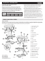 5
5
-
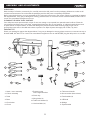 6
6
-
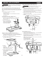 7
7
-
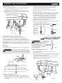 8
8
-
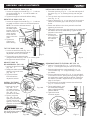 9
9
-
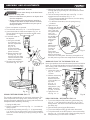 10
10
-
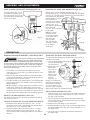 11
11
-
 12
12
-
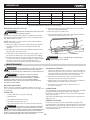 13
13
-
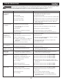 14
14
-
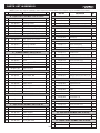 15
15
-
 16
16
-
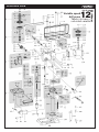 17
17
-
 18
18
-
 19
19
-
 20
20
-
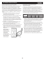 21
21
-
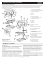 22
22
-
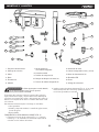 23
23
-
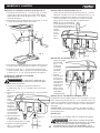 24
24
-
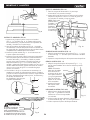 25
25
-
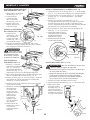 26
26
-
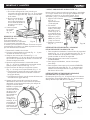 27
27
-
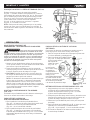 28
28
-
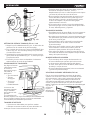 29
29
-
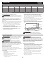 30
30
-
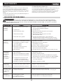 31
31
-
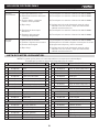 32
32
-
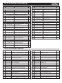 33
33
-
 34
34
-
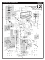 35
35
-
 36
36


KNOVA KN DP-3000N El manual del propietario
- Categoría
- Destornilladores eléctricos
- Tipo
- El manual del propietario
en otros idiomas
- English: KNOVA KN DP-3000N Owner's manual
Artículos relacionados
Otros documentos
-
Craftsman 124.34983 El manual del propietario
-
Craftsman 137229151 El manual del propietario
-
-
-
-
-
-
Hitachi Koki B 16RM Manual de usuario
-
-
Porter Cable PCB660DP Manual de usuario