STIEBEL ELTRON DHC 3-8 Operation Instruction
- Categoría
- Calentadores espaciales
- Tipo
- Operation Instruction

BEDIENUNG UND INSTALLATION
OPERATION AND INSTALLATION
UTILISATION ET INSTALLATION
OPERACIÓN E INSTALACIÓN
OBSŁUGA I INSTALACJA
Hydraulisch gesteuerter Kleindurchlauferhitzer | Hydraulically controlled small
instantaneous water heater | Petit chauffe-eau instantané à commande hydraulique|
Minicalentador de control hidráulico | Hydraulicznie sterowany mały ogrzewacz
przepływowy | Компактный проточный нагреватель с гидравлическим управлением |
» DHC 3
» DHC 4
» DHC 6
» DHC 8
» DHC 6 U

2 | DHC www.stiebel-eltron.com
INHALT | BESONDERE HINWEISE
BESONDERE HINWEISE
BEDIENUNG
1. Allgemeine Hinweise ����������������������������������������3
1.1 Sicherheitshinweise ��������������������������������������������� 3
1.2 Andere Markierungen in dieser Dokumentation ���������� 3
1.3 Maßeinheiten ����������������������������������������������������� 3
2. Sicherheit �����������������������������������������������������3
2.1 Bestimmungsgemäße Verwendung ������������������������� 3
2.2 Allgemeine Sicherheitshinweise ������������������������������ 3
2.3 Prüfzeichen ������������������������������������������������������� 4
3. Gerätebeschreibung �����������������������������������������4
4. Einstellungen �������������������������������������������������4
5. Reinigung, Pflege und Wartung ����������������������������4
6. Problembehebung �������������������������������������������4
INSTALLATION
7. Sicherheit �����������������������������������������������������5
7.1 Allgemeine Sicherheitshinweise ������������������������������ 5
7.2 Vorschriften, Normen und Bestimmungen ����������������� 5
8. Gerätebeschreibung �����������������������������������������5
8.1 Lieferumfang ����������������������������������������������������� 5
8.2 Zubehör ������������������������������������������������������������ 5
9. Vorbereitungen ����������������������������������������������� 5
9.1 Montageort ������������������������������������������������������� 5
9.2 Werkseinstellungen ��������������������������������������������� 6
10. Montage �������������������������������������������������������6
10.1 Montage-Alternativen nur für DHC 3, DHC 4, DHC6,
DHC 8 ��������������������������������������������������������������� 8
10.2 Montage abschließen ������������������������������������������� 9
11. Inbetriebnahme ����������������������������������������������9
11.1 Erstinbetriebnahme ��������������������������������������������� 9
11.2 Wiederinbetriebnahme ���������������������������������������� 10
12. Außerbetriebnahme ��������������������������������������� 10
13. Störungsbehebung ����������������������������������������� 10
14. Wartung ����������������������������������������������������� 10
15. Technische Daten ������������������������������������������� 11
15.1 Maße und Anschlüsse �����������������������������������������11
15.2 Elektroschaltplan ����������������������������������������������� 12
15.3 Temperaturerhöhung ������������������������������������������ 12
15.4 Einsatzbereiche �������������������������������������������������12
15.5 Angaben zum Energieverbrauch ����������������������������13
15.6 Datentabelle �����������������������������������������������������13
KUNDENDIENST UND GARANTIE
UMWELT UND RECYCLING
MONTAGESCHABLONE (IM MITTELTEIL DIESER ANLEITUNG)
BESONDERE HINWEISE
- Das Gerät kann von Kindern ab 8 Jahren sowie
von Personen mit verringerten physischen, sen-
sorischen oder mentalen Fähigkeiten oder Man-
gel an Erfahrung und Wissen benutzt werden,
wenn sie beaufsichtigt werden oder bezüglich
des sicheren Gebrauchs des Geräts unterwiesen
wurden und die daraus resultierenden Gefahren
verstanden haben. Kinder dürfen nicht mit dem
Gerät spielen. Reinigung und Benutzer-Wartung
dürfen nicht von Kindern ohne Beaufsichtigung
durchgeführt werden.
- Verbrühungsgefahr: Die Armatur kann eine Tem-
peratur von über 50°C annehmen.
- Das Gerät muss über eine Trennstrecke von min-
destens 3mm allpolig vom Netzanschluss ge-
trennt werden können.
- Befestigen Sie das Gerät wie in Kapitel „Installati-
on/ Montage“ beschrieben.
- Beachten Sie den maximal zulässigen Druck
(siehe Kapitel „Technische Daten/ Datentabelle).
- Entleeren Sie das Gerät wie in Kapitel „Installati-
on/ Wartung/ Gerät entleeren“ beschrieben.

BEDIENUNG
Allgemeine Hinweise
DEUTSCH
WWW.stiebel-eltron.com DHC | 3
BEDIENUNG
1. Allgemeine Hinweise
Die Kapitel „Besondere Hinweise“ und „Bedienung“ richten sich
an den Gerätebenutzer und den Fachhandwerker.
Das Kapitel „Installation“ richtet sich an den Fachhandwerker.
Hinweis
Lesen Sie diese Anleitung vor dem Gebrauch sorgfältig
durch und bewahren Sie sie auf.
Geben Sie die Anleitung ggf. an einen nachfolgenden
Benutzer weiter.
1.1 Sicherheitshinweise
1.1.1 Aufbau von Sicherheitshinweisen
!
SIGNALWORT Art der Gefahr
Hier stehen mögliche Folgen bei Nichtbeachtung des Si-
cherheitshinweises.
Hier stehen Maßnahmen zur Abwehr der Gefahr.
1.1.2 Symbole, Art der Gefahr
Symbol Art der Gefahr
Verletzung
Stromschlag
Verbrennung
(Verbrennung, Verbrühung)
1.1.3 Signalworte
SIGNALWORT Bedeutung
GEFAHR Hinweise, deren Nichtbeachtung schwere Verletzungen
oder Tod zur Folge haben.
WARNUNG Hinweise, deren Nichtbeachtung schwere Verletzungen
oder Tod zur Folge haben kann.
VORSICHT Hinweise, deren Nichtbeachtung zu mittelschweren oder
leichten Verletzungen führen kann.
1.2 Andere Markierungen in dieser Dokumentation
Hinweis
Allgemeine Hinweise werden mit dem nebenstehenden
Symbol gekennzeichnet.
Lesen Sie die Hinweistexte sorgfältig durch.
Symbol Bedeutung
Sachschaden
(Geräte-, Folge-, Umweltschaden)
Geräteentsorgung
Dieses Symbol zeigt Ihnen, dass Sie etwas tun müssen.
Die erforderlichen Handlungen werden Schritt für Schritt
beschrieben.
1.3 Maßeinheiten
Hinweis
Wenn nicht anders angegeben, sind alle Maße in Milli-
meter.
2. Sicherheit
2.1 Bestimmungsgemäße Verwendung
Das Gerät dient zur Erwärmung von Trinkwasser und kann ein
oder mehrere Entnahmestellen versorgen.
Das Gerät ist für den Einsatz im häuslichen Umfeld vorgesehen.
Es kann von nicht eingewiesenen Personen sicher bedient wer-
den. In nicht häuslicher Umgebung, z. B. im Kleingewerbe, kann
das Gerät ebenfalls verwendet werden, sofern die Benutzung in
gleicher Weise erfolgt.
Eine andere oder darüber hinausgehende Benutzung gilt als nicht
bestimmungsgemäß. Zum bestimmungsgemäßen Gebrauch ge-
hört auch das Beachten dieser Anleitung sowie der Anleitungen
für eingesetztes Zubehör.
2.2 Allgemeine Sicherheitshinweise
VORSICHT Verbrühung
Die Armatur kann während des Betriebs eine Temperatur
von über 50°C annehmen.
Bei Auslauftemperaturen größer 43°C besteht Verbrü-
hungsgefahr.
!
WARNUNG Verletzung
Das Gerät kann von Kindern ab 8 Jahren sowie von Per-
sonen mit verringerten physischen, sensorischen oder
mentalen Fähigkeiten oder Mangel an Erfahrung und
Wissen benutzt werden, wenn sie beaufsichtigt werden
oder bezüglich des sicheren Gebrauchs des Gerätes un-
terwiesen wurden und die daraus resultierenden Gefah-
ren verstanden haben. Kinder dürfen nicht mit dem Gerät
spielen. Reinigung und Benutzer-Wartung dürfen nicht
von Kindern ohne Beaufsichtigung durchgeführt werden.
!
Sachschaden
Das Gerät und die Armatur sind vom Nutzer vor Frost zu
schützen.
!
!

BEDIENUNG
Gerätebeschreibung
4 | DHC www.stiebel-eltron.com
2.3 Prüfzeichen
Siehe Typenschild am Gerät
3. Gerätebeschreibung
Der hydraulisch gesteuerte Klein-Durchlauferhitzer schaltet sich
über die hydraulische Steuerung automatisch ein.
Das Gerät erwärmt das Wasser direkt an der Entnahmestelle,
wenn es gebraucht wird. Durch kurze Leitungswege entstehen
geringe Energie- und Wasserverluste.
Die Warmwasserleistung hängt von der Kaltwassertemperatur,
der Heizleistung und der Durchflussmenge ab.
Das Rohrheizkörpersystem ist für kalkarme Wässer geeignet.
Das Gerät ist mit einem Überhitzungsschutz ausgestattet.
4. Einstellungen
Sobald Sie das Warmwasserventil an der Armatur öffnen, schaltet
automatisch das Heizsystem des Gerätes ein und das Wasser wird
erwärmt.
Einschaltmenge des Gerätes siehe Kapitel „Technische Daten“.
12
26�02�02�0229�
1 Power Leuchte
2 Overheating Leuchte
Hinweis
Bei Überhitzung des Gerätes leuchtet die Overheating
Leuchte.
Die Temperatur des Wassers können Sie mit der Armatur verän-
dern:
Temperatur erhöhen
Drosseln Sie die Durchflussmenge an der Armatur.
Temperatur verringern
Öffnen Sie die Armatur weiter oder mischen Sie mehr Kalt-
wasser bei.
Nach Unterbrechung der Wasserversorgung
siehe Kapitel „Inbetriebnahme/ Wiederinbetriebnahme“
5. Reinigung, Pflege und Wartung
Verwenden Sie keine scheuernden oder anlösenden Reini-
gungsmittel. Zur Pflege und Reinigung des Gerätes genügt
ein feuchtes Tuch.
Kontrollieren Sie regelmäßig die Armaturen. Kalk an den
Armaturausläufen können Sie mit handelsüblichen Entkal-
kungsmitteln entfernen.
Lassen Sie die elektrische Sicherheit am Gerät regelmäßig
von einem Fachhandwerker prüfen.
6. Problembehebung
Problem Ursache Behebung
Das Gerät schaltet trotz
voll geöffnetem Warm-
wasserventil nicht ein.
Am Gerät liegt keine
Netzspannung an.
Prüfen Sie die Sicherung
in der Hausinstallation.
Die Armatur oder der
Brausekopf ist verkalkt
oder verschmutzt.
Reinigen und / oder ent-
kalken Sie die Armatur /
Brausekopf.
Die Wasserversorgung
ist unterbrochen.
Entlüften Sie das Gerät
und die Kaltwasser-Zu-
laufleitung (siehe Kapitel
„Einstellungen“).
Es kommt kein warmes
Wasser, die Overheating
Leuchte leuchtet.
Das Gerät ist überhitzt,
die Heizleistung wurde
unterbrochen. Die ent-
nommene Wassermenge
ist zu gering.
Öffnen Sie weiter die
Armatur. Nach einer
Abkühlung schaltet das
Gerät automatisch wie-
der ein.
Können Sie die Ursache nicht beheben, rufen Sie den Fachhand-
werker. Zur besseren und schnelleren Hilfe teilen Sie ihm die
Nummer vom Typenschild mit (000000-0000-000000).
DHC. . .
Nr.: 000000-0000-000000

DEUTSCH
WWW.stiebel-eltron.com DHC | 5
INSTALLATION
Sicherheit
INSTALLATION
7. Sicherheit
Die Installation, Inbetriebnahme sowie Wartung und Reparatur
des Gerätes darf nur von einem Fachhandwerker durchgeführt
werden.
7.1 Allgemeine Sicherheitshinweise
Wir gewährleisten eine einwandfreie Funktion und Betriebssicher-
heit nur, wenn das für das Gerät bestimmte Original-Zubehör und
die originalen Ersatzteile verwendet werden.
!
Sachschaden
Beachten Sie die maximale Zulauftemperatur. Bei höhe-
ren Temperaturen kann das Gerät beschädigt werden.
7.2 Vorschriften, Normen und Bestimmungen
Hinweis
Beachten Sie alle nationalen und regionalen Vorschriften
und Bestimmungen.
Härtebereich des Wassers
Der Härtebereich des Wassers darf nicht größer sein als in den
„Technische Daten / Datentabelle“ angegeben.
8. Gerätebeschreibung
8.1 Lieferumfang
Mit dem Gerät werden geliefert:
- Kabelabdichtung
- Anschlussstutzen
- Flachdichtungen
- 2 Befestigungsschrauben 4 x 35 und Dübel
- Unterlegscheibe
- Montageschablone im Mittelteil dieser Anleitung
- montierte Anschlussrohre (nur bei DHC 6 U)
- 2 Sechskantschrauben (nur bei DHC 6 U)
8.2 Zubehör
Druckfeste Armaturen
- WKMD Zweigriff-Küchenwandarmatur
- WBMD Zweigriff-Badewandarmatur
9. Vorbereitungen
Spülen Sie die Wasserleitung gut durch.
Wasserinstallation
- Ein Sicherheitsventil ist nicht erforderlich.
- Volumenstrom
Stellen Sie sicher, dass der Volumenstrom (siehe Kapitel
„Technische Daten / Datentabelle“, Ein) zum Einschalten des
Gerätes erreicht wird.
Erhöhen Sie den Wasserleitungsdruck, falls der benötigte
Volumenstrom bei voll geöffnetem Entnahmeventil nicht er-
reicht wird.
!
Sachschaden
Eine Rohrbegleitheizung ist nicht zulässig.
Zugelassene Werkstoffe der Wasserleitungen
- Kaltwasser-Zulaufleitung:
feuerverzinktes Stahlrohr, Edelstahlrohr, Kupferrohr oder
Kunststoffrohr
- Warmwasser-Auslaufleitung:
Edelstahlrohr oder Kupferrohr
!
Sachschaden
Kunststoff-Rohrsysteme für die Warmwasserleitung sind
nicht zugelassen.
Armaturen
Verwenden Sie geeignete Armaturen (siehe Kapitel „Gerätebe-
schreibung / Zubehör“). Offene Armaturen sind nicht zulässig.
9.1 Montageort
!
Sachschaden
Die Installation des Gerätes darf nur im frostfreien Raum
erfolgen.
Montieren Sie das Gerät senkrecht und in der Nähe der
Entnahmestelle.

6 | DHC www.stiebel-eltron.com
INSTALLATION
Montage
Übertischmontage DHC 3, DHC 4, DHC 6, DHC 8
26�02�02�0241�
1 2
1 Aufputzinstallation
2 Unterputz-Installation
Untertischmontage DHC 6 U
26�02�02�0239
9.2 Werkseinstellungen
Die Geräte sind im Lieferzustand vorbereitet:
DHC 3, DHC 4, DHC 6, DHC 8
- Elektroanschluss oben, Unterputz-Installation
- Wasseranschluss Unterputz-Installation
DHC 6 U
- Elektroanschluss unten, Aufputz-Installation
- Wasseranschluss Aufputz-Installation
10. Montage
Hinweis
Montieren Sie das Gerät an die Wand. Die Wand
muss ausreichend tragfähig sein.
In diesem Kapitel werden Montagen entsprechend der Werksein-
stellungen beschrieben.
Weitere Montagemöglichkeiten für die Geräte DHC 3, DHC 4, DHC6
und DHC 8 siehe Kapitel „Montage-Alternativen“.
26�02�02�1105�
Lösen Sie die Kappenbefestigungsschraube mit zwei
Umdrehungen.
Nehmen Sie die Gerätevorderkappe nach vorne ab.
26�02�02�1113�
1
2
DHC 3, DHC 4,
DHC 6, DHC 8
1 Elektroanschluss oben
2 Wasseranschluss Unterputz
Schneiden oder brechen Sie die benötigten Durchführungen
in der Geräterückwand sauber heraus. Benutzen Sie gegebe-
nenfalls eine Feile.

DEUTSCH
WWW.stiebel-eltron.com DHC | 7
INSTALLATION
Montage
D0000033915
DHC 6 U
1
1 Elektroanschluss unten
4,5 - 5,5
4 x 35
6,0
6,0
26�02�02�0245�
Zeichnen Sie die Bohrlöcher mit der Montageschablone an.
Bohren Sie die Löcher und setzen Sie passenden Dübel ein.
Hinweis: Bei Austausch eines DHC-Gerätes können die Bohrlöcher
verwendet werden. Benutzen Sie für die obere Bohrung die bei-
gefügte große Unterlegscheibe.
Schrauben Sie die beiden Befestigungsschrauben bis zur Ein-
tauchtiefe ein.
DHC 3, DHC 4,
DHC 6, DHC 8
50
115
26�02�02�0252�
Richten Sie das elektrische Anschlusskabel her.
46 - 50
26�02�02�0242�
DHC 3, DHC 4,
DHC 6, DHC 8
Schrauben Sie die beiden Anschlussstutzen ein. Beachten Sie
die Einschraubtiefe.
D0000033916
DHC 3,
DHC 4,
DHC 6,
DHC 8
Schneiden Sie entsprechend des gewählten elektrischen An-
schlusskabels eine Öffnung in die Kabelabdichtung.
Montieren Sie die Kabelabdichtung in die Rückwand.
Führen Sie das elektrische Anschlusskabel durch die
Geräterückwand.
D0000033917
DHC 3, DHC 4,
DHC 6, DHC 8
DHC 6 U
Montieren Sie die Geräterückwand über die Schrauben und
schieben Sie die Geräterückwand nach unten.

8 | DHC www.stiebel-eltron.com
INSTALLATION
Montage
DHC 3, DHC 4, DHC 6, DHC 8: Verschrauben Sie die An-
schlussrohre mit den beiliegenden Flachdichtungen auf die
Anschlussstutzen.
Richten Sie das Gerät aus und ziehen Sie die Befestigungs-
schrauben fest.
Elektroanschluss herstellen
Warnung Stromschlagg
Führen Sie alle elektrischen Anschluss- und Installations-
arbeiten nach Vorschrift aus.
Warnung Stromschlag
Achten Sie darauf, dass das Gerät an den Schutzlei-
ter angeschlossen ist.
Der Anschluss an das Stromnetz ist nur als fester An-
schluss in Verbindung mit der herausnehmbaren Kabel-
tülle erlaubt. Das Gerät muss über eine Trennstrecke von
mindestens 3mm allpolig vom Netzanschluss getrennt
werden können.
!
Sachschaden
Beachten Sie das Typenschild. Die angegebene Spannung
muss mit der Netzspannung übereinstimmen.
Schließen Sie das elektrische Anschlusskabel an die Netz-
anschlussklemme an (siehe Kapitel „Technische Daten /
Elektroschaltplan“).
10.1 Montage-Alternativen nur für DHC 3, DHC 4,
DHC6, DHC 8
- Elektroanschluss Aufputz oben
- Elektroanschluss Aufputz unten
- Wasserinstallation Aufputz
Schneiden oder brechen Sie die benötigte Durchführung in
der Rückwand sauber heraus, Positionen siehe Kapitel „Tech-
nische Daten / Maße und Anschlüsse“. Benutzen Sie gegebe-
nenfalls eine Feile.
Elektroanschluss Aufputz oben
Schneiden Sie entsprechend des gewählten elektrischen An-
schlusskabels eine Öffnung in die Kabelabdichtung (Positio-
nen der Anschlüsse siehe Kapitel „Technische Daten“).
Montieren Sie die Kabelabdichtung in die Rückwand.
Führen Sie das elektrische Anschlusskabel durch die
Geräterückwand.
Elektroanschluss Aufputz unten
26�02�02�1110�
DHC 3, DHC 4,
DHC 6, DHC 8
Drücken Sie den Rasthaken zur Befestigung der Netzan-
schlussklemme herunter und ziehen Sie diese heraus.
Versetzen Sie die Netzanschlussklemme im Gerät von oben
nach unten und befestigen Sie die Netzanschlussklemme,
indem Sie sie unter den Rasthaken schieben.
Hinweis
Die Schaltlitzen dürfen den Differenzdruckschalter nicht
beeinträchtigen.
Verlegen Sie die Schaltlitzen seitlich zwischen dem
Druckdifferenzschalter und der Geräterückwand.
Schneiden Sie entsprechend des gewählten elektrischen An-
schlusskabels eine Öffnung in die Kabelabdichtung.
Montieren Sie die Kabelabdichtung in die Rückwand.
Führen Sie das elektrische Anschlusskabel durch die
Geräterückwand.

DEUTSCH
WWW.stiebel-eltron.com DHC | 9
INSTALLATION
Inbetriebnahme
Wasserinstallation Aufputz
26�02�02�1341
DHC 3, DHC 4,
DHC 6, DHC 8
Schneiden oder brechen Sie die benötigten Durchführungen
in der Geräterückwand sauber heraus. Benutzen Sie gegebe-
nenfalls eine Feile.
DHC 3, DHC 4,
DHC 6, DHC 8
26�02�02�1108�
Führen Sie die Anschlussstutzen durch die Öffnungen der Ge-
räterückwand und montieren Sie sie mit Flachdichtungen an
die Anschlussrohre des Gerätes.
Montieren Sie die Anschlussrohre der Armatur mit Flachdich-
tungen an die Anschlussstutzen.
10.2 Montage abschließen
26�02�02�1106�
Montieren Sie die Gerätkappe.
Befestigen Sie die Gerätekappe mit der Schraube.
Alternative Kappenbefestigung nur bei DHC 6 U
Bei geringem Abstand zwischen Gerät und Fußboden können
Sie die beigefügten Sechskantschrauben zur Kappenbefestigung
verwenden.
26�02�02�0256
3
2
1
DHC 6 U
1 Standard Befestigungsschraube
2 Sechskantschrauben
3 Ausbruchmarkierungen
Entfernen Sie die Standardschraube.
Schrauben Sie die Sechskantschrauben ein.
Brechen oder schneiden Sie die Durchführungen in der Ge-
rätekappe sauber heraus. Benutzen Sie gegebenenfalls eine
Feile.
11. Inbetriebnahme
Warnung Stromschlag
Die Inbetriebnahme darf nur durch einen Fachhand-
werker unter der Beachtung der Sicherheitsvorschriften
erfolgen.
11.1 Erstinbetriebnahme
26�02�05�0087
Öffnen und schließen Sie mehrfach alle angeschlossenen
Entnahmeventile, bis das Leitungsnetz und das Gerät luftfrei
sind.
Führen Sie eine Dichtheitskontrolle durch.
Schalten Sie die Netzspannung ein.
Stellen Sie gegebenenfalls die Durchflussmenge so ein, so-
dass die Auslauftemperatur ca. 35 - 40°C beträgt.
Prüfen Sie die Arbeitsweise des Gerätes.
Übergabe des Gerätes
Erklären Sie dem Benutzer die Funktion des Gerätes und ma-
chen Sie ihn mit dem Gebrauch des Gerätes vertraut.
Weisen Sie den Benutzer auf mögliche Gefahren hin, speziell
die Verbrühungsgefahr.
Übergeben Sie diese Anleitung.

10 | DHC www.stiebel-eltron.com
INSTALLATION
Außerbetriebnahme
11.2 Wiederinbetriebnahme
!
Sachschaden
Nach Unterbrechung der Wasserversorgung muss das
Gerät mit folgenden Schritten wieder in Betrieb genom-
men werden, damit das Heizsystem nicht zerstört wird.
Schalten Sie das Gerät spannungsfrei, indem Sie die
Sicherung ausschalten.
Öffnen Sie die Armatur eine Minute lang, bis das
Gerät und die vorgeschaltete Kaltwasser-Zulauflei-
tung luftfrei sind.
Schalten Sie die Netzspannung wieder ein.
- siehe Kapitel „Erstinbetriebnahme“
12. Außerbetriebnahme
Trennen Sie das Gerät allpolig vom Netzanschluss.
Entleeren Sie das Gerät (siehe Kapitel „Wartung“).
13. Störungsbehebung
Problem Ursache Behebung
Der Differenzdruckschal-
ter schaltet die Heizkör-
per trotz voll geöffnetem
Warmwasserventil nicht
ein.
Das Sieb im Differenz-
druckschalter ist ver-
stopft.
Reinigen Sie das Sieb im
Differenzdruckschalter.
Die Durchflussmenge ist
zu gering.
Korrigieren Sie die
Durchflussmenge, siehe
Kapitel „Wartung“.
Es kommt kein Warm-
wasser trotz hörbaren
Einschaltens des Diffe-
renzdruckschalters.
Der Sicherheits-Tempe-
raturbegrenzer hat aus
Sicherheitsgründen das
Gerät ausgeschaltet.
Beheben Sie die Fehle-
rursache. Machen Sie
das Gerät spannungsfrei
und entlasten Sie den
Wasserleitungsdruck.
Drücken Sie den Sicher-
heits-Temperaturbegren-
zer wieder ein, siehe
Kapitel „Wartung“.
Das Heizsystem ist
verkalkt, der Sicher-
heits-Temperaturbe-
grenzer hat wegen Wär-
mestau ausgeschaltet.
Erneuern Sie das Heiz-
system.
Das Heizsystem ist de-
fekt.
Erneuern Sie das Heiz-
system.
14. Wartung
Warnung Stromschlag
Trennen Sie bei allen Arbeiten das Gerät allpolig vom
Netzanschluss!
Gerät entleeren
Das Gerät können Sie für Wartungsarbeiten oder zum Schutz vor
Frost entleeren.
GEFAHR Verbrühung
Beim Entleeren des Gerätes kann heißes Wasser aus-
treten.
Schließen Sie das Absperrventil in der
Kaltwasser-Zulaufleitung.
Öffnen Sie die alle Entnahmeventile.
Lösen Sie den Elektroanschluss.
Lösen Sie die Wasseranschlüsse vom Gerät.
Durchflussmenge einstellen
Falls die gewünschte Temperatur nicht erreicht wird, können Sie
die Durchflussmenge begrenzen. Somit erhalten Sie eine höhere
Temperatur.
26�02�02�0255�
Stellen Sie die Durchflussmenge mittels der Justierschraube
so ein, dass die Auslauftemperatur dem Kapitel „Technische
Daten / Datentabelle“ übereinstimmt.
Sieb reinigen
Das eingebaute Sieb können Sie nach Demontage des Kaltwasse-
ranschlussrohres reinigen.
1.
2.
90°
26�02�02�0258�
1
2
3
1 Erdungsschraube
2 Sieb
3 Kaltwasseranschlussrohr
Lösen Sie die Erdungsschraube ca. zwei Umdrehungen.
Lösen Sie das Kaltwasseranschlussrohr, indem Sie das Rohr
im Differenzdruckschalter um 90° drehen und nach unten
ziehen.
Reinigen ggf. erneuern Sie das Sieb.
Montieren Sie die Bauteile in umgekehrter Reihenfolge.
!
Sachschaden
Befestigen Sie unbedingt die Erdungsschraube.

DEUTSCH
WWW.stiebel-eltron.com DHC | 11
INSTALLATION
Technische Daten
Sicherheits-Temperaturbegrenzer aktivieren
Nachdem der mögliche Fehler behoben wurde, können Sie den
Sicherheits-Temperaturbegrenzer wieder aktivieren.
26�02�02�0261�
Machen Sie das Gerät spannungsfrei und entlasten Sie den
Wasserleitungsdruck. Drücken Sie den Sicherheits-Tempera-
turbegrenzer wieder ein.
Lagerung des Gerätes
Lagern Sie ein demontiertes Gerät frostfrei, da sich Restwas-
ser im Gerät befindet, das gefrieren und Schäden verursa-
chen kann.
15. Technische Daten
15.1 Maße und Anschlüsse
DHC 3, DHC 4, DHC 6, DHC 8
360
200
c06 c01
100
104
35
273
59
54
242
c01
c06
9
b02
D0000018085
b02 Durchführung elektr. Leitungen 1
c01 Kaltwasser Zulauf Außengewinde G 1/2 A
c06 Warmwasser Auslauf Außengewinde G 1/2 A
Alternative Anschlussmöglichkeiten DHC 3, DHC 4, DHC 6, DHC8
b03b02b03
270
b04
54
242
D0000019209
b02 Durchführung elektr. Leitungen 1
c01 Kaltwasser Zulauf Außengewinde G 1/2 A
c06 Warmwasser Auslauf Außengewinde G 1/2 A
DHC 6 U
360
385
200
104
c06 c01
100 26
c01
c06
b01
273
65
D0000033947
b01 Durchführung elektr. Leitungen
c01 Kaltwasser Zulauf Außengewinde G 3/8 A
c06 Warmwasser Auslauf Außengewinde G 3/8 A

12 | DHC www.stiebel-eltron.com
INSTALLATION
Technische Daten
15.2 Elektroschaltplan
DHC 3, DHC 4
1/N/PE ~ 220 ... 240 V
85�02�03�0006
DHC 6, DHC 8, DHC 6 U
1/N/PE ~ 220 ... 240 V
85�02�03�0007
15.3 Temperaturerhöhung
Folgende Temperaturerhöhungen des Gerätes ergeben sich bei
einer Netzspannung von 230V:
1 2 3 4 5 6 7 8 9 10
0
5
10
15
20
25
30
35
40
45
50
4
3
2
1
84�02�02�0025�
x Durchflussmenge in l/min
Y Temperaturerhöhung in K
1 3,0kW
2 4,4kW
3 6,6kW
4 8,8kW
Beispiel DHC 4 mit 4,4 kW
Durchflussmenge 2,5 l/min
Temperaturerhöhung 25 K
Kaltwasserzulauftemperatur 10 °C
Auslauftemperatur 35 °C
15.4 Einsatzbereiche
Siehe Kapitel „Datentabelle“.

DEUTSCH
WWW.stiebel-eltron.com DHC | 13
INSTALLATION
Technische Daten
15.5 Angaben zum Energieverbrauch
Die Produktdaten entsprechen den EU-Verordnungen zur Richtli-
nie für umweltgerechte Gestaltung energieverbrauchsrelevanter
Produkte (ErP).
DHC 3 DHC 4 DHC 6 DHC 8 DHC 6 U
073478 073715 073480 073481 073479
Hersteller STIEBEL ELTRON STIEBEL ELTRON STIEBEL ELTRON STIEBEL ELTRON STIEBEL ELTRON
Lastprofil XXS XXS XXS XS XXS
Energieeffizienzklasse A A A A A
Jährlicher Stromverbrauch kWh 505 505 522 477 522
Energetischer Wirkungsgrad % 37 37 36 39 36
Schallleistungspegel dB(A) 15 15 15 15 15
Besondere Hinweise zur Effizienz-
messung
keine keine keine keine keine
15.6 Datentabelle
DHC 3 DHC 4 DHC 6 DHC 8 DHC 6 U
073478 073715 073480 073481 073479
Elektrische Daten
Nennspannung V 220 230 240 220 230 240 220 230 240 220 230 240 220 230 240
Nennleistung kW 2,7 3,0 3,3 4,0 4,4 4,8 6,0 6,6 7,2 8,0 8,8 9,6 6,0 6,6 7,2
Nennstrom A 12,2 13,0 13,4 18,1 19,1 20,8 27,2 28,6 30,0 36,3 38,2 40,0 27,2 28,6 30,0
Absicherung A 16 16 16 20 20 20 30 30 30 40 40 40 30 30 30
Leitungsquerschnitt mm
2
2,5 4 6 4
Phasen 1/N/PE 1/N/PE 1/N/PE 1/N/PE 1/N/PE
Frequenz Hz 50/60 50/60 50/60 50/60 50/60
Max. Netzimpedanz Zmax nach DIN EN
61000-3-11
Ω 0,47 0,47 0,32 0,24 0,32
Anschlüsse
Wasseranschluss G 1/2 A G 1/2 A G 1/2 A G 1/2 A G 3/8 A
Summe Erdalkalien mol/m³ 2,5 2,5 2,5 2,5 2,6
Gesamthärte (H
2
O) Grad d 14 14 14 14 14
Härtebereich 2 (mittelhart) 2 (mittelhart) 2 (mittelhart) 2 (mittelhart) 2 (mittelhart)
Einsatzgrenzen
Max. zulässiger Druck MPa 1 1 1 1 1
Prüfdruck MPa 1,1 1,1 1,1 1,1
Werte
Max. zulässige Zulauftemperatur °C 30 20 30 25 30
Ein l/min > 1,6 > 1,6 > 2,6 > 3,0 > 2,6
Druckverlust bei Volumenstrom MPa 0,025 0,025 0,025 0,03 0,025
Volumenstrom für Druckverlust l/min 1,6 1,6 2,6 3,0 2,6
Warmwasserdarbietung l/min 1,7 2,5 3,7 5,0 3,7
Δϑ bei Darbietung K 25 25 25 25 25
Hydraulische Daten
Nenninhalt l 0,5 0,5 0,5 0,5 0,5
Ausführungen
Bauart geschlossen X X X X X
Montageart Übertisch X X X X
Montageart Untertisch X
Schutzart (IP) IP24 IP24 IP24 IP24 IP24
Schutzklasse 1 1 1 1 1
Werkstoff des Druckbehälters Kupfer Kupfer Kupfer Kupfer Kupfer
Heizsystem Wärmeerzeuger Rohrheizkörper Rohrheizkörper Rohrheizkörper Rohrheizkörper Rohrheizkörper
Kappe und Rückwand Kunststoff Kunststoff Kunststoff Kunststoff Kunststoff
Farbe weiß weiß weiß weiß weiß
Dimensionen
Höhe mm 360 360 360 360 360
Breite mm 200 200 200 200 200
Tiefe mm 104 104 104 104 104
Gewichte
Gewicht kg 2 2,1 2,4 2,4 2,4

14 | DHC www.stiebel-eltron.com
KUNDENDIENST UND GARANTIE
Erreichbarkeit
Sollte einmal eine Störung an einem unserer Produkte auftre-
ten, stehen wir Ihnen natürlich mit Rat und Tat zur Seite.
Rufen Sie uns an:
05531 702-111
oder schreiben Sie uns:
Stiebel Eltron GmbH & Co. KG
- Kundendienst -
Fürstenberger Straße 77, 37603 Holzminden
E-Mail: kundendienst@stiebel-eltron.de
Fax: 05531 702-95890
Weitere Anschriften sind auf der letzten Seite aufgeführt.
Unseren Kundendienst erreichen Sie telefonisch rund um die
Uhr, auch an Samstagen und Sonntagen sowie an Feiertagen.
Kundendiensteinsätze erfolgen während unserer Geschäftszei-
ten (von 7.15 bis 18.00 Uhr, freitags bis 17.00 Uhr). Als Sonder-
service bieten wir Kundendiensteinsätze bis 21.30 Uhr. Für die-
sen Sonderservice sowie Kundendiensteinsätze an Wochenen-
den und Feiertagen werden höhere Preise berechnet.
Garantiebedingungen
Diese Garantiebedingungen regeln zusätzliche Garantieleistun-
gen von uns gegenüber dem Endkunden. Sie treten neben die
gesetzlichen Gewährleistungsansprüche des Kunden. Die ge-
setzlichen Gewährleistungsansprüche gegenüber den sonsti-
gen Vertragspartnern sind nicht berührt.
Diese Garantiebedingungen gelten nur für solche Geräte, die
vom Endkunden in der Bundesrepublik Deutschland als Neuge-
räte erworben werden. Ein Garantievertrag kommt nicht zu-
stande, soweit der Endkunde ein gebrauchtes Gerät oder ein
neues Gerät seinerseits von einem anderen Endkunden erwirbt.
Inhalt und Umfang der Garantie
Die Garantieleistung wird erbracht, wenn an unseren Geräten
ein Herstellungs- und/oder Materialfehler innerhalb der Garan-
tiedauer auftritt. Die Garantie umfasst jedoch keine Leistungen
für solche Geräte, an denen Fehler, Schäden oder Mängel auf-
grund von Verkalkung, chemischer oder elektrochemischer
Einwirkung, fehlerhafter Aufstellung bzw. Installation sowie
unsachgemäßer Einregulierung, Bedienung oder unsachgemä-
ßer Inanspruchnahme bzw. Verwendung auftreten. Ebenso
ausgeschlossen sind Leistungen aufgrund mangelhafter oder
unterlassener Wartung, Witterungseinflüssen oder sonstigen
Naturerscheinungen.
Die Garantie erlischt, wenn am Gerät Reparaturen, Eingriffe oder
Abänderungen durch nicht von uns autorisierte Personen vor-
genommen wurden.
Die Garantieleistung umfasst die sorgfältige Prüfung des Gerä-
tes, wobei zunächst ermittelt wird, ob ein Garantieanspruch
besteht. Im Garantiefall entscheiden allein wir, auf welche Art
der Fehler behoben wird. Es steht uns frei, eine Reparatur des
Gerätes ausführen zu lassen oder selbst auszuführen. Etwaige
ausgewechselte Teile werden unser Eigentum.
Für die Dauer und Reichweite der Garantie übernehmen wir
sämtliche Material- und Montagekosten.
Soweit der Kunde wegen des Garantiefalles aufgrund gesetzli-
cher Gewährleistungsansprüche gegen andere Vertragspartner
Leistungen erhalten hat, entfällt eine Leistungspflicht von uns.
Soweit eine Garantieleistung erbracht wird, übernehmen wir
keine Haftung für die Beschädigung eines Gerätes durch Dieb-
stahl, Feuer, Aufruhr oder ähnliche Ursachen.
Über die vorstehend zugesagten Garantieleistungen hinausge-
hend kann der Endkunde nach dieser Garantie keine Ansprüche
wegen mittelbarer Schäden oder Folgeschäden, die durch das
Gerät verursacht werden, insbesondere auf Ersatz außerhalb des
Gerätes entstandener Schäden, geltend machen. Gesetzliche
Ansprüche des Kunden uns gegenüber oder gegenüber Dritten
bleiben unberührt.
Garantiedauer
Für im privaten Haushalt eingesetzte Geräte beträgt die Garan-
tiedauer 24 Monate; im Übrigen (zum Beispiel bei einem Einsatz
der Geräte in Gewerbe-, Handwerks- oder Industriebetrieben)
beträgt die Garantiedauer 12 Monate.
Die Garantiedauer beginnt für jedes Gerät mit der Übergabe des
Gerätes an den Kunden, der das Gerät zum ersten Mal einsetzt.
Garantieleistungen führen nicht zu einer Verlängerung der
Garantiedauer. Durch die erbrachte Garantieleistung wird keine
neue Garantiedauer in Gang gesetzt. Dies gilt für alle erbrachten
Garantieleistungen, insbesondere für etwaig eingebaute Ersatz-
teile oder für die Ersatzlieferung eines neuen Gerätes.
Inanspruchnahme der Garantie
Garantieansprüche sind vor Ablauf der Garantiedauer, innerhalb
von zwei Wochen, nachdem der Mangel erkannt wurde, bei uns
anzumelden. Dabei müssen Angaben zum Fehler, zum Gerät
und zum Zeitpunkt der Feststellung gemacht werden. Als Ga-
rantienachweis ist die Rechnung oder ein sonstiger datierter
Kaufnachweis beizufügen. Fehlen die vorgenannten Angaben
oder Unterlagen, besteht kein Garantieanspruch.
Garantie für in Deutschland erworbene, jedoch außer-
halb Deutschlands eingesetzte Geräte
Wir sind nicht verpflichtet, Garantieleistungen außerhalb der
Bundesrepublik Deutschland zu erbringen. Bei Störungen eines
im Ausland eingesetzten Gerätes ist dieses gegebenenfalls auf
Gefahr und Kosten des Kunden an den Kundendienst in
Deutschland zu senden. Die Rücksendung erfolgt ebenfalls auf
Gefahr und Kosten des Kunden. Etwaige gesetzliche Ansprüche
des Kunden uns gegenüber oder gegenüber Dritten bleiben
auch in diesem Fall unberührt.
Außerhalb Deutschlands erworbene Geräte
Für außerhalb Deutschlands erworbene Geräte gilt diese Garan-
tie nicht. Es gelten die jeweiligen gesetzlichen Vorschriften und
gegebenenfalls die Lieferbedingungen der Ländergesellschaft
bzw. des Importeurs.
KUNDENDIENST UND GARANTIE

DEUTSCH
WWW.stiebel-eltron.com DHC | 15
UMWELT UND RECYCLING
Entsorgung von Transport- und
Verkaufsverpackungsmaterial
Damit Ihr Gerät unbeschädigt bei Ihnen ankommt, haben wir
es sorgfältig verpackt. Bitte helfen Sie, die Umwelt zu schützen,
und entsorgen Sie das Verpackungsmaterial des Gerätes sach-
gerecht. Wir beteiligen uns gemeinsam mit dem Großhandel
und dem Fachhandwerk/ Fachhandel in Deutschland an einem
wirksamen Rücknahme- und Entsorgungskonzept für die um-
weltschonende Aufarbeitung der Verpackungen.
Überlassen Sie die Transportverpackung dem Fachhandwerker
beziehungsweise dem Fachhandel.
Entsorgen Sie Verkaufsverpackungen über eines der Dualen
Systeme in Deutschland.
Entsorgung von Altgeräten in Deutschland
Geräteentsorgung
Die mit diesem Symbol gekennzeichneten Geräte dür-
fen nicht mit dem Hausmüll entsorgt werden.
Als Hersteller sorgen wir im Rahmen der Produktverantwor-
tung für eine umweltgerechte Behandlung und Verwertung
der Altgeräte. Weitere Informationen zur Sammlung und Ent-
sorgung erhalten Sie über Ihre Kommune oder Ihren Fach-
handwerker/ Fachhändler.
Bereits bei der Entwicklung neuer Geräte achten wir auf eine
hohe Recyclingfähigkeit der Materialien.
Über das Rücknahmesystem werden hohe Recyclingquoten
der Materialien erreicht, um Deponien und die Umwelt zu ent-
lasten. Damit leisten wir gemeinsam einen wichtigen Beitrag
zum Umweltschutz.
Entsorgung außerhalb Deutschlands
Entsorgen Sie dieses Gerät fach- und sachgerecht nach den
örtlich geltenden Vorschriften und Gesetzen.
UMWELT UND RECYCLING
MONTAGESCHABLONE (IM MITTELTEIL DIESER ANLEITUNG)

16 | DHC www.stiebel-eltron.com
CONTENTS | SPECIAL INFORMATION
SPECIAL INFORMATION
OPERATION
1. General information ��������������������������������������� 17
1.1 Safety instructions ���������������������������������������������� 17
1.2 Other symbols in this documentation ���������������������� 17
1.3 Units of measurement ����������������������������������������� 17
2. Safety �������������������������������������������������������� 17
2.1 Intended use ����������������������������������������������������� 17
2.2 General safety instructions ����������������������������������� 17
2.3 Test symbols ����������������������������������������������������� 17
3. Appliance description ������������������������������������� 18
4. Settings ����������������������������������������������������� 18
5. Cleaning, care and maintenance ������������������������� 18
6. Troubleshooting �������������������������������������������� 18
INSTALLATION
7. Safety �������������������������������������������������������� 19
7.1 General safety instructions ����������������������������������� 19
7.2 Instructions, standards and regulations ������������������� 19
8. Appliance description ������������������������������������� 19
8.1 Standard delivery ����������������������������������������������� 19
8.2 Accessories ������������������������������������������������������� 19
9. Preparations ������������������������������������������������ 19
9.1 Installation site �������������������������������������������������� 19
9.2 Factory settings �������������������������������������������������20
10. Installation �������������������������������������������������� 20
10.1 Alternative installation options only for DHC 3, DHC 4,
DHC6, DHC 8 ���������������������������������������������������� 21
10.2 Completing the installation ����������������������������������� 22
11. Commissioning ��������������������������������������������� 23
11.1 Commissioning �������������������������������������������������� 23
11.2 Recommissioning ����������������������������������������������� 23
12. Shutting down ���������������������������������������������� 23
13. Troubleshooting �������������������������������������������� 23
14. Maintenance ������������������������������������������������ 23
15. Specification ������������������������������������������������ 24
15.1 Dimensions and connections ��������������������������������� 24
15.2 Wiring diagram ������������������������������������������������� 25
15.3 Increasing the temperature ����������������������������������� 25
15.4 Application areas �����������������������������������������������26
15.5 Details on energy consumption ������������������������������ 26
15.6 Data table �������������������������������������������������������� 27
GUARANTEE
ENVIRONMENT AND RECYCLING
INSTALLATION TEMPLATE (IN THE CENTRE SECTION OF THESE
INSTRUCTIONS)
SPECIAL INFORMATION
- The appliance may be used by children aged 8
and up and persons with reduced physical, sen-
sory or mental capabilities or a lack of experience
and know-how, provided that they are supervised
or they have been instructed on how to use the
appliance safely and have understood the result-
ing risks. Children must never play with the ap-
pliance. Children must never clean the appliance
or perform user maintenance unless they are
supervised.
- Risk of scalding: The tap can reach temperatures
in excess of 60°C.
- Ensure the appliance can be separated from the
power supply by an isolator that disconnects all
poles with at least 3mm contact separation.
- Secure the appliance as described in chapter “In-
stallation/ Installation”.
- Observe the maximum permissible pressure (see
chapter “Specification/ Data table”).
- Drain the appliance as described in chap-
ter “Installation/ Maintenance/ Draining the
appliance”.

OPERATION
General information
WWW.stiebel-eltron.com DHC | 17
ENGLISH
OPERATION
1. General information
The chapters “Special Information” and “Operation” are intended
for both the user and qualified contractors.
The chapter “Installation” is intended for qualified contractors.
Note
Read these instructions carefully before using the appli-
ance and retain them for future reference.
Pass on the instructions to a new user if required.
1.1 Safety instructions
1.1.1 Structure of safety instructions
!
KEYWORD Type of risk
Here, possible consequences are listed that may result
from failure to observe the safety instructions.
Steps to prevent the risk are listed.
1.1.2 Symbols, type of risk
Symbol Type of risk
Injury
Electrocution
Burns
(burns, scalding)
1.1.3 Keywords
KEYWORD Meaning
DANGER Failure to observe this information will result in serious
injury or death.
WARNING Failure to observe this information may result in serious
injury or death.
CAUTION Failure to observe this information may result in non-seri-
ous or minor injury.
1.2 Other symbols in this documentation
Note
General information is identified by the adjacent symbol.
Read these texts carefully.
Symbol Meaning
Material losses
(appliance damage, consequential losses and environmen-
tal pollution)
Appliance disposal
This symbol indicates that you have to do something. The ac-
tion you need to take is described step by step.
1.3 Units of measurement
Note
All measurements are given in mm unless stated oth-
erwise.
2. Safety
2.1 Intended use
The appliance is intended for heating domestic hot water and can
supply one or several draw-off points.
This appliance is intended for domestic use. It can be used safely
by untrained persons. The appliance can also be used in a non-do-
mestic environment, e.g. in a small business, as long as it is used
in the same way.
Any other use beyond that described shall be deemed inappropri-
ate. Observation of these instructions and of instructions for any
accessories used is also part of the correct use of this appliance.
2.2 General safety instructions
CAUTION Scalding
During operation, the tap can reach temperatures in ex-
cess of 50 °C.
There is a risk of scalding at outlet temperatures in ex-
cess of 43 °C.
!
WARNING Injury
The appliance may be used by children aged 8 and older
and persons with reduced physical, sensory or mental
capabilities or a lack of experience and know-how, pro-
vided that they are supervised or they have been in-
structed on how to use the appliance safely and have
understood the resulting risks. Children must never play
with the appliance. Children must never clean the ap-
pliance or perform user maintenance unless they are
supervised.
!
Material losses
The user should protect the appliance and its tap against
frost.
2.3 Test symbols
See type plate on the appliance
!
!

OPERATION
Appliance description
18 | DHC www.stiebel-eltron.com
3. Appliance description
The hydraulically controlled small instantaneous water heater is
switched on automatically by the hydraulic control unit.
The appliance heats the water directly at the draw-off point as
and when required. The short pipe runs ensure that energy and
water losses are minimal.
The DHW output depends on the cold water temperature, the heat-
ing output and the flow rate.
The tubular heater system is suitable for soft water areas.
The appliance is equipped with overheating protection.
4. Settings
The heating system of the appliance starts automatically and heats
the water as soon as you open the DHW valve at the tap.
For appliance start-up volume, see chapter “Specification”.
12
26�02�02�0229�
1 Power indicator
2 Overheating indicator
Note
In the event of the appliance overheating, the overheating
indicator illuminates.
The water temperature can be adjusted at the tap:
Increasing the temperature
Reduce the flow rate at the tap.
Reducing the temperature
Open the tap further or add more cold water.
Following an interruption to the water supply
See chapter “Commissioning/ Recommissioning”.
5. Cleaning, care and maintenance
Never use abrasive or corrosive cleaning agents. A damp
cloth is sufficient for cleaning the appliance.
Check the taps regularly. Limescale deposits at the tap out-
lets can be removed using commercially available descaling
agents.
Have the electrical safety of the appliance regularly checked
by an electrician.
6. Troubleshooting
Problem Cause Remedy
The appliance will not
start despite the DHW
valve being fully open.
There is no mains volt-
age at the appliance.
Check the fuse/MCB in
your fuse box/distribu-
tion panel.
The tap or shower head
is scaled up or dirty.
Clean and/or descale the
tap/shower head.
The water supply has
been interrupted.
Vent the appliance and
the cold water inlet line
(see chapter "Settings").
No hot water flowing and
overheating indicator
illuminated.
The appliance has over-
heated; heating output
has been interrupted.
The extracted water vol-
ume is too low.
Open the tap further.
After cooling down, the
appliance switches on
again automatically.
If you cannot remedy the fault, notify your qualified contractor.
To facilitate and speed up your request, provide the number from
the type plate (000000-0000-000000).
DHC. . .
no.: 000000-0000-000000

WWW.stiebel-eltron.com DHC | 19
ENGLISH
INSTALLATION
Safety
INSTALLATION
7. Safety
Only a qualified contractor should carry out installation, commis-
sioning, maintenance and repair of the appliance.
7.1 General safety instructions
We guarantee trouble-free function and operational reliability
only if the original accessories and spare parts intended for the
appliance are used.
!
Material damage
Observe the maximum inlet temperature. The appliance
can be damaged by higher temperatures.
7.2 Instructions, standards and regulations
Note
Observe all applicable national and regional regulations
and instructions.
Hardness range of the water
The hardness range of the water must not be greater than that
indicated in the Specification / Data table.
8. Appliance description
8.1 Standard delivery
Delivered with the appliance:
- Cable grommet
- Connector
- Flat gaskets
- 2 fixing screws 4 x 35 and rawl plugs
- Washer
- Installation template in the centre part of these instructions
- fitted connection pipes (only for DHC 6 U)
- 2 hexagon screws (only for DHC 6 U)
8.2 Accessories
Pressure-tested taps
- WKMD twin lever kitchen tap
- WBMD twin-lever bathroom wall tap
9. Preparations
Flush the water line thoroughly.
Water installation
- A safety valve is not required.
- Flow rate
Ensure that the flow rate (see chapter "Specification / Data
table", On) for switching on the appliance is achieved.
Increase the mains water pressure if the required flow rate is
not achieved with the draw-off valve fully opened.
!
Material damage
A ribbon heater is not permitted.
Permissible water pipe materials
- Cold water inlet pipe:
Galvanised steel pipe, stainless steel pipe, copper pipe or
plastic pipe
- DHW outlet pipe:
Stainless steel pipe or copper pipe
!
Material damage
Plastic pipework is not permitted for the DHW line.
Taps/valves
Use suitable taps (see chapter "Appliance description / Accesso-
ries"). Open taps are not permitted.
9.1 Installation site
!
Material damage
Install the appliance in a room free from the risk of frost.
Always install the appliance vertically near the draw-off
point.
Oversink installation DHC 3, DHC 4, DHC 6, DHC 8
26�02�02�0241�
1 2
1 Installation on finished walls
2 Installation on unfinished walls

20 | DHC www.stiebel-eltron.com
INSTALLATION
Installation
Undersink installation DHC 6 U
26�02�02�0239
9.2 Factory settings
The appliances are prepared in the delivered condition:
DHC 3, DHC 4, DHC 6, DHC 8
- Power supply from above; installation on unfinished walls
- Water connection, installation on unfinished walls
DHC 6 U
- Power supply from below, installation on finished walls
- Water connection, installation on finished walls
10. Installation
Note
Mount the appliance on the wall. The wall must pro-
vide sufficient load-bearing capacity.
This chapter describes installations in accordance with the factory
settings.
For further installation options for the DHC 3, DHC 4, DHC6 and
DHC 8 appliances, see chapter "Alternative installation options".
26�02�02�1105�
Undo the cover fixing screw by two turns.
Remove the appliance front cover towards the front.
26�02�02�1113�
1
2
DHC 3, DHC 4,
DHC 6, DHC 8
1 Power supply from above
2 Water connection on unfinished walls
Cut or break out the required entries in the appliance back
panel cleanly. If necessary, use a file.
D0000033915
DHC 6 U
1
1 Power supply from below
4,5 - 5,5
4 x 35
6,0
6,0
26�02�02�0245�

WWW.stiebel-eltron.com DHC | 21
ENGLISH
INSTALLATION
Installation
Mark out the holes for drilling with the installation template.
Drill the holes and insert suitable rawl plugs.
Note: The drill holes can be used when replacing a DHC appli-
ance. Use the supplied large washer for the upper hole.
Tighten the two fixing screws to the correct insertion depth.
DHC 3, DHC 4,
DHC 6, DHC 8
50
115
26�02�02�0252�
Prepare the power cable.
46 - 50
26�02�02�0242�
DHC 3, DHC 4,
DHC 6, DHC 8
Insert both connectors. Observe the insertion depth.
D0000033916
DHC 3,
DHC 4,
DHC 6,
DHC 8
Cut an opening in the cable grommet suitable for the select-
ed power cable.
Install the cable grommet in the back panel.
Route the power cable through the appliance back panel.
D0000033917
DHC 3, DHC 4,
DHC 6, DHC 8
DHC 6 U
Mount the appliance back panel over the screws and slide the
appliance back panel downwards.
DHC 3, DHC 4, DHC 6, DHC 8: Secure the connection pipes
with the supplied flat gaskets onto the connectors.
Align the appliance and tighten the fixing screws securely.
Connecting the power supply
Warning Risk of electrocution
Carry out all electrical connection and installation work
in accordance with relevant regulations.
Warning Risk of electrocution
Ensure that the appliance is earthed.
Connection to the power supply is only permissible in
the form of a permanent connection in conjunction with
the removable cable grommet. The appliance must be
able to be separated from the power supply by an isola-
tor that disconnects all poles with at least 3 mm contact
separation.
!
Material damage
Observe the type plate. The specified voltage must match
the mains voltage.
Connect the power cable to the mains terminal (see chapter
"Specification / Wiring diagram").
10.1 Alternative installation options only for DHC 3,
DHC 4, DHC6, DHC 8
- Power supply from above on finished walls
- Power supply from below on finished walls
- Water installation for finished walls
Cut or break out the required entries in the appliance back
panel cleanly (for positions, see chapter "Specification / Di-
mensions and connections"). If necessary, use a file.

22 | DHC www.stiebel-eltron.com
INSTALLATION
Installation
Power supply from above on finished walls
Cut an opening in the cable grommet suitable for the select-
ed power cable (for positions of the connections, see chapter
"Specification").
Install the cable grommet in the back panel.
Route the power cable through the appliance back panel.
Power supply from below on finished walls
26�02�02�1110�
DHC 3, DHC 4,
DHC 6, DHC 8
Push down the locking hook that secures the mains terminal,
then remove the mains terminal.
Reposition the mains terminal in the appliance from the top
to the bottom and secure the mains terminal by sliding it
under the locking hook.
Note
The control wires must not impair the differential pres-
sure switch.
Route the control wires on the side between the
differential pressure switch and the appliance back
panel.
Cut an opening in the cable grommet suitable for the select-
ed power cable.
Install the cable grommet in the back panel.
Route the power cable through the appliance back panel.
Water installation for finished walls
26�02�02�1341
DHC 3, DHC 4,
DHC 6, DHC 8
Cut or break out the required entries in the appliance back
panel cleanly. If necessary, use a file.
DHC 3, DHC 4,
DHC 6, DHC 8
26�02�02�1108�
Guide the connectors through the openings in the appliance
back panel and fit them with flat gaskets onto the appliance
connection pipes.
Fit the tap connection pipes with flat gaskets onto the
connectors.
10.2 Completing the installation
26�02�02�1106�
Fit the appliance cover.
Secure the appliance cover with the screw.

WWW.stiebel-eltron.com DHC | 23
ENGLISH
INSTALLATION
Commissioning
Alternative cap fixing only for DHC 6 U
In the case of a limited clearance between the appliance and the
floor, use the hexagon screws supplied to secure the cap.
26�02�02�0256
3
2
1
DHC 6 U
1 Standard fixing screw
2 Hexagon screws
3 Knock-outs
Remove the standard screw.
Insert the hexagon screws.
Cleanly break or cut out the knock-outs in the appliance cap.
If necessary, use a file.
11. Commissioning
Warning Risk of electrocution
Commissioning may only be carried out by an authorised
contractor in accordance with safety regulations.
11.1 Commissioning
26�02�05�0087
Open and close all connected draw-off valves several times,
until all air has been vented from the pipework and the
appliance.
Carry out a tightness check.
Switch the mains power ON.
Where required, enter a flow rate, resulting in an outlet tem-
perature of around 35 - 40°C.
Check the function of the appliance.
Appliance handover
Explain the appliance function to users and familiarise them
with its operation.
Make the user aware of potential dangers, especially the risk
of scalding.
Hand over these instructions.
11.2 Recommissioning
!
Material damage
After an interruption in the water supply, recommission
the appliance by carrying out the following steps in order
to prevent irreparable damage to the heating system.
Isolate the appliance from the power supply by re-
moving the fuse/tripping the MCB.
Open the tap for one minute until the appliance and
its upstream cold water inlet line are free of air.
Switch the mains power back ON again.
- See chapter "Commissioning"
12. Shutting down
Isolate all poles of the appliance from the power supply.
Drain the appliance (see chapter "Maintenance").
13. Troubleshooting
Problem Cause Remedy
The differential pressure
switch does not start the
heating element, even
though the DHW valve is
fully open.
The sieve in the differ-
ential pressure switch is
blocked.
Clean the sieve in the dif-
ferential pressure switch.
The flow rate is too low. Correct the flow rate; see
chapter "Maintenance".
No hot water flowing,
even though the differ-
ential pressure switch
can be heard switching
on.
The high limit safety
cut-out has switched the
appliance off for safety
reasons.
Remedy the cause of
the fault. Isolate the ap-
pliance from the power
supply and depressurise
the water line. Press the
high limit safety cut-out
reset button; see chapter
"Maintenance".
The heating element
is scaled up; the high
limit safety cut-out has
switched off due to heat
build-up.
Replace the heater.
The heater is faulty. Replace the heater.
14. Maintenance
Warning Risk of electrocution
Before any work on the appliance, disconnect all poles
from the power supply.
Draining the appliance
You can drain the appliance for maintenance work or to protect
it from frost.
DANGER Scalding
Hot water may escape when draining the appliance.
Close the shut-off valve in the cold water supply line.
Open all draw-off valves.
Remove the power supply.
Undo the water connections on the appliance.

24 | DHC www.stiebel-eltron.com
INSTALLATION
Specication
Adjusting the flow rate
If the required temperature is not achieved, you can limit the flow
rate. This will give you a higher temperature.
26�02�02�0255�
Set the flow rate with the adjusting screw in such a way that
the outlet temperature complies with the details in chapter
"Specification / Data table".
Clean sieve
You can clean the fitted sieve after removing the cold water con-
nection pipe.
1.
2.
90°
26�02�02�0258�
1
2
3
1 Earth screw
2 Strainer
3 Cold water connection pipe
Undo the earth screw by approx. two turns.
Loosen the cold water connection pipe by turning the pipe
in the differential pressure switch through 90° and pulling it
down.
Clean the strainer and replace if required.
Reinstall the parts in reverse order.
!
Material damage
Always secure the earth screw.
Activating the high limit safety cut-out
Once faults have been remedied, you can reactivate the high limit
safety cut-out.
26�02�02�0261�
Isolate the appliance from the power supply and depressur-
ise the water line. Push in the high limit safety cut-out reset
button.
Appliance storage
Store the dismantled appliance in a room free from the risk
of frost, as water residues remaining inside the appliance can
freeze and cause damage.
15. Specification
15.1 Dimensions and connections
DHC 3, DHC 4, DHC 6, DHC 8
360
200
c06 c01
100
104
35
273
59
54
242
c01
c06
9
b02
D0000018085
b02 Entry electrical cables 1
c01 Cold water inlet Male thread G 1/2 A
c06 DHW outlet Male thread G 1/2 A

WWW.stiebel-eltron.com DHC | 25
ENGLISH
INSTALLATION
Specication
Alternative connection options DHC 3, DHC 4, DHC 6, DHC8
b03b02b03
270
b04
54
242
D0000019209
b02 Entry electrical cables 1
c01 Cold water inlet Male thread G 1/2 A
c06 DHW outlet Male thread G 1/2 A
DHC 6 U
360
385
200
104
c06 c01
100 26
c01
c06
b01
273
65
D0000033947
b01 Entry electrical cables
c01 Cold water inlet Male thread G 3/8 A
c06 DHW outlet Male thread G 3/8 A
15.2 Wiring diagram
DHC 3, DHC 4
1/N/PE ~ 220 ... 240 V
85�02�03�0006
DHC 6, DHC 8, DHC 6 U
1/N/PE ~ 220 ... 240 V
85�02�03�0007
15.3 Increasing the temperature
The following appliance temperature increases are yielded at a
mains voltage of 230V:

26 | DHC www.stiebel-eltron.com
INSTALLATION
Specication
1 2 3 4 5 6 7 8 9 10
0
5
10
15
20
25
30
35
40
45
50
4
3
2
1
84�02�02�0025�
x Flow rate in l/min
Y Temperature increase in K
1 3.0kW
2 4.4kW
3 6.6kW
4 8.8kW
Beispiel DHC 4 mit 4.4 kW
Durchflussmenge 2.5 l/min
Temperaturerhöhung 25 K
Kaltwasserzulauftemperatur 10 °C
Auslauftemperatur 35 °C
15.4 Application areas
See chapter "Data table".
15.5 Details on energy consumption
Product data complies with EU regulations relating to the Directive
on the ecodesign of energy related products (ErP).
DHC 3 DHC 4 DHC 6 DHC 8 DHC 6 U
073478 073715 073480 073481 073479
Manufacturer STIEBEL ELTRON STIEBEL ELTRON STIEBEL ELTRON STIEBEL ELTRON STIEBEL ELTRON
Load profile XXS XXS XXS XS XXS
Energy efficiency class A A A A A
Annual power consumption kWh 505 505 522 477 522
Energy conversion efficiency % 37 37 36 39 36
Sound power level dB(A) 15 15 15 15 15
Special information on measuring efficiency None None None None None

WWW.stiebel-eltron.com DHC | 27
ENGLISH
INSTALLATION | GUARANTEE | ENVIRONMENT AND RECYCLING
Specication
15.6 Data table
DHC 3 DHC 4 DHC 6 DHC 8 DHC 6 U
073478 073715 073480 073481 073479
Electrical details
Rated voltage V 220 230 240 220 230 240 220 230 240 220 230 240 220 230 240
Rated output kW 2,7 3,0 3,3 4,0 4,4 4,8 6,0 6,6 7,2 8,0 8,8 9,6 6,0 6,6 7,2
Rated current A 12,2 13,0 13,4 18,1 19,1 20,8 27,2 28,6 30,0 36,3 38,2 40,0 27,2 28,6 30,0
Fuse A 16 16 16 20 20 20 30 30 30 40 40 40 30 30 30
Cable cross-section mm
2
2,5 4 6 4
Phases 1/N/PE 1/N/PE 1/N/PE 1/N/PE 1/N/PE
Frequency Hz 50/60 50/60 50/60 50/60 50/60
Max. mains impedance Zmax to DIN
EN 61000-3-11
Ω 0,47 0,47 0,32 0,24 0,32
Connections
Water connection G 1/2 A G 1/2 A G 1/2 A G 1/2 A G 3/8 A
Total alkaline earths mol/m³ 2,5 2,5 2,5 2,5 2,6
Total hardness (H
2
O) Degree d 14 14 14 14 14
Hardness range 2 (average hardness) 2 (average hardness) 2 (average hardness) 2 (average hardness) 2 (average hardness)
Application limits
Max. permissible pressure MPa 1 1 1 1 1
Test pressure MPa 1,1 1,1 1,1 1,1
Values
Max. permissible inlet temperature °C 30 20 30 25 30
ON l/min > 1,6 > 1,6 > 2,6 > 3,0 > 2,6
Pressure drop at flow rate MPa 0,025 0,025 0,025 0,03 0,025
Flow rate for pressure drop l/min 1,6 1,6 2,6 3,0 2,6
DHW delivery l/min 1,7 2,5 3,7 5,0 3,7
Δϑ at DHW delivery K 25 25 25 25 25
Hydraulic data
Rated capacity l 0,5 0,5 0,5 0,5 0,5
Versions
Sealed unvented type X X X X X
Oversink installation X X X X
Undersink installation X
IP-Rating IP24 IP24 IP24 IP24 IP24
Protection class 1 1 1 1 1
Material of the pressure vessel Copper Copper Copper Copper Copper
Heating system heat generator Tubular heater Tubular heater Tubular heater Tubular heater Tubular heater
Cap and back panel Plastic Plastic Plastic Plastic Plastic
Colour white white white white white
Dimensions
Height mm 360 360 360 360 360
Width mm 200 200 200 200 200
Depth mm 104 104 104 104 104
Weights
Weight kg 2 2,1 2,4 2,4 2,4
GUARANTEE
ENVIRONMENT AND RECYCLING
INSTALLATION TEMPLATE (IN THE CENTRE SECTION OF THESE INSTRUCTIONS)
Guarantee
The guarantee conditions of our German companies do not
apply to appliances acquired outside of Germany. In countries
where our subsidiaries sell our products a guarantee can only
be issued by those subsidiaries. Such guarantee is only grant
-
ed if the subsidiary has issued its own terms of guarantee. No
other guarantee will be granted.
We shall not provide any guarantee for appliances acquired in
countries where we have no subsidiary to sell our products.
This will not aect warranties issued by any importers.
Environment and recycling
We would ask you to help protect the environment. After use,
dispose of the various materials in accordance with national
regulations.
Guarantee
The guarantee conditions of our German companies do not
apply to appliances acquired outside of Germany. In countries
where our subsidiaries sell our products a guarantee can only
be issued by those subsidiaries. Such guarantee is only grant-
ed if the subsidiary has issued its own terms of guarantee. No
other guarantee will be granted.
We shall not provide any guarantee for appliances acquired in
countries where we have no subsidiary to sell our products.
This will not aect warranties issued by any importers.
Environment and recycling
We would ask you to help protect the environment.
After use,
dispose of the various materials in accordance with national
regulations.

28 | DHC www.stiebel-eltron.com
TABLE DES MATIÈRES - REMARQUES PARTICULIÈRES
REMARQUES PARTICULIÈRES
UTILISATION
1. Remarques générales ������������������������������������� 29
1.1 Consignes de sécurité ������������������������������������������ 29
1.2 Autres symboles utilisés dans cette documentation ����� 29
1.3 Unités de mesure ����������������������������������������������� 29
2. Sécurité ����������������������������������������������������� 29
2.1 Utilisation conforme ������������������������������������������� 29
2.2 Consignes de sécurité générales ���������������������������� 29
2.3 Label de conformité �������������������������������������������� 29
3. Description de l’appareil ���������������������������������� 30
4. Réglages ���������������������������������������������������� 30
5. Nettoyage, entretien et maintenance �������������������� 30
6. Aide au dépannage ���������������������������������������� 30
INSTALLATION
7. Sécurité ����������������������������������������������������� 31
7.1 Consignes de sécurité générales ���������������������������� 31
7.2 Prescriptions, normes et directives ������������������������� 31
8. Description de l’appareil ���������������������������������� 31
8.1 Fournitures������������������������������������������������������� 31
8.2 Accessoires ������������������������������������������������������� 31
9. Travaux préparatoires ������������������������������������� 31
9.1 Lieu d’implantation��������������������������������������������� 31
9.2 Réglages d’usine ������������������������������������������������ 32
10. Pose ���������������������������������������������������������� 32
10.1 Variantes de montage uniquement pour DHC 3, DHC
4, DHC6, DHC 8 ������������������������������������������������� 34
10.2 Fin de la pose ��������������������������������������������������� 35
11. Mise en service ��������������������������������������������� 35
11.1 Première mise en service �������������������������������������35
11.2 Remise en marche ���������������������������������������������� 36
12. Mise hors service ������������������������������������������ 36
13. Aide au dépannage ���������������������������������������� 36
14. Maintenance ������������������������������������������������ 36
15. Données techniques ��������������������������������������� 37
15.1 Cotes et raccordements ���������������������������������������� 37
15.2 Schéma électrique ���������������������������������������������� 38
15.3 Augmentation de la température ���������������������������39
15.4 Plages d’utilisation ��������������������������������������������� 39
15.5 Indications relatives à la consommation énergétique ��� 39
15.6 Tableau de données ��������������������������������������������40
GARANTIE
ENVIRONNEMENT ET RECYCLAGE
GABARIT DE MONTAGE (AU CENTRE DE LA PRÉSENTE NOTICE)
REMARQUES
PARTICULIÈRES
- L’appareil peut être utilisé par des enfants de
8ans et plus ainsi que par des personnes aux
facultés physiques, sensorielles ou mentales
réduites ou par des personnes sans expérience
sous surveillance ou après formation à l’utilisa-
tion en toute sécurité de l’appareil si les dangers
encourus ont été compris. Ne laissez pas les en-
fants jouer avec l’appareil. Ni le nettoyage ni la
maintenance relevant de l’utilisateur ne doivent
être effectués par des enfants sans surveillance.
- Danger de brûlures: La température de la robi-
netterie peut dépasser 50°C.
- L’appareil doit pouvoir être déconnecté du secteur
par un dispositif de coupure multipolaire ayant
une ouverture minimale des contacts de 3mm.
- Fixez l’appareil comme indiqué au chapitre «Ins-
tallation / pose».
- Tenez compte de la pression maximale admissible
(voir chapitre «Données techniques/ Tableau de
données»).
- Vidangez l’appareil comme indiqué au chapitre
«Maintenance / Vidange de l’appareil».

UTILISATION
Remarques générales
WWW.stiebel-eltron.com DHC | 29
FRANÇAIS
UTILISATION
1. Remarques générales
Les chapitres « Remarquesparticulières» et «Utilisation»
s’adressent aux utilisateurs de l’appareil et aux installateurs.
Le chapitre «Installation» s’adresse aux installateurs.
Remarque
Lisez attentivement cette notice avant utilisation et
conservez-la soigneusement.
Le cas échéant, veuillez remettre cette notice au nouvel
utilisateur.
1.1 Consignes de sécurité
1.1.1 Structure des consignes de sécurité
!
MENTION D’AVERTISSEMENT Nature du danger
Sont indiqués ici les risques éventuellement encourus en
cas de non-respect de la consigne de sécurité.
Sont indiquées ici les mesures permettant de pallier
le danger.
1.1.2 Symboles, nature du danger
Symbole Nature du danger
Blessure
Électrocution
Brûlure
(brûlure, ébouillantement)
1.1.3 Mentions d’avertissement
MENTION
D’AVERTISSE-
MENT
Signification
DANGER Caractérise des remarques dont le non-respect entraîne de
graves lésions, voire la mort.
AVERTISSEMENT Caractérise des remarques dont le non-respect peut en-
traîner de graves lésions, voire la mort.
ATTENTION Caractérise des remarques dont le non-respect peut en-
traîner des lésions légères ou moyennement graves.
1.2 Autres symboles utilisés dans cette
documentation
Remarque
Le symbole ci-contre caractérise des remarques géné-
rales.
Lisez attentivement les remarques.
Symbole Signification
Dommages matériels
(dommages causés à l’appareil, dommages indirects et
pollution de l’environnement)
Recyclage de l’appareil
Ce symbole signale que vous devez intervenir. Les actions
nécessaires sont décrites étape par étape.
1.3 Unités de mesure
Remarque
Sauf indication contraire, toutes les cotes sont exprimées
en millimètres.
2. Sécurité
2.1 Utilisation conforme
Cet appareil est conçu pour le chauffage de l’eau sanitaire et peut
alimenter un ou plusieurs points de soutirage.
L’appareil est destiné à une utilisation domestique. Il peut être
utilisé sans risque par des personnes qui ne disposent pas de
connaissances techniques particulières. L’appareil peut également
être utilisé dans un environnement non domestique, p. ex. dans de
petites entreprises, à condition que son utilisation soit du même
ordre.
Tout autre emploi est considéré comme non conforme. Une utili-
sation conforme de l’appareil implique le respect de cette notice
et de celles relatives aux accessoires utilisés.
2.2 Consignes de sécurité générales
ATTENTION Risque de brûlure
La température de la robinetterie peut dépasser 50°C
en service.
Danger de brûlures à des températures de sortie supé-
rieures à 43°C.
!
AVERTISSEMENT Blessure
L’appareil peut être utilisé par des enfants dès l’âge de
8ans ainsi que par des personnes aux facultés physiques,
sensorielles ou mentales réduites ou par des personnes
sans expérience sous surveillance ou après formation à
l’utilisation en toute sécurité de l’appareil si les dangers
potentiels ont été compris. Ne laissez pas les enfants
jouer avec l’appareil. Ni le nettoyage ni la maintenance
relevant de l’utilisateur ne doivent être effectués par des
enfants sans surveillance.
!
Dommages matériels
L’appareil et la robinetterie doivent être protégés du gel
par l’utilisateur.
2.3 Label de conformité
Voir la plaque signalétique sur l’appareil
!
!

UTILISATION
Description de l’appareil
30 | DHC www.stiebel-eltron.com
3. Description de l’appareil
Le petit chauffe-eau instantané à commande hydraulique se com-
mute automatiquement au moyen de la commande hydraulique.
L’appareil chauffe l’eau directement au point de soutirage lors-
qu’elle est nécessaire. Grâce aux faibles longueurs des conduites,
les pertes d’énergie et d’eau sont réduites.
La capacité en eau chaude sanitaire dépend de la température
d’eau froide, de la puissance chauffage et du débit.
Le système à corps de chauffe tubulaire est adapté pour l’eau
pauvre en calcaire.
L’appareil est équipé d’une protection de surchauffe.
4. Réglages
Dès que vous ouvrez le robinet d’eau chaude, le système de
chauffe de l’appareil se met en marche automatiquement et l’eau
est chauffée.
Pour le débit d’enclenchement, voir le chapitre Données tech-
niques.
12
26�02�02�0229�
1 Voyant Power
2 Voyant Overheating
Remarque
En cas de surchauffe de l’appareil, le voyant Overheating
s’allume.
Vous pouvez modifier la température de l’eau avec la robinetterie :
Augmentation de la température
Réduisez le débit de passage au niveau de la robinetterie.
Diminution de la température
Ouvrez plus la robinetterie ou ajoutez plus d’eau froide.
Après coupure d’eau
voir le chapitre Mise en service / Remise en marche
5. Nettoyage, entretien et
maintenance
N’utilisez aucun produit de nettoyage abrasif ou corrosif.
Un chiffon humide suffit pour le nettoyage et l’entretien de
l’appareil.
Contrôlez régulièrement les robinetteries. Vous pouvez éli-
miner le calcaire au niveau des becs de robinetteries avec les
produits de détartrage du commerce.
Faites contrôler régulièrement la sécurité électrique de l’ap-
pareil par un installateur.
6. Aide au dépannage
Problème Cause Remède
L’appareil ne démarre
pas, bien que le robinet
d’eau chaude soit entiè-
rement ouvert.
L’appareil n’est pas sous
tension.
Contrôlez le fusible (le
disjoncteur) dans votre
armoire électrique.
La robinetterie ou la
pomme est entartrée ou
encrassée.
Nettoyez et/ou détartrez
la robinetterie ou la
pomme.
L’alimentation en eau est
coupée.
Purgez l’appareil et la
conduite d’arrivée d’eau
froide (voir le chapitre
Réglages).
Il ne s’écoule pas d’eau
chaude, le voyant
Overheating est allumé.
L’appareil est en sur-
chauffe, la puissance
chauffage a été inter-
rompue. La quantité
d’eau prélevée est trop
faible.
Ouvrez plus la robinet-
terie. Après refroidisse-
ment, l’appareil se ral-
lume automatiquement.
Appelez un installateur si vous ne réussissez pas à éliminer la
cause du problème. Pour obtenir une aide efficace et rapide,
communiquez-lui le numéro indiqué sur la plaque signalétique
(000000-0000-000000).
DHC. . .
N°: 000000-0000-000000

WWW.stiebel-eltron.com DHC | 31
FRANÇAIS
INSTALLATION
Sécurité
INSTALLATION
7. Sécurité
Le montage, la mise en service, la maintenance et les réparations
de cet équipement ne doivent être effectués que par un installa-
teur qualifié.
7.1 Consignes de sécurité générales
Nous ne garantissons le bon fonctionnement et la sécurité de
l’appareil que si les accessoires et pièces de rechange d’origine
sont utilisés.
!
Dommages matériels
Tenez compte de la température maximale d’arrivée
d’eau. L’appareil peut subir des détériorations par tem-
pérature trop élevée.
7.2 Prescriptions, normes et directives
Remarque
Respectez la législation et les prescriptions nationales
et locales.
Dureté de l’eau
La dureté de l’eau ne doit pas être supérieure à celle indiquée au
chapitre «Données techniques / Tableau de données».
8. Description de l’appareil
8.1 Fournitures
Sont fournis avec l’appareil :
- Garniture d’étanchéité pour câbles
- Manchon de raccordement
- Joints plats
- 2 vis de fixation 4 x 35 et chevilles
- Rondelle
- Gabarit de montage en partie centrale de cette notice
- Conduites de raccordement installées (uniquement DHC 6 U)
- 2 vis à tête hexagonale (uniquement DHC 6 U)
8.2 Accessoires
Robinetteries sous pression
- Robinetterie murale d’évier à deux poignées WKMD
- WBMD Robinetterie murale à deux poignées pour baignoire
9. Travaux préparatoires
Rincez soigneusement la conduite d’eau.
Installation hydraulique
- Une soupape de sécurité est superflue.
- Débit volumique
Assurez-vous que le débit volumique (voir chapitre Données
techniques / Tableau de données, Marche) nécessaire pour la
mise en marche de l’appareil est atteint.
Si le débit requis n’est pas atteint lorsque le robinet de sou-
tirage est entièrement ouvert, augmentez la pression dans la
conduite d’eau.
!
Dommages matériels
La mise en place d’un fil traçant chauffant n’est pas au-
torisée.
Matériaux autorisés pour les conduites d’eau
- Conduite d’arrivée d’eau froide:
tube d’acier galvanisé, en inox, en cuivre ou en matière
synthétique
- Conduite de sortie d’eau chaude :
tuyau en inox ou en cuivre
!
Dommages matériels
Les tuyauteries en matière synthétique ne sont pas auto-
risées pour la conduite d’eau chaude sanitaire.
Robinetterie
Utilisez des robinetteries appropriées (voir le chapitre Description
de l’appareil / Accessoires). Les robinetteries à écoulement libre
ne sont pas autorisées.
9.1 Lieu d’implantation
!
Dommages matériels
L’appareil doit être installé uniquement dans un local
hors gel.
Posez l’appareil verticalement à proximité du point de
soutirage.

32 | DHC www.stiebel-eltron.com
INSTALLATION
Pose
Montage sur évier DHC 3, DHC 4, DHC 6, DHC 8
26�02�02�0241�
1 2
1 Installation en saillie
2 Installation sous crépi
Montage sous évier DHC 6 U
26�02�02�0239
9.2 Réglages d’usine
Les appareils sont préparés comme suit à leur départ de l’usine :
DHC 3, DHC 4, DHC 6, DHC 8
- Raccordement électrique par le dessus, installation sous
crépi
- Raccordement hydraulique en installation encastrée
DHC 6 U
- Raccordement électrique par le dessous, installation en
saillie
- Raccordement hydraulique en installation en saillie
10. Pose
Remarque
Montez l’appareil au mur. Le mur doit être suffisant
porteur.
Ce chapitre décrit les montages conformément aux réglages usine.
Autres possibilités d’installation des appareils DHC 3, DHC 4, DHC6
et DHC 8, voir chapitre «Variantes de montage».
26�02�02�1105�
Desserrez sur deux tours la vis de fixation du capot.
Retirez le capot avant de l’appareil en l’amenant vers l’avant.
26�02�02�1113�
1
2
DHC 3, DHC 4,
DHC 6, DHC 8
1 Raccordement électrique en haut
2 Raccordement hydraulique sous crépi
Coupez ou rompez proprement les passages nécessaires
dans la paroi arrière de l’appareil. Utilisez éventuellement
une lime.

WWW.stiebel-eltron.com DHC | 33
FRANÇAIS
INSTALLATION
Pose
D0000033915
DHC 6 U
1
1 Raccordement électrique par le dessous
4,5 - 5,5
4 x 35
6,0
6,0
26�02�02�0245�
Reportez les trous de perçage à l’aide du gabarit de
montage.
Percez les trous, puis introduisez des chevilles adaptées.
Remarque: Lors de l’échange d’un appareil DHC, les trous
de perçage peuvent être utilisés. Pour le perçage supérieur, uti-
lisez la grosse rondelle fournie.
Vissez les deux vis de fixation jusqu’à la profondeur
d’immersion.
DHC 3, DHC 4,
DHC 6, DHC 8
50
115
26�02�02�0252�
Installez le câble de raccordement électrique.
46 - 50
26�02�02�0242�
DHC 3, DHC 4,
DHC 6, DHC 8
Vissez les deux manchons de raccordement. Tenez compte de
la profondeur de vissage.
D0000033916
DHC 3,
DHC 4,
DHC 6,
DHC 8
Découpez une ouverture dans le passe-câble étanche en
fonction du câble de raccordement choisi.
Montez la garniture d’étanchéité pour câbles dans la paroi
arrière.
Faites passer le câble de raccordement au travers de la paroi
arrière de l’appareil.
D0000033917
DHC 3, DHC 4,
DHC 6, DHC 8
DHC 6 U
Montez la paroi arrière de l’appareil à l’aide des vis et faites
glisser la paroi arrière vers le bas.

34 | DHC www.stiebel-eltron.com
INSTALLATION
Pose
DHC 3, DHC 4, DHC 6, DHC 8: Vissez les conduites de rac-
cordement aux joints plats fournis sur les manchons de
raccordement.
Alignez l’appareil et serrez fermement les vis de fixation.
Raccordement électrique
Attention! Risque d’électrocution
Exécutez tous les travaux de raccordement et d’installa-
tion électriques conformément aux prescriptions.
Attention!Risque d’électrocution
Veillez à ce que l’appareil soit raccordé au conduc-
teur de mise à la terre.
Le raccordement au secteur n’est autorisé que sous forme
d’une connexion fixe réalisée en liaison avec le passe-
câble amovible. L’appareil doit pouvoir être déconnecté
du secteur par un dispositif de coupure omnipolaire ayant
une ouverture minimale des contacts de 3 mm.
!
Dommages matériels
Respectez les indications de la plaque signalétique. La
tension spécifiée doit correspondre à la tension du sec-
teur.
Branchez le câble électrique au bornier de raccordement
secteur (voir le chapitre «Données techniques / Schéma
électrique»).
10.1 Variantes de montage uniquement pour DHC 3,
DHC 4, DHC6, DHC 8
- Raccordement électrique en haut en saillie
- Raccordement électrique en bas en saillie
- Installation hydraulique apparente
Dans la paroi arrière, découpez ou rompez proprement la
traversée nécessaire. Voir le chapitre «Données techniques /
Cotes et raccordements» pour l’emplacement. Utilisez éven-
tuellement une lime.
Raccordement électrique en haut en saillie
Selon le câble de raccordement choisi, découpez une ou-
verture dans la garniture d’étanchéité pour câbles (voir le
chapitre «Données techniques» pour l’emplacement des
bornes).
Montez la garniture d’étanchéité pour câbles dans la paroi
arrière.
Faites passer le câble de raccordement au travers de la paroi
arrière de l’appareil.
Raccordement électrique en bas en saillie
26�02�02�1110�
DHC 3, DHC 4,
DHC 6, DHC 8
Abaissez le crochet d’arrêt de fixation du bornier de raccor-
dement au secteur et sortez ce bornier.
Décalez du haut vers le bas le bornier de raccordement au
secteur de l’appareil et fixez le bornier de raccordement au
secteur en le poussant sous le crochet d’arrêt.
Remarque
Les fils de commutation ne doivent pas perturber le com-
mutateur de pression différentielle.
Posez les fils de commutation sur le côté, entre le
commutateur de pression différentielle et la paroi
arrière de l’appareil.
Découpez une ouverture dans le passe-câble étanche en
fonction du câble de raccordement choisi.
Montez la garniture d’étanchéité pour câbles dans la paroi
arrière.
Faites passer le câble de raccordement au travers de la paroi
arrière de l’appareil.

WWW.stiebel-eltron.com DHC | 35
FRANÇAIS
INSTALLATION
Mise en service
Installation hydraulique apparente
26�02�02�1341
DHC 3, DHC 4,
DHC 6, DHC 8
Coupez ou rompez proprement les passages nécessaires
dans la paroi arrière de l’appareil. Utilisez éventuellement
une lime.
DHC 3, DHC 4,
DHC 6, DHC 8
26�02�02�1108�
Faites passer les manchons de raccordement par les ouver-
tures de la paroi arrière et montez-les, avec les joints plats,
sur les conduites de raccordement de l’appareil.
Montez les conduites de raccordement de la robinetterie avec
les joints plats sur les manchons de raccordement.
10.2 Fin de la pose
26�02�02�1106�
Montez le capot.
Fixez le capot à l’aide de la vis.
Variante de fixation du capot uniquement DHC 6 U
En cas d’espace réduit entre l’appareil et le sol, vous pouvez utili-
ser les vis à tête hexagonale fournies pour fixer le capot.
26�02�02�0256
3
2
1
DHC 6 U
1 Vis de fixation standard
2 Vis à tête hexagonale
3 Marquages de rupture
Retirez la vis standard.
Vissez les vis à tête hexagonale.
Rompez ou coupez proprement les ouvertures de passage
dans le capot de l’appareil. Utilisez éventuellement une lime.
11. Mise en service
Attention!Risque d’électrocution
La mise en service doit être réalisée par un installateur
en respectant les prescriptions de sécurité.
11.1 Première mise en service
26�02�05�0087
Ouvrez et fermez plusieurs fois tous les robinets de soutirage
raccordés jusqu’à ce que la tuyauterie et l’appareil soient
purgés.
Effectuez un contrôle d’étanchéité.
Mettez sous tension secteur.
Le cas échéant, réglez le débit de sorte que la température
de sortie soit d’environ 35 à 40°C.
Contrôlez le fonctionnement de l’appareil.
Remise de l’appareil
Expliquez les différentes fonctions à l’utilisateur puis familia-
risez-le avec l’emploi de l’appareil.
Indiquez à l’utilisateur les risques encourus, notamment les
risques de brûlure.
Remettez-lui cette notice.

36 | DHC www.stiebel-eltron.com
INSTALLATION
Mise hors service
11.2 Remise en marche
!
Dommages matériels
Après une coupure d’eau, l’appareil doit être remis en
marche en procédant comme suit pour ne pas détruire
le système de chauffe.
Mettez l’appareil hors tension en désactivant le
disjoncteur.
Ouvrez la robinetterie pendant une minute jusqu’à
ce que la conduite d’arrivée d’eau froide en amont
soit purgée.
Rétablissez l’alimentation électrique.
- Voir le chapitre Première mise en service
12. Mise hors service
Déconnectez tous les pôles d’alimentation secteur de
l’appareil.
Vidangez l’appareil (voir le chapitre «Maintenance»).
13. Aide au dépannage
Problème Cause Comment y remé-
dier
Le commutateur de
pression différentielle ne
commande pas le corps
de chauffe bien que le
robinet d’eau chaude soit
entièrement ouvert.
Le filtre du commutateur
de pression différentielle
est bouché.
Nettoyez le filtre du com-
mutateur de pression
différentielle.
Le débit est trop faible. Corrigez le débit, voir le
chapitre Maintenance.
Aucune eau chaude sa-
nitaire n’arrive malgré la
mise en marche audible
du commutateur de pres-
sion différentielle.
Le limiteur de sécurité a
éteint l’appareil pour des
raisons de sécurité.
Supprimer l’origine de
l’erreur. Mettez l’appareil
hors tension, puis dimi-
nuez la pression de la
conduite d’eau. Appuyez
une nouvelle fois sur le
limiteur de sécurité, voir
le chapitre Maintenance.
Le système de chauffe est
entartré, le limiteur de
sécurité a éteint l’appa-
reil en raison d’une accu-
mulation de chaleur.
Remplacez le système de
chauffe.
Le système de chauffe est
défectueux.
Remplacez le système de
chauffe.
14. Maintenance
Attention!Risque d’électrocution
Déconnectez tous les pôles d’alimentation secteur de
l’appareil avant toute intervention.
Vidange de l’appareil
Vous pouvez vidanger l’appareil pour les opérations de mainte-
nance ou pour le protéger du gel.
DANGER Brûlure
L’eau sortant de l’appareil lors de la vidange peut être
très chaude.
Fermez le robinet d’arrêt de la conduite d’arrivée d’eau
froide.
Ouvrez tous les robinets de soutirage.
Enlevez le raccordement électrique.
Déconnectez les raccordements hydrauliques de l’appareil.
Réglage du débit
Si la température souhaitée ne peut être atteinte, vous pouvez
réduire le débit de passage. Vous obtenez ainsi une température
plus élevée.
26�02�02�0255�
Réglez le débit à l’aide de la vis d’ajustage de sorte que la
température de sortie corresponde au chapitre «Données
techniques / Tableau de données».
Nettoyage du filtre
Vous pouvez nettoyer le filtre intégré une fois que le tuyau de
raccordement d’eau froide a été démonté.

WWW.stiebel-eltron.com DHC | 37
FRANÇAIS
INSTALLATION
Données techniques
1.
2.
90°
26�02�02�0258�
1
2
3
1 Vis de mise à la terre
2 Filtre
3 Tuyau de raccordement d’eau froide
Desserrez sur deux tours environ la vis de mise à la terre.
Retirez le tuyau de raccordement d’eau froide en tournant le
tuyau sur 90° dans le commutateur de pression différentielle,
puis en le tirant vers le bas.
Nettoyez, et le cas échéant, remplacez le filtre.
Remontez les composants dans l’ordre inverse.
!
Dommages matériels
Revissez impérativement la vis de mise à la terre.
Activation du limiteur de sécurité
Une fois que l’erreur a été supprimée, vous pouvez réactiver le
limiteur de sécurité.
26�02�02�0261�
Mettez l’appareil hors tension, puis diminuez la pression de
la conduite d’eau. Appuyez une nouvelle fois sur le limiteur
de sécurité.
Stockage de l’appareil
Veillez à protéger du gel un appareil démonté, car celui
contient encore de l’eau qui pourrait geler et provoquer des
dommages.
15. Données techniques
15.1 Cotes et raccordements
DHC 3, DHC 4, DHC 6, DHC 8
360
200
c06 c01
100
104
35
273
59
54
242
c01
c06
9
b02
D0000018085
b02 Passage des câbles électriques 1
c01 Eau froide arrivée Filetage mâle G 1/2 A
c06 ECS sortie Filetage mâle G 1/2 A

38 | DHC www.stiebel-eltron.com
INSTALLATION
Données techniques
Variantes de raccordement possibles DHC 3, DHC 4, DHC 6,
DHC8
b03b02b03
270
b04
54
242
D0000019209
b02 Passage des câbles électriques 1
c01 Eau froide arrivée Filetage mâle G 1/2 A
c06 ECS sortie Filetage mâle G 1/2 A
DHC 6 U
360
385
200
104
c06 c01
100 26
c01
c06
b01
273
65
D0000033947
b01 Passage des câbles électriques
c01 Eau froide arrivée Filetage mâle G 3/8 A
c06 ECS sortie Filetage mâle G 3/8 A
15.2 Schéma électrique
DHC 3, DHC 4
1/N/PE ~ 220 ... 240 V
85�02�03�0006
DHC 6, DHC 8, DHC 6 U
1/N/PE ~ 220 ... 240 V
85�02�03�0007

WWW.stiebel-eltron.com DHC | 39
FRANÇAIS
INSTALLATION
Données techniques
15.3 Augmentation de la température
Avec une tension secteur de 230 V, on obtient les augmentations
de température suivantes sur l’appareil :
1 2 3 4 5 6 7 8 9 10
0
5
10
15
20
25
30
35
40
45
50
4
3
2
1
84�02�02�0025�
x Débit en l/mn
Y Augmentation de temp. en K
1 3,0kW
2 4,4kW
3 6,6kW
4 8,8kW
Beispiel DHC 4 mit 4,4 kW
Durchflussmenge 2,5 l/min
Temperaturerhöhung 25 K
Kaltwasserzulauftemperatur 10 °C
Auslauftemperatur 35 °C
15.4 Plages d’utilisation
Voir le chapitre Tableau de données.
15.5 Indications relatives à la consommation
énergétique
Les caractéristiques produit correspondent aux prescriptions de
la directive UE sur l’éco-conception applicable aux produits liés
à l’énergie (EuP).
DHC 3 DHC 4 DHC 6 DHC 8 DHC 6 U
073478 073715 073480 073481 073479
Nom du fournisseur STIEBEL ELTRON STIEBEL ELTRON STIEBEL ELTRON STIEBEL ELTRON STIEBEL ELTRON
Profil de soutirage XXS XXS XXS XS XXS
Classe d’efficacité énergétique A A A A A
Consommation annuelle d’électricité kWh 505 505 522 477 522
Efficacité énergétique pour le chauffage de l’eau par conditions
climatiques moyennes
% 37 37 36 39 36
Niveau de puissance acoustique dB(A) 15 15 15 15 15
Indication spécifique concernant la mesure d’efficacité aucun aucun aucun aucun aucun

40 | DHC www.stiebel-eltron.com
INSTALLATION | GARANTIE | ENVIRONNEMENT ET RECYCLAGE
Données techniques
GARANTIE
ENVIRONNEMENT ET RECYCLAGE
GABARIT DE MONTAGE (AU CENTRE DE LA PRÉSENTE NOTICE)
Garantie
Les conditions de garantie de nos
sociétés allemandes ne
s’appliquent pas aux appareils achetés hors d’Allemagne.
Au
contraire, c’est la liale chargée de la distribution de nos pro
-
duits dans le pays qui est seule habilitée à accorder une garan
-
tie.
Une telle garantie ne pourra cependant être accordée que
si la liale a publié ses propres conditions de garantie.
Il ne sera
accordé aucune garantie par ailleurs.
Nous n’accordons aucune garantie pour les appareils achetés
dans des pays où aucune liale de notre société ne distribue
nos produits.
D’éventuelles garanties accordées par l’importa-
teur restent inchangées.
Environnement et recyclage
Merci de contribuer à la préservation de notre environnement.
Après usage, procédez à l’élimination des matériaux conformé-
ment à la réglementation nationale.
Garantie
Les conditions de garantie de nos sociétés allemandes ne
s’appliquent pas aux appareils achetés hors d’Allemagne. Au
contraire, c’est la liale chargée de la distribution de nos pro-
duits dans le pays qui est seule habilitée à accorder une garan-
tie. Une telle garantie ne pourra cependant être accordée que
si la liale a publié ses propres conditions de garantie. Il ne sera
accordé aucune garantie par ailleurs.
Nous n’accordons aucune garantie pour les appareils achetés
dans des pays où aucune liale de notre société ne distribue
nos produits. D’éventuelles garanties accordées par l’importa-
teur restent inchangées.
Environnement et recyclage
Merci de contribuer à la préservation de notre environnement.
Après usage, procédez à l’élimination des matériaux conformé
-
ment à la réglementation nationale.
15.6 Tableau de données
DHC 3 DHC 4 DHC 6 DHC 8 DHC 6 U
073478 073715 073480 073481 073479
Données électriques
Tension nominale V 220 230 240 220 230 240 220 230 240 220 230 240 220 230 240
Puissance nominale kW 2,7 3,0 3,3 4,0 4,4 4,8 6,0 6,6 7,2 8,0 8,8 9,6 6,0 6,6 7,2
Courant nominal A 12,2 13,0 13,4 18,1 19,1 20,8 27,2 28,6 30,0 36,3 38,2 40,0 27,2 28,6 30,0
Protection électrique A 16 16 16 20 20 20 30 30 30 40 40 40 30 30 30
Section de conducteur mm
2
2,5 4 6 4
Phases 1/N/PE 1/N/PE 1/N/PE 1/N/PE 1/N/PE
Fréquence Hz 50/60 50/60 50/60 50/60 50/60
Impédance de réseau max. Zmax selon
EN 61000-3-11
Ω 0,47 0,47 0,32 0,24 0,32
Raccordements
Raccord hydraulique G 1/2 A G 1/2 A G 1/2 A G 1/2 A G 3/8 A
Total des métaux alcalino-terreux mol/m³ 2,5 2,5 2,5 2,5 2,6
Dureté de l´eau (H
2
O) Degré d 14 14 14 14 14
Niveau de dureté 2 (dureté moyenne) 2 (dureté moyenne) 2 (dureté moyenne) 2 (dureté moyenne) 2 (dureté moyenne)
Limites d’utilisation
Pression maxi. admissible MPa 1 1 1 1 1
Pression d’essai MPa 1,1 1,1 1,1 1,1
Valeurs
Température d’arrivée max. admis-
sible
°C 30 20 30 25 30
Marche l/min > 1,6 > 1,6 > 2,6 > 3,0 > 2,6
Pertes de charge avec débit volumé-
trique
MPa 0,025 0,025 0,025 0,03 0,025
Débit volumétrique pour pertes de
pression
l/min 1,6 1,6 2,6 3,0 2,6
Volume eau chaude sanitaire dispo-
nible
l/min 1,7 2,5 3,7 5,0 3,7
Δϑ pour offre K 25 25 25 25 25
Données hydrauliques
Capacité nominale l 0,5 0,5 0,5 0,5 0,5
Fabrication
Construction sous pression X X X X X
Type de montage sur évier X X X X
Type de montage sous évier X
Indice de protection (IP) IP24 IP24 IP24 IP24 IP24
Classe de protection 1 1 1 1 1
Matériau du réservoir à pression cuivre cuivre cuivre cuivre cuivre
Générateur de chaleur système de
chauffe
Corps de chauffe
tubulaire
Corps de chauffe
tubulaire
Corps de chauffe
tubulaire
Corps de chauffe
tubulaire
Corps de chauffe
tubulaire
Cache et panneau arrière plastique plastique plastique plastique plastique
Couleur blanc blanc blanc blanc blanc
Dimensions
Hauteur mm 360 360 360 360 360
Largeur mm 200 200 200 200 200
Profondeur mm 104 104 104 104 104
Poids
Poids kg 2 2,1 2,4 2,4 2,4

WWW.stiebel-eltron.com DHC | 41
ESPAÑOL
ÍNDICE | INDICACIONES ESPECIALES
INDICACIONES ESPECIALES
OPERACIÓN
1. Indicaciones generales ������������������������������������ 42
1.1 Instrucciones de seguridad ����������������������������������� 42
1.2 Otras marcas presentes en esta documentación ��������� 42
1.3 Unidades de medida ������������������������������������������� 42
2. Seguridad ��������������������������������������������������� 42
2.1 Utilización conforme a las prescripciones �����������������42
2.2 Instrucciones generales de seguridad ����������������������42
2.3 Sello de certificación ������������������������������������������� 42
3. Descripción del aparato ����������������������������������� 43
4. Configuración ����������������������������������������������� 43
5. Limpieza, conservación y mantenimiento ��������������� 43
6. Resolución de problemas ��������������������������������� 43
INSTALACIÓN
7. Seguridad ��������������������������������������������������� 44
7.1 Instrucciones generales de seguridad ����������������������44
7.2 Directivas, normas y disposiciones��������������������������44
8. Descripción del aparato ����������������������������������� 44
8.1 Ámbito de suministro ������������������������������������������44
8.2 Accesorios ��������������������������������������������������������44
9. Preparativos ������������������������������������������������ 44
9.1 Lugar de montaje ����������������������������������������������� 44
9.2 Ajustes de fábrica ����������������������������������������������� 45
10. Montaje ����������������������������������������������������� 45
10.1 Alternativas de montaje solo para DHC3, DHC4,
DHC6, DHC 8 ���������������������������������������������������� 47
10.2 Últimos pasos de montaje ������������������������������������48
11. Puesta en marcha ������������������������������������������ 48
11.1 Primera puesta en marcha �����������������������������������48
11.2 Nueva puesta en marcha ��������������������������������������49
12. Puesta fuera de servicio ����������������������������������� 49
13. Localización y reparación de fallos����������������������� 49
14. Mantenimiento ��������������������������������������������� 49
15. Especificaciones técnicas ���������������������������������� 50
15.1 Medidas y conexiones �����������������������������������������50
15.2 Diagrama eléctrico ��������������������������������������������� 51
15.3 Aumento de la temperatura ���������������������������������� 51
15.4 Ámbitos de aplicación ����������������������������������������� 51
15.5 Datos sobre el consumo energético ������������������������� 52
15.6 Tabla de especificaciones ������������������������������������� 53
GARANTÍA
MEDIO AMBIENTE Y RECICLADO
PATRÓN DE MONTAJE (EN LA PARTE CENTRAL DE ESTAS INS-
TRUCCIONES)
INDICACIONES
ESPECIALES
- El aparato puede ser utilizado por niños a partir
de 8 años, así como por personas con capaci-
dades físicas, sensoriales o mentales limitadas,
o con falta de experiencia y conocimientos, solo
bajo la vigilancia de otra persona o si antes han
recibido instrucciones sobre el uso seguro del
aparato y han comprendido los peligros que
pueden derivarse. No deje que los niños jueguen
con el aparato. Las tareas de limpieza y manteni-
miento propias del usuario no deben ser realiza-
das por niños sin vigilancia.
- Peligro de escaldamiento: Los grifos/válvulas
pueden calentarse durante el funcionamiento a
más de 50°C.
- El aparato debe poder desconectarse omnipolar-
mente de la red eléctrica al menos durante un
intervalo de 3 mm.
- Fije el aparato tal como se describe en el capítulo
„Instalación/ Montaje“.
- Tenga en cuenta la presión máxima admisible
(consulte el capítulo „Especificaciones técnicas/
Tabla de especificaciones“).
- Vacíe el aparato tal y como se describe en el ca-
pítulo „Instalación/ Mantenimiento/ Vaciado del
aparato“.

OPERACIÓN
Indicaciones generales
42 | DHC www.stiebel-eltron.com
OPERACIÓN
1. Indicaciones generales
Los capítulos „Indicaciones especiales“ y „Operación“ están diri-
gidos al usuario del aparato y al profesional técnico especializado.
El capítulo „Instalación“ está dirigido al profesional técnico es-
pecializado.
Nota
Lea atentamente estas instrucciones antes del uso y ar-
chívelas en un lugar seguro.
Si entrega este aparato a otros usuarios, no se olvide de
incluir las instrucciones.
1.1 Instrucciones de seguridad
1.1.1 Estructura de las instrucciones de seguridad
!
PALABRA DE ADVERTENCIA Tipo de peligro
Mediante este tipo de palabras se explican las posibles
consecuencias en caso de desobedecimiento de las ins-
trucciones de seguridad.
Aquí se proponen las medidas necesarias para evi-
tar el peligro.
1.1.2 Símbolos, tipo de peligro
Símbolo Tipo de peligro
Lesión
Electrocución
Quemaduras
(quemaduras, escaldadura)
1.1.3 Palabras de advertencia
PALABRA DE
ADVERTENCIA
Significado
PELIGRO Indicaciones cuyo desobedecimiento tiene como conse-
cuencia lesiones graves o la muerte.
ADVERTENCIA Indicaciones cuyo desobedecimiento puede tener como
consecuencia lesiones graves o la muerte.
PRECAUCIÓN Indicaciones cuyo desobedecimiento puede tener como
consecuencia lesiones de gravedad media o baja.
1.2 Otras marcas presentes en esta documentación
Nota
Las indicaciones generales se señalizan mediante el sím-
bolo adyacente.
Lea atentamente las indicaciones.
Símbolo Significado
Daños materiales
(daños en el aparato, indirectos, medioambientales)
Eliminación del aparato
Este símbolo le indica que usted tiene que hacer algo. Se
describen paso a paso las medidas necesarias.
1.3 Unidades de medida
Nota
Si no se indica lo contrario, todas las dimensiones estarán
expresadas en milímetros.
2. Seguridad
2.1 Utilización conforme a las prescripciones
Este aparato sirve para calentar agua potable y puede abastecer
uno o varios puntos de dispensado.
El aparato está previsto para utilizarse en un ámbito doméstico.
Las personas no instruidas lo pueden manejar de forma segura.
El aparato puede utilizarse igualmente en ámbitos que no sean
domésticos, como en pequeñas empresas, siempre que se maneje
del mismo modo.
Cualquier otro uso distinto al aquí previsto se considera un uso
indebido. Se considera uso previsto el cumplimiento de estas ins-
trucciones, así como las instrucciones de los accesorios utilizados.
2.2 Instrucciones generales de seguridad
PRECAUCIÓN Peligro de escaldamiento
Los grifos/válvulas pueden calentarse durante el funcio-
namiento a más de 50°C.
A temperaturas de salida superiores a 43°C existe peli-
gro de escaldamiento.
!
ADVERTENCIA Lesiones
El aparato puede ser utilizado por niños a partir de 8
años, así como por personas con capacidades físicas,
sensoriales o mentales limitadas, o con falta de expe-
riencia y conocimientos, solo bajo la vigilancia de otra
persona o si antes han recibido instrucciones sobre el
uso seguro del aparato y han comprendido los peligros
que pueden derivarse. No deje que los niños jueguen
con el aparato. Las tareas de limpieza y mantenimiento
propias del usuario no deben ser realizadas por niños
sin vigilancia.
!
Daños materiales
El usuario debe proteger el aparato y los grifos/válvulas
frente a la formación de escarcha.
2.3 Sello de certificación
Véase la placa de especificaciones en el aparato
!
!

OPERACIÓN
Descripción del aparato
WWW.stiebel-eltron.com DHC | 43
ESPAÑOL
3. Descripción del aparato
El minicalentador de control hidráulico se conecta automática-
mente mediante el control hidráulico.
Cuando se utiliza, el aparato calienta el agua directamente en
el punto de dispensado. Gracias a que los tramos de tubería son
cortos, se producen pocas pérdidas de energía y agua.
El rendimiento de agua caliente depende de la temperatura del
agua fría, de la potencia de calefacción y del caudal.
El sistema calefactor de tubos es apto para agua baja en cal.
El aparato viene equipado con una protección contra el sobreca-
lentamiento.
4. Configuración
En cuanto se abre la válvula de agua caliente del grifo, se encien-
de automáticamente el sistema de calefacción del aparato y se
calienta el agua.
Para conocer el caudal de conexión del aparato, consulte el capí-
tulo „Especificaciones técnicas“.
12
26�02�02�0229�
1 Luz de alimentación
2 Luz de sobrecalentamiento
Nota
Si el aparato se sobrecalienta, se enciende la luz de so-
brecalentamiento.
La temperatura del agua se puede modificar con el grifo:
Aumento de la temperatura
Reduzca el caudal del grifo.
Reducción de la temperatura
Abra más el grifo o añada más agua fría.
Tras interrumpir el abastecimiento de agua
Consulte el capítulo „Puesta en marcha/Reconexión de la má-
quina“
5. Limpieza, conservación y
mantenimiento
No utilice detergentes agresivos ni disolventes. Para conser-
var y limpiar el aparato basta con utilizar un paño húmedo.
Revise la grifería/valvulería periódicamente. La cal en las
tomas de grifos puede eliminarse utilizando los productos
antical disponibles en el mercado.
Avise a un profesional técnico especializado para que revise
periódicamente la seguridad eléctrica del aparato.
6. Resolución de problemas
Problema Causa Solución
El aparato no se encien-
de a pesar de que la
válvula de agua caliente
está completamente
abierta.
En el aparato no hay ali-
mentación eléctrica.
Revise el fusible de la
caja de fusibles domés-
tica.
El grifo o la roseta están
llenos de cal o suciedad.
Limpie y/o descalcifique
el grifo o la roseta.
El abastecimiento de
agua está interrumpido.
Purgue el aire del apa-
rato y de la tubería de
suministro de agua fría
(consulte el capítulo
"Configuración").
No sale agua caliente
y se enciende la luz de
sobrecalentamiento.
El aparato está sobre-
calentado y se ha inte-
rrumpido la función de
calefacción. La cantidad
de agua tomada es insu-
ficiente.
Abra más el grifo. Tras el
enfriamiento, el aparato
vuelve a encenderse au-
tomáticamente.
Si no puede solucionar la causa, llame al profesional técnico espe-
cializado. Para poder ayudarle mejor y con mayor rapidez, indique
el número de la placa de especificaciones técnicas (000000-0000-
000000).
DHC. . .
Nº: 000000-0000-000000

44 | DHC www.stiebel-eltron.com
INSTALACIÓN
Seguridad
INSTALACIÓN
7. Seguridad
La instalación, la puesta en marcha y el mantenimiento del apara-
to deben ser realizados exclusivamente por un profesional técnico
especializado.
7.1 Instrucciones generales de seguridad
Solo garantizamos un nivel óptimo de funcionalidad y de seguri-
dad y fiabilidad de funcionamiento si se utilizan accesorios y piezas
de repuesto originales específicos para el aparato.
!
Daños materiales
Preste atención a la temperatura máxima de admisión.
El aparato se puede dañar si la temperatura es elevada.
7.2 Directivas, normas y disposiciones
Nota
Observe todos los reglamentos y disposiciones nacionales
y regionales.
Ámbito de dureza del agua
El ámbito de dureza del agua no puede ser mayor de lo que se
indica en "Especificaciones técnicas / Tabla de datos".
8. Descripción del aparato
8.1 Ámbito de suministro
El suministro del equipo incluye:
- Estanqueización para cables
- Tubuladura de unión
- Juntas planas
- 2 tornillos de fijación de 4 x 35 y tacos
- Arandela
- Patrón de montaje en la parte central de estas instrucciones
- Tubos de empalme montados (solo en DHC 6 U)
- 2 tornillos hexagonales (solo en DHC 6 U)
8.2 Accesorios
Grifos estancos a la presión
- WKMD Grifo de pared de cocina de dos mandos
- WBMD Grifo de pared de baño de dos mandos
9. Preparativos
Lave a fondo la tubería de agua.
Instalación de agua
- No se requiere válvula de seguridad.
- Caudal
Asegúrese de que se alcance el caudal necesario (consulte
el capítulo "Especificaciones técnicas / Tabla de datos") para
que se encienda el aparato.
Aumente la presión de la tubería de agua si no se alcanza el
caudal necesario con la válvula de dispensado completamen-
te abierta.
!
Daños materiales
No se admite una calefacción secundaria de tubería.
Materiales admisibles para las tuberías de agua
- Tubería de suministro de agua fría:
tubos de acero galvanizados en caliente, tubos de acero
inoxidable, tubos de cobre o tubos de plástico.
- Tubería de suministro de agua caliente:
tubos de acero inoxidable o tubos de cobre
!
Daños materiales
No se admiten sistemas de tubos de plástico para el su-
ministro de agua caliente.
Valvulería
Utilice grifos adecuados (consulte el capítulo "Descripción del apa-
rato / Accesorios"). No se admite grifería abierta.
9.1 Lugar de montaje
!
Daños materiales
La instalación del aparato solo debe realizarse en habi-
taciones resguardadas de la escarcha.
Monte el aparato en posición vertical y cerca del punto de
dispensado.

WWW.stiebel-eltron.com DHC | 45
ESPAÑOL
INSTALACIÓN
Montaje
Montaje sobre mesa DHC 3, DHC 4, DHC 6, DHC 8
26�02�02�0241�
1 2
1 Instalación vista
2 Instalación oculta
Montaje bajo mesa DHC 6 U
26�02�02�0239
9.2 Ajustes de fábrica
Los aparatos están preparados en estado de entrega:
DHC 3, DHC 4, DHC 6, DHC 8
- Empalme eléctrico arriba, instalación oculta
- Conexión de agua, instalación oculta
DHC 6 U
- Empalme eléctrico inferior, instalación vista
- Conexión de agua, instalación vista
10. Montaje
Nota
Monte el aparato en la pared. La pared debe tener
una capacidad portante suficiente.
En este capítulo se describirá el montaje en función de los ajustes
de fábrica.
Otras opciones de montaje para los aparatos DHC 3, DHC 4, DHC6
y DHC 8 disponibles en el capítulo "Alternativas de montaje".
26�02�02�1105�
Afloje el tornillo de sujeción de la tapa dándole dos vueltas.
Extraiga la tapa delantera del aparato hacia adelante.
26�02�02�1113�
1
2
DHC 3, DHC 4,
DHC 6, DHC 8
1 Empalme eléctrico arriba
2 Conexión de agua oculta
Efectúe los orificios necesarios en la pared posterior del
aparato recortándolos o rompiéndolos limpiamente. Si fuera
necesario, utilice una lima.

46 | DHC www.stiebel-eltron.com
INSTALACIÓN
Montaje
D0000033915
DHC 6 U
1
3 Empalme eléctrico inferior
4,5 - 5,5
4 x 35
6,0
6,0
26�02�02�0245�
Marque los orificios de taladrado con ayuda del patrón de
montaje.
Taladre los orificios e inserte en ellos los tacos
correspondientes.
Indicación: Si se cambia un aparato DHC, pueden apro-
vecharse los orificios taladrados existentes. Utilice la arandela
grande para el taladro superior.
Atornille los dos tornillos de fijación hasta que queden
encastrados.
DHC 3, DHC 4,
DHC 6, DHC 8
50
115
26�02�02�0252�
Prepare el cable de alimentación eléctrica.
46 - 50
26�02�02�0242�
DHC 3, DHC 4,
DHC 6, DHC 8
Enrosque los dos manguitos de empalme. Tenga en cuenta la
profundidad de enroscado.
D0000033916
DHC 3,
DHC 4,
DHC 6,
DHC 8
Recorte una abertura en la estanqueización para cables de
conformidad con el cable de alimentación eléctrica elegido.
Monte la estanqueización para cables en la pared posterior.
Pase el cable de alimentación eléctrica a través de la pared
posterior del aparato.

WWW.stiebel-eltron.COM DHC
SCHABLONE | TEMPLATE | GABARIT | PLANTILLA | SZABLON | | قالب التركيب

273 19
242
9.
6.
200
100
270
54
22
4,5 - 5,5
4 x 35
6,0
6,0

273 19
242
9.
6.
200
100
270
54
22
4,5 - 5,5
4 x 35
6,0
6,0
26�02�02�1115

DHC WWW.STIEBEL-ELTRON.COM
NOTIZEN

WWW.stiebel-eltron.com DHC | 47
ESPAÑOL
INSTALACIÓN
Montaje
D0000033917
DHC 3, DHC 4,
DHC 6, DHC 8
DHC 6 U
Monte la pared posterior sobre los tornillos y desplace la
pared posterior del aparato hacia abajo.
DHC 3, DHC 4, DHC 6, DHC 8: Enrosque los tubos de empal-
me con las juntas planas suministradas en los manguitos de
empalme.
Alinee el aparato y apriete los tornillos de fijación.
Establecimiento del empalme eléctrico
ADVERTENCIA Electrocución
Realice los trabajos de conexión e instalación eléctricos
conforme a la normativa vigente.
ADVERTENCIA Electrocución
Asegúrese de que el aparato esté conectado al con-
ductor de puesta a tierra.
La conexión a la red eléctrica sólo está permitida si la
conexión es fija, en combinación con el manguito del
cable extraíble. El aparato debe poder desconectarse
omnipolarmente de la red eléctrica al menos durante
una separación de 3mm.
!
Daños materiales
Observe la placa de especificaciones técnicas. La tensión
indicada debe coincidir con la tensión eléctrica dispo-
nible.
Conecte el cable de alimentación eléctrica al borne de cone-
xión a la red eléctrica (consulte el capítulo "Especificaciones
técnicas / Esquema de conexiones eléctricas").
10.1 Alternativas de montaje solo para DHC3,
DHC4, DHC6, DHC 8
- Empalme eléctrico visto arriba
- Empalme eléctrico visto abajo
- Instalación de agua vista
Efectúe los orificios necesarios en la pared posterior del apa-
rato recortándolos o rompiéndolos limpiamente; consulte las
posiciones en el capítulo "Especificaciones técnicas / Medidas
y conexiones". Si fuera necesario, utilice una lima.
Empalme eléctrico visto arriba
Recorte una abertura en la estanqueización para cables de
acuerdo con el cable de alimentación eléctrica elegido (con-
sulte las posiciones de las conexiones en el capítulo "Especi-
ficaciones técnicas").
Monte la estanqueización para cables en la pared posterior.
Pase el cable de alimentación eléctrica a través de la pared
posterior del aparato.
Empalme eléctrico visto abajo
26�02�02�1110�
DHC 3, DHC 4,
DHC 6, DHC 8
Presione hacia abajo el gancho de enclavamiento para fijar
el borne de conexión a la red eléctrica y extraiga el borne
tirando de él hacia fuera.
Desplace el borne de conexión a la red eléctrica del apa-
rato de arriba abajo y fíjelo desplazando el gancho de
enclavamiento.
Nota
Los conductores eléctricos no deben perjudicar al inte-
rruptor por presión diferencial.
Tienda los conductores eléctricos por el lado, entre
el interruptor de diferencial de presión y la pared
posterior del aparato.
Recorte una abertura en la estanqueización para cables de
conformidad con el cable de alimentación eléctrica elegido.
Monte la estanqueización para cables en la pared posterior.
Pase el cable de alimentación eléctrica a través de la pared
posterior del aparato.

48 | DHC www.stiebel-eltron.com
INSTALACIÓN
Puesta en marcha
Instalación de agua vista
26�02�02�1341
DHC 3, DHC 4,
DHC 6, DHC 8
Efectúe los orificios necesarios en la pared posterior del
aparato recortándolos o rompiéndolos limpiamente. Si fuera
necesario, utilice una lima.
DHC 3, DHC 4,
DHC 6, DHC 8
26�02�02�1108�
Pase los manguitos de empalme por los orificios de la pared
posterior del aparato y móntelos con las juntas planas en los
tubos de empalme del aparato.
Monte los tubos de empalme del grifo con las juntas planas
en los manguitos de empalme.
10.2 Últimos pasos de montaje
26�02�02�1106�
Monte la tapa del aparato.
Fije la tapa del aparato con el tornillo.
Sujeción alternativa de la tapa solo en DHC 6 U
Si queda poca distancia entre el aparato y el suelo, se pueden uti-
lizar los tornillos hexagonales suministrados para sujetar la tapa.
26�02�02�0256
3
2
1
DHC 6 U
1 Tornillo de fijación estándar
2 Tornillos hexagonales
3 Marcas de ruptura
Retire el tornillo estándar.
Atornille los tornillos hexagonales.
Rompa o corte limpiamente los pasos en la tapa del aparato.
Si fuera necesario, utilice una lima.
11. Puesta en marcha
ADVERTENCIA Electrocución
La puesta en marcha sólo debe ser realizada por un pro-
fesional técnico especializado, observando la normativa
de seguridad.
11.1 Primera puesta en marcha
26�02�05�0087
Abra y cierre varias veces todas las válvulas de dispensado
conectadas hasta que no quede aire en la red de tuberías y
el aparato.
Realice una inspección de estanqueidad.
Encienda la alimentación eléctrica.
Si es necesario, ajuste el caudal de tal forma que la tempera-
tura de salida sea de unos 35 - 40°C.
Compruebe el funcionamiento del aparato.
Entrega del aparato a terceras personas
Explique al usuario el funcionamiento del aparato y haga que
se familiarice con el uso del mismo.
Indique al usuario los posibles peligros existentes, en parti-
cular en relación al peligro de escaldamiento.
Entregue este manual.

WWW.stiebel-eltron.com DHC | 49
ESPAÑOL
INSTALACIÓN
Puesta fuera de servicio
11.2 Nueva puesta en marcha
!
Daños materiales
Tras una interrupción en el abastecimiento de agua, es
necesario volver a poner en marcha el aparato según las
siguientes instrucciones para no destruir el sistema de
calefacción.
Corte la tensión del aparato desconectando el fusi-
ble.
Abra el grifo durante un minuto hasta que no quede
aire en el aparato ni en la tubería de suministro de
agua fría conectada antes.
Vuelva a encender la alimentación eléctrica.
- Consulte el capítulo "Primera puesta en marcha"
12. Puesta fuera de servicio
Desconecte el aparato omnipolarmente de la red eléctrica.
Drene el aparato (consulte el capítulo "Mantenimiento").
13. Localización y reparación de fallos
Problema Causa Solución
El interruptor por
presión diferencial no
enciende el cuerpo cale-
factor a pesar de que la
válvula de agua caliente
está completamente
abierta.
El filtro del interruptor
por presión diferencial
está obstruido.
Limpie el filtro del in-
terruptor por presión
diferencial.
Caudal insuficiente.
Corrija el caudal, consul-
te el capítulo "Manteni-
miento".
No sale agua, aunque se
oye cómo se conecta el
interruptor por presión
diferencial.
El limitador de tempe-
ratura de seguridad ha
desconectado el aparato
por motivos de segu-
ridad.
Solucione la causa de la
avería. Corte la tensión
del aparato y descargue
la presión de la tubería
de agua. Vuelva a pre-
sionar el limitador de
temperatura de seguri-
dad, consulte el capítulo
"Mantenimiento".
El sistema de calefacción
está lleno de cal y el
limitador de temperatura
de seguridad se ha des-
conectado a causa de la
formación de calor.
Renueve el sistema de
calefacción.
El sistema de calefacción
está defectuoso.
Renueve el sistema de
calefacción.
14. Mantenimiento
ADVERTENCIA Electrocución
Siempre que desee realizar cualquier tarea en el aparato
debe desconectarlo omnipolarmente de la conexión a la
red eléctrica.
Vaciado del aparato
El aparato se puede drenar con el fin de realizar tareas de man-
tenimiento o de protegerlo contra la escarcha.
PELIGRO: Escaldamiento
Durante el drenaje del aparato puede salir agua caliente.
Cierre la válvula de cierre en la tubería de suministro de
agua fría.
Abra todas las válvulas de dispensado.
Suelte el empalme eléctrico.
Desenrosque las conexiones de agua del aparato.
Ajuste del caudal
En caso de que no se alcance la temperatura deseada, se puede
limitar el caudal. Así obtendrá una temperatura superior.
26�02�02�0255�
Ajuste el caudal mediante el tornillo de reglaje de tal forma
que la temperatura de salida coincida con lo indicado en el
capítulo "Especificaciones técnicas / Tabla de datos".

50 | DHC www.stiebel-eltron.com
INSTALACIÓN
Especicaciones técnicas
Limpiar el filtro
El filtro incorporado se puede limpiar tras desmontar el tubo de
conexión de agua fría.
1.
2.
90°
26�02�02�0258�
1
2
3
1 Tornillo de conexión a tierra
2 Filtro
3 Tubo de conexión de agua fría
Afloje el tornillo de conexión a tierra dándole unas dos
vueltas.
Suelte el tubo de conexión de agua fría; para ello, gire 90°
el tubo en el interruptor por presión diferencial y tire de él
hacia abajo.
Limpie el filtro o cámbielo si hace falta.
Monte los componentes siguiendo el orden inverso.
!
Daños materiales
No se olvide de fijar el tornillo de conexión a tierra.
Activación del limitador de temperatura de seguridad
Una vez solucionada la posible avería, podrá volver a activar el
limitador de temperatura de seguridad.
26�02�02�0261�
Corte la tensión del aparato y descargue la presión de la
tubería de agua. Vuelva a presionar el limitador de tempera-
tura de seguridad.
Almacenaje del aparato
Guarde el aparato desmontado resguardado de la escarcha,
ya que hay agua residual en su interior que puede congelar-
se y causar daños en el aparato.
15. Especificaciones técnicas
15.1 Medidas y conexiones
DHC 3, DHC 4, DHC 6, DHC 8
360
200
c06 c01
100
104
35
273
59
54
242
c01
c06
9
b02
D0000018085
b02 Tendido de cableado eléctr. 1
c01 Alimentación del agua fría Rosca exterior G 1/2 A
c06 Salida de agua caliente Rosca exterior G 1/2 A
Posibilidades de conexión alternativas DHC 3, DHC 4, DHC 6,
DHC8
b03b02b03
270
b04
54
242
D0000019209
b02 Tendido de cableado eléctr. 1
c01 Alimentación del agua fría Rosca exterior G 1/2 A
c06 Salida de agua caliente Rosca exterior G 1/2 A

WWW.stiebel-eltron.com DHC | 51
ESPAÑOL
INSTALACIÓN
Especicaciones técnicas
DHC 6 U
360
385
200
104
c06 c01
100 26
c01
c06
b01
273
65
D0000033947
b01 Tendido de cableado eléctr.
c01 Alimentación del agua fría Rosca exterior G 3/8 A
c06 Salida de agua caliente Rosca exterior G 3/8 A
15.2 Diagrama eléctrico
DHC 3, DHC 4
1/N/PE ~ 220 ... 240 V
85�02�03�0006
DHC 6, DHC 8, DHC 6 U
1/N/PE ~ 220 ... 240 V
85�02�03�0007
15.3 Aumento de la temperatura
Se producen los siguientes aumentos de temperatura en el aparato
con una tensión de red de 230V:
1 2 3 4 5 6 7 8 9 10
0
5
10
15
20
25
30
35
40
45
50
4
3
2
1
84�02�02�0025�
x Caudal en l/min
Y Aumento de temperatura en K
1 3,0kW
2 4,4kW
3 6,6kW
4 8,8kW
Beispiel DHC 4 mit 4,4 kW
Durchflussmenge 2,5 l/min
Temperaturerhöhung 25 K
Kaltwasserzulauftemperatur 10 °C
Auslauftemperatur 35 °C
15.4 Ámbitos de aplicación
Consulte el capítulo "Tabla de especificaciones".

52 | DHC www.stiebel-eltron.com
INSTALACIÓN
Especicaciones técnicas
15.5 Datos sobre el consumo energético
Los datos del producto corresponden a los reglamentos de la UE
relativos a la directiva sobre el diseño ecológico de los productos
relevantes para el consumo de energía (ErP).
DHC 3 DHC 4 DHC 6 DHC 8 DHC 6 U
073478 073715 073480 073481 073479
Fabricante STIEBEL ELTRON STIEBEL ELTRON STIEBEL ELTRON STIEBEL ELTRON STIEBEL ELTRON
Perfil de carga XXS XXS XXS XS XXS
Clase de eficiencia energética A A A A A
Consumo anual de corriente kWh 505 505 522 477 522
Rendimiento energético % 37 37 36 39 36
Nivel de potencia acústica dB(A) 15 15 15 15 15
Notas especiales para medir la eficiencia No hay No hay No hay No hay No hay

WWW.stiebel-eltron.com DHC | 53
ESPAÑOL
INSTALACIÓN | GARANTÍA | MEDIO AMBIENTE Y RECICLADO
Especicaciones técnicas
15.6 Tabla de especificaciones
DHC 3 DHC 4 DHC 6 DHC 8 DHC 6 U
073478 073715 073480 073481 073479
Especificaciones eléctricas
Tensión nominal V 220 230 240 220 230 240 220 230 240 220 230 240 220 230 240
Potencia nominal kW 2,7 3,0 3,3 4,0 4,4 4,8 6,0 6,6 7,2 8,0 8,8 9,6 6,0 6,6 7,2
Corriente nominal A 12,2 13,0 13,4 18,1 19,1 20,8 27,2 28,6 30,0 36,3 38,2 40,0 27,2 28,6 30,0
Protección A 16 16 16 20 20 20 30 30 30 40 40 40 30 30 30
Sección de cable mm
2
2,5 4 6 4
Fases 1/N/PE 1/N/PE 1/N/PE 1/N/PE 1/N/PE
Frecuencia Hz 50/60 50/60 50/60 50/60 50/60
Impedancia de red máxima Zmax
según DIN EN 61000-3-11
Ω 0,47 0,47 0,32 0,24 0,32
Conexiones
Conexión para agua G 1/2 A G 1/2 A G 1/2 A G 1/2 A G 3/8 A
Cantidad total de alcalinotérreos mol/m³ 2,5 2,5 2,5 2,5 2,6
Dureza general (H
2
O) Grado d 14 14 14 14 14
Rango de dureza 2 (moderadamente
dura)
2 (moderadamente
dura)
2 (moderadamente
dura)
2 (moderadamente
dura)
2 (moderadamente
dura)
Límites de utilización
Presión máxima admisible MPa 1 1 1 1 1
Presión de prueba MPa 1,1 1,1 1,1 1,1
Valores
Temperatura de admisión máxima
admisible
°C 30 20 30 25 30
Encendido (ON) l/min > 1,6 > 1,6 > 2,6 > 3,0 > 2,6
Pérdida de carga para caudal volu-
métrico
MPa 0,025 0,025 0,025 0,03 0,025
Caudal para pérdida de presión l/min 1,6 1,6 2,6 3,0 2,6
Representación del ACS l/min 1,7 2,5 3,7 5,0 3,7
Δϑ en representación K 25 25 25 25 25
Datos del sistema hidráulico
Contenido nominal l 0,5 0,5 0,5 0,5 0,5
Modelos
Tipo cerrado X X X X X
Tipo de montaje sobre mesa X X X X
Tipo de montaje bajo mesa X
Tipo de protección (IP) IP24 IP24 IP24 IP24 IP24
Clase de protección 1 1 1 1 1
Material del depósito a presión Cobre Cobre Cobre Cobre Cobre
Sistema de calefacción con generador
de calor
Radiador de tubos Radiador de tubos Radiador de tubos Radiador de tubos Radiador de tubos
Cubierta y pared trasera Plástico Plástico Plástico Plástico Plástico
Color blanco blanco blanco blanco blanco
Dimensiones
Altura mm 360 360 360 360 360
Anchura mm 200 200 200 200 200
Profundidad mm 104 104 104 104 104
Pesos
Peso kg 2 2,1 2,4 2,4 2,4
Garantía
Para los aparatos adquiridos fuera de Alemania no son aplica
-
bles las condiciones de garantía de nuestras sociedades ale
-
manas. Además, en los países en los que alguna de nuestras
liales comercialice nuestros productos, la garantía sólo será
otorgada por dicha lial. Este tipo de garantía únicamente se
otorgará si la lial hubiera publicado unas condiciones de ga
-
rantía propias. No se otorgará ninguna garantía adicional.
No otorgamos ninguna garantía para aquellos aparatos adqui
-
ridos en países en los que ninguna de nuestras liales comer
-
cialicen nuestros productos. Cualquier garantía asegurada por
el importador permanecerá inalterada.
Medio ambiente y reciclado
Colabore para proteger nuestro medio ambiente. Elimine los
materiales después de su uso conforme a la normativa nacional
vigente.
Garantía
Para los aparatos adquiridos fuera de Alemania no son aplica-
bles las condiciones de garantía de nuestras sociedades ale-
manas. Además, en los países en los que alguna de nuestras
liales comercialice nuestros productos, la garantía sólo será
otorgada por dicha lial. Este tipo de garantía únicamente se
otorgará si la lial hubiera publicado unas condiciones de ga-
rantía propias. No se otorgará ninguna garantía adicional.
No otorgamos ninguna garantía para aquellos aparatos adqui-
ridos en países en los que ninguna de nuestras liales comer-
cialicen nuestros productos. Cualquier garantía asegurada por
el importador permanecerá inalterada.
Medio ambiente y reciclado
Colabore para proteger nuestro medio ambiente. Elimine los
materiales después de su uso conforme a la normativa nacional
vigente.
GARANTÍA
MEDIO AMBIENTE Y RECICLADO
PATRÓN DE MONTAJE (EN LA PARTE CENTRAL DE ESTAS INSTRUCCIONES)

54 | DHC www.stiebel-eltron.com
SPIS TREŚCI | WSKAZÓWKI SPECJALNE
WSKAZÓWKI SPECJALNE
OBSŁUGA
1. Wskazówki ogólne ����������������������������������������� 55
1.1 Wskazówki dotyczące bezpieczeństwa ��������������������� 55
1.2 Inne oznaczenia stosowane wniniejszej dokumentacji �55
1.3 Jednostki miar ��������������������������������������������������� 55
2. Bezpieczeństwo �������������������������������������������� 55
2.1 Użytkowanie zgodne z przeznaczeniem �������������������� 55
2.2 Ogólne wskazówki dotyczące bezpieczeństwa ����������� 55
2.3 Znak kontroli ���������������������������������������������������� 56
3. Opis urządzenia �������������������������������������������� 56
4. Nastawy ����������������������������������������������������� 56
5. Czyszczenie i konserwacja �������������������������������� 56
6. Usuwanie problemów ������������������������������������� 56
INSTALACJA
7. Bezpieczeństwo �������������������������������������������� 57
7.1 Ogólne wskazówki dotyczące bezpieczeństwa ����������� 57
7.2 Przepisy, normy i regulacje prawne ������������������������57
8. Opis urządzenia �������������������������������������������� 57
8.1 Zakres dostawy �������������������������������������������������57
8.2 Wyposażenie dodatkowe �������������������������������������� 57
9. Przygotowanie ��������������������������������������������� 57
9.1 Miejsce montażu ������������������������������������������������57
9.2 Ustawienia fabryczne ������������������������������������������ 58
10. Montaż ������������������������������������������������������ 58
10.1 Inne sposoby montażu – dotyczy tylko DHC 3, DHC 4,
DHC6, DHC 8 ���������������������������������������������������� 60
10.2 Zakończenie montażu ������������������������������������������ 61
11. Uruchomienie ����������������������������������������������� 61
11.1 Pierwsze uruchomienie ��������������������������������������� 61
11.2 Ponowne uruchomienie ��������������������������������������� 61
12. Wyłączenie z eksploatacji ��������������������������������� 62
13. Usuwanie usterek ������������������������������������������ 62
14. Konserwacja ������������������������������������������������ 62
15. Dane techniczne �������������������������������������������� 63
15.1 Wymiary i przyłącza ������������������������������������������� 63
15.2 Elektryczny schemat połączeń �������������������������������64
15.3 Podwyższenie temperatury ����������������������������������� 64
15.4 Zakresy pracy ���������������������������������������������������� 64
15.5 Dane dotyczące zużycia energii ������������������������������64
15.6 Tabela danych ��������������������������������������������������� 65
GWARANCJA
OCHRONA ŚRODOWISKA NATURALNEGO IRECYKLING
SZABLON MONTAŻOWY (W ŚRODKOWEJ CZĘŚCI NINIEJSZEJ IN-
STRUKCJI)
WSKAZÓWKI
SPECJALNE
- Urządzenie może być obsługiwane przez dzieci,
które ukończyły 8 lat, oraz przez osoby o zmniej-
szonych zdolnościach fizycznych, sensorycznych
lub umysłowych lub osoby nieposiadające odpo-
wiedniego doświadczenia względnie wiedzy, jeże-
li są one pod nadzorem lub zostały przeszkolone
w zakresie bezpiecznej obsługi urządzenia oraz
zrozumiały wynikające stąd niebezpieczeństwa.
Urządzenie nie może być używane przez dzieci do
zabawy. Czyszczenie oraz konserwacja wykony-
wana przez użytkownika są czynnościami, których
dzieciom nie wolno wykonywać bez nadzoru.
- Niebezpieczeństwo poparzenia: Temperatura ar-
matury może przekroczyć 50°C.
- Urządzenie musi mieć możliwość oddzielania od
sieci elektrycznej za pomocą wielobiegunowego
wyłącznika z rozwarciem styków wynoszącym
min. 3 mm.
- Zamocować urządzenie wsposób opisany wroz-
dziale „Instalacja/ Montaż”.
- Należy przestrzegać maksymalnego dopuszczal-
nego ciśnienia (patrz rozdział „Dane techniczne /
Tabela danych”).
- Urządzenie opróżniać w sposób opisany w roz-
dziale „Instalacja/ Konserwacja/ Opróżnianie
urządzenia”.

OBSŁUGA
Wskazówki ogólne
WWW.stiebel-eltron.com DHC | 55
POLSKI
OBSŁUGA
1. Wskazówki ogólne
Rozdziały „Wskazówki specjalne” i „Obsługa” są przeznaczone dla
użytkowników urządzenia i specjalistów.
Rozdział „Instalacja” przeznaczony jest dla specjalisty.
Wskazówka
Przed przystąpieniem do obsługi urządzenia należy do-
kładnie zapoznać się zniniejszą instrukcją izachować ją
do późniejszego wykorzystania.
W przypadku przekazania produktu osobie trzeciej należy
jej również przekazać niniejszą instrukcję.
1.1 Wskazówki dotyczące bezpieczeństwa
1.1.1 Struktura wskazówek dotyczących bezpieczeństwa
!
HASŁO OSTRZEGAWCZE – rodzaj zagrożenia
W tym miejscu są określone potencjalne skutki nieprze-
strzegania wskazówki dotyczącej bezpieczeństwa.
W tym miejscu są określone środki zapobiegające
zagrożeniu.
1.1.2 Symbole irodzaje zagrożenia
Symbol Rodzaj zagrożenia
Obrażenia ciała
Porażenie prądem elektrycznym
Poparzenie
(Poparzenie)
1.1.3 Hasła ostrzegawcze
HASŁO OSTRZE-
GAWCZE
Znaczenie
ZAGROŻENIE Wskazówki, których nieprzestrzeganie prowadzi do cięż-
kich obrażeń ciała lub śmierci.
OSTRZEŻENIE Wskazówki, których nieprzestrzeganie może prowadzić do
ciężkich obrażeń ciała lub śmierci.
OSTROŻNIE Wskazówki, których nieprzestrzeganie może prowadzić do
średnich lub lekkich obrażeń ciała.
1.2 Inne oznaczenia stosowane wniniejszej
dokumentacji
Wskazówka
Ogólne wskazówki są oznaczone symbolem umieszczo-
nym obok.
Należy dokładnie zapoznać się ztreścią wskazówek.
Symbol Znaczenie
Szkody materialne
(uszkodzenia urządzenia, szkody następcze, szkody środo-
wiskowe)
Utylizacja urządzenia
Ten symbol informuje o konieczności wykonania jakiejś czyn-
ności. Wymagane czynności opisane są krok po kroku.
1.3 Jednostki miar
Wskazówka
Jeśli nie określono innych jednostek, wszystkie wymiary
podane są w milimetrach.
2. Bezpieczeństwo
2.1 Użytkowanie zgodne z przeznaczeniem
Urządzenie przeznaczone jest do podgrzewania wody pitnej i może
służyć do zasilania co najmniej jednego punktu poboru wody.
Urządzenie przeznaczone jest do użytku domowego. Nieprzeszko-
lone osoby mogą bezpiecznie zniego korzystać. Urządzenie można
stosować również poza domem, np. w małych przedsiębiorstwach
pod warunkiem użytkowania zgodnego z przeznaczeniem.
Inne lub wykraczające poza obowiązujące ustalenia użytkowanie
traktowane jest jako niezgodne z przeznaczeniem. Do użytkowania
zgodnego z przeznaczeniem należy również przestrzeganie niniej-
szej instrukcji obsługi oraz instrukcji obsługi użytego wyposażenia
dodatkowego.
2.2 Ogólne wskazówki dotyczące bezpieczeństwa
OSTROŻNIE Poparzenie
Niebezpieczeństwo poparzenia: Temperatura armatury
może przekroczyć 50°C.
Wprzypadku temperatur na wyjściu wyższych niż 43°C
istnieje niebezpieczeństwo poparzenia.
!
OSTRZEŻENIE obrażenia ciała
Urządzenie może być obsługiwane przez dzieci w wieku
powyżej 8 lat, a także przez osoby oobniżonej sprawno-
ści ruchowej, sensorycznej lub umysłowej, lub też przez
osoby bez doświadczenia i odpowiedniej wiedzy, jeśli
obsługa odbywa się pod nadzorem lub jeśli osoby te
zostały poinstruowane odnośnie do bezpiecznego użyt-
kowania urządzenia i rozumieją wynikające ztego za-
grożenia. Urządzenie nie może być używane przez dzieci
do zabawy. Czyszczenie oraz konserwacja wykonywana
przez użytkownika są czynnościami, których dzieciom
nie wolno wykonywać bez nadzoru.
!
Szkody materialne
Obowiązkiem użytkownika jest zabezpieczenie urządze-
nia i armatury przed mrozem.
!
!

OBSŁUGA
Opis urządzenia
56 | DHC www.stiebel-eltron.com
2.3 Znak kontroli
Patrz tabliczka znamionowa na urządzeniu
3. Opis urządzenia
Hydraulicznie sterowany mały ogrzewacz przepływowy załącza
się automatycznie za pośrednictwem sterownika hydraulicznego.
Urządzenie ogrzewa wodę bezpośrednio w miejscu poboru wody
tylko wtedy, gdy jest potrzebna. Dzięki krótkim przewodom po-
wstają niewielkie straty energii i wody.
Wydajność ciepłej wody urządzenia zależy od temperatury zimnej
wody, mocy grzewczej oraz ilości przepływu
System grzałki rurkowej jest przeznaczony do wody oniskiej za-
wartości kamienia.
Urządzenie jest wyposażone w zabezpieczenie przed przegrza-
niem.
4. Nastawy
W chwili otwarcia zaworu ciepłej wody armatury system grzewczy
urządzenia włącza się automatycznie i woda jest podgrzewana.
Ilość włączeniowa urządzenia patrz rozdział „Dane techniczne”.
12
26�02�02�0229�
1 Lampka zasilania
2 Lampka przegrzania
Wskazówka
W razie przegrzania świeci się lampka sygnalizująca
przegrzanie.
Temperaturę wody można zmieniać za pomocą armatury.
Podwyższenie temperatury
Zdławić przepływ wody za pomocą baterii.
Obniżenie temperatury
Odkręcić mocniej baterię lub domieszać więcej zimnej wody.
W przypadku przerwy w dopływie wody:
patrz rozdział „Uruchomienie / Ponowne uruchomienie”
5. Czyszczenie i konserwacja
Nie wolno używać szorujących, ani rozpuszczających środ-
ków czyszczących. Do konserwacji iczyszczenia urządzenia
wystarczy wilgotna ściereczka.
Należy regularnie sprawdzać stan armatury. Osad z wylotu
armatury należy usuwać przy użyciu dostępnych w handlu
środków do odkamieniania.
W regularnych odstępach czasu zlecać specjaliście kontrolę
bezpieczeństwa elektrycznego urządzenia.
6. Usuwanie problemów
Problem Przyczyna Usuwanie
Urządzenie nie włącza
się mimo całkowicie
otwartego zaworu cie-
płej wody.
Do urządzenia nie jest
doprowadzone napięcie
sieciowe.
Sprawdzić bezpiecznik
winstalacji domowej.
Armatura lub głowica
natryskowa jest pokryta
kamieniem lub zabru-
dzona.
Oczyścić i / lub usunąć
kamień z armatury / gło-
wicy natryskowej.
Przerwa w dostawie
wody.
Odpowietrzyć urządzenie
i dopływ zimnej wody
(patrz rozdział „Ustawie-
nia”).
Ciepła woda nie wypły-
wa, lampka przegrzania
świeci się.
Urządzenie jest prze-
grzane, moc grzewcza
została odcięta. Pobrana
ilość wody jest za mała.
Otworzyć bardziej ar-
maturę. Po schłodzeniu
urządzenie automatycz-
nie załączy się ponow-
nie.
Jeśli nie można usunąć przyczyny usterki, należy wezwać serwis.
Wcelu usprawnienia iprzyspieszenia pomocy należy podać numer
urządzenia ztabliczki znamionowej (000000-0000-000000).
DHC. . .
Nr: 000000-0000-000000

WWW.stiebel-eltron.com DHC | 57
POLSKI
INSTALACJA
Bezpieczeństwo
INSTALACJA
7. Bezpieczeństwo
Instalacja, uruchomienie, jak również konserwacja inaprawa
urządzenia mogą być wykonane wyłącznie przez specjalistę.
7.1 Ogólne wskazówki dotyczące bezpieczeństwa
Producent zapewnia prawidłowe działanie ibezpieczeństwo eks-
ploatacji tylko wprzypadku stosowania oryginalnego wyposażenia
dodatkowego przeznaczonego do tego urządzenia oraz oryginal-
nych części zamiennych.
!
Szkody materialne
Nie wolno przekraczać maksymalnej wartości tempera-
tury na wlocie. Przy wyższych temperaturach może na-
stąpić uszkodzenie urządzenia.
7.2 Przepisy, normy i regulacje prawne
Wskazówka
Należy przestrzegać wszystkich krajowych i miejscowych
przepisów oraz regulacji prawnych.
Zakres twardości wody
Zakres twardości wody nie może przekraczać wartości podanych
w rozdziale „Dane techniczne / Tabela danych”.
8. Opis urządzenia
8.1 Zakres dostawy
Do urządzenia dołączone są następujące artykuły:
- Uszczelnienie kabla
- Króciec przyłączeniowy
- Uszczelki płaskie
- 2 śruby mocujące 4 x 35 i kołki
- Podkładka
- Szablon montażowy w środkowej części niniejszej instrukcji
- Zamontowane rury przyłączeniowe (tylko przy DHC 6 U)
- 2 śruby z łbem sześciokątnym (tylko przy DHC 6 U)
8.2 Wyposażenie dodatkowe
Armatury ciśnieniowe
- Dwuuchwytowa kuchenna bateria naścienna WKMD
- Dwuuchwytowa armatura ścienna łazienkowa WBMD
9. Przygotowanie
Przepłukać dokładnie instalację wodną.
Instalacja wodna
- Zawór bezpieczeństwa nie jest wymagany.
- Strumień przepływu
Upewnić się, że osiągnięty został strumień przepływu (patrz
rozdział „Dane techniczne / Tabela danych”, Wł.) niezbędny
do załączenia się urządzenia.
Zwiększyć ciśnienie w instalacji wodnej, jeśli nie można
uzyskać wymaganego strumienia przepływu przy całkowicie
otwartym zaworze poboru.
!
Szkody materialne
Dodatkowe ogrzewanie rurkowe jest niedopuszczalne.
Dopuszczalne materiały przewodów wodociągowych
- Przewód dopływowy zimnej wody:
rura stalowa ocynkowana ogniowo, rura ze stali nierdzew-
nej, rura miedziana lub rura z tworzywa sztucznego
- Przewód wylotowy ciepłej wody:
rura ze stali nierdzewnej lub rura miedziana
!
Szkody materialne
Systemy rur z tworzywa sztucznego do przewodów cie-
płej wody są niedopuszczalne.
Armatury
Stosować odpowiednie armatury (patrz rozdział „Opis urządze-
nia / Wyposażenie dodatkowe”). Nie wolno stosować armatury
bezciśnieniowych.
9.1 Miejsce montażu
!
Szkody materialne
Urządzenie należy zainstalować wpomieszczeniu, wktó-
rym nie panuje ryzyko zamarznięcia.
Urządzenie należy zamontować pionowo i w pobliżu punktu
poboru wody.

58 | DHC www.stiebel-eltron.com
INSTALACJA
Montaż
Montaż powyżej punktu poboru DHC 3, DHC 4, DHC 6, DHC 8
26�02�02�0241�
1 2
1 Instalacja natynkowa
2 Instalacja podtynkowa
Montaż poniżej punktu poboru DHC 6 U
26�02�02�0239
9.2 Ustawienia fabryczne
W stanie dostawy urządzenia są przygotowane w następujący
sposób:
DHC 3, DHC 4, DHC 6, DHC 8
- Przyłącze elektryczne ugóry, instalacja podtynkowa
- Przyłącze wody, instalacja podtynkowa
DHC 6 U
- Przyłącze elektryczne na dole, instalacja natynkowa
- Natynkowe przyłącze wody
10. Montaż
Wskazówka
Zamontować urządzenie na ścianie. Ściana musi po-
siadać odpowiednią nośność.
W tym rozdziale opisano sposób montażu zgodny z nastawami
fabrycznymi.
Pozostałe możliwości dla urządzeń DHC 3, DHC 4, DHC6 iDHC 8,
patrz rozdział „Inne sposoby montażu”.
26�02�02�1105�
Poluzować śrubę mocującą pokrywę o dwa obroty.
Przednią pokrywę urządzenia zdjąć do przodu.
26�02�02�1113�
1
2
DHC 3, DHC 4,
DHC 6, DHC 8
1 Przyłącze elektryczne u góry
2 Podtynkowe przyłącze wody
Wyciąć lub równo wyłamać niezbędne przepusty w tylnej
ściance urządzenia. Wrazie potrzeby użyć pilnika.

WWW.stiebel-eltron.com DHC | 59
POLSKI
INSTALACJA
Montaż
D0000033915
DHC 6 U
1
1 Przyłącze elektryczne na dole
4,5 - 5,5
4 x 35
6,0
6,0
26�02�02�0245�
Za pomocą szablonu montażowego zaznaczyć otwory do
wywiercenia.
Wywiercić otwory i włożyć w nie odpowiednie kołki.
Wskazówka: Przy wymianie urządzenia DHC można sko-
rzystać zistniejących otworów. Do górnego otworu zastosować
dołączoną, dużą podkładkę.
Wkręcić obie śruby mocujące na głębokość osadzenia.
DHC 3, DHC 4,
DHC 6, DHC 8
50
115
26�02�02�0252�
Poprowadzić elektryczny przewód przyłączeniowy.
46 - 50
26�02�02�0242�
DHC 3, DHC 4,
DHC 6, DHC 8
Wkręcić oba króćce przyłączeniowe. Zwrócić uwagę na głę-
bokość przykręcenia.
D0000033916
DHC 3,
DHC 4,
DHC 6,
DHC 8
Wyciąć otwór w uszczelnieniu kabla w zależności od dobra-
nego elektrycznego kabla przyłączeniowego.
Zamontować uszczelnienie kabla w ściance tylnej.
Poprowadzić elektryczny kabel przyłączeniowy przez ściankę
tylną urządzenia.
D0000033917
DHC 3, DHC 4,
DHC 6, DHC 8
DHC 6 U
Założyć ściankę tylną urządzenia na śruby i przesunąć ją w
dół.

60 | DHC www.stiebel-eltron.com
INSTALACJA
Montaż
DHC 3, DHC 4, DHC 6, DHC 8: Przykręcić rury przyłącze-
niowe z dołączonymi uszczelkami płaskimi do króćców
przyłączeniowych.
Wypoziomować urządzenie i dokręcić śruby mocujące.
Wykonanie przyłącza elektrycznego
Ostrzeżenie przed porażeniem prądem elektrycznym
Wszystkie elektryczne prace przyłączeniowe i instalacyj-
ne należy wykonywać zgodnie z przepisami.
Ostrzeżenie przed porażeniem prądem elektrycznym
Urządzenie należy koniecznie podłączyć do przewo-
du ochronnego.
Podłączenie do sieci elektrycznej jest dopuszczalne tylko
w postaci przyłącza stałego w połączeniu z wyjmowaną
tulejką kablową. Urządzenie musi być oddzielone od sieci
elektrycznej za pomocą wielobiegunowego wyłącznika z
rozwarciem styków wynoszącym min. 3 mm.
!
Szkody materialne
Zwrócić uwagę na treść tabliczki znamionowej. Podane
napięcie musi być zgodne znapięciem sieciowym.
Podłączyć elektryczny kabel przyłączeniowy do zacisku sie-
ciowego (patrz rozdział „Dane techniczne / Elektryczny sche-
mat połączeń”).
10.1 Inne sposoby montażu – dotyczy tylko DHC 3,
DHC 4, DHC6, DHC 8
- Natynkowe przyłącze elektryczne na górze
- Natynkowe przyłącze elektryczne na dole
- Natynkowa instalacja wodna
Wyciąć lub równo wyłamać niezbędny przepust w ściance
tylnej, pozycje patrz rozdział „Dane techniczne / Wymiary i
przyłącza”. Wrazie potrzeby użyć pilnika.
Natynkowe przyłącze elektryczne na górze
Wyciąć otwór w uszczelnieniu kabla w zależności od dobra-
nego elektrycznego kabla przyłączeniowego (pozycje przyłą-
czy patrz rozdział „Dane techniczne”).
Zamontować uszczelnienie kabla w ściance tylnej.
Poprowadzić elektryczny kabel przyłączeniowy przez ściankę
tylną urządzenia.
Natynkowe przyłącze elektryczne na dole
26�02�02�1110�
DHC 3, DHC 4,
DHC 6, DHC 8
Docisnąć iwyciągnąć hak przytrzymujący do mocowania za-
cisku przyłącza sieciowego.
Przełożyć zacisk sieciowy w urządzeniu z góry na dół i zamo-
cować zacisk, przesuwając go pod haczyk blokujący.
Wskazówka
Przewody przełączające nie mogą mieć negatywnego
wpływu na przełącznik ciśnienia różnicowego.
Poprowadzić przewody przełączające z boku między
przełącznikiem ciśnienia różnicowego a ścianką
tylną urządzenia.
Wyciąć otwór w uszczelnieniu kabla w zależności od dobra-
nego elektrycznego kabla przyłączeniowego.
Zamontować uszczelnienie kabla w ściance tylnej.
Poprowadzić elektryczny kabel przyłączeniowy przez ściankę
tylną urządzenia.
Natynkowa instalacja wodna
26�02�02�1341
DHC 3, DHC 4,
DHC 6, DHC 8
Wyciąć lub równo wyłamać niezbędne przepusty w tylnej
ściance urządzenia. Wrazie potrzeby użyć pilnika.

WWW.stiebel-eltron.com DHC | 61
POLSKI
INSTALACJA
Uruchomienie
DHC 3, DHC 4,
DHC 6, DHC 8
26�02�02�1108�
Poprowadzić króćce przyłączeniowe przez otwory w ściance
tylnej urządzenia i zamontować je z uszczelkami płaskimi na
rurach przyłączeniowych urządzenia.
Zamontować rury przyłączeniowe armatury z uszczelkami
płaskimi przy króćcach przyłączeniowych.
10.2 Zakończenie montażu
26�02�02�1106�
Zamontować pokrywę urządzenia.
Zamocować pokrywę urządzenia przy pomocy wkrętu.
Inny sposób zamocowania pokrywy – dotyczy tylko DHC 6 U
Przy niewielkiej odległości między urządzeniem a podłogą do
zamocowania pokrywy można użyć dołączonych śrub z łbem
sześciokątnym.
26�02�02�0256
3
2
1
DHC 6 U
1 Standardowa śruba mocująca
2 Śruby z łbem sześciokątnym
3 Oznaczone miejsca wyłamania materiału
Usunąć śrubę standardową.
Wkręcić śruby z łbem sześciokątnym.
Równo wyłamać lub wyciąć przepusty w pokrywie urządze-
nia. Wrazie potrzeby użyć pilnika.
11. Uruchomienie
Ostrzeżenie przed porażeniem prądem elektrycznym
Uruchomienie może zostać przeprowadzone wyłącznie
przez specjalistę przy przestrzeganiu przepisów bezpie-
czeństwa.
11.1 Pierwsze uruchomienie
26�02�05�0087
Kilkakrotnie otworzyć i zamknąć wszystkie podłączone zawo-
ry poboru wody aż do usunięcia całego powietrza z przewo-
dów i urządzenia.
Przeprowadzić kontrolę szczelności.
Włączyć napięcie sieciowe.
W razie potrzeby ustawić ilość przepływu w taki sposób, aby
temperatura na wylocie wynosiła ok. 35–40°C.
Sprawdzić sposób pracy urządzenia.
Przekazanie urządzenia
Objaśnić użytkownikowi sposób działania urządzenia i zapo-
znać go ze sposobem użytkowania.
Poinformować użytkownika o potencjalnych zagrożeniach,
zwłaszcza o ryzyku poparzenia.
Przekazać niniejszą instrukcję.
11.2 Ponowne uruchomienie
!
Szkody materialne
Po przerwie w zasilaniu wodą należy ponownie urucho-
mić urządzenie, wykonując poniższe czynności, aby nie
uszkodzić systemu grzewczego.
Odłączyć urządzenie od źródła zasilania, wyłączając
bezpiecznik.
Otworzyć baterię na minutę, aż urządzenie i pod-
łączony wstępnie przewód doprowadzający zimną
wodę zostaną odpowietrzone.
Włączyć ponownie zasilanie sieciowe.
- patrz rozdział „Pierwsze uruchomienie”.

62 | DHC www.stiebel-eltron.com
INSTALACJA
Wyłączenie z eksploatacji
12. Wyłączenie z eksploatacji
Odłączyć wszystkie żyły zasilania urządzenia od przyłącza
sieciowego.
Opróżnić urządzenie (patrz rozdział „Konserwacja”).
13. Usuwanie usterek
Problem Przyczyna Rozwiązanie
Przełącznik ciśnienia
różnicowego nie załącza
grzałek mimo całkowi-
tego otwarcia zaworu
ciepłej wody.
Sitko w przełączniku ci-
śnienia różnicowego jest
niedrożne.
Oczyścić sitko w prze-
łączniku ciśnienia różni-
cowego.
Ilość przepływu jest za
mała.
Skorygować ilość prze-
pływu, patrz rozdział
„Konserwacja”.
Ciepła woda nie wypły-
wa mimo słyszalnego za-
łączenia się przełącznika
ciśnienia różnicowego.
Ogranicznik tempera-
tury bezpieczeństwa
spowodował wyłączenie
urządzenia ze względów
bezpieczeństwa.
Usunąć przyczynę uster-
ki. Wyłączyć urządzenie
i zredukować ciśnienie w
instalacji wodnej. Załą-
czyć ogranicznik tempe-
ratury bezpieczeństwa,
patrz rozdział „Konser-
wacja”.
System grzewczy jest
pokryty kamieniem,
ogranicznik temperatury
bezpieczeństwa wyłączył
się z powodu spiętrzenia
ciepła.
Wymienić system grzew-
czy.
System grzewczy jest
uszkodzony.
Wymienić system grzew-
czy.
14. Konserwacja
Ostrzeżenie przed porażeniem prądem elektrycznym
Przed przystąpieniem do wszelkich prac należy odłączyć
wszystkie żyły zasilania urządzenia od przyłącza siecio-
wego!
Opróżnianie urządzenia
Urządzenie można opróżnić w celu przeprowadzenia prac konser-
wacyjnych lub zabezpieczenia go przed mrozem.
ZAGROŻENIE poparzeniem
Podczas opróżniania urządzenia może wypłynąć gorąca
woda.
Zamknąć zawór odcinający w przewodzie doprowadzającym
zimnej wody.
Otworzyć wszystkie zawory poboru.
Odłączyć przyłącze elektryczne.
Odkręcić wszystkie przyłącza wody z urządzenia.
Regulacja ilości przepływu
Jeśli nie można uzyskać żądanej temperatury, ograniczyć ilość
przepływu. W ten sposób temperatura wody będzie wyższa.
26�02�02�0255�
Nastawić ilość przepływu za pomocą śruby regulacyjnej w
taki sposób, aby temperatura na wylocie była zgodna z in-
formacjami podanymi w rozdziale „Dane techniczne / Tabela
danych”.
Czyszczenie sitka
Zamontowane sitko można oczyścić po demontażu rury przyłą-
czeniowej zimnej wody.
1.
2.
90°
26�02�02�0258�
1
2
3
1 Śruba uziomowa
2 Sito
3 Rura przyłączeniowa zimnej wody
Poluzować śrubę uziomową o ok. dwa obroty.
Odłączyć rurę przyłączeniową zimnej wody, obracając rurę
w przełączniku ciśnienia różnicowego o 90° i pociągając ją w
dół.
Oczyścić, ew. wymienić sito.
Zamontować elementy w odwrotnej kolejności.
!
Szkody materialne
Koniecznie zamocować śrubę uziomową.

WWW.stiebel-eltron.com DHC | 63
POLSKI
INSTALACJA
Dane techniczne
Uaktywnianie ogranicznika temperatury bezpieczeństwa
Po usunięciu ewentualnych usterek można ponownie uaktywnić
ogranicznik temperatury bezpieczeństwa.
26�02�02�0261�
Wyłączyć urządzenie i zredukować ciśnienie w instala-
cji wodnej. Wcisnąć ponownie ogranicznik temperatury
bezpieczeństwa.
Przechowywanie urządzenia
Zdemontowane urządzenie przechowywać wmiejscu zabez-
pieczonym przed mrozem, ponieważ resztki wody pozostałe
wurządzeniu mogą doprowadzić do jego zamarznięcia
iuszkodzenia.
15. Dane techniczne
15.1 Wymiary i przyłącza
DHC 3, DHC 4, DHC 6, DHC 8
360
200
c06 c01
100
104
35
273
59
54
242
c01
c06
9
b02
D0000018085
b02 Przepust na przewody elektr. 1
c01 Dopływ zimnej wody Gwint zewnętrzny G 1/2 A
c06 Wylot ciepłej wody Gwint zewnętrzny G 1/2 A
Inne sposoby montażu DHC 3, DHC 4, DHC 6, DHC8
b03b02b03
270
b04
54
242
D0000019209
b02 Przepust na przewody elektr. 1
c01 Dopływ zimnej wody Gwint zewnętrzny G 1/2 A
c06 Wylot ciepłej wody Gwint zewnętrzny G 1/2 A
DHC 6 U
360
385
200
104
c06 c01
100 26
c01
c06
b01
273
65
D0000033947
b01 Przepust na przewody elektr.
c01 Dopływ zimnej wody Gwint zewnętrzny G 3/8 A
c06 Wylot ciepłej wody Gwint zewnętrzny G 3/8 A

64 | DHC www.stiebel-eltron.com
INSTALACJA
Dane techniczne
15.2 Elektryczny schemat połączeń
DHC 3, DHC 4
1/N/PE ~ 220 ... 240 V
85�02�03�0006
DHC 6, DHC 8, DHC 6 U
1/N/PE ~ 220 ... 240 V
85�02�03�0007
15.3 Podwyższenie temperatury
W przypadku napięcia sieciowego 230V osiągane są następujące
podwyższenia temperatury urządzenia:
1 2 3 4 5 6 7 8 9 10
0
5
10
15
20
25
30
35
40
45
50
4
3
2
1
84�02�02�0025�
x Ilość przepływu w l/min
Y Podwyższenie temperatury w K
1 3,0kW
2 4,4kW
3 6,6kW
4 8,8kW
Przykład Przykład DHC 4 o mocy 4,4 kW
Ilość przepływu 2,5 l/min
Podwyższenie temperatury 25 K
Temperatura dopływu zimnej wody 10 °C
Temperatura na wylocie 35 °C
15.4 Zakresy pracy
Patrz rozdział „Tabela danych”.
15.5 Dane dotyczące zużycia energii
Dane produktu odpowiadają rozporządzeniom UE dotyczącym dy-
rektywy wsprawie ustalania wymogów dotyczących ekoprojektu
dla produktów związanych z energią (dyrektywa ErP).
[DHC 3] DHC 4 DHC 6 DHC 8 DHC 6 U
073478 073715 073480 073481 073479
Producent STIEBEL ELTRON STIEBEL ELTRON STIEBEL ELTRON STIEBEL ELTRON STIEBEL ELTRON
Profil obciążeń XXS XXS XXS XS XXS
Klasa efektywności energetycznej A A A A A
Roczne zużycie prądu kWh 505 505 522 477 522
Sprawność energetyczna % 37 37 36 39 36
Poziom mocy akustycznej dB(A) 15 15 15 15 15
Szczególne uwagi dotyczące pomiaru efektywności Brak Brak Brak Brak Brak

WWW.stiebel-eltron.com DHC | 65
POLSKI
INSTALACJA | GWARANCJA | OCHRONA ŚRODOWISKA IRECYCLING
Dane techniczne
15.6 Tabela danych
DHC 3 DHC 4 DHC 6 DHC 8 DHC 6 U
073478 073715 073480 073481 073479
Dane elektryczne
napięcie znamionowe V 220 230 240 220 230 240 220 230 240 220 230 240 220 230 240
Moc znamionowa kW 2,7 3,0 3,3 4,0 4,4 4,8 6,0 6,6 7,2 8,0 8,8 9,6 6,0 6,6 7,2
prąd znamionowy A 12,2 13,0 13,4 18,1 19,1 20,8 27,2 28,6 30,0 36,3 38,2 40,0 27,2 28,6 30,0
zabezpieczenie A 16 16 16 20 20 20 30 30 30 40 40 40 30 30 30
Pole przekroju przewodu mm
2
2,5 4 6 4
Fazy 1/N/PE 1/N/PE 1/N/PE 1/N/PE 1/N/PE
Częstotliwość Hz 50/60 50/60 50/60 50/60 50/60
Maks. impedancja sieci Zmax wg DIN
EN 61000-3-11
Ω 0,47 0,47 0,32 0,24 0,32
Przyłącza
podłączenie wody G 1/2 A G 1/2 A G 1/2 A G 1/2 A G 3/8 A
Suma berylowców mol/m³ 2,5 2,5 2,5 2,5 2,6
Twardość całkowita (H
2
O) Stopień d 14 14 14 14 14
Zakres twardości 2 (średnio twarda) 2 (średnio twarda) 2 (średnio twarda) 2 (średnio twarda) 2 (średnio twarda)
Temperatury, granice stosowania
Maks. dopuszczalne ciśnienie MPa 1 1 1 1 1
Ciśnienie próbne MPa 1,1 1,1 1,1 1,1
Wartości
Maks. dopuszczalna temperatura
dopływu
°C 30 20 30 25 30
wł. l/min > 1,6 > 1,6 > 2,6 > 3,0 > 2,6
Strata ciśnienia przy strumieniu prze-
pływu
MPa 0,025 0,025 0,025 0,03 0,025
Strumień przepływu dla straty ci-
śnienia
l/min 1,6 1,6 2,6 3,0 2,6
Dystrybucja ciepłej wody l/min 1,7 2,5 3,7 5,0 3,7
Δϑ przy dystrybucji K 25 25 25 25 25
Dane hydrauliczne
pojemność nominalna l 0,5 0,5 0,5 0,5 0,5
Wykonanie
Konstrukcja zamknięta X X X X X
Montaż powyżej punktu poboru X X X X
Montaż poniżej punktu poboru X
Rodzaj ochrony (IP) IP24 IP24 IP24 IP24 IP24
klasa ochrony 1 1 1 1 1
materiał zbiornika ciśnieniowego Miedź Miedź Miedź Miedź Miedź
Wytwornica ciepła systemu grzew-
czego
grzałka rurkowa grzałka rurkowa grzałka rurkowa grzałka rurkowa grzałka rurkowa
Pokrywa i ściana tylna Tworzywo sztuczne Tworzywo sztuczne Tworzywo sztuczne Tworzywo sztuczne Tworzywo sztuczne
kolor Biały Biały Biały Biały Biały
Wymiary
Wysokość mm 360 360 360 360 360
Szerokość mm 200 200 200 200 200
Głębokość mm 104 104 104 104 104
Masy
Ciężar kg 2 2,1 2,4 2,4 2,4
GWARANCJA
OCHRONA ŚRODOWISKA NATURALNEGO IRECYKLING
Gwarancja
Urządzeń zakupionych poza granicami Niemiec nie obejmu
-
ją warunki gwarancji naszych niemieckich spółek.
Ponadto w
krajach, w których jedna z naszych spółek córek jest dystrybu
-
torem naszych produktów, gwarancji może udzielić wyłącznie
ta spółka.
Taka gwarancja obowiązuje tylko wówczas, gdy spół-
ka-córka sformułowała własne warunki gwarancji.
W innych
przypadkach gwarancja nie jest udzielana.
Nie udzielamy gwarancji na urządzenia zakupione w krajach, w
których żadna z naszych spółek córek nie jest dystrybutorem
naszych produktów.
Ewentualne gwarancje udzielone przez
importera zachowują ważność.
Ochrona środowiska irecycling
Pomóż chronić środowisko naturalne. Materiały po wykorzy-
staniu należy utylizować zgodnie zkrajowymi przepisami.
Gwarancja
Urządzeń zakupionych poza granicami Niemiec nie obejmu-
ją warunki gwarancji naszych niemieckich spółek. Ponadto w
krajach, w których jedna z naszych spółek córek jest dystrybu-
torem naszych produktów, gwarancji może udzielić wyłącznie
ta spółka. Taka gwarancja obowiązuje tylko wówczas, gdy spół-
ka-córka sformułowała własne warunki gwarancji. W innych
przypadkach gwarancja nie jest udzielana.
Nie udzielamy gwarancji na urządzenia zakupione w krajach, w
których żadna z naszych spółek córek nie jest dystrybutorem
naszych produktów. Ewentualne gwarancje udzielone przez
importera zachowują ważność.
Ochrona środowiska irecycling
Pomóż chronić środowisko naturalne.
Materiały po wykorzy-
staniu należy utylizować zgodnie zkrajowymi przepisami.
SZABLON MONTAŻOWY (W ŚRODKOWEJ CZĘŚCI NINIEJSZEJ INSTRUKCJI)

66 | DHC www.stiebel-eltron.com
СОДЕРЖАНИЕ | СПЕЦИАЛЬНЫЕ УКАЗАНИЯ
СПЕЦИАЛЬНЫЕ УКАЗАНИЯ
ЭКСПЛУАТАЦИЯ
1. Общие указания ��������������������������� 67
1.1 ____________ 67
1.2 ___ 67
1.3 ________________________ 67
2. Техника безопасности ���������������������� 67
2.1 _______________ 67
2.2 _____ 67
2.3 _________________ 68
3. Описание устройства ���������������������� 68
4. Настройки �������������������������������� 68
5. Чистка, уход и техническое обслуживание ��� 68
6. Поиск и устранение проблем ��������������� 68
МОНТАЖ
7. Техника безопасности ���������������������� 69
7.1 _____ 69
7.2 , ________ 69
8. Описание устройства ���������������������� 69
8.1 _________________________ 69
8.2 ___________________________ 69
9. Подготовительные мероприятия ������������ 69
9.1 ____________________________ 69
9.2 _______________________ 70
10. Монтаж ����������������������������������� 70
10.1 DHC 3, DHC 4,
DHC6, DHC 8 ______________________________ 72
10.2 _________________________ 73
11. Ввод в эксплуатацию ����������������������� 73
11.1 ________________ 73
11.2 _____________ 74
12. Вывод из эксплуатации ��������������������� 74
13. Устранение неисправностей ���������������� 74
14. Техобслуживание �������������������������� 74
15. Технические характеристики ��������������� 75
15.1 ______________________ 75
15.2 _______________________ 76
15.3 ___________________ 76
15.4 _________________________ 77
15.5 __________ 77
15.6 ________________________ 78
ГАРАНТИЯ
ЗАЩИТА ОКРУЖАЮЩЕЙ СРЕДЫ И УТИЛИЗАЦИЯ
ШАБЛОН ДЛЯ МОНТАЖА (НАХОДИТСЯ ВНУТРИ
ЭТОГО РУКОВОДСТВА)
- 8 , -
,
,
-
, -
-
. -
.
, -
,
.
- :
50°C.
- -
3
.
- ,
«/ ».
- , -
(.
« /
»).
- -
«/ -
/ ».

www.stiebel-eltron.com DHC| 67
РУССКИЙ
УСТАНОВКА
Общие указания
1. Общие указания
« » «» -
.
«» .
.
-
.
1.1 Указания по технике безопасности
1.1.1 Структура указаний по технике безопасности
!
-
.
-
.
1.1.2 Символы, вид опасности
(, )
1.1.3 Сигнальные слова
, -
.
-
,
.
,
.
1.2 Другие обозначения в данной
документации
.
.
( ,
)
. -
.
1.3 Единицы измерения
,
.
2. Техника безопасности
2.1 Использование по назначению
.
.
.
, , ,
, -
.
-
.
-
, -
.
2.2 Общие указания по технике
безопасности
!
: -
50°C.
43°C -
.
!
8, -
,
, -
, -
-
.
.
-
,
, .
!
!

ЭКСПЛУАТАЦИЯ
Описание устройства
68 | DHC www.stiebel-eltron.com
!
.
2.3 Знак технического контроля
. -
.
3. Описание устройства
-
-
.
,
. -
.
, .
.
.
4. Настройки
, .
, , .
« »
12
26_02_02_0229_
1 «» («Power»)
2 «» («Overheating»)
«-
» («Overheating»).
.
Повысить температуру
, .
Снизить температуру
.
После отключения подачи воды
. « / -
».
5. Чистка, уход и техническое
обслуживание
.
.
. -
-
.
.
6. Поиск и устранение проблем
-
, -
.
.
-
.
.
/ -
-
/ .
-
.
-
(. «-
»).
,
«-
» («Overheating»).
,
-
.
.
-
. -
-
.
-
, .
,
(000000-0000-000000).
DHC. . .
: 000000-0000-000000

ЭКСПЛУАТАЦИЯ
Техника безопасности
www.stiebel-eltron.com DHC| 69
РУССКИЙ
7. Техника безопасности
, , -
.
7.1 Общие указания по технике
безопасности
.
!
Материальный ущерб
.
.
7.2 Предписания, стандарты и положения
Указание
.
Диапазон жесткости воды
-
, « /
».
8. Описание устройства
8.1 Комплект поставки
:
-
-
-
- 2 4 35
-
-
- ( DHC 6 U)
- 2 ( DHC 6 U)
8.2 Принадлежности
- WKMD –
- WBMD -
9. Подготовительные
мероприятия
.
Водопроводные работы
- .
-
, (.
« / -
») .
, -
-
, -
.
!
Материальный ущерб
.
Разрешенные материалы для водопроводных труб
- :
,
,
- :
!
Материальный ущерб
.
Арматура
(.
« / »). -
.
9.1 Место монтажа
!
Материальный ущерб
.
.

70 | DHC www.stiebel-eltron.com
УСТАНОВКА
Монтаж
Для установки над раковиной DHC3, DHC4, DHC6,
DHC8
26_02_02_0241_
1 2
1
2
Для установки под раковиной DHC6U
26_02_02_0239
9.2 Заводские настройки
:
DHC 3, DHC 4, DHC 6, DHC 8
- ,
- ,
DHC 6 U
- ,
- ,
10. Монтаж
Указание
.
.
, -
.
DHC 3, DHC 4, DHC6
DHC 8 . « ».
26_02_02_1105_
.
.
26_02_02_1113_
1
2
DHC 3, DHC 4,
DHC 6, DHC 8
1
2
-
. -
.

www.stiebel-eltron.com DHC| 71
РУССКИЙ
УСТАНОВКА
Монтаж
D0000033915
DHC 6 U
1
3
4,5 - 5,5
4 x 35
6,0
6,0
26_02_02_0245_
-
.
.
: DHC -
. -
-
.
.
DHC 3, DHC 4,
DHC 6, DHC 8
50
115
26_02_02_0252_
.
46 - 50
26_02_02_0242_
DHC 3, DHC 4,
DHC 6, DHC 8
. -
.
D0000033916
DHC 3,
DHC 4,
DHC 6,
DHC 8
-
, -
.
-
.
.

72 | DHC www.stiebel-eltron.com
УСТАНОВКА
Монтаж
D0000033917
DHC 3, DHC 4,
DHC 6, DHC 8
DHC 6 U
, -
.
DHC 3, DHC 4, DHC 6, DHC 8: -
,
.
.
Подключение к источнику питания
ПРЕДУПРЕЖДЕНИЕ поражение электрическим
током
.
ПРЕДУПРЕЖДЕНИЕ поражение электрическим
током
,
.
.
3
.
!
Материальный ущерб
.
.
-
(. « / -
»).
10.1 Варианты монтажа только для DHC 3,
DHC 4, DHC6, DHC 8
-
-
-
, . «-
/ ».
.
Электроподключение открытое верхнее
,
,
(
. « »).
-
.
.
Электроподключение открытое нижнее
26_02_02_1110_
DHC 3, DHC 4,
DHC 6, DHC 8
-
.
, .
Указание
.
,
.
-
, -
.
-
.
.

www.stiebel-eltron.com DHC| 73
РУССКИЙ
УСТАНОВКА
Ввод в эксплуатацию
Водопроводные работы способом открытого
монтажа
26_02_02_1341
DHC 3, DHC 4,
DHC 6, DHC 8
-
. -
.
DHC 3, DHC 4,
DHC 6, DHC 8
26_02_02_1108_
-
,
, .
,
.
10.2 Завершить монтаж
26_02_02_1106_
.
.
Вариант фиксации крышки только для DHC6U
-
, ,
,
.
26_02_02_0256
3
2
1
DHC 6 U
1
2
3
.
.
.
.
11. Ввод в эксплуатацию
ПРЕДУПРЕЖДЕНИЕ поражение электрическим
током
.
11.1 Первый ввод в эксплуатацию
26_02_05_0087
-
, -
.
.
.
-
,
. 35 - 40°C.
.
Передача устройства
.
, -
.
.

74 | DHC www.stiebel-eltron.com
УСТАНОВКА
Вывод из эксплуатации
11.2 Повторный ввод в эксплуатацию
!
Материальный ущерб
,
,
.
.
,
.
.
- . « ».
12. Вывод из эксплуатации
.
, . «».
13. Устранение неисправностей
,
,
.
.
.
.
, .
«».
,
.
.
.
.
, .
«».
,
-
.
.
.
.
14. Техобслуживание
ПРЕДУПРЕЖДЕНИЕ поражение электрическим
током
!
Опорожнение прибора
-
-
.
ОПАСНОСТЬ! Обваривание
.
.
.
.
.
Регулировка расхода
,
.
.
26_02_02_0255_
, -
«
/ ».

www.stiebel-eltron.com DHC| 75
РУССКИЙ
УСТАНОВКА
Технические характеристики
Очистить сетку
, -
.
1.
2.
90°
26_02_02_0258_
1
2
3
1
2
3
, .
.
, -
90° .
.
.
!
Материальный ущерб
.
Активация предохранительного устройства
ограничения температуры
-
.
26_02_02_0261_
-
. -
.
Хранение прибора
-
,
,
.
15. Технические характеристики
15.1 Размеры и соединения
DHC 3, DHC 4, DHC 6, DHC 8
360
200
c06 c01
100
104
35
273
59
54
242
c01
c06
9
b02
|D0000018085
b02 1
c01 G 1/2 A
c06 . G 1/2 A
Варианты подключения DHC 3, DHC 4, DHC 6, DHC8
b03b02b03
270
b04
54
242
|D0000019209
b02 1
c01 G 1/2 A
c06 . G 1/2 A

76 | DHC www.stiebel-eltron.com
УСТАНОВКА
Технические характеристики
DHC 6 U
360
385
200
104
c06 c01
100 26
c01
c06
b01
273
65
D0000033947
b01
c01 G 3/8 A
c06 . G 3/8 A
15.2 Электрическая схема
DHC 3, DHC 4
1-фазн. /N/PE ~ 220 — 240 В
85_02_03_0006
DHC 6, DHC 8, DHC 6 U
1-фазн. /N/PE ~ 220 ... 240 В
85_02_03_0007
15.3 Повышение температуры
230
:
1 2 3 4 5 6 7 8 9 10
0
5
10
15
20
25
30
35
40
45
50
4
3
2
1
84_02_02_0025_
x /
Y K
1 3,0
2 4,4
3 6,6
4 8,8
DHC 4 4,4 kW
2,5 l/min
25 K
10 °C
35 °C

www.stiebel-eltron.com DHC| 77
РУССКИЙ
УСТАНОВКА
Технические характеристики
15.4 Рабочие диапазоны
. « ».
15.5 Характеристики энергопотребления
,
(ErP).
DHC 3 DHC 4 DHC 6 DHC 8 DHC 6 U
073478 073715 073480 073481 073479
STIEBEL ELTRON STIEBEL ELTRON STIEBEL ELTRON STIEBEL ELTRON STIEBEL ELTRON
XXS XXS XXS XS XXS
A A A A A
kWh 505 505 522 477 522
% 37 37 36 39 36
(A) 15 15 15 15 15

78 | DHC www.stiebel-eltron.com
УСТАНОВКА | ГАРАНТИЯ | ЗАЩИТА ОКРУЖАЮЩЕЙ СРЕДЫ И УТИЛИЗАЦИЯ
Технические характеристики
15.6 Таблица параметров
DHC 3 DHC 4 DHC 6 DHC 8 DHC 6 U
073478 073715 073480 073481 073479
220 230 240 220 230 240 220 230 240 220 230 240 220 230 240
2,7 3,0 3,3 4,0 4,4 4,8 6,0 6,6 7,2 8,0 8,8 9,6 6,0 6,6 7,2
A 12,2 13,0 13,4 18,1 19,1 20,8 27,2 28,6 30,0 36,3 38,2 40,0 27,2 28,6 30,0
A 16 16 16 20 20 20 30 30 30 40 40 40 30 30 30
mm
2
2,5 4 6 4
1/N/PE 1/N/PE 1/N/PE 1/N/PE 1/N/PE
50/60 50/60 50/60 50/60 50/60
.
Zmax . DIN EN 61000-3-11
0,47 0,47 0,32 0,24 0,32
G 1/2 A G 1/2 A G 1/2 A G 1/2 A G 3/8 A
-
mol/m³ 2,5 2,5 2,5 2,5 2,6
(H
2
O) d 14 14 14 14 14
2 (
)
2 (
)
2 (
)
2 (
)
2 (
)
1 1 1 1 1
1,1 1,1 1,1 1,1
.
°C 30 20 30 25 30
. / > 1,6 > 1,6 > 2,6 > 3,0 > 2,6
0,025 0,025 0,025 0,03 0,025
/ 1,6 1,6 2,6 3,0 2,6
/ 1,7 2,5 3,7 5,0 3,7
ϑ K 25 25 25 25 25
0,5 0,5 0,5 0,5 0,5
X X X X X
X X X X
X
(IP) IP24 IP24 IP24 IP24 IP24
1 1 1 1 1
P
360 360 360 360 360
200 200 200 200 200
104 104 104 104 104
2 2,1 2,4 2,4 2,4
Гарантия
Приборы, приобретенные за пределами Германии, не под
-
падают под условия гарантии немецких компаний.
К тому
же в странах, где продажу нашей продукции осуществляет
одна из наших дочерних компаний, гарантия предоставля
-
ется исключительно этой дочерней компанией.
Такая га-
рантия предоставляется только в случае, если дочерней
компанией изданы собственные условия гарантии.
За пре-
делами этих условий никакая гарантия не предоставляется.
На приборы, приобретенные в странах, где ни одна из
наших дочерних компаний не осуществляет продажу
нашей продукции, никакие гарантии не распространяют-
ся. Это не затрагивает гарантий, которые могут предостав-
ляться импортером.
Защита окружающей среды и
утилизация
Внесите свой вклад в охрану окружающей среды. Утили-
зацию использованных материалов следует производить
в соответствии с национальными нормами.
Гарантия
Приборы, приобретенные за пределами Германии, не под-
падают под условия гарантии немецких компаний. К тому
же в странах, где продажу нашей продукции осуществляет
одна из наших дочерних компаний, гарантия предоставля-
ется исключительно этой дочерней компанией. Такая га-
рантия предоставляется только в случае, если дочерней
компанией изданы собственные условия гарантии. За пре-
делами этих условий никакая гарантия не предоставляется.
На приборы, приобретенные в странах, где ни одна из
наших дочерних компаний не осуществляет продажу
нашей продукции, никакие гарантии не распространяют
-
ся.
Это не затрагивает гарантий, которые могут предостав-
ляться импортером.
Защита окружающей среды и
утилизация
Внесите свой вклад в охрану окружающей среды.
Утили-
зацию использованных материалов следует производить
в соответствии с национальными нормами.

www.stiebel-eltron.com DHC |
02_DHC_3-8_ar_geändertes_Inhaltsverzeichnis.idml 14 12.10.2016 14:00:43

يبرع
| DHC WWW.stiebel-eltron.com
ErP
DHC 3DHC 4DHC 6DHC 8DHC 6 U
073478073715073480073481073479
STIEBEL ELTRONSTIEBEL ELTRONSTIEBEL ELTRONSTIEBEL ELTRONSTIEBEL ELTRON
XXSXXSXXSXSXXS
AAAAA
%
A
DHC 3DHC 4DHC 6DHC 8DHC 6 U
073478073715073480073481073479
A
A
2
1/N/PE1/N/PE1/N/PE1/N/PE1/N/PE
Z
DIN EN 61000-3-11
G 1/2 AG 1/2 AG 1/2 AG 1/2 AG 3/8 A
H
2
O
d
> > > > >
Δ
XXXXX
XXXX
X
IP
IP24IP24IP24IP24IP24
02_DHC_3-8_ar_geändertes_Inhaltsverzeichnis.idml 13 12.10.2016 14:00:43

www.stiebel-eltron.com DHC |
DHC 3 DHC 4
240220PE/N/1
85_02_03_0006
DHC 6 DHC 8 DHC 6 U
240 ...220PE/N/1
85_02_03_0007
۱ ۲ ۳ ٤ ٥ ٦ ۷ ۸ ۹ ۱۰
۰
٥
۱۰
۱٥
۲۰
۲٥
۳۰
۳٥
٤۰
٤٥
٥۰
٤
۳
۲
۱
84_02_02_0025_
x
K Y
DHC 4
25 K
02_DHC_3-8_ar_geändertes_Inhaltsverzeichnis.idml 12 12.10.2016 14:00:43

يبرع
| DHC WWW.stiebel-eltron.com
!
26_02_02_0261_
DHC 8DHC 6DHC 4DHC 3
۳٦۰
۲۰۰
c06 c01
۱۰۰
۱۰٤
۳٥
۲۷۳
٥۹
٥٤
۲٤۲
c01
c06
۹
b02
D0000018085
1 b02
c01
G 1/2 A
c06
G 1/2 A
DHC 3 DHC 4 DHC 6 DHC 8
b03b02b03
۲۷۰
b04
٥٤
۲٤۲
D0000019209
b02
c01
G 1/2 A
c06
G 1/2 A
DHC 6 U
۳٦۰
۳۸٥
۲۰۰
۱۰٤
c06 c01
۱۰۰ ۲٦
c01
c06
b01
۲۷۳
٦٥
D0000033947
b01
c01
G 3/8 A
c06
G 3/8 A
02_DHC_3-8_ar_geändertes_Inhaltsverzeichnis.idml 11 12.10.2016 14:00:41

www.stiebel-eltron.com DHC |
!
-
-
ﺔﺟﺭﺩ
ﺔﻳﻮﺌﻣ
+
ﺔﺟﺭﺩ
ﺔﻳﻮﺌﻣ
26_02_02_0255_
.۱
.۲
ﺔﺟﺭﺩ ۹۰
26_02_02_0258_
02_DHC_3-8_ar_geändertes_Inhaltsverzeichnis.idml 10 12.10.2016 14:00:36

يبرع
| DHC WWW.stiebel-eltron.com
26_02_02_1341
DHC 3, DHC 4,
DHC 6, DHC 8
DHC 3, DHC 4,
DHC 6, DHC 8
26_02_02_1108_
26_02_02_1106_
DHC 6 U
26_02_02_0256
DHC 6 U
26_02_05_0087
-
02_DHC_3-8_ar_geändertes_Inhaltsverzeichnis.idml 9 12.10.2016 14:00:33

www.stiebel-eltron.com DHC |
DHC 8DHC 4DHC 6DHC 3
3
!
DHC 4DHC 3
DHC 8DHC 6
-
-
-
26_02_02_1110_
DHC 3, DHC 4,
DHC 6, DHC 8
02_DHC_3-8_ar_geändertes_Inhaltsverzeichnis.idml 8 12.10.2016 14:00:30

يبرع
| DHC WWW.stiebel-eltron.com
D0000033915
DHC 6 U
٥,٥ - ٤,٥
۳٥
x
٤
6,0
6,0
26_02_02_0245_
DHC
DHC 3, DHC 4,
DHC 6, DHC 8
٥۰
۱۱٥
26_02_02_0252_
٥۰ - ٤٦
26_02_02_0242_
DHC 3, DHC 4,
DHC 6, DHC 8
D0000033916
DHC 3,
DHC 4,
DHC 6,
DHC 8
D0000033917
DHC 3, DHC 4,
DHC 6, DHC 8
DHC 6 U
02_DHC_3-8_ar_geändertes_Inhaltsverzeichnis.idml 7 12.10.2016 14:00:27

www.stiebel-eltron.com DHC |
DHC 8DHC 6DHC 4DHC 3
26_02_02_0241_
DHC 6 U
26_02_02_0239
DHC 8DHC 6DHC 4DHC 3
-
-
DHC 6 U
-
-
DHC 8DHC 6DHC 4DHC 3
26_02_02_1105_
26_02_02_1113_
DHC 3, DHC 4,
DHC 6, DHC 8
02_DHC_3-8_ar_geändertes_Inhaltsverzeichnis.idml 6 12.10.2016 14:00:23

يبرع
| DHC WWW.stiebel-eltron.com
!
-
-
-
- x
-
-
- DHC 6 U
- DHC 6 U
- WKMD
- WBMD
-
-
!
-
-
!
!
02_DHC_3-8_ar_geändertes_Inhaltsverzeichnis.idml 5 12.10.2016 14:00:21

www.stiebel-eltron.com DHC |
26_02_02_0229_
000000-0000-000000
...DHC
000000-0000-000000
02_DHC_3-8_ar_geändertes_Inhaltsverzeichnis.idml 4 12.10.2016 14:00:13

يبرع
| DHC WWW.stiebel-eltron.com
!
!
!
!
!
02_DHC_3-8_ar_geändertes_Inhaltsverzeichnis.idml 3 12.10.2016 14:00:12

www.stiebel-eltron.com DHC |
_____________________________
����������������������������
��������������������
�����������������������������
_________________________________
������������������������
������������������������
�����������������������������
______________________________
_____________________________
______________________
_______________________________
_________________________________
������������������������
�������������������
______________________________
����������������������������
����������������������������
_______________________________
�����������������������������
����������������������������
_________________________________
�� DHC 8DHC 6DHC 4DHC 3
��������������������������������������������������
_____________________________
�����������������������������
�����������������������������
������������������������
����������������������
�������������������������
��������������������������
������������������������
�����������������������������
-
-
-
-
-
-
02_DHC_3-8_ar_geändertes_Inhaltsverzeichnis.idml 2 12.10.2016 14:00:05

Deutschland
STIEBEL ELTRON GmbH & Co. KG
Dr.-Stiebel-Straße 33 | 37603 Holzminden
Tel. 05531 702-0 | Fax 05531 702-480
www.stiebel-eltron.de
Verkauf Tel. 05531 702-110 | Fax 05531 702-95108 | [email protected]
Kundendienst Tel. 05531 702-111 | Fax 05531 702-95890 | [email protected]
Ersatzteilverkauf Tel. 05531 702-120 | Fax 05531 702-95335 | [email protected]
Irrtum und technische Änderungen vorbehalten! | Subject to errors and technical changes! | Sous réserve
d‘erreurs et de modifications techniques! | Onder voorbehoud van ver
g
issin
g
en en technische wi
j
zi
g
in
g
en! |
Salvo error o modificación técnica! | Excepto erro ou alteração técnica | Zastrzeżone zmian
y
techniczne i
ewentualne błędy | Omyly a technické změny jsou vyhrazeny! | A muszaki változtatások és tévedések
j
o
g
át
fenntartjuk! |
Отсутствие ошибок не гарантируется. Возможны технические изменения.
| Ch
y
b
y
a
technické zmeny sú vyhradené! Stand 9147
Australia
STIEBEL ELTRON Australia Pty. Ltd.
6 Prohasky Street | Port Melbourne VIC 3207
Tel. 03 9645-1833 | Fax 03 9645-4366
www.stiebel.com.au
Austria
STIEBEL ELTRON Ges.m.b.H.
Gewerbegebiet Neubau-Nord
Margaritenstraße 4 A | 4063 Hörsching
Tel. 07221 74600-0 | Fax 07221 74600-42
www.stiebel-eltron.at
Belgium
STIEBEL ELTRON bvba/sprl
't Hofveld 6 - D1 | 1702 Groot-Bijgaarden
Tel. 02 42322-22 | Fax 02 42322-12
www.stiebel-eltron.be
China
STIEBEL ELTRON (Guangzhou) Electric
Appliance Co., Ltd.
Rm 102, F1, Yingbin-Yihao Mansion, No. 1
Yingbin Road
Panyu District | 511431 Guangzhou
Tel. 020 39162209 | Fax 020 39162203
info@stiebeleltron.cn
www.stiebeleltron.cn
Czech Republic
STIEBEL ELTRON spol. s r.o.
K Hájům 946 | 155 00 Praha 5 - Stodůlky
Tel. 251116-111 | Fax 235512-122
www.stiebel-eltron.cz
Finland
STIEBEL ELTRON OY
Kapinakuja 1 | 04600 Mäntsälä
Tel. 020 720-9988
www.stiebel-eltron.fi
France
STIEBEL ELTRON SAS
7-9, rue des Selliers
B.P 85107 | 57073 Metz-Cédex 3
Tel. 0387 7438-88 | Fax 0387 7468-26
www.stiebel-eltron.fr
Hungary
STIEBEL ELTRON Kft.
Gyár u. 2 | 2040 Budaörs
Tel. 01 250-6055 | Fax 01 368-8097
www.stiebel-eltron.hu
Japan
NIHON STIEBEL Co. Ltd.
Kowa Kawasaki Nishiguchi Building 8F
66-2 Horikawa-Cho
Saiwai-Ku | 212-0013 Kawasaki
Tel. 044 540-3200 | Fax 044 540-3210
www.nihonstiebel.co.jp
Netherlands
STIEBEL ELTRON Nederland B.V.
Daviottenweg 36 | 5222 BH 's-Hertogenbosch
Tel. 073 623-0000 | Fax 073 623-1141
www.stiebel-eltron.nl
Poland
STIEBEL ELTRON Polska Sp. z O.O.
ul. Działkowa 2 | 02-234 Warszawa
Tel. 022 60920-30 | Fax 022 60920-29
www.stiebel-eltron.pl
Russia
STIEBEL ELTRON LLC RUSSIA
Urzhumskaya street 4,
building 2 | 129343 Moscow
Tel. 0495 7753889 | Fax 0495 7753887
www.stiebel-eltron.ru
Slovakia
TATRAMAT - ohrievače vody s.r.o.
Hlavná 1 | 058 01 Poprad
Tel. 052 7127-125 | Fax 052 7127-148
www.stiebel-eltron.sk
Switzerland
STIEBEL ELTRON AG
Industrie West
Gass 8 | 5242 Lupfig
Tel. 056 4640-500 | Fax 056 4640-501
www.stiebel-eltron.ch
Thailand
STIEBEL ELTRON Asia Ltd.
469 Moo 2 Tambol Klong-Jik
Amphur Bangpa-In | 13160 Ayutthaya
Tel. 035 220088 | Fax 035 221188
info@stiebeleltronasia.com
www.stiebeleltronasia.com
United Kingdom and Ireland
STIEBEL ELTRON UK Ltd.
Unit 12 Stadium Court
Stadium Road | CH62 3RP Bromborough
Tel. 0151 346-2300 | Fax 0151 334-2913
www.stiebel-eltron.co.uk
United States of America
STIEBEL ELTRON, Inc.
17 West Street | 01088 West Hatfield MA
Tel. 0413 247-3380 | Fax 0413 247-3369
www.stiebel-eltron-usa.com
A 160809-39744-9173
4<AMHCMM=gaiajj>
-
 1
1
-
 2
2
-
 3
3
-
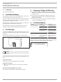 4
4
-
 5
5
-
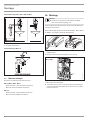 6
6
-
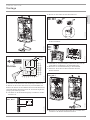 7
7
-
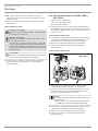 8
8
-
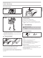 9
9
-
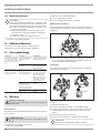 10
10
-
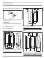 11
11
-
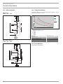 12
12
-
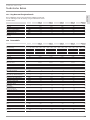 13
13
-
 14
14
-
 15
15
-
 16
16
-
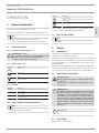 17
17
-
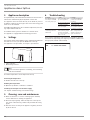 18
18
-
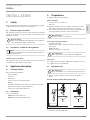 19
19
-
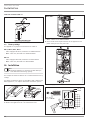 20
20
-
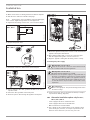 21
21
-
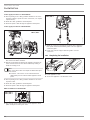 22
22
-
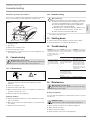 23
23
-
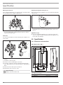 24
24
-
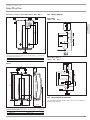 25
25
-
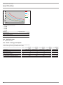 26
26
-
 27
27
-
 28
28
-
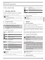 29
29
-
 30
30
-
 31
31
-
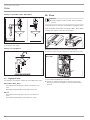 32
32
-
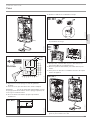 33
33
-
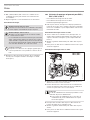 34
34
-
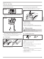 35
35
-
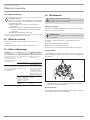 36
36
-
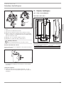 37
37
-
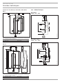 38
38
-
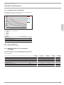 39
39
-
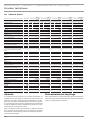 40
40
-
 41
41
-
 42
42
-
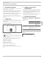 43
43
-
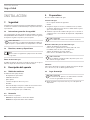 44
44
-
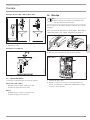 45
45
-
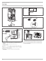 46
46
-
 47
47
-
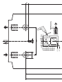 48
48
-
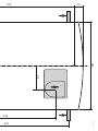 49
49
-
 50
50
-
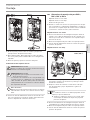 51
51
-
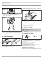 52
52
-
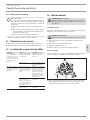 53
53
-
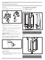 54
54
-
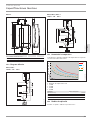 55
55
-
 56
56
-
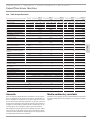 57
57
-
 58
58
-
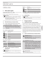 59
59
-
 60
60
-
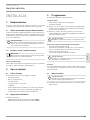 61
61
-
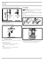 62
62
-
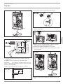 63
63
-
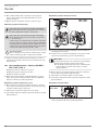 64
64
-
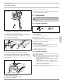 65
65
-
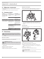 66
66
-
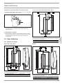 67
67
-
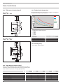 68
68
-
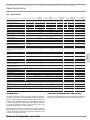 69
69
-
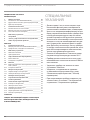 70
70
-
 71
71
-
 72
72
-
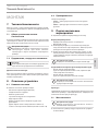 73
73
-
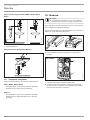 74
74
-
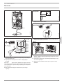 75
75
-
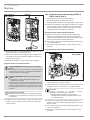 76
76
-
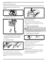 77
77
-
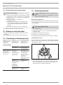 78
78
-
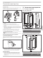 79
79
-
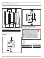 80
80
-
 81
81
-
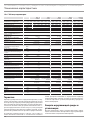 82
82
-
 83
83
-
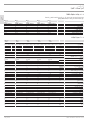 84
84
-
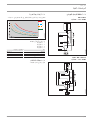 85
85
-
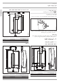 86
86
-
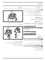 87
87
-
 88
88
-
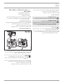 89
89
-
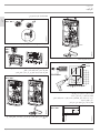 90
90
-
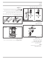 91
91
-
 92
92
-
 93
93
-
 94
94
-
 95
95
-
 96
96


STIEBEL ELTRON DHC 3-8 Operation Instruction
- Categoría
- Calentadores espaciales
- Tipo
- Operation Instruction
en otros idiomas
- français: STIEBEL ELTRON DHC 3-8
- polski: STIEBEL ELTRON DHC 3-8
Artículos relacionados
-
STIEBEL ELTRON PEG 13-24 Operation Instruction
-
-
-
-
-
-
-
-
-
Otros documentos
-
GYS MULTICHARGE STATION DHC 54 E Ficha de datos
-
Siemens DH04101 Manual de usuario
-
Sony TC-TX333 El manual del propietario
-
-
-
GYS BLUETOOTH BATTERY TESTER BTW 300 DHC El manual del propietario
-
Toto TBP02303 Instrucciones de operación
-