Yamaha S30 Manual de usuario
- Categoría
- Instrumentos musicales
- Tipo
- Manual de usuario

OWNER’S MANUAL
MUSIC SYNTHESIZER
OWNER’S MANUAL
MUSIC SYNTHESIZER

SPECIAL MESSAGE SECTION
This product utilizes batteries or an external power supply
(adapter). DO NOT connect this product to any power supply or
adapter other than one described in the manual, on the name
plate, or specifically recommended by Yamaha.
WARNING: Do not place this product in a position where any-
one could walk on, trip over ,or roll anything over power or con-
necting cords of any kind. The use of an extension cord is not
recommended! IF you must use an extension cord, the minimum
wire size for a 25' cord (or less ) is 18 AWG. NOTE: The smaller
the AWG number ,the larger the current handling capacity. For
longer extension cords, consult a local electrician.
This product should be used only with the components supplied
or; a cart, rack, or stand that is recommended by Yamaha. If a
cart, etc., is used, please observe all safety markings and
instructions that accompany the accessory product.
SPECIFICATIONS SUBJECT TO CHANGE:
The information contained in this manual is believed to be cor-
rect at the time of printing. However, Yamaha reserves the right
to change or modify any of the specifications without notice or
obligation to update existing units.
This product, either alone or in combination with an amplifier
and headphones or speaker/s, may be capable of producing
sound levels that could cause permanent hearing loss. DO NOT
operate for long periods of time at a high volume level or at a
level that is uncomfortable. If you experience any hearing loss
or ringing in the ears, you should consult an audiologist.
IMPORTANT: The louder the sound, the shorter the time period
before damage occurs.
Some Yamaha products may have benches and / or accessory
mounting fixtures that are either supplied with the product or as
optional accessories. Some of these items are designed to be
dealer assembled or installed. Please make sure that benches
are stable and any optional fixtures (where applicable) are well
secured BEFORE using.
Benches supplied by Yamaha are designed for seating only. No
other uses are recommended.
NOTICE:
Service charges incurred due to a lack of knowledge relating to
how a function or effect works (when the unit is operating as
designed) are not covered by the manufacturer’s warranty, and
are therefore the owners responsibility. Please study this manu-
al carefully and consult your dealer before requesting service.
ENVIRONMENTAL ISSUES:
Yamaha strives to produce products that are both user safe and
environmentally friendly. We sincerely believe that our products
and the production methods used to produce them, meet these
goals. In keeping with both the letter and the spirit of the law, we
want you to be aware of the following:
Battery Notice:
This product MAY contain a small non-rechargeable battery
which (if applicable) is soldered in place. The average life span
of this type of battery is approximately five years. When replace-
ment becomes necessary, contact a qualified service represen-
tative to perform the replacement.
This product may also use “household” type batteries. Some of
these may be rechargeable. Make sure that the battery being
charged is a rechargeable type and that the charger is intend-
ed for the battery being charged.
When installing batteries, do not mix batteries with new, or with
batteries of a different type. Batteries MUST be installed cor-
rectly. Mismatches or incorrect installation may result in over-
heating and battery case rupture.
Warning:
Do not attempt to disassemble, or incinerate any battery. Keep
all batteries away from children. Dispose of used batteries
promptly and as regulated by the laws in your area. Note: Check
with any retailer of household type batteries in your area for bat-
tery disposal information.
Disposal Notice:
Should this product become damaged beyond repair, or for
some reason its useful life is considered to be at an end, please
observe all local, state, and federal regulations that relate to the
disposal of products that contain lead, batteries, plastics, etc. If
your dealer is unable to assist you, please contact Yamaha
directly.
NAME PLATE LOCATION:
The name plate is located on the bottom of the product. The
model number, serial number, power requirements, etc., are
located on this plate. You should record the model number, seri-
al number, and the date of purchase in the spaces provided
below and retain this manual as a permanent record of your pur-
chase.
Model
Serial No.
Purchase Date
PLEASE KEEP THIS MANUAL
92-BP (bottom)

PRECAUTIONS
PLEASE READ CAREFULLY BEFORE PROCEEDING
* Please keep these precautions in a safe place for future reference.
• Do not open the instrument or attempt to disassemble the internal parts or
modify them in any way. The instrument contains no user-serviceable parts. If
it should appear to be malfunctioning, discontinue use immediately and have
it inspected by qualified Yamaha service personnel.
• Do not expose the instrument to rain, use it near water or in damp or wet con-
ditions, or place containers on it containing liquids which might spill into any
openings.
• If the AC adaptor cord or plug becomes frayed or damaged, or if there is a
sudden loss of sound during use of the instrument, or if any unusual smells
or smoke should appear to be caused by it, immediately turn off the power
switch, disconnect the adaptor plug from the outlet, and have the instrument
inspected by qualified Yamaha service personnel.
• Use the specified adaptor (PA-5C or an equivalent recommended by Yamaha)
only. Using the wrong adaptor can result in damage to the instrument or over-
heating.
• Before cleaning the instrument, always remove the electric plug from the out-
let. Never insert or remove an electric plug with wet hands.
• Check the electric plug periodically and remove any dirt or dust which may
have accumulated on it.
CAUTION
Always follow the basic precautions listed below to avoid the possibility of physical injury to you or others, or damage to the
instrument or other property. These precautions include, but are not limited to, the following:
• Do not place the AC adaptor cord near heat sources such as heaters or radi-
ators, and do not excessively bend or otherwise damage the cord, place heavy
objects on it, or place it in a position where anyone could walk on, trip over,
or roll anything over it.
• When removing the electric plug from the instrument or an outlet, always hold
the plug itself and not the cord.
• Do not connect the instrument to an electrical outlet using a multiple-con-
nector. Doing so can result in lower sound quality, or possibly cause over-
heating in the outlet.
• Unplug the AC power adaptor when not using the instrument, or during elec-
trical storms.
• Before connecting the instrument to other electronic components, turn off the
power for all components. Before turning the power on or off for all compo-
nents, set all volume levels to minimum. Also, be sure to set the volumes of
all components at their minimum levels and gradually raise the volume con-
trols while playing the instrument to set the desired listening level.
• Do not expose the instrument to excessive dust or vibrations, or extreme cold
or heat (such as in direct sunlight, near a heater, or in a car during the day) to
prevent the possibility of panel disfiguration or damage to the internal com-
ponents.
• Do not use the instrument near other electrical products such as televisions,
radios, or speakers, since this might cause interference which can affect prop-
er operation of the other products.
• Do not place the instrument in an unstable position where it might acciden-
tally fall over.
• Before moving the instrument, remove all connected adaptor and other cables.
• When cleaning the instrument, use a soft, dry cloth. Do not use paint thinners,
solvents, cleaning fluids, or chemical-impregnated wiping cloths. Also, do
not place vinyl, plastic or rubber objects on the instrument, since this might
discolor the panel or keyboard.
• Do not rest your weight on, or place heavy objects on the instrument, and do
not use excessive force on the buttons, switches or connectors.
• Use only the stand specified for the instrument. When attaching the stand or
rack, use the provided screws only. Failure to do so could cause damage to
the internal components or result in the instrument falling over.
• Do not operate the instrument for a long period of time at a high or uncom-
fortable volume level, since this can cause permanent hearing loss. If you
experience any hearing loss or ringing in the ears, consult a physician.
■ REPLACING THE BACKUP BATTERY
• This instrument contains a non rechargeable internal backup battery which
permits internal data to remain stored even when the power is off. When the
backup battery needs replacing, the message "Change internal battery" will
display in the LCD. When this happens, immediately back up your data, then
have qualified Yamaha service personnel replace the backup battery.
• Do not attempt to replace the backup battery yourself, in order to prevent the
possible serious hazards. Always have qualified Yamaha service personnel
replace the backup battery.
• Never place the backup battery in a location that a child can reach, since a
child might accidentally swallow the battery. If this should happen, consult a
physician immediately.
■ SAVING USER DATA
• Always save data to a Memory Card (SmartMedia) frequently, in order to help
prevent the loss of important data due to a malfunction or user operating
error.
Yamaha cannot be held responsible for damage caused by improper use
or modifications to the instrument, or data that is lost or destroyed.
Always turn the power off when the instrument is not in use.
WARNING
Always follow the basic precautions listed below to avoid the possibility of serious injury or even death from electrical shock,
short-circuiting, damages, fire or other hazards. These precautions include, but are not limited to, the following:
(3)-6

4
Introduction
Thank you for purchasing the Yamaha S30 Music Synthesizer.
Your new S30 synthesizer incorporates the highly-acclaimed AWM2 synthesis engine, allowing the
creation of super-realistic sounds. It supports optional Plug-in Boards that provide other synthesis
engines of your choice, enabling the production of cutting edge synthesizer sounds.
You can play all these sounds using the synthesizer’s automatic playback facilities such as the built-in
Arpeggiator and Sequencer. The Quick Access feature lets you access various genres of sounds
quickly and directly via the front panel.
Other features include Effects and Control Sets (for controlling various sound parameters in real time
using different controllers.) These features make this synthesizer ideal for every kind of live
performance or studio work.
When editing a sound, you can use the [PAGE] knob to switch between screens and five other knobs
plus the [DATA] knob for changing parameter values. This makes the process of editing sounds much
easier and smoother. To make the most use of your synthesizer, you are encouraged to read through
this manual. After reading the manual, please keep it in a convenient and safe place for future
reference.
About This Manual
This manual is basically divided into two sections:
■ Basics Section (Page 6)
Explains how to get started with the synthesizer, its overall structure, and how to use its main features and
functions.
■ Reference Section (Page 59)
Explains the parameters in the synthesizer’s various Modes.
Package Contents
• Owner’s Manual (this book)
• Data List
• PA-5C AC Adaptor*
• Installation Guide
• CD-ROM (TOOLS for S80/S30 & CS6x/CS6R)
*May not be included in your area. Please check with your Yamaha dealer.
The Included CD-ROM
Application software for your synthesizer included on this CD-ROM. The Voice Editor application lets you edit
your synthesizer's sounds through a graphical user interface. The Card Filer application lets you exchange data
between your synthesizer and computer. Details are given in the separate Installation Guide or the on-line
manuals included with the software.
Never attempt to play back the track1, in which the application software is located, on an audio CD player. Doing so may
result in damage to your hearing as well as to your CD player/audio speakers.
Copying of the commercially available music sequence data and/or digital audio files is strictry prohibited except for your personal use.
The illustrations and LCD screens as shown in this owner’s manual are for instructional purposes only, and may appear somewhat different from
those on your instrument.
The company names and product names in this Owner’s Manual are the trademarks or registered trademarks of their respective companies.

5
Basics Section
The Controls & Connectors................................6
Before Use ..........................................................9
Power Supply ..........................................................9
Connections ............................................................9
Powering Up..........................................................14
Basic Operations ..............................................16
Selecting a Mode ..................................................16
Selecting a Screen ................................................18
Entering Data........................................................19
Demo Playback ................................................21
Voices and Performances ..................................22
Playing a Voice......................................................22
Playing a Performance..........................................24
An Overview of the S30 ..................................26
Controller Section ................................................26
Sequencer Section ................................................26
Tone Generator Section ......................................27
Effects Section ......................................................29
About the Modes ..............................................30
Voices ................................................................31
An Overview of Voices/Waves ............................32
Waves ....................................................................33
Performances ....................................................34
Ideal for Playing Live ......................................35
1 Arpeggiator ........................................................36
2 Using Controllers ..............................................38
Voice Edit..........................................................45
Effects....................................................................50
Using as a Master Keyboard
(Performance Mode) ........................................52
Using as a Multitimbral Tone Generator
(Performance Mode) ........................................57
Reference Section
Voice Mode........................................................59
Voice Play ..............................................................59
Voice Edit ..............................................................63
Voice Job Mode ..................................................100
Voice Store ..........................................................101
Performance Mode ........................................102
Performance Play ..............................................102
Performance Edit ..............................................106
Performance Job Mode ......................................123
Performance Store ..............................................124
Sequence Play Mode ......................................125
Utility Mode....................................................127
Utility Job Mode ................................................134
Card Mode ......................................................135
Appendix
About the Plug-in Boards (Optional) ............141
Display Messages ............................................144
Troubleshooting..............................................145
Specifications..................................................148
Index ..............................................................149
Table of Contents
Basics Section
Reference
Section
Voice Mode
Performance
Mode
Sequence Play
Mode
Utility Mode
Card Mode
Appendix

6
Basics
Section
Basics
Section
1PITCH bend wheel (Page 38)
Controls the pitch bend effect. You can also assign
other functions to this controller.
2MODULATION wheel (Page 38)
Controls the modulation effect. You can also assign
other parameters functions to this controller.
3[VOLUME] Slider (Page 15)
Adjusts the master volume. Move the slider upwards
to raise the output level from the OUTPUT L/R
jacks and the PHONES jack.
4Control Sliders (Page 56)
In Master Keyboard Mode, the sliders can be used to
control various functions assigned to them (as
Control Change messages). Each slider controls each
of four Zones.
5[SHIFT] key (Page 18)
In Voice or Performance Play Mode, a screen for
viewing or setting the Octave parameter and the
MIDI Transmit channel (Page 18) is shown when
you press the [SHIFT] key. In any of the Edit
Modes, when pressing this key while turning the
[PAGE] knob, a menu screen is displayed and you
can quickly switch between Edit Mode screens (Page
18). If while holding this key you turn one of Knobs
[A] ~ [C], [1] ~ [2], [DATA] knob, or press either
[INC/YES] or [DEC/NO] key, you can move the
cursor without a parameter value being changed
(Page 19).
6[PAGE] knob (Page 18)
Switches between screens in each Mode. Each Mode
includes several screens.
7LCD (Liquid Crystal Display)
This is a backlit 2-line display.
8Knobs [A], [B], [C], [1] and [2] (Page 19)
In each Play Mode, these knobs mainly control the
functions respectively assigned to them.
In each Edit Mode, each knob is used to enter a
value for the associated parameter shown in the
display. Depending on the operation or the screen
you are working in, these knobs will function
differently.
Knobs [A] to [C] can be assigned to system control
functions (Pages 41, 129). Knobs [1] and [2] can be
assigned control functions that affect Voices (Pages
42, 69).
CONTROL SLIDER
1 2 3 4
SHIFT
PART/ELEMENT
ASSIGNABLE NKOB
PAGE
DATA
EF
BYPASS
MASTER
KEYBOARD
EXIT ENTER
COMPARE
EDIT JOB
UTILITY CARD
DEC/NO INC/YES
A B C 1 2
VOLUME
MUSIC SYNTHESIZER
Modular Synthesis Plug-in System
MODE
STANDBY
ON DC IN PHONES
OUTPUT OUTPUT
CARD
3.3V
L/MONO R FOOT
CONTROLLER
FOOT
SWITCH
TO HOST
MIDI
OUTIN THRU
VOICE STORE
SEQ
PLAY
PLAY/
STOP
PERFORM
PLGEXT
DRUMDRUM
QUICK
ACCESS
INTPRE 2PRE1
A B
A. PIANO E. PIANO ORGAN GTR
/
BASS STRINGS BRASS SYNTH OTHER
C D E F G H
1 2 3 4 5 6 7 8
9 10 11 12 13 14 15 16
1 3 4 5 96 7 * (2 8 ) ^ &
!
@
º¡
#
$
%
The Controls & Connectors
Front Panel
Basics Section

7
Basics
Section
9[DATA] knob (Page 20)
Use this to increase or decrease the value of the
parameter at which the cursor is positioned.
)[EF BYPASS] key (Page 51)
Enables/dsiables the Effect Bypass. Press the key
(its LED will light) to bypass the effects used with
the current Voice or Performance. The bypassed
effects (Reverb, Chorus, or Insertion) are specified in
Utility Mode (Page 128).
![MASTER KEYBOARD] key (pages 52, 106)
The S30 keyboard can work as MIDI master
keyboard in Performance mode. When the key is
pressed and switched on (the LED will light), the
keyboard can play and control multiple MIDI sound
modules connected to the S30.
@[EXIT] key (Page 18)
The menus and screens of the S30 have a
hierarchical structure. Press this key exit from the
current screen and return to the previous level in the
hierarchy.
#[ENTER] key (Pages 19, 20)
While selecting a Memory or Bank for Voice or
Performance, press this key to determine such a
memory location. Also, use this key to execute a Job
or a Store operation.
$[DEC/NO] key (Page 19)
Use this to decrease the value of the parameter at
which the cursor is positioned. Also use it to cancel
a Job or a Store operation.
%[INC/YES] key (Page 19)
Use this to increase the value of the parameter at
which the cursor is positioned. Also use it to
execute a Job or a Store operation.
^MODE keys (Page 16)
Press these to keys to select Voice, Performance,
Utility or other Modes.
&SEQ controls (Pages 21, 125)
Press the [SEQ PLAY] key to enter Sequence Play
Mode. Here, you can play a MIDI file from Memory
Card. Use the [PLAY/STOP] key to start or stop
playback of the currently selected file.
*MEMORY keys (Pages 22, 24, 60, 104)
Using one of these keys, you can select a Voice or
Performance Memory. Press the [ENTER] key to
select the Memory. In Performance Mode, the [PLG]
key can be used to select the Plug-in Part. The
[PRE1] and [PRE2] keys select “Common” (for all
Parts).
([QUICK ACCESS] key (Page 63)
When you press the [QUICK ACCESS] key (its LED
will light), you can use BANK keys [A] to [H] to
directly select Categories and PROGRAM keys [1] to
[16] to quickly select Voices.
ºBANK [A] to [H] keys (Pages 60, 104)
Each key selects a Voice or Performance Bank. Each
Bank contains sixteen Voices or Performances. In
Voice Edit Mode, each of the BANK [A] to [D] keys
selects a Voice’s Element (ELEMENT SELECT)
while each of the BANK [E] to [H] keys turns the
associated Voice’s Element on or off (ELEMENT
ON/OFF) (Page 46). When you activate Master
Keyboard Mode by pressing the [MASTER
KEYBOARD] key, these key ([A] to [D]) can
respectively select Zones 1 to 4 if the Master
Keyboard Mode setting is 4 zone in Performance Edit
Mode.
¡PROGRAM/PART [1] to [16] keys (Pages 60,
104)
Each key selects a Voice or Performance from the
current Bank. In Voice Edit Mode, each
PROGRAM/PART key selects an associated edit
menu (Page 65). In Performance Mode, these keys
select Parts [1] to [16], respectively.

8
Basics
Section
Basics
Section
1CARD slot (Page 135)
Insert a Memory Card here to transfer various data
to/from the instrument. Read carefully the
precautions on use of a Memory Card (Page 135)
before using a card.
2MIDI IN, OUT, and THRU connectors (Page 11)
MIDI IN receives MIDI messages from an external
MIDI device. Use this connector to control the
synthesizer from an external MIDI device. MIDI
OUT sends out MIDI messages generated by the
synthesizer, such as notes played on the keyboard or
panel control/knob variations, to an external MIDI
sound module or device. MIDI THRU just reflects
the MIDI messages received at MIDI IN. Connect
other MIDI devices here.
3HOST SELECT switch (Page 12)
Select the type of computer connected to the
synthesizer via the TO HOST connector .
4TO HOST terminal
Connect a computer here using an optional serial
computer cable (Page 12).
5FOOT SWITCH jack (Pages 13, 39)
Connect an optional Foot switch (FC4 or FC5) here.
Using the foot switch, you can control of a range of
on or off a specific function by foot, as assigned on
the instrument. (Pages 43, 129)
6FOOT CONTROLLER jack (Pages 13, 39)
An optional foot controller (FC7, etc.) can be
connected here. Using the foot controller, you can
control tones, pitches, volumes or the like by foot.
7OUTPUT L/MONO and R jack (Page 10)
Line level audio signals are output via these phone
jacks. For monophonic output, use just the
L/MONO jack.
8PHONES jack (Page 10)
Connect a pair of headphones here.
9DC IN terminal (Page 9)
For connecting an appropriate AC power adaptor
(PA-5C or an equivalent recommended by Yamaha)
to supply power to the S30.
)STANDBY/ON switch (Page 14)
Use this to switch the synthesizer on or off.
Even when the switch is in the “STANDBY” position,
electricity is still flowing to the instrument at a
minimum level. When not using the S30 for an
extended period of time, be sure to unplug the AC
power adaptor from the wall AC outlet.
Rear Panel
3.3V
CARD
THRU OUT IN TO HOST
HOST SELECT
PC-1PC-2
MIDI Mac
FOOT
SWITCH
R
OUTPUT
L/MONO PHONES DC IN
STANDBY
ON
FOOT
CONTROLLER
MIDI
1 2 73 4 5 6 8 9 )

9
Basics
Section
Before Use
This section explains how to connect to an AC power source, audio and MIDI devices, and a computer
system. Only switch the synthesizer on after you have made all the necessary connections.
It is recommended that you read this section before using the synthesizer.
Power Supply
1Make sure that the instrument’s STANDBY/ON switch is at the STANDBY(off) position.
2Connect the PA-5C’s DC plug to the S30’s DC IN terminal on the instrument’s rear panel.
3Connect the adaptor’s AC plug to the nearest electrical outlet.
Do not attempt to use an AC adaptor other than the Yamaha PA-5C or an equivalent recommended by Yamaha.
The use of an incompatible adaptor may cause irreparable damage to the S30, and may even pose a serious shock
hazard! ALWAYS UNPLUG THE AC ADAPTOR FROM THE AC POWER OUTLET WHEN THE S30 IS NOT
IN USE.
Connections
Connecting to External Audio Equipment
Since the synthesizer has no built-in speakers, you need to monitor its sound output via external
audio equipment. Alternatively, you could use a pair of headphones.
There are several methods of connecting to external audio equipment, as described in the following
illustrations.
Connecting Stereo Powered Speakers
A pair of powered speakers can accurately produce the instrument’s rich sounds with their own pan
and effect settings. Connect your powered speakers to the OUTPUT L/MONO and R jacks on the
rear panel.
When using just one powered speaker, connect it to the OUTPUT L/MONO jack on the rear panel.
S30
Headphones
PHONES
OUTPUT
L/MONO
OUTPUT R
INPUT
Powered speaker (Left) Powered speaker (Right)
MUSIC SYNTHESIZER
Modular Synthesis Plug-in System
INPUT
Rear panel
3.3V
CARD
THRU OUT IN TO HOST
HOST SELECT
PC-1PC-2
MIDI Mac
FOOT
SWITCH
R
OUTPUT
L/MONO PHONES DC IN
STANDBY
ON
FOOT
CONTROLLER
MIDI
2 DC IN
1 STANDBY
3 To electrical output

10
Basics
Section
Connecting to a Mixer
If you want to integrate the S30 into a larger system with other instruments and additional audio
processing capabilities, connect it to a mixer, amplifier and stereo monitor system as shown below.
Connecting a pair of headphones does not affect audio output from the OUTPUT (L/MONO and R) jacks.
You can monitor the same sounds via headphones and at the OUTPUT jacks.
12345678910111213141516LR
Headphones
Mixer
Speaker
Amplifier
L
OUTPUT L
R
OUTPUT L /
MONO
PHONES
R
R
S30
MUSIC SYNTHESIZER
Modular Synthesis Plug-in System

11
Basics
Section
Connecting External MIDI Equipment
You can connect an external MIDI device using a MIDI cable (available separately) and control it from
this synthesizer. You can also use an external MIDI keyboard or sequencer to control the
synthesizer’s internal sounds. This section introduces several different applications of MIDI.
The HOST SELECT switch on the rear panel should be set to “MIDI.” Otherwise, MIDI information will not be
transmitted from the synthesizer’s MIDI OUT connector.
Controlling from an External MIDI Keyboard
Controlling an External MIDI Keyboard
Recording and Playback using an External MIDI Sequencer
MIDI IN
MIDI OUTMIDI IN
MIDI OUT
External MIDI
sequencer
HOST SELECT
PC-2 PC-1
MIDI Mac
S30
MUSIC SYNTHESIZER
Modular Synthesis Plug-in System
MIDI OUT
MIDI IN
HOST SELECT
PC-2 PC-1
MIDI Mac
External MIDI keyboard
or synthesizer
S30
MUSIC SYNTHESIZER
Modular Synthesis Plug-in System
MIDI OUT
MIDI IN
External MIDI keyboard
or synthesizer
HOST SELECT
PC-2 PC-1
MIDI Mac
S30
MUSIC SYNTHESIZER
Modular Synthesis Plug-in System

12
Basics
Section
Controlling Another MIDI Device via MIDI THRU
With the above MIDI connections, you can send MIDI data from the MIDI OUT connector while
MIDI data from the external sequencer can be sent to an external MIDI synthesizer via the MIDI
THRU jack.
The MIDI cable should be no greater than 15 meters in length, and there should be no more than three devices in
a MIDI chain (chained in series via each unit’s MIDI THRU). To connect more units, use a MIDI Thru Box for
parallel connections. You may encounter errors if the MIDI cables are too long or if too many devices are chained
together via their MIDI THRU connectors.
Connecting to a Personal Computer
When a computer is connected, it can be used to control the synthesizer and to transfer synthesizer
data to/from computer via MIDI. With the included Voice Editor program, for instance, you can edit
the synthesizer’s Voices. Using another program – Card Filer – you can transfer files between the
computer and the Memory Card inserted in the synthesizer’s CARD slot.
There are two ways to connect your synthesizer to a computer:
1: Serial connection (the computer’s serial port to the synthesizer’s TO HOST terminal)
2: MIDI connection (the computer’s MIDI interface or external MIDI interface to the
synthesizer’s MIDI IN and OUT)
Different computers require different connections, as follows.
1: Serial Port to TO HOST
IBM PC/AT
Macintosh
TO
HOST
Serial cable
HOST SELECT
PC-2 PC-1
MIDI Mac
Apple Macintosh
PS422
(Modem or
Printer port)
S30
MUSIC SYNTHESIZER
Modular Synthesis Plug-in System
IBM PC/AT and compatibles
RS-232C
(DB9)
IBM
Personal System/V
PS/V
Personal System/V
TO
HOST
Serial cable
HOST SELECT
PC-2 PC-1
MIDI Mac
S30
MUSIC SYNTHESIZER
Modular Synthesis Plug-in System
MIDI OUT
MIDI IN
External MIDI synthesizer
MIDI IN
MIDI THRU
MIDI OUT
MIDI IN
External MIDI
sequencer
External MIDI
synthesizer
HOST SELECT
PC-2 PC-1
MIDI Mac
S30
MUSIC SYNTHESIZER
Modular Synthesis Plug-in System

13
Basics
Section
2: MIDI Interface to MIDI IN and OUT
Using the computer’s MIDI interface
Using an external MIDI interface
You will need to an appropriate MIDI application (sequencer, editor, etc.) for your computer platform.
Connecting Controllers
The S30 has controller jacks on the rear panel, including FOOT SWITCH and FOOT CONTROLLER.
You can connect optional controllers like a Foot Switch (the FC4 or FC5) and Foot Controller (the
FC7) to control tone, volume, pitch and other parameters.
Details about how to these controllers are given on Page 39.
3.3V
CARD
THRU OUT IN TO HOST
HOST SELECT
PC-1PC-2
MIDI Mac
FOOT
SWITCH
R
OUTPUT
L/MONO PHONES DC IN
STANDBY
ON
FOOT
CONTROLLER
MIDI
FOOT
SWITCH
FOOT
CONTROLLER
FC4 or FC5 FC7
MIDI Interface
MIDI OUT
MIDI IN
MIDI IN MIDI OUT
HOST SELECT
PC-2 PC-1
MIDI Mac
Computer
S30
MUSIC SYNTHESIZER
Modular Synthesis Plug-in System
Computer with MIDI interface
Serial cable
HOST SELECT
PC-2 PC-1
MIDI Mac
MIDI OUT
MIDI
OUT
MIDI
IN
MIDI IN
IBM
Personal System/V
PS/V
Personal System/V
S30
MUSIC SYNTHESIZER
Modular Synthesis Plug-in System

14
Basics
Section
Powering Up
Power-on Procedure
When you have made all the necessary connections between your synthesizer and any other devices,
make sure that all volume settings are turned down all the way to zero. Then turn on the every device
in your setup in the order of MIDI masters (senders), MIDI slaves (receivers), then audio equipment
(mixers, amplifiers, speakers, etc.). This ensures the smooth flow of signals from the first device to the
last (first MIDI, then audio).
When powering down the setup, first turn down the volume for each audio devices, then switch off
each device in the reverse order (first audio devices, then MIDI).
When the S30 as MIDI receiver:
Switching the S30 On
In order to avoid possible damage to the speakers or other connected electronic equipment, always switch on the
power of the S30 before switching on the power of the amplified speakers or mixer and amplifier. Likewise,
always switch off the power of the S30 after switching off the power of the amplified speakers or mixer and
amplifier.
Even when the switch is in the “STANDBY” position, electricity is still flowing to the instrument at a minimum
level. When not using the S30 for an extended period of time, be sure to unplug the AC power adaptor from the
wall AC outlet.
Before you switch your synthesizer on or off, first turn down the volume of any audio equipment connected to it.
1Press the STANDBY/ON switch.
2A splash screen is displayed briefly.
3The Voice or Performance Play Mode screen appears next.
VCE Play) PRE1:001(A01)[Pf:StereoGrnd]
EQLow-G EQMid-G EQHi-G ChoSend RevSend
PHONES DC IN
STANDBY
ON
MIDI sender Audio equipment (first mixer, then amplifier)
1 2 3 4 5 6 7 8 9 10 11 12 13 14 15 16 L R
POWER
ON!
S30
(MIDI receiver)
MUSIC SYNTHESIZER
Modular Synthesis Plug-in System

15
Basics
Section
If you have a Memory Card inserted in the instrument’s CARD slot or an optional Plug-in Board
installed, you may see other screens before the Voice or Performance Play Mode screen is displayed.
If a previously used Memory Card is inserted in the CARD slot, you will see a screen while files in
EXT Memory are being loaded.
If a new Memory Card (one never used on the instrument) is inserted in the CARD slot, you will see
a screen while a basic file is being created in EXT Memory.
If you have a Plug-in Board installed, you will see a screen that confirms the presence of the Plug-in
Board.
The final screen after the power-on sequence may change depending on the Power On Mode setting available
Utility Mode (Page 128).
4Turn up the amplifier’s volume as necessary.
5Adjust the synthesizer’s [VOLUME] slider to set an appropriate volume level.
About Memory Cards
You can save various kinds of data - Voice, Performance, Plug-in, Sequence Chain and so on - onto
Memory Card. The built-in CARD slot can accept 3.3-volt Memory Cards (SmartMedia).
Before using a Memory Card, read through precautions on how to handle it (Page 135).
• Formatting a Memory Card
You cannot use a new Memory Card to save files immediately. The card must be formatted in Card
Mode (Page 140) beforehand.
• Saving and Loading Data
You can save various kinds of data as files on a formatted Memory Card. Each file on the card can be
loaded when required.
You can save and load data such as System, Voice, Performance, Plug-in, Sequence Chain or the like.
Since Sequence Chain data is held temporarily in the synthesizer’s buffer memory and will be lost
once you switch it off, you need to save such data onto the Memory Card first.
Details about formatting a Memory Card, saving and loading data, and the recognized file types are
given on Page 136.

16
Basics
Section
Basic Operations
This section gives some basic explanations about operating the synthesizer.
Selecting a Mode
There are several operation Modes — Voice Play Mode, Performance Play Mode, etc. — each of which
enables you to work efficiently with the synthesizer’s various functions.
An overview of each Mode is given on Page 30.
There are separate Play Modes for Voices and Performances. To enter each of these Modes, use the
appropriate MODE key ([VOICE] for Voice Play Mode, [PERFORM] for Performance Play Mode).
There are also separate Edit and Job Modes for Voices and Performances. To enter Edit or Job Mode,
simply press the [EDIT] or [JOB] key while in each respective Play Mode.
Similarly, pressing the [STORE] key in Voice or Performance Mode takes you into Store Mode where
you can store Voices or Performances.
Other Modes include Utility Mode where you can specify system settings, Card Mode where you can
perform tasks related to the Memory Card, and Sequence Mode where you can play back MIDI song
files or create a sequence chain. (Press the [UTILITY] key for Utility Mode, the [CARD] key for Card
Mode and the [SEQ PLAY] key for Sequence Mode.)
STOREVOICE
M
ODE
UTILITY
EDIT JOB
PLAY
/
STOP
CARD
SEQ
PLAY
PERFORM
COMPARE
6
43
82
75
1
Play Modes
1 Voice Play Mode (Page 59)
Press the [VOICE] key (its LED
will light) to enter Voice Play
Mode. To exit to another Mode,
simply press the respective key
for that Mode.
2 Performance Play Mode
(Page 102)
Press the [PERFORM] key (its
LED will light) to enter
Performance Mode. To exit to
another Mode, simply press the
respective key for that Mode.
PFM Play) INT:001(A01)[--:Init Perf ]
EQLow-G EQMid-G EQHi-G ------- -------
VCE Play) PRE1:001(A01)[Sq:Generation]
EQLow-G EQMid-G EQHi-G FLT-Rez HPF
Edit Modes
When in each Play Mode, you
can swiftly switch to each
respective Edit Mode by simply
pressing the [EDIT] key (its
LED will light).
3 Voice Edit Mode (Page 63)
Press the [EDIT] key in Voice
Play Mode. To exit to another
Mode, simply press the
respective key for that Mode or
press the [EXIT] key to return
to Voice Play Mode.
GEN Name) Ctgry a-Z 0-? Cursor
C 1234 [Pf:Init Voice]
3 Performance Edit Mode
(Page 106)
Press the [EDIT] key while in
Performance Play Mode. To exit
to another Mode, simply press
the respective for that Mode or
press the [EXIT] key to return to
Performance Play Mode.
GEN Name) Ctgry a-Z 0-? Cursor
Common [--:Init Perf ]

17
Basics
Section
Job Modes
When in each Play Mode, you
can swiftly switch to each
respective Job Mode by simply
pressing the [JOB] key (its LED
will light).
4 Voice Job Mode (Page 100)
Press the [JOB] key in Voice Play
Mode. To exit to another Mode,
simply press the respective key
for that Mode or press the
[EXIT] key to return to Voice
Play Mode.
4 Performance Job Mode
(Page 123)
Press the [JOB] key while in
Performance Play Mode. To exit
to another Mode, simply press
the respective for that Mode or
press the [EXIT] key to return to
Performance Play Mode.
4 Utility Job Mode (Page 134)
Press the [JOB] key in Utility
Mode. To exit to another Mode,
press the respective key for that
Mode or press the [EXIT] key to
return to Utility Mode.
UTIL Factory Set)
Job
PFM Initialize)
Job Current Perform
VCE Initialize)
Job Current Voice
Other Modes
5 Utility Mode (Page 127)
Press the [UTILITY] key (its
LED will light) to enter Utility
Mode. To exit to another Mode,
simply press the respective key
for that Mode.
6 Card Mode (Page 135)
Press the [CARD] key (its LED
will light) to enter Card Mode.
To exit to another Mode, simply
press the respective key for that
Mode.
7 Sequence Play Mode
(Page 125)
Press the [SEQ PLAY] key (its
LED will light) to enter
Sequence Play Mode. To exit to
another Mode, simply press the
respective key for that Mode.
When MIDI system exclusive
messages are received from an
external MIDI device, the LED
for the currently selected Play
Mode (VOICE or PERFORM)
will blink.
8 Store Modes
(Pages 101, 124)
When in each Play or Edit
Mode, you can swiftly switch to
each respective Store Mode by
simply pressing the [STORE]
key. To exit to another Mode,
simply press the respective key
for that Mode or press the
[EXIT] key to return to Play
Mode.
VCE [Sq:Generation] >[Pf:Slamming ]
Store INT:001(A01)
SEQ) File:[ ] Perf
Chain00 001 ⁄= 120 Meas=001 INT:128
Save) Type File A-? Cursor
Card all ***[NEWFILE .S2A]
MSTR TG) Vol NoteShift Tune
Sys 127 +63 +102.3c

18
Basics
Section
Selecting a Screen
You can switch between screens using the [PAGE]
knob and pressing [SHIFT], [PROGRAM/PART],
[EXIT] and [ENTER] keys.
[PAGE] Knob
Usually, there are several screens and sub-screens
in each Mode. Use the [PAGE] knob to switch
between screens.
As shown below, the “ ” indicator is displayed to
the left of the screen if there are more screens
before and after that which you are currently
viewing.
At the first in a series of screens, you will see the
“ ” indicator meaning that there are more screens
to follow, but none before it. At the last screen,
you will see the “ ” indicator meaning that there
are no more screens to follow.
[SHIFT] Key
If you hold down the [SHIFT] key in Voice Play
Mode, you can modify the parameters on screen
as follows.
SHIFT PAGE
PA RT
/
ELEMENT
DATAABC1 2
(Oct= +3) PRE1:128(H16)[Pf:GrandPiano]
(Tch= 1)
LFO Depth)
EL1234
Indicator
SHIFT PAGE AB
VCE Srch) PRE1:
Memory
Next screenPrevious screen
Some Modes have more screens. In this case, you
can use the [PAGE] knob while holding down the
[SHIFT] key to switch to a specific screen.
For example, if you use the [PAGE] knob while
hoilding down the [SHIFT] key in Voice Edit
Mode, the following screen is shown. Select a
specific item using the cursor (≥), then release the
[SHIFT] key to switch to the parameter screen for
that item.
The [SHIFT] key also has other functions, as
described in other sections in this manual.
PROGRAM/PART keys
In Voice Edit Mode, PROGRAM/PART keys can
be used to select the items shown under the keys
and to switch to their screens.
[EXIT] Key
Press the [EXIT] key to move up (exit) in the
hierarchical structure and return to the previous
screen.
The [EXIT] key also has other more functions, as
described in other sections in this manual.
DEC
/
NO INC
/
YES
EXIT ENTER
EF
BYPASS
MASTER
KEYBOARD
12345678
910111213141516
GENERAL QED ARPEGGIO CONTROL COM LFO EFFECT
OSC PITCH FILTER AMPLITUDE LFO EQ PLG
SHIFT PAGE
PART
/
ELEMENT
DATAABC1 2
GENíOther) Com:>GEN≥QED>ARP>CTL>LFO>EFF
EL1234 Elem:>OSC>PCH>FLT>AMP>LFO>EQ
Cursor

19
Basics
Section
[ENTER] Key
Normally, the [ENTER] key is used to apply
parameter settings. In some cases, however, the
following screen appears prompting you to press
the [ENTER] key.
The [ENTER] key has other functions, as described
in other sections in this manual.
Entering Data
You can use the knobs to directly alter their
respective parameters on the screen.
Alternatively, you can also move the cursor (≥) to
a parameter and set its value using the
[INC/YES] and [DEC/NO] keys, or the [DATA]
knob.
Knobs [A], [B], [C], [1]
and [2]
Each parameter in a screen is normally associated
with a knob ([A], [B], [C], [1] or [2]) below the
display. When you use one of these knobs, the
cursor (≥) moves to its respective parameter and
you can change its value. For instance, you can use
Knob [B] at the following screen to change the
Level setting. Turn the knob clockwise to increase
the value and anti-clockwise to decrease it.
SHIFT PAGE
PA RT
/
ELEMENT
DATAABC1 2
OSCíOut) Level Delay InsEF
EL1234 ≥ 96 0 ins2
EFFíEF1) Ctgry Type [ENTER]
C 1234 MOD Tremolo to Edit
DEC
/
NO INC
/
YES
EXIT ENTER
EF
BYPASS
MASTER
KEYBOARD
Moving the Cursor
By using a knob ([A], [B], [C], [1] or [2]) while
holding down the [SHIFT] key, you can move the
cursor (≥) to the respective parameter on the
screen without affecting its value.
[INC/YES] and [DEC/NO]
Keys
You can use the [INC/YES] key to increment a
parameter setting by one step, or the [DEC/NO]
key to decrement it. If you hold down either key,
the value is continuously changed.
You can also use these keys to answer “YES” or
“NO” when a confirmation message is displayed.
Moving the Cursor
By pressing the [INC/YES] or [DEC/NO] key
while holding down the [SHIFT] key, you can
move the cursor between parameters on the
screen without affecting their values.
SHIFT PAGE
PA RT
/
ELEMENT
DATAABC1 2
DEC
/
NO INC
/
YES
OSCíOut) Level Delay InsEF
EL1234 ≥ 96 0 ins2
DEC
/
NO INC
/
YES
SHIFT PAGE
PA RT
/
ELEMENT
DATAABC1 2
OSCíOut) Level Delay InsEF
EL1234 96 ≥ 0 ins2

20
Basics
Section
[DATA] Knob
Use this knob to change the value of the
parameter at which the cursor is positioned.
Turn the knob clockwise to increment the value
one click (step) at a time, or turn it anti-clockwise
decrement it.
Moving the Cursor
Turn the [DATA] knob clockwise or anti-
clockwise while holding down the [SHIFT] key to
move the cursor to a parameter in the screen
without affecting its value.
[ENTER] Key
Use this key to apply a setting (when it is
blinking, for example.). The [ENTER] key is also
used when executing a Job or Store operation, as
described in other sections of this manual.
DEC
/
NO INC
/
YES
EXIT ENTER
EF
BYPASS
MASTER
KEYBOARD
SHIFT PAGE
PA RT
/
ELEMENT
DATAABC1 2
OSCíOut) Level Delay InsEF
EL1234 ≥ 96 0 ins2
SHIFT PAGE
PA RT
/
ELEMENT
DATAABC1 2
OSCíOut) Level Delay InsEF
EL1234 ≥ 96 0 ins2
Types of Parameters (Absolute and Relative)
There are many ways to set parameters. Some
parameters require you to directly enter
numerical settings or alphabetic characters.
With others, you can choose from a number of
available settings. Furthermore, some types of
parameters are “absolute” whereas others are
“relative.”
For example, the absolute parameter in the
following illustration can be set to either
“Mono” or “Poly.” For other absolute
parameters such as Volume, the setting can be
any value between zero and 127. The Volume
setting has a linear, on-to-one relationship
with the actual volume, as shown in the graph
on the left.
However, relative parameters do not follow the
same relationship. The graph on the bottom
shows the role of the Velocity Offset
parameter. The value you have set here,
known as an “offset,” is added to, or
subtracted from, the actual value. With
Velocity Offset, the specified offset value is
added to, or subtracted from, the actual
velocity of the notes you play on the keyboard.
Sometimes, these types of relative parameters
are set as a percentage.
127
Volume
1 Volume (absolute)
0
Volume
offset added -10
Actual velocity
offset added +10
2 Velocity offset (relative)
0
-64
Offset
+64
QEDíLevel) Vol Pan RevSend ChoSend
C 1234 127 C 127 127
0~127
GEN Other) Mode Assign MicroTuning
C 1234 poly single 31:Indian
mono/poly

21
Basics
Section
Demo Playback
Several demo songs are supplied with this synthesizer. You can play them back as follows.
Make sure synthesizer is ready for playback. Details are given in the section “Before Use” on Page 9.
At the “SEQ Demo” screen, any data in the instrument’s internal memory (System, Internal Voices or the like)
will be overwritten by the data for the demo song. Important data should be saved to Memory Card (Page 137)
beforehand.
1Press the [SEQ PLAY] key to enter Sequence Play Mode. You will see the following screen.
There are two screens in Sequence Play Mode. Use the [PAGE] knob to switch to the screen shown above.
2Press the [INC/YES] key to enter the SEQ Demo screen.
To cancel demo playback, press the [DEC/NO] key.
3Press the [PLAY/STOP] key to start playback of the song.
4Press the [PLAY/STOP] key again to stop playback.
At the end of the song, playback is automatically looped back to the beginning.
You can change the playback tempo using the Knob [C]. To use the song’s original tempo, select a tempo value
of “***.”
Details about Sequence Play Mode (and demo playback from Memory Card), are given on Page 125.
SEQ Demo) Song:[DEMOSONG]
≥ 001 ⁄= 120
Demo song name
Demo song number Playback tempo
SEQ Demo)<< Are you sure? [YES]/[NO] >>
System,IntVoice will be changed.

22
Basics
Section
Voices and Performances
Playing a Voice
Based on an AWM2 synthesis engine, this synthesizer offers various kinds of preset Voices (256
Normal Voices and 8 Drum Voices). You can also create your original Voices and store them into the
instrument’s internal memory (INT) or an external Memory Card (EXT). The internal and external
memory can each contain up to 128 Normal Voices and 2 Drum Voices. You can freely select and play
Voices from both groups of memories, as explained in the following.
SHIFT
PART/ELEMENT
ASSIGNABLE NKOB
PAGE
DATA
EF
BYPASS
MASTER
KEYBOARD
EXIT ENTER
COMPARE
EDIT JOB
UTILITY CARD
DEC/NO INC/YES
ABC1 2
MODE
VOICE STORE
SEQ
PLAY
PLAY/
STOP
PERFORM
PLGEXT
DRUMDRUM
QUICK
ACCESS
INTPRE 2PRE1
AB
A. PIANO E. PIANO ORGAN GTR
/
BASS STRINGS BRASS SYNTH OTHER
CDEFGH
12345678
910111213141516
1 [VOICE] key
2 MEMORY key
3 [DATA] knob
3 [DEC/NO] and [INC/YES] keys
1 Press the [VOICE] key
The [VOICE] key LED will light, showing that
you are now in Voice Play Mode. The following
appears in the display.
At this point, you can play the Voice (named on
the screen) via keyboard.
VCE Play) PRE1:001(A01)[Sq:Generation]
EQLow-G EQMid-G EQHi-G FLT-Rez HPF
STOREVOICE
M
ODE
UTILITY
EDIT JOB
PLAY
/
STOP
CARD
SEQ
PLAY
PERFORM
COMPARE
2 Press a MEMORY key
to select a Voice Memory
There are five Voice Memories: PRE1 (Preset 1),
PRE2 (Preset 2), INT (Internal), EXT (External),
and PLG (Plug-in). Within each Voice Memory
are several Banks (up to eight, A to H) in which
the Voices are stored. The following illustration
shows how Voices are stored in a Voice Memory.
The Drum Voices are held in separate areas of
each Memory, and are accessed as follows.
• To access the Preset Drum Memories
(PRE:DR1 ~ DR8):
Press the MEMORY [PRE2] key while holding
down the MEMORY [PRE1] key.
PLGEXT
DRUMDRUM
INTPRE 2PRE1
PRE1 (Preset 1)
Bank A~H
1~16
Voice
1~16
Voice
1~16
Voice
1~16
Voice
1~16
Voice
EXT (External)
Bank A~H
PRE2 (Preset 2)
Bank A~H
PLG (Plug-in)
Bank A~D
INT (Internal)
Bank A~H

23
Basics
Section
Using the Quick Access
Using Quick Access, you can quickly select
any of 12 types of Preset Voices and 4 types of
Internal Voices (at their factory default
settings) in each Bank according to their
Categories. The procedure is as follows.
Details about the Voices that can be selected
using Quick Access are given in the separate
Data List.
1 Press the [QUICK ACCESS] key in Voice
Mode. Its LED will light and Quick Access
will be enabled.
Press the key again or switch to another Mode
to disable Quick Access.
When you enable Quick Access, the Voice you
previously selected using Quick Access is
selected again.
If you enable Quick Access while editing a
Voice, the Voice is not changed until you
select another Voice via Quick Access.
You cannot use the MEMORY keys while
Quick Access is enabled.
2
Use BANK keys [A] to [H] to select the
Category. There are eight Categories, as
listed below. The Category names are
printed below the respective BANK keys.
3
Use PROGRAM keys [1] to [16] to select
the Voice within the specified Category. The
name of the Voice is displayed.
For each BANK [A] to [H], Preset Voices are
accessed using PROGRAM keys [1] to [12].
The remaining four keys (PROGRAM keys
[13] to [16]) are used to access each of four
internal Voices. Details about Voices are
given in the separate Data List. By selectively
assigning your own selected Voices to the
PROGRAM keys [13] to [16] in each BANK,
you can make use of the Quick Access feature
to quickly switch between them.
12345678
910111213141516
QUICK
ACCESS
AB
A. PIANO E. PIANO ORGAN GTR
/
BASS STRINGS BRASS SYNTH OTHER
CDEFGH
VCE Quick) INT:017(H01)[Pf:GrandPiano]
EQLow-G EQMid-G EQHi-G FLT-Frq ChoSend
• To access the User Drum Memories
(INT:DR1/2, EXT:DR1/2):
Press the MEMORY [EXT] key while holding
down the MEMORY [INT] key.
PRE1 and PRE2 (Preset 1 and 2) are stored in internal
Read Only Memory (ROM) and contain preset Voices
which are never overwritten. INT (internal) is stored
in Random Access Memory (RAM) and contains the
factory default Voices. These can be overwritten, but
can be recalled from the original factory settings at any
time if required.
EXT (external) is stored on a Memory Card inserted
in the CARD slot. If there is no Memory Card
inserted and you attempt to select an EXT Voice, “---
--” will be displayed and no sound will be produced.
With a Memory Card inserted, you can select and
play EXT Voices. PLG Voices can only be selected if
a Plug-in Board is installed.
3 Select a Voice Number
using the [DATA] knob or
the [INC/YES] and
[DEC/NO] keys
Turn the [DATA] knob clockwise or press the
[INC/YES] key to increment the Voice Number.
Turn it anti-clockwise or press the [DEC/NO] key
to decrement the Voice Number.
Now you can play a selected Voice when you play
the keyboard.
Details about selecting Voices using the [DATA]
knob or the [DEC/NO] and [INC/YES] keys are
given on Page 61.
You can also select Voices using a combination of BANK
and PROGRAM/PART keys, using the Quick Access
feature, or using the Category Search feature. Details
about selecting Voices are given on Pages 60, 62, 63.
DEC
/
NO INC
/
YES
EXIT ENTER
EF
BYPASS
MASTER
KEYBOARD
SHIFT PAGE
PA RT
/
ELEMENT
DATAABC1 2
VCE Play) PRE1:128(H16)[Pf:GrandPiano]
EQ Low EQ Mid EQ Hi Cutoff RevTime
To access Preset Drum Voices
(PRE:DR1 ~ DR8)
To access User Drum Voices
(INT:DR1/2, EXT:DR1/2)
PLGEXT
DRUMDRUM
INTPRE 2PRE1

24
Basics
Section
Playing a Performance
In Performance Play Mode, you can select and play any of 128 internal and 64 external (Memory
Card) Performances.
A Performance is a set of Voices used with the built-in (or an external) sequencer. Performances also
let you set the synthesizer up for multitimbral operation.
Each Performance can contain up to 16 Parts assigned to different Voices, plus an extra Part for a
Plug-in Board. If the Layer Switch (Page 117) parameter is switched on for any Parts, those Parts can
be play in unison. Also, you can assign multiple Parts to different MIDI channels so that they can be
played or be controlled individually using the built-in (or an external) sequencer. Up to 128
Performances can be stored in the internal memory and up to 64 on Memory Card. These
Performance settings are available in Performance Edit Mode (Page 106). Here, we will show how to
get started with Performance Play after selecting a Performance.
SHIFT
PART/ELEMENT
ASSIGNABLE NKOB
PAGE
DATA
EF
BYPASS
MASTER
KEYBOARD
EXIT ENTER
COMPARE
EDIT JOB
UTILITY CARD
DEC/NO INC/YES
ABC1 2
MODE
VOICE STORE
SEQ
PLAY
PLAY/
STOP
PERFORM
PLGEXT
DRUMDRUM
QUICK
ACCESS
INTPRE 2PRE1
AB
A. PIANO E. PIANO ORGAN GTR
/
BASS STRINGS BRASS SYNTH OTHER
CDEFGH
12345678
910111213141516
1 [PERFORM] key
2 MEMORY key
3 [DATA] knob
3 [DEC/NO] and [INC/YES] keys
1
Press the [PERFORM] key
The [PERFORM] key LED will light, showing
that you are now in Performance Play Mode. The
following appears in the display.
At this point, you can play the Performance
(named on the screen) via keyboard.
PFM Play) INT:001(A01)[--:Init Perf ]
EQ Low EQ Mid EQ Hi -1 +0
STOREVOICE
M
ODE
UTILITY
EDIT JOB
PLAY
/
STOP
CARD
SEQ
PLAY
PERFORM
COMPARE
2 Press a MEMORY key
to select a Performance
Memory
There are two Performance Memories: INT
(internal) and EXT (External). INT consists of
128 Performances divided into eight Banks (A to
H). EXT consists of 64 Performances divided into
four Banks (A to D).
INT (internal) is stored in internal Random Access
Memory (RAM) and contains factory default
Performances. These can be overwritten but can
recalled at any time.
EXT (external) is stored on a Memory Card (RAM)
inserted in the CARD slot. If there is no Memory
Card inserted and you attempt to select an EXT
Performance, “-----” will be displayed and no sound
will be produced. With a Memory Card inserted,
you can select and play EXT Performances.
PLGEXT
DRUMDRUM
INTPRE 2PRE1
EXT (External)
Bank A~D
INT (Internal)
Bank A~H
1~16
Performance
1~16
Performance

25
Basics
Section
3 Select a Performance
Number using the [DATA]
knob or the [INC/YES]
and [DEC/NO] keys
Turn the [DATA] knob clockwise or press the
[INC/YES] key to increment the Performance
Number. Turn it anti-clockwise or press the
[DEC/NO] key to decrement the Performance
Number.
You can now play Parts in the Performance via
the keyboard. If the Layer Switch (Page 117)
parameter is switched on for any Parts, those
Parts can be play in unison. Now try selecting
other Performances.
Details about selecting Performances using the
[DATA] knob or the [DEC/NO] and [INC/YES] keys
are given on Page 61.
You can also select Performances using a
combination of BANK and PROGRAM/PART keys,
or using the Category Search feature. Details about
selecting Performances are given on Page 104.
On selection, a Performance may take a few seconds
to become ready since the settings for multiple Parts
are applied.
With some of the Performance presets (INT), you
can use Knob [2] to switch the Arpeggiator on/off.
Details are given in the separate Performance List.
DEC
/
NO INC
/
YES
EXIT ENTER
EF
BYPASS
MASTER
KEYBOARD
SHIFT PAGE
PA RT
/
ELEMENT
DATAABC1 2
PFM Play) INT:001(A01)[--:Init Perf ]
EQLow-G EQMid-G EQHi-G ------- -------

26
Basics
Section
An Overview of the S30
In this section, an overview of the many features of the S30 is given.
The S30 hardware is made up of a number of sections, as shown in the following diagram.
Controller Section
This section consists of the keyboard, Pitch Bend and Modulation Wheels, Control Sliders, Assignable
knobs and so on. The keyboard itself doesn’t generate sounds, but instead sends note, velocity and
other information to the synthesizer’s tone generator section when you plays notes. The controllers
also send changes. Information from the keyboard and controllers can be transmitted to other
external MIDI devices through the MIDI OUT connector.
Sequencer Section
This section can be used to play back Standard MIDI Files held on Memory Card. The contents of
Tracks 1 to 16 correspond to MIDI channels and Parts in a Performance as shown in the following
illustration. The sequencer can play back songs with a different Voice assigned to each Part.
Sequencer
Tone Generator
(Performance Parts)
Track1 Piano Ch1
Track2 Bass Ch2
Track3
Strings
Piano
Bass
Strings
Percussion
Ch3
Track16
Percussion
Ch16
Ch1
Ch2
Ch3
Ch16
Controller Section
Tone Generator
Section
Effects Section
Sequencer
Section
Keyboard Controllers
Song File Playback
Arpeggiator
AWM2
Plug-in Board

27
Basics
Section
Tone Generator Section
This section plays back sounds according to information received from the keyboard and controllers.
The following example illustrates the path taken by the signal from an Element in Voice Mode.
About the Tone Generator
The tone generator section in the S30 consists of AWM2 and Plug-in units.
AWM2 (Advanced Wave Memory 2) is a synthesis system based on the use of sampled waveforms,
and is used in many Yamaha synthesizers. For extra realism, each AWM2 Voice uses multiple samples
of a real instrument’s waveform. Furthermore, a wide variety of envelope generator, filter,
modulation, and other parameters can be applied to the basic waveform.
AWM2 is not just limited to general musical instruments (Normal Voices). It can also be used for setting up
percussive instruments (Drum Voices). Details about Normal and Drum Voices are given on Page 32.
Plug-in Boards add more features to the system. When installed, they combine perfectly with the
synthesizer’s built-in tone generator section.
The following types of Plug-in Board are available, and can be in the synthesizer. These boards are
not simply a source of more Voices; they are also tone generators in their own right and extend the
system-level specifications such as maximum polyphony. You can play Plug-in Voices just like ordinary
internal Voices and use them as Parts in a Performance (Page 93).
This synthesizer is compatible with the Modular Synthesis Plug-in System (see next page). There are
three types of Modular Synthesis Plug-in System-compatible Plug-in Boards: Single Part, Multi-Part
and Effect Plug-in Board. By adding one of the following types of Plug-in Boards to your S30, you can
build your own system based on the sounds you require.
The PLG100-VH Effect Plug-in Board cannot be used with the S30.
Single Part Plug-in Boards
• Analog Physical Modeling Plug-in Board (PLG150-AN)
Using Analog Physical Modeling (AN) synthesis, the very latest digital technology is used to
accurately reproduce the sound of analog synthesizers. With this board installed, you have real-
time control over the playback of vintage synthesizer sounds as well as the very latest sounds heard
in today’s club-oriented music.
• Piano Plug-in Board (PLG150-PF)
A massive 16MB of waveform memory is dedicated to the reproduction of piano sounds using
AWM2 synthesis. This board offers 136 stereo sounds, including a number of acoustic and electric
pianos, and up to 64-note polyphony.
Tone Generator Section
To Effects Units
AMP
(Amplitude)
FILTERPITCH
OSC
(Oscillator)
Outputs the
waveform of
each Element.
Each Voice
consists of up to
four Elements.
Controls the
pitch of each
Element output
from OSC.
Changes the
tonal quality of
each Element
output from
PITCH.
Controls the
output level
(amplitude) of
each Element
output from
FILTER. The
signals are then
sent at this level
to the Effects
Units.

28
Basics
Section
• Advanced DX/TX Plug-in Board (PLG150-DX)
The sounds of the DX7 are available on this Plug-in Board. Unlike with PCM-based solutions, this
does not use sampled waveforms. Instead, it uses the actual FM sound generator engine of the DX-
series synthesizers to give a completely faithful reproduction. Sounds are compatible with those of
the DX7, and the board can even receive DX7 data via MIDI bulk dump.
• Virtual Acoustic Plug-in Board (PLG150-VL)
With Virtual Acoustic (VA) synthesis, the sounds of real instruments are modeled (simulated) in
real time, giving a degree of realism that cannot be achieved using conventional PCM-based
synthesis techniques. When playing these sounds using an optional MIDI Wind Controller (WX5),
you can even capture some of the physical feel of woodwind instruments.
Multi-Part Plug-in Board
• XG Plug-in Board (PLG100-XG)
This Plug-in Board is a 16-part XG sound generator. You can play back XG/GM song files using the
rich variety of sounds and effects on this board.
More Plug-in Boards will be available in future.
About MODULAR SYNTHESIS PLUG-IN SYSTEM
The Yamaha Modular Synthesis Plug-in System offers powerful expansion and upgrade capabilities
for Modular Synthesis-Plug-in-compatible synthesizers, tone generators and sound cards. This
enables you to easily and effectively take advantage of the latest and most sophisticated synthesizer
and effects technology, allowing you to keep pace with the rapid and multi-faceted advances in
modern music production.
Maximum Polyphony
The maximum sonic polyphony is 64 for AWM2, plus the polyphony of the Plug-in Board (if
installed). The actual note polyphony will vary depending on the type of tone generator unit used,
the number of Elements in the Voice, and the note polyphony of the Plug-in Board.
In the case of AWM2 Voices, the polyphony figure of 64 is divided by the number of Elements in the
Voice. For instance, if a Voice consists of two Elements, the maximum note polyphony for the Voice is
32.

29
Basics
Section
Effects Section
The effects can be used to change the sound of a Voice or Performance. There are two Insertion
Effect Units plus a Reverb Unit (with 12 types of reverb) and a Chorus Unit (with 23 types of
chorus). Each of the Insertion Effect units offers a variety of effects, and the units themselves can be
connected in parallel or in series.
In Voice/Performance Mode, different Effects settings can be assigned to each Voice/Performance,
though the way they are connected (series or parallel) varies slightly. As shown in the following
illustration, the two Insertion Effect units can be independently switched on or off for each Element
in a Voice. So basically, the Insertion Effects can be set on a per Element basis. After being passed
through the Insertion Effects, the signals from all individual Elements are mixed and sent to the
Reverb and Chorus Units. These Reverb and Chorus Units apply effects to the sound as a whole
before it is sent to the outputs, and are therefore known as System Effects.
In Performance Mode, the Insertion Effects can be set for two Parts: a Voice Part, plus a Plug-in Part.
However, the System Effects (Reverb and Chorus) are not applied to Parts, but to the Performance as a
whole.
Details about Effects are given on Page 50.
Voice Mode Performance Mode
Voice1~16
Plug-in Board
Element
1~4
1
2
Element
1~4
Insertion
Effects
System Effects
1
2
Reverb
Chorus
Output
Output
Insertion
Effects
1/2
Insertion
Effects
System Effects
Reverb
Chorus
Output
1

30
Basics
Section
About the Modes
The S30 has various Modes which you can select according to the task you wish to perform.
STOREVOICE
M
ODE
UTILITY
EDIT JOB
PLAY
/
STOP
CARD
SEQ
PLAY
PERFORM
COMPARE
Performance Mode
Performance Play Mode
Performance Edit Mode
Performance Job Mode
Utility Job Mode
Card Mode
Utility Mode
Sequence Play Mode
Voice Mode
Voice Play Mode
Voice Edit Mode
Voice Job Mode
Voice Mode (Page 59)
Voice Play Mode
Normal Voices and Drum Voices
can be played in this Mode. You
can select from Preset Voices
(256 Normal Voices plus 8
Drum Kits), Internal (User)
Voices (128 Normal Voices plus
2 Drum Kits) and External
(Memory Card) Voices (128
Normal Voices plus 2 Drum
Kits). That is a choice of 512
Normal Voices and 12 Drum
Kits. The choice is extended
further still if you have an
optional Plug-in Board installed.
The MIDI settings for Voices
are set in Utility Mode.
Voice Edit Mode
Normal Voices and Drum Voices
can be created and edited in this
Mode. You can save up to 128
edited Normal Voices and 2
edited Drum Kits as User Voices
in internal memory. You can
also store them to Memory Card
as external memory.
Voice Job Mode
In this Mode, you can copy and
initialize Voices, and perform
other such operations (Jobs) on
them.
Performance Mode (Page 102)
Performance Play Mode
This Mode is used when
playing Performances. You can
layer multiple Voices (Parts) to
create rich sonic textures. You
can also create multitimbral
setups by assigning Parts to
different MIDI channels. You
can layer Plug-in Part, as well
as AWM2-based Voices.
Performance Edit Mode
In this Mode, you can edit and
create Performances. You can
save up to 128 Performances to
internal memory or up to 64 to
external memory (Memory Card).
Performance Job Mode
In this Mode, you can copy
and initialize Performances,
and perform other such
operations (Jobs) on them.
Sequence Play Mode (Page 125)
In this Mode, you can use the
sequencer to play back Song files
(Standard MIDI Files) held on
Memory Card. The Songs can be
played back individually or as a
chain. By switching Performance,
you can also change the sounds
associated with each track in a Song.
Utility Mode (Page 127)
Select this Mode when setting
parameters that apply to the
synthesizer system as a whole.
These include MIDI settings and
synthesizer setup parameters.
Utility Job Mode
In this Mode, you can restore the
synthesizer’s factory settings.
Card Mode (Page 135)
Insert a Memory Card into the
CARD slot and you can save
files to it, load files from it, and
do various other things with the
data on the card.

31
Basics
Section
Voices
A Voice is a sound created from the many parameters set in the synthesizer. In Voice Play Mode, you
can select and play any of these Voices. In Performance Play Mode, several different Voices (known as
Parts in this Mode) can be layered and played simultaneously via keyboard or a sequencer. Four
groups of Voices are available (Preset 1, Preset 2, Internal and External). Another Group Voices is
also available if an optional Plug-in Board has been installed.
1~16
Voice
1~16
Voice
1~16
Voice
1~16
Voice
Preset1
(128 Preset Voices)
Banks A~H
Preset2
(128 Preset Voices)
Banks A~H
Internal
(128 User Voice)
Banks A~H
External
(128 User Voice)
Banks A~H
(2 User Drum
Voices)
(2 User Drum
Voices)
256 Normal +
8 Drum Voice (Preset)
Controllers
Controllers Sequencer
Song play
Tone Generator
Voice
Tone Generator
Performance
Playing a Voice Playing a Performance
1~16
Voice
Plug-in
(64 Plug-in Voice)
Bank A~D
Performance Play Mode
Voice Play Mode
Part
Voice
1
PRE1:
(A01)
2
PRE1:
(A02)
3
PRE1:
(A03)
4
PRE2:
(A01)
5
PRE2:
(A02)
6
PRE2:
(A03)
7
INT:
(A01)
8
EXT:
(A01)
16
PRE1:
(A16)
Plug-in
Part
Preset
(8 Preset Voices)
DR 1~8
Drum
Voice
256 Normal +
4 Drum Voice (User)
PLG:
(A01)

32
Basics
Section
An Overview of Voices/Waves
Each Voice consists of up of up to four Elements. Each Element itself uses a high-quality waveform.
Internally, there are two Voice Types: Normal Voices and Drum Voices. Normal Voices are mainly
musical instrument-type sounds that can be played over the range of the keyboard. Drum Voices are
mainly percussion/drum sounds that are assigned to individual notes on the keyboard. A collection of
Drum Voice assignments is known as a Drum Kit.
If you have installed an optional Plug-in Board, there will be more Voices for you to choose from.
These Voices are known as Plug-in Voices, and will vary depending on the Plug-in Board you have
installed (Page 27).
The Note Limit settings (Page 75) will also affect the allocation of sounds. But basically, Normal
Voices (of up to four Elements) are playable across the whole keyboard range whereas with Drum
Voices, any of 73 different Waves can be assigned to each Drum Key on the keyboard.
A total of eight Drum Voices (DR1 to DR8) are available as presets. You can also create your own Drum Voices
and save them to internal (User) memory or to external memoly (Memory Card), just as with Normal Voices.
Normal Voice Drum Voice
wave 1 wave 2 wave 3 wave 4 wave 5 wave 73
Voice
Element 1~4
Element 1~4
Element
Wave form
AWM2: 553 Preset waveforms
Voice

33
Basics
Section
Waves
Waves are waveforms used as Elements that make up a Voice. 553 high quality preset Waves are
available. As shown in the following illustration, when creating a Voice, you can select the Wave to be
used as an Element and then set its level, pitch, tone and other parameters.
wave 1~553
Element1
Element2
Element3
Element4
C-2 G8
Voice

34
Basics
Section
Performances
A Performance consists of up to 17 Parts, each of which can a Normal Voice, Drum Voice or Plug-in
Part. By switching on the Layer Switch parameter for different Parts (up to four), you can play back
rich layered sounds in Performance Play Mode. You can also create splits so that different Parts are
assigned to different areas of the keyboard. If you assign a different MIDI channel number to each
Part, each track of a sequencer can play back a different Part.
In Performance Mode, several different Voices (Parts) can be layered to create rich textures. However, this can
cause note response to become slower under some circumstances.
Multiple
Layered Voices
Sequencer
Song
MIDI CH
1~16
Part 1~16
Plug-in Part
Performance
Part 1~16
Plug-in Part
Performance
CH1
CH16
Different Voice
For Each part
Layer Switch set to “on”

35
Basics
Section
Ideal for Playing Live
Many features of this synthesizer make it ideal for live performances. These features are explained here.
The parameters for these features can be stored per Voice/Performance.
MUSIC SYNTHESIZER
Modular Synthesis Plug-in System
Rear
Panel
1 Using the Arpeggiator (Page 36)
A wide variety of arpeggio patterns can be
created automatically by just holding down a
set of notes on the keyboard. You can specify
the sound and the note range within which the
arpeggiator is active, then use your left hand to
hold down the notes being arpeggiated while
using your right hand to play a melody line.
2 Using the Controllers (Page 38)
The Pitch Bend Wheel, Modulation Wheel and
Control Sliders can be freely assigned to control
various sound parameters in real time. By
connecting an optional Foot Controller or Foot
Switch, you can also use your feet to control
parameters, to change Program Number, and so
on (Page 43). Also, you can assign parameters to
Knobs [A], [B], [C], [1] and [2] on the front panel
below the LCD.

36
Basics
Section
1 Arpeggiator
The arpeggiator is particularly suited to
dance/techno music genres. You can assign any
of 128 Arpeggio Types to each Voice,
Performance and adjust the tempo. You can also
set the Arpeggio Mode (the way in which the
arpeggio is played back when you press a note)
and Play Effects to create your own original
grooves. Arpeggio information can be
transmitted through the MIDI Out.
Selecting and Playing Back
an Arpeggio Type
You can choose from 128 different Arpeggio
Type presets. You can also freely vary the
Arpeggio Tempo to suit the song. The Note
Limit parameter can be used to define the
effective note range of the arpeggio.
Each parameter applies to, and is stored with,
each Voice or Performance. By playing notes on
the keyboard and listening to the arpeggio, you
can adjust these parameters by ear.
The arpeggiator’s parameters are available in
each Edit Mode. In the following Voice Mode
example, the Arpeggio Type is set for a Drum
Voice in Preset Drum 1.
To select the Preset Drum, press the MEMORY
[PRE2] key while holding down the MEMORY
[PRE1] key and press a PROGRAM key. Here, we
will choose Preset Drum 1 so you should press the
PROGRAM [1] key.
If the Arpeggiator switch is already enabled for the
Voice/Performance, this means that the Arpeggiator
will be ready for use whenever you select the
Voice/Performance.
The on/off state of the Arpeggiator can be stored
(Pages 101, 124) for each Voice/Performance.
Selecting the Arpeggio Type
1Press the [EDIT] key in Voice Play Mode. You
will enter Voice Edit Mode at the screen where
you previously exited.
STOREVOICE
M
ODE
UTILITY
EDIT JOB
PLAY
/
STOP
CARD
SEQ
PLAY
PERFORM
COMPARE
2Turn Knob [A] fully anti-clockwise until
Common is displayed on the bottom line. Voice
Edit Mode consists of two different Edit screens:
Common Edit (for parameters common to all
Drum keys/Elements) and Drum key/Element
Edit. The Arpeggiator parameters are found in
the Common Edit screens that you have now
selected.
3Use the [PAGE] knob to switch to the ARP
Type (Arpeggio Type) screen.
If you use the [PAGE] knob while holding down the
[SHIFT] key, a menu will be displayed. You can
quickly jump to the ARP screen by using the
[PAGE] knob to move the cursor to the ARP item
in the menu, then releasing the [SHIFT] key(Page
65).
4Use Knob [B] to jump to the Type parameter.
Now use Knob [B], the [DATA] knob or the
[INC/YES] and [DEC/NO] keys to select the
desired Arpeggio Type. Let’s choose
“BigBeat2” here.
Arpeggio Types are divided into the four
following categories and applications are not
just limited to drum patterns. You can also
select Arpeggio Types for backing chords,
basslines and so on.
When setting the Arpeggio Category to Ct
(Control), you also need to set the Key Mode
parameter (two screens ahead) to “direct.”
Sq (Sequence):
Creates a general arpeggio phrase. Mainly octave
up/down phrases.
Ph (Phrase):
Creates more musical phrases than Sq. Starting
with “Techno,” there are phrases for a wide
variety of musical genres, and for creating
backing tracks for guitar, piano and other
instruments.
Dr (Drum Pattern):
Creates drum pattern-type phrases. Phrase genres
covered include rock and dance. This Type is ideal
for use with drum and percussion sounds.
Ct (Control):
Creates tonal changes. No note information is
created. The Key Mode parameter in Arpeggio
Mode must be set to “direct.”
Details about Arpeggio Types are given in
the separate Data List.
SHIFT PAGE
PA RT
/
ELEMENT
DATAABC1 2
ARPíType) Type Tempo Switch Hold
Common GateCut2:Ct 92 off off
SHIFT PAGE
PA RT
/
ELEMENT
DATAABC1 2
GEN Name) Ctgry a-Z 0-? Cursor
Common [Dr:Rock Kit ]

37
Basics
Section
Using the Arpeggiator
Use Knob [1] to set the Arpeggiator Switch
parameter to “on.”
You can hold down multiple notes to create
complex arpeggio patterns.
When the arpeggiator is switched on, the notes
you play (and hold down) on the keyboard will
be arpeggiated using the currently selected Voice
or Performance, and according to the Arpeggio
Type, Tempo and Note Limit settings.
In Voice Mode, the currently selected Voice will
be arpeggiated. In Performance Mode, the Voices
of Parts for which both the Layer and arpeggiator
are switched on, are arpeggiated (Page 117).
Only notes within the Note Limit range will be
arpeggiated. Therefore, if the notes you play are
not arpeggiated, they may be outside this range.
Details about the Note Limit settings are given
later.
The Pitch Bend and Modulation Wheels can be
used while the arpeggiator is running.
Now try selecting other Arpeggio Types and
arepggiating different Voices.
You can use a Foot Switch (optional) to switch the
Arpeggiator on/off. Details about assigning parameters
to the Foot Switch are given on Pages 43, 129.
Setting the Tempo
You can use Knob [C] to adjust the tempo between
25 and 300 BPM. This parameter setting is used by
the Arpeggiator. Use Knob [C] to jump to the
Tempo parameter. Now use Knob [C], the [DATA]
knob or the [INC/YES] and [DEC/NO] keys to set
the tempo. You can also set the tempo using the
[TEMPO] knob on the front panel.
Setting the Note Limit
Using the Note Limit parameter, let’s set up a
Normal Voice (say, Voice Program Number
098:G02 of Internal:champ) such that the
Arpeggiator is enabled in the lower part of the
keyboard but the upper part can be used to play
melody lines. You’ll need to have already set the
Arpeggio Type (say, MuteLine).
SHIFT PAGE
PA RT
/
ELEMENT
DATAABC1 2
ARPíType) Type Tempo Switch Hold
C_ 1234 BigBeat2:Ct≥ 127 on off
SHIFT PAGE
PA RT
/
ELEMENT
DATAABC1 2
ARPíType) Type Tempo Switch Hold
Common≥BigBeat2:Dr 92 on off
1The Note Limit parameters can be set in the
ARP Limit screen, which follows immediately
after the ARP Type screen mentioned in step
3 (earlier). Use the [PAGE] knob to switch to
the screen.
2Use Knob [2] to jump to the parameter for the
highest note in the range, and to set the note.
Alternatively, you can set this parameter by
pressing the note (say, E3) on the keyboard
while holding down the [SHIFT] key.
Similarly, the lowest note in the range can be
set using Knob [1], or by pressing the note
while holding down the [SHIFT] key.
Knobs [1] and [2] are used to set the Note Limits
of the keyboard range within which the
arpeggiator will play back. The cursor (≥)
immediately jumps to each respective parameter
when Knobs [1] and [2] are used. Once the
cursor is at the parameter, you can also use the
[DATA] knob or the [INC/YES] and [DEC/NO]
keys to enter settings.
Outside the Note Limit range, you can play the
keyboard normally without the notes being
arpeggiated. Therefore, you can use your left
hand to play block chords used by the
Arpeggiator and your right hand to play melody
lines in the upper part of the keyboard.
Combined with the OSC Limit parameter of the
Element Edit screen, the sound used in the
lower part of the keyboard can be different from
that in the upper part.
The Note Limit parameters in Performance
Mode are different to those in Voice Mode, and
notes outside the set range will not sound. The
Arpeggiator Switch parameter (Page 117) for
each Part should be set to “on,” except for the
Part which you wish to use to play the melody.
Then, if necessary, use the Note Limit parameter
(Page 117) to restrict the keyboard range for that
Part.
Arpeggiator Range Area for Playing Melody
Arp Note HighArp Note Low
SHIFT PAGE
PART
/
ELEMENT
DATAABC1 2
ARPíLimit) Note Limit
C_ 1234 C 1 - E 3
SHIFT PAGE
PA RT
/
ELEMENT
DATAABC1 2
ARPíLimit) Note Limit
C_ 1234 C -2 - G 8

38
Basics
Section
Following the example in this manual, if you
select Voice Program Number 098(G02) of INT,
Portamento is already set for this Voice. Use the
PORTAMENTO knob and [ON/OFF] keys to
change the portamento time and switch
portamento on/off (Page 69).
Using the Arpeggiator Hold
With Arpeggiator Hold switched on, the
arpeggiator will continue to play back, even after
you have released your fingers from the notes on
the keyboard. The same arpeggio pattern will be
played back until you press another set of notes
on the keyboard.
You can switch Arpeggiator Hold on/off by using
Knob [2] to change the Hold parameter of the
ARP Type screen.
With Arpeggio Hold switched on, the
Arpeggiator continues to play back after
releasing the keyboard, leaving your left hand
free to perform other tasks, such as adjusting the
sliders.
ARPíType) Type Tempo Switch Hold
Common BigBeat2:Dr≥ 127 on on
2
Using Controllers
The S30 is equipped with Pitch Bend and
Modulation Wheels. Either of the S30 is
equipped with front panel Knobs [A], [B], [C], [1]
and [2], with which you can control many
different parameters.
Pitch Bend Wheel
This wheel’s prime function is to control pitch.
Roll the wheel upward/downward to bend the
pitch upward/downward. The effect can also be
reversed.
Pitch Bend Range can be set for each Voice. The
wheel can also be assigned other parameters (Page
69).
Even if a different parameter is assigned to the
wheel, Pitch Bend messages are still transmitted
through the MIDI Out when it is being used.
Modulation Wheel
The more you roll this wheel upwards, the
greater the modulation that is applied to the
sound.
Modulation depth can also be set beforehand. Also,
the wheel can be assigned different parameters,
such as Volume or Pan (Page 69).
Pitch Bend
Wheel
Modulation
Wheel
Deeper
Pitch Bend
Wheel
Modulation
Wheel
Pitch Up
Pitch Down

39
Basics
Section
Knobs [A]/[B]/[C]/[1]/[2]
In Voice/Performance Play Mode, Knobs [A], [B],
[C], [1] and [2] can be used as real-time
controllers. Knobs [A], [B] and [C] are assigned to
control the equalizer gain of, respectively, EQ
Low, EQ Mid and EQ Hi. With Knobs [1] and [2],
you are free to assign different parameters per
Voice.
If you turn any knob clockwise, the value
assigned to it is incremented. Conversely, the
value is decremented if you turn it the other way.
Common system parameters are assigned to Knobs
[A],[B] and [C] (Pages 41, 129). Voice-specific
parameters are assigned to Knobs [1] and [2] (Pages
42, 69).
A preset of suitable parameter settings is assigned
to each Voice. By using each knobs [1] and [2], you
are in effect adjusting these settings by a certain
amount. If these parameters are already preset at
their minimum or maximum settings, the settings
cannot be exceeded.
In any Edit Mode, Knobs [A], [B], [C], [1] and [2] are
used for entering parameter settings on screen (Page
19).
Control Sliders
In Performance Mode, if Master Keyboard Mode
is enabled, you can use the four Control Sliders
to control the functions assigned to each zone.
Details are given on Pages 56 and 122.
CONTROL SLIDER
1234
VOLUME
SHIFT PAGE
PA RT
/
ELEMENT
DATAABC1 2
VCE Play) PRE1:128(H16)[Pf:GrandPiano]
EQ Low EQ Mid EQ Hi Cutoff RevTime
Foot Controller
An optional Foot Controller (such as the FC7),
connected to the FOOT CONTROLLER jack
(Page 13) on the rear panel, can be assigned a
number of controller parameters. By using a foot
controller for parameter control, both your hands
are left free to play the keyboard (or to operate
other controllers). This is very convenient if you
are playing live.
Foot Controller parameters can be set for each
Voice.
Foot Switch
An optional Yamaha FC4 or FC5 Foot Switch
connected to the rear panel FOOT SWITCH jack
(Page 13) can be assigned to a range of
parameters. It is suited for a switch-type
(on/off) controls such as Portamento Switch,
increment/decrement of a Voice or Performance
Number, start/stop of the Sequencer, holding
Arpeggiator on or off. The Foot Switch is not
well suited for continuous control. You could
also use it to switch to between different Voices
or Performances
The parameter assigned to the Foot Switch is set in
the CTRL Other screen of Utility Mode (Pages 43,
129).

40
Basics
Section
By creating Control Sets, you can change sounds
in a variety of ways.
For example, set the Src (Source) parameter of
Control Set 1 to MW (Modulation Wheel) and
the Dest (Destination) parameter to ELFO-PM
(Element LFO Pitch Modulation Depth). Then
set the Src parameter of Control Set 2 also to
MW, but set the Dest parameter to ELM PAN
(Element Pan). You will also need to specify the
Element to be controlled and also the depth
(amount) of control.
In this example, when you move the Modulation
Wheel upward, the amount of Pitch Modulation
increases accordingly, the Element is panned
from left to right. So in other words, you can
assign several Dest parameters to each Src
controller.
Continuing from the example above, now create
another Control Set where Src is set to FC (Foot
Controller) and Dest is set to ELFO-PM
(Element LFO Pitch Modulation Depth). Again,
specify the Element to be controlled and also the
depth of control.
Now, Pitch Modulation is assigned to both the
Modulation Wheel and Foot Controller. In other
words, you can also assign several Src controllers
to each Dest parameter.
By assigning all six Control Sets, you will have a
stunning degree of real-time control over the
synthesizer’s sounds.
ELFO-PM
Dest
ELFO-PM
Dest
SET 1 SET 3
Src
MW
(Modulation Wheel)
Src
FC
(Foot Controller)
You can control the
pitch modulation effect
using either of
Modulation Wheel
(MW) and Foot
Controller (FC).
ELFO-PM
Dest Param
ELM PAN
Dest Param
SET 1 SET 2
Src Sw
MW
(Modulation Wheel)
Src Sw
MW
(Modulation Wheel)
Moving the Modulation
Wheel changes the amount
of Pitch Modulation plus the
pan position.
Aftertouch
Aftertouch lets you, for example, add vibrato to a
sound by applying further pressure to a note on
the keyboard while it is being held down. This
allows real-time expression and control.
Aftertouch can be used to control a wide variety
of parameters (Page 69).
Control Sets
Aside from their default parameters, keyboard
aftertouch, the controllers and some of the knobs
on the front panel can be assigned with various
parameters, as explained on Page 38.
For example, you could assign Resonance to the
Modulation Wheel and set aftertouch to apply
vibrato. You are free to assign parameters to suit
the kind of sound being played.
These controller assignments are known as
Control Sets. As the following illustration shows,
you can assign up to six different Control Sets per
Voice. Within each Control Set, the controller is
known as the Source (Src) and the parameter
controlled by the Source is known as the
Destination (Dest).
There are various Dest parameters available; some
will apply to the Voice as a whole, while some will
be specific to each of its Elements. Details are
given in the Controls List of the separate Data
List.
Details about the available Dest parameter settings
are given in the Destination Parameter List of the
separate Data List.
The Element Switches (Page 70) will be disabled if
the Dest parameter setting is not specific for
Elements (i.e., for settings 00 to 33).
Dest(Destination)
Control Parameters
Depth
Depth of control
Src(Source)
Voice
Control Sets
Controller
PB,MW,etc
1
ON/OFF ON/OFF ON/OFF ON/OFF
Elements 234
1~6

41
Basics
Section
Control Sets and External MIDI Control
In a Control Set, the controllers are assigned to
the internal parameters of the synthesizer.
However, some controllers were originally
designed for a particular purpose, and send pre-
defined MIDI Control Change messages when
used, regardless of their Control Set allocations
within the synthesizer.
For example, the Pitch Bend Wheel, Modulation
Wheel and keyboard aftertouch were originally
designed to control pitch bend, modulation and
aftertouch. Therefore, when you use these
controllers, pitch bend, modulation and
aftertouch information is always sent to the
MIDI Out.
Let’s say the Pan parameter is assigned to the
Pitch Bend Wheel in a Control Set. Now, when
you move the Pitch Bend Wheel, the internal
tone generator of the synthesizer will pan the
sound but at the same time, the original pre-
defined Pitch Bend messages will still be sent to
the MIDI Out.
The controllers can also send MIDI Control
Change messages to control the parameters of
external MIDI devices. These assignments are
found in the VOICE (Vce) CTRL Assign1/2
screen of Utility Mode.
As Pitch Bend Wheel, Modulation Wheel
and keyboard aftertouch is pre-defined with
specific MIDI controls, you cannot assign
MIDI Control Changes.
You can also set up a controller such that it
sends one kind of Control message to the
synthesizer’s internal tone generator yet another
kind to the MIDI Out.
For example, in a Control Set you could assign
resonance to Assignable Knob [1]. Then, in the
VOICE CTRL Assign2 screen of Utility Mode, you
could assign Control Change Number 1
(Modulation) to the same knob. Now, when you
turn the knob, resonance will be applied to the
sound of the internal tone generator but at the same
time, modulation information will be sent to the
external MIDI device connected to the MIDI Out.
This aspect of the synthesizer makes it ideal
for use as a master controller for controlling
external MIDI devices. Add an optional Foot
Controller for even more control.
OUT IN
Pitch
Tone Generator
LFO1 PAN
MIDI
MIDI Control
Pitch Bend
Wheel
Control Set
Assigning Parameters to Knobs [A], [B] and [C]
The following procedure explains how you
can assign a desired parameter to Knob [A],
[B] or [C]. You can assign any parameters
that are common throughout the system (for
all Play Modes) and any MIDI Control
Change Numbers. In the example, Knob [A]
will be set up to control Reverb Return.
1 Press the [UTILITY] key to enter Utility
Mode.
2 Use the [PAGE] knob to switch to the CTRL
KnobA (System Control Knob A) screen.
3 Use Knob [2] to select REV-Rtn (Reverb
Return).
Now you can use Knob [A] for on-the-fly
control of the Reverb Return level in
Voice/Performance Play Mode. Note that you
can also send (by turning Knob [A]) or
receive Control Change messages with the
Controller Number set in the CC# parameter
through MIDI In and Out.
For assignable parameters, refer to “System
Controller Destination Parameters” in the
separate Data List.
SHIFT PAGE
PA RT
/
ELEMENT
DATAABC1 2
CTRL KnobA) CC# Dest
Sys 01[ModWheel] REV-Rtn
SHIFT PAGE
PA RT
/
ELEMENT
DATAABC1 2
CTRL KnobA) CC# Dest
Sys 01[ModWheel] EQLow-G
STOREVOICE
M
ODE
UTILITY
EDIT JOB
PLAY
/
STOP
CARD
SEQ
PLAY
PERFORM
COMPARE

42
Basics
Section
5 Use Knob [C] to assign PCH-Crs
(Pitch:Coarse) to the Dest (Destination)
parameter.
6 Use Knob [1] and the [DATA] knob to
specify the Element to be controlled. Knob
[1] moves the cursor (blinking) and the
[DATA] knob displays the Element to be
controlled.
7 Use Knob [2] to set the Depth parameter.
The larger the setting, the greater the depth
of control.
8 Store the edited Voice (Page 101).
Now you have Internal Voice 001 (A01)
assigned PCH-Crs (Pitch:Coarse) to Knob [1].
When you select and play this Voice in Voice
Play Mode, you can control the pitch of the
Voice if you turn Knob [1].
Details about the assignable control
functions are given in the Control Set
Destination Parameters in the separate Data
List.
SHIFT PAGE
PA RT
/
ELEMENT
DATAABC1 2
CTLíSet1) Src Dest EL Sw Depth
C 1234 KN1(16) PCH-Crs 1234 +34
SHIFT PAGE
PA RT
/
ELEMENT
DATAABC1 2
CTLíSet1) Src Dest EL Sw Depth
C 1234 KN1(16) PCH-Crs 1--4 +14
SHIFT PAGE
PA RT
/
ELEMENT
DATAABC1 2
CTLíSet1) Src Dest EL Sw Depth
C 1234 KN1(16) PCH-Crs --34 +14
Assigning Parameters to Knobs [1] and [2]
The following procedure explains how you
can assign a desired parameter to Knob [1] or
[2]. You can assign controllers to each Voice
(or Part in a Performance). Control Settings
can be assigned as a Control Set, and a each
Controller can be used to control multiple
parameters (although this varies according to
the type of Voice). Here we introduce an
example of how to set up Control Set 1 for
Internal Voice 001 (A01) by assigning PCH-
Crs (Pitch: Coarse) to Knob [1].
You can also assign, separately, a different
MIDI Control Change Number to the same
knob in Voice Mode and Performance Mode.
Details are given on Page 132.
1 Press the [VOICE] key to enter Voice Play
Mode.
2 Select Internal Voice 001 (A01) and press
the [EDIT] key to enter Voice Edit Mode.
3 Use the [PAGE] knob to switch to the CTL
Set1 (Control Set 1) screen.
4 Use Knob [B] to assign “KN1 (16)” (Knob
[1]) to the Src (Source) parameter.
SHIFT PAGE
PA RT
/
ELEMENT
DATAABC1 2
CTLíSet1) Src Dest EL Sw Depth
C 1234 KN1(16) FLT-Rez --34 +14
SHIFT PAGE
PA RT
/
ELEMENT
DATAABC1 2
CTL Set1) Src Dest EL Sw Depth
C 1234 MW(01) FLT-Rez --34 +14
STOREVOICE
M
ODE
UTILITY
EDIT JOB
PLAY
/
STOP
CARD
SEQ
PLAY
PERFORM
COMPARE

43
Basics
Section
Controlling Parameters by Foot Controller
By connecting an optional Foot Controller
(such as the FC7) to the FOOT
CONTROLLER jack on the rear panel of the
synthesizer, you can control various
parameters by foot without having to use
your hands. In the following example, we
introduce how to set up Foot Controller to
work as Modulation Wheel.
1 Press the [UTILITY] key to enter Utility
Mode.
2 Use the [PAGE] knob to switch to the CTRL
Assign2 (Voice Control Assign 2) screen.
SHIFT PAGE
PART
/
ELEMENT
DATAABC1 2
CTRL Assign2) FC RB
Vce [ off ] 00 22
STOREVOICE
M
ODE
UTILITY
EDIT JOB
PLAY
/
STOP
CARD
SEQ
PLAY
PERFORM
COMPARE
FC7
THRU OUT IN TO HOST
HOST SELECT
PC-1PC-2
MIDI Mac
FOOT
SWITCH
R
OUTPUT
L/MONO PHONES DC IN
STANDBY
ON
FOOT
CONTROLLER
MIDI
3 Use Knob [C] to select “01:ModWheel”
(Modulation Wheel).
In Voice Mode, the foot controller can now be
used to control the same function as that
assigned to the Modulation Wheel.
If the current Voice has a Control Set with a
source (Src) assigned to Modulation Wheel
(MW) and receives a Control Change
message of Modulation Wheel, a destination
(Dest) parameter for the source (MW) will
be affected with that message.
The above procedure explains how to set up
the Foot Control to control Modulation in
Voice Mode. To create such a setup for
Performance Mode, the appropriate settings
are found at the CTL Assign2 screen in
Performance Edit Mode.
Switching Between Programs by Foot Switch
By connecting an optional Foot Switch (such
as the FC4 or FC5) to the FOOT SWITCH
jack on the rear panel of the synthesizer, you
can switch between Programs without having
to use your hands. For example, if you
consecutively arrange the
Voices/Performances in memory, you can
switch between them easily in a live
performance. The following procedure
explains exactly how to a about this.
THRU OUT IN TO HOST
HOST SELECT
PC-1PC-2
MIDI Mac
FOOT
SWITCH
R
OUTPUT
L/MONO PHONES DC IN
STANDBY
ON
FOOT
CONTROLLER
MIDI
FC4 or FC5
SHIFT PAGE
PA RT
/
ELEMENT
DATAABC1 2
CTRL Assign2) FC RB
Vce [ModWheel] 01 22

44
Basics
Section
1 Press the [UTILITY] key to enter Utility
Mode.
2 Use the [PAGE] knob to switch to the CTRL
Other (System Control Other) screen.
3 Use Knob [B] to select “099:PC Inc”
(Program Change Increment).
In Voice/Performance Mode, the Foot Switch
can now be used to switch between programs.
Alternatively, you can assign other functions
such as Arpeggio Switch (On/Off),
Sequencer (Play/Stop) and so on (Page 129).
Using Knob [1]/[2] To Control the Arpeggio
You can assign Arpeggiator ON/OFF and
Hold functions to Knob [1]/[2] (Performance
Mode). The following is an explanation of
how to do this. In the example, we use
Internal Performance 075 (E11), and assign
Arpeggio Hold to Knob [1] and Arpeggio
ON/OFF to Knob [2].
1 Press the [UTILITY] key to enter Utility
Mode.
2 Use the [PAGE] knob to switch to the MIDI
Arp screen.
SHIFT PAGE
PA RT
/
ELEMENT
DATAABC1 2
CTRL Other) FS
Sys 099[PC Inc ]
SHIFT PAGE
PA RT
/
ELEMENT
DATAABC1 2
CTRL Other) FS
Sys 088[ ------ ]
STOREVOICE
M
ODE
UTILITY
EDIT JOB
PLAY
/
STOP
CARD
SEQ
PLAY
PERFORM
COMPARE
3 Use Knob [B] to assign the Control Change
Number for Arpeggio ON/OFF, which is 90
here. Similarly, use Knob [C] and set the
Control Change Number to 89 to assign
Arpeggio Hold to Knob [1].
4 Press the [PERFORM] key to enter
Performance Mode.
5 Select Internal Performance 075 (E11), then
enter Performance Edit Mode by pressing
the [EDIT] key.
6 Turn Knob [A] until “Common” is
displayed at the bottom left of the screen.
7 Use the [PAGE] knob to switch to the CTL
Assign1 screen.
8 Turn Knobs [1]/[2] to set their parameters
to the same values as the Control Change
Numbers set in Step 3. That is, assign a
value of 89 to Knob [1] and a value of 90 to
Knob [2].
9 Store the edited Performance (Page 124).
Now, for Internal Performance 075 (E11),
Arpeggio Hold is assigned to Knob [1] and
Arpeggio ON/OFF to Knob [2]. If you select
this Performance in Performance Play Mode,
turning each knob left or right will switch its
respective parameter off or on, respectively.
(The Arpeggiator responds to notes below C3
on the keyboard.)
If you do not wish to control the Destination
parameter of the Voice, enter Performance
Edit Mode, switch to the RCV Sw2 screen of
Performance Part Edit, then set the
parameters for Knobs [1] and [2] to “off.”
In Performance Mode, to use the Arpeggiator
for Parts which have their Layer parameter
(Layer Switch) set to “on,” their Arp
parameter (Arpeggio Switch) also has to be
set to “on.” (Page 117)
SHIFT PAGE
PA RT
/
ELEMENT
DATAABC1 2
CTLíAssign1) BC Knob1 Knob2
Common [FootCtrl] 02 89 90
SHIFT PAGE
PA RT
/
ELEMENT
DATAABC1 2
MIDI Arp) Switch Hold Out(Vce)Ch(Vce)
Sys[ ] 90 89 off 16

Basics
Section
1 Selecting a Voice to Edit
Enter Voice Play Mode by pressing a [VOICE]
key.
Select the Voice Number of the Voice you wish to
edit (Page 60).
Before editing, first enter Voice Job Mode and copy
the Voice you wish to edit to internal user memory.
If you are creating a Voice from scratch, use the
Initialize function to initialize a Voice in internal
user memory. Details are given on Page 100.
2 Entering Voice Edit Mode
Voice creation/editing is carried out in Voice Edit
Mode.
To enter Voice Edit Mode, press the [EDIT] key
while in Voice Play Mode.
Common Edit and Element Edit
Each Voice consists of up to four Elements
(Page 32). The parameters common to all
four Elements are known as Common Edit
parameters. Voice Edit Mode consists of
Common Edit screens, plus screens for each
individual Element’s parameters.
In Voice Edit Mode, you can use Knob [A] to
switch between Common settings and settings
for Elements 1 to 4.
Common settings
Settings for Elements 1 to 4
SHIFT PAGE
PA RT
/
ELEMENT
DATAABC1 2
OSC Wave) Number Ctgry
EL1234 001[Pf:Grand 1 ]
Element 1~4 Indicator
GEN Other) Mode Assign MicroTuning
C 1234 poly single 31:Indian
Common Indicator
STOREVOI CE
M
ODE
UTILITY
EDIT JOB
PLAY
/
STOP
CARD
SEQ
PLAY
PERFORM
COMPARE
STOREVOI CE
M
ODE
UTILITY
EDIT JOB
PLAY
/
STOP
CARD
SEQ
PLAY
PERFORM
COMPARE
Voice Edit
There are 256 Normal Voice presets and 8 Drum
Voice presets. You can edit these to create new
Voices, or build completely new Voices from
scratch. You can then store up to 128 of these
new/edited Normal Voices and up to 2
new/edited Drum Voices to internal user
memory or external Memory Card.
The following procedure gives a basic idea about
how to go about creating/editing Voices.
Of course, this is just one example; you are free
to set any parameters in any way you like.
Details about each parameter are given in the
Reference section of this manual.
All parameter settings are stored along with the
Voice itself.
1In Voice Play Mode, select the Voice you wish
to edit.
2Enter Voice Edit Mode.
3In the Common Edit screens, set the
parameters common to all Elements in the
Voice (volume, pitch, tone, etc.) You can also
set parameters related to the Arpeggiator,
Controllers, Effects, and so on.
4At the OSC (Oscillator) screens, select the
Waves used by the Elements in the Voice, plus
the volume, pan, note range and other basic
parameters.
5At the PCH (Pitch) and PEG (Pitch Envelope
Generator) screens, set the tuning and other
pitch-related parameters used by the Elements.
Also set the PEG parameters as necessary.
6At the FLT (Filter) and FEG (Filter Envelope
Generator) screens, adjust the parameters of
the filters used by the Elements. Also set the
FEG parameters as necessary.
7At the AMP (Amplitude) and AEG
(Amplitude Envelope Generator) screens, set
the volume and other output level-related
parameters used by the Elements. Also set the
AEG parameters as necessary.
8At the LFO (Low Frequency Oscillator)
screens, set the modulation-related parameters
used by the Elements.
9At the EQ (Equalizer) screens, adjust the
equalizer parameters affecting the tonal
characteristics of the Elements.
)Store the edited Voice.
45

46
Basics
Section
Selecting Elements
In Voice Edit Mode, you can select the
Element to edit by pressing the respective
BANK key ([A] to [D]). When you select an
Element, the cursor moves to the respective
Element Number.
Example: When “Element 2” is selected
Switching Elements On/Off
In Voice Edit Mode, an Element can be
switched off when you press the respective
BANK key ([E] to [H]). This lets you
temporarily mute other Elements in the Voice
so that you can listen to the changes to the
Element that you are editing. A muted (off)
Element will be indicated as an asterisk (*) in
the display as illustrated below.
Example: When Elements 2 and 3 are
turned off
EQ Param)LoFreq LoGain HiFreq HiGain
EL1**4 274.2Hz +12 2.82kHz +22
off off
PLGEXT
DRUMDRUM
QUICK
ACCESS
INTPRE 2PRE1
AB
A. PIANO E. PIANO ORGAN GTR
/
BASS STRINGS BRASS SYNTH OTHER
CDEFGH
1234
ELEMENT SELECT ELEMENT ON
/
OFF
EQ Param)LoFreq LoGain HiFreq HiGain
EL12_34 274.2Hz +12 2.82kHz +22
Cursor
EXT
DRUMDRUM
QUICK
ACCESS
INTPRE 2PRE1
AB
A. PIANO E. PIANO ORGAN GTR
/
BASS STRINGS BRASS SYNTH OTHER
CDEFGH
1234
ELEMENT SELECT ELEMENT ON
/
OFF
PLG
COMMON
Element1
Element2
Element3
Element4
Switching Between Screens and Entering Settings
After selecting a Common Edit screen or a
edit screen for an Element (1 to 4), use the
[PAGE] knob to switch to other screens.
There are many parameters available within a
screen. To make editing easier, the knobs
below the LCD are assigned to each of the
parameters in the screen.
Menu Screen
If you use the [PAGE] knob while holding
down the [SHIFT] key, the settings menu will
be displayed. Use the [PAGE] knob to move
the cursor to an item and release the [SHIFT]
key to jump to the screen for that item.
You can also use other knobs and keys to enter
settings. The Compare featureallows you to
compare the sound being edited against the sound
prior to editing. Details are given on Pages 19, 64.
3 Common Edit Screens
Each Voice consists of up to four Elements. Here,
the parameters common to all Elements are
explained.
• GEN (Common General)
Here, you can set general parameters in Common
Edit, such as the Voice Name.
GENíName) Ctgry a-Z 0-? Cursor
C 1234 [Pf:Init Voice]
SHIFT PAGE
PA RT
/
ELEMENT
DATAABC1 2
GENíOther) Com:>GEN≥QED>ARP>CTL>LFO>EFF
C 1234 Elem:>OSC>PCH>FLT>AMP>LFO>EQ
Cursor
SHIFT PAGE
PA RT
/
ELEMENT
DATAABC1 2
AMP Scale)Ofst1 Ofst2 Pfst3 Ofst4
EL12_34 + 0 + 0 - 21 - 35
SHIFT PAGE
PA RT
/
ELEMENT
DATAABC1 2
AMP Scale)Ofst1 Ofst2 Pfst3 Ofst4
EL12_34 + 0 + 0 - 21 - 35

47
Basics
Section
4 OSC (Oscillator) Screens
In these screens, you can mainly set the
parameters controlling the waveforms on which
the Voice is based. You can select the Wave used
for the Element, the volume and note range of
each Element and so on.
• OSC Wave
Select the waveform (Wave) used for each
Element.
• OSC Out
• OSC Pan
Set the volume (output level) and stereo pan
position of each Element. The following
illustration shows the logic.
• OSC Limit
Set the note range for each Element (the range of
notes on the keyboard over which the Element
will sound) and also the velocity response (the
range of note velocities within which the
Element will sound). You can assign different
settings for each Element. With these
parameters, you can layer Elements and control
their output.
For example, you could set one Element to sound
in an upper range of the keyboard, and another
Element to sound in a lower range. Thus, even
within the same Voice, you can have two
different sounds for different areas of the
keyboard or you can make the two Element
ranges overlap so that their sounds are layered
over a set range.
Furthermore, you can set each Element to respond
to different velocity ranges so that one Element
sounds for lower note velocities, whereas another
Element sounds for higher note velocities.
Mixer
Elements
Level
Pan(Stereo)
1 2 3 4
OSCíPan) Pan Alter Random Scale
EL1234 C L64 63 +63
OSCíOut) Level Delay InsEF
EL1234 96 0 ins2
OSCíWave) Number Ctgry
EL1234 001[Pf:Grand 1 ]
• QED (Common Quick Edit)
These parameters mostly control the volume and
tone of the Voice and you can easily change the
overall sound.
• ARP (Common Arpeggio)
By setting these parameters, you can control how
the Voice is arpeggiated. Details about how to
use the Arpeggiator are given on Page 36.
• CTL (Common Controller)
You can assign various functions to the
controllers on the front/rear panel. For example,
you can assign parameters to the Pitch Bend
Wheel and a Foot Controller so that you can
change the tone of the Voice in real time. Details
about various different uses are given on Page
38.
• LFO (Common Low Frequency Oscillator)
These are the LFO parameters. The LFO uses a
low frequency waveform to vary the
pitch/filter/amplitude characteristics, and can be
used to create vibrato, wah, tremolo and other
effect (Page 70).
• EFF (Common Effect)
These are the Effects parameters for the Voice.
There are two Insertion Effects plus two System
Effects (Reverb and Chorus).
EFFíInsEF) InsEF Connect
C 1234 1=2
LFOíWave) Wave^ Speed KeyReset Phase
C 1234 trpzd 63 on 270
CTLíSet1) Src Dest EL Sw Depth
C 1234 FC(04) RevTime:EF1 1234 +63
ARPíType) Type Tempo Switch Hold
C 1234 Up&Down1:Sq 120 on on
QEDíLevel) Vol Pan RevSend ChoSend
C 1234 127 C 127 127

48
Basics
Section
5 PCH (Pitch) and PEG (Pitch
EG) Screens
Set the basic pitch parameters for each Element.
You can detune Elements, apply Pitch Scaling
and so on. Also, by setting the PEG (Pitch
Envelope Generator), you can control how the
pitch changes over time.
• PEG (Pitch Envelope Generator)
Using the PEG, you can control the transition in
pitch from the moment a note is pressed on the
keyboard to the point at which it is released. As
illustrated below, the Pitch Envelope consists of five
Time (transition speed) parameters and five Level
(pitch) parameters. This is useful for creating
automatic changes in pitch. Furthermore, different
PEG parameters can be set for each Element.
Details about PEG parameters are given on Page 76.
0
Release
Level
Attack
Level
Hold Level
Attack
Time
Hold
Time
Decay1
Time
Decay2
Time
Release
Time
Decay1
Level
Sustain
Level Key off
Time
Pitch
PEGíTime) Hold Attack Decay1 Decay2
EL1234 127 127 127 127
C-2
G8
Element 1
Velocity
Element 4
Element 2
Element 3
OSCíLimit) Note Limit Vel Limit
EL1234 C-2 - G 8 1 - 127
6 FLT (Filter) and FEG (Filter
EG) Screens
You can use the filter to change the tonal
characteristics of each Element, by adjusting
overtones (harmonic tones) included in the
waveform from the Element. There are several
types of filters, but its basic idea is similar. As
illustrated below, the filter is used to pass overtones
at specific frequencies and cut off (does not pass)
others, to alter the harmonic factor of an original
waveform. You can determine such frequencies by
specifying a pointing or center frequency (cutoff
frequency). With some filters, you can adjust
signal levels at several frequency bands. You can
also set the Filter Envelope Generator (FEG) for
time variance of how the filter works, which results
in a dynamic change in tonal characteristics. Here
we introduce how FEG works.
Details about Filter Types are given on Page 78.
• FEG (Filter Envelope Generator)
Using the FEG, you can control the transition in
tone from the moment a note is pressed on the
keyboard to the point at which it is released. As
illustrated below, the Filter Envelope consists of
five Time (transition speed) parameters and five
Level parameters (for the amount of filtering).
When you press a note on the keyboard, the cutoff
frequency will change according to these envelope
settings. This is useful for creating automatic wah
effects, for example. Furthermore, different FEG
parameters can be set for each Element.
Details about FEG parameters are given on Page 80.
0
Release
Level
Attack
Level
Hold Level
Attack
Time
Hold
Time
Decay1
Time
Decay2
Time
Release
Time
Decay1
Level
Sustain
Level Key off
Time
Level
FEGíTime) Hold Attack Decay1 Decay2
EL1234 127 127 127 127
Range passed
Time
Level
Cutoff range Cutoff range
Center frequency

49
Basics
Section
7 AMP (Amplitude) and AEG
(Amplitude EG) Screens
Set the volume of each Element after the OSC
(Oscillator), PITCH and FILT (Filter) parameters
have been applied, and also the final overall
volume of the signal sent to the outputs.
The signal of each Element is sent at the
specified volume to the next Effect Unit.
Also, by setting the AEG (Amplitude Envelope
Generator), you can control how the volume
changes over time.
The final volume for all Elements is set in the
Volume (Vol) parameter of the QED screen in
Common Edit.
• Amplitude EG (Envelope Generator)
Using the AEG, you can control the transition in
volume from the moment a note is pressed on the
keyboard to the point at which it is released.
As illustrated below, the Amplitude Envelope
consists of five Time (transition speed)
parameters and five Level parameters (for the
amount of filtering). When you press a note on
the keyboard, the volume will change according
to these envelope settings. Furthermore,
different AEG parameters can be set for each
Element.
Details about AEG parameters are given on Page
83.
0
Release
Level
Attack
Level
Init
Level
Attack
Time
Decay1
Time
Decay2
Time
Release
Time
Decay1
Level
Sustain
Level Key off
Time
Level
AEGíTime) Attack Decay1 Decay2
EL1234 127 127 127
EffectAMPFILTPICTH
OSC
Element 1~4
PEG FEG
LFO AEG
8 LFO (Low Frequency
Oscillator) Screens
As its name suggests, the LFO creates waveforms
of a low frequency. These waveforms can be used
to vary the pitch, filter or amplitude of each
Element to create effects such as vibrato, wah and
tremolo, although the actual available LFO
parameters will vary according to the type of
Element.
9 EQ (Equalizer) Screens
Specific frequency bands for each Element can be
attenuated or boosted using an equalizer. There
are many types of equalizers available. Details
are given on Page 86.
) Storing Edited Voices
Up to 128 new/edited Normal Voices and 2
new/edited Drum Voices can be stored to
internal user memory or external Memory Card.
The maximum number of Plug-in Voices that can
be stored to internal memory (PLG) is 64.
When storing a Voice, any existing data at the
storage location will be lost. You should always
back up important data to Memory Card, computer
or some other storage medium beforehand.
Details about storing Voices are given on Page 101.
INT
Normal Voice
(128)
Drum Voice
(2)
Normal Voice
(128)
Drum Voice
(2)
EXT
Voice
Store
EffectAMPFILTPICTH
OSC
Element
1~4
PEG FEG
AEGLFO
LFOíWave) Wave^ Speed KeySync
EL1234 tri 63 on

50
Basics
Section
Effects
In the final stages of programming, you can set
the effects parameters to further change the
sound’s character. To generalize, System Effects
apply to the overall sound, whether it is a Voice,
a Performance, a Song, etc. Insertion Effects, on
the other hand, can be applied individually to
each Voice. This synthesizer has two System
Effect Units (Reverb and Chorus) plus two
Insertion Effect Units. When using a Plug-in
Board (PLG) installed on the instrument, you
can also use a separate Insertion Effect Unit that
is dedicated for the Plug-in Part.
Different effects settings can be set per Voice (in
Voice Mode) and per Performance (in
Performance Mode), though the connection
between the Effect Units will vary in each case.
Reverb Unit
The Reverb Unit includes a selection of 12
different reverb-type effects, including realistic
simulations of the natural reverberation found in
various halls and rooms. In Voice Mode, Reverb
settings can be set for each Voice. In
Performance Mode, the Reverb settings will apply
to the Performance as a whole.
Chorus Unit
The Chorus Unit includes a selection of 23
chorus-type effects, including a flanger and
others. Most of these effects are ideal for adding
thickness to the sound.
In Voice Mode, Chorus settings can be set for
each Voice. In Performance Mode, the Chorus
settings will apply to the Performance as a whole.
Insertion Effects
The Insertion Effect 1 Unit includes 24 effects
including chorus, flanger and auto-wah. The
Insertion Effect 2 Unit offers delays, reverbs,
rotary speaker, amp simulation and other effects,
providing a total of 92 effects. If a Plug-in Board
has been installed, up to 24 Insertion Effects for
the Plug-in Voices will also be available.
Details about each Effect Type are given in the
Effect Type List in the separate Data List.
Effects in Voice Mode
In Voice Mode, you can set up the effect type and
its value for each Effect Unit (Reverb, Chorus and
Insertion Effects) and store them with each Voice.
Furthermore, you can determine that each
Element connects or bypasses the Insertion Effect
Units. When you connect an Element to Insertion
Effects, you can also specify the connecting way of
two Units (series or parallel, as illustrated below).
The combined signal from all Voice Elements —
after application of the Insertion Effects — is
sent to the Reverb and Chorus System Effect
Units.
When you want to use Plug-in Voices from a
Plug-in Board attached, you can also set up a
dedicated Insertion Effect Unit for each Plug-in
Voice. In this case, a Plug-in Voice signals
processed with the Insertion Effect Unit will be
then routed to Reverb and Chorus Units.
Effects in Performance Mode
In Performance Mode, you can use an Insertion
Effects setting “borrowed” from ones respectively
stored with Voices (Parts) . For a Plug-in Part, you
can select and use an Insertion Effect setting
“borrowed” from ones respectively stored with
Plug-in Voices.
For Reverb and Chorus, you can create new
settings dedicated for an entire Performance,
without “borrowing” existing Reverb and Chorus
settings stored with a Voice.
In the following illustration, a mixer represents
the logic behind how the different effects are
applied to the sound in Performance Mode. Each
Part (1 to 16) is fed to the mixer through either
Insertion Effect 1 or Insertion Effect 2. The
signals for all Parts are summed in the mixer and
then the System Effects (Reverb and Chorus) are
applied to the mix as a whole.
OFF
THRU
Element 1~4
Voice
Insertion Effects
Connection
EP1➞EP2 EP2➞EP1EP1:EP2
Plug-in Voice
1
2
1
2
2
1
1
2
Chorus
Insertion Effects
Reverb

51
Basics
Section
Effect Bypass
You can temporarily switch effects off or on
by pressing the [EF BYPASS] key. To use this
function, you will need to specify the effect to
be bypassed in the MSTR EF Bypass screen
of Utility Mode (Page 128). You can also
specify more than one effect.
When you press the [EF BYPASS] key, its
LED will light and all Effects assigned to the
currently selected Voice/Performance will be
bypassed.
The Effect Bypass will also apply to Effects
on Plug-in Boards other than the PLG100
series.
DEC
/
NO INC
/
YES
EXIT ENTER
EF
BYPASS
MASTER
KEYBOARD
Part 1~16
Mixer
Chorus
Reverb
System Effects
Insertion
Effect
1 2 3 4 5 6 16
1/2

52
Basics
Section
Using as a Master Keyboard
(Performance Mode)
1Press the [PERFORM] key, followed by the
[EDIT] key (each LED will light) to enter
Performance Edit Mode. Then, press the
[MASTER KEYBOARD] key to activate
Master Keyboard Mode (its LED will light).
2Select “Common” using the Knob [A], then
open the General Master Keyboard (GEN M.
Kbd) page using the [PAGE] knob.
Turning the [PAGE] knob while holding down
the [SHIFT] key enables you to scroll though
parameters in the Menu screens (page 106).
3Select “split” for the Mode parameter using
the Knob [B].
If Master Keyboard Mode is deactivated (without
the [MASTER KEYBOARD] key pressed), the
Mode parameter value will be shown in brackets
(like “(split)”).
4Select the value (split point) for the Point
parameter using the Knob [2], which determines
the key note that divide the keyboard into two
sections. Select “C3” for this example.
You can specify the split point by directly
pressing a specific key on the keyboard while
holding down the [SHIFT] key. In this example,
press C3 while holding down the [SHIFT] key.
5Specify MIDI transmit channels respectively
for the lower and upper key ranges using the
Knob [C] (lower) and the Knob [1] (upper).
These settings can make MIDI-channel-based
separate controls of the internal tone generator
or an external MIDI devices from the
keyboard, such as using different Voice tones
in the lower and upper key ranges.
Select “ch01” for “Lower” and “ch02” for
“Upper” for this example.
You can also use the [PROGRAM/PART 1 to 16]
keys to select MIDI channels for the Lower and
Upper ranges. (Page 108)
6Select a Part for the lower range using the
Knob [A]. For this example, select “Part01”.
7Turn the [PAGE] knob and open the MIX Vce
(Mix Voice) page to select a Voice for
Arpeggiator performance.
MIXíVce) Memory Number Ctgry Search
Part01 PRE1:128(H16)[Pf:GrandPiano]
GENíM.Kbd) Mode Lower Upper Point
Common split ch01 ch02 C 3
As previously explained, your Synthesizer
provides several convenient features that you can
make use of in a live show or the like. Here we
introduce some examples to combine those
features to meet your specific purposes.
The S30 has special settings in Performance Mode so
that you can use the instrument as MIDI master
keyboard. You can activate the function (enable
those special settings) when you press the
[MASTER KEYBOARD] key on the panel (its LED
will light). Now your instrument can send
performance on the keyboard to an external tone
generator, as well as the internal tone generator,
according to the master keyboard settings in
Performance Mode. If you divide the keyboard into
several (up to four) key ranges and assign separate
MIDI transmit channels, the keyboard can control
multiple parts (channels) from the internal tone
generator and external MIDI devices of those
channels at the same time.
There are three Master Keyboard Modes (how to
make key ranges) available: Split, 4 Zones, and Layer.
You can learn these Master Keyboard Modes and
their functional differences in the following
examples.
Split
The illustration below shows an example of a Split
configuration. Split is a typical setting to divide a
keyboard into two key ranges (lower and upper)
by splitting at a specific key note (split point).
The following example is to split the keyboard at
C3 note, enabling the lower range for automatic
performance with Arpeggiator and the upper
range for manual solo performance. You can
make this configuration in the following steps.
Edit and prepare Voices for Arpeggiator and
manual play in Voice Edit Mode before you set up a
Split setting in the following procedure (page 63).
Ch1
Part1
Performance
by Arpeggiator
Ch2
Part2
Manual play
Lower Upper
Split point
(C3)

53
Basics
Section
8Turn the [PAGE] knob and open the LYR
Mode (Layer Mode) page. Set “on” for “Arp”
(Arpeggio switch). Select “1” for “RcvCh”
(MIDI Receive Channel).
9Turn the [PAGE] knob and open the ARP
Type (Arpeggio Type) page. Set “on” for
“Switch.”
In steps 6 to 9, you now complete settings
for the lower range for Arpeggiator
performance. It will play in a Voice assigned
to Part 1 based on MIDI Receive channel 1.
Refer to page 67 for detailed settings of
Arpeggiator.
You can copy (reuse) the arpeggio settings that
belong to the Voice assigned to Part 1 (page 123).
)As in the same manner as in steps 6 to 8,
make settings for the upper range. So you can
use the Knob A and select “Part02”, select a
Voice for solo performance in the MIX Vce page,
set “2” for “RcvCh” in the LYR Mode page.
Now you are ready for solo performance within
the upper range. You can play in a Voice
assigned to Part 2 based on MIDI Receive
channel 2.
If you set “on” to “Layer” in the LYR Mode
page, the RcvCh setting will be ignored.
For unwanted Parts in Split play, set their MIDI
Receive channels (RcvCh) to other than those
used for the lower and upper Parts. In the
example above, the “RcvCh” values for Part 3 to
16 must be set to any other than 1 and 2.
In Performance Edit Mode, you can make
detailed settings for every Part. In case that a
Part does not sound, make sure the volume
setting for that Part. For more information,
refer to page 115.
!Before exiting Performance Edit Mode, store
above settings in a Performance. For storing a
Performance, refer to page 124.
In Performance Play Mode, recall the Performance
you have just stored. Simply pressing the
[MASTER KEYBOARD] key activates or
deactivates the Split configuration you made
above.
4 Zones
The illustration below shows an example of a 4-
Zone configuration. A zone refers to a specific key
range on the keyboard. You can logically divide a
keyboard into up to four key ranges with separate
ARPíType) Type Tempo Switch Hold
Common UpOct1:Sq 120 on off
LYRíMode) Mode Arp Layer RcvCh
Part01 poly on off 1
MIDI channels and other associated settings so that
you can control multiple Parts at the same time. A
Split setting can divides the entire keyboard into
two absolute sections (key ranges). In a 4-zone
setting, however, each section can overlap to one
another. You can even set a section to cover or
include other sections.
In the following example, Zone 1 is set up for
performance by the Arpeggiator, Zone 2 for bass
sound, Zone 3 manual solo performance, and Zone 4
for playing an external MIDI tone generator. Also in
this settings, Zones 3 and 4 overlap in the same range,
and entire performance in four all zones is output
from the MIDI OUT connector so that you can
record that performance on an external MIDI
sequencer. You can make this configuration in the
following steps.
Before you set up a 4-Zone configuration in the
following procedure, edit and prepare necessary
Voices (for Arpeggiator and manual play) in
their associated Edit Modes.
1Press the [PERFORM] key, followed by the
[EDIT] key (each LED will light) to enter
Performance Edit Mode. Then, press the
[MASTER KEYBOARD] key to activate
Master Keyboard Mode (the LED will light).
2Select “Common” using the Knob [A], then
open the GEN M. Kbd (General Master
Keyboard) screen using the [PAGE] knob.
Turning the [PAGE] knob while holding down
the [SHIFT] key enables you to scroll though
parameters in the Menu screens (page 106).
GENíM.Kbd) Mode Lower Upper Point
Common split ch01 ch02 C 3
ZONE2 ZONE3ZONE1
ZONE4
Ch1
Part1
Performance
with Arpeggiator
Ch2
Part2
Bass Sound
Performance
Ch3
Part3
Manual solo
performance
Ch4
An external
MIDI tone generator
Ch4
Performance with
an external MIDI
tone generator
Recording entire performance
in Zones 1 to 4
An external MIDI sequencer
MIDI OUT
MIDI IN
MIDI THRU

54
Basics
Section
3Select “4zone” for the Mode parameter using
the Knob [B].
If Master Keyboard Mode is deactivated (without
the [MASTER KEYBOARD] key pressed), the
Mode parameter value will be shown in brackets
(like “(4zone)”).
4Select one of “Zone01” to “Zone04” using the
Knob [A]. As we have selected “4zone” for
the Mode parameter, you can now select
setting screens for four Zones. Select
“Zone01” to get started with the settings.
You can also use the BANK [A] to [D] keys to
respectively select “Zone01” to “Zone04.”
Selecting a Zone opens the MKB Transmit
page. You may want to select a sub screen to
set up a Zone using the [PAGE] knob. But you
first specify basic items in the MKB Transmit
page, such as MIDI transmit channel, enabling
or disabling MIDI output to the internal tone
generator and to the MIDI OUT connector.
5Set MIDI transmit channel (TrnsCh) to
“Ch01” using the Knob [C]. Set MIDI output
to the internal tone generator (TG) and MIDI
OUT (MIDI) both to “on.”
These settings can differentiate each Zone
from one another, to internally or externally
output performance made in each Zone using
a separate MIDI channel. Finally, you will
separately control sound tones from four
zones.
To do this, set “Ch01” to “Ch04” respectively
to the “TrnsCh” parameters in the MKB
Transmit pages for Zones 1 to 4. For the
“TG” and “MIDI” parameters, set both “on”
for Zones 1 to 3. For Zone 4, set “off” to
“TG” and “on” to “MIDI.” You can switch
between multiple MKB Transmit screens using
the Knob [A].
Some of basic settings for four zones are now
complete.
6Select “Zone01” again using the Knob [A].
Open the MKB Note screen using the [PAGE]
knob. In this screen, you can specify a key
range for a Zone.
In the MKB Note page, you can also find other
parameters such as Note Limit, Transpose, etc.
Refer to page 121 for more information about
these parameters.
MKBíNote)Octave Transpose Note Limit
Zone01 +1 +11 C-2 - G 8
MKBíTransmit) TrnsCh TG MIDI
Zone01 Ch01 on on
7Set “Note Limit” (zone key range) with the
lowest and highest notes using Knobs [1]
(lowest) and [2] (highest). For “Zone01”,
select “C-2” for the lowest note and “B1” for
the highest.
8Use the Knob [A] to switch to the MKB Note
page for “Zone02”. As in the same manner in
step 7, select “C2” for the lowest note and
“B2” for the highest.
9Use again the Knob [A] to switch to the MKB
Note screen for “Zone03”. As in the same
manner in step 7, select “C3” for the lowest
note and “G8” for the highest.
)Use the Knob one more time [A] to switch to
the MKB Note page for “Zone04”. As in the
same manner in step 7, select “C3” for the
lowest note and “G8” for the highest. Note
that this key range setting will make a
overlapped range with Zone 3.
For detailed settings of a Zone, refer to page 121.
!Turn the Knob [A] and select a Part for a
Zone. In this example, we select Part 1 for
Zone 1, Part 2 and Part 3 respectively for Zone
2 and Zone 3. We don’t select any internal
Part for Zone 4 since Zone 4 is set only to
output performance information via MIDI
Out. First, select Part 1 (Part01) for Zone 1.
You can also use the [MEMORY] or
PROGRAM/PART keys to select a Part for a
Zone (page 104).
@Use the [PAGE] knob and open the MIX Vce
screen, to set up a Voice for performance using
the Arpeggiator.
#Use the [PAGE] knob and open the Layer
Mode (LYR Mode) screen. Set the Arpeggiator
Switch (Arp) to “on,” Layer Switch (Layer) to
“off,” and MIDI receive channel (RcvCh) to
“1.” Finally in the Arpeggio type (ARP Type)
screen, set the Switch parameter to “on.”
Prepare basic Arpeggiator settings (Type, etc.) in
Voice Edit Mode before you set up a Zone setting
in Performance Edit Mode.
With settings made in steps ! to #, you can
now play the Arpeggiator with a Voice
assigned to “Part01” (Part 1) set to MIDI
receive channel 1 (RcvCh) when you play in
the key range of Zone 1.
LYRíMode) Mode Arp Layer RcvCh
Part01 Poly on off 1
MIXíVce) Memory Number Ctgry Search
Part01 PRE1:128(H16)[Pf:GrandPiano]

55
Basics
Section
$As in the same manner in steps ! to #, set up
for Zone 2. Turn the Knob [A] and select
“Part02”. Next go to the Mix Voice (MIX Vce)
screen using the [PAGE] knob, and select a Voice
for the bass sound. Then, use the [PAGE] knob to
open the Layer Mode (LYR Mode) screen and set
MIDI receive channel (RcvCh) to “2”.
With settings made here, you can now play
with the bass sound using a Voice assigned to
“Part02” set to MIDI receive channel 2 (RcvCh)
when you play in the key range of Zone 2.
%As in the same manner in steps ! to #, set
up for Zone 3. Turn the Knob [A] and select
“Part03”. Next go to the Mix Voice (MIX Vce)
page using the [PAGE] knob, and select a Voice
for manual solo performance. Then, use the
[PAGE] knob to open the Layer Mode (LYR
Mode) page and set the MIDI receive channel
(RcvCh) to “3”.
With settings made here, you can now play
solo using a Voice assigned to “Part03” set to
MIDI receive channel 3 (RcvCh) when you
play in the key range of Zone 3.
You don’t need to make further settings for
Zone 4 since it is not intended for an internal
Part and has already been set to output
performance information via the MIDI OUT
connector in steps 5 to ). The key range of
Zone 4 matches to that of Zone 3 so that solo
performance made in that range will be sent
on MIDI channels 3 (from Zone 3) and 4
(from Zone 4) via [MIDI OUT] to an external
MIDI device.
You can set additional Part settings in
Performance Edit Mode. If you have a trouble
possibly associated with these settings, such as
no sound from a specific Part, confirm any Part
settings related to volume, etc. Refer to page
115 for more information about Part settings.
^Before exiting Performance Edit Mode, store
above settings in a Performance. For storing a
Performance, refer to page 124.
In Performance Play Mode, recall the
Performance you have just stored. Simply
pressing the [MASTER KEYBOARD] key
activates or deactivates the 4-Zone
configuration you made above.
Layer
The illustration below shows an example of a
Layer configuration. Layer refers to two separate
Parts with a overlapped key range, enabling to
play unison with these Parts. The following
example is to play unison with Voices selected
for Part 1 and Plug-in Part. You can make this
configuration in the following steps.
Before you set up a Layer configuration in the
following procedure, edit and prepare necessary
Voices for layers in associated Edit Modes.
Plug-in Voices are available only when you
attach an optional Plug-in Board (page 98).
1Press the [PERFORM] key, followed by the
[EDIT] key (each LED will light) to enter
Performance Edit Mode. Then, press the
[MASTER KEYBOARD] key to activate
Master Keyboard Mode (its LED will light).
2Select “Common” using the Knob [A], then
open the General Master Keyboard (GEN M.
Kbd) screen using the [PAGE] knob.
Turning the [PAGE] knob while holding down
the [SHIFT] key enables you to scroll though
parameters in the Menu screens (Page 106).
3Select “layer” for the Mode parameter using
the Knob [B].
If Master Keyboard Mode is deactivated (without
the [MASTER KEYBOARD] key pressed), the
Mode parameter value will be shown in brackets
(like “(layer)”).
4Use Knobs [C] and [1] to respectively set MIDI
transmit channels for the Lower and Upper
parameters. Note that Lower and Upper refer
to two Parts (Zones) to be layered together.
These channel settings can create and send
performance information on two separate
channels to the internal tone generator and an
external MIDI device via the MIDI OUT
connector. Here we set “Ch01” for “Lower”
and “Ch02” for “Upper.”
You can also use the PROGRAM/PART keys [1]
to [16] to select MIDI channels for the Lower
and Upper Parts (Page 108).
5Turn the Knob [A] and select a Part. First
select “Part01” for the Upper Part.
6Use the [PAGE] knob and open the Mix Voice
(MIX Vce) screen. Select a Voice for the Upper
Part.
MIXíVce) Memory Number Ctgry Search
Part01 PRE1:128(H16)[Pf:GrandPiano]
GENíM.Kbd) Mode Lower Upper Point
Common split ch01 ch02 C 3
Layer (Upper)
Layer (Lower)
Part 1
Voice
Plug-in Part
Plug-in Voice

56
Basics
Section
7Use the [PAGE] knob to open the Layer Mode
(LYR Mode) screen. Set the Layer Switch
(Layer) to “off” and the MIDI Receiving
Channel (RcvCh) to “1.”
If other Parts’ MIDI receive channels (RcvCh)
are set to the same ones assigned to two Parts,
those Parts will also sound when you play on the
keyboard. This might be troublesome if you
simply need two layered Parts. To mute
unnecessary Parts while you play on the
keyboard, set “RcvCh” for those Parts to “off.”
You can only play Voices from layered Parts.
8As in the same manner in steps 5 to 7, set
up for the Upper Part. Select “PartPL” for the
Lower Part, go to the Mix Voice (MIX Vce)
page using the [PAGE] knob, and select
another Voice (Plug-in Voice) for the Lower
Part. Also, go to the Layer Mode (LYR Mode)
page to set the Layer Switch (Layer) to “off”
and the MIDI Receiving Channel (RcvCh) to
“2.”
You can set additional Part settings in
Performance Edit Mode. If you have a trouble
possibly associated with these settings, such as
no sound from a specific Part, confirm any Part
settings related to volume, etc. Refer to page
115 for more information about Part settings.
9Before exiting Performance Edit Mode, store
above settings in a Performance. For storing a
Performance, refer to page 124.
In Performance Play Mode, recall the
Performance you have just saved. Simply
pressing the [MASTER KEYBOARD] key
activates or deactivates the Layer
configuration you made above.
Besides the Layer/Zone configuration in Master
Keyboard Modes, you can use the Layer Switch
(Layer) for each Part to make a Layer
configuration that consists of up to four Parts
(Page 117).
LYRíMode) Mode Arp Layer RcvCh
Part01 poly on off 1
About Note Limit (Key Range)
Note Limit setups are provided for setting
Master Keyboard Mode, Part , and Voice.
They are associated to one another as follows.
While using in Master Keyboard Mode, you can
control the internal tone generator (or an
external MIDI device) according to “Note Limit”
in the MKB Note screen. If you limit a Zone’s
key range to two octaves, it is as if you connect
an external two-octaves keyboard controller to
play with the tone generator. Meanwhile, the key
range (playable range) of an entire Voice is
determined by “Note Limit” in the LYR Limit
screen (page 117) for a Part assigned with that
Voice. Such a playable range of each Element of
a Voice is determined by “Note Limit” in the
OSC Limit screen (page 75) available in Voice
Edit Mode.
About the Control Sliders
While Master Keyboard Mode is turned on, the
Control Sliders [1] to [4] on the front panel are
respectively linked to Zones 1 to 4. When these
Sliders, for instance, are set to control volumes for
their corresponding Zones, you can use them like
a mixer’s channel faders to balance volumes of
Zones. These Sliders can separately work so that
you can assign a different control function to each
of them (volume for Zone 1, pan for Zone 2, etc.).
You can make such assignments in the MKB
Assign screen (Page 122) in Performance Edit
Mode.
CONTROL SLIDER
1234
VOLUME
Zone1
2
3
4
Tone generator
Parts
Key range for each Zone
Key range for an assigned Voice
LYR Limit
Part
MKB Note
OSC Limit
Element 1
Element 2
Element 3
Element 4

57
Basics
Section
Using as a Multitimbral Tone
Generator (Performance Mode)
4Next, use the [PAGE] knob to switch to the
Mix Level screen, then set the volume for the
piano Part as well as, if necessary, its pan
position, chorus and reverb Send levels.
Details are given on Page 115.
5Continue using the [PAGE] knob and switch
to the LYR Mode (Layer Mode) screen. Set
the Mode parameter to “poly” (polyphonic),
the Layer parameter to “off,” and the RcvCh
parameter (MIDI receive channel) to 2.
For Parts that do not require polyphony, the
Mode parameter can be set to “mono”
(monophonic).
By following steps 2 to 5 above, when you
play back a song file in the sequencer, the
piano track is transmitted through MIDI
channel 2. The MIDI data is received by the
synthesizer which then plays the Voice for the
Part assigned to MIDI channel 2.
6Repeat steps 2 to 5 above, but set up Part 3
for bass and to receive on MIDI channel 3.
7Repeat steps 2 to 5 again, setting up Part 10
for drums and to receive on MIDI channel 10.
To avoid situations where the Voices of unused
Parts are suddenly played back, you should set
the MIDI receive channels for unused Parts to
“off.”
There are many other Part-specific parameters in
Performance Edit Mode. Details are given on
Page 106.
8Before exiting Performance Edit Mode, you
need to store the settings for the Performance.
Details about storing Performances are given
on Page 124.
Now, when you select this Performance in
Performance Play Mode, you can play back the
song file on computer (sequencer) or internal
sequencer, and the piano, bass and drum Parts
will be played back according to each track’s
MIDI channel.
LYRíMode) Mode Arp Layer RcvCh
Part02 poly on off 2
Performance Mode lets you use your synthesizer as
a multitimbral tone generator for use with
computer-based music software or external
sequencers. If each track in a song file uses a
different MIDI channel, then the Parts in a
Performance can be each assigned to those MIDI
channels correspondingly. Therefore, you can play
back a song file on an external sequencer and have
different Voices playing on different tracks
simultaneously.
In the following example, we will create a
Performance suited to playing back a song file
consisting of three Parts: piano, bass and drums.
The piano track is assigned to MIDI channel 2,
the bass track to channel 3, and the drums to
channel 10.
The synthesizer’s internal sequencer can be used to
play back the song file. The included XGworks lite
computer sequencer software can also be used for
this, though you need to make sure that the
computer has been connected to your synthesizer
correctly (Page 12).
1After pressing the [PERFORM] key, press the
[EDIT] key (the respective LEDs will light).
You are now in Performance Edit Mode.
Before entering Performance Edit Mode, you need
to select a Performance for editing. Also make
sure that the [MASTER KEYBOARD] key LED
is not lit.
2Use Knob [A] to select Parts. Here, you can
select Part 2 for the piano, Part 3 for bass and
Part 10 for drums. First, we will select Part 02.
3Use the [PAGE] knob to switch to the MIX
Vce (Mix Voice) screen, then specify the Voice
to be used as the piano Part.
MIXíVce) Memory Number Ctgry Search
Part02 PRE1:128(H16)[Pf:GrandPiano]
Computer
(sequencer software)
Sequence
player
S30
or
Tone generator
section
Track 1
Track 2
Track 3
Piano
Bass
Drums
Transmit Ch. 2
Transmit Ch. 3
Transmit Ch. 10
Part 2
Part 3
Part 10
Piano-type Voice
Bass-type Voice
Drum Voice
Receive Ch. 2
Receive Ch. 3
Receive Ch. 10
Song File Performance
IB
M
Personal System/V
PS/V
Personal System/V

58
Basics
Section
Performing Live while
Playing Back a Song File
While playing back the song file with the piano,
bass and drum Parts assigned earlier, you can set
up the Performance so that you can also play
another Part live.
This is the same as the Performance created
earlier, but with the addition of another Part for
live playback. Regarding settings, the important
points are as follows.
• In the Performance created earlier, Parts 2, 3
and 10 were being used. As an example, we
will now assign another Part (Part 1) to a solo-
type Voice.
• At the LYR Mode screen, set the Layer
parameter for Part 1 to “on,” and make sure it
is set to “off” for Parts 2, 3 and 10.
If you want to manually play multiple (up to
four) Parts using some Voices from Parts 4 to 9,
11 to 16 and a Plug-in Part, set those Parts’ Layer
Switch parameters to “on.”
• At the GEN MIDI screen, set the LayerCh
(Layer Channel) parameter to BasicCh.
The Voice for Part 1 can now be played live
using the keyboard.
When you play a song file bearing the XG/GM logo
(available in the market), you may want to install
an optional XG Plug-in Board on the instrument, to
enjoy a best playback quality with a wide variety of
Voices and Effects. Note that you can install an
additional XG Plug-in Board to double polyphonic
notes and Effects. In such cases, you do not only
enjoy the playback of a song, but also can mute a
specific Part from the song file for a “minus-one”
setting, which is convenient for practice of solo
performance.
Track 1
Track 2
Track 3
Piano
Bass
Drums
Transmit Ch. 2
Transmit Ch. 3
Transmit Ch. 10
Part 1
Part 2
Part 3
Solo-type Voice
Piano-type Voice
Bass-type Voice
Layer=on
Receive Ch. 2
Receive Ch. 3
Part 10
Drum Voice Receive Ch. 10
Song File
Performance
Playback using
keyboard

59
Voice Mode
Voice Play
This mode is used for playing individual voices stored
as 256 on-board presets, as well as the Internal (User)
Voices, External Voices on Memory Card, and Plug-in
Board Voices (optional). This section explains how to
select and play voices.
Details about the Voice types and the Voice Memories are
given on Page 31.
Voice Play Mode Display
The LCD will display the following in Voice Play Mode.
Voice Play Mode consists of 2 screens and the [PAGE]
knob can be used to switch to the Voice Search screen.
The contents of each screen are as follows. See page 62
for details about the Voice search screen.
Details about how to enter Voice Play Mode are given on
Page 16.
Voice Play Mode
2nd Screen : Voice Search
1.Screen Title
This shows that you are currently in Voice Play Mode.
2.Voice Memory/Number (Bank/Number) Display
Shows the Memory/Voice Program Number (001 to
128) or Bank ([A] to [H])/Program Number ([1] to
[16]). For example, in the display shown above,
“PRE1:128(H16)” means that the Memory is Preset 1,
the voice Program Number is 128, the Bank is H and
the Program Number within the Bank is 16.
SHIFT PAGE
PA RT
/
ELEMENT
DATAABC1 2
VCE Srch) PRE1:128(H16)[Pf:GrandPiano]
Memory Number Ctgry Search
SHIFT PAGE
PA RT
/
ELEMENT
DATAABC1 2
VCE Play) PRE1:128(H16)[Pf:GrandPiano]
EQ Low EQ Mid EQ Hi Cutoff RevTime
1 2 3
4
Memory/Voice Program Number
PRE1 refers to Preset 1, PRE2 to Preset 2, PRE to Preset
Drums, INT to Internal, EXT to External and PLG to
Plug-in Board. All voice Program Numbers within each
memory fall in the range 001 to 128. Drum Voices are
DR1 to DR8.
Details about Voice Memories are given on Page 31.
Bank/Program Number
Voice Program Numbers 001 to 128 correspond with
Banks A to H and Program Numbers 01 to 16. Therefore,
you can cycle through Voice Program Numbers 001 to 128
sequentially, or you can select them randomly using a
combination of BANK and PROGRAM keys. The
relationship between Banks/Program Numbers and Voice
Program Numbers is given below.
Voice
Program
Number
Bank
Program
Number
Voice
Program
Number
Bank
Program
Number
001 A 1 065 E 1
002 A 2 066 E 2
003 A 3 067 E 3
004 A 4 068 E 4
005 A 5 069 E 5
006 A 6 070 E 6
007 A 7 071 E 7
008 A 8 072 E 8
009 A 9 073 E 9
010 A 10 074 E 10
011 A 11 075 E 11
012 A 12 076 E 12
013 A 13 077 E 13
014 A 14 078 E 14
015 A 15 079 E 15
016 A 16 080 E 16
017 B 1 081 F 1
018 B 2 082 F 2
019 B 3 083 F 3
020 B 4 084 F 4
021 B 5 085 F 5
022 B 6 086 F 6
023 B 7 087 F 7
024 B 8 088 F 8
025 B 9 089 F 9
026 B 10 090 F 10
027 B 11 091 F 11
028 B 12 092 F 12
029 B 13 093 F 13
030 B 14 094 F 14
031 B 15 095 F 15
032 B 16 096 F 16
033 C 1 097 G 1
034 C 2 098 G 2
035 C 3 099 G 3
036 C 4 100 G 4
037 C 5 101 G 5
038 C 6 102 G 6
039 C 7 103 G 7
040 C 8 104 G 8
041 C 9 105 G 9
042 C 10 106 G 10
043 C 11 107 G 11
044 C 12 108 G 12
045 C 13 109 G 13
046 C 14 110 G 14
047 C 15 111 G 15
048 C 16 112 G 16
049 D 1 113 H 1
050 D 2 114 H 2
051 D 3 115 H 3
052 D 4 116 H 4
053 D 5 117 H 5
054 D 6 118 H 6
055 D 7 119 H 7
056 D 8 120 H 8
057 D 9 121 H 9
058 D 10 122 H 10
059 D 11 123 H 11
060 D 12 124 H 12
061 D 13 125 H 13
062 D 14 126 H 14
063 D 15 127 H 15
064 D 16 128 H 16
Reference Section
Voice Mode

60
Voice Mode
3.Voice Category/Name
Voice Category
The two characters to the left of the Voice Name denote the
category of instrument or sound to which the voice belongs.
Details about Category names are given on Page 65.
Voice Name
This consists of up to 10 characters.
4.Knob Parameter Display
This shows the function assigned to each knob ([A] to
[C] and [1]/[2]).
Knobs [1]/[2] may be assigned with several parameters
(destinations) from multiple control sets. In this case,
the display will show the parameter (destination) from
a control set of the smallest number.
Knob Parameter Settings
In Voice Play Mode, each knob ([A] to [C] and
[1]/[2]) can be used to adjust the parameter assigned
to it. The parameter value is displayed briefly when
you move each knob.
Details about assigning parameters to Knobs [A] to
[C] are given on Page 41, 129. Details about
assigning parameters to Knobs [1]/[2] are given on
Page 42, 69.
Octave and MIDI Transmit Channel Settings
In Voice Play Mode, the Octave and MIDI Transmit
Channel are shown when pressing the [SHIFT] key.
This lets you set the MIDI Transmit Channel by
turning Knob [A] and holding down the [SHIFT]
key. The settings for Voice Play Mode are
transmitted on this MIDI channel.
The MIDI Transmit Channel can also be set in the
MIDI Ch. screen of Utility Mode (Page 130).
SHIFT PAGE
PA RT
/
ELEMENT
DATAABC1 2
(Oct= +3) PRE1:128(H16)[Pf:GrandPiano]
(Tch= 1)
Octave MIDI Transmit Channel
SHIFT PAGE
PA RT
/
ELEMENT
DATAABC1 2
VCE Play) PRE1:128(H16)[Pf:GrandPiano]
+63 EQ Mid EQ Hi Cutoff RevTime
Voice Program Selection
There are four ways in which you can choose a Voice.
• Using the BANK/PROGRAM keys
• Using the [DEC/NO] and [INC/YES] keys
• Using the [DATA] knob
• Using the Category Search
Using the BANK/PROGRAM Keys
1Press a MEMORY key to select a Voice Memory.
The Voice Memory indicator in the LCD will blink.
Details about Voice Memories are given on Pages 22, 31.
2Press a BANK key ([A] to [H]) to select a Bank. The
Bank indicator in the LCD will blink.
If you press the [EXIT] key here, the Voice selection
process is canceled and the original Voice is reinstated.
If the Bank has already been selected, this step is not
required. Details about Banks are given on Pages 22, 31.
3Press a PROGRAM key ([1] to [16]) to select a
Program Number.
Voices can be selected by setting the Memory, Bank
and Program Number as explained in the three steps
given above. The LCD also displays the selected
voice.
12345678
910111213141516
VCE Play) PRE1:128(H16)[Pf:GrandPiano]
EQ Low EQ Mid EQ Hi Cutoff RevTime
PLGEXT
DRUMDRUM
QUICK
ACCESS
INTPRE 2PRE1
AB
A. PIANO E. PIANO ORGAN GTR
/
BASS STRINGS BRASS SYNTH OTHER
CDEFGH
12345678
910111213141516
VCE Play) PRE1:128(H16)[Pf:GrandPiano]
EQ Low EQ Mid EQ Hi Cutoff RevTime
PLGEXT
DRUMDRUM
INTPRE 2PRE1

61
Voice Mode
Using [INC/YES] and [DEC/NO] Keys
Press the [INC/YES] key to select the next Voice and
the [DEC/NO] key to select the previous one.
The voice is selected by pressing just the [INC/YES] or
[DEC/NO] key. This method is useful when selecting a
Voice that is located near the currently selected Voice.
The method can also be used to switch to the next or
previous Bank. For example, if the current Voice is
A16, Voice B01 is selected by pressing the [INC/YES]
key. Similarly, if the current Voice is H01, Voice G16 is
selected by pressing the [DEC/NO] key.
Using the Data Knob
Turn the [DATA] knob clockwise to increment the
currently selected Voice number, or anti-clockwise to
decrement it.
The Voice is selected directly and sequentially.
Just as with the [INC/YES] and [DEC/NO] keys, this
method can be used to switch to the next or previous
Bank.
Selecting Drum Voices
The procedure for selecting a Drum Voice is different
to that for selecting a Normal Voice.
Selecting Preset Drums (PRE:DR1~DR8)
• Press the MEMORY [PRE2] key while holding down
the MEMORY [PRE1] key (or vice versa) to select
the Preset (PRE) Memory of the Drum Voice. Then
press PROGRAM key [1] to [8] to select Drum Voice
PRE:DR1 (Preset Drum 1) to DR8 (Preset Drum 8).
DATAC12
Decrement
Number
Increment
Number
DEC
/
NO INC
/
YES
Previous Number Next Number
• Press the MEMORY [PRE2] key while holding down
the MEMORY [PRE1] key (or vice versa) to select
the Preset (PRE) Memory of the Drum Voice. Then
use the [INC/YES] or [DEC/NO] keys to select the
Drum Voice.
• Press the MEMORY [PRE2] key while holding down
the MEMORY [PRE1] key (or vice versa) to select
the Preset (PRE) Memory of the Drum Voice. Then
use the [DATA] knob to select the Drum Voice.
Once you have selected one Drum Voice, you can easily
switch to another by simply using PROGRAM keys [1]
to [8], the [INC/YES] and [DEC/NO] keys or the
[DATA] knob.
Selecting User Drums (INT:DR1/2 and EXT:DR1/2)
• Press the MEMORY [EXT] key while holding down
the MEMORY [INT] key (or vice versa) to select the
Internal/External (INT/EXT) Memory of the User
Drum Voice. Then press PROGRAM keys [1] to [4]
to select, respectively, User Drum Voice INT:DR1
(Internal Drum 1), INT:DR2 (Internal Drum 2),
EXT:DR1 (External Drum 1) and EXT:DR2
(External Drum 2).
User Drum Voices on external memory must be loaded
from Memory Card.
SHIFT PAGE
PART
/
ELEMENT
DATAABC1 2
VCE Play) PRE:001(A01)[Sq:Generation]
EQLow-G EQMid-G EQHi-G FLT-Rez HPF
EXT
DRUMDRUM
INTPRE 2PRE1
PLG
DEC
/
NO INC
/
YES
EXT
DRUMDRUM
INTPRE 2PRE1
PLG
PLGEXT
DRUMDRUM
INTPRE 2PRE1
12345678
910111213141516

62
Voice Mode
• Press the MEMORY [EXT] key while holding down
the MEMORY [INT] key (or vice versa) to select the
Internal/External (INT/EXT) Memory of the User
Drum Voice. Then use the [INC/YES] or [DEC/NO]
keys to select the Drum Voice.
• Press the MEMORY [EXT] key while holding down
the MEMORY [INT] key (or vice versa) to select the
Internal/External (INT/EXT) Memory of the User
Drum Voice. Then use the [DATA] knob to select
the User Drum Voice.
Once you have one User Drum Voice, you can easily
switch to another by simply using PROGRAM keys [1]
to [8], the [INC/YES] and [DEC/NO] keys or the
[DATA] knob.
Using the Voice Category Search
With the Voice Category Search, you can quickly find
Voices within a specified Voice Category. For example,
if you specify the “Pf” (piano) Voice Category and use
the Voice Category Search, you can select from all the
voices which fall into the “Pf” Voice Category.
To start the Voice Category Search, first turn the PAGE
knob to switch to the Voice Search screen.
If a Plug-In board Voice is currently selected in Voice Play
Mode, there is no Voice Search screen available.
SHIFT PAGE
PART
/
ELEMENT
DATAABC1 2
VCE Play) INT:001(A01)[Sq:Generation]
EQLow-G EQMid-G EQHi-G FLT-Rez HPF
EXT
DRUMDRUM
INTPRE 2PRE1 PLG
DEC
/
NO INC
/
YES
EXT
DRUMDRUM
INTPRE 2PRE1 PLG
EXT
DRUMDRUM
INTPRE 2PRE1
12345678
910111213141516
PLG
1Turn Knob [B] to select a Voice Memory.
2Turn Knob 1 to select a Voice Category. The Voice
Category in the LCD will blink.
The different Voice Categories are listed on Page 65.
3Use Knob [2], the [INC/YES] and [DEC/NO] keys,
the [DATA] knob and Knob [C] to search for a Voice.
The selected voices are called up using each knob
and key. The functions of knobs and keys are given
below.
Knob [2]:
Use this to switch between Voices in the selected
Category. Turn the knob clockwise to increment the
voice number and anti-clockwise to decrement it.
[DATA] knob (or [INC/YES] or [DEC/NO] key)
You can scroll through Voices in the specified Category
across the Memories. Turning the [DATA] knob
clockwise (or press the [INC/YES] key) jumps to the
next Voice number in the same Category, in ascending
order. Similarly, turning the [DATA] knob anti-
clockwise (or press the [DEC/NO] key) jumps to the
next Voice number in the same Category, in descending
order. When you reach to the last (first) Voice in a
Memory, you can select the first (last) Voice in that
Category in the next (previous) Memory by
continuously turning the knob clockwise (anti-
clockwise) or pressing the [INC/YES] ([DEC/NO]) key.
Knob [C]:
Using the Knob [C], you can select a Voice one by one
in the current Memory, likewise for normal Voice
selection. Turning the knob clockwise jumps to the
next Voice number. Turning the knob anti-clockwise
jumps to the previous Voice number.
DEC
/
NO INC
/
YES
EXIT ENTER
EF
BYPASS
MASTER
KEYBOARD
Srch) PRE1:128(H16)[Pf:GrandPiano]
Memory Number Ctgry Search
ENT
DATABC1 2
SHIFT PAGE
PA RT
/
ELEMENT
DATAABC1 2
VCE Srch) PRE1:128(H16)[Pf:GrandPiano]
Memory Number Ctgry Search
SHIFT PAGE
PA RT
/
ELEMENT
DATAABC1 2
VCE Srch) PRE1:128(H16)[Pf:GrandPiano]
Memory Number Ctgry Search
Select a
Voice Memory
Select a
Program Number
Set a
Voice Category
Search

63
Voice Mode
If the Voice within the selected Category cannot be found
within the current Voice Memory, [------] is displayed in the
LCD and you will not be able to use Knob [2].
Press the [ENTER] key to start searching in the next
Memory.
Using the Quick Access
Using Quick Access, you can quickly select any of 12
types of Preset Voices and 4 types of Internal Voices (at
their factory default settings) in each Bank according to
their Categories. The procedure is as follows.
Details about the Voices that can be selected using Quick
Access are given in the separate Data List.
1Press the [QUICK ACCESS] key in Voice Mode. Its
LED will light and Quick Access will be enabled.
Press the key again or switch to another Mode to
disable Quick Access.
When you enable Quick Access, the Voice you
previously selected using Quick Access is selected again.
If you enable Quick Access while editing a Voice, the
Voice is not changed until you select another Voice via
Quick Access.
You cannot use the MEMORY keys while Quick Access
is enabled.
2
Use BANK keys [A] to [H] to select the Category.
There are eight Categories, as listed below. The
Category names are printed below the respective
BANK keys.
3
Use PROGRAM keys [1] to [16] to select the Voice
within the specified Category. The name of the
Voice is displayed.
For each BANK [A] to [H], Preset Voices are accessed
using PROGRAM keys [1] to [12]. The remaining four
keys (PROGRAM keys [13] to [16]) are used to access
each of four internal Voices. Details about Voices are
given in the separate Data List. By selectively assigning
your own selected Voices to the PROGRAM keys [13] to
[16] in each BANK, you can make use of the Quick
Access feature to quickly switch between them.
12345678
910111213141516
QUICK
ACCESS
AB
A. PIANO E. PIANO ORGAN GTR
/
BASS STRINGS BRASS SYNTH OTHER
CDEFGH
VCE Quick) INT:017(H01)[Pf:GrandPiano]
EQLow-G EQMid-G EQHi-G FLT-Frq ChoSend
Voice Edit
There are three kinds of Voices: Normal Voices, Drum
Voices and Plug-in Voices (if a Plug-in board has been
installed). The following is an explanation of the
parameters used to edit each kind of Voice.
Details about Voices are given on Page 31.
The following is displayed when you enter Voice Edit
Mode. The displayed screens will vary according to the
type of Voice being edited, but basically the [PAGE]
knob is used to switch between screens and the
parameters on each screen are altered using Knobs [A],
[B], [C], [1] and [2]. The [DATA] knob and the
[INC/YES] and [DEC/NO] keys can be used to alter
parameters in small increments.
While holding down the [SHIFT] key, you can use
Knobs [A], [B], [C], [1] or [2] to move the cursor to the
respective parameter without changing it’s value. You
can also move the cursor using the [DATA] knob or the
[INC/YES] and [DEC/NO] keys while holding down the
[SHIFT] key.
You need to select the Voice before entering Voice Edit Mode
(Page 60). All parameters can be set and stored per Voice.
See page 16 on how to enter Voice Edit mode.
Common Edit and editing each Element
Voices can consist of up to four Elements (Page 32).
Use Common Edit to edit the settings common to all four
Elements. Voice Edit Mode can be divided into screens
for Common Edit and those for editing each Element.
In Voice Edit Mode, Knob [A] is used to switch
between the Common Edit screens and the screens
for editing each Element.
Common Edit screens
Element 1~4 Edit Screens
SHIFT PAGE
PA RT
/
ELEMENT
DATAABC1 2
OSC Wave) Number Ctgry
EL1234 001[Pf:Grand 1 ]
Elements 1~4 Indicator
GEN Other) Mode Assign MicroTuning
C 1234 poly single 31:Indian
Common Indicator
SHIFT PAGE
PA RT
/
ELEMENT
DATAABC1 2
GEN Name) Ctgry a-Z 0-? Cursor
C 1234 [Pf:Init Voice]
Choose Common or
Elements 1 to 4
Change pages Set the value

64
Voice Mode
The í Indicator
If you alter any parameters in Voice Edit Mode, the
í indicator will be displayed in the top left of the
screen. This gives a quick indication that the
current voice has been modified but not yet stored.
Even if you exit to Voice Play Mode, the edited
settings for the current Voice will not be lost so long
as you do not select another Voice.
The í indicator will also be displayed in Voice Play
Mode, and if any Assignable knobs are used.
The “Compare” Function
Use this to listen to the difference between the Voice with
your edited settings and the same Voice prior to editing.
1 Press the [COMPARE (EDIT)] key while in Voice
Edit Mode. The í indicator at the top left of the
screen will change to the î indicator and the Voice
settings prior to editing will temporarily be
reinstated for comparison purposes.
While the “Compare” function is enabled, editing will
not be possible using knobs [A] to [C] or knob [1]/[2].
2 Press the [EDIT] key again to disable the
“Compare” function and restore the settings for
your edited Voice.
The ELEMENT ON/OFF Function
Use this to mute individual Elements within a Voice.
For example, you could mute all Elements other
than that which you are editing. Thus, you can
hear how the edited settings affect just that
Element. Details are given on Page 46.
GENîName) Ctgry
Compare indicator
GEN Name) Ctgry
Edit indicator
COMMON
Element1
Element2
Element3
Element4
Voice Store
The edited settings for the current Voice will be lost
if you select another Voice or Mode. To avoid losing
important data, you should always use Voice Store
to store your edited Voice. Details about the Voice
Store procedure are given on Page 101.
Details about the Edit Recall function are given on
Page 100.
When creating a new Voice from scratch, it can be
useful, prior to editing, to clear the settings for the
current Voice using the Initialize Voice function in
Voice Job Mode (Page 100).
Normal Voice
When editing Normal Voices, there are 12 settings
consisting of six Common Edit settings (common to all
four Elements) and six Element-specific settings.
Voice Edit Mode
Common
Common General 65
GEN Name (General Name) 65
GEN Other (General Other) 66
Common Quick Edit 66
QED Level (Quick Edit Level) 66
QED EffectCtrl (Quick Edit Effect Control) 66
QED Filter (Quick Edit Filter) 67
QED EG (Quick Edit Envelope Generator) 67
Common Arpeggio 67
ARP Type (Arpeggio Type) 67
ARP Limit (Arpeggio Note Limit) 68
ARP Mode (Arpeggio Mode) 68
ARP PlayEF (Arpeggio Play Effect) 68
Common Controller 69
CTL Portamento 69
CTL Bend (Pitch Bend) 69
CTL Set1 (Control Set 1) 69
CTL Set2 (Control Set 2) 69
CTL Set3 (Control Set 3) 69
CTL Set4 (Control Set 4) 69
CTL Set5 (Control Set 5) 69
CTL Set6 (Control Set 6) 69
Common LFO (Low Frequency Oscillator) 70
LFO Wave 70
LFO Fade 72
LFO Dest1 (LFO Destination 1) 72
LFO Dest2 (LFO Destination 2) 72
Common Effect 73
EFF InsEF (Insertion Effect) 73
EFF EF1 (Insertion Effect 1) 73
EFF EF2 (Insertion Effect 2) 73
EFF Rev (Reverb) 74
EFF Cho (Chorus) 74
Element
Element OSC (Oscillator) 74
OSC Wave (Oscillator Wave) 74
OSC Out (Oscillator Out) 74
OSC Pan (Oscillator Pan) 75
OSC Limit (Oscillator Limit) 75
Element Pitch 75
PCH Tune (Pitch Tune) 75
PEG VelSens (PEG Velocity Sensitivity) 76
PEG Time 76
PEG Level 76
PEG Release 76
PCH Scale (Pitch Scale) 77
Element Filter 78
FLT Type (Filter Type) 78
FLT HPF (High Pass Filter) 80

65
Voice Mode
Setting the Voice Name
1 Use Knob [2] to move the cursor to the position of
the first character. The selected character will blink.
2 Use Knob [C] to enter an alphabetic character or
Knob [1] to enter a numeric character/symbol.
3 Use Knob [2] to move the cursor to the position of
the next character.
4 Repeat Steps 2 and 3 until all the characters have
been set for your Voice Name.
You can also use the [INC/YES] and [DEC/NO]
keys or the [DATA] knob to enter alphabetic and
numeric characters as well as symbols.
5 Use Knob [B] to set the Category Name if
necessary.
By setting the Category Name, it will be easier to
identify the Voice later. The Category Search
function (Page 62) can also be used to search for
it. If you do not wish to set a Category Name, the
Category will be shown as two hyphens.
Settings for alphabetic and numeric
characters and Category Names :
LCD
--
Pf
Cp
Or
Gt
Ba
St
En
Br
Rd
Pi
Ld
Category
Unassigned
Piano
Chromatic Percussion
Organ
Guitar
Bass
Strings/Orchestral
Ensemble
Brass
Reed
Pipe
Synth Lead
LCD
Pd
Fx
Et
Pc
Se
Dr
Sc
Vo
Co
Wv
Sq
Category
Synth Pad
Synth Sound Effects
Ethnic
Percussive
Sound Effects
Drums
Synth Comping
Vocal
Combination
Material Wave
Sequence
a b c d e f g h i j k l m n o p q r s
t u v w x y z B C D E F G H I J K L
M N O P Q R S T U V W X Y Z 1 2 3 4
5 6 7 8 9 ! " # $ % & ' ( ) * + , -
. / : ; < = > ? @ [ ¥ ] ^ _ ` { | }
A
0
SHIFT PAGE
PA RT
/
ELEMENT
DATAABC1 2
GENíName) Ctgry a-Z 0-? Cursor
C 1234 [Pf:Init Voice]
Choose numeric
characters and symbols
Choose alphabetic
characters
Move the cursor
position
Choose
a Category
Category Name Voice Name
Menu Display
You will see the following if you use the [PAGE]
knob while holding down the [SHIFT] key. Use the
[PAGE] knob to move the cursor to the parameter
you wish to edit, then release the [SHIFT] key to
jump to the screen you were previously at.
Selecting a Menu
On the S30 in Voice Edit Mode, you can directly
select a Menu using the PROGRAM/PART keys, [1]
to [6] and [9] to [15]. Each key has an associated
Menu name shown below it.
Common General
You can set the Voice Name, Voice output settings and other
general parameters in the Common Edit screens. The
following two screens are available for general settings.
GEN Name (General Name)
GEN Other (General Other)
GEN Name (General Name)
You can set a Voice Name consisting of up to 10
characters. You can also select the Category Name to
the left of the Voice Name.
12345678
910111213141516
GENERAL QED ARPEGGIO CONTROL COM LFO EFFECT
OSC PITCH FILTER AMPLITUDE LFO EQ PLG
SHIFT PAGE
PA RT
/
ELEMENT
DATAABC12
GENíOther) Com:>GEN≥QED>ARP>CTL>LFO>EFF
C 1234 Elem:>OSC>PCH>FLT>AMP>LFO>EQ
Cursor
FLT Sens (Filter Sensitivity) 80
FEG VelSens (FEG Velocity Sensitivity) 80
FEG Time 81
FEG Level 81
FEG Release 81
FLT KeyFlw (Filter Key Follow) 81
FLT Scale (Filter Scale Break Point) 82
FLT Scale (Filter Scale Offset) 82
Element Amplitude 83
AEG VelSens (AEG Velocity Sensitivity) 83
AEG Time 83
AEG Level 83
AEG Release 83
AMP KeyFlw (AMP Key Follow) 84
AMP Scale (AMP Scale Break Point) 85
AMP Scale (AMP Scale Offset) 85
Element LFO (Low Frequency Oscillator) 85
LFO Wave 85
LFO Depth 86
Element EQ (Equalizer) 86
EQ Type 86
EQ Param (EQ Parameter) 86

66
Voice Mode
GEN Other (General Other)
There are various parameters for Micro Tuning and for
controlling how the generated sound is output.
■ Mode
Select monophonic or polyphonic playback.
Select whether the Voice is played back
monophonically (single notes only) or
polyphonically (multiple simultaneous notes).
❏Settings: mono, poly
■ Assign
If you set Key Assign to “single,” the doubled
playback of the same note is prevented. The
synthesizer will terminate a note when the same
note is received again. If you select “multi,” the
synthesizer will consecutively assign each instance
of the same received note to a separate channel,
making multiple part tone generation possible.
❏Settings: single, multi
■ MicroTuning
Set the Micro Tuning (tuning system, or temperament) used
for the Voice. Normally you would use “Equal Temperament”
but there are also 31 other tuning systems available.
❏Settings: (see the following list)
Type Key Comments
Equal temperament
No.
00 The “compromise” tuning used for most of
the last 200 years of Western music, and
found on most electronic keyboards. Each
half step is exactly 1/12 of an octave, and
music can be played in any key with equal
ease. However, none of the intervals are
perfectly in tune.
1/4 shifted28 This is the normal equal tempered scale
shifted up 50 cents.
Twenty–four equally spaced notes per
octave. (Play twenty–four notes to move one
octave.)
Werckmeister25
Kirnberger26
Vallotti & Young27
Pure major C~B01~12
Pure minor A~G# The same as Pure Major, but designed for
the minor scale.
Andreas Werckmeister, a contemporary of
Bach, designed this tuning so that keyboard
instruments could be played in any key.
Each key has a unique character.
Francescantonio Vallotti and Thomas Young
(both mid–1700s) divised this adjustment to
the Pythagorean tuning in which the first six
fifths are lower by the same amount.
Johan Philipp Kirnberber was also
concerned with tempering the scale to allow
performances in any key.
13~24
This tuning is designed so that most of the
intervals (especially the major third and
perfect fifth) in the major scale are pure. This
means that other intervals will be
correspondingly out of tune. You need to
specify the key (C~B) you will be playing in.
1/4 tone29
Forty–eight equally spaced notes per octave.
(Play forty–eight notes to move one octave.)
1/8 tone30
Indian C~B31 Usually observed in the Indian music (white
keys [C~B] only).
GENíOther) Mode Assign MicroTuning
C 1234 poly single 31:Indian
Common Quick Edit
Various parameters control the sonic properties of the
Voice. There are four screens.
QED Level (Quick Edit Level)
QED EffectCtrl (Quick Edit Effect)
QED Filter (Quick Edit Filter)
QED EG (Quick Edit Envelope Generator)
QED Level (Quick Edit Level)
These parameters control the output level (volume)
and pan position of the Voice.
■ Vol (Volume)
Set the output level of the Voice.
❏Settings: 0 ~ 127
■ Pan
Set the stereo pan position of the Voice.
❏Settings: L63 (Left) ~ C (Center) ~ R63 (Right)
■ RevSend (Reverb Send)
Set the Send level of the signal sent from Insertion
Effect 1/2 (or the bypassed signal) to the Reverb
effect.
❏Settings: 0 ~ 127
■ ChoSend (Chorus Send)
Set the Send level of the signal sent from Insertion
Effect 1/2 (or the bypassed signal) to the Chorus
effect.
❏Settings: 0 ~ 127
QED EffectCtrl (Quick Edit Effect)
Set the amount of Chorus applied to the entire Voice.
■ Chorus
Set an offset value for the parameters used by each
type of Chorus.
❏Settings: -64 ~ 0 ~ +63
QEDíEffectCtrl) Chorus
C 1234 +63
QEDíLevel) Vol Pan RevSend ChoSend
C 1234 127 C 127 127

67
Voice Mode
QED Filter (Quick Edit Filter)
These parameters control filters which affect the tonal
quality of the Voice. If you are using LPF (Low Pass
Filter) and HPF (High Pass Filter) combined together,
the parameters in the QED Filter page only affects LPF.
■ Cutoff
Set the cutoff frequency. The frequency set here will be
a center frequency for signals to be filtered when they
pass through each filter.
❏Settings: -64 ~ 0~ +63
■ Reso (Resonance)
Set the amount of Resonance (harmonic boost)
applied to the signal around the Cutoff frequency.
This is a useful way of adding further character to the
sound.
❏Settings: -64 ~ 0~ +63
QED EG (Quick Edit Envelope Generator)
These four parameters control the change in the output
level of a Voice over the time that a note is played.
■ Attack
Set the transition time from the moment a key on
the keyboard is pressed to the point at which the
level of the Voice reaches its peak.
❏Settings: -64 ~ 0~ +63
■ Decay
Set the transition time from the point at which the
level of the Voice reaches its peak to the point at
which it levels off.
❏Settings: -64 ~ 0 ~ +63
Key on Key off
Attack
Time
Release
Time
Decay
Time
Time
Level
Sustain
Level
QEDíEG) Attack Decay Sustain Release
C 1234 +63 +63 +63 +63
QEDíFilter) Cutoff Reso
C 1234 +63 +63
■ Sustain
Set the level of the Voice maintained while the note
on the keyboard is being held down.
❏Settings: -64 ~ 0 ~ +63
■ Release
Set the transition time from the point at which the
note on the keyboard is released to the point at
which the level of the Voice reaches zero.
❏Settings: -64 ~ 0~ +63
Common Arpeggio
The following four parameters control the behavior of
the Arpeggiator.
ARP Type (Arpeggio Type)
ARP Limit (Arpeggio Note Limit)
ARP Mode (Arpeggio Mode)
ARP PlayEF (Arpeggio Play Effect)
ARP Type (Arpeggio Type)
These are the basic parameters of the Arpeggiator.
■ Type
Set the Arpeggio Type.
❏Settings: (see the separate Data List)
Sq (Sequence):
Creates a general arpeggio phrase. Mainly octave up/down phrases.
Ph (Phrase):
Creates more musical phrases than Sq. Starting with
“Techno,” there are phrases for a wide variety of musical
genres, and for creating backing tracks for guitar, piano and
other instruments.
Dr (Drum Pattern):
Creates drum pattern-type phrases. Phrase genres covered
include rock and dance. This Type is ideal for use with
drum and percussion sounds.
Ct (Control):
Creates tonal changes. No note information is created. The Key
Mode parameter in Arpeggio Mode must be set to “direct.”
■ Tempo
Set the Arpeggio Tempo.
❏Settings: 25 ~ 300
[MIDI] is displayed here and the parameter cannot be
altered if MIDI sync is enabled (Page 131).
ARPíType) Type Tempo Switch Hold
C 1234 UpOct1:Sq 120 on on

Voice Mode
■ Switch
Switch the Arpeggiator on or off.
❏Settings: off, on
■ Hold
Switch the Arpeggiator Hold on or off.
❏Settings: syncoff (see below), off, on
syncoff
The first time you press a key, the first note of the
arpeggiator pattern is played. From the second and
subsequent key presses, the arpeggiator note that is played
back will depend on the arpeggiator tempo and the timing
of the arpeggio pattern. For example, in the case of a 1-bar
arpeggio pattern, if the second key press falls on the third
beat of the bar, the arpeggio pattern plays back from the
third beat onward. In other words, the first key press is
used to start the arpeggio pattern and thereafter you can
use the key to “mute” or “un-mute” the pattern by,
respectively, holding it down or releasing it. This is
particularly useful when the arpeggiator is being used to
generate drum patterns.
Details about this are given on Page 38.
ARP Limit (Arpeggio Note Limit)
■ Note Limit
Set the lowest and highest notes in the Arpeggiator’s
note range.
❏Settings: C-2 ~ G8 (lowest and highest set separately)
If you specify the highest note first and the lowest note
second, for example “C5 to C4,” then the note range
covered will be “C-2 to C4” and “C5 to G8.”
You can set the lowest and highest notes in the range by
pressing notes on the keyboard while holding down the
[SHIFT] key.
ARP Mode (Arpeggio Mode)
These parameters control the way in which notes are
played back by the Arpeggiator.
■ Key Mode
Set how the Arpeggio is played back when keys on
the keyboard are pressed. There are 3 modes.
❏Settings:
sort:
Plays back notes in ascending order from the lowest key
pressed to the highest.
thru:
Plays back notes in the order in which the keys are pressed.
direct:
Plays back the notes exactly as you play them. If changes
to Voice parameters (such as Pan or Cutoff frequency) are
included in the Arpeggio sequence data, they will be
applied and reproduced whenever the Arpeggio plays back.
ARPíMode) Key Mode Vel Mode
C 1234 sort thru
ARPíLimit) Note Limit
C 1234 C-2 - G 8
If the Arpeggio Category is set to Ct, you will not hear
any sounds unless you select “direct” here.
With the “sort” and “thru” settings, the order in which
notes are played back will depend on the Arpeggio
sequence data.
■ Vel Mode (Velocity Mode)
Set the playback velocity of the Arpeggio. There are
2 modes.
❏Settings:
original:
Preset velocities are used in the Arpeggio sequence.
thru:
Velocities of the notes you play are used in the Arpeggio
sequence.
ARP PlayEF (Arpeggio Play Effects)
You can set Play Effects for the Arpeggio. Play Effects
can be used to temporarily adjust the timing and
velocity of MIDI notes, thus affecting the groove of the
Arpeggio pattern.
■ Unit
Adjust the Arpeggio playback time. For example, if
you set a value of 200%, the playback time will be
doubled and the tempo halved. Alternatively, if you
set a value of 50%, the playback time will be halved
and the tempo doubled. Normal playback time is
100%.
❏Settings: 50%, 66%, 75%, 100%, 133%, 150%, 200%
■ Vel (Velocity)
Set the Velocity offset value (the strength at which
the keyboard is played). This determines how the
original Velocities are increased or decreased during
Arpeggio playback. A setting of 100% means the
original values are used. Settings below 100% will
reduce the velocity of the Arpeggio notes, whereas
settings above 100% will increase the velocities.
❏Settings: 0% ~ 200%
If the Velocity value falls below 1, it will be limited to 1.
If it exceeds 127, it will be limited to 127.
■ Gate (Gate Time)
Set the Gate Time Rate value (the length of a note).
This determines how the original Gate Times are
increased or decreased during Arpeggio playback. A
setting of 100% means the original values are used.
Settings below 100% will shorten the gate times of
the Arpeggio notes, whereas settings above 100%
will lengthen them.
❏Settings: 0% ~ 200%
If the Gate Time value falls below 1, it will be limited to 1.
ARPíPlayEF) Unit Vel Gate
C 1234 50% 200% 200%
68

69
Voice Mode
Common Controller
There are eight Control Settings. You can set the
Controller parameters for Portamento, the Pitch Bend
Wheel, and for each Element in a Voice.
CTL Portamento
CTL Bend (Pitch Bend)
CTL Set1 (Control Set 1)
CTL Set2 (Control Set 2)
CTL Set3 (Control Set 3)
CTL Set4 (Control Set 4)
CTL Set5 (Control Set 5)
CTL Set6 (Control Set 6)
CTL Portamento
Set the Portamento parameters. Portamento will create
a smooth transition in pitch from the first note played
to the next.
■ Switch
Switch Portamento on or off.
❏Settings: off, on
■ Time
Set the pitch transition time. Higher values mean
longer transition times.
❏Settings: 0 ~ 127
■ Mode
Set the Portamento mode. The behavior of the
Portamento varies depending on whether Mode in
GEN Other is set to “mono” or “poly.”
❏Settings: fingered, fulltime
If the Mode in GEN Other is set to “mono”:
fingered:
Portamento is only applied when you play legato (playing
the next note before releasing the previous one).
fulltime:
Portamento is always applied.
If the Mode in GEN Other is set to “poly”:
This is the same as for “mono,” except that Portamento is
applied to multiple notes.
CTL Bend (Pitch Bend)
You can set the amount by which the Pitch Bend
Wheel changes the pitch of the Voice.
■ Lower
Set the amount (in semitones) by which the Voice
pitch changes when the Pitch Bend Wheel is moved
downwards. For example, a value of -12 means that
the pitch of the Voice drops by up to an octave when
CTLíPitchBend) Lower Upper
C 1234 -12 +12
CTLíPortamento) Switch Time Mode
C 1234 on 127 fulltime
the Pitch Bend Wheel is moved downwards.
❏Settings: -48 ~ 0~ +24
■ Upper
Set the amount (in semitones) by which the Voice
pitch changes when the Pitch Bend Wheel is moved
upwards. For example, a value of +12 means that
the pitch of the Voice rises by up to an octave when
the Pitch Bend Wheel is moved upwards.
❏Settings: -48 ~ 0~ +24
CTL Set1 (Control Set 1) to CTL Set6
(Control Set 6)
The controllers and knobs on the front panel, the
keyboard, and so on can be assigned a variety of uses.
For example, keyboard aftertouch can be used to
control vibrato and the Modulation Wheel could be
used to control Resonance. They can even be used to
control parameters within individual Elements. These
control assignments are called “Control Sets.” You can
assign up to six different Control Sets per Voice. Thus
there are six screens, each for a separate controller:
CTL Set1 to CTL Set6.
■ Src (Source)
Set the Controller used to control the function chosen
in Dest. The following nine controllers are available.
❏Settings: PB (Pitch Bend Wheel), MW (Modulation
Wheel), AT (Aftertouch), FC (Foot Controller),
FS (Foot Switch), RB (Ribbon Controller), BC
(Breath Controller), KN1/2 (Knobs 1/2)
If SRC has been set to FC or FS, you cannot control the
function assigned to Dest if you have set the following
Control Change numbers.
FC: 7, 11
FS: 64, 65, 66
Control Change numbers can be set at the following
screens:
FC:
CTRL Assign2 screen in Utility Mode (Page 133) when
playing a Voice
CTRL Assign2 screen in Performance Edit Mode (Page
111) when playing a Performance
FS:
CTRL Other screen in Utility Mode (Page 129)
Control Set 1~6 Element
Keys
Modulation Wheel
Knobs
etc.
1
2
3
4
Controller
Set 1
CTLíSet1) Src Dest EL Sw Depth
C 1234 FC(04) ELFOSpd 1234 +63

70
Voice Mode
■ Dest (Destination)
Set the parameter to be controlled by the Control Set
in Src.
❏Settings: (see the separate “Controls” list)
■ ElemSw (Element Switch)
Select whether the Controller will affect each individual
Element. Move the cursor (blinking) using Knob [1] and
use the [DATA] knob or the [INC/YES] and [DEC/NO]
keys to enable/disable the Elements which the Controller
will affect. Affected Elements are shown by number.
❏Settings: Elements 1 to 4 enabled (“1” to “4” displayed) or
disabled (“-” displayed)
This is disabled if the Dest parameter is set to 00 to 33.
■ Depth
Set the amount by which the parameter selected in
Dest can be controlled.
❏Settings: -64 ~ 0 ~ +63
Example of Control Set Assignment
Using Control Sets 1 to 6, you can assign individual
Src (Source) controllers to multiple Dest
(Destination) parameters, or multiple Src controllers
to individual Dest parameters.
Ex.1:Use a single Src controller to control multiple
Dest parameters.
Ex.2:Use multiple Src controllers to control a single
Dest parameter.
Details about Control Set Assignments are given in
the Basics Section of this manual (Page 40).
SET1
KN1
(Assignable Knob 1)
Src
PAN
Dest
SET2
KN2
(Assignable Knob 2)
Src
PAN
Dest
Use either
Assignable Knob [1]
or [2] to change the
pan parameter
SET1
Src
PAN
Dest
SET2
Src
LFO
Speed
Dest
MW
(Modulation Wheel)
MW
(Modulation Wheel)
Use the Modulation
Wheel to change
both the Pan and
LFO speed
parameters
simultaneously.
Common LFO (Low Frequency Oscillator)
There are various settings for the LFO. The LFO is
used to generate low frequency signals and can be used
to create vibrato, wah, tremolo and other effects when
applied to pitch/filter/amplitude/etc. parameters. For
example, variations can be simultaneously applied to
both pitch and filter parameters, and to parameters
specific to individual Elements. The following four
settings are available.
LFO Wave
LFO Fade
LFO Dest1 (LFO Destination 1)
LFO Dest2 (LFO Destination 2)
LFO Wave
■ Wave
Select the LFO Wave. Depending on the Wave
selected, you can create different kinds of modulated
sounds. The following 12 LFO waveforms are
available.
❏Settings: tri, tri+, saw up, saw dw, squ1/4, squ1/3, squ,
squ2/3, squ3/4, trpzd, S/H 1, S/H 2
tri
saw up
saw dw
squ
LFOíWave) Wave^ Speed KeyReset Phase
C 1234 trpzd 63 on 270

71
Voice Mode
trpzd
S/H 1
S/H 2
■ Speed
Set the speed of the LFO Wave modulation. Higher
values mean faster modulation speeds.
❏Settings: 0 ~ 63, 16th (16th note), 16th/3 (16th note-
triplet), 16th. (16th dot-note), 8th (8th note),
8th/3 (8th note-triplet), 8th. (8th dot-note), 4th
(4th note), 4th/3 (4th note-triplet), 4th. (4th dot-
note), 2nd (half note), 2nd/3 (half note-triplet),
2nd. (half dot-note), 4thx4 (whole note), 4thx5
(5x4th notes), 4thx6 (6x4th notes), 4thx7 (7x4th
notes), 4thx8 (8x4th notes)
Speed = Slow
Speed = Fast
The length of the note depends on the internal or external
MIDI tempo setting.
Time
Time
■ KeyReset (Key on Reset)
Set whether the LFO is reset each time a note is
pressed. The following three settings are available.
❏Settings: off, each-on, 1st-on
off
The LFO is self-running (no synchronization) and starts a
waveform at any phase when you play on the keyboard.
each-on
The LFO resets with each note you play and starts a waveform
at the phase specified by the Phase parameter (see below).
1st-on
The LFO resets with every note you play and starts the
waveform at the phase specified by the Phase parameter
(Show below). If you play a second note while the first
note is being played (Note Off has not been received), the
LFO does not reset to the specified phase (no
synchronization) with the second note and after.
■ Phase
Set the phase at which the LFO Wave starts
whenever a note is played. Phases of
0/90/120/180/240/270 degrees are available.
❏Settings: 0, 90, 120, 180, 240, 270
Time
Phase
Key on (Second Note)
Time
Key on (First Note)
Time
Key on (Second Note)Key on (First Note)
Key on
Time

72
Voice Mode
LFO Fade
■ Delay
Set the delay time before the LFO comes into effect.
A higher value means a longer delay time.
❏Settings: 0 ~ 127
Short delay
Long delay
■ FadeIn (Fade-In)
Set the time taken for the LFO effect to be faded in
(after the Delay time has elapsed). A higher value
means a slower fade-in.
❏Settings: 0 ~ 127
Low FadeIn value
Faster fade-in
High FadeIn value
Slower fade-in
FadeIn
Delay
Time
Key on
Max
FadeIn
Delay
Time
Key on
Max
Key on
Key on
LFOíFade) Delay FadeIn Hold FadeOut
C 1234 127 127 127 127
■ Hold
Set the length of time during which the LFO is held
at its maximum level. A higher value means a longer
Hold time.
❏Settings: 0 ~ 127
■ FadeOut (Fade-Out)
Set the time taken for the LFO effect to be faded out
(after the Hold time has elapsed). A higher value
means a slower fade-out.
❏Settings: 0 ~ 127
Low FadeOut value
Faster fade-out
High FadeOut value
Slower fade-out
LFO Dest1 (LFO Destination 1)
LFO Dest2 (LFO Destination 2)
You can assign parameters to be controlled by the LFO
Wave and set the LFO Wave Depth (amplitude). Two
Destinations can be assigned, and you can choose from
several parameters per Destination.
LFOíDest1) Dest ElemSw Depth
C 1234 AMD 1234 127
FadeOut
Time
Key on
Hold
Max
FadeOutHold
Max
Time
Key on
Hold
Time
Max

73
Voice Mode
■ Ctgry (Effect Category)
Set the Category of the Effect. Select a desired
Category and press the [ENTER] key. The first Effect
Type in that Category will automatically be recalled.
❏Settings: Details are given in the Effect Types list of the
separate Data List.
■ Type (Effect Type)
Set the type of Effect. While the Category indicator
is blinking in the display, you can press the
[ENTER] key to recall the first Effect Type in that
Category.
❏Settings: Details are given in the Effect Types list of the
separate Data List.
■ Dry/Wet
Set the mix level of the wet signal (which has been
passed through the Effects Unit) and the dry signal
(which has not been passed through the Effects
Unit). This may be unavailable, depending on the
selected Effect Type.
❏Settings: D63>W ~ D=W ~ D<W63
Effect Parameter Settings
These parameters are available when you press the
[ENTER] key for certain Effect Types.
Use the [PAGE] knob to switch between screens,
and use the other knobs and the [INC/YES] and
[DEC/NO] keys to set each parameter.
When you press the [EXIT] key, you will be
returned to the Effect Type selection screen.
The number of Parameters and the contents of each
screen will vary depending on the selected Effect
Type. Details are given in the Effect Type
List/Effect Parameter List of the separate Data List.
EXIT ENTER
SHIFT PAGE
PA RT
/
ELEMENT
DATAABC12
EFFíEF2) TimeL TimeR TimeC Dry/Wet
DelayLCR 333.3m 166.7m 500.0m D<W63
EFFíEF2) Ctgry Type Dry/Wet [ENTER]
C 123- DLY:DelayLCR D<W63 to Edit
Effect Type selection screen
Parameter settings screen
EFFíEF2) Ctgry Type Dry/Wet [ENTER]
C 123- DLY:DelayLCR D<W63 to Edit
■ Dest (Destination)
Set the parameters which will be controlled
(modulated) by the LFO Wave.
❏Settings: AMD, PMD, FMD, RESO (Resonance), PAN,
ELFOSpd (Element LFO Speed)
■ ElemSw (Element Switch)
Select whether to allow variations in the LFO Wave
for each Element. Move the cursor (blinking) using
Knob [1] and use the [DATA] knob or the
[INC/YES] and [DEC/NO] keys to enable/disable
LFO Wave variations for Elements 1 to 4. Enabled
Elements are shown by number.
❏Settings: Elements 1 to 4 enabled (“1” to “4” displayed) or
disabled (“-” displayed)
■ Depth
Set the LFO Wave Depth (amplitude).
❏Settings: 0 ~ 127
Common Effect
You can set two types of Insertion Effects, plus two
System Effects (Reverb and Chorus). The following
five screens are available.
EFF InsEF (Insertion Effect)
EFF EF1 (Insertion Effect 1)
EFF EF2 (Insertion Effect 2)
EFF Rev (Reverb)
EFF Cho (Chorus)
EFF InsEF (Insertion Effect)
■ InsEF Connect (Insertion Effect Connect)
Set up the connection between Insertion Effects 1
and 2. If you change this setting, the symbol
denoting the signal routing (to the left of the setting)
also changes to reflect the new signal flow.
Signal routing symbols
❏Settings: 1=2 (parallel), 1➞2 (Insertion Effect 1 to 2),
2➞1 (Insertion Effect 2 to 1)
EFF EF1/2 (Insertion Effect 1/2)
You can select the Effect Category for Insertion Effect
1/2 with the Ctgry parameter and the Effect Type with
the Type parameter. After selecting the Effect Type,
you can set its parameters by pressing the [ENTER] key.
EFFíInsEF) InsEF Connect
C 1234 1=2
1=2 (parallel)
1➞2 (serial)
2➞1 (serial)

74
Voice Mode
EFF Rev (Reverb)
You can select the Reverb Effect Type, then press the
[ENTER] key to set its parameters.
■ Type (Reverb Effect Type)
Set the Reverb Effect Type.
❏Settings: Details are given in the Effect Types list of the
separate Data List.
■ Return
Set the Return level of the Reverb Effect.
❏Settings: 0 ~ 127
EFF Cho (Chorus)
You can select the Chorus Effect Type, then press the
[ENTER] key to set its parameters.
■ Type (Chorus Effect Type)
Set the Chorus Effect Type.
❏Settings: Details are given in the Effect Types list of the
separate Data List.
■ toRev (To Reverb)
Set the Send level of the signal sent from the Chorus
Effect to the Reverb Effect.
❏Settings: 0 ~ 127
■ Return
Set the Return level of the Chorus Effect.
❏Settings: 0 ~ 127
EFFíCho) Type toRev Return [ENTER]
C 1234 Chorus1 127 127 to Edit
EFFíRev) Type Return [ENTER]
C 1234 Basement 127 to Edit
Element OSC (Oscillator)
You can set the parameters for the Elements (Waves)
which make up the Voice. Each Voice can consist of up
to four Elements, and the following four screens are
available for each.
OSC Wave (Oscillator Wave)
OSC Out (Oscillator Out)
OSC Pan (Oscillator Pan)
OSC Limit (Oscillator Limit)
OSC Wave (Oscillator Wave)
You can use Knob [A] to select each Element and Knob
[C] to assign a Wave to it.
■ Number (Wave Number)
Select the Wave Number. The Category and Wave
Name are displayed to the right of the selected Wave
Number. You can assign a different Wave Number
to each of the Elements.
❏Settings: 000 (off) ~ 553 (Details about each Wave are
given in the separate Data List.)
■ Ctgry (Category)
Select the Category containing the Wave you wish to
use. Specify a desired Category and press the
[ENTER] key. The first Wave in that Category will
automatically be selected.
❏Settings: Details about Wave Categories are given on Page 65.
OSC Out (Oscillator Out)
You can set the following output parameters for each
Element of a Voice.
■ Level
Set the output level of each Element.
❏Settings: 0 ~ 127
■ Delay (Key On Delay)
Set the time (delay) between the moment you press a
note on the keyboard and the point at which the
sound is played. You can set different delay times
for each Element.
❏Settings: 0 ~ 127
Short Delay
Key on
OSCíOut) Level Delay InsEF
EL1234 96 0 ins2
OSCíWave) Number Ctgry
EL1234 001[Pf:Grand 1 ]

75
Voice Mode
Long Delay
■ InsEF (Insertion Effect)
Set the Insertion Effect to which the output signal
from each Element is sent. The Insertion Effect is
bypassed if you select Thru.
❏Settings: thru, ins1 (Insertion Effect 1), ins2 (Insertion
Effect 2)
OSC Pan (Oscillator Pan)
You can set the following Pan parameters for each
Element in the Voice.
■ Pan
Set the stereo Pan position for each Element (Wave).
This will also be used as the basic Pan position for
the Alternate, Random and Scale settings.
❏Settings: L63 (Left) ~ C (Center) ~ R63 (Right)
■ Alter (Alternate)
Set the amount by which the sound is panned
alternately left and right for each note you press.
The Pan setting is used as the basic Pan position.
❏Settings: L64 ~ 0 ~ R63
■ Random
Set the amount by which the sound is panned
randomly left and right for each note you press. The
Pan setting is used as the basic Pan position.
❏Settings: 0 ~ 127
■ Scale
Set the amount by which the sound is panned left
and right according to the position of the note on the
keyboard. The Pan setting is used as the basic Pan
position at note C3.
❏Settings: -64 ~ 0 ~ +63
OSCíPan) Pan Alter Random Scale
EL1234 C L64 63 +63
Key on
OSC Limit (Oscillator Limit)
You can set parameters controlling the note range of
each Element and the velocity.
■ Note Limit
Set the lowest and highest notes of the keyboard
range for each Element. Each Element will only
sound for notes played within its specified range.
❏Settings: C-2 ~ G8 (for the lowest and highest notes)
If you specify the highest note first and the lowest note
second, for example “C5 to C4,” then the note range
covered will be “C-2 to C4” and “C5 to G8.”
You can set the lowest and highest notes in the range by
pressing notes on the keyboard while holding down the
[SHIFT] key.
■ Vel Limit (Velocity Limit)
Set the minimum and maximum values of the
velocity range within which each Element will
respond. Each Element will only sound for notes
played within its specified velocity range.
❏Settings: 1 ~ 127 (for the minimum and maximum values)
If you specify the maximum value first and the minimum
value second, for example “93 to 34,” then the velocity range
covered will be “1 to 34” and “93 to 127.”
Element Pitch
You can set parameters governing the pitch of each
Element. The Pitch Envelope Generator (PEG) controls
the change in pitch from the moment a note is pressed on
the keyboard to the point at which the sound has faded out
completely. The following six screens are available.
PCH Tune (Pitch Tune)
PEG VelSens (PEG Velocity Sensitivity)
PEG Time (PEG Time)
PEG Level (PEG Level)
PEG Release (PEG Release)
PCH Scale (Pitch Scale)
PCH Tune (Pitch Tune)
You can set the tuning parameters and the effectiveness
of the Envelope Generator (EG) for each Element.
■ EGDepth
Set the amount of change applied by the PEG. A
setting of zero means the original pitch is not
changed.
❏Settings: -64 ~ 0 ~ +63
PCHíTune)EGDepth Coarse Fine Random
EL1234 +63 + 0 + 0 +7
OSCíLimit) Note Limit Vel Limit
EL1234 C-2 - G 8 1 - 127

76
Voice Mode
■ Hold (Hold Time)
Set the Hold Time.
❏Settings: 0 ~ 127
■ Attack (Attack Time)
Set the Attack Time.
❏Settings: 0 ~ 127
■ Decay1 (Decay 1 Time)
Set the Decay 1 Time.
❏Settings: 0 ~ 127
■ Decay2 (Decay 2 Time)
Set the Decay 2 Time.
❏Settings: 0 ~ 127
PEG Level
You can set various Level parameters for the Pitch
Envelope Generator (PEG). Combined with the PEG
Time and PEG Release settings, these can be used control
the change in sound from the moment a note is pressed
on the keyboard to the moment it is released (Page 77).
You can set different values for each Element.
■ Hold (Hold Level)
Set the Hold Level.
❏Settings: -128 ~ 0 ~ +127
(-4800 cents ~ 0 ~ +4800 cents)
■ Attack (Attack Level)
Set the Attack Level.
❏Settings: -128 ~ 0 ~ +127
(-4800 cents ~ 0 ~ +4800 cents)
■ Decay1 (Decay 1 Level)
Set the Decay 1 Level.
❏Settings: -128 ~ 0 ~ +127
(-4800 cents ~ 0 ~ +4800 cents)
■ Sustain (Sustain Level)
Set the Sustain Level.
❏Settings: -128 ~ 0 ~ +127
(-4800 cents ~ 0 ~ +4800 cents)
PEG Release
You can set Release Time and Release Level parameters for
the Pitch Envelope Generator (PEG). Combined with the
PEG Time and PEG Level settings, these can be used
control the change in sound from the moment a note is
released. You can set different values for each Element.
PEGíRelease) Time Level
EL1234 127 +127
PEGíLevel) Hold Attack Decay1 Sustain
EL1234 +127 -128 +127 + 0
■ Coarse
Adjust the pitch of each Element in semitones.
❏Settings: -48 ~ 0 ~ +48
■ Fine
Fine-tune the pitch of each Element.
❏Settings: -64 ~ 0 ~ +63
■ Random
Set the amount by which the pitch of each Element
is varied at random for each note you press. A
setting of zero means the original pitch is not
changed.
❏Settings: 0 ~ 127
PEG VelSens (PEG Velocity Sensitivity)
You can determine how the Pitch Envelope Generator
(PEG) responds to note velocity.
■ Level
Set the velocity sensitivity of the PEG Level.
Positive settings will cause the level to rise the
harder you play the keyboard, and negative values
will cause it to fall.
❏Settings: -64 ~ 0 ~ +63
■ Time-Segment
Set the velocity sensitivity of the PEG’s Time
parameters. Use Knob [2] to select the Segment,
then use Knob [1] to set its Time parameter. Positive
Time settings will play back the specified Segment
faster and negative values will play it back slower.
❏Settings (Time): -64 ~ 0 ~ +63
❏Settings (Segment):
attack:Affects the Hold Time/Attack Time/Decay 1 Time
all: Affects all PEG Time parameters
PEG Time
You can set various Time parameters for the Pitch
Envelope Generator (PEG). Combined with the PEG
Level and PEG Release settings, these can be used
control the change in sound from the moment a note is
pressed on the keyboard to the moment it is released
(Page 77). You can set different values for each
Element.
PEGíTime) Hold Attack Decay1 Decay2
EL1234 127 127 127 127
PEGíVelSens) Level Time-Segment
EL1234 +63 +63 attack

77
Voice Mode
■ Center (Center Key)
Set the basic pitch used by the Pitch parameter.
❏Settings: C-2 ~ G8
You can also set this parameter by pressing the
respective note on the keyboard while holding down the
[SHIFT] key.
■ EGTime
The EGTime parameter controls the PEG Times for
each Element according to the positions of the notes
on the keyboard. The Center parameter is used as
the basic pitch for this parameter.
A positive setting will cause the pitch of lower notes
to change slower and that of higher notes to change
faster. Negative values will have the opposite effect.
❏Settings: -64 ~ 0 ~ +63
■ Center (Center Key)
Set the basic pitch used by the EGTime parameter.
When the Center Key note is played, the PEG
behaves according to its actual settings. The pitch
change characteristics for other notes will vary in
proportion to the EGTime settings.
❏Settings: C-2 ~ G8
You can also set this parameter by pressing the
respective note on the keyboard while holding down the
[SHIFT] key.
Basic pitch
Higher range
Lower range
Basic pitch
Higher range
Lower range
+
–
Speed of PEG
pitch change
Speed of PEG
pitch change
Positive value
Negative value
+
–
Center (Basic Pitch)
Higher range
Lower range
Large
Small
—
+
Speed of
pitch change
■ Time (Release Time)
Set the Release Time.
❏Settings: 0 ~ 127
■ Level (Release Level)
Set the Release Level.
❏Settings:
-128 ~ 0 ~ +127 (-4800 cents ~ 0 ~ +4800 cents)
Pitch Envelope Generator Settings
There are five Time settings (controlling the speed
of changes to the sound) and five Level settings
(controlling the pitch). The pitch of a note is held
at the Hold Level for the length of time defined by
the Hold Time. After the Hold Time has elapsed,
the pitch changes in accordance with the Attack
Time/Level, Decay 1/2 Time and the Decay 1 Level,
then settles at the Sustain Level. When the note is
released, the change in pitch is governed by the
Release Time/Level settings.
Velocity Sensitivity and other parameters can also
be set if required.
PCH Scale (Pitch Scale)
You can set the Pitch Scaling for each Element. Pitch
Scaling is used to vary the Element pitch, PEG Levels
and PEG Times according to the positions of the notes
on the keyboard.
■ Pitch
Adjust the sensitivity of the Pitch Scaling for each
Element according to the position of the note on the
keyboard. The Center parameter is used as the basic
pitch for this parameter.
A positive setting will cause the pitch of lower notes
to change less and that of higher notes to change
more. Negative values will have the opposite effect.
❏Settings: -200% ~ 0 ~ +200% (At +100%,
neighboring notes are pitched one semitone (100
cents) apart.)
PCHíKeyFlw)Pitch-Center EGTime--Center
EL1234 100% C 3 +7 C 3
0
Release
Level
Attack
Level
Hold Level
Attack
Time
Hold
Time
Decay1
Time
Decay2
Time
Release
Time
Decay1
Level
Sustain
Level Key off
Time
Pitch

78
Voice Mode
Element Filter
You can set Filter parameters to change the tonal
characteristics of each Element. The following ten
screens are available.
FLT Type (Filter Type)
FLT HPF (High Pass Filter)
FLT Sens (Filter Sensitivity)
FEG VelSens (FEG Velocity Sensitivity)
FEG Time
FEG Level
FEG Release
FLT KeyFlw (Filter Key Follow)
FLT Scale (Filter Scale Break Point)
FLT Scale (Filter Scale Offset)
FLT Type (Filter Type)
■ Type
Set the Filter Type. Parameters will vary according
to the Type.
❏Settings:
LPF12+HPF (Low Pass Filter 12dB/oct + High Pass Filter),
LPF24D (Low Pass Filter 24dB/oct Digital),
LPF24A (Low Pass Filter 24dB/oct Analog),
LPF18 (Low Pass Filter 18dB/oct),
LPF18S (Low Pass Filter 18dB/oct Staggered),
LPF6+HPF (Low Pass Filter 6dB/oct + High Pass Filter),
HPF24D (High Pass Filter 24dB/oct Digital),
HPF12 (High Pass Filter 12dB/oct),
BPF6 (Band Pass Filter 6dB/oct),
BPF12D (Band Pass Filter 12dB/oct Digital),
BPFW (Band Pass Filter Wide),
BEF6 (Band Elimination Filter 6dB/oct)
THRU (Bypass)
Filters
To generalize, there are basically four types of filter: an LPF
(Low Pass Filter), an HPF (High Pass Filter), a BPF (Band
Pass Filter) and a BEF (Band Elimination Filter). Each
available filter has a different frequency response. There
are also combinations of LPF and HPF.
• LPF (Low Pass Filter):
This only passes signals below the Cutoff frequency. You
can then use the Reso (Resonance) parameter to add further
character to the sound. Six types of LPF are available.
FrequencyCutoff
Level
-6db/oct
-12db/oct
-18db/oct
-24db/oct
FLTíType) Type Gain Cutoff Reso
EL1234 LPF12+HPF 255 255 31
LPF24D (Low Pass Filter 24dB/oct Digital)
A 4-pole (-24db/oct) dynamic LPF with a strong Resonance.
LPF24A (Low Pass Filter 24dB/oct Analog)
A 4-pole (-24db/oct) dynamic LPF with a character similar
to those found on analog synthesizers.
LPF18 (Low Pass Filter 18dB/oct)
A 3-pole (-18db/oct) dynamic LPF.
LPF18S (Low Pass Filter 18dB/oct Staggered)
Also a 3-pole (-18db/oct) dynamic LPF, but with a
shallower frequency curve.
LPF12 (Low Pass Filter 12dB/oct)
A 2-pole (-12db/oct) dynamic LPF, designed to be used in
combination with an HPF (High Pass Filter).
LPF6 (Low Pass Filter 6dB/oct)
A 1-pole (-6db/oct) dynamic LPF with no Resonance,
designed to be used in combination with an HPF (High
Pass Filter).
Resonance
LPF18
LPF18S
Resonance
Resonance
Resonance

79
Voice Mode
• HPF (High Pass Filter)
This only passes signals above the Cutoff frequency.
You can then use the Reso (Resonance) parameter
to add further character to the sound. Two types of
HPF are available.
HPF24D (High Pass Filter 24dB/oct Digital),
A 4-pole (-24db/oct) dynamic HPF with a strong
Resonance.
HPF12(High Pass Filter 12dB/oct),
A 2-pole (-12db/oct) dynamic HPF.
• BPF (Band Pass Filter)
This only passes a band of signals around the Cutoff
frequency. The width of this band can be varied. Three
types of BPF are available.
Range passed
Frequency
Level
Cutoff range Cutoff range
Center frequency
Resonance
Resonance
FrequencyCutoff
Level
-
12db/oct
-
24db/oct
BPF6 (Band Pass Filter 6dB/oct)
The combination of a -6dB/oct HPF and LPF.
BPF12D (Band Pass Filter 12dB/oct Digital)
The combination of a -12dB/oct HPF and LPF.
BPFW (Band Pass Filter Wide)
Also the combination of a –12dB/oct HPF and LPF, but can
have a wider frequency band than the BPF12D filter.
• BEF (Band Elimination Filter)
This attenuates a band of signals around the Cutoff
frequency, but passes everything else.
BEF6 (Band Elimination Filter 6dB/oct)
• THRU
The filters are bypassed and the entire signal is
unaffected.
■ Gain
Set the Gain (the amount of boost applied to the
signal sent to the Filter Unit).
❏Settings: 0 ~ 255
Cutoff range
Frequency
Level
Range passed Range passed
Center frequency
Range passed
Frequency
Level
Cutoff range Cutoff range
width can be increased
Range passed
Frequency
Level
Cutoff Range Cutoff Range
-12db/oct
Range passed
Frequency
Level
Cutoff range Cutoff range
-6db/oct

80
Voice Mode
■ Cutoff
Set the Cutoff frequency. This is used as the basic
frequency for the selected Filter Type.
❏Settings: 0 ~ 255
■ Reso (Resonance)/Band/Width
This parameter’s function varies according to the
selected Filter Type. If an LPF or HPF has been
selected, this parameter is used to set the Resonance.
For the BPF (excluding the BPFW) and the BEF, it is
used to select the Band. For the BPFW, it is used to
adjust the Width of the band.
With the LPF and HPF, the Reso parameter is used
to set the amount of Resonance (harmonic
emphasis) applied to the signal at the Cutoff
frequency. This can be used in combination with
the Cutoff frequency parameter to add further
character to the sound.
With the BPF, the Band parameter is used to set the
range (band) of signal frequencies passed by the filter.
With the BEF, it is used to set the band of signal
frequencies attenuated by the filter. In both cases, the
Cutoff frequency is the center frequency of the band.
With the BPFW, the Width parameter is used to
adjust the width of the band of signal frequencies
passed by the filter.
❏Settings: 0 ~ 31
FLT HPF (High Pass Filter)
You can set the Key Follow parameters for the High
Pass Filter. This screen is available only when you
have one of the “LPF+HPF” settings for the Type
parameter in the Filter Type (FLT Type) screen.
■ Cutoff
Set the center frequency of the Key Follow
parameter.
❏Settings: 0 ~ 255
■ KeyFlw (Key Follow)
Set the Key Follow for the HPF Cutoff. This
parameter varies the center frequency according to
the position of the notes played on the keyboard. A
positive setting will raise the center frequency for
higher notes and lower it for lower notes. A
negative setting will have the opposite effect.
❏Settings: -200% ~ 0 ~ +200%
FLTíHPF) Cutoff KeyFlw
EL1234 255 +200%
FLT Sens (Filter Sensitivity)
You can set Filter Sensitivity parameters for each
Element.
■ EGDepth
Set the sensitivity of the Filter to note velocity.
A positive setting will produce large filter changes
for notes played harder, and a setting of zero will
produce no filter changes at all. With a negative
setting, the EG envelope will be inverted.
❏Settings: -64 ~ 0 ~ +63
■ VelCutoff (Velocity Cutoff)
Set the sensitivity of the Cutoff frequency to note
velocity. A positive setting will raise the Cutoff
frequency for notes played harder, and lower it for
notes played more softly. A negative setting will
have the opposite effect.
❏Settings: -64 ~ 0 ~ +63
■ VelReso (Velocity Resonance)
Set the sensitivity of the selected Resonance
parameter to note velocity. A positive setting will
produce large Resonance changes for notes played
harder, and smaller changes for notes played more
softly. A negative setting will have the opposite effect.
❏Settings: -64 ~ 0 ~ +63
FEG VelSens (FEG Velocity Sensitivity)
You can set parameters controlling the sensitivity of the
Filter Envelope Generator (FEG) to note velocity.
■ Level
Set the sensitivity of the FEG’s Level (its
effectiveness) to note velocity. A positive setting will
cause larger tonal changes for notes played harder
and smaller changes for notes played more softly.
A negative setting will have the opposite effect.
❏Settings: -64 ~ 0 ~ +63
■ Time-Segment
Set the velocity sensitivity of the FEG’s Time
parameters. Use Knob [2] to select the Segment,
then use Knob [1] to set its Time parameter. Positive
Time settings will play back the specified Segment
faster and negative values will play it back slower.
❏Settings (Time): -64 ~ +63
❏Settings (Segment):
attack:
Affects the Hold Time/Attack Time/Decay 1 Time
all:
Affects all FEG Time parameters
FEGíVelSens) Level Time-Segment
EL1234 +63 +63 attack
FLTíSens)EGDepth VelCutoff VelReso
EL1234 +63 +7 +7

81
Voice Mode
FEG Release
You can set Release Time and Release Level parameters
for the Filter Envelope Generator (FEG). Combined
with the FEG Time and FEG Level settings, these can
be used control the change in sound from the moment
a note is released.
■ Time (Release Time)
Set the Release Time.
❏Settings: 0 ~ 127
■ Level (Release Level)
Set the Release Level.
❏Settings: -128 ~ 0 ~ +127 (-9600 cents ~ 0 ~ +9600 cents)
Filter Envelope Generator Settings
There are five Time settings (controlling the speed
of changes to the sound) and five Level settings
(controlling the amount of filtering applied). The
tone of a note is held at the Hold Level for the
length of time defined by the Hold Time. After the
Hold Time has elapsed, the tone changes in
accordance with the Attack Time/Level, Decay 1/2
Time and the Decay 1 Level, then settles at the
Sustain Level. When the note is released, the
change in tone is governed by the Release
Time/Level settings.
Velocity Sensitivity and other parameters can also
be set if required.
FLT KeyFlw (Filter Key Follow)
You can set Filter Key Follow parameters for each
Element. This parameter controls the Filter Cutoff and
FEG behavior according to the position of the notes
played on the keyboard.
The availability of the Filter Key Follow parameter
depends on the Break Point and Offset settings in the FLT
Scale screen.
FLTíKeyFlw)Cutoff-Center EGTime--Center
EL1234 +200% (C 3) 63 C 3
0
Release
Level
Attack
Level
Hold Level
Attack
Time
Hold
Time
Decay1
Time
Decay2
Time
Release
Time
Decay1
Level
Sustain
Level Key off
Time
Level
FEGíRelease) Time Level
EL1234 127 +127
FEG Time
You can set various Time parameters for the Filter
Envelope Generator (FEG). Combined with the FEG
Level and FEG Release settings, these can be used
control the change in sound from the moment a note is
pressed on the keyboard to the moment it is released.
You can set different values for each Element.
■ Hold (Hold Time)
Set the Hold Time.
❏Settings: 0 ~ 127
■ Attack (Attack Time)
Set the Attack Time.
❏Settings: 0 ~ 127
■ Decay1 (Decay 1 Time)
Set the Decay 1 Time.
❏Settings: 0 ~ 127
■ Decay2 (Decay 2 Time)
Set the Decay 2 Time.
❏Settings: 0 ~ 127
FEG Level
You can set a Level parameter for the Filter Envelope
Generator (FEG). Combined with the FEG Time and
FEG Release settings, these can be used control the
change in sound from the moment a note is pressed on
the keyboard to the moment it is released. You can set
different values for each Element.
■ Hold (Hold Level)
Set the Hold Level.
❏Settings: -128 ~ 0 ~ +127 (-9600 cents ~ +9600 cents)
■ Attack (Attack Level)
Set the Attack Level.
❏Settings: -128 ~ 0 ~ +127 (-9600 cents ~ +9600 cents)
■ Decay1 (Decay 1 Level)
Set the Decay 1 Level.
❏Settings: -128 ~ 0 ~ +127 (-9600 cents ~ +9600 cents)
■ Sustain (Sustain Level)
Set the Sustain Level.
❏Settings: -128 ~ 0 ~ +127 (-9600 cents ~ +9600 cents)
FEGíLevel) Hold Attack Decay1 Sustain
EL1234 +127 -128 +127 + 0
FEGíTime) Hold Attack Decay1 Decay2
EL1234 127 127 127 127

82
Voice Mode
FLT Scale (Filter Scale Break Point)
You can set four Filter Scaling Break Points for each
Element. Filter Scaling controls the filter cutoff
frequency according to the positions of the notes on the
keyboard. There are four Break Points used to divide
and assign different settings across the keyboard. The
Levels (Offsets) at each of Break Point are set in the
FLT Scale screen.
Details about Filter Scaling are given later in the section
“Filter Scaling Settings.”
■ BP1/BP2/BP3/BP4 (Break Point 1/2/3/4)
Set the Break Points for each Element. BP1 to BP4
will be automatically be arranged in ascending order
across the keyboard.
❏Settings: BP1 to BP4: C-2 ~ G8
FLT Scale (Filter Scale Offset)
■ Ofst1/Ofst2/Ofst3/Ofst4 (Offset 1/2/3/4)
Set the Filter Scaling Offset Levels. These Offsets
are used by the Break Points (BP1/BP2/BP3/BP4).
Details about Filter Scaling are given below in the
section “Filter Scaling Settings.”
❏Settings: Ofst1 to Ofst4: -128 ~ 0 ~ +127
Filter Scaling Settings
By way of example, you could set the Levels
(Offsets) and Break Points (BP1 to BP4) as follows.
Here, the current Cutoff setting is 64. The Offsets are
–4 at BP1 (set to note E1), +10 at BP2 (set to note
B2), +17 at BP3 (set to note G4) and +4 at BP4 (set
to A5). That is, the Cutoff frequencies at each Break
Point are 60, 74, 81 and 68, respectively. For other
notes, the Cutoff frequencies will be on the straight
line connecting the two adjacent Break Points.
The Break Points are automatically arranged in
ascending order across the keyboard. For example,
BP2 cannot be set to a lower note than that of BP1.
The Break Point Levels are Offsets used to increase or
decrease the current Cutoff setting at the specified
notes. Regardless of the size of these Offsets, the
minimum and maximum Cutoff limits (values of 0
and 127, respectively) cannot be exceeded.
A note set below the BP1 will become the BP1 Level.
A note set above BP4 will become the BP4 Level.
FLTíScale) BP1 BP2 BP3 BP4
EL1234 E 1 B 2 G 4 A 5
FLTíScale)Ofst1 Ofst2 Ofst3 Ofst4
EL1234 - 4 + 10 + 17 + 4
FLTíScale)Ofst1 Ofst2 Ofst3 Ofst4
EL1234 + 0 +127 -128 + 0
FLTíScale) BP1 BP2 BP3 BP4
EL1234 C-2 C 3 C#5 G 8
■ Cutoff
Set the Filter Key Follow ratio (the amount by which
the Filter Cutoff varies according to note position)
for each Element. A Center Key setting of C3 is used
as the basic setting by the Cutoff parameter.
A positive setting will lower the Cutoff frequency for
lower notes and raise it for higher notes. A negative
setting will have the opposite effect.
❏Settings: -200% ~ 0 ~ +200%
■ Center (Center Key)
This shows that the basic Level is at note C3. At
this note, the tone remains unchanged. For other
notes, the tone varies according to the Level settings.
The Center setting cannot be changed. This
parameter is for information only.
■ EGTime
Set the Time Scale (the speed of change in the FEG
over the range of the keyboard) for each Element.
The basic speed of change for the FEG is at the note
specified in the Center parameter.
A positive setting will cause slower changes for
lower notes and faster changes for higher notes. A
negative setting will have the opposite effect.
❏Settings: -64 ~ 0 ~ +63
■ Center (Center Key)
Set the basic note used by the EGTime parameter.
When the Center Key note is played, the FEG
behaves according to its actual settings. The pitch
change characteristics for other notes will vary in
proportion to the EGTime settings.
❏Settings: C-2 ~ G8
You can also set this parameter by pressing the
respective note on the keyboard while holding down the
[SHIFT] key.
Basic Pitch
Higher range
Lower range
Basic Pitch
Higher range
Lower range
+
—
Speed of FEG
level change
Speed of FEG
level change
Positive value
Negative value
+
—
Center (Basic Pitch)
Higher range
Lower range
Large
Small
-
+
Speed of cutoff
frequency change

83
Voice Mode
■ Attack (Attack Time)
Set the Attack Time.
❏Settings: 0 ~ 127
■ Decay1 (Decay 1 Time)
Set the Decay 1 Time.
❏Settings: 0 ~ 127
■ Decay2 (Decay 2 Time)
Set the Decay 2 Time.
❏Settings: 0 ~ 127
AEG Level
You can set various Level parameters for the Amplitude
Envelope Generator (AEG). Combined with the AEG
Time and AEG Release settings, these can be used
control the change in output level from the moment a
note is pressed on the keyboard to the moment it is
released. You can set different values for each Element.
■ Init (Initial Level)
Set the Initial Level. (The Level when a key is
pressed.)
❏Settings: 0 ~ 127
■ Attack (Attack Level)
This shows the Attack Level. (Fixed at 127.)
■ Decay1 (Decay 1 Level)
Set the Decay 1 Level.
❏Settings: 0 ~ 127
■ Sustain (Sustain Level)
Set the Sustain Level.
❏Settings: 0 ~ 127
AEG Release
You can set Release Time and Release Level parameters
for the Amplitude Envelope Generator (AEG).
Combined with the AEG Time and AEG Level settings,
these can be used control the change in output level
from the moment a note is released. You can set
different values for each Element.
■ Time (Release Time)
Set the Release Time.
❏Settings: 0 ~ 127
AEGíRelease) Time Level
EL1234 127 (0)
AEGíLevel) Init Attack Decay1 Sustain
EL1234 127 (127) 127 0
Element Amplitude
You can set Amplitude parameters to affect the output
level of each Element. The following seven screens are
available.
AEG VelSens (AEG Velocity Sensitivity)
AEG Time
AEG Level
AEG Release
AMP KeyFlw (AMP Key Follow)
AMP Scale (AMP Scale Break Point)
AMP Scale (AMP Scale Offset)
AEG VelSens (AEG Velocity Sensitivity)
You can set the sensitivity of the Amplitude Envelope
Generator (AEG) to note velocity.
■ Level
Set the sensitivity of the AEG’s Level (its
effectiveness) to note velocity. A positive setting will
cause larger output level changes for notes played
harder and smaller changes for notes played more
softly. A negative setting will have the opposite effect.
❏Settings: -64 ~ 0 ~+63
■ Time-Segment
Set the velocity sensitivity of the AEG’s Time
parameters. Use Knob [2] to select the Segment,
then use Knob [1] to set its Time parameter. Positive
Time settings will play back the specified Segment
faster and negative values will play it back slower.
❏Settings (Time): -64 ~ 0 ~ +63
❏Settings (Segment):
attack:
Affects the Hold Time/Attack Time/Decay 1 Time
all:
Affects all AEG Time parameters
AEG Time
You can set various Time parameters for the Amplitude
Envelope Generator (AEG). Combined with the AEG
Level and AEG Release settings, these can be used
control the change in output level from the moment a
note is pressed on the keyboard to the moment it is
released. You can set different values for each Element.
AEGíTime) Attack Decay1 Decay2
EL1234 127 127 127
AEGíVelSens) Level Time-Segment
EL1234 +7 +63 attack

84
Voice Mode
■ Level (Release Level)
This shows the Release Level. (Fixed at zero.)
Amplitude Envelope Generator Settings
There are four Time settings (controlling the speed
of changes in output level) and five Level settings
(controlling the output level). The output level
changes from the Initial Level to the Attack Level
(127) within the Attack Time. It then changes in
accordance with the Decay 1/2 Time and the Decay
1 Level, and settles at the Sustain Level. When the
note is released, the output level falls to the Release
Level (zero) within the Release Time.
Velocity Sensitivity and other parameters can also
be set if required.
AMP KeyFlw (AMP Key Follow)
You can set Amplitude Key Follow parameters for each
Element. This parameter controls the AEG behavior
according to the positions of notes on the keyboard.
The availability of the Amplitude Key Follow parameter
depends on the Break Point and Offset settings in the AEG
Scale screen.
■ Level
Set the Amplitude Key Follow ratio (the amount by
which the output level varies according to note
position) for each Element. A Center setting of C3 is
used as the basic setting.
A positive setting will lower the output level for
lower notes and raise it for higher notes. A negative
setting will have the opposite effect.
❏Settings: -200% ~ 0 ~ +200%
AMPíKeyFlw)Level-Center EGTime--Center
EL1234 +200% (C 3) +63 C 3
0
Release
Level
Attack
Level
Init
Level
Attack
Time
Decay1
Time
Decay2
Time
Release
Time
Decay1
Level
Sustain
Level Key off
Time
Level
■ Center (Center Key)
This shows that the basic Level is at note C3. At this
note, the output level remains unchanged. For other
notes, the output levels vary according to the Level
settings. The Center setting cannot be changed.
■ EGTime
The EGTime parameter controls the AEG Times for
each Element according to the positions of the notes on
the keyboard. The Center parameter is used as the basic
amplitude for this parameter.
A positive setting will cause the amplitude of lower notes
to change slower and that of higher notes to change
faster. Negative values will have the opposite effect.
❏Settings: -64 ~ 0 ~ +63
■ Center (Center Key)
Set the basic pitch used by the EGTime parameter.
When the Center note is played, the AEG behaves
according to its actual settings. The amplitude
change characteristics for other notes will vary in
proportion to the EGTime settings.
❏Settings: C-2 ~ G8
You can also set this parameter by pressing the
respective note on the keyboard while holding down the
[SHIFT] key.
+
-
Speed of AEG
level change
Speed of AEG
level change
Positive value
Negative value
+
-
Center(Basic Pitch)
Higher range
Lower range
Center(Basic Pitch)
Higher range
Lower range
Center(Basic Pitch)
Higher range
Lower range
Large
Small
-
+
Speed of AEG
level change

85
Voice Mode
AMP Scale (AMP Scaling Break Point)
You can set four Amplitude Scaling Break Points for each
Element. Amplitude Scaling controls the amplitude
according to the positions of the notes on the keyboard.
There are four Break Points used to divide and assign
different settings across the keyboard. The Levels (Offsets)
at each of Break Point are set in the AMP Scale screen.
Details about Amplitude Scaling are given later in the
section “Amplitude Scaling Settings.”
The Levels of the Elements themselves are set in the OSC
Out screen (Page 74).
■ BP1/BP2/BP3/BP4 (Break Point1/2/3/4)
Set the Break Points for each Element. BP1 to BP4
will automatically be arranged in ascending order
across the keyboard.
❏Settings: BP1 to BP4: C-2 ~ G8
You can also set each Break Point by pressing the
respective note on the keyboard while holding down the
[SHIFT] key.
AMP Scale (AMP Scaling Offset)
■ Ofst1/Ofst2/Ofst3/Ofst4 (Offset 1/2/3/4)
Set the Amplitude Scaling Offset Levels. These
Offsets are used by the Break Points
(BP1/BP2/BP3/BP4).
Details about Amplitude Scaling are given later in the
section “Amplitude Scaling Settings.”
❏ Settings: Ofst1 to Ofst4: -128 ~ 0 ~ +127
Amplitude Scaling Settings
By way of example, you could set the Levels
(Offsets) and Break Points (BP1 to 4) as follows.
Here, the current amplitude is 80. The Offsets are
–4 at BP1 (set to note E1), +10 at BP2 (set to note
B2), +17 at BP3 (set to note G4) and +4 at BP4
(set to A5). That is, the amplitudes at each Break
Point are 76, 90, 97 and 84, respectively. For other
notes, the amplitudes will be on the straight line
connecting the two adjacent Break Points.
The Break Points are automatically arranged in
ascending order across the keyboard. For example,
BP2 cannot be set to a lower note than that of BP1.
AMPíScale) BP1 BP2 BP3 BP4
EL1234 E 1 B 2 G 4 A 5
AMPíScale)Ofst1 Ofst2 Ofst3 Ofst4
EL1234 - 4 + 10 + 17 + 4
AMPíScale)Ofst1 Ofst2 Ofst3 Ofst4
EL1234 + 0 +127 -128 + 0
AMPíScale) BP1 BP2 BP3 BP4
EL1234 C-2 C 3 C#5 G 8
The Break Point Levels are Offsets used to increase
or decrease the current amplitude at the specified
notes. Regardless of the size of these Offsets, the
minimum and maximum amplitude limits (values of
0 and 127, respectively) cannot be breached.
A note set below the BP1 will become the BP1 Level.
A note set above BP4 will become the BP4 Level.
Element LFO (Low Frequency Oscillator)
There are various settings for the LFO. The LFO is
used to generate low frequency signals and can be used
to create vibrato/wah/tremolo/etc. effects when applied
to pitch/filter/amplitude parameters. Different LFO
parameters can be set for each Element. The following
two screens are available.
LFO Wave
LFO Depth
LFO Wave
You can set various parameters controlling the LFO
waveform. Select the waveform used by the LFO and
set the speed of change.
■ Wave
Select the LFO waveform used to vary the sound.
There are three waveforms available.
❏Settings: saw, tri, squ
saw (sawtooth wave)
tri (triangle wave)
squ (square wave)
LFOíWave) Wave^ Speed KeySync
EL1234 tri 63 on

86
Voice Mode
■ AMod (Amplitude Modulation Depth)
Set the amount (depth) by which the LFO waveform
varies (modulates) the amplitude of the sound.
A larger setting means a larger modulation depth.
❏Settings: 0 ~ 127
Element EQ (Equalizer)
You can set the following two Equalizer parameters for
each Element.
EQ Type
EQ Param (EQ Parameter)
EQ Type
■ Type
Select the Equalizer Type. Various Equalizers are
available which can be used not just for altering
existing sounds, but also in generating completely
new sounds.
Some items in the following EQ Param (EQ
Parameter) screen may or may not be available,
depending on the selected Equalizer Type
❏Settings: EQ L/H (EQ Low/High), P.EQ (Parametric EQ),
Boost6 (Boost 6dB), Boost12 (Boost 12dB),
Boost18 (Boost 18dB), thru
The parameters for the Filter Type are as follows.
• EQ L/H (EQ Low/High)
This is a Shelving Equalizer which combines a High
Frequency and Low Frequency Band to adjust the
signal Level. If you select this Filter, the EQ
Parameter screen will be available with the following
parameters.
Frequency
-
+
0
Low Freq High Freq
EQíParam)LoFreq LoGain HiFreq HiGain
EL1-3* 257.OHz +32 6.25kHz +32
EQíType) Type
EL1-3* EQ L/H
■ Speed
Set the speed of the LFO waveform. A larger setting
means a faster speed.
❏Settings: 0 ~ 63
Speed = Fast
Speed = Slow
■ KeySync
Switch Key Sync on or off. When switched on, the
LFO waveform is reset every time a note is played.
❏Settings: off, on
LFO Depth
Set the amount by which the LFO waveform controls
changes in Pitch/Filter/Amp settings.
■ PMod (Pitch Modulation Depth)
Set the amount (depth) by which the LFO waveform
varies (modulates) the pitch of the sound. A larger
setting means a larger modulation depth.
❏Settings: 0 ~ 127
■ FMod (Filter Modulation Depth)
Set the amount (depth) by which the LFO waveform
varies (modulates) the Filter Cutoff frequency. A
larger setting means a larger modulation depth.
❏Settings: 0 ~ 127
LFOíDepth) PMod FMod AMod
EL1234 127 127 127
Time
Key on
Time
Key on
Sync onSync off
Time
Time

87
Voice Mode
■ LoFreq (Low Frequency)
Set the low frequency of the Shelving filter.
Frequencies below this point are attenuated or
boosted by the Low Gain parameter.
❏Settings: 50.1Hz ~ 2.00kHz
■ LoGain (Low Gain)
Set the amount by which the frequencies below the
Low Frequency setting are attenuated or boosted.
❏Settings: -32 ~ 0 ~ +32
■ HiFreq (High Frequency)
Set the high frequency of the Shelving filter.
Frequencies above this point are attenuated or
boosted by the High Gain parameter.
❏Settings: 503.8Hz ~ 10.1kHz
■ HiGain (High Gain)
Set the amount by which the frequencies above the
High Frequency setting are attenuated or boosted.
❏Settings: -32 ~ 0 ~ +32
• P.EQ (Parametric EQ)
The Parametric EQ is used to attenuate or boost
signal levels around the Frequency setting by the
amount specified in the Gain setting. 32 different
Frequency Characteristics are available. The
following parameters are available for this type of
Equalizer.
EQ Param (EQ Parameter)
■ Freq (Frequency)
Set the center frequency. Frequencies around this
point are attenuated/boosted by the Gain setting.
❏Settings: 139.7Hz ~ 12.9kHz
■ Gain
Set the Gain. This attenuates or boosts frequencies
around the Frequency setting.
❏Settings: -32 ~ 0 ~ +32
■ Q (Frequency Characteristic)
Set the Q (Frequency Characteristic). 32 different
Characteristics are available.
❏Settings: 0 ~ 31
-
+
0
Frequency
Gain
EQíParam) Freq Gain Q
EL1-3* 255 +32 31
• Boost6 (Boost 6dB)/Boost12 (Boost 12dB)/
Boost18 (Boost 18dB)
These can be used to boost the level of the entire
signal by 6dB, 12dB and 18dB, respectively. The EQ
Parameters will be unavailable.
• thru
If you select this, the equalizers are bypassed and the
entire signal is unaffected.
Drum Voices
With Drum Voices, different drum and percussion
Waves or Normal Voices are assigned to notes across
the keyboard (from C0 to C6) forming an entire drum
kit. For editing Drum Voices, there are five Common
Edit screens (affecting all the Drum Voices together)
and the five Drum Key screens.
When you select a Drum Voice and enter Voice Edit
Mode, you will see the Drum Voice Edit screen at
which you were previously editing.
An overview of the Drum Voices is given on Page 32.
Most parameters have already been explained for Normal
Voices. (The gray items in the tree diagram.) Those
parameters not previously covered are explained here.
Details about the functions common to both Drum Voices
and Normal Voices are given in the section “Normal
Voices” (Page 64).
Voice Edit (Drum)
Drum Common
Drum Common General 65
GEN Name (General Name) 65
Drum Common Quick Edit 66
QED Level (Quick Edit Level) 66
QED EffectCtrl (Quick Edit Effect) 66
QED Filter (Quick Edit Filter) 67
QED EG (Quick Edit Envelope Generator) 88
Drum Common Arpeggio 67
ARP Type (Arpeggio Type) 67
ARP Limit (Arpeggio Note Limit) 68
ARP Mode (Arpeggio Mode) 68
ARP PlayEF (Arpeggio Play Effects) 68
Drum Common Controllers 69
CTL Bend (Pitch Bend) 69
CTL Set1 (Control Set 1) 69
CTL Set2 (Control Set 2) 69
CTL Set3 (Control Set 3) 69
CTL Set4 (Control Set 4) 69
CTL Set5 (Control Set 5) 69
CTL Set6 (Control Set 6) 69
Drum Common Effects 73
EFF InsEF (Insertion Effects) 73
EFF EF1 (Insertion Effect 1) 73
EFF EF2 (Insertion Effect 2) 73
EFF Rev (Reverb) 74
EFF Cho (Chorus) 74
Drum Key
Drum Key OSC (Oscillator) 89
OSC Wave (Oscillator Wave) 89
OSC Out (Oscillator Out) 90
OSC Pan (Oscillator Pan) 90
OSC Other (Oscillator Other) 90

88
Voice Mode
Drum Common Edit and Drum Key Edit
Each Drum Voice consists of multiple Waves or
Normal Voices assigned to notes across the keyboard
(C0 to C6) (Page 32). You can use Drum Common
Edit for settings that apply to all Drum Keys in the
Drum Voice. For individual Waves or Normal Voices
settings, Drum Key Edit consists of Edit screens for
each Wave or Normal Voice. With Drum Voice Edit,
you can use Knob [A] to switch between the Drum
Common Edit and Drum Key Edit screens.
Menu Display
The following is displayed if you turn the [PAGE]
knob while holding down the [SHIFT] key. The
menus for the settings are shown below. Use the
[PAGE] knob to move the cursor to the item you are
looking for. Then release the [SHIFT] key to jump
to the screen at which you were previously editing
the item.
The [PROGRAM/PART] keys on the S30 can
directly select Menus associated to them (Page 65).
EFFíEF1) Com:>GEN≥QED>ARP>CTL >EFF
Common Key:>OSC>PCH>FLT>AMP >EQ
SHIFT PAGE DATAABC1 2
Cursor
VCE*Play) PRE1:128(H16)[Pf:GrandPiano]
+63 EQ Mid EQ Hi Cutoff RevTime
QEDíEG) Attack Decay
Common +63 +63
OSCíWave) Number Ctgry Type
Key=C 3 001[PF:Grand 1 ] wave
Drum Common settings
Drum Key settings
SHIFT PAGE
PA RT
/
ELEMENT
DATAABC1 2
Drum Key Indicator
Common Indicatior
Drum Key Pitch 91
PCH Tune (Pitch Tune) 91
Drum Key Filter 91
FLT Cutoff (Filter Cutoff) 91
Drum Key Amplitude 91
AMP AEG (Amplitude Envelope Generator) 92
AMP VelSens (Amplitude Velocity Sensitivity) 92
Drum Key EQ (Equalizer) 86
EQ Type (EQ Type) 86
EQ Param (EQ Parameter) 86
Drum Common General
For Drum Voices, there is only the one type of
Common General shown below. The parameters and
settings are the same as for Normal Voices. Details are
given on Page 65.
GEN Name (General Name)
Drum Common Quick Edit
The following four screens are available for Drum
Voice output level and timbre parameters.
QED Level (Quick Edit Level)
QED EffectCtrl (Quick Edit Effect)
QED Filter (Quick Edit Filter)
QED EG (Quick Edit Envelope Generator)
QED Level (Quick Edit Level)
Most parameters and settings have already been explained
for Normal Voices. Details are given on Page 66.
QED EffectCtrl (Quick Edit Effect)
Most parameters and settings have already been explained
for Normal Voices. Details are given on Page 66.
QED Filter (Quick Edit Filter)
Most parameters and settings have already been explained
for Normal Voices. Details are given on Page 67.
QED EG (Quick Edit Envelope Generator)
The EG (Envelope Generator) can be used to set the
transition in the Drum Voice output level over time.
The EG has two parameters determining how the
output level of the sound changes from the point at
which a note is pressed to the point at which the sound
has completely faded out.
Attack Decay
QEDíEG) Attack Decay
Common +63 +63

89
Voice Mode
■ Attack
Set the Attack time (the time from the moment the
note is pressed to the point at which the maximum
sound output level is reached).
❏Settings: -64 ~ 0 ~ +63
■ Decay
Set the Decay time (the time from the point of
maximum sound output level to the point at which it
has completely faded out).
❏Settings: -64 ~ 0 ~ +63
Drum Common Arpeggio
The following four screens are available for Drum
Voice arpeggio parameters. The parameters and
settings are the same as for Normal Voices. Details are
given on Page 67.
ARP Type (Arpeggio Type)
ARP Limit (Arpeggio Note Limit)
ARP Mode (Arpeggio Mode)
ARP PlayEF (Arpeggio Play Effect)
Drum Common Controllers
Set your Control Settings here. Up to six controllers plus
the Pitch Bend wheel can be assigned to each Drum Voice.
The following seven screens are available. (The
parameter names for all Control Set screens are the same.)
CTL Bend (Pitch Bend)
CTL Set1 (Control Set 1)
CTL Set2 (Control Set 2)
CTL Set3 (Control Set 3)
CTL Set4 (Control Set 4)
CTL Set5 (Control Set 5)
CTL Set6 (Control Set 6)
The parameters are the same as for Normal Voices.
Details are given on Page 69. (The Elem Sw parameter
is only available for Normal Voices.)
Drum Common Effects
For Drum Voice Effects, there are two Insertion
Effects, plus System Effects (Reverb and Chorus). The
following five screens are available. The parameters
and settings are the same as for Normal Voices. Details
are given on Page 73.
EFF InsEF (Insertion Effect)
EFF EF1 (Insertion Effect 1)
EFF EF2 (Insertion Effect 2)
EFF Rev (Reverb)
EFF Cho (Chorus)
Drum Key OSC (Oscillator)
You can change your Drum Voice waveform settings.
Each Drum Voice can consist of up to 73 Drum Keys
(Page 32), assigned to notes spread across the keyboard
(C0 to C6). You can assign waveforms to Drum Keys
and set their parameters. The following four screens
are available.
OSC Wave (Oscillator Wave)
OSC Out (Oscillator Out)
OSC Pan (Oscillator Pan)
OSC Other (Oscillator Other)
OSC Wave (Oscillator Wave)
Assign a Wave/Normal Voice to each Drum Key. Use
Knob [A] (or press a note on the keyboard) to select
the Drum Key, and use Knob [C] to select the
Wave/Normal Voice assigned to it.
■ Mem (Memory)
This is displayed when you have selected “vce”
(Normal Voice) as the Type parameter. Select the
Voice Memory for the Normal Voice.
❏Settings: PRE1, PRE2, INT, EXT
You cannot select Plug-in Voices.
■ Number (Wave Number)
Select a Wave/Normal Voice Number. The Category
and Name are shown to the right of the selected
Wave/Normal Voice Number. The selection of
Waves/Normal Voices varies according to the Type.
❏Settings: 000(off) ~ 553 for wave, 001~ 128 for Normal
Voice (Details about each Wave/Normal Voice
are given in the separate Data List).
If you choose “off,” no Wave/Normal Voice will be
assigned to the Drum Key.
■ Ctgry (Category)
Select the Category of the Wave/Normal Voice. If
you switch to another Category, the first
Wave/Normal Voice in that Category will be selected.
❏Settings: Details about the Categories are given as a list on
Page 65.
■ Type
Select Wave or Normal Voice as the Type. With the
Number and Ctgry parameters (above), you can
specify the waveform or Normal Voice used by the
Type.
❏Settings: wave, vce (Normal Voice)
OSCíWave) Mem Number Ctgry Type
Key=C 3 PRE1:001[PF:Grand 1 ] vce

90
Voice Mode
OSC Out (Oscillator Out)
Set the Wave or Normal Voice output settings for each
Drum Key.
■ Level
Set the output level for each Wave or Normal Voice.
This can be used to adjust the output of each Drum
Key.
❏Settings: 0 ~ 127
■ InsEF (Insertion Effect)
Select the Insertion Effect to which the output of
each Drum Key will be sent. If Thru is selected, the
Insertion Effects are bypassed.
❏Settings: thru, ins1 (Insertion Effect 1), ins2 (Insertion
Effect 2)
■ RevSend (Reverb Send)
Set the Send level of the Drum Key signal sent from
Insertion Effect 1/2 (or the bypassed signal) to the
Reverb effect.
❏Settings: 0 ~ 127
This setting plus the Reverb Send level set in the QED
Level screen (Page 66) are the final Reverb Send level
settings.
Details about the Effects are given on Page 50.
■ ChoSend (Chorus Send)
Set the Send level of the Drum Key signal sent from
Insertion Effect 1/2 (or the bypassed signal) to the
Chorus effect.
❏Settings: 0 ~ 127
This setting plus the Chorus Send level set in the QED
Level screen (Page 66) are the final Chorus Send level
settings.
For a Drum Key with the Insertion Effect set to other
than Thru, the Chorus Send level will be determined by
the QED Level screen.
Details about the Effects are given on Page 50.
OSC Pan (Oscillator Pan)
Assign Pan settings for each Drum Key in the Drum
Voice. Different Pan types are available.
■ Pan
Set the Pan position for each sound in a Drum Voice
(Drum Kit). This will also be used as the basic Pan
position for the Alternate and Random settings.
❏Settings: L63 (Left) ~ C (Center) ~ R63 (Right)
OSCíPan) Pan Alter Random
Key=C 3 C L63 63
OSCíOut) Level InsEF RevSend ChoSend
Key=C 3 127 thru 64 127
■ Alter (Alternate)
Set the amount by which the sound is panned
alternately left and right for each note you press.
The Pan setting is used as the basic Pan position.
❏Settings: L64 (Left) ~ 0 (Center) ~ R63 (Right)
This parameter is only available if the Type parameter
in the OSC Wave screen is set to “wave.” If set to “vce”
(Normal Voice), this parameter is unavailable.
■ Random
Set the amount by which the sound is panned
randomly left and right for each note you press. The
Pan setting is used as the basic Pan position.
❏Settings: 0 ~ 127
This parameter is only available if the Type parameter
in the OSC Wave screen is set to “wave.”
OSC Other (Oscillator Other)
You can set parameters which govern the sound of each
Drum Key making up the Drum Voice.
■ Assign
Set Key Assign to “single” to prevent the doubled
playback of the same received notes. Select “multi”
to consecutively assign each instance of the same
received note to a separate channel.
❏Settings: single, multi
When the Alternate Group (AltGrp) parameter is set to
other than “off,” you cannot set this parameter (shown
as “----”).
■ RcvNtOff (Receive Note Off)
Select whether MIDI Note Off messages are received
by each Drum Key.
❏Settings: off, on
This parameter depends on the Type of Drum Key
Wave chosen in the OSC Wave screen.
■ AltGrp (Alternate Group)
Set the Alternate Group to which the Wave is
assigned. In a real drum kit, some drum sounds
cannot physically be played simultaneously, such as
open and closed hi-hats. You can prevent Waves from
playing back simultaneously by assigning them to the
same Alternate Group. Up to 127 Alternate Groups
can be defined. You can also select “off” here if you
wish to allow the simultaneous playback of sounds.
❏Settings: off, 1 ~ 127
OSCíOther) Assign RcvNtOff AltGrp
Key=C 3 single on off

91
Voice Mode
Drum Key Pitch
Set the pitch of each Drum Key. The tunings and Pitch
EG parameters can be set for each Drum Key.
PCH Tune (Pitch Tune)
■ Coarse
Adjust the pitch of each Drum Key Wave (or Normal
Voice) in semitones.
❏Settings: -48 ~ +48
For a Normal Voice, this parameter adjusts the position
of its note (not its pitch) relative to note C3. For
example, let’s assume the original Voice consists of a
two-Element piano-like sound up to note C3 and a two-
Element string-like sound from note C#3 upwards.
Adjusting this Coarse setting by +1 would not change
the pitch of the piano-like sound to C#3. Instead, note
C#3 of the original Voice (i.e., the string-like sound)
would be used.
■ Fine
Fine-tune the pitch of each Drum Key Wave (or
Normal Voice).
❏Settings: -64 ~ +63
■ VelSens (Velocity Sensitivity)
Set the velocity sensitivity of the pitch. Positive
settings will cause the pitch to rise the harder you
play the keyboard and negative settings will cause it
to fall.
❏Settings: -64 ~ 0 ~ +63
This parameter is only available if the Type parameter
in the OSC Wave screen is set to “wave.”
PCHíTune) Coarse Fine VelSens
Key=C 3 + 0 + 0 +63
Drum Key Filter
You can apply filter settings to the Drum Voice.
A Low Pass Filter and High Pass Filter can be applied
per Wave to change its tonal characteristics.
This parameter is only available if the Type parameter in
the OSC Wave screen is set to “wave.”
FLT Cutoff (Filter Cutoff)
■ LPF (Low Pass Filter)
Set the Cutoff frequency of the Low Pass Filter.
Only frequencies below this point are passed.
You can then use the Reso (Resonance) parameter to
add further character to the sound.
❏Settings: 0 ~ 255
Details about the Low Pass Filter are given on Page 78.
■ VelSens (Velocity Sensitivity)
Set the velocity sensitivity of the Low Pass Filter
Cutoff frequency. Positive settings will cause the
cutoff frequency to rise the harder you play the
keyboard and negative settings will cause it to fall.
❏Settings: -64 ~ 0 ~ +63
■ Reso (Resonance)
Set the amount of Resonance (harmonic emphasis)
applied to the signal at the Cutoff frequency.
This can be used in combination with the Cutoff
frequency of the Low Pass Filter to add further
character to the sound.
❏Settings: 0 ~ 31
Details about Resonance are given on Page 80.
■ HPF (High Pass Filter)
Set the Cutoff frequency of the High Pass Filter.
Only frequencies above this point are passed.
❏Settings: 0 ~ 255
Details about the High Pass Filter are given on Page 79.
Drum Key Amplitude
You can set amplitude (output level) parameters for
each Drum Key. The following two parameters are
available.
This parameter is only available if the Type parameter in
the OSC Wave screen is set to “wave.”
AMP AEG (Amplitude Envelope Generator)
AMP VelSens (Amplitude Velocity Sensitivity)
FLTíCutoff) LPF VelSens Reso HPF
Key=C 3 255 +63 31 0

92
Voice Mode
AMP AEG (Amplitude Envelope
Generator)
The Amplitude Envelope Generator controls the
change in amplitude from the moment a note in
pressed on the keyboard to the moment it is released.
By setting the Attack Time, Decay 1 Time and the
Decay 1/2 Level, you can determine how fast the
sound reaches its peak amplitude and how it fades
out. Parameters can be set for each Drum Key.
This parameter is only available if the Type parameter
in the OSC Wave screen is set to “wave.”
■ Attack (Attack Time)
Set the Attack Time.
❏Settings: 0 ~ 127
■ Decay1 (Decay 1 Time)
Set the Decay Time.
❏Settings: 0 ~ 127
■ Level (Decay 1 Level)
Set the Decay 1 Level.
❏Settings: 0 ~ 127
■ Decay2 (Decay 2 Time)
Set the Decay 2 Time.
If you select “hold,” the level amplitude will be held
until you release the note.
❏Settings: 0 ~ 126, hold
AMP VelSens (Amplitude Velocity
Sensitivity)
You can define how the amplitude (output level) varies
according to the velocity of the received notes.
■ Level
Set the velocity sensitivity of the Amplitude Envelope
Generator’s output level. Positive settings will cause the
output level to rise the harder you play the keyboard
and, conversely, negative values will cause it to fall.
❏Settings: -64 ~ 0 ~ +63
AMPíVelSens) Level
Key=C 3 +63
AMPíAEG) Attack Decay1---Level Decay2
Key=C 3 127 127 127 126
Amplitude Envelope Generator Settings
The Amplitude Envelope Generator has three Time
parameters and one Level parameter. These govern the
transitions between output levels for the duration of a
note. The Attack Time is the time taken for the sound to
reach its peak output level from the moment a note is
played on the keyboard. The Decay 1/2 Time and the
Decay 1 Level parameters are used to set the behavior of
the remainder (between the sound’s peak output level and
the point at which it fades to zero). Furthermore, you can
set these parameters to be sensitive to note velocity.
The Attack Level is fixed at its maximum value.
Decay2=hold
Drum Key EQ (Equalizer)
You can set Equalizer parameters for each Drum Key.
The following two screens are available. These
parameters are the same as for Normal Voices; details
are given on Page 86.
EQ Type
EQ Param (EQ Parameter)
This parameter is only available if the Type parameter in
the OSC Wave screen is set to “wave.”
Attack
Level
Key on
Attack
Time
Decay1
Time
Decay2
Time
Decay1
Level
Time
Level
Attack
Level
Key on
Attack
Time
Decay1
Time
Decay2
Time
Decay1
Level
Time
Level

93
Voice Mode
Plug-in Common Edit and Editing Each Element
There are two edit screens for a Plug-in Voice. One is
for general Voice settings called Plug-in Common, and
the other is for element settings called Plug-in
Element. There is only one element available for a
Plug-in Voice, but you can make access to parameters
in Plug-in Common and Element screens, which are
similar to ones for a normal Voice.
In Plug-in Voice editing, you can switch between the
Common and Element screens using the Knob [A].
Menu Display
When you use the [PAGE] knob while holding down
the [SHIFT] key, you will see the following Menu
Display. Then use the [PAGE] knob to move the
cursor to the desired item and release the [SHIFT]
key to jump to the Edit screen for the selected item.
The [PROGRAM/PART] keys on the S30 can directly
select Menus associated to them (page 65).
SHIFT PAGE
PART
/
ELEMENT
DATAABC1 2
NTVíPrm1) Com:>GEN≥QED>ARP>CTL>LFO>EFF
Common Elem:>OSC>PCH>EQ >PLG
-
NATIVE
Cursor
VCE*Play) PRE1:128(H16)[Pf:GrandPiano]
+63 EQ Mid EQ Hi Cutoff RevTime
GENíOther) Mode Assign
Common poly single
OSCíAssign) Bank Number
Elem NORM/001 128[GndPiano]
Plug-in Common Edit Screens
Plug-in Element Edit Screens
SHIFT PAGE
PART
/
ELEMENT
DATAABC1 2
Plug-in Element Indicator
Common Indicator
()
CTL AT Modulation (AT Modulation Depth) 96
CTL AC Control (AC Control Depth) 96
CTL AC Modulation (AC Modulation Depth) 96
Plug-in Common LFO (Low Frequency Oscillator) 96
LFO Param (LFO Parameter) 96
Plug-in Common Effect 73
EFF InsEF1 (Insertion Effect) 73
EFF Rev (Reverb) 74
EFF Cho (Chorus) 74
Plug-in Element
Plug-in Element OSC (Oscillator) 97
OSC Assign (Oscillator Assign) 97
OSC Velocity (Oscillator Velocity) 97
Plug-in Element Pitch 97
PCH PEG (Pitch Envelope Generator) 98
Plug-in Element EQ (Equalizer) 98
EQ Param (EQ Parameter) 98
Plug-in Element Native 98
PLG-NATIVE (Plug-in Native) 98
Plug-in Voices
The Voices held on Plug-in Board (Single Part) are known
as Board Voices. A Plug-in Voice is a Board Voice that has
been processed in the synthesizer in Voice Edit Mode.
There are six Common Edit screens and four screens for
editing the Element of a Plug-in Voice. You can save up to
64 edited Plug-in Voices in Banks A to D of Memory PLG.
After selecting the Plug-in Voice you wish to edit (in
Banks A to D of Memory PLG), when you enter Voice
Edit Mode, you will see the Voice Edit Mode screen
that you had exited from previously.
Monitoring Board Voices
You can monitor Board Voices without having to
enter Edit Mode. Also, if you press the [EDIT] key
while monitoring, you will enter Edit Mode with
the oscillators of the Board Voice already assigned.
1 While holding down the [PLG] key, use Knob [C]
to select the Board Voice’s Bank. “PLG INT” is
the Bank of the Plug-in Voice (Plug-in Internal)
stored in Memory PLG.
2 Release the [PLG] key. Select the Board Voice
using the BANK/PROGRAM keys or [DATA]
knob as in the same way to select a Voice from
another memory.
If there is no Voice at the Program Number
corresponding with the selected Bank, no sound will
be produced.
To edit the Board Voices on the Plug-in Board, you need
to use a computer and the included editor software.
Details about Plug-in Voices and Board Voices are
given on Pages 27, 99.
Many parameters are the same as for Normal Voices
(the gray items in the tree diagram). Only those items
that differ are explained here.
Details about the other parameters are given in the Normal
Voice explanation on Page 64.
Plug-in Voices
Plug-in Common
Plug-in Common General 65
GEN Name (General Name) 65
GEN Other (General Other) 94
Plug-in Common Quick Edit 66
QED Level (Quick Edit Level) 66
QED EffectCtrl (Quick Edit Effect) 66
QED Filter (Quick Edit Filter) 67
QED EG (Quick Edit Envelope Generator) 94
Plug-in Common Arpeggio 67
ARP Type (Arpeggio Type) 67
ARP Limit (Arpeggio Note Limit) 68
ARP Mode (Arpeggio Mode) 68
ARP PlayEF (Arpeggio Play Effect) 68
Plug-in Common Controller 95
CTL Pitch (Pitch Bend) 95
CTL Set1 (Control Set 1) 95
CTL Set2 (Control Set 2) 95
CTL MW Control (MW Control Depth) 95
CTL MW Modulation (MW Modulation Depth) 95
CTL AT Control (AT Control Depth) 95

94
Voice Mode
Plug-in Common General
The General parameters are shown in the following
two screens.
GEN Name (General Name)
GEN Other (General Other)
GEN Name (General Name)
The parameters and settings are the same as for
Normal Voices. See Page 65 for further details.
GEN Other (General Other)
There are parameters available for Plug-in Board.
■ Mode
Select monophonic or polyphonic playback.
Select whether the Voice is played back
monophonically (single notes only) or
polyphonically (multiple simultaneous notes).
❏Settings: mono, poly
■ Assign
If you set Key Assign to “single,” the doubled
playback of the same note is prevented. The
synthesizer will terminate a note when the same
note is received again. If you select “multi,” the
synthesizer will consecutively assign each instance
of the same received note to a separate channel,
making multiple part tone generation possible.
❏Settings: single, multi
Plug-in Common Quick Edit
The parameters here are primarily for Plug-in Voice
volume and tone. The following four screens are
available.
QED Level (Quick Edit Level)
QED EffectCtrl (Quick Edit Effect)
QED Filter (Quick Edit Filter)
QED EG (Quick Edit Envelope Generator)
QED Level (Quick Edit Level)
The parameters and settings are the same as for
Normal Voices. Details are given on Page 66.
QED EffectCtrl (Quick Edit Effect)
The parameters and settings are the same as for
Normal Voices. Details are given on Page 66.
QED Filter (Quick Edit Filter)
The parameters and settings are the same as for
Normal Voices. Details are given on Page 67.
GENíOther) Mode Assign
Common poly single
QED EG (Quick Edit Envelope
Generator)
The EG (Envelope Generator) can be used to control
the change in Plug-in Voice volume over time. There
are three parameters for this EG, controlling the
change in volume from the moment a note is pressed
on the keyboard to the moment it is released, or to the
point where it has faded to zero.
■ Attack
Set the Attack Time (the time taken for the volume
to reach its peak after a note is pressed on the
keyboard).
❏Settings: -64 ~ 0 ~ +63
■ Decay
Set the Decay Time (the time taken for the volume
to change from its peak to a steady level).
❏Settings: -64 ~ 0 ~ +63
■ Release
Set the Release Time (the time taken for the volume
to fade to zero after the note is released).
❏Settings: -64 ~ 0 ~ +63
Plug-in Common Arpeggio
In the following four screens, you can set parameters
for the Arpeggiator used by the Plug-in Voice. The
parameters are the same as for Normal Voices. Details
are given on Page 67.
ARP Type (Arpeggio Type)
ARP Limit (Arpeggio Note Limit)
ARP Mode (Arpeggio Mode)
ARP PlayEF (Arpeggio Play Effect)
Key on Key off
Attack
Time
Release
Time
Decay
Time
Time
Level
QEDíEG) Attack Decay Release
Common +63 +63 +63

95
Voice Mode
Plug-in Common Controller
You can set Pitch Bend Wheel, Modulation Wheel and
other Controller parameters for the Plug-in Voices in
the following nine screens.
CTL Pitch (Pitch Bend)
CTL Set1 (Control Set 1)
CTL Set2 (Control Set 2)
CTL MW Control (MW Control Depth)
CTL MW Modulation (MW Modulation Depth)
CTL AT Control (AT Control Depth)
CTL AT Modulation (AT Modulation Depth)
CTL AC Control (AC Control Depth)
CTL AC Modulation (AC Modulation Depth)
CTL Pitch (Pitch Bend)
You can set the Pitch Bend Range and Portamento for
the Plug-in Voice here. Portamento creates a smooth
transition from the pitch of the first note played to the
pitch of the next.
■ Pitch Bend
Set the amount (in semitones) by which the pitch of
the note is varied when you move the Pitch Bend
Wheel up/down. For example, if you set a value of
+12, the pitch will change up by up to an octave
when you move the wheel up. Conversely, if you set a
negative value, the pitch falls when you move the
wheel down.
❏Settings: -24 ~ 0 ~ +24
■ Portamento
Switch Portamento on or off.
❏Settings: off, on
■ Time
Set the Portamento Time, which is the speed of the
transition in pitch from the first note to the next.
❏Settings: 0 ~ 127
CTL Set1 (Control Set 1)
CTL Set2 (Control Set 2)
These parameters are the same as for Normal Voices.
Details are given on Page 69 (The Elem SW parameter
is only available for Normal Voices).
CTL MW Control (MW Control Depth)
Here, you can set the depth of control the Modulation
Wheel has over the filter.
CTLíMW Control) Filter
Common -64
CTLíPitch) Pitch Bend Portamento Time
Common -24 on 127
■ Filter
Set the depth of control of the Modulation Wheel
over the filter cutoff frequency.
❏Settings: -64 ~ 0 ~ +63
CTL MW Modulation
(MW Modulation Depth)
Here, you can set the depth of control the Modulation
Wheel has over the pitch, filter and amplitude
modulation of the Plug-in Voice.
■ PMod (Pitch Modulation Depth)
Set the depth of control the Modulation Wheel has
over the pitch modulation. The larger the setting,
the greater the depth of control.
❏Settings: 0 ~ 127
■ FMod (Filter Modulation Depth)
Set the depth of control the Modulation Wheel has
over the filter cutoff modulation. The larger the
setting, the greater the depth of control.
❏Settings: 0 ~ 127
■ AMod (Amplitude Modulation Depth)
Set the depth of control the Modulation Wheel has
over the amplitude modulation. The larger the
setting, the greater the depth of control.
❏Settings: 0 ~ 127
CTL AT Control (AT Control Depth)
Here, you can set the depth of control keyboard
aftertouch has over the pitch and filter of the Plug-in
Voice.
■ Pitch
Set the depth of control of keyboard aftertouch over
the pitch. You can set a value (in semitones) of up
to two octaves.
❏Settings: -24 ~ 0 ~ +24
■ Filter
Set the depth of control of keyboard aftertouch over
the filter cutoff frequency.
❏Settings: -64 ~ 0 ~ +63
CTLíAT Control) Pitch Filter
Common +24 -64
CTLíMW Modulation) PMod FMod AMod
Common 127 127 127

96
Voice Mode
CTL AT Modulation
(AT Modulation Depth)
Here, you can set the depth of control that keyboard
aftertouch has over the pitch, filter and amplitude
modulation of the Plug-in Voice.
■ PMod (Pitch Modulation Depth)
Set the depth of control that keyboard aftertouch has
over the filter pitch modulation. The larger the
setting, the greater the depth of control.
❏Settings: 0 ~ 127
■ FMod (Filter Modulation Depth)
Set the depth of control that keyboard aftertouch has
over the filter cutoff modulation. The larger the
setting, the greater the depth of control.
❏Settings: 0 ~ 127
■ AMod (Amplitude Modulation Depth)
Set the depth of control that keyboard aftertouch has
over the amplitude modulation. The larger the
setting, the greater the depth of control.
❏Settings: 0 ~ 127
CTL AC Control (AC Control Depth)
You can set the depth of control the Control Change
messages (Assignable Control) have over the filter of
the Plug-in Voice.
■ Source
Set the MIDI Control Change number used to
control the filter.
❏Settings: 0 ~ 95
■ Filter
Set the depth of the filter cutoff frequency controlled
by the Control Change set above.
❏Settings: -64 ~ 0 ~ +63
CTL AC Modulation
(AC Modulation Depth)
Here, you can set the depth of control the Control
Change messages (Assignable Control) have over the
pitch, filter and amplitude of the Plug-in Voice.
CTLíAC Modulation) PMod FMod AMod
Common 127 127 127
CTLíAC Control) Source Filter
Common 04[FootCtrl] -64
CTLíAT Modulation) PMod FMod AMod
Common 127 127 127
■ PMod (Pitch Modulation Depth)
Set the depth of control the Control Change messages
(selected in the Source parameter) have over the
pitch modulation. The larger the setting, the greater
the depth of control.
❏Settings: 0 ~ 127
■ FMod (Filter Modulation Depth)
Set the depth of control the Control Change messages
(selected in the Source parameter) have over the
filter cutoff modulation. The larger the setting, the
greater the depth of control.
❏Settings: 0 ~ 127
■ AMod (Amplitude Modulation Depth)
Set the depth of control the Control Change messages
(selected in the Source parameter) have over the
amplitude modulation. The larger the setting, the
greater the depth of control.
❏Settings: 0 ~ 127
Plug-in Common LFO (Low Frequency Oscillator)
You can set the LFO parameters here. The LFO uses a
low-frequency waveform to vary (modulate) the pitch
of the sound. The vibrato effect, for example, makes
use of the LFO.
LFO Param (LFO Parameter)
■ Speed
Set the speed of the LFO waveform. A positive
setting will increase the speed and a negative setting
will reduce it.
❏Settings: -64 ~ 0 ~ +63
Speed = Slow
Speed = Fast
Time
Time
LFO Param) Speed Delay PMod
Common +63 -64 +63

97
Voice Mode
OSC Assign (Oscillator Assign)
You can select the Board Voice that make up the
Element in a Plug-in Voice. Use Knob [C] to select the
Bank and Knob [1] to select the Board Voice.
■ Bank
Select the Board Voice Bank of the Plug-in Voice.
❏Settings: (Depends on the Plug-in Board. Refer to the
Owner’s Manual for your Plug-in Board.)
■ Number
Select the Board Voice Number. The Board Voice
Name is displayed to the right of this number.
❏Settings: (Depends on the Plug-in Board. Refer to the
Owner’s Manual for your Plug-in Board.)
OSC Velocity (Oscillator Velocity)
Here, you can set the velocity and note shift for the
Board Voice.
■ Depth
Set the velocity sensitivity of the Board Voice. If you
set a larger value, the volume increase will be greater
the harder you play the keyboard.
❏Settings: 0 ~ 127
■ Offset
Set an offset value for the velocity sensitivity of the
Board Voice. When you press a note on the keyboard,
this offset value is added to the note velocity.
❏Settings: 0 ~ 127
■ NoteSft (Note Shift)
Set the amount (in semitones) by which the pitch of
the Board Voice is shifted. You can set a value of up
to 2 octaves.
❏Settings: -24 ~ 0 ~ +24
Plug-in Element Pitch
You can set the Pitch Envelope Generator parameters
for the Board Voice. The Pitch Envelope Generator
controls the change in pitch from the moment a note is
pressed on the keyboard to the moment it is released.
OSCíVelocity) Depth Offset NoteSft
Elem 127 0 -24
OSCíAssign) Bank Number
Elem NORM/001 128[GndPiano]
■ Delay
Set the delay time between the moment you press a
note on the keyboard and the moment the LFO
comes into effect. As shown in the illustration, a
positive setting will lengthen the delay and a
negative setting will shorten it.
❏Settings: -64 ~ 0 ~ +63
Short Delay
Long Delay
■ PMod (Pitch Modulation Depth)
Set the amount by which the LFO waveform controls
the pitch. A positive setting will increase the
amount and a negative value will decrease it.
❏Settings: -64 ~ 0 ~ +63
Plug-in Common Effect
In the following three screens, you can set the
parameters for the Insertion and System Effects used
by the Plug-in Voice. The parameters are the same as
for Normal Voices. The EFF EF1 (Insertion Effect)
parameter is the same as the EFF EF1 (Insertion Effect
1) parameter of the Normal Voices. Details are given
on Page 73.
EFF EF1 (Insertion Effect)
EFF Rev (Reverb)
EFF Cho (Chorus)
Plug-in Element OSC (Oscillator)
Here, you can set the Element-related parameters for
the Plug-in Voice. In the following two screens, you
can select the Element’s waveform, then it’s velocity
parameters.
OSC Assign (Oscillator Assign)
OSC Velocity (Oscillator Velocity)
Key on
Key on

98
Voice Mode
PCH PEG (Pitch Envelope Generator)
■ InitLvl (Initial Level)
Set the Initial Level.
❏Settings: -64 ~ 0 ~ +63
■ Attack
Set the Attack Time.
❏Settings: -64 ~ 0 ~ +63
■ Release
Set the Release Time.
❏Settings: -64 ~ 0 ~ +63
■ Level
Set the Release Level.
❏Settings: -64 ~ 0 ~ +63
Pitch Envelope Generator Settings
You can set two time (speed) parameters and two level
(pitch) parameters controlling the change in pitch from
the moment you press a note on the keyboard to the
moment you release it. When you press a note on the
keyboard, the initial pitch is defined by the InitLvl
parameter setting. The pitch then changes from the
InitLvl value to the peak pitch within the time set in
the Attack parameter. Thereafter, the pitch change is
defined by the Release Time/Level settings.
Plug-in Element EQ (Equalizer)
You can set the equalizer settings for the Wave. This is
a shelving equalizer with two bands; one for high
frequencies and another for low frequencies.
0
Release
Level
Peak
Level
InitLvl
Attack
Time
Release
Time
Key off
Time
Pitch
PCHíPEG)InitLvl Attack Release---Level
Elem +63 +63 +63 -64
EQ Param (EQ Parameter)
■ LoFreq (Low Frequency)
Set the shelving point for the low frequencies. The
levels of signals below this frequency will be
boosted/attenuated by the amount set in the LoGain
parameter.
❏Settings: 32Hz ~ 2.0kHz
■ LoGain (Low Gain)
Set the amount by which signals below the LoFreq
frequency will be boosted/attenuated.
❏Settings: -64 ~ 0 ~ +63
■ HiFreq (High Frequency)
Set the shelving point for the high frequencies. The
levels of signals above this frequency will be
boosted/attenuated by the amount set in the HiGain
parameter.
❏Settings: 500Hz ~ 16.0kHz
■ HiGain (High Gain)
Set the amount by which signals above the HiFreq
frequency will be boosted/attenuated.
❏Settings: -64 ~ 0 ~ +63
Plug-in Element Native
With a Plug-in Board installed, you have native and
unique parameters to set up a Board Voice from the
Plug-in Board.
PLG-NATIVE (Plug-in Native)
Native Part Parameters are displayed. Use the [PAGE]
knob to switch to the screen for the desired parameter,
then use Knob [C] and Knob [2] to enter the settings.
The parameters and number of screens will vary
depending on the Plug-in Board. For details about each
parameter and its functions, refer to the Owner’s Manual
or the on-line help that came with your Plug-in Board.
Frequency
-
+
0
Low Freq High Freq
EQíParam)LoFreq LoGain HiFreq HiGain
Elem 2.0k +12 16.0k -12

99
Voice Mode
Editing Plug-in Board Voices
Plug-in Voices are based on Board Voices. However, the
Board Voices themselves can be edited via computer,
using the included editor software. Different editors
are available for different Plug-in Boards.
When using the editor while the synthesizer is in
Voice Mode, set the “Part No.” in the editor to “1.”
Also, make sure the synthesizer’s Basic Receive
channel is the same as that set in the editor’s MIDI
channel.
Your edits made to a Board Voice will be retained in
the Custom Bank until you turn off the instrument.
Note that the Custom Bank is a temporary memory so
that edits in the Bank will be erased when you turn off
the instrument. Therefore, it may be necessary to save
Board Voice data using a computer.
Details about how to use the editor are given in the
on-line help.
When bulk-dumping Board Voice data, the edited
Board Voices is received in the Custom Bank
according to the Bank Select Message (MSB/LSB)
unique to each Plug-in Board. Therefore, to play
back these Board Voices, you need to select the
appropriate Banks in the synthesizer.
1 In Voice Play Mode, select any Voice in a Plug-in
Memory (PLG).
2 The Board Voice you have edited can now be
played back if a Custom Bank has been selected at
this screen.
For details about Custom Banks, Bank Select
Numbers (MSB/LSB) and Board Voices, refer to the
Owner’s Manual or the on-line help that came with
your Plug-in Board.
Once you have transmitted the edited Board Voice
data to the synthesizer and saved it to Memory Card
as a “plugin” file type, you can load the file without
having to connect the computer.
If a Board Voice in the Custom Bank has been edited
in Voice Edit Mode, you can store it as a Plug-in
Voice in Memory Bank A to D of PLG. Up to 64
can be stored in PLG MEMORY.
However, only the Voice Edit parameters can be
stored. The edited Board Voice parameters cannot
be stored. Therefore, you will lose all Board Voice
edits when you switch your synthesizer off.
Computer
(Editor)
Bulk Dump/
Edit
Save
I
B
M
PS/V
Board
Voice
Plug-in
Voice
Custom Bank
Plug-in Board
S30
Plug-in Memory
(PLG)
To avoid this situation, you should save your Board
Voice edits to Memory Card and then load the data
as a Plug-in Voice.
After loading Board Voice data, if you select Plug-in
Voice Memory (PLG) A to D, the stored sound (the
edited Plug-in Voice based on the Board Voice) is
loaded.
The “all” setting is not available when saving Board
Voice data; it is saved as a “plugin” file type. If the
file name is set such that the file loads automatically
(Page 136), the Board Voice data can also be loaded
up when the synthesizer is switched on.
It may take a while to save or load the Board Voice
data using Memory Card.
Details about saving/loading data to/from Memory
Card are given on Page 137.
The editor for the Plug-in Board is a plug-in
program for XGworks(lite). You will need to be
running Windows and XGworks(lite) in order to
use it. XGworks lite is included on the CD-ROM
included with this synthesizer.

100
Voice Mode
VCE Initialize
You can reset (initialize) all parameters of a Voice to
their default settings. You can also selectively initialize
certain parameters, such as Common settings, settings
for each Element/Drum Key, and so on. Note that this
does not return the Voice to its original state prior to
editing. Instead, it is useful when building a
completely new Voice from scratch.
■ Select type of parameter to Initialize
Use Knob [C], the [DATA] knob or the [DEC/NO]
and [INC/YES] keys to select the parameter to be
initialized. The parameters available for
initialization will vary depending on the type of
Voice currently selected (Normal/Drum/Plug-in).
❏Settings:
normal Voice:
Current Voice, Current Common, Current Element 1 ~ 4
Drum Voice:
Current Voice, Current Common (data common to all Drum
Keys), Current Key C0 ~ C6 (Drum Key C0 ~ C6)
Plug-in Voice:
Current Voice, Current Common, Current Element
VCE Edit Recall
If you are editing a Voice but you do not store it before
switching to another Voice, the edits you have made
will be cleared. In such a situation, you can use the
Recall function to reinstate the edits for the Voice.
VCE Copy
You can copy Common and Element/Drum Key
parameter settings from any Voice to the Voice you are
editing. This is useful if you are creating a Voice and
wish to use some parameter settings from another
Voice.
This function is not used for copying whole Voices from
one location to another. It is used for copying parameter
settings from an existing Voice to the current Voice you are
editing.
VCE Copy) [Pf:GrandPiano] Current
Job PRE1:128(H16) EL1 > EL1
1 2 3 4
VCE Edit Recall)
Job
VCE Initialize)
Job Current Voice
Voice Job Mode
You can perform various operations (Jobs) in Voice Job
Mode. For example, you can “Initialize” Voices (including
those currently being edited) or “Recall” previous edits.
When you enter Voice Job Mode, you will first see the
Initialize screen. The following four screens are
available for each Voice Job.
Before entering Voice Job Mode and using the Initialize or
Recall function, you must select the Voice you wish to
operate on (Page 60).
1st screen: VCE Initialize
2nd screen: VCE Edit Recall
3rd screen: VCE Copy
4th screen: VCE Bulk Dump
Details about how to enter Voice Job Mode are given on Page 17.
Performing a Job
1In Voice Play Mode, select the Voice Number you
wish to perform the Job on.
2Press the [JOB] key to enter Voice Job Mode.
3Use the [PAGE] knob and switch to the screen
showing the Job you wish to perform.
4Use Knobs [B]/[C] and Knobs [1]/[2] to select the
parameter you wish to perform the Job on.
(Alternatively, use the [DATA] knob and the
[DEC/NO] and [INC/YES] keys.)
This step is not applicable for Recall and Bulk Dump
Jobs.
5When you press the [ENTER] key, you will be
prompted for confirmation.
6Press the [INC/YES] key to confirm. The message
“Completed.” will be displayed when the Job has
completed, and you will be returned to the original screen.
Press the [DEC/NO] key to cancel the Job.
For Jobs that take longer to process, you will see the
message “Executing…” during processing. If you
switch off the power to your synthesizer while this
message is displayed, you risk corrupting your data.
7Press the [VOICE] key to exit Voice Job Mode and
return to Voice Play Mode.
VCE Initialize)
<< Are You sure? [YES]/[NO] >>
VCE Initialize)
Job Current Voice

101
Voice Mode
■ 1 Source Voice Memory
Select the Voice Memory containing the Voice
(source) from which you will copy parameter settings.
❏Settings: PRE1/2 (Preset 1/2), INT (Internal Normal),
EXT (External Normal), PLG (Plug-in), PRE
(Preset Drum), INT (Internal Drum), EXT
(External Drum)
■ 2 Source Voice Number
Select the Voice Number of the source Voice. The
Voice Name is shown in the top line of the display.
❏Settings: 001 ~ 128 (for Preset/Internal/External
Normal), 1 ~ 64 (for Plug-in), DR1 ~ DR8 (for
Preset Drum), DR1 ~ DR2 (for
Internal/External Drum)
■ 3 Source Voice Parameter
Select the parameter of the source Voice. You can
copy parameter settings common to all Elements or
those used by individual Elements.
❏Settings:
normal Voice:
Common (all Elements), EL1 ~ EL4
Drum Voice:
Common (all Drum Keys), C0 ~ C6
Plug-in Voice:
Common, EL (Element)
If the parameters of the source Voice
(Normal/Drum/Plug-in) differ from those of the
Voice you are currently editing (destination), you
will only be able to copy Common parameters.
■ 4 Destination Element/Drum Key
Set the Element/Drum Key of the destination Voice.
If the source is a Normal or Drum Voice, you can
only choose a destination if the Element/Drum Key
has been set.
❏Settings:
normal Voice:
EL1 ~ EL4
Drum Voice:
C0 ~ C6
If you choose to copy Common parameters from the
source, this screen will change to “Common.”
VCE Bulk Dump
You can send all the parameter settings for the current
Voice to your computer or some other external MIDI
device using Bulk Dump.
You must set the correct MIDI Device Number in order to
perform a Bulk Dump. Details are given on Page 130.
VCE Bulk Dump)
Job Current Voice
Voice Store
You can store (save) the parameter settings for up to
128 Voices to each of your synthesizer’s Memories
(INT: Internal) or to its Memory Card (EXT:
External). The procedure is as follows.
Up to 64 plug-in vioces can be stored in Banks A to D of
PLG.
When you perform this, the settings for the destination
Voice will be overwritten. Important data should always
be backed up to computer, a separate Memory Card or
some other storage device.
1Press the [STORE] key after editing a Voice.
You will see the Voice Store screen.
2Use Knob [1] to select the destination Voice Memory
(INT or EXT).
This is fixed to PLG when storing a Plug-in Voice.
3Use Knob [2] to select the destination Voice Number
This will set the Voice Memory/Number to which
your Voice will be stored.
You can also use the [DATA] knob or [DEC/NO] and
[INC/YES] keys to perform this operation.
4When you press the [ENTER] key, you will be
prompted for confirmation.
5Press the [INC/YES] key to confirm. The message
“Executing…” will be displayed while the Job is
being processed. When it has completed, you will
see the message “Completed.” and you will be
returned to Voice Play Mode.
You can press the [DEC/NO] key to cancel the Job.
This will return you to the original screen.
VCEí [Pf:GrandPiano] >[Pf:Init Voice]
<< Are You sure? [YES]/[NO] >>
VCEí [Pf:GrandPiano] >[Pf:Init Voice]
Store EXT:128(H16)

102
Performance Mode
Performance Mode
In the 3rd to 7th screens, you can set the output levels,
stereo pan position and other general parameters for each
Part (Multi Part Edit). These are useful when using the
synthesizer with a sequencer. Details are given on Page 104.
3rd screen: PFM Mlt) Volume
(Performance Multi: Volume)
4th screen: PFM Mlt) Pan
(Performance Multi: Pan)
5th screen: PFM Mlt)
RevSend
(Performance Multi: Reverb Send)
6th screen: PFM Mlt)
ChoSend
(Performance Multi: Chorus Send)
7th screen: PFM Mlt)
NoteSft
(Performance Multi: Note Shift)
1st Screen: PFM Play
(Performance Play)
1. Screen Title
This shows that you are currently in Performance Play
Mode.
2. Performance Memory/Number (Bank/Number)
The Memory/Performance Program Number (001 to 128)
and Bank ([A] to [H])/Program Number ([1] to [16]) are
shown for the selected Performance. For example, “INT:
128(H16)” shows that the Memory is “Internal,” the
Performance/Program Number is “128,” the Bank is “H,”
and the Bank’s Program Number is “16.”
Memory/Performance Program Number
Internal Memories are shown as “INT” and External
Memories are shown as “EXT.” Each Voice within a
Memory is assigned a Performance Program Number of
001 to 128.
Details about Performance Memories are given on Page 24.
Bank/Program Number
Performance Program Numbers 001 to 128 are related
to Banks A to H and Program Numbers 1 to 16 (for the
Bank) as explained below. For example, you can select
a Performance either directly by its Performance
Program Number or by using a combination of Bank
and Program keys.
SHIFT PAGE
PA RT
/
ELEMENT
DATAABC1 2
PFM Play) INT:128(H16)[Pf:Init Perf ]
EQ Low EQ Mid EQ Hi - 1 + 0
1 2 3
4
Performance Play
In Performance Play Mode, multiple Voices (up to four
Parts) can be layered to create thick sounds which you
can play in real-time or using a sequencer.
In Performance Mode, up to 17 Parts can be combined in
a single Performance, including Voices for the 16 Parts
plus Plug-in Part.
Depending on the Performance Edit settings (Page 106),
you can assign a Normal Voice or Drum Voice (Drum Kit)
to each Part. Multiple Parts can be assigned to the same
MIDI channel for real-time playback. Alternatively, you
can assign each Part to a different MIDI channel for
playback using an external sequencer or the synthesizer’s
internal sequencer (in Sequence Play Mode).
The synthesizer can hold up to 192 Performances,
consisting of 128 Internal Performances plus another 64
External Performances on Memory Card.
The displayed screens, the method of selecting
Performances and the Multi Part Edit process in
Performance Play Mode are explained here.
If a multitimbral Plug-in board is installed, up to 32 Parts
can be combined in a single Performance. However, the
settings for the Plug-in Parts cannot be stored in memory.
An overview of Performances is given on Page 34.
Performance Play Mode Display
You will see the following screen when you enter
Performance Play Mode. There are seven Performance
Play Mode screens, as explained below. Use the
[PAGE] knob to switch between screens.
Details about how to enter Performance Play Mode are
given on Page 16.
1st screen: PFM Play (Performance Play)
Main Performance screen
2nd screen: PFM Srch (Performance Search)
You can quickly search for a Performance
by specifying the Performance Memory
and Category.
SHIFT PAGE
PA RT
/
ELEMENT
DATAABC1 2
PFM Play) INT:128(H16)[Pf:Init Perf ]
EQ Low EQ Mid EQ Hi - 1 + 0

103
Performance Mode
3. Performance Category/Name
Performance Category
A two-letter abbreviation of the Performance Category
is shown to the left of the Performance Name. This
gives you a rough idea of the Performance’s sound.
Performance Name
The name of a Performance can consist of up to 10
characters.
Performance
Number
Performance
Number
Bank Bank
Program
Number
Program
Number
001 A 1 065 E 1
002 A 2 066 E 2
003 A 3 067 E 3
004 A 4 068 E 4
005 A 5 069 E 5
006 A 6 070 E 6
007 A 7 071 E 7
008 A 8 072 E 8
009 A 9 073 E 9
010 A 10 074 E 10
011 A 11 075 E 11
012 A 12 076 E 12
013 A 13 077 E 13
014 A 14 078 E 14
015 A 15 079 E 15
016 A 16 080 E 16
017 B 1 081 F 1
018 B 2 082 F 2
019 B 3 083 F 3
020 B 4 084 F 4
021 B 5 085 F 5
022 B 6 086 F 6
023 B 7 087 F 7
024 B 8 088 F 8
025 B 9 089 F 9
026 B 10 090 F 10
027 B 11 091 F 11
028 B 12 092 F 12
029 B 13 093 F 13
030 B 14 094 F 14
031 B 15 095 F 15
032 B 16 096 F 16
033 C 1 097 G 1
034 C 2 098 G 2
035 C 3 099 G 3
036 C 4 100 G 4
037 C 5 101 G 5
038 C 6 102 G 6
039 C 7 103 G 7
040 C 8 104 G 8
041 C 9 105 G 9
042 C 10 106 G 10
043 C 11 107 G 11
044 C 12 108 G 12
045 C 13 109 G 13
046 C 14 110 G 14
047 C 15 111 G 15
048 C 16 112 G 16
049 D 1 113 H 1
050 D 2 114 H 2
051 D 3 115 H 3
052 D 4 116 H 4
053 D 5 117 H 5
054 D 6 118 H 6
055 D 7 119 H 7
056 D 8 120 H 8
057 D 9 121 H 9
058 D 10 122 H 10
059 D 11 123 H 11
060 D 12 124 H 12
061 D 13 125 H 13
062 D 14 126 H 14
063 D 15 127 H 15
064 D 16 128 H 16
4. Knob Parameter Display
This shows the function/Parameter value assigned to
each knob ([A] to [C] and [1]/[2]).
Setting/Viewing Knob Parameters
In Performance Play Mode, you can use Knobs [A]
to [C] and Knob [1]/[2] to adjust parameters
assigned to them. When you use each knob, the
value of its assigned parameter is displayed briefly
([knob [A] to [C]).
Details about assigning parameters to Knobs [A] to
[C] are given on Pages 41, 129. Details about
assigning parameters to Knob [1]/[2] are given on
Pages 42, 69.
Setting/Viewing Octave and MIDI Transmit Channel Parameters
In Performance Play Mode, the current Octave and MIDI
Transmit Channel settings are shown while you hold
down the [SHIFT] key. The display varies, depending on
whether Master Keyboard Mode is on or off.
Details about Master Keyboard Mode are given on Page 108.
Master Keyboard Mode is off
Use Knob [A] while holding down the [SHIFT] key
to select the MIDI Transmit Channel (1 to 16).
Master Keyboard Mode is on
Use Knob [B]/[C]/[1]/[2] while holding down the [SHIFT]
key to select the MIDI Transmit Channel (1 to 16).
The notes you play in Performance Play Mode will
be transmitted on this MIDI channel.
When the master keyboard mode is turned off, you
can use the MIDI Ch screen in Utility Mode to set
MIDI transmission channels (Page 130).
SHIFT PAGE
PA RT
/
ELEMENT
DATAABC1 2
(Oct= +3) INT:128(H16)[Pf:Init Perf ]
(Tch=MKB 1:ch01 2:ch01 3:ch03 4:off)
Octave
Zone 1 to 4
SHIFT PAGE
PA RT
/
ELEMENT
DATAABC12
(Oct= +3) INT:128(H16)[Pf:Init Perf ]
(Tch= 1)
Octave MIDI Transmit Channel
SHIFT PAGE
PA RT
/
ELEMENT
DATAABC1 2
PFM Play) INT:128(H16)[Pf:Init Perf ]
+63 EQ Mid EQ Hi -1 +0

104
Performance Mode
Performance Program Selection
There are four ways in which you can select a
Performance.
Using the BANK/PROGRAM keys
Using the [DEC/NO] and [INC/YES] keys
Using the [DATA] knob
Using the Category Search
Using the [INC/YES] and [DEC/NO] keys, the [DATA]
knob or the Category Search function is the same as
selecting the Voice directly in Voice Play Mode. Refer
to Page 60, replacing the word “Voice” with
“Performance.”
Using the BANK/PROGRAM Keys
1Press the MEMORY [INT] or [EXT] key and select
the Performance Memory. The selected Performance
Memory indicator in the display will blink.
Details about Performance Memories are given on Page 24.
2Press a BANK key ([A] to [H]) to select a Bank.
The Bank indicator in the display will blink.
Press Bank keys [A] to [D] when selecting an EXT
Performance.
If you press the [EXIT] key here, the Performance selection
process is canceled and the original Performance is
reinstated.
If the Bank has already been selected, this step is not
required.
Details about Banks are given on Page 24.
PFM Play) INT:128(H16)[Pf:Init Perf ]
EQ Low EQ Mid EQ Hi -1 +0
PLGEXT
DRUMDRUM
QUICK
ACCESS
INTPRE 2PRE1
AB
A. PIANO E. PIANO ORGAN GTR
/
BASS STRINGS BRASS SYNTH OTHER
CDEFGH
12345678
910111213141516
PFM Play) INT:128(H16)[Pf:Init Perf ]
EQ Low EQ Mid EQ Hi -1 +0
EXT
DRUMDRUM
INTPRE 2PRE1 PLG
3Press a PROGRAM key ([1] to [16]) to select a
Program Number.
Performances can be selected by setting the Memory,
Bank and Program Number as explained in the three
steps given above. The display also shows the
selected Performance.
Multi Edit
(Volume, Pan, Reverb/Chorus
Send, Note Shift)
You can set the output level (volume), stereo pan and
other parameters for each Part using the graphic editors
on screens 3 to 7. You can, for example, adjust each
Part’s Volume and Pan parameters in real-time while
using the synthesizer as a multitimbral tone generator
with a sequencer.
Method of Setting Up
The same procedure applies to screens 3 to 7.
1Use the [PAGE] knob to select the screen.
2Use Knob [A] to select the Part. You can choose
from, PartPL (Plug-in Part), Part01 to Part16 (Voice
Part 1 to 16). Apart from the 7th screen (Note
Shift), the Common (Layer Common) parameters are
the same for all Layer Parts.
The parameter settings for each Part are shown as a
bar graph, giving you an idea of the overall sound
balance.
You can also use the MEMORY and PART keys on
the front panel to select each Part. The keys relate to
each Part as follows.
[PRE1/2] key ......................Common (Layer Common)
[PLG] key..............................PartPL (Plug-in Part)
PART keys [1] to [16]
................
Part01 to Part16 (Voice Parts 1 to 16)
3Use Knob [B] or the [DATA] knob or the [DEC/NO]
and [INC/YES] keys to adjust the parameter settings
for each Part.
SHIFT PAGE
PART
/
ELEMENT
DATAABC1 2
PFM Mlt) Volume L
Part01 127 Ä ÇÇÇÇÇÇÇÇÇÇÇÇÇÇÇÇÇ›
231
12345678
910111213141516

105
Performance Mode
4Repeat steps 2 and 3 for each of the other Parts.
To avoid losing the settings, make sure you store the
Performance before exiting to another Mode or selecting
another Performance. Details about how to store
Performances are given on Page 124.
Reading the Displayed Settings
Screens 3 to 7 have the following functions.
1 Parameter: shows the parameter settings
2 Part: shows the currently selected Part
3 Value: shows the setting for the currently
selected Part
4 Bar graph: shows the settings for each Part as a
bar graph
Common (Layer Common)
PartPL (Plug-in Part)
Part01 ~ Part16 (Voice Parts 1 ~ 16)
5 Layer Switch on/off: displays a “L” mark above
the bar graph for Parts which have their Layer
Switch set to “on.”
6 Mute on/off: displays a “*” mark above the bar
graph for Parts which are muted. Press the
[ENTER] key to switch mute on/off for the
currently selected Part.
If a multitimbral Plug-in board is installed in Plug-in
Slot, PartPL (Plug-in Part) will no longer be
available. However, you will now be able to select
Part17 to Part32 (Voice Parts 17 to 32). A “
›” mark
is displayed to the right of the bar graph, indicating
that there are more Parts available. If you select
Part17 to Part32, the bar graph shows the settings
for those Parts.
PFM Mlt) Volume L *
Part01 127 ›
PFM Mlt) Volume
Part17 127
Part17~Part32
PFM Mlt)NoteSft L *
Part01 + 0 -__-_-_______________
PFM Mlt)ChoSend L *
Part01 127 -__-_-_______________
PFM Mlt)RevSend L *
Part01 127 -__-_-_______________
PFM Mlt) Pan L *
Part01 L63 -__-_-_______________
PFM Mlt) Volume L *
Part01 127____ ___________ ›
2 3 41
Common
56
PartPL PartP01 ~ 16
■ 3rd Screen: PFM Mlt) Volume (Performance
Multi: Volume)
Set the output level (volume) of each Part.
❏Settings: 0 ~ 127
■ 4th Screen: PFM Mlt) Pan (Performance Multi: Pan)
Set the stereo pan position for each Part.
❏Settings: L63 ~ C ~ R63
■ 5th Screen: PFM Mlt) RevSend (Performance
Multi: Reverb Send)
For each Part, set the Send level of the signal sent
from Insertion Effect 1/2 (or the bypassed signal) to
the Reverb effect.
❏Settings: 0 ~ 127
■ 6th Screen: PFM Mlt) ChoSend (Performance
Multi: Chorus Send)
For each Part, set the Send level of the signal sent
from Insertion Effect 1/2 (or the bypassed signal) to
the Chorus effect.
❏Settings: 0 ~ 127
■ 7th Screen: PFM Mlt) NoteSft (Performance
Multi: Note Shift)
Set the amount (in semitones) by which the pitch of
each Part is offset. You can adjust the offset up or
down by up to two octaves.
❏Settings: -24 ~ 0 ~ +24
PFM Mlt)NoteSft L *
Part01 + 0
PFM Mlt)ChoSend L *
Part01 127
PFM Mlt)RevSend L *
Part01 127
PFM Mlt) Pan L *
Part01 L63
PFM*Mlt) Volume L *
Part01 127

106
Performance Mode
Performance Edit
You can set Performance Edit parameters. These can
roughly be divided into Common parameters, which
apply to all Parts, and Part-specific parameters. Also,
there are various zone settings for Master Keyboard
Mode (Page 108).
When you enter Performance Edit Mode, you will see
the following screen. The actual display (number of
screens) will vary depending on the Part selected.
Basically, Knob [A] is used to select the type of
parameter you wish to edit (Common/Part/Zone), the
[PAGE] knob is used to switch between the parameter
screens, and Knobs [B], [C], [1] and [2] are used to
enter parameter settings. Alternatively, you can use
the [DATA] knob, and [DEC/NO] and [INC/YES] keys
to enter settings.
You can use Knobs [A] to [C] and Knob [1]/[2] while
holding down the [SHIFT] key to move the cursor to
each respective parameter. The cursor can also be
moved using the [DATA] knob or the [DEC/NO] and
[INC/YES] keys while holding down the [SHIFT] key.
You must select the Performance you wish to edit before
entering Performance Edit Mode (Page 104). All
parameter settings for each Performance can be stored.
If a multitimbral Plug-in Board has been installed, the
parameters for its Parts will not be stored.
Details about how to enter Performance Edit Mode are
given on Page 16.
Menu Display
When you use the [PAGE] knob while holding down
the [SHIFT] key, the following menu will be
displayed. Use the [PAGE] knob to move the cursor
between items, then release the [SHIFT] key to
jump to the selected item.
Common/Part/Zone Edit
A Performance can consist of 16 Voice Parts and a
Plug-in Part (Page 34). The parameters common to
all Parts are known as a Common Edit. The
Performance Edit Mode screens can be divided into
the Common Edit screen and screens for editing
each Part individually.
SHIFT PAGE
PA RT
/
ELEMENT
DATAABC12
MIX Level) Com:>GEN≥QED>ARP>CTL>MEQ>EFF
Part01 Part:>MIX>TON>LYR>RCV >MKB
Cursor
SHIFT PAGE
PA RT
/
ELEMENT
DATAABC1 2
Select Common/Part/Zone
Switch between
screens
Enter setting
GEN Name) Ctgry a-Z 0-? Cursor
Common [--:Init Perf ]
When editing individual Parts, the screens you see
will vary depending on the Part selected. If the
synthesizer is in Master Keyboard Mode (Pages 7,
52), you will be able to set parameters for each
Zone.
In Performance Edit Mode, use Knob [A] to switch
between the screens for Common, Part and Zone
settings.
Common settings
Part settings
Zone settings
Master Keyboard/Tone Generator Mode
In Performance Mode, the connection with the S30’s
internal tone generator (the signal flow) can be changed
by pressing the [MASTER KEYBOARD] key on the
front panel. If the [MASTER KEYBOARD] key LED is
on, the S30 enters Master Keyboard Mode and becomes
useful for controlling external tone generators. If the
LED is off, the S30 exits Master Keyboard Mode and
becomes useful for controlling its internal Parts from the
internal tone generator. The signal flow for each Mode
is as follows.
Master Keyboard Mode: [MASTER
KEYBOARD] key LED on
Zone
Split
Layer
ARP
MIDI OUT
TG
Part 1 to 16 Part PL
MIDI IN
MIDI channel
Octave
Transpose
Note Limit etc.
SHIFT PAGE
PA RT
/
ELEMENT
DATAABC1 2
MKB Transmit) TrnsCh TG MIDI
Zone01 1 on on
Zone indicator
MIX Level) Vol Pan RevSend ChoSend
Part01 127 C 64 0
Part indicator
QED Level) Vol Pan RevSend ChoSend
Common 127 C +63 -63
Common indicator

107
Performance Mode
Tone Generator Mode: [MASTER KEYBOARD]
key LED off
The í Indicator
If you alter any parameters in Performance Edit Mode,
the í indicator will be displayed in the top left of the
screen. This gives a quick indication that the current
Performance has been modified but not yet stored.
Even if you exit to Performance Play Mode, the edited
settings for the current Performance will not be lost so
long as you do not select another Performance.
The í indicator will also be displayed in
Performance Play Mode.
The
í indicator will also be displayed in Voice Play
Mode if any Assignable knobs are used.
MIXíLevel) Com:>GE
Part01 Part:>MI
Edit indicator
ARP
MIDI OUT
TG
Part 1 to 16 Part PL
MIDI IN
MIDI channel
Octave
Transpose
Note Limit etc.
The “Compare” Function
Use this to listen to the difference between the
Performance with your edited settings and the same
Performance prior to editing.
1 Press the [EDIT/COMPARE] key while in
Performance Edit Mode. The í indicator at the
top left of the screen will change to the î indicator
and the [EDIT/COMPARE] key LED will blink.
The Performance settings prior to editing will
temporarily be reinstated for comparison purposes.
Editing will not be possible while the “Compare”
function is enabled.
2 Press the [EDIT] key again to disable the
“Compare” function and restore the settings for
your edited Performance.
Performance Store
The edited settings for the current Performance will
be lost if you exit to Performance Play Mode and then
select another Performance or Mode. To avoid losing
important data, you should always use Performance
Store to store your edited Performances after exiting
Performance Edit Mode. Details about the
Performance Store procedure are given on Page 124.
Details about the Edit Recall function are given on
Page 123.
When creating a new Performance from scratch, it is
useful, prior to editing, to clear the settings for the
current Performance using the Initialize Performance
function in Performance Job Mode (Page 123).
Common (Settings for all Parts)
Here we explain how to edit common settings for all
Parts in a Performance. There are six Menus available,
each of which consists of multiple pages.
• Common General
• Common Quick Edit
• Common Arpeggio
• Common Controller
• Common Master EQ
• Common Effect
MIXîLevel) Com:>GE
Part01 Part:>MI
“Compare” indicator

108
Performance Mode
GEN M.Kbd (General Master Keyboard)
You can set keyboard splits and layers when using a
Performance in Master Keyboard Mode.
■ Mode
Set the keyboard Mode. The following three Modes
are available. If the [MASTER KEYBOARD] key
LED on the front panel is off, these Modes are not
available and brackets are shown in the display.
❏Settings: split, 4zone, layer
split:
Splits the keyboard into a left-hand (lower) section and a
right-hand (upper) section, assigning a different MIDI
channel and Part to each section.
4zone:
Splits the keyboard into a maximum of four zones,
assigning a different MIDI channel and Part to each zone.
Parameters can be set separately for each zone (Page 121)
when you press the [ENTER] key.
layer:
Layers up to two Zone (Part) over the keyboard. This is
useful for creating rich and thick sounds.
■ Lower
When the Mode (see above) has been set to “split,”
this sets the MIDI channel assigned to notes at and
below the split point. The Part or Voice set to this
MIDI channel will be played when you press notes
at and below the split point. When the Mode is set
to “layer,” the MIDI channel for one layered Zone
(Part) is set here.
❏Settings: ch01 ~ ch16
You can also quickly set the Upper/Lower MIDI channels
using the PART keys [1] to [16]. Press and hold one
PART key, then press another. The number of the first
key is set as the Upper MIDI channel while the number
of the second key is set as the Lower MIDI channel.
■ Upper
When the Mode (see above) has been set to “split,” this
sets the MIDI channel assigned to notes above the split
point. The Part or Voice set to this MIDI channel will
be played when you press notes above the split point.
When the Mode is set to “layer,” the MIDI channel for
the other layered Zone (Part) is set here.
❏Settings: ch01 ~ ch16
You can also quickly set the Upper/Lower MIDI channels
using the PART keys [1] to [16]. Press and hold one
PART key, then press another. The number of the first
key is set as the Upper MIDI channel while the number
of the second key is set as the Lower MIDI channel.
GENíM.Kbd) Mode Lower Upper Point
Common (split) ch01 ch02 C 3
Common General
You can set the Performance Name, MIDI channel and
other general parameters in the Common Edit screens. The
following three screens are available for general settings.
GEN Name (General Name)
GEN MIDI (General MIDI)
GEN M.Kbd (General Master Keyboard)
GEN Name (General Name)
You can set a Performance Name consisting of up to 10
characters (alphabetic or numeric) and/or symbols.
You can also select the Category Name to the left of the
Performance Name.
The method of setting the Performance Name is the same
as for the Voice Name. Details are given on Page 65.
GEN MIDI (General MIDI)
You can set the MIDI In/Out channel parameters for
the Performance.
■ ArpOut (Arpeggio Out)
Switch the Arpeggiator phrase MIDI output on or off.
❏Settings: off, on
■ ArpCh (Arpeggio Channel)
Set the Arpeggiator’s MIDI Channel. The arpeggio
will play to Parts and Voices set to this MIDI
Channel. If you choose kbd-ch (Keyboard Channel),
the Arpeggiator will use the MIDI Transmit Channel
set in Utility Mode (Page 130).
❏Settings: 1 ~ 16, kbdCh (Keyboard Channel)
■ LayerCh (Layer Channel)
Set the MIDI Channel of the Layer Part. All Layer
Parts (up to four) will use the same MIDI Channel
set here. If you choose BasicCh (Basic Receive
Channel), all Layer Parts will use the Basic Receive
Channel set in Utility Mode (Page 130).
❏Settings: 1 ~ 16, BasicCh (Basic Receive Channel)
GENíMIDI) ArpOut ArpCh LayerCh
Common on 1 BasicCh
GENíName) Ctgry a-Z 0-? Cursor
C 1234 [Pf:Init Voice]
Category Name Performance Name

109
Performance Mode
■ Point
When the Mode (see earlier) has been set to “split,”
this sets the split point. The actual note of the split
point will be assigned to the upper section.
You can also select the split point by pressing the note
while holding down the [SHIFT] key.
❏Settings: C-2 ~ G8
Master keyboard setting list (on split/layer)
For more information about the master keyboard mode,
refer to page 52 in Basics Section.
Common Quick Edit
You can set various parameters governing the sonic
properties of the Layer Part, The following four
screens are only available when the Layer switch (Page
117) for each Part is set to on.
QED Level (Quick Edit Level)
QED EF (Quick Edit Effect)
QED Filter (Quick Edit Filter)
QED EG (Quick Edit Envelope Generator)
Split Layer
Prameter Name
TrnsCh
TG
MIDI
Octave
Transpose
Note Limit Low
Note Limit High
Transmit Switch PB
Transmit Switch MW
Transmit Switch KnobA-C
Transmit Switch Knob1/2
Transmit Switch FC
Transmit Switch AT
Transmit Switch FS
Transmit Switch Vol
Transmit Switch Pan
Transmit Switch Bank Select
Transmit Switch Program Change
Transmit Preset Volume
Transmit Preset Pan
Transmit Preset Bank MSB
Transmit Preset Bank LSB
Transmit Preset PC
CS Control Number Assign
Zone1
ch
on
on
+0
+0
C-2
p
on
on
on
on
on
on
on
on
on
off
off
100
C
0
0
0
7
Zone2
ch+1
on
on
+0
+0
p
G8
on
on
on
on
on
on
on
on
on
off
off
100
C
0
0
0
7
Zone3
ch
off
off
+0
+0
C-2
G8
on
on
on
on
on
on
on
on
on
off
off
100
C
0
0
0
7
Zone4
ch
off
off
+0
+0
C-2
G8
on
on
on
on
on
on
on
on
on
off
off
100
C
0
0
0
7
Zone1
ch
on
on
+0
+0
C-2
G8
on
on
on
on
on
on
on
on
on
off
off
100
C
0
0
0
7
Zone2
ch+1
on
on
+0
+0
C-2
G8
on
on
on
on
on
on
on
on
on
off
off
100
C
0
0
0
7
Zone3
ch
off
off
+0
+0
C-2
G8
on
on
on
on
on
on
on
on
on
off
off
100
C
0
0
0
7
Zone4
ch
off
off
+0
+0
C-2
G8
on
on
on
on
on
on
on
on
on
off
off
100
C
0
0
0
7
ch: Keyboard transmit channel
p: split point
Details about each parameter are given on page 121
QED Level (Quick Edit Level)
You can set output level and pan parameters for each
Layer Part. The settings are also available in the Part
Edit screens.
■ Vol (Volume)
Set the output level of the Layer Part.
❏Settings: 0 ~ 127
■ Pan
Set the stereo pan position of the Layer Part.
❏Settings: L63 (Left) ~ C (Center) ~ R63(Right)
■ RevSend (Reverb Send)
Set the Send level of the signal sent from Insertion
Effect 1/2 (or the by-passed signal) to the Reverb
effect.
❏Settings: 0 ~ 127
■ ChoSend (Chorus Send)
Set the Send level of the signal sent from Insertion
Effect 1/2 (or the by-passed signal) to the Chorus
effect.
❏Settings: 0 ~ 127
QED EF (Quick Edit Effect)
You can set the amount of Chorus applied to the Layer
Part, as well as Portamento settings.
■ Chorus
Set the Return level of the Chorus effect as an offset
value.
❏Settings: -64 ~ 0 ~ +63
■ Portamento
Switch Portamento on or off.
❏Settings: off, on
■ Time
Set the pitch transition time. Higher values mean
longer transition times.
❏Settings: -64 ~ 0 ~ +63
QEDíEF) Chorus Portamento-Time
Common -63 off 127
QEDíLevel) Vol Pan RevSend ChoSend
Common 127 C 63 63

110
Performance Mode
QED Filter (Quick Edit Filter)
These parameters control filters which govern the tonal
quality of the Voice. If you are using LPF (Low Pass
Filter) and HPF (High Pass Filter) combined together, the
parameters in the QED Filter screen only affects LPF.
■ Cutoff
Raise or lower the Cutoff frequency for each Voice of
a Layer Part.
❏Settings: -64 ~ 0 ~ +63
■ Reso (Resonance)
Set the amount of Resonance (harmonic emphasis)
applied to the signal at the Cutoff frequency.
❏Settings: -64 ~ 0 ~ +63
QED EG (Quick Edit Envelope Generator)
The EG (Envelope Generator) controls the transition in
output level over time for each Voice in a Layer Part.
There are four parameters governing the transition in
output level from the moment a note is pressed on the
keyboard to the moment it is released or the point at
which the output level has faded to zero. These Layer
Part settings make use the each of the Part Edit settings.
Key on Key off
Attack
Time
Release
Time
Decay
Time
Time
Level
Sustain
Level
QEDíEG) Attack Decay Sustain Release
Common +63 +63 +63 +63
QEDíFilter) Cutoff Reso
Common +63 +63
■ Attack
Set the transition time from the moment a key on
the keyboard is pressed to the point at which the
output level of the Layer Part reaches its peak.
❏Settings: -64 ~ 0 ~ +63
■ Decay
Set the transition time from the point at which the
output level of the Layer Part reaches its peak to the
point at which it levels off.
❏Settings: -64 ~ 0 ~ +63
■ Sustain
Set the output level of the Layer Part maintained
while the key on the keyboard is being held down.
❏Settings: -64 ~ 0 ~ +63
■ Release
Set the transition time from the point at which the
key on the keyboard is released to the point at which
the output level of the Layer Part reaches zero.
❏Settings: -64 ~ 0 ~ +63
Common Arpeggio
The following four screens govern the behavior of the
Arpeggiator. The parameters are the same as those
used in Voice Edit Mode. Details are given on Page 67.
To use the Arpeggiator in Performance Mode, the Arpeggio
and Layer Switches (Page 117) must be set to “on.”
The Note Limit parameters in Performance Mode are
different to those in Voice Mode, and notes outside the set
range will not sound. The Arpeggiator Switch parameter
(Page 117) for each Part should be set to “on,” except for
the Part which you wish to use to play the melody. Then,
if necessary, use the Note Limit parameter (Page 117) to
restrict the keyboard range for that Part.
ARP Type (Arpeggio Type)
ARP Limit (Arpeggio Note Limit)
ARP Mode (Arpeggio Mode)
ARP PlayEF (Arpeggio Play Effect)
Common Controller
You can assign MIDI Control Change Numbers to the
controls and front panel knobs. For example, Knob
[1]/[2] can be set to control the amount of effect
applied to a sound and the Foot Controller can be set to
control modulation. You can set different Control Set
assignments for each Performance.
The following two Control Set screens are available.
CTL Assign1 (Controller Assign 1)
CTL Assign2 (Controller Assign 2)

111
Performance Mode
CTL Assign1(Controller Assign 1)
Use Knobs [C], [1] and [2] to assign Control Numbers
to the Breath Controller, Knob [1] and Knob [2],
respectively. The selected function is shown on the left
of the display.
■ BC (Breath Controller)
Set Control Change Number assigned to the Breath
Controller.
❏Settings: Details are given in the separate Control List.
■ Knob1/2
Set Control Change Numbers assigned to Knobs [1]
and [2] on the front panel.
CTL Assign2 (Controller Assign 2)
Use Knobs [C] and [1] to assign Control Change
Numbers to the Foot Controller and Ribbon Controller,
respectively. The selected function is shown on the left
of the display.
■ FC (Foot Controller)
Assign a Controller Change Number to the Foot
Controller. The Foot Controller is connected to the
FOOT CONTROLLER jack on the rear panel (Page 13).
❏Settings: Details are given in the separate Control List.
■ RB (Ribbon Controller)
Assign a Control Change Number to the Ribbon
Controller.
❏Settings: Details are given in the separate Control List.
SHIFT PAGE
PART
/
ELEMENT
DATAABC1 2
CTLíAssign2) FC RB
Common [FootCtrl] 04 22
Control Change Name
Control Change
Number
SHIFT PAGE
PA RT
/
ELEMENT
DATAABC12
CTLíAssign1) BC Knob1 Knob2
Common [FootCtrl] 02 16 17
Control Change Name Control Change Numbers
Common EQ (Equalizer)
You can assign any of five different Equalizer bands to
the entire Performance. The following five screens are
available.
EQ Low
EQ LowMid (Low-Middle Range)
EQ Mid (Middle Range)
EQ HighMid (High-Middle Range)
EQ High
EQ Low
This Equalizer covers low frequencies. You can adjust
the signal level at the specified frequency. You can also
select different Equalizer types (Shapes).
■ Shape
Select either a Shelving or Peaking equalizer. The
Peaking type attenuates/boosts the signal at the
specified Frequency setting, whereas the Shelving
type attenuates/boosts the signal at frequencies
above or below the specified Frequency setting.
❏Settings: shelv (Shelving), peak (Peaking)
shelv (Shelving)
peak (Peaking)
Frequency
Freq
Gain
—
+
0
Frequency
—
+
0
EQ Low
Freq1
EQ Low
Freq2
MEQíLow) Shape Gain Freq Q
Common peak +12dB 50Hz 12.0
Q (Frequency Characteristic)
Gain
Freq (Frequency)
0

112
Performance Mode
■ Gain
Set the Gain. This attenuates or boosts frequencies
around the Frequency setting.
❏Settings: -12dB ~ 0dB ~ +12dB
■ Freq (Frequency)
Set the center frequency. Frequencies around this
point are attenuated/boosted by the Gain setting.
❏Settings: 32Hz ~ 2.0kHz
■ Q (Frequency Characteristic)
This varies the signal level at the Frequency setting
to create various frequency curve characteristics.
❏Settings: 0.1 ~ 12.0
EQ LowMid (Low-Middle Range)
EQ Mid (Middle Range)
EQ HighMid (High-Middle Range)
These Equalizers cover low-to-middle, middle and high-
to-middle frequency ranges. They can be used to adjust
the signal level around the specified frequency.
■ Gain
Set the Gain. This attenuates or boosts frequencies
around the Frequency setting.
❏Settings: -12dB ~ 0dB ~ +12dB
■ Freq (Frequency)
Set the center frequency. Frequencies around this
point are attenuated/boosted by the Gain setting.
❏Settings: 100Hz ~ 10.0kHz
MEQíLowMid) Gain Freq Q
Common +12dB 100Hz 12.0
MEQíMid) Gain Freq Q
Common +12dB 100Hz 12.0
MEQíHighMid) Gain Freq Q
Common +12dB 100Hz 12.0
Low Mid
Mid
High Mid
—
+
0
0.1
12.0
Frequency
Freq
■ Q (Frequency Characteristic)
This varies the signal level at the Frequency setting
to create various frequency curve characteristics.
❏Settings: 0.1 ~ 12.0
EQ High
This Equalizer covers high frequencies. You can adjust
the signal level at the specified frequency. You can also
select different Equalizer types (Shapes).
■ Shape
Select either a Shelving or Peaking equalizer. The
Peaking type attenuates/boosts the signal at the
specified Frequency setting, whereas the Shelving
type attenuates/boosts the signal at frequencies
above or below the specified Frequency setting.
❏Settings: shelv (Shelving), peak (Peaking)
■ Gain
Set the Gain. This attenuates or boosts frequencies
around the Frequency setting.
❏Settings: -12dB ~ 0dB ~ +12dB
■ Freq (Frequency)
Set the center frequency. Frequencies around this
point are attenuated/boosted by the Gain setting.
❏Settings: 500Hz ~ 16.0kHz
■ Q (Frequency Characteristic)
This varies the signal level at the Frequency setting
to create various frequency curve characteristics.
❏Settings: 0.1 ~ 12.0
Common Effect
You can set two types of Insertion Effects, plus two
System Effects (Reverb and Chorus). The following
three screens are available.
EFF Part
EFF Rev (Reverb)
EFF Cho (Chorus)
EFF Part
EFFíPart) ---- InsEF ----
Common part16 partPL
MEQíHigh) Shape Gain Freq Q
Common peak +12dB 0.5kHz 12.0

113
Performance Mode
■ InsEF (Insertion Effect)
Assign a Part to an Insertion Effect. Select “off” if
you do not wish to assign the Part to an Insertion
Effect. Furthermore, if Plug-in Board have been
installed, they will also be selectable as a Plug-in
Part.
❏Settings:
normal Part:
Part01 ~ Part16, off
Plug-in Part (if installed):
PartPL (Plug-in Part), off
EFF Rev (Reverb)
You can select the Reverb Effect Type and set its
parameters by pressing the [ENTER] key.
■ Type (Reverb Effect Type)
Set the Reverb Effect Type.
❏Settings: Details are given in the Effect Types list of the
separate Data List.
■ Return
Set the Return level of the Reverb Effect.
❏Settings: 0 ~ 127
EFF Cho (Chorus)
You can select the Chorus Effect Type and set its
parameters by pressing the [ENTER] key.
■ Type (Chorus Effect Type)
Set the Chorus Effect Type.
❏Settings: Details are given in the Effect Types list of the
separate Data List.
■ toRev (To Reverb)
Set the Send level of the signal sent from the Chorus
Effect to the Reverb Effect.
❏Settings: 0 ~ 127
■ Return
Set the Return level of the Chorus Effect.
❏Settings: 0 ~ 127
If an Insertion Effect Plug-in Board has been installed,
you will see the EFF Plg (Plug-in) screen following the
EFF Cho (Chorus) screen.
EFFíCho) Type toRev Return [ENTER]
Common Chorus1 127 127 to Edit
EFFíRev) Type Return [ENTER]
Common Basement 127 to Edit
Effect Parameter Settings
The EFF Rev and EFF Cho parameter screens are
available when you select the Effect and press the
[ENTER] key. If an Insertion Effect Plug-in Board
has been installed, you can enter the parameters for
the Plug-in Effect at the EFF Plg (Plug-in) screen.
Use the [PAGE] knob to switch between screens,
and use the other knobs and the [INC/YES] and
[DEC/NO] keys to set each parameter.
When you press the [EXIT] key, you will be
returned to the Effect Type selection screen.
The number of Parameters and the contents of each
screen will vary depending on the selected Effect
Type. Details are given in the Effect Type
List/Effect Parameter List of the separate Data List.
EXIT ENTER
SHIFT PAGE
PA RT
/
ELEMENT
DATAABC12
EFFíRev)RevTime InitDly RevDly Pan
Basement 0.6s 4.8ms 5.05ms C
EFFíRev) Type Return [ENTER]
Common Basement 127 to Edit

114
Performance Mode
• If PartPL (Plug-in) has been selected
Set the Voice for the Plug-in Part. This screen is only
displayed if a Plug-in Board has been installed. Use
Knob [B] to select PLG INT (internal memory) and the
MSB/LSB (Plug-in Board’s Bank), and use Knob [C] to
select the Program Number.
■ Bank
❏Settings:
PartPL (Plug-in): PLG INT (Plug-in Internal), MSB/LSB
(Plug-in Bank)
For details about Plug-in Banks (Bank Select
MSB/LSB), refer to the Owner’s Manual that came with
your Plug-in Board.
■ Number (Program Number)
❏Settings:
PLG INT (Plug-in Internal): 1 ~ 64
MSB/LSB (Plug-in Bank): 1 ~ 128
There may be a delay when changing programs for a Plug-
in Part (since voice data and default settings need to be
sent). To change Voices for a Plug-in Part in a song, you
should insert the Program Changes in the less data-
intensive areas of the song. When selecting a Plug-in Board
Voice, you should use the Program Number of the
Parameter Change (multi-part). Details are given in the
Owner’s Manual that comes with the Plug-in Board.
In Performance Mode, the Part assignment for a Plug-in
Board is fixed at “15” for PLG.
For details about Plug-in Voices, refer to the Owner’s
Manual that came with your Plug-in Board.
• If Part17 to Part32 has been selected
You can set Voices for Parts 17 to 32 if you have a
multitimbral Plug-in board installed. Use Knob [B] to
select the Voice Bank and Knob [C] to select the
Program Number.
■ Bank/Number (Bank/Program Number)
❏Settings: Refer to the Owner’s Manual that came with the
Plug-in board.
This setting is only held temporarily and cannot be
stored with the Performance.
MIXíVce) Bank Number
Part17 NORM/001:001(A01)[Pf:GrandPno]
MIXíVce) Bank Number Ctgry Search
PartPL NORM/001:128(H16)[Pf:GrandPiano]
Part (Settings for each Part)
You can edit each Part in a Performance. Use Knob [A]
to select the Part, then set its parameters. The
following six screens are available, though their
contents will vary according to the Part selected.
• Part Mixer
• Part Tone
• Part Layer
• Part Receive switch
• Part Controller
• Part Insertion Effect
Part Mixer
You can set various Voice output parameters for each
Part. The following two screens are available.
MIX Vce (Mix Voice)
MIX Level
MIX Vce (Mix Voice)
You can assign a Voice to each Part. Use Knob [A] to
select the Part, then set its Voice parameters.
The display will vary as follows according to the Part
selected.
• If Part01 to Part16 has been selected
You can use the same method as the Category Search
(Page 62) to set the Voice.
■ Memory (Voice Memory)
❏Settings:
PRE1 (Preset 1), PRE2 (Preset 2), INT (Internal Normal),
EXT (External Normal), PRE (Preset Drum), INT
(Internal Drum), EXT (External Drum)
■ Number (Program Number)
❏Settings:
1 ~ 128 (for Normal Voices), DR1 ~ DR8 (for Preset
Drum), DR1 ~ DR2 (for Internal/External Drum)
Details about Categories are given in the Category List
on Page 65.
MIXíVce) Memory Number Ctgry Search
Part01 PRE1:128(H16)[Pf:GrandPiano]

115
Performance Mode
MIX Level
You can set output level, pan, effect send and other
parameters for each Part. This is useful when setting
up the levels of each Part in a mix.
■ Vol (Volume)
Set the output level of the Part.
❏Settings: 0 ~ 127
■ Pan
Set the stereo pan position of the Part.
❏Settings: L63 (Left) ~ C (Center) ~ R63 (Right)
■ RevSend (Reverb Send)
Set the Send level of the signal sent from Insertion
Effect 1/2 (or the bypassed signal) to the Reverb
effect.
❏Settings: 0 ~ 127
■ ChoSend (Chorus Send)
Set the Send level of the signal sent from Insertion
Effect 1/2 (or the bypassed signal) to the Chorus
effect.
❏Settings: 0 ~ 127
Part Tone
You can set Filter, Envelope Generator and other
parameters controlling the tonal characteristics of each
Part. The following four screens are available.
TON Filter (Tone Filter)
TON EG (Tone Envelope Generator)
TON Portamento (Tone Portamento)
TON Other (Tone Other)
TON Filter (Tone Filter)
You can use filters to adjust the tone of each Part. If
the filter is an LPF and HPF combination, the Cutoff
parameter applies to the LPF. These parameters are
also available in the Common Quick Edit screens.
Details about the Filter are given on Page 78.
■ Cutoff
Raise or lower the Cutoff frequency for each
Element of a Part.
For each Element, if a combined Low Pass and High
Pass Filter is being used, this parameter adjusts the
Cutoff frequency of the Low Pass Filter.
❏Settings: -64 ~ 0 ~ +63
TONíFilter) Cutoff Reso
Part01 +63 +63
MIXíLevel) Vol Pan RevSend ChoSend
Part01 127 C 64 0
■ Reso (Resonance)
Set the amount of Resonance (harmonic emphasis)
applied to the signal at the Cutoff frequency. This
adds further character to the sound.
❏Settings: -64 ~ 0 ~ +63
TON EG (Tone Envelope Generator)
You can set EG (Envelope Generator) parameters for
each Part. There are four parameters governing the
transition in output level from the moment a note is
pressed on the keyboard to the moment it is released or
the point at which the output level has faded to zero.
For more information, refer to a diagram that illustrate the
concept of Envelope Generator, which you can find in Voice
Edit Mode sections.
Part 1 to 16
Plug-in Part
Multi Plug-in Part
Drum Voice Part
■ Attack
Set the transition time from the moment a key on
the keyboard is pressed to the point at which the
output level of the Part reaches its peak. A positive
value will lengthen the transition time and a
negative value will shorten it.
❏Settings: -64 ~ 0 ~ +63
■ Decay
Set the transition time from the point at which the
output level of the Part reaches its peak to the point at
which it levels off. A positive value will lengthen the
transition time and a negative value will shorten it.
❏Settings: -64 ~ 0~ +63
■ Sustain
Set the output level of the Part maintained while the
key on the keyboard is being held down.
This parameter is not available for Plug-in or Drum
Voice Parts.
❏Settings: -64 ~ 0 ~ +63
TONíEG) Attack Decay
Part10 + 0 + 0
TONíEG) Attack Decay Release
PartPL + 0 + 0 + 0
TONíEG) Attack Decay Sustain Release
Part01 + 0 + 0 + 0 + 0

116
Performance Mode
■ Release
Set the transition time from the point at which the
note on the keyboard is released to the point at
which the output level of the Part reaches zero. A
positive value will lengthen the transition time and a
negative value will shorten it.
This parameter is not available for Drum Voice Parts.
❏Settings: -64 ~ 0 ~ +63
TON Portamento (Tone Portamento)
You can set the following three Portamento parameters
for each Part.
Part 1 to 16
Plug-in Part
Multi Plug-in Part
■ Switch (Portamento switch)
Switch Portamento on or off. With Portamento
switched on, there will be a smooth transition in
pitch from the first note played to the next note.
❏Settings: off, on
■ Time (Portamento Time)
Set the pitch transition time. Higher values mean
longer transition times.
❏Settings: 0 ~ 127
■ Mode (Portamento Mode)
Select the Portamento Mode. The Portamento Mode
behavior varies according to the Part Mode (mono/poly)
setting in the LYR Mode screen (Page 117).
This parameter is not available for Plug-in and Multi
Plug-in Parts.
❏Settings: fingered, fulltime
If Part Mode is set to “mono”:
fingered:
Portamento is applied when the keyboard is played legato (a
note is played before the previous note is released).
full:
Portamento is applied for all playing styles.
If Part Mode is set to “poly”:
Portamento is applied to multiple notes.
TONíPortamento) Switch Time
Part17 on 127
TONíPortamento) Switch Time Mode
Part01 on 127 fulltime
TON Other (Tone Other)
You can set Pitch Bend Range and Velocity Sensitivity
parameters for each Part.
Part 1 to 16
Plug-in Part
Multi Plug-in Part
Drum Voice Part
■ Pitch Bend
Set the amount (in semitones) by which the Voice
pitch changes when the Pitch Bend Wheel is moved.
For example, a Lower setting of -12 means that the
pitch of the Voice drops by up to an octave when the
Pitch Bend Wheel is moved downwards. An Upper
setting of +12 means that the pitch of the Voice
rises by up to an octave when the Pitch Bend Wheel
is moved upwards.
The Lower parameter is only available for Normal
Voice Parts (Parts 1 to 16).
❏Settings:
Lower (Left):
-48 ~ 0 ~ +24
Upper (Right):
-48 ~ 0 ~ +24 (or –24 ~ 0 ~ +24 for Plug-in and Multi
Plug-in Parts)
■ VelDepth-Offset (Velocity Sensitivity Depth/Offset)
Set the velocity sensitivity and velocity offset for
each Part.
❏Settings:
VelDepth (Velocity Sensitivity): 0 ~ 127
offset (Velocity Offset): 0 ~ 127
VelDepth (Velocity Sensitivity Depth)
As illustrated below, a large setting will cause large changes
in velocity when you play the keyboard.
Changes to velocity curve according to VelDepth
(with offset set to 64)
Offset=64
Received Velocity
Velocity at
tone generator
Depth=64
Offset=64
Depth=32
Offset=64
Depth=0
Offset=64
Depth=127
Offset=64
TONíOther) Pitch Bend VelDepth-Offset
PartPL +12 127 64
TONíOther) Pitch Bend VelDepth-Offset
Part01 -12 -- +12 127 64

117
Performance Mode
offset (Velocity Offset)
As illustrated below, the velocity will be increased by
the specified amount.
Changes to velocity curve according to VelDepth
(with offset set to 64)
Part Layer
You can set various MIDI parameters for each Part,
including MIDI Receive Channel, Arpeggiator switch,
note limit and velocity. These parameters are largely
used when layering multiple Parts. The following four
screens are available.
LYR Mode (Layer Mode)
LYR Limit (Layer Limit)
LYR Tune (Layer Tune)
LYR Out (Layer Out)
LYR Mode (Layer Mode)
You can set the method by which each Part is output.
The parameters will vary according to the Part selected.
Part 1 to 16
Plug-in Part
Drum Voice Part
Multi Plug-in Part
LYRíMode) RcvCh
Part17 1
LYRíMode) Arp Layer RcvCh
Part01 on off 1
LYRíMode) Mode Arp Layer RcvCh
Part01 poly on off 1
Offset=96
Offset=-32
Offset=127
Offset=64
Velocity=1
Received
Velocity
Velocity at
tone generator
Depth=64
Offset=64
Depth=64
Offset=32
Depth=64
Offset=96
Depends on
offset
Depends on
offset
■ Mode
Select whether each Part is played back
monophonically (single notes only) or
polyphonically (multiple simultaneous notes).
This parameter is only available for Normal Voice Parts
1 to 16 and Plug-in Part.
❏Settings: mono, poly
■ Arp (Arpeggio switch)
Switch the Arpeggiator for the currently selected
Part on or off.
This parameter is not available for Multi Plug-in Parts.
❏Settings: off, on
■ Layer (Layer switch)
When switched on, you can layer up to four Parts.
This parameter in not available for Multi Plug-in Parts.
❏Settings: off, on
You can also set the overall output level and stereo pan
position of the Layer when this is switched on (Page 104).
Layers may be slow to sound, depending on their
component Parts.
If you turn five or more Layer Switches “on”, only four
Parts are enabled for the layer. These four Parts are
determined in the priority of Part01 to Part16, PartPL. For
disabled Parts, their Layer switch values will be shown in
brackets like “(on).”
■ RcvCh (MIDI Receive Channel)
Set the MIDI Receive Channel for each Part. Select
“off” for Parts that you do not want to respond to
MIDI.
❏Settings: 1 ~ 16, off
LYR Limit (Layer Limit)
You can set note ranges and velocity limits for each Part.
■ Note Limit
Set the lowest and highest notes of the keyboard
range for each Part. Each Part will only sound for
notes played within its specified range.
❏Settings: C-2 ~ G8 (for the lowest and highest notes)
If you specify the highest note first and the lowest note
second, for example “C5 to C4,” then the note range
covered will be “C-2 to C4” and “C5 to G8.”
You can set the lowest and highest notes in the range by
pressing notes on the keyboard while holding down the
[SHIFT] key.
LYRíLimit) Note Limit Vel Limit
Part01 C-2 - G 8 1 - 127

118
Performance Mode
■ Vel Limit
Set the minimum and maximum values of the
velocity range within which each Part will respond.
Each Part will only sound for notes played within its
specified velocity range.
❏Settings: 1 ~ 127 (for the minimum and maximum values)
If you specify the maximum value first and the minimum
value second, for example “93 to 34,” then the velocity
range covered will be “1 to 34” and “93 to 127.”
LYR Tune (Layer Tune)
You can set note shift and tuning parameters for each
Part.
■ NoteShift
Adjust the pitch of each Part in semitones.
❏Settings: -24 ~ +24
■ Detune
Offset (detune) the pitch of each Part by a very small
amount.
❏Settings: -12.8Hz ~ +12.7Hz
LYRíTune) NoteShift Detune
Part01 +24 +12.7
Part Receive Switch
Each Part can be set to receive Control Change and
Program Change messages. The following four screens
are available.
RCV Sw1 (Receive Switch 1)
RCV Sw2 (Receive Switch 2)
RCV Sw3 (Receive Switch 3)
RCV Sw4 (Receive Switch 4)
RCV Sw1 (Receive Switch 1)
When set to “on,” each Voice in each Part will receive
Control Settings (PB, MW, RB,AT) and Control Change
messages. The Controller parameters will vary
according to the Part selected.
Parts 1 to 16
Drum Voice Part
Plug-in Part
Multi Plug-in Part
❏Settings:
PB (Pitch Bend Wheel): off, on
MW (Modulation Wheel): off, on
RB (Ribbon Controller): off, on
AT (Aftertouch): off, on
RCV Sw2 (Receive Switch 2)
When set to “on,” each Voice in each Part will receive
messages from Knob [1]/[2], plus Breath Controller,
Foot Controller and Control Change messages.
This screen is only available for Parts 1 to 16 (including
Drum Voice Parts).
Parts 1 to 16
Drum Voice Part
❏Settings:
Knob1 (Knob [1]): off, on
Knob2 (Knob [2]): off, on
BC (Breath Controller): off, on
FC (Foot Controller): off, on
RCVíSw2) Knob1 Knob2 BC FC
Part01 on off on off
RCVíSw1) PB MW AT
PartPL on off off
RCVíSw1) PB MW RB AT
Part01 on off on off

119
Performance Mode
RCV Sw3 (Receive Switch 3)
When set to “on,” each Voice in each Part will receive
volume, pan, sustain pedal, foot switch and Control
Change messages.
Parts 1 to 16
Plug-in Part
Multi Plug-in Part
Drum Voice Part
❏Settings:
Vol (Volume): off, on
Pan: off, on
Sus (Sustain): off, on
FS (Foot Switch): off, on
RCV Sw4 (Receive Switch 4)
When set to “on,” each Voice in each Part will receive
Program Change and Control Change messages when
you change Performance Bank/Program.
❏Settings:
BankSel (Bank Select): off, on
PgmChng (Program Change): off, on
CtrChng (Control Change): off, on
RCVíSw4) BankSel PgmChng CtrChng
Part01 off on off
RCVíSw3) Vol Pan FS
Part10 on off off
RCVíSw3) Vol Pan Sus
PartPL on off on
RCVíSw3) Vol Pan Sus FS
Part01 on off on off
Part Controller
You can set various Controller parameters for the Multi
Plug-in Parts 17 to 32. The following six screens for
the Multi Plug-in Part parameters are available.
CTL MW Control (MW Control Depth) (Multi Plug-in
Parts only)
CTL MW Modulation (MW Modulation Depth) (Multi
Plug-in Parts only)
CTL AT Control (AT Control Depth) (Multi Plug-in
Parts only)
CTL AT Modulation (AT Modulation Depth) (Multi
Plug-in Parts only)
CTL AC Control (AC Control Depth) (Multi Plug-in
Parts only)
CTL AC Modulation (AC Modulation Depth) (Multi
Plug-in Parts only)
CTL MW Control (MW Control Depth)
(Multi Plug-in Parts only)
The Modulation Wheel can be used to control Filter and
Amp parameters for each Multi Plug-in Part (17 to 32).
■ Filter
Set the amount by which the Modulation Wheel can
be used to adjust the filter’s Cutoff frequency.
❏Settings: -64 ~ +63
■ Amp
Set the amount by which the Modulation Wheel can
be used to adjust the output level (amplitude).
❏Settings: -64 ~ +63
CTL MW Modulation
(MW Modulation Depth)
(Multi Plug-in Parts only)
The Modulation Wheel can be used to control the
amount of pitch/filter/amplitude modulation applied to
each Multi Plug-in Part (17 to 32).
■ PMod (Pitch Modulation Depth)
Set the amount by which the pitch modulation
changes when the Modulation Wheel is used.
❏Settings: 0 ~ 127
CTLíMW Modulation) PMod FMod AMod
Part17 127 127 127
CTLíMW Control) Filter Amp
Part17 +63 +63

120
Performance Mode
■ FMod (Filter Modulation Depth)
Set the amount by which the filter Cutoff frequency
changes when the Modulation Wheel is used.
❏Settings: 0 ~ 127
■ AMod (Amplitude Modulation Depth)
Set the amount by which the amplitude modulation
changes when the Modulation Wheel is used.
❏Settings: 0 ~ 127
CTL AT Control (AT Control Depth)
(Multi Plug-in Parts only)
Keyboard aftertouch can be used to control the
pitch/filter/amplitude parameters for each Multi Plug-
in Part (17 to 32).
■ Pitch
Set the amount (in semitones) by which the pitch
changes when aftertouch is applied.
❏Settings: -24 ~ +24
■ Filter
Set the amount by which the filter Cutoff frequency
changes when aftertouch is applied.
❏Settings: -64 ~ +63
■ Amp
Set the amount by which the output level
(amplitude) changes when aftertouch is applied.
❏Settings: -64 ~ +63
CTL AT Modulation (AT Modulation
Depth) (Multi Plug-in Parts only)
Keyboard aftertouch can be used to control the amount
of pitch/filter/amplitude modulation applied to each
Multi Plug-in Part (17 to 32).
■ PMod (Pitch Modulation Depth)
Set the amount by which the pitch modulation
changes when aftertouch is used.
❏Settings: 0 ~ 127
■ FMod (Filter Modulation Depth)
Set the amount by which the filter Cutoff frequency
changes when aftertouch is used.
❏Settings: 0 ~ 127
CTLíAT Modulation) PMod FMod AMod
Part17 127 127 127
CTLíAT Control) Pitch Filter Amp
Part17 +24 +63 +63
■ AMod (Amplitude Modulation Depth)
Set the amount by which the amplitude modulation
changes when aftertouch is used.
❏Settings: 0 ~ 127
CTL AC Control (AC Control Depth)
(Multi Plug-in Parts only)
Control Changes (Assignable Controllers) can be used
to control the filter/amplitude parameters for each
Multi Plug-in Part (17 to 32).
■ Source
Set the MIDI Control Change number used to
control the Filter/Amp parameters.
❏Settings: off, 1 ~ 95
■ Filter
Set the amount by which the filter Cutoff frequency
changes when the controller (Source) is used.
❏Settings: -64 ~ +63
■ Amp
Set the amount by which the output level
(amplitude) changes when the controller (Source) is
used.
❏Settings: -64 ~ +63
CTL AC Modulation (AC Modulation
Depth) (Multi Plug-in Parts only)
Control Changes (Assignable Controllers) can be used
to control the amount of pitch/filter/amplitude applied
to each Multi Plug-in Part (17 to 32).
■ PMod (Pitch Modulation Depth)
Set the amount by which the pitch modulation
changes when the controller (Source) is used.
❏Settings: 0 ~ 127
■ FMod (Filter Modulation Depth)
Set the amount by which the filter Cutoff frequency
changes when the controller (Source) is used.
❏Settings: 0 ~ 127
■ AMod (Amplitude Modulation Depth)
Set the amount by which the amplitude modulation
changes when the controller (Source) is used.
❏Settings: 0 ~ 127
CTLíAC Modulation) PMod FMod AMod
Part17 127 127 127
CTLíAC Control) Source Filter Amp
Part17 04[FootCtrl] +63 +63

121
Performance Mode
Zones
You can edit the zones used by Performances in Master
Keyboard Mode. Use Knob [A] (or BANK [A]~[D]
keys) to select the zone (1 to 4), then set the zone’s
parameters. The following eight screens are available
for Master Keyboard parameters.
You can choose zones if “4zone” has been selected as
the Mode at the GEN M.Kbd screen (Page 108), and if
the [MASTER KEYBOARD] key LED is lit.
• Master keyboard
MKB Transmit (Master Keyboard Transmit)
MKB Note (Master Keyboard Note)
MKB TxSw1 (Master Keyboard Transmit Switch 1)
MKB TxSw2 (Master Keyboard Transmit Switch 2)
MKB TxSw3 (Master Keyboard Transmit Switch 3)
MKB TxSw4 (Master Keyboard Transmit Switch 4)
MKB TxPreset1 (Master Keyboard Transmit Preset 1)
MKB TxPreset2 (Master Keyboard Transmit Preset 2)
MKB Assign (Master Keyboard Assign)
Master keyboard
MKB Transmit (Master Keyboard Transmit)
You can set parameters for transmitting keyboard data
when in Master Keyboard Mode.
■ TrnsCh (Transmit Channel)
Set the MIDI Transmit Channel for each zone.
❏Settings: 1 ~ 16
■ TG (Tone Generator)
Select whether or not to transmit MIDI messages for
each zone to each Part’s tone generator.
❏Settings: off, on
■ MIDI (MIDI Transmit)
Select whether or not to transmit MIDI messages to
each zone’s MIDI Out port.
❏Settings: off, on
MKB Note (Master Keyboard Note)
You can set Octave, Transpose, Note Limit (key range)
for each zone in Master Keyboard Mode.
MKBíNote)Octave Transpose Note Limit
Zone01 +1 +11 C-2 - G 8
MKBíTransmit) TrnsCh TG MIDI
Zone01 1 on on
■ Octave
Shift the note range of each zone up or down (in
octaves).
❏Settings: -3 ~ 0 (Default) ~ +3
■ Transpose
Transpose the note range of each zone up or down
(in semitones).
❏Settings: -11 ~ 0 (Default) ~ +11
■ Note Limit
Set the upper and lower notes in each zone’s note
range.
❏Settings: C-2 ~ G8 (for both upper and lower notes)
You can also select this parameter by pressing each note
while holding down the [SHIFT] key.
MKB TxSw1 (Master Keyboard
Transmit Switch 1)
For each zone, you can enable/disable the transmission
of messages for the Pitch Bend Wheel, Modulation
Wheel, Knobs [A] to [C] and Knob [1]/[2].
❏Settings:
PB (Pitch Bend Wheel): off, on
MW (Modulation Wheel): off, on
KnobA-C (Knobs [A] to [C]): off, on
Knob1/2 (Knob [1]/[2]): off, on
MKB TxSw2 (Master Keyboard
Transmit Switch 2)
For each zone, you can enable/disable the transmission
of messages for the Foot Controller and Aftertouch.
❏Settings:
FC (Foot Controller): off, on
AT (Aftertouch): off, on
MKB TxSw3 (Master Keyboard
Transmit Switch 3)
For each zone, you can enable/disable the transmission
of messages for the Foot Switch, Volume and Pan.
❏Settings:
FS (Foot Switch): off, on
Vol (Volume): off, on
Pan: off, on
MKBíTxSw3) FS Vol Pan
Zone01 on on on
MKBíTxSw2) FC AT
Zone01 on on
MKBíTxSw1) PB MW KnobA-C Knob1-2
Zone01 off on on on

122
Performance Mode
MKB TxSW4 (Master keyboard
Transmit Switch 4)
For each zone, you can enable or disable the transmission
of Bank Select and Program Change messages when you
switch Performance Banks or Programs.
❏Settings:
Bank (Bank Select): off, on
PC (Program Change): off, on
MKB TxPreset1 (Master Keyboard
Transmit Preset 1)
You can set each zone’s initial volume and stereo pan
settings when changing Performance Bank/Program.
■ Vol (Volume)
Set the output level of the zone.
❏Settings: 0 ~ 127
This setting is not transmitted if the Vol (Volume)
parameter of the MKB TxSw3 screen has been set to
“off.”
■ Pan
Set the stereo pan position of the zone.
❏Settings: L64 (Left) ~ C (Center) ~ R63 (Right)
This setting is not transmitted if the Pan parameter at
the MKB TxSw3 screen has been set to “off.”
MKB TxPreset2 (Master Keyboard
Transmit Preset 2)
For each zone, you can set the Bank Select and
Program Change parameters transmitted when
changing Bank/Program in a Performance.
■ BankMSB (MIDI Bank Select MSB)
Set the Bank Select MSB transmitted when changing
Bank/Program.
❏Settings: 0 ~ 127
MKBíTxPreset2) BankMSB BankLSB PC
Zone01 127 127 1
MKBíTxPreset1) Volume Pan
Zone01 127 C
MKBíTxSw4) Bank PC
Zone01 on on
■ BankLSB (MIDI Bank Select LSB)
Set the Bank Select LSB transmitted when changing
Bank/Program.
❏Settings: 0 ~ 127
“Bank Select” is a type of MIDI message transmitted
when changing Voice Bank. Control Change MSB and
LSB messages are combined to form Bank Select
messages, which are used to specify the Voice Bank.
These message values will vary according to
synthesizer. For more details, refer to the
documentation that came with your synthesizer.
This setting is not transmitted if the Bank (Bank Select)
parameter at the MKB TxSw4 screen has been set to
“off.”
■ PC (MIDI Program Change)
Set the Program Number transmitted when changing
Bank/Program.
❏Settings: 1 ~ 128
Program Numbers 001 to 128 directly relate to MIDI
Program Change Numbers 000 to 127. That is,
Program Numbers and Program Change Numbers differ
by a value of 1. Remember to take this into
consideration.
This setting is not transmitted if the PC (Program
Change) parameter at the MKB TxSw4 screen has been
set to “off.”
MKB Assign (Master Keyboard Assign)
You can assign a different Control Slider function
(Control Change) to each zone.
❏Settings: off, 1 ~ 95
MKBíAssign) ControlSlider
Zone01 07[Main Vol]

123
Performance Mode
Performance Job Mode
You can execute various actions (Jobs) in Performance
Job Mode. For example, you can “Initialize”
Performances (including those currently being edited)
or “Recall” previous edits.
When you enter Performance Job Mode, you will first
see the Initialize screen. The following four screens
are available for each Performance Job.
Before entering Performance Job Mode and using the
Initialize or Recall function, you must select the
Performance you wish to operate on (Page 104).
1st screen: PFM Initialize
2nd screen: PFM Edit Recall
3rd screen: PFM Copy
4th screen: PFM Bulk Dump
Details about how to enter Performance Job Mode are
given on Page 17.
Executing a Job
1In Performance Play Mode, select the Performance
Number on which you will execute the Job.
2Press the [JOB] key to enter Performance Job Mode.
3Use the [PAGE] knob and switch to the screen
showing the Job you wish to execute.
4Use Knobs [B]/[C] and Knobs [1]/[2] to select the
parameter on which you will execute the Job.
(Alternatively, use the [DATA] knob and the
[DEC/NO] and [INC/YES] keys.)
This step is not applicable for Recall and Bulk Dump Jobs.
5When you press the [ENTER] key, you will be
prompted for confirmation.
6Press the [INC/YES] key to confirm. The message
“Completed.” will be displayed when the Job has
completed, and you will be returned to the original
screen.
Press the [DEC/NO] key to cancel the Job.
For Jobs that take longer to process, you will see the
message “Executing…” during processing. If you
switch off the power to your synthesizer while this
message is displayed, you risk corrupting your data.
7Press the [PERFORM] key to exit Performance Job
Mode and return to Performance Play Mode.
PFM Bulk Dump)
<< Are you sure? [YES]/[NO] >>
PFM Initialize)
Job Current Perform
PFM Initialize
You can reset (initialize) all parameters of a
Performance to their default settings. You can also
selectively initialize certain parameters, such as
Common settings, settings for each Part, and so on.
Note that this is not the same as editing an existing
Performance. Instead, it is useful when building a
completely new Performance from scratch.
■ Select type of parameter to Initialize
Use Knob [B], the [DATA] knob or the [DEC/NO]
and [INC/YES] keys to select the parameter to be
initialized.
❏Settings: Current Perform, Current Common (Common
Data: Data common to all Layer Parts), Current
Part01 to Part16, Current PartPL (Plug-in Part),
Zone1 to Zone4
PFM Edit Recall
If you are editing a Performance but you do not store it
before switching to another Performance, the edits you
have made will be cleared. In such a situation, you can
use the Recall function to reinstate the edits for the
Performance.
PFM Copy
You can copy each Part’s parameters and Effects
parameters from any Performance to the Performance
you are editing. This is useful if you are creating a
Performance and wish to use some parameter settings
from another Performance.
This function is not used for copying whole Performances
from one location to another. It is used for copying
parameter settings from an existing Performance to the
current Performance you are editing.
1Source Performance Memory
Select the Performance Memory containing the
Performance (source) from which you will copy
parameter settings.
❏Settings: INT (Internal), EXT (External)
PFM Copy) [Pf:GrandPiano] Current
Job INT:128(H16) Part10 > Part16
1 2 3 4
PFM Edit Recall)
Job
PFM Initialize)
Job Current Perform

124
Performance Mode
2Source Performance Number
Select the Performance Number of the source
Performance. The Performance Name is shown in
the top line of the display.
❏Settings: 001 ~ 128 (INT), 001 ~ 064(EXT)
When copying, you can set the current Performance
number (destination) for the source Performance
number. In this case, if you have edited several settings
of the current Performance, you will copy those recent
settings, not stored ones (before editing). Therefore,
you can edit a Part and copy all edits to another Part.
3Source Performance Part
Select the Part of the source Performance.
❏Settings: Part01 to Part16, PartPL (Plug-in Part)
4Destination Part
Set the Part of the destination Performance.
❏Settings: Part01 to Part16, Arp (Arpeggio), Effect,
PartPL (Plug-in Part).
If you choose Arp (Arpeggio) or Effect, the Arpeggio
and Effect settings for the Voice assigned to the source
Part will be copied.
PFM Bulk Dump
You can send all the parameter settings for the current
Performance to your computer or some other external
MIDI device using Bulk Dump.
You must set the correct MIDI Device Number in order to
execute a Bulk Dump. Details are given on Page 130.
PFM Bulk Dump)
Job Current Perform
Performance Store
You can store the parameter settings for up to 128
Performances to each of your synthesizer’s Memories
(INT: Internal) or up to 64 Performances to Memory
Card (EXT: External). The procedure is as follows.
When you execute this, the settings for the destination
Performance will be overwritten. Important data should
always be backed up to computer, a separate Memory Card
or some other storage device.
1Press the [STORE] key after editing a Performance.
You will see the Performance Store display.
2Use Knob [1] to select the destination Performance
Memory (INT or EXT).
3Use Knob [2] to select the destination Performance
Number.
This will set the Performance Memory/Number to
which your Performance will be stored.
You can also use the [DATA] knob or [DEC/NO] and
[INC/YES] keys to execute this operation.
4When you press the [ENTER] key, you will be
prompted for confirmation.
5Press the [INC/YES] key to confirm. The message
“Executing…” will be displayed while the Job is
being processed. When it has completed, you will
see the message “Completed.” and you will be
returned to Performance Play Mode.
You can press the [DEC/NO] key to cancel the Job.
This will return you to the original screen.
PFMí [Pf:GrandPiano] >[Pf:Init Perf ]
<< Are you sure? [YES]/[NO] >>
PFMí [Pf:GrandPiano] >[Pf:Init Perf ]
Store INT:128(H16)

125
Sequence Play Mode
Sequence Play Mode
3Press the [PLAY/STOP] key to play back the selected
Demo Song from the beginning.
4Press the [PLAY/STOP] key again to stop the Demo
Song playback.
If you press the [PLAY/STOP] key once again, playback
will resume from the current position.
Demo Songs will playback continuously until stopped.
SEQ (Sequence Chain)
You can set up to 100 Steps in a Chain here. Each Chain
Step is assigned a Song file and a Performance (Voices for
each Part used in the Song). You can play back one
particular Chain Step or multiple Chain Steps end-to-end.
Chain settings can be saved to Memory Card.
■ Chain Step Number
Change each Chain Step. If you choose a Step
Number here, the screen for the selected Chain Step
will be displayed.
❏ Settings: 00 ~ 99
You can jump to the next Chain Step screen and change
the Chain settings in advance, even while a Song is
being played back.
A “ë” indicator is displayed to the right of the Chain
Step Number at the Chain Step screen of the Song file
currently being played back.
SEQ) File:[ ] Perf
Chain00 001 ⁄= 120 Meas=001 INT:128
Song File Name
Chain Step Number Playback tempo
Measure Performance
Bank/Number
Chain Step Number 1~100
Song File Performance
1
1
2
3
16
Sequence Track
1
2
3
16
Plug-in Part
PartMIDI CH
2
3
16
1
MIDI CH
2
16
5
3
In this Mode, you can play back the built-in demo
songs and Song files stored on Memory Card. Up to
100 Song files can be played back end-to-end by using
the Chain Step feature. This Chain Step data can also
be saved to Memory Card.
A Memory Card containing Song files must already be
slotted in the Card Slot.
Basic details about the sequencer are given on Page 26.
When you enter Sequence Play Mode, you will see the
1st screen (Demo Song). The following two screens
are available.
1st screen: SEQ Demo (Sequence Demo)
2nd screen: SEQ (Sequence Chain)
If you load Sequence Chain data in Card Mode (Page 138)
or using the Auto Loading feature (Page 136), the 2nd
screen will be displayed first.
Details about how to enter Sequence Play Mode are given
on Page 17.
SEQ Demo (Sequence Demo)
The Demo Song data is contained in internal memory.
When you attempt to enter the SEQ Demo (Sequence
Demo) screen, you will have an alert screen shown
below, since you lose your data for System, internal
Voices by loading the demo song.
Press the [YES] key to accept the alert and proceed to
the SEQ Demo screen. You can play the demo song in
this screen.
■ Playback Tempo
❏ Settings: *** (default tempo), 25 ~ 300
1Use Knob [B] and the [ENTER] key to select the
Demo Song Number.
2Set the tempo (if necessary).
The Demo Songs contain preset tempos by default.
When you switch to another Demo Song, its preset
tempo will be used. You can change the playback
tempo. To restore the default tempo, select “***” as the
tempo setting.
SEQ Demo) Song:[DEMOSONG]
≥ 001 ⁄= 120
Demo Song Name
Demo Song Number Playback tempo
SEQ Demo)<< Are you sure? [YES]/[NO] >>
System,IntVoice will be changed.

126
Sequence Play Mode
■ Song File Number
Assign a Song file to the Chain Step. Any Song files
with the “.MID” extension can be selected. When
you select a file Number here, the file name is shown
in the top line of the display.
For continuous (chained) playback of multiple Chain
Steps, you can specify how to play this Chain Step
after playback of a previous one by selecting an
option from among “skip,” “end” and “stop.”
If you select “skip,” the Chain Step is skipped and
playback will jump to the next Chain Step. If you
choose to skip the 99th Chain Step, playback will
jump back to the first Chain Step after the 98th
Chain Step.
If you select “end,” when the Song reaches this
Chain Step, chained playback is stopped and you are
returned to the first Chain Step.
If you select “stop,” the Song stops when it reaches
this Chain Step. When the Song playback is
resumed, it starts at the next Chain Step.
❏ Settings: skip, end, stop, 001 ~ 997
■ Playback Tempo
Set the playback tempo of the Chain Step. When
you start playback of the song, it is normal that a
tempo value contained in the song file is
automatically set to this parameter. If necessary, you
can change the playback tempo here. To restore the
Song’s own playback tempo, select “***.”
❏ Settings: *** (default tempo), 25 ~ 300
When playing back a Song file using its own tempo
data, the tempo setting is shown in brackets. These
brackets disappear when you change the tempo.
■ Meas (Measure)
The Song measure in the current Chain Step is shown
during playback. If you stop playback, you can use
Knob [1] to enter a measure number and press the
[ENTER] key to resume playback at that measure.
❏ Settings: 001 ~ 999
■ Performance Bank/Number
Set the Performance (Bank/Program Number) to be
used in the Chain Step. The Voices of each Part in
the selected Performance will be used when playing
back the Song file.
Use Knob [2], the MEMORY [INT]/[EXT] keys,
BANK keys [A] to [H] and PROGRAM keys [1] to
[16] to select the Memory Bank and Program
Number of the Performance.
❏ Settings: *** (not set), INT/EXT (Bank), 1 ~ 128
(Program Number)
If no Performance changes are contained within a Song
file, “***” is displayed as the Bank/Number when the
Song File is selected. In this case, the Song file will use
the Program set in the currently selected Mode (Voice
Mode/Performance Mode).
Performances can be changed while Songs are playing or
have been stopped. However, it does not change in real
time during playback if you specify a Chain Step other
than the current one. In stead, it changes when playback
reaches the song at the specified Chain Step.
Song File Playback
1Use Knob [B] to select the Song file you wish to play
back.
When playing back a single Song, you do not need to
select a Chain Step Number (You can have any Chain
Step screen open).
You need to enter Card Mode beforehand and specify
the directory containing the song files you wish to play
back. Details about how to change directory are given
in the section “File Directories” on Page 137.
Regarding the types of files that can be played back,
details are given in the section “SMF (Standard MIDI
Files)” on Page 136.
2Set the tempo (if necessary).
3Set the starting point (measure) for the Song (if
necessary).
4Select the Performance Bank/Number (if necessary).
5Press the [PLAY/STOP] key to playback the Song
from the set position (or from the beginning).
6Press the [PLAY/STOP] key again to stop the Song
playback.
Chained Playback
1Use Knob [A] to select the Chain Step Number of the
first Song you wish to play back.
You need to have already specified (in Card Mode) the
directory containing the song files you wish to play
back. Details about how to change directory are given
in the section “File Directories” on Page 137.
Regarding the types of files that can be played back,
details are given in the section “SMF (Standard MIDI
Files)” on Page 136.
2Set the tempo (if necessary).
3Set the starting point (measure) for the Song (if
necessary).
4Select the Performance Bank/Number (if necessary).
5Press the [PLAY/STOP] key to play back the Song
from the set position (or from the beginning).
When the Chain Step playback has finished, the
Song of the next Chain Step Number will
automatically be started. Songs can be played back
continuously this way.
6Press the [PLAY/STOP] key again to stop the
chained playback.
Also, if an “end” or “stop” Chain Step is reached,
playback will stop.

127
Utility Mode
Utility Mode
MSTR (System Master)
You can set the overall parameters, including volume and
pitch, which mainly relate to the synthesizer’s tone
generator section. The following four screens are available.
MSTR TG (Master Tone Generator)
MSTR Kbd (Master Keyboard)
MSTR EF Bypass (Master Effect By-pass)
MSTR Other (Master Other)
MSTR TG (Master Tone Generator)
Set the parameters which control the synthesizer’s tone
generator section.
■ Vol (Master Volume)
Set the synthesizer’s overall volume.
❏Settings: 0 ~ 127
■ NoteShift (Master Note Shift)
Set the amount (in semitones) by which the note
pitch is shifted. This parameter only affects the
synthesizer’s internal tone generator. It does not
affect information transmitted via MIDI.
❏Settings: -24 ~ 0 ~ +24
■ Tune (Master Tune)
Adjust the keyboard tuning (in 0.1 cent steps).
❏Settings: -102.4 ~ +102.3
MSTR Kbd (Master Keyboard)
Set the parameters related to the keyboard.
■ Oct (Master Octave Shift)
Shift the octave range of the keyboard up or down.
❏Settings: -3 ~ 0 ~ +3
■ Trnspose (Master Transpose)
Transpose the pitch of the keyboard up or down (in
semitones). This affects information transmitted via
MIDI.
❏Settings: -11 ~ +11
If you transpose beyond the note range limits (C-2 and G8), the
notes will be wrapped over.
MSTR Kbd) Oct Trnspose Vel
Sys +3 +11 fixed = 127
MSTR TG) Vol NoteShift Tune
Sys 127 +24 +102.3c
The parameters in Utility Mode are explained here.
Utility Mode can roughly be divided into a screen for
settings common to the entire system, a screen for Voice
Mode settings and a screen for Plug-in Board settings.
You will first see the following screen when you enter
Utility Mode. Each of the three Utility Mode screens
contain further sub-screens. Basically the [PAGE] knob
is used to switch between parameter screens and Knobs
[B], [C] and [1]/[2] are used to set the values for each
parameter. You can also use the [DATA] knob or the
[DEC/NO] and [INC/YES] keys to enter values.
Sys (System): System settings
• Master
• Control
• MIDI
Vce (Voice): Voice Mode settings
• Master Equalizer
• Control
Plg (Plug-in): Plug-in Settings
• Plug-in Board MIDI
• Plug-in Board System
Details about how to enter Utility Mode are given on
Page 17.
Menu Display
When you use the [PAGE] knob while holding down
the [SHIFT] key, the following menu will be
displayed. Use the [PAGE] knob to move the cursor
(≥) between items, then release the [SHIFT] key to
jump to the selected item.
SHIFT PAGE
PART
/
ELEMENT
DATAA B C 1 2
MSTR TG) Sys:>MSTR≥CTRL>MIDI
Sys Vce:>M.EQ>CTRL>PLG
Cursor
PLG MIDI) Clock DevNo
PLG150-AN on all
M.EQ Low) Shape Gain Freq Q
Vce peak +12dB 50Hz 12.0
MSTR TG) Vol NoteShift Tune
Sys 127 +24 +102.3c

128
Utility Mode
■ Vel (Keyboard Velocity Curve)
Set the Velocity Curve determining how the strength
of the notes played will affect the sound output.
❏Settings: norm, soft, hard, wide, fixed
norm (Normal)
The velocity is in proportion to the strength.
soft
A softer playing style increases the volume level.
hard
A stronger playing style increases the volume level.
wide
A softer playing style lowers the volume level and a
stronger playing style increases the volume level. As a
result, you feel a wider dynamic range.
fixed
Select this curve when you want the tone generator to
respond (sound) in a specific volume, tone or the like.
With this setting, any velocity value will be changed into a
fixed one you specify with the Fixed (Keyboard Fixed
Velocity) parameter below.
Keyboard Playing Strength
Volume
Keyboard Playing Strength
Volume
Keyboard Playing Strength
Volume
Keyboard Playing Strength
Volume
Keyboard Playing Strength
Volume
■ Fixed (Keyboard Fixed Velocity)
The velocity is fixed at the Vel setting. The sound
output is always the same, regardless of how hard or
gently you play the keyboard. The Vel parameter is
only available if you select the “fixed” Velocity Curve.
❏Settings: 1 ~ 127 (Only available if Vel is set to “fixed” )
MSTR EF Bypass (Master Effect By-pass)
Set the parameters related to the [EF BYPASS] key on
the front panel.
■ Insert (Insertion), Reverb, Chorus
When the [EF BYPASS] key is pressed (its LED is
lit), various effects can be bypassed.
❏Settings: off, on (for Insert (Insertion), Reverb and Chorus
effects)
Plug-in Board Variations (Variation Effects) will be
bypassed according to the Insert setting.
MSTR Other (Other Setup)
Set other parameters common throughout the system.
■ PowerOnMode
Select the Mode entered when you switch the synthesizer on.
❏ Settings:
Performance:
Performance Play Mode is entered and the first Program
Number (INT: 001) is selected automatically.
Voice (INT):
Voice Play Mode is entered and the first Program Number of
the Internal Memory (INT: 001) is selected automatically.
Quick Access:
Voice Play Mode is entered with Quick Access enabled, and the
first Program Number (A.PIANO) is automatically selected.
last:
The Voice/Performance Program selected before you switched
the power off is recalled.
■ Ctrl (Controller)
Select whether or not the controller (Modulation Wheel,
Aftertouch, Foot Controller, Knobs) state/position is
maintained (hold) or reset when you switch between
Voices.
❏Settings: hold, reset
If you select “reset,” the controllers will be reset to the
following states/positions:
Pitch Bend ....................Center
Modulation Wheel ........Minimum
Aftertouch ....................Minimum
Foot Controller..............Maximum
Foot Switch....................Off
MSTR Other) PowerOnMode Ctrl BCCurve
Sys Voice(INT) hold thru
MSTR EF Bypass) Insert Reverb Chorus
Sys off on on

129
Utility Mode
■ BCCurve (TG Breath Curve)
Set the Breath Curve that defines how the sound is
output according to Breath Controller MIDI
information.
❏Settings: thru, soft, hard, wide
CTRL (System Controller)
In Voice Mode, you can set parameters for Controllers.
The following four screens are available.
CTRL KnobA (Control Knob [A])
CTRL KnobB (Control Knob [B])
CTRL KnobC (Control Knob [C])
CTRL Other (Control Other)
CTRL Knobs [A] to [C]
You can assign various control functions to Assignable
Knobs [A] to [C] on the front panel.
CTRL KnobA) CC# Dest
Sys 67[--------] EQLow-G
wide
Adjusted Breath Control
Received Breath Control
hard
Adjusted Breath Control
Received Breath Control
soft
Adjusted Breath Control
Received Breath Control
thru
Adjusted Breath Control
Received Breath Control
■ CC# (Control Number)
Assign MIDI Control Change Numbers to Assignable
Knobs [A] to [C].
❏Settings: 000 ~ 095 (see the separate Data List for
details)
■ Dest (Control Destination)
Set the function to be controlled by Assignable
Knobs [A] to [C].
❏Settings: see the separate Data List for details
The positions of Knobs [A]/[B]/[C] can be memorized
for each Voice, Performance.
If a Master Equalizer parameter is selected as the
destination, the M.EQ settings of “vce” (in Utility
Mode) are increased/decreased Using Knobs
[A]/[B]/[C].
CTRL Other (Controller Other)
Set the Foot Switch parameter.
■ FS (Foot Switch)
Assign a Control Change message to the Foot Switch.
❏Settings: 000 ~ 100 (000/032 = off, 096 = Arp Sw, 097
= Arpeggio Hold, 098 = Sequence PLAY/STOP,
099/100 = Program Change INC/DEC)
Details about Control Numbers and Control Changes
are given in the separate Data List.
CTRL Other) FS
Sys 64[Sustain ]

130
Utility Mode
MIDI (System MIDI)
You can set overall MIDI parameters for the system.
The following five screens are available.
MIDI Ch (MIDI Channel)
MIDI Arp (MIDI Arpeggio)
MIDI Sw (MIDI Receive Switch)
MIDI Other
MIDI GM/XG Receive
MIDI Ch (MIDI Channel)
Set the MIDI Channel parameters.
■ Recv (Basic Receive Channel)
Set the MIDI Receive channel for using the
synthesizer with an external sequencer, computer
and so on, and for using it as a MIDI tone generator.
❏Settings: 1 ~ 16, omni (all channels), off
■ Trans (Keyboard Transmit Channel)
Set the MIDI Transmit channel for transmitting
MIDI from the keyboard, controllers and so on.
❏Settings: Ch1 ~ Ch16, off
■ Local (Local On/Off)
If you set Local to “off,” the keyboard and controllers
are internally disconnected from the synthesizer’s
tone generator section so that no sound is output
when you play the keyboard or use the controllers.
However, the data will be transmitted through the
MIDI OUT. Also, the tone generator section will
respond to messages received at the MIDI IN.
❏Settings: off on,
■ DevNo (Device Number)
Set the MIDI Device Number. This number must
match the Device Number of the external MIDI device
when transmitting/receiving bulk data, parameter
changes or other system exclusive messages to/from it.
❏Settings: 1 ~ 16, all, off
MIDI Arp (MIDI Arpeggio)
Set the arpeggiator’s MIDI parameters.
MIDI Arp) Switch Hold Out(Vce)Ch(Vce)
Sys[ ] 67 68 off 16
MIDI Ch) Recv Trans Local DevNo
Sys omni 1 on all
■ Switch
Select the Control Change Number used to control
the ARPEGGIO [ON/OFF] key.
❏Settings: 000 ~ 095 (000, 032 = off)
■ Hold
Select the Control Change Number used to control
the ARPEGGIO [HOLD] key.
❏Settings: 000 ~ 095 (000/032 = off)
■ Out (Vce)
Enable/disable the output or Arpeggiator data to
external MIDI devices through the MIDI Out.
❏Settings: off (disabled), on (enabled)
■ Ch (Vce) (Arpeggio Transmit Channel)
Select the MIDI channel through which Arpeggio
data will be sent.
❏Settings: 1 ~ 16
MIDI Sw (MIDI Receive Switch)
Set the MIDI Receive parameters.
■ RcvBulk (Receive Bulk)
Select whether or not Bulk Dump data can be received.
❏Settings: protect (off), on
■ BankSel (Bank Select)
Set to enable or disable transmission and reception
of Bank Select messages between the instrument and
an external MIDI device. With any setting other
than “off,” the instrument can receive a Bank Select
massage coming in, and it can also send a Bank
Select massage out to an external MIDI device when
you select a Bank using a MEMORY key or the like
on its front panel.
❏Settings: off, all, part, perform
off:
Ignores (does not receive) a Bank Select message. The
instrument does not send this message, either.
all:
Receives all Bank Select messages coming in. When the
instrument receives only a Program Change message in
Performance Mode, that message selects a Part’s Voice.
part:
Receives only Bank Select messages for selecting a Voice
Bank, whichever mode you are working in.
perform:
Receives only Bank Select messages for selecting a
Performance Bank when you are working in Performance
Mode. When you are working in Voice Mode, the instrument
only receives Bank Select messages for selecting a Voice Bank.
MIDI Sw)RcvBulk BankSel PgmChng Control
Sys on perform off mode1

131
Utility Mode
■ PgmChng (Program Change)
Set to enable or disable reception of a Program
Change message coming in. With this parameter set
to “on,” the instrument can receive a Program
Change massage coming in, and it can also send a
Program Change out to an external MIDI device
when you select a Voice or Performance (using a
[PROGRAM/PART] key, etc.) on its front panel.
❏Settings: off (disable), on (enable)
■ Control
Set the MIDI transmit/receive parameters controlling
the Sustain parameter of the QED EG.
❏Settings: mode1, mode2
mode1:
Messages are received as Parameter Change messages.
mode2:
Messages are receives as Control Change messages.
MIDI Other
Set other MIDI parameters.
■ ThruPort
You can connect your synthesizer to a computer via a
dedicated serial cable on the TO HOST connector. In
which case, MIDI messages received via the TO HOST
connector can be passed through the MIDI OUT
connector of the synthesizer. Set the port number here.
❏ Settings: 1 ~ 8
■ Sync
To synchronize playback with an external MIDI device,
you can use either the synthesizer’s internal clock (int)
or MIDI clock signals from the external device (midi).
Select “int” if you are using the synthesizer as the master,
or if you have no other MIDI devices connected to it.
Select “MIDI” when slaving your synthesizer to another
MIDI Clock source connected to the MIDI IN connector.
❏ Settings: MIDI, int (internal)
■ SeqCtrl (Sequencer Control)
Select whether or not to transmit/receive Song Start, Stop
and Continue messages via MIDI. This also switches the
transmission of MIDI Clock messages on and off.
❏ Settings: off, on
MIDI Other) ThruPort Sync SeqCtrl
Sys 1 int on
MIDI GM/XG Receive (if a Multi-Part
Plug-in Board has been installed)
Set GM On and XG Reset Receive parameters. This
screen is only available if a Multi-Part XG Plug-in
Board has been installed.
■ Sw (Receive Switch)
Select whether or not to receive GM On and XG Reset
messages. The XG Plug-in Board will receive GM On
and XG Reset messages if you set this to “on.”
❏Settings: off, on
■ InternalPart
The sound for each of the synthesizer’s Parts can be
output in the following three ways. when a GM
On/XG Reset message is received. Whichever setting
you choose, the Parts of the XG Plug-in Board will
always be output.
❏Settings:
all part:
All Parts of the synthesizer and the Plug-in Board will be
output when MIDI messages are received.
layer part:
Parts which have their Layer Switch parameters set to “on”
and all XG Plug-in Board Parts will be output when MIDI
messages are received.
all off:
No Parts of the synthesizer will be output but all XG Plug-
in Board Parts will be output when MIDI messages are
received.
By default the Sw parameter is set to “on” and the
InternalPart parameter is set to “all off.” If you play a
song file containing a GM On message, the XG Plug-in
Board will be used to play back the song.
M.EQ (Voice Master Equalizer)
You can assign any of five different Equalizer bands in
Voice Mode. The following five screens are available.
M.EQ Low
M.EQ LowMid (Low-Middle)
M.EQ Mid (Middle)
M.EQ HighMid (High-Middle)
M.EQ High
Q (Frequency Characteristic)
Gain
Freq (Frequency)
0
MIDI GM/XG Receive) Sw InternalPart
Sys on layer-part

132
Utility Mode
M.EQ Low (Master EQ Low)
This Equalizer covers low frequencies. You can adjust
the signal level at the specified frequency. You can also
select different Equalizer types (Shapes).
■ Shape
Select either a Shelving or Peaking equalizer. The
Peaking type attenuates/boosts the signal at the
specified Frequency setting, whereas the Shelving
type attenuates/boosts the signal at frequencies
above or below the specified Frequency setting.
❏Settings: shelv (Shelving), peak (Peaking)
Details about the shapes of the Shelving and Peaking
Types are given on Page 111.
■ Gain
Set the Gain. This attenuates or boosts frequencies
around the Frequency setting.
❏Settings: -12dB ~ 0dB ~ +12dB
■ Freq (Frequency)
Set the center frequency. Frequencies around this
point are attenuated/boosted by the Gain setting.
❏Settings: 32Hz ~ 2.0kHz
■ Q (Frequency Characteristic)
This varies the signal level at the Frequency setting
to create various frequency curve characteristics.
❏Settings: 0.1 ~ 12.0
M.EQ LowMid
(Master EQ Low-Middle Range)
M.EQ Mid (Master EQ Middle Range)
M.EQ HighMid
(Master EQ High-Middle Range)
These Equalizers cover low-to-middle, middle and high-
to-middle frequency ranges. They can be used to adjust
the signal level around the specified frequency.
M.EQ HighMid) Gain Freq Q
Vce +12dB 100Hz 12.0
M.EQ Mid) Gain Freq Q
Vce +12dB 100Hz 12.0
M.EQ LowMid) Gain Freq Q
Vce +12dB 100Hz 12.0
M.EQ Low) Shape Gain Freq Q
Vce peak +12dB 50Hz 12.0
■ Gain
Set the Gain. This attenuates or boosts frequencies
around the Frequency setting.
❏Settings: -12dB ~ 0dB ~ +12dB
■ Freq (Frequency)
Set the center frequency. Frequencies around this
point are attenuated/boosted by the Gain setting.
❏Settings: 100Hz ~ 10kHz
■ Q (Frequency Characteristic)
This varies the signal level at the Frequency setting
to create various frequency curve characteristics.
❏Settings: 0.1 ~ 12.0
M.EQ High (Master EQ High)
This Equalizer covers high frequencies. You can adjust
the signal level at the specified frequency. You can also
select different Equalizer types (Shapes).
■ Shape
Select either a Shelving or Peaking equalizer. The
Peaking type attenuates/boosts the signal at the
specified Frequency setting, whereas the Shelving
type attenuates/boosts the signal at frequencies
above or below the specified Frequency setting.
❏Settings: shelv (Shelving), peak (Peaking)
■ Gain
Set the Gain. This attenuates or boosts frequencies
around the Frequency setting.
❏Settings: -12dB ~ 0dB ~ +12dB
■ Freq (Frequency)
Set the center frequency. Frequencies around this
point are attenuated/boosted by the Gain setting.
❏Settings: 500Hz ~ 16kHz
■ Q (Frequency Characteristic)
This varies the signal level at the Frequency setting
to create various frequency curve characteristics.
❏Settings: 0.1 ~ 12.0
CTRL (Voice Controller)
You can assign MIDI Control Change Numbers to the
controllers and front panel knobs. For example, Knob
[1]/[2] can be set to control the amount of effect
applied to a sound and the Foot Controller can be set to
control modulation. These Control Change Number
assignments are known as “Controller Assign.” The
following two screens are available.
CTRL Assign1 (Controller Assign 1)
CTRL Assign2 (Controller Assign 2)
M.EQ High)Shape Gain Freq Q
Vce peak +12dB 0.5kHz 12.0

133
Utility Mode
CTRL Assign1 (Controller Assign 1)
Use Knobs [C], [1] and [2] to assign Control Change
Numbers to the Breath Controller, Knob [1] and Knob
[2], respectively. The selected Control Change Name is
shown on the left of the display.
■ BC (Breath Controller)
Specify a Control Change Number for this
Assignable Controller. When MIDI information for
this Assignable Controller is received, the specified
Control Change is applied.
❏Settings: 00 ~ 95 (see the separate Data List for details)
■ Knob1/2 (Knob [1]/[2])
Assign Control Change Numbers to Knobs [1] and
[2] on the front panel.
❏Settings: 00 ~ 95 (see the separate Data List for details)
CTRL Assign2 (Controller Assign 2)
Use Knobs [C] and [1] to assign Control Change
Numbers to the Foot Controller and Ribbon Controller,
respectively. The selected function is shown on the left
of the display. Use Knob [2] to select the Ribbon
Controller Mode.
■ FC (Foot Controller)
Assign a Control Change Number to the Foot Controller.
The Foot Controller is connected to the FOOT
CONTROLLER connector on the rear panel (Page 13).
❏ Settings: 00 ~ 95 (see the separate Data List for details)
■ RB (Ribbon Controller)
Specify a Control Change Number for this Assignable
Controller. When MIDI information for this Assignable
Controller is received, the specified Control Change is
applied.
❏Settings: 00 ~ 95 (see the separate Data List for details)
Details about Controller Assign settings in Performance
Mode are given on Page 111.
CTRL Assign2) FC RB
Vce [--------] 04 22
Control Change
Number
Control Change Name
CTRL Assign1) BC Knob1 Knob2
Vce [FootCtrl] 02 16 17
Control
Change Number
Control
Change Name
PLG (Plug-in) (if a Plug-in Board has been installed)
If you have a Plug-in Board installed, the following two
screens are available for setting its parameters.
However, the number of sub-screens and parameters will
vary depending on the type of Plug-in Board installed.
PLG MIDI (Plug-in MIDI)
PLG System (Plug-in System)
PLG MIDI (Plug-in MIDI)
Set the MIDI parameters of the Plug-in Board.
■ Clock
Select whether or not to transmit MIDI Clock
messages to the Plug-in Board.
❏Settings: off, on
■ DevNo (Device Number)
Set the MIDI Device Number of the Plug-in Board.
This number must match the Device Number of the
external MIDI device when transmitting/receiving
bulk data, parameter changes or other system
exclusive messages to/from it.
❏Settings: 1 ~ 16, all, off
PLG System (Plug-in System)
Set the system parameters for each Plug-in Board. Use
Knob [C]/[2] to change the parameter. The number of
screens and parameters will vary depending on the type
of Plug-in Board installed. In the following example, a
PLG150-AN Plug-in Board has been installed in the
Plug-in slot.
Part Assign (assignment) for a Single-Part Plug-in Board is
fixed as follows:
• Voice Mode: 1
• Performance Mode: 15
PLG System) Vel Curve Mrph CtrlNo
norm off
PLG MIDI) Clock DevNo
PLG150-AN on all

134
Utility Mode
Synchronize the tempo settings of the S30
and the Plug-in Board.
If you are using a Plug-in Board capable of
generating arpeggio patterns, you can synchronize
its tempo with that of the S30.
1 Enter Utility Mode and select the PLG MIDI
screen. Then use the appropriate knob to set the
Clock parameter to “on.”
2 Enter Voice Mode, select the Plug-in Voice of the
respective Plug-in Memory, then enter Voice Edit Mode.
3 Use knob [A] to select “Elem,” as shown at the
bottom left of the screen.
4 Use the [PAGE] knob to select the name of the
Plug-in Board, as shown at the bottom left of the
screen. Then enter the Plug-in native part
parameter screen.
5 Use the [PAGE] knob to select the Plug-in native
part parameter for the tempo. Then use the
appropriate knob to select MIDI (midi).
Now, the tempo of the Plug-in Board is
synchronized with the MIDI clock signal received
from the S30.
To synchronize with an external MIDI clock source,
enter Utility Mode and set the Sync parameter of
the MIDI Other screen to “MIDI.”
Utility Job Mode
In Utility Job Mode, you can restore your synthesizer’s
factory default settings (Factory Set). There is only
one screen in this Mode.
Factory Set (Restore Factory
Defaults)
You can restore the synthesizer’s default Internal
Voices and Performances, as well as its System and
other settings.
Once you edit any settings, their factory defaults will
be overwritten and lost.
You can restore the factory default settings as follows.
When you restore the factory default settings, all the
current settings for the all the Internal Voices and
Performances will be overwritten with the factory defaults.
Make sure you are not overwriting any important data.
You should back up any important data to Memory Card,
or to some external device beforehand.
1Press the [JOB] key in Utility Mode. You will see the
Factory Set screen.
2When you press the [ENTER] key, you will see a
confirmation message.
3Press the [INC/YES] key to execute the Factory Set
job. You will see the “Completed.” message
displayed after the job has completed. You can
cancel a job while it is being executed by pressing
the [DEC/NO] key.
4Press the [EXIT] key to return to Utility Mode.
UTIL Factory Set)
Job
STOREVOICE
M
ODE
UTILITY
EDIT JOB
PLAY
/
STOP
CARD
SEQ
PLAY
PERFORM
COMPARE

135
Card Mode
■ Formatting Memory Cards
Before using a Memory Card with your instrument it
must first be formatted. Once it is formatted all data on
it will be erased. Be sure to check if the data is
unnecessary for you or not, beforehand.
The Memory Cards formatted with this instrument may
become unusable with other instruments.
■ About the Memory Cards
• To handle Memory Cards with care:
There are times when static electricity affects Memory
Cards. Before you handle Memory Cards, to reduce the
possibility of static electricity, touch the metal parts such as
a door knob and aluminum sash.
Be sure to remove the Memory Card from the Memory Card
slot when it is not in use for a long time.
Do not expose the Memory Card to direct sunlight,
extremely high or low temperatures, or excessive
humidity, dust or liquids.
Do not place heavy objects on a Memory Card or bend or
apply pressure to the Memory Card in any way.
Do not touch the metal part (gold) of the Memory Card
or put any metallic plate onto the metal part.
Do not expose the Memory Card to magnetic fields, such
as those produced by televisions, speakers, motors, etc.,
since magnetic fields can partially or completely erase
data on the Memory Card, rendering it unreadable.
Do not attach anything other than the provided labels to
a Memory Card. Also make sure that labels are attached
in the proper location.
• To protect your data (Write-protect):
To prevent inadvertent erasure of important data, stick
the write-protect seal (provided in the Memory Card
package) onto the designated area (within a circle) of
the Memory Card.
Conversely speaking, to save data on the Memory Card,
make sure to remove the write-protect seal from the Card.
Do not reuse the seal that is peeled off.
■ Data Backup
For maximum data security Yamaha recommends that
you keep two copies of important data on separate
Memory Cards. This gives you a backup if one Memory
Card is lost or damaged.
■ Burglarproof Lock
This instrument is equipped with a burglarproof lock
for the Memory Card. If necessity arises, mount the
burglarproof lock onto the instrument.
To mount the burglarproof lock:
1 Remove the metallic part using a Phillips screwdriver.
2 Turn the metallic part upside down and then
mount it again.
In Card Mode, you can use Memory Card, a SmartMedia™ card
available at a consumer electronics shop, etc., to save or load
data from/to the instrument or perform other data exchange
operations between memories on the instrument and the Card.
Using the included Card Filer software, you can use a computer
to manage data on Memory Card. You can also use it to
exchange data between the computer and Memory Card.
Handling the Memory Card(SmartMedia™*)
Be sure to handle Memory Cards with care. Follow the
important precautions below.
* SmartMedia is a trademark of Toshiba Corporation.
■ Compatible Memory Card Type
3.3V(3V) Memory Cards can be used. 5V type Memory
Cards are not compatible with this instrument.
■ Memory Capacity
There are five types of Memory Cards:
2MB/4MB/8MB/16MB/32MB. A Memory Card with the
memory capacity exceeding 32MB can also be used if it
conforms to the standards of SSFDC (Solid State Memory
Card Card: another name of SmartMedia) Forum.
■ Inserting/Removing Memory Cards
• To insert a Memory Card:
Hold the Memory Card so that the connector section
(gold) of the Memory Card is facing downward and
forward, towards the Memory Card slot. Carefully insert
the Memory Card into the slot, slowly pushing it all the
way in until it is fitted in place.
- Don’t insert the Memory Card in wrong direction.
- Don’t insert anything other than a Memory Card in
the slot.
• To remove a Memory Card:
Make sure to turn the instrument off and pull the Memory
Card out of the slot.
Always the instrument must be turned off before
removing the Memory Card.
However, if the Memory Card's memory is full and you
want to exchange it with a new one to save your
currently edited data, follow the following procedure:
Before removing the Memory Card, be sure to confirm
that the Memory Card is not in use, or it is not being
accessed by the instrument. Then pull the Memory Card
out slowly by hand. If the Memory Card is being
accessed*, a message indicating that it is in use appears on
the instrument's display.
* It includes saving, loading, formatting, deleting and
making directory. Also, be aware that the instrument will
automatically access the Memory Card to check the media
type when it is inserted while the instrument is turned on.
Never attempt to remove the Memory Card or turn
the power off during accessing. Doing so can
damage the data on the instrument/Memory Card
and possibly the Memory Card itself.
Card Mode

136
Card Mode
■ SMF (Standard MIDI Files)
Format 0 Standard MIDI Files (SMFs) can be played
back in Song Mode. However, they cannot be saved.
❏ Extension: “.MID”
The SMF is a standardized sequence file format used by
musical instrument manufacturers, computer software
companies and other parties. An SMF can easily be
exchanged between SMF-compatible sequencers,
regardless of the manufacturer. The following two
types of SMF exist, though this synthesizer will only
play back Format 0 SMFs.
• Format 0:
Data for multiple MIDI channels is contained within a
single track.
• Format 1:
Data for multiple MIDI channels is contained within
multiple tracks.
If the SMF you wish to play back is in Format 1, use the
included Card Filer software to convert to Format 0 via
computer. Details of how to convert SMFs are given in
the Card Filer documentation (in PDF format). Details
about installing the Card Filer software are given in the
separate Installation Guide.
Automatically Loading Files
The synthesizer can automatically load certain files
(All/Plug-in data) when you switch it on.
Name the file to be loaded automatically as follows,
then save it to the highest directory of the Memory
Card. Insert the card into the CARD slot before
switching the synthesizer on.
Data will be loaded automatically and any existing
data in memory will be overwritten. Therefore, you
should save important data to Memory Card (or
other media) beforehand.
To prevent the automatic loading of files, hold down
the [EXIT] key when powering up the synthesizer.
Release the key when the “Now checking plug-in
board.” message is displayed.
■ All (all data):
Name the file “AUTOLOAD.S2A” to automatically
load all data.
■ Plugin (Plug-in data):
Name the file “AUTOLD.S2B” to automatically load
Plug-in Board data.
You will see the 1st screen (Status) when you enter
Card Mode. The following seven screens are available,
each for a different operation.
1st screen: Status
2nd screen: Save
3rd screen: Load
4th screen: Rename
5th screen: Delete
6th screen: MkDir (Make Directory)
7th screen: Format
Details about how to enter Card Mode are given on Page 17.
File Types
You can handle the following five types of files to your
synthesizer.
■ all (All Data)
All data in the synthesizer and in External Memory
data are treated as a single file, and can be
saved/loaded as such.
❏ Extension: “.S2A”
Plug-in Board data cannot be saved.
System, Performance and Plug-in voice data can only be
saved in this format.
■ all-voice (All Voice Data)
All Voice data in the synthesizer (128 Normal Voices
+ 2 Drum Voices) and in External Memory (128
Normal Voices + 2 Drum Voices) are treated as a
single file, and can be saved/loaded as such. Plug-in
Voice data is not included.
❏ Extension: “.S2V”
■ plugin
All Plug-in Board data is treated as a single file, and
can be saved/loaded as such. Data for Plug-in Voice
settings are not included.
❏ Extension: “.S2B”
■ chain (Sequence Chain)
Chain data for Standard MIDI Files (SMFs) are
treated as a single file, and can be saved/loaded as
such. This data is used for playing back multiple
songs in succession.
❏ Extension: “.S2C”

137
Card Mode
Card Mode Operations
1Insert the Memory Card into the CARD slot.
2Press the [CARD] key to enter Card Mode.
3Use the [PAGE] knob to switch to the screen for the
operation you wish to perform.
In the first “Status” screen, you don’t need any further
operation described in step 2 and after.
4Use Knobs [B], [C], [1] and [2] to set each parameter.
Alternatively, you can use the [DATA] knob and the
[DEC/NO] and [INC/YES] keys.
To save, load, rename or delete a file, use Knob [B] to
select the File Type and Knob [C] to select the File
Number.
File Directories
Directories are denoted by “DIR” next to the
directory name. To open a directory, use Knob [C]
to move the cursor to it and press the [ENTER] key.
All the files in the directory are displayed. If you
select File Number 000, “up dir” will be displayed.
By pressing the [ENTER] key, you will be returned
to the parent directory (i.e., moved up one directory
level).
When saving or renameing, the directory for the
currently selected file is displayed if you press the
[SHIFT] key.
5When you press the [ENTER] key, you will see a
confirmation message.
6Press the [INC/YES] key to execute the operation.
The message “Completed.” will be displayed after it
has executed, and you will be returned to the
previous screen.
The operation will be canceled if you press the
[DEC/NO] key during execution.
If the operation takes some time to execute, you will see
the message “Executing...” If you switch the power off
in this state, the data may be damaged.
The steps in the procedure may vary slightly, depending
on the operation being performed. Refer to the
explanation of each operation for details.
Load) Type File:/VOICEDIR/SUBDIR-1/
<< Are you sure? [YES]/[NO] >>
SHIFT PAGE
PART
/
ELEMENT
DATAA B C 1 2
Save) Type File A-? Cursor
Card all ***[NEWFILE .S2A]
Status
You can view the amount of free and used on the
Memory Card. There are no settings.
■ Used
Shows the amount of Memory Card memory used.
The amount is shown as a percentage in parentheses.
■ Free
Shows the amount of free memory on the Memory
Card.
Save
You can save files to Memory Card as follows.
■ Type (File Type)
❏ Settings: all (all data), all-voice, chain (Sequence Chain),
plugin
Details about each File Type are given on Page 136.
The Memory Card must be formatted before you can
save data to it (Page 140).
1Use Knob [B] to select the File Type to which the
data will be saved.
2To overwrite an existing file, use Knob [C] to select
the File Number.
To save a file with a new name, use Knob [2] to
move the cursor. Then use Knob [1] or the [DATA]
knob or [DEC/NO] and [INC/YES] keys to enter the
new file name (see next Page).
If you press the [SHIFT] key, the directory for the
currently selected file is displayed. Further details are
given in the section “Card Mode Operations”.
3When you press the [ENTER] key, the file will be
saved. If an existing file will be overwritten when
saving, a confirmation message will be displayed and
the following step will be necessary.
Save) Type File:/VOICEDIR/SUBDIR-1/
Card all 001[NEWFILE .S2A]
Data to be saved
(File Type)
File number of
file to be saved
New file name
Status) Used Free
Card 2.9MB(70%) 1.1MB

138
Card Mode
4Press the [INC/YES] key to save the file. The
message “Completed.” will be displayed after it has
been saved, and you will be returned to the previous
screen.
The save operation will be canceled if you press the
[DEC/NO] key during execution.
When saving a file, the “Card full” message will be
displayed if the space left on the Memory Card is
insufficient. Free up space by deleting unwanted data
and so on, then try saving the file again.
If you enter the name of a file that already exists, you
will see the “Overwrite? Are you sure?” confirmation
message before saving.
Take care not to overwrite important data held on
Memory Card.
File Name Settings
The procedure for renaming files is basically the
same as for renaming Voices. However, you cannot
use symbols or lower case characters, and the name
can only be up to eight characters in length. Details
about renaming Voices are given on Page 65.
Files are named according to the MS-DOS naming
convention. If the file name contains spaces and
other characters unrecognized in MS-DOS, these
characters will automatically be replaced by “_”
(underscore) characters when saving.
Load
You can load files from Memory Card to the
synthesizer is as follows.
■ Type (File Type)
❏ Settings: all (all data), perf (Performance), all-voice, voice,
chain (Sequence Chain), plugin
1Use Knob [B] to select the File Type of the data to be
loaded.
2Use Knob [C] to select the File Number.
3When you press the [ENTER] key, the following will
be displayed, depending on the selected File Type.
Load) Type File:/VOICEDIR/SUBDIR-1/
Card all-voice 001[NEWFILE .S2V]
File Number of
file to be loaded
Data to be loaded
(File Type)
• If you have selected a File Type other than
“perf” or “voice”:
A confirmation message is displayed before loading.
The synthesizer will automatically select an appropriate
location in its internal memory, according to the file type
being loaded.
• If you have selected “perf” or “voice” as the File
Type:
You will further have to specify the type of data and
the location to which the file will be loaded.
Use Knobs [B], [C], [1] and [2] to select the file and
the location to which it will be loaded.
Alternatively, you can use the [DATA] knob and the
[DEC/NO] and [INC/YES] keys.
When you press the [ENTER] key, you will see a
confirmation message.
The types of data that you can select for each File
Type, and the locations to which they will be loaded,
are as follows.
perf (Performance)
❏ Settings:
Source Performance Memory:
INT (Internal), EXT (External)
Source Performance Number:
all (all Performances), 1 ~ 128 (INT), 1 ~ 64 (EXT)
Target Performance Memory:
INT (Internal), EXT (External)
Target Performance Number:
all (all Performances), 1 ~ 128 (INT), 1 ~ 64 (EXT)
If you set the source Performance Number to “all,” the
target Performance Number will also be set to “all.”
Load) [Pf:Init Perf ] [Pf:Init Perf ]
Card EXT:064(D16) > INT:128(H16)
Performance Number
of file to be loaded (source)
Performance Number to
which file will be loaded (target)
Performance Memory
of file to be loaded (source)
Performance Memory to
which file will be loaded (target)
Load) Type File:/VOICEDIR/SUBDIR-1/
<< Are you sure? [YES]/[NO] >>

139
Card Mode
voice
❏ Settings:
Source Voice Memory:
INT (Internal), EXT (External), PLG1 (Plug-in 1), PLG
(Plug-in)
Only select PLG1 for Voice data (Plug-in Voices) that
has been created on an S80. To read PLG1 of an S80,
select PLG1. To select PLG2 of an S80, select PLG.
Source Voice Number:
all (all Voices), 1 ~ 128 ~ DR1/2 (INT/EXT), 1 ~ 64
(PLG1/PLG)
Target Voice Memory:
INT (Internal), EXT (External), PLG (Plug-in)
Target Voice Number:
all (all Voices), 1 ~ 128 ~ DR1/2 (INT/EXT), 1 ~ 64
(PLG)
If you select PLG as the source (or target) Voice
Memory, the target (or source) Voice Memory will also
be set to PLG1/PLG.
If you set the source Voice Number to “all,” the target
Voice Number will also be set to “all.”
4Press the [INC/YES] key to load the file. The message
“Completed.” will be displayed after it has been loaded,
and you will be returned to the previous screen.
The load operation will be canceled if you press the
[DEC/NO] key during execution.
The synthesizer can automatically load files when you
switch it on. (You will need to insert the card into the
CARD slot before switching the synthesizer on.)
Details are given in the section “Automatically Loading
Files” (Page 136).
If there is already data in the synthesizer, it will be
completely lost when you load a file.
Take care not to erase important data when performing
operations.
When loading a file, the “Memory full!” message will be
displayed if the space left in your synthesizer’s internal
memory is insufficient. Free up space by deleting
unwanted data and so on, then try loading the file
again.
When loading a file, the “File not found!” message will
be displayed if the File Type you have selected does not
exist on the Memory Card.
Rename
You can rename files using up to eight alphabetic and
numeric characters.
Rename) Type File: A-? Cursor
Card all 001[NEWFILE .S2A]
File Type File NameFile Number
Load) [Pf:Init Voice] [Pf:Init Voice]
Card EXT:064(D16) > INT:128(H16)
Voice Number of file
to be loaded (source)
Voice Number to which
file will be loaded (target)
Voice Memory of
file to be loaded (source)
Voice Memory to
which file will be loaded (target)
■ Type (File Type)
❏ Settings: all (all data), all-voice, chain (Sequence Chain),
plugin, other
Details about File Types are given on Page 136.
1Use Knob [B] to select the File Type and Knob [C] to
select the File Number.
If you press the [SHIFT] key, the directory for the
currently selected file is displayed. Further details are
given in the section “Card Mode Operations” (Page 137).
2To rename the file, use Knob [2] to move the cursor.
Then use Knob [1] or the [DATA] knob and [DEC/NO]
and [INC/YES] keys to enter the new file name.
The procedure for renaming files is basically the
same as for renaming Voices. However, you cannot
use symbols or lower case characters, and the name
can only be up to eight characters in length. Details
about renaming Voices are given on Page 65.
3Press the [ENTER] key to rename the file. The
message “Completed.” will be displayed after it has
been renamed, and you will be returned to the
previous screen.
Files are named according to the MS-DOS naming
convention. If the file name contains spaces and other
characters unrecognized in MS-DOS, these characters will
automatically be replaced by “_” (underscore) characters
when saving.
Delete
You can delete files saved on Memory Card.
■ Type (File Type)
❏ Settings: all (all data), all-vioce, chain (Sequence Chain),
plugin, other
To delete a directory, delete any files within that directory
and then delete the directory itself.
Details about File Types are given on Page 136.
1Use Knob [B] to select the File Type and Knob [C] to
select the File Number.
2When you press the [ENTER] key, you will see a
confirmation message.
3Press the [INC/YES] key to delete the file. The message
“Completed.” will be displayed after it has been deleted,
and you will be returned to the previous screen.
The delete operation will be canceled if you press the
[DEC/NO] key during execution.
Delete) Type File:/VOICEDIR/SUBDIR-1/
Card all 001[NEWFILE .S2A]
File Type File NameFile Number

140
Card Mode
MkDir (Make Directory)
You can create new directories and subdirectories (new
directories within existing ones). This allows you to
store files in separate directories according to File Type.
The directory hierarchy can have up to 27 levels.
You cannot create a directory with the same name as one
that already exists.
The hierarchy display (directory path) will not be shown if
the Memory Card has no directory other than the “root”
directory.
1Use Knob [C] to select an existing directory and
repeat until you have reached the level in the
hierarchy at which you wish to create a new
directory.
2To create a new directory, use Knob [2] to move the
cursor. Then use Knob [1] or the [DATA] knob and
[DEC/NO] and [INC/YES] keys to enter the new
directory name.
The procedure for renaming files is basically the
same as for renaming Voices. However, you cannot
use symbols or lower case characters. Details about
renaming Voices are given on Page 65. Directory
names can only be up to 8 characters long.
3Press the [ENTER] key to create the directory.
The message “Completed” will be displayed after it
has been created, and you will be returned to the
previous screen.
Directories are denoted by “Dir” next to the directory
name. To open a subdirectory, use Knob [C] to move
the cursor to it and press the [ENTER] key. All the
files in the subdirectory are displayed. If you select File
Number 000, “up dir” will be displayed. By pressing
the [ENTER] key, you will be returned to the parent
directory (i.e., moved up one directory level).
MkDir) /VOICEDIR/SUBDIR-1/ A-? Cursor
Card Dir:***[NEWDIR-3]
Directory Name
Format
Before you can use a new Memory Card with the
synthesizer, you will need to format it.
Insert a new Memory Card into the CARD slot. When
you press the [ENTER] key, you will see a
confirmation message. Press the [INC/YES] key to
start formatting the Card. You will see the
“Executing...” message while the Card is being
formatted.
If there is already data on the Memory Card, it will
be completely lost when you format it.
Do not remove the Memory Card while it is being
formatted, since this could result in damage to the
synthesizer and the card.
After formatting, an EXT Memory file will
automatically be created. During this process, the
message “Now saving...” will be displayed.
Format) Press
Card [ENTER]

141
Appendix
How to Install the
Optional Plug-in Board
1 Turn the keyboard power off, and disconnect the AC
power adaptor. Also, if the keyboard is connected with
other external device(s), disconnect the device(s).
2 Turn over the keyboard so you can have direct access to
the underside. To protect the Knobs and Wheels, place
the keyboard so the four corners are supported by
something that provides sufficient support like magazines
or cushions.
Be careful not to drop or bump the keyboard and make sure
that it is well balanced before proceeding.
3 Move to a position facing the rear panel of the keyboard,
and remove the screws from the Plug-in board cover at
the bottom left with a coin or phillips screwdriver (six
flat-head screws only). Do not remove the other screws.
n Keep the removed (6) screws in a safe place. They will be used
when attaching the Plug-in board cover to the keyboard again.
MUSIC SYNTHESIZER
Modular Synthesis Plug-in System
Place the supports at all four corners,
without touching the Knobs and the
Wheels.
View of the keyboard
from the bottom.
A variety of optional Plug-in boards sold separately let you
expand the voice library of your instrument. The following
types of Plug-in boards can be used with your instrument.
● PLG150-AN
● PLG150-PF
● PLG100-XG
● PLG150-VL
● PLG150-DX
n See page 27 for detailed explanations for each board.
n PLG100-VH cannot be used.
n Although the PLG100-VL and PLG100-DX can also be installed,
some of the functions are not available.
Precautions When Installing
the Optional Boards
Remember the following precautions and install the Plug-in
boards properly by following the steps as written.
• Handle the Plug-in boards with care. Dropping or
subjecting the Plug-in board to any kind of shock may
cause damage or result in a malfunction.
• Be careful of static electricity. There are times when static
electricity affects the IC chips on the Plug-in board.
Before you lift the optional Plug-in board, to reduce the
possibility of static electricity, touch the metal parts other
than the painted area or a ground wire on the devices that
are grounded.
• Do not touch the exposed metal parts in the circuit board.
Touching these parts may result in a faulty contact.
• When moving a cable, be careful not to let it catch on the
circuit Plug-in board. Forcing the cable in anyway may
cut the cable, cause damage, or result in a malfunction.
• Before starting installation, be sure that you have a coin
or a Phillips screwdriver at hand.
• Be careful not to misplace any of the screws since all of
them are used.
• Do not use any screws other than what are installed on
the instrument.
• When inserting Plug-in boards and connecting cables,
make sure that you check that they are inserted and
connected properly. Improperly inserted Plug-in boards
and cables may cause faulty contacts and an electrical
short circuit which may cause damage or result in a
malfunction.
• After mounting the Plug-in board be sure to tighten the
screws as directed so it is completely stable and does not
move in any way.
About the Plug-in Boards (Optional)

142
Appendix
4 Remove the Plug-in board cover.
Plug-in board plate appears.
When installing the optional Plug-in board (from when you
remove the cover to when the cover is replaced securely)
all operations must be done with the AC power adaptor
disconnected.
5 Remove the tape holding the Plug-in Board cable to the
plate.
6 Take out the Plug-in board from the anti-static bag.
When installing the board, the side with a connector and
ICs must be on top.
7 Carefully plug the cable connector into the Plug-in board
connector until the two notches on the cable connector
lock into the sockets on the board as shown in the
illustration.
8 Mount the Plug-in board onto the plate as detailed in the
following steps.
8-1 Insert one side of the Plug-in board (the connector
side) into the hooks 1 as shown in the illustration.
8
-2 Press down the other side until it is securely
settled on the hooks 2.
9 Replace the Plug-in board cover by fastening the eight
flat-head screws you removed in the step 3 above.
Use a coin or a Phillips screwdriver to secure the cover.
Hook 2
Hook 2
Hooks 2
Hook 2
Hook 2
Hooks 1
Hook 1
Hook 1
Hooks 1

143
Appendix
Removing the Plug-in board from the keyboard
1 Press down the hooks 2 in the direction as shown in the
illustration and take the board out from the hooks 2 by
lifting up the one side.
2 Pull out the other side of the board from the hooks 1.
3 Pull out the cable connector from the Plug-in board
connector.
Hook 2
Hook 2
Hooks 2

144
Appendix
Failed to process the MIDI data because too much data was received at once.
Error occurred when receiving MIDI data.
Error occurred when receiving bulk data.
Internal backup battery needs to be replaced.
No more available memory on the Memory Card.
Can’t find the specified type of file.
Memory Card is faulty.
Memory Card has not been inserted, or an incompatible card (5V type) has been inserted.
Memory Card has not been formatted.
Memory Card is write protected.
Memory Card has been wrongly formatted.
File with the same name already exists.
Data in the file is corrupted and cannot be used.
The specified file name is not in MS-DOS format.
File is a read-only type, and cannot be deleted, renamed or saved.
A file could not be created on the Memory Card.
No further directories can be created.
Directory cannot be entered because it is too deep.
File format is not recognized.
Bulk data cannot be received because protection is enabled.
Bulk data cannot be transmitted/received because the device number is set to "off."
Bulk data cannot be transmitted/received because the device numbers don’t match.
Cannot be used because Slot contains a Effect Plug-in Board.
Plug-in Board in Slot is not working properly.
Sound requires a different Plug-in Board to that inserted in Slot.
When used with a PLG100 series Plug-in Board, a data file of which File Type
is “plugin” cannot be stored on a Memory Card.
Operation is being executed.
Memory Card operation is being executed.
File is being loaded from Memory Card.
File is being saved to Memory Card.
Plug-in Board is being checked (after powering up the synthesizer).
MIDI Bulk data is being received.
MIDI Bulk data is being transmitted.
Sound has been stored.
Operation has completed.
Final confirmation.
There is a file already stored with the same name. Replace it with a newer
one with that name?
Meaning
<< ! MIDI buffer full. >>
<< ! MIDI data error. >>
<< ! MIDI checksum error. >>
<< ! Change internal battery. >>
<< ! Card full. >>
<< ! File not found. >>
<< ! Bad card. >>
<< ! Card not ready. >>
<< ! Card unformatted. >>
<< ! Card write protected. >>
<< ! Illegal card. >>
<< ! File already exists. >>
<< ! Illegal file. >>
<< ! Illegal file name. >>
<< ! Read only file. >>
<< ! Can't make "EXT" file. >>
<< ! Can't make directory. >>
<< ! Too deep directory. >>
<< ! Unknown file format. >>
<< ! Bulk protected. >>
<< ! Device number is off. >>
<< ! Device number mismatch. >>
<< ! Effect plugin in slot. >>
<< ! Plugin communication error. >>
<< ! Plugin type mismatch. >>
<< ! PLG100 not supported. >>
<< Executing... >>
<< Now working... >>
<< Now loading... >>
<< Now saving... >>
<< Now checking plug-in board. >>
<< MIDI bulk receiving... >>
<< MIDI bulk transmitting... >>
<< C 3:128[ ] Stored. >>
<< Completed. >>
<< Are you sure ? [YES]/[NO] >>
<< Overwrite? [YES]/[NO] >>
Message
Display Messages

145
Appendix
Troubleshooting
The following table provides troubleshooting hints and page references for some common problems. Most problems may be
simply the result of incorrect settings. Before calling for professional service, refer to the troubleshooting advice below to see if
you can find and correct the cause of the problem.
No sound.
• Is the volume set appropriately? (Pages 6 and 15)
• With the S30, if a Foot Controller has been connected to the FOOT CONTROLLER jack and set up for volume/expression
control, has it been fully depressed? (Page 13)
• Is the Vol (volume) parameter of the QED Level screen of Voice Edit Common sufficiently high? (Page 66)
• Has the WaveNumber parameter of the OSC Wave screen of Voice Edit Element been set to 000 (off)? (Page 74)
• Is the Level parameter of the OSC Out screen in Voice Edit Element sufficiently high? (Page 74)
• Have the note range/velocity (note) range of the ZONE, OSC screen in Voice Edit been set appropriately? (Page 75)
• Are any of the Elements muted? (Page 46)
• Have the Element filters been set to cut almost all the sound? (Page 78)
• Have the effects parameters been set appropriately? (Pages 66, 73, 74, 112)
• Have the MIDI receive channels been set correctly? (Pages 117 and 130)
• Has the audio equipment been connected correctly? (Page 9)
• Has the Local switch been set to OFF? (Page 130)
• Have the Velocity Sensitivity, Note Limit and Velocity Limit parameters been set appropriately? (Pages 75, 97, 117 and 121)
• When playing back a song using the internal sequencer or an external MIDI device, have the volume and expression
parameters been set appropriately?
• When playing performances using the internal sequencer or an external MIDI device, have the transmit channels for each
sequencer track and the receive channels for each Part in the Performance, been set correctly? (Page 117)
• For Performances, is the volume of each Part sufficiently high? (Page 115)
• Have you selected EXT Memory without having inserted a Memory Card? (Page 23)
• With the Arpeggiator enabled, has the Arpeggio Category parameter been set to “Ct” and the Key Mode parameter set to
something other than “direct”? (Page 67)
There is no arpeggiator sound.
• Has the Arpeggiator’s note range been set appropriately? (Page 68)
• In Performance Mode, have the Layer Switch and Arpeggio Switch parameters for the Part(s) been set to ON? (Page 117)
• Has the Tempo parameter in the ARP Type screen been set to “MIDI,” despite no MIDI clock signals being received?

146
Appendix
Arpeggiator settings (On/Off, Hold, Tempo) cannot be
changed.
• Plug-in Boards feature their own built-in arpeggio pattern generators. Details are given on Page 134, and also in the Owner’s
Manual that comes with each Plug-in Board. (For the PLG150-AN Plug-in Board the settings are found in the Arp/SEQ Sw
screen. Details are given on Page 29 of the PLG150-AN Owner’s Manual.)
Sounds are distorted sounds.
• Have the effects been set appropriately? (Pages 66, 73, 74, 112)
• Has the volume been set too high? (Pages 6 and 15)
Sound is very quiet.
• Has the MIDI volume or MIDI expression been set too low?
• Has the filter cutoff frequency been set too high/low? (Pages 67, 91, 110, 115)
The pitch is wrong.
• Have the NoteShift and Tune parameters in the MSTR TG screen of Utility Mode been set correctly? (Page 127)
• Have the Oct and Trnspose parameters in the MSTR Kbd screen of Utility Mode been set appropriately? (Page 127)
• Have the pitch related parameters in PITCH menu (Voice Edit) been set appropriately? (Page 75)
• Has the Micro Tuning parameter in Voice Edit Mode been set to an unconventional scale? (Page 66)
• Has the Pitch Modulation Depth in the LFO screen (Voice Edit Mode) been set too high? (Page 86)
• For Performances, has the Note Shift parameter in the LYR (Layer) screen been set to a value other than 0? (Page 118)
• For Performances, has the Detune parameter for each Part been set to a value other than 0? (Page 118)
Sound is choppy and intermittent.
• Has the maximum polyphony been exceeded? (Page 28)
Only one note sounds at a time.
• Has the Mode parameter in the GEN Other screen of Voice Edit Common been set to “mono”? (Page 66)
• In Performance Mode, has the Mode parameter in the LYR Mode screen been set to “mono” for each Part? (Page 117)

147
Appendix
No effects are applied.
• Has the [EF BYPASS] key been set to OFF? (Page 51)
• Has the Insertion Effect Element Switch parameter in the EFF screen of Voice Edit been set to ON? Also in this Mode, has
the effect type been set to something other than “thru” or “off”? (Page 73)
• For Performances, have the Insertion Effect Parts been specified? (Page 112)
• For Reverb and Chorus, have the effect types in the Common Edit screens been set to ON? (Pages 74, 113)
The Element switches do not work for the Control Set
• Have Element-specific parameters been selected as Dest (Destination)? (Page 70)
Cannot find the Drum Voice.
• Drum Voices are selected differently to Normal Voices (Page 61).
Cannot enter small values.
• Have you only tried entering values using Assignable Knobs [A] to [C] or Knob [1]/[2]? (Page 19)
Cannot move the cursor without the settings being affected.
• Hold down the [SHIFT] key while using Knobs [A] to [C], Knob [1]/[2], and the [DATA] knob or the [INC/YES] and
[DEC/NO] keys (Page 19).
Cannot receive bulk data.
• When using the S80/S30 Voice Editor, have you set a sufficient Dump Interval? The Dump Interval in the Voice Editor
Setup dialog must be set to 10ms or greater.
Macintosh users: Card Filer for Macintosh does not work
correctly.
• Are you using MIDI Time Piece?
Card Filer is not compatible with MIDI Time Piece. You need to disable the use of MIDI Time Piece on the Macintosh.
Plug-in Voices cannot be read into PLG Memory.
• The S30 can read CS6x/CS6R/S80 Plug-in Voice data. The Plug-in Voices for the PLG150-AN/DX/PF/VL Plug-in Boards are
in MIDI File format. Use Card Filer to send voice data to Memory Card, then start playback on the sequencer to read the
data into PLG Memory. Of the two types of file (PLG1 and PLG2), play back the PLG2 type.

148
Appendix
Specifications
61
Initial touch, Aftertouch
AWM2, Modular Synthesis Plug-in System
64
Normal voices (256 Presets, 128 Internals [Users], 128 Externals [Memory Cards]),
Drum voices (8 presets, 2 Internals [Users], 2 Externals [Memory Cards]), Plug-in voices (64 [Plug-in Board, if installed])
24 MByte
17 (16 Voice Parts, Plug-in Part)
128 Internals, 64 Externals
4 Zones
12
23
24 (Insertion 1), 92 (Insertion 2), 24 (Insertion for Plug-in Voices)
4
SMF Format 0 (Direct Play only), Sequence Chain (Load/Save)
100 Steps (100 Songs)
128
All Data, All Voice, Plug-in, Sequence Chain, SMF
Save, Load, Rename, Delete, Make Directory, Format
Volume Slider, 4 Control Sliders, Pitch Bend, Modulation, Shift, Page, Knob A/B/C/1/2, Data, Effect Bypass, Master Keyboard,
Exit, Enter, Dec/No, Inc/Yes, 7 Mode Keys, Sequence Play, Sequence PLAY/STOP, 5 Memory Keys, Quick Access, 8 Bank Keys,
16 Program/Part Keys, STANDBY/ON, Host Select
MIDI In, Out, Thru, To Host, Foot Switch, Foot Controller,
Output L/Mono R, Phones, DC IN, Connector for Plug-in Board
40 x 2 (Backlit)
PA-5C AC Power Adaptor (May not be included in your area. Please check with your Yamaha dealer.)
Owner’s Manual, Data List, Installation Guide, CD-ROM
PLG150 Plug-in Boards Series, PLG100 Plug-in Boards Series (excluding the PLG100-VH), FC4/5 Foot Switch, FC7 Foot Controller
10W (120V), 9.5W (230V)
Output: +9.0 ±2dbm (10k ohms), Phones: +2.0 ±2dbm (33 ohms)
1001(W) x 345(D) x 99(H) mm
8.0 kg
KEYBOARD Number of Keys
Touch
TONE GENERATION SYSTEM
Tone Generators
Polyphony
VOICE Number of Voice
Wave ROM
PERFORMANCE Multi-Timbres
Number of Performance
Master Keyboard Mode
EFFECT Reverb
Chorus
Insertion
Master EQ
SEQUENCE PLAY Format
Number of Sequence Chains
ARPEGGIATOR Number of Arpeggios
Card File Type
Functions
CONTROLS
CONNECTORS & TERMINALS
DISPLAY
INCLUDED ACCESSORIES
OPTIONAL ACCESSORIES
POWER CONSUMPTION
OUTPUT LEVEL
DIMENSIONS
WEIGHT
* Specifications and descriptions in this owner’s manual are for information purposes only. Yamaha Corp. reserves the right to change or modify products or specifications at any time without prior notice.
Since specifications, equipment or options may not be the same in every locale, please check with your Yamaha dealer.

149
Appendix
Index
0~9
4 Zones.......................................................................................................53
A
About Memory Cards.......................................................................15, 135
About Modular Sysnthesis Plug-in System .............................................28
About Note Limit (Key Range)................................................................56
About the Modes.......................................................................................30
About the Plug-in Boards (Optional) ..............................................27, 141
About the Tone Generator .......................................................................27
AC Control Depth.............................................................................96, 120
AC Modulation Depth ......................................................................96, 120
AEG Level..................................................................................................83
AEG Release..............................................................................................83
AEG Time .................................................................................................83
AEG VelSens (AEG Velocity Sensitivity)................................................83
Aftertouch .................................................................................................40
AMP AEG (Amplitude Envelope Generator).........................................92
AMP KeyFlw (AMP Key Follow) ............................................................84
AMP Scale (AMP Scaling Break Point)...................................................85
AMP Scale (AMP Scaling Offset) ............................................................85
AMP VelSens (Amplitude Velocity Sensitivity)......................................92
An Overview of the S30 ..........................................................................26
An Overview of Voices/Waves .................................................................32
ARP Limit (Arpeggio Note Limit)...........................................................68
ARP Mode (Arpeggio Mode) ...................................................................68
ARP PlayEF (Arpeggio Play Effects).......................................................68
ARP Type (Arpeggio Type) .....................................................................67
Arpeggiator................................................................................................36
Assigning Parameters to Knobs [1] and [2] ............................................42
Assigning Parameters to Knobs [A], [B] and [C] ...................................41
AT Control Depth.............................................................................95, 120
AT Modulation Depth ......................................................................96, 120
Automatically Loading Files...................................................................136
B
BANK [A] to [H] keys ................................................................................7
Bank/Program Number ....................................................................59, 102
C
Card Mode...................................................................................17, 30, 135
CARD slot....................................................................................................8
Chained Playback....................................................................................126
Chorus Unit.................................................................................50, 74, 113
Common (Settings for all Parts).............................................................107
Common Arpeggio ............................................................................67, 110
Common Controller .........................................................................69, 110
Common Edit and editing each Element...........................................45, 63
Common Effect..................................................................................73, 112
Common EQ (Equalizer) ........................................................................111
Common General ..............................................................................65, 110
Common LFO (Low Frequency Oscillator).............................................70
Common Quick Edit.........................................................................66, 109
Common/Part/Zone Edit ......................................................................106
Connecting Controllers.............................................................................13
Connecting External MIDI Equipment ...................................................11
Connecting to a Mixer ..............................................................................10
Connecting to a Personal Computer ........................................................12
Connecting to External Audio Equipment................................................9
Connections.................................................................................................9
Control Sets ...............................................................................................40
Control Sets and External MIDI Control ................................................41
Controller Section...............................................................................26, 38
Controlling Parameters by Foot Controller ............................................43
CONTROL SLIDER .......................................................................6, 39, 56
CTL AC Control (AC Control Depth)......................................................96
CTL AC Control (AC Control Depth) (Multi Plug-in Parts only) .......120
CTL AC Modulation .................................................................................96
CTL AC Modulation
(AC Modulation Depth) (Multi Plug-in Parts only)
......120
CTL Assign1(Controller Assign 1).........................................................111
CTL Assign2 (Controller Assign 2) .......................................................111
CTL AT Control (AT Control Depth) .....................................................95
CTL AT Control (AT Control Depth) (Multi Plug-in Parts only).......120
CTL AT Modulation .................................................................................96
CTL AT Modulation
(AT Modulation Depth) (Multi Plug-in Parts only)
......120
CTL Bend (Pitch Bend) ............................................................................69
CTL MW Control (MW Control Depth) .................................................95
CTL MW Control
(MW Control Depth) (Multi Plug-in Parts only)
.......119
CTL MW Modulation .......................................................................95, 119
CTL Pitch (Pitch Bend) ............................................................................95
CTL Portamento........................................................................................69
CTL Set1 (Control Set 1) to CTL Set6 (Control Set 6) ..........................69
CTL Set1 (Control Set 1)/CTL Set2 (Control Set 2) ..............................95
CTRL (System Controller) ....................................................................129
CTRL (Voice Controller) ........................................................................132
CTRL Assign1 (Controller Assign 1)....................................................133
CTRL Assign2 (Controller Assign 2)....................................................133
CTRL Knobs [A] to [C] ..........................................................................129
CTRL Other (Controller Other) ............................................................129
D
[DATA] Knob..................................................................................7, 20, 61
DC IN terminal............................................................................................8
[DEC/NO] key ................................................................................7, 19, 61
Delete.......................................................................................................139
Demo Playback..........................................................................................21
Display Messages ....................................................................................144
Drum Common Arpeggio .........................................................................89
Drum Common Controllers......................................................................89
Drum Common Edit and Drum Key Edit ...............................................88
Drum Common Effects.............................................................................89
Drum Common General ...........................................................................88
Drum Common Quick Edit ......................................................................88
Drum Key Amplitude................................................................................91
Drum Key EQ (Equalizer)........................................................................92
Drum Key Filter ........................................................................................91
Drum Key OSC (Oscillator) ....................................................................89
Drum Key Pitch.........................................................................................91
Drum Voices ........................................................................................61, 87
E
Edit Modes.................................................................................................16
Editing Plug-in Board Voices....................................................................99
[EF BYPASS] key.........................................................................................7
EFF Cho (Chorus).............................................................................74, 113
EFF EF1/2 (Insertion Effect 1/2)....................................................73, 121
EFF InsEF (Insertion Effect) ...................................................................73
EFF Part ...................................................................................................112
EFF Rev (Reverb)..............................................................................74, 113
Effect Bypass .............................................................................................51
Effect Parameter Settings .........................................................73, 113, 121
Effects ..................................................................................................29, 50
Effects in Performance Mode...................................................................50
Effects in Voice Mode ...............................................................................50

150
Appendix
Element Amplitude...................................................................................83
Element Filter............................................................................................78
Element Pitch ............................................................................................75
Element EQ (Equalizer) ...........................................................................86
Element LFO (Low Frequency Oscillator)..............................................85
Element OSC (Oscillator).........................................................................74
Entering Data............................................................................................19
[ENTER] Key..................................................................................7, 19, 20
EQ High ...................................................................................................112
EQ HighMid (High-Middle Range)........................................................112
EQ Low ...................................................................................................111
EQ LowMid (Low-Middle Range)..........................................................112
EQ Mid (Middle Range) .........................................................................112
EQ Param (EQ Parameter) .......................................................................98
EQ Type.....................................................................................................86
Example of Control Set Assignment........................................................70
[EXIT] Key ............................................................................................7, 18
F
Factory Set (Restore Factory Defaults)..................................................134
FEG Level (FEG Level).............................................................................81
FEG Release (FEG Release) .....................................................................81
FEG Time ..................................................................................................81
FEG VelSens (FEG Velocity Sensitivity) .................................................80
File Name Settings ..................................................................................138
File Types ................................................................................................136
Filter Envelope Generator Settings..........................................................81
Filter Scaling Settings ...............................................................................82
FLT Cutoff (Filter Cutoff) ........................................................................91
FLT HPF (High Pass Filter) .....................................................................80
FLT KeyFlw (Filter Key Follow) ..............................................................81
FLT Scale (Filter Scale Break Point)........................................................82
FLT Scale (Filter Scale Offset) .................................................................82
FLT Sens (Filter Sensitivity)....................................................................80
FLT Type (Filter Type) ............................................................................78
Foot Controller .........................................................................................39
FOOT CONTROLLER jack .......................................................................8
Foot Switch ...............................................................................................39
FOOT SWITCH jack ..................................................................................8
Format......................................................................................................140
G
GEN M.Kbd (General Master Keyboard)..............................................108
GEN MIDI (General MIDI) ...................................................................108
GEN Name (General Name)......................................................65, 85, 108
GEN Other (General Other)..............................................................66, 94
H
HOST SELECT switch ...............................................................................8
I
[INC/YES] key ................................................................................7, 19, 61
Insertion Effects..................................................................................50, 73
J
Job Modes ..................................................................................................17
K
Knob Parameter.................................................................................60, 103
Knobs [A], [B], [C], [1] and [2]......................................................6, 19, 39
L
Layer (Master keyboard Mode)................................................................55
Layer (Performance Mode).....................................................................117
LCD (Liquid Crystal Display) ....................................................................6
LFO Depth ................................................................................................86
LFO Dest1 (LFO Destination 1)..............................................................72
LFO Dest2 (LFO Destination 2)..............................................................72
LFO Fade ...................................................................................................72
LFO Param (LFO Parameter)...................................................................96
LFO Wave ............................................................................................70, 85
Load ........................................................................................................138
LYR Limit (Layer Limit).........................................................................117
LYR Mode (Layer Mode) ........................................................................117
LYR Tune (Layer Tune) .........................................................................118
M
M.EQ (Voice Master Equalizer).............................................................131
M.EQ High (Master EQ High)...............................................................132
M.EQ HighMid (Master EQ High-Middle Range)................................132
M.EQ Low (Master EQ Low).................................................................132
M.EQ LowMid (Master EQ Low-Middle Range)..................................132
M.EQ Mid (Master EQ Middle Range) .................................................132
Master keyboard .......................................................................52, 121, 127
Master Keyboard/Tone Generator Mode ..............................................106
[MASTER KEYBOARD] key.....................................................................7
Maximum Polyphony................................................................................28
MEMORY keys............................................................................................7
Memory/Performance Program Number...............................................102
Memory/Voice Program Number.............................................................59
Menu Display.........................................................46, 65, 88, 93, 106, 127
Micro Tuning ............................................................................................66
MIDI (System MIDI)..............................................................................130
MIDI Arp (MIDI Arpeggio)...................................................................130
MIDI Ch (MIDI Channel) ......................................................................130
MIDI GM/XG Receive
(if a Multi-Part Plug-in Board has been installed)
.....131
MIDI IN, OUT, and THRU connectors.....................................................8
MIDI Interface to MIDI IN and OUT .....................................................13
MIDI Other..............................................................................................131
MIDI Sw (MIDI Receive Switch) ..........................................................130
MIX Level ................................................................................................115
MIX Vce...................................................................................................114
MKB Assign (Master Keyboard Assign) ...............................................122
MKB Note (Master Keyboard Note) ......................................................121
MKB Transmit (Master Keyboard Transmit).......................................121
MKB TxPreset1 (Master Keyboard Transmit Preset 1).......................122
MKB TxPreset2 (Master Keyboard Transmit Preset 2).......................122
MKB TxSw1 (Master Keyboard Transmit Switch 1)...........................121
MKB TxSw2 (Master Keyboard Transmit Switch 2)...........................121
MKB TxSw3 (Master Keyboard Transmit Switch 3)...........................121
MKB TxSW4 (Master keyboard Transmit Switch 4) ..........................122
MkDir (Make Directory)........................................................................140
MODE keys .................................................................................................7
MODULAR SYNTHESIS PLUG-IN SYSTEM.......................................28
MODULATION wheel ...............................................................................6
Monitoring Board Voices ..........................................................................93
Moving the Cursor..............................................................................19, 20
MSTR (System Master)..........................................................................127
MSTR EF Bypass (Master Effect By-pass)............................................128
MSTR Kbd (Master Keyboard) ..............................................................127
MSTR Other (Other Setup) ...................................................................128
MSTR TG (Master Tone Generator) ....................................................127
Multi Edit ................................................................................................104
Multi-Part Plug-in Board...........................................................................28
MW Control Depth...........................................................................95, 119
MW Modulation Depth ....................................................................95, 119

151
Appendix
N
Normal Voice.............................................................................................64
O
Octave and MIDI Transmit Channel Settings ................................60, 103
OSC Assign (Oscillator Assign)...............................................................97
OSC Limit (Oscillator Limit)....................................................................75
OSC Other (Oscillator Other) ..................................................................90
OSC Out (Oscillator Out)...................................................................70, 90
OSC Pan (Oscillator Pan) ...................................................................75, 90
OSC Velocity (Oscillator Velocity) ...........................................................97
OSC Wave (Oscillator Wave)..............................................................74, 89
OUTPUT L/MONO and R jack.................................................................8
P
[PAGE] Knob.........................................................................................6, 18
Part (Settings for each Part) ...................................................................114
Part Controller ........................................................................................119
Part Layer.................................................................................................117
Part Mixer ...............................................................................................114
Part Receive Switch ................................................................................118
Part Tone..................................................................................................115
PCH PEG (Pitch Envelope Generator)....................................................98
PCH Scale (Pitch Scale)............................................................................77
PCH Tune (Pitch Tune).....................................................................75, 91
PEG Level ..................................................................................................76
PEG Release...............................................................................................76
PEG Time ..................................................................................................76
PEG VelSens (PEG Velocity Sensitivity) .................................................76
Performance Category.............................................................................103
Performance Edit .............................................................................16, 106
Performance Job Mode .....................................................................17, 123
Performance Memory/Number (Bank/Number)..................................102
Performance Name..................................................................................103
Performance Play Mode Display ............................................................102
Performance Program Selection .............................................................104
Performance Store...........................................................................107, 124
Performances.......................................................................................24, 34
PFM Bulk Dump.....................................................................................124
PFM Copy................................................................................................123
PFM Edit Recall ......................................................................................123
PFM Initialize..........................................................................................123
PFM Play (Performance Play)................................................................102
PHONES jack..............................................................................................8
PITCH bend wheel......................................................................................6
Pitch Envelope Generator Settings....................................................77, 98
Play Modes.................................................................................................16
PLG (Plug-in) (if a Plug-in Board has been installed)..........................133
PLG MIDI (Plug-in MIDI) .....................................................................133
PLG-NATIVE (Plug-in Native)................................................................98
PLG System (Plug-in System) ................................................................133
Plug-in Common Arpeggio .......................................................................94
Plug-in Common Controller .....................................................................95
Plug-in Common Effect.............................................................................97
Plug-in Common General .........................................................................94
Plug-in Common LFO (Low Frequency Oscillator)................................96
Plug-in Common Quick Edit ....................................................................94
Plug-in Element EQ (Equalizer) ..............................................................98
Plug-in Element Native.............................................................................98
Plug-in Element OSC (Oscillator)............................................................97
Plug-in Element Pitch...............................................................................97
Plug-in Voices ............................................................................................93
Power Supply...............................................................................................9
Powering Up..............................................................................................14
PROGRAM/PART [1] to [16] keys......................................................7, 18
Q
QED EF (Quick Edit Effect) ..................................................................109
QED EffectCtrl (Quick Edit Effect) ............................................66, 88, 94
QED EG (Quick Edit Envelope Generator)........................67, 88, 94, 110
QED Filter (Quick Edit Filter) ............................................67, 88, 94, 110
QED Level (Quick Edit Level).............................................66, 88, 94, 109
[Quick Access] key ......................................................................................7
R
RCV Sw1 (Receive Switch 1) .................................................................118
RCV Sw2 (Receive Switch 2) .................................................................118
RCV Sw3 (Receive Switch 3) .................................................................119
RCV Sw4 (Receive Switch 4) .................................................................119
Reading the Displayed Settings ..............................................................105
Rename ....................................................................................................139
Reverb Unit.................................................................................50, 74, 113
S
Save ..........................................................................................................137
Screen Title .......................................................................................59, 102
Selecting a Menu.......................................................................................65
Selecting a Mode .......................................................................................16
Selecting a Screen......................................................................................18
Selecting Preset Drums (PRE:DR1~DR8) ............................................61
Selecting the Arpeggio Type ..............................................................36, 67
Selecting User Drums (INT:DR1/2 and EXT:DR1/2)...........................61
SEQ (Sequence Chain) ...........................................................................125
SEQ controls................................................................................................7
SEQ Demo (Sequence Demo) ................................................................125
Sequence Play Mode...................................................................17, 30, 125
Setting the Note Limit ..............................................................................37
Setting the Tempo .....................................................................................37
Setting the Voice Name.............................................................................65
Setting/Viewing Knob Parameters...................................................60, 103
[SHIFT] Key ..........................................................................................6, 18
Single Part Plug-in Boards ........................................................................27
SmartMedia™.....................................................................................15, 135
Song File Playback............................................................................58, 126
Split ............................................................................................................52
STANDBY/ON switch................................................................................8
Status .......................................................................................................137
Switching Between Programs by Foot Switch ........................................43
Switching Elements On/Off ....................................................................46
T
The “Compare” Function.................................................................64, 107
The í Indicator .................................................................................64, 107
TO HOST connector ............................................................................8, 12
TON EG (Tone Envelope Generator)....................................................115
TON Filter (Tone Filter) ........................................................................115
TON Other (Tone Other).......................................................................116
TON Portamento (Tone Portamento)....................................................116
Tone Generator Section............................................................................27
Types of Parameters (Absolute and Relative).........................................20
U
Using the Arpeggiator Hold .....................................................................38
Using the BANK/PROGRAM Keys ................................................60, 104
Using the Voice Category Search ............................................................62
Using the Quick Access......................................................................23, 63
Utility Job Mode................................................................................17, 134
Utility Mode................................................................................17, 30, 127

152
Appendix
V
VCE Bulk Dump......................................................................................101
VCE Copy.................................................................................................100
VCE Edit Recall.......................................................................................100
VCE Initialize ..........................................................................................100
Voice Category...........................................................................................60
Voice Edit ......................................................................................16, 45, 63
Voice Job Mode .................................................................................17, 100
Voice Memory/Number (Bank/Number) Display..................................59
Voice Mode ..........................................................................................30, 59
Voice Name................................................................................................60
Voice Play Mode Display ....................................................................16, 59
Voice Program Selection ...........................................................................60
Voice Store.........................................................................................64, 101
Voices ...................................................................................................22, 31
[VOLUME] Slider........................................................................................6
W
Waves .........................................................................................................33
Z
Zones........................................................................................................121

For details of products, please contact your nearest Yamaha or the authorized
distributor listed below.
Pour plus de détails sur les produits, veuillez-vous adresser à Yamaha ou au
distributeur le plus proche de vous figurant dans la liste suivante.
Die Einzelheiten zu Produkten sind bei Ihrer unten aufgeführten Niederlassung
und bei Yamaha Vertragshändlern in den jeweiligen Bestimmungsländern
erhältlich.
Para detalles sobre productos, contacte su tienda Yamaha más cercana o el
distribuidor autorizado que se lista debajo.
NORTH AMERICA
CANADA
Yamaha Canada Music Ltd.
135 Milner Avenue, Scarborough, Ontario,
M1S 3R1, Canada
Tel: 416-298-1311
U.S.A.
Yamaha Corporation of America
6600 Orangethorpe Ave., Buena Park, Calif. 90620, U.S.A.
Tel: 714-522-9011
CENTRAL & SOUTH AMERICA
MEXICO
Yamaha de Mexico S.A. De C.V.,
Departamento de ventas
Javier Rojo Gomez No.1149, Col. Gpe Del
Moral, Deleg. Iztapalapa, 09300 Mexico, D.F.
Tel: 686-00-33
BRAZIL
Yamaha Musical do Brasil LTDA.
Av. Rebouças 2636, São Paulo, Brasil
Tel: 011-853-1377
ARGENTINA
Yamaha Music Argentina S.A.
Viamonte 1145 Piso2-B 1053,
Buenos Aires, Argentina
Tel: 1-371-7021
PANAMA AND OTHER LATIN
AMERICAN COUNTRIES/
CARIBBEAN COUNTRIES
Yamaha de Panama S.A.
Torre Banco General, Piso 7, Urbanización Marbella,
Calle 47 y Aquilino de la Guardia,
Ciudad de Panamá, Panamá
Tel: 507-269-5311
EUROPE
THE UNITED KINGDOM
Yamaha-Kemble Music (U.K.) Ltd.
Sherbourne Drive, Tilbrook, Milton Keynes,
MK7 8BL, England
Tel: 01908-366700
IRELAND
Danfay Ltd.
61D, Sallynoggin Road, Dun Laoghaire, Co. Dublin
Tel: 01-2859177
GERMANY/SWITZERLAND
Yamaha Europa GmbH.
Siemensstraße 22-34, 25462 Rellingen,
F.R. of Germany
Tel: 04101-3030
AUSTRIA
Yamaha Music Austria
Schleiergasse 20, A-1100 Wien Austria
Tel: 01-60203900
THE NETHERLANDS
Yamaha Music Nederland
Kanaalweg 18G, 3526KL, Utrecht, The Netherlands
Tel: 030-2828411
BELGIUM
Yamaha Music Belgium
Keiberg Imperiastraat 8, 1930 Zaventem, Belgium
Tel: 02-7258220
FRANCE
Yamaha Musique France,
Division Professionnelle
BP 70-77312 Marne-la-Vallée Cedex 2, France
Tel: 01-64-61-4000
ITALY
Yamaha Musica Italia S.P.A.,
Combo Division
Viale Italia 88, 20020 Lainate (Milano), Italy
Tel: 02-935-771
SPAIN/PORTUGAL
Yamaha-Hazen Electronica Musical, S.A.
Ctra. de la Coruna km. 17, 200, 28230
Las Rozas (Madrid) Spain
Tel: 91-201-0700
GREECE
Philippe Nakas S.A.
Navarinou Street 13, P.Code 10680, Athens, Greece
Tel: 01-364-7111
SWEDEN
Yamaha Scandinavia AB
J. A. Wettergrens Gata 1
Box 30053
S-400 43 Göteborg, Sweden
Tel: 031 89 34 00
DENMARK
YS Copenhagen Liaison Office
Generatorvej 8B
DK-2730 Herlev, Denmark
Tel: 44 92 49 00
FINLAND
F-Musiikki Oy
Kluuvikatu 6, P.O. Box 260,
SF-00101 Helsinki, Finland
Tel: 09 618511
NORWAY
Norsk filial av Yamaha Scandinavia AB
Grini Næringspark 1
N-1345 Østerås, Norway
Tel: 67 16 77 70
ICELAND
Skifan HF
Skeifan 17 P.O. Box 8120
IS-128 Reykjavik, Iceland
Tel: 525 5000
OTHER EUROPEAN COUNTRIES
Yamaha Europa GmbH.
Siemensstraße 22-34, 25462 Rellingen,
F.R. of Germany
Tel: 04101-3030
AFRICA
Yamaha Corporation,
International Marketing Division
Nakazawa-cho 10-1, Hamamatsu, Japan 430-8650
Tel: 053-460-2312
MIDDLE EAST
TURKEY/CYPRUS
Yamaha Europa GmbH.
Siemensstraße 22-34, 25462 Rellingen,
F.R. of Germany
Tel: 04101-3030
OTHER COUNTRIES
Yamaha Music Gulf FZE
LB21-128 Jebel Ali Freezone
P.O.Box 17328, Dubai, U.A.E.
Tel: 971-4-81-5868
ASIA
HONG KONG
Tom Lee Music Co., Ltd.
11/F., Silvercord Tower 1, 30 Canton Road,
Tsimshatsui, Kowloon, Hong Kong
Tel: 2737-7688
INDONESIA
PT. Yamaha Music Indonesia (Distributor)
PT. Nusantik
Gedung Yamaha Music Center, Jalan Jend. Gatot Subroto
Kav. 4, Jakarta 12930, Indonesia
Tel: 21-520-2577
KOREA
Cosmos Corporation
1461-9, Seocho Dong, Seocho Gu, Seoul, Korea
Tel: 02-3486-0011
MALAYSIA
Yamaha Music Malaysia, Sdn., Bhd.
Lot 8, Jalan Perbandaran, 47301 Kelana Jaya,
Petaling Jaya, Selangor, Malaysia
Tel: 3-703-0900
PHILIPPINES
Yupangco Music Corporation
339 Gil J. Puyat Avenue, P.O. Box 885 MCPO,
Makati, Metro Manila, Philippines
Tel: 819-7551
SINGAPORE
Yamaha Music Asia Pte., Ltd.
11 Ubi Road #06-00, Meiban Industrial Building, Singapore
Tel: 65-747-4374
TAIWAN
Yamaha KHS Music Co., Ltd.
10F, 150, Tun-Hwa Northroad,
Taipei, Taiwan, R.O.C.
Tel: 02-2713-8999
THAILAND
Siam Music Yamaha Co., Ltd.
121/60-61 RS Tower 17th Floor,
Ratchadaphisek RD., Dindaeng,
Bangkok 10320, Thailand
Tel: 02-641-2951
THE PEOPLE’S REPUBLIC OF CHINA
AND OTHER ASIAN COUNTRIES
Yamaha Corporation,
International Marketing Division
Nakazawa-cho 10-1, Hamamatsu, Japan 430-8650
Tel: 053-460-2317
OCEANIA
AUSTRALIA
Yamaha Music Australia Pty. Ltd.
17-33 Market Street, South Melbourne, Vic. 3205, Australia
Tel: 3-699-2388
NEW ZEALAND
Music Houses of N.Z. Ltd.
146/148 Captain Springs Road, Te Papapa,
Auckland, New Zealand
Tel: 9-634-0099
COUNTRIES AND TRUST
TERRITORIES IN PACIFIC OCEAN
Yamaha Corporation,
International Marketing Group
Nakazawa-cho 10-1, Hamamatsu, Japan 430-8650
Tel: 053-460-2312
HEAD OFFICE Yamaha Corporation, Pro Audio & Digital Musical Instrument Division
Nakazawa-cho 10-1, Hamamatsu, Japan 430-8650
Tel: 053-460-2445
SY21

FCC INFORMATION (U.S.A.)
1. IMPORTANT NOTICE: DO NOT MODIFY THIS UNIT!
This product, when installed as indicated in the instructions contained in
this manual, meets FCC requirements. Modifications not expressly
approved by Yamaha may void your authority, granted by the FCC, to use
the product.
2. IMPORTANT: When connecting this product to accessories and/or anoth-
er product use only high quality shielded cables. Cable/s supplied with this
product MUST be used. Follow all installation instructions. Failure to follow
instructions could void your FCC authorization to use this product in the
USA.
3. NOTE: This product has been tested and found to comply with the require-
ments listed in FCC Regulations, Part 15 for Class “B” digital devices.
Compliance with these requirements provides a reasonable level of assur-
ance that your use of this product in a residential environment will not result
in harmful interference with other electronic devices. This equipment gen-
erates/uses radio frequencies and, if not installed and used according to
the instructions found in the users manual, may cause interference harmful
to the operation of other electronic devices. Compliance with FCC regula-
tions does not guarantee that interference will not occur in all installations.
If this product is found to be the source of interference, which can be deter-
mined by turning the unit “OFF” and “ON”, please try to eliminate the prob-
lem by using one of the following measures:
Relocate either this product or the device that is being affected by the inter-
ference.
Utilize power outlets that are on different branch (circuit breaker or fuse) cir-
cuits or install AC line filter/s.
In the case of radio or TV interference, relocate/reorient the antenna. If the
antenna lead-in is 300 ohm ribbon lead, change the lead-in to co-axial type
cable.
If these corrective measures do not produce satisfactory results, please
contact the local retailer authorized to distribute this type of product. If you
can not locate the appropriate retailer, please contact Yamaha Corporation
of America, Electronic Service Division, 6600 Orangethorpe Ave, Buena
Park, CA90620
The above statements apply ONLY to those products distributed by
Yamaha Corporation of America or its subsidiaries.
(class B)
* This applies only to products distributed by YAMAHA CORPORATION OF AMERICA.
ADVARSEL!
Lithiumbatteri—Eksplosionsfare ved fejlagtig håndtering. Udskiftning må kun
ske med batteri af samme fabrikat og type. Levér det brugte batteri tilbage
til leverandoren.
VARNING
Explosionsfara vid felaktigt batteribyte. Använd samma batterityp eller en
ekvivalent typ som rekommenderas av apparattillverkaren. Kassera använt
batteri enlight fabrikantens instruktion.
VAROITUS
Paristo voi räjähtää, jos se on virheellisesti asennettu. Vaihda paristo ainoas-
taan laitevalmistajan suosittelemaan tyyppiin. Hävitä käytetty paristo valmis-
tajan ohjeiden mukaisesti.
(lithium caution)
NEDERLAND / THE NETHERLANDS
• Dit apparaat bevat een lithium batterij voor geheugen back-up.
• This apparatus contains a lithium battery for memory back-up.
• Raadpleeg uw leverancier over de verwijdering van de batterij op het
moment dat u het apparaat ann het einde van de levensduur afdankt of
de volgende Yamaha Service Afdeiing:
Yamaha Music Nederland Service Afdeiing
Kanaalweg 18-G, 3526 KL UTRECHT
Tel. 030-2828425
• For the removal of the battery at the moment of the disposal at the end
of the service life please consult your retailer or Yamaha Service Center
as follows:
Yamaha Music Nederland Service Center
Address : Kanaalweg 18-G, 3526 KL UTRECHT
Tel. : 030-2828425
• Gooi de batterij niet weg, maar lever hem in als KCA.
• Do not throw away the battery. Instead, hand it in as small chemical
waste.
(lithium disposal)

Analog Physical Modeling Plug-in Board PLG150-AN
Reproduce the fat and funky sounds of vintage analog synths! This board gives you a synth
engine similar to the one featured in Yamaha’s amazing AN1x Analog Physical Modeling
Synthesizer. On top of its full array of wave algorithms, resonant filters, LFOs, and envelope
generators, it also has distortion and a 3-band equalizer. With the PLG150-AN, project and
professional studios alike will be able to produce the killer synth sounds featured in today’s hot
dance tracks.
Tone Generator Type
Polyphony
Voice
Effect
Interface
Dimensions
(W) x (D) x (H)
Weight
AN (Analog Physical Modeling Synthesis )
5 notes
256 Preset
128 User
Guitar Amp. Simulator (Distortion), 3-Band EQ, XG Part EQ
Plug-in Connector (15-pin digital I/F connector)
138.5 x 89.0 x 8.5 mm (5
9
/16" x 3
5
/8" x
3
/8")
65g (2.3oz)
Piano Plug-in Board PLG150-PF
For the serious piano player, this Plug-in Board is loaded with hundreds of painstakingly
sampled piano and keyboard voices—from concert grands and uprights to electric pianos and
harpsichords. Two piano boards can be used together, effectively doubling piano polyphony to
an incredible 128 notes! For professional recording studios that demand authentic piano sound
but don’t want to bother with a real piano, an S80/S30 loaded with the PLG150-PF makes a
perfect solution.
Tone Generator Type
Polyphony
Voice
Effect
Interface
Dimensions
(W) x (D) x (H)
Weight
AWM2
64 notes
136 Preset
Reverb, Chorus, Insertion, 2-Band EQ
Plug-in Connector (15-pin digital I/F connector)
138.5 x 89.0 x 8.5 mm (5
9
/16" x 3
5
/8" x
3
/8")
72g (2.5oz)
Advanced DX/TX Plug-in Board PLG150-DX
Add the classic sounds of Yamaha’s world-famous DX-7 synthesizer to the S80/S30. The
PLG150-DX features the same 6-operator 16-note polyphonic FM tone generation system that
took the synthesizer industry by storm. This board is a must-have for performing keyboard
players and producers of contemporary music.
Tone Generator Type
Polyphony
Voice
Effect
Interface
Dimensions
(W) x (D) x (H)
Weight
FM Synthesis
16 notes
912 Preset
64 User
Part EQ, Lowpass, Highpass
Plug-in Connector (15-pin digital I/F connector)
138.5 x 89.0 x 8.5 mm (5
9
/16" x 3
5
/8" x
3
/8")
63g (2.2oz)
XG Plug-in Board PLG100-XG
This Plug-in Board gives you over 400 professional-quality sampled voices and 12 drum kits as
well as 32 additional notes of polyphony. Plus it fully supports XG MIDI specifications, so you
can use it to play back XG SMF MIDI song files from an external sequencer or the S80/S30’s
internal sequencer. Home recording hobbyists in particular will find this Plug-in Board an
indispensable addition to the S80/S30.
Tone Generator Type
Polyphony
Voice
Effect
Connector
Dimensions
(W) x (D) x (H)
Weight
AWM2
32 notes
Preset normal: 480, drum kits: 12
Reverb, Chorus, Variation
Plug-in Connector (15-pin digital I/F connector)
138.5 x 89.0 x 8.5 mm (5
9
/16" x 3
5
/8" x
3
/8")
56g (2.0oz)
Virtual Acoustic Plug-in Board PLG150-VL
The Virtual Acoustic Modular Synthesis Plug-in Board lets you create incredibly expressive,
natural-sounding voices by digitally simulating the physical characteristics of acoustic
instruments. Thanks to its fabulous synthesis architecture, extensive realtime performance
control of the voices is possible, making it the ideal Plug-in Board for keyboard soloists.
Tone Generator Type
Polyphony
Voice
Interface
Dimensions
(W) x (D) x (H)
Weight
S/VA (Self-oscillating Virtual Acoustic Synthesis)
1 note monophonic
256 Preset
70 User
Plug-in Connector (15-pin digital I/F connector)
138.5 x 89.0 x 8.5 mm (5
9
/16" x 3
5
/8" x
3
/8")
56g (2.0oz)

M.D.G., Pro Audio & Digital Musical Instrument Division, Yamaha Corporation
© 2000 Yamaha Corporation
V568500 005MWCP25.2-02B0
Printed in Japan
This document is printed on chlorine free (ECF) paper with soy ink.
Transcripción de documentos
MUSIC SYNTHESIZER OWNER’S MANUAL SPECIAL MESSAGE SECTION This product utilizes batteries or an external power supply (adapter). DO NOT connect this product to any power supply or adapter other than one described in the manual, on the name plate, or specifically recommended by Yamaha. WARNING: Do not place this product in a position where anyone could walk on, trip over ,or roll anything over power or connecting cords of any kind. The use of an extension cord is not recommended! IF you must use an extension cord, the minimum wire size for a 25' cord (or less ) is 18 AWG. NOTE: The smaller the AWG number ,the larger the current handling capacity. For longer extension cords, consult a local electrician. This product should be used only with the components supplied or; a cart, rack, or stand that is recommended by Yamaha. If a cart, etc., is used, please observe all safety markings and instructions that accompany the accessory product. SPECIFICATIONS SUBJECT TO CHANGE: The information contained in this manual is believed to be correct at the time of printing. However, Yamaha reserves the right to change or modify any of the specifications without notice or obligation to update existing units. This product, either alone or in combination with an amplifier and headphones or speaker/s, may be capable of producing sound levels that could cause permanent hearing loss. DO NOT operate for long periods of time at a high volume level or at a level that is uncomfortable. If you experience any hearing loss or ringing in the ears, you should consult an audiologist. IMPORTANT: The louder the sound, the shorter the time period before damage occurs. Some Yamaha products may have benches and / or accessory mounting fixtures that are either supplied with the product or as optional accessories. Some of these items are designed to be dealer assembled or installed. Please make sure that benches are stable and any optional fixtures (where applicable) are well secured BEFORE using. Battery Notice: This product MAY contain a small non-rechargeable battery which (if applicable) is soldered in place. The average life span of this type of battery is approximately five years. When replacement becomes necessary, contact a qualified service representative to perform the replacement. This product may also use “household” type batteries. Some of these may be rechargeable. Make sure that the battery being charged is a rechargeable type and that the charger is intended for the battery being charged. When installing batteries, do not mix batteries with new, or with batteries of a different type. Batteries MUST be installed correctly. Mismatches or incorrect installation may result in overheating and battery case rupture. Warning: Do not attempt to disassemble, or incinerate any battery. Keep all batteries away from children. Dispose of used batteries promptly and as regulated by the laws in your area. Note: Check with any retailer of household type batteries in your area for battery disposal information. Disposal Notice: Should this product become damaged beyond repair, or for some reason its useful life is considered to be at an end, please observe all local, state, and federal regulations that relate to the disposal of products that contain lead, batteries, plastics, etc. If your dealer is unable to assist you, please contact Yamaha directly. NAME PLATE LOCATION: The name plate is located on the bottom of the product. The model number, serial number, power requirements, etc., are located on this plate. You should record the model number, serial number, and the date of purchase in the spaces provided below and retain this manual as a permanent record of your purchase. Benches supplied by Yamaha are designed for seating only. No other uses are recommended. NOTICE: Service charges incurred due to a lack of knowledge relating to how a function or effect works (when the unit is operating as designed) are not covered by the manufacturer’s warranty, and are therefore the owners responsibility. Please study this manual carefully and consult your dealer before requesting service. ENVIRONMENTAL ISSUES: Yamaha strives to produce products that are both user safe and environmentally friendly. We sincerely believe that our products and the production methods used to produce them, meet these goals. In keeping with both the letter and the spirit of the law, we want you to be aware of the following: Model Serial No. Purchase Date PLEASE KEEP THIS MANUAL 92-BP (bottom) PRECAUTIONS PLEASE READ CAREFULLY BEFORE PROCEEDING * Please keep these precautions in a safe place for future reference. WARNING Always follow the basic precautions listed below to avoid the possibility of serious injury or even death from electrical shock, short-circuiting, damages, fire or other hazards. These precautions include, but are not limited to, the following: • Do not open the instrument or attempt to disassemble the internal parts or modify them in any way. The instrument contains no user-serviceable parts. If it should appear to be malfunctioning, discontinue use immediately and have it inspected by qualified Yamaha service personnel. • Do not expose the instrument to rain, use it near water or in damp or wet conditions, or place containers on it containing liquids which might spill into any openings. • If the AC adaptor cord or plug becomes frayed or damaged, or if there is a sudden loss of sound during use of the instrument, or if any unusual smells or smoke should appear to be caused by it, immediately turn off the power switch, disconnect the adaptor plug from the outlet, and have the instrument inspected by qualified Yamaha service personnel. • Use the specified adaptor (PA-5C or an equivalent recommended by Yamaha) only. Using the wrong adaptor can result in damage to the instrument or overheating. • Before cleaning the instrument, always remove the electric plug from the outlet. Never insert or remove an electric plug with wet hands. • Check the electric plug periodically and remove any dirt or dust which may have accumulated on it. CAUTION Always follow the basic precautions listed below to avoid the possibility of physical injury to you or others, or damage to the instrument or other property. These precautions include, but are not limited to, the following: • Do not place the AC adaptor cord near heat sources such as heaters or radiators, and do not excessively bend or otherwise damage the cord, place heavy objects on it, or place it in a position where anyone could walk on, trip over, or roll anything over it. • When removing the electric plug from the instrument or an outlet, always hold the plug itself and not the cord. • Do not connect the instrument to an electrical outlet using a multiple-connector. Doing so can result in lower sound quality, or possibly cause overheating in the outlet. • Unplug the AC power adaptor when not using the instrument, or during electrical storms. • Before connecting the instrument to other electronic components, turn off the power for all components. Before turning the power on or off for all components, set all volume levels to minimum. Also, be sure to set the volumes of all components at their minimum levels and gradually raise the volume controls while playing the instrument to set the desired listening level. • Do not expose the instrument to excessive dust or vibrations, or extreme cold or heat (such as in direct sunlight, near a heater, or in a car during the day) to prevent the possibility of panel disfiguration or damage to the internal components. • Do not use the instrument near other electrical products such as televisions, radios, or speakers, since this might cause interference which can affect proper operation of the other products. • Do not place the instrument in an unstable position where it might accidentally fall over. • Do not rest your weight on, or place heavy objects on the instrument, and do not use excessive force on the buttons, switches or connectors. • Use only the stand specified for the instrument. When attaching the stand or rack, use the provided screws only. Failure to do so could cause damage to the internal components or result in the instrument falling over. • Do not operate the instrument for a long period of time at a high or uncomfortable volume level, since this can cause permanent hearing loss. If you experience any hearing loss or ringing in the ears, consult a physician. ■ REPLACING THE BACKUP BATTERY • This instrument contains a non rechargeable internal backup battery which permits internal data to remain stored even when the power is off. When the backup battery needs replacing, the message "Change internal battery" will display in the LCD. When this happens, immediately back up your data, then have qualified Yamaha service personnel replace the backup battery. • Do not attempt to replace the backup battery yourself, in order to prevent the possible serious hazards. Always have qualified Yamaha service personnel replace the backup battery. • Never place the backup battery in a location that a child can reach, since a child might accidentally swallow the battery. If this should happen, consult a physician immediately. ■ SAVING USER DATA • Always save data to a Memory Card (SmartMedia) frequently, in order to help prevent the loss of important data due to a malfunction or user operating error. • Before moving the instrument, remove all connected adaptor and other cables. • When cleaning the instrument, use a soft, dry cloth. Do not use paint thinners, solvents, cleaning fluids, or chemical-impregnated wiping cloths. Also, do not place vinyl, plastic or rubber objects on the instrument, since this might discolor the panel or keyboard. (3)-6 Yamaha cannot be held responsible for damage caused by improper use or modifications to the instrument, or data that is lost or destroyed. Always turn the power off when the instrument is not in use. Introduction Thank you for purchasing the Yamaha S30 Music Synthesizer. Your new S30 synthesizer incorporates the highly-acclaimed AWM2 synthesis engine, allowing the creation of super-realistic sounds. It supports optional Plug-in Boards that provide other synthesis engines of your choice, enabling the production of cutting edge synthesizer sounds. You can play all these sounds using the synthesizer’s automatic playback facilities such as the built-in Arpeggiator and Sequencer. The Quick Access feature lets you access various genres of sounds quickly and directly via the front panel. Other features include Effects and Control Sets (for controlling various sound parameters in real time using different controllers.) These features make this synthesizer ideal for every kind of live performance or studio work. When editing a sound, you can use the [PAGE] knob to switch between screens and five other knobs plus the [DATA] knob for changing parameter values. This makes the process of editing sounds much easier and smoother. To make the most use of your synthesizer, you are encouraged to read through this manual. After reading the manual, please keep it in a convenient and safe place for future reference. About This Manual This manual is basically divided into two sections: ■ Basics Section (Page 6) Explains how to get started with the synthesizer, its overall structure, and how to use its main features and functions. ■ Reference Section (Page 59) Explains the parameters in the synthesizer’s various Modes. Package Contents • Owner’s Manual (this book) • Data List • PA-5C AC Adaptor* • Installation Guide • CD-ROM (TOOLS for S80/S30 & CS6x/CS6R) *May not be included in your area. Please check with your Yamaha dealer. The Included CD-ROM Application software for your synthesizer included on this CD-ROM. The Voice Editor application lets you edit your synthesizer's sounds through a graphical user interface. The Card Filer application lets you exchange data between your synthesizer and computer. Details are given in the separate Installation Guide or the on-line manuals included with the software. Never attempt to play back the track1, in which the application software is located, on an audio CD player. Doing so may result in damage to your hearing as well as to your CD player/audio speakers. Copying of the commercially available music sequence data and/or digital audio files is strictry prohibited except for your personal use. The illustrations and LCD screens as shown in this owner’s manual are for instructional purposes only, and may appear somewhat different from those on your instrument. The company names and product names in this Owner’s Manual are the trademarks or registered trademarks of their respective companies. 4 Table of Contents Basics Section Basics Section Reference Section The Controls & Connectors ................................6 Voice Mode........................................................59 Before Use ..........................................................9 Voice Play ..............................................................59 Power Supply ..........................................................9 Voice Edit ..............................................................63 Connections ............................................................9 Voice Job Mode ..................................................100 Powering Up..........................................................14 Voice Store ..........................................................101 Basic Operations ..............................................16 Performance Mode ........................................102 Selecting a Mode ..................................................16 Performance Play ..............................................102 Selecting a Screen ................................................18 Performance Edit ..............................................106 Entering Data........................................................19 Performance Job Mode ......................................123 Demo Playback ................................................21 Performance Store ..............................................124 Voices and Performances ..................................22 Sequence Play Mode ......................................125 Playing a Voice ......................................................22 Utility Mode....................................................127 Playing a Performance..........................................24 Utility Job Mode ................................................134 An Overview of the S30 ..................................26 Card Mode ......................................................135 Reference Section Voice Mode Performance Mode Sequence Play Mode Controller Section ................................................26 Sequencer Section ................................................26 Appendix Tone Generator Section ......................................27 About the Plug-in Boards (Optional) ............141 Effects Section ......................................................29 Display Messages ............................................144 About the Modes ..............................................30 Troubleshooting..............................................145 Voices ................................................................31 Specifications ..................................................148 An Overview of Voices/Waves ............................32 Index ..............................................................149 Waves ....................................................................33 Utility Mode Card Mode Performances ....................................................34 Ideal for Playing Live ......................................35 1 Arpeggiator ........................................................36 2 Using Controllers ..............................................38 Appendix Voice Edit..........................................................45 Effects....................................................................50 Using as a Master Keyboard (Performance Mode) ........................................52 Using as a Multitimbral Tone Generator (Performance Mode) ........................................57 5 Basics Section Basics Section The Controls & Connectors Front Panel 1 2 3 STANDBY ON 4 L/MONO DC IN R OUTPUT PHONES 5 6 FOOT FOOT CONTROLLER SWITCH 7 IN TO HOST OUT 8 9 ) @ ! & * 3.3V CARD PRE1 VOLUME ( º ¡ THRU MIDI OUTPUT ^ CONTROL SLIDER PRE 2 INT A B C D E F G H A. PIANO E. PIANO ORGAN GTR/BASS STRINGS BRASS SYNTH OTHER 1 2 3 4 5 6 7 8 9 10 11 12 13 14 15 16 EXT PLG MODE EF BYPASS MASTER KEYBOARD DRUM VOICE PERFORM DRUM QUICK ACCESS STORE MUSIC SYNTHESIZER Modular Synthesis Plug-in System EXIT SHIFT PAGE A B C 1 2 ENTER UTILITY CARD SEQ PLAY DATA DEC/NO INC/YES EDIT COMPARE JOB PLAY/ STOP PART/ELEMENT ASSIGNABLE NKOB 1 2 3 4 # $% 1PITCH bend wheel (Page 38) Controls the pitch bend effect. You can also assign other functions to this controller. can quickly switch between Edit Mode screens (Page 18). If while holding this key you turn one of Knobs [A] ~ [C], [1] ~ [2], [DATA] knob, or press either [INC/YES] or [DEC/NO] key, you can move the cursor without a parameter value being changed (Page 19). 2MODULATION wheel (Page 38) Controls the modulation effect. You can also assign other parameters functions to this controller. 6[PAGE] knob (Page 18) Switches between screens in each Mode. Each Mode includes several screens. 3[VOLUME] Slider (Page 15) Adjusts the master volume. Move the slider upwards to raise the output level from the OUTPUT L/R jacks and the PHONES jack. 7LCD (Liquid Crystal Display) This is a backlit 2-line display. 4Control Sliders (Page 56) In Master Keyboard Mode, the sliders can be used to control various functions assigned to them (as Control Change messages). Each slider controls each of four Zones. 8Knobs [A], [B], [C], [1] and [2] (Page 19) In each Play Mode, these knobs mainly control the functions respectively assigned to them. In each Edit Mode, each knob is used to enter a value for the associated parameter shown in the display. Depending on the operation or the screen you are working in, these knobs will function differently. Knobs [A] to [C] can be assigned to system control functions (Pages 41, 129). Knobs [1] and [2] can be assigned control functions that affect Voices (Pages 42, 69). 5[SHIFT] key (Page 18) In Voice or Performance Play Mode, a screen for viewing or setting the Octave parameter and the MIDI Transmit channel (Page 18) is shown when you press the [SHIFT] key. In any of the Edit Modes, when pressing this key while turning the [PAGE] knob, a menu screen is displayed and you 6 Basics Section 9[DATA] knob (Page 20) Use this to increase or decrease the value of the parameter at which the cursor is positioned. &SEQ controls (Pages 21, 125) Press the [SEQ PLAY] key to enter Sequence Play Mode. Here, you can play a MIDI file from Memory Card. Use the [PLAY/STOP] key to start or stop playback of the currently selected file. )[EF BYPASS] key (Page 51) Enables/dsiables the Effect Bypass. Press the key (its LED will light) to bypass the effects used with the current Voice or Performance. The bypassed effects (Reverb, Chorus, or Insertion) are specified in Utility Mode (Page 128). *MEMORY keys (Pages 22, 24, 60, 104) Using one of these keys, you can select a Voice or Performance Memory. Press the [ENTER] key to select the Memory. In Performance Mode, the [PLG] key can be used to select the Plug-in Part. The [PRE1] and [PRE2] keys select “Common” (for all Parts). ![MASTER KEYBOARD] key (pages 52, 106) The S30 keyboard can work as MIDI master keyboard in Performance mode. When the key is pressed and switched on (the LED will light), the keyboard can play and control multiple MIDI sound modules connected to the S30. ([QUICK ACCESS] key (Page 63) When you press the [QUICK ACCESS] key (its LED will light), you can use BANK keys [A] to [H] to directly select Categories and PROGRAM keys [1] to [16] to quickly select Voices. @[EXIT] key (Page 18) The menus and screens of the S30 have a hierarchical structure. Press this key exit from the current screen and return to the previous level in the hierarchy. ºBANK [A] to [H] keys (Pages 60, 104) Each key selects a Voice or Performance Bank. Each Bank contains sixteen Voices or Performances. In Voice Edit Mode, each of the BANK [A] to [D] keys selects a Voice’s Element (ELEMENT SELECT) while each of the BANK [E] to [H] keys turns the associated Voice’s Element on or off (ELEMENT ON/OFF) (Page 46). When you activate Master Keyboard Mode by pressing the [MASTER KEYBOARD] key, these key ([A] to [D]) can respectively select Zones 1 to 4 if the Master Keyboard Mode setting is 4 zone in Performance Edit Mode. #[ENTER] key (Pages 19, 20) While selecting a Memory or Bank for Voice or Performance, press this key to determine such a memory location. Also, use this key to execute a Job or a Store operation. $[DEC/NO] key (Page 19) Use this to decrease the value of the parameter at which the cursor is positioned. Also use it to cancel a Job or a Store operation. ¡PROGRAM/PART [1] to [16] keys (Pages 60, 104) Each key selects a Voice or Performance from the current Bank. In Voice Edit Mode, each PROGRAM/PART key selects an associated edit menu (Page 65). In Performance Mode, these keys select Parts [1] to [16], respectively. %[INC/YES] key (Page 19) Use this to increase the value of the parameter at which the cursor is positioned. Also use it to execute a Job or a Store operation. ^MODE keys (Page 16) Press these to keys to select Voice, Performance, Utility or other Modes. 7 Basics Section Rear Panel HOST SELECT MIDI 3.3V CARD 1 THRU OUT 2 IN PC-2 PC-1 MIDI Mac TO HOST 3 4 OUTPUT FOOT FOOT SWITCH CONTROLLER R 5 6 L/MONO 7 1CARD slot (Page 135) Insert a Memory Card here to transfer various data to/from the instrument. Read carefully the precautions on use of a Memory Card (Page 135) before using a card. PHONES DC IN 8 9 STANDBY ON ) 6FOOT CONTROLLER jack (Pages 13, 39) An optional foot controller (FC7, etc.) can be connected here. Using the foot controller, you can control tones, pitches, volumes or the like by foot. 7OUTPUT L/MONO and R jack (Page 10) Line level audio signals are output via these phone jacks. For monophonic output, use just the L/MONO jack. 2MIDI IN, OUT, and THRU connectors (Page 11) MIDI IN receives MIDI messages from an external MIDI device. Use this connector to control the synthesizer from an external MIDI device. MIDI OUT sends out MIDI messages generated by the synthesizer, such as notes played on the keyboard or panel control/knob variations, to an external MIDI sound module or device. MIDI THRU just reflects the MIDI messages received at MIDI IN. Connect other MIDI devices here. 8PHONES jack (Page 10) Connect a pair of headphones here. 9DC IN terminal (Page 9) For connecting an appropriate AC power adaptor (PA-5C or an equivalent recommended by Yamaha) to supply power to the S30. 3HOST SELECT switch (Page 12) Select the type of computer connected to the synthesizer via the TO HOST connector . )STANDBY/ON switch (Page 14) Use this to switch the synthesizer on or off. Even when the switch is in the “STANDBY” position, electricity is still flowing to the instrument at a minimum level. When not using the S30 for an extended period of time, be sure to unplug the AC power adaptor from the wall AC outlet. 4TO HOST terminal Connect a computer here using an optional serial computer cable (Page 12). 5FOOT SWITCH jack (Pages 13, 39) Connect an optional Foot switch (FC4 or FC5) here. Using the foot switch, you can control of a range of on or off a specific function by foot, as assigned on the instrument. (Pages 43, 129) 8 This section explains how to connect to an AC power source, audio and MIDI devices, and a computer system. Only switch the synthesizer on after you have made all the necessary connections. It is recommended that you read this section before using the synthesizer. Power Supply 2 DC IN 1 STANDBY HOST SELECT MIDI 3.3V CARD THRU OUT IN PC-2 PC-1 MIDI Mac TO HOST FOOT FOOT SWITCH CONTROLLER OUTPUT R L/MONO PHONES DC IN STANDBY ON Rear panel 3 To electrical output 1Make sure that the instrument’s STANDBY/ON switch is at the STANDBY(off) position. 2Connect the PA-5C’s DC plug to the S30’s DC IN terminal on the instrument’s rear panel. 3Connect the adaptor’s AC plug to the nearest electrical outlet. Do not attempt to use an AC adaptor other than the Yamaha PA-5C or an equivalent recommended by Yamaha. The use of an incompatible adaptor may cause irreparable damage to the S30, and may even pose a serious shock hazard! ALWAYS UNPLUG THE AC ADAPTOR FROM THE AC POWER OUTLET WHEN THE S30 IS NOT IN USE. Connections Connecting to External Audio Equipment Since the synthesizer has no built-in speakers, you need to monitor its sound output via external audio equipment. Alternatively, you could use a pair of headphones. There are several methods of connecting to external audio equipment, as described in the following illustrations. Connecting Stereo Powered Speakers A pair of powered speakers can accurately produce the instrument’s rich sounds with their own pan and effect settings. Connect your powered speakers to the OUTPUT L/MONO and R jacks on the rear panel. Powered speaker (Left) Powered speaker (Right) Headphones INPUT INPUT PHONES OUTPUT L/MONO OUTPUT R MUSIC SYNTHESIZER Modular Synthesis Plug-in System S30 When using just one powered speaker, connect it to the OUTPUT L/MONO jack on the rear panel. 9 Basics Section Before Use Connecting to a Mixer Basics Section If you want to integrate the S30 into a larger system with other instruments and additional audio processing capabilities, connect it to a mixer, amplifier and stereo monitor system as shown below. Speaker Amplifier L R Mixer OUTPUT L R Headphones 1 PHONES 2 3 4 OUTPUT L / MONO 5 6 7 8 9 10 11 12 13 14 15 16 L R R MUSIC SYNTHESIZER Modular Synthesis Plug-in System S30 Connecting a pair of headphones does not affect audio output from the OUTPUT (L/MONO and R) jacks. You can monitor the same sounds via headphones and at the OUTPUT jacks. 10 You can connect an external MIDI device using a MIDI cable (available separately) and control it from this synthesizer. You can also use an external MIDI keyboard or sequencer to control the synthesizer’s internal sounds. This section introduces several different applications of MIDI. The HOST SELECT switch on the rear panel should be set to “MIDI.” Otherwise, MIDI information will not be transmitted from the synthesizer’s MIDI OUT connector. Controlling from an External MIDI Keyboard HOST SELECT PC-2 PC-1 MIDI Mac MUSIC SYNTHESIZER Modular Synthesis Plug-in System MIDI OUT MIDI IN External MIDI keyboard or synthesizer S30 Controlling an External MIDI Keyboard HOST SELECT PC-2 PC-1 MIDI Mac MUSIC SYNTHESIZER Modular Synthesis Plug-in System MIDI IN MIDI OUT External MIDI keyboard or synthesizer S30 Recording and Playback using an External MIDI Sequencer HOST SELECT PC-2 PC-1 MIDI Mac MIDI OUT MIDI IN MUSIC SYNTHESIZER Modular Synthesis Plug-in System MIDI IN MIDI OUT External MIDI sequencer S30 11 Basics Section Connecting External MIDI Equipment Controlling Another MIDI Device via MIDI THRU Basics Section External MIDI sequencer External MIDI synthesizer MIDI OUT MIDI IN MIDI IN MIDI THRU HOST SELECT PC-2 PC-1 MIDI Mac MIDI OUT MUSIC SYNTHESIZER Modular Synthesis Plug-in System MIDI IN External MIDI synthesizer S30 With the above MIDI connections, you can send MIDI data from the MIDI OUT connector while MIDI data from the external sequencer can be sent to an external MIDI synthesizer via the MIDI THRU jack. The MIDI cable should be no greater than 15 meters in length, and there should be no more than three devices in a MIDI chain (chained in series via each unit’s MIDI THRU). To connect more units, use a MIDI Thru Box for parallel connections. You may encounter errors if the MIDI cables are too long or if too many devices are chained together via their MIDI THRU connectors. Connecting to a Personal Computer When a computer is connected, it can be used to control the synthesizer and to transfer synthesizer data to/from computer via MIDI. With the included Voice Editor program, for instance, you can edit the synthesizer’s Voices. Using another program – Card Filer – you can transfer files between the computer and the Memory Card inserted in the synthesizer’s CARD slot. There are two ways to connect your synthesizer to a computer: 1: Serial connection (the computer’s serial port to the synthesizer’s TO HOST terminal) 2: MIDI connection (the computer’s MIDI interface or external MIDI interface to the synthesizer’s MIDI IN and OUT) Different computers require different connections, as follows. 1: Serial Port to TO HOST IBM PC/AT HOST SELECT PC-2 PC-1 MIDI Mac Serial cable TO HOST PS/V Personal System/V MUSIC SYNTHESIZER Modular Synthesis Plug-in System IBM RS-232C (DB9) IBM PC/AT and compatibles S30 Macintosh HOST SELECT PC-2 PC-1 MIDI Mac Serial cable TO HOST MUSIC SYNTHESIZER Modular Synthesis Plug-in System PS422 (Modem or Printer port) S30 12 Personal System/V Apple Macintosh Basics Section 2: MIDI Interface to MIDI IN and OUT Using the computer’s MIDI interface HOST SELECT PC-2 PC-1 MIDI Mac Serial cable MIDI IN MIDI OUT PS/V Personal System/V MUSIC SYNTHESIZER Modular Synthesis Plug-in System MIDI OUT Personal System/V IBM MIDI IN Computer with MIDI interface S30 Using an external MIDI interface MIDI Interface HOST SELECT MIDI OUT PC-2 PC-1 MIDI Mac MIDI IN MIDI IN MIDI OUT MUSIC SYNTHESIZER Modular Synthesis Plug-in System Computer S30 You will need to an appropriate MIDI application (sequencer, editor, etc.) for your computer platform. Connecting Controllers The S30 has controller jacks on the rear panel, including FOOT SWITCH and FOOT CONTROLLER. You can connect optional controllers like a Foot Switch (the FC4 or FC5) and Foot Controller (the FC7) to control tone, volume, pitch and other parameters. Details about how to these controllers are given on Page 39. HOST SELECT MIDI 3.3V CARD THRU OUT IN PC-2 PC-1 MIDI Mac TO HOST OUTPUT FOOT FOOT SWITCH CONTROLLER R L/MONO PHONES FOOT SWITCH FC4 or FC5 STANDBY ON FOOT CONTROLLER FC7 13 DC IN Basics Section Powering Up Power-on Procedure When you have made all the necessary connections between your synthesizer and any other devices, make sure that all volume settings are turned down all the way to zero. Then turn on the every device in your setup in the order of MIDI masters (senders), MIDI slaves (receivers), then audio equipment (mixers, amplifiers, speakers, etc.). This ensures the smooth flow of signals from the first device to the last (first MIDI, then audio). When powering down the setup, first turn down the volume for each audio devices, then switch off each device in the reverse order (first audio devices, then MIDI). When the S30 as MIDI receiver: POWER ON! MUSIC SYNTHESIZER Modular Synthesis Plug-in System 1 S30 (MIDI receiver) MIDI sender 2 3 4 5 6 7 8 9 10 11 12 13 14 15 16 L R Audio equipment (first mixer, then amplifier) Switching the S30 On In order to avoid possible damage to the speakers or other connected electronic equipment, always switch on the power of the S30 before switching on the power of the amplified speakers or mixer and amplifier. Likewise, always switch off the power of the S30 after switching off the power of the amplified speakers or mixer and amplifier. Even when the switch is in the “STANDBY” position, electricity is still flowing to the instrument at a minimum level. When not using the S30 for an extended period of time, be sure to unplug the AC power adaptor from the wall AC outlet. Before you switch your synthesizer on or off, first turn down the volume of any audio equipment connected to it. 1Press the STANDBY/ON switch. PHONES DC IN STANDBY ON 2A splash screen is displayed briefly. 3The Voice or Performance Play Mode screen appears next. VCE Play) PRE1:001(A01)[Pf:StereoGrnd] EQLow-G EQMid-G EQHi-G ChoSend RevSend 14 If a previously used Memory Card is inserted in the CARD slot, you will see a screen while files in EXT Memory are being loaded. If a new Memory Card (one never used on the instrument) is inserted in the CARD slot, you will see a screen while a basic file is being created in EXT Memory. If you have a Plug-in Board installed, you will see a screen that confirms the presence of the Plug-in Board. The final screen after the power-on sequence may change depending on the Power On Mode setting available Utility Mode (Page 128). 4Turn up the amplifier’s volume as necessary. 5Adjust the synthesizer’s [VOLUME] slider to set an appropriate volume level. About Memory Cards You can save various kinds of data - Voice, Performance, Plug-in, Sequence Chain and so on - onto Memory Card. The built-in CARD slot can accept 3.3-volt Memory Cards (SmartMedia). Before using a Memory Card, read through precautions on how to handle it (Page 135). • Formatting a Memory Card You cannot use a new Memory Card to save files immediately. The card must be formatted in Card Mode (Page 140) beforehand. • Saving and Loading Data You can save various kinds of data as files on a formatted Memory Card. Each file on the card can be loaded when required. You can save and load data such as System, Voice, Performance, Plug-in, Sequence Chain or the like. Since Sequence Chain data is held temporarily in the synthesizer’s buffer memory and will be lost once you switch it off, you need to save such data onto the Memory Card first. Details about formatting a Memory Card, saving and loading data, and the recognized file types are given on Page 136. 15 Basics Section If you have a Memory Card inserted in the instrument’s CARD slot or an optional Plug-in Board installed, you may see other screens before the Voice or Performance Play Mode screen is displayed. Basics Section Basic Operations This section gives some basic explanations about operating the synthesizer. Selecting a Mode There are several operation Modes — Voice Play Mode, Performance Play Mode, etc. — each of which enables you to work efficiently with the synthesizer’s various functions. An overview of each Mode is given on Page 30. There are separate Play Modes for Voices and Performances. To enter each of these Modes, use the appropriate MODE key ([VOICE] for Voice Play Mode, [PERFORM] for Performance Play Mode). There are also separate Edit and Job Modes for Voices and Performances. To enter Edit or Job Mode, simply press the [EDIT] or [JOB] key while in each respective Play Mode. Similarly, pressing the [STORE] key in Voice or Performance Mode takes you into Store Mode where you can store Voices or Performances. Other Modes include Utility Mode where you can specify system settings, Card Mode where you can perform tasks related to the Memory Card, and Sequence Mode where you can play back MIDI song files or create a sequence chain. (Press the [UTILITY] key for Utility Mode, the [CARD] key for Card Mode and the [SEQ PLAY] key for Sequence Mode.) MODE VOICE PERFORM 1 2 STORE 8 UTILITY CARD SEQ PLAY 5 6 7 EDIT JOB PLAY/ STOP 3 4 COMPARE Play Modes 1 Voice Play Mode (Page 59) Press the [VOICE] key (its LED will light) to enter Voice Play Mode. To exit to another Mode, simply press the respective key for that Mode. VCE Play) PRE1:001(A01)[Sq:Generation] EQLow-G EQMid-G EQHi-G FLT-Rez HPF 2 Performance Play Mode (Page 102) Press the [PERFORM] key (its LED will light) to enter Performance Mode. To exit to another Mode, simply press the respective key for that Mode. Edit Modes When in each Play Mode, you can swiftly switch to each respective Edit Mode by simply pressing the [EDIT] key (its LED will light). 3 Voice Edit Mode (Page 63) Press the [EDIT] key in Voice Play Mode. To exit to another Mode, simply press the respective key for that Mode or press the [EXIT] key to return to Voice Play Mode. GEN Name) Ctgry C 1234 a-Z PFM Play) INT:001(A01)[--:Init Perf ] EQLow-G EQMid-G EQHi-G ------- ------- 16 0-? Cursor [Pf:Init Voice] 3 Performance Edit Mode (Page 106) Press the [EDIT] key while in Performance Play Mode. To exit to another Mode, simply press the respective for that Mode or press the [EXIT] key to return to Performance Play Mode. GEN Name) Ctgry Common a-Z 0-? Cursor [--:Init Perf ] Other Modes When in each Play Mode, you can swiftly switch to each respective Job Mode by simply pressing the [JOB] key (its LED will light). 5 Utility Mode (Page 127) Press the [UTILITY] key (its LED will light) to enter Utility Mode. To exit to another Mode, simply press the respective key for that Mode. 4 Voice Job Mode (Page 100) Press the [JOB] key in Voice Play MSTR TG) Vol NoteShift Tune Sys 127 +63 +102.3c Mode. To exit to another Mode, simply press the respective key for that Mode or press the 6 Card Mode (Page 135) [EXIT] key to return to Voice Press the [CARD] key (its LED Play Mode. will light) to enter Card Mode. To exit to another Mode, simply VCE Initialize) Job Current Voice press the respective key for that Mode. 4 Performance Job Mode (Page 123) Press the [JOB] key while in Performance Play Mode. To exit to another Mode, simply press the respective for that Mode or press the [EXIT] key to return to Performance Play Mode. PFM Initialize) Job Current Perform 4 Utility Job Mode (Page 134) Press the [JOB] key in Utility Mode. To exit to another Mode, press the respective key for that Mode or press the [EXIT] key to return to Utility Mode. UTIL Factory Set) Job Save) Card Type all File A-? Cursor ***[NEWFILE .S2A] 7 Sequence Play Mode (Page 125) Press the [SEQ PLAY] key (its LED will light) to enter Sequence Play Mode. To exit to another Mode, simply press the respective key for that Mode. SEQ) Chain00 File:[ 001 ⁄= 120 ] Perf Meas=001 INT:128 When MIDI system exclusive messages are received from an external MIDI device, the LED for the currently selected Play Mode (VOICE or PERFORM) will blink. 8 Store Modes (Pages 101, 124) When in each Play or Edit Mode, you can swiftly switch to each respective Store Mode by simply pressing the [STORE] key. To exit to another Mode, simply press the respective key for that Mode or press the [EXIT] key to return to Play Mode. VCE Store [Sq:Generation] >[Pf:Slamming ] INT:001(A01) 17 Basics Section Job Modes Basics Section Selecting a Screen Some Modes have more screens. In this case, you can use the [PAGE] knob while holding down the You can switch between screens using the [PAGE] [SHIFT] key to switch to a specific screen. knob and pressing [SHIFT], [PROGRAM/PART], For example, if you use the [PAGE] knob while hoilding down the [SHIFT] key in Voice Edit [EXIT] and [ENTER] keys. Mode, the following screen is shown. Select a specific item using the cursor (≥), then release the [PAGE] Knob [SHIFT] key to switch to the parameter screen for Usually, there are several screens and sub-screens that item. in each Mode. Use the [PAGE] knob to switch Cursor between screens. GENíOther) Com:>GEN≥QED>ARP>CTL>LFO>EFF EL1234 VCE Srch) PRE1: Memory SHIFT PAGE Elem:>OSC>PCH>FLT>AMP>LFO>EQ A B C 1 2 DATA PART/ELEMENT SHIFT PAGE A The [SHIFT] key also has other functions, as described in other sections in this manual. B PROGRAM/PART keys Previous screen Next screen As shown below, the “ ” indicator is displayed to the left of the screen if there are more screens before and after that which you are currently viewing. At the first in a series of screens, you will see the “ ” indicator meaning that there are more screens to follow, but none before it. At the last screen, you will see the “ ” indicator meaning that there are no more screens to follow. Indicator In Voice Edit Mode, PROGRAM/PART keys can be used to select the items shown under the keys and to switch to their screens. 1 2 3 4 5 6 7 8 GENERAL QED ARPEGGIO CONTROL COM LFO EFFECT 9 10 11 12 13 14 15 16 OSC PITCH FILTER AMPLITUDE LFO EQ PLG [EXIT] Key Press the [EXIT] key to move up (exit) in the hierarchical structure and return to the previous screen. LFO Depth) EL1234 EF BYPASS MASTER KEYBOARD [SHIFT] Key EXIT If you hold down the [SHIFT] key in Voice Play Mode, you can modify the parameters on screen as follows. (Oct= +3) (Tch= 1) SHIFT PAGE A ENTER DEC/NO INC/YES PRE1:128(H16)[Pf:GrandPiano] B C 1 2 The [EXIT] key also has other more functions, as described in other sections in this manual. DATA PART/ELEMENT 18 Moving the Cursor Normally, the [ENTER] key is used to apply parameter settings. In some cases, however, the following screen appears prompting you to press the [ENTER] key. By using a knob ([A], [B], [C], [1] or [2]) while holding down the [SHIFT] key, you can move the cursor (≥) to the respective parameter on the screen without affecting its value. EF BYPASS OSCíOut) EL1234 MASTER KEYBOARD SHIFT EXIT PAGE A Level 96 B Delay ≥ 0 C 1 InsEF ins2 2 DATA ENTER PART/ELEMENT DEC/NO INC/YES EFFíEF1) Ctgry Type C 1234 MOD Tremolo [ENTER] to Edit The [ENTER] key has other functions, as described in other sections in this manual. [INC/YES] and [DEC/NO] Keys You can use the [INC/YES] key to increment a parameter setting by one step, or the [DEC/NO] key to decrement it. If you hold down either key, the value is continuously changed. Entering Data DEC/NO INC/YES You can use the knobs to directly alter their respective parameters on the screen. Alternatively, you can also move the cursor (≥) to a parameter and set its value using the [INC/YES] and [DEC/NO] keys, or the [DATA] knob. You can also use these keys to answer “YES” or “NO” when a confirmation message is displayed. Knobs [A], [B], [C], [1] and [2] By pressing the [INC/YES] or [DEC/NO] key while holding down the [SHIFT] key, you can move the cursor between parameters on the screen without affecting their values. Each parameter in a screen is normally associated with a knob ([A], [B], [C], [1] or [2]) below the display. When you use one of these knobs, the cursor (≥) moves to its respective parameter and you can change its value. For instance, you can use Knob [B] at the following screen to change the Level setting. Turn the knob clockwise to increase the value and anti-clockwise to decrease it. OSCíOut) EL1234 SHIFT PAGE A Level ≥ 96 B Delay 0 C 1 Moving the Cursor OSCíOut) EL1234 SHIFT A B Delay 0 C PART/ELEMENT DEC/NO INC/YES InsEF ins2 2 PAGE Level ≥ 96 DATA PART/ELEMENT 19 1 InsEF ins2 2 DATA Basics Section [ENTER] Key [DATA] Knob Basics Section Types of Parameters (Absolute and Relative) Use this knob to change the value of the parameter at which the cursor is positioned. Turn the knob clockwise to increment the value one click (step) at a time, or turn it anti-clockwise decrement it. OSCíOut) EL1234 SHIFT PAGE A Level ≥ 96 B Delay 0 C 1 There are many ways to set parameters. Some parameters require you to directly enter numerical settings or alphabetic characters. With others, you can choose from a number of available settings. Furthermore, some types of parameters are “absolute” whereas others are “relative.” InsEF ins2 2 For example, the absolute parameter in the following illustration can be set to either “Mono” or “Poly.” For other absolute parameters such as Volume, the setting can be any value between zero and 127. The Volume setting has a linear, on-to-one relationship with the actual volume, as shown in the graph on the left. DATA PART/ELEMENT Moving the Cursor Turn the [DATA] knob clockwise or anticlockwise while holding down the [SHIFT] key to move the cursor to a parameter in the screen without affecting its value. OSCíOut) EL1234 SHIFT PAGE A Level ≥ 96 B Delay 0 C 1 However, relative parameters do not follow the same relationship. The graph on the bottom shows the role of the Velocity Offset parameter. The value you have set here, known as an “offset,” is added to, or subtracted from, the actual value. With Velocity Offset, the specified offset value is added to, or subtracted from, the actual velocity of the notes you play on the keyboard. Sometimes, these types of relative parameters are set as a percentage. InsEF ins2 2 DATA PART/ELEMENT [ENTER] Key GEN Other) Mode C 1234 poly Use this key to apply a setting (when it is blinking, for example.). The [ENTER] key is also used when executing a Job or Store operation, as described in other sections of this manual. Assign single MicroTuning 31:Indian mono/poly QEDíLevel) C 1234 Vol 127 Pan RevSend ChoSend C 127 127 0~127 EF BYPASS EXIT MASTER KEYBOARD 1 Volume (absolute) ENTER Volume 0 DEC/NO INC/YES 127 2 Velocity offset (relative) Offset +64 offset added +10 Actual velocity 0 offset added -10 Volume -64 20 Several demo songs are supplied with this synthesizer. You can play them back as follows. Make sure synthesizer is ready for playback. Details are given in the section “Before Use” on Page 9. At the “SEQ Demo” screen, any data in the instrument’s internal memory (System, Internal Voices or the like) will be overwritten by the data for the demo song. Important data should be saved to Memory Card (Page 137) beforehand. 1Press the [SEQ PLAY] key to enter Sequence Play Mode. You will see the following screen. SEQ Demo)<< Are you sure? [YES]/[NO] >> System,IntVoice will be changed. There are two screens in Sequence Play Mode. Use the [PAGE] knob to switch to the screen shown above. 2Press the [INC/YES] key to enter the SEQ Demo screen. Demo song name SEQ Demo) Song:[DEMOSONG] ≥ 001 ⁄= 120 Demo song number Playback tempo To cancel demo playback, press the [DEC/NO] key. 3Press the [PLAY/STOP] key to start playback of the song. 4Press the [PLAY/STOP] key again to stop playback. At the end of the song, playback is automatically looped back to the beginning. You can change the playback tempo using the Knob [C]. To use the song’s original tempo, select a tempo value of “***.” Details about Sequence Play Mode (and demo playback from Memory Card), are given on Page 125. 21 Basics Section Demo Playback Basics Section Voices and Performances Playing a Voice Based on an AWM2 synthesis engine, this synthesizer offers various kinds of preset Voices (256 Normal Voices and 8 Drum Voices). You can also create your original Voices and store them into the instrument’s internal memory (INT) or an external Memory Card (EXT). The internal and external memory can each contain up to 128 Normal Voices and 2 Drum Voices. You can freely select and play Voices from both groups of memories, as explained in the following. PRE1 PRE 2 INT EXT PLG MODE EF BYPASS EXIT SHIFT PAGE A B C 1 2 MASTER KEYBOARD ENTER DRUM VOICE UTILITY PERFORM CARD INC/YES EDIT JOB QUICK ACCESS STORE SEQ PLAY DATA DEC/NO DRUM A B C D E F G H A. PIANO E. PIANO ORGAN GTR/BASS STRINGS BRASS SYNTH OTHER 1 2 3 4 5 6 7 8 9 10 11 12 13 14 15 16 PLAY/ STOP COMPARE PART/ELEMENT ASSIGNABLE NKOB 1 [VOICE] key 2 MEMORY key 3 [DEC/NO] and [INC/YES] keys 3 [DATA] knob 1 Press the [VOICE] key The [VOICE] key LED will light, showing that you are now in Voice Play Mode. The following appears in the display. MODE VOICE PERFORM UTILITY CARD SEQ PLAY JOB PLAY/ STOP EDIT STORE 2 Press a MEMORY key to select a Voice Memory There are five Voice Memories: PRE1 (Preset 1), PRE2 (Preset 2), INT (Internal), EXT (External), and PLG (Plug-in). Within each Voice Memory are several Banks (up to eight, A to H) in which the Voices are stored. The following illustration shows how Voices are stored in a Voice Memory. PRE2 (Preset 2) Bank A~H EXT (External) Bank A~H 1~16 1~16 Voice Voice COMPARE PRE1 PRE 2 INT EXT PLG VCE Play) PRE1:001(A01)[Sq:Generation] EQLow-G EQMid-G EQHi-G FLT-Rez HPF DRUM PRE1 (Preset 1) Bank A~H At this point, you can play the Voice (named on the screen) via keyboard. DRUM INT (Internal) Bank A~H PLG (Plug-in) Bank A~D 1~16 1~16 1~16 Voice Voice Voice The Drum Voices are held in separate areas of each Memory, and are accessed as follows. • To access the Preset Drum Memories (PRE:DR1 ~ DR8): Press the MEMORY [PRE2] key while holding down the MEMORY [PRE1] key. 22 • To access the User Drum Memories (INT:DR1/2, EXT:DR1/2): Press the MEMORY [EXT] key while holding down the MEMORY [INT] key. PRE1 PRE 2 INT DRUM EXT Using Quick Access, you can quickly select any of 12 types of Preset Voices and 4 types of Internal Voices (at their factory default settings) in each Bank according to their Categories. The procedure is as follows. PLG DRUM To access Preset Drum Voices (PRE:DR1 ~ DR8) Details about the Voices that can be selected using Quick Access are given in the separate Data List. To access User Drum Voices (INT:DR1/2, EXT:DR1/2) 1 Press the [QUICK ACCESS] key in Voice Mode. Its LED will light and Quick Access will be enabled. PRE1 and PRE2 (Preset 1 and 2) are stored in internal Read Only Memory (ROM) and contain preset Voices which are never overwritten. INT (internal) is stored in Random Access Memory (RAM) and contains the factory default Voices. These can be overwritten, but can be recalled from the original factory settings at any time if required. VCE Quick) INT:017(H01)[Pf:GrandPiano] EQLow-G EQMid-G EQHi-G FLT-Frq ChoSend EXT (external) is stored on a Memory Card inserted in the CARD slot. If there is no Memory Card inserted and you attempt to select an EXT Voice, “----” will be displayed and no sound will be produced. With a Memory Card inserted, you can select and play EXT Voices. PLG Voices can only be selected if a Plug-in Board is installed. Press the key again or switch to another Mode to disable Quick Access. When you enable Quick Access, the Voice you previously selected using Quick Access is selected again. If you enable Quick Access while editing a Voice, the Voice is not changed until you select another Voice via Quick Access. 3 Select a Voice Number using the [DATA] knob or the [INC/YES] and [DEC/NO] keys You cannot use the MEMORY keys while Quick Access is enabled. 2 Use BANK keys [A] to [H] to select the Category. There are eight Categories, as listed below. The Category names are printed below the respective BANK keys. Turn the [DATA] knob clockwise or press the [INC/YES] key to increment the Voice Number. Turn it anti-clockwise or press the [DEC/NO] key to decrement the Voice Number. QUICK ACCESS VCE Play) PRE1:128(H16)[Pf:GrandPiano] EQ Low EQ Mid EQ Hi Cutoff RevTime SHIFT PAGE A B C 1 2 A B C D E F G H A. PIANO E. PIANO ORGAN GTR/BASS STRINGS BRASS SYNTH OTHER DATA 3 Use PROGRAM keys [1] to [16] to select the Voice within the specified Category. The name of the Voice is displayed. PART/ELEMENT EF BYPASS EXIT MASTER KEYBOARD 1 2 3 4 5 6 7 8 9 10 11 12 13 14 15 16 ENTER DEC/NO INC/YES Now you can play a selected Voice when you play the keyboard. Details about selecting Voices using the [DATA] knob or the [DEC/NO] and [INC/YES] keys are given on Page 61. You can also select Voices using a combination of BANK and PROGRAM/PART keys, using the Quick Access feature, or using the Category Search feature. Details about selecting Voices are given on Pages 60, 62, 63. 23 For each BANK [A] to [H], Preset Voices are accessed using PROGRAM keys [1] to [12]. The remaining four keys (PROGRAM keys [13] to [16]) are used to access each of four internal Voices. Details about Voices are given in the separate Data List. By selectively assigning your own selected Voices to the PROGRAM keys [13] to [16] in each BANK, you can make use of the Quick Access feature to quickly switch between them. Basics Section Using the Quick Access Basics Section Playing a Performance In Performance Play Mode, you can select and play any of 128 internal and 64 external (Memory Card) Performances. A Performance is a set of Voices used with the built-in (or an external) sequencer. Performances also let you set the synthesizer up for multitimbral operation. Each Performance can contain up to 16 Parts assigned to different Voices, plus an extra Part for a Plug-in Board. If the Layer Switch (Page 117) parameter is switched on for any Parts, those Parts can be play in unison. Also, you can assign multiple Parts to different MIDI channels so that they can be played or be controlled individually using the built-in (or an external) sequencer. Up to 128 Performances can be stored in the internal memory and up to 64 on Memory Card. These Performance settings are available in Performance Edit Mode (Page 106). Here, we will show how to get started with Performance Play after selecting a Performance. PRE1 PRE 2 INT EXT PLG MODE EF BYPASS EXIT SHIFT PAGE A B C 1 2 MASTER KEYBOARD ENTER DRUM VOICE UTILITY PERFORM CARD INC/YES EDIT JOB QUICK ACCESS SEQ PLAY A B C D E F G H A. PIANO E. PIANO ORGAN GTR/BASS STRINGS BRASS SYNTH OTHER 1 2 3 4 5 6 7 8 9 10 11 12 13 14 15 16 DATA DEC/NO DRUM STORE PLAY/ STOP COMPARE PART/ELEMENT ASSIGNABLE NKOB 1 [PERFORM] key 2 MEMORY key 3 [DEC/NO] and [INC/YES] keys 3 [DATA] knob 1 Press the [PERFORM] key 2 Press a MEMORY key The [PERFORM] key LED will light, showing to select a Performance that you are now in Performance Play Mode. The Memory following appears in the display. MODE VOICE PERFORM UTILITY CARD STORE SEQ PLAY There are two Performance Memories: INT (internal) and EXT (External). INT consists of 128 Performances divided into eight Banks (A to H). EXT consists of 64 Performances divided into four Banks (A to D). PRE1 EDIT JOB PLAY/ STOP PRE 2 DRUM COMPARE INT (Internal) Bank A~H INT EXT PLG DRUM EXT (External) Bank A~D 1~16 1~16 Performance Performance PFM Play) INT:001(A01)[--:Init Perf ] EQ Low EQ Mid EQ Hi -1 +0 INT (internal) is stored in internal Random Access Memory (RAM) and contains factory default Performances. These can be overwritten but can recalled at any time. At this point, you can play the Performance (named on the screen) via keyboard. EXT (external) is stored on a Memory Card (RAM) inserted in the CARD slot. If there is no Memory Card inserted and you attempt to select an EXT Performance, “-----” will be displayed and no sound will be produced. With a Memory Card inserted, you can select and play EXT Performances. 24 Basics Section 3 Select a Performance Number using the [DATA] knob or the [INC/YES] and [DEC/NO] keys Turn the [DATA] knob clockwise or press the [INC/YES] key to increment the Performance Number. Turn it anti-clockwise or press the [DEC/NO] key to decrement the Performance Number. PFM Play) INT:001(A01)[--:Init Perf ] EQLow-G EQMid-G EQHi-G ------- ------- SHIFT PAGE A B C 1 2 DATA PART/ELEMENT EF BYPASS EXIT MASTER KEYBOARD ENTER DEC/NO INC/YES You can now play Parts in the Performance via the keyboard. If the Layer Switch (Page 117) parameter is switched on for any Parts, those Parts can be play in unison. Now try selecting other Performances. Details about selecting Performances using the [DATA] knob or the [DEC/NO] and [INC/YES] keys are given on Page 61. You can also select Performances using a combination of BANK and PROGRAM/PART keys, or using the Category Search feature. Details about selecting Performances are given on Page 104. On selection, a Performance may take a few seconds to become ready since the settings for multiple Parts are applied. With some of the Performance presets (INT), you can use Knob [2] to switch the Arpeggiator on/off. Details are given in the separate Performance List. 25 Basics Section An Overview of the S30 In this section, an overview of the many features of the S30 is given. The S30 hardware is made up of a number of sections, as shown in the following diagram. Controller Section Keyboard Controllers Sequencer Section Tone Generator Section Song File Playback Arpeggiator AWM2 Plug-in Board Effects Section Controller Section This section consists of the keyboard, Pitch Bend and Modulation Wheels, Control Sliders, Assignable knobs and so on. The keyboard itself doesn’t generate sounds, but instead sends note, velocity and other information to the synthesizer’s tone generator section when you plays notes. The controllers also send changes. Information from the keyboard and controllers can be transmitted to other external MIDI devices through the MIDI OUT connector. Sequencer Section This section can be used to play back Standard MIDI Files held on Memory Card. The contents of Tracks 1 to 16 correspond to MIDI channels and Parts in a Performance as shown in the following illustration. The sequencer can play back songs with a different Voice assigned to each Part. Tone Generator (Performance Parts) Sequencer Track1 Piano Ch1 Piano Ch1 Track2 Bass Ch2 Bass Ch2 Track3 Strings Ch3 Strings Ch3 Track16 Percussion Ch16 Percussion Ch16 26 This section plays back sounds according to information received from the keyboard and controllers. The following example illustrates the path taken by the signal from an Element in Voice Mode. Tone Generator Section OSC (Oscillator) Outputs the waveform of each Element. Each Voice consists of up to four Elements. PITCH FILTER Controls the pitch of each Element output from OSC. Changes the tonal quality of each Element output from PITCH. AMP (Amplitude) To Effects Units Controls the output level (amplitude) of each Element output from FILTER. The signals are then sent at this level to the Effects Units. About the Tone Generator The tone generator section in the S30 consists of AWM2 and Plug-in units. AWM2 (Advanced Wave Memory 2) is a synthesis system based on the use of sampled waveforms, and is used in many Yamaha synthesizers. For extra realism, each AWM2 Voice uses multiple samples of a real instrument’s waveform. Furthermore, a wide variety of envelope generator, filter, modulation, and other parameters can be applied to the basic waveform. AWM2 is not just limited to general musical instruments (Normal Voices). It can also be used for setting up percussive instruments (Drum Voices). Details about Normal and Drum Voices are given on Page 32. Plug-in Boards add more features to the system. When installed, they combine perfectly with the synthesizer’s built-in tone generator section. The following types of Plug-in Board are available, and can be in the synthesizer. These boards are not simply a source of more Voices; they are also tone generators in their own right and extend the system-level specifications such as maximum polyphony. You can play Plug-in Voices just like ordinary internal Voices and use them as Parts in a Performance (Page 93). This synthesizer is compatible with the Modular Synthesis Plug-in System (see next page). There are three types of Modular Synthesis Plug-in System-compatible Plug-in Boards: Single Part, Multi-Part and Effect Plug-in Board. By adding one of the following types of Plug-in Boards to your S30, you can build your own system based on the sounds you require. The PLG100-VH Effect Plug-in Board cannot be used with the S30. Single Part Plug-in Boards • Analog Physical Modeling Plug-in Board (PLG150-AN) Using Analog Physical Modeling (AN) synthesis, the very latest digital technology is used to accurately reproduce the sound of analog synthesizers. With this board installed, you have realtime control over the playback of vintage synthesizer sounds as well as the very latest sounds heard in today’s club-oriented music. • Piano Plug-in Board (PLG150-PF) A massive 16MB of waveform memory is dedicated to the reproduction of piano sounds using AWM2 synthesis. This board offers 136 stereo sounds, including a number of acoustic and electric pianos, and up to 64-note polyphony. 27 Basics Section Tone Generator Section Basics Section • Advanced DX/TX Plug-in Board (PLG150-DX) The sounds of the DX7 are available on this Plug-in Board. Unlike with PCM-based solutions, this does not use sampled waveforms. Instead, it uses the actual FM sound generator engine of the DXseries synthesizers to give a completely faithful reproduction. Sounds are compatible with those of the DX7, and the board can even receive DX7 data via MIDI bulk dump. • Virtual Acoustic Plug-in Board (PLG150-VL) With Virtual Acoustic (VA) synthesis, the sounds of real instruments are modeled (simulated) in real time, giving a degree of realism that cannot be achieved using conventional PCM-based synthesis techniques. When playing these sounds using an optional MIDI Wind Controller (WX5), you can even capture some of the physical feel of woodwind instruments. Multi-Part Plug-in Board • XG Plug-in Board (PLG100-XG) This Plug-in Board is a 16-part XG sound generator. You can play back XG/GM song files using the rich variety of sounds and effects on this board. More Plug-in Boards will be available in future. About MODULAR SYNTHESIS PLUG-IN SYSTEM The Yamaha Modular Synthesis Plug-in System offers powerful expansion and upgrade capabilities for Modular Synthesis-Plug-in-compatible synthesizers, tone generators and sound cards. This enables you to easily and effectively take advantage of the latest and most sophisticated synthesizer and effects technology, allowing you to keep pace with the rapid and multi-faceted advances in modern music production. Maximum Polyphony The maximum sonic polyphony is 64 for AWM2, plus the polyphony of the Plug-in Board (if installed). The actual note polyphony will vary depending on the type of tone generator unit used, the number of Elements in the Voice, and the note polyphony of the Plug-in Board. In the case of AWM2 Voices, the polyphony figure of 64 is divided by the number of Elements in the Voice. For instance, if a Voice consists of two Elements, the maximum note polyphony for the Voice is 32. 28 The effects can be used to change the sound of a Voice or Performance. There are two Insertion Effect Units plus a Reverb Unit (with 12 types of reverb) and a Chorus Unit (with 23 types of chorus). Each of the Insertion Effect units offers a variety of effects, and the units themselves can be connected in parallel or in series. In Voice/Performance Mode, different Effects settings can be assigned to each Voice/Performance, though the way they are connected (series or parallel) varies slightly. As shown in the following illustration, the two Insertion Effect units can be independently switched on or off for each Element in a Voice. So basically, the Insertion Effects can be set on a per Element basis. After being passed through the Insertion Effects, the signals from all individual Elements are mixed and sent to the Reverb and Chorus Units. These Reverb and Chorus Units apply effects to the sound as a whole before it is sent to the outputs, and are therefore known as System Effects. In Performance Mode, the Insertion Effects can be set for two Parts: a Voice Part, plus a Plug-in Part. However, the System Effects (Reverb and Chorus) are not applied to Parts, but to the Performance as a whole. Voice Mode Performance Mode Output Voice1~16 Insertion Effects Element 1~4 Element 1~4 System Effects Reverb Output 1 Insertion Effects 1/2 System Effects Reverb 1 2 2 Chorus Chorus Output Plug-in Board Insertion Effects 1 Details about Effects are given on Page 50. 29 Basics Section Effects Section Basics Section About the Modes The S30 has various Modes which you can select according to the task you wish to perform. Voice Mode Performance Mode Voice Play Mode Voice Edit Mode Voice Job Mode Performance Play Mode Performance Edit Mode Performance Job Mode MODE VOICE PERFORM UTILITY CARD SEQ PLAY JOB PLAY/ STOP Utility Mode STORE Sequence Play Mode Utility Job Mode EDIT COMPARE Card Mode Voice Mode (Page 59) Performance Mode (Page 102) Sequence Play Mode (Page 125) Voice Play Mode Normal Voices and Drum Voices can be played in this Mode. You can select from Preset Voices (256 Normal Voices plus 8 Drum Kits), Internal (User) Voices (128 Normal Voices plus 2 Drum Kits) and External (Memory Card) Voices (128 Normal Voices plus 2 Drum Kits). That is a choice of 512 Normal Voices and 12 Drum Kits. The choice is extended further still if you have an optional Plug-in Board installed. Performance Play Mode This Mode is used when playing Performances. You can layer multiple Voices (Parts) to create rich sonic textures. You can also create multitimbral setups by assigning Parts to different MIDI channels. You can layer Plug-in Part, as well as AWM2-based Voices. In this Mode, you can use the sequencer to play back Song files (Standard MIDI Files) held on Memory Card. The Songs can be played back individually or as a chain. By switching Performance, you can also change the sounds associated with each track in a Song. Performance Edit Mode In this Mode, you can edit and create Performances. You can save up to 128 Performances to internal memory or up to 64 to external memory (Memory Card). Select this Mode when setting parameters that apply to the synthesizer system as a whole. These include MIDI settings and synthesizer setup parameters. The MIDI settings for Voices are set in Utility Mode. Voice Edit Mode Normal Voices and Drum Voices can be created and edited in this Mode. You can save up to 128 edited Normal Voices and 2 edited Drum Kits as User Voices in internal memory. You can also store them to Memory Card as external memory. Performance Job Mode In this Mode, you can copy and initialize Performances, and perform other such operations (Jobs) on them. Voice Job Mode In this Mode, you can copy and initialize Voices, and perform other such operations (Jobs) on them. 30 Utility Mode (Page 127) Utility Job Mode In this Mode, you can restore the synthesizer’s factory settings. Card Mode (Page 135) Insert a Memory Card into the CARD slot and you can save files to it, load files from it, and do various other things with the data on the card. A Voice is a sound created from the many parameters set in the synthesizer. In Voice Play Mode, you can select and play any of these Voices. In Performance Play Mode, several different Voices (known as Parts in this Mode) can be layered and played simultaneously via keyboard or a sequencer. Four groups of Voices are available (Preset 1, Preset 2, Internal and External). Another Group Voices is also available if an optional Plug-in Board has been installed. Performance Play Mode Voice Play Mode Controllers Controllers Sequencer Song play Tone Generator Tone Generator Voice Performance Part Voice 1 2 3 4 5 6 7 PRE1: PRE1: PRE1: PRE2: PRE2: PRE2: INT: (A01) (A02) (A03) (A01) (A02) (A03) (A01) Playing a Voice Preset2 (128 Preset Voices) Banks A~H 1~16 1~16 Voice Voice 16 Plug-in Part EXT: (A01) PRE1: (A16) PLG: (A01) Playing a Performance 256 Normal + 4 Drum Voice (User) 256 Normal + 8 Drum Voice (Preset) Preset1 (128 Preset Voices) Banks A~H 8 Preset (8 Preset Voices) DR 1~8 External (128 User Voice) Banks A~H Internal (128 User Voice) Banks A~H Drum Voice 1~16 1~16 Voice Voice (2 User Drum Voices) (2 User Drum Voices) Plug-in (64 Plug-in Voice) Bank A~D 1~16 Voice 31 Basics Section Voices Basics Section An Overview of Voices/Waves Each Voice consists of up of up to four Elements. Each Element itself uses a high-quality waveform. Voice Element 1~4 Element Wave form AWM2: 553 Preset waveforms Internally, there are two Voice Types: Normal Voices and Drum Voices. Normal Voices are mainly musical instrument-type sounds that can be played over the range of the keyboard. Drum Voices are mainly percussion/drum sounds that are assigned to individual notes on the keyboard. A collection of Drum Voice assignments is known as a Drum Kit. If you have installed an optional Plug-in Board, there will be more Voices for you to choose from. These Voices are known as Plug-in Voices, and will vary depending on the Plug-in Board you have installed (Page 27). The Note Limit settings (Page 75) will also affect the allocation of sounds. But basically, Normal Voices (of up to four Elements) are playable across the whole keyboard range whereas with Drum Voices, any of 73 different Waves can be assigned to each Drum Key on the keyboard. Normal Voice Drum Voice Voice Element 1~4 wave 1 wave 2 wave 3 wave 4 wave 5 wave 73 A total of eight Drum Voices (DR1 to DR8) are available as presets. You can also create your own Drum Voices and save them to internal (User) memory or to external memoly (Memory Card), just as with Normal Voices. 32 Waves are waveforms used as Elements that make up a Voice. 553 high quality preset Waves are available. As shown in the following illustration, when creating a Voice, you can select the Wave to be used as an Element and then set its level, pitch, tone and other parameters. wave 1~553 Element1 Element2 Element3 Element4 C-2 G8 Voice 33 Basics Section Waves Basics Section Performances A Performance consists of up to 17 Parts, each of which can a Normal Voice, Drum Voice or Plug-in Part. By switching on the Layer Switch parameter for different Parts (up to four), you can play back rich layered sounds in Performance Play Mode. You can also create splits so that different Parts are assigned to different areas of the keyboard. If you assign a different MIDI channel number to each Part, each track of a sequencer can play back a different Part. Performance Part 1~16 Plug-in Part Multiple Layered Voices Layer Switch set to “on” Performance Part 1~16 Plug-in Part Song MIDI CH 1~16 CH1 Different Voice For Each part Sequencer CH16 In Performance Mode, several different Voices (Parts) can be layered to create rich textures. However, this can cause note response to become slower under some circumstances. 34 Many features of this synthesizer make it ideal for live performances. These features are explained here. 2 Using the Controllers (Page 38) 1 Using the Arpeggiator (Page 36) A wide variety of arpeggio patterns can be created automatically by just holding down a set of notes on the keyboard. You can specify the sound and the note range within which the arpeggiator is active, then use your left hand to hold down the notes being arpeggiated while using your right hand to play a melody line. The Pitch Bend Wheel, Modulation Wheel and Control Sliders can be freely assigned to control various sound parameters in real time. By connecting an optional Foot Controller or Foot Switch, you can also use your feet to control parameters, to change Program Number, and so on (Page 43). Also, you can assign parameters to Knobs [A], [B], [C], [1] and [2] on the front panel below the LCD. Rear Panel MUSIC SYNTHESIZER Modular Synthesis Plug-in System The parameters for these features can be stored per Voice/Performance. 35 Basics Section Ideal for Playing Live Basics Section 1 Arpeggiator 2Turn Knob [A] fully anti-clockwise until Common is displayed on the bottom line. Voice Edit Mode consists of two different Edit screens: Common Edit (for parameters common to all Drum keys/Elements) and Drum key/Element Edit. The Arpeggiator parameters are found in the Common Edit screens that you have now selected. The arpeggiator is particularly suited to dance/techno music genres. You can assign any of 128 Arpeggio Types to each Voice, Performance and adjust the tempo. You can also set the Arpeggio Mode (the way in which the arpeggio is played back when you press a note) and Play Effects to create your own original grooves. Arpeggio information can be transmitted through the MIDI Out. GEN Name) Ctgry Common SHIFT Selecting and Playing Back an Arpeggio Type SHIFT A B C 1 Hold off 2 DATA When setting the Arpeggio Category to Ct (Control), you also need to set the Key Mode parameter (two screens ahead) to “direct.” Sq (Sequence): Creates a general arpeggio phrase. Mainly octave up/down phrases. Ph (Phrase): Creates more musical phrases than Sq. Starting with “Techno,” there are phrases for a wide variety of musical genres, and for creating backing tracks for guitar, piano and other instruments. Dr (Drum Pattern): Creates drum pattern-type phrases. Phrase genres covered include rock and dance. This Type is ideal for use with drum and percussion sounds. Ct (Control): Creates tonal changes. No note information is created. The Key Mode parameter in Arpeggio Mode must be set to “direct.” 1Press the [EDIT] key in Voice Play Mode. You will enter Voice Edit Mode at the screen where you previously exited. MODE PLAY/ STOP PAGE Switch off Arpeggio Types are divided into the four following categories and applications are not just limited to drum patterns. You can also select Arpeggio Types for backing chords, basslines and so on. Selecting the Arpeggio Type JOB DATA 4Use Knob [B] to jump to the Type parameter. Now use Knob [B], the [DATA] knob or the [INC/YES] and [DEC/NO] keys to select the desired Arpeggio Type. Let’s choose “BigBeat2” here. The on/off state of the Arpeggiator can be stored (Pages 101, 124) for each Voice/Performance. EDIT 2 If you use the [PAGE] knob while holding down the [SHIFT] key, a menu will be displayed. You can quickly jump to the ARP screen by using the [PAGE] knob to move the cursor to the ARP item in the menu, then releasing the [SHIFT] key(Page 65). If the Arpeggiator switch is already enabled for the Voice/Performance, this means that the Arpeggiator will be ready for use whenever you select the Voice/Performance. SEQ PLAY 1 PART/ELEMENT To select the Preset Drum, press the MEMORY [PRE2] key while holding down the MEMORY [PRE1] key and press a PROGRAM key. Here, we will choose Preset Drum 1 so you should press the PROGRAM [1] key. CARD C ARPíType) Type Tempo Common GateCut2:Ct 92 The arpeggiator’s parameters are available in each Edit Mode. In the following Voice Mode example, the Arpeggio Type is set for a Drum Voice in Preset Drum 1. UTILITY B 3Use the [PAGE] knob to switch to the ARP Type (Arpeggio Type) screen. Each parameter applies to, and is stored with, each Voice or Performance. By playing notes on the keyboard and listening to the arpeggio, you can adjust these parameters by ear. PERFORM A 0-? Cursor [Dr:Rock Kit ] PART/ELEMENT You can choose from 128 different Arpeggio Type presets. You can also freely vary the Arpeggio Tempo to suit the song. The Note Limit parameter can be used to define the effective note range of the arpeggio. VOICE PAGE a-Z STORE COMPARE Details about Arpeggio Types are given in the separate Data List. 36 Use Knob [1] to set the Arpeggiator Switch parameter to “on.” You can hold down multiple notes to create complex arpeggio patterns. ARPíType) Type Tempo Common≥BigBeat2:Dr 92 SHIFT PAGE A B C Switch on 1 ARPíLimit) C_ 1234 Hold off 2 SHIFT DATA PAGE When the arpeggiator is switched on, the notes you play (and hold down) on the keyboard will be arpeggiated using the currently selected Voice or Performance, and according to the Arpeggio Type, Tempo and Note Limit settings. In Voice Mode, the currently selected Voice will be arpeggiated. In Performance Mode, the Voices of Parts for which both the Layer and arpeggiator are switched on, are arpeggiated (Page 117). 1 ARPíLimit) C_ 1234 SHIFT 2 DATA You can use a Foot Switch (optional) to switch the Arpeggiator on/off. Details about assigning parameters to the Foot Switch are given on Pages 43, 129. Setting the Tempo B C 1 B C 1 2 DATA Outside the Note Limit range, you can play the keyboard normally without the notes being arpeggiated. Therefore, you can use your left hand to play block chords used by the Arpeggiator and your right hand to play melody lines in the upper part of the keyboard. You can use Knob [C] to adjust the tempo between 25 and 300 BPM. This parameter setting is used by the Arpeggiator. Use Knob [C] to jump to the Tempo parameter. Now use Knob [C], the [DATA] knob or the [INC/YES] and [DEC/NO] keys to set the tempo. You can also set the tempo using the [TEMPO] knob on the front panel. Switch on A Knobs [1] and [2] are used to set the Note Limits of the keyboard range within which the arpeggiator will play back. The cursor (≥) immediately jumps to each respective parameter when Knobs [1] and [2] are used. Once the cursor is at the parameter, you can also use the [DATA] knob or the [INC/YES] and [DEC/NO] keys to enter settings. Now try selecting other Arpeggio Types and arepggiating different Voices. ARPíType) Type Tempo C_ 1234 BigBeat2:Ct≥ 127 PAGE Note Limit C 1 - E 3 PART/ELEMENT The Pitch Bend and Modulation Wheels can be used while the arpeggiator is running. A C 2Use Knob [2] to jump to the parameter for the highest note in the range, and to set the note. Alternatively, you can set this parameter by pressing the note (say, E3) on the keyboard while holding down the [SHIFT] key. Similarly, the lowest note in the range can be set using Knob [1], or by pressing the note while holding down the [SHIFT] key. Only notes within the Note Limit range will be arpeggiated. Therefore, if the notes you play are not arpeggiated, they may be outside this range. Details about the Note Limit settings are given later. PAGE B PART/ELEMENT PART/ELEMENT SHIFT A Note Limit C -2 - G 8 Arpeggiator Range Area for Playing Melody Hold off 2 DATA Arp Note Low Arp Note High PART/ELEMENT Combined with the OSC Limit parameter of the Element Edit screen, the sound used in the lower part of the keyboard can be different from that in the upper part. Setting the Note Limit Using the Note Limit parameter, let’s set up a Normal Voice (say, Voice Program Number 098:G02 of Internal:champ) such that the Arpeggiator is enabled in the lower part of the keyboard but the upper part can be used to play melody lines. You’ll need to have already set the Arpeggio Type (say, MuteLine). The Note Limit parameters in Performance Mode are different to those in Voice Mode, and notes outside the set range will not sound. The Arpeggiator Switch parameter (Page 117) for each Part should be set to “on,” except for the Part which you wish to use to play the melody. Then, if necessary, use the Note Limit parameter (Page 117) to restrict the keyboard range for that Part. 37 Basics Section 1The Note Limit parameters can be set in the ARP Limit screen, which follows immediately after the ARP Type screen mentioned in step 3 (earlier). Use the [PAGE] knob to switch to the screen. Using the Arpeggiator Basics Section 2 Using Controllers Following the example in this manual, if you select Voice Program Number 098(G02) of INT, Portamento is already set for this Voice. Use the PORTAMENTO knob and [ON/OFF] keys to change the portamento time and switch portamento on/off (Page 69). The S30 is equipped with Pitch Bend and Modulation Wheels. Either of the S30 is equipped with front panel Knobs [A], [B], [C], [1] and [2], with which you can control many different parameters. Using the Arpeggiator Hold With Arpeggiator Hold switched on, the arpeggiator will continue to play back, even after you have released your fingers from the notes on the keyboard. The same arpeggio pattern will be played back until you press another set of notes on the keyboard. Pitch Bend Wheel This wheel’s prime function is to control pitch. Roll the wheel upward/downward to bend the pitch upward/downward. The effect can also be reversed. You can switch Arpeggiator Hold on/off by using Knob [2] to change the Hold parameter of the ARP Type screen. Pitch Up With Arpeggio Hold switched on, the Arpeggiator continues to play back after releasing the keyboard, leaving your left hand free to perform other tasks, such as adjusting the sliders. Pitch Down Pitch Bend Wheel ARPíType) Type Tempo Common BigBeat2:Dr≥ 127 Switch on Modulation Wheel Hold on Pitch Bend Range can be set for each Voice. The wheel can also be assigned other parameters (Page 69). Even if a different parameter is assigned to the wheel, Pitch Bend messages are still transmitted through the MIDI Out when it is being used. Modulation Wheel The more you roll this wheel upwards, the greater the modulation that is applied to the sound. Deeper Pitch Bend Wheel Modulation Wheel Modulation depth can also be set beforehand. Also, the wheel can be assigned different parameters, such as Volume or Pan (Page 69). 38 Foot Controller In Voice/Performance Play Mode, Knobs [A], [B], [C], [1] and [2] can be used as real-time controllers. Knobs [A], [B] and [C] are assigned to control the equalizer gain of, respectively, EQ Low, EQ Mid and EQ Hi. With Knobs [1] and [2], you are free to assign different parameters per Voice. An optional Foot Controller (such as the FC7), connected to the FOOT CONTROLLER jack (Page 13) on the rear panel, can be assigned a number of controller parameters. By using a foot controller for parameter control, both your hands are left free to play the keyboard (or to operate other controllers). This is very convenient if you are playing live. VCE Play) PRE1:128(H16)[Pf:GrandPiano] EQ Low EQ Mid EQ Hi Cutoff RevTime SHIFT PAGE A B C 1 2 Foot Controller parameters can be set for each Voice. DATA Foot Switch PART/ELEMENT An optional Yamaha FC4 or FC5 Foot Switch connected to the rear panel FOOT SWITCH jack (Page 13) can be assigned to a range of parameters. It is suited for a switch-type (on/off) controls such as Portamento Switch, increment/decrement of a Voice or Performance Number, start/stop of the Sequencer, holding Arpeggiator on or off. The Foot Switch is not well suited for continuous control. You could also use it to switch to between different Voices or Performances If you turn any knob clockwise, the value assigned to it is incremented. Conversely, the value is decremented if you turn it the other way. Common system parameters are assigned to Knobs [A],[B] and [C] (Pages 41, 129). Voice-specific parameters are assigned to Knobs [1] and [2] (Pages 42, 69). A preset of suitable parameter settings is assigned to each Voice. By using each knobs [1] and [2], you are in effect adjusting these settings by a certain amount. If these parameters are already preset at their minimum or maximum settings, the settings cannot be exceeded. The parameter assigned to the Foot Switch is set in the CTRL Other screen of Utility Mode (Pages 43, 129). In any Edit Mode, Knobs [A], [B], [C], [1] and [2] are used for entering parameter settings on screen (Page 19). Control Sliders In Performance Mode, if Master Keyboard Mode is enabled, you can use the four Control Sliders to control the functions assigned to each zone. Details are given on Pages 56 and 122. VOLUME CONTROL SLIDER 1 2 3 4 39 Basics Section Knobs [A]/[B]/[C]/[1]/[2] Aftertouch Basics Section By creating Control Sets, you can change sounds in a variety of ways. Aftertouch lets you, for example, add vibrato to a sound by applying further pressure to a note on the keyboard while it is being held down. This allows real-time expression and control. Aftertouch can be used to control a wide variety of parameters (Page 69). For example, set the Src (Source) parameter of Control Set 1 to MW (Modulation Wheel) and the Dest (Destination) parameter to ELFO-PM (Element LFO Pitch Modulation Depth). Then set the Src parameter of Control Set 2 also to MW, but set the Dest parameter to ELM PAN (Element Pan). You will also need to specify the Element to be controlled and also the depth (amount) of control. Control Sets Aside from their default parameters, keyboard aftertouch, the controllers and some of the knobs on the front panel can be assigned with various parameters, as explained on Page 38. For example, you could assign Resonance to the Modulation Wheel and set aftertouch to apply vibrato. You are free to assign parameters to suit the kind of sound being played. In this example, when you move the Modulation Wheel upward, the amount of Pitch Modulation increases accordingly, the Element is panned from left to right. So in other words, you can assign several Dest parameters to each Src controller. SET 1 These controller assignments are known as Control Sets. As the following illustration shows, you can assign up to six different Control Sets per Voice. Within each Control Set, the controller is known as the Source (Src) and the parameter controlled by the Source is known as the Destination (Dest). There are various Dest parameters available; some will apply to the Voice as a whole, while some will be specific to each of its Elements. Details are given in the Controls List of the separate Data List. Src Sw MW (Modulation Wheel) MW (Modulation Wheel) Dest Param Dest Param ELFO-PM ELM PAN Now, Pitch Modulation is assigned to both the Modulation Wheel and Foot Controller. In other words, you can also assign several Src controllers to each Dest parameter. Voice Src(Source) Controller PB,MW,etc SET 1 Dest(Destination) Control Parameters SET 3 Src Src MW (Modulation Wheel) FC (Foot Controller) Depth Depth of control Elements ON/OFF ON/OFF ON/OFF ON/OFF 1 2 3 4 Moving the Modulation Wheel changes the amount of Pitch Modulation plus the pan position. Continuing from the example above, now create another Control Set where Src is set to FC (Foot Controller) and Dest is set to ELFO-PM (Element LFO Pitch Modulation Depth). Again, specify the Element to be controlled and also the depth of control. Details about the available Dest parameter settings are given in the Destination Parameter List of the separate Data List. Control Sets 1~6 SET 2 Src Sw Dest Dest ELFO-PM ELFO-PM You can control the pitch modulation effect using either of Modulation Wheel (MW) and Foot Controller (FC). By assigning all six Control Sets, you will have a stunning degree of real-time control over the synthesizer’s sounds. The Element Switches (Page 70) will be disabled if the Dest parameter setting is not specific for Elements (i.e., for settings 00 to 33). 40 Assigning Parameters to Knobs [A], [B] and [C] In a Control Set, the controllers are assigned to the internal parameters of the synthesizer. However, some controllers were originally designed for a particular purpose, and send predefined MIDI Control Change messages when used, regardless of their Control Set allocations within the synthesizer. For example, the Pitch Bend Wheel, Modulation Wheel and keyboard aftertouch were originally designed to control pitch bend, modulation and aftertouch. Therefore, when you use these controllers, pitch bend, modulation and aftertouch information is always sent to the MIDI Out. Let’s say the Pan parameter is assigned to the Pitch Bend Wheel in a Control Set. Now, when you move the Pitch Bend Wheel, the internal tone generator of the synthesizer will pan the sound but at the same time, the original predefined Pitch Bend messages will still be sent to the MIDI Out. The following procedure explains how you can assign a desired parameter to Knob [A], [B] or [C]. You can assign any parameters that are common throughout the system (for all Play Modes) and any MIDI Control Change Numbers. In the example, Knob [A] will be set up to control Reverb Return. MIDI OUT 1 Press the [UTILITY] key to enter Utility Mode. MODE VOICE PERFORM UTILITY CARD SEQ PLAY JOB PLAY/ STOP EDIT STORE COMPARE 2 Use the [PAGE] knob to switch to the CTRL KnobA (System Control Knob A) screen. IN MIDI Control CTRL KnobA) Sys Pitch Bend Wheel SHIFT Tone Generator PAGE A B CC# 01[ModWheel] C Dest EQLow-G 1 2 DATA Control Set PART/ELEMENT Pitch LFO1 PAN 3 Use Knob [2] to select REV-Rtn (Reverb Return). The controllers can also send MIDI Control Change messages to control the parameters of external MIDI devices. These assignments are found in the VOICE (Vce) CTRL Assign1/2 screen of Utility Mode. CTRL KnobA) Sys SHIFT As Pitch Bend Wheel, Modulation Wheel and keyboard aftertouch is pre-defined with specific MIDI controls, you cannot assign MIDI Control Changes. PAGE A B CC# 01[ModWheel] C Dest REV-Rtn 1 2 DATA PART/ELEMENT Now you can use Knob [A] for on-the-fly control of the Reverb Return level in Voice/Performance Play Mode. Note that you can also send (by turning Knob [A]) or receive Control Change messages with the Controller Number set in the CC# parameter through MIDI In and Out. You can also set up a controller such that it sends one kind of Control message to the synthesizer’s internal tone generator yet another kind to the MIDI Out. For example, in a Control Set you could assign resonance to Assignable Knob [1]. Then, in the VOICE CTRL Assign2 screen of Utility Mode, you could assign Control Change Number 1 (Modulation) to the same knob. Now, when you turn the knob, resonance will be applied to the sound of the internal tone generator but at the same time, modulation information will be sent to the external MIDI device connected to the MIDI Out. This aspect of the synthesizer makes it ideal for use as a master controller for controlling external MIDI devices. Add an optional Foot Controller for even more control. For assignable parameters, refer to “System Controller Destination Parameters” in the separate Data List. 41 Basics Section Control Sets and External MIDI Control Basics Section 5 Use Knob [C] to assign PCH-Crs (Pitch:Coarse) to the Dest (Destination) parameter. Assigning Parameters to Knobs [1] and [2] The following procedure explains how you can assign a desired parameter to Knob [1] or [2]. You can assign controllers to each Voice (or Part in a Performance). Control Settings can be assigned as a Control Set, and a each Controller can be used to control multiple parameters (although this varies according to the type of Voice). Here we introduce an example of how to set up Control Set 1 for Internal Voice 001 (A01) by assigning PCHCrs (Pitch: Coarse) to Knob [1]. CTLíSet1) Src Dest C 1234 KN1(16) PCH-Crs SHIFT PAGE B C 1 Depth +14 2 DATA PART/ELEMENT 6 Use Knob [1] and the [DATA] knob to specify the Element to be controlled. Knob [1] moves the cursor (blinking) and the [DATA] knob displays the Element to be controlled. You can also assign, separately, a different MIDI Control Change Number to the same knob in Voice Mode and Performance Mode. Details are given on Page 132. CTLíSet1) Src Dest C 1234 KN1(16) PCH-Crs 1 Press the [VOICE] key to enter Voice Play Mode. SHIFT PAGE MODE A B C EL Sw 1--4 1 Depth +14 2 DATA PART/ELEMENT VOICE PERFORM UTILITY CARD SEQ PLAY JOB PLAY/ STOP EDIT A EL Sw --34 7 Use Knob [2] to set the Depth parameter. The larger the setting, the greater the depth of control. STORE CTLíSet1) Src Dest C 1234 KN1(16) PCH-Crs SHIFT PAGE A B C EL Sw 1234 1 Depth +34 2 DATA COMPARE PART/ELEMENT 8 Store the edited Voice (Page 101). 2 Select Internal Voice 001 (A01) and press the [EDIT] key to enter Voice Edit Mode. Now you have Internal Voice 001 (A01) assigned PCH-Crs (Pitch:Coarse) to Knob [1]. When you select and play this Voice in Voice Play Mode, you can control the pitch of the Voice if you turn Knob [1]. 3 Use the [PAGE] knob to switch to the CTL Set1 (Control Set 1) screen. CTL Set1) Src Dest C 1234 MW(01) FLT-Rez SHIFT PAGE A B C EL Sw --34 1 Depth +14 2 Details about the assignable control functions are given in the Control Set Destination Parameters in the separate Data List. DATA PART/ELEMENT 4 Use Knob [B] to assign “KN1 (16)” (Knob [1]) to the Src (Source) parameter. CTLíSet1) Src Dest C 1234 KN1(16) FLT-Rez SHIFT PAGE A B C EL Sw --34 1 Depth +14 2 DATA PART/ELEMENT 42 By connecting an optional Foot Controller (such as the FC7) to the FOOT CONTROLLER jack on the rear panel of the synthesizer, you can control various parameters by foot without having to use your hands. In the following example, we introduce how to set up Foot Controller to work as Modulation Wheel. HOST SELECT MIDI THRU OUT PC-2 PC-1 MIDI Mac IN TO HOST FOOT FOOT SWITCH CONTROLLER OUTPUT R L/MONO PHONES CTRL Assign2) Vce [ModWheel] SHIFT A B RB 22 C 1 2 DATA PART/ELEMENT In Voice Mode, the foot controller can now be used to control the same function as that assigned to the Modulation Wheel. STANDBY ON DC IN PAGE FC 01 Basics Section 3 Use Knob [C] to select “01:ModWheel” (Modulation Wheel). Controlling Parameters by Foot Controller If the current Voice has a Control Set with a source (Src) assigned to Modulation Wheel (MW) and receives a Control Change message of Modulation Wheel, a destination (Dest) parameter for the source (MW) will be affected with that message. The above procedure explains how to set up the Foot Control to control Modulation in Voice Mode. To create such a setup for Performance Mode, the appropriate settings are found at the CTL Assign2 screen in Performance Edit Mode. FC7 1 Press the [UTILITY] key to enter Utility Mode. MODE Switching Between Programs by Foot Switch VOICE PERFORM UTILITY CARD SEQ PLAY JOB PLAY/ STOP EDIT By connecting an optional Foot Switch (such as the FC4 or FC5) to the FOOT SWITCH jack on the rear panel of the synthesizer, you can switch between Programs without having to use your hands. For example, if you consecutively arrange the Voices/Performances in memory, you can switch between them easily in a live performance. The following procedure explains exactly how to a about this. STORE COMPARE 2 Use the [PAGE] knob to switch to the CTRL Assign2 (Voice Control Assign 2) screen. CTRL Assign2) Vce [ off SHIFT PAGE A B FC 00 ] C HOST SELECT MIDI THRU OUT IN PC-2 PC-1 MIDI Mac TO HOST FOOT FOOT SWITCH CONTROLLER RB 22 1 2 DATA PART/ELEMENT FC4 or FC5 43 OUTPUT R L/MONO PHONES DC IN STANDBY ON Basics Section 1 Press the [UTILITY] key to enter Utility Mode. 3 Use Knob [B] to assign the Control Change Number for Arpeggio ON/OFF, which is 90 here. Similarly, use Knob [C] and set the Control Change Number to 89 to assign Arpeggio Hold to Knob [1]. MODE VOICE PERFORM UTILITY CARD STORE MIDI Arp) Sys[ SHIFT EDIT Switch ] 90 Hold Out(Vce)Ch(Vce) 89 off 16 SEQ PLAY PAGE A B C 1 2 DATA PLAY/ STOP JOB PART/ELEMENT COMPARE 4 Press the [PERFORM] key to enter Performance Mode. 5 Select Internal Performance 075 (E11), then enter Performance Edit Mode by pressing the [EDIT] key. 2 Use the [PAGE] knob to switch to the CTRL Other (System Control Other) screen. 6 Turn Knob [A] until “Common” is displayed at the bottom left of the screen. CTRL Other) FS Sys 088[ ------ ] SHIFT PAGE A B C 1 2 DATA 7 Use the [PAGE] knob to switch to the CTL Assign1 screen. PART/ELEMENT 8 Turn Knobs [1]/[2] to set their parameters to the same values as the Control Change Numbers set in Step 3. That is, assign a value of 89 to Knob [1] and a value of 90 to Knob [2]. 3 Use Knob [B] to select “099:PC Inc” (Program Change Increment). CTRL Other) FS Sys 099[PC Inc SHIFT PAGE A B C ] 1 2 DATA CTLíAssign1) Common [FootCtrl] SHIFT PAGE A B BC 02 C Knob1 89 1 Knob2 90 2 DATA PART/ELEMENT In Voice/Performance Mode, the Foot Switch can now be used to switch between programs. PART/ELEMENT 9 Store the edited Performance (Page 124). Alternatively, you can assign other functions such as Arpeggio Switch (On/Off), Sequencer (Play/Stop) and so on (Page 129). Now, for Internal Performance 075 (E11), Arpeggio Hold is assigned to Knob [1] and Arpeggio ON/OFF to Knob [2]. If you select this Performance in Performance Play Mode, turning each knob left or right will switch its respective parameter off or on, respectively. (The Arpeggiator responds to notes below C3 on the keyboard.) Using Knob [1]/[2] To Control the Arpeggio You can assign Arpeggiator ON/OFF and Hold functions to Knob [1]/[2] (Performance Mode). The following is an explanation of how to do this. In the example, we use Internal Performance 075 (E11), and assign Arpeggio Hold to Knob [1] and Arpeggio ON/OFF to Knob [2]. If you do not wish to control the Destination parameter of the Voice, enter Performance Edit Mode, switch to the RCV Sw2 screen of Performance Part Edit, then set the parameters for Knobs [1] and [2] to “off.” 1 Press the [UTILITY] key to enter Utility Mode. In Performance Mode, to use the Arpeggiator for Parts which have their Layer parameter (Layer Switch) set to “on,” their Arp parameter (Arpeggio Switch) also has to be set to “on.” (Page 117) 2 Use the [PAGE] knob to switch to the MIDI Arp screen. 44 Basics Section Voice Edit 1 Selecting a Voice to Edit There are 256 Normal Voice presets and 8 Drum Voice presets. You can edit these to create new Voices, or build completely new Voices from scratch. You can then store up to 128 of these new/edited Normal Voices and up to 2 new/edited Drum Voices to internal user memory or external Memory Card. Enter Voice Play Mode by pressing a [VOICE] key. MODE The following procedure gives a basic idea about how to go about creating/editing Voices. VOICE PERFORM UTILITY CARD SEQ PLAY JOB PLAY/ STOP EDIT STORE COMPARE Of course, this is just one example; you are free to set any parameters in any way you like. Details about each parameter are given in the Reference section of this manual. Select the Voice Number of the Voice you wish to edit (Page 60). All parameter settings are stored along with the Voice itself. Before editing, first enter Voice Job Mode and copy the Voice you wish to edit to internal user memory. If you are creating a Voice from scratch, use the Initialize function to initialize a Voice in internal user memory. Details are given on Page 100. 1In Voice Play Mode, select the Voice you wish to edit. 2Enter Voice Edit Mode. 2 Entering Voice Edit Mode 3In the Common Edit screens, set the parameters common to all Elements in the Voice (volume, pitch, tone, etc.) You can also set parameters related to the Arpeggiator, Controllers, Effects, and so on. Voice creation/editing is carried out in Voice Edit Mode. To enter Voice Edit Mode, press the [EDIT] key while in Voice Play Mode. MODE 4At the OSC (Oscillator) screens, select the Waves used by the Elements in the Voice, plus the volume, pan, note range and other basic parameters. VOICE PERFORM UTILITY CARD SEQ PLAY JOB PLAY/ STOP EDIT 5At the PCH (Pitch) and PEG (Pitch Envelope Generator) screens, set the tuning and other pitch-related parameters used by the Elements. Also set the PEG parameters as necessary. STORE COMPARE Common Edit and Element Edit 6At the FLT (Filter) and FEG (Filter Envelope Generator) screens, adjust the parameters of the filters used by the Elements. Also set the FEG parameters as necessary. Each Voice consists of up to four Elements (Page 32). The parameters common to all four Elements are known as Common Edit parameters. Voice Edit Mode consists of Common Edit screens, plus screens for each individual Element’s parameters. 7At the AMP (Amplitude) and AEG (Amplitude Envelope Generator) screens, set the volume and other output level-related parameters used by the Elements. Also set the AEG parameters as necessary. In Voice Edit Mode, you can use Knob [A] to switch between Common settings and settings for Elements 1 to 4. 8At the LFO (Low Frequency Oscillator) screens, set the modulation-related parameters used by the Elements. Common settings GEN Other) Mode C 1234 poly Assign single MicroTuning 31:Indian Common Indicator 9At the EQ (Equalizer) screens, adjust the equalizer parameters affecting the tonal characteristics of the Elements. Settings for Elements 1 to 4 OSC Wave) EL1234 Number Ctgry 001[Pf:Grand 1 ] Element 1~4 Indicator )Store the edited Voice. SHIFT PAGE A PART/ELEMENT 45 B C 1 2 DATA Switching Between Screens and Entering Settings Basics Section Element1 After selecting a Common Edit screen or a edit screen for an Element (1 to 4), use the [PAGE] knob to switch to other screens. Element2 COMMON Element3 AMP Scale)Ofst1 EL12_34 + 0 SHIFT PAGE A B Ofst2 + 0 C Pfst3 - 21 1 Ofst4 - 35 2 DATA Element4 PART/ELEMENT There are many parameters available within a screen. To make editing easier, the knobs below the LCD are assigned to each of the parameters in the screen. Selecting Elements In Voice Edit Mode, you can select the Element to edit by pressing the respective BANK key ([A] to [D]). When you select an Element, the cursor moves to the respective Element Number. AMP Scale)Ofst1 EL12_34 + 0 Example: When “Element 2” is selected PRE1 PRE 2 EXT INT DRUM PAGE B C D 2 3 4 E. PIANO ORGAN GTR/BASS B C 1 Ofst4 - 35 2 DATA PART/ELEMENT QUICK ACCESS A A Pfst3 - 21 PLG DRUM 1 A. PIANO SHIFT Ofst2 + 0 E STRINGS ELEMENT SELECT F G H BRASS SYNTH OTHER Menu Screen ELEMENT ON/OFF EQ Param)LoFreq LoGain HiFreq EL12_34 274.2Hz +12 2.82kHz If you use the [PAGE] knob while holding down the [SHIFT] key, the settings menu will be displayed. Use the [PAGE] knob to move the cursor to an item and release the [SHIFT] key to jump to the screen for that item. HiGain +22 Cursor Cursor GENíOther) Com:>GEN≥QED>ARP>CTL>LFO>EFF C 1234 Elem:>OSC>PCH>FLT>AMP>LFO>EQ Switching Elements On/Off In Voice Edit Mode, an Element can be switched off when you press the respective BANK key ([E] to [H]). This lets you temporarily mute other Elements in the Voice so that you can listen to the changes to the Element that you are editing. A muted (off) Element will be indicated as an asterisk (*) in the display as illustrated below. SHIFT PRE 2 DRUM A A. PIANO EXT INT B E. PIANO C ORGAN ELEMENT SELECT GTR/BASS E F G H 1 2 3 4 BRASS SYNTH OTHER STRINGS off 1 2 DATA Each Voice consists of up to four Elements. Here, the parameters common to all Elements are explained. • GEN (Common General) Here, you can set general parameters in Common Edit, such as the Voice Name. ELEMENT ON/OFF EQ Param)LoFreq LoGain HiFreq EL1**4 274.2Hz +12 2.82kHz C 3 Common Edit Screens QUICK ACCESS D B You can also use other knobs and keys to enter settings. The Compare featureallows you to compare the sound being edited against the sound prior to editing. Details are given on Pages 19, 64. PLG DRUM A PART/ELEMENT Example: When Elements 2 and 3 are turned off PRE1 PAGE HiGain +22 GENíName) Ctgry C 1234 off 46 a-Z 0-? Cursor [Pf:Init Voice] QEDíLevel) C 1234 Vol 127 In these screens, you can mainly set the parameters controlling the waveforms on which the Voice is based. You can select the Wave used for the Element, the volume and note range of each Element and so on. Pan RevSend ChoSend C 127 127 • OSC Wave Select the waveform (Wave) used for each Element. • ARP (Common Arpeggio) By setting these parameters, you can control how the Voice is arpeggiated. Details about how to use the Arpeggiator are given on Page 36. ARPíType) Type Tempo C 1234 Up&Down1:Sq 120 Switch on OSCíWave) EL1234 Hold on • OSC Out • OSC Pan Set the volume (output level) and stereo pan position of each Element. The following illustration shows the logic. • CTL (Common Controller) You can assign various functions to the controllers on the front/rear panel. For example, you can assign parameters to the Pitch Bend Wheel and a Foot Controller so that you can change the tone of the Voice in real time. Details about various different uses are given on Page 38. CTLíSet1) Src Dest EL Sw C 1234 FC(04) RevTime:EF1 1234 Speed KeyReset 63 on Level 96 OSCíPan) EL1234 Pan C Alter L64 Delay 0 InsEF ins2 Random 63 Scale +63 Mixer Pan(Stereo) Level Phase 270 Elements 1 2 3 4 • OSC Limit Set the note range for each Element (the range of notes on the keyboard over which the Element will sound) and also the velocity response (the range of note velocities within which the Element will sound). You can assign different settings for each Element. With these parameters, you can layer Elements and control their output. For example, you could set one Element to sound in an upper range of the keyboard, and another Element to sound in a lower range. Thus, even within the same Voice, you can have two different sounds for different areas of the keyboard or you can make the two Element ranges overlap so that their sounds are layered over a set range. Furthermore, you can set each Element to respond to different velocity ranges so that one Element sounds for lower note velocities, whereas another Element sounds for higher note velocities. • EFF (Common Effect) These are the Effects parameters for the Voice. There are two Insertion Effects plus two System Effects (Reverb and Chorus). EFFíInsEF) C 1234 OSCíOut) EL1234 Depth +63 • LFO (Common Low Frequency Oscillator) These are the LFO parameters. The LFO uses a low frequency waveform to vary the pitch/filter/amplitude characteristics, and can be used to create vibrato, wah, tremolo and other effect (Page 70). LFOíWave) Wave^ C 1234 trpzd Number Ctgry 001[Pf:Grand 1 ] InsEF Connect 1=2 47 Basics Section 4 OSC (Oscillator) Screens • QED (Common Quick Edit) These parameters mostly control the volume and tone of the Voice and you can easily change the overall sound. Basics Section OSCíLimit) EL1234 Note Limit C-2 - G 8 6 FLT (Filter) and FEG (Filter EG) Screens Vel Limit 1 - 127 You can use the filter to change the tonal characteristics of each Element, by adjusting overtones (harmonic tones) included in the waveform from the Element. There are several types of filters, but its basic idea is similar. As illustrated below, the filter is used to pass overtones at specific frequencies and cut off (does not pass) others, to alter the harmonic factor of an original waveform. You can determine such frequencies by specifying a pointing or center frequency (cutoff frequency). With some filters, you can adjust signal levels at several frequency bands. You can also set the Filter Envelope Generator (FEG) for time variance of how the filter works, which results in a dynamic change in tonal characteristics. Here we introduce how FEG works. Element 3 Velocity Element 2 Element 1 Element 4 C-2 G8 5 PCH (Pitch) and PEG (Pitch EG) Screens Set the basic pitch parameters for each Element. You can detune Elements, apply Pitch Scaling and so on. Also, by setting the PEG (Pitch Envelope Generator), you can control how the pitch changes over time. Level Cutoff range • PEG (Pitch Envelope Generator) Using the PEG, you can control the transition in pitch from the moment a note is pressed on the keyboard to the point at which it is released. As illustrated below, the Pitch Envelope consists of five Time (transition speed) parameters and five Level (pitch) parameters. This is useful for creating automatic changes in pitch. Furthermore, different PEG parameters can be set for each Element. PEGíTime) EL1234 Hold 127 Attack 127 Attack Decay1 Sustain Level Level Level Pitch Decay1 127 Key off Range passed Cutoff range Center frequency Time Details about Filter Types are given on Page 78. • FEG (Filter Envelope Generator) Using the FEG, you can control the transition in tone from the moment a note is pressed on the keyboard to the point at which it is released. As illustrated below, the Filter Envelope consists of five Time (transition speed) parameters and five Level parameters (for the amount of filtering). When you press a note on the keyboard, the cutoff frequency will change according to these envelope settings. This is useful for creating automatic wah effects, for example. Furthermore, different FEG parameters can be set for each Element. Decay2 127 Release Level Hold Level FEGíTime) EL1234 0 Hold 127 Attack 127 Decay1 127 Decay2 127 Key off Release Level Time Hold Time Attack Time Decay1 Decay2 Time Time Release Time Attack Decay1 Sustain Level Level Level Details about PEG parameters are given on Page 76. Level Hold Level 0 Time Hold Time Attack Time Decay1 Decay2 Time Time Release Time Details about FEG parameters are given on Page 80. 48 8 LFO (Low Frequency Oscillator) Screens Set the volume of each Element after the OSC (Oscillator), PITCH and FILT (Filter) parameters have been applied, and also the final overall volume of the signal sent to the outputs. The signal of each Element is sent at the specified volume to the next Effect Unit. Also, by setting the AEG (Amplitude Envelope Generator), you can control how the volume changes over time. As its name suggests, the LFO creates waveforms of a low frequency. These waveforms can be used to vary the pitch, filter or amplitude of each Element to create effects such as vibrato, wah and tremolo, although the actual available LFO parameters will vary according to the type of Element. PEG LFOíWave) EL1234 Wave^ tri Speed 63 KeySync on FEG Element 1~4 PEG FEG PICTH FILT Element 1~4 PICTH FILT AMP Effect AMP Effect OSC LFO OSC AEG LFO The final volume for all Elements is set in the Volume (Vol) parameter of the QED screen in Common Edit. AEG 9 EQ (Equalizer) Screens • Amplitude EG (Envelope Generator) Using the AEG, you can control the transition in volume from the moment a note is pressed on the keyboard to the point at which it is released. As illustrated below, the Amplitude Envelope consists of five Time (transition speed) parameters and five Level parameters (for the amount of filtering). When you press a note on the keyboard, the volume will change according to these envelope settings. Furthermore, different AEG parameters can be set for each Element. Specific frequency bands for each Element can be attenuated or boosted using an equalizer. There are many types of equalizers available. Details are given on Page 86. ) Storing Edited Voices Up to 128 new/edited Normal Voices and 2 new/edited Drum Voices can be stored to internal user memory or external Memory Card. Voice Store AEGíTime) EL1234 Attack 127 Attack Decay1 Sustain Level Level Level Decay1 127 Key off Decay2 127 INT EXT Normal Voice (128) Normal Voice (128) Drum Voice (2) Drum Voice (2) Release Level Level Init Level 0 Time Attack Time Decay1 Decay2 Time Time Release Time The maximum number of Plug-in Voices that can be stored to internal memory (PLG) is 64. Details about AEG parameters are given on Page 83. When storing a Voice, any existing data at the storage location will be lost. You should always back up important data to Memory Card, computer or some other storage medium beforehand. Details about storing Voices are given on Page 101. 49 Basics Section 7 AMP (Amplitude) and AEG (Amplitude EG) Screens Basics Section Effects Effects in Voice Mode In the final stages of programming, you can set the effects parameters to further change the sound’s character. To generalize, System Effects apply to the overall sound, whether it is a Voice, a Performance, a Song, etc. Insertion Effects, on the other hand, can be applied individually to each Voice. This synthesizer has two System Effect Units (Reverb and Chorus) plus two Insertion Effect Units. When using a Plug-in Board (PLG) installed on the instrument, you can also use a separate Insertion Effect Unit that is dedicated for the Plug-in Part. In Voice Mode, you can set up the effect type and its value for each Effect Unit (Reverb, Chorus and Insertion Effects) and store them with each Voice. Furthermore, you can determine that each Element connects or bypasses the Insertion Effect Units. When you connect an Element to Insertion Effects, you can also specify the connecting way of two Units (series or parallel, as illustrated below). The combined signal from all Voice Elements — after application of the Insertion Effects — is sent to the Reverb and Chorus System Effect Units. Different effects settings can be set per Voice (in Voice Mode) and per Performance (in Performance Mode), though the connection between the Effect Units will vary in each case. When you want to use Plug-in Voices from a Plug-in Board attached, you can also set up a dedicated Insertion Effect Unit for each Plug-in Voice. In this case, a Plug-in Voice signals processed with the Insertion Effect Unit will be then routed to Reverb and Chorus Units. Reverb Unit Connection The Reverb Unit includes a selection of 12 different reverb-type effects, including realistic simulations of the natural reverberation found in various halls and rooms. In Voice Mode, Reverb settings can be set for each Voice. In Performance Mode, the Reverb settings will apply to the Performance as a whole. EP1:EP2 Insertion Effects Voice Element 1~4 1 EP1➞EP2 EP2➞EP1 1 2 1 2 1 2 2 OFF Reverb Chorus Chorus Unit The Chorus Unit includes a selection of 23 chorus-type effects, including a flanger and others. Most of these effects are ideal for adding thickness to the sound. In Voice Mode, Chorus settings can be set for each Voice. In Performance Mode, the Chorus settings will apply to the Performance as a whole. Plug-in Voice THRU Insertion Effects Effects in Performance Mode In Performance Mode, you can use an Insertion Effects setting “borrowed” from ones respectively stored with Voices (Parts) . For a Plug-in Part, you can select and use an Insertion Effect setting “borrowed” from ones respectively stored with Plug-in Voices. For Reverb and Chorus, you can create new settings dedicated for an entire Performance, without “borrowing” existing Reverb and Chorus settings stored with a Voice. Insertion Effects The Insertion Effect 1 Unit includes 24 effects including chorus, flanger and auto-wah. The Insertion Effect 2 Unit offers delays, reverbs, rotary speaker, amp simulation and other effects, providing a total of 92 effects. If a Plug-in Board has been installed, up to 24 Insertion Effects for the Plug-in Voices will also be available. Details about each Effect Type are given in the Effect Type List in the separate Data List. In the following illustration, a mixer represents the logic behind how the different effects are applied to the sound in Performance Mode. Each Part (1 to 16) is fed to the mixer through either Insertion Effect 1 or Insertion Effect 2. The signals for all Parts are summed in the mixer and then the System Effects (Reverb and Chorus) are applied to the mix as a whole. 50 Basics Section System Effects Mixer Reverb Chorus Insertion Effect 1/2 1 2 3 4 5 6 16 Part 1~16 Effect Bypass You can temporarily switch effects off or on by pressing the [EF BYPASS] key. To use this function, you will need to specify the effect to be bypassed in the MSTR EF Bypass screen of Utility Mode (Page 128). You can also specify more than one effect. When you press the [EF BYPASS] key, its LED will light and all Effects assigned to the currently selected Voice/Performance will be bypassed. EF BYPASS EXIT MASTER KEYBOARD ENTER DEC/NO INC/YES The Effect Bypass will also apply to Effects on Plug-in Boards other than the PLG100 series. 51 Basics Section Using as a Master Keyboard (Performance Mode) As previously explained, your Synthesizer provides several convenient features that you can make use of in a live show or the like. Here we introduce some examples to combine those features to meet your specific purposes. 1Press the [PERFORM] key, followed by the [EDIT] key (each LED will light) to enter Performance Edit Mode. Then, press the [MASTER KEYBOARD] key to activate Master Keyboard Mode (its LED will light). The S30 has special settings in Performance Mode so that you can use the instrument as MIDI master keyboard. You can activate the function (enable those special settings) when you press the [MASTER KEYBOARD] key on the panel (its LED will light). Now your instrument can send performance on the keyboard to an external tone generator, as well as the internal tone generator, according to the master keyboard settings in Performance Mode. If you divide the keyboard into several (up to four) key ranges and assign separate MIDI transmit channels, the keyboard can control multiple parts (channels) from the internal tone generator and external MIDI devices of those channels at the same time. There are three Master Keyboard Modes (how to make key ranges) available: Split, 4 Zones, and Layer. You can learn these Master Keyboard Modes and their functional differences in the following examples. 2Select “Common” using the Knob [A], then open the General Master Keyboard (GEN M. Kbd) page using the [PAGE] knob. GENíM.Kbd) Mode Common split Point C 3 3Select “split” for the Mode parameter using the Knob [B]. If Master Keyboard Mode is deactivated (without the [MASTER KEYBOARD] key pressed), the Mode parameter value will be shown in brackets (like “(split)”). 4Select the value (split point) for the Point parameter using the Knob [2], which determines the key note that divide the keyboard into two sections. Select “C3” for this example. You can specify the split point by directly pressing a specific key on the keyboard while holding down the [SHIFT] key. In this example, press C3 while holding down the [SHIFT] key. The illustration below shows an example of a Split configuration. Split is a typical setting to divide a keyboard into two key ranges (lower and upper) by splitting at a specific key note (split point). The following example is to split the keyboard at C3 note, enabling the lower range for automatic performance with Arpeggiator and the upper range for manual solo performance. You can make this configuration in the following steps. Split point (C3) Upper ch02 Turning the [PAGE] knob while holding down the [SHIFT] key enables you to scroll though parameters in the Menu screens (page 106). Split Lower Lower ch01 5Specify MIDI transmit channels respectively for the lower and upper key ranges using the Knob [C] (lower) and the Knob [1] (upper). These settings can make MIDI-channel-based separate controls of the internal tone generator or an external MIDI devices from the keyboard, such as using different Voice tones in the lower and upper key ranges. Select “ch01” for “Lower” and “ch02” for “Upper” for this example. Upper You can also use the [PROGRAM/PART 1 to 16] keys to select MIDI channels for the Lower and Upper ranges. (Page 108) 6Select a Part for the lower range using the Knob [A]. For this example, select “Part01”. Ch1 Ch2 Part1 Part2 Performance by Arpeggiator Manual play 7Turn the [PAGE] knob and open the MIX Vce (Mix Voice) page to select a Voice for Arpeggiator performance. MIXíVce) Memory Number Ctgry Search Part01 PRE1:128(H16)[Pf:GrandPiano] Edit and prepare Voices for Arpeggiator and manual play in Voice Edit Mode before you set up a Split setting in the following procedure (page 63). 52 LYRíMode) Part01 Mode poly Arp on Layer off MIDI channels and other associated settings so that you can control multiple Parts at the same time. A Split setting can divides the entire keyboard into two absolute sections (key ranges). In a 4-zone setting, however, each section can overlap to one another. You can even set a section to cover or include other sections. In the following example, Zone 1 is set up for performance by the Arpeggiator, Zone 2 for bass sound, Zone 3 manual solo performance, and Zone 4 for playing an external MIDI tone generator. Also in this settings, Zones 3 and 4 overlap in the same range, and entire performance in four all zones is output from the MIDI OUT connector so that you can record that performance on an external MIDI sequencer. You can make this configuration in the following steps. RcvCh 1 9Turn the [PAGE] knob and open the ARP Type (Arpeggio Type) page. Set “on” for “Switch.” ARPíType) Type Tempo Common UpOct1:Sq 120 Switch on Hold off In steps 6 to 9, you now complete settings for the lower range for Arpeggiator performance. It will play in a Voice assigned to Part 1 based on MIDI Receive channel 1. ZONE4 Refer to page 67 for detailed settings of Arpeggiator. ZONE1 You can copy (reuse) the arpeggio settings that belong to the Voice assigned to Part 1 (page 123). )As in the same manner as in steps 6 to 8, make settings for the upper range. So you can use the Knob A and select “Part02”, select a Voice for solo performance in the MIX Vce page, set “2” for “RcvCh” in the LYR Mode page. Now you are ready for solo performance within the upper range. You can play in a Voice assigned to Part 2 based on MIDI Receive channel 2. ZONE2 ZONE3 Ch1 Ch2 Ch3 Ch4 Part1 Part2 Part3 An external MIDI tone generator Performance with Arpeggiator Bass Sound Performance Manual solo performance MIDI OUT MIDI IN Ch4 Performance with an external MIDI tone generator If you set “on” to “Layer” in the LYR Mode page, the RcvCh setting will be ignored. MIDI THRU For unwanted Parts in Split play, set their MIDI Receive channels (RcvCh) to other than those used for the lower and upper Parts. In the example above, the “RcvCh” values for Part 3 to 16 must be set to any other than 1 and 2. Recording entire performance in Zones 1 to 4 An external MIDI sequencer In Performance Edit Mode, you can make detailed settings for every Part. In case that a Part does not sound, make sure the volume setting for that Part. For more information, refer to page 115. Before you set up a 4-Zone configuration in the following procedure, edit and prepare necessary Voices (for Arpeggiator and manual play) in their associated Edit Modes. 1Press the [PERFORM] key, followed by the [EDIT] key (each LED will light) to enter Performance Edit Mode. Then, press the [MASTER KEYBOARD] key to activate Master Keyboard Mode (the LED will light). !Before exiting Performance Edit Mode, store above settings in a Performance. For storing a Performance, refer to page 124. In Performance Play Mode, recall the Performance you have just stored. Simply pressing the [MASTER KEYBOARD] key activates or deactivates the Split configuration you made above. 2Select “Common” using the Knob [A], then open the GEN M. Kbd (General Master Keyboard) screen using the [PAGE] knob. 4 Zones GENíM.Kbd) Mode Common split The illustration below shows an example of a 4Zone configuration. A zone refers to a specific key range on the keyboard. You can logically divide a keyboard into up to four key ranges with separate Lower ch01 Upper ch02 Point C 3 Turning the [PAGE] knob while holding down the [SHIFT] key enables you to scroll though parameters in the Menu screens (page 106). 53 Basics Section 8Turn the [PAGE] knob and open the LYR Mode (Layer Mode) page. Set “on” for “Arp” (Arpeggio switch). Select “1” for “RcvCh” (MIDI Receive Channel). Basics Section 3Select “4zone” for the Mode parameter using the Knob [B]. 7Set “Note Limit” (zone key range) with the lowest and highest notes using Knobs [1] (lowest) and [2] (highest). For “Zone01”, select “C-2” for the lowest note and “B1” for the highest. If Master Keyboard Mode is deactivated (without the [MASTER KEYBOARD] key pressed), the Mode parameter value will be shown in brackets (like “(4zone)”). 8Use the Knob [A] to switch to the MKB Note page for “Zone02”. As in the same manner in step 7, select “C2” for the lowest note and “B2” for the highest. 4Select one of “Zone01” to “Zone04” using the Knob [A]. As we have selected “4zone” for the Mode parameter, you can now select setting screens for four Zones. Select “Zone01” to get started with the settings. MKBíTransmit) Zone01 TrnsCh Ch01 TG on 9Use again the Knob [A] to switch to the MKB Note screen for “Zone03”. As in the same manner in step 7, select “C3” for the lowest note and “G8” for the highest. MIDI on )Use the Knob one more time [A] to switch to the MKB Note page for “Zone04”. As in the same manner in step 7, select “C3” for the lowest note and “G8” for the highest. Note that this key range setting will make a overlapped range with Zone 3. You can also use the BANK [A] to [D] keys to respectively select “Zone01” to “Zone04.” Selecting a Zone opens the MKB Transmit page. You may want to select a sub screen to set up a Zone using the [PAGE] knob. But you first specify basic items in the MKB Transmit page, such as MIDI transmit channel, enabling or disabling MIDI output to the internal tone generator and to the MIDI OUT connector. For detailed settings of a Zone, refer to page 121. !Turn the Knob [A] and select a Part for a Zone. In this example, we select Part 1 for Zone 1, Part 2 and Part 3 respectively for Zone 2 and Zone 3. We don’t select any internal Part for Zone 4 since Zone 4 is set only to output performance information via MIDI Out. First, select Part 1 (Part01) for Zone 1. 5Set MIDI transmit channel (TrnsCh) to “Ch01” using the Knob [C]. Set MIDI output to the internal tone generator (TG) and MIDI OUT (MIDI) both to “on.” These settings can differentiate each Zone from one another, to internally or externally output performance made in each Zone using a separate MIDI channel. Finally, you will separately control sound tones from four zones. You can also use the [MEMORY] or PROGRAM/PART keys to select a Part for a Zone (page 104). @Use the [PAGE] knob and open the MIX Vce screen, to set up a Voice for performance using the Arpeggiator. To do this, set “Ch01” to “Ch04” respectively to the “TrnsCh” parameters in the MKB Transmit pages for Zones 1 to 4. For the “TG” and “MIDI” parameters, set both “on” for Zones 1 to 3. For Zone 4, set “off” to “TG” and “on” to “MIDI.” You can switch between multiple MKB Transmit screens using the Knob [A]. Some of basic settings for four zones are now complete. MIXíVce) Memory Number Ctgry Search Part01 PRE1:128(H16)[Pf:GrandPiano] #Use the [PAGE] knob and open the Layer Mode (LYR Mode) screen. Set the Arpeggiator Switch (Arp) to “on,” Layer Switch (Layer) to “off,” and MIDI receive channel (RcvCh) to “1.” Finally in the Arpeggio type (ARP Type) screen, set the Switch parameter to “on.” 6Select “Zone01” again using the Knob [A]. Open the MKB Note screen using the [PAGE] knob. In this screen, you can specify a key range for a Zone. MKBíNote)Octave Transpose Zone01 +1 +11 LYRíMode) Part01 Mode Poly Arp on Layer off RcvCh 1 Prepare basic Arpeggiator settings (Type, etc.) in Voice Edit Mode before you set up a Zone setting in Performance Edit Mode. Note Limit C-2 - G 8 With settings made in steps ! to #, you can now play the Arpeggiator with a Voice assigned to “Part01” (Part 1) set to MIDI receive channel 1 (RcvCh) when you play in the key range of Zone 1. In the MKB Note page, you can also find other parameters such as Note Limit, Transpose, etc. Refer to page 121 for more information about these parameters. 54 $As in the same manner in steps ! to #, set up for Zone 2. Turn the Knob [A] and select “Part02”. Next go to the Mix Voice (MIX Vce) screen using the [PAGE] knob, and select a Voice for the bass sound. Then, use the [PAGE] knob to open the Layer Mode (LYR Mode) screen and set MIDI receive channel (RcvCh) to “2”. With settings made here, you can now play with the bass sound using a Voice assigned to “Part02” set to MIDI receive channel 2 (RcvCh) when you play in the key range of Zone 2. Basics Section Layer (Upper) Layer (Lower) Part 1 Plug-in Part Voice Plug-in Voice Before you set up a Layer configuration in the following procedure, edit and prepare necessary Voices for layers in associated Edit Modes. %As in the same manner in steps ! to #, set up for Zone 3. Turn the Knob [A] and select “Part03”. Next go to the Mix Voice (MIX Vce) page using the [PAGE] knob, and select a Voice for manual solo performance. Then, use the [PAGE] knob to open the Layer Mode (LYR Mode) page and set the MIDI receive channel (RcvCh) to “3”. With settings made here, you can now play solo using a Voice assigned to “Part03” set to MIDI receive channel 3 (RcvCh) when you play in the key range of Zone 3. Plug-in Voices are available only when you attach an optional Plug-in Board (page 98). 1Press the [PERFORM] key, followed by the [EDIT] key (each LED will light) to enter Performance Edit Mode. Then, press the [MASTER KEYBOARD] key to activate Master Keyboard Mode (its LED will light). 2Select “Common” using the Knob [A], then open the General Master Keyboard (GEN M. Kbd) screen using the [PAGE] knob. GENíM.Kbd) Mode Common split You don’t need to make further settings for Zone 4 since it is not intended for an internal Part and has already been set to output performance information via the MIDI OUT connector in steps 5 to ). The key range of Zone 4 matches to that of Zone 3 so that solo performance made in that range will be sent on MIDI channels 3 (from Zone 3) and 4 (from Zone 4) via [MIDI OUT] to an external MIDI device. Lower ch01 Upper ch02 Point C 3 Turning the [PAGE] knob while holding down the [SHIFT] key enables you to scroll though parameters in the Menu screens (Page 106). 3Select “layer” for the Mode parameter using the Knob [B]. If Master Keyboard Mode is deactivated (without the [MASTER KEYBOARD] key pressed), the Mode parameter value will be shown in brackets (like “(layer)”). You can set additional Part settings in Performance Edit Mode. If you have a trouble possibly associated with these settings, such as no sound from a specific Part, confirm any Part settings related to volume, etc. Refer to page 115 for more information about Part settings. 4Use Knobs [C] and [1] to respectively set MIDI transmit channels for the Lower and Upper parameters. Note that Lower and Upper refer to two Parts (Zones) to be layered together. These channel settings can create and send performance information on two separate channels to the internal tone generator and an external MIDI device via the MIDI OUT connector. Here we set “Ch01” for “Lower” and “Ch02” for “Upper.” ^Before exiting Performance Edit Mode, store above settings in a Performance. For storing a Performance, refer to page 124. In Performance Play Mode, recall the Performance you have just stored. Simply pressing the [MASTER KEYBOARD] key activates or deactivates the 4-Zone configuration you made above. You can also use the PROGRAM/PART keys [1] to [16] to select MIDI channels for the Lower and Upper Parts (Page 108). 5Turn the Knob [A] and select a Part. First select “Part01” for the Upper Part. Layer 6Use the [PAGE] knob and open the Mix Voice (MIX Vce) screen. Select a Voice for the Upper Part. The illustration below shows an example of a Layer configuration. Layer refers to two separate Parts with a overlapped key range, enabling to play unison with these Parts. The following example is to play unison with Voices selected for Part 1 and Plug-in Part. You can make this configuration in the following steps. MIXíVce) Memory Number Ctgry Search Part01 PRE1:128(H16)[Pf:GrandPiano] 55 Basics Section 7Use the [PAGE] knob to open the Layer Mode (LYR Mode) screen. Set the Layer Switch (Layer) to “off” and the MIDI Receiving Channel (RcvCh) to “1.” LYRíMode) Part01 Mode poly Arp on Layer off About Note Limit (Key Range) Note Limit setups are provided for setting Master Keyboard Mode, Part , and Voice. They are associated to one another as follows. RcvCh 1 MKB Note Part Key range for each Zone If other Parts’ MIDI receive channels (RcvCh) are set to the same ones assigned to two Parts, those Parts will also sound when you play on the keyboard. This might be troublesome if you simply need two layered Parts. To mute unnecessary Parts while you play on the keyboard, set “RcvCh” for those Parts to “off.” You can only play Voices from layered Parts. LYR Limit Key range for an assigned Voice Tone generator Parts OSC Limit Element 1 8As in the same manner in steps 5 to 7, set up for the Upper Part. Select “PartPL” for the Lower Part, go to the Mix Voice (MIX Vce) page using the [PAGE] knob, and select another Voice (Plug-in Voice) for the Lower Part. Also, go to the Layer Mode (LYR Mode) page to set the Layer Switch (Layer) to “off” and the MIDI Receiving Channel (RcvCh) to “2.” Element 2 Element 3 Element 4 While using in Master Keyboard Mode, you can control the internal tone generator (or an external MIDI device) according to “Note Limit” in the MKB Note screen. If you limit a Zone’s key range to two octaves, it is as if you connect an external two-octaves keyboard controller to play with the tone generator. Meanwhile, the key range (playable range) of an entire Voice is determined by “Note Limit” in the LYR Limit screen (page 117) for a Part assigned with that Voice. Such a playable range of each Element of a Voice is determined by “Note Limit” in the OSC Limit screen (page 75) available in Voice Edit Mode. You can set additional Part settings in Performance Edit Mode. If you have a trouble possibly associated with these settings, such as no sound from a specific Part, confirm any Part settings related to volume, etc. Refer to page 115 for more information about Part settings. 9Before exiting Performance Edit Mode, store above settings in a Performance. For storing a Performance, refer to page 124. About the Control Sliders In Performance Play Mode, recall the Performance you have just saved. Simply pressing the [MASTER KEYBOARD] key activates or deactivates the Layer configuration you made above. While Master Keyboard Mode is turned on, the Control Sliders [1] to [4] on the front panel are respectively linked to Zones 1 to 4. When these Sliders, for instance, are set to control volumes for their corresponding Zones, you can use them like a mixer’s channel faders to balance volumes of Zones. These Sliders can separately work so that you can assign a different control function to each of them (volume for Zone 1, pan for Zone 2, etc.). You can make such assignments in the MKB Assign screen (Page 122) in Performance Edit Mode. Besides the Layer/Zone configuration in Master Keyboard Modes, you can use the Layer Switch (Layer) for each Part to make a Layer configuration that consists of up to four Parts (Page 117). VOLUME CONTROL SLIDER 1 Zone1 2 3 4 56 2 3 4 4Next, use the [PAGE] knob to switch to the Mix Level screen, then set the volume for the piano Part as well as, if necessary, its pan position, chorus and reverb Send levels. Details are given on Page 115. Performance Mode lets you use your synthesizer as a multitimbral tone generator for use with computer-based music software or external sequencers. If each track in a song file uses a different MIDI channel, then the Parts in a Performance can be each assigned to those MIDI channels correspondingly. Therefore, you can play back a song file on an external sequencer and have different Voices playing on different tracks simultaneously. In the following example, we will create a Performance suited to playing back a song file consisting of three Parts: piano, bass and drums. The piano track is assigned to MIDI channel 2, the bass track to channel 3, and the drums to channel 10. Song File Piano Transmit Ch. 2 Part 2 Piano-type Voice Receive Ch. 2 Track 2 Bass Transmit Ch. 3 Part 3 Bass-type Voice Receive Ch. 3 Drums Transmit Ch.10 Part 10 Drum Voice Receive Ch. 10 PS/V IBM LYRíMode) Part02 Personal System/V Personal System/V or Sequence player Mode poly Arp on Layer off RcvCh 2 For Parts that do not require polyphony, the Mode parameter can be set to “mono” (monophonic). Performance Track 1 Track 3 5Continue using the [PAGE] knob and switch to the LYR Mode (Layer Mode) screen. Set the Mode parameter to “poly” (polyphonic), the Layer parameter to “off,” and the RcvCh parameter (MIDI receive channel) to 2. By following steps 2 to 5 above, when you play back a song file in the sequencer, the piano track is transmitted through MIDI channel 2. The MIDI data is received by the synthesizer which then plays the Voice for the Part assigned to MIDI channel 2. Tone generator section 6Repeat steps 2 to 5 above, but set up Part 3 for bass and to receive on MIDI channel 3. Computer (sequencer software) 7Repeat steps 2 to 5 again, setting up Part 10 for drums and to receive on MIDI channel 10. S30 The synthesizer’s internal sequencer can be used to play back the song file. The included XGworks lite computer sequencer software can also be used for this, though you need to make sure that the computer has been connected to your synthesizer correctly (Page 12). To avoid situations where the Voices of unused Parts are suddenly played back, you should set the MIDI receive channels for unused Parts to “off.” There are many other Part-specific parameters in Performance Edit Mode. Details are given on Page 106. 1After pressing the [PERFORM] key, press the [EDIT] key (the respective LEDs will light). You are now in Performance Edit Mode. 8Before exiting Performance Edit Mode, you need to store the settings for the Performance. Details about storing Performances are given on Page 124. Before entering Performance Edit Mode, you need to select a Performance for editing. Also make sure that the [MASTER KEYBOARD] key LED is not lit. Now, when you select this Performance in Performance Play Mode, you can play back the song file on computer (sequencer) or internal sequencer, and the piano, bass and drum Parts will be played back according to each track’s MIDI channel. 2Use Knob [A] to select Parts. Here, you can select Part 2 for the piano, Part 3 for bass and Part 10 for drums. First, we will select Part 02. 3Use the [PAGE] knob to switch to the MIX Vce (Mix Voice) screen, then specify the Voice to be used as the piano Part. MIXíVce) Memory Number Ctgry Search Part02 PRE1:128(H16)[Pf:GrandPiano] 57 Basics Section Using as a Multitimbral Tone Generator (Performance Mode) Basics Section Performing Live while Playing Back a Song File While playing back the song file with the piano, bass and drum Parts assigned earlier, you can set up the Performance so that you can also play another Part live. Playback using keyboard Performance Part 1 Song File Track 1 Piano Transmit Ch. 2 Solo-type Voice Layer=on Part 2 Piano-type Voice Receive Ch. 2 Track 2 Bass Transmit Ch. 3 Part 3 Bass-type Voice Receive Ch. 3 Track 3 Drums Transmit Ch. 10 Part 10 Drum Voice Receive Ch. 10 This is the same as the Performance created earlier, but with the addition of another Part for live playback. Regarding settings, the important points are as follows. • In the Performance created earlier, Parts 2, 3 and 10 were being used. As an example, we will now assign another Part (Part 1) to a solotype Voice. • At the LYR Mode screen, set the Layer parameter for Part 1 to “on,” and make sure it is set to “off” for Parts 2, 3 and 10. If you want to manually play multiple (up to four) Parts using some Voices from Parts 4 to 9, 11 to 16 and a Plug-in Part, set those Parts’ Layer Switch parameters to “on.” • At the GEN MIDI screen, set the LayerCh (Layer Channel) parameter to BasicCh. The Voice for Part 1 can now be played live using the keyboard. When you play a song file bearing the XG/GM logo (available in the market), you may want to install an optional XG Plug-in Board on the instrument, to enjoy a best playback quality with a wide variety of Voices and Effects. Note that you can install an additional XG Plug-in Board to double polyphonic notes and Effects. In such cases, you do not only enjoy the playback of a song, but also can mute a specific Part from the song file for a “minus-one” setting, which is convenient for practice of solo performance. 58 Reference Section Voice Play Memory/Voice Program Number PRE1 refers to Preset 1, PRE2 to Preset 2, PRE to Preset Drums, INT to Internal, EXT to External and PLG to Plug-in Board. All voice Program Numbers within each memory fall in the range 001 to 128. Drum Voices are DR1 to DR8. This mode is used for playing individual voices stored as 256 on-board presets, as well as the Internal (User) Voices, External Voices on Memory Card, and Plug-in Board Voices (optional). This section explains how to select and play voices. Details about Voice Memories are given on Page 31. Details about the Voice types and the Voice Memories are given on Page 31. Bank/Program Number Voice Program Numbers 001 to 128 correspond with Banks A to H and Program Numbers 01 to 16. Therefore, you can cycle through Voice Program Numbers 001 to 128 sequentially, or you can select them randomly using a combination of BANK and PROGRAM keys. The relationship between Banks/Program Numbers and Voice Program Numbers is given below. Voice Play Mode Display The LCD will display the following in Voice Play Mode. Voice Play Mode consists of 2 screens and the [PAGE] knob can be used to switch to the Voice Search screen. The contents of each screen are as follows. See page 62 for details about the Voice search screen. Voice Program Number 001 002 003 004 005 006 007 008 009 010 011 012 013 014 015 016 017 018 019 020 021 022 023 024 025 026 027 028 029 030 031 032 033 034 035 036 037 038 039 040 041 042 043 044 045 046 047 048 049 050 051 052 053 054 055 056 057 058 059 060 061 062 063 064 Details about how to enter Voice Play Mode are given on Page 16. Voice Play Mode 1 2 3 VCE Play) PRE1:128(H16)[Pf:GrandPiano] EQ Low EQ Mid EQ Hi Cutoff RevTime SHIFT PAGE A 4 B C 1 2 DATA PART/ELEMENT 2nd Screen : Voice Search VCE Srch) SHIFT PAGE A PRE1:128(H16)[Pf:GrandPiano] Memory Number Ctgry Search B C 1 2 DATA PART/ELEMENT 1.Screen Title This shows that you are currently in Voice Play Mode. 2.Voice Memory/Number (Bank/Number) Display Shows the Memory/Voice Program Number (001 to 128) or Bank ([A] to [H])/Program Number ([1] to [16]). For example, in the display shown above, “PRE1:128(H16)” means that the Memory is Preset 1, the voice Program Number is 128, the Bank is H and the Program Number within the Bank is 16. 59 Bank Program Number A A A A A A A A A A A A A A A A B B B B B B B B B B B B B B B B C C C C C C C C C C C C C C C C D D D D D D D D D D D D D D D D 1 2 3 4 5 6 7 8 9 10 11 12 13 14 15 16 1 2 3 4 5 6 7 8 9 10 11 12 13 14 15 16 1 2 3 4 5 6 7 8 9 10 11 12 13 14 15 16 1 2 3 4 5 6 7 8 9 10 11 12 13 14 15 16 Voice Program Number 065 066 067 068 069 070 071 072 073 074 075 076 077 078 079 080 081 082 083 084 085 086 087 088 089 090 091 092 093 094 095 096 097 098 099 100 101 102 103 104 105 106 107 108 109 110 111 112 113 114 115 116 117 118 119 120 121 122 123 124 125 126 127 128 Bank Program Number E E E E E E E E E E E E E E E E F F F F F F F F F F F F F F F F G G G G G G G G G G G G G G G G H H H H H H H H H H H H H H H H 1 2 3 4 5 6 7 8 9 10 11 12 13 14 15 16 1 2 3 4 5 6 7 8 9 10 11 12 13 14 15 16 1 2 3 4 5 6 7 8 9 10 11 12 13 14 15 16 1 2 3 4 5 6 7 8 9 10 11 12 13 14 15 16 Voice Mode Voice Mode Voice Program Selection 3.Voice Category/Name There are four ways in which you can choose a Voice. Voice Category • Using the BANK/PROGRAM keys • Using the [DEC/NO] and [INC/YES] keys • Using the [DATA] knob • Using the Category Search The two characters to the left of the Voice Name denote the category of instrument or sound to which the voice belongs. Voice Mode Details about Category names are given on Page 65. Voice Name Using the BANK/PROGRAM Keys This consists of up to 10 characters. 1Press a MEMORY key to select a Voice Memory. The Voice Memory indicator in the LCD will blink. 4.Knob Parameter Display PRE1 This shows the function assigned to each knob ([A] to [C] and [1]/[2]). PRE 2 INT DRUM Knobs [1]/[2] may be assigned with several parameters (destinations) from multiple control sets. In this case, the display will show the parameter (destination) from a control set of the smallest number. EXT PLG DRUM VCE Play) PRE1:128(H16)[Pf:GrandPiano] EQ Low EQ Mid EQ Hi Cutoff RevTime Knob Parameter Settings Details about Voice Memories are given on Pages 22, 31. In Voice Play Mode, each knob ([A] to [C] and [1]/[2]) can be used to adjust the parameter assigned to it. The parameter value is displayed briefly when you move each knob. 2Press a BANK key ([A] to [H]) to select a Bank. The Bank indicator in the LCD will blink. EXT PLG C D E F G H E. PIANO ORGAN GTR/BASS STRINGS BRASS SYNTH OTHER 2 3 4 5 6 7 8 10 11 12 13 14 15 16 PRE1 PRE 2 INT A B A. PIANO 1 9 VCE Play) PRE1:128(H16)[Pf:GrandPiano] +63 EQ Mid EQ Hi Cutoff RevTime SHIFT PAGE A B C 1 2 DRUM DRUM QUICK ACCESS DATA PART/ELEMENT Details about assigning parameters to Knobs [A] to [C] are given on Page 41, 129. Details about assigning parameters to Knobs [1]/[2] are given on Page 42, 69. VCE Play) PRE1:128(H16)[Pf:GrandPiano] EQ Low EQ Mid EQ Hi Cutoff RevTime Octave and MIDI Transmit Channel Settings If you press the [EXIT] key here, the Voice selection process is canceled and the original Voice is reinstated. In Voice Play Mode, the Octave and MIDI Transmit Channel are shown when pressing the [SHIFT] key. Octave (Oct= +3) (Tch= 1) SHIFT PAGE If the Bank has already been selected, this step is not required. Details about Banks are given on Pages 22, 31. MIDI Transmit Channel A 3Press a PROGRAM key ([1] to [16]) to select a Program Number. PRE1:128(H16)[Pf:GrandPiano] B C 1 2 DATA Voices can be selected by setting the Memory, Bank and Program Number as explained in the three steps given above. The LCD also displays the selected voice. PART/ELEMENT This lets you set the MIDI Transmit Channel by turning Knob [A] and holding down the [SHIFT] key. The settings for Voice Play Mode are transmitted on this MIDI channel. The MIDI Transmit Channel can also be set in the MIDI Ch. screen of Utility Mode (Page 130). 60 1 2 3 4 5 6 7 8 9 10 11 12 13 14 15 16 Using [INC/YES] and [DEC/NO] Keys PRE1 Press the [INC/YES] key to select the next Voice and the [DEC/NO] key to select the previous one. PRE 2 INT DRUM EXT PLG DRUM Previous Number Next Number The voice is selected by pressing just the [INC/YES] or [DEC/NO] key. This method is useful when selecting a Voice that is located near the currently selected Voice. 1 2 3 4 5 6 7 8 9 10 11 12 13 14 15 16 • Press the MEMORY [PRE2] key while holding down the MEMORY [PRE1] key (or vice versa) to select the Preset (PRE) Memory of the Drum Voice. Then use the [INC/YES] or [DEC/NO] keys to select the Drum Voice. The method can also be used to switch to the next or previous Bank. For example, if the current Voice is A16, Voice B01 is selected by pressing the [INC/YES] key. Similarly, if the current Voice is H01, Voice G16 is selected by pressing the [DEC/NO] key. PRE1 PRE 2 INT DRUM EXT PLG DRUM Using the Data Knob Turn the [DATA] knob clockwise to increment the currently selected Voice number, or anti-clockwise to decrement it. C 1 2 Decrement Number DEC/NO INC/YES • Press the MEMORY [PRE2] key while holding down the MEMORY [PRE1] key (or vice versa) to select the Preset (PRE) Memory of the Drum Voice. Then use the [DATA] knob to select the Drum Voice. DATA Increment Number PRE1 The Voice is selected directly and sequentially. PRE 2 INT DRUM Just as with the [INC/YES] and [DEC/NO] keys, this method can be used to switch to the next or previous Bank. EXT PLG DRUM VCE Play) PRE:001(A01)[Sq:Generation] EQLow-G EQMid-G EQHi-G FLT-Rez HPF SHIFT Selecting Drum Voices The procedure for selecting a Drum Voice is different to that for selecting a Normal Voice. PAGE A B C 1 2 DATA PART/ELEMENT Once you have selected one Drum Voice, you can easily switch to another by simply using PROGRAM keys [1] to [8], the [INC/YES] and [DEC/NO] keys or the [DATA] knob. Selecting Preset Drums (PRE:DR1~DR8) • Press the MEMORY [PRE2] key while holding down the MEMORY [PRE1] key (or vice versa) to select the Preset (PRE) Memory of the Drum Voice. Then press PROGRAM key [1] to [8] to select Drum Voice PRE:DR1 (Preset Drum 1) to DR8 (Preset Drum 8). Selecting User Drums (INT:DR1/2 and EXT:DR1/2) • Press the MEMORY [EXT] key while holding down the MEMORY [INT] key (or vice versa) to select the Internal/External (INT/EXT) Memory of the User Drum Voice. Then press PROGRAM keys [1] to [4] to select, respectively, User Drum Voice INT:DR1 (Internal Drum 1), INT:DR2 (Internal Drum 2), EXT:DR1 (External Drum 1) and EXT:DR2 (External Drum 2). User Drum Voices on external memory must be loaded from Memory Card. 61 Voice Mode DEC/NO INC/YES PRE1 PRE 2 INT DRUM EXT PLG VCE Srch) PRE1:128(H16)[Pf:GrandPiano] Memory Number Ctgry Search DRUM SHIFT PAGE A B C 1 2 DATA PART/ELEMENT Voice Mode 1 2 3 4 5 6 7 8 9 10 11 12 13 14 15 16 Set a Voice Category Select a Voice Memory Search Select a Program Number 1Turn Knob [B] to select a Voice Memory. 2Turn Knob 1 to select a Voice Category. The Voice Category in the LCD will blink. • Press the MEMORY [EXT] key while holding down the MEMORY [INT] key (or vice versa) to select the Internal/External (INT/EXT) Memory of the User Drum Voice. Then use the [INC/YES] or [DEC/NO] keys to select the Drum Voice. VCE Srch) SHIFT PRE1 PRE 2 INT DRUM EXT PAGE PRE1:128(H16)[Pf:GrandPiano] Memory Number Ctgry Search A B C 1 2 DATA PLG DRUM PART/ELEMENT The different Voice Categories are listed on Page 65. 3Use Knob [2], the [INC/YES] and [DEC/NO] keys, the [DATA] knob and Knob [C] to search for a Voice. The selected voices are called up using each knob and key. The functions of knobs and keys are given below. DEC/NO INC/YES • Press the MEMORY [EXT] key while holding down the MEMORY [INT] key (or vice versa) to select the Internal/External (INT/EXT) Memory of the User Drum Voice. Then use the [DATA] knob to select the User Drum Voice. EF BYPASS Srch) EXIT B PRE1 PRE 2 INT EXT MASTER KEYBOARD PRE1:128(H16)[Pf:GrandPiano] Memory Number Ctgry Search C 1 2 ENTER DATA PLG DEC/NO INC/YES DRUM DRUM ENT Knob [2]: Use this to switch between Voices in the selected Category. Turn the knob clockwise to increment the voice number and anti-clockwise to decrement it. VCE Play) INT:001(A01)[Sq:Generation] EQLow-G EQMid-G EQHi-G FLT-Rez HPF SHIFT PAGE A B C 1 2 DATA [DATA] knob (or [INC/YES] or [DEC/NO] key) You can scroll through Voices in the specified Category across the Memories. Turning the [DATA] knob clockwise (or press the [INC/YES] key) jumps to the next Voice number in the same Category, in ascending order. Similarly, turning the [DATA] knob anticlockwise (or press the [DEC/NO] key) jumps to the next Voice number in the same Category, in descending order. When you reach to the last (first) Voice in a Memory, you can select the first (last) Voice in that Category in the next (previous) Memory by continuously turning the knob clockwise (anticlockwise) or pressing the [INC/YES] ([DEC/NO]) key. PART/ELEMENT Once you have one User Drum Voice, you can easily switch to another by simply using PROGRAM keys [1] to [8], the [INC/YES] and [DEC/NO] keys or the [DATA] knob. Using the Voice Category Search With the Voice Category Search, you can quickly find Voices within a specified Voice Category. For example, if you specify the “Pf” (piano) Voice Category and use the Voice Category Search, you can select from all the voices which fall into the “Pf” Voice Category. Knob [C]: Using the Knob [C], you can select a Voice one by one in the current Memory, likewise for normal Voice selection. Turning the knob clockwise jumps to the next Voice number. Turning the knob anti-clockwise jumps to the previous Voice number. To start the Voice Category Search, first turn the PAGE knob to switch to the Voice Search screen. If a Plug-In board Voice is currently selected in Voice Play Mode, there is no Voice Search screen available. 62 Voice Edit If the Voice within the selected Category cannot be found within the current Voice Memory, [------] is displayed in the LCD and you will not be able to use Knob [2]. Press the [ENTER] key to start searching in the next Memory. Using the Quick Access Details about Voices are given on Page 31. Using Quick Access, you can quickly select any of 12 types of Preset Voices and 4 types of Internal Voices (at their factory default settings) in each Bank according to their Categories. The procedure is as follows. The following is displayed when you enter Voice Edit Mode. The displayed screens will vary according to the type of Voice being edited, but basically the [PAGE] knob is used to switch between screens and the parameters on each screen are altered using Knobs [A], [B], [C], [1] and [2]. The [DATA] knob and the [INC/YES] and [DEC/NO] keys can be used to alter parameters in small increments. Details about the Voices that can be selected using Quick Access are given in the separate Data List. 1Press the [QUICK ACCESS] key in Voice Mode. Its LED will light and Quick Access will be enabled. VCE Quick) INT:017(H01)[Pf:GrandPiano] EQLow-G EQMid-G EQHi-G FLT-Frq ChoSend GEN Name) Ctgry C 1234 SHIFT Press the key again or switch to another Mode to disable Quick Access. When you enable Quick Access, the Voice you previously selected using Quick Access is selected again. E F G H A. PIANO E. PIANO ORGAN GTR/BASS STRINGS BRASS SYNTH OTHER 2 3 4 5 6 7 8 9 10 11 12 13 14 15 16 2 DATA Set the value You need to select the Voice before entering Voice Edit Mode (Page 60). All parameters can be set and stored per Voice. See page 16 on how to enter Voice Edit mode. Common Edit and editing each Element Voices can consist of up to four Elements (Page 32). Use Common Edit to edit the settings common to all four Elements. Voice Edit Mode can be divided into screens for Common Edit and those for editing each Element. 3 Use PROGRAM keys [1] to [16] to select the Voice within the specified Category. The name of the Voice is displayed. 1 1 While holding down the [SHIFT] key, you can use Knobs [A], [B], [C], [1] or [2] to move the cursor to the respective parameter without changing it’s value. You can also move the cursor using the [DATA] knob or the [INC/YES] and [DEC/NO] keys while holding down the [SHIFT] key. QUICK ACCESS D C Choose Common or Elements 1 to 4 2 Use BANK keys [A] to [H] to select the Category. There are eight Categories, as listed below. The Category names are printed below the respective BANK keys. C B 0-? Cursor [Pf:Init Voice] PART/ELEMENT You cannot use the MEMORY keys while Quick Access is enabled. B A Change pages If you enable Quick Access while editing a Voice, the Voice is not changed until you select another Voice via Quick Access. A PAGE a-Z In Voice Edit Mode, Knob [A] is used to switch between the Common Edit screens and the screens for editing each Element. Common Edit screens For each BANK [A] to [H], Preset Voices are accessed using PROGRAM keys [1] to [12]. The remaining four keys (PROGRAM keys [13] to [16]) are used to access each of four internal Voices. Details about Voices are given in the separate Data List. By selectively assigning your own selected Voices to the PROGRAM keys [13] to [16] in each BANK, you can make use of the Quick Access feature to quickly switch between them. GEN Other) Mode C 1234 poly Assign single MicroTuning 31:Indian Common Indicator Element 1~4 Edit Screens OSC Wave) EL1234 Number Ctgry 001[Pf:Grand 1 ] Elements 1~4 Indicator SHIFT PAGE A PART/ELEMENT 63 B C 1 2 DATA Voice Mode There are three kinds of Voices: Normal Voices, Drum Voices and Plug-in Voices (if a Plug-in board has been installed). The following is an explanation of the parameters used to edit each kind of Voice. Voice Store Element1 The edited settings for the current Voice will be lost if you select another Voice or Mode. To avoid losing important data, you should always use Voice Store to store your edited Voice. Details about the Voice Store procedure are given on Page 101. Element2 COMMON Element3 Voice Mode Element4 Details about the Edit Recall function are given on Page 100. When creating a new Voice from scratch, it can be useful, prior to editing, to clear the settings for the current Voice using the Initialize Voice function in Voice Job Mode (Page 100). The í Indicator If you alter any parameters in Voice Edit Mode, the í indicator will be displayed in the top left of the screen. This gives a quick indication that the current voice has been modified but not yet stored. Normal Voice When editing Normal Voices, there are 12 settings consisting of six Common Edit settings (common to all four Elements) and six Element-specific settings. Edit indicator GEN Name) Ctgry Even if you exit to Voice Play Mode, the edited settings for the current Voice will not be lost so long as you do not select another Voice. The í indicator will also be displayed in Voice Play Mode, and if any Assignable knobs are used. The “Compare” Function Use this to listen to the difference between the Voice with your edited settings and the same Voice prior to editing. 1 Press the [COMPARE (EDIT)] key while in Voice Edit Mode. The í indicator at the top left of the screen will change to the î indicator and the Voice settings prior to editing will temporarily be reinstated for comparison purposes. Compare indicator GENîName) Ctgry While the “Compare” function is enabled, editing will not be possible using knobs [A] to [C] or knob [1]/[2]. 2 Press the [EDIT] key again to disable the “Compare” function and restore the settings for your edited Voice. The ELEMENT ON/OFF Function Use this to mute individual Elements within a Voice. For example, you could mute all Elements other than that which you are editing. Thus, you can hear how the edited settings affect just that Element. Details are given on Page 46. 64 Voice Edit Mode Common Common General GEN Name (General Name) GEN Other (General Other) Common Quick Edit QED Level (Quick Edit Level) QED EffectCtrl (Quick Edit Effect Control) QED Filter (Quick Edit Filter) QED EG (Quick Edit Envelope Generator) Common Arpeggio ARP Type (Arpeggio Type) ARP Limit (Arpeggio Note Limit) ARP Mode (Arpeggio Mode) ARP PlayEF (Arpeggio Play Effect) Common Controller CTL Portamento CTL Bend (Pitch Bend) CTL Set1 (Control Set 1) CTL Set2 (Control Set 2) CTL Set3 (Control Set 3) CTL Set4 (Control Set 4) CTL Set5 (Control Set 5) CTL Set6 (Control Set 6) Common LFO (Low Frequency Oscillator) LFO Wave LFO Fade LFO Dest1 (LFO Destination 1) LFO Dest2 (LFO Destination 2) Common Effect EFF InsEF (Insertion Effect) EFF EF1 (Insertion Effect 1) EFF EF2 (Insertion Effect 2) EFF Rev (Reverb) EFF Cho (Chorus) Element Element OSC (Oscillator) OSC Wave (Oscillator Wave) OSC Out (Oscillator Out) OSC Pan (Oscillator Pan) OSC Limit (Oscillator Limit) Element Pitch PCH Tune (Pitch Tune) PEG VelSens (PEG Velocity Sensitivity) PEG Time PEG Level PEG Release PCH Scale (Pitch Scale) Element Filter FLT Type (Filter Type) FLT HPF (High Pass Filter) 65 65 66 66 66 66 67 67 67 67 68 68 68 69 69 69 69 69 69 69 69 69 70 70 72 72 72 73 73 73 73 74 74 74 74 74 75 75 75 75 76 76 76 76 77 78 78 80 80 80 81 81 81 81 82 82 83 83 83 83 83 84 85 85 85 85 86 86 86 86 Category Name GENíName) Ctgry C 1234 SHIFT C 1 Choose alphabetic characters Choose a Category 2 DATA Move the cursor position Choose numeric characters and symbols Setting the Voice Name 1 Use Knob [2] to move the cursor to the position of the first character. The selected character will blink. 2 Use Knob [C] to enter an alphabetic character or Knob [1] to enter a numeric character/symbol. 3 Use Knob [2] to move the cursor to the position of the next character. You will see the following if you use the [PAGE] knob while holding down the [SHIFT] key. Use the [PAGE] knob to move the cursor to the parameter you wish to edit, then release the [SHIFT] key to jump to the screen you were previously at. 4 Repeat Steps 2 and 3 until all the characters have been set for your Voice Name. You can also use the [INC/YES] and [DEC/NO] keys or the [DATA] knob to enter alphabetic and numeric characters as well as symbols. Cursor GENíOther) Com:>GEN≥QED>ARP>CTL>LFO>EFF C 1234 Elem:>OSC>PCH>FLT>AMP>LFO>EQ PAGE B 0-? Cursor [Pf:Init Voice] PART/ELEMENT Menu Display SHIFT A PAGE a-Z Voice Name A B C 1 2 5 Use Knob [B] to set the Category Name if necessary. By setting the Category Name, it will be easier to identify the Voice later. The Category Search function (Page 62) can also be used to search for it. If you do not wish to set a Category Name, the Category will be shown as two hyphens. DATA PART/ELEMENT Selecting a Menu On the S30 in Voice Edit Mode, you can directly select a Menu using the PROGRAM/PART keys, [1] to [6] and [9] to [15]. Each key has an associated Menu name shown below it. 1 2 3 4 5 6 7 8 GENERAL QED ARPEGGIO CONTROL COM LFO EFFECT 9 10 11 12 13 14 15 16 OSC PITCH FILTER AMPLITUDE LFO EQ PLG Settings for alphabetic and numeric characters and Category Names : a t M 5 . b u N 6 / c v O 7 : d w P 8 ; e x Q 9 < f g h i j k y z A B C D R S T U VW ! " # $ % = > ?@ [ ¥ LCD Category Common General You can set the Voice Name, Voice output settings and other general parameters in the Common Edit screens. The following two screens are available for general settings. GEN Name (General Name) GEN Other (General Other) l E X & ] m F Y ' ^ n G Z ( _ o H 0 ) ` p I 1 * { q J 2 + | s L 4 - LCD Category -- Unassigned Pd Synth Pad Pf Piano Fx Synth Sound Effects Cp Chromatic Percussion Et Ethnic Or Organ Pc Percussive Gt Guitar Se Sound Effects Ba Bass Dr Drums St Strings/Orchestral Sc Synth Comping En Ensemble Vo Vocal Br Brass Co Combination GEN Name (General Name) Rd Reed Wv Material Wave You can set a Voice Name consisting of up to 10 characters. You can also select the Category Name to the left of the Voice Name. Pi Pipe Sq Sequence Ld Synth Lead 65 r K 3 , } Voice Mode FLT Sens (Filter Sensitivity) FEG VelSens (FEG Velocity Sensitivity) FEG Time FEG Level FEG Release FLT KeyFlw (Filter Key Follow) FLT Scale (Filter Scale Break Point) FLT Scale (Filter Scale Offset) Element Amplitude AEG VelSens (AEG Velocity Sensitivity) AEG Time AEG Level AEG Release AMP KeyFlw (AMP Key Follow) AMP Scale (AMP Scale Break Point) AMP Scale (AMP Scale Offset) Element LFO (Low Frequency Oscillator) LFO Wave LFO Depth Element EQ (Equalizer) EQ Type EQ Param (EQ Parameter) GEN Other (General Other) Common Quick Edit There are various parameters for Micro Tuning and for controlling how the generated sound is output. Various parameters control the sonic properties of the Voice. There are four screens. GENíOther) Mode C 1234 poly Assign single Voice Mode QED Level (Quick Edit Level) QED EffectCtrl (Quick Edit Effect) QED Filter (Quick Edit Filter) QED EG (Quick Edit Envelope Generator) MicroTuning 31:Indian ■ Mode Select monophonic or polyphonic playback. Select whether the Voice is played back monophonically (single notes only) or polyphonically (multiple simultaneous notes). QED Level (Quick Edit Level) These parameters control the output level (volume) and pan position of the Voice. ❏ Settings: mono, poly QEDíLevel) C 1234 ■ Assign If you set Key Assign to “single,” the doubled playback of the same note is prevented. The synthesizer will terminate a note when the same note is received again. If you select “multi,” the synthesizer will consecutively assign each instance of the same received note to a separate channel, making multiple part tone generation possible. ❏ Settings: 0 ~ 127 ■ Pan Set the stereo pan position of the Voice. ❏ Settings: L63 (Left) ~ C (Center) ~ R63 (Right) ■ RevSend (Reverb Send) Set the Send level of the signal sent from Insertion Effect 1/2 (or the bypassed signal) to the Reverb effect. ■ MicroTuning Set the Micro Tuning (tuning system, or temperament) used for the Voice. Normally you would use “Equal Temperament” but there are also 31 other tuning systems available. ❏ Settings: 0 ~ 127 ❏ Settings: (see the following list) Type 00 Equal temperament 01~12 Pure major Key ■ ChoSend (Chorus Send) Set the Send level of the signal sent from Insertion Effect 1/2 (or the bypassed signal) to the Chorus effect. Comments The “compromise” tuning used for most of the last 200 years of Western music, and found on most electronic keyboards. Each half step is exactly 1/12 of an octave, and music can be played in any key with equal ease. However, none of the intervals are perfectly in tune. C~B Pan RevSend ChoSend C 127 127 ■ Vol (Volume) Set the output level of the Voice. ❏ Settings: single, multi No. Vol 127 ❏ Settings: 0 ~ 127 QED EffectCtrl (Quick Edit Effect) This tuning is designed so that most of the intervals (especially the major third and perfect fifth) in the major scale are pure. This means that other intervals will be correspondingly out of tune. You need to specify the key (C~B) you will be playing in. Set the amount of Chorus applied to the entire Voice. QEDíEffectCtrl) C 1234 Chorus +63 A~G# The same as Pure Major, but designed for the minor scale. 13~24 Pure minor 25 Werckmeister Andreas Werckmeister, a contemporary of Bach, designed this tuning so that keyboard instruments could be played in any key. Each key has a unique character. 26 Kirnberger Johan Philipp Kirnberber was also concerned with tempering the scale to allow performances in any key. 27 Vallotti & Young Francescantonio Vallotti and Thomas Young (both mid–1700s) divised this adjustment to the Pythagorean tuning in which the first six fifths are lower by the same amount. 28 1/4 shifted This is the normal equal tempered scale shifted up 50 cents. 29 1/4 tone Twenty–four equally spaced notes per octave. (Play twenty–four notes to move one octave.) 30 1/8 tone Forty–eight equally spaced notes per octave. (Play forty–eight notes to move one octave.) 31 Indian C~B Usually observed in the Indian music (white keys [C~B] only). ■ Chorus Set an offset value for the parameters used by each type of Chorus. ❏ Settings: -64 ~ 0 ~ +63 66 ■ Sustain Set the level of the Voice maintained while the note on the keyboard is being held down. QED Filter (Quick Edit Filter) These parameters control filters which affect the tonal quality of the Voice. If you are using LPF (Low Pass Filter) and HPF (High Pass Filter) combined together, the parameters in the QED Filter page only affects LPF. Cutoff +63 ■ Release Set the transition time from the point at which the note on the keyboard is released to the point at which the level of the Voice reaches zero. Reso +63 ■ Cutoff Set the cutoff frequency. The frequency set here will be a center frequency for signals to be filtered when they pass through each filter. ❏ Settings: -64 ~ 0~ +63 Common Arpeggio The following four parameters control the behavior of the Arpeggiator. ❏ Settings: -64 ~ 0~ +63 ■ Reso (Resonance) Set the amount of Resonance (harmonic boost) applied to the signal around the Cutoff frequency. This is a useful way of adding further character to the sound. ARP Type (Arpeggio Type) ARP Limit (Arpeggio Note Limit) ARP Mode (Arpeggio Mode) ARP PlayEF (Arpeggio Play Effect) ❏ Settings: -64 ~ 0~ +63 ARP Type (Arpeggio Type) These are the basic parameters of the Arpeggiator. QED EG (Quick Edit Envelope Generator) These four parameters control the change in the output level of a Voice over the time that a note is played. QEDíEG) C 1234 Attack +63 ARPíType) Type C 1234 UpOct1:Sq Time Key on Hold on ❏ Settings: (see the separate Data List) Sq (Sequence): Creates a general arpeggio phrase. Mainly octave up/down phrases. Ph (Phrase): Creates more musical phrases than Sq. Starting with “Techno,” there are phrases for a wide variety of musical genres, and for creating backing tracks for guitar, piano and other instruments. Dr (Drum Pattern): Creates drum pattern-type phrases. Phrase genres covered include rock and dance. This Type is ideal for use with drum and percussion sounds. Ct (Control): Creates tonal changes. No note information is created. The Key Mode parameter in Arpeggio Mode must be set to “direct.” Sustain Level Decay Time Switch on ■ Type Set the Arpeggio Type. Decay Sustain Release +63 +63 +63 Level Attack Time Tempo 120 Release Time Key off ■ Attack Set the transition time from the moment a key on the keyboard is pressed to the point at which the level of the Voice reaches its peak. ■ Tempo Set the Arpeggio Tempo. ❏Settings: 25 ~ 300 ❏ Settings: -64 ~ 0~ +63 [MIDI] is displayed here and the parameter cannot be altered if MIDI sync is enabled (Page 131). ■ Decay Set the transition time from the point at which the level of the Voice reaches its peak to the point at which it levels off. ❏ Settings: -64 ~ 0 ~ +63 67 Voice Mode QEDíFilter) C 1234 ❏ Settings: -64 ~ 0 ~ +63 ■ Switch Switch the Arpeggiator on or off. If the Arpeggio Category is set to Ct, you will not hear any sounds unless you select “direct” here. With the “sort” and “thru” settings, the order in which notes are played back will depend on the Arpeggio sequence data. ❏Settings: off, on ■ Hold Switch the Arpeggiator Hold on or off. Voice Mode ■ Vel Mode (Velocity Mode) Set the playback velocity of the Arpeggio. There are 2 modes. ❏ Settings: syncoff (see below), off, on syncoff The first time you press a key, the first note of the arpeggiator pattern is played. From the second and subsequent key presses, the arpeggiator note that is played back will depend on the arpeggiator tempo and the timing of the arpeggio pattern. For example, in the case of a 1-bar arpeggio pattern, if the second key press falls on the third beat of the bar, the arpeggio pattern plays back from the third beat onward. In other words, the first key press is used to start the arpeggio pattern and thereafter you can use the key to “mute” or “un-mute” the pattern by, respectively, holding it down or releasing it. This is particularly useful when the arpeggiator is being used to generate drum patterns. ❏ Settings: original: Preset velocities are used in the Arpeggio sequence. thru: Velocities of the notes you play are used in the Arpeggio sequence. ARP PlayEF (Arpeggio Play Effects) You can set Play Effects for the Arpeggio. Play Effects can be used to temporarily adjust the timing and velocity of MIDI notes, thus affecting the groove of the Arpeggio pattern. Details about this are given on Page 38. ARP Limit (Arpeggio Note Limit) ARPíLimit) C 1234 ARPíPlayEF) C 1234 Note Limit C-2 - G 8 ❏ Settings: C-2 ~ G8 (lowest and highest set separately) If you specify the highest note first and the lowest note second, for example “C5 to C4,” then the note range covered will be “C-2 to C4” and “C5 to G8.” ■ Vel (Velocity) Set the Velocity offset value (the strength at which the keyboard is played). This determines how the original Velocities are increased or decreased during Arpeggio playback. A setting of 100% means the original values are used. Settings below 100% will reduce the velocity of the Arpeggio notes, whereas settings above 100% will increase the velocities. ARP Mode (Arpeggio Mode) These parameters control the way in which notes are played back by the Arpeggiator. ❏ Settings: 0% ~ 200% Vel Mode thru If the Velocity value falls below 1, it will be limited to 1. If it exceeds 127, it will be limited to 127. ■ Key Mode Set how the Arpeggio is played back when keys on the keyboard are pressed. There are 3 modes. ■ Gate (Gate Time) Set the Gate Time Rate value (the length of a note). This determines how the original Gate Times are increased or decreased during Arpeggio playback. A setting of 100% means the original values are used. Settings below 100% will shorten the gate times of the Arpeggio notes, whereas settings above 100% will lengthen them. ❏ Settings: sort: Plays back notes in ascending order from the lowest key pressed to the highest. thru: Plays back notes in the order in which the keys are pressed. direct: Plays back the notes exactly as you play them. If changes to Voice parameters (such as Pan or Cutoff frequency) are included in the Arpeggio sequence data, they will be applied and reproduced whenever the Arpeggio plays back. Gate 200% ❏ Settings: 50%, 66%, 75%, 100%, 133%, 150%, 200% You can set the lowest and highest notes in the range by pressing notes on the keyboard while holding down the [SHIFT] key. Key Mode sort Vel 200% ■ Unit Adjust the Arpeggio playback time. For example, if you set a value of 200%, the playback time will be doubled and the tempo halved. Alternatively, if you set a value of 50%, the playback time will be halved and the tempo doubled. Normal playback time is 100%. ■ Note Limit Set the lowest and highest notes in the Arpeggiator’s note range. ARPíMode) C 1234 Unit 50% ❏ Settings: 0% ~ 200% If the Gate Time value falls below 1, it will be limited to 1. 68 the Pitch Bend Wheel is moved downwards. Common Controller ■ Upper Set the amount (in semitones) by which the Voice pitch changes when the Pitch Bend Wheel is moved upwards. For example, a value of +12 means that the pitch of the Voice rises by up to an octave when the Pitch Bend Wheel is moved upwards. CTL Portamento CTL Bend (Pitch Bend) CTL Set1 (Control Set 1) CTL Set2 (Control Set 2) CTL Set3 (Control Set 3) CTL Set4 (Control Set 4) CTL Set5 (Control Set 5) CTL Set6 (Control Set 6) ❏ Settings: -48 ~ 0~ +24 CTL Set1 (Control Set 1) to CTL Set6 (Control Set 6) The controllers and knobs on the front panel, the keyboard, and so on can be assigned a variety of uses. For example, keyboard aftertouch can be used to control vibrato and the Modulation Wheel could be used to control Resonance. They can even be used to control parameters within individual Elements. These control assignments are called “Control Sets.” You can assign up to six different Control Sets per Voice. Thus there are six screens, each for a separate controller: CTL Set1 to CTL Set6. CTL Portamento Set the Portamento parameters. Portamento will create a smooth transition in pitch from the first note played to the next. CTLíPortamento) C 1234 Switch on Time Mode 127 fulltime ■ Switch Switch Portamento on or off. ❏ Settings: off, on CTLíSet1) Src Dest C 1234 FC(04) ELFOSpd ■ Time Set the pitch transition time. Higher values mean longer transition times. Controller Keys Modulation Wheel Knobs etc. ❏ Settings: 0 ~ 127 ■ Mode Set the Portamento mode. The behavior of the Portamento varies depending on whether Mode in GEN Other is set to “mono” or “poly.” Element Set 1 1 2 3 4 ❏ Settings: PB (Pitch Bend Wheel), MW (Modulation Wheel), AT (Aftertouch), FC (Foot Controller), FS (Foot Switch), RB (Ribbon Controller), BC (Breath Controller), KN1/2 (Knobs 1/2) If the Mode in GEN Other is set to “mono”: fingered: Portamento is only applied when you play legato (playing the next note before releasing the previous one). If SRC has been set to FC or FS, you cannot control the function assigned to Dest if you have set the following Control Change numbers. fulltime: Portamento is always applied. If the Mode in GEN Other is set to “poly”: This is the same as for “mono,” except that Portamento is applied to multiple notes. FC: 7, 11 FS: 64, 65, 66 Control Change numbers can be set at the following screens: CTL Bend (Pitch Bend) You can set the amount by which the Pitch Bend Wheel changes the pitch of the Voice. Lower -12 Control Set 1~6 Depth +63 ■ Src (Source) Set the Controller used to control the function chosen in Dest. The following nine controllers are available. ❏ Settings: fingered, fulltime CTLíPitchBend) C 1234 EL Sw 1234 FC: CTRL Assign2 screen in Utility Mode (Page 133) when playing a Voice CTRL Assign2 screen in Performance Edit Mode (Page 111) when playing a Performance Upper +12 FS: CTRL Other screen in Utility Mode (Page 129) ■ Lower Set the amount (in semitones) by which the Voice pitch changes when the Pitch Bend Wheel is moved downwards. For example, a value of -12 means that the pitch of the Voice drops by up to an octave when 69 Voice Mode ❏ Settings: -48 ~ 0~ +24 There are eight Control Settings. You can set the Controller parameters for Portamento, the Pitch Bend Wheel, and for each Element in a Voice. ■ Dest (Destination) Set the parameter to be controlled by the Control Set in Src. Common LFO (Low Frequency Oscillator) There are various settings for the LFO. The LFO is used to generate low frequency signals and can be used to create vibrato, wah, tremolo and other effects when applied to pitch/filter/amplitude/etc. parameters. For example, variations can be simultaneously applied to both pitch and filter parameters, and to parameters specific to individual Elements. The following four settings are available. ❏Settings: (see the separate “Controls” list) Voice Mode ■ ElemSw (Element Switch) Select whether the Controller will affect each individual Element. Move the cursor (blinking) using Knob [1] and use the [DATA] knob or the [INC/YES] and [DEC/NO] keys to enable/disable the Elements which the Controller will affect. Affected Elements are shown by number. LFO Wave LFO Fade LFO Dest1 (LFO Destination 1) LFO Dest2 (LFO Destination 2) ❏ Settings: Elements 1 to 4 enabled (“1” to “4” displayed) or disabled (“-” displayed) This is disabled if the Dest parameter is set to 00 to 33. ■ Depth Set the amount by which the parameter selected in Dest can be controlled. LFO Wave LFOíWave) Wave^ C 1234 trpzd ❏ Settings: -64 ~ 0 ~ +63 Example of Control Set Assignment Speed KeyReset 63 on Phase 270 Using Control Sets 1 to 6, you can assign individual Src (Source) controllers to multiple Dest (Destination) parameters, or multiple Src controllers to individual Dest parameters. ■ Wave Select the LFO Wave. Depending on the Wave selected, you can create different kinds of modulated sounds. The following 12 LFO waveforms are available. Ex.1:Use a single Src controller to control multiple Dest parameters. ❏ Settings: tri, tri+, saw up, saw dw, squ1/4, squ1/3, squ, squ2/3, squ3/4, trpzd, S/H 1, S/H 2 tri SET1 SET2 Src Src MW (Modulation Wheel) MW (Modulation Wheel) Dest Dest LFO Speed PAN Use the Modulation Wheel to change both the Pan and LFO speed parameters simultaneously. saw up Ex.2:Use multiple Src controllers to control a single Dest parameter. SET1 SET2 Src Src KN1 (Assignable Knob 1) KN2 (Assignable Knob 2) Use either Assignable Knob [1] or [2] to change the pan parameter saw dw Dest Dest PAN PAN Details about Control Set Assignments are given in the Basics Section of this manual (Page 40). squ 70 ■ KeyReset (Key on Reset) Set whether the LFO is reset each time a note is pressed. The following three settings are available. trpzd off The LFO is self-running (no synchronization) and starts a waveform at any phase when you play on the keyboard. S/H 1 Time Key on each-on The LFO resets with each note you play and starts a waveform at the phase specified by the Phase parameter (see below). S/H 2 Time ■ Speed Set the speed of the LFO Wave modulation. Higher values mean faster modulation speeds. Key on (First Note) Key on (Second Note) 1st-on The LFO resets with every note you play and starts the waveform at the phase specified by the Phase parameter (Show below). If you play a second note while the first note is being played (Note Off has not been received), the LFO does not reset to the specified phase (no synchronization) with the second note and after. ❏ Settings: 0 ~ 63, 16th (16th note), 16th/3 (16th notetriplet), 16th. (16th dot-note), 8th (8th note), 8th/3 (8th note-triplet), 8th. (8th dot-note), 4th (4th note), 4th/3 (4th note-triplet), 4th. (4th dotnote), 2nd (half note), 2nd/3 (half note-triplet), 2nd. (half dot-note), 4thx4 (whole note), 4thx5 (5x4th notes), 4thx6 (6x4th notes), 4thx7 (7x4th notes), 4thx8 (8x4th notes) Speed = Slow Time Time Key on (First Note) Key on (Second Note) ■ Phase Set the phase at which the LFO Wave starts whenever a note is played. Phases of 0/90/120/180/240/270 degrees are available. Speed = Fast Time Time The length of the note depends on the internal or external MIDI tempo setting. Phase ❏ Settings: 0, 90, 120, 180, 240, 270 71 Voice Mode ❏ Settings: off, each-on, 1st-on ■ Hold Set the length of time during which the LFO is held at its maximum level. A higher value means a longer Hold time. LFO Fade LFOíFade) Delay C 1234 127 FadeIn 127 Hold FadeOut 127 127 ❏ Settings: 0 ~ 127 Voice Mode ■ Delay Set the delay time before the LFO comes into effect. A higher value means a longer delay time. Hold Max ❏ Settings: 0 ~ 127 Time Short delay ■ FadeOut (Fade-Out) Set the time taken for the LFO effect to be faded out (after the Hold time has elapsed). A higher value means a slower fade-out. Key on Long delay ❏ Settings: 0 ~ 127 Low FadeOut value Faster fade-out Hold FadeOut Max Key on ■ FadeIn (Fade-In) Set the time taken for the LFO effect to be faded in (after the Delay time has elapsed). A higher value means a slower fade-in. Time ❏ Settings: 0 ~ 127 Key on Low FadeIn value Faster fade-in High FadeOut value Slower fade-out FadeIn Max Hold FadeOut Max Time Time Key on Delay Key on High FadeIn value Slower fade-in LFO Dest1 (LFO Destination 1) FadeIn Max LFO Dest2 (LFO Destination 2) You can assign parameters to be controlled by the LFO Wave and set the LFO Wave Depth (amplitude). Two Destinations can be assigned, and you can choose from several parameters per Destination. Time LFOíDest1) C 1234 Key on Delay 72 Dest AMD ElemSw 1234 Depth 127 ■ Dest (Destination) Set the parameters which will be controlled (modulated) by the LFO Wave. ❏ Settings: AMD, PMD, FMD, RESO (Resonance), PAN, ELFOSpd (Element LFO Speed) ■ Ctgry (Effect Category) Set the Category of the Effect. Select a desired Category and press the [ENTER] key. The first Effect Type in that Category will automatically be recalled. ■ ElemSw (Element Switch) Select whether to allow variations in the LFO Wave for each Element. Move the cursor (blinking) using Knob [1] and use the [DATA] knob or the [INC/YES] and [DEC/NO] keys to enable/disable LFO Wave variations for Elements 1 to 4. Enabled Elements are shown by number. ❏ Settings: Details are given in the Effect Types list of the separate Data List. ■ Type (Effect Type) Set the type of Effect. While the Category indicator is blinking in the display, you can press the [ENTER] key to recall the first Effect Type in that Category. ❏ Settings: Elements 1 to 4 enabled (“1” to “4” displayed) or disabled (“-” displayed) ■ Depth Set the LFO Wave Depth (amplitude). ❏ Settings: Details are given in the Effect Types list of the separate Data List. ❏ Settings: 0 ~ 127 ■ Dry/Wet Set the mix level of the wet signal (which has been passed through the Effects Unit) and the dry signal (which has not been passed through the Effects Unit). This may be unavailable, depending on the selected Effect Type. Common Effect You can set two types of Insertion Effects, plus two System Effects (Reverb and Chorus). The following five screens are available. ❏ Settings: D63>W ~ D=W ~ D<W63 EFF InsEF (Insertion Effect) EFF EF1 (Insertion Effect 1) EFF EF2 (Insertion Effect 2) EFF Rev (Reverb) EFF Cho (Chorus) Effect Parameter Settings These parameters are available when you press the [ENTER] key for certain Effect Types. Use the [PAGE] knob to switch between screens, and use the other knobs and the [INC/YES] and [DEC/NO] keys to set each parameter. When you press the [EXIT] key, you will be returned to the Effect Type selection screen. EFF InsEF (Insertion Effect) ■ InsEF Connect (Insertion Effect Connect) Set up the connection between Insertion Effects 1 and 2. If you change this setting, the symbol denoting the signal routing (to the left of the setting) also changes to reflect the new signal flow. Effect Type selection screen EFFíEF2) Ctgry Type Dry/Wet [ENTER] C 123DLY:DelayLCR D<W63 to Edit Signal routing symbols EFFíInsEF) C 1234 InsEF Connect 1=2 EXIT ENTER 1=2 (parallel) 1➞2 (serial) Parameter settings screen EFFíEF2) TimeL DelayLCR 333.3m 2➞1 (serial) SHIFT PAGE A B TimeR 166.7m C TimeC Dry/Wet 500.0m D<W63 1 2 DATA ❏ Settings: 1=2 (parallel), 1➞2 (Insertion Effect 1 to 2), 2➞1 (Insertion Effect 2 to 1) PART/ELEMENT EFF EF1/2 (Insertion Effect 1/2) The number of Parameters and the contents of each screen will vary depending on the selected Effect Type. Details are given in the Effect Type List/Effect Parameter List of the separate Data List. You can select the Effect Category for Insertion Effect 1/2 with the Ctgry parameter and the Effect Type with the Type parameter. After selecting the Effect Type, you can set its parameters by pressing the [ENTER] key. 73 Voice Mode EFFíEF2) Ctgry Type Dry/Wet [ENTER] C 123DLY:DelayLCR D<W63 to Edit EFF Rev (Reverb) Element OSC (Oscillator) You can select the Reverb Effect Type, then press the [ENTER] key to set its parameters. You can set the parameters for the Elements (Waves) which make up the Voice. Each Voice can consist of up to four Elements, and the following four screens are available for each. EFFíRev) Type C 1234 Basement Return [ENTER] 127 to Edit Voice Mode OSC Wave (Oscillator Wave) OSC Out (Oscillator Out) OSC Pan (Oscillator Pan) OSC Limit (Oscillator Limit) ■ Type (Reverb Effect Type) Set the Reverb Effect Type. ❏ Settings: Details are given in the Effect Types list of the separate Data List. OSC Wave (Oscillator Wave) You can use Knob [A] to select each Element and Knob [C] to assign a Wave to it. ■ Return Set the Return level of the Reverb Effect. ❏ Settings: 0 ~ 127 OSCíWave) EL1234 Number Ctgry 001[Pf:Grand 1 ] EFF Cho (Chorus) ■ Number (Wave Number) Select the Wave Number. The Category and Wave Name are displayed to the right of the selected Wave Number. You can assign a different Wave Number to each of the Elements. You can select the Chorus Effect Type, then press the [ENTER] key to set its parameters. EFFíCho) Type C 1234 Chorus1 toRev 127 Return [ENTER] 127 to Edit ❏ Settings: 000 (off) ~ 553 (Details about each Wave are given in the separate Data List.) ■ Type (Chorus Effect Type) Set the Chorus Effect Type. ■ Ctgry (Category) Select the Category containing the Wave you wish to use. Specify a desired Category and press the [ENTER] key. The first Wave in that Category will automatically be selected. ❏ Settings: Details are given in the Effect Types list of the separate Data List. ■ toRev (To Reverb) Set the Send level of the signal sent from the Chorus Effect to the Reverb Effect. ❏ Settings: Details about Wave Categories are given on Page 65. OSC Out (Oscillator Out) ❏ Settings: 0 ~ 127 You can set the following output parameters for each Element of a Voice. ■ Return Set the Return level of the Chorus Effect. ❏ Settings: 0 ~ 127 OSCíOut) EL1234 Level 96 Delay 0 InsEF ins2 ■ Level Set the output level of each Element. ❏ Settings: 0 ~ 127 ■ Delay (Key On Delay) Set the time (delay) between the moment you press a note on the keyboard and the point at which the sound is played. You can set different delay times for each Element. ❏ Settings: 0 ~ 127 Short Delay Key on 74 OSC Limit (Oscillator Limit) Long Delay You can set parameters controlling the note range of each Element and the velocity. OSCíLimit) EL1234 Note Limit C-2 - G 8 Vel Limit 1 - 127 ■ Note Limit Set the lowest and highest notes of the keyboard range for each Element. Each Element will only sound for notes played within its specified range. ■ InsEF (Insertion Effect) Set the Insertion Effect to which the output signal from each Element is sent. The Insertion Effect is bypassed if you select Thru. ❏ Settings: C-2 ~ G8 (for the lowest and highest notes) ❏ Settings: thru, ins1 (Insertion Effect 1), ins2 (Insertion Effect 2) If you specify the highest note first and the lowest note second, for example “C5 to C4,” then the note range covered will be “C-2 to C4” and “C5 to G8.” OSC Pan (Oscillator Pan) You can set the lowest and highest notes in the range by pressing notes on the keyboard while holding down the [SHIFT] key. You can set the following Pan parameters for each Element in the Voice. OSCíPan) EL1234 Pan C Alter L64 Random 63 ■ Vel Limit (Velocity Limit) Set the minimum and maximum values of the velocity range within which each Element will respond. Each Element will only sound for notes played within its specified velocity range. Scale +63 ■ Pan Set the stereo Pan position for each Element (Wave). This will also be used as the basic Pan position for the Alternate, Random and Scale settings. ❏ Settings: 1 ~ 127 (for the minimum and maximum values) If you specify the maximum value first and the minimum value second, for example “93 to 34,” then the velocity range covered will be “1 to 34” and “93 to 127.” ❏ Settings: L63 (Left) ~ C (Center) ~ R63 (Right) ■ Alter (Alternate) Set the amount by which the sound is panned alternately left and right for each note you press. The Pan setting is used as the basic Pan position. Element Pitch You can set parameters governing the pitch of each Element. The Pitch Envelope Generator (PEG) controls the change in pitch from the moment a note is pressed on the keyboard to the point at which the sound has faded out completely. The following six screens are available. ❏ Settings: L64 ~ 0 ~ R63 ■ Random Set the amount by which the sound is panned randomly left and right for each note you press. The Pan setting is used as the basic Pan position. PCH Tune (Pitch Tune) PEG VelSens (PEG Velocity Sensitivity) PEG Time (PEG Time) PEG Level (PEG Level) PEG Release (PEG Release) PCH Scale (Pitch Scale) ❏ Settings: 0 ~ 127 ■ Scale Set the amount by which the sound is panned left and right according to the position of the note on the keyboard. The Pan setting is used as the basic Pan position at note C3. PCH Tune (Pitch Tune) You can set the tuning parameters and the effectiveness of the Envelope Generator (EG) for each Element. ❏ Settings: -64 ~ 0 ~ +63 PCHíTune)EGDepth Coarse EL1234 +63 + 0 Fine + 0 Random +7 ■ EGDepth Set the amount of change applied by the PEG. A setting of zero means the original pitch is not changed. ❏ Settings: -64 ~ 0 ~ +63 75 Voice Mode Key on ■ Coarse Adjust the pitch of each Element in semitones. ■ Hold (Hold Time) Set the Hold Time. ❏ Settings: -48 ~ 0 ~ +48 ❏ Settings: 0 ~ 127 ■ Fine Fine-tune the pitch of each Element. ■ Attack (Attack Time) Set the Attack Time. Voice Mode ❏ Settings: -64 ~ 0 ~ +63 ❏ Settings: 0 ~ 127 ■ Random Set the amount by which the pitch of each Element is varied at random for each note you press. A setting of zero means the original pitch is not changed. ■ Decay1 (Decay 1 Time) Set the Decay 1 Time. ❏ Settings: 0 ~ 127 ■ Decay2 (Decay 2 Time) Set the Decay 2 Time. ❏ Settings: 0 ~ 127 ❏ Settings: 0 ~ 127 PEG VelSens (PEG Velocity Sensitivity) PEG Level You can determine how the Pitch Envelope Generator (PEG) responds to note velocity. PEGíVelSens) EL1234 Level +63 You can set various Level parameters for the Pitch Envelope Generator (PEG). Combined with the PEG Time and PEG Release settings, these can be used control the change in sound from the moment a note is pressed on the keyboard to the moment it is released (Page 77). You can set different values for each Element. Time-Segment +63 attack ■ Level Set the velocity sensitivity of the PEG Level. Positive settings will cause the level to rise the harder you play the keyboard, and negative values will cause it to fall. PEGíLevel) Hold EL1234 +127 ■ Time-Segment Set the velocity sensitivity of the PEG’s Time parameters. Use Knob [2] to select the Segment, then use Knob [1] to set its Time parameter. Positive Time settings will play back the specified Segment faster and negative values will play it back slower. ❏ Settings: -128 ~ 0 ~ +127 (-4800 cents ~ 0 ~ +4800 cents) ■ Attack (Attack Level) Set the Attack Level. ❏ Settings: -128 ~ 0 ~ +127 (-4800 cents ~ 0 ~ +4800 cents) ■ Decay1 (Decay 1 Level) Set the Decay 1 Level. ❏ Settings (Time): -64 ~ 0 ~ +63 ❏ Settings (Segment): attack:Affects the Hold Time/Attack Time/Decay 1 Time all: Affects all PEG Time parameters ❏ Settings: -128 ~ 0 ~ +127 (-4800 cents ~ 0 ~ +4800 cents) ■ Sustain (Sustain Level) Set the Sustain Level. PEG Time ❏ Settings: -128 ~ 0 ~ +127 (-4800 cents ~ 0 ~ +4800 cents) You can set various Time parameters for the Pitch Envelope Generator (PEG). Combined with the PEG Level and PEG Release settings, these can be used control the change in sound from the moment a note is pressed on the keyboard to the moment it is released (Page 77). You can set different values for each Element. Hold 127 Attack 127 Decay1 127 Decay1 Sustain +127 + 0 ■ Hold (Hold Level) Set the Hold Level. ❏ Settings: -64 ~ 0 ~ +63 PEGíTime) EL1234 Attack -128 PEG Release You can set Release Time and Release Level parameters for the Pitch Envelope Generator (PEG). Combined with the PEG Time and PEG Level settings, these can be used control the change in sound from the moment a note is released. You can set different values for each Element. Decay2 127 PEGíRelease) EL1234 76 Time 127 Level +127 ■ Time (Release Time) Set the Release Time. ■ Center (Center Key) Set the basic pitch used by the Pitch parameter. ❏ Settings: 0 ~ 127 ❏ Settings: C-2 ~ G8 ❏ Settings: -128 ~ 0 ~ +127 (-4800 cents ~ 0 ~ +4800 cents) Large Speed of pitch change Pitch Envelope Generator Settings Small There are five Time settings (controlling the speed of changes to the sound) and five Level settings (controlling the pitch). The pitch of a note is held at the Hold Level for the length of time defined by the Hold Time. After the Hold Time has elapsed, the pitch changes in accordance with the Attack Time/Level, Decay 1/2 Time and the Decay 1 Level, then settles at the Sustain Level. When the note is released, the change in pitch is governed by the Release Time/Level settings. Velocity Sensitivity and other parameters can also be set if required. Attack Decay1 Sustain Level Level Level Key off + — Lower range Center (Basic Pitch) Higher range ■ EGTime The EGTime parameter controls the PEG Times for each Element according to the positions of the notes on the keyboard. The Center parameter is used as the basic pitch for this parameter. A positive setting will cause the pitch of lower notes to change slower and that of higher notes to change faster. Negative values will have the opposite effect. Release Level ❏ Settings: -64 ~ 0 ~ +63 ■ Center (Center Key) Set the basic pitch used by the EGTime parameter. When the Center Key note is played, the PEG behaves according to its actual settings. The pitch change characteristics for other notes will vary in proportion to the EGTime settings. Pitch Hold Level 0 Time Hold Time Attack Time Decay1 Decay2 Time Time Release Time ❏ Settings: C-2 ~ G8 PCH Scale (Pitch Scale) You can also set this parameter by pressing the respective note on the keyboard while holding down the [SHIFT] key. You can set the Pitch Scaling for each Element. Pitch Scaling is used to vary the Element pitch, PEG Levels and PEG Times according to the positions of the notes on the keyboard. Positive value Speed of PEG pitch change PCHíKeyFlw)Pitch-Center EL1234 100% C 3 EGTime--Center +7 C 3 + Higher range Lower range – ■ Pitch Adjust the sensitivity of the Pitch Scaling for each Element according to the position of the note on the keyboard. The Center parameter is used as the basic pitch for this parameter. A positive setting will cause the pitch of lower notes to change less and that of higher notes to change more. Negative values will have the opposite effect. Basic pitch Negative value + Higher range Lower range – ❏ Settings: -200% ~ 0 ~ +200% (At +100%, neighboring notes are pitched one semitone (100 cents) apart.) Basic pitch 77 Speed of PEG pitch change Voice Mode You can also set this parameter by pressing the respective note on the keyboard while holding down the [SHIFT] key. ■ Level (Release Level) Set the Release Level. LPF24D (Low Pass Filter 24dB/oct Digital) A 4-pole (-24db/oct) dynamic LPF with a strong Resonance. Element Filter You can set Filter parameters to change the tonal characteristics of each Element. The following ten screens are available. Resonance Voice Mode FLT Type (Filter Type) FLT HPF (High Pass Filter) FLT Sens (Filter Sensitivity) FEG VelSens (FEG Velocity Sensitivity) FEG Time FEG Level FEG Release FLT KeyFlw (Filter Key Follow) FLT Scale (Filter Scale Break Point) FLT Scale (Filter Scale Offset) LPF24A (Low Pass Filter 24dB/oct Analog) A 4-pole (-24db/oct) dynamic LPF with a character similar to those found on analog synthesizers. Resonance FLT Type (Filter Type) ■ Type Set the Filter Type. Parameters will vary according to the Type. FLTíType) Type EL1234 LPF12+HPF Gain 255 Cutoff 255 LPF18 (Low Pass Filter 18dB/oct) A 3-pole (-18db/oct) dynamic LPF. Reso 31 LPF18S (Low Pass Filter 18dB/oct Staggered) Also a 3-pole (-18db/oct) dynamic LPF, but with a shallower frequency curve. ❏ Settings: LPF12+HPF (Low Pass Filter 12dB/oct + High Pass Filter), LPF24D (Low Pass Filter 24dB/oct Digital), LPF24A (Low Pass Filter 24dB/oct Analog), LPF18 (Low Pass Filter 18dB/oct), LPF18S (Low Pass Filter 18dB/oct Staggered), LPF6+HPF (Low Pass Filter 6dB/oct + High Pass Filter), HPF24D (High Pass Filter 24dB/oct Digital), HPF12 (High Pass Filter 12dB/oct), BPF6 (Band Pass Filter 6dB/oct), BPF12D (Band Pass Filter 12dB/oct Digital), BPFW (Band Pass Filter Wide), BEF6 (Band Elimination Filter 6dB/oct) THRU (Bypass) Resonance LPF18 LPF18S LPF12 (Low Pass Filter 12dB/oct) A 2-pole (-12db/oct) dynamic LPF, designed to be used in combination with an HPF (High Pass Filter). Filters To generalize, there are basically four types of filter: an LPF (Low Pass Filter), an HPF (High Pass Filter), a BPF (Band Pass Filter) and a BEF (Band Elimination Filter). Each available filter has a different frequency response. There are also combinations of LPF and HPF. Resonance • LPF (Low Pass Filter): This only passes signals below the Cutoff frequency. You can then use the Reso (Resonance) parameter to add further character to the sound. Six types of LPF are available. LPF6 (Low Pass Filter 6dB/oct) A 1-pole (-6db/oct) dynamic LPF with no Resonance, designed to be used in combination with an HPF (High Pass Filter). Level -6db/oct -12db/oct -18db/oct -24db/oct Cutoff Frequency 78 • HPF (High Pass Filter) This only passes signals above the Cutoff frequency. You can then use the Reso (Resonance) parameter to add further character to the sound. Two types of HPF are available. BPF6 (Band Pass Filter 6dB/oct) The combination of a -6dB/oct HPF and LPF. Level Cutoff range Range passed Cutoff range Frequency BPF12D (Band Pass Filter 12dB/oct Digital) The combination of a -12dB/oct HPF and LPF. -12db/oct Level -24db/oct Cutoff Cutoff Range Frequency HPF24D (High Pass Filter 24dB/oct Digital), A 4-pole (-24db/oct) dynamic HPF with a strong Resonance. Range passed Cutoff Range -12db/oct Frequency BPFW (Band Pass Filter Wide) Also the combination of a –12dB/oct HPF and LPF, but can have a wider frequency band than the BPF12D filter. Resonance Level Cutoff range Range passed Cutoff range width can be increased HPF12(High Pass Filter 12dB/oct), A 2-pole (-12db/oct) dynamic HPF. Frequency • BEF (Band Elimination Filter) This attenuates a band of signals around the Cutoff frequency, but passes everything else. Resonance BEF6 (Band Elimination Filter 6dB/oct) Level Range passed Cutoff range Range passed • BPF (Band Pass Filter) This only passes a band of signals around the Cutoff frequency. The width of this band can be varied. Three types of BPF are available. Center frequency Frequency Level Cutoff range Range passed Center frequency Cutoff range • THRU The filters are bypassed and the entire signal is unaffected. ■ Gain Set the Gain (the amount of boost applied to the signal sent to the Filter Unit). Frequency ❏ Settings: 0 ~ 255 79 Voice Mode -6db/oct Level ■ Cutoff Set the Cutoff frequency. This is used as the basic frequency for the selected Filter Type. FLT Sens (Filter Sensitivity) You can set Filter Sensitivity parameters for each Element. ❏ Settings: 0 ~ 255 FLTíSens)EGDepth EL1234 +63 Voice Mode ■ Reso (Resonance)/Band/Width This parameter’s function varies according to the selected Filter Type. If an LPF or HPF has been selected, this parameter is used to set the Resonance. For the BPF (excluding the BPFW) and the BEF, it is used to select the Band. For the BPFW, it is used to adjust the Width of the band. ■ EGDepth Set the sensitivity of the Filter to note velocity. A positive setting will produce large filter changes for notes played harder, and a setting of zero will produce no filter changes at all. With a negative setting, the EG envelope will be inverted. With the LPF and HPF, the Reso parameter is used to set the amount of Resonance (harmonic emphasis) applied to the signal at the Cutoff frequency. This can be used in combination with the Cutoff frequency parameter to add further character to the sound. ❏ Settings: -64 ~ 0 ~ +63 ■ VelCutoff (Velocity Cutoff) Set the sensitivity of the Cutoff frequency to note velocity. A positive setting will raise the Cutoff frequency for notes played harder, and lower it for notes played more softly. A negative setting will have the opposite effect. With the BPF, the Band parameter is used to set the range (band) of signal frequencies passed by the filter. With the BEF, it is used to set the band of signal frequencies attenuated by the filter. In both cases, the Cutoff frequency is the center frequency of the band. ❏ Settings: -64 ~ 0 ~ +63 ■ VelReso (Velocity Resonance) Set the sensitivity of the selected Resonance parameter to note velocity. A positive setting will produce large Resonance changes for notes played harder, and smaller changes for notes played more softly. A negative setting will have the opposite effect. With the BPFW, the Width parameter is used to adjust the width of the band of signal frequencies passed by the filter. ❏ Settings: 0 ~ 31 ❏ Settings: -64 ~ 0 ~ +63 FLT HPF (High Pass Filter) You can set the Key Follow parameters for the High Pass Filter. This screen is available only when you have one of the “LPF+HPF” settings for the Type parameter in the Filter Type (FLT Type) screen. FLTíHPF) EL1234 Cutoff 255 VelCutoff VelReso +7 +7 FEG VelSens (FEG Velocity Sensitivity) You can set parameters controlling the sensitivity of the Filter Envelope Generator (FEG) to note velocity. FEGíVelSens) EL1234 KeyFlw +200% Level +63 Time-Segment +63 attack ■ Level Set the sensitivity of the FEG’s Level (its effectiveness) to note velocity. A positive setting will cause larger tonal changes for notes played harder and smaller changes for notes played more softly. A negative setting will have the opposite effect. ■ Cutoff Set the center frequency of the Key Follow parameter. ❏ Settings: 0 ~ 255 ■ KeyFlw (Key Follow) Set the Key Follow for the HPF Cutoff. This parameter varies the center frequency according to the position of the notes played on the keyboard. A positive setting will raise the center frequency for higher notes and lower it for lower notes. A negative setting will have the opposite effect. ❏ Settings: -64 ~ 0 ~ +63 ■ Time-Segment Set the velocity sensitivity of the FEG’s Time parameters. Use Knob [2] to select the Segment, then use Knob [1] to set its Time parameter. Positive Time settings will play back the specified Segment faster and negative values will play it back slower. ❏ Settings: -200% ~ 0 ~ +200% ❏ Settings (Time): -64 ~ +63 ❏ Settings (Segment): attack: Affects the Hold Time/Attack Time/Decay 1 Time all: Affects all FEG Time parameters 80 FEG Release You can set various Time parameters for the Filter Envelope Generator (FEG). Combined with the FEG Level and FEG Release settings, these can be used control the change in sound from the moment a note is pressed on the keyboard to the moment it is released. You can set different values for each Element. You can set Release Time and Release Level parameters for the Filter Envelope Generator (FEG). Combined with the FEG Time and FEG Level settings, these can be used control the change in sound from the moment a note is released. FEGíTime) EL1234 Hold 127 Attack 127 Decay1 127 FEGíRelease) EL1234 Decay2 127 Time 127 Level +127 ■ Time (Release Time) Set the Release Time. ■ Hold (Hold Time) Set the Hold Time. ❏ Settings: 0 ~ 127 ❏ Settings: 0 ~ 127 ■ Level (Release Level) Set the Release Level. ■ Attack (Attack Time) Set the Attack Time. ❏ Settings: -128 ~ 0 ~ +127 (-9600 cents ~ 0 ~ +9600 cents) ❏ Settings: 0 ~ 127 Filter Envelope Generator Settings ■ Decay1 (Decay 1 Time) Set the Decay 1 Time. There are five Time settings (controlling the speed of changes to the sound) and five Level settings (controlling the amount of filtering applied). The tone of a note is held at the Hold Level for the length of time defined by the Hold Time. After the Hold Time has elapsed, the tone changes in accordance with the Attack Time/Level, Decay 1/2 Time and the Decay 1 Level, then settles at the Sustain Level. When the note is released, the change in tone is governed by the Release Time/Level settings. Velocity Sensitivity and other parameters can also be set if required. ❏ Settings: 0 ~ 127 ■ Decay2 (Decay 2 Time) Set the Decay 2 Time. ❏ Settings: 0 ~ 127 FEG Level You can set a Level parameter for the Filter Envelope Generator (FEG). Combined with the FEG Time and FEG Release settings, these can be used control the change in sound from the moment a note is pressed on the keyboard to the moment it is released. You can set different values for each Element. FEGíLevel) Hold EL1234 +127 Attack -128 Level Attack Decay1 Sustain Level Level Level Key off Release Level Decay1 Sustain +127 + 0 Hold Level ■ Hold (Hold Level) Set the Hold Level. 0 ❏ Settings: -128 ~ 0 ~ +127 (-9600 cents ~ +9600 cents) Time Hold Time ■ Attack (Attack Level) Set the Attack Level. Attack Time Decay1 Decay2 Time Time Release Time FLT KeyFlw (Filter Key Follow) ❏ Settings: -128 ~ 0 ~ +127 (-9600 cents ~ +9600 cents) You can set Filter Key Follow parameters for each Element. This parameter controls the Filter Cutoff and FEG behavior according to the position of the notes played on the keyboard. ■ Decay1 (Decay 1 Level) Set the Decay 1 Level. ❏ Settings: -128 ~ 0 ~ +127 (-9600 cents ~ +9600 cents) The availability of the Filter Key Follow parameter depends on the Break Point and Offset settings in the FLT Scale screen. ■ Sustain (Sustain Level) Set the Sustain Level. ❏ Settings: -128 ~ 0 ~ +127 (-9600 cents ~ +9600 cents) FLTíKeyFlw)Cutoff-Center EGTime--Center EL1234 +200% (C 3) 63 C 3 81 Voice Mode FEG Time Voice Mode ■ Cutoff Set the Filter Key Follow ratio (the amount by which the Filter Cutoff varies according to note position) for each Element. A Center Key setting of C3 is used as the basic setting by the Cutoff parameter. A positive setting will lower the Cutoff frequency for lower notes and raise it for higher notes. A negative setting will have the opposite effect. FLT Scale (Filter Scale Break Point) You can set four Filter Scaling Break Points for each Element. Filter Scaling controls the filter cutoff frequency according to the positions of the notes on the keyboard. There are four Break Points used to divide and assign different settings across the keyboard. The Levels (Offsets) at each of Break Point are set in the FLT Scale screen. ❏ Settings: -200% ~ 0 ~ +200% Details about Filter Scaling are given later in the section “Filter Scaling Settings.” ■ Center (Center Key) This shows that the basic Level is at note C3. At this note, the tone remains unchanged. For other notes, the tone varies according to the Level settings. The Center setting cannot be changed. This parameter is for information only. FLTíScale) EL1234 + Small Center (Basic Pitch) BP4 G 8 FLT Scale (Filter Scale Offset) Higher range FLTíScale)Ofst1 EL1234 + 0 ■ EGTime Set the Time Scale (the speed of change in the FEG over the range of the keyboard) for each Element. The basic speed of change for the FEG is at the note specified in the Center parameter. A positive setting will cause slower changes for lower notes and faster changes for higher notes. A negative setting will have the opposite effect. Ofst2 +127 Ofst3 -128 Ofst4 + 0 ■ Ofst1/Ofst2/Ofst3/Ofst4 (Offset 1/2/3/4) Set the Filter Scaling Offset Levels. These Offsets are used by the Break Points (BP1/BP2/BP3/BP4). Details about Filter Scaling are given below in the section “Filter Scaling Settings.” ❏ Settings: Ofst1 to Ofst4: -128 ~ 0 ~ +127 ❏ Settings: -64 ~ 0 ~ +63 Filter Scaling Settings ■ Center (Center Key) Set the basic note used by the EGTime parameter. When the Center Key note is played, the FEG behaves according to its actual settings. The pitch change characteristics for other notes will vary in proportion to the EGTime settings. By way of example, you could set the Levels (Offsets) and Break Points (BP1 to BP4) as follows. FLTíScale) EL1234 ❏ Settings: C-2 ~ G8 You can also set this parameter by pressing the respective note on the keyboard while holding down the [SHIFT] key. + Higher range Lower range Speed of FEG level change Higher range — Basic Pitch BP3 G 4 BP4 A 5 FLTíScale)Ofst1 EL1234 - 4 Ofst2 + 10 Ofst3 + 17 Ofst4 + 4 The Break Point Levels are Offsets used to increase or decrease the current Cutoff setting at the specified notes. Regardless of the size of these Offsets, the minimum and maximum Cutoff limits (values of 0 and 127, respectively) cannot be exceeded. Negative value Lower range BP2 B 2 The Break Points are automatically arranged in ascending order across the keyboard. For example, BP2 cannot be set to a lower note than that of BP1. — Basic Pitch + BP1 E 1 Here, the current Cutoff setting is 64. The Offsets are –4 at BP1 (set to note E1), +10 at BP2 (set to note B2), +17 at BP3 (set to note G4) and +4 at BP4 (set to A5). That is, the Cutoff frequencies at each Break Point are 60, 74, 81 and 68, respectively. For other notes, the Cutoff frequencies will be on the straight line connecting the two adjacent Break Points. Positive value Speed of FEG level change BP3 C#5 ❏ Settings: BP1 to BP4: C-2 ~ G8 Lower range BP2 C 3 ■ BP1/BP2/BP3/BP4 (Break Point 1/2/3/4) Set the Break Points for each Element. BP1 to BP4 will be automatically be arranged in ascending order across the keyboard. Large Speed of cutoff frequency change BP1 C-2 82 A note set below the BP1 will become the BP1 Level. A note set above BP4 will become the BP4 Level. ■ Attack (Attack Time) Set the Attack Time. Element Amplitude You can set Amplitude parameters to affect the output level of each Element. The following seven screens are available. ❏ Settings: 0 ~ 127 ■ Decay1 (Decay 1 Time) Set the Decay 1 Time. AEG VelSens (AEG Velocity Sensitivity) AEG Time AEG Level AEG Release AMP KeyFlw (AMP Key Follow) AMP Scale (AMP Scale Break Point) AMP Scale (AMP Scale Offset) ■ Decay2 (Decay 2 Time) Set the Decay 2 Time. ❏ Settings: 0 ~ 127 AEG Level AEG VelSens (AEG Velocity Sensitivity) You can set various Level parameters for the Amplitude Envelope Generator (AEG). Combined with the AEG Time and AEG Release settings, these can be used control the change in output level from the moment a note is pressed on the keyboard to the moment it is released. You can set different values for each Element. You can set the sensitivity of the Amplitude Envelope Generator (AEG) to note velocity. AEGíVelSens) EL1234 Level +7 Time-Segment +63 attack ■ Level Set the sensitivity of the AEG’s Level (its effectiveness) to note velocity. A positive setting will cause larger output level changes for notes played harder and smaller changes for notes played more softly. A negative setting will have the opposite effect. AEGíLevel) Init EL1234 127 ❏ Settings: 0 ~ 127 ■ Time-Segment Set the velocity sensitivity of the AEG’s Time parameters. Use Knob [2] to select the Segment, then use Knob [1] to set its Time parameter. Positive Time settings will play back the specified Segment faster and negative values will play it back slower. ■ Attack (Attack Level) This shows the Attack Level. (Fixed at 127.) ■ Decay1 (Decay 1 Level) Set the Decay 1 Level. ❏ Settings: 0 ~ 127 ❏ Settings (Time): -64 ~ 0 ~ +63 ■ Sustain (Sustain Level) Set the Sustain Level. ❏ Settings (Segment): attack: Affects the Hold Time/Attack Time/Decay 1 Time all: Affects all AEG Time parameters ❏ Settings: 0 ~ 127 AEG Release You can set Release Time and Release Level parameters for the Amplitude Envelope Generator (AEG). Combined with the AEG Time and AEG Level settings, these can be used control the change in output level from the moment a note is released. You can set different values for each Element. AEG Time You can set various Time parameters for the Amplitude Envelope Generator (AEG). Combined with the AEG Level and AEG Release settings, these can be used control the change in output level from the moment a note is pressed on the keyboard to the moment it is released. You can set different values for each Element. Attack 127 Attack Decay1 Sustain (127) 127 0 ■ Init (Initial Level) Set the Initial Level. (The Level when a key is pressed.) ❏ Settings: -64 ~ 0 ~+63 AEGíTime) EL1234 Voice Mode ❏ Settings: 0 ~ 127 Decay1 127 AEGíRelease) EL1234 Decay2 127 ■ Time (Release Time) Set the Release Time. ❏ Settings: 0 ~ 127 83 Time 127 Level (0) ■ Level (Release Level) This shows the Release Level. (Fixed at zero.) ■ Center (Center Key) This shows that the basic Level is at note C3. At this note, the output level remains unchanged. For other notes, the output levels vary according to the Level settings. The Center setting cannot be changed. Amplitude Envelope Generator Settings Voice Mode There are four Time settings (controlling the speed of changes in output level) and five Level settings (controlling the output level). The output level changes from the Initial Level to the Attack Level (127) within the Attack Time. It then changes in accordance with the Decay 1/2 Time and the Decay 1 Level, and settles at the Sustain Level. When the note is released, the output level falls to the Release Level (zero) within the Release Time. Velocity Sensitivity and other parameters can also be set if required. Attack Decay1 Sustain Level Level Level Key off Large Speed of AEG level change + Small Lower range Center(Basic Pitch) Higher range ■ EGTime The EGTime parameter controls the AEG Times for each Element according to the positions of the notes on the keyboard. The Center parameter is used as the basic amplitude for this parameter. A positive setting will cause the amplitude of lower notes to change slower and that of higher notes to change faster. Negative values will have the opposite effect. Release Level Level Init Level ❏ Settings: -64 ~ 0 ~ +63 0 Time Attack Time Decay1 Decay2 Time Time ■ Center (Center Key) Set the basic pitch used by the EGTime parameter. When the Center note is played, the AEG behaves according to its actual settings. The amplitude change characteristics for other notes will vary in proportion to the EGTime settings. Release Time AMP KeyFlw (AMP Key Follow) You can set Amplitude Key Follow parameters for each Element. This parameter controls the AEG behavior according to the positions of notes on the keyboard. ❏ Settings: C-2 ~ G8 You can also set this parameter by pressing the respective note on the keyboard while holding down the [SHIFT] key. The availability of the Amplitude Key Follow parameter depends on the Break Point and Offset settings in the AEG Scale screen. Positive value AMPíKeyFlw)Level-Center EL1234 +200% (C 3) EGTime--Center +63 C 3 Speed of AEG level change ■ Level Set the Amplitude Key Follow ratio (the amount by which the output level varies according to note position) for each Element. A Center setting of C3 is used as the basic setting. A positive setting will lower the output level for lower notes and raise it for higher notes. A negative setting will have the opposite effect. + Lower range Center(Basic Pitch) Higher range Negative value + Speed of AEG level change ❏ Settings: -200% ~ 0 ~ +200% Lower range 84 Center(Basic Pitch) Higher range AMP Scale (AMP Scaling Break Point) The Break Point Levels are Offsets used to increase or decrease the current amplitude at the specified notes. Regardless of the size of these Offsets, the minimum and maximum amplitude limits (values of 0 and 127, respectively) cannot be breached. You can set four Amplitude Scaling Break Points for each Element. Amplitude Scaling controls the amplitude according to the positions of the notes on the keyboard. There are four Break Points used to divide and assign different settings across the keyboard. The Levels (Offsets) at each of Break Point are set in the AMP Scale screen. Details about Amplitude Scaling are given later in the section “Amplitude Scaling Settings.” Element LFO (Low Frequency Oscillator) There are various settings for the LFO. The LFO is used to generate low frequency signals and can be used to create vibrato/wah/tremolo/etc. effects when applied to pitch/filter/amplitude parameters. Different LFO parameters can be set for each Element. The following two screens are available. The Levels of the Elements themselves are set in the OSC Out screen (Page 74). AMPíScale) EL1234 BP1 C-2 BP2 C 3 BP3 C#5 BP4 G 8 ■ BP1/BP2/BP3/BP4 (Break Point1/2/3/4) Set the Break Points for each Element. BP1 to BP4 will automatically be arranged in ascending order across the keyboard. LFO Wave LFO Depth LFO Wave ❏ Settings: BP1 to BP4: C-2 ~ G8 You can set various parameters controlling the LFO waveform. Select the waveform used by the LFO and set the speed of change. You can also set each Break Point by pressing the respective note on the keyboard while holding down the [SHIFT] key. LFOíWave) EL1234 AMP Scale (AMP Scaling Offset) AMPíScale)Ofst1 EL1234 + 0 Ofst2 +127 Ofst3 -128 Wave^ tri ❏ Settings: saw, tri, squ saw (sawtooth wave) Details about Amplitude Scaling are given later in the section “Amplitude Scaling Settings.” ❏ Settings: Ofst1 to Ofst4: -128 ~ 0 ~ +127 Amplitude Scaling Settings By way of example, you could set the Levels (Offsets) and Break Points (BP1 to 4) as follows. BP1 E 1 BP2 B 2 BP3 G 4 BP4 A 5 AMPíScale)Ofst1 EL1234 - 4 Ofst2 + 10 Ofst3 + 17 Ofst4 + 4 KeySync on ■ Wave Select the LFO waveform used to vary the sound. There are three waveforms available. Ofst4 + 0 ■ Ofst1/Ofst2/Ofst3/Ofst4 (Offset 1/2/3/4) Set the Amplitude Scaling Offset Levels. These Offsets are used by the Break Points (BP1/BP2/BP3/BP4). AMPíScale) EL1234 Speed 63 tri (triangle wave) Here, the current amplitude is 80. The Offsets are –4 at BP1 (set to note E1), +10 at BP2 (set to note B2), +17 at BP3 (set to note G4) and +4 at BP4 (set to A5). That is, the amplitudes at each Break Point are 76, 90, 97 and 84, respectively. For other notes, the amplitudes will be on the straight line connecting the two adjacent Break Points. squ (square wave) The Break Points are automatically arranged in ascending order across the keyboard. For example, BP2 cannot be set to a lower note than that of BP1. 85 Voice Mode A note set below the BP1 will become the BP1 Level. A note set above BP4 will become the BP4 Level. ■ Speed Set the speed of the LFO waveform. A larger setting means a faster speed. ■ AMod (Amplitude Modulation Depth) Set the amount (depth) by which the LFO waveform varies (modulates) the amplitude of the sound. A larger setting means a larger modulation depth. ❏ Settings: 0 ~ 63 ❏ Settings: 0 ~ 127 Speed = Fast Voice Mode Element EQ (Equalizer) You can set the following two Equalizer parameters for each Element. Time EQ Type EQ Param (EQ Parameter) EQ Type Speed = Slow EQíType) EL1-3* Type EQ L/H Time ■ Type Select the Equalizer Type. Various Equalizers are available which can be used not just for altering existing sounds, but also in generating completely new sounds. Some items in the following EQ Param (EQ Parameter) screen may or may not be available, depending on the selected Equalizer Type ■ KeySync Switch Key Sync on or off. When switched on, the LFO waveform is reset every time a note is played. ❏ Settings: off, on Sync off Sync on ❏ Settings: EQ L/H (EQ Low/High), P.EQ (Parametric EQ), Boost6 (Boost 6dB), Boost12 (Boost 12dB), Boost18 (Boost 18dB), thru Time Key on The parameters for the Filter Type are as follows. Time • EQ L/H (EQ Low/High) This is a Shelving Equalizer which combines a High Frequency and Low Frequency Band to adjust the signal Level. If you select this Filter, the EQ Parameter screen will be available with the following parameters. Key on LFO Depth Set the amount by which the LFO waveform controls changes in Pitch/Filter/Amp settings. LFOíDepth) EL1234 PMod 127 FMod 127 EQíParam)LoFreq EL1-3* 257.OHz AMod 127 LoGain HiFreq +32 6.25kHz HiGain +32 + ■ PMod (Pitch Modulation Depth) Set the amount (depth) by which the LFO waveform varies (modulates) the pitch of the sound. A larger setting means a larger modulation depth. 0 Frequency ❏ Settings: 0 ~ 127 - ■ FMod (Filter Modulation Depth) Set the amount (depth) by which the LFO waveform varies (modulates) the Filter Cutoff frequency. A larger setting means a larger modulation depth. Low Freq ❏ Settings: 0 ~ 127 86 High Freq ■ LoFreq (Low Frequency) Set the low frequency of the Shelving filter. Frequencies below this point are attenuated or boosted by the Low Gain parameter. ❏ Settings: 50.1Hz ~ 2.00kHz • thru If you select this, the equalizers are bypassed and the entire signal is unaffected. ■ LoGain (Low Gain) Set the amount by which the frequencies below the Low Frequency setting are attenuated or boosted. ❏ Settings: -32 ~ 0 ~ +32 Drum Voices ■ HiFreq (High Frequency) Set the high frequency of the Shelving filter. Frequencies above this point are attenuated or boosted by the High Gain parameter. With Drum Voices, different drum and percussion Waves or Normal Voices are assigned to notes across the keyboard (from C0 to C6) forming an entire drum kit. For editing Drum Voices, there are five Common Edit screens (affecting all the Drum Voices together) and the five Drum Key screens. ❏ Settings: 503.8Hz ~ 10.1kHz ■ HiGain (High Gain) Set the amount by which the frequencies above the High Frequency setting are attenuated or boosted. When you select a Drum Voice and enter Voice Edit Mode, you will see the Drum Voice Edit screen at which you were previously editing. ❏ Settings: -32 ~ 0 ~ +32 An overview of the Drum Voices is given on Page 32. • P.EQ (Parametric EQ) The Parametric EQ is used to attenuate or boost signal levels around the Frequency setting by the amount specified in the Gain setting. 32 different Frequency Characteristics are available. The following parameters are available for this type of Equalizer. EQíParam) EL1-3* Freq 255 Gain +32 Most parameters have already been explained for Normal Voices. (The gray items in the tree diagram.) Those parameters not previously covered are explained here. Details about the functions common to both Drum Voices and Normal Voices are given in the section “Normal Voices” (Page 64). Voice Edit (Drum) Drum Common Drum Common General GEN Name (General Name) Drum Common Quick Edit QED Level (Quick Edit Level) QED EffectCtrl (Quick Edit Effect) QED Filter (Quick Edit Filter) QED EG (Quick Edit Envelope Generator) Drum Common Arpeggio ARP Type (Arpeggio Type) ARP Limit (Arpeggio Note Limit) ARP Mode (Arpeggio Mode) ARP PlayEF (Arpeggio Play Effects) Drum Common Controllers CTL Bend (Pitch Bend) CTL Set1 (Control Set 1) CTL Set2 (Control Set 2) CTL Set3 (Control Set 3) CTL Set4 (Control Set 4) CTL Set5 (Control Set 5) CTL Set6 (Control Set 6) Drum Common Effects EFF InsEF (Insertion Effects) EFF EF1 (Insertion Effect 1) EFF EF2 (Insertion Effect 2) EFF Rev (Reverb) EFF Cho (Chorus) Drum Key Drum Key OSC (Oscillator) OSC Wave (Oscillator Wave) OSC Out (Oscillator Out) OSC Pan (Oscillator Pan) OSC Other (Oscillator Other) Q 31 EQ Param (EQ Parameter) + Gain 0 Frequency - ■ Freq (Frequency) Set the center frequency. Frequencies around this point are attenuated/boosted by the Gain setting. ❏ Settings: 139.7Hz ~ 12.9kHz ■ Gain Set the Gain. This attenuates or boosts frequencies around the Frequency setting. ❏ Settings: -32 ~ 0 ~ +32 ■ Q (Frequency Characteristic) Set the Q (Frequency Characteristic). 32 different Characteristics are available. ❏ Settings: 0 ~ 31 87 65 65 66 66 66 67 88 67 67 68 68 68 69 69 69 69 69 69 69 69 73 73 73 73 74 74 89 89 90 90 90 Voice Mode • Boost6 (Boost 6dB)/Boost12 (Boost 12dB)/ Boost18 (Boost 18dB) These can be used to boost the level of the entire signal by 6dB, 12dB and 18dB, respectively. The EQ Parameters will be unavailable. Voice Mode Drum Key Pitch PCH Tune (Pitch Tune) Drum Key Filter FLT Cutoff (Filter Cutoff) Drum Key Amplitude AMP AEG (Amplitude Envelope Generator) AMP VelSens (Amplitude Velocity Sensitivity) Drum Key EQ (Equalizer) EQ Type (EQ Type) EQ Param (EQ Parameter) Drum Common General 91 91 91 91 91 92 92 86 86 86 For Drum Voices, there is only the one type of Common General shown below. The parameters and settings are the same as for Normal Voices. Details are given on Page 65. GEN Name (General Name) Drum Common Quick Edit The following four screens are available for Drum Voice output level and timbre parameters. Drum Common Edit and Drum Key Edit Each Drum Voice consists of multiple Waves or Normal Voices assigned to notes across the keyboard (C0 to C6) (Page 32). You can use Drum Common Edit for settings that apply to all Drum Keys in the Drum Voice. For individual Waves or Normal Voices settings, Drum Key Edit consists of Edit screens for each Wave or Normal Voice. With Drum Voice Edit, you can use Knob [A] to switch between the Drum Common Edit and Drum Key Edit screens. QED Level (Quick Edit Level) QED EffectCtrl (Quick Edit Effect) QED Filter (Quick Edit Filter) QED EG (Quick Edit Envelope Generator) QED Level (Quick Edit Level) Most parameters and settings have already been explained for Normal Voices. Details are given on Page 66. Drum Common settings QED EffectCtrl (Quick Edit Effect) QEDíEG) Attack VCE*Play) PRE1:128(H16)[Pf:GrandPiano] Decay Common +63 EQ +63 Mid EQ+63 Hi Cutoff RevTime Most parameters and settings have already been explained for Normal Voices. Details are given on Page 66. Common Indicatior Drum Key settings OSCíWave) Key=C 3 Number Ctgry 001[PF:Grand 1 ] QED Filter (Quick Edit Filter) Type wave Most parameters and settings have already been explained for Normal Voices. Details are given on Page 67. Drum Key Indicator SHIFT PAGE A B C 1 2 DATA QED EG (Quick Edit Envelope Generator) PART/ELEMENT The EG (Envelope Generator) can be used to set the transition in the Drum Voice output level over time. The EG has two parameters determining how the output level of the sound changes from the point at which a note is pressed to the point at which the sound has completely faded out. Menu Display The following is displayed if you turn the [PAGE] knob while holding down the [SHIFT] key. The menus for the settings are shown below. Use the [PAGE] knob to move the cursor to the item you are looking for. Then release the [SHIFT] key to jump to the screen at which you were previously editing the item. QEDíEG) Common Attack +63 Decay +63 Cursor EFFíEF1) Common SHIFT PAGE A Com:>GEN≥QED>ARP>CTL Key:>OSC>PCH>FLT>AMP B C 1 >EFF >EQ 2 DATA Attack The [PROGRAM/PART] keys on the S30 can directly select Menus associated to them (Page 65). 88 Decay ■ Attack Set the Attack time (the time from the moment the note is pressed to the point at which the maximum sound output level is reached). You can change your Drum Voice waveform settings. Each Drum Voice can consist of up to 73 Drum Keys (Page 32), assigned to notes spread across the keyboard (C0 to C6). You can assign waveforms to Drum Keys and set their parameters. The following four screens are available. ❏ Settings: -64 ~ 0 ~ +63 ■ Decay Set the Decay time (the time from the point of maximum sound output level to the point at which it has completely faded out). OSC Wave (Oscillator Wave) OSC Out (Oscillator Out) OSC Pan (Oscillator Pan) OSC Other (Oscillator Other) ❏ Settings: -64 ~ 0 ~ +63 Drum Common Arpeggio OSC Wave (Oscillator Wave) The following four screens are available for Drum Voice arpeggio parameters. The parameters and settings are the same as for Normal Voices. Details are given on Page 67. Assign a Wave/Normal Voice to each Drum Key. Use Knob [A] (or press a note on the keyboard) to select the Drum Key, and use Knob [C] to select the Wave/Normal Voice assigned to it. ARP Type (Arpeggio Type) ARP Limit (Arpeggio Note Limit) ARP Mode (Arpeggio Mode) ARP PlayEF (Arpeggio Play Effect) OSCíWave) Key=C 3 Mem Number Ctgry PRE1:001[PF:Grand 1 ] Type vce ■ Mem (Memory) This is displayed when you have selected “vce” (Normal Voice) as the Type parameter. Select the Voice Memory for the Normal Voice. Drum Common Controllers Set your Control Settings here. Up to six controllers plus the Pitch Bend wheel can be assigned to each Drum Voice. The following seven screens are available. (The parameter names for all Control Set screens are the same.) ❏ Settings: PRE1, PRE2, INT, EXT You cannot select Plug-in Voices. ■ Number (Wave Number) Select a Wave/Normal Voice Number. The Category and Name are shown to the right of the selected Wave/Normal Voice Number. The selection of Waves/Normal Voices varies according to the Type. CTL Bend (Pitch Bend) CTL Set1 (Control Set 1) CTL Set2 (Control Set 2) CTL Set3 (Control Set 3) CTL Set4 (Control Set 4) CTL Set5 (Control Set 5) CTL Set6 (Control Set 6) ❏ Settings: 000(off) ~ 553 for wave, 001~ 128 for Normal Voice (Details about each Wave/Normal Voice are given in the separate Data List). The parameters are the same as for Normal Voices. Details are given on Page 69. (The Elem Sw parameter is only available for Normal Voices.) If you choose “off,” no Wave/Normal Voice will be assigned to the Drum Key. ■ Ctgry (Category) Select the Category of the Wave/Normal Voice. If you switch to another Category, the first Wave/Normal Voice in that Category will be selected. Drum Common Effects For Drum Voice Effects, there are two Insertion Effects, plus System Effects (Reverb and Chorus). The following five screens are available. The parameters and settings are the same as for Normal Voices. Details are given on Page 73. ❏ Settings: Details about the Categories are given as a list on Page 65. ■ Type Select Wave or Normal Voice as the Type. With the Number and Ctgry parameters (above), you can specify the waveform or Normal Voice used by the Type. EFF InsEF (Insertion Effect) EFF EF1 (Insertion Effect 1) EFF EF2 (Insertion Effect 2) EFF Rev (Reverb) EFF Cho (Chorus) ❏ Settings: wave, vce (Normal Voice) 89 Voice Mode Drum Key OSC (Oscillator) ■ Alter (Alternate) Set the amount by which the sound is panned alternately left and right for each note you press. The Pan setting is used as the basic Pan position. OSC Out (Oscillator Out) Set the Wave or Normal Voice output settings for each Drum Key. OSCíOut) Key=C 3 Level 127 ❏ Settings: L64 (Left) ~ 0 (Center) ~ R63 (Right) InsEF RevSend ChoSend thru 64 127 Voice Mode This parameter is only available if the Type parameter in the OSC Wave screen is set to “wave.” If set to “vce” (Normal Voice), this parameter is unavailable. ■ Level Set the output level for each Wave or Normal Voice. This can be used to adjust the output of each Drum Key. ■ Random Set the amount by which the sound is panned randomly left and right for each note you press. The Pan setting is used as the basic Pan position. ❏ Settings: 0 ~ 127 ❏ Settings: 0 ~ 127 ■ InsEF (Insertion Effect) Select the Insertion Effect to which the output of each Drum Key will be sent. If Thru is selected, the Insertion Effects are bypassed. This parameter is only available if the Type parameter in the OSC Wave screen is set to “wave.” OSC Other (Oscillator Other) ❏ Settings: thru, ins1 (Insertion Effect 1), ins2 (Insertion Effect 2) You can set parameters which govern the sound of each Drum Key making up the Drum Voice. ■ RevSend (Reverb Send) Set the Send level of the Drum Key signal sent from Insertion Effect 1/2 (or the bypassed signal) to the Reverb effect. OSCíOther) Key=C 3 ❏ Settings: 0 ~ 127 ■ Assign Set Key Assign to “single” to prevent the doubled playback of the same received notes. Select “multi” to consecutively assign each instance of the same received note to a separate channel. This setting plus the Reverb Send level set in the QED Level screen (Page 66) are the final Reverb Send level settings. Details about the Effects are given on Page 50. ❏ Settings: single, multi ■ ChoSend (Chorus Send) Set the Send level of the Drum Key signal sent from Insertion Effect 1/2 (or the bypassed signal) to the Chorus effect. When the Alternate Group (AltGrp) parameter is set to other than “off,” you cannot set this parameter (shown as “----”). ■ RcvNtOff (Receive Note Off) Select whether MIDI Note Off messages are received by each Drum Key. ❏ Settings: 0 ~ 127 This setting plus the Chorus Send level set in the QED Level screen (Page 66) are the final Chorus Send level settings. ❏ Settings: off, on For a Drum Key with the Insertion Effect set to other than Thru, the Chorus Send level will be determined by the QED Level screen. This parameter depends on the Type of Drum Key Wave chosen in the OSC Wave screen. ■ AltGrp (Alternate Group) Set the Alternate Group to which the Wave is assigned. In a real drum kit, some drum sounds cannot physically be played simultaneously, such as open and closed hi-hats. You can prevent Waves from playing back simultaneously by assigning them to the same Alternate Group. Up to 127 Alternate Groups can be defined. You can also select “off” here if you wish to allow the simultaneous playback of sounds. Details about the Effects are given on Page 50. OSC Pan (Oscillator Pan) Assign Pan settings for each Drum Key in the Drum Voice. Different Pan types are available. OSCíPan) Key=C 3 Pan C Alter L63 Assign RcvNtOff AltGrp single on off Random 63 ❏ Settings: off, 1 ~ 127 ■ Pan Set the Pan position for each sound in a Drum Voice (Drum Kit). This will also be used as the basic Pan position for the Alternate and Random settings. ❏ Settings: L63 (Left) ~ C (Center) ~ R63 (Right) 90 Drum Key Pitch Drum Key Filter Set the pitch of each Drum Key. The tunings and Pitch EG parameters can be set for each Drum Key. You can apply filter settings to the Drum Voice. A Low Pass Filter and High Pass Filter can be applied per Wave to change its tonal characteristics. PCH Tune (Pitch Tune) Coarse + 0 Fine VelSens + 0 +63 FLT Cutoff (Filter Cutoff) ■ Coarse Adjust the pitch of each Drum Key Wave (or Normal Voice) in semitones. FLTíCutoff) LPF VelSens Key=C 3 255 +63 Reso 31 HPF 0 ■ LPF (Low Pass Filter) Set the Cutoff frequency of the Low Pass Filter. Only frequencies below this point are passed. You can then use the Reso (Resonance) parameter to add further character to the sound. ❏ Settings: -48 ~ +48 For a Normal Voice, this parameter adjusts the position of its note (not its pitch) relative to note C3. For example, let’s assume the original Voice consists of a two-Element piano-like sound up to note C3 and a twoElement string-like sound from note C#3 upwards. Adjusting this Coarse setting by +1 would not change the pitch of the piano-like sound to C#3. Instead, note C#3 of the original Voice (i.e., the string-like sound) would be used. ❏ Settings: 0 ~ 255 Details about the Low Pass Filter are given on Page 78. ■ VelSens (Velocity Sensitivity) Set the velocity sensitivity of the Low Pass Filter Cutoff frequency. Positive settings will cause the cutoff frequency to rise the harder you play the keyboard and negative settings will cause it to fall. ■ Fine Fine-tune the pitch of each Drum Key Wave (or Normal Voice). ❏ Settings: -64 ~ +63 ❏ Settings: -64 ~ 0 ~ +63 ■ VelSens (Velocity Sensitivity) Set the velocity sensitivity of the pitch. Positive settings will cause the pitch to rise the harder you play the keyboard and negative settings will cause it to fall. ■ Reso (Resonance) Set the amount of Resonance (harmonic emphasis) applied to the signal at the Cutoff frequency. This can be used in combination with the Cutoff frequency of the Low Pass Filter to add further character to the sound. ❏ Settings: -64 ~ 0 ~ +63 This parameter is only available if the Type parameter in the OSC Wave screen is set to “wave.” ❏ Settings: 0 ~ 31 Details about Resonance are given on Page 80. ■ HPF (High Pass Filter) Set the Cutoff frequency of the High Pass Filter. Only frequencies above this point are passed. ❏ Settings: 0 ~ 255 Details about the High Pass Filter are given on Page 79. Drum Key Amplitude You can set amplitude (output level) parameters for each Drum Key. The following two parameters are available. This parameter is only available if the Type parameter in the OSC Wave screen is set to “wave.” AMP AEG (Amplitude Envelope Generator) AMP VelSens (Amplitude Velocity Sensitivity) 91 Voice Mode PCHíTune) Key=C 3 This parameter is only available if the Type parameter in the OSC Wave screen is set to “wave.” AMP AEG (Amplitude Envelope Generator) Amplitude Envelope Generator Settings Voice Mode The Amplitude Envelope Generator has three Time parameters and one Level parameter. These govern the transitions between output levels for the duration of a note. The Attack Time is the time taken for the sound to reach its peak output level from the moment a note is played on the keyboard. The Decay 1/2 Time and the Decay 1 Level parameters are used to set the behavior of the remainder (between the sound’s peak output level and the point at which it fades to zero). Furthermore, you can set these parameters to be sensitive to note velocity. The Amplitude Envelope Generator controls the change in amplitude from the moment a note in pressed on the keyboard to the moment it is released. By setting the Attack Time, Decay 1 Time and the Decay 1/2 Level, you can determine how fast the sound reaches its peak amplitude and how it fades out. Parameters can be set for each Drum Key. This parameter is only available if the Type parameter in the OSC Wave screen is set to “wave.” The Attack Level is fixed at its maximum value. AMPíAEG) Attack Key=C 3 127 Decay1---Level 127 127 Decay2 126 Attack Level Level Decay1 Level ■ Attack (Attack Time) Set the Attack Time. ❏ Settings: 0 ~ 127 Attack Time ■ Decay1 (Decay 1 Time) Set the Decay Time. Decay1 Time Decay2 Time Time Key on ❏ Settings: 0 ~ 127 Decay2=hold ■ Level (Decay 1 Level) Set the Decay 1 Level. Attack Level Level Decay1 Level ❏ Settings: 0 ~ 127 ■ Decay2 (Decay 2 Time) Set the Decay 2 Time. If you select “hold,” the level amplitude will be held until you release the note. Attack Time Decay1 Time Decay2 Time Time Key on ❏ Settings: 0 ~ 126, hold AMP VelSens (Amplitude Velocity Sensitivity) Drum Key EQ (Equalizer) You can set Equalizer parameters for each Drum Key. The following two screens are available. These parameters are the same as for Normal Voices; details are given on Page 86. You can define how the amplitude (output level) varies according to the velocity of the received notes. AMPíVelSens) Key=C 3 Level +63 EQ Type EQ Param (EQ Parameter) ■ Level Set the velocity sensitivity of the Amplitude Envelope Generator’s output level. Positive settings will cause the output level to rise the harder you play the keyboard and, conversely, negative values will cause it to fall. This parameter is only available if the Type parameter in the OSC Wave screen is set to “wave.” ❏ Settings: -64 ~ 0 ~ +63 92 ( ) CTL AT Modulation (AT Modulation Depth) CTL AC Control (AC Control Depth) CTL AC Modulation (AC Modulation Depth) Plug-in Common LFO (Low Frequency Oscillator) LFO Param (LFO Parameter) Plug-in Common Effect EFF InsEF1 (Insertion Effect) EFF Rev (Reverb) EFF Cho (Chorus) Plug-in Element Plug-in Element OSC (Oscillator) OSC Assign (Oscillator Assign) OSC Velocity (Oscillator Velocity) Plug-in Element Pitch PCH PEG (Pitch Envelope Generator) Plug-in Element EQ (Equalizer) EQ Param (EQ Parameter) Plug-in Element Native PLG-NATIVE (Plug-in Native) The Voices held on Plug-in Board (Single Part) are known as Board Voices. A Plug-in Voice is a Board Voice that has been processed in the synthesizer in Voice Edit Mode. There are six Common Edit screens and four screens for editing the Element of a Plug-in Voice. You can save up to 64 edited Plug-in Voices in Banks A to D of Memory PLG. After selecting the Plug-in Voice you wish to edit (in Banks A to D of Memory PLG), when you enter Voice Edit Mode, you will see the Voice Edit Mode screen that you had exited from previously. Monitoring Board Voices You can monitor Board Voices without having to enter Edit Mode. Also, if you press the [EDIT] key while monitoring, you will enter Edit Mode with the oscillators of the Board Voice already assigned. 1 While holding down the [PLG] key, use Knob [C] to select the Board Voice’s Bank. “PLG INT” is the Bank of the Plug-in Voice (Plug-in Internal) stored in Memory PLG. 96 96 96 96 96 73 73 74 74 97 97 97 97 98 98 98 98 98 Plug-in Common Edit and Editing Each Element There are two edit screens for a Plug-in Voice. One is for general Voice settings called Plug-in Common, and the other is for element settings called Plug-in Element. There is only one element available for a Plug-in Voice, but you can make access to parameters in Plug-in Common and Element screens, which are similar to ones for a normal Voice. In Plug-in Voice editing, you can switch between the Common and Element screens using the Knob [A]. 2 Release the [PLG] key. Select the Board Voice using the BANK/PROGRAM keys or [DATA] knob as in the same way to select a Voice from another memory. If there is no Voice at the Program Number corresponding with the selected Bank, no sound will be produced. Plug-in Common Edit Screens To edit the Board Voices on the Plug-in Board, you need to use a computer and the included editor software. GENíOther) Mode VCE*Play) PRE1:128(H16)[Pf:GrandPiano] Assign Common +63 EQpoly Mid single EQ Hi Cutoff RevTime Common Indicator Details about Plug-in Voices and Board Voices are given on Pages 27, 99. Plug-in Element Edit Screens OSCíAssign) Elem Many parameters are the same as for Normal Voices (the gray items in the tree diagram). Only those items that differ are explained here. Number 128[GndPiano] Plug-in Element Indicator SHIFT PAGE Details about the other parameters are given in the Normal Voice explanation on Page 64. Plug-in Voices Plug-in Common Plug-in Common General GEN Name (General Name) GEN Other (General Other) Plug-in Common Quick Edit QED Level (Quick Edit Level) QED EffectCtrl (Quick Edit Effect) QED Filter (Quick Edit Filter) QED EG (Quick Edit Envelope Generator) Plug-in Common Arpeggio ARP Type (Arpeggio Type) ARP Limit (Arpeggio Note Limit) ARP Mode (Arpeggio Mode) ARP PlayEF (Arpeggio Play Effect) Plug-in Common Controller CTL Pitch (Pitch Bend) CTL Set1 (Control Set 1) CTL Set2 (Control Set 2) CTL MW Control (MW Control Depth) CTL MW Modulation (MW Modulation Depth) CTL AT Control (AT Control Depth) Bank NORM/001 A B C 1 2 DATA PART/ELEMENT Menu Display 65 65 94 66 66 66 67 94 67 67 68 68 68 95 95 95 95 95 95 95 When you use the [PAGE] knob while holding down the [SHIFT] key, you will see the following Menu Display. Then use the [PAGE] knob to move the cursor to the desired item and release the [SHIFT] key to jump to the Edit screen for the selected item. Cursor NTVíPrm1) Com:>GEN≥QED>ARP>CTL>LFO>EFF Common Elem:>OSC>PCH>EQ >PLG-NATIVE SHIFT PAGE A B C 1 2 DATA PART/ELEMENT The [PROGRAM/PART] keys on the S30 can directly select Menus associated to them (page 65). 93 Voice Mode Plug-in Voices QED EG (Quick Edit Envelope Generator) Plug-in Common General The General parameters are shown in the following two screens. The EG (Envelope Generator) can be used to control the change in Plug-in Voice volume over time. There are three parameters for this EG, controlling the change in volume from the moment a note is pressed on the keyboard to the moment it is released, or to the point where it has faded to zero. GEN Name (General Name) GEN Other (General Other) Voice Mode GEN Name (General Name) The parameters and settings are the same as for Normal Voices. See Page 65 for further details. QEDíEG) Common Attack +63 Decay +63 Release +63 GEN Other (General Other) Level There are parameters available for Plug-in Board. GENíOther) Mode Common poly Assign single ■ Mode Select monophonic or polyphonic playback. Select whether the Voice is played back monophonically (single notes only) or polyphonically (multiple simultaneous notes). Time Attack Time Decay Time Key on Release Time Key off ■ Attack Set the Attack Time (the time taken for the volume to reach its peak after a note is pressed on the keyboard). ❏ Settings: mono, poly ■ Assign If you set Key Assign to “single,” the doubled playback of the same note is prevented. The synthesizer will terminate a note when the same note is received again. If you select “multi,” the synthesizer will consecutively assign each instance of the same received note to a separate channel, making multiple part tone generation possible. ❏ Settings: -64 ~ 0 ~ +63 ■ Decay Set the Decay Time (the time taken for the volume to change from its peak to a steady level). ❏ Settings: -64 ~ 0 ~ +63 ❏ Settings: single, multi ■ Release Set the Release Time (the time taken for the volume to fade to zero after the note is released). Plug-in Common Quick Edit The parameters here are primarily for Plug-in Voice volume and tone. The following four screens are available. ❏ Settings: -64 ~ 0 ~ +63 Plug-in Common Arpeggio QED Level (Quick Edit Level) QED EffectCtrl (Quick Edit Effect) QED Filter (Quick Edit Filter) QED EG (Quick Edit Envelope Generator) In the following four screens, you can set parameters for the Arpeggiator used by the Plug-in Voice. The parameters are the same as for Normal Voices. Details are given on Page 67. QED Level (Quick Edit Level) ARP Type (Arpeggio Type) ARP Limit (Arpeggio Note Limit) ARP Mode (Arpeggio Mode) ARP PlayEF (Arpeggio Play Effect) The parameters and settings are the same as for Normal Voices. Details are given on Page 66. QED EffectCtrl (Quick Edit Effect) The parameters and settings are the same as for Normal Voices. Details are given on Page 66. QED Filter (Quick Edit Filter) The parameters and settings are the same as for Normal Voices. Details are given on Page 67. 94 ■ Filter Set the depth of control of the Modulation Wheel over the filter cutoff frequency. Plug-in Common Controller You can set Pitch Bend Wheel, Modulation Wheel and other Controller parameters for the Plug-in Voices in the following nine screens. CTL Pitch (Pitch Bend) CTL Set1 (Control Set 1) CTL Set2 (Control Set 2) CTL MW Control (MW Control Depth) CTL MW Modulation (MW Modulation Depth) CTL AT Control (AT Control Depth) CTL AT Modulation (AT Modulation Depth) CTL AC Control (AC Control Depth) CTL AC Modulation (AC Modulation Depth) CTL MW Modulation (MW Modulation Depth) Here, you can set the depth of control the Modulation Wheel has over the pitch, filter and amplitude modulation of the Plug-in Voice. CTLíMW Modulation) PMod Common 127 You can set the Pitch Bend Range and Portamento for the Plug-in Voice here. Portamento creates a smooth transition from the pitch of the first note played to the pitch of the next. Pitch Bend -24 ❏ Settings: 0 ~ 127 ■ FMod (Filter Modulation Depth) Set the depth of control the Modulation Wheel has over the filter cutoff modulation. The larger the setting, the greater the depth of control. Portamento Time on 127 ■ Pitch Bend Set the amount (in semitones) by which the pitch of the note is varied when you move the Pitch Bend Wheel up/down. For example, if you set a value of +12, the pitch will change up by up to an octave when you move the wheel up. Conversely, if you set a negative value, the pitch falls when you move the wheel down. ❏ Settings: 0 ~ 127 ■ AMod (Amplitude Modulation Depth) Set the depth of control the Modulation Wheel has over the amplitude modulation. The larger the setting, the greater the depth of control. ❏ Settings: 0 ~ 127 ❏ Settings: -24 ~ 0 ~ +24 CTL AT Control (AT Control Depth) ■ Portamento Switch Portamento on or off. Here, you can set the depth of control keyboard aftertouch has over the pitch and filter of the Plug-in Voice. ❏ Settings: off, on ■ Time Set the Portamento Time, which is the speed of the transition in pitch from the first note to the next. CTLíAT Control) Common Pitch +24 Filter -64 ■ Pitch Set the depth of control of keyboard aftertouch over the pitch. You can set a value (in semitones) of up to two octaves. ❏ Settings: 0 ~ 127 CTL Set1 (Control Set 1) CTL Set2 (Control Set 2) ❏ Settings: -24 ~ 0 ~ +24 These parameters are the same as for Normal Voices. Details are given on Page 69 (The Elem SW parameter is only available for Normal Voices). ■ Filter Set the depth of control of keyboard aftertouch over the filter cutoff frequency. ❏ Settings: -64 ~ 0 ~ +63 CTL MW Control (MW Control Depth) Here, you can set the depth of control the Modulation Wheel has over the filter. CTLíMW Control) Common AMod 127 ■ PMod (Pitch Modulation Depth) Set the depth of control the Modulation Wheel has over the pitch modulation. The larger the setting, the greater the depth of control. CTL Pitch (Pitch Bend) CTLíPitch) Common FMod 127 Filter -64 95 Voice Mode ❏ Settings: -64 ~ 0 ~ +63 ■ PMod (Pitch Modulation Depth) Set the depth of control the Control Change messages (selected in the Source parameter) have over the pitch modulation. The larger the setting, the greater the depth of control. CTL AT Modulation (AT Modulation Depth) Here, you can set the depth of control that keyboard aftertouch has over the pitch, filter and amplitude modulation of the Plug-in Voice. ❏ Settings: 0 ~ 127 Voice Mode CTLíAT Modulation) PMod Common 127 FMod 127 AMod 127 ■ FMod (Filter Modulation Depth) Set the depth of control the Control Change messages (selected in the Source parameter) have over the filter cutoff modulation. The larger the setting, the greater the depth of control. ■ PMod (Pitch Modulation Depth) Set the depth of control that keyboard aftertouch has over the filter pitch modulation. The larger the setting, the greater the depth of control. ❏ Settings: 0 ~ 127 ❏ Settings: 0 ~ 127 ■ AMod (Amplitude Modulation Depth) Set the depth of control the Control Change messages (selected in the Source parameter) have over the amplitude modulation. The larger the setting, the greater the depth of control. ■ FMod (Filter Modulation Depth) Set the depth of control that keyboard aftertouch has over the filter cutoff modulation. The larger the setting, the greater the depth of control. ❏ Settings: 0 ~ 127 ❏ Settings: 0 ~ 127 ■ AMod (Amplitude Modulation Depth) Set the depth of control that keyboard aftertouch has over the amplitude modulation. The larger the setting, the greater the depth of control. Plug-in Common LFO (Low Frequency Oscillator) You can set the LFO parameters here. The LFO uses a low-frequency waveform to vary (modulate) the pitch of the sound. The vibrato effect, for example, makes use of the LFO. ❏ Settings: 0 ~ 127 CTL AC Control (AC Control Depth) LFO Param (LFO Parameter) You can set the depth of control the Control Change messages (Assignable Control) have over the filter of the Plug-in Voice. CTLíAC Control) Source Common 04[FootCtrl] LFO Param) Common Filter -64 Speed +63 Delay -64 ■ Speed Set the speed of the LFO waveform. A positive setting will increase the speed and a negative setting will reduce it. ■ Source Set the MIDI Control Change number used to control the filter. ❏ Settings: -64 ~ 0 ~ +63 ❏ Settings: 0 ~ 95 Speed = Slow ■ Filter Set the depth of the filter cutoff frequency controlled by the Control Change set above. Time ❏ Settings: -64 ~ 0 ~ +63 CTL AC Modulation (AC Modulation Depth) Speed = Fast Here, you can set the depth of control the Control Change messages (Assignable Control) have over the pitch, filter and amplitude of the Plug-in Voice. CTLíAC Modulation) PMod Common 127 FMod 127 PMod +63 Time AMod 127 96 ■ Delay Set the delay time between the moment you press a note on the keyboard and the moment the LFO comes into effect. As shown in the illustration, a positive setting will lengthen the delay and a negative setting will shorten it. OSC Assign (Oscillator Assign) You can select the Board Voice that make up the Element in a Plug-in Voice. Use Knob [C] to select the Bank and Knob [1] to select the Board Voice. Short Delay Bank NORM/001 Number 128[GndPiano] ■ Bank Select the Board Voice Bank of the Plug-in Voice. ❏ Settings: (Depends on the Plug-in Board. Refer to the Owner’s Manual for your Plug-in Board.) ■ Number Select the Board Voice Number. The Board Voice Name is displayed to the right of this number. Key on Long Delay ❏ Settings: (Depends on the Plug-in Board. Refer to the Owner’s Manual for your Plug-in Board.) OSC Velocity (Oscillator Velocity) Here, you can set the velocity and note shift for the Board Voice. Key on OSCíVelocity) Elem ■ PMod (Pitch Modulation Depth) Set the amount by which the LFO waveform controls the pitch. A positive setting will increase the amount and a negative value will decrease it. Depth 127 Offset NoteSft 0 -24 ■ Depth Set the velocity sensitivity of the Board Voice. If you set a larger value, the volume increase will be greater the harder you play the keyboard. ❏ Settings: -64 ~ 0 ~ +63 ❏ Settings: 0 ~ 127 Plug-in Common Effect ■ Offset Set an offset value for the velocity sensitivity of the Board Voice. When you press a note on the keyboard, this offset value is added to the note velocity. In the following three screens, you can set the parameters for the Insertion and System Effects used by the Plug-in Voice. The parameters are the same as for Normal Voices. The EFF EF1 (Insertion Effect) parameter is the same as the EFF EF1 (Insertion Effect 1) parameter of the Normal Voices. Details are given on Page 73. ❏ Settings: 0 ~ 127 ■ NoteSft (Note Shift) Set the amount (in semitones) by which the pitch of the Board Voice is shifted. You can set a value of up to 2 octaves. EFF EF1 (Insertion Effect) EFF Rev (Reverb) EFF Cho (Chorus) ❏ Settings: -24 ~ 0 ~ +24 Plug-in Element OSC (Oscillator) Plug-in Element Pitch Here, you can set the Element-related parameters for the Plug-in Voice. In the following two screens, you can select the Element’s waveform, then it’s velocity parameters. You can set the Pitch Envelope Generator parameters for the Board Voice. The Pitch Envelope Generator controls the change in pitch from the moment a note is pressed on the keyboard to the moment it is released. OSC Assign (Oscillator Assign) OSC Velocity (Oscillator Velocity) 97 Voice Mode OSCíAssign) Elem ❏ Settings: -64 ~ 0 ~ +63 PCH PEG (Pitch Envelope Generator) PCHíPEG)InitLvl Elem +63 EQ Param (EQ Parameter) EQíParam)LoFreq Elem 2.0k Attack Release---Level +63 +63 -64 Voice Mode ■ InitLvl (Initial Level) Set the Initial Level. LoGain +12 HiFreq 16.0k HiGain -12 + ❏ Settings: -64 ~ 0 ~ +63 0 Frequency ■ Attack Set the Attack Time. - ❏ Settings: -64 ~ 0 ~ +63 Low Freq ■ Release Set the Release Time. High Freq ■ LoFreq (Low Frequency) Set the shelving point for the low frequencies. The levels of signals below this frequency will be boosted/attenuated by the amount set in the LoGain parameter. ❏ Settings: -64 ~ 0 ~ +63 ■ Level Set the Release Level. ❏ Settings: -64 ~ 0 ~ +63 ❏ Settings: 32Hz ~ 2.0kHz ■ LoGain (Low Gain) Set the amount by which signals below the LoFreq frequency will be boosted/attenuated. Pitch Envelope Generator Settings You can set two time (speed) parameters and two level (pitch) parameters controlling the change in pitch from the moment you press a note on the keyboard to the moment you release it. When you press a note on the keyboard, the initial pitch is defined by the InitLvl parameter setting. The pitch then changes from the InitLvl value to the peak pitch within the time set in the Attack parameter. Thereafter, the pitch change is defined by the Release Time/Level settings. Peak Level ❏ Settings: -64 ~ 0 ~ +63 ■ HiFreq (High Frequency) Set the shelving point for the high frequencies. The levels of signals above this frequency will be boosted/attenuated by the amount set in the HiGain parameter. ❏ Settings: 500Hz ~ 16.0kHz Release Level ■ HiGain (High Gain) Set the amount by which signals above the HiFreq frequency will be boosted/attenuated. Pitch InitLvl ❏ Settings: -64 ~ 0 ~ +63 0 Plug-in Element Native Time Attack Time Release Time With a Plug-in Board installed, you have native and unique parameters to set up a Board Voice from the Plug-in Board. Key off Plug-in Element EQ (Equalizer) PLG-NATIVE (Plug-in Native) You can set the equalizer settings for the Wave. This is a shelving equalizer with two bands; one for high frequencies and another for low frequencies. Native Part Parameters are displayed. Use the [PAGE] knob to switch to the screen for the desired parameter, then use Knob [C] and Knob [2] to enter the settings. The parameters and number of screens will vary depending on the Plug-in Board. For details about each parameter and its functions, refer to the Owner’s Manual or the on-line help that came with your Plug-in Board. 98 Plug-in Voices are based on Board Voices. However, the Board Voices themselves can be edited via computer, using the included editor software. Different editors are available for different Plug-in Boards. After loading Board Voice data, if you select Plug-in Voice Memory (PLG) A to D, the stored sound (the edited Plug-in Voice based on the Board Voice) is loaded. When using the editor while the synthesizer is in Voice Mode, set the “Part No.” in the editor to “1.” Also, make sure the synthesizer’s Basic Receive channel is the same as that set in the editor’s MIDI channel. The “all” setting is not available when saving Board Voice data; it is saved as a “plugin” file type. If the file name is set such that the file loads automatically (Page 136), the Board Voice data can also be loaded up when the synthesizer is switched on. Your edits made to a Board Voice will be retained in the Custom Bank until you turn off the instrument. Note that the Custom Bank is a temporary memory so that edits in the Bank will be erased when you turn off the instrument. Therefore, it may be necessary to save Board Voice data using a computer. It may take a while to save or load the Board Voice data using Memory Card. Details about saving/loading data to/from Memory Card are given on Page 137. The editor for the Plug-in Board is a plug-in program for XGworks(lite). You will need to be running Windows and XGworks(lite) in order to use it. XGworks lite is included on the CD-ROM included with this synthesizer. S30 Plug-in Board Custom Bank Plug-in Memory (PLG) Bulk Dump/ Edit Board Voice PS/V IBM Plug-in Voice Save Computer (Editor) Details about how to use the editor are given in the on-line help. When bulk-dumping Board Voice data, the edited Board Voices is received in the Custom Bank according to the Bank Select Message (MSB/LSB) unique to each Plug-in Board. Therefore, to play back these Board Voices, you need to select the appropriate Banks in the synthesizer. 1 In Voice Play Mode, select any Voice in a Plug-in Memory (PLG). 2 The Board Voice you have edited can now be played back if a Custom Bank has been selected at this screen. For details about Custom Banks, Bank Select Numbers (MSB/LSB) and Board Voices, refer to the Owner’s Manual or the on-line help that came with your Plug-in Board. Once you have transmitted the edited Board Voice data to the synthesizer and saved it to Memory Card as a “plugin” file type, you can load the file without having to connect the computer. If a Board Voice in the Custom Bank has been edited in Voice Edit Mode, you can store it as a Plug-in Voice in Memory Bank A to D of PLG. Up to 64 can be stored in PLG MEMORY. However, only the Voice Edit parameters can be stored. The edited Board Voice parameters cannot be stored. Therefore, you will lose all Board Voice edits when you switch your synthesizer off. 99 Voice Mode To avoid this situation, you should save your Board Voice edits to Memory Card and then load the data as a Plug-in Voice. Editing Plug-in Board Voices Voice Job Mode VCE Initialize You can reset (initialize) all parameters of a Voice to their default settings. You can also selectively initialize certain parameters, such as Common settings, settings for each Element/Drum Key, and so on. Note that this does not return the Voice to its original state prior to editing. Instead, it is useful when building a completely new Voice from scratch. You can perform various operations (Jobs) in Voice Job Mode. For example, you can “Initialize” Voices (including those currently being edited) or “Recall” previous edits. Voice Mode When you enter Voice Job Mode, you will first see the Initialize screen. The following four screens are available for each Voice Job. Before entering Voice Job Mode and using the Initialize or Recall function, you must select the Voice you wish to operate on (Page 60). VCE Initialize) Job Current Voice 1st screen: VCE Initialize 2nd screen: VCE Edit Recall 3rd screen: VCE Copy 4th screen: VCE Bulk Dump ■ Select type of parameter to Initialize Use Knob [C], the [DATA] knob or the [DEC/NO] and [INC/YES] keys to select the parameter to be initialized. The parameters available for initialization will vary depending on the type of Voice currently selected (Normal/Drum/Plug-in). Details about how to enter Voice Job Mode are given on Page 17. Performing a Job ❏ Settings: normal Voice: Current Voice, Current Common, Current Element 1 ~ 4 1In Voice Play Mode, select the Voice Number you wish to perform the Job on. 2Press the [JOB] key to enter Voice Job Mode. Drum Voice: Current Voice, Current Common (data common to all Drum Keys), Current Key C0 ~ C6 (Drum Key C0 ~ C6) 3Use the [PAGE] knob and switch to the screen showing the Job you wish to perform. Plug-in Voice: Current Voice, Current Common, Current Element VCE Initialize) Job Current Voice VCE Edit Recall 4Use Knobs [B]/[C] and Knobs [1]/[2] to select the parameter you wish to perform the Job on. (Alternatively, use the [DATA] knob and the [DEC/NO] and [INC/YES] keys.) If you are editing a Voice but you do not store it before switching to another Voice, the edits you have made will be cleared. In such a situation, you can use the Recall function to reinstate the edits for the Voice. This step is not applicable for Recall and Bulk Dump Jobs. VCE Edit Recall) Job 5When you press the [ENTER] key, you will be prompted for confirmation. VCE Initialize) << Are You sure? VCE Copy [YES]/[NO] >> You can copy Common and Element/Drum Key parameter settings from any Voice to the Voice you are editing. This is useful if you are creating a Voice and wish to use some parameter settings from another Voice. 6Press the [INC/YES] key to confirm. The message “Completed.” will be displayed when the Job has completed, and you will be returned to the original screen. This function is not used for copying whole Voices from one location to another. It is used for copying parameter settings from an existing Voice to the current Voice you are editing. Press the [DEC/NO] key to cancel the Job. For Jobs that take longer to process, you will see the message “Executing…” during processing. If you switch off the power to your synthesizer while this message is displayed, you risk corrupting your data. VCE Copy) Job 7Press the [VOICE] key to exit Voice Job Mode and return to Voice Play Mode. [Pf:GrandPiano] PRE1:128(H16) EL1 1 100 2 3 > Current EL1 4 ■ 1 Source Voice Memory Select the Voice Memory containing the Voice (source) from which you will copy parameter settings. Voice Store Up to 64 plug-in vioces can be stored in Banks A to D of PLG. ■ 2 Source Voice Number Select the Voice Number of the source Voice. The Voice Name is shown in the top line of the display. When you perform this, the settings for the destination Voice will be overwritten. Important data should always be backed up to computer, a separate Memory Card or some other storage device. ❏ Settings: 001 ~ 128 (for Preset/Internal/External Normal), 1 ~ 64 (for Plug-in), DR1 ~ DR8 (for Preset Drum), DR1 ~ DR2 (for Internal/External Drum) 1Press the [STORE] key after editing a Voice. You will see the Voice Store screen. ■ 3 Source Voice Parameter Select the parameter of the source Voice. You can copy parameter settings common to all Elements or those used by individual Elements. VCEí Store [Pf:GrandPiano] >[Pf:Init Voice] EXT:128(H16) 2Use Knob [1] to select the destination Voice Memory (INT or EXT). ❏ Settings: normal Voice: Common (all Elements), EL1 ~ EL4 Drum Voice: Common (all Drum Keys), C0 ~ C6 Plug-in Voice: Common, EL (Element) This is fixed to PLG when storing a Plug-in Voice. 3Use Knob [2] to select the destination Voice Number This will set the Voice Memory/Number to which your Voice will be stored. If the parameters of the source Voice (Normal/Drum/Plug-in) differ from those of the Voice you are currently editing (destination), you will only be able to copy Common parameters. You can also use the [DATA] knob or [DEC/NO] and [INC/YES] keys to perform this operation. 4When you press the [ENTER] key, you will be prompted for confirmation. ■ 4 Destination Element/Drum Key Set the Element/Drum Key of the destination Voice. If the source is a Normal or Drum Voice, you can only choose a destination if the Element/Drum Key has been set. VCEí << [Pf:GrandPiano] >[Pf:Init Voice] Are You sure? [YES]/[NO] >> 5Press the [INC/YES] key to confirm. The message “Executing…” will be displayed while the Job is being processed. When it has completed, you will see the message “Completed.” and you will be returned to Voice Play Mode. ❏ Settings: normal Voice: EL1 ~ EL4 Drum Voice: C0 ~ C6 If you choose to copy Common parameters from the source, this screen will change to “Common.” You can press the [DEC/NO] key to cancel the Job. This will return you to the original screen. VCE Bulk Dump You can send all the parameter settings for the current Voice to your computer or some other external MIDI device using Bulk Dump. VCE Bulk Dump) Job Current Voice You must set the correct MIDI Device Number in order to perform a Bulk Dump. Details are given on Page 130. 101 Voice Mode You can store (save) the parameter settings for up to 128 Voices to each of your synthesizer’s Memories (INT: Internal) or to its Memory Card (EXT: External). The procedure is as follows. ❏ Settings: PRE1/2 (Preset 1/2), INT (Internal Normal), EXT (External Normal), PLG (Plug-in), PRE (Preset Drum), INT (Internal Drum), EXT (External Drum) Performance Mode Performance Play In the 3rd to 7th screens, you can set the output levels, stereo pan position and other general parameters for each Part (Multi Part Edit). These are useful when using the synthesizer with a sequencer. Details are given on Page 104. In Performance Play Mode, multiple Voices (up to four Parts) can be layered to create thick sounds which you can play in real-time or using a sequencer. Performance Mode 3rd screen: 4th screen: 5th screen: 6th screen: 7th screen: In Performance Mode, up to 17 Parts can be combined in a single Performance, including Voices for the 16 Parts plus Plug-in Part. Depending on the Performance Edit settings (Page 106), you can assign a Normal Voice or Drum Voice (Drum Kit) to each Part. Multiple Parts can be assigned to the same MIDI channel for real-time playback. Alternatively, you can assign each Part to a different MIDI channel for playback using an external sequencer or the synthesizer’s internal sequencer (in Sequence Play Mode). The synthesizer can hold up to 192 Performances, consisting of 128 Internal Performances plus another 64 External Performances on Memory Card. 1st Screen: PFM Play (Performance Play) 1 The displayed screens, the method of selecting Performances and the Multi Part Edit process in Performance Play Mode are explained here. PFM Play) INT:128(H16)[Pf:Init Perf ] EQ Low EQ Mid EQ Hi - 1 + 0 2 B C 1 2 DATA The Memory/Performance Program Number (001 to 128) and Bank ([A] to [H])/Program Number ([1] to [16]) are shown for the selected Performance. For example, “INT: 128(H16)” shows that the Memory is “Internal,” the Performance/Program Number is “128,” the Bank is “H,” and the Bank’s Program Number is “16.” Details about how to enter Performance Play Mode are given on Page 16. 1 4 2. Performance Memory/Number (Bank/Number) You will see the following screen when you enter Performance Play Mode. There are seven Performance Play Mode screens, as explained below. Use the [PAGE] knob to switch between screens. C A This shows that you are currently in Performance Play Mode. Performance Play Mode Display B PAGE 1. Screen Title An overview of Performances is given on Page 34. A 3 PART/ELEMENT If a multitimbral Plug-in board is installed, up to 32 Parts can be combined in a single Performance. However, the settings for the Plug-in Parts cannot be stored in memory. PAGE 2 PFM Play) INT:128(H16)[Pf:Init Perf ] EQ Low EQ Mid EQ Hi - 1 + 0 SHIFT SHIFT PFM Mlt) Volume (Performance Multi: Volume) PFM Mlt) Pan (Performance Multi: Pan) PFM Mlt) RevSend (Performance Multi: Reverb Send) PFM Mlt) ChoSend (Performance Multi: Chorus Send) PFM Mlt) NoteSft (Performance Multi: Note Shift) Memory/Performance Program Number Internal Memories are shown as “INT” and External Memories are shown as “EXT.” Each Voice within a Memory is assigned a Performance Program Number of 001 to 128. DATA PART/ELEMENT Details about Performance Memories are given on Page 24. 1st screen: PFM Play (Performance Play) Main Performance screen Bank/Program Number 2nd screen: PFM Srch (Performance Search) You can quickly search for a Performance by specifying the Performance Memory and Category. Performance Program Numbers 001 to 128 are related to Banks A to H and Program Numbers 1 to 16 (for the Bank) as explained below. For example, you can select a Performance either directly by its Performance Program Number or by using a combination of Bank and Program keys. 102 4. Knob Parameter Display Bank Program Number Performance Number Bank Program Number 001 002 003 004 005 006 007 008 009 010 011 012 013 014 015 016 017 018 019 020 021 022 023 024 025 026 027 028 029 030 031 032 033 034 035 036 037 038 039 040 041 042 043 044 045 046 047 048 049 050 051 052 053 054 055 056 057 058 059 060 061 062 063 064 A A A A A A A A A A A A A A A A B B B B B B B B B B B B B B B B C C C C C C C C C C C C C C C C D D D D D D D D D D D D D D D D 1 2 3 4 5 6 7 8 9 10 11 12 13 14 15 16 1 2 3 4 5 6 7 8 9 10 11 12 13 14 15 16 1 2 3 4 5 6 7 8 9 10 11 12 13 14 15 16 1 2 3 4 5 6 7 8 9 10 11 12 13 14 15 16 065 066 067 068 069 070 071 072 073 074 075 076 077 078 079 080 081 082 083 084 085 086 087 088 089 090 091 092 093 094 095 096 097 098 099 100 101 102 103 104 105 106 107 108 109 110 111 112 113 114 115 116 117 118 119 120 121 122 123 124 125 126 127 128 E E E E E E E E E E E E E E E E F F F F F F F F F F F F F F F F G G G G G G G G G G G G G G G G H H H H H H H H H H H H H H H H 1 2 3 4 5 6 7 8 9 10 11 12 13 14 15 16 1 2 3 4 5 6 7 8 9 10 11 12 13 14 15 16 1 2 3 4 5 6 7 8 9 10 11 12 13 14 15 16 1 2 3 4 5 6 7 8 9 10 11 12 13 14 15 16 This shows the function/Parameter value assigned to each knob ([A] to [C] and [1]/[2]). Setting/Viewing Knob Parameters In Performance Play Mode, you can use Knobs [A] to [C] and Knob [1]/[2] to adjust parameters assigned to them. When you use each knob, the value of its assigned parameter is displayed briefly ([knob [A] to [C]). PFM Play) INT:128(H16)[Pf:Init Perf ] +63 EQ Mid EQ Hi -1 +0 SHIFT A PAGE B C 1 2 DATA PART/ELEMENT Details about assigning parameters to Knobs [A] to [C] are given on Pages 41, 129. Details about assigning parameters to Knob [1]/[2] are given on Pages 42, 69. Setting/Viewing Octave and MIDI Transmit Channel Parameters In Performance Play Mode, the current Octave and MIDI Transmit Channel settings are shown while you hold down the [SHIFT] key. The display varies, depending on whether Master Keyboard Mode is on or off. Details about Master Keyboard Mode are given on Page 108. Master Keyboard Mode is off Octave MIDI Transmit Channel (Oct= +3) (Tch= 1) SHIFT PAGE INT:128(H16)[Pf:Init Perf ] A B C 1 2 DATA PART/ELEMENT Use Knob [A] while holding down the [SHIFT] key to select the MIDI Transmit Channel (1 to 16). 3. Performance Category/Name Performance Category Master Keyboard Mode is on A two-letter abbreviation of the Performance Category is shown to the left of the Performance Name. This gives you a rough idea of the Performance’s sound. Octave Zone 1 to 4 (Oct= +3) INT:128(H16)[Pf:Init Perf ] (Tch=MKB 1:ch01 2:ch01 3:ch03 4:off) Performance Name SHIFT PAGE A B C 1 2 DATA The name of a Performance can consist of up to 10 characters. PART/ELEMENT Use Knob [B]/[C]/[1]/[2] while holding down the [SHIFT] key to select the MIDI Transmit Channel (1 to 16). The notes you play in Performance Play Mode will be transmitted on this MIDI channel. When the master keyboard mode is turned off, you can use the MIDI Ch screen in Utility Mode to set MIDI transmission channels (Page 130). 103 Performance Mode Performance Number 3Press a PROGRAM key ([1] to [16]) to select a Program Number. Performances can be selected by setting the Memory, Bank and Program Number as explained in the three steps given above. The display also shows the selected Performance. Performance Program Selection There are four ways in which you can select a Performance. Using the BANK/PROGRAM keys Using the [DEC/NO] and [INC/YES] keys Using the [DATA] knob Using the Category Search Performance Mode Using the [INC/YES] and [DEC/NO] keys, the [DATA] knob or the Category Search function is the same as selecting the Voice directly in Voice Play Mode. Refer to Page 60, replacing the word “Voice” with “Performance.” INT DRUM EXT 3 4 5 6 7 8 9 10 11 12 13 14 15 16 (Volume, Pan, Reverb/Chorus Send, Note Shift) 1Press the MEMORY [INT] or [EXT] key and select the Performance Memory. The selected Performance Memory indicator in the display will blink. PRE 2 2 Multi Edit Using the BANK/PROGRAM Keys PRE1 1 You can set the output level (volume), stereo pan and other parameters for each Part using the graphic editors on screens 3 to 7. You can, for example, adjust each Part’s Volume and Pan parameters in real-time while using the synthesizer as a multitimbral tone generator with a sequencer. PLG DRUM Method of Setting Up PFM Play) INT:128(H16)[Pf:Init Perf ] EQ Low EQ Mid EQ Hi -1 +0 The same procedure applies to screens 3 to 7. PFM Mlt) Volume Part01 127 Ä Details about Performance Memories are given on Page 24. 2Press a BANK key ([A] to [H]) to select a Bank. The Bank indicator in the display will blink. SHIFT Press Bank keys [A] to [D] when selecting an EXT Performance. PRE1 PRE 2 EXT INT DRUM PAGE A B L ÇÇÇÇÇÇÇÇÇÇÇÇÇÇÇÇÇ› C 1 2 DATA PART/ELEMENT 1 PLG 2 3 1Use the [PAGE] knob to select the screen. DRUM QUICK ACCESS A B C D E F G H A. PIANO E. PIANO ORGAN GTR/BASS STRINGS BRASS SYNTH OTHER 1 2 3 4 5 6 7 8 9 10 11 12 13 14 15 16 2Use Knob [A] to select the Part. You can choose from, PartPL (Plug-in Part), Part01 to Part16 (Voice Part 1 to 16). Apart from the 7th screen (Note Shift), the Common (Layer Common) parameters are the same for all Layer Parts. The parameter settings for each Part are shown as a bar graph, giving you an idea of the overall sound balance. You can also use the MEMORY and PART keys on the front panel to select each Part. The keys relate to each Part as follows. PFM Play) INT:128(H16)[Pf:Init Perf ] EQ Low EQ Mid EQ Hi -1 +0 [PRE1/2] key ......................Common (Layer Common) [PLG] key..............................PartPL (Plug-in Part) PART keys [1] to [16] ................Part01 to Part16 (Voice Parts 1 to 16) If you press the [EXIT] key here, the Performance selection process is canceled and the original Performance is reinstated. 3Use Knob [B] or the [DATA] knob or the [DEC/NO] and [INC/YES] keys to adjust the parameter settings for each Part. If the Bank has already been selected, this step is not required. Details about Banks are given on Page 24. 104 4Repeat steps 2 and 3 for each of the other Parts. ■ 3rd Screen: PFM Mlt) Volume (Performance Multi: Volume) Set the output level (volume) of each Part. To avoid losing the settings, make sure you store the Performance before exiting to another Mode or selecting another Performance. Details about how to store Performances are given on Page 124. PFM*Mlt) Volume Part01 127 L * Reading the Displayed Settings ❏ Settings: 0 ~ 127 Screens 3 to 7 have the following functions. 2 * * L PFM Mlt) Part01 * _ 1 3 › 4 5 Common ■ 4th Screen: PFM Mlt) Pan (Performance Multi: Pan) Set the stereo pan position for each Part. PartP01 ~ 16 PFM Mlt)RevSend Part01 127 2 Part: shows the currently selected Part 3 Value: shows the setting for the currently selected Part L * ❏ Settings: 0 ~ 127 4 Bar graph: shows the settings for each Part as a bar graph ■ 6th Screen: PFM Mlt) ChoSend (Performance Multi: Chorus Send) For each Part, set the Send level of the signal sent from Insertion Effect 1/2 (or the bypassed signal) to the Chorus effect. Common (Layer Common) PartPL (Plug-in Part) Part01 ~ Part16 (Voice Parts 1 ~ 16) 5 Layer Switch on/off: displays a “L” mark above the bar graph for Parts which have their Layer Switch set to “on.” PFM Mlt)ChoSend Part01 127 L * ❏ Settings: 0 ~ 127 6 Mute on/off: displays a “*” mark above the bar graph for Parts which are muted. Press the [ENTER] key to switch mute on/off for the currently selected Part. ■ 7th Screen: PFM Mlt) NoteSft (Performance Multi: Note Shift) Set the amount (in semitones) by which the pitch of each Part is offset. You can adjust the offset up or down by up to two octaves. If a multitimbral Plug-in board is installed in Plug-in Slot, PartPL (Plug-in Part) will no longer be available. However, you will now be able to select Part17 to Part32 (Voice Parts 17 to 32). A “›” mark is displayed to the right of the bar graph, indicating that there are more Parts available. If you select Part17 to Part32, the bar graph shows the settings for those Parts. L * ■ 5th Screen: PFM Mlt) RevSend (Performance Multi: Reverb Send) For each Part, set the Send level of the signal sent from Insertion Effect 1/2 (or the bypassed signal) to the Reverb effect. 1 Parameter: shows the parameter settings PFM Mlt) Volume Part01 127 L ❏ Settings: L63 ~ C ~ R63 6 PartPL Pan L63 PFM Mlt)NoteSft Part01 + 0 ❏ Settings: -24 ~ 0 ~ +24 * › PFM Mlt) Volume Part17 127 Part17~Part32 105 L * Performance Mode PFM Mlt)NoteSft L * Part01 + 0 -__-_-_ PFM Mlt)ChoSend L * Part01 127 -__-_-_ PFM Mlt)RevSend L Part01 127 -__-_-_ PFM Mlt) Pan L Part01 L63 -__-_-_ PFM Mlt) Volume Part01 127__ When editing individual Parts, the screens you see will vary depending on the Part selected. If the synthesizer is in Master Keyboard Mode (Pages 7, 52), you will be able to set parameters for each Zone. In Performance Edit Mode, use Knob [A] to switch between the screens for Common, Part and Zone settings. Performance Edit Performance Mode You can set Performance Edit parameters. These can roughly be divided into Common parameters, which apply to all Parts, and Part-specific parameters. Also, there are various zone settings for Master Keyboard Mode (Page 108). When you enter Performance Edit Mode, you will see the following screen. The actual display (number of screens) will vary depending on the Part selected. Basically, Knob [A] is used to select the type of parameter you wish to edit (Common/Part/Zone), the [PAGE] knob is used to switch between the parameter screens, and Knobs [B], [C], [1] and [2] are used to enter parameter settings. Alternatively, you can use the [DATA] knob, and [DEC/NO] and [INC/YES] keys to enter settings. GEN Name) Ctgry Common SHIFT A PAGE a-Z B C Common settings QED Level) Common 2 Pan RevSend ChoSend C +63 -63 Vol 127 Pan RevSend ChoSend C 64 0 Common indicator Part settings MIX Level) Part01 Part indicator 0-? Cursor [--:Init Perf ] 1 Vol 127 Zone settings DATA MKB Transmit) Zone01 TrnsCh 1 TG on MIDI on Zone indicator SHIFT PART/ELEMENT Switch between screens PAGE A B C 1 2 DATA Enter setting Select Common/Part/Zone PART/ELEMENT You can use Knobs [A] to [C] and Knob [1]/[2] while holding down the [SHIFT] key to move the cursor to each respective parameter. The cursor can also be moved using the [DATA] knob or the [DEC/NO] and [INC/YES] keys while holding down the [SHIFT] key. Master Keyboard/Tone Generator Mode In Performance Mode, the connection with the S30’s internal tone generator (the signal flow) can be changed by pressing the [MASTER KEYBOARD] key on the front panel. If the [MASTER KEYBOARD] key LED is on, the S30 enters Master Keyboard Mode and becomes useful for controlling external tone generators. If the LED is off, the S30 exits Master Keyboard Mode and becomes useful for controlling its internal Parts from the internal tone generator. The signal flow for each Mode is as follows. You must select the Performance you wish to edit before entering Performance Edit Mode (Page 104). All parameter settings for each Performance can be stored. If a multitimbral Plug-in Board has been installed, the parameters for its Parts will not be stored. Details about how to enter Performance Edit Mode are given on Page 16. Master Keyboard Mode: [MASTER KEYBOARD] key LED on Menu Display When you use the [PAGE] knob while holding down the [SHIFT] key, the following menu will be displayed. Use the [PAGE] knob to move the cursor between items, then release the [SHIFT] key to jump to the selected item. MIDI IN Zone Split Layer Cursor MIX Level) Com:>GEN≥QED>ARP>CTL>MEQ>EFF Part01 Part:>MIX>TON>LYR>RCV >MKB SHIFT PAGE A B C 1 2 ARP MIDI channel Octave Transpose Note Limit etc. DATA PART/ELEMENT TG MIDI OUT Common/Part/Zone Edit A Performance can consist of 16 Voice Parts and a Plug-in Part (Page 34). The parameters common to all Parts are known as a Common Edit. The Performance Edit Mode screens can be divided into the Common Edit screen and screens for editing each Part individually. Part 1 to 16 106 Part PL Tone Generator Mode: [MASTER KEYBOARD] key LED off The “Compare” Function Use this to listen to the difference between the Performance with your edited settings and the same Performance prior to editing. MIDI IN ARP “Compare” indicator TG MIXîLevel) Com:>GE Part01 Part:>MI MIDI OUT Part 1 to 16 Part PL Editing will not be possible while the “Compare” function is enabled. The í Indicator 2 Press the [EDIT] key again to disable the “Compare” function and restore the settings for your edited Performance. If you alter any parameters in Performance Edit Mode, the í indicator will be displayed in the top left of the screen. This gives a quick indication that the current Performance has been modified but not yet stored. Performance Store The edited settings for the current Performance will be lost if you exit to Performance Play Mode and then select another Performance or Mode. To avoid losing important data, you should always use Performance Store to store your edited Performances after exiting Performance Edit Mode. Details about the Performance Store procedure are given on Page 124. Edit indicator MIXíLevel) Com:>GE Part01 Part:>MI Details about the Edit Recall function are given on Page 123. Even if you exit to Performance Play Mode, the edited settings for the current Performance will not be lost so long as you do not select another Performance. When creating a new Performance from scratch, it is useful, prior to editing, to clear the settings for the current Performance using the Initialize Performance function in Performance Job Mode (Page 123). The í indicator will also be displayed in Performance Play Mode. The í indicator will also be displayed in Voice Play Mode if any Assignable knobs are used. Common (Settings for all Parts) Here we explain how to edit common settings for all Parts in a Performance. There are six Menus available, each of which consists of multiple pages. • Common General • Common Quick Edit • Common Arpeggio • Common Controller • Common Master EQ • Common Effect 107 Performance Mode MIDI channel Octave Transpose Note Limit etc. 1 Press the [EDIT/COMPARE] key while in Performance Edit Mode. The í indicator at the top left of the screen will change to the î indicator and the [EDIT/COMPARE] key LED will blink. The Performance settings prior to editing will temporarily be reinstated for comparison purposes. Common General GEN M.Kbd (General Master Keyboard) You can set the Performance Name, MIDI channel and other general parameters in the Common Edit screens. The following three screens are available for general settings. You can set keyboard splits and layers when using a Performance in Master Keyboard Mode. GENíM.Kbd) Mode Common (split) GEN Name (General Name) GEN MIDI (General MIDI) GEN M.Kbd (General Master Keyboard) Performance Mode You can set a Performance Name consisting of up to 10 characters (alphabetic or numeric) and/or symbols. You can also select the Category Name to the left of the Performance Name. GENíName) Ctgry C 1234 a-Z split: Splits the keyboard into a left-hand (lower) section and a right-hand (upper) section, assigning a different MIDI channel and Part to each section. Performance Name 0-? Cursor [Pf:Init Voice] 4zone: Splits the keyboard into a maximum of four zones, assigning a different MIDI channel and Part to each zone. Parameters can be set separately for each zone (Page 121) when you press the [ENTER] key. GEN MIDI (General MIDI) layer: Layers up to two Zone (Part) over the keyboard. This is useful for creating rich and thick sounds. You can set the MIDI In/Out channel parameters for the Performance. ArpOut on Point C 3 ❏ Settings: split, 4zone, layer The method of setting the Performance Name is the same as for the Voice Name. Details are given on Page 65. GENíMIDI) Common Upper ch02 ■ Mode Set the keyboard Mode. The following three Modes are available. If the [MASTER KEYBOARD] key LED on the front panel is off, these Modes are not available and brackets are shown in the display. GEN Name (General Name) Category Name Lower ch01 ■ Lower When the Mode (see above) has been set to “split,” this sets the MIDI channel assigned to notes at and below the split point. The Part or Voice set to this MIDI channel will be played when you press notes at and below the split point. When the Mode is set to “layer,” the MIDI channel for one layered Zone (Part) is set here. ArpCh LayerCh 1 BasicCh ■ ArpOut (Arpeggio Out) Switch the Arpeggiator phrase MIDI output on or off. ❏ Settings: off, on ■ ArpCh (Arpeggio Channel) Set the Arpeggiator’s MIDI Channel. The arpeggio will play to Parts and Voices set to this MIDI Channel. If you choose kbd-ch (Keyboard Channel), the Arpeggiator will use the MIDI Transmit Channel set in Utility Mode (Page 130). ❏ Settings: ch01 ~ ch16 You can also quickly set the Upper/Lower MIDI channels using the PART keys [1] to [16]. Press and hold one PART key, then press another. The number of the first key is set as the Upper MIDI channel while the number of the second key is set as the Lower MIDI channel. ❏ Settings: 1 ~ 16, kbdCh (Keyboard Channel) ■ Upper When the Mode (see above) has been set to “split,” this sets the MIDI channel assigned to notes above the split point. The Part or Voice set to this MIDI channel will be played when you press notes above the split point. When the Mode is set to “layer,” the MIDI channel for the other layered Zone (Part) is set here. ■ LayerCh (Layer Channel) Set the MIDI Channel of the Layer Part. All Layer Parts (up to four) will use the same MIDI Channel set here. If you choose BasicCh (Basic Receive Channel), all Layer Parts will use the Basic Receive Channel set in Utility Mode (Page 130). ❏ Settings: 1 ~ 16, BasicCh (Basic Receive Channel) ❏ Settings: ch01 ~ ch16 You can also quickly set the Upper/Lower MIDI channels using the PART keys [1] to [16]. Press and hold one PART key, then press another. The number of the first key is set as the Upper MIDI channel while the number of the second key is set as the Lower MIDI channel. 108 ■ Point When the Mode (see earlier) has been set to “split,” this sets the split point. The actual note of the split point will be assigned to the upper section. QED Level (Quick Edit Level) You can set output level and pan parameters for each Layer Part. The settings are also available in the Part Edit screens. You can also select the split point by pressing the note while holding down the [SHIFT] key. QEDíLevel) Common ❏ Settings: C-2 ~ G8 Master keyboard setting list (on split/layer) Prameter Name ■ Vol (Volume) Set the output level of the Layer Part. Layer Zone1 Zone2 Zone3 Zone4 Zone1 Zone2 Zone3 Zone4 TrnsCh ch ch+1 ch ch ch ch+1 ch ch TG on on off off on on off off MIDI on on off off on on off off Octave +0 +0 +0 +0 +0 +0 +0 +0 Transpose +0 +0 +0 +0 +0 +0 +0 +0 Note Limit Low C-2 p C-2 C-2 C-2 C-2 C-2 C-2 Note Limit High p G8 G8 G8 G8 G8 G8 G8 Transmit Switch PB on on on on on on on on Transmit Switch MW on on on on on on on on Transmit Switch KnobA-C on on on on on on on on Transmit Switch Knob1/2 on on on on on on on on Transmit Switch FC on on on on on on on on Transmit Switch AT on on on on on on on on Transmit Switch FS on on on on on on on on Transmit Switch Vol on on on on on on on on Transmit Switch Pan on on on on on on on on Transmit Switch Bank Select off off off off off off off off Transmit Switch Program Change off off off off off off off off Transmit Preset Volume 100 100 100 100 100 100 100 100 Transmit Preset Pan C C C C C C C C Transmit Preset Bank MSB 0 0 0 0 0 0 0 0 Transmit Preset Bank LSB 0 0 0 0 0 0 0 0 Transmit Preset PC 0 0 0 0 0 0 0 0 7 7 7 7 7 7 7 7 CS Control Number Assign Pan RevSend ChoSend C 63 63 ❏ Settings: 0 ~ 127 ■ Pan Set the stereo pan position of the Layer Part. ❏ Settings: L63 (Left) ~ C (Center) ~ R63(Right) ■ RevSend (Reverb Send) Set the Send level of the signal sent from Insertion Effect 1/2 (or the by-passed signal) to the Reverb effect. ❏ Settings: 0 ~ 127 ■ ChoSend (Chorus Send) Set the Send level of the signal sent from Insertion Effect 1/2 (or the by-passed signal) to the Chorus effect. ❏ Settings: 0 ~ 127 QED EF (Quick Edit Effect) You can set the amount of Chorus applied to the Layer Part, as well as Portamento settings. ch: Keyboard transmit channel p: split point Details about each parameter are given on page 121 QEDíEF) Common For more information about the master keyboard mode, refer to page 52 in Basics Section. Chorus Portamento-Time -63 off 127 ■ Chorus Set the Return level of the Chorus effect as an offset value. Common Quick Edit You can set various parameters governing the sonic properties of the Layer Part, The following four screens are only available when the Layer switch (Page 117) for each Part is set to on. ❏ Settings: -64 ~ 0 ~ +63 ■ Portamento Switch Portamento on or off. QED Level (Quick Edit Level) QED EF (Quick Edit Effect) QED Filter (Quick Edit Filter) QED EG (Quick Edit Envelope Generator) ❏ Settings: off, on ■ Time Set the pitch transition time. Higher values mean longer transition times. ❏ Settings: -64 ~ 0 ~ +63 109 Performance Mode Split Vol 127 ■ Attack Set the transition time from the moment a key on the keyboard is pressed to the point at which the output level of the Layer Part reaches its peak. QED Filter (Quick Edit Filter) These parameters control filters which govern the tonal quality of the Voice. If you are using LPF (Low Pass Filter) and HPF (High Pass Filter) combined together, the parameters in the QED Filter screen only affects LPF. QEDíFilter) Common Cutoff +63 ❏ Settings: -64 ~ 0 ~ +63 ■ Decay Set the transition time from the point at which the output level of the Layer Part reaches its peak to the point at which it levels off. Reso +63 Performance Mode ■ Cutoff Raise or lower the Cutoff frequency for each Voice of a Layer Part. ❏ Settings: -64 ~ 0 ~ +63 ■ Sustain Set the output level of the Layer Part maintained while the key on the keyboard is being held down. ❏ Settings: -64 ~ 0 ~ +63 ■ Reso (Resonance) Set the amount of Resonance (harmonic emphasis) applied to the signal at the Cutoff frequency. ❏ Settings: -64 ~ 0 ~ +63 ■ Release Set the transition time from the point at which the key on the keyboard is released to the point at which the output level of the Layer Part reaches zero. ❏ Settings: -64 ~ 0 ~ +63 QED EG (Quick Edit Envelope Generator) ❏ Settings: -64 ~ 0 ~ +63 The EG (Envelope Generator) controls the transition in output level over time for each Voice in a Layer Part. There are four parameters governing the transition in output level from the moment a note is pressed on the keyboard to the moment it is released or the point at which the output level has faded to zero. These Layer Part settings make use the each of the Part Edit settings. QEDíEG) Common Attack +63 Common Arpeggio The following four screens govern the behavior of the Arpeggiator. The parameters are the same as those used in Voice Edit Mode. Details are given on Page 67. To use the Arpeggiator in Performance Mode, the Arpeggio and Layer Switches (Page 117) must be set to “on.” Decay Sustain Release +63 +63 +63 The Note Limit parameters in Performance Mode are different to those in Voice Mode, and notes outside the set range will not sound. The Arpeggiator Switch parameter (Page 117) for each Part should be set to “on,” except for the Part which you wish to use to play the melody. Then, if necessary, use the Note Limit parameter (Page 117) to restrict the keyboard range for that Part. Level ARP Type (Arpeggio Type) ARP Limit (Arpeggio Note Limit) ARP Mode (Arpeggio Mode) ARP PlayEF (Arpeggio Play Effect) Sustain Level Time Attack Time Key on Decay Time Release Time Key off Common Controller You can assign MIDI Control Change Numbers to the controls and front panel knobs. For example, Knob [1]/[2] can be set to control the amount of effect applied to a sound and the Foot Controller can be set to control modulation. You can set different Control Set assignments for each Performance. The following two Control Set screens are available. CTL Assign1 (Controller Assign 1) CTL Assign2 (Controller Assign 2) 110 CTL Assign1(Controller Assign 1) Common EQ (Equalizer) Use Knobs [C], [1] and [2] to assign Control Numbers to the Breath Controller, Knob [1] and Knob [2], respectively. The selected function is shown on the left of the display. You can assign any of five different Equalizer bands to the entire Performance. The following five screens are available. Control Change Name CTLíAssign1) Common [FootCtrl] SHIFT PAGE A B EQ Low EQ LowMid (Low-Middle Range) EQ Mid (Middle Range) EQ HighMid (High-Middle Range) EQ High Control Change Numbers BC 02 C Knob1 16 1 Knob2 17 2 DATA Q (Frequency Characteristic) PART/ELEMENT ■ BC (Breath Controller) Set Control Change Number assigned to the Breath Controller. 0 Freq (Frequency) ❏ Settings: Details are given in the separate Control List. ■ Knob1/2 Set Control Change Numbers assigned to Knobs [1] and [2] on the front panel. EQ Low This Equalizer covers low frequencies. You can adjust the signal level at the specified frequency. You can also select different Equalizer types (Shapes). CTL Assign2 (Controller Assign 2) Use Knobs [C] and [1] to assign Control Change Numbers to the Foot Controller and Ribbon Controller, respectively. The selected function is shown on the left of the display. Control Change Name PAGE A B FC 04 C RB 22 1 2 Shape peak Gain +12dB Freq 50Hz Q 12.0 ■ Shape Select either a Shelving or Peaking equalizer. The Peaking type attenuates/boosts the signal at the specified Frequency setting, whereas the Shelving type attenuates/boosts the signal at frequencies above or below the specified Frequency setting. Control Change Number CTLíAssign2) Common [FootCtrl] SHIFT MEQíLow) Common DATA ❏ Settings: shelv (Shelving), peak (Peaking) PART/ELEMENT shelv (Shelving) ■ FC (Foot Controller) Assign a Controller Change Number to the Foot Controller. The Foot Controller is connected to the FOOT CONTROLLER jack on the rear panel (Page 13). + 0 ❏ Settings: Details are given in the separate Control List. — ■ RB (Ribbon Controller) Assign a Control Change Number to the Ribbon Controller. EQ Low EQ Low Freq1 Freq2 Frequency peak (Peaking) ❏ Settings: Details are given in the separate Control List. + 0 Gain Frequency — Freq 111 Performance Mode Gain ■ Gain Set the Gain. This attenuates or boosts frequencies around the Frequency setting. ■ Q (Frequency Characteristic) This varies the signal level at the Frequency setting to create various frequency curve characteristics. ❏ Settings: -12dB ~ 0dB ~ +12dB ❏ Settings: 0.1 ~ 12.0 ■ Freq (Frequency) Set the center frequency. Frequencies around this point are attenuated/boosted by the Gain setting. EQ High This Equalizer covers high frequencies. You can adjust the signal level at the specified frequency. You can also select different Equalizer types (Shapes). ❏ Settings: 32Hz ~ 2.0kHz Performance Mode ■ Q (Frequency Characteristic) This varies the signal level at the Frequency setting to create various frequency curve characteristics. MEQíHigh) Shape Common peak ❏ Settings: 0.1 ~ 12.0 Freq 0.5kHz Q 12.0 ■ Shape Select either a Shelving or Peaking equalizer. The Peaking type attenuates/boosts the signal at the specified Frequency setting, whereas the Shelving type attenuates/boosts the signal at frequencies above or below the specified Frequency setting. 0.1 + Gain +12dB 12.0 0 Frequency ❏ Settings: shelv (Shelving), peak (Peaking) — ■ Gain Set the Gain. This attenuates or boosts frequencies around the Frequency setting. Freq ❏ Settings: -12dB ~ 0dB ~ +12dB EQ LowMid (Low-Middle Range) ■ Freq (Frequency) Set the center frequency. Frequencies around this point are attenuated/boosted by the Gain setting. EQ Mid (Middle Range) EQ HighMid (High-Middle Range) ❏ Settings: 500Hz ~ 16.0kHz These Equalizers cover low-to-middle, middle and highto-middle frequency ranges. They can be used to adjust the signal level around the specified frequency. ■ Q (Frequency Characteristic) This varies the signal level at the Frequency setting to create various frequency curve characteristics. Low Mid MEQíLowMid) Common Gain +12dB Freq 100Hz Q 12.0 Gain +12dB Freq 100Hz Q 12.0 Gain +12dB Freq 100Hz Q 12.0 ❏ Settings: 0.1 ~ 12.0 Common Effect Mid MEQíMid) Common You can set two types of Insertion Effects, plus two System Effects (Reverb and Chorus). The following three screens are available. High Mid MEQíHighMid) Common EFF Part EFF Rev (Reverb) EFF Cho (Chorus) ■ Gain Set the Gain. This attenuates or boosts frequencies around the Frequency setting. EFF Part ❏ Settings: -12dB ~ 0dB ~ +12dB EFFíPart) Common ■ Freq (Frequency) Set the center frequency. Frequencies around this point are attenuated/boosted by the Gain setting. ❏ Settings: 100Hz ~ 10.0kHz 112 ---- InsEF ---part16 partPL ■ InsEF (Insertion Effect) Assign a Part to an Insertion Effect. Select “off” if you do not wish to assign the Part to an Insertion Effect. Furthermore, if Plug-in Board have been installed, they will also be selectable as a Plug-in Part. Effect Parameter Settings ❏ Settings: normal Part: Part01 ~ Part16, off Plug-in Part (if installed): PartPL (Plug-in Part), off EFF Rev (Reverb) EFFíRev) Type Common Basement Performance Mode The EFF Rev and EFF Cho parameter screens are available when you select the Effect and press the [ENTER] key. If an Insertion Effect Plug-in Board has been installed, you can enter the parameters for the Plug-in Effect at the EFF Plg (Plug-in) screen. Use the [PAGE] knob to switch between screens, and use the other knobs and the [INC/YES] and [DEC/NO] keys to set each parameter. When you press the [EXIT] key, you will be returned to the Effect Type selection screen. Return [ENTER] 127 to Edit You can select the Reverb Effect Type and set its parameters by pressing the [ENTER] key. EFFíRev) Type Common Basement EXIT Return [ENTER] 127 to Edit ENTER ■ Type (Reverb Effect Type) Set the Reverb Effect Type. EFFíRev)RevTime InitDly Basement 0.6s 4.8ms ❏ Settings: Details are given in the Effect Types list of the separate Data List. SHIFT PAGE A B C RevDly 5.05ms 1 Pan C 2 DATA ■ Return Set the Return level of the Reverb Effect. PART/ELEMENT ❏ Settings: 0 ~ 127 The number of Parameters and the contents of each screen will vary depending on the selected Effect Type. Details are given in the Effect Type List/Effect Parameter List of the separate Data List. EFF Cho (Chorus) You can select the Chorus Effect Type and set its parameters by pressing the [ENTER] key. EFFíCho) Type Common Chorus1 toRev 127 Return [ENTER] 127 to Edit ■ Type (Chorus Effect Type) Set the Chorus Effect Type. ❏ Settings: Details are given in the Effect Types list of the separate Data List. ■ toRev (To Reverb) Set the Send level of the signal sent from the Chorus Effect to the Reverb Effect. ❏ Settings: 0 ~ 127 ■ Return Set the Return level of the Chorus Effect. ❏ Settings: 0 ~ 127 If an Insertion Effect Plug-in Board has been installed, you will see the EFF Plg (Plug-in) screen following the EFF Cho (Chorus) screen. 113 Part (Settings for each Part) • If PartPL (Plug-in) has been selected You can edit each Part in a Performance. Use Knob [A] to select the Part, then set its parameters. The following six screens are available, though their contents will vary according to the Part selected. Set the Voice for the Plug-in Part. This screen is only displayed if a Plug-in Board has been installed. Use Knob [B] to select PLG INT (internal memory) and the MSB/LSB (Plug-in Board’s Bank), and use Knob [C] to select the Program Number. Performance Mode • Part Mixer • Part Tone • Part Layer • Part Receive switch • Part Controller • Part Insertion Effect MIXíVce) Bank Number Ctgry Search PartPL NORM/001:128(H16)[Pf:GrandPiano] ■ Bank ❏ Settings: PartPL (Plug-in): PLG INT (Plug-in Internal), MSB/LSB (Plug-in Bank) Part Mixer For details about Plug-in Banks (Bank Select MSB/LSB), refer to the Owner’s Manual that came with your Plug-in Board. You can set various Voice output parameters for each Part. The following two screens are available. MIX Vce (Mix Voice) MIX Level ■ Number (Program Number) ❏ Settings: PLG INT (Plug-in Internal): 1 ~ 64 MSB/LSB (Plug-in Bank): 1 ~ 128 MIX Vce (Mix Voice) You can assign a Voice to each Part. Use Knob [A] to select the Part, then set its Voice parameters. The display will vary as follows according to the Part selected. There may be a delay when changing programs for a Plugin Part (since voice data and default settings need to be sent). To change Voices for a Plug-in Part in a song, you should insert the Program Changes in the less dataintensive areas of the song. When selecting a Plug-in Board Voice, you should use the Program Number of the Parameter Change (multi-part). Details are given in the Owner’s Manual that comes with the Plug-in Board. • If Part01 to Part16 has been selected You can use the same method as the Category Search (Page 62) to set the Voice. In Performance Mode, the Part assignment for a Plug-in Board is fixed at “15” for PLG. For details about Plug-in Voices, refer to the Owner’s Manual that came with your Plug-in Board. MIXíVce) Memory Number Ctgry Search Part01 PRE1:128(H16)[Pf:GrandPiano] • If Part17 to Part32 has been selected ■ Memory (Voice Memory) You can set Voices for Parts 17 to 32 if you have a multitimbral Plug-in board installed. Use Knob [B] to select the Voice Bank and Knob [C] to select the Program Number. ❏ Settings: PRE1 (Preset 1), PRE2 (Preset 2), INT (Internal Normal), EXT (External Normal), PRE (Preset Drum), INT (Internal Drum), EXT (External Drum) ■ Number (Program Number) MIXíVce) Bank Number Part17 NORM/001:001(A01)[Pf:GrandPno] ❏ Settings: 1 ~ 128 (for Normal Voices), DR1 ~ DR8 (for Preset Drum), DR1 ~ DR2 (for Internal/External Drum) ■ Bank/Number (Bank/Program Number) ❏ Settings: Refer to the Owner’s Manual that came with the Plug-in board. Details about Categories are given in the Category List on Page 65. This setting is only held temporarily and cannot be stored with the Performance. 114 ■ Reso (Resonance) Set the amount of Resonance (harmonic emphasis) applied to the signal at the Cutoff frequency. This adds further character to the sound. MIX Level You can set output level, pan, effect send and other parameters for each Part. This is useful when setting up the levels of each Part in a mix. ❏ Settings: -64 ~ 0 ~ +63 Vol 127 Pan RevSend ChoSend C 64 0 TON EG (Tone Envelope Generator) You can set EG (Envelope Generator) parameters for each Part. There are four parameters governing the transition in output level from the moment a note is pressed on the keyboard to the moment it is released or the point at which the output level has faded to zero. ■ Vol (Volume) Set the output level of the Part. ❏ Settings: 0 ~ 127 For more information, refer to a diagram that illustrate the concept of Envelope Generator, which you can find in Voice Edit Mode sections. ■ Pan Set the stereo pan position of the Part. ❏ Settings: L63 (Left) ~ C (Center) ~ R63 (Right) Part 1 to 16 ■ RevSend (Reverb Send) Set the Send level of the signal sent from Insertion Effect 1/2 (or the bypassed signal) to the Reverb effect. TONíEG) Part01 Attack + 0 Decay Sustain Release + 0 + 0 + 0 Plug-in Part Multi Plug-in Part ❏ Settings: 0 ~ 127 ■ ChoSend (Chorus Send) Set the Send level of the signal sent from Insertion Effect 1/2 (or the bypassed signal) to the Chorus effect. TONíEG) PartPL Attack + 0 Decay + 0 Release + 0 Drum Voice Part ❏ Settings: 0 ~ 127 TONíEG) Part10 Part Tone You can set Filter, Envelope Generator and other parameters controlling the tonal characteristics of each Part. The following four screens are available. Attack + 0 Decay + 0 ■ Attack Set the transition time from the moment a key on the keyboard is pressed to the point at which the output level of the Part reaches its peak. A positive value will lengthen the transition time and a negative value will shorten it. TON Filter (Tone Filter) TON EG (Tone Envelope Generator) TON Portamento (Tone Portamento) TON Other (Tone Other) ❏ Settings: -64 ~ 0 ~ +63 TON Filter (Tone Filter) ■ Decay Set the transition time from the point at which the output level of the Part reaches its peak to the point at which it levels off. A positive value will lengthen the transition time and a negative value will shorten it. You can use filters to adjust the tone of each Part. If the filter is an LPF and HPF combination, the Cutoff parameter applies to the LPF. These parameters are also available in the Common Quick Edit screens. TONíFilter) Part01 Cutoff +63 ❏ Settings: -64 ~ 0~ +63 Reso +63 ■ Sustain Set the output level of the Part maintained while the key on the keyboard is being held down. Details about the Filter are given on Page 78. ■ Cutoff Raise or lower the Cutoff frequency for each Element of a Part. This parameter is not available for Plug-in or Drum Voice Parts. ❏ Settings: -64 ~ 0 ~ +63 For each Element, if a combined Low Pass and High Pass Filter is being used, this parameter adjusts the Cutoff frequency of the Low Pass Filter. ❏ Settings: -64 ~ 0 ~ +63 115 Performance Mode MIXíLevel) Part01 ■ Release Set the transition time from the point at which the note on the keyboard is released to the point at which the output level of the Part reaches zero. A positive value will lengthen the transition time and a negative value will shorten it. TON Other (Tone Other) You can set Pitch Bend Range and Velocity Sensitivity parameters for each Part. Part 1 to 16 TONíOther) Part01 This parameter is not available for Drum Voice Parts. Pitch Bend -12 -- +12 VelDepth-Offset 127 64 Pitch Bend +12 VelDepth-Offset 127 64 ❏ Settings: -64 ~ 0 ~ +63 Plug-in Part Multi Plug-in Part Drum Voice Part TON Portamento (Tone Portamento) Performance Mode You can set the following three Portamento parameters for each Part. TONíOther) PartPL Part 1 to 16 TONíPortamento) Part01 Switch on Time Mode 127 fulltime Switch on Time 127 ■ Pitch Bend Set the amount (in semitones) by which the Voice pitch changes when the Pitch Bend Wheel is moved. For example, a Lower setting of -12 means that the pitch of the Voice drops by up to an octave when the Pitch Bend Wheel is moved downwards. An Upper setting of +12 means that the pitch of the Voice rises by up to an octave when the Pitch Bend Wheel is moved upwards. The Lower parameter is only available for Normal Voice Parts (Parts 1 to 16). Plug-in Part Multi Plug-in Part TONíPortamento) Part17 ■ Switch (Portamento switch) Switch Portamento on or off. With Portamento switched on, there will be a smooth transition in pitch from the first note played to the next note. ❏ Settings: Lower (Left): -48 ~ 0 ~ +24 ❏ Settings: off, on Upper (Right): -48 ~ 0 ~ +24 (or –24 ~ 0 ~ +24 for Plug-in and Multi Plug-in Parts) ■ Time (Portamento Time) Set the pitch transition time. Higher values mean longer transition times. ■ VelDepth-Offset (Velocity Sensitivity Depth/Offset) Set the velocity sensitivity and velocity offset for each Part. ❏ Settings: 0 ~ 127 ■ Mode (Portamento Mode) Select the Portamento Mode. The Portamento Mode behavior varies according to the Part Mode (mono/poly) setting in the LYR Mode screen (Page 117). ❏ Settings: VelDepth (Velocity Sensitivity): 0 ~ 127 offset (Velocity Offset): 0 ~ 127 VelDepth (Velocity Sensitivity Depth) As illustrated below, a large setting will cause large changes in velocity when you play the keyboard. This parameter is not available for Plug-in and Multi Plug-in Parts. ❏ Settings: fingered, fulltime Changes to velocity curve according to VelDepth (with offset set to 64) If Part Mode is set to “mono”: fingered: Portamento is applied when the keyboard is played legato (a note is played before the previous note is released). Velocity at tone generator full: Portamento is applied for all playing styles. Depth=127 Offset=64 If Part Mode is set to “poly”: Portamento is applied to multiple notes. Depth=64 Offset=64 Depth=32 Offset=64 Depth=0 Offset=64 Offset=64 116 Received Velocity ■ Mode Select whether each Part is played back monophonically (single notes only) or polyphonically (multiple simultaneous notes). offset (Velocity Offset) As illustrated below, the velocity will be increased by the specified amount. Changes to velocity curve according to VelDepth (with offset set to 64) Depth=64 Offset=96 Offset=96 Offset=64 Velocity=1 ❏ Settings: mono, poly Depth=64 Offset=64 Offset=127 ■ Arp (Arpeggio switch) Switch the Arpeggiator for the currently selected Part on or off. This parameter is not available for Multi Plug-in Parts. Depth=64 Offset=32 Depends on offset ❏ Settings: off, on ■ Layer (Layer switch) When switched on, you can layer up to four Parts. Depends on offset This parameter in not available for Multi Plug-in Parts. Received Velocity ❏ Settings: off, on You can also set the overall output level and stereo pan position of the Layer when this is switched on (Page 104). Offset=-32 Layers may be slow to sound, depending on their component Parts. Part Layer If you turn five or more Layer Switches “on”, only four Parts are enabled for the layer. These four Parts are determined in the priority of Part01 to Part16, PartPL. For disabled Parts, their Layer switch values will be shown in brackets like “(on).” You can set various MIDI parameters for each Part, including MIDI Receive Channel, Arpeggiator switch, note limit and velocity. These parameters are largely used when layering multiple Parts. The following four screens are available. ■ RcvCh (MIDI Receive Channel) Set the MIDI Receive Channel for each Part. Select “off” for Parts that you do not want to respond to MIDI. LYR Mode (Layer Mode) LYR Limit (Layer Limit) LYR Tune (Layer Tune) LYR Out (Layer Out) ❏ Settings: 1 ~ 16, off LYR Mode (Layer Mode) LYR Limit (Layer Limit) You can set the method by which each Part is output. The parameters will vary according to the Part selected. You can set note ranges and velocity limits for each Part. LYRíLimit) Part01 Part 1 to 16 Plug-in Part LYRíMode) Part01 Mode poly Arp on Layer off ❏ Settings: C-2 ~ G8 (for the lowest and highest notes) Arp on Layer off If you specify the highest note first and the lowest note second, for example “C5 to C4,” then the note range covered will be “C-2 to C4” and “C5 to G8.” RcvCh 1 You can set the lowest and highest notes in the range by pressing notes on the keyboard while holding down the [SHIFT] key. Multi Plug-in Part LYRíMode) Part17 Vel Limit 1 - 127 ■ Note Limit Set the lowest and highest notes of the keyboard range for each Part. Each Part will only sound for notes played within its specified range. RcvCh 1 Drum Voice Part LYRíMode) Part01 Note Limit C-2 - G 8 RcvCh 1 117 Performance Mode Velocity at tone generator This parameter is only available for Normal Voice Parts 1 to 16 and Plug-in Part. ■ Vel Limit Set the minimum and maximum values of the velocity range within which each Part will respond. Each Part will only sound for notes played within its specified velocity range. Part Receive Switch Each Part can be set to receive Control Change and Program Change messages. The following four screens are available. RCV Sw1 (Receive Switch 1) RCV Sw2 (Receive Switch 2) RCV Sw3 (Receive Switch 3) RCV Sw4 (Receive Switch 4) ❏ Settings: 1 ~ 127 (for the minimum and maximum values) If you specify the maximum value first and the minimum value second, for example “93 to 34,” then the velocity range covered will be “1 to 34” and “93 to 127.” Performance Mode LYR Tune (Layer Tune) RCV Sw1 (Receive Switch 1) You can set note shift and tuning parameters for each Part. When set to “on,” each Voice in each Part will receive Control Settings (PB, MW, RB,AT) and Control Change messages. The Controller parameters will vary according to the Part selected. LYRíTune) Part01 NoteShift +24 Detune +12.7 Parts 1 to 16 Drum Voice Part ■ NoteShift Adjust the pitch of each Part in semitones. RCVíSw1) Part01 PB on MW off PB on MW off RB on AT off ❏ Settings: -24 ~ +24 ■ Detune Offset (detune) the pitch of each Part by a very small amount. Plug-in Part Multi Plug-in Part ❏ Settings: -12.8Hz ~ +12.7Hz RCVíSw1) PartPL AT off ❏ Settings: PB (Pitch Bend Wheel): off, on MW (Modulation Wheel): off, on RB (Ribbon Controller): off, on AT (Aftertouch): off, on RCV Sw2 (Receive Switch 2) When set to “on,” each Voice in each Part will receive messages from Knob [1]/[2], plus Breath Controller, Foot Controller and Control Change messages. This screen is only available for Parts 1 to 16 (including Drum Voice Parts). Parts 1 to 16 Drum Voice Part RCVíSw2) Part01 Knob1 on Knob2 off ❏ Settings: Knob1 (Knob [1]): off, on Knob2 (Knob [2]): off, on BC (Breath Controller): off, on FC (Foot Controller): off, on 118 BC on FC off RCV Sw3 (Receive Switch 3) Part Controller When set to “on,” each Voice in each Part will receive volume, pan, sustain pedal, foot switch and Control Change messages. You can set various Controller parameters for the Multi Plug-in Parts 17 to 32. The following six screens for the Multi Plug-in Part parameters are available. Parts 1 to 16 CTL MW Control (MW Control Depth) (Multi Plug-in Parts only) Vol on Pan off Sus on FS off CTL MW Modulation (MW Modulation Depth) (Multi Plug-in Parts only) Plug-in Part Multi Plug-in Part RCVíSw3) PartPL CTL AT Control (AT Control Depth) (Multi Plug-in Parts only) Vol on Pan off CTL AT Modulation (AT Modulation Depth) (Multi Plug-in Parts only) Sus on CTL AC Control (AC Control Depth) (Multi Plug-in Parts only) Drum Voice Part RCVíSw3) Part10 Vol on Pan off FS off CTL AC Modulation (AC Modulation Depth) (Multi Plug-in Parts only) ❏ Settings: Vol (Volume): off, on Pan: off, on Sus (Sustain): off, on FS (Foot Switch): off, on CTL MW Control (MW Control Depth) (Multi Plug-in Parts only) The Modulation Wheel can be used to control Filter and Amp parameters for each Multi Plug-in Part (17 to 32). RCV Sw4 (Receive Switch 4) CTLíMW Control) Part17 When set to “on,” each Voice in each Part will receive Program Change and Control Change messages when you change Performance Bank/Program. RCVíSw4) Part01 Filter +63 Amp +63 ■ Filter Set the amount by which the Modulation Wheel can be used to adjust the filter’s Cutoff frequency. BankSel PgmChng CtrChng off on off ❏ Settings: -64 ~ +63 ❏ Settings: BankSel (Bank Select): off, on PgmChng (Program Change): off, on CtrChng (Control Change): off, on ■ Amp Set the amount by which the Modulation Wheel can be used to adjust the output level (amplitude). ❏ Settings: -64 ~ +63 CTL MW Modulation (MW Modulation Depth) (Multi Plug-in Parts only) The Modulation Wheel can be used to control the amount of pitch/filter/amplitude modulation applied to each Multi Plug-in Part (17 to 32). CTLíMW Modulation) PMod Part17 127 FMod 127 AMod 127 ■ PMod (Pitch Modulation Depth) Set the amount by which the pitch modulation changes when the Modulation Wheel is used. ❏ Settings: 0 ~ 127 119 Performance Mode RCVíSw3) Part01 ■ FMod (Filter Modulation Depth) Set the amount by which the filter Cutoff frequency changes when the Modulation Wheel is used. ■ AMod (Amplitude Modulation Depth) Set the amount by which the amplitude modulation changes when aftertouch is used. ❏ Settings: 0 ~ 127 ❏ Settings: 0 ~ 127 ■ AMod (Amplitude Modulation Depth) Set the amount by which the amplitude modulation changes when the Modulation Wheel is used. CTL AC Control (AC Control Depth) (Multi Plug-in Parts only) Control Changes (Assignable Controllers) can be used to control the filter/amplitude parameters for each Multi Plug-in Part (17 to 32). ❏ Settings: 0 ~ 127 Performance Mode CTL AT Control (AT Control Depth) (Multi Plug-in Parts only) CTLíAC Control) Source Filter Part17 04[FootCtrl] +63 Keyboard aftertouch can be used to control the pitch/filter/amplitude parameters for each Multi Plugin Part (17 to 32). CTLíAT Control) Part17 Pitch +24 Filter +63 Amp +63 ■ Source Set the MIDI Control Change number used to control the Filter/Amp parameters. Amp +63 ❏ Settings: off, 1 ~ 95 ■ Filter Set the amount by which the filter Cutoff frequency changes when the controller (Source) is used. ■ Pitch Set the amount (in semitones) by which the pitch changes when aftertouch is applied. ❏ Settings: -24 ~ +24 ❏ Settings: -64 ~ +63 ■ Filter Set the amount by which the filter Cutoff frequency changes when aftertouch is applied. ■ Amp Set the amount by which the output level (amplitude) changes when the controller (Source) is used. ❏ Settings: -64 ~ +63 ❏ Settings: -64 ~ +63 ■ Amp Set the amount by which the output level (amplitude) changes when aftertouch is applied. CTL AC Modulation (AC Modulation Depth) (Multi Plug-in Parts only) ❏ Settings: -64 ~ +63 Control Changes (Assignable Controllers) can be used to control the amount of pitch/filter/amplitude applied to each Multi Plug-in Part (17 to 32). CTL AT Modulation (AT Modulation Depth) (Multi Plug-in Parts only) Keyboard aftertouch can be used to control the amount of pitch/filter/amplitude modulation applied to each Multi Plug-in Part (17 to 32). CTLíAT Modulation) PMod Part17 127 FMod 127 CTLíAC Modulation) PMod Part17 127 FMod 127 AMod 127 ■ PMod (Pitch Modulation Depth) Set the amount by which the pitch modulation changes when the controller (Source) is used. AMod 127 ❏ Settings: 0 ~ 127 ■ PMod (Pitch Modulation Depth) Set the amount by which the pitch modulation changes when aftertouch is used. ■ FMod (Filter Modulation Depth) Set the amount by which the filter Cutoff frequency changes when the controller (Source) is used. ❏ Settings: 0 ~ 127 ❏ Settings: 0 ~ 127 ■ FMod (Filter Modulation Depth) Set the amount by which the filter Cutoff frequency changes when aftertouch is used. ■ AMod (Amplitude Modulation Depth) Set the amount by which the amplitude modulation changes when the controller (Source) is used. ❏ Settings: 0 ~ 127 ❏ Settings: 0 ~ 127 120 ■ Octave Shift the note range of each zone up or down (in octaves). Zones You can edit the zones used by Performances in Master Keyboard Mode. Use Knob [A] (or BANK [A]~[D] keys) to select the zone (1 to 4), then set the zone’s parameters. The following eight screens are available for Master Keyboard parameters. You can choose zones if “4zone” has been selected as the Mode at the GEN M.Kbd screen (Page 108), and if the [MASTER KEYBOARD] key LED is lit. ❏ Settings: -3 ~ 0 (Default) ~ +3 ■ Transpose Transpose the note range of each zone up or down (in semitones). ■ Note Limit Set the upper and lower notes in each zone’s note range. • Master keyboard MKB Transmit (Master Keyboard Transmit) MKB Note (Master Keyboard Note) MKB TxSw1 (Master Keyboard Transmit Switch 1) MKB TxSw2 (Master Keyboard Transmit Switch 2) MKB TxSw3 (Master Keyboard Transmit Switch 3) MKB TxSw4 (Master Keyboard Transmit Switch 4) MKB TxPreset1 (Master Keyboard Transmit Preset 1) MKB TxPreset2 (Master Keyboard Transmit Preset 2) MKB Assign (Master Keyboard Assign) ❏ Settings: C-2 ~ G8 (for both upper and lower notes) You can also select this parameter by pressing each note while holding down the [SHIFT] key. MKB TxSw1 (Master Keyboard Transmit Switch 1) For each zone, you can enable/disable the transmission of messages for the Pitch Bend Wheel, Modulation Wheel, Knobs [A] to [C] and Knob [1]/[2]. Master keyboard MKB Transmit (Master Keyboard Transmit) MKBíTxSw1) Zone01 You can set parameters for transmitting keyboard data when in Master Keyboard Mode. MKBíTransmit) Zone01 TrnsCh 1 TG on PB off MW KnobA-C Knob1-2 on on on ❏ Settings: PB (Pitch Bend Wheel): off, on MW (Modulation Wheel): off, on KnobA-C (Knobs [A] to [C]): off, on Knob1/2 (Knob [1]/[2]): off, on MIDI on ■ TrnsCh (Transmit Channel) Set the MIDI Transmit Channel for each zone. MKB TxSw2 (Master Keyboard Transmit Switch 2) ❏ Settings: 1 ~ 16 For each zone, you can enable/disable the transmission of messages for the Foot Controller and Aftertouch. ■ TG (Tone Generator) Select whether or not to transmit MIDI messages for each zone to each Part’s tone generator. MKBíTxSw2) Zone01 ❏ Settings: off, on ■ MIDI (MIDI Transmit) Select whether or not to transmit MIDI messages to each zone’s MIDI Out port. FC on AT on ❏ Settings: FC (Foot Controller): off, on AT (Aftertouch): off, on ❏ Settings: off, on MKB Note (Master Keyboard Note) MKB TxSw3 (Master Keyboard Transmit Switch 3) You can set Octave, Transpose, Note Limit (key range) for each zone in Master Keyboard Mode. For each zone, you can enable/disable the transmission of messages for the Foot Switch, Volume and Pan. MKBíNote)Octave Transpose Zone01 +1 +11 MKBíTxSw3) Zone01 Note Limit C-2 - G 8 ❏ Settings: FS (Foot Switch): off, on Vol (Volume): off, on Pan: off, on 121 FS on Vol on Pan on Performance Mode ❏ Settings: -11 ~ 0 (Default) ~ +11 ■ BankLSB (MIDI Bank Select LSB) Set the Bank Select LSB transmitted when changing Bank/Program. MKB TxSW4 (Master keyboard Transmit Switch 4) For each zone, you can enable or disable the transmission of Bank Select and Program Change messages when you switch Performance Banks or Programs. MKBíTxSw4) Zone01 Bank on ❏ Settings: 0 ~ 127 “Bank Select” is a type of MIDI message transmitted when changing Voice Bank. Control Change MSB and LSB messages are combined to form Bank Select messages, which are used to specify the Voice Bank. These message values will vary according to synthesizer. For more details, refer to the documentation that came with your synthesizer. PC on ❏ Settings: Bank (Bank Select): off, on PC (Program Change): off, on Performance Mode This setting is not transmitted if the Bank (Bank Select) parameter at the MKB TxSw4 screen has been set to “off.” MKB TxPreset1 (Master Keyboard Transmit Preset 1) ■ PC (MIDI Program Change) Set the Program Number transmitted when changing Bank/Program. You can set each zone’s initial volume and stereo pan settings when changing Performance Bank/Program. ❏ Settings: 1 ~ 128 MKBíTxPreset1) Zone01 Volume 127 Pan C Program Numbers 001 to 128 directly relate to MIDI Program Change Numbers 000 to 127. That is, Program Numbers and Program Change Numbers differ by a value of 1. Remember to take this into consideration. ■ Vol (Volume) Set the output level of the zone. This setting is not transmitted if the PC (Program Change) parameter at the MKB TxSw4 screen has been set to “off.” ❏ Settings: 0 ~ 127 This setting is not transmitted if the Vol (Volume) parameter of the MKB TxSw3 screen has been set to “off.” MKB Assign (Master Keyboard Assign) You can assign a different Control Slider function (Control Change) to each zone. ■ Pan Set the stereo pan position of the zone. ❏ Settings: L64 (Left) ~ C (Center) ~ R63 (Right) MKBíAssign) Zone01 This setting is not transmitted if the Pan parameter at the MKB TxSw3 screen has been set to “off.” ❏ Settings: off, 1 ~ 95 MKB TxPreset2 (Master Keyboard Transmit Preset 2) For each zone, you can set the Bank Select and Program Change parameters transmitted when changing Bank/Program in a Performance. MKBíTxPreset2) Zone01 BankMSB BankLSB 127 127 ControlSlider 07[Main Vol] PC 1 ■ BankMSB (MIDI Bank Select MSB) Set the Bank Select MSB transmitted when changing Bank/Program. ❏ Settings: 0 ~ 127 122 Performance Job Mode PFM Initialize You can reset (initialize) all parameters of a Performance to their default settings. You can also selectively initialize certain parameters, such as Common settings, settings for each Part, and so on. Note that this is not the same as editing an existing Performance. Instead, it is useful when building a completely new Performance from scratch. You can execute various actions (Jobs) in Performance Job Mode. For example, you can “Initialize” Performances (including those currently being edited) or “Recall” previous edits. When you enter Performance Job Mode, you will first see the Initialize screen. The following four screens are available for each Performance Job. ■ Select type of parameter to Initialize Use Knob [B], the [DATA] knob or the [DEC/NO] and [INC/YES] keys to select the parameter to be initialized. 1st screen: PFM Initialize 2nd screen: PFM Edit Recall 3rd screen: PFM Copy 4th screen: PFM Bulk Dump ❏ Settings: Current Perform, Current Common (Common Data: Data common to all Layer Parts), Current Part01 to Part16, Current PartPL (Plug-in Part), Zone1 to Zone4 Details about how to enter Performance Job Mode are given on Page 17. Executing a Job PFM Edit Recall 1In Performance Play Mode, select the Performance Number on which you will execute the Job. If you are editing a Performance but you do not store it before switching to another Performance, the edits you have made will be cleared. In such a situation, you can use the Recall function to reinstate the edits for the Performance. 2Press the [JOB] key to enter Performance Job Mode. 3Use the [PAGE] knob and switch to the screen showing the Job you wish to execute. PFM Initialize) Job Current Perform PFM Edit Recall) Job 4Use Knobs [B]/[C] and Knobs [1]/[2] to select the parameter on which you will execute the Job. (Alternatively, use the [DATA] knob and the [DEC/NO] and [INC/YES] keys.) PFM Copy You can copy each Part’s parameters and Effects parameters from any Performance to the Performance you are editing. This is useful if you are creating a Performance and wish to use some parameter settings from another Performance. This step is not applicable for Recall and Bulk Dump Jobs. 5When you press the [ENTER] key, you will be prompted for confirmation. PFM Bulk Dump) << Are you sure? [YES]/[NO] This function is not used for copying whole Performances from one location to another. It is used for copying parameter settings from an existing Performance to the current Performance you are editing. >> 6Press the [INC/YES] key to confirm. The message “Completed.” will be displayed when the Job has completed, and you will be returned to the original screen. PFM Copy) Job [Pf:GrandPiano] Current INT:128(H16) Part10 > Part16 1 Press the [DEC/NO] key to cancel the Job. 2 3 4 1Source Performance Memory Select the Performance Memory containing the Performance (source) from which you will copy parameter settings. For Jobs that take longer to process, you will see the message “Executing…” during processing. If you switch off the power to your synthesizer while this message is displayed, you risk corrupting your data. ❏ Settings: INT (Internal), EXT (External) 7Press the [PERFORM] key to exit Performance Job Mode and return to Performance Play Mode. 123 Performance Mode PFM Initialize) Job Current Perform Before entering Performance Job Mode and using the Initialize or Recall function, you must select the Performance you wish to operate on (Page 104). 2Source Performance Number Select the Performance Number of the source Performance. The Performance Name is shown in the top line of the display. Performance Store You can store the parameter settings for up to 128 Performances to each of your synthesizer’s Memories (INT: Internal) or up to 64 Performances to Memory Card (EXT: External). The procedure is as follows. ❏ Settings: 001 ~ 128 (INT), 001 ~ 064(EXT) When copying, you can set the current Performance number (destination) for the source Performance number. In this case, if you have edited several settings of the current Performance, you will copy those recent settings, not stored ones (before editing). Therefore, you can edit a Part and copy all edits to another Part. When you execute this, the settings for the destination Performance will be overwritten. Important data should always be backed up to computer, a separate Memory Card or some other storage device. Performance Mode 1Press the [STORE] key after editing a Performance. You will see the Performance Store display. 3Source Performance Part Select the Part of the source Performance. ❏ Settings: Part01 to Part16, PartPL (Plug-in Part) PFMí Store 4Destination Part Set the Part of the destination Performance. [Pf:GrandPiano] >[Pf:Init Perf ] INT:128(H16) 2Use Knob [1] to select the destination Performance Memory (INT or EXT). ❏ Settings: Part01 to Part16, Arp (Arpeggio), Effect, PartPL (Plug-in Part). 3Use Knob [2] to select the destination Performance Number. This will set the Performance Memory/Number to which your Performance will be stored. If you choose Arp (Arpeggio) or Effect, the Arpeggio and Effect settings for the Voice assigned to the source Part will be copied. PFM Bulk Dump You can also use the [DATA] knob or [DEC/NO] and [INC/YES] keys to execute this operation. You can send all the parameter settings for the current Performance to your computer or some other external MIDI device using Bulk Dump. 4When you press the [ENTER] key, you will be prompted for confirmation. PFMí << PFM Bulk Dump) Job Current Perform [Pf:GrandPiano] >[Pf:Init Perf ] Are you sure? [YES]/[NO] >> 5Press the [INC/YES] key to confirm. The message “Executing…” will be displayed while the Job is being processed. When it has completed, you will see the message “Completed.” and you will be returned to Performance Play Mode. You must set the correct MIDI Device Number in order to execute a Bulk Dump. Details are given on Page 130. You can press the [DEC/NO] key to cancel the Job. This will return you to the original screen. 124 Sequence Play Mode 3Press the [PLAY/STOP] key to play back the selected Demo Song from the beginning. In this Mode, you can play back the built-in demo songs and Song files stored on Memory Card. Up to 100 Song files can be played back end-to-end by using the Chain Step feature. This Chain Step data can also be saved to Memory Card. 4Press the [PLAY/STOP] key again to stop the Demo Song playback. If you press the [PLAY/STOP] key once again, playback will resume from the current position. A Memory Card containing Song files must already be slotted in the Card Slot. Demo Songs will playback continuously until stopped. Basic details about the sequencer are given on Page 26. When you enter Sequence Play Mode, you will see the 1st screen (Demo Song). The following two screens are available. You can set up to 100 Steps in a Chain here. Each Chain Step is assigned a Song file and a Performance (Voices for each Part used in the Song). You can play back one particular Chain Step or multiple Chain Steps end-to-end. 1st screen: SEQ Demo (Sequence Demo) 2nd screen: SEQ (Sequence Chain) If you load Sequence Chain data in Card Mode (Page 138) or using the Auto Loading feature (Page 136), the 2nd screen will be displayed first. Chain Step Number 1~100 Details about how to enter Sequence Play Mode are given on Page 17. Song File SEQ Demo (Sequence Demo) The Demo Song data is contained in internal memory. When you attempt to enter the SEQ Demo (Sequence Demo) screen, you will have an alert screen shown below, since you lose your data for System, internal Voices by loading the demo song. SEQ Demo)<< Are you sure? [YES]/[NO] >> System,IntVoice will be changed. Performance MIDI CH 1 Part 1 2 2 2 3 16 3 Sequence Track 1 MIDI CH 1 2 3 16 16 5 16 3 Plug-in Part Chain settings can be saved to Memory Card. Song File Name Press the [YES] key to accept the alert and proceed to the SEQ Demo screen. You can play the demo song in this screen. SEQ) Chain00 Chain Step Number File:[ 001 ⁄= 120 Playback tempo ] Perf Meas=001 INT:128 Measure Performance Bank/Number Demo Song Name ■ Chain Step Number Change each Chain Step. If you choose a Step Number here, the screen for the selected Chain Step will be displayed. SEQ Demo) Song:[DEMOSONG] ≥ 001 ⁄= 120 Demo Song Number Playback tempo ❏ Settings: 00 ~ 99 ■ Playback Tempo You can jump to the next Chain Step screen and change the Chain settings in advance, even while a Song is being played back. ❏ Settings: *** (default tempo), 25 ~ 300 1Use Knob [B] and the [ENTER] key to select the Demo Song Number. A “ë” indicator is displayed to the right of the Chain Step Number at the Chain Step screen of the Song file currently being played back. 2Set the tempo (if necessary). The Demo Songs contain preset tempos by default. When you switch to another Demo Song, its preset tempo will be used. You can change the playback tempo. To restore the default tempo, select “***” as the tempo setting. 125 Sequence Play Mode SEQ (Sequence Chain) Sequence Play Mode ■ Song File Number Assign a Song file to the Chain Step. Any Song files with the “.MID” extension can be selected. When you select a file Number here, the file name is shown in the top line of the display. For continuous (chained) playback of multiple Chain Steps, you can specify how to play this Chain Step after playback of a previous one by selecting an option from among “skip,” “end” and “stop.” If you select “skip,” the Chain Step is skipped and playback will jump to the next Chain Step. If you choose to skip the 99th Chain Step, playback will jump back to the first Chain Step after the 98th Chain Step. If you select “end,” when the Song reaches this Chain Step, chained playback is stopped and you are returned to the first Chain Step. If you select “stop,” the Song stops when it reaches this Chain Step. When the Song playback is resumed, it starts at the next Chain Step. Performances can be changed while Songs are playing or have been stopped. However, it does not change in real time during playback if you specify a Chain Step other than the current one. In stead, it changes when playback reaches the song at the specified Chain Step. Song File Playback 1Use Knob [B] to select the Song file you wish to play back. When playing back a single Song, you do not need to select a Chain Step Number (You can have any Chain Step screen open). You need to enter Card Mode beforehand and specify the directory containing the song files you wish to play back. Details about how to change directory are given in the section “File Directories” on Page 137. Regarding the types of files that can be played back, details are given in the section “SMF (Standard MIDI Files)” on Page 136. 2Set the tempo (if necessary). ❏ Settings: skip, end, stop, 001 ~ 997 3Set the starting point (measure) for the Song (if necessary). ■ Playback Tempo Set the playback tempo of the Chain Step. When you start playback of the song, it is normal that a tempo value contained in the song file is automatically set to this parameter. If necessary, you can change the playback tempo here. To restore the Song’s own playback tempo, select “***.” 4Select the Performance Bank/Number (if necessary). 5Press the [PLAY/STOP] key to playback the Song from the set position (or from the beginning). 6Press the [PLAY/STOP] key again to stop the Song playback. ❏ Settings: *** (default tempo), 25 ~ 300 When playing back a Song file using its own tempo data, the tempo setting is shown in brackets. These brackets disappear when you change the tempo. Chained Playback 1Use Knob [A] to select the Chain Step Number of the first Song you wish to play back. ■ Meas (Measure) The Song measure in the current Chain Step is shown during playback. If you stop playback, you can use Knob [1] to enter a measure number and press the [ENTER] key to resume playback at that measure. You need to have already specified (in Card Mode) the directory containing the song files you wish to play back. Details about how to change directory are given in the section “File Directories” on Page 137. Regarding the types of files that can be played back, details are given in the section “SMF (Standard MIDI Files)” on Page 136. ❏ Settings: 001 ~ 999 ■ Performance Bank/Number Set the Performance (Bank/Program Number) to be used in the Chain Step. The Voices of each Part in the selected Performance will be used when playing back the Song file. Use Knob [2], the MEMORY [INT]/[EXT] keys, BANK keys [A] to [H] and PROGRAM keys [1] to [16] to select the Memory Bank and Program Number of the Performance. 2Set the tempo (if necessary). 3Set the starting point (measure) for the Song (if necessary). 4Select the Performance Bank/Number (if necessary). 5Press the [PLAY/STOP] key to play back the Song from the set position (or from the beginning). When the Chain Step playback has finished, the Song of the next Chain Step Number will automatically be started. Songs can be played back continuously this way. ❏ Settings: *** (not set), INT/EXT (Bank), 1 ~ 128 (Program Number) If no Performance changes are contained within a Song file, “***” is displayed as the Bank/Number when the Song File is selected. In this case, the Song file will use the Program set in the currently selected Mode (Voice Mode/Performance Mode). 6Press the [PLAY/STOP] key again to stop the chained playback. Also, if an “end” or “stop” Chain Step is reached, playback will stop. 126 Utility Mode The parameters in Utility Mode are explained here. Utility Mode can roughly be divided into a screen for settings common to the entire system, a screen for Voice Mode settings and a screen for Plug-in Board settings. MSTR (System Master) You can set the overall parameters, including volume and pitch, which mainly relate to the synthesizer’s tone generator section. The following four screens are available. You will first see the following screen when you enter Utility Mode. Each of the three Utility Mode screens contain further sub-screens. Basically the [PAGE] knob is used to switch between parameter screens and Knobs [B], [C] and [1]/[2] are used to set the values for each parameter. You can also use the [DATA] knob or the [DEC/NO] and [INC/YES] keys to enter values. MSTR TG (Master Tone Generator) MSTR Kbd (Master Keyboard) MSTR EF Bypass (Master Effect By-pass) MSTR Other (Master Other) MSTR TG (Master Tone Generator) Set the parameters which control the synthesizer’s tone generator section. Sys (System): System settings MSTR TG) Sys Vol 127 NoteShift Tune +24 +102.3c MSTR TG) Sys M.EQ Low) Shape Vce peak Gain +12dB Freq 50Hz ■ NoteShift (Master Note Shift) Set the amount (in semitones) by which the note pitch is shifted. This parameter only affects the synthesizer’s internal tone generator. It does not affect information transmitted via MIDI. Q 12.0 • Master Equalizer • Control ❏ Settings: -24 ~ 0 ~ +24 Plg (Plug-in): Plug-in Settings PLG MIDI) PLG150-AN Clock on ■ Tune (Master Tune) Adjust the keyboard tuning (in 0.1 cent steps). DevNo all ❏ Settings: -102.4 ~ +102.3 MSTR Kbd (Master Keyboard) • Plug-in Board MIDI • Plug-in Board System Set the parameters related to the keyboard. Details about how to enter Utility Mode are given on Page 17. MSTR Kbd) Sys Menu Display When you use the [PAGE] knob while holding down the [SHIFT] key, the following menu will be displayed. Use the [PAGE] knob to move the cursor (≥) between items, then release the [SHIFT] key to jump to the selected item. A Sys:>MSTR≥CTRL>MIDI Vce:>M.EQ>CTRL>PLG B C 1 127 ❏ Settings: -3 ~ 0 ~ +3 ■ Trnspose (Master Transpose) Transpose the pitch of the keyboard up or down (in semitones). This affects information transmitted via MIDI. 2 Vel fixed = ■ Oct (Master Octave Shift) Shift the octave range of the keyboard up or down. Cursor MSTR TG) Sys Oct Trnspose +3 +11 DATA ❏ Settings: -11 ~ +11 If you transpose beyond the note range limits (C-2 and G8), the notes will be wrapped over. PART/ELEMENT 127 Utility Mode ❏ Settings: 0 ~ 127 Vce (Voice): Voice Mode settings PAGE NoteShift Tune +24 +102.3c ■ Vol (Master Volume) Set the synthesizer’s overall volume. • Master • Control • MIDI SHIFT Vol 127 ■ Vel (Keyboard Velocity Curve) Set the Velocity Curve determining how the strength of the notes played will affect the sound output. ■ Fixed (Keyboard Fixed Velocity) The velocity is fixed at the Vel setting. The sound output is always the same, regardless of how hard or gently you play the keyboard. The Vel parameter is only available if you select the “fixed” Velocity Curve. ❏ Settings: norm, soft, hard, wide, fixed norm (Normal) The velocity is in proportion to the strength. ❏ Settings: 1 ~ 127 (Only available if Vel is set to “fixed” ) MSTR EF Bypass (Master Effect By-pass) Volume Set the parameters related to the [EF BYPASS] key on the front panel. MSTR EF Bypass) Sys Keyboard Playing Strength soft A softer playing style increases the volume level. Insert off Reverb on Chorus on ■ Insert (Insertion), Reverb, Chorus When the [EF BYPASS] key is pressed (its LED is lit), various effects can be bypassed. Volume ❏ Settings: off, on (for Insert (Insertion), Reverb and Chorus effects) Plug-in Board Variations (Variation Effects) will be bypassed according to the Insert setting. Keyboard Playing Strength MSTR Other (Other Setup) Utility Mode hard A stronger playing style increases the volume level. Set other parameters common throughout the system. Volume MSTR Other) PowerOnMode Sys Voice(INT) Ctrl BCCurve hold thru ■ PowerOnMode Select the Mode entered when you switch the synthesizer on. Keyboard Playing Strength ❏ Settings: Performance: Performance Play Mode is entered and the first Program Number (INT: 001) is selected automatically. wide A softer playing style lowers the volume level and a stronger playing style increases the volume level. As a result, you feel a wider dynamic range. Voice (INT): Voice Play Mode is entered and the first Program Number of the Internal Memory (INT: 001) is selected automatically. Volume Quick Access: Voice Play Mode is entered with Quick Access enabled, and the first Program Number (A.PIANO) is automatically selected. last: The Voice/Performance Program selected before you switched the power off is recalled. Keyboard Playing Strength fixed Select this curve when you want the tone generator to respond (sound) in a specific volume, tone or the like. With this setting, any velocity value will be changed into a fixed one you specify with the Fixed (Keyboard Fixed Velocity) parameter below. ■ Ctrl (Controller) Select whether or not the controller (Modulation Wheel, Aftertouch, Foot Controller, Knobs) state/position is maintained (hold) or reset when you switch between Voices. ❏ Settings: hold, reset If you select “reset,” the controllers will be reset to the following states/positions: Pitch Bend ....................Center Modulation Wheel ........Minimum Aftertouch ....................Minimum Foot Controller ..............Maximum Foot Switch....................Off Volume Keyboard Playing Strength 128 ■ BCCurve (TG Breath Curve) Set the Breath Curve that defines how the sound is output according to Breath Controller MIDI information. ■ CC# (Control Number) Assign MIDI Control Change Numbers to Assignable Knobs [A] to [C]. ❏ Settings: 000 ~ 095 (see the separate Data List for details) ❏ Settings: thru, soft, hard, wide ■ Dest (Control Destination) Set the function to be controlled by Assignable Knobs [A] to [C]. Adjusted Breath Control ❏ Settings: see the separate Data List for details thru The positions of Knobs [A]/[B]/[C] can be memorized for each Voice, Performance. Received Breath Control If a Master Equalizer parameter is selected as the destination, the M.EQ settings of “vce” (in Utility Mode) are increased/decreased Using Knobs [A]/[B]/[C]. Adjusted Breath Control soft CTRL Other (Controller Other) Set the Foot Switch parameter. Received Breath Control FS 64[Sustain ] ■ FS (Foot Switch) Assign a Control Change message to the Foot Switch. hard ❏ Settings: 000 ~ 100 (000/032 = off, 096 = Arp Sw, 097 = Arpeggio Hold, 098 = Sequence PLAY/STOP, 099/100 = Program Change INC/DEC) Received Breath Control Adjusted Breath Control Details about Control Numbers and Control Changes are given in the separate Data List. wide Received Breath Control CTRL (System Controller) In Voice Mode, you can set parameters for Controllers. The following four screens are available. CTRL KnobA (Control Knob [A]) CTRL KnobB (Control Knob [B]) CTRL KnobC (Control Knob [C]) CTRL Other (Control Other) CTRL Knobs [A] to [C] You can assign various control functions to Assignable Knobs [A] to [C] on the front panel. CTRL KnobA) Sys CC# 67[--------] Dest EQLow-G 129 Utility Mode CTRL Other) Sys Adjusted Breath Control ■ Switch Select the Control Change Number used to control the ARPEGGIO [ON/OFF] key. MIDI (System MIDI) You can set overall MIDI parameters for the system. The following five screens are available. ❏ Settings: 000 ~ 095 (000, 032 = off) MIDI Ch (MIDI Channel) MIDI Arp (MIDI Arpeggio) MIDI Sw (MIDI Receive Switch) MIDI Other MIDI GM/XG Receive ■ Hold Select the Control Change Number used to control the ARPEGGIO [HOLD] key. ❏ Settings: 000 ~ 095 (000/032 = off) ■ Out (Vce) Enable/disable the output or Arpeggiator data to external MIDI devices through the MIDI Out. MIDI Ch (MIDI Channel) Set the MIDI Channel parameters. MIDI Ch) Sys Recv omni Trans 1 Local on ❏ Settings: off (disabled), on (enabled) DevNo all ■ Ch (Vce) (Arpeggio Transmit Channel) Select the MIDI channel through which Arpeggio data will be sent. ■ Recv (Basic Receive Channel) Set the MIDI Receive channel for using the synthesizer with an external sequencer, computer and so on, and for using it as a MIDI tone generator. ❏ Settings: 1 ~ 16 MIDI Sw (MIDI Receive Switch) Set the MIDI Receive parameters. ❏ Settings: 1 ~ 16, omni (all channels), off Utility Mode MIDI Sw)RcvBulk BankSel PgmChng Control Sys on perform off mode1 ■ Trans (Keyboard Transmit Channel) Set the MIDI Transmit channel for transmitting MIDI from the keyboard, controllers and so on. ■ RcvBulk (Receive Bulk) Select whether or not Bulk Dump data can be received. ❏ Settings: Ch1 ~ Ch16, off ■ Local (Local On/Off) If you set Local to “off,” the keyboard and controllers are internally disconnected from the synthesizer’s tone generator section so that no sound is output when you play the keyboard or use the controllers. However, the data will be transmitted through the MIDI OUT. Also, the tone generator section will respond to messages received at the MIDI IN. ❏ Settings: protect (off), on ■ BankSel (Bank Select) Set to enable or disable transmission and reception of Bank Select messages between the instrument and an external MIDI device. With any setting other than “off,” the instrument can receive a Bank Select massage coming in, and it can also send a Bank Select massage out to an external MIDI device when you select a Bank using a MEMORY key or the like on its front panel. ❏ Settings: off on, ■ DevNo (Device Number) Set the MIDI Device Number. This number must match the Device Number of the external MIDI device when transmitting/receiving bulk data, parameter changes or other system exclusive messages to/from it. ❏ Settings: off, all, part, perform off: Ignores (does not receive) a Bank Select message. The instrument does not send this message, either. all: Receives all Bank Select messages coming in. When the instrument receives only a Program Change message in Performance Mode, that message selects a Part’s Voice. ❏ Settings: 1 ~ 16, all, off MIDI Arp (MIDI Arpeggio) part: Receives only Bank Select messages for selecting a Voice Bank, whichever mode you are working in. Set the arpeggiator’s MIDI parameters. MIDI Arp) Sys[ Switch ] 67 perform: Receives only Bank Select messages for selecting a Performance Bank when you are working in Performance Mode. When you are working in Voice Mode, the instrument only receives Bank Select messages for selecting a Voice Bank. Hold Out(Vce)Ch(Vce) 68 off 16 130 ■ PgmChng (Program Change) Set to enable or disable reception of a Program Change message coming in. With this parameter set to “on,” the instrument can receive a Program Change massage coming in, and it can also send a Program Change out to an external MIDI device when you select a Voice or Performance (using a [PROGRAM/PART] key, etc.) on its front panel. MIDI GM/XG Receive (if a Multi-Part Plug-in Board has been installed) Set GM On and XG Reset Receive parameters. This screen is only available if a Multi-Part XG Plug-in Board has been installed. MIDI GM/XG Receive) Sys Sw on InternalPart layer-part ❏ Settings: off (disable), on (enable) ■ Sw (Receive Switch) Select whether or not to receive GM On and XG Reset messages. The XG Plug-in Board will receive GM On and XG Reset messages if you set this to “on.” ■ Control Set the MIDI transmit/receive parameters controlling the Sustain parameter of the QED EG. ❏ Settings: mode1, mode2 mode1: Messages are received as Parameter Change messages. ❏ Settings: off, on MIDI Other Set other MIDI parameters. MIDI Other) Sys ThruPort 1 ❏ Settings: all part: All Parts of the synthesizer and the Plug-in Board will be output when MIDI messages are received. Sync SeqCtrl int on ■ ThruPort You can connect your synthesizer to a computer via a dedicated serial cable on the TO HOST connector. In which case, MIDI messages received via the TO HOST connector can be passed through the MIDI OUT connector of the synthesizer. Set the port number here. layer part: Parts which have their Layer Switch parameters set to “on” and all XG Plug-in Board Parts will be output when MIDI messages are received. all off: No Parts of the synthesizer will be output but all XG Plugin Board Parts will be output when MIDI messages are received. ❏ Settings: 1 ~ 8 By default the Sw parameter is set to “on” and the InternalPart parameter is set to “all off.” If you play a song file containing a GM On message, the XG Plug-in Board will be used to play back the song. ■ Sync To synchronize playback with an external MIDI device, you can use either the synthesizer’s internal clock (int) or MIDI clock signals from the external device (midi). Select “int” if you are using the synthesizer as the master, or if you have no other MIDI devices connected to it. Select “MIDI” when slaving your synthesizer to another MIDI Clock source connected to the MIDI IN connector. M.EQ (Voice Master Equalizer) You can assign any of five different Equalizer bands in Voice Mode. The following five screens are available. ❏ Settings: MIDI, int (internal) M.EQ Low M.EQ LowMid (Low-Middle) M.EQ Mid (Middle) M.EQ HighMid (High-Middle) M.EQ High ■ SeqCtrl (Sequencer Control) Select whether or not to transmit/receive Song Start, Stop and Continue messages via MIDI. This also switches the transmission of MIDI Clock messages on and off. ❏ Settings: off, on Q (Frequency Characteristic) Gain 0 Freq (Frequency) 131 Utility Mode ■ InternalPart The sound for each of the synthesizer’s Parts can be output in the following three ways. when a GM On/XG Reset message is received. Whichever setting you choose, the Parts of the XG Plug-in Board will always be output. mode2: Messages are receives as Control Change messages. ■ Gain Set the Gain. This attenuates or boosts frequencies around the Frequency setting. M.EQ Low (Master EQ Low) This Equalizer covers low frequencies. You can adjust the signal level at the specified frequency. You can also select different Equalizer types (Shapes). M.EQ Low) Shape Vce peak Gain +12dB Freq 50Hz ❏ Settings: -12dB ~ 0dB ~ +12dB ■ Freq (Frequency) Set the center frequency. Frequencies around this point are attenuated/boosted by the Gain setting. Q 12.0 ❏ Settings: 100Hz ~ 10kHz ■ Shape Select either a Shelving or Peaking equalizer. The Peaking type attenuates/boosts the signal at the specified Frequency setting, whereas the Shelving type attenuates/boosts the signal at frequencies above or below the specified Frequency setting. ■ Q (Frequency Characteristic) This varies the signal level at the Frequency setting to create various frequency curve characteristics. ❏ Settings: 0.1 ~ 12.0 M.EQ High (Master EQ High) ❏ Settings: shelv (Shelving), peak (Peaking) This Equalizer covers high frequencies. You can adjust the signal level at the specified frequency. You can also select different Equalizer types (Shapes). Details about the shapes of the Shelving and Peaking Types are given on Page 111. ■ Gain Set the Gain. This attenuates or boosts frequencies around the Frequency setting. M.EQ High)Shape Vce peak ❏ Settings: -12dB ~ 0dB ~ +12dB Gain +12dB Freq 0.5kHz Q 12.0 Utility Mode ■ Shape Select either a Shelving or Peaking equalizer. The Peaking type attenuates/boosts the signal at the specified Frequency setting, whereas the Shelving type attenuates/boosts the signal at frequencies above or below the specified Frequency setting. ■ Freq (Frequency) Set the center frequency. Frequencies around this point are attenuated/boosted by the Gain setting. ❏ Settings: 32Hz ~ 2.0kHz ■ Q (Frequency Characteristic) This varies the signal level at the Frequency setting to create various frequency curve characteristics. ❏ Settings: shelv (Shelving), peak (Peaking) ■ Gain Set the Gain. This attenuates or boosts frequencies around the Frequency setting. ❏ Settings: 0.1 ~ 12.0 M.EQ LowMid (Master EQ Low-Middle Range) ❏ Settings: -12dB ~ 0dB ~ +12dB ■ Freq (Frequency) Set the center frequency. Frequencies around this point are attenuated/boosted by the Gain setting. M.EQ Mid (Master EQ Middle Range) M.EQ HighMid (Master EQ High-Middle Range) ❏ Settings: 500Hz ~ 16kHz ■ Q (Frequency Characteristic) This varies the signal level at the Frequency setting to create various frequency curve characteristics. These Equalizers cover low-to-middle, middle and highto-middle frequency ranges. They can be used to adjust the signal level around the specified frequency. ❏ Settings: 0.1 ~ 12.0 M.EQ LowMid) Vce Gain +12dB Freq 100Hz Q 12.0 M.EQ Mid) Vce Gain +12dB Freq 100Hz Q 12.0 M.EQ HighMid) Vce Gain +12dB Freq 100Hz Q 12.0 CTRL (Voice Controller) You can assign MIDI Control Change Numbers to the controllers and front panel knobs. For example, Knob [1]/[2] can be set to control the amount of effect applied to a sound and the Foot Controller can be set to control modulation. These Control Change Number assignments are known as “Controller Assign.” The following two screens are available. CTRL Assign1 (Controller Assign 1) CTRL Assign2 (Controller Assign 2) 132 CTRL Assign1 (Controller Assign 1) PLG (Plug-in) (if a Plug-in Board has been installed) Use Knobs [C], [1] and [2] to assign Control Change Numbers to the Breath Controller, Knob [1] and Knob [2], respectively. The selected Control Change Name is shown on the left of the display. If you have a Plug-in Board installed, the following two screens are available for setting its parameters. However, the number of sub-screens and parameters will vary depending on the type of Plug-in Board installed. CTRL Assign1) Vce [FootCtrl] BC 02 Control Change Name Knob1 16 PLG MIDI (Plug-in MIDI) PLG System (Plug-in System) Knob2 17 Control Change Number PLG MIDI (Plug-in MIDI) Set the MIDI parameters of the Plug-in Board. ■ BC (Breath Controller) Specify a Control Change Number for this Assignable Controller. When MIDI information for this Assignable Controller is received, the specified Control Change is applied. PLG MIDI) PLG150-AN ■ Knob1/2 (Knob [1]/[2]) Assign Control Change Numbers to Knobs [1] and [2] on the front panel. ■ DevNo (Device Number) Set the MIDI Device Number of the Plug-in Board. This number must match the Device Number of the external MIDI device when transmitting/receiving bulk data, parameter changes or other system exclusive messages to/from it. CTRL Assign2 (Controller Assign 2) Use Knobs [C] and [1] to assign Control Change Numbers to the Foot Controller and Ribbon Controller, respectively. The selected function is shown on the left of the display. Use Knob [2] to select the Ribbon Controller Mode. Control Change Name ❏ Settings: 1 ~ 16, all, off PLG System (Plug-in System) Set the system parameters for each Plug-in Board. Use Knob [C]/[2] to change the parameter. The number of screens and parameters will vary depending on the type of Plug-in Board installed. In the following example, a PLG150-AN Plug-in Board has been installed in the Plug-in slot. RB 22 Control Change Number ■ FC (Foot Controller) Assign a Control Change Number to the Foot Controller. The Foot Controller is connected to the FOOT CONTROLLER connector on the rear panel (Page 13). PLG System) Vel Curve norm Mrph CtrlNo off Part Assign (assignment) for a Single-Part Plug-in Board is fixed as follows: • Voice Mode: 1 • Performance Mode: 15 ❏ Settings: 00 ~ 95 (see the separate Data List for details) ■ RB (Ribbon Controller) Specify a Control Change Number for this Assignable Controller. When MIDI information for this Assignable Controller is received, the specified Control Change is applied. ❏ Settings: 00 ~ 95 (see the separate Data List for details) Details about Controller Assign settings in Performance Mode are given on Page 111. 133 Utility Mode ❏ Settings: off, on ❏ Settings: 00 ~ 95 (see the separate Data List for details) FC 04 DevNo all ■ Clock Select whether or not to transmit MIDI Clock messages to the Plug-in Board. ❏ Settings: 00 ~ 95 (see the separate Data List for details) CTRL Assign2) Vce [--------] Clock on Utility Job Mode Synchronize the tempo settings of the S30 and the Plug-in Board. In Utility Job Mode, you can restore your synthesizer’s factory default settings (Factory Set). There is only one screen in this Mode. If you are using a Plug-in Board capable of generating arpeggio patterns, you can synchronize its tempo with that of the S30. 1 Enter Utility Mode and select the PLG MIDI screen. Then use the appropriate knob to set the Clock parameter to “on.” Factory Set (Restore Factory Defaults) 2 Enter Voice Mode, select the Plug-in Voice of the respective Plug-in Memory, then enter Voice Edit Mode. You can restore the synthesizer’s default Internal Voices and Performances, as well as its System and other settings. 3 Use knob [A] to select “Elem,” as shown at the bottom left of the screen. Once you edit any settings, their factory defaults will be overwritten and lost. 4 Use the [PAGE] knob to select the name of the Plug-in Board, as shown at the bottom left of the screen. Then enter the Plug-in native part parameter screen. You can restore the factory default settings as follows. When you restore the factory default settings, all the current settings for the all the Internal Voices and Performances will be overwritten with the factory defaults. Make sure you are not overwriting any important data. You should back up any important data to Memory Card, or to some external device beforehand. 5 Use the [PAGE] knob to select the Plug-in native part parameter for the tempo. Then use the appropriate knob to select MIDI (midi). Utility Mode 1Press the [JOB] key in Utility Mode. You will see the Factory Set screen. Now, the tempo of the Plug-in Board is synchronized with the MIDI clock signal received from the S30. MODE To synchronize with an external MIDI clock source, enter Utility Mode and set the Sync parameter of the MIDI Other screen to “MIDI.” VOICE PERFORM UTILITY CARD SEQ PLAY JOB PLAY/ STOP EDIT STORE COMPARE UTIL Factory Set) Job 2When you press the [ENTER] key, you will see a confirmation message. 3Press the [INC/YES] key to execute the Factory Set job. You will see the “Completed.” message displayed after the job has completed. You can cancel a job while it is being executed by pressing the [DEC/NO] key. 4Press the [EXIT] key to return to Utility Mode. 134 Card Mode In Card Mode, you can use Memory Card, a SmartMedia™ card available at a consumer electronics shop, etc., to save or load data from/to the instrument or perform other data exchange operations between memories on the instrument and the Card. Using the included Card Filer software, you can use a computer to manage data on Memory Card. You can also use it to exchange data between the computer and Memory Card. ■ Formatting Memory Cards Before using a Memory Card with your instrument it must first be formatted. Once it is formatted all data on it will be erased. Be sure to check if the data is unnecessary for you or not, beforehand. The Memory Cards formatted with this instrument may become unusable with other instruments. Handling the Memory Card(SmartMedia™*) ■ About the Memory Cards • To handle Memory Cards with care: Be sure to handle Memory Cards with care. Follow the important precautions below. ■ Compatible Memory Card Type 3.3V(3V) Memory Cards can be used. 5V type Memory Cards are not compatible with this instrument. ■ Memory Capacity There are five types of Memory Cards: 2MB/4MB/8MB/16MB/32MB. A Memory Card with the memory capacity exceeding 32MB can also be used if it conforms to the standards of SSFDC (Solid State Memory Card Card: another name of SmartMedia) Forum. ■ Inserting/Removing Memory Cards • To insert a Memory Card: Hold the Memory Card so that the connector section (gold) of the Memory Card is facing downward and forward, towards the Memory Card slot. Carefully insert the Memory Card into the slot, slowly pushing it all the way in until it is fitted in place. - Don’t insert the Memory Card in wrong direction. • To protect your data (Write-protect): To prevent inadvertent erasure of important data, stick the write-protect seal (provided in the Memory Card package) onto the designated area (within a circle) of the Memory Card. Conversely speaking, to save data on the Memory Card, make sure to remove the write-protect seal from the Card. Do not reuse the seal that is peeled off. - Don’t insert anything other than a Memory Card in the slot. • To remove a Memory Card: Make sure to turn the instrument off and pull the Memory Card out of the slot. Always the instrument must be turned off before removing the Memory Card. ■ Data Backup For maximum data security Yamaha recommends that you keep two copies of important data on separate Memory Cards. This gives you a backup if one Memory Card is lost or damaged. However, if the Memory Card's memory is full and you want to exchange it with a new one to save your currently edited data, follow the following procedure: Before removing the Memory Card, be sure to confirm that the Memory Card is not in use, or it is not being accessed by the instrument. Then pull the Memory Card out slowly by hand. If the Memory Card is being accessed*, a message indicating that it is in use appears on the instrument's display. * ■ Burglarproof Lock This instrument is equipped with a burglarproof lock for the Memory Card. If necessity arises, mount the burglarproof lock onto the instrument. To mount the burglarproof lock: It includes saving, loading, formatting, deleting and making directory. Also, be aware that the instrument will automatically access the Memory Card to check the media type when it is inserted while the instrument is turned on. 1 Remove the metallic part using a Phillips screwdriver. 2 Turn the metallic part upside down and then mount it again. Never attempt to remove the Memory Card or turn the power off during accessing. Doing so can damage the data on the instrument/Memory Card and possibly the Memory Card itself. 135 Card Mode There are times when static electricity affects Memory Cards. Before you handle Memory Cards, to reduce the possibility of static electricity, touch the metal parts such as a door knob and aluminum sash. Be sure to remove the Memory Card from the Memory Card slot when it is not in use for a long time. Do not expose the Memory Card to direct sunlight, extremely high or low temperatures, or excessive humidity, dust or liquids. Do not place heavy objects on a Memory Card or bend or apply pressure to the Memory Card in any way. Do not touch the metal part (gold) of the Memory Card or put any metallic plate onto the metal part. Do not expose the Memory Card to magnetic fields, such as those produced by televisions, speakers, motors, etc., since magnetic fields can partially or completely erase data on the Memory Card, rendering it unreadable. Do not attach anything other than the provided labels to a Memory Card. Also make sure that labels are attached in the proper location. * SmartMedia is a trademark of Toshiba Corporation. ■ SMF (Standard MIDI Files) Format 0 Standard MIDI Files (SMFs) can be played back in Song Mode. However, they cannot be saved. You will see the 1st screen (Status) when you enter Card Mode. The following seven screens are available, each for a different operation. ❏ Extension: “.MID” 1st screen: Status 2nd screen: Save 3rd screen: Load 4th screen: Rename 5th screen: Delete 6th screen: MkDir (Make Directory) 7th screen: Format The SMF is a standardized sequence file format used by musical instrument manufacturers, computer software companies and other parties. An SMF can easily be exchanged between SMF-compatible sequencers, regardless of the manufacturer. The following two types of SMF exist, though this synthesizer will only play back Format 0 SMFs. Details about how to enter Card Mode are given on Page 17. • Format 0: Data for multiple MIDI channels is contained within a single track. File Types • Format 1: Data for multiple MIDI channels is contained within multiple tracks. If the SMF you wish to play back is in Format 1, use the included Card Filer software to convert to Format 0 via computer. Details of how to convert SMFs are given in the Card Filer documentation (in PDF format). Details about installing the Card Filer software are given in the separate Installation Guide. You can handle the following five types of files to your synthesizer. ■ all (All Data) All data in the synthesizer and in External Memory data are treated as a single file, and can be saved/loaded as such. ❏ Extension: “.S2A” Automatically Loading Files Plug-in Board data cannot be saved. The synthesizer can automatically load certain files (All/Plug-in data) when you switch it on. Name the file to be loaded automatically as follows, then save it to the highest directory of the Memory Card. Insert the card into the CARD slot before switching the synthesizer on. System, Performance and Plug-in voice data can only be saved in this format. Card Mode ■ all-voice (All Voice Data) All Voice data in the synthesizer (128 Normal Voices + 2 Drum Voices) and in External Memory (128 Normal Voices + 2 Drum Voices) are treated as a single file, and can be saved/loaded as such. Plug-in Voice data is not included. Data will be loaded automatically and any existing data in memory will be overwritten. Therefore, you should save important data to Memory Card (or other media) beforehand. ❏ Extension: “.S2V” To prevent the automatic loading of files, hold down the [EXIT] key when powering up the synthesizer. Release the key when the “Now checking plug-in board.” message is displayed. ■ plugin All Plug-in Board data is treated as a single file, and can be saved/loaded as such. Data for Plug-in Voice settings are not included. ■ All (all data): Name the file “AUTOLOAD.S2A” to automatically load all data. ❏ Extension: “.S2B” ■ chain (Sequence Chain) Chain data for Standard MIDI Files (SMFs) are treated as a single file, and can be saved/loaded as such. This data is used for playing back multiple songs in succession. ■ Plugin (Plug-in data): Name the file “AUTOLD.S2B” to automatically load Plug-in Board data. ❏ Extension: “.S2C” 136 Card Mode Operations Status 1Insert the Memory Card into the CARD slot. You can view the amount of free and used on the Memory Card. There are no settings. 2Press the [CARD] key to enter Card Mode. 3Use the [PAGE] knob to switch to the screen for the operation you wish to perform. Save) Card SHIFT PAGE A Type all B Status) Card File A-? Cursor ***[NEWFILE .S2A] C 1 2 Used 2.9MB(70%) Free 1.1MB ■ Used Shows the amount of Memory Card memory used. The amount is shown as a percentage in parentheses. DATA ■ Free Shows the amount of free memory on the Memory Card. PART/ELEMENT In the first “Status” screen, you don’t need any further operation described in step 2 and after. Save 4Use Knobs [B], [C], [1] and [2] to set each parameter. Alternatively, you can use the [DATA] knob and the [DEC/NO] and [INC/YES] keys. You can save files to Memory Card as follows. To save, load, rename or delete a file, use Knob [B] to select the File Type and Knob [C] to select the File Number. Save) Card Type all Data to be saved (File Type) File:/VOICEDIR/SUBDIR-1/ 001[NEWFILE .S2A] File number of file to be saved New file name File Directories Directories are denoted by “DIR” next to the directory name. To open a directory, use Knob [C] to move the cursor to it and press the [ENTER] key. All the files in the directory are displayed. If you select File Number 000, “up dir” will be displayed. By pressing the [ENTER] key, you will be returned to the parent directory (i.e., moved up one directory level). ■ Type (File Type) Details about each File Type are given on Page 136. The Memory Card must be formatted before you can save data to it (Page 140). When saving or renameing, the directory for the currently selected file is displayed if you press the [SHIFT] key. 1Use Knob [B] to select the File Type to which the data will be saved. 2To overwrite an existing file, use Knob [C] to select the File Number. To save a file with a new name, use Knob [2] to move the cursor. Then use Knob [1] or the [DATA] knob or [DEC/NO] and [INC/YES] keys to enter the new file name (see next Page). 5When you press the [ENTER] key, you will see a confirmation message. Load) << Type File:/VOICEDIR/SUBDIR-1/ Are you sure? [YES]/[NO] >> If you press the [SHIFT] key, the directory for the currently selected file is displayed. Further details are given in the section “Card Mode Operations”. 6Press the [INC/YES] key to execute the operation. The message “Completed.” will be displayed after it has executed, and you will be returned to the previous screen. 3When you press the [ENTER] key, the file will be saved. If an existing file will be overwritten when saving, a confirmation message will be displayed and the following step will be necessary. The operation will be canceled if you press the [DEC/NO] key during execution. If the operation takes some time to execute, you will see the message “Executing...” If you switch the power off in this state, the data may be damaged. The steps in the procedure may vary slightly, depending on the operation being performed. Refer to the explanation of each operation for details. 137 Card Mode ❏ Settings: all (all data), all-voice, chain (Sequence Chain), plugin 4Press the [INC/YES] key to save the file. The message “Completed.” will be displayed after it has been saved, and you will be returned to the previous screen. The save operation will be canceled if you press the [DEC/NO] key during execution. • If you have selected a File Type other than “perf” or “voice”: A confirmation message is displayed before loading. Load) << When saving a file, the “Card full” message will be displayed if the space left on the Memory Card is insufficient. Free up space by deleting unwanted data and so on, then try saving the file again. Type File:/VOICEDIR/SUBDIR-1/ Are you sure? [YES]/[NO] >> The synthesizer will automatically select an appropriate location in its internal memory, according to the file type being loaded. If you enter the name of a file that already exists, you will see the “Overwrite? Are you sure?” confirmation message before saving. • If you have selected “perf” or “voice” as the File Type: You will further have to specify the type of data and the location to which the file will be loaded. Take care not to overwrite important data held on Memory Card. Use Knobs [B], [C], [1] and [2] to select the file and the location to which it will be loaded. Alternatively, you can use the [DATA] knob and the [DEC/NO] and [INC/YES] keys. When you press the [ENTER] key, you will see a confirmation message. File Name Settings The procedure for renaming files is basically the same as for renaming Voices. However, you cannot use symbols or lower case characters, and the name can only be up to eight characters in length. Details about renaming Voices are given on Page 65. Files are named according to the MS-DOS naming convention. If the file name contains spaces and other characters unrecognized in MS-DOS, these characters will automatically be replaced by “_” (underscore) characters when saving. The types of data that you can select for each File Type, and the locations to which they will be loaded, are as follows. perf (Performance) Load) Card Load Card Mode You can load files from Memory Card to the synthesizer is as follows. [Pf:Init Perf ] [Pf:Init Perf ] EXT:064(D16) > INT:128(H16) Performance Memory of file to be loaded (source) Performance Memory to which file will be loaded (target) Performance Number of file to be loaded (source) Load) Type File:/VOICEDIR/SUBDIR-1/ Card all-voice 001[NEWFILE .S2V] Data to be loaded (File Type) Performance Number to which file will be loaded (target) ❏ Settings: Source Performance Memory: INT (Internal), EXT (External) Source Performance Number: all (all Performances), 1 ~ 128 (INT), 1 ~ 64 (EXT) Target Performance Memory: INT (Internal), EXT (External) Target Performance Number: all (all Performances), 1 ~ 128 (INT), 1 ~ 64 (EXT) File Number of file to be loaded ■ Type (File Type) ❏ Settings: all (all data), perf (Performance), all-voice, voice, chain (Sequence Chain), plugin 1Use Knob [B] to select the File Type of the data to be loaded. If you set the source Performance Number to “all,” the target Performance Number will also be set to “all.” 2Use Knob [C] to select the File Number. 3When you press the [ENTER] key, the following will be displayed, depending on the selected File Type. 138 ■ Type (File Type) voice Load) Card ❏ Settings: all (all data), all-voice, chain (Sequence Chain), plugin, other [Pf:Init Voice] [Pf:Init Voice] EXT:064(D16) > INT:128(H16) Details about File Types are given on Page 136. Voice Memory of Voice Memory to file to be loaded (source) which file will be loaded (target) Voice Number of file to be loaded (source) Voice Number to which file will be loaded (target) 1Use Knob [B] to select the File Type and Knob [C] to select the File Number. If you press the [SHIFT] key, the directory for the currently selected file is displayed. Further details are given in the section “Card Mode Operations” (Page 137). ❏ Settings: Source Voice Memory: INT (Internal), EXT (External), PLG1 (Plug-in 1), PLG (Plug-in) 2To rename the file, use Knob [2] to move the cursor. Then use Knob [1] or the [DATA] knob and [DEC/NO] and [INC/YES] keys to enter the new file name. The procedure for renaming files is basically the same as for renaming Voices. However, you cannot use symbols or lower case characters, and the name can only be up to eight characters in length. Details about renaming Voices are given on Page 65. Only select PLG1 for Voice data (Plug-in Voices) that has been created on an S80. To read PLG1 of an S80, select PLG1. To select PLG2 of an S80, select PLG. Source Voice Number: all (all Voices), 1 ~ 128 ~ DR1/2 (INT/EXT), 1 ~ 64 (PLG1/PLG) Target Voice Memory: INT (Internal), EXT (External), PLG (Plug-in) Target Voice Number: all (all Voices), 1 ~ 128 ~ DR1/2 (INT/EXT), 1 ~ 64 (PLG) 3Press the [ENTER] key to rename the file. The message “Completed.” will be displayed after it has been renamed, and you will be returned to the previous screen. If you select PLG as the source (or target) Voice Memory, the target (or source) Voice Memory will also be set to PLG1/PLG. Files are named according to the MS-DOS naming convention. If the file name contains spaces and other characters unrecognized in MS-DOS, these characters will automatically be replaced by “_” (underscore) characters when saving. If you set the source Voice Number to “all,” the target Voice Number will also be set to “all.” 4Press the [INC/YES] key to load the file. The message “Completed.” will be displayed after it has been loaded, and you will be returned to the previous screen. The load operation will be canceled if you press the [DEC/NO] key during execution. You can delete files saved on Memory Card. Delete) Type Card all The synthesizer can automatically load files when you switch it on. (You will need to insert the card into the CARD slot before switching the synthesizer on.) Details are given in the section “Automatically Loading Files” (Page 136). File Type File:/VOICEDIR/SUBDIR-1/ 001[NEWFILE .S2A] File Number File Name ■ Type (File Type) If there is already data in the synthesizer, it will be completely lost when you load a file. ❏ Settings: all (all data), all-vioce, chain (Sequence Chain), plugin, other Take care not to erase important data when performing operations. To delete a directory, delete any files within that directory and then delete the directory itself. When loading a file, the “Memory full!” message will be displayed if the space left in your synthesizer’s internal memory is insufficient. Free up space by deleting unwanted data and so on, then try loading the file again. Details about File Types are given on Page 136. 1Use Knob [B] to select the File Type and Knob [C] to select the File Number. 2When you press the [ENTER] key, you will see a confirmation message. When loading a file, the “File not found!” message will be displayed if the File Type you have selected does not exist on the Memory Card. 3Press the [INC/YES] key to delete the file. The message “Completed.” will be displayed after it has been deleted, and you will be returned to the previous screen. The delete operation will be canceled if you press the [DEC/NO] key during execution. Rename You can rename files using up to eight alphabetic and numeric characters. Rename) Type Card all File Type File: A-? Cursor 001[NEWFILE .S2A] File Number File Name 139 Card Mode Delete MkDir (Make Directory) Format You can create new directories and subdirectories (new directories within existing ones). This allows you to store files in separate directories according to File Type. Before you can use a new Memory Card with the synthesizer, you will need to format it. Format) Card MkDir) /VOICEDIR/SUBDIR-1/ A-? Cursor Card Dir:***[NEWDIR-3] Press [ENTER] Insert a new Memory Card into the CARD slot. When you press the [ENTER] key, you will see a confirmation message. Press the [INC/YES] key to start formatting the Card. You will see the “Executing...” message while the Card is being formatted. Directory Name The directory hierarchy can have up to 27 levels. You cannot create a directory with the same name as one that already exists. The hierarchy display (directory path) will not be shown if the Memory Card has no directory other than the “root” directory. If there is already data on the Memory Card, it will be completely lost when you format it. 1Use Knob [C] to select an existing directory and repeat until you have reached the level in the hierarchy at which you wish to create a new directory. Do not remove the Memory Card while it is being formatted, since this could result in damage to the synthesizer and the card. After formatting, an EXT Memory file will automatically be created. During this process, the message “Now saving...” will be displayed. 2To create a new directory, use Knob [2] to move the cursor. Then use Knob [1] or the [DATA] knob and [DEC/NO] and [INC/YES] keys to enter the new directory name. The procedure for renaming files is basically the same as for renaming Voices. However, you cannot use symbols or lower case characters. Details about renaming Voices are given on Page 65. Directory names can only be up to 8 characters long. Card Mode 3Press the [ENTER] key to create the directory. The message “Completed” will be displayed after it has been created, and you will be returned to the previous screen. Directories are denoted by “Dir” next to the directory name. To open a subdirectory, use Knob [C] to move the cursor to it and press the [ENTER] key. All the files in the subdirectory are displayed. If you select File Number 000, “up dir” will be displayed. By pressing the [ENTER] key, you will be returned to the parent directory (i.e., moved up one directory level). 140 About the Plug-in Boards (Optional) How to Install the Optional Plug-in Board A variety of optional Plug-in boards sold separately let you expand the voice library of your instrument. The following types of Plug-in boards can be used with your instrument. ● ● ● ● ● PLG150-AN PLG150-PF PLG100-XG PLG150-VL PLG150-DX 1 Turn the keyboard power off, and disconnect the AC power adaptor. Also, if the keyboard is connected with other external device(s), disconnect the device(s). 2 Turn over the keyboard so you can have direct access to the underside. To protect the Knobs and Wheels, place the keyboard so the four corners are supported by something that provides sufficient support like magazines or cushions. n See page 27 for detailed explanations for each board. n PLG100-VH cannot be used. n Although the PLG100-VL and PLG100-DX can also be installed, some of the functions are not available. Precautions When Installing the Optional Boards View of the keyboard from the bottom. Remember the following precautions and install the Plug-in boards properly by following the steps as written. • Handle the Plug-in boards with care. Dropping or subjecting the Plug-in board to any kind of shock may cause damage or result in a malfunction. • Be careful of static electricity. There are times when static electricity affects the IC chips on the Plug-in board. Before you lift the optional Plug-in board, to reduce the possibility of static electricity, touch the metal parts other than the painted area or a ground wire on the devices that are grounded. • Do not touch the exposed metal parts in the circuit board. Touching these parts may result in a faulty contact. • When moving a cable, be careful not to let it catch on the circuit Plug-in board. Forcing the cable in anyway may cut the cable, cause damage, or result in a malfunction. • Before starting installation, be sure that you have a coin or a Phillips screwdriver at hand. • Be careful not to misplace any of the screws since all of them are used. • Do not use any screws other than what are installed on the instrument. • When inserting Plug-in boards and connecting cables, make sure that you check that they are inserted and connected properly. Improperly inserted Plug-in boards and cables may cause faulty contacts and an electrical short circuit which may cause damage or result in a malfunction. • After mounting the Plug-in board be sure to tighten the screws as directed so it is completely stable and does not move in any way. MUSIC SYNTHESIZER Modular Synthesis Plug-in System Place the supports at all four corners, without touching the Knobs and the Wheels. 3 Move to a position facing the rear panel of the keyboard, and remove the screws from the Plug-in board cover at the bottom left with a coin or phillips screwdriver (six flat-head screws only). Do not remove the other screws. n Keep the removed (6) screws in a safe place. They will be used when attaching the Plug-in board cover to the keyboard again. 141 Appendix Be careful not to drop or bump the keyboard and make sure that it is well balanced before proceeding. 4 Remove the Plug-in board cover. Plug-in board plate appears. 8 Mount the Plug-in board onto the plate as detailed in the following steps. 8-1 Insert one side of the Plug-in board (the connector side) into the hooks 1 as shown in the illustration. Hook 1 Hooks 1 When installing the optional Plug-in board (from when you remove the cover to when the cover is replaced securely) all operations must be done with the AC power adaptor disconnected. Hook 1 5 Remove the tape holding the Plug-in Board cable to the plate. 8-2 Press down the other side until it is securely settled on the hooks 2. 6 Take out the Plug-in board from the anti-static bag. When installing the board, the side with a connector and ICs must be on top. Hook 2 7 Carefully plug the cable connector into the Plug-in board connector until the two notches on the cable connector lock into the sockets on the board as shown in the illustration. Hooks 1 Hook 2 Appendix Hooks 2 Hook 2 Hook 2 9 Replace the Plug-in board cover by fastening the eight flat-head screws you removed in the step 3 above. Use a coin or a Phillips screwdriver to secure the cover. 142 Removing the Plug-in board from the keyboard 1 Press down the hooks 2 in the direction as shown in the illustration and take the board out from the hooks 2 by lifting up the one side. Hooks 2 Hook 2 Hook 2 2 Pull out the other side of the board from the hooks 1. Appendix 3 Pull out the cable connector from the Plug-in board connector. 143 Display Messages Message << ! MIDI buffer full. << ! MIDI data error. << ! MIDI checksum error. << ! Change internal battery. << ! Card full. << ! File not found. << ! Bad card. << ! Card not ready. << ! Card unformatted. << ! Card write protected. << ! Illegal card. << ! File already exists. << ! Illegal file. << ! Illegal file name. << ! Read only file. << ! Can't make "EXT" file. << ! Can't make directory. << ! Too deep directory. << ! Unknown file format. << ! Bulk protected. << ! Device number is off. << ! Device number mismatch. << ! Effect plugin in slot. << ! Plugin communication error. << ! Plugin type mismatch. << ! PLG100 not supported. >> >> >> >> >> >> >> >> >> >> >> >> >> >> >> >> >> >> >> >> >> >> >> >> >> >> Appendix << << << << << << << << << << << Executing... Now working... Now loading... Now saving... Now checking plug-in board. MIDI bulk receiving... MIDI bulk transmitting... C 3:128[ ] Stored. Completed. Are you sure ? [YES]/[NO] Overwrite? [YES]/[NO] >> >> >> >> >> >> >> >> >> >> >> Meaning Failed to process the MIDI data because too much data was received at once. Error occurred when receiving MIDI data. Error occurred when receiving bulk data. Internal backup battery needs to be replaced. No more available memory on the Memory Card. Can’t find the specified type of file. Memory Card is faulty. Memory Card has not been inserted, or an incompatible card (5V type) has been inserted. Memory Card has not been formatted. Memory Card is write protected. Memory Card has been wrongly formatted. File with the same name already exists. Data in the file is corrupted and cannot be used. The specified file name is not in MS-DOS format. File is a read-only type, and cannot be deleted, renamed or saved. A file could not be created on the Memory Card. No further directories can be created. Directory cannot be entered because it is too deep. File format is not recognized. Bulk data cannot be received because protection is enabled. Bulk data cannot be transmitted/received because the device number is set to "off." Bulk data cannot be transmitted/received because the device numbers don’t match. Cannot be used because Slot contains a Effect Plug-in Board. Plug-in Board in Slot is not working properly. Sound requires a different Plug-in Board to that inserted in Slot. When used with a PLG100 series Plug-in Board, a data file of which File Type is “plugin” cannot be stored on a Memory Card. Operation is being executed. Memory Card operation is being executed. File is being loaded from Memory Card. File is being saved to Memory Card. Plug-in Board is being checked (after powering up the synthesizer). MIDI Bulk data is being received. MIDI Bulk data is being transmitted. Sound has been stored. Operation has completed. Final confirmation. There is a file already stored with the same name. Replace it with a newer one with that name? 144 Troubleshooting The following table provides troubleshooting hints and page references for some common problems. Most problems may be simply the result of incorrect settings. Before calling for professional service, refer to the troubleshooting advice below to see if you can find and correct the cause of the problem. No sound. • Is the volume set appropriately? (Pages 6 and 15) • With the S30, if a Foot Controller has been connected to the FOOT CONTROLLER jack and set up for volume/expression control, has it been fully depressed? (Page 13) • Is the Vol (volume) parameter of the QED Level screen of Voice Edit Common sufficiently high? (Page 66) • Has the WaveNumber parameter of the OSC Wave screen of Voice Edit Element been set to 000 (off)? (Page 74) • Is the Level parameter of the OSC Out screen in Voice Edit Element sufficiently high? (Page 74) • Have the note range/velocity (note) range of the ZONE, OSC screen in Voice Edit been set appropriately? (Page 75) • Are any of the Elements muted? (Page 46) • Have the Element filters been set to cut almost all the sound? (Page 78) • Have the effects parameters been set appropriately? (Pages 66, 73, 74, 112) • Have the MIDI receive channels been set correctly? (Pages 117 and 130) • Has the audio equipment been connected correctly? (Page 9) • Has the Local switch been set to OFF? (Page 130) • Have the Velocity Sensitivity, Note Limit and Velocity Limit parameters been set appropriately? (Pages 75, 97, 117 and 121) • When playing back a song using the internal sequencer or an external MIDI device, have the volume and expression parameters been set appropriately? • For Performances, is the volume of each Part sufficiently high? (Page 115) • Have you selected EXT Memory without having inserted a Memory Card? (Page 23) • With the Arpeggiator enabled, has the Arpeggio Category parameter been set to “Ct” and the Key Mode parameter set to something other than “direct”? (Page 67) There is no arpeggiator sound. • Has the Arpeggiator’s note range been set appropriately? (Page 68) • In Performance Mode, have the Layer Switch and Arpeggio Switch parameters for the Part(s) been set to ON? (Page 117) • Has the Tempo parameter in the ARP Type screen been set to “MIDI,” despite no MIDI clock signals being received? 145 Appendix • When playing performances using the internal sequencer or an external MIDI device, have the transmit channels for each sequencer track and the receive channels for each Part in the Performance, been set correctly? (Page 117) Arpeggiator settings (On/Off, Hold, Tempo) cannot be changed. • Plug-in Boards feature their own built-in arpeggio pattern generators. Details are given on Page 134, and also in the Owner’s Manual that comes with each Plug-in Board. (For the PLG150-AN Plug-in Board the settings are found in the Arp/SEQ Sw screen. Details are given on Page 29 of the PLG150-AN Owner’s Manual.) Sounds are distorted sounds. • Have the effects been set appropriately? (Pages 66, 73, 74, 112) • Has the volume been set too high? (Pages 6 and 15) Sound is very quiet. • Has the MIDI volume or MIDI expression been set too low? • Has the filter cutoff frequency been set too high/low? (Pages 67, 91, 110, 115) The pitch is wrong. • Have the NoteShift and Tune parameters in the MSTR TG screen of Utility Mode been set correctly? (Page 127) • Have the Oct and Trnspose parameters in the MSTR Kbd screen of Utility Mode been set appropriately? (Page 127) • Have the pitch related parameters in PITCH menu (Voice Edit) been set appropriately? (Page 75) • Has the Micro Tuning parameter in Voice Edit Mode been set to an unconventional scale? (Page 66) • Has the Pitch Modulation Depth in the LFO screen (Voice Edit Mode) been set too high? (Page 86) • For Performances, has the Note Shift parameter in the LYR (Layer) screen been set to a value other than 0? (Page 118) • For Performances, has the Detune parameter for each Part been set to a value other than 0? (Page 118) Appendix Sound is choppy and intermittent. • Has the maximum polyphony been exceeded? (Page 28) Only one note sounds at a time. • Has the Mode parameter in the GEN Other screen of Voice Edit Common been set to “mono”? (Page 66) • In Performance Mode, has the Mode parameter in the LYR Mode screen been set to “mono” for each Part? (Page 117) 146 No effects are applied. • Has the [EF BYPASS] key been set to OFF? (Page 51) • Has the Insertion Effect Element Switch parameter in the EFF screen of Voice Edit been set to ON? Also in this Mode, has the effect type been set to something other than “thru” or “off”? (Page 73) • For Performances, have the Insertion Effect Parts been specified? (Page 112) • For Reverb and Chorus, have the effect types in the Common Edit screens been set to ON? (Pages 74, 113) The Element switches do not work for the Control Set • Have Element-specific parameters been selected as Dest (Destination)? (Page 70) Cannot find the Drum Voice. • Drum Voices are selected differently to Normal Voices (Page 61). Cannot enter small values. • Have you only tried entering values using Assignable Knobs [A] to [C] or Knob [1]/[2]? (Page 19) Cannot move the cursor without the settings being affected. Cannot receive bulk data. • When using the S80/S30 Voice Editor, have you set a sufficient Dump Interval? The Dump Interval in the Voice Editor Setup dialog must be set to 10ms or greater. Macintosh users: Card Filer for Macintosh does not work correctly. • Are you using MIDI Time Piece? Card Filer is not compatible with MIDI Time Piece. You need to disable the use of MIDI Time Piece on the Macintosh. Plug-in Voices cannot be read into PLG Memory. • The S30 can read CS6x/CS6R/S80 Plug-in Voice data. The Plug-in Voices for the PLG150-AN/DX/PF/VL Plug-in Boards are in MIDI File format. Use Card Filer to send voice data to Memory Card, then start playback on the sequencer to read the data into PLG Memory. Of the two types of file (PLG1 and PLG2), play back the PLG2 type. 147 Appendix • Hold down the [SHIFT] key while using Knobs [A] to [C], Knob [1]/[2], and the [DATA] knob or the [INC/YES] and [DEC/NO] keys (Page 19). Specifications KEYBOARD Number of Keys 61 Touch Initial touch, Aftertouch AWM2, Modular Synthesis Plug-in System TONE GENERATION SYSTEM Tone Generators 64 Polyphony VOICE Number of Voice Normal voices (256 Presets, 128 Internals [Users], 128 Externals [Memory Cards]), Drum voices (8 presets, 2 Internals [Users], 2 Externals [Memory Cards]), Plug-in voices (64 [Plug-in Board, if installed]) 24 MByte Wave ROM PERFORMANCE EFFECT 17 (16 Voice Parts, Plug-in Part) Multi-Timbres Number of Performance 128 Internals, 64 Externals Master Keyboard Mode 4 Zones Reverb 12 Chorus 23 Insertion 24 (Insertion 1), 92 (Insertion 2), 24 (Insertion for Plug-in Voices) 4 Master EQ SEQUENCE PLAY Format SMF Format 0 (Direct Play only), Sequence Chain (Load/Save) 100 Steps (100 Songs) Number of Sequence Chains ARPEGGIATOR Number of Arpeggios Card File Type Functions CONTROLS 128 All Data, All Voice, Plug-in, Sequence Chain, SMF Save, Load, Rename, Delete, Make Directory, Format Volume Slider, 4 Control Sliders, Pitch Bend, Modulation, Shift, Page, Knob A/B/C/1/2, Data, Effect Bypass, Master Keyboard, Exit, Enter, Dec/No, Inc/Yes, 7 Mode Keys, Sequence Play, Sequence PLAY/STOP, 5 Memory Keys, Quick Access, 8 Bank Keys, 16 Program/Part Keys, STANDBY/ON, Host Select CONNECTORS & TERMINALS MIDI In, Out, Thru, To Host, Foot Switch, Foot Controller, Output L/Mono R, Phones, DC IN, Connector for Plug-in Board 40 x 2 (Backlit) DISPLAY INCLUDED ACCESSORIES PA-5C AC Power Adaptor (May not be included in your area. Please check with your Yamaha dealer.) OPTIONAL ACCESSORIES PLG150 Plug-in Boards Series, PLG100 Plug-in Boards Series (excluding the PLG100-VH), FC4/5 Foot Switch, FC7 Foot Controller Owner’s Manual, Data List, Installation Guide, CD-ROM Appendix 10W (120V), 9.5W (230V) POWER CONSUMPTION OUTPUT LEVEL Output: +9.0 ±2dbm (10k ohms), Phones: +2.0 ±2dbm (33 ohms) 1001(W) x 345(D) x 99(H) mm DIMENSIONS 8.0 kg WEIGHT * Specifications and descriptions in this owner’s manual are for information purposes only. Yamaha Corp. reserves the right to change or modify products or specifications at any time without prior notice. Since specifications, equipment or options may not be the same in every locale, please check with your Yamaha dealer. 148 Index 0~9 Control Sets and External MIDI Control ................................................41 Controller Section ...............................................................................26, 38 Controlling Parameters by Foot Controller ............................................43 CONTROL SLIDER .......................................................................6, 39, 56 CTL AC Control (AC Control Depth)......................................................96 CTL AC Control (AC Control Depth) (Multi Plug-in Parts only) .......120 CTL AC Modulation .................................................................................96 CTL AC Modulation (AC Modulation Depth) (Multi Plug-in Parts only) ......120 CTL Assign1(Controller Assign 1).........................................................111 CTL Assign2 (Controller Assign 2) .......................................................111 CTL AT Control (AT Control Depth) .....................................................95 CTL AT Control (AT Control Depth) (Multi Plug-in Parts only) .......120 CTL AT Modulation .................................................................................96 CTL AT Modulation (AT Modulation Depth) (Multi Plug-in Parts only)......120 CTL Bend (Pitch Bend) ............................................................................69 CTL MW Control (MW Control Depth) .................................................95 CTL MW Control (MW Control Depth) (Multi Plug-in Parts only) .......119 CTL MW Modulation .......................................................................95, 119 CTL Pitch (Pitch Bend) ............................................................................95 CTL Portamento........................................................................................69 CTL Set1 (Control Set 1) to CTL Set6 (Control Set 6) ..........................69 CTL Set1 (Control Set 1)/CTL Set2 (Control Set 2) ..............................95 CTRL (System Controller) ....................................................................129 CTRL (Voice Controller) ........................................................................132 CTRL Assign1 (Controller Assign 1) ....................................................133 CTRL Assign2 (Controller Assign 2) ....................................................133 CTRL Knobs [A] to [C] ..........................................................................129 CTRL Other (Controller Other) ............................................................129 4 Zones.......................................................................................................53 A About Memory Cards .......................................................................15, 135 About Modular Sysnthesis Plug-in System .............................................28 About Note Limit (Key Range) ................................................................56 About the Modes.......................................................................................30 About the Plug-in Boards (Optional) ..............................................27, 141 About the Tone Generator .......................................................................27 AC Control Depth .............................................................................96, 120 AC Modulation Depth ......................................................................96, 120 AEG Level..................................................................................................83 AEG Release ..............................................................................................83 AEG Time .................................................................................................83 AEG VelSens (AEG Velocity Sensitivity)................................................83 Aftertouch .................................................................................................40 AMP AEG (Amplitude Envelope Generator) .........................................92 AMP KeyFlw (AMP Key Follow) ............................................................84 AMP Scale (AMP Scaling Break Point)...................................................85 AMP Scale (AMP Scaling Offset) ............................................................85 AMP VelSens (Amplitude Velocity Sensitivity)......................................92 An Overview of the S30 ..........................................................................26 An Overview of Voices/Waves .................................................................32 ARP Limit (Arpeggio Note Limit)...........................................................68 ARP Mode (Arpeggio Mode) ...................................................................68 ARP PlayEF (Arpeggio Play Effects).......................................................68 ARP Type (Arpeggio Type) .....................................................................67 Arpeggiator ................................................................................................36 Assigning Parameters to Knobs [1] and [2] ............................................42 Assigning Parameters to Knobs [A], [B] and [C] ...................................41 AT Control Depth .............................................................................95, 120 AT Modulation Depth ......................................................................96, 120 Automatically Loading Files...................................................................136 [DATA] Knob ..................................................................................7, 20, 61 DC IN terminal............................................................................................8 [DEC/NO] key ................................................................................7, 19, 61 Delete .......................................................................................................139 Demo Playback ..........................................................................................21 Display Messages ....................................................................................144 Drum Common Arpeggio .........................................................................89 Drum Common Controllers......................................................................89 Drum Common Edit and Drum Key Edit ...............................................88 Drum Common Effects .............................................................................89 Drum Common General ...........................................................................88 Drum Common Quick Edit ......................................................................88 Drum Key Amplitude................................................................................91 Drum Key EQ (Equalizer)........................................................................92 Drum Key Filter ........................................................................................91 Drum Key OSC (Oscillator) ....................................................................89 Drum Key Pitch.........................................................................................91 Drum Voices ........................................................................................61, 87 B BANK [A] to [H] keys ................................................................................7 Bank/Program Number ....................................................................59, 102 C Card Mode...................................................................................17, 30, 135 CARD slot....................................................................................................8 Chained Playback ....................................................................................126 Chorus Unit.................................................................................50, 74, 113 Common (Settings for all Parts) .............................................................107 Common Arpeggio ............................................................................67, 110 Common Controller .........................................................................69, 110 Common Edit and editing each Element...........................................45, 63 Common Effect..................................................................................73, 112 Common EQ (Equalizer) ........................................................................111 Common General ..............................................................................65, 110 Common LFO (Low Frequency Oscillator).............................................70 Common Quick Edit .........................................................................66, 109 Common/Part/Zone Edit ......................................................................106 Connecting Controllers .............................................................................13 Connecting External MIDI Equipment ...................................................11 Connecting to a Mixer ..............................................................................10 Connecting to a Personal Computer ........................................................12 Connecting to External Audio Equipment................................................9 Connections .................................................................................................9 Control Sets ...............................................................................................40 E Edit Modes.................................................................................................16 Editing Plug-in Board Voices ....................................................................99 [EF BYPASS] key.........................................................................................7 EFF Cho (Chorus).............................................................................74, 113 EFF EF1/2 (Insertion Effect 1/2)....................................................73, 121 EFF InsEF (Insertion Effect) ...................................................................73 EFF Part ...................................................................................................112 EFF Rev (Reverb)..............................................................................74, 113 Effect Bypass .............................................................................................51 Effect Parameter Settings .........................................................73, 113, 121 Effects ..................................................................................................29, 50 Effects in Performance Mode ...................................................................50 Effects in Voice Mode ...............................................................................50 149 Appendix D L Element Amplitude ...................................................................................83 Element Filter............................................................................................78 Element Pitch ............................................................................................75 Element EQ (Equalizer) ...........................................................................86 Element LFO (Low Frequency Oscillator) ..............................................85 Element OSC (Oscillator) .........................................................................74 Entering Data ............................................................................................19 [ENTER] Key..................................................................................7, 19, 20 EQ High ...................................................................................................112 EQ HighMid (High-Middle Range)........................................................112 EQ Low ...................................................................................................111 EQ LowMid (Low-Middle Range)..........................................................112 EQ Mid (Middle Range) .........................................................................112 EQ Param (EQ Parameter) .......................................................................98 EQ Type.....................................................................................................86 Example of Control Set Assignment ........................................................70 [EXIT] Key ............................................................................................7, 18 Layer (Master keyboard Mode)................................................................55 Layer (Performance Mode).....................................................................117 LCD (Liquid Crystal Display) ....................................................................6 LFO Depth ................................................................................................86 LFO Dest1 (LFO Destination 1) ..............................................................72 LFO Dest2 (LFO Destination 2) ..............................................................72 LFO Fade ...................................................................................................72 LFO Param (LFO Parameter) ...................................................................96 LFO Wave ............................................................................................70, 85 Load ........................................................................................................138 LYR Limit (Layer Limit) .........................................................................117 LYR Mode (Layer Mode) ........................................................................117 LYR Tune (Layer Tune) .........................................................................118 M M.EQ (Voice Master Equalizer) .............................................................131 M.EQ High (Master EQ High)...............................................................132 M.EQ HighMid (Master EQ High-Middle Range)................................132 M.EQ Low (Master EQ Low).................................................................132 M.EQ LowMid (Master EQ Low-Middle Range)..................................132 M.EQ Mid (Master EQ Middle Range) .................................................132 Master keyboard .......................................................................52, 121, 127 Master Keyboard/Tone Generator Mode ..............................................106 [MASTER KEYBOARD] key.....................................................................7 Maximum Polyphony................................................................................28 MEMORY keys............................................................................................7 Memory/Performance Program Number...............................................102 Memory/Voice Program Number .............................................................59 Menu Display .........................................................46, 65, 88, 93, 106, 127 Micro Tuning ............................................................................................66 MIDI (System MIDI) ..............................................................................130 MIDI Arp (MIDI Arpeggio) ...................................................................130 MIDI Ch (MIDI Channel) ......................................................................130 MIDI GM/XG Receive (if a Multi-Part Plug-in Board has been installed) .....131 MIDI IN, OUT, and THRU connectors.....................................................8 MIDI Interface to MIDI IN and OUT .....................................................13 MIDI Other..............................................................................................131 MIDI Sw (MIDI Receive Switch) ..........................................................130 MIX Level ................................................................................................115 MIX Vce ...................................................................................................114 MKB Assign (Master Keyboard Assign) ...............................................122 MKB Note (Master Keyboard Note) ......................................................121 MKB Transmit (Master Keyboard Transmit) .......................................121 MKB TxPreset1 (Master Keyboard Transmit Preset 1) .......................122 MKB TxPreset2 (Master Keyboard Transmit Preset 2) .......................122 MKB TxSw1 (Master Keyboard Transmit Switch 1) ...........................121 MKB TxSw2 (Master Keyboard Transmit Switch 2) ...........................121 MKB TxSw3 (Master Keyboard Transmit Switch 3) ...........................121 MKB TxSW4 (Master keyboard Transmit Switch 4) ..........................122 MkDir (Make Directory)........................................................................140 MODE keys .................................................................................................7 MODULAR SYNTHESIS PLUG-IN SYSTEM .......................................28 MODULATION wheel ...............................................................................6 Monitoring Board Voices ..........................................................................93 Moving the Cursor ..............................................................................19, 20 MSTR (System Master)..........................................................................127 MSTR EF Bypass (Master Effect By-pass)............................................128 MSTR Kbd (Master Keyboard) ..............................................................127 MSTR Other (Other Setup) ...................................................................128 MSTR TG (Master Tone Generator) ....................................................127 Multi Edit ................................................................................................104 Multi-Part Plug-in Board...........................................................................28 MW Control Depth ...........................................................................95, 119 MW Modulation Depth ....................................................................95, 119 F Factory Set (Restore Factory Defaults)..................................................134 FEG Level (FEG Level).............................................................................81 FEG Release (FEG Release) .....................................................................81 FEG Time ..................................................................................................81 FEG VelSens (FEG Velocity Sensitivity) .................................................80 File Name Settings ..................................................................................138 File Types ................................................................................................136 Filter Envelope Generator Settings..........................................................81 Filter Scaling Settings ...............................................................................82 FLT Cutoff (Filter Cutoff) ........................................................................91 FLT HPF (High Pass Filter) .....................................................................80 FLT KeyFlw (Filter Key Follow) ..............................................................81 FLT Scale (Filter Scale Break Point)........................................................82 FLT Scale (Filter Scale Offset) .................................................................82 FLT Sens (Filter Sensitivity) ....................................................................80 FLT Type (Filter Type) ............................................................................78 Foot Controller .........................................................................................39 FOOT CONTROLLER jack .......................................................................8 Foot Switch ...............................................................................................39 FOOT SWITCH jack ..................................................................................8 Format......................................................................................................140 Appendix G GEN M.Kbd (General Master Keyboard) ..............................................108 GEN MIDI (General MIDI) ...................................................................108 GEN Name (General Name)......................................................65, 85, 108 GEN Other (General Other) ..............................................................66, 94 H HOST SELECT switch ...............................................................................8 I [INC/YES] key ................................................................................7, 19, 61 Insertion Effects..................................................................................50, 73 J Job Modes ..................................................................................................17 K Knob Parameter.................................................................................60, 103 Knobs [A], [B], [C], [1] and [2] ......................................................6, 19, 39 150 N Q Normal Voice .............................................................................................64 QED EF (Quick Edit Effect) ..................................................................109 QED EffectCtrl (Quick Edit Effect) ............................................66, 88, 94 QED EG (Quick Edit Envelope Generator)........................67, 88, 94, 110 QED Filter (Quick Edit Filter) ............................................67, 88, 94, 110 QED Level (Quick Edit Level).............................................66, 88, 94, 109 [Quick Access] key ......................................................................................7 O Octave and MIDI Transmit Channel Settings ................................60, 103 OSC Assign (Oscillator Assign) ...............................................................97 OSC Limit (Oscillator Limit)....................................................................75 OSC Other (Oscillator Other) ..................................................................90 OSC Out (Oscillator Out)...................................................................70, 90 OSC Pan (Oscillator Pan) ...................................................................75, 90 OSC Velocity (Oscillator Velocity) ...........................................................97 OSC Wave (Oscillator Wave)..............................................................74, 89 OUTPUT L/MONO and R jack.................................................................8 R RCV Sw1 (Receive Switch 1) .................................................................118 RCV Sw2 (Receive Switch 2) .................................................................118 RCV Sw3 (Receive Switch 3) .................................................................119 RCV Sw4 (Receive Switch 4) .................................................................119 Reading the Displayed Settings ..............................................................105 Rename ....................................................................................................139 Reverb Unit .................................................................................50, 74, 113 P [PAGE] Knob.........................................................................................6, 18 Part (Settings for each Part) ...................................................................114 Part Controller ........................................................................................119 Part Layer.................................................................................................117 Part Mixer ...............................................................................................114 Part Receive Switch ................................................................................118 Part Tone..................................................................................................115 PCH PEG (Pitch Envelope Generator)....................................................98 PCH Scale (Pitch Scale) ............................................................................77 PCH Tune (Pitch Tune).....................................................................75, 91 PEG Level ..................................................................................................76 PEG Release...............................................................................................76 PEG Time ..................................................................................................76 PEG VelSens (PEG Velocity Sensitivity) .................................................76 Performance Category.............................................................................103 Performance Edit .............................................................................16, 106 Performance Job Mode .....................................................................17, 123 Performance Memory/Number (Bank/Number)..................................102 Performance Name..................................................................................103 Performance Play Mode Display ............................................................102 Performance Program Selection .............................................................104 Performance Store...........................................................................107, 124 Performances.......................................................................................24, 34 PFM Bulk Dump .....................................................................................124 PFM Copy ................................................................................................123 PFM Edit Recall ......................................................................................123 PFM Initialize..........................................................................................123 PFM Play (Performance Play) ................................................................102 PHONES jack ..............................................................................................8 PITCH bend wheel......................................................................................6 Pitch Envelope Generator Settings ....................................................77, 98 Play Modes.................................................................................................16 PLG (Plug-in) (if a Plug-in Board has been installed)..........................133 PLG MIDI (Plug-in MIDI) .....................................................................133 PLG-NATIVE (Plug-in Native) ................................................................98 PLG System (Plug-in System) ................................................................133 Plug-in Common Arpeggio .......................................................................94 Plug-in Common Controller .....................................................................95 Plug-in Common Effect.............................................................................97 Plug-in Common General .........................................................................94 Plug-in Common LFO (Low Frequency Oscillator)................................96 Plug-in Common Quick Edit ....................................................................94 Plug-in Element EQ (Equalizer) ..............................................................98 Plug-in Element Native.............................................................................98 Plug-in Element OSC (Oscillator)............................................................97 Plug-in Element Pitch ...............................................................................97 Plug-in Voices ............................................................................................93 Power Supply ...............................................................................................9 Powering Up ..............................................................................................14 PROGRAM/PART [1] to [16] keys......................................................7, 18 Save ..........................................................................................................137 Screen Title .......................................................................................59, 102 Selecting a Menu .......................................................................................65 Selecting a Mode .......................................................................................16 Selecting a Screen......................................................................................18 Selecting Preset Drums (PRE:DR1~DR8) ............................................61 Selecting the Arpeggio Type ..............................................................36, 67 Selecting User Drums (INT:DR1/2 and EXT:DR1/2)...........................61 SEQ (Sequence Chain) ...........................................................................125 SEQ controls................................................................................................7 SEQ Demo (Sequence Demo) ................................................................125 Sequence Play Mode...................................................................17, 30, 125 Setting the Note Limit ..............................................................................37 Setting the Tempo .....................................................................................37 Setting the Voice Name.............................................................................65 Setting/Viewing Knob Parameters...................................................60, 103 [SHIFT] Key ..........................................................................................6, 18 Single Part Plug-in Boards ........................................................................27 SmartMedia™.....................................................................................15, 135 Song File Playback ............................................................................58, 126 Split ............................................................................................................52 STANDBY/ON switch................................................................................8 Status .......................................................................................................137 Switching Between Programs by Foot Switch ........................................43 Switching Elements On/Off ....................................................................46 T The “Compare” Function .................................................................64, 107 The í Indicator .................................................................................64, 107 TO HOST connector ............................................................................8, 12 TON EG (Tone Envelope Generator)....................................................115 TON Filter (Tone Filter) ........................................................................115 TON Other (Tone Other).......................................................................116 TON Portamento (Tone Portamento)....................................................116 Tone Generator Section............................................................................27 Types of Parameters (Absolute and Relative).........................................20 U Using the Arpeggiator Hold .....................................................................38 Using the BANK/PROGRAM Keys ................................................60, 104 Using the Voice Category Search ............................................................62 Using the Quick Access ......................................................................23, 63 Utility Job Mode................................................................................17, 134 Utility Mode................................................................................17, 30, 127 151 Appendix S V VCE Bulk Dump......................................................................................101 VCE Copy.................................................................................................100 VCE Edit Recall.......................................................................................100 VCE Initialize ..........................................................................................100 Voice Category ...........................................................................................60 Voice Edit ......................................................................................16, 45, 63 Voice Job Mode .................................................................................17, 100 Voice Memory/Number (Bank/Number) Display ..................................59 Voice Mode ..........................................................................................30, 59 Voice Name................................................................................................60 Voice Play Mode Display ....................................................................16, 59 Voice Program Selection ...........................................................................60 Voice Store .........................................................................................64, 101 Voices ...................................................................................................22, 31 [VOLUME] Slider........................................................................................6 W Waves .........................................................................................................33 Z Zones........................................................................................................121 Appendix 152 For details of products, please contact your nearest Yamaha or the authorized distributor listed below. Die Einzelheiten zu Produkten sind bei Ihrer unten aufgeführten Niederlassung und bei Yamaha Vertragshändlern in den jeweiligen Bestimmungsländern erhältlich. Pour plus de détails sur les produits, veuillez-vous adresser à Yamaha ou au distributeur le plus proche de vous figurant dans la liste suivante. NORTH AMERICA CANADA Yamaha Canada Music Ltd. 135 Milner Avenue, Scarborough, Ontario, M1S 3R1, Canada Tel: 416-298-1311 U.S.A. Yamaha Corporation of America 6600 Orangethorpe Ave., Buena Park, Calif. 90620, U.S.A. Tel: 714-522-9011 CENTRAL & SOUTH AMERICA MEXICO Para detalles sobre productos, contacte su tienda Yamaha más cercana o el distribuidor autorizado que se lista debajo. FRANCE ASIA Yamaha Musique France, Division Professionnelle BP 70-77312 Marne-la-Vallée Cedex 2, France Tel: 01-64-61-4000 ITALY Yamaha Musica Italia S.P.A., Combo Division Viale Italia 88, 20020 Lainate (Milano), Italy Tel: 02-935-771 SPAIN/PORTUGAL Yamaha-Hazen Electronica Musical, S.A. Ctra. de la Coruna km. 17, 200, 28230 Las Rozas (Madrid) Spain Tel: 91-201-0700 GREECE Yamaha de Mexico S.A. De C.V., Departamento de ventas Javier Rojo Gomez No.1149, Col. Gpe Del Moral, Deleg. Iztapalapa, 09300 Mexico, D.F. Tel: 686-00-33 BRAZIL Yamaha Musical do Brasil LTDA. Av. Rebouças 2636, São Paulo, Brasil Tel: 011-853-1377 ARGENTINA Philippe Nakas S.A. Navarinou Street 13, P.Code 10680, Athens, Greece Tel: 01-364-7111 SWEDEN Yamaha Scandinavia AB J. A. Wettergrens Gata 1 Box 30053 S-400 43 Göteborg, Sweden Tel: 031 89 34 00 PANAMA AND OTHER LATIN AMERICAN COUNTRIES/ CARIBBEAN COUNTRIES Yamaha de Panama S.A. Torre Banco General, Piso 7, Urbanización Marbella, Calle 47 y Aquilino de la Guardia, Ciudad de Panamá, Panamá Tel: 507-269-5311 EUROPE Yamaha-Kemble Music (U.K.) Ltd. Sherbourne Drive, Tilbrook, Milton Keynes, MK7 8BL, England Tel: 01908-366700 IRELAND Danfay Ltd. 61D, Sallynoggin Road, Dun Laoghaire, Co. Dublin Tel: 01-2859177 YS Copenhagen Liaison Office Generatorvej 8B DK-2730 Herlev, Denmark Tel: 44 92 49 00 AUSTRIA Yamaha Music Austria Schleiergasse 20, A-1100 Wien Austria Tel: 01-60203900 BELGIUM Yamaha Music Belgium Keiberg Imperiastraat 8, 1930 Zaventem, Belgium Tel: 02-7258220 KOREA Cosmos Corporation 1461-9, Seocho Dong, Seocho Gu, Seoul, Korea Tel: 02-3486-0011 MALAYSIA Yamaha Music Malaysia, Sdn., Bhd. Lot 8, Jalan Perbandaran, 47301 Kelana Jaya, Petaling Jaya, Selangor, Malaysia Tel: 3-703-0900 Yamaha Music Asia Pte., Ltd. 11 Ubi Road #06-00, Meiban Industrial Building, Singapore Tel: 65-747-4374 F-Musiikki Oy Kluuvikatu 6, P.O. Box 260, SF-00101 Helsinki, Finland Tel: 09 618511 TAIWAN Yamaha KHS Music Co., Ltd. 10F, 150, Tun-Hwa Northroad, Taipei, Taiwan, R.O.C. Tel: 02-2713-8999 NORWAY Norsk filial av Yamaha Scandinavia AB Grini Næringspark 1 N-1345 Østerås, Norway Tel: 67 16 77 70 Skifan HF Skeifan 17 P.O. Box 8120 IS-128 Reykjavik, Iceland Tel: 525 5000 THAILAND Siam Music Yamaha Co., Ltd. 121/60-61 RS Tower 17th Floor, Ratchadaphisek RD., Dindaeng, Bangkok 10320, Thailand Tel: 02-641-2951 THE PEOPLE’S REPUBLIC OF CHINA AND OTHER ASIAN COUNTRIES OTHER EUROPEAN COUNTRIES Yamaha Europa GmbH. Siemensstraße 22-34, 25462 Rellingen, F.R. of Germany Tel: 04101-3030 Yamaha Corporation, International Marketing Division Nakazawa-cho 10-1, Hamamatsu, Japan 430-8650 Tel: 053-460-2317 OCEANIA AFRICA AUSTRALIA Yamaha Corporation, International Marketing Division Nakazawa-cho 10-1, Hamamatsu, Japan 430-8650 Tel: 053-460-2312 MIDDLE EAST THE NETHERLANDS Yamaha Music Nederland Kanaalweg 18G, 3526KL, Utrecht, The Netherlands Tel: 030-2828411 PT. Yamaha Music Indonesia (Distributor) PT. Nusantik Gedung Yamaha Music Center, Jalan Jend. Gatot Subroto Kav. 4, Jakarta 12930, Indonesia Tel: 21-520-2577 SINGAPORE FINLAND GERMANY/SWITZERLAND Yamaha Europa GmbH. Siemensstraße 22-34, 25462 Rellingen, F.R. of Germany Tel: 04101-3030 INDONESIA Yupangco Music Corporation 339 Gil J. Puyat Avenue, P.O. Box 885 MCPO, Makati, Metro Manila, Philippines Tel: 819-7551 ICELAND THE UNITED KINGDOM Tom Lee Music Co., Ltd. 11/F., Silvercord Tower 1, 30 Canton Road, Tsimshatsui, Kowloon, Hong Kong Tel: 2737-7688 PHILIPPINES DENMARK Yamaha Music Argentina S.A. Viamonte 1145 Piso2-B 1053, Buenos Aires, Argentina Tel: 1-371-7021 HONG KONG TURKEY/CYPRUS Yamaha Europa GmbH. Siemensstraße 22-34, 25462 Rellingen, F.R. of Germany Tel: 04101-3030 OTHER COUNTRIES Yamaha Music Australia Pty. Ltd. 17-33 Market Street, South Melbourne, Vic. 3205, Australia Tel: 3-699-2388 NEW ZEALAND Music Houses of N.Z. Ltd. 146/148 Captain Springs Road, Te Papapa, Auckland, New Zealand Tel: 9-634-0099 COUNTRIES AND TRUST TERRITORIES IN PACIFIC OCEAN Yamaha Corporation, International Marketing Group Nakazawa-cho 10-1, Hamamatsu, Japan 430-8650 Tel: 053-460-2312 Yamaha Music Gulf FZE LB21-128 Jebel Ali Freezone P.O.Box 17328, Dubai, U.A.E. Tel: 971-4-81-5868 HEAD OFFICE Yamaha Corporation, Pro Audio & Digital Musical Instrument Division Nakazawa-cho 10-1, Hamamatsu, Japan 430-8650 Tel: 053-460-2445 SY21 FCC INFORMATION (U.S.A.) 1. IMPORTANT NOTICE: DO NOT MODIFY THIS UNIT! This product, when installed as indicated in the instructions contained in this manual, meets FCC requirements. Modifications not expressly approved by Yamaha may void your authority, granted by the FCC, to use the product. If this product is found to be the source of interference, which can be determined by turning the unit “OFF” and “ON”, please try to eliminate the problem by using one of the following measures: 2. IMPORTANT: When connecting this product to accessories and/or another product use only high quality shielded cables. Cable/s supplied with this product MUST be used. Follow all installation instructions. Failure to follow instructions could void your FCC authorization to use this product in the USA. Utilize power outlets that are on different branch (circuit breaker or fuse) circuits or install AC line filter/s. 3. NOTE: This product has been tested and found to comply with the requirements listed in FCC Regulations, Part 15 for Class “B” digital devices. Compliance with these requirements provides a reasonable level of assurance that your use of this product in a residential environment will not result in harmful interference with other electronic devices. This equipment generates/uses radio frequencies and, if not installed and used according to the instructions found in the users manual, may cause interference harmful to the operation of other electronic devices. Compliance with FCC regulations does not guarantee that interference will not occur in all installations. Relocate either this product or the device that is being affected by the interference. In the case of radio or TV interference, relocate/reorient the antenna. If the antenna lead-in is 300 ohm ribbon lead, change the lead-in to co-axial type cable. If these corrective measures do not produce satisfactory results, please contact the local retailer authorized to distribute this type of product. If you can not locate the appropriate retailer, please contact Yamaha Corporation of America, Electronic Service Division, 6600 Orangethorpe Ave, Buena Park, CA90620 The above statements apply ONLY to those products distributed by Yamaha Corporation of America or its subsidiaries. (class B) * This applies only to products distributed by YAMAHA CORPORATION OF AMERICA. NEDERLAND / THE NETHERLANDS • Dit apparaat bevat een lithium batterij voor geheugen back-up. • This apparatus contains a lithium battery for memory back-up. • Raadpleeg uw leverancier over de verwijdering van de batterij op het moment dat u het apparaat ann het einde van de levensduur afdankt of de volgende Yamaha Service Afdeiing: Yamaha Music Nederland Service Afdeiing ADVARSEL! Lithiumbatteri—Eksplosionsfare ved fejlagtig håndtering. Udskiftning må kun ske med batteri af samme fabrikat og type. Levér det brugte batteri tilbage til leverandoren. VARNING Explosionsfara vid felaktigt batteribyte. Använd samma batterityp eller en ekvivalent typ som rekommenderas av apparattillverkaren. Kassera använt batteri enlight fabrikantens instruktion. Kanaalweg 18-G, 3526 KL UTRECHT VAROITUS Tel. 030-2828425 • For the removal of the battery at the moment of the disposal at the end of the service life please consult your retailer or Yamaha Service Center as follows: Yamaha Music Nederland Service Center Paristo voi räjähtää, jos se on virheellisesti asennettu. Vaihda paristo ainoastaan laitevalmistajan suosittelemaan tyyppiin. Hävitä käytetty paristo valmistajan ohjeiden mukaisesti. (lithium caution) Address : Kanaalweg 18-G, 3526 KL UTRECHT Tel. : 030-2828425 • Gooi de batterij niet weg, maar lever hem in als KCA. • Do not throw away the battery. Instead, hand it in as small chemical waste. (lithium disposal) Analog Physical Modeling Plug-in Board PLG150-AN Reproduce the fat and funky sounds of vintage analog synths! This board gives you a synth engine similar to the one featured in Yamaha’s amazing AN1x Analog Physical Modeling Synthesizer. On top of its full array of wave algorithms, resonant filters, LFOs, and envelope generators, it also has distortion and a 3-band equalizer. With the PLG150-AN, project and professional studios alike will be able to produce the killer synth sounds featured in today’s hot dance tracks. Tone Generator Type Polyphony Voice Effect Interface Dimensions (W) x (D) x (H) Weight AN (Analog Physical Modeling Synthesis ) 5 notes 256 Preset 128 User Guitar Amp. Simulator (Distortion), 3-Band EQ, XG Part EQ Plug-in Connector (15-pin digital I/F connector) 138.5 x 89.0 x 8.5 mm (5 9/16" x 3 5/8" x 3/8") 65g (2.3oz) Virtual Acoustic Plug-in Board PLG150-VL The Virtual Acoustic Modular Synthesis Plug-in Board lets you create incredibly expressive, natural-sounding voices by digitally simulating the physical characteristics of acoustic instruments. Thanks to its fabulous synthesis architecture, extensive realtime performance control of the voices is possible, making it the ideal Plug-in Board for keyboard soloists. Tone Generator Type Polyphony Voice Interface Dimensions (W) x (D) x (H) Weight S/VA (Self-oscillating Virtual Acoustic Synthesis) 1 note monophonic 256 Preset 70 User Plug-in Connector (15-pin digital I/F connector) 138.5 x 89.0 x 8.5 mm (5 9/16" x 3 5/8" x 3/8") 56g (2.0oz) Piano Plug-in Board PLG150-PF For the serious piano player, this Plug-in Board is loaded with hundreds of painstakingly sampled piano and keyboard voices—from concert grands and uprights to electric pianos and harpsichords. Two piano boards can be used together, effectively doubling piano polyphony to an incredible 128 notes! For professional recording studios that demand authentic piano sound but don’t want to bother with a real piano, an S80/S30 loaded with the PLG150-PF makes a perfect solution. Tone Generator Type Polyphony Voice Effect Interface Dimensions (W) x (D) x (H) Weight AWM2 64 notes 136 Preset Reverb, Chorus, Insertion, 2-Band EQ Plug-in Connector (15-pin digital I/F connector) 138.5 x 89.0 x 8.5 mm (5 9/16" x 3 5/8" x 3/8") 72g (2.5oz) Advanced DX/TX Plug-in Board PLG150-DX Add the classic sounds of Yamaha’s world-famous DX-7 synthesizer to the S80/S30. The PLG150-DX features the same 6-operator 16-note polyphonic FM tone generation system that took the synthesizer industry by storm. This board is a must-have for performing keyboard players and producers of contemporary music. Tone Generator Type Polyphony Voice Effect Interface Dimensions (W) x (D) x (H) Weight FM Synthesis 16 notes 912 Preset 64 User Part EQ, Lowpass, Highpass Plug-in Connector (15-pin digital I/F connector) 138.5 x 89.0 x 8.5 mm (5 9/16" x 3 5/8" x 3/8") 63g (2.2oz) XG Plug-in Board PLG100-XG This Plug-in Board gives you over 400 professional-quality sampled voices and 12 drum kits as well as 32 additional notes of polyphony. Plus it fully supports XG MIDI specifications, so you can use it to play back XG SMF MIDI song files from an external sequencer or the S80/S30’s internal sequencer. Home recording hobbyists in particular will find this Plug-in Board an indispensable addition to the S80/S30. Tone Generator Type Polyphony Voice Effect Connector Dimensions (W) x (D) x (H) Weight AWM2 32 notes Preset normal: 480, drum kits: 12 Reverb, Chorus, Variation Plug-in Connector (15-pin digital I/F connector) 138.5 x 89.0 x 8.5 mm (5 9/16" x 3 5/8" x 3/8") 56g (2.0oz) This document is printed on chlorine free (ECF) paper with soy ink. M.D.G., Pro Audio & Digital Musical Instrument Division, Yamaha Corporation © 2000 Yamaha Corporation V568500 005MWCP25.2-02B0 Printed in Japan-
 1
1
-
 2
2
-
 3
3
-
 4
4
-
 5
5
-
 6
6
-
 7
7
-
 8
8
-
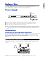 9
9
-
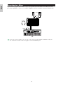 10
10
-
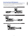 11
11
-
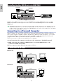 12
12
-
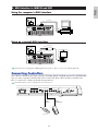 13
13
-
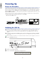 14
14
-
 15
15
-
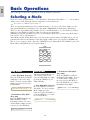 16
16
-
 17
17
-
 18
18
-
 19
19
-
 20
20
-
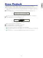 21
21
-
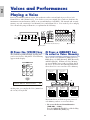 22
22
-
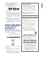 23
23
-
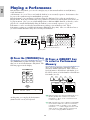 24
24
-
 25
25
-
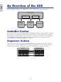 26
26
-
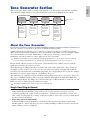 27
27
-
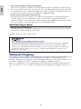 28
28
-
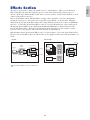 29
29
-
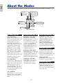 30
30
-
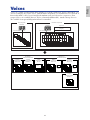 31
31
-
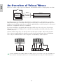 32
32
-
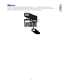 33
33
-
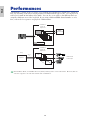 34
34
-
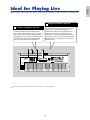 35
35
-
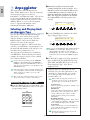 36
36
-
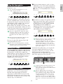 37
37
-
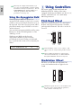 38
38
-
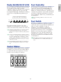 39
39
-
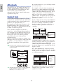 40
40
-
 41
41
-
 42
42
-
 43
43
-
 44
44
-
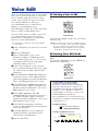 45
45
-
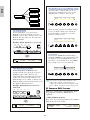 46
46
-
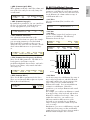 47
47
-
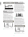 48
48
-
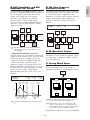 49
49
-
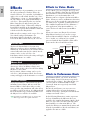 50
50
-
 51
51
-
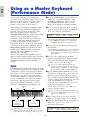 52
52
-
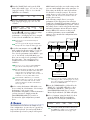 53
53
-
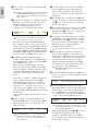 54
54
-
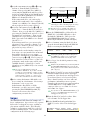 55
55
-
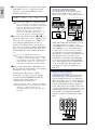 56
56
-
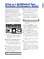 57
57
-
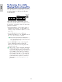 58
58
-
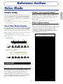 59
59
-
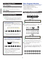 60
60
-
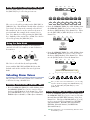 61
61
-
 62
62
-
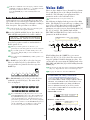 63
63
-
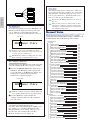 64
64
-
 65
65
-
 66
66
-
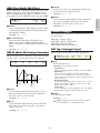 67
67
-
 68
68
-
 69
69
-
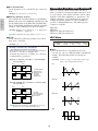 70
70
-
 71
71
-
 72
72
-
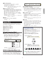 73
73
-
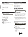 74
74
-
 75
75
-
 76
76
-
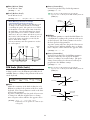 77
77
-
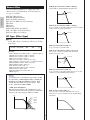 78
78
-
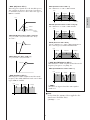 79
79
-
 80
80
-
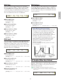 81
81
-
 82
82
-
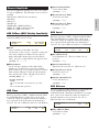 83
83
-
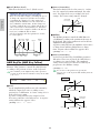 84
84
-
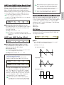 85
85
-
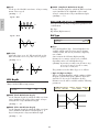 86
86
-
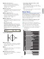 87
87
-
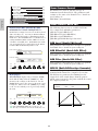 88
88
-
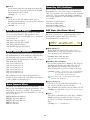 89
89
-
 90
90
-
 91
91
-
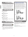 92
92
-
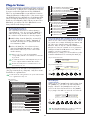 93
93
-
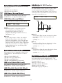 94
94
-
 95
95
-
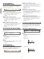 96
96
-
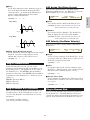 97
97
-
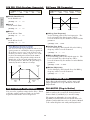 98
98
-
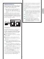 99
99
-
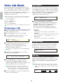 100
100
-
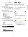 101
101
-
 102
102
-
 103
103
-
 104
104
-
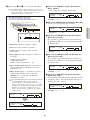 105
105
-
 106
106
-
 107
107
-
 108
108
-
 109
109
-
 110
110
-
 111
111
-
 112
112
-
 113
113
-
 114
114
-
 115
115
-
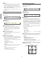 116
116
-
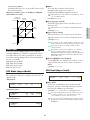 117
117
-
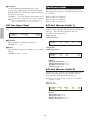 118
118
-
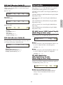 119
119
-
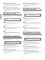 120
120
-
 121
121
-
 122
122
-
 123
123
-
 124
124
-
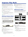 125
125
-
 126
126
-
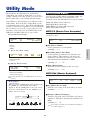 127
127
-
 128
128
-
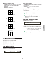 129
129
-
 130
130
-
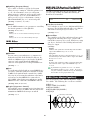 131
131
-
 132
132
-
 133
133
-
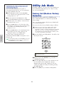 134
134
-
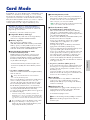 135
135
-
 136
136
-
 137
137
-
 138
138
-
 139
139
-
 140
140
-
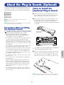 141
141
-
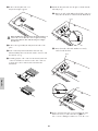 142
142
-
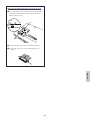 143
143
-
 144
144
-
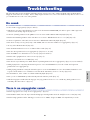 145
145
-
 146
146
-
 147
147
-
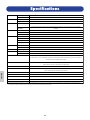 148
148
-
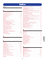 149
149
-
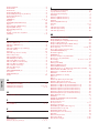 150
150
-
 151
151
-
 152
152
-
 153
153
-
 154
154
-
 155
155
-
 156
156


Yamaha S30 Manual de usuario
- Categoría
- Instrumentos musicales
- Tipo
- Manual de usuario
en otros idiomas
- français: Yamaha S30 Manuel utilisateur
- italiano: Yamaha S30 Manuale utente
- English: Yamaha S30 User manual
- Deutsch: Yamaha S30 Benutzerhandbuch
- русский: Yamaha S30 Руководство пользователя
- Nederlands: Yamaha S30 Handleiding
- português: Yamaha S30 Manual do usuário
- dansk: Yamaha S30 Brugermanual
- polski: Yamaha S30 Instrukcja obsługi
- čeština: Yamaha S30 Uživatelský manuál
- svenska: Yamaha S30 Användarmanual
- Türkçe: Yamaha S30 Kullanım kılavuzu
- suomi: Yamaha S30 Ohjekirja
- română: Yamaha S30 Manual de utilizare
Artículos relacionados
-
Yamaha Card Filer Manual de usuario
-
Yamaha CS6R El manual del propietario
-
-
Yamaha S08 El manual del propietario
-
-
-
Yamaha ES6 Manual de usuario
-
-
Yamaha PLG150-VL Manual de usuario
-
Otros documentos
-
Steinberg Retrologue Manual de usuario
-
Korg KROME EX Manual de usuario
-
Manhattan 153522 Manual de usuario
-
Manhattan 153546 Manual de usuario
-
Schneider Electric Power-Style QED Switchboards Connection to Motor Control Center El manual del propietario
-