
GRAZ
R1 99678 / 2012-02-21
Review these instructions completely before begin-
ning installation.
Questions - call customer service 855-DOLLE US
or 763-746-7830 - Monday - Friday 8:00-5:00 central.
Metric tools required.
Revise estas instrucciones en su totalidad antes de
iniciar la instalación.
Si tiene alguna pregunta, llame al servicio al cliente
al 855-DOLLE desde los EE.UU o al 763-746-7830 de
lunes a viernes de 8:00 a 5:00, hora central de los
EE.UU. Se necesitan herramientas métricas.
Mounting videos:
Vídeos de montaje:
www.dolleusa.com
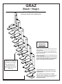
GRAZ
Black • Negro
Assembly instruction
Instrucciones de instalación
Local building codes vary. Please con-
sult with your local ofcials for specic
requirements.
Las normas de construcción locales
pueden variar. Póngase en contacto con
los técnicos locales para conocer los
requisitos locales
.
Above 30”: Railing
required (US code).
Por encima de 30”:
Se requiere una
barandilla (norma de
EE.UU.).
4” rule on open treads (US code).
Norma de 4” en escalones abier-
tos (norma de EE.UU).

2
Ø10 mm
9
60
7
K3 05003
K3 03010
290mm
11 7/16”
170mm
6 11/16”
290mm
11 7/16”
135mm
5 5/16”
K2 11440
K2 11430
K2-11470
K2-11450
K2-11410
K2-11400
K2-11610
M10 mm
Ø8 mmM8×6 mm
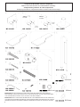
Components & Number of Each Component
Please check that all items are included before assembly
Componentes y Número de cada componente
Verique que todos los componentes estén incluidos antes de la entrega
IMPORTANT: DO NOT USE PARTS OTHER THAN THOSE INCLUDED WITH THE PRODUCT.
REPLACEMENT PARTS PURCHASED LOCALLY MUST BE METRIC. IN CASE PARTS HAVE BEEN
LOST OR DAMAGED CONTACT DOLLE USA INC. FOR REPLACEMENT.
IMPORTANTE: NO UTILICE PIEZAS DIFERENTES DE LAS SUMINISTRADAS CON EL PRODUCTO.
LAS PIEZAS DE RECAMBIO ADQUIRIDAS POR SEPARADO DEBEN SER MÉTRICAS. EN CASO DE
PÉRDIDA DE PIEZAS O DE PIEZAS DAÑADAS, PÓNGASE EN CONTACTO CON DOLLE USA INC
K3-10004 /
K3-10006

3
× 1
K2-32085
× 1
K1-32080
Ø47" Ø120cm
K1-32081
Ø55" Ø140cm
K2-32082
Ø63" Ø160cm
× 32
K1-32070
1 9/16"
40mm
39 3/8"
1000mm
× 1
K2-32520
× 26
K3-03031
M6×10×20mm
× 8
K3-08004
Ø10×70mm
× 2
K3-03024
M20mm
× 2
K3-04020
Ø20mm
× 1
K3-08002
Ø8x40
× 4
R1-63616
Ø10mm
× 14
K1-32097
× 26
K1-32096
× 1
K1-32046
× 1
K3-90001
Torx 25
Torx 30
PH2
3mm
13mm
30mm
4 mm
2.5mm
× 5
K1-01015
× 120
K3-10200
M6×5mm
× 92
K3-10100
Ø6×40mm
× 8
K3-10075
Ø8mm
× 8
K3-10175
Ø8×70mm
× 120
K3-10250
M6×16mm
× 30
K3-10125
Ø5×35mm
× 15
K3-10025
M5mm
× 15
K3-10000
M5×18mm
× 27
K3-05013
M6×6mm
R1-99934-001
30
33 34 35
50 5251 53 54 55 56 57
58 59 60 61 62 63
39 40 41 4238
64
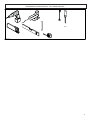
TOOLS REQUIRED - NOT SUPPLIED
HERRAMIENTAS NECESARIAS - NO SUMINISTRADAS

4
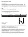
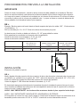
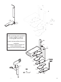
BEFORE INSTALLATION
IMPORTANT
Before starting installation, calculate the exact rise height of each step of the staircase. This is
done by measuring the distance from the lower oor to the upstairs oor measuring vertically
along the wall and then dividing by the number of rises. The number of rises is the same as the
number stair treads plus 1. The plus 1 is to consider distance of the last step of the staircase to the
upstairs oor.
BB =
Example: Top edge of oor to top edge of next oor: 102”, 12 rises (11 steps + 1).
102” divided by 12 = 8 ½”. This is the rise height per step.
The opening in the ceiling should not be less than 51 ¼” for straight ights of steps.
This is to ensure that walking up the steps is a comfortable experience.
Recommended rise height: 7
5
/
16
” to 8
1
/
16
”
Maximum rise height: 7
5
/
16
” to 8
1
/
16
”
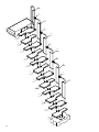
INSTALLATION
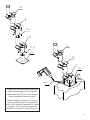
Top step element
AA =
Measure (from the top edge of the top oor) the calculated rise height plus the thickness of one
step (e.g. step 1
3
/
8
” thick + calculated rise height 8 ½” = 9
11
/
16
”).
This is the installation height for the top edge of the step support.
Please look at page 5 - BB: Is the calculated rise height e.g. 8 ½”.
It’s important to support the staircase temporarily during installation to prevent the weight of the
stairs to skew the riser measurements before fastening the lowest column support to the oor -
please see page 6.
NOTICE: VERY IMPORTANT - Staircase is to be assembled from the top oor down.
NOTICE: VERY IMPORTANT - WHEN MOUNTING OUTSIDE BANISTER
If the staircase is mounted with a turn, please note that the distance between the banister
elements may vary from 5
5
/
16
” to 13
9
/
16
” when mounting the outside banister.
No. of rises No. of steps:
One less than
no. of rises
X: Distance from bottom
step tread front to wall
Y: Vertical measurement of
wall - lower oor to upper
oor
12 11 63” 87
1
/
2
” – 106
1
/
4
”
13 12 68
1
/
8
” 94
1
/
2
” – 115”
X
Y
R1-99672-USA-01 / 10-03-2011

5
PROCEDIMIENTOS PREVIOS A LA INSTALACIÓN
IMPORTANTE
Antes de iniciar la instalación, calcule la altura exacta de cada peldaño de la escalera. Esta dis-
tancia se calcula midiendo verticalmente la distancia desde el piso inferior hasta el piso superior
a lo largo de la pared y dividiendo el resultado por el número de elevaciones. El número de eleva-
ciones es el mismo que el número de peldaños más 1, ya que se tiene en cuenta la distancia del
último peldaño de la escalera hasta el piso superior.
BB =
Ejemplo: Borde superior del suelo hasta el borde superior del piso de arriba: 102”, 12 elevaciones
(11 peldaños + 1).
259 cm dividido por 12 = 8 1/2”. Esta es la altura de elevación por paso.
La abertura en el techo no debe ser inferior a 51 1/4” para peldaños rectos.
Esto garantiza la comodidad a la hora de subir los peldaños.
Altura de elevación recomendada: 7 5/16” a 8 1/16”
Altura de elevación máxima: 7 5/16” a 8 1/16”
INSTALACIÓN
Elemento del peldaño superior
AA =
Medir (desde el borde superior del piso superior) la altura de elevación calculada más el grosor de
un peldaño (ej.: peldaño con un grosor de 1 3/8” + altura de elevación calculada 8 1/2” = 9 11/16”).
Esta es la altura de instalación del borde superior del soporte del peldaño.
Véase la página 5 - BB: Altura de elevación calculada, ej.: 8 1/2”
Es importante apoyar provisionalmente la escalera durante la instalación para evitar que el peso
de la escalera modique las mediciones del contrapeldaño antes de jar el soporte de la columna
inferior al suelo (véase la página 6).
AVISO - MUY IMPORTANTE: La escalera debe montarse desde el piso superior hacia abajo.
AVISO - MUY IMPORTANTE: MONTAJE DE LA BARANDILLA EXTERIOR
Si la escalera se monta con una vuelta, tenga en cuenta que la distancia entre los elementos de la
barandilla puede variar entre 5 5/16” a 13 9/16” cuando se monte la barandilla exterior.
Nº. de elevaciones Nº. de peldaños
Uno menos el n.º
de elevaciones
X: Distancia desde elstep
peldaño inferior frontal
a la pared
Y: Medida vertical de
la pared - piso inferior a
piso superior
12 11 63” 87
1
/
2
” – 106
1
/
4
”
13 12 68
1
/
8
” 94
1
/
2
” – 115”
X
Y
R1-99672-USA-01 / 10-03-2011

6
5-P
AA
AA
=
BB + 1
3
/8”
Ø 3/8”
Note
Installers responsibility to ensure
adequate backing material is in
place.
Nota
Los instaladores deben asegurar-
se de garantizar el montaje de un
soporte adecuado.

7
BB

8
Use support while building stairs.
(Support not supplied.)
Utilice un soporte mientras monta la es-
calera.
(Soporte no suministrado)

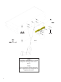
9
4-O
4-
B
B
C
D
4-K
5-N
5-N
B
B
C
D
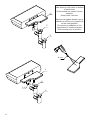
4-P
Ø 3/8”
Install base into oor with screws and
anchors depending on oor material.
Anchor sleeves (4-O) for concrete only.
Once completed, remove support.
Instale la base en el suelo con los tor-
nillos y anclajes según el material del
suelo. Sólo vainas de anclaje (4-O) para
hormigón. Una vez que se haya com-
pletado la instalación, retire el soporte.

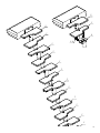
10
B
B
B
B
E
E
4-Q
Ø 3/16”
Mark where to drill holes on bottom
of each tread.
Screw treads into center column
supports.
Always use 4 screws.
Marque los lugares donde vaya a
taladrar los oricios en la parte infe-
rior de cada peldaño.
Enrosque los peldaños en los
soportes de la columna central.
Utilice siempre los 4 tornillos.

11
B
E
F
4-Q
E
F
F
F
F
F
F
F
F
F
F
F

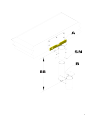
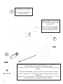
12
DD
2-L
2-J
2-M
DD
=
CC - 1
3
/8”
Ø 1/2”
Start banister on top tread.
Empiece la barandilla por el
peldaño superior.
1
2
3
Measure distance of top tread
and cut banister to appropriate
length - CC.
Mida la distancia del peldaño
superior y corte la barandilla a
la longitud adecuada - CC.
All banisters except the top, take the measurement of CC and reduce it by
1 3/8” (per DD) to cut handrail to the proper length.
Drill holes in tread 1 1/8” from front and 1 1/8” edge of tread and install top
banister.
En todas las barandillas, excepto la superior, se debe tomar la medida
de CC y reducirla en 1 3/8” (DD) para cortar el pasamanos a la longitud
adecuada.
Taladre oricios en el peldaño 1 1/8” desde la parte delantera y a 1 1/8” del
borde del peldaño, e instale la barandilla superior.
CC

13
H
I
G
E
F
F
F
F
H
J
M
I
H
I
G
E
F
F
F
F
CC2
DD2
H
H
I
G
E
F
F
F
F
H
J
M
I
H
I
G
E
F
F
F
F
CC2
DD2
H
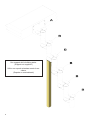
DD
28mm
1 1/8”
28mm
1 1/8”
Ø 1/2”
DD
=
CC - 1
3
/8”
Install remaining lower banisters
in same method as above.
Following DD instructions.
Instale las barandillas inferiores
restantes
siguiendo el mismo método de-
scrito anteriormente.
Siga las instrucciones para DD.
CC

14
H
H
H
H
H
I
I
I
I
I
G
E
F
F
F
F
F
F
F
F
F
F
F
-
 1
1
-
 2
2
-
 3
3
-
 4
4
-
 5
5
-
 6
6
-
 7
7
-
 8
8
-
 9
9
-
 10
10
-
 11
11
-
 12
12
-
 13
13
-
 14
14


en otros idiomas
- English: Dolle 68440 Installation guide
Artículos relacionados
-
Dolle 68300-2 Guía de instalación
-
-
-
-
-
-
-
-
-
