KitchenAid 720-0745B Instrucciones de operación
- Tipo
- Instrucciones de operación


Yo u can b e kille d o r s erious ly injure d if you do n t imme d iate ly
Yo u
ca n b e killed o r s e rio u s ly inju re d if you d on t
follow
All sa fety me ss a ges will te ll you what the pote ntia l ha za rd is , te ll you how to reduce the chance of injury, and tell you wha t ca n
ha ppe n if the ins tructions a re not followe d.
You r s afety a nd the s afety o f oth ers are ve ry im porta n t.
We ha ve provide d ma ny importa nt s afe ty mes sa ges in this manual a nd on your appliance . Always re a d and obe y all sa fety
me s sa ges .
This is the sa fe ty a le rt s ymbol.
This symbol a lerts you to potential hazards tha t can kill or hurt you and othe rs.
All s afe ty mes s ages will follow the s a fe ty a lert s ymbol a nd e ither the word DANGER or WARNING.
The se words mea n:
follo w in s truc tion s .
ins truc tio n s .
DAN G E R
WAR N IN G
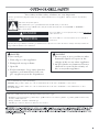
If yo u s me ll ga s :
1. S hu t o ff ga s to the app lian ce.
2. Extin gu is h a n y o pe n fla me .
3. Op en lid.
4. If o do r c on tinues , ke ep awa y from the
a pp lian c e a nd imm edia te ly ca ll yo ur
gas s u pp lier o r yo ur fire de p artme nt.
DANGER
WARNING
1. Do not s to re or u s e g as o lin e o r o the r
flam m ab le liq uids or vap ors in th e
vic in ity of th is o r an y o th e r a pp lia nc e.
2. An LP c ylind er no t co nn e cte d fo r u s e
s ha ll no t be s to red in th e vicin ity o f
th is or a ny oth er a pp lian c e.
Sta te of California Proposition 65 Wa rnings :
WARNING: This product contains one or more che micals known to the S ta te of Ca lifornia to ca us e cancer.
WARNING: This product contains one or more che micals known to the S ta te of Ca lifornia to ca us e birth de fects or other
reproductive harm.
In the Sta te of Mas sa chus e tts, the following insta lla tion ins tructions a pply:
n Insta lla tions a nd re pa irs mus t be performed by a qualifie d or lice ns e d contractor, plumbe r, or gas fitte r qua lifie d or lice ns e d by
the Sta te of Ma s s a chuse tts .
n If using a ball va lve , it s ha ll be a T-ha ndle type.
n A fle xible ga s connector, when us e d, mus t not e xce e d 3 fee t.

SAVE THES E INS TRUCTIONS
IMPORTANT S AFETY INSTRUCTIONS
WARNING: To re duce the ris k of fire , e lectrica l shock,
injury to pers ons , or da ma ge whe n us ing the outdoor cooking
ga s a pplia nce , follow ba s ic pre ca utions, including the
following:
n Do not ins ta ll portable or built-in outdoor cooking gas
a pplia nces in or on a re crea tiona l vehicle , porta ble traile r,
boa t or in a ny othe r moving ins tallation.
n Alwa ys mainta in minimum cle a ra nces from combustible
construction, se e Loca tion Require ments s ection.
n The outdoor cooking ga s a ppliance sha ll not be loca te d
under ove rhea d unprotected combus tible cons truction.
n This outdoor cooking ga s a pplia nce s hall be use d only
outdoors a nd s ha ll not be us e d in a building, gara ge , or any
othe r enclos e d are a .
n Ke e p a ny e le ctrica l s upply cord a nd fue l s upply hose a way
from a ny hea te d surfa ce s .
n Ke e p outdoor cooking gas a ppliance are a clear and fre e
from combustible mate ria ls, ga soline a nd other flammable
vapors and liquids .
n Do not obstruct the flow of combus tion a nd ve ntila tion air.
Ke e p the ventila tion ope nings of the cylinder e nclos ure fre e
a nd cle a r from de bris .
n Ope n the ca bine t door and inspe ct the gas cylinde r s upply
hos e before e a ch us e of the outdoor cooking gas
a pplia nce. If the hos e shows exce s s ive a bra s ion or we a r,
or is cut, it MUST be re pla ce d be fore using the outdoor
cooking ga s a ppliance. Conta ct your dea le r and us e only
re pla ceme nt hos e s s pe cifie d for use with the outdoor
cooking ga s a ppliance.
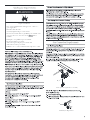
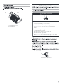
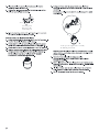
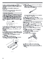
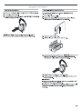
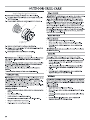
n Vis ua lly check the burner fla me s.
The y s hould be blue . S light
yellow tipping is normal for LP
ga s . The fla me s s hould be
a pproxima te ly 1" (2.5 cm) high.
n Che ck a nd cle a n burne r/ve nturi tube for ins e cts a nd inse ct
ne s t. A clogge d tube can le a d to fire unde r the outdoor
cooking ga s a ppliance.
n The LP gas s upply cylinder to be use d mus t be:
- cons tructed and ma rke d in accorda nce with the
Specifica tion for LP Gas Cylinde rs of the U.S . De pa rtment
of Tra ns portation (DOT) or the Nationa l Sta nda rd of
Ca na da , CAN/CS A-B339, Cylinde rs , Sphere s , a nd Tube s
for Tra nsportation of Da nge rous Goods; a nd Commiss ion.
- provided with a lis te d ove rfilling pre ve ntion de vice.
- provided with a cylinde r connection de vice compatible
with the conne ction for outdoor cooking ga s appliances .
n Always check conne ctions for le a ks ea ch time you conne ct
a nd dis conne ct the LP gas supply cylinde r. S e e
Insta lla tion Ins tructions s ection.
n Whe n the outdoor cooking gas a ppliance is not in us e , the
ga s must be turne d off a t the supply cylinde r.
n Stora ge of an outdoor cooking ga s appliance indoors is
pe rmiss ible only if the cylinde r is disconnecte d and
re move d from the outdoor cooking gas a ppliance.
n Cylinde rs mus t be store d outdoors a nd out of the re a ch of
children a nd mus t not be store d in a building, gara ge , or
a ny othe r enclose d a re a .
n The pre s s ure regula tor a nd hose as s e mbly supplied with
the outdoor cooking gas a ppliance mus t be use d. A
re pla cement pres s ure regula tor and hos e a s s e mbly
s pe cific to your model is a va ila ble from your outdoor
cooking gas a pplia nce dea le r.
n Ga s cylinde r mus t include a collar to prote ct the cylinde r
va lve .
n For a ppliance s de s igned to us e a CGA791 Connection:
Pla ce a dust ca p on cylinder valve outlet whene ver the
cylinder is not in us e . Only ins ta ll the type of dus t cap on
the cylinde r va lve outlet that is provided with the cylinde r
va lve . Other types of caps or plugs may res ult in le a ka ge
of propa ne .
If the following information is not followe d exa ctly, a fire
ca us ing dea th or s erious injury may occur.
n Do not s tore a s pa re LP gas cylinder unde r or ne a r this
outdoor cooking ga s appliance .
n Neve r fill the cylinder beyond 80 percent full.
1"
(2.5 c m )

n
n
n
n
n
n
n
n
n
n
n
n
n
n
n
n
n
n
n
n
n
n
n
n
n
n
n
WAR N IN G
WAR N IN G

FP
FP
FP
FP
FP
FP

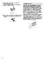
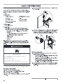
WAR N IN G
Explo s ion Hazard
Us e a ne w CS A In tern a tio na l a pp ro ved o u td o o r
g a s s u p p ly line .
Se c u re ly tig h te n a ll ga s co n n e ction s .
If co n n e cted to LP , h a ve a qu a lifie d p e rs o n ma ke s u re
g a s pres s u re do e s no t exce e d 14 wate r
c olu m n .
Exam p le s of a q u a lifie d pe rs o n inc lu de :
lice n s e d h e ating pe rs o n n el,
a utho rize d g a s c o m p a n y p e rs on n e l, an d
a utho rize d s e rvic e pe rs on n e l.
Fa ilu re to do s o ca n re s ult in d e a th , exp lo s io n , or fire .
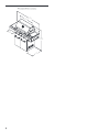
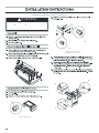
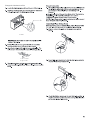
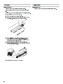
A. Gas pressure regulator/hose asse mbly
A. Tank tray locking bracket
A
A
In s ta ll a s h u t-off valve .

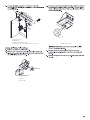
A. Loc king scre w
B. Bottom collar
C. Mounting hole
A. Tank tray locking bracket
A
C
B
A
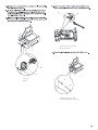
A. Gas supply line
B. S hutoff valve op en position
C. To grill
A
B
C

E
D
F
H
I
J
G
D

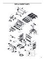
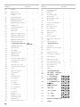
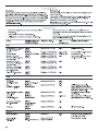
Part
Number
Part (description) Warranty
Coverage
Quantity
01 Main lid 3 1
02 Main lid screw 3 2
03 Tempe rature gauge
hous ing
1 1
04 Tempe rature gauge 1 1
05
Logo
1 1
06
Main lid handle seat, left
1 1
07 Main lid handle seat, right 1 1
08
Main lid handle tub e
09
Main lid b racke t, le ft
1 1
10
Main lid bracke t, right 1 1
11
12
Front baffle 1 1
13
Igniter junction wire 1 1
14
Main gas valve 3
4
15
Main control panel 3
1
16
1 5
17
1 4
18
19
Re gula tor, LP
1 1
20
Sid e burner ga s valve
1 1
21
Side manifold
3
1
22
Sid e burner fle x gas line A
1
1
23
1 1
24
Main manifold
1 1
25
1 2
26
27
28
1 1
29
Control knob
1 1
30
Bezel
1 4
31
32
33
Cart frame, front
34
Door magnet
35
36
Side shelf, le ft
1
1
37
Side s he lf front pane l, left
3 1
38
Rubbe r grommet 1 1
39
Sid e panel, le ft 1 1
Door hinge bracket 1 4
Swivel caster with brake 1 1
Swivel c a s te r 1 1
Cas te r 1 2
Bottom pa nel 1 1
45
Tank tray 1 1
46
Gas tank tray s lide
brac ket, left
1 1
47
Gas tank tray s lide
bracke t, right
1 1
48
49
50
51
52
Greas e box
53
54
Door handle s eat 1 4
55
Door handle tube 1 2
56
Door, left 3 1
57
Door, right
3 1
58
59
60
Electric igniter mod ule 1 1
61
Side panel, right 1 1
62
63
64
Bac k panel 1 1
65
66
Side burner control p a nel,
right
3 1
Sid e b urner b owl
ass e mbly
1 1
Sid e burner cooking grid
1 1
Sid e b urner lid
1 1
Sid e burner lid hinge rod
1 2
Main burner igniter wire A 1 1
Main burner igniter wire B 1 1
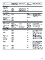
Part
Number
Part (description Warranty
Coverage
Quantity
Side burner orific e bracket
Warming ra c k
Door hinge
Sid e b urner
1 1
1 4
Main burner igniter wire C 1 1
Main burner igniter wire D 1 1
Main burner 10 4
Flame tamer 1 4
Cooking grid with hole 3 3
1 1
Sid e burner fle x gas line B 1 1
1 1
Side burner ignite r 1 1
Hook
1 6
Side burne r end cap
1 1
67
68
69
70
71
Burner p in as s embly
1 2
Side s he lf end cap
1 1
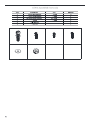
1 * &RQYHUVLRQNLW
72
76a
76b
76c
76d
76e
76f
with Lock
Quick Connector
assembly for NG unit
1
1
2
1
1
1
1 * * DV+ RVHZ LWK
P P 1 XW' ULYHU
+ H[ : UHQFK
P P : UHQFK
3KLOOLSV+ HDG6FUHZ
) ODW: DVKHU
1 * 5 HJXODWRUDVVHP EO\
2
1
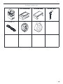
76g
40
41
42
43
44
Gas tank tra y s lide 1 2
Tank tray bolt
1 1
Gas tank tray block p iec e 1 1
Lighting rod 1 1
Lighting rod cover 1 1
3UHDVVHP EO\ KDUGZ DUH
SDFN
0 DQXDO
1
1
77
78
1
1
0 DLQEXUQHUERZ O
DVVHP EO\
1 RQ
UHSODFHDEOH
1
%XUQHUSLQDVVHP EO\
73
74
Eye b olt
7DQNKHDWVKLHOGSDQHO
1 1
75a
76
6LGHEXUQHU1 * RULILFHSDFN
1 1
1
1
75
6LGHEXUQHU1 * RULILFH
1 1

¹⁄₄ ¹⁄₄
⁵⁄₃₂ ⁵⁄₃₂
⁵⁄₃₂ ⁵⁄₃₂
⁵⁄₃₂
⁵⁄₃₂


A. Side burner s crews
c
m m
WAR N IN G
c c
A
A.
Grill control panel screw
B. Grill side p anel screws
A
B
A
B
C

A.
Bezel
B. Valve
A. Electrical plug from grill
B. Electrical plug from side burner
A
B
A
B
A. Side burne r orifice bracket.
B. Sid e burne r tube
A
B

A. Side shelf screws
A. Grill side panel sc rews
B. Grill c ontrol pane l scre w
A
B
A

A. Warming shelf brackets
B. Warming s he lf
B
A
A. Tank tray locking bracket
WAR N IN G
Explo s ion Ha za rd
Se c u re ly tig h te n a ll g as c on n e ction s .
If co n n e cted to LP , ha ve a qu a lifie d pe rs o n m a ke s ure
g a s pres s u re do e s no t exce e d 14 (36 c m ) wa te r
c olu m n .
Exam p le s of a q u a lifie d pe rs on inc lu de :
lic en s e d h e ating pe rs o n n el,
a utho rize d g a s c o m p a n y p e rs on n e l, an d
a utho rize d s e rvic e pe rs on n e l.
Fa ilu re to do s o ca n re s ult in d e a th , exp lo s io n , or fire.
A

A. Locking screw
B. Bottom collar
C. Mounting hole
A
C
B
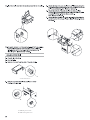
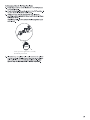
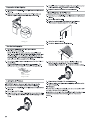
A. Gas press ure regulator/hose asse mbly
B. 20 lb LP gas fuel tank
A
B

A. Gas pressure regulator/hose assembly
B. 20 lb LP gas fuel tank
A
B

n
n
n
n
n
n
n
n
n
n
n
n
n
n
n
n
n
n
WAR N IN G
Explo s ion Hazard
Us e a ne w CS A In tern a tio na l a pp ro ved o u td o o r
g a s s u p p ly line .
Se c u re ly tig h te n a ll ga s co n n e ction s .
Fa ilu re to do s o ca n re s ult in d e a th , exp lo s io n , or fire .
In s ta ll a s h u t-off valve .

A.
Le ft side panel
B. Manifold
C. 10 ft. (3.0 m) PVC gas hose
D. Natural gas press ure regulator/hose asse mbly
A. Scre w
B. Cotter clip
A
B
C
D
A. Main burner orifice
A
A
B

A. Orifice
A. Close d valve
B. Open valve
A
A
B
Change the side burner orifice

¹⁄₈ ¹⁄₄
A. Screw
1" (2.5 c m )
A
A. Air s hutter adjustment screw
A. Valve stem
B. Small flat-blade scre wdriver
C. P lie rs
A
A
B
C

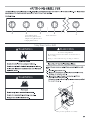
A. Left grill b urne r knob
B. Le ft-center grill burner knob
C. Right-center grill burne r knob
D. Right grill burner knob
E. Side burne r knob
E
D
C
B
A
WAR N IN G
WAR N IN G
A. Gas pressure regulator/hose assembly
WAR N IN G
Fo o d Po is o n in g Ha za rd
Do n ot le t foo d s it for m o re tha n on e ho u r b e fo re or
a fter c o o kin g .
Doin g s o ca n re s ult in foo d po is on ing or s ic kn e s s .
A

A. Drip pan
A. Closed valve
B. Open valve
A
A
B


n
n
n
n
n
n
n
n
n
n
n
n
n
n
n
WARNIN G
Fo o d Po is o n ing Hazard
Do n o t let fo o d s it fo r mo re th an o n e ho u r b efo re o r
a fte r c oo kin g .
Doin g s o c a n re s u lt in fo o d po is o n in g or s ic kne s s .

n
n
n
n
n


A. AA size battery
B. Igniter c ap
A
B
n
n
n
n
n
n
n
n
n
n
n
n
n
n
n
n

n
n
n
n
n
A. 2 screws
A. Burner/orifice connection
A
A

n
n
n
n
n
n
n
n
n
n
n
n
n
n

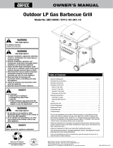
(Model #720/730-0745B)
n
n
n
n
n
n
n
n
n
n

Re p air or replacement of defective parts is your exclus ive remedy
All consumer returns, parts orders, gene ral questions , and troub leshooting assistanc e can be acquired by calling 1-877-373-2301.

-
 1
1
-
 2
2
-
 3
3
-
 4
4
-
 5
5
-
 6
6
-
 7
7
-
 8
8
-
 9
9
-
 10
10
-
 11
11
-
 12
12
-
 13
13
-
 14
14
-
 15
15
-
 16
16
-
 17
17
-
 18
18
-
 19
19
-
 20
20
-
 21
21
-
 22
22
-
 23
23
-
 24
24
-
 25
25
-
 26
26
-
 27
27
-
 28
28
-
 29
29
-
 30
30
-
 31
31
-
 32
32
-
 33
33
-
 34
34


KitchenAid 720-0745B Instrucciones de operación
- Tipo
- Instrucciones de operación
en otros idiomas
Otros documentos
-
MOTO GUZZI 850-T El manual del propietario
-
HQ AT20 Manual de usuario
-
Central Pneumatic 60637 Air Compressor El manual del propietario
-
Cessna 150 1969 El manual del propietario
-
Velleman PEM10D2 Manual de usuario
-
 Altec Lansing 4100 Manual de usuario
-
-
 Tivax STB-T9 Manual de usuario
-
Amana TGP305TT2 El manual del propietario
-
 Backyard GBC1305W El manual del propietario


