Cessna 150 1969 El manual del propietario
- Categoría
- Juguetes
- Tipo
- El manual del propietario

,.
..
1
~ee~a
,
.......
~
L
__j
...
...
...
MORE
PEOPLE
BUY
AND
Fl
Y
CESSNA
AIRPLANES
THAN
ANY
OTHER
MAKE
1969
WORLD'S
LARGEST
PRO-
DUCER
OF
GENERAL
AVIATION
AIRCRAFT
SINCE
1956
OWNER'S
MANUAL

PERFORMANCE
-
SPECIFICATIONS
Mo
del
150
*
GROSS WEIGHT . . . . .
SPEED:
Top
Sp
ee
d
at
Sea
Le
ve
l
Cruise,
75% Power
at
7000 ft
RANGE:
Cruise,
75%
Power
at
7000 ft
22. 5
Gallons
, No R
ese
rv
e
Cruise
, 75% Power at 7000 ft
Long
Range
Versi
on,
35. 0
Gallons
Optimum
Ra
nge
at
10, 000
ft
.
22. 5
Gall
o
ns
, No Rese
rv
e
Optimum
Ra
nge
at
10, 000
ft
.
Long Ra
nge
Ve
rsi
on, 35. 0
Gallons
RATE
OF
CLIMB
AT
SEA
LEVEL
SERVICE CEILING
TAKE-OFF:
Ground
Run .
To
tal
Di
stance
O
ve
r
50-
Ft
Obs tac le.
LANDING:
Landing
Roll . . . . . . . . . . .
To
ta
l
Distan
ce
Over
5
0-Ft
O
bst
acl
e.
EMPTY
WEIGHT:
(Approximate)
With
Stand
a
rd
Fuel
Ta
nks
. .
With Long Range
Fu
el T
anks
.
BAGGAGE
.........
. .
WING
LOADING:
Pounds
/ Sq Foot
POWER LOADING:
Pounds
/
HP
FUE
L CAPACITY:
Total
(Stand
ar
d
Tanks)
. .
Total
(Long
Ra
nge
Tanks)
.
OIL
CAPACITY
:
(Total).
. . .
PROPELLER
:
Fixed
Pit
ch
(Diameter)
ENGINE:
Continental
Engine . .
100
rated
HP
at
2750 RPM
STANDARD
AND
TRAINER COMMUTER
1600
lbs
122 mph
117 mph
475
mi
4.
i'
hrs
117 mph
725
mi
6. 2
hrs
117 mph
565
mi
6. 1
hrs
93 mph
880
mi
9. 4
hrs
93
mph
670 fpm
12,
650 ft
7
35
ft
1385 ft
4
45
ft
107 5 ft
Standard
Tr
ai
ner
975 lbs f0051bs
980
lbs
1010
lbs
120
lbs
10. 2
16.0
26
ga
l.
38
ga
l.
6
qts
69 inches
0-200-A
1600 lbs
1
22
mph
117 mph
475
mi
4. 1
hrs
117 mph
725
mi
6. 2
hrs
117 mph
565
mi
6. 1
hrs
93
mph
880
mi
9.
4
hrs
93 mph
670 fpm
12,
65
0 ft
7
35
ft
1385
ft
445 ft
1075 ft
1060
lbs
1065
lbs
120
lb
s
10. 2
16. 0
26
ga
l.
38
ga
l.
6
qts
69
inches
0-200-A
*
Th
is
ma
nual
cov
e
rs
op
eration
of
t
he
M
odel
150
wh
ich
is
certificated
as
Mo
del
150
J
under
FAA
Type
C
ert
ific
ate
No
. 3A
19
.
The
manual
a
lso
covers
operat
ion
of
the
Mod
el
F150
wh
ich
is
ce
r
tificated
as
Mode
l
F150J
under
French
T
yp
e
Cert
if
icat
e No.
38/3
and
F
AA
Type
Ce
rtificate No. Al3EU.
The
M
odel
flSO
.
manufac
tu
r
ed
by
Reims
Avia
t
ion
S.A.
.
Reims
(Marne).
Fra
nce
.
is
identical to
the
150
except
that
it
is
po
w
ered
by
an
0
-2
00
-A
engine
manulactured
under
l
icense
by
Roll
s R
oyce
.
Crewe.
England
.
All
1
50
i
nforma
tion
in
this
manual
perta
ins to
the
f
150
as
we
ll.
0624-13
COPYRIGHT
rs>
1967
Cessna Aircraft Company
Wichita. Kansas
USA

CONGRATULATIONS.
. . . .
Welcome
to
the
ranks
of
C
ess
na
owners!
Your
Cessna
has
been
designed
and
constructed
to
give you the
most
in
performance,
economy, and
com-
fort.
It
is
our
desire
that
you
will
find flying
it,
eitl)er
for
business
or
pleasure,
a
pleasant
and
profitable
experience.
This
Owner's
Manual
has
been
prepared
as
a guide
to
he
lp
you
get
the
mo
st
pleasure
and
utility
from
your
Model 150.
It
contains
information
about
your
Cessna's
equipment,
operating
procedures,
and
performance;
and
suggestions
for
its
serv
icing
and
care.
We
urge
you
to
read
it
from
cover
to
cover,
and
to
r efer
to
it
frequently.
Our
interest
in
your
flying
pleasure
has
not
ceased
with
your
purchase
of
a
Cessna.
World-wide,
the
Cessna
Dealer
Organization
backed
by
the
Cessna
Service
Department
stands
ready
to
serve
you. The following
services
are
offered
by
most
Cessna
Dealers:
FACTORY TRAINED PERSONNEL
to
provide
you with
courteous
expert
service.
·
FACTORY APPROVED SERVICE EQUIPMENT
to
provide
you
with
the
most
efficient
and
accurate
workmanship
possible.
A STOCK
OF
GENUINE CESSNA SERVICE PARTS on
hand
when you
need
them.
THE
LATEST AUTHORITATIVE INFORMATION FOR
SERV-
ICING CESSNA AIRPLANES,
since
Cessna
Dealers
have
all
of the
Service
Manuals and
Parts
Catalogs,
kept
current
by
Service
Letters
and
Service
News L
etters,
publish
ed
by
Cessna
Aircraft
Company.
We
urge
all
Cessna
owners
to
use
the
Cessna
Dealer
Organization
to
the
full
est.
A
current
Cessna
Dealer
Director
y
accompanies
your
new
airplane.
The
Directory
is
revised
frequently
,
and
a
current
copy
can
be
obtained
from
your
Cessna
Dealer.
Make
your
Directory
one
of
your
c
ross-c
ountry
flight planning
aids;
a
warm
welcome
awaits
you
at
every
Cessna
Dealer.

ii
• Maximum h
eig
ht of
ai
rplane with
nose
gear
depressed
and
an optional flashing
beacon
installed.
OV•rall
l
engt
h
of
ai
rplan
e with
optional
bulle
t -
shaped
propeller spinner.
When
standard propeller
spiMer
Is
I
nstall
e
d,
length Is 23'.
,
77\l
'-.,;:.
~----
""""-
"--:
~;:;,~'_/
•8
'.
7 Y,"
MAX.
~=::::-
---:
1
1
PRINCIPAL
DIMENSIONS
11<·
~--
-
--
-
--
-----32'-BYi'"--
-
----
---
----i

TABLE
OF
CONTENTS
================================
========
==
====
Pag
e
==
SECTION
-
OPERATING
CHECK
LIST
..............
1-1
SECTION
II -
DESCRIPTION
AND
OPERATING
DETAILS
...................... 2-1
SECTION
Ill
-
OPERATING
LIMITATIONS
............. 3-1
SECTION
IV-
CARE
OF
THE
AIRPLANE
............ 4 -1
OWNER
FOLLOW-UP
SYSTEM.
...........................
4-9
SECTION
V -
OPERATIONAL
DATA
...................... 5 -1
SECTION
VI
-
OPT
I
ONAL
SYSTEMS
...................... 6-1
ALPHABETICAL
INDEX
........................................
tn
d
ex-
1
Thls
manual
describ
es
the
operatio
n
and
pe
rformance
of
th
e S
tandard
Model 150,
th
e
Tr
ainer
and
the
Commuter.
Equip-
men
t d
esc
rib
ed
as
"Optional"
de
notes
tha
t
the
s
ub
ject
equipme
nt
is
op
t
ional
on the
Standard
airplane.
Much of
this
equipme
nt
is
s
tandard
on
the
Tr
aine
r
and
Commut
e
r.
iii

EXTERIOR
INSPECTION
CD
<·>
l\Jrn on
master
switch
and
check
fuel quantity
lndJca.tors,
then
turn
master
1
wit
ch
"O
FF.
"
(b) Check Ignition swHch
"O
FF.
"
(c
) C
heck
fuel
valve
handle
"ON."
(d)
Rem
ove
con
lr
ol
wheel
l
oc
k.
CD
(a) Re
mo
ve
rudder
gust
lock, U
11'18lalled.
(b) O
l•coMec
t ta.II
ti
e-down.
0 (a) R
cmo>e
gust
lock,
U
Insta
lled.
©
(a) Di
sconnect
wing
tie-down.
N 0
TE
Visually
check
fu
el
Hiler
ca
ps,
lnspecllon
pla.J.es, and
gene
rill
a.ircr:i..fl
cond
1tl
on
d
uring
walk-
aro
und
ln
specllon.
If
night
flight
ls
pl:lllned,
chec
k
operatio
n
of
all
lights,
and make
sure
a
fla
shll,h
t Is aval
lable.
four
seconds
lo
clear
fuel
st
r
ainer
of
possible
wat
er
and
sediment.
Check
st
ra
iner
drain
closed.
U
water
la
o
bserved,
there
ts
a
possi
-
bilit
y
that
the
wi
ng tank
sumps
contain
waler.
T
hus,
th
e
wing
tank
sump
drain
plugs
and
fuel
line
drain
plug
should
be
removed
to
check
for
presence
of
water.
(c)
Check
propeller
and
spinne
r
for
nicks
and
security
.
(d)
Check
ca
rbJ
retor
air
filter
for
resLrlctlons
by
dust
or
othe
r
foreign
ma
tter
.
(e)
Check
n
ouwheel
s
trut
and
ti
re
fo
r
prOl!er
tn
-
fbllon.
(0
DlscoMect
nose
t
ie
-
down.
Same as ©
(b)
(c)
Ch
ec
k m
ain
wheel
tire
for
proper
inlla
tl
on.
Inspe
ct
airspeed
s
tatic
source
hole
on
side
of
fus
elage
for
st
oppag
e (lcrt
side
on
ly
).
CD
<·>
R
emOYe
pilot
tu
be
cover,
if
installed,
and
check
pilot
tu
be openi
ng
for
stop
page.
CD
<
•>
Check
olJ
level.
Do
not
opera
te
with
less
than
4
quarts.
FUI for
extended
Olghts.
(b)
Before
flr~l
night
of
day
a
nd
alter
each
re-
(;\
f
ue
li
ng, pu
l1
out
st
ra
iner
drain
knob ror
about
\..V
(b)
Check
fu
el
tank
vent opening
for
stoppage.
(c)
Check
stall
wa.rnin& v
ent
opening
for
stoppage.
Same
as
(!)
Fi
gure
1-1.
iv

Section
I
•
..
,..--~~~~~~~~~~~-
.t?r
....
._
----~~~~....,...~~~~
~
~~~~~~~~~~~~~~tnr
........ _
OPERATING
CHECK
LIST
Cne
of
the
first
steps
in
obtain
ing
the
utmost
perfo
r
mance,
service,
and
flying
enjoyment
from
your
Cessna
is
to
familiarize
your
seli
with
your
airp
l
ane
's equi
pment,
systems,
and
contro
ls .
This
can
best
be
done by
r
eviewing
this
equipment
while
sitting
in
the
airp
l
ane.
Th
ose
items
whose
function and
ope
rati
on
are
not
obvi
ous
are
cove
r
ed
in
Section
II.
Section
I
li
sts,
in
Pil
ot's
Check
L
ist
form,
the
steps
necessary
to
operate
your
airplane
efficiently
and
safely.
It
is not a
check
list
in
its
tru
e
form
as
it
is
conside
rably
l
onger,
but it
does
cover
briefly
all
of
the
points
that
you
sho
uld
know
for
a
typical
flight.
The
flig
ht
and
ope
r
ationa
l
characteristics
of
your
airp
l
ane
are
no
rma
l
in
a
ll
r
es
pe
c
ts.
There
ar
e no un
conven
ti
ona
l c
hara
cteristics
or
operations
that
need
to
be
maste
r
ed.
A
ll
contro
ls
resp
ond
in
the
nor
ma
l way
within
the
en
ti
re
range
of
ope
rati
on. All
airspeeds
mentioned
in
Sections
I and
II
are
ind
i
cated
airspeeds.
Corresponding
calibrated
ai
rsp
eeds
may
be
obtained
from
the
Airspeed
Correction
Table
in
Section
V.
BEFORE
ENTERING
THE
AIRPLANE.
{l ) M
ake
an
exterior
insp
ection
in
accordance
with
figure
1- 1.
BEFORE
STARTING
THE
ENGINE.
(1)
Seats
and
Seat
Belts
- -
Adjust
and
lock.
(2)
Fue
l
Valv
e Handle
--
"
ON."
(3)
Brakes
- -
Test
and
set.
(4)
Radios
and
Flashing
Beacon
--
"OFF
. "
STARTING
THE
ENGINE.
{l)
Carbur
etor
H
eat
--
Cold
.
(2)
Mixture
--
Rich.
1- 1

(3)
Primer
--
As
requir
e
d.
(4)
Throttle
- -
Op
en
1/
4".
(5)
Master
Switch
--
"
ON."
(6)
Propeller
Area
- - Cl
ear
.
(7) I
gnitio
n
Swit
ch --
"S
TART'
'
(release
when
engine
starts).
(8)
Oil
Pr
ess
ur
e
--
Check.
BEFORE
TAKE-OFF.
(1)
Cab
in Doo
rs
- -
La
tche
d.
(2)
Fli
g
ht
Cont
rols
--
Check
.
(3)
Trim
Tab
-- "
TAKE-OFF"
setting.
(4)
Thr
o
ttle
Setting
-- 1700
RPM.
(5)
Engine
I
nstruments
--
Within
gr
een
ar
c.
(6)
Suction
Gage
- -
Che
ck (4. 6
to
5. 4
inches
of
mercu
r
y)
.
(7)
Carb
u
retor
H
eat
--
Check
ope
r
ation.
(8)
Magnet
os --
Check
(75
RPM
maximum
differential
between
magnetos
.)
(9)
Flight
Instrum
ents
and
Ra
dio
s --
Se
t.
(10)
Opt
ion
al
Wing
Lev
eler
--
"
OFF
. "
TAKE-OFF.
NORMAL
TAKE
-
OFF
.
(1) Wing
Flaps
--
Up.
(2)
Carbureto
r H
eat
--
Cold.
(3)
Throttle
-
Fu
ll
"
OP
EN."
(4)
Elevator
Co
n
tro
l
--
Lift
nose
wheel
at
50
MPH.
(5) C
lim
b
Speed
--
73
MP
H
until
all
obstacles
are
cl
eared,
then
set
up c
li
mb
speed
as
shown
in
"N
O
RMAL
CL
IMB"
paragraph.
MAXIMUM
PERFO
RM
ANCE
TAKE-O
FF
.
(1)
Win
g
Flaps
--
Up.
(2)
Ca
rbur
et
or
H
eat
--
Col
d.
(3)
Brakes
--
Hold.
(4)
Thr
ot
tl
e
--
F
ull
"
OPEN."
(5)
Brakes
--
Rel
ease
.
(6)
Elevator
Contro
l
--
Sli
g
htly
ta
il
low.
(7)
Climb
Speed
- -
64
MPH (with
obstacles
ahead)
.
CLIMB.
NORMAL
CLIMB
.
(1)
Air
Sp
ee
d - - 75
to
80
MPH.
1
-2

(2) P
ower
--
Full
throttle
..
(3)
Mixture
--
Rich
(unless
engine
is
rou
gh).
MA
XIMUM PERFORMANCE
CLIMB
.
(1)
Air
Speed
--
73
MPH.
(2) Power - -
Full
throttle.
(3)
Mixture
- -
Rich
(unless
engine
is
r ough).
CRUISING.
(1)
Power
- - 2000
lo
2750
RPM
.
(2)
Elevator
Trim
--
Adjust.
(3) Mi
xture
--
Lean
to
maximum
RPM.
BEFORE
LANDING.
(1)
Mixture
- -
Rich.
(2)
Carburetor
Heat
--
Apply
full
heat
be
fore
closin
g
throttle
.
(3)
Airspeed
- -
65
to
75
MPH.
(4) Wing
Flaps
- -
As
desired
below
100
MPH.
(5)
Airspeed
- - 60 to 70
MPH
(flaps
extend
ed).
NORMAL
LANDING
.
(1)
Touch
Down - -
Main
wheels
first
.
(2)
Landin
g
Roll
- -
Lower
nose
wheel
ge
ntly.
(3)
Brakin
g - -
Minimum
re
quir
ed.
AFTER
LANDING.
(1) Wing
Flaps
--
Up.
(2)
Carburetor
Heat
- - Cold.
SECURE
AIRCRAFT.
(1)
Mixtur
e - -
Idle
cut-off.
(2) All
Switches
-- Off.
(3)
Parkin
g
Brake
--
Set.
(4)
Contr
ol Lo
ck
--
Ins
talled.
1-
3

INSTRUMENT
PANEL
2 3 4 5 6 7 8 9
10
11
12
I.
Turn
Coordinator
(Opl
.)
2.
Air
speed
tnd1
c
ator
3.
Dir
ec
ti
o
nal
Cyro
(
Opt.
)
4 .
Gyro
H oriz.on
(Opt.
)
5.
Clock
(Opt.
)
6.
Aircraft
Registratton Number
7.
Vert
ica
l
Speed
l
ndlcuor
(Opt.)
8.
Altlmeler
9.
Muk
er
Beacon
L
ights
/
Radio
Tran
sm1tt
r>r
St!lector Switch
I 0.
Omni
C
ou
rse I
ndica
tor
(Op
t. )
11. Rc:ir V
ie
w M
lr
ror (
Opt.)
l 2.
Rad
ios
(
Opt.
)
1-4
13.
Ta
ch
omet
er
14.
Le!t
Fuel
Quanttty
Ind
icato
r
IS
.
Bea
ring lndicator
(Opt.)
16.
Riaht F
uel
Quantity Ind
ica
tor
17.
Sucllon
Ca~e
(Opt.)
18.
A
mmeter
19.
Oil
Temperature
Ga
ge
20.
011
Pressu
re
G;ige
21.
Ma
p Compar
tment
22.
Cabin
Atr
and H
eat
Control
Knobs
23.
W
I~
flap
Swi
tch
24.
Ciga
r
Ligh
t
er
(Opt.)
25.
Mixt
ure
Control
Knob
Fi
g
ure
2-1.
13 14
15
16
17
26.
Wing
Le
vele
r
Co
ntrol
Kn
ob
(Opt.)
27. Mic r
ophone
(
Opt.
)
28.
Throttle
29.
El
evator
Tnm
Control Wheel
30.
Carburetor
Heat Control
Kn
ob
31.
Ele
c
tr
ical
S
wll
ch
es
32. Fuses
33.
Rad
io
Dial Lighl
Rheos
tat
34.
Altern2tor
Circuit
Break.er
3$.
lgn1tlon. 'Starter
Switch
36.
Master
Switch
37.
En.gtne
Primer
38. Parking
Brake
Kn
ob

Se
c
tion
II
brr
111:====================~~~~~~~~~~-·brr
.......
_
DESCRIPTION
AND
OPERATING
DETAILS
The
fo
ll
owing
paragraphs
describe
th
e
systems
an
d e
quipment
wh
ose
func
ti
on
and
operation
is not
obvious
when
sitting
in
th
e
airplane.
Th
is
section
al
so
covers
in
som
e
what
gr
ea
ter
detail
some
of
the
items
listed
in
Check
List
form
in
Section
I
that
requir
e
further
exp
lanatio
n.
FUEL
SYSTEM.
Fu
el
is
supplied
to
the
engine
from
two
tanks
,
one
in
each
win
g.
From
thes e
tanks
,
fuel
flows by gr
avity
thr ough a
fuel
shut
off
va
lve
an
d
fuel
strainer
to the
ca
rbur
eto
r.
R
efe
r to
figure
2-2
for fuel
quantity
data
.
For
fu
el
syste
m
service
i
nforma
ti
on,
refer
to
Lu
b
ri
ca
ti
on
and
Servi
c
in
g
Pr
oced
ur
es
in
Sect
i
on
IV.
FUEL
STRAINER
DRAIN
KNOB
.
Refer to fuel
strainer
serv
ic
in
g
procedure,
Sec
ti
on
IV.
FUEL
QUANTITY
DATA
(U.S.
GALLONS)
USAB
LE
F
UEL
UNUSABLE
TOTAL
TANKS ALL
FLIGHT
FUEL
FUEL
COND
ITIO
NS
VOLUME
TWO,
STANDARD WING
22. 5 3. 5
26.0
{13
GAL. EACH)
TWO, LONG
RA
GE WING
35.0
3. 0 38. 0
(19 GAL. EACH)
F
igu
re
2- 2.
2-1

VENT
2-2
llnllllt;~jjlj~~~llll~llll~l~ll~l
fjjj~~;~ill
1~~l1
~11lli
LEFT
FUEL
TANK
!W;;':
i
:
!!
!
!!;!!!!
!!!!~ll!lllllllllllilill!illlilllilllll
RI
GHT
FUEL
TANK
°
FUEL
0
FUE
L
SHUTOFF
22.s GA
lS
VALVE
O
N
~
CODE
..._._.,.._
o
,_
•-•
...,
o !;;;;;;;;;;;;!
FUEL
SUPPL
Y
FUEL
SYSTEM
···
·SCHEMATIC
····
CARBURETOR
TO
ENGINE
CYLINDERS
....
Figu
r e 2- 3.
c:::::J
VENT
MEC
HA
NI
CAL
LINKAGE
THROT
TL
E
...
--1-rfl
......
~
<
......
------
~
MIXTURE
CO
NTROL
KNOB

ELECTRICAL SYSTEM.
Electrical
energy
is
supplied
by a 14-volt,
direct-current
sys
tem
p
owered
by
an engine
-driv
en
alternator
(see
figure
2-4
). A
12-
vo
lt
battery
is
located
on the
ri
ght,
forwar
d
side
of the
firewall
just
inside
the
cowl
access
doo
r.
Power
is
supplied through a sing
le
bus
bar
; a
mas
t
er
switc
h con
tr
ols
this
power to
all
c
ir
cuits,
except
the en
gi
ne ignition
sys-
t
em,
optional clock and optional flight
hour
recorder
(operative
only wh
en
the engine
is
o
peratin
g).
AMMETER.
The amm
ete
r indi
ca
t
es
the fl
ow
of
current,
in
amper
es
,
from
the
alte
rn
ato
r to
th
e
battery
or
fr
om
the b
atte
r y
to
the a
irc
r aft el
ectrical
system.
Wh
en the engine is ope
ratin
g and the
maste
r switch is
"ON,"
the
am
m
ete
r indicat
es
the
chargi
ng
rate
applied to the
batt
e
ry
.
In
the
event
the a
lt
e
rn
ator
is
not
fu
nc
ti
oning or the el
ect
rical
l
oa
d
exceeds
th
e
output of the a
lt
e
rn
ator , the am
meter
indi
cates
the
di
sc
har
ge r ate of the
bat
tery
.
FUSES
AND
CIRCUIT BREAKERS.
Fuses
on
the left lo;.ver po
rti
on
of the
in
st
rum
e
nt
panel
protect
the
ma
jori
ty of el
ectrica
l c
ircuits
in the
airp
lane. Labeling bel
ow
eac
h fu
se
r
etainer
indi
cates
the c
ir
cuits
pr
ot
ec
ted by the fu
ses
. Fu
se
ca
pa
city is
shown on
each
fuse
reta
iner
cap.
Fuses
are
r
emove
d by
pressing
the
fuse r
etai
ne
rs
inward and rotating them
counterc
lockwise until th
ey
di
s-
engage. The faully fuse may then be lifted
ou
t and
repla
ce
d.
Spare
fuses
are h
eld
in a c
lip
on the i
nsid
e of the map
co
mpartment
doo
r.
NOTE
A
special
"SLO-BLO"
fuse
protects
the wing flaps
ci
rcuit.
lf
this
fuse
is
replaced,
care
shou
ld
be
tak
en
to
assure
that
the
rep
l
acement
fuse
is
of the proper type and
ca
pa-
ci
ty
. A "S
LO-BLO"
fuse
is
identified by an integr ally
mounted
spri
ng en
ci
rc
ling the
fus
e element.
Tw
o ad
diti
onal
fuses
are
l
ocaled
adjace
nt
to
the
bat
ter
y;
one
fuse
pro-
t
ects
the
battery
con
ta
ct
or
closing
circu
it
, and the oth
er
fuse
protects
the
optional clock and optional flig
ht
h
our
r
eco
rd
er
c
ir
c
uits.
The
airp
lane u
til
i
zes
thre
e c
ircuil
·
breake
rs f
or
circ
uit
protectio
n. A
"p
us
h-
to
-r
ese
t"
c
ir
cuit
br
eaker
(labeled "
GE
N"
)
is
l
ocated
on the left
si
de
of the ins
trum
ent
near
the fu
ses
and prot
ects
the
alte
rnator
c
ir
c
uit.
The
2-3

ELECTRICAL
SYSTEM
-
I A
nERY
ALTE
R
NATO
R FIELD
CIRCUIT
BREA
K
ER
CIG
AR LIGHTER (OPT(
(
WI
TH
CIR
CUIT
BR
EA
KER!
GR
OU
ND
SE
RV
ICE
P
LU
G R
ECEPT
A
CLE
(
OPn
CODE
Q)
CIRCUIT
BREAKER
•
FUSE
-i+ DIODE
-
lf
- CAPACITOR
MAGNETOS
'\l\N
RESISTOR
Figure
2-4.
2
-4
SCHEMATIC
TO W
ING
FLAP
SYSTEM
TO LA
ND
ING
AN
D
TAXI LIGHTS (OPT!
TO
FLASHING
BEACON
(OPT!
TO PITOT
HE
AT
SYSTE"'
(OPl)
TO
NAVIG
AT
ION
LIGHTS
AND
OPTIONAL
CONT
ROL
WH
EE
L
MA
P LIGH
TS
TO
DO
ME LIG
HT
TO
RADIO (OPT(
TO RADIO (O
PT
I
TO
RADIO
(OPT!
TO
OPTIO
NAL
TURN
COORDIN
A
TOR
OR
OPTIONAL
TURN-
AN
D.
BAN
K
IND
ICAT
OR
TO IN
STRU
MEN
T
AND
COMPASS LIGHTS
TO
fUEl
Q
UAN
TIT
Y
INDICA
TORS

alternator
field
and
wiring
is
protected
by
an
automatically
res
e
tting
ci
r-
cuit
breaker
mounted
behind
the le
ft
side
of
the
instrumen
t
panel.
The
cigar
lighter
has
a
manua
ll
y
reset
type
circuit
breaker
mounted
dire
ctly
on the
back
of
the
li
ghte
r
behind
the
instrument
panel.
CO
N
TROL
WHE
EL
MAP
LIGHT
(
OPT
).
A
map
light
may
be
mounted
on the
bottom
of
the
pilot
's
cont
r ol wh
ee
l.
The
light
illuminates
the lower
portion
of
the
cab
in
just
fo
rward
of the
-p
il
ot
an
d
is
helpful
when
checking
maps
and
ot
her
flight
data
du
ri
ng ni
ght
ope
rati
o
ns.
To o
perate
the
li
ght,
fir
st
turn
on
th
e "NAV LIGHTS"
switch,
th
en
adj
u
st
the
map
li
g
ht's
intensity
wit
h the
knurl
ed
rh
eostat
knob l
ocated
at
the bo
tt
om
of the
co
ntrol
wh
ee
l.
FLASHI
NG
BEACO
N (
OPT)
.
Th
e
flashin
g b
eacon
should
n
ot
be
us
ed
when flying t
hr
ough
clouds
or
overcast;
the
flashin
g
light
r
eflected
from
water
dropl
ets
or
par
ticles
in
the
atmosphere,
particularly
at
night,
can
pr
o
duce
vertigo
an
d l
oss
of
or
ientation.
CABIN HEATI NG
AND
VENTILATING SYSTEM.
The
te
mper
atur
e
and
volume
of
airflow
into
t
he
ca
b
in
can
be
r
egulated
•
to any degr
ee
d
esi
r ed by
manip
ula
tion of
the
push
-p
ull
"C
AB
IN
HEAT"
and
"CABIN AIR" knobs.
Heated
fr
esh
air
an
d
outside
air
are
blende
d in a
cabi
n
manifold
just
aft
of the
firewall
by
adjus
tment
of
the
heat
and
air
co
ntro
l
s;
this
air
is
then
vented
into
the
ca
bin
fr
om
o
utl
et
s in the
cabin
manifo
ld
near
the
pil
ot's
and
passen
ge
r's
fee
t.
Wi
ndshield
defrost
air
is
also
supplied
by
a
duct
leading
from
the
manifold
.
A
separate
adjustable
ventilator
near
each
u
pper
co
rn
er
of
t
he
wi
nd-
sh
ield
suppli
es
additional
o
ut
s
id
e
air
to the
pil
ot
and
passenger.
PAR
KI
NG
BRA
KE
SYS
TEM.
To
set
pa
rki
ng
brake,
pull
out
on
the
parking
b
rak
e knob,
apply
and
rel
ease
t.o
e
pressure
to
the
pedals,
and
then
r el
ease
t
he
parking
brake
knob. To
re
l
ease
the
pa
rking
brak
e,
app
ly
and
re
l
ease
toe
pr
essu
re on
th
e pe
da
ls while
checking
to
see
that
the
parking
b
rak
e knob
is
full
in.
2- 5

2-6
TAXIING
USE
UP
AILERON
ON
LEFT
WlN
G
AND
NEUTRAL ELEVATOR
•
WIND
DIRECTION
DIAGRAM
...
USE UP
All.ERON
ON
RIGHT
WlNG
AND
NEUTRAL ELEVATOR
NOTE
Strong
quartering
tallwlnds
require
cauUoo.
Av
oid
sudden
bu.rat.
of
the
throttle
and
ahar
p
braking
when tile
airplane
i..
In
tlllB
attit
ude.
Use lhe
ate
era.ble no
se
wheel and
rudder
to
malntain
dlrecti
o
n.
Figure
2-5.

STARTING
ENGINE.
Ordin
a
rily
the
engine
starts
easily
with
one
or
two
strokes
of p
rim
er
in
warm
temperatures
to
six
strokes
in
co
ld
weather,
with
the
thrott
le
open
ap
pr
o
ximat
ely 1/ 4 inch. In e
xtr
eme
ly
co
ld
temperatures,
it
may
be
n
ecess
ary
to
co
ntinue
primin
g w
hil
e
cranking
.
Weak
intermittent
exp
l
os
i
ons
followed by
puffs
of
black
smoke
fr
om
the exhaust
stack
indi
ca
te
over
p
riming
or
fl
ooding.
Excess
fuel
ca
n be
cleared
fr
om
the
co
mbusti
on c
hambers
by the following
proced
ur
e:
Set
the
mixtur
e
con
tr
ol
in
full l
ean
pos
iti
on,
thr
ott
le
full
ope
n, and
crank
the
engine
thr
ough
severa
l r
evo
lution
s with the
start
er
. R
epe
at
the
s
tartin
g
pr
oce
dur
e without any
additional
p
ri
ming.
If
the engine
is
unde
rprim
ed (mo
st
lik
ely
in
co
ld w
eat
her with a
co
ld
engine)
it
will
not
fire
at
all
, and
additional
prim
ing
will
be
necessary.
As
soo
n
as
the
cy
lind
er s
begin
to
fire,
open
the
throttle
sligh
tl
y
to
keep
it
runnin
g.
After
starting,
if
the o
il
gage
do
es
n
ot
begin
to
sh
ow
pr
essure
with-
in
30
seco
n
ds
in
the
summ
e
rtim
e and
ab
o
ut
twice
that
long
in
ve
ry
co
ld
w
ea
ther
,
stop
engine
and
investiga
te. L
ack
of
oil
pressure
can
cause
serious
engine
damage.
After
st
artin
g,
avoid
the
u
se
of
ca
rbur
eto
r h
ea
t
unl
ess
i
ci
ng
co
nditi
ons
preva
il.
TAXIING.
Wh
en
taxiing,
it
is
impo
r
tant
th
at
speed
and
use
of
brakes
be
held
to
a
minimum
and
that
all
controls
be
utili
zed
(see
taxiing
diagram,
figure
2-5)
to
maintain
dir
ectio
nal
co
ntr
ol
and
bala
n
ce
.
Taxii
ng
over
l
oose
gravel
or
cinders
shou
ld
be done
at
low
eng
in
e
speed
to
avoid
ab
r
asion
and
sto
ne
dam
age
to
the
propeller
tips
.
Th
e n
ose
wheel
is
designed
to
automatically
center
st
ra
ight
ahead
when
the
n
ose
str
ut
is
full
y
exte
nd
ed.
In the
event
the
nose
strut
is
ove
r -
inflat
ed
and
the
airplane
is
l
oa
ded
to
a
rearward
cente
r of
gra
vity
p
os
i-
ti
on,
it
may
be
n
ecessary
to
partially
compress
the
str
ut
to
pe
r
mit
steer
-
ing.
This
can
be
accomplis
hed
prior
to
taxiing
by
depr
essing
the a
irplan
e
n
ose
(by
hand
) or du
ring
taxi
by s
harpl
y applying
brakes
.
2-7

BEFORE
TAKE-OFF.
WARM-UP
.
Mo
st
of
the
warm-up
will
have
been
conducted
during
taxi,
and
addi
-
ti
onal
warm-up
before
take-ofi
shou
ld
be
restricted
to
the
checks
o
ut
-
lined
in
Section
I.
Since
the
engine
is
closely
cowled
for
efficient
in-flight
cooling,
pr
ecau
tions
shou
ld
be
taken
to
avoid
overheating
on
the
ground.
MAGNETO
CHECK.
Th
e
magneto
chec
k
shou
ld
be
made
at
1700
RPM
as
follows: Move the
ignition
switch
first
to
"R"
position
and
note
RPM.
Then
move
switch
back
to
"BOTH"
position
to
clear
the
other
set
of
plugs
.
Then
move
switch
to
"L
"
position
and
note
RPM.
The
difference
between
the
two
magnetos
oper
ated
individually
should
not
be
more
than 75
RPM.
If
there
is
a doubt
concerning
the
operation
of the i
gnition
system,
RPM
checks
at
higher
engine
speeds
will
usually
confirm
whether
a
defici
ency
exists.
An
abs
ence
of RPM
drop
may
be
an
indi
ca
ti
on of
faulty
grou
nding of
one
side
of the
ignition
system
or
shou
ld
be
cause
for
suspicion
that
the
magneto
timing
is
set
in
advance
of the
setting
specified
.
TAKE-OFF.
POWER
CHECKS
.
It
is
imp
o
rtant
to
check
full-throttle
engine o
peration
early
in lhe
take
-
off
run.
Any
signs
of
rough
engine
operation
or sluggish en
gine
accelera
-
tion
is
good
cause
for discontinuin
g
the
take
-off.
If
t
his
occu
rs,
you
are
justified
in
making
a th
orough
full-throttle,
static
runup
before
another
t
ake-off
is
attempted.
The
engine
should
run
smooth
ly and
turn
ap
proxi
-
mately
2500 to 2600
RPM
with
carburetor
heat
off.
Full
throttl
e
runups
ove
r l
oose
gravel
are
especially
harmful
to
pro-
pe
ll
er
tips.
When
take-offs
must
be
made
over
a g
ravel
surface,
it
is
very
important
that
the
throttle
be
advanced
slowly.
This
all
o
ws
the
air
-
pl
ane
to s
tart
rolling
before
high
RPM
is
deve
loped,
and
the
gravel
will
be
blown
back
of
the
propeller
rath
er
than
pulled
into
it.
When unavoi
d-
2-8

ab
le
small
dents
appear
in the
propeller
blades,
they should
be
immediate-
ly co
rre
c
ted
as
d
esc
rib
ed in
Section
IV.
Pri
or
to
take-off
from
fields
above 5000
feet
elevation
,
th
e
mixture
should
be
l
eaned
to
give
maximum
RPM
in
a
full-thr
ott
le,
static
runup.
FLAP
SETTINGS.
Normal
and
obstac
le
clearance
take-offs
are
pe
rform
ed with flaps up.
Th
e
us
e of 10°
flap
s
will
shorten
the ground
run
approximate
ly 1
0%,
but
this
advant
age
is
l
os
t
in
the c
limb
to a 50-foot
obstacle.
Therefore
the
us
e of 10°
flap
is
re
served
for
minimum
ground
runs
or
for
tak
e-off
from
soft
or
rough
fields
with no
ob
sta
cl
es
ahead.
If
10° of
flaps
are
used
in
ground
ru
ns,
it
is
preferable
to
le
ave them
ext
ended
rather
than r
et
r
ac
t
th
em
in the c
limb
to the
obstac
le.
The
ex-
cep
tion to
this
rule
would
be
in a high a
ltitud
e take -off in hot
weather
w
her
e c
limb
would
be
margina
l with
flaps
10°.
Flap
d
eflections
of 30° and 40°
are
not
r
ecommen
d
ed
at
any time
for
tak
e-off.
PERFORMANCE CHARTS.
Consult
the
Take-Off
Distance
cha
rt
in Sec
ti
on V for
take
-off
dis-
ta
nc
es
at
gross
weight under
various
altitude
and
hea
dwind
condit
io
ns.
CROSSWIND
TAKE
-
OFFS
.
Take
-
offs
int
o
st
rong
crossw
inds
no
rmall
y
are
performed
with the
minimum
fl
ap
setting
necessary
for
the
field length, to
minimize
the
drift
angle
immediately
after
take
-off.
The
airp
l
ane
is
accelerated
to
a
speed
slightly
higher than
normal,
then
pull
ed off
abruptly
to
prevent
possible
set
tli
ng
back
to the runway
wh
il
e
driftin
g.
Wh
en cl
ear
of the
grou
nd
, make a
coor
di
na
ted
turn
into the wind to
co
rr
ect
for
drift.
CLIMB.
CLIMB
DATA.
For d
eta
il
ed
data,
see
Maximum
Rat
e-
of
-Climb
Data
chart
in
S
ectio
n V.
2-9

CLIMB
SPEEDS
.
Normal
c
limb
s
are
conducted
at 75
to
80 MPH with
flaps
up and full
thr
o
ttl
e,
for
best
engine
cooling.
The
mixture
shou
ld
be
full
ri
ch unl
ess
the
engi
ne is rough due to
too
rich
a m
ixture
.
The
best
rate-
o
f-climb
speeds
ran
ge
from
73
MP
H
at
sea
l
eve
l
to
65
MP
H at 10, 000
feet.
If
an
obstruction
di
ctat
es
the
us
e of a st
eep
c
limb
an
g
le
, c
limb
at
64
MPH
with
fl
aps
r e
tr
acted
.
NOTE
Steep
c
lim
bs
at
th
ese
low
speeds
should be of
sho
rt
duration
to
allow
imp
r oved
engi
ne
coo
ling.
GO- AROUND
CLIMB
.
In
a
balked
l
anding
(go-around)
c
limb
,
the
wing fl
ap
sett
ing should
be
redu
ce
d
to
20°
imm
e
diat
ely
after
full power
is
applied.
Upon r
each-
in
g a
safe
a
ir
speed,
the fla
ps
shou
ld
be s
lowly
retracted
Lo
Lhe
f
ull
up
p
os
iti
on
.
CRUISE
.
Normal
c
rui
sing
is done b
etwee
n 65%
and
75%
power.
The
pow
er
set
ti
n
gs
r e
quir
ed to o
bl
ain th
ese
p
owers
at
va
ri
o
us
al
titudes
and o
ut
s
id
e
ai
r
temperatu
r
es
can
be
d
ete
rmined
by
using
your
C
ess
na
Power
Com-
put
er or the OPERATIO
NA
L DATA,
Section
V.
Cruising
ca
n
be
done m
os
t effici
en
tly
at
high a
lti
tude
because
of lower
a
ir
density
and
therefore
hi
gher
true
a
ir
sp
ee
ds
for
the
same
powe
r.
Th
is
is
illu
s
tr
ated
in
the
fo
ll
owing ta
ble
which
shows
pe
rf
o
rm
an
ce
at
75% power
at
various
al
titudes.
OPTIMUM
CRUISE
PERFORMANCE
ALTHUDE
Sea
L
eve
l
5000 feet
7000
fe
et
RPM
* 2525
* 2650
*
Full
Thr
ott
le
-----------
*75%
POWER
2-10
TRUE
AIRSPEED
110
11
5
117

All fig
ures
in the
Optimum
Cruise
Perfor
mance
table
are
based
on
l
ean
mixture,
22. 5
ga
ll
o
ns
of fuel (no
res
e
rve
),
zero
wind,
standard
at
-
mospheric
co
nditi
ons,
and
1600 pounds
gross
weight.
To a
chie
ve
the
l
ean
mixture
fuel
consumption
fi
gu
r
es
shown
in
Section
V,
the
mixture
should
be
lean
ed
as
foll
ows
:
pull
the
mixture
control
oul
until
engine
RPM
peaks
an
d begins to
fa
ll
off, th
en
e
nr
iche
n
slightly
back
to p
eak
RPM.
Carburetor
ice,
as
evidenced
by
an
unexplained
drop
in
RPM,
can
be
r
emoved
by
app
lica
tion of full
ca
rbuTet
or h
ea
t.
Upon
re
g
ainin
g the
orig
i-
nal
RP
M (with
heat
o
ff
),
use
the
minimum
amount
of
heat
(by t
rial
and
error)
to
pr
eve
nt
ice
from
forming
.
Since
the
heated
air
causes
a
rich
er
mixtur
e,
readjust
the
mixture
setting
when
car
bur
etor
h
eat
is
to be
us
ed
continuous
ly in c
ruis
e
fli
ght.
The
use
of full c
arbur
etor
heat
is
r
ecommended
durin
g
fli
g
ht
in
very
h
eavy
rain
to
avoid the po
ssib
ility of
engine
s top
page
due
to
excessive
water
in
gest
ion.
The
mixtur
e
se
t
ting
should
be
readjusted
for
smoo
th
es
t
opera
ti
on.
STALLS
.
Th
e
sta
ll
cha
ra
cterist
i
cs
are
conventional
for
the
flaps
up
and
flaps
down condition.
Sli
ght el
evator
buffetin
g
may
occur
jus
t
befor
e
th
e
sta
ll
with
flaps
down.
Sta
lli
ng
speeds
ar e shown in
Section
V
for
aft
c .
g.,
full gr
oss
wei
gh
t
conditions.
Th
ey
are
pre
sented
as
cal
i
brated
ai
rsp
ee
ds
because
indicat
ed
airspeeds
ar e
unreliable
n
ea
r the
stall
.
Th
e
stall
warning
horn
pr
odu
ce
s
a sl
ea
dy s ig
nal
5 to 10 MPH
before
the
actua
l
sta
ll
is
reat:hed
and
r
ema
ins
on
until
the
airplane
flight
atti
tude
is
c
ha
nged.
LANDING
.
Norma
l L
and
in
gs
are
made
power
off with
any
fl
ap
setting
. Appr
oach
g
lid
es
are
no
rmally
made
at
65
to
75 MPH with
fl
aps
up, or 60 to 70 MPH
with
flap
s down,
dep
ending upon the tu
rb
ulence
of the
air
.
SHORT FIELD LANDI
NG
S.
For
sho
rt
field
landin
gs,
make
a p
ower
-off
app
r
oac
h
at
58
MPH
with
2-
11

flaps
40° and land on the
main
wheels
first.
Imm
ediate
ly
after
touchdown,
lower the
nose
gear
to
the
gr ound and
apply
heavy
br aking
as
required.
For
maximum
brake
effectiveness
after
all
three
wheels
are
on the g
round
,
retract
th
e
flaps
, hold full
nose
up
elevator,
and
apply
maximum
possible
brake
pr
essure
wi
thout
sliding
the
tires.
CROSSWIND
LAND
IN GS.
Wh
en
l
and
ing in a
strong
crosswind,
us
e
the
minimum
flap
setting
required
for
the
field
length
. Use a
win
g low,
crab,
or
a
combination
method
of
drift
correction
and
land
in
a
nearly
level
attitude
.
Excessive
nose
strut
inflation
can
hinder
nose
wheel
alignment
with
th
e
airp
l
ane
g
round
track
in a
drifting
c
ros
sw
ind
landing
at
touchdown
and
durin
g ground
roll.
This
can
be count
eracted
by
firmly
lowe
rin
g
the
n
ose
wheel
to
the
ground
after
initial
contact.
This
action
partially
com-
presses
the
nose
strut
,
pe
r
mitting
nose
wheel
swiveling
and
positive
gro
und
steering.
COLD WEATHER
OPERATION.
Prior
to
starting
on
cold
mornings,
it
is
advisable
to
pull
the
pro
-
pelle
r
thr
ough
seve
ral
times
by hand to
"break
l
oose"
or
"limber"
the
oil,
thus
conserv
ing
battery
energy.
In ex-tremely cold {0°F and lower)
weath
er
the
use
of
an
exte
rnal
preheater
is
recommended
when
eve
r
possible
to reduce
wear
and abuse to the
engine
and
the
electr
i
cal
system.
2-12
Co
ld
weather
starting
procedures
are
as
fo
ll
ows:
With
Pr
ehea
t:
{l)
With
i
gni
tion
switch
"OFF"
an
d
throttle
cl
osed,
prime
the
engine
four
to
ten
strokes
as
the
pro
pe
ller
is
being
turned
over
by hand.
NOTE
Use
heavy
str
okes of
pri
mer
for
best
atomization
of fue
l.
After
primin
g,
push
primer
all
the
way in
and
turn
to locked
positi
on to
avoid
possiblity
of
engine
drawing
fuel
through
the
primer
.

(2)
Propeller
Area
--
Clea
r .
(3)
Master
Switch -- "
ON."
(4)
Throttle
- - Open 1/
4"
.
(5) Ig
nition
Switch
--
"START.
"
(6)
Releas
e
ignition
switch
to
"B
OTH"
when
engi
ne
starts
.
(7)
Oil
Pressure
--
Check.
Wit
hout
Preheat
:
(1)
Prime
the
engine
ei
ght
to
ten
strokes
while
the pr
ope
ll
er
is
being
turned
by
ha
nd
with
throttle
cl
osed.
L
eave
primer
cha
r
ged
and
ready
for
stroke.
(2
) Pr
ope
ller
Area
--
Clear.
(3)
Master
Switch
--
"ON."
(4)•1
Pu
mp
th
r
ottle
rapid
ly to
full
op
en
twice
.
Return
to 1/
4"
open
p
ositio
n.
(5) I
gnit
ion
Switch
--
"S
TART.
"
(6)
Release
ig
niti
on
switch
to
"BOTH" when
engine
star
ts.
(7)
Continue
to
pr
ime
engine
until
it
is
ru
nning
smooth
ly,
or
alternately
,
pump
th
r
ot
tle
r
apid
ly
over
first
1/ 4 of
total
trave
l.
(8)
Oil
Pressure
--
Check.
(9)
Pull
carbu
r et
or
he
at
knob
full
on
after
engine
ha
s
started.
Leave
on
until
engine
is
runn
i
ng
smooth
ly.
(10)
Lock
prime
r .
NOTE
If
t
he
engine
does
not
start
during
the
first
few a
tt
empts,
or
if
the
engi
ne
firing
diminishes
in
strength
,
it
is
pr o
babl
e
that
the
spark
plu
gs
have
been
frosted
ov
er.
Preheat
must
be
used
before
another
start
is
attem
pted.
IMPORTANT
Pu
mping
the
th
rottle
may
cause
r aw fuel to
accumu
late
in the
intake
air
duc
t,
c
reating
a
fire
hazard
in t
he
event
of a
backf
i
re.
If
th
is
occurs,
ma
in
tai
n a
cranking
ac
tion
to
suck
flames
into
the
engine.
An
outside
atte
ndant
with
a
fire
extingu
i
sher
is
a
dvis
ed
for
cold
starts
without
pre-
heat.
Durin
g
cold
weather
operat
i
ons,
no
indication
wi
ll
be
apparent
on the
o
il
temperature
gage
prior
to
take
-
off
if
outs
ide
ai
r
temperatures
.
are
ve
ry
co
ld.
After
a
su
i
tab
le wa
rm
-up
period
(2
to
5
minutes
at
1000
RPM),
ac
-
2-13

celerate
th
e engine
sev
e
ral
tim
es
to hig
her
eng
ine
RPM
. If
th
e engine
accele
r
ates
smooth
ly and
the
oil
pr
e
ssure
r
emai
ns
normal
and
steady,
the
airplane
is
r
eady
for
take-
off.
Wh
en
operating
in
sub-zero
temperatur
e,
avoid
using
partial
carb
u-
r et
or
he
a
t.
Parti
al
h
ea
t
may
in
crea
se
the
carburetor
air
temperature
to
the
32° to 70°
ran
ge,
wher
e
ic
ing
is
critical
und
er
certain
atm
osp
heric
conditions.
Ref
er
to
S
ec
tion
V1
for cold w
ea
th
er e
quipment.
2- 14

Section
Ill
>
111c================
:::::
::~~~~~~~~~~~~h?
.....
__
OPERATING
LIMITATIONS
OPERATIONS
AUTHORIZED.
Your
Cessna
e
xceeds
the
requirements
of
ai
rw
o
rth
i
ness
as
set
forth
by
the United
States
Government,
and
is
ce
rtificated
under FAA
Type
C
er
-
tificate
No. 3A19
as
Cessna
Model
No
. 1
50J.
With s
ta
ndard
eq
ui
pme
nt, the
airp
lan
e
is
approved
for
day
and
nig
ht
oper
ation
under
VFR
. Addi
tional
optional
equipme
nt
is
available
to
in-
crease
its
utility
and to make
it
author
ized
for
use
under
I
FR
day
and
night.
Yo
ur
airplane
must
be
ope
ra
ted
in
accordance
with
all
FAA-
app
r
oved
markin
gs
,
placards
and
check
lists
in
the
airplane
.
If
t
her
e
is
any
infor-
m
ation
in
this
section
which
contradicts
the
FAA-approved
markings,
pl
ac
-
ards
and
check
lists,
it
is
to
be
disregarded
.
MANEUVERS-UTILITY
CATEGORY.
This
ai
rpl
ane
is
not
designed
for
pure
ly
ae
r
obatic
flight. However ,
in
the
ac
q
uis
iti
on
of
vario
us
certifica
t
es
such
as
comme
r
cia
l
pilot,
i
n-
st
r
ument
pilot
and
flight
instructor,
certain
maneuvers
are
requir
ed
by
the
FAA. All of
these
maneuvers
ar e
permitted
in
th
is a
ir
pl
ane
when op-
erated
in the
ut
ilit
y
catego
r y. In
connection
with the
forego
in
g, the
fol-
lowing
gross
weight
and
flight
l
oad
factors
apply,
with
maximum
en
try
spee
ds for
maneuvers
as
shown:
Gross
W
eig
ht
1600
lb
s
Fli
ght
Maneuvering
Lo
ad
Fa
ctor,
*Flaps
Up
+4
.4
- 1.
76
F
lig
ht
Ma
ne
uvering
L
oad
Facto
r,
*F
l
aps
Down
+3
. 5
*
Th
e
design
lo
ad
factors
ar
e 150% of
the
above,
and
in
all
cases,
the
structure
meets
or
ex
ceeds
desi
gn
loads
.
3-
1

No
ae
r
obatic
mane
uvers
are
approved
except
those
listed
below:
MANEUVER
Chandell
es
L
azy
Ei
g
hts
Steep
Turns
Spin
s . . .
Stalls
(Except
Wh
ip
Stalls
) .
MAXIMUM ENTRY
SPEED
. 109 MPH
{95
knots)
. 109 MPH
{95
knots)
. 109 MPH
{95
knots)
Use
Slow
Deceleration
U
se
Slow
Deceleration
Durin
g pr
olonged
spins,
the
ai
r c
raft
engi
ne
may
stop;
however,
sp
in
r
ecovery
is
n
ot
adversely
affected
by en
gi
ne
stoppage
.
Intentional
spins
with wing
flaps
exte
n
ded
ar
e pr o
hibited.
Aer
obatics
th
at
may i
mpose
high
inverted
loads
shou
Id
not
be
attemp
t-
ed.
Th
e
important
thing
to
bear
in
mind
in
flight
maneuvers
is
that
the
airplane
is
cl
ean
in
aerodynami
c
design
and
will
bu
il
d
up
speed
quickly
with the
nose
down. Pr
ope
r
speed
co
nt
rol
is
an
essential
requirement
for
execution
of any
mane
u
ve
r,
and
care
should
always
be
exercised
to
avo
id
e
xc
essive
speed
wh
i
ch
in
turn
ca
n
impose
excessive
loads
. In
the
e
xec
u
tion
of
all
man
euve
r
s,
avoid
abrupt
use
of
con
trol
s.
AIRSPEED LIMITATIONS (CAS).
The
fo
ll
owing
is
a
list
of the
ce
rtificated
calibrated
airspeed
(C
AS
)
li
m
itati
ons
for
the
ai
rpl
ane
.
Never
Ex
cee
d
Spee
d (g
lid
e or
dive,
smooth
air)
Maximum
Stru
ct
ural
Cruisin
g
Sp
eed
. . . . .
Maximum
Sp
eed,
Flaps
E
xtended.
. . . . . .
*Maximum
Maneuverin
g
Speed
. . . . . . . .
*
The
maximum
sp
ee
d
at
which
ab
r upt
cont
ru1
trave
l
can
be
used
without
exceeding
the
d
es
ign
l
oa
d
factor
.
1
62
MPH
120 M
PH
100
MPH
109 M
PH
AIRSPEED
INDICATOR
MARKINGS
.
Th
e following
is
a
list
of
the
ce
rtifi
cate
d
calibrated
ai
rsp
eed
mark
-
ings
(CAS)
for
the
airplane.
3-2
Never
Exceed
(glide
or
dive
,
smooth
air)
Cauti
on
Ran
ge
. . . . .
Normal
O
perating
Ran
ge
Flap
Operatin
g
Range
. . . . . . . . .
.
...
162 MPH (r
ed
line)
120-162
MP
H (ye
ll
ow
arc)
56
-120
MPH
(green
arc)
49- 100 MP H
(w
hit
e
arc)

ENGINE
OPERATION
LIMITATIONS
.
Power
and Speed .
..
...........
100 B
HP
at
2750
RPM
ENGINE
INSTRUMENT
MARKINGS
.
OIL TEMPERAT
URE
GA
GE.
No
rm
al
Op
erating
Ran
ge
Maximum Allowable . .
OIL
PRESSURE
GA
GE.
Minimum
I
dling
. . . .
Norma
l Ope
rating
Ran
ge
Maxi
mum
......
.
FUEL
QUANTITY
INDICATORS
.
...
Green
Arc
.
22
5°F
Red
Lin
e
10 P
SI
(r ed
lin
e)
30-60
PSI
(gree
n
ar
c)
. .
100 P
SI
(red
lin
e)
Empty
(
1.
75
gallo
ns
un
usable
each
standar
d tank) . E (r
ed
lin
e)
(1.
50
g
all
ons
unusable each long
range
tank)
TACHOMETER.
Normal
O
pe
r
ating
R
ange:
At
sea
l
eve
l .
At
5000 f
eet
. .
At
10, 000
feet
•
Maximum A
ll
ow
ab
le
WEIGHT
AND
BALANCE.
. 2000- 2550 (inner
green
arc)
. 2000-2650
(mi
ddle
green
arc)
2000-2750
(o
uter
gree
n
ar
c)
. . . . . . .
2750 (
re
d
line)
The fo
ll
owing
informati
on wi
ll
enab
le you to
oper
at
e
your
Cess
na
with
in
the
prescribed
we
ig
ht
and
ce
nt
er of gr
avity
lim
itations
. To
fig
ur
e
the
weight
and
balan
ce
for
yo
ur
par
ti
c
ul
ar
airp
l
ane,
ase
the
Sample
Pr
o
b-
le
m,
Loading
Graph,
and
Cente
r
of
Gravity
Moment
Envelope
as
fo
ll
ow
s:
Take
the
li
censed
Empty
Weig
ht
and
Mome
nt
/ 1000
fr
om
the Weig
ht
and Bal
ance
Data
sh
eet,
plus
any c
ha
n
ges
noted on
forms
FAA-33-7,
carr
i
ed
in
your
airp
l
ane,
and
w
rit
e th
em
down in the
pr0per
co
l
umns
.
Using
the
L
oading
Gra
ph
, d
etermi
ne
th
e
moment/1000
of
each
item
to
be
3'-3

ca
rr
ie
d. To
tal
th
e weigh
ts
and
moments
/ 1000
and
use
the C
enter
of
G
rav
ity
M
ome
nt
En
velope
to deter
mine
wh
ether
the
p
oint
fa
ll
s within
the
en
ve
l
ope,
an
d if the l
oa
din
g
is
acce
pt
ab
l
e.
3-4
NOTE
The W
eigh
t and
Ba
lan
ce
D
ata
s
heet
noted
above
is
in-
c
lu
ded
in
the a
ir
cr
aft
fil
e.
The
Loading
Graph
and
Ce
nter of
Gr
avi
ty
Moment
Envelope
shown
in this
sec
ti
on
ar
e al
so
on the
shee
t
titled
Loading/
Cente
r
of Gr
av
it
y
Ch
ar
ts and Weig
hi
ng
Procedure
which is
pr
ovi
ded in
the
a
ir
cr
aft
file
.

SAMPL
E A I
RPLANE
YOUR
AIRPLANE
SAMPLE
LOADING
PROBLEM
Moment
Moment
Weight (lb.
-ins.
Weight
(lb.
-Ins.
!.
2.
3.
4.
5.
6.
7.
8.
(lbs.)
/1000)
{lbs.)
/1000)
Licensed
Empty Weight (Sample
Airplane).
1038 34. I
Oil
(6
qts.
- Full oil may
be
assumed
for
all
flights)
II
-0.
1
II
-0.1
Fuel (Standard - 22. 5 gal
at
6 lbs. /gallon).
135
5. 7
Fuel (Long Range - 35 gal.
at
6
tbs./gallon).
Pilot
and
Passenger.
340 13. 3
Baggage -
Ar
ea
J
(o
r children
on
child's
se
al
) 76
4. 9
Baggage -
Arca
2 .
0
0.0
TOTAL WEIGHT
AND
MOMENT
1600
57. 9
Loc
ate
this point (1600
at
57. 9) on the
cente
r
of
gravity
mornenl envelope,
and
since
this point
fall
s wlthln the envelope, the loadtng
is
acceptable.
BAGGAGE
LOAD
I
NG
AND
TIE-DOWN
LOADS
=
120
POUNDS
*TIE
-
DOWN
NET
ATTACH
PO
IN
TS
* A
cargo
tic-down
net
is
provided
to
secure
baggage
in
the
baggage
area.
The
net
attaches
to
six
tie-down
rings.
Two
rings
are
locatCCI
on the floor
just
a!t
of
the
seat
backs
and
one
ring
is
located
two
inches
a
bove
lhe
floor
on
each
cabin
wall
at
the aft
end
of
area
(0
.
Two
additional
rings
are
l
ocaled
al
the
top,
aft
end
of
area
@.
At
least
four
rings
shou
ld
be
used
to
re
st
rain
the
maximum
baggage
load
of
1
200.
Uthe
airplane
is
equipped
with
an
optional
utility
shell,
it
should
be
r
e-
moved
p
ri
or
lo
loading
and
tying down
large
baggage
items.
(Slide
the
tab
of
the
locking
clips
on
each
end
of the
she
ll
to
disengage
the
shell
fr
om
the
aircraft
structu
r e.) Aft
er
baggage
is
loaded
and
secured,
ei
t
her
stow
the
shelf
or,
i1
space
permits,
install
it
ror
storing
small
articles.
3- 5

(.)
I
C1l
Ci)
~
::i
~
~
~
::Q
0
.....
i:.l
~
~
s
400
350
300
250
200
150
1
00
50
0
0
CODE
-
PIL
OT AN
[)
PASSENG
ER
AND
I-
FUEL
(LO
NG RANGE TAN
KS
)
-
35 G
AL
. MAX. @ 6
#/
C
AL
.
I
---
FUEL (S
TANDARD
TA
N
KS
)
2
2.
5 CAL. MAX. @ 6
#/
CAL.
BAGGA
GE
IN A
RE
A
CD
(OR
--
PASSENGE
R ON CH
IL
D
'S
SE
A
T)
120# MAX.
t--
•
••
•
••••
•
••
BA
GG
AGE TN AREA @ 40# MAX.
35
MAX.
-
30
1
~
.
-
22.
5
MAX
.
20
LOADING
GRAPH
20
10
10
.,
.
..
-
1 2
3
4
5
6 7 8 9
10
11
12
13
14
15
MOMENT
/
10
00
(
PO
U
ND
-
IN
CH
ES)

I I I I
1600
CENTER
OF
GRAV
ITY
1550
MOM
ENT
ENVELOPE
NORMAL CATEGORY
00
0
1500
UT
ILITY
CATEGORY
z
::>
~
1450
I
~
E-o
::z::
(.'.)
-
1400
~
-
~
E-o
1350
~
<(
ex:
u
el
13
00
<(
0 1250
w
~
8
1200
1150
1100
35 40 45 50
55
60
LOADED
AIRCRAFT
MOMENT / 1000 (POUND-INCHES)

Se
c
tion
If
----~~~~~~~~~~~~
.,,,
.....
__
----~~~~~~~~~~~~~~~~~~~~~~~~~-h'n
......
__
CARE
OF
THE
AI
RPLANE
If
your
airplan
e
is
to
retain
tha
t new-plane
perfo
rman
ce,
s
tami
n
a,
and
dependab
ili
ty,
certain
inspection
and
maintenan
ce
requir
eme
nts
must
be
fo
ll
owed.
It
is
al
ways
wi
se
to follow a p
lanned
sc
hedule of lubr
ication
and
maint
e
nance
based
on the
climatic
and flying
con
dit
i
ons
en
co
unte
r ed
in
your l
oca
li
ty.
K
eep
in
tou
ch
wit
h
your
C
ess
na
dea
ler , and
take
advant
age
of
his
knowledge and
experience
. He knows
your
airplane
and how to
mainta
in
it.
He wi
ll
remind
you when l
ubrications
and o
il
changes
are
n
ece
ssar
y
and
about
other
sea
so
na
l and pe
ri
odic
services.
GROUND
HANDLING
.
The
airplane
is
m
os
t
easily
and
safely
man
eu
ve
r ed by hand with a
tow-
bar
atta
ched to the
nose
whee
l.
NOTE
Wh
e'n
us
i
ng
the t
ow
-
bar,
never
exceed
the
tur
ning
angle of
30
°,
either
side
of c
en
ter
,
or
damag
e to
the
gea
r w
ill
re
sult.
MOORING
YOUR
AIRPLANE.
Proper
tie-down
is the
best
pr
ecaut
ion again
st
dama
ge
to yo
ur
p
ark
ed
ai
r pl
ane
by
gusty
or
strong
winds.
To
tie
down
your
airplane
securely,
procee
d
as
fo
ll
o
ws:
(1)
Set
parking
brake
and
install
contr
ol
wheel
lock.
(2)
Install
a
surface
control
l
oc
k b
et
w
een
each
aile
r
on
and
flap
.
(3)
Tie
sufficiently
strong
rop
es
or
chains
(700 pounds
tensile
st
r ength)
to
wing
and
tail
tie
-down
fittings,
and
secure
each
r ope
4- 1

to
ramp
tie-down.
(4)
In
sta
ll
a
su
rfa
ce
control
l
ock
ove
r
the
fin
a
nd
rudder
.
(5) In
sta
ll
a
pitot
tube
cover.
(6)
Tie
a
rop
e to an
exposed
portion
of
the
engine
mo
unt
and
secure
th
e
opposite
end
to a
ramp
tie-down.
WINDSHIELD-WINDOWS
.
Th
e
plasti
c
windshield
and
windows
should
be
cleaned
with
an
aircraft
windshield
cleaner.
Apply
the
cleaner
sparingly
with
soft
c
loths
,
and
rub
with
moderate
pressure
until
all
dirt,
oil
scum
:ind bug
stains
are
re-
moved.
All
ow the
cleaner
to
dry,
then
wipe
it
off
with
soft
flannel
cloths.
If
a
windshield
cleaner
is
n
ot
available,
the
plastic
can
be
cleaned
with
soft
clo
ths
moistened
with
Stoddard
solvent
to
remove
oil
and
gre
ase.
NOTE
Never
u
se
gasoline,
benzine,
al
co
hol,
acetone,
carbon
tetrachloride,
fire
extinguisher
or
anti-ice
fluid,
lacqu
er
thinner
or
glass
cleaner
to
clean
the
plastic.
These
ma
-
t
er
ials
will
attack
the
plastic
and
may
cause
it
to
craze.
Fo
llow
by
carefully
washing
with
a
mil
d
detergent
and
plenty
of
water.
Rinse
thoroughly,
then
dry
w
ith
a
clean
moist
chamois.
Do
not
ru
b
the
plastic
with a
dry
cloth
since
this
builds
up
an
electrostatic
charge
which
attracts
dust.
Waxin
g with a good
commercial
wax
will
finish
the
clean
-
ing
job.
A thin, even
coat
of wax,
polished
out
by
hand
with
clean
soft
flan-
nel
cloths,
will
fill
in
minor
scratches
and
help
prevent
further
scratching.
Do
not
use
a
canvas
cover
on the
windshield
unless
fr
eezi
ng
rain
or
sleet
is
anticipated
since
the
cover
may
scratch
the
plastic
surface.
PAINT
ED
SUR
FACE
~
The
painted
exterior
surfaces
of
your
new
Cessna
hav,e a
durable,
lon
g
lastin
g
finish
and,
under
normal
condit
i
ons,
require
no
polishing
or
buffing-.
Approximately
l S
days
are
requir
ed
for
the
paint
lo
c
ure
com
-
pletely;
in
most
cases,
the
curing
period
will
have
been
comp
l
eted
prior
to
delivery
of
th
e
airplane.
In
the
event
that
polishing
or
buffing
is
re
-
quir
ed
within
th
e c
urin
g
period,
it
is
re
co
mmend
ed
that
the
work
be
done
4
-2

by
someone
expe
rien
ce
d in handling
uncured
paint.
Any
Cessna
Dealer
can
accomplish
this
work.
Ge
nerally,
the
painted
surfaces
can
be
kept
bright
by
washing
with
water
,
and
mild
soap,
followed by a
rinse
with
water
and
dr
ying
with
cloths
or
a
chamois.
Harsh
or
abrasive
soaps
or
detergents
which
cause
cor
-
r
osion
or
make
scratches
should
never
be
used.
Remove
stubborn
oil
and
grease
with
a
cloth
moistened
with
Stoddard
solvent.
Waxin
g
is
unne
cessary
to
keep
the
painted
surfaces
bright.
However,
if
desired,
the
airplan
e
may
be
waxed
with
a good
automotive
wax. A
heavier
coating
oi
wax
on
the
leading
edges
of
the
wings
and
tail
and
on
th
e
engine
nose
cap
and
propeller
spinner
will
help
reduce
the
abrasion
e
ncount
ered
in
these
areas.
Wh
en
the
airplane
is
parked
outsi
de
in
cold
climates
and
it
is
neces-
sary
to
·
remove
ice
before
fli
g
ht
,
care
shou
ld
be
taken
to
protect
the
paint-
ed
su
rfa
ces
durin
g
ice
rem
ova
l
with
ch
emical
liquids.
A
50-50
solution
of
isopropyl
alcohol
and
wa
t
er
will s
atisfacto
rily
remove
ice
accumulations
without
damaging
the
paint.
A
solution
with mor e
than
50%
alcoho
l
is
harmful
and
should
be
avoided
.
While
applying the·
de-icing
solution,
keep
it
away
from
the
windshield
and
cab
in
side
windows
since
the
alcoho
l
will
att
ack
the
plasti
c and may
cause
it
to
cr
aze.
ALUMINUM
SURFACES.
The
clad
aluminum
sur
fac
es
or
your
Cessna
require
only
minimum
ca
r e
to
k
eep
them
b
ri
ght
and
clean
.
The
airpiane
may
be
washed
with
water
to
remove
dirt;
oil
and
grease
may
be
removed
with i;aso1ine, naphtha,
car-
bon
tetrachloride
or
ot
her
non-alkalin
e
solven
t
s.
Dulled
aluminum
s
ur-
faces
may
be
cle
an
ed
effectively
with
an
aircraft
aluminum. p
olis
h.
After cl
eaning,
and
peri
o
di
c
ally
thereafter
, waxing with a good
auto
-
motive
wax
will
preserve
the
bright
ap
pearance
and reta
rd
corrosion.
R
egula
r waxing
is
especially
recommended
for
airplanes
operated
in
salt
water
areas
as
a
protection
against
corrosion
.
PROPELLER CARE.
Pre
flight
inspection
of
propeller
blades
for
nicks
;,
and
wiping th
em
4-3

oc
casiona
ll
y w
ith
an
oily
cloth
to
clean
off g
ras
s
and
bu
g
stains
will
as
-
·
su
re
long
,
troub
le-
fr
ee
servi
ce
.
It
is
vital
that
small
nicks
on
th
e blade
s,
particularly
ne
ar
the
tips
and on
the
leadin
g
edges
,
ar
e
dr
esse
d out
as
soon
as
possible
sinc
e th
ese
ni
cks
produ
ce
s
tr
ess
co
n
ce
ntrati
ons,
and
if
ig
nored
,
may
result
in
c
racks
.
Never
us
e
an
alkalin
e c
leaner
on
the
blad
e
s;
remove g
rease
and
di
rt
with
c
arb
on te
tra
c
hlorid
e or
Stoddard
solv
e
nt.
INTERIOR
CARE
.
To
remove
dust
and l
oo
se
dirt
from
th
e up
hols
t
er
y,
headlin
er , and
carpe
l, cl
ean
the
incerior
regularly
with
a
vacuum
cle
aner
.
Blot
·
up
any
sp
ill
ed
li
quid
promptly,
with
c
l
~
ansin
g
tis
sue or r
ag
s.
Don't
pat
the
spot;
press
the
blotting
mat
e
rial
firml
y and hold
it
fo
r
sev
-
e
ral
seconds.
Continue bl
otting
until
no
more
li
quid
is
t
aken
up
. Sc
rape
off s
ti
cky
m
ate
rial
s with a dull knife,
then
spot
-cl
ean
the
area
.
Oily
spots
may
be cl
ean
ed with
househ
old,
sp
ot
rem
ove
rs,
used s
par
-
ingl
y.
Before
using
any
so
lve
nt
,
read
the
instru
c
ti
o
ns
on
the
co
ntai
ner
an
d test
it
on
an
obscure
place
on
the fab
ric
to be cle
an
e
d.
Ne
ve
r satu-
rate
the
fab
ri
c with a
vo
l
atile
solvent;
it
may
dam
age
the
paddin
g and b
ac
k-
ing
mat
e
rials.
So
il
ed
upholstery
and
carp
et
may
be
clean
ed with foam -type d
ete
r gent,
used
accordi
ng
to
the
manufactur
e
r's
ins
tr uc
tions.
To
minimiz
e we
ttin
g
the
fab
ri
c,
keep
the
foam
as
dry
as
possible
and r emove
it
with a
va
cuum
cl
eaner.
Th
e
plastic
trim,
instrum
ent
panel
and
co
ntr
ol kno
bs
n
ee
d
onl
y be
wiped off with a
damp
cl
oth.
Oil
and gre
as
e
on
the
co
ntrol
wh
ee
l
an
d
co
n-
trol
kno
bs
can
be
removed
with a
cloth
mo
ist
ened with ker osene. Vola
til
e
so
lve
nts,
such
as
mentioned
in
paragraphs
on
care
of the windshield, mu
st
never
be
used
s
in
ce
they so
ften
and
craz
e
th
e
plasti
c.
INSPECTION
SERVICE
AND
INSPECTION
PERIODS
.
With
your
airp
l
ane
you
will
r
ece
iv
e
an
Owne
r'
s Servi
ce
Po
li
cy. Co
u-
pons
attach
ed to
the
po
li
cy e
ntitl
e
yo
u
to
an
initial
in
s
pe
c
ti
on and the
first
100-h
o
ur
inspection
at
no c
har
ge.
If
y
ou
tak
e de
liv
e
ry
fr
om y
our
De
al
er ,
he
will
perform
the
initial
inspection
be
for
e de
liv
ery of the
ai
r
plan
e to
4-4

you.
If
yo
u
pi
ck up the
airp
l
ane
at the
factory,
plan to
tak
e
it
to yo
ur
De
aler
reas
onably
soon
af
ter
you
take
d
elivery
on
it
.
This
will
pe
rmit
him to
check
it
ove
r and to
make
any
minor
a
dju
stments
that
may
appear
necessary.
Als
o, plan an
inspection
by your De
al
er
at
100
hours
or 180
days,
whi
cheve
r
come
s
first
.
Th
is i
nsp
ec
tion
als
o
is
perfo
r med by
your
De
al
er
for
you
at
no charge. While
th
ese
important
in
spec
ti
ons
will
be
per fo
rm
ed
for
you by any C
ess
na
De
al
er ,
in
most
cases
you
wil
l
pr
ef
er
to
have
the
D
ea
ler
fr
om
whom you
pu
rc
has
ed the
airplan
e
ac
com
plish
this
wo
rk
.
Federal
A
viat
ion R
egulatio
ns r e
quir
e that
all
air
plan
es
have
a pe
riodi
c
(annual)
inspection
as
pr
esc
rib
ed
by
the
administrator
,
and
p
erfo
rmed
by
a per
son
d
esigna
ted by
lhe
adminis
trat
or
. In
additio
n,
100-h
o
ur
periodic
insp
ec
ti
ons
m
ade
by an "
appr
o
pri
atel
y-r
ated
m
ec
han
ic"
ar
e
requir
ed
ii
the a
irpl
ane
is flown
for
hi
r e. T
he
C
ess
na
Aircraft
Co
mpany
r
eco
m-
mends
th
e 100-
hour
p
er
io
dic
in
spection
for
your
airplan
e.
Th
e
procedure
for
t
his
100
-hou
r
in
spec
tion
ha
s
been
careful
ly
worked
o
ut
by
th
e
factory
and
is
followed
by
U1
e
Cessna
D
ea
ler
Or
ganiz
ati
on
.
Th
e
complete
famil-
iari
ty of
the
C
essna
De
aler
Or
ga
ni
za
ti
on
with
Cessna
e
quipm
ent
and
wi
th
factory
-
approved
pr
ocedu
res
provides
llie
highest
t
ype
of
servi
ce
possib
le
at lower
cos
t.
AIRCRAFT
FILE
.
There
arc
mi
scellaneo
us
data
,
inf
o
rmati
on
and
li
ce
n
ses
th
at
ar
e a
p
ar
t of the
airc
raft
fil
e.
Th
e following is a ch
eck
lis
t for th
at
fil
e.
In
a
ddit
io
n, a
periodic
chec
k should be
made
of
the
latest
Fede
ral
Aviation
R
egulat
ions
lo
insure
that
all
data
r e
quir
eme
nts
are
m
et.
A.
To
be
displa
yed
in
the
aircraft
at
all
times
:
(1)
Air
cr
aft
Airw
o
rthine
ss
Ce
rtifi
cate
(Fo
rm
FAA
-13628)
.
(2)
Air
cr
aft
R
egis
tr
a
tion
Certificate
(Form
FAA-500A).
(3)
Air
cr
aft
Radio
Station
L
ice
n
se
(Fo
rm
FCC-
404,
if
transmi
tte
r
i
nstalled).
B.
To
be
carrie
d
in
the
aircraft
at
all
times:
(1) Wei
gh
t
and
Balance,
and
associated
papers
(latest
copy of the
R
epair
and
Alteration
Form,
Fo
rm
FAA-337,
ii
app
licabl
e).
(2)
Aircraft
Equipment
List.
4
-5

C.
To
be
made
available
upon r
equest
:
(1)
Aircraft
Lo
g
Book.
(2)
Engine
L
og
Book.
NOTE
Cessna
r
eco
mmends
that
these
items,
pl
us
the
Owner's
Manual,
"Cessna
Fli
g
ht
Guide'
·
(Flight
Computer
),
and
Service
Po
li
c
ies,
be
carried
in
the
ai
r
craft
at
all
times
.
Most
of
the
items
listed
are
r
eq
uir
ed
by
the
United
Stat
es
Federal
Av
iation
Regulations.
Sinc
e the
regulati
ons
of
other
nations
may
requir
e
othe
r
documents
and
data,
owner s of
exported
aircraft
should
check
with
their
own
aviation
offic
ials
to
determine
their
individual
requirements
.
4-6

LUBRICATION AND SERVICING
PROCEDURES
Specific
servicing
informatio
n
is
pr
ovided
her
e
for
items
r
equiring
daily
attention
. A
Servicing
I
nterva
ls Ch
ec
k L
ist
is
included
to
inform
the
pilot
when
to
have
other
items
checked and
se
r
viced.
DAILY
FUEL
TANK F
ILL
ERS:
Service
after
each
flight with 80/ 87
minimum
grade
fuel. The
capac-
ity
of
each
wing tank is 13
ga
llons
for
standard
fuel
tanks,
19
ga
ll
ons
for
optional long
range
tanks.
FUEL
STRAINER:
Bef
o
re
first
fli
ght
of
the
d
ay
and
after
each
refu
eling, pull
out
fuel
st
r ain
er
dr ain knob
(located
just
inside
cow
l
access
door} f
or
abo
ut
four
seconds,
to cl
ear
fuel
st
r
aine
r of
possible
water
and
sediment.
R
elease
drain
knob,
then
ch
ec
k
that
strainer
drain
is
closed
after
draining.
If
water
is
observed,
th
ere
is
a
possibility
th
at
the
wing
lank
sumps
contain
water
.
Thus
,
the
wing tank
sump
d_!ain
plugs
and
fuel
line
drain
pl
ug
should
be
r
emoved
to
check
for
presence
of
water.
OIL FILLER:
When
pr
e
flight
check
shows
low
oil
l
eve
l,
serv
i
ce
with
av
i
atio
n g
rade
engine
oil; SAE
40
above
40
°F
and
SAE 10W30 or SAE 20 below 40 °
F.
(Multi-viscosity
o
il
with a
rang
e of SAE 10W30
is
rec
omme
nd
ed
for
improved
sta
rtin
g in
co
ld
weather
. ) D
etergent
or
dispersant
oi
1,
con-
forming
to Contin
enta
l
Motors
Specificati
on
MHS-24A,
must
be
used
.
Your C
es
sna
D
ea
l
er
can
supp
ly
approved
brands
of oil.
NOTE
To
promote
faster
ring
seating
and
Im
pr
oved
oil
control,
your
Cessna
was
delivered
fr
om
the
facto
ry with
strai
g
ht
mineral
o
il
(non-detergent).
This
''1.lreak-
in"
oil
shou
ld
be
used
only for
the
first
20
to 30
hours
of
operation,
at
w
hi
ch
time
it
must
be
replaced
with
detergent
o
il.
OIL DIPSTICK:
Ch
ec
k
oi
l l
eve
l
before
each
flig
ht
.
Do
not op
era
te
on
l
ess
than
4
qua
rts
. To
minimize
l
oss
of
o
il
through
br
ea
ther,
fill
to 5
quart
l
eve
l
fo
r
normal
flights
of
l
ess
than
3
hours
. Fo r
extende
d flight,
fill
to 6
quarts.
U
optional
oil
filter
is i
ns
tall
ed,
one
addit
ional
quart
is
re
quired
when
the
filter
el
ement
is
changed.
4-7

SERVICING
INTERVALS
CHECK
LIST
EACH
SO
HOURS
BATTERY
--
Check
and
servi
c
e.
Check
o
ftener
(at
least
eve
ry
30
days)
if
o
peratin
g in hot
weather.
ENGINE
OIL
AND
OIL
FILTER
--
Change
eng
ine
o
il
and
repla
ce
filter
element.
IT
o
ptiona
l o
il
filter
is
not
installed
,
change
o
il
and
clean
screen
every
25
hours.
Change
engine
oil
at
least
every
four
months
even
though
l
ess
than
50
ho
urs
have
been
accumulated.
Reduce
periods
for
prolonged
ope
ration
in
dusty
areas,
cold
climates,
or
when
short
flig
hts
and
l
ong
idle
periods
result
in
sludging
conditions.
NOTE
Aft
er
first
20
to
30 hou
rs
of
engine
o
perati
on,
an
initial
oil
c
han
ge
should
be
made
to
rem
ove
''break-in"
o
il
and
change
the
filt
er,
if
installed.
CARBURETOR
Am
FI
LTER
--
Clean
or
r e
place.
Under
extremely
dusty
conditions,
daily
maintenance
of the
filter
is
recommended
.
NOSE
GEAR
TORQUE LINKS
--
Lubrica
te.
When
ope
ratin
g
under
dusty
cond
iti
ons,
mo
re
frequent
lubrication
is r
ecom
mended
.
EACH
100
HOURS
BRAKE
MASTER
CYLINDERS - -
Check
and
fill.
SHIMMY
DAMPENER
--
Check
and
fill.
FUEL
STRAINER
--
Disassemble
and
clean.
FUEL
TANK SUMP DRAINS
--
Drain
water
and
sediment.
FUEL
LINE
DRAIN
PLUG
--
Drain
water
and
sediment.
SUCTION
RELIEF
VALVE
INLET
FILTER
(OPT)
--
Clean.
Repla
ce
at
en
g
ine
overhaul
p
eriod
.
SPARK
PLUGS
- -
Clean,
test
and
rega
p.
EACH
500
HOURS
VACUUM
SYSTEM
AIB F
ILT
ER (
OPT)
- -
Replace
filter
element.
Re-
place
soo
n
er
if
suction
gage
reading
dr
ops
to
4.
6 in. Hg.
WHEEL
BEARINGS --
Lu
br
i
cate
at
fir
st
100
hours
and
at
500
hours
there-
after.
Reduc
e-
lubri
ca
tion
interval
to
100 ho
urs
when
ope
ratin
g in
dusty
or
seacoast
areas,
durin
g
periods
of
extensive
taxiing,
or
when
numerous
take
-
offs
and
landings
are
made.
AS
REQUIRED
NOSE GEAR SHOCK
STRUT
--
Keep
filled
with
fluid
and
inflated
to
20
psi.
Do n
ot
over
-infla
te
.
4-8

OWNER
FOLLOW-UP
SYSTEM
.......
Your
Cessna
Dealer
has
an
owner
follow-up
system
to
notify you
when
he
receives
information
that
applies
to your
Cessna
.
ln
addi-
tion,
if
you wish, you
may
choose
to
re
ceive
similar
notification
dire
ctly
fr
om
the
Cessna
Service
Department.
A
subsc
ripti
on
ca
rd
is
su
pplied in
your
a
ir
c
raft
file
for
your
use,
should
you
ch
o
ose
lo
requ
est
this
service.
Yo
ur
Cessna
Dealer
wlll
be
glad
to
supply
you with
details
concerning
these
follow-up
programs,
and
stands
ready
through
his
Service
Department
to supply you with
fast,
efficient
, low
cost
service.
PUBLICATIONS
Vari
ous
publications
and flight oper
ation
aids
a
re
fu
r
nished
in
the
ai
r-
craft
when
delivered
from
the
factory
.
These
items
are
listed
be
low.
• OWNER
'S
MANUALS FOR
YOUR
ArRC
RAFT
ELECTRONICS
• CESSNA
FL
IGHT GUIDE
(F
LIGHT COMPUTER)
• SALES
AND
SERVICE DEALER DIRECTORY
•
DO
'S
AND
DON'TS ENGINE BOOKLET
The
. following
additional
publications,
plus
many
other
supplies
that
are
applicable
to
your
aircraft,
are
avai
lab
le
from
your
Cessna
D
eale
r.
• SERVICE MANUALS
AND
PARTS CATALOGS FOR
YOUR
AIRCRAFT
ENGINE
AND
ACCESSORIES
ELECTRONICS
Y
our
Cessna
Dealer
has
a
current
catalog
of
all
available
Customer
Services
Supplies, many of which he k
eeps
on hand.
lf
supplies
are
n
ot
in
stock,
your
Cessna
Dealer
will
be
happy to o
rd
er
for
you.
4-
9

Section
/I
:::~::::::::::::::::::::::::=-~·"'-·-·-·~·-~--=-~~~~~~~~
.t?'
........ _
OPERATIONAL
DA
TA
The
ope
rational
d
ata
shown on the following
pages
are
compiled
from
actual
t
ests
with the
airp
lane and
engine
in
goo
d
condit
ion,
and
usi
ng
aver
age
piloting
technique
and be
st
power
mixture.
You
will
find
this
dat
a a
valuable
aid
when
plannin
g your flig
ht
s .
To r
ea
li
ze
the
maximum
usefu
lne
ss
fr
om
your
Cessna,
you shou
ld
tak
e
advant
ag
e of
it
s
hi
gh
cruising
speeds
. However ,
if
ran
ge
is
of
pri-
mary
imp
or
tan
ce,
it
may
pay
you to fly
at
a l
ow
cru
is ing RPM, ther
eby
i
ncreasing
your
r ange and a
ll
ow
ing you
to
make
the
trip
non-
stop
with
ample
fuel
res
er
ve
.
The
cruise
performance
table
(figure
5-4)
should
be
u
se
d to
so
lve flig
ht
planning
pr
obl
ems
of
this
nature.
In the
table
(fig
ur
e 5-4),
ran
ge
and e
ndur
ance
are
give
n for
lean
mix-
ture
from
2500 f
ee
t to 12, 500
feet.
All fig
ur
es
are
based
on
zero
wind,
22. 5 and 35.
0
ga
ll
ons of fuel
for
c
ruise,
Mc
Cauley
1A101/ DCM6948
pr
ope
ll
er,
1600 pounds gr
oss
weight, and st
andard
atmospheric
con
dili
on
s.
Mixtur
e
is
l
ea
ned to
maximum
RPM.
Allow
ances
for
fu
el
reserve,
head-
winds,
lak
e-
offs
and
c
limb,
and
variat
io
ns
in
mixture
l
eaning
technique
should
be
ma
de
as
no
allowances
are
shown on
the
cha
rt.
O
the
r
indetermi
-
nate
variables
suc
h
as
ca
rb
uretor
metering
ch
aracteris
ti
cs,
eng
ine
an
d
pr
ope
ll
er
con
dition
s,
and
turbu
len
ce
of
the
atmosp
he
re
may
accoun
t for
vari
a
ti
ons of
10
%
or
m
ore
in
maximum
ran
ge
.
Reme
mb
er
that
the c
hart
s
conta
i.ned
herein
are
based
on
standard
day
conditi
ons .
For
mor
e
pr
ec
i
se
power,
fuel
consumption,
and
endu
ran
ce
in-
formation,
co
n
su
lt
the
Cessna
Fli
g
ht
Guide
(Power
Computer)
supplied
with
your
aircraft.
With the
Fli
ght Guid
e,
you
can
eas
ily
take into
acco
unt
temp
erature
variat
ions
from
standard
at
any
flight
alt
itude.
5
-1

AIRSPEED
CORRECTION
TABLE
{Flaps
Up}
IAS
40
so
60
70
80
90
100
110
120
130
140
CAS
Sl
S7
6S
73
82
91
100
109
118
127
136
{Flaps
Down)
IAS
40
so
60
70
80
90
100
CAS
49
SS
63
72
81
89
98
Fi
g
ure
5-1.
I =
Power
Off
=
STALLING
SPEEDS
MPH
=C
AS
I
[
Gross
Weig~
I
ANGLE
OF
BANK
I
1
--¥
I
~·
I A
u·
I
1600
lbs.
:.;-
!CONDITION
I
Do
20°
Flaps
.......
55
57
63
78
UP
Flaps
~
49
51
56
70
20
°
Flaps
/
48
49
54
67
40
°
Fi
gu
re
5
-2.
5-2

01
I
w
-
TAK
E
-O
F F
DISTANCE
FLAPS
RETRACTED
HARO SURFACE RUNWAY
GROSS
!AS
HEAD
AT
SEA
LEVEL
& 59° F. AT
2SOO
FT.
&
so
•
r.
AT
SOOO
FT.
&
41°
F.
AT
7500
FT.
&
32
°
F.
WT. 50
FT
.
WINO
I
TOTAL
I
TOTAL
TOTAL
I T
OTAL
LllS.
MPH KNOTS
GROUND TO
CLEAR
GROUND
TO
CLEAR
GROUND I
TO
CLEAR
GROUND
TO
CL
EAR
RUN
SO
F
T.OBS
RUN
50
FT.
OBS
RUN
SO
FT.OBS
R
UN
SO
FT.
OBS
0
735
I
1385
910
I
1
660
I
llS
I
1985
1360
I
2440
1600
64
10
soo
103S
630
1250
780
lS
lO
970
l87S
20 305
730
39S
890
sos
1090 6
40
137S
NOTES:
I.
I
ncrease
the
distances
l
0%for
each
35°F.
increase
In
temperature
above
standard
for
the
par
ticular
altitude.
2.
For
operatio
n
on
a
dry,
gr
a
ss
runway,
Increase
distances
(both
"grou
nd
run"
and
"to
tal
lo
clear
SO
f
t.
ob
stac
le
")
by 7% or
the
"tobl
to cl
ear
SO
ft.
obstacle"
figu
re.
-
MAXIMUM
RATE-OF-CLIMB
DATA
GROSS
AT
SEA
LEVEL
&
S9
°
F.
AT5000FT.
& 41 °
F.
AT
10000
FT.
& 23 °
f.
WEI
GHT
IAS.MPI!
I
RATE
or
.I
FUEL
!AS,
MPH
I
RATE
or.
I
FUEL
IA
S,
MPH r
ATE
or.
I
FUEL
LBS.
CLIMB
USED,
CL
IMB USED
CLIMB
¥ff~~
FT.
/ MIN.
GAL.
FT.
/ MIN.
s.
[~
g~
L
.
FT
./
MI
N.
S.L
..
GAL.
1600
73
I
670
I
0.
6
69
I
440
I
I.
6
65
I
220
I
3.0
NOTES:
I.
F1aps
retracted,
lull
thr
ot
tle,
mixture
leaned
to
smooth
operation
a
bove
5000
ft.
2.
Fuel
used
Includes
warm-up
and
take
-
off
al101<oances.
3.
For
hot
weather,
decrease
rate
ol
climb
15 rt. /
min.
!
or
each
I
O"F
above
standard
day
temperature
for
particular
altitude.
-
LANDING
DISTANCE
FLAP
S LOWERED
TO
40° - POWER
OFF
HARD
SURFACE
RUNWAY -
ZER
O WINO
AT
SEA
LEVEL
&
S9°
F.
AT 2500
FT.
&
so
•
F.
AT
SOOO
FT
. &
41
°
F.
AT
7SOO
FT.
& 32°
F.
GROSS
APPROA
CH
I
TO
T
AL
I
TOTAL
I
TOTAL
I
TOTA
L
WEI
GH
T
SPEED,
GROUND
TO
CLEAR
GROUND
TO
CLEAR
GROUND
TO
CLEAR
GROUND
TO
C
LEAR
LBS. lAS, MPH
ROLL
SO
FT.OBS
R
OLL
50
FT.OBS
ROLL
50
FT.
OBS
ROLL
50
FT.OBS
1600
58
4
4S
I
t
0'15
4
70
l
11
35
4
95
I
l 19S
520
I
l25S
NOTES:
I.
Decreas
e
the
distan
ces
sho
wn by 10%
for
ea
ch
4 kno
ts
of
headwind.
2.
Increa
se
lhe
distance
by
IO
% Cor
each
60°F.
temperatu
re
Increase
above
standard.
3.
F
or
operation
on a
dry,
grassy
r unway, I
nc
r
ease-distances
(both
"grou
nd
roll"
and
·~otal
to
clear
50
rt.
obstac
le
")
by 20%oC
th
e
"total
to
clea
r
50
rt.
obstac
l
e"
figure.
Fi
g
ur
e
5-3.

I- CRUISE
PERFORMANCE -
WITH
LEAN
M I
XTURE
END. HOURS
HANGt:, MJLE!l
ALTITUDE
RPM
%BH P
TAS
M
PH
GA
L/ H
R.
S
TANDARD
LO
l"
G
RANGE
S
TAl"DARD
LOl"ORA
l"GI
22.
5
GAL.
35
GA L.
22.
5
GAL
.
35
GAL.
2500
2750
92
121
7.
0
3.
2
5.
0
390
605
270
0 87
ll
9
6.
6
3.
4
5.
3
410 635
2600
77
114
5.
8
3.
9
6.
l 445
690
2500
68
108
5.
1
4.
4 6. 9 475
740
24
00
60
10
3 4. 6
4.
9
7, 7
505
790
2300
53
96
4
.1
5. 5
8.
6 535
830
22
00
46
89
3.
6
6.
2
9.
7
550
860
21
00
40
79
3.
2
7.0
1
0.9
555
865
5000
2750
85
121
6. 4
3.
5 5. 5
425
660
2700
80
ll
8 6. 0
3.
8 5. 8 445
690
260
0
71
l 13
5. 3
4.
2
6. 6 475
740
2500
63 107
4.8
4, 7 7. 4
505
790
2400
56
101
4. 3
5.
3
8.
2
530
830
23
00
49
93
3.
8
5. 9
9.
2
550
86
0
2200
43
84
3.
4
6. 6
1
0.3
560
870
2100
37
71
3.0
7. 5
l
l.
7
5
40
835
7500
2700
74 117
5.5
4. 1
6.3
4
80
745
2600
66
111
4.
9
4.
6
7.
1
505
790
2500
58
1
05
4.4
5. 1 7. 9 535
830
24
00
52
98
4.0
5. 7
8.8
555
860
2300
45
89
3.
6
6.
3
9.8
560
875
2200 40 77
3.
2 7. 1 11. I
550
850
10
,000
2700
68
ll
6
5.1
4.
4 6. 8 510
790
2
600
61
109
4. 6
4.
9
7.
6
535
83
0
2500
54 102 4. l
5.
4
8.5
555
865
2400
48
93
3. 7
6.1
9.
4
565
880
2300
42
82
3.
3
6. 8
10.
6 555
860
1
2,
500
2
650
60
l!
O
4
.5
5.
0
7. 8
550
855
2600
56
1
06
4
.3
5.
3
8.
2
555
865
2500
50
97
3.
9
5.
8 9. I
565
880
2400
44
86
3. 5
6. 5
10. l
560
870
NOT
E
S:
1.
Ma
xi
mum c
rui
se ts nor
mally
Umited to
75';1,
power.
2.
tn
the a
bove
ca
lculatl
ons
of endura
nce
in
hours
and range in
miles,
no
all
o...ances were made
for take - oU or re
se
r
ve.
Figure
5-
4.
5-4

~
w
w
.....
z
~
ai::
ai::
w
~
w
>
0
Ill
~
~
:z:
C>
w
J:
MAXIMUM
GLIDE
•SPEED
65
MPH
(IAS)
•PROPELLER
WINDMILLING
•FLAPS
UP
•ZERO
WIND
12,
000
10,
000
8000
6000
4000
2000
5 10 15
20
GROUND
DISTANCE
(STATUTE
MILES)
Figur
e 5
-5.
5-5

Section
fl
OPTIONAL
SYSTEMS
This
section
contains
a
descr
iption,
ope
r
ating
pr
oce
dw·
es,
and pe
r-
formance
data
(when
app
li
cab
l
e)
for
some
of the
optiona
l
equipment
which
may be
installed
in your
Cessna
.
Owner's
M
anua
l
Supplements
are
pro-
vided to
cover
operation
of
other
optional
equipment
systems
when
in-
stalled
in
your
airplane.
Contact
your
Cess
na De
al
er
for
a
comp
l
ete
li
st of
ava
il
ab
le
opt
ional
equipment.
LONG RANGE
FUEL
TANKS
Special
w
in
gs
with long
range
fuel
tanks
are
ava
il
ab
le
to
r
ep
l
ace
the
standard
win
gs
and
fuel
tanks
for
greate
r
endurance
and
ran
ge
.
Each
tank
has
a
tota
l
capacity
of 19
ga
ll
o
ns.
Usab
le
fu
el in
eac
h long
ra
n
ge
tank, f
or
all
fli
g
ht
co
nditi
o
ns
,
is
17. 5 ga
ll
ons .
COLD
WEATHER
EQUIPMENT
WINTERIZATION
KIT.
For
continuous
operatio
n in t
empe
rature
s
consis
tently
below
20°F
,
the
Cessna
winterization
kit
sho
uld
be
insta
ll
ed
to
impr
ove engine
opera-
tion. The
kit
co
n
sists
of a
shie
ld to p
artia
ll
y
co
ver
the
cowl
nose
ca
p
opening, the
addition
of
heat
ducting
from
the
right
exhaust
manifold
for
additiona
l
cabin
hea
t, a
carburetor
airbox
h
eat
ou
tl
et
ca
p,
and
in
su
l
ation
for
the en
gine
cr
ankcase
breather
line.
Once
in
sta
lled, the
crankcase
breather
insulation
is
ap
pr
oved
for
permanent
use
in both
co
ld
and
hot
weather.
6-1

GROUND
SERVICE PLUG
RECEPTACLE.
A ground
service
plug
receptac
le
may
be
installed
lo pe
rmit
the
use
of an
exte
rnal
power
sou
r
ce
for
co
ld
w
eathe
r sta
rtin
g and
duri
ng l
eng
thy
maintenance
wo
rk
on
the
el
ec
tri
ca
l and
elect
r
on
ic
equipment.
Ju
st
before
connect
ing
an
e
xt
ernal
power
source
(generator
type or
batt
ery
cart),
the
maste
r
switch
shou
ld
be
turned
"
ON
. "
This
is
es
p
ec
i-
ally
i
mportant
since
it
will
enab
le
the
batte
r y to
absorb
transi
ent
vo
lt
ages
which ot!,er
wise
mi
g
ht
dama
ge
the
transistor
s in
the
elec
t
ron
ic
equipment.
The
battery
and ex
terna
l
power
c
ir
cuits have
been
designed
to
com
-
pl
ete
ly
eliminate
the
need
to
"jumpe
r
··
across
the b
at
tery
contacto
r to
close
it
for
cha
rging a
completely
"d
ead"
battery
. A
specia
l
fused
c
ir-
cuit in the e
xt
erna
l
power
sys
t
em
s
upplies
the
needed
'"jumpe
r"
ac
r
oss
the
co
nta
cts
so
that
with a "d
ead"
batte
r y and an e
xt
ernal
power
sou
rce
applied
,
turning
the
master
switch
"
ON
" will
close
the
battery
co
nla
cto
r.
FUEL
TANK
QUICK-DRAIN
VALVE
KIT
Two
fu
el
tank
qu
ick
-
drain
va
lv
es
an
d a fuel
sampler
cup
are
ava
il
ab
le
as a kil
to
facilitate
daily
draining
and
i
nspec
ti
on of fuel in
th
e
main
tanks
for
the
presence
of
water
and
se
diment.
The
va
l
ves
r
ep
la
ce
exis
ting fuel
lank
drain
plugs
l
ocate
d
at
the
lower
inboard
area
of the wing.
The
fuel
samp
ler cup, which may be
slowed
in the
map
compar
t
ment,
is
used
lo
drain
the
val
ves.
The
sampler
cup
has
a
pr
obe
in
the
ce
n
te
r of the cup.
Wh
en t
he
pr obe is in
se
rt
ed
into t
he
hole in lhe bottom of lhe
drain
valve
and
pushed
upward,
fuel flows into the cup lo
facilitate
visual
in
spection
of the fuel. As the
cup
is
removed,
the
drain
valve
seals
.
stopp
ing the
flow of fuel.
6
-2

RADIO
TRANSMITTER
SELECTOR
SWITCH
Oper
at
ion of the
radio
equipme
nt
is
normal
as
cove
r ed in the r
espec
-
tive
radio
manuals.
When the
aircraf
t
is
equ
ip
ped
wit
h
more
than
one
radio
havin
g
transmitte
r
ca
p
abilities,
a
transmitt
er
selector
switc
h
is
installed
to
switch
the
microphone
to the
radi
o unit the
pil
ot
desires
to
use
for
transmission.
Th
e
switch
is
l
ocated
in the
upper
cente
r
portion
of the
instrument
panel and
is
l
abele
d "TRANS, 1 and
2."
Placin
g the
switch
in
the
upp
er
p
osition,
labeled
"1
,"
switches
the
microphone
to
the
upper
transmitter;.
the
lower
p
os
ition,
la
beled
"2,"
sw
it
c
hes
the
micro-
phone to t
he
l
ower
transmitter.
TRUE
AIRSPEED
INDICATOR
A
tru
e
airspeed
indicator is
ava
ilab
le to r
ep
l
ace
the
standard
a
ir
spee
d
indi
ca
tor in yo
ur
airplan
e.
The
true
airspeed
indi
ca
tor
ha
s a
cali
br
ate
d
r
otatable
ring
which
works
in conjun
ction
with
the
airspee
d in
dicator
dia
l
in
a
manner
similar
to the ope
ration
of
a flight
compute
r .
TO
OB>TAIN
TR
UE AIRSPEED, r
otate
r
ing
until
pressur
e
altitude
is
aligned
with
outs
i
de
air
tempe
r
ature
in
degrees
Fahrenheit.
Th
en
re
ad
tru
e
airspeed
on r
otata
ble
rin
g
opposite
airspeed
needle.
N
OTE
Pr
ess
ure
altitud
e
should
not be conf
us
ed
wi
th
indicated
a
lti
tude.
To
obtain
pressure
altitud
e,
set
barometric
sca
le
on
altimeter
to
"29.
92"
and
read
pressure
altitude
on
altimeter
.
Be
sure
to
return
altimeter
barometric
sca
le to
original
barometric
setting
after
pressure
alti-
tude
has
been
obtained.
6-3

WING
LEVELER
A
wing
l
evele
r
may
be
installed
to
augm
e
nt
the
lat
e
ral
and
dir
ect
ional
s
tability
of
the
airplan
e.
The
syst
em u
ses
th
e
Turn
Coordinator
for r o
ll
and
yaw
se
ns
ing.
V
ac
uum
pressure,
from
the
engi
ne
-driv
en
vacuum
pump,
is
ro
ut
ed
fr
om
the
Turn
Coordinator
to
cy
lind
er-piston
servo
units
attached
to
the
a
il
e
ron
and
rudd
er
contro
l
systems.
As
the
a
irplan
e d
e-
viates
from
a
wing
level
attitude
or
a
given
dir
ec
ti
on,
vacuum
pressu
r e
in
the
se
rv
o
units
is
increased
or
r
elieved
as
needed
to
actuate
the
ailerons
an
d r
ud
der
to
oppose
th
e
deviations.
The
rudder
action
effec
tively
cor-
rects
adverse
yaw
induced
by
th
e
ailero
n
s.
A
separate
ly
mounted
pus
h-pull
control
knob,
lab
eled ''WING
LVLR,"
is
provid
ed
at
the
l
ower
ce
nt
er of
the
instrum
e
nt
pan
el
to
turn
the
system
on
and
off. A
''ROLL
TRIM
" c
ontro
l
knob
on the
Turn
Coordinator
is
u
se
d
for
manual
roll
trim
co
ntr
ol
to
compensate
f
or
asymmet
r
ical
l
oa
d-
ing
of
fu
el
and
pass
enge
r
s,
and
to
optimize
sys
t
em
performance
in
c
lim
b,
cr
uis
e
and
l
et-down.
OPERATING
CHECK
LIST
TAKE-OFF.
(1) ''WING
LVLR"
Contro
l Knob
--
Che
ck in off p
os
ition
(full
in).
CLIMB.
(1) Adju
st
el
evator
trim
for
climb.
(2) ''WING
LVLR"
Control
Knob
--
Pull
contro
l
knob
"ON".
(3)
"ROLL
TRIM"
Control
Knob
--
Adju
st
for
wi
n
gs
l
eve
l
attit
ud
e.
CRUISE
.
6-
4
(1) Adjust power
and
ele
vator
trim
for
le
vel
flight.
(2)
"ROLL
TRIM"
Co
ntr
ol Knob
--
Adjus t
as
d
es
ir
e
d.

DESCENT.
(1)
Adjust
power
and
el
evator
trim
for
desired
speed
and
rate
of
des
cent.
(2)
"ROLL
TRIM"
Co
n
trol
'!(nob - -
Adjust
as
d
es
ired.
LANDING
.
(1)
Befo
re
landing,
pus
h "WING
LVLR"
control
knob
full
in
to
lhe
oH
position.
EMERGENCY
PROCEDURES
If
a
malfunclion
sho
uld
occur,
the
system
is
easily
overpowered
with
pressure
on
th
e
co
ntrol
wh
ee
l.
The
system
should
then
be
turned
off.
In
the
event
of
part
i
al
or
comp
lete
vacuum
failure,
the
wing
l
eve
l
er
will
auto-
matica
ll
y
become
inoperati
v
e.
However,
the
Turn
Coordinator
used
with
the
wing
l
eve
ler
sy
ste
m
will
not
be
affected
by
loss
of
vacuum
since
it
is
d
es
ig
ned
wilh a "
back
-
up"
system
enabling
it
to
operate
from
e
ith
er
vac-
uum or el
ec
trical
power
in
the
eve
nt of
failure
of
one
of
these
sources.
OPERATING
NOTES
(1)
The
wing
le
veler
sy
stem
may
be
overpowered
at
any
time
without
damage
or
wear
.
However,
for e
xtended
periods
of
maneuvering
it
may
be
desirabl
e
to
turn
the
system
oU.
(2)
It
is
recommended
that
the
system
not
be
engaged
during
take-oil
and
landin
g.
Althou
gh
the
sys
t
em
can
be
easi
ly
overpowered,
servo
forces
could
significantly
alter
the
manual
"f
ee
l"
of
the
aileron
control,
especially
shou
ld a
malfunction
occur.
6-5

ALPHABETICAL
INDEX
A
After
Landing, 1-3
Air
and
H
eat
Contro
ls, Ca
bin,
1-
4
Air
F
ilter,
Carburetor,
4-8
Air
F
ilter,
Va
cuum
System,
4-8
Aircrail
R
eg
i
stration
Number,
1-4
Airpl
an
e,
before
ente
rin
g, 1-1
fil
e,
4-5
ground h
an
dlin
g,
4-
1
mooring,
4-1
secure,
1-3
Airspe
ed
Cor
r
ec
ti
on
Table,
5-2
Ai
r
speed
I
ndicator,
1-4,
6-3
ma
rk
in
gs,
3-2
Airsp
eed
Li
mitations,
3-2
Alternat
o
r,
2-4
Al
ternat
or
Circuit
Breaker,
1-4
Alt
erna
tor
Field
Ci
rc
uit
Breaker,
2-4
Altim
et
er,
1-4
Aluminum
Su
rfaces,
4-3
Ammeter,
1-4
,
2-
3,
2-4
Autho
ri
ze
d Ope
rati
on
s,
3- 1
B
Bag
gage,
Capa
city,
inside
cove
r
B
aggage
L
oad
ing/
Ti
e
-D
ow
n,
3-5
B
attery,
2-4,
4-
8
Battery
Co
nt
acto
r ,
2-4
Bea
con,
Fl
as
hin
g,
2-5
Be
arin
g,
Ind
icator,
1-4
Befor
e
Entering
the
Airplane
,
1-1
Befo
re La
ndi
ng, 1
-3
Before
Startin
g the
Engine,
1-
1
B
efo
re
Tak
e-Off, 1
-2,
2-8
magneto
ch
ec
k,
2-8
warm-up
,
2-8
Brak
e M
as
ter
Cylind
er s,
4-8
Brak
e
System,
Pa
rkin
g,
2-5
c
Cabin
Air
and H
eat
Cont
rols,
1-
4
Cabin
H
eating
and Ve
ntil
a
tin
g
System,
2-5
Capa
city,
baggage,
in
side
cove
r
fuel,
inside
covers
oil,
in
s
id
e
cove
r s
Carburet
o
r,
2-2
air
filt
e
r,
4-7
heat
con
trol kn
obs
, 1-4
Care,
exte
ri
o
r,
4-2
,
4-3
interior,
4-4
pr
ope
ll
e
r,
4-3
Cen
te
r of Grav
it
y
Moment
Enve
lop
e,
3-7
Ch
ec
k
Li
st,
Se
rvi
cing
In
te
rv
als,
4-8
C
iga
r Lighter,
1-4
,
2-4
Climb,
1
-2,
2-9
c
limb
da
ta,
2-9
c
limb
sp
eeds,
2-
10
go-a
roun
d
climb
,
2-
10
max
imum
performance,
1-3
maximum
rate
-
of-climb
data,
5-3
n
orma
l, 1-2
Cl
oc
k,
1-4
,
2-4
Cold
W
ea
ther
Equipment,
6-
1
wint
e
rizati
on
kit
,
6-
1
Index- 1

Cold.
Wea
ther O
pe
r a
ti
on,
2-
12
Co
nt
rol Wh
ee
l Map Light, 2-4
Co
rr
ec
ti
on Tabl
e,
Air
sp
ee
d, 5
-2
Cross
wind
Landin
gs
,
2-
12
Cr
ossw
ind
T
ak
e-Off
s,
2-9
Cruis
e Perfor
man
c
e,
Optimum,
2-10
Cr
uise
Pe
rf
o
rmance
T
ab
le, 5-4
Cr
uis
in
g, 1-3,
2-10
D
Di
agra
m,
b
aggage
, l
oa
ding/
ti
e
-d
own,
3-4
el
ec
trical,
2-
4
ext
e
ri
or
insp
ec
tion, iv
fu
el , 2-2
max
im
um
g
lid
e,
5-5
pri
nc
ip
al di
men
sion
s,
ii
t
ax
iin
g, 2-6
Dim
ens ion
s,
Prin
ci
pa
l, ii
Dips
ti
ck,
Oil
, 4
-7
Dir
ec
ti
onal Gyr o, 1-4
Distan
ce
Table,
landin
g, 5-3
tak
e-off,
5-3
E
El
ect
r i
ca
l S
ys
te
m,
2-3
alte
rn
ato
r,
2-4
a
mm
ete
r , 1-4, 2
-3,
2-4
b
at
te ry, 2-4,
4-
8
bat
te
ry
co
nt
acto
r,
2-4
ci
ga
r lig
ht
e
r,
1-4, 2-4
cl
oc
k, 1
-4,
2-4
fl
as
hin
g b
eaco
n,
2-
5
f
uses
and c
ir
c
uit
bre
ak
er
s,
2-3, 2-4
igni
ti
on s
wit
ch, 1-4, 2-4
Inde
x-2
m
ag
net
os
, 2 -4
m
as
ter
swi
tc
h,
1-
4,
2-4
r
eg
ul
ato
r , 2-4
sc
h
ema
ti
c,
2-4
st
ar
te
r, 2-4
star
ter
s
wit
ch,
1-
4, 2
-4
swit
ch
es
,
1-
4
El
evato
r
Tr
im Con
tr
ol Wh
ee
l,
1-
4
Em
pty Weight, i
nside
cove
r
En
gin
e,
ins
id
e cover
bef
ore s
tar
ting,
1
-1
in
st
ru
me
nt
m
arki
ngs , 3-3
oil and o
il
filt
er , 4-8
oil di
pst
ick, 4-7
o
il
fill
er , 4 -7
oper
at
ion
li
mit
at
io
ns,
3-3
pr
im
e
r,
1-
4, 2-2
start
ing, 1-1, 2
-7
Equ
ip
me
nt
, Co
ld
W
eat
her , 6-1
Exter
ior Car
e,
4-2, 4- 3
Exte
ri
or I
nspec
ti
on Diagr
am
,
iv
F
Fil
e, Air cr
aft
, 4-5
F
ille
r, Oil, 4
-7
Filt
er ,
Ca
rbur
etor Air , 4-8
Filt
er , Oil, 4-8
Fl
ap
S
ett
in
gs,
2-9
Fl
as
hing B
eaco
n, 2-5
Fli
ght Ho
ur
R
eco
rder , 2
-4
Fuel S
ystem,
2-1
ca
p
ac
it
y, ins
id
e
cov
er s
ca
rbur etor , 2-2
fuel I ine
dr
ain plug, 4-8
fuel t
anks,
2- 2
fuel
ta
nk fille
rs
,
4-
7
fuel
ta
nk
qui
ck-drain valve
kit,
6-2
fuel tank sump
dr
ains,
4-8
long r ange fuel ta
nks,
6-1

mixture
cont
r
ol
knob,
1-4
, 2
-2
prim
e
r,
1-4
,
2-2
quantity
data,
2-1
quant
ity
indi
ca
t
ors,
1-4
,
3-3
schemati
c,
2-2
shut
-off
valve,
2-2
strainer,
2-1,
2-2,
4-7,
4-8
straine
r
drain
knob, 2-1
Fuses
and
Circuit
Breakers,
1-4
,
2-3,
2-4
G
Go-Around
Climb,
2-10
Gross
W
eight,
inside
cover,
3-1
Ground
H
andling,
4-1
Ground
Service
Plu
g R
eceptacle,
2-
4,
6-2
Gyro,
D
irectional,
1-
4
Gyro
H
orizon
,
1-4
H
H
and
lin
g
Airplane
on
Ground,
4-
1
H
eating
and
Ve
ntilatin
g
System,
Cabin,
2-5
Hydrauli
c
Fluid,
insid
e
back
cover
I
gnitio
n
-Starter
Swit
ch,
1-4, 2-4
Ignition Switch,
1-
4, 2-4
Ind
icator,
airspeed,
1-
4, 6-3
vertical
speed,
1-4
Indi
ca
tor
s,
Fuel
Quantity
,
1-4
,
3-3
Insp
ect
i
on
Di
ag
r am,
Exterior,
iv
Inspection
Service
and
Inspe
ction
Periods
,
4-4
In
st
rum
ent
Markings,
Engine,
3-3
Int
erior
Care,
4 -4
L
Landing,
inside
cove
r,
2-11
alter,
1-
3
before,
1-
3
crosswind,
2-12
distance
table,
5-3
norma
l,
1-
3
sho
rt
fi
e
ld
,
2-11
Lim
itatio
n
s,
ai
rspeed
,
3-2
engine
ope
ration,
3-3
Loadin
g,
Po
wer,
ins
i
de
cove
r
Loadin
g
Graph,
3-6
Loading
Pr
oblem,
Sampl
e,
3-5
Long
Range
Fuel
Tanks,
6-
1
Lubrication
and
Se
rvicin
g
Procedures,
4
-7
M
Magn
e
tos,
2-4
Maneuvers
-
Utility
Cate
go
ry,
3-1
Map
Compartment,
1-4
Marker
Be
acon
L
ights,
1
-4
Markin
gs,
In
strument,
3
-3
Master
Cy
li
nders,
Brake
,
4-8
Master
Switch, 1
-4,
2-4
Maximum
Glide,
5-5
Maximum
Performanc
e
Climb,
1-3
Maximum
P
erfo
rmance
Take
-Off,
1
-2
Maximum
Rate-of-Climb
D
ata,
5
-3
Microphone,
1-
4
Mixture
C
ontro
l Knob,
1-4
,
2:2
Moment
Envel
ope,
Center
of
Gravity,
3-7
Mooring
Your
Airplane,
4-1
N
Normal
Climb,
1-2
I
ndex
- 3

Normal
Landing
,
1-
3
Normal
Take
-O
ff, 1
-2
Nose
Gear
Shock
Strut
,
4-
8
Nose
Gear
Torque
Links
,
4-8
0
Oil
S
ystem,
capaci
ty,
in
s
id
e
cove
rs
dipstick,
4-7
engine
o
il
, 4-
8,
ins
ide
ba
ck
cove
r
fill
e
r,
4-7
filt
er , 4-8
t
em
p
erat
ur
e
gage,
1
-4
,
3-3
pr
ess
u
re
gage,
1-4
, 3-3
pr
essu
re
switch,
2-4
Omni
Course
Indicato
r,
1-4
Oper
atio
n,
Co
ld
We
at
her
,
2-12
O
peration
Limitati
ons
, Eng
in
e,
3-
2
Operati
o
ns
Auth
or
ized,
3-1
Optimum
Cruise
Performan
ce,
2-
10
O
wner
Fo
llow-Up
S
ys
tem, 4
-9
p
Pain
ted
Surfaces,
4-2
Parkin
g
Brake
Co
ntr
ol Knob, 1
-4
Parkin
g
Brak
e Sys
tem
,
2-5
Pe
rform
an
ce
Char
t
s,
2-9
P
erfo
rm
ance
- S
pecificatio
n
s,
insid
e
cove
r
Power,
inside
cove
r
Power
Loading,
insid
e
cove
r
Prim
er ,
Eng
in
e,
1-4,
2-2
Prin
c
ip
al
Dim
en
sions
,
ii
Propelle
r ,
inside
cover
care,
4-3
Publi
ca
tions
, 4
-9
Ind
ex
-4
Q
Quantity
Data,
Fuel,
2-1
Q
uantity
Indicators,
Fuel,
1-4, 3-3
Quick-Drain
Valve
Kit, F
uel,
6-2
R
R
adio,
1
-4
Radio
Dial
Li
g
ht
Rheostat
,
1-4
Radio
Transmitter
Sele
c
tor
S
witch,
1-
4,
6-3
R
ange,
inside
cover
Ra
te
-
of
-Cli
mb,
ins
id
e
cover
R
ate
-o
f-
C
li
mb Da
ta
Ta
bl
e,
5-3
R
ear
View
Mirror,
1-4
R
egistration
Number ,
Aircraft,
1-
4
Regulator,
Voltage,
2-4
s
Sampl
e Loading
Prob
l
em,
3-5
Secure
Aircraft,
1-3
Service
Ceiling,
inside
cover
Servicing
and
Lubr
ication
, 4 -6
S
ervicing
Intervals
Check
List,
4-8
Ser
vicing
Requirements
T
able,
insid
e
back
cove
r
Shimm
y D
am
pene
r,
4-8
Sh
o
rt
F
ield
Landin
g,
2-11
Shut
-Off V
alve,
Fuel,
2-2
Sp
ark
Plugs,
4-8
Specifications
-
Pe
r
formance,
inside
cover
Sp
ee
d,
inside
cover
S
peeds,
Climb,
2-10
Stalls,
2
-11
speed
chart,
5
-2

Start
er ,
2-4
Start
er Co
nta
cto
r,
2-4
Start
er S
witch,
1-4, 2-4
Startin
g En
gine,
1-
1.
2-7
befor
e,
1-1
Str
ainer,
Fuel, 2- 2,
4-
6,
4-
8
Sucti
on
Ga
ge,
1-4
Su
c
ti
on Re
lief
Val
ve
Inl
et
Screen,
4-8
Surfa
ces
,
a
lumin
um,
4-3
pain
ted,
4-2
S
ystem,
cab
in h
eating
and
ven
tilatin
g,
2-5
el
ect
r
ica
l,
2-3
fuel
,
2-
1
owner fo
ll
o
w-up
,
4-
9
pa
rk
ing
brake,
2-
5
T
Table of Con
tents,
iii
T
ac
h
ometer,
1-4, 3 -3
Tak
e-Off, insi
de
cove
r ,
1-2
,
2-
8
befo
re take-off,
1-2
,
2-8
cr
ossw
ind,
2-9
di
stance
tabl
e,
5-3
flap
settings,
2-
9
maximum
performance
,
1-2
norm
al,
1-2
per
formance
charts,
2-9
power ch
ec
ks,
2-8
Taxiin
g,
2-7
diagram
, 2
-6
Thr
ottle
,
1-
4, 2-2
Tir
e
Pressure
, ins
id
e
ba
ck
cove
r
Trim
Co
ntr
ol
Wh
ee
l,
El
evato
r,
1- 4
T
ru
e
Airspe
ed
Indicator,
6-3
Turn
Co
o
rdin
ato
r ,
1-
4
u
Ut
ili
ty
Ca
tego
ry,
Maneuve
r
s,
3-1
v
Va
cuum
S
ystem
Air
Filt
er
, 4-8
Ve
rti
ca
l Sp
eed
Ind
ica
t
or,
1-4
w
Weight,
em
pt
y, i
nside
cove
r
g
ro
ss
,
insid
e
co
ver
, 3
-1
Weight
and
Balan
ce,
3-3
cente
r of gr
avity
envelop
e,
3-7
lo
adin
g graph, 3- 6
sa
mpl
e loading
problem
, 3 -5
Wh
ee
l Be
arin
gs
, 4
-8
Wind
shie
ld
- Wind
ows,
4-2
Wing
Flap
Sw
itch,
1-
4
Wing L
eve
l
er,
6-4
emerge
n
cy
pr
oce
dur
es,
6-5
ope
ratin
g ch
ec
k
list
,
6-4
oper
ati
ng
notes,
6-5
Win
g Le
vel
er Con
tr
ol Knob, 1-4
Win
g Lo
adi
ng,
insi
de
cover
Wint
er
ization
Kit, 6-1
I
ndex
-5

WARRANTY
The
Cessna
Aircrait
Company
(
"C
essn
a")
war
r
ants
each
new
aircraf
t
manufactu
r
ed
by
it
, a nd a
ll
new
ai
r
craft
equipme
nt
and
accessories,
including
Cessna-C
r
afte
d
El
ectron
i
cs
(as
h
erein
defined
), and
all
new
service
parts
for
such
aircraft,
airc
r
aft
equipment
and
accessories
sold
by
it,
to
be
free
from
defects
in
mate
r
ia
l
and
work
-
manship
unde
r
normal
use
and
service
for a
period
of
six
(6) mon
ths
after
delivery
to
the
o
ri
ginal
retail
p.i
r
chaser
or
first
use
r in the
case
of
aircraft,
aircraft
equipment
and
accessories
(except
Cessna-Craited
Electron
i
cs
as
herein
defi
ned)
and
se·r
vice
pa
rt
s
therefo
r ,
and
for
a
pe
r
io
d
of
o
ne
(1)
yea
r
after
such
delive
r y
in
the
case
of
Cessna-Crafted
Electronics
(which
term
includes
all
communication,
navigation
and
autopil
ot
systems
bearing
the
name
"Cessna",
beginning
at
the
connec
ti
on to lhe
air-
crait
el
ectrical
system
(bus
bar)
and
includi
ng
"black
boxes",
antennas,
microphones,
speakers
and
othe
r
componen
ts
and
as
sociated
wiring
but
exc
luding
gyro
inst
r
uments
used
in
connection
with
autopilot
and
navigation
system
s)
and
se
rvi
ce
parts
ther
efor
.
Cessna's
obligation
under
this
wa
rr
anty
is
limi
ted
to
repair
ing or
repla
c
in
g,
at
its
op
tion.
any
part
or
pa
rts
which,
within
the
applicable
six
(6)
or
twel
ve
(
12
)
months
period
as
above
set
forth,
shall
be
returned
tr
ansportation
charges
pr
epaid
to
Cessna
at
Wichita
,
Kansas,
or to any
Cessna
appoint
ed
or
Cessna
Distributor
appointed
dea
ler
autho
r
ized
by
such
appointment to
sell
the
air
c
raft
, equipment,
accessories
and
service
par
ts
of
the type involved
and
which upon
examination
shall
disclose
to
Cessna's
satis
-
faction
to
have
been
thus
defective
. (A
new
wa
rr
anty
period
is
not
established
for
replacements
.
Replacements
are
warranted
for
the
remainder
of
the
applicab
le
six
(6)
or
twelve
(12) months
origina
l
warranty
period).
The
repair
or
rep
l
acement
of
defec
-
tive
parts
under
this
warranty
will be
made
by
Cessna
or
the
dealer
witho
ut
cha
rge
fo
r
parts
, or
labor
for
r
emoval,
insta
ll
ation
and/or
actual
repair
of
such
defective
parts
.
(Locations
of
such
dealers
will
be
furnished
by
Cessna
on
r
equest)
.
The
provisions
of
this
warranty
do
not
apply
lo
any
airc
r
aft,
equipment,
accessories
(including
Cessna-Crafted
Electronics)
or
service
parts
therefor
manufactured
or
sold
by
Cessna
which have been
subject
to
misuse,
n
egligence,
or
accident,
or which
shall
have
been
repaired
or
altered
outs
id
e
of
Cessna's
factory
in
any
way
so
as
in
th
e
ju
dgment
of
Cessna
to
affect
adversely
its
per
formance,
stabilit
y
and
reliabil
ity,
nor
lo
normal
main
t
enance
se
rvi
ces
(su
ch
as
engine
tune
up, c
leanin
g,
control
rigging
,
brake
and
o
ther
mechanical
adjustments,
maintenance
inspections,
etc
. )
and
the
replacement
of
se
rvi
ce
items
(such
as
spa
rk
plugs,
brake
linings,
f
ilt
ers,
hoses,
bells,
tir
es,
etc. ) made in connection with
such
se
r
vices
or
required
as
maintenance,
nor to
normal
dete
r ior
ation
of
so
ft
trim
and
appearance
items
(suc
h
as
pain
t,
upho
l-
stery,
rubber
-li
ke
items
,
etc
. )
due
to
wear
and
exposure
.
THIS WARRANTY
IS
EXPRESSLY
IN
LIEU OF
ANY
OTHER WARRANTIES, EXPRESSED
OR
I
MPL
I
ED
IN
FACT
OR
BY LAW , IN
CLUD
ING ANY IM
PL
IED WARRA
NTY
OF
MERC
HAN
TAB
ILITY OR
FITNESS
FOR
A
PARTICULAR
P URPOSE,
AND
OF
A
NY
OTHER OBLIGAT
ION
OR LIABILITY
ON
THE PART OF CESSNA
TO
ANYONE OF
ANY
N
AT
URE WHATSOEVER BY REASON OF
THE
MANUFACTURE
AND
/ OR SALE OR
THE USE OF
SUCH
AIRCRAFT
PRODUCTS, INCLUDING LIABILITY FOR
CONSE-
QUENTIAL
OR
SPEC
IAL
DAMAGES.
AND CESSNA NEIT HER ASSUMES NOR AU-
THORIZES ANYONE
TO
ASSUME FOR IT A
NY
OTHER OBLIGATI
ON
OR LIABILITY
IN CONNECT
ION
WITH
SUC
H AIRCRAFT PRODUCTS.

SERVI
C
ING
REQUIREMENTS
FUEL
:
AVIATIO
N
GRADE
--
80/
87
MINIMUM G
RAD
E
CAPACITY
EACH
ST
ANDARD
TA
NK
--
13 G
ALLON
S
CAPAC
I
TY
EACH
LO
NG
RANGE
TA
K - - 19 G
ALLO
S
ENGINE
OIL
:
AVIAT
ION GRADE - - SAE 40 A
BOVE
40 ° F.
S
AE
10W30
OR
SAE
20
BELOW
40°
F.
(MUL
TI
-V
I
SCOS
I
TY
OIL WIT H A RANGE
OF
S
AE
10W30
IS
RE
CO
MMENDED
FOR
I
MPROVED
ST
ARTI
NG
IN C
OLD
WEA
T
HER.
DETERGENT
OR
DIS
PERSANT
OIL
,
CON-
FORMI
NG
TO
CONT
I
NENTAL
MOTORS
SP ECI
F'I
C
ATION
MHS-24A,
MUST
BE
USED.
CA
PAC
ITY
OF
E CI
NE
SU
MP
--
6
QUARTS
(DO NOT
OPERATE
0
LE
SS
THAN
4 Q U
ART
S.
TO
MI
NIMIZE
LO
SS
OF
OIL
THRO
UG
H
BRE
AT
H
ER
, FI
LL
TO
5
QUART
LEVEL
FOR
ORMAL
FL
IGHTS
OF
LE
SS
THA 3
HO
URS.
FOR
EXTE
OED
FL
IGHT . F
ILL
TO
6
QUARTS
.
IF
OPTIO
AL
OIL
FILTER
IS I
ST
ALLED.
0 E
ADD!TIO
'
AL
QUART
IS
REQUIRED
WHE
THE
FILTER
E
LEME
NT
IS C
HA
NGED.
HYDRAULIC
FLUID
:
MIL
- H
-5606
HYDRAUL
IC F
LUID
TIRE
PRESSURE:
NOSE
WH
EE
L -
--
30
PSI
0 5:
00
X 5 T
ID
E
35
PSI
ON 6:
00
X 6
TIRE
(
OPT
)
MAI!\
WHEELS
--
21
PSI 0 6:
00
X 6
TIRES
NOSE GEAR
SHO
CK STRUT:
KEEP
FILLED
WITH
FL
UID A D I
FLATED
TO
20 P
SI.
00
OT
OVER-
I
FLATE.

~
Cessna.
"
TAKE
YOUR CESSNA HOME
FOR SERVICE
AT
THE
SIGN
OF
THE
CESSNA
SH
IELD
".
CESSNA AIRCRAFT
COMP
AN Y
~
WI CHITA ,
KAN
SAS
ll
ll
lll
llll
ll
lll
l
ll
llllll
lll
lll
lll
lll
lllll
ll
l
D62
4- 13
-
 1
1
-
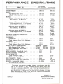 2
2
-
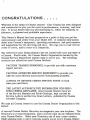 3
3
-
 4
4
-
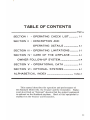 5
5
-
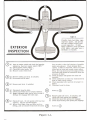 6
6
-
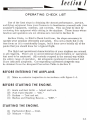 7
7
-
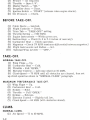 8
8
-
 9
9
-
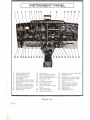 10
10
-
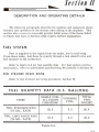 11
11
-
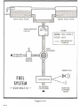 12
12
-
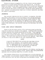 13
13
-
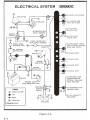 14
14
-
 15
15
-
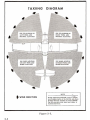 16
16
-
 17
17
-
 18
18
-
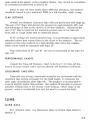 19
19
-
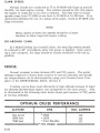 20
20
-
 21
21
-
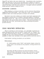 22
22
-
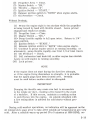 23
23
-
 24
24
-
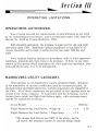 25
25
-
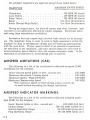 26
26
-
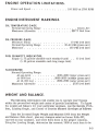 27
27
-
 28
28
-
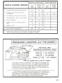 29
29
-
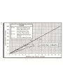 30
30
-
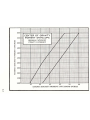 31
31
-
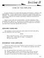 32
32
-
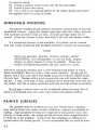 33
33
-
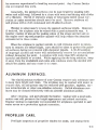 34
34
-
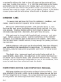 35
35
-
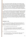 36
36
-
 37
37
-
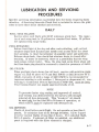 38
38
-
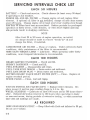 39
39
-
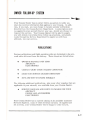 40
40
-
 41
41
-
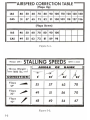 42
42
-
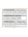 43
43
-
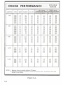 44
44
-
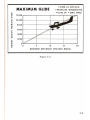 45
45
-
 46
46
-
 47
47
-
 48
48
-
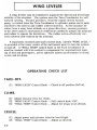 49
49
-
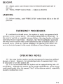 50
50
-
 51
51
-
 52
52
-
 53
53
-
 54
54
-
 55
55
-
 56
56
-
 57
57
-
 58
58


Cessna 150 1969 El manual del propietario
- Categoría
- Juguetes
- Tipo
- El manual del propietario
en otros idiomas
- English: Cessna 150 1969 Owner's manual
Otros documentos
-
Merlin CESSNA T-206 Manual de usuario
-
Kyosho CITABRIA(No.10652) El manual del propietario
-
-
-
-
-
-
-
Black Horse Model BH105 Manual de usuario
-