
IE
CEx BVS 17.0072
de
Betriebsanleitung Motorschutzschalter
für explosionsgefährdete Bereiche .................................. 3
en
Operating instructions for Manual
motor starter
for potentially
explosive areas .......................................... 7
es
Manual de instrucciones Interruptor de protección del
motor para áreas potencialmente explosivas .......................11
fr
Instructions de service disjoncteur-moteur pour
zones explosives ............................................................... 15
it
Istruzioni per salvamotore per zone a rischio
d’esplosione ....................................................................... 19
sv
Bruksanvisning för Motorskyddsbrytare
för explosionsfarliga omgivningar ................................. 23
cn
用于有爆炸危险区域的电机保护开关使用说明书 ..................... 27
ru
Руководство по эксплуатации аппарата защиты
электродвигателя для взрывоопасных зон .................. 31
MS1
32, MS132K
ATEX
—


Mo
torschutzschalter für explosions
g
efährdete
Bereiche MS132, MS132K
Sicherheitshinweise
• Montage und Installation dürfen nur von
ausgebildetem Fachpersonal, nach den
anerkannten technischen Regeln, Vorschriften
und relevanten Normen vorgenommen werden!
• Ungenügend angezogene Klemmschrauben
führen zu unzulässiger Erwärmung!
• Die zulässigen Umgebungsbedingungen sind zu
beachten (siehe technische Daten und Katalog).
• Geräte, die sichtbare Transportschäden
aufweisen, dürfen nicht eingesetzt werden
Allgemeine Beschreibung
Die erhöhte Gefahr bei Einsatz der Geräte in explosionsgefährdeten Bereichen verlangt die konsequente
Beachtung folgender Hinweise und Normen:
• IEC/EN 60079-0 Explosionsfähige Atmosphäre – Teil 0: Allgemeine Anforderungen
• IEC/EN 60079-1 Explosionsfähige Atmosphäre – Teil 1: Geräteschutz durch druckfeste Kapselung „d“
• IEC/EN 60079-7 Explosionsfähige Atmosphäre – Teil 7: Geräteschutz durch erhöhte Sicherheit „e“
• IEC/EN 60079-14 Explosionsfähige Atmosphäre - Teil 14: Projektierung, Auswahl und Errichtung
elektrischer Anlagen
• IEC/EN 60079-17 Explosionsfähige Atmosphäre - Teil 17: Prüfung und Instandhaltung elektrischer Anlagen
• IEC/EN 60079-31 Explosionsfähige Atmosphäre – Teil 31: Geräte-Staubexplosionsschutz durch Gehäuse
• IEC/EN 50495 Sicherheitseinrichtungen für den sicheren Betrieb von Geräten im Hinblick auf
Explosionsgefahren
Der Motorschutzschalter MS132 ist zugelassen unter Gerätegruppe II, Kategorie (2) im Bereich „G“ (Bereiche,
in
denen explosionsfähige Gas-, Dampf-, Nebel-, Luft-Gemische vorhanden sind) und zusätzlich für den
Bereich „D“ (Bereiche mit brennbarem Staub).
BVS 14 ATEX E 009
II (2) G
II (2) D IECEx BVS 17.0072
Der Motorschutzschalter MS132 ist nicht für die Aufstellung bzw. den Betrieb im explosionsgefährdeten Bereich
geeignet.
Bei Verwendung in explosionsgefährdeten Bereichen müssen die Geräte durch entsprechende Maßnahmen der
erforderlichen Zündschutzart entsprechen.
Hinweise
• Bei Ex-Anwendungen ist ein Nachweis der Wirksamkeit der installierten Schutzeinrichtungen vor der
Inbetriebnahme erforderlich!
• Die Schutzfunktion des Gerätes ist der thermische Überlastschutz sowie der Kurzschlussschutz des
Motors.
Im Überlastfall wird der Motor, durch Öffnen der Hauptkontakte des Motorschutzschalters abgeschaltet.
• Der sichere Zustand ist der „Ausgelöst-Zustand“ d.h. Drehgriff in 0-Position oder Trip-Position.
Warnung! Gefährl
iche Spannung!
2CDC131063M680
1e / 08.2018
A
TEX MS132, MS132K - 3
—

Montage und Inbetriebnahme
Der Austausch des MS132 darf nur durch ein gleichwertiges, den Vorschriften entsprechend gekennzeichnetes
Gerät erfolgen.
• Einstellung des Motornennstroms am frontseitigen Einstellknopf.
Hierzu am MS132 die Einstellung auf den Nennstromwert des Motors, gemäß Vorgabe EG-
Baumusterprüfbescheinigung bzw. Typenschild vornehmen.
Bei der Auswahl des Motorschutzschalters ist die Eignung anhand der Auslösekennlinien bzw. Auslöseklasse zu
überprüfen. Maßgebend sind die Werte für das Verhältnis Motoranlauf I
A
zu Motornennstrom I
N
und die kürzeste t
E
-
Zeit, die in der
ATEX-Konformitätsbescheinigung oder in der EG-Baumusterprüfbescheinigung und auf dem Typenschild des Motors
vermerkt
sein müssen. Der Motorschutzschalter muss innerhalb der t
E
-Zeit auslösen, d. h., die Auslösekennlinie aus kaltem
Zustand muss unterhalb des Koordinatenpunktes I
A
/I
N
und der t
E
-Zeit verlaufen.
Die Anschlussleitungen sind entsprechend den Vorgaben, bzw. den anzuwendenden Normen zu dimensionieren.
Sicherheitsdaten MS132
Gemäß DIN EN 50495 können an eine Sicherheitseinrichtung für die Kategorie 2G und 2D die Anforderungen
an einen SIL1 und eine HFT=0 gestellt werden.
Der Motorschutzschalter Baureihe MS132 kann als Komponente einer Sicherheitseinrichtung diese Anforderungen
erfüllen.
2CDC131063M680
1e / 08.2018
4 - ATEX MS1
32, MS132K |

Beispiel:
Der Motor mit erhöhter Sicherheit hat folgende Daten:
4
00 V, 50 Hz/60Hz, 7,5 kW, I
e
= 15 A, I
A
/I
N
= 7,4, Temperaturklasse T3, t
E
-Zeit = 11s Nach unten stehender
Auslösekurve liegt die Auslösezeit unterhalb der t
E
-Zeit des Motors.
elektromagn.
Auslösung ± 20 %
electromagn.
release ± 20 %
elektromagn.
Auslösung
electromagn.
release
tripping time
Auslösezeit
3 polig
three pole two pole
2 polig
Vielfaches vom Nennstrom
multiples of rated
current
3 x Ie
5 x Ie
7.2 x Ie
3 polig
three pole
8.2 s 11.0 s
6.6 s 5.1 s
26.8 s 18.2 s
2 polig
two pole
multiples of rated current I
e
Vielfaches vom Nennstrom I
e
Auslösezeit t
tripping time
x
1
1.2
1.5
2
4
6
7.8
10
11.7
14
16
18
20
5
7.2
I
e
2.5
1.05
0.005
0.01
0.05
0.1
10
s
7
5
4
3
2
50
40
30
20
1
min
3
4
5
2
20
10
1
Std
2
2)
4)
3)
1)
4)
5)
6)
3)
2)
1)
Beispiel
1) 2) 3) 4) 5) 6)
de Vielfaches vom Nennstrom Auslösezeit 2-polig 3-polig elektromagnetische Auslösung elektromagn. Auslösung ± 20 %
es Múltiplos de la intensidad aplicada tiempo de disparo de 2 polos de 3 polos disparo electromagnético disparo electromagnético ± 20 %
fr Multiple du courant de reglage Temps de déclenchement 2 broches 3 broches déclenchement électromagnétique déclenchement électromagn. ± 20 %
it Multiplo della corrente di regolazione Tempo di apertura Bipolare Tripolare rilascio elettromagnetico rilascio elettromagnetico ± 20%
sv Multipelfaktor för utlösningsström Utlösningstid 2-polig 3-polig elektromagnetisk upplösning elektromagn. upplösning ± 20 %
cn 标称电流的多倍 触发时间 双极 三极 电磁触发 电磁触发± 20 %
ru кратностьноминальноготока Времясрабатывания 2-полюсное 3-полюсное электромагнитноерасцепление электромаг.расцепление±20%
2CDC131063M680
1e / 08.2018
A
TEX MS132, MS132K - 5

elektromagn.
Auslösung ± 20 %
electromagn.
release ± 20 %
elektromagn.
Auslösung
electromagn.
release
tripping time
Auslösezeit
3 polig
three pole two pole
2 polig
Vielfaches vom Nennstrom
multiples of rated
current
3 x Ie
5 x Ie
7.2 x Ie
3 polig
three pole
8.2 s 11.0 s
6.6 s 5.1 s
26.8 s 18.2 s
2 polig
two pole
multiples of rated current I
e
Vielfaches vom Nennstrom I
e
Auslösezeit t
tripping time
x
1
1.2
1.5
2
4
6
7.8
10
11.7
14
16
18
20
5
7.2
I
e
2.5
1.05
0.005
0.01
0.05
0.1
10
s
7
5
4
3
2
50
40
30
20
1
min
3
4
5
2
20
10
1
Std
2
Auslösekennlinien aus kaltem Zustand für MS132-2.5
MS132
Auslösekennlinien aus kaltem Zustand
F
ür Nennströme zwischen dem 3- und 8-fachen des Einstellwertes beträgt die Toleranz ± 20 %
D
i
e technische Daten und Kennlinien für weitere Strombereiche finden Sie auf unserer Internetseite
http://new.abb.com/low-voltage/products/motor-protection/manual-motor-starter
2CDC131063M680
1e / 08.2018
6 - ATEX MS1
32, MS132K |

Manual motor starter for potentially explosive areas
MS132, MS132K
Safety instructions
• Mounting and installation may only be done by
trained technical personnel, according to the
recognized technical rules, regulations, and
relevant standards!
• Insufficiently tightened locking screws lead to
an inadmissible rise in temperature!
• Always observe the permitted ambient
conditions (see technical data and catalog).
• Devices with visible transport damage must
not be used.
General description
The extended risks when using these devices in potentially explosive areas requires the consistent adherence to the
following notes and standards:
• IEC/EN 60079-0 Explosive atmospheres – Part 0: General requirements
• IEC/EN 60079-1 Explosive atmospheres – Part 1: Equipment protection by flameproof enclosure "d"
• IEC/EN 60079-7 Explosive atmospheres – Part 7: Equipment protection by increased safety "e"
• IEC/EN 60079-14 Explosive atmospheres - Part 14: Electrical installations design, selection and erection
• IEC/EN 60079-17 Explosive atmospheres - Part 17: Electrical installations inspection and maintenance
• IEC/EN 60079-31 Explosive atmospheres – Part 31: Equipment dust ignition protection by enclosure
• IEC/EN 50495 Safety devices required for the safe functioning of equipment with respect to explosion risks
The MS132 Manual motor starter is authorized under device group II, category (2) in the "G" area (areas with potentially
explosive gas, steam, smoke or air mixtures) and additionally for the "D" area (areas with combustible dust).
BVS 14 ATEX E 009
II (2) G
II (2) D IECEx BVS 17.0072
The MS132 Manual motor starter is not suitable for inst
allation and/or operation in potentially explosive areas. When
using the devices in potentially explosive areas, preventive measures must be taken, e. g. within suitable enclosure.
Notes
• For explosion-proof applications, the efficiency of the installed protection devices has to be verified prior to
commissioning!
• The protection function of the device is the thermal overload protection and protection against short-circuits
in the motor. In case of an overload trip, the motor is switched off by opening the main contacts of the Manual
motor starter.
• The safe state is the "tripped state", i.e., turning handle in 0-position or trip position.
W
arning! Hazardous
voltage!
2CDC131063M680
1e / 08.2018
A
TEX MS132, MS132K - 7
—

Mounting and commissioning
The MS132 may only be replaced by an equivalent device, marked in accordance with the
regulations.
• Setting the rated motor current is done using the adjusting knob on the front side.
For this purpose, the rated motor current has to be adjusted at the MS132 according to the EC type
examination certificate specification and/or the type plate.
When selecting the Manual motor starter, check its suitability by means of the trip curves and/or the trip class.
Decisive values are the ratio between the motor startup current I
A
and the rated motor current I
N
, as well as the
shortest time t
E
. These values have to be marked in the ATEX certificate of conformity or in the EC type
examination certificate and on the type plate of the
motor. The Manual motor starter must trip within the time t
E
. This means that the trip curve from the cold state
has to be below the coordination point I
A
/I
N
and the time t
E
.
The connecting cables have to be dimensioned according to the specifications and/or the applicable standards.
Safety specifications MS132
According to DIN EN 50495, the requirements for a SIL 1 and a HFT = 0 can be placed on safety equipment for
categories 2G and 2D.
The MS132 Manual motor starter can meet these requirements if used as a component of the safety equipment.
2CDC131063M680
1e / 08.2018
8 - ATEX MS1
32, MS132K |

Example:
The motor with enhanced safety has the following data:
400 V, 50 Hz/60Hz, 7.5 kW, I
e
= 15 A, I
A
/I
N
= 7.4, temperature class T3, time t
E
= 11s
According to the tripping curve below , the trip time is smaller than the time t
E
of
the motor.
elektromagn.
Auslösung ± 20 %
electromagn.
release ± 20 %
elektromagn.
Auslösung
electromagn.
release
tripping time
Auslösezeit
3 polig
three pole two pole
2 polig
Vielfaches vom Nennstrom
multiples of rated
current
3 x Ie
5 x Ie
7.2 x Ie
3 polig
three pole
8.2 s 11.0 s
6.6 s 5.1 s
26.8 s 18.2 s
2 polig
two pole
multiples of rated current I
e
Vielfaches vom Nennstrom I
e
Auslösezeit t
tripping time
x
1
1.2
1.5
2
4
6
7.8
10
11.7
14
16
18
20
5
7.2
I
e
2.5
1.05
0.005
0.01
0.05
0.1
10
s
7
5
4
3
2
50
40
30
20
1
min
3
4
5
2
20
10
1
Std
2
2)
4)
3)
1)
4)
5)
6)
3)
2)
1)
Example
1) 2) 3) 4) 5) 6)
de Vielfaches vom Nennstrom Auslösezeit 2-polig 3-polig elektromagnetische Auslösung elektromagn. Auslösung ± 20 %
es Múltiplos de la intensidad aplicada tiempo de disparo de 2 polos de 3 polos disparo electromagnético disparo electromagnético ± 20 %
fr Multiple du courant de reglage Temps de déclenchement 2 broches 3 broches déclenchement électromagnétique déclenchement électromagn. ± 20 %
it Multiplo della corrente di regolazione Tempo di apertura Bipolare Tripolare rilascio elettromagnetico rilascio elettromagnetico ± 20%
sv Multipelfaktor för utlösningsström Utlösningstid 2-polig 3-polig elektromagnetisk upplösning elektromagn. upplösning ± 20 %
cn 标称电流的多倍 触发时间 双极 三极 电磁触发 电磁触发± 20 %
ru кратностьноминальноготока Времясрабатывания 2-полюсное 3-полюсное электромагнитноерасцепление электромаг.расцепление±20%
2CDC131063M680
1e / 08.2018
A
TEX MS132, MS132K - 9

elektromagn.
Auslösung ± 20 %
electromagn.
release ± 20 %
elektromagn.
Auslösung
electromagn.
release
tripping time
Auslösezeit
3 polig
three pole two pole
2 polig
Vielfaches vom Nennstrom
multiples of rated
current
3 x Ie
5 x Ie
7.2 x Ie
3 polig
three pole
8.2 s 11.0 s
6.6 s 5.1 s
26.8 s 18.2 s
2 polig
two pole
multiples of rated current I
e
Vielfaches vom Nennstrom I
e
Auslösezeit t
tripping time
x
1
1.2
1.5
2
4
6
7.8
10
11.7
14
16
18
20
5
7.2
I
e
2.5
1.05
0.005
0.01
0.05
0.1
10
s
7
5
4
3
2
50
40
30
20
1
min
3
4
5
2
20
10
1
Std
2
Tripping curves for MS132-2.5 from a cold state
MS132
Tripping curves from a cold state
For nominal currents between
three and eight times the setpoint, the tolerance is ± 20 %
The technical specifications and characteristic curves for other current ranges
can be found on our Web site
http://new.abb.com/low-voltage/produ
cts/motor-protection/manual-motor-starter
2CDC131063M680
1e / 08.2018
10 - ATEX MS
132, MS132K |

Interruptor de protección de motor para áreas
potencialmente explosivas
MS132, MS132K
Instrucciones de seguridad
• ¡El montaje y la instalación únicamente
deberán ser efectuados por personal
especializado con la respectiva formación
profesional,
en conformidad con las reglas técnicas
reconocidas, las especificaciones y normas
relevantes!
• ¡Tornillos de conexión no apretados
suficientemente causarán un calentamiento
inadmisible!
• Se deberán observar las condiciones
ambientales admisibles (véanse los datos
técnicos y el catálogo).
• No se deberán emplear aquellos dispositivos
que muestren daños de transporte visibles
Descripción general
Los riesgos al emplear los dispositivos en áreas potencialmente explosivas exigen la observación consecuente de las
siguientes instrucciones y normas:
• IEC/EN 60079-0 Atmósferas explosivas – Parte 0: Requerimientos generales
• IEC/EN 60079-1 Atmósferas explosivas – Parte 1: Protección de equipos mediante envolvente antideflagrante
"d"
• IEC/EN 60079-7 Atmósferas explosivas – Parte 7: Protección de equipos mediante mayor seguridad "e"
• IEC/EN 60079-14 Atmósferas explosivas – Parte 14: Diseño, elección y realización de instalaciones eléctricas
• IEC/EN 60079-17 Atmósferas explosivas – Parte 17: Inspección y mantenimiento de instalaciones eléctricas
• IEC/EN 60079-31 Atmósferas explosivas – Parte 31:
Protección contra explosión de polvo de equipos
mediante carcasa
• IEC/EN 50495 Dispositivos de seguridad requeridos para el funcionamiento seguro de un equipo respecto a
los riesgos de explosión
El interruptor de protección del motor MS132 forma parte del grupo de dispositivos II, categoría (2) y está
h
omologado para el uso en entornos de la categoría "G" (existencia de mezclas explosivas de gas, vapor, humo o
mezclas de aire) y adicionalmente para el entorno "D" (existencia de polvo inflamable).
BVS 14 ATEX E 009
II (2) G
II (2) D IECEx BVS 17.0072
El interruptor de protección de motor MS132 no es apropiado para la instalación o bien el funcionamiento en
áreas potencialmente explosivas.
En caso de su utilización en áreas potencialmente explosivas, los dispositivos deberán corresponder al tipo de
protección requerido adoptando las medidas correspondientes.
Notas
• ¡En el caso de aplicaciones Ex, se requerirá la demostración de la eficacia de los dispositivos de protección
instalados antes de la puesta en funcionamiento!
• La función de protección del dispositivo es la protección de sobrecarga térmica, así como la protección de
cortocircuito del motor.
En caso de sobrecarga, el motor será apagado mediante la apertura de los contactos principales del
interruptor de protección de motor.
• El estado seguro es el "estado de disparado", es decir el botón giratorio está en la posición 0 o en la posición
de disparo.
¡Advertencia! ¡Tensión peligrosa!
2CDC131063M680
1e / 08.2018
ATEX MS132, MS132K - 11
—

Montaje y puesta en funcionamiento
La sustitución del MS132 únicamente deberá ser realizada con algún dispositivo equivalente, el cual
corresponda a las especificaciones.
• Ajuste de la corriente nominal del motor a través del regulador de ajuste en el lado frontal.
Para esto, efectuar el ajuste del valor de corriente nominal del motor en el MS132 según la especificación del
certificado de examen CE de tipo o bien de la placa de características.
Al seleccionar el interruptor de protección de motor, se deberá comprobar su idoneidad en base de las curvas
características de disparo o bien la clase de disparo. Prevalecerán los valores de la relación de corriente de arranque
del motor I
A
y corriente nominal del motor I
N
y el tiempo t
E
más corto, los cuales deberán estar anotados en el
certificado de conformidad ATEX o en el certificado de examen CE de tipo y en la placa de características del motor.
El interruptor de protección de motor deberá
disparar dentro del tiempo t
E
, es decir que la curva característica de disparo desde el estado frío deberá desarrollarse
por debajo del punto de coordenadas I
A
/I
N
y el tiempo t
E
.
Los cables de conexión deberán ser dimensionados en conformidad con las especificaciones o bien las normas
aplicables.
Datos de seguridad del MS132
Según DIN EN 50495, los requerimientos para un SIL1 y HFT=0 deben ser satisfechos en dispositivos de seguridad
categoría 2G y 2D.
El interruptor de protección del motor de la serie MS132 puede satisfacer estas exigencias como componente de un
dispositivo de seguridad.
2CDC131063M680
1e / 08.2018
12 - ATEX M
S132, MS132K |

Ejemplo:
El motor con seguridad aumentada presenta los siguientes datos:
400 V, 50 Hz/60Hz, 7,5 kW, I
e
= 15 A, I
A
/I
N
= 7,4, clase de temperatura T3, tiempo t
E
= 11s
Según la curva de disparo indicada más abajo, el tiempo de disparo se encuentra por debajo del tiempo t
E
del motor.
elektromagn.
Auslösung ± 20 %
electromagn.
release ± 20 %
elektromagn.
Auslösung
electromagn.
release
tripping time
Auslösezeit
3 polig
three pole two pole
2 polig
Vielfaches vom Nennstrom
multiples of rated
current
3 x Ie
5 x Ie
7.2 x Ie
3 polig
three pole
8.2 s 11.0 s
6.6 s 5.1 s
26.8 s 18.2 s
2 polig
two pole
multiples of rated current I
e
Vielfaches vom Nennstrom I
e
Auslösezeit t
tripping time
x
1
1.2
1.5
2
4
6
7.8
10
11.7
14
16
18
20
5
7.2
I
e
2.5
1.05
0.005
0.01
0.05
0.1
10
s
7
5
4
3
2
50
40
30
20
1
min
3
4
5
2
20
10
1
Std
2
2)
4)
3)
1)
4)
5)
6)
3)
2)
1)
Ejemplo
1) 2) 3) 4) 5) 6)
de Vielfaches vom Nennstrom Auslösezeit 2-polig 3-polig elektromagnetische Auslösung elektromagn. Auslösung ± 20 %
es Múltiplos de la intensidad aplicada tiempo de disparo de 2 polos de 3 polos disparo electromagnético disparo electromagnético ± 20 %
fr Multiple du courant de reglage Temps de déclenchement 2 broches 3 broches déclenchement électromagnétique déclenchement électromagn. ± 20 %
it Multiplo della corrente di regolazione Tempo di apertura Bipolare Tripolare rilascio elettromagnetico rilascio elettromagnetico ± 20%
sv Multipelfaktor för utlösningsström Utlösningstid 2-polig 3-polig elektromagnetisk upplösning elektromagn. upplösning ± 20 %
cn 标称电流的多倍 触发时间 双极 三极 电磁触发 电磁触发± 20 %
ru кратностьноминальноготока Времясрабатывания 2-полюсное 3-полюсное электромагнитноерасцепление электромаг.расцепление±20%
2CDC131063M680
1e / 08.2018
ATEX MS132, MS132K - 13

elektromagn.
Auslösung ± 20 %
electromagn.
release ± 20 %
elektromagn.
Auslösung
electromagn.
release
tripping time
Auslösezeit
3 polig
three pole two pole
2 polig
Vielfaches vom Nennstrom
multiples of rated
current
3 x Ie
5 x Ie
7.2 x Ie
3 polig
three pole
8.2 s 11.0 s
6.6 s 5.1 s
26.8 s 18.2 s
2 polig
two pole
multiples of rated current I
e
Vielfaches vom Nennstrom I
e
Auslösezeit t
tripping time
x
1
1.2
1.5
2
4
6
7.8
10
11.7
14
16
18
20
5
7.2
I
e
2.5
1.05
0.005
0.01
0.05
0.1
10
s
7
5
4
3
2
50
40
30
20
1
min
3
4
5
2
20
10
1
Std
2
Curvas características de disparo desde el estado frío para MS132-2.5
MS132
Curvas características de disparo desde el estado frío
Para corrientes nominales entre 3 y 8 veces el valor de ajuste, la tolerancia será de ± 20 %
Los datos técnicos y las curvas características para otro
s rangos de corriente se encuentran en nuestra página web
http://new.abb.com/low-voltage/products/motor-protection/manual-motor-starter
2CDC131063M680
1e / 08.2018
14 - ATEX MS
132, MS132K |

Disjoncteur-moteur pour zones explosives
MS132, MS132K
Consignes de sécurité
• Le montage et l’installation doivent être
exécutés exclusivement par du personnel
qualifié et dûment formé, selon les
réglementations techniques applicables et en
respectant les normes en vigueur !
• Des vis de serrage insuffisamment serrées
peuvent provoquer un échauffement
excessif !
• Respecter les conditions ambiantes
admissibles (cf. Caractéristiques techniques
et catalogue).
• Ne pas utiliser les appareils qui présentent
des dommages visibles dus au transport.
Description générale
Le risque accru lors de l‘utilisation des appareils en zones explosives demande le respect strict des consignes
et normes suivantes :
• IEC/EN 60079-0 Atmosphères explosives – Partie 0 : Exigences générales
• IEC/EN 60079-1 Atmosphères explosives – Partie 1 : Protection du matériel par enveloppes antidéflagrantes «
d »
• IEC/EN 60079-7 Atmosphères explosives – Partie 7 : Protection de l’équipement par sécurité augmentée « e »
• IEC/EN 60079-14 Atmosphères explosives – Partie 14 : Conception, sélection et construction des installations
électriques
• IEC/EN 60079-17 Atmosphères explosives – Partie 17 : Inspection et maintenance des installations électriques
• IEC/EN 60079-31 Atmosphères explosives – Partie 31 : Protection du matériel contre l’inflammation des
poussières par enveloppe
• IEC/EN 50495 Dispositifs de sécurité nécessaires pour le fonctionnement sûr d’un matériel vis-à-vis des
risques d’explosion
Le disjoncteur-moteur MS 132 est certifié pour le groupe
d‘appareils II, catégorie (2) dans la zone « G » (zones où se
trouvent des mélanges explosifs de gaz, de vapeur, de brouillard et d‘air) ainsi que pour la zone « D » (zones avec
poussières combustibles).
BVS 14 ATEX E 009
II (2) G
II (2) D IECEx BVS 17.0072
Le disjoncteur-moteur MS132 n‘est pas approprié pour une implantation ou bien un fonctionnement dans des zones
explosives.
En cas d‘utilisation dans des zones explosives, les appareils doivent être conformes au mode de protection requis en
prenant les mesures appropriées.
Notes
• Pour des applications Ex, il est indispensable de certifier l’efficacité des dispositifs de protection installés
avant la mise en service !
• La fonction de l’appareil est de protéger le moteur contre les surcharges thermiques et les courts-circuits.
En cas de surcharge, l’alimentation du moteur sera coupée en ouvrant les contacts principaux du disjoncteur-
moteur.
• La sécurité est assurée par un « état déclenché », c.-à-d. poignée rotative en position 0 ou Trip.
A
vertissement! Tension électrique dangereuse!
2CDC131063M680
1e / 08.2018
ATEX MS132, MS132K - 15
—

Montage et mise en service
Le remplacement du disjoncteur-moteur MS 132 s‘effectue toujours par un appareil de même type marqué
conformément aux prescriptions en vigueur.
• Le réglage du courant nominal moteur s’effectue par rotation du potentiomètre sur la face avant.
Le courant nominal du moteur doit être réglé conformément aux spécifications CE et/ou aux données
de la plaque signalétique du moteur.
Lors de la sélection du disjoncteur-moteur, s‘assurer de son adéquation au besoin à l‘aide des caractéristiques
techniques et de la classe de déclenchement. Les valeurs à prendre en compte sont le rapport entre le courant de
démarrage moteur I
A
et le courant nominal I
N
, et le temps de déclenchement t
E
. Ces valeurs doivent figurer dans le
certificat ATEX, ou dans l‘attestation d‘examen CE ou sur la plaque signalétique du moteur. Le disjoncteur-moteur
doit déclencher dans un temps inférieur au temps t
E
, en d‘autre termes, la courbe de déclenchement à l‘état froid
doit passer en dessous des coordonnées du point I
A
/I
N
; t
E
(voir exemple).
Le dimensionnement des câbles de raccordement doit s‘effectuer conformément aux spécifications ou bien aux
normes en vigueur.
Données de sécurité disjoncteur-moteur MS132
Selon la norme DIN EN 50495, un dispositif de sécurité prévu pour la catégorie 2G et 2D doit remplir les exigences
suivantes : SIL1 et HFT = 0.
Le disjoncteur-moteur de la série MS132 peut satisfaire à ces exigences comme composant d‘un dispositif de
sécurité.
2CDC131063M680
1e / 08.2018
16 - ATEX MS
132, MS132K |

Exemple :
Pour un moteur à sécuri
té renforcée présentant les caractéristiques suivantes :
400 V, 50 Hz/60 Hz, 7,5 kW, I
e
= 15 A, I
A
/I
N
= 7,4, classe de température T3, temps t
E
= 11 s
Selon la courbe de déclenchement ci-dessous, le temps de déclenchement est au-dessous du temps t
E
du moteur.
elektromagn.
Auslösung ± 20 %
electromagn.
release ± 20 %
elektromagn.
Auslösung
electromagn.
release
tripping time
Auslösezeit
3 polig
three pole two pole
2 polig
Vielfaches vom Nennstrom
multiples of rated
current
3 x Ie
5 x Ie
7.2 x Ie
3 polig
three pole
8.2 s 11.0 s
6.6 s 5.1 s
26.8 s 18.2 s
2 polig
two pole
multiples of rated current I
e
Vielfaches vom Nennstrom I
e
Auslösezeit t
tripping time
x
1
1.2
1.5
2
4
6
7.8
10
11.7
14
16
18
20
5
7.2
I
e
2.5
1.05
0.005
0.01
0.05
0.1
10
s
7
5
4
3
2
50
40
30
20
1
min
3
4
5
2
20
10
1
Std
2
2)
4)
3)
1)
4)
5)
6)
3)
2)
1)
Exemple
1) 2) 3) 4) 5) 6)
de Vielfaches vom Nennstrom Auslösezeit 2-polig 3-polig elektromagnetische Auslösung elektromagn. Auslösung ± 20 %
es Múltiplos de la intensidad aplicada tiempo de disparo de 2 polos de 3 polos disparo electromagnético disparo electromagnético ± 20 %
fr Multiple du courant de reglage Temps de déclenchement 2 broches 3 broches déclenchement électromagnétique déclenchement électromagn. ± 20 %
it Multiplo della corrente di regolazione Tempo di apertura Bipolare Tripolare rilascio elettromagnetico rilascio elettromagnetico ± 20%
sv Multipelfaktor för utlösningsström Utlösningstid 2-polig 3-polig elektromagnetisk upplösning elektromagn. upplösning ± 20 %
cn 标称电流的多倍 触发时间 双极 三极 电磁触发 电磁触发± 20 %
ru кратностьноминальноготока Времясрабатывания 2-полюсное 3-полюсное электромагнитноерасцепление электромаг.расцепление±20%
2CDC131063M680
1e / 08.2018
ATEX MS132, MS132K - 17

elektromagn.
Auslösung ± 20 %
electromagn.
release ± 20 %
elektromagn.
Auslösung
electromagn.
release
tripping time
Auslösezeit
3 polig
three pole two pole
2 polig
Vielfaches vom Nennstrom
multiples of rated
current
3 x Ie
5 x Ie
7.2 x Ie
3 polig
three pole
8.2 s 11.0 s
6.6 s 5.1 s
26.8 s 18.2 s
2 polig
two pole
multiples of rated current I
e
Vielfaches vom Nennstrom I
e
Auslösezeit t
tripping time
x
1
1.2
1.5
2
4
6
7.8
10
11.7
14
16
18
20
5
7.2
I
e
2.5
1.05
0.005
0.01
0.05
0.1
10
s
7
5
4
3
2
50
40
30
20
1
min
3
4
5
2
20
10
1
Std
2
Courbes de déclenchement à l‘état froid pour MS132-2.5
MS132
C
ourbes de déclenchement à l‘état froid
La tolérance est de ± 20 % pour des courants nominaux entre 3 et 8 fois la valeur de consigne
Vo
us trouverez les caractéristiques techniques et courbes pour d‘autres plages d‘intensité sur notre site Internet
http://new.abb.com/low-voltage/produ
cts/motor-protection/manual-motor-starter
2CDC131063M680
1e / 08.2018
18 - ATEX M
S132, MS132K |

Salvamotore per zone a rischio d’esplosione
MS132, MS132K
Istruzioni di sicurezza
• Le operazioni di montaggio e installazione
sono riservate a personale specializzato
esperto delle regole della tecnica
comunemente accettate, disposizioni e della
relativa normativa!
• Il serraggio non corretto dei morsetti può
provocare un surriscaldamento eccessivo!
• Rispettare le condizioni ambientali ammesse
(si vedano i dati tecnici e il catalogo).
• Non è ammessa l'installazione del dispositivo
nel caso siano presenti evidenti danni da
trasporto
Descrizione generale
Il maggior rischio dovuto all’utilizzo dei dispositivi in zone a rischio d’esplosione richiede il rigoroso rispetto
delle seguenti indicazioni e norme:
• IEC/EN 60079-0 Atmosfere esplosive – Parte 0: Requisiti generali
• IEC/EN 60079-1 Atmosfere esplosive – Parte 1: Protezione mediante custodia a prova d’esplosione "d"
• IEC/EN 60079-7 Atmosfere esplosive – Parte 7: Apparecchiature con modo di protezione a sicurezza
aumentata "e"
• IEC/EN 60079-14 Atmosfere esplosive – Parte 14: Progettazione, scelta e installazione degli impianti
elettrici
• IEC/EN 60079-17 Atmosfere esplosive – Parte 17: Verifica e manutenzione degli impianti elettrici
• IEC/EN 60079-31 Atmosfere esplosive – Parte 31: Protezione contro polveri combustibili mediante
custodia
• IEC/EN 50495 sistemi di sicurezza negli impianti con rischio di esplosione
Il salvamotore MS132 è omologato per il gruppo dispositivi II, categoria (2) nell’area "G" (area nella quale sono
presenti miscele di
gas, vapore, nebbia e aria deflagranti) e inoltre per l’area zona "D" (area con polveri esplosive).
BVS 14 ATEX E 009
II (2) G
II (2) D IECEx BVS 17.0072
Il salvamotore MS132 non è idoneo all’utilizzo e al funzionamento in zone a rischio d’esplosione.
In caso di installazione in zone a rischio d’esplosione, i dispositivi devono essere dotati del tipo di protezione
antideflagrante con misure addizionali.
Indicazioni
• Per applicazioni Ex, prima della messa in funzione è necessaria la dimostrazione dell’efficacia delle
protezioni installate!
• Il salvamotore svolge la funzione di protezione contro il sovraccarico termico e contro corto circuito di
motori.
In caso di sovraccarico, il motore viene disinserito mediante l’apertura dei contatti principali del
salvamotore.
• Lo stato sicuro è lo "stato di scatto", cioè con manopola in posizione "0" o Trip.
Avv
ertenza! Tensione pericolosa!
2CDC131063M680
1e / 08.2018
ATEX MS132, MS132K - 19
—

Installazione e messa in servizio
La sostituzione del relè MS132 è permessa solo con un dispositivo equivalente, contrassegnato come richiesto dalla
normativa.
• Regolazione della corrente nominale del motore mediante il trimmer di regolazione frontale.
Sull’ MS132 impostare il valore della corrente nominale del motore in base all’omologazione di tipo CE risp. alla
targhetta conoscitiva.
Per selezionare un salvamotore adatto, verificarne l’idoneità in base alle caratteristiche d’intervento rispondenti alla
classe d’intervento. Sono fondamentali i valori per il rapporto tra la corrente di avviamento I
A
e la corrente motore
nominale I
N
e il l’intervallo minimo t
E
che devono essere riportati nella dichiarazione di conformità ATEX o
nell’omologazione di tipo CE nonché sulla targhetta conoscitiva del motore. Il salvamotore deve intervenire entro il
tempo t
E
, la caratteristica d’intervento allo stato a freddo cioè deve essere inferiore alla coordinata I
A
/I
N
e al tempo t
E
.
Dimensionare i cavi di connessione in base alle indicazione risp. alla normativa applicabile.
Dati di sicurezza MS132
In base alla norma DIN EN 50495, a un dispositivo di sicurezza per la categoria 2G e 2D si possono porre i requisiti
per un SIL1 e una HFT=0.
Il salvamotore della serie MS132, utilizzato come componente di un dispositivo di sicurezza, è in grado di soddisfare
questi requisiti.
2CDC131063M680
1e / 08.2018
20 - ATEX M
S132, MS132K |

Esempio:
Il motore in condizioni di
sicurezza maggiori ha le seguenti caratteristiche:
400 V, 50 Hz/60Hz, 7,5 kW, I
e
= 15 A, I
A
/I
N
= 7,4, classe di temperatura T3, tempo t
E
= 11s
In base alla caratteristica d’intervento sottostante, l’intervallo d’intervento è inferiore al tempo t
E
del motore.
elektromagn.
Auslösung ± 20 %
electromagn.
release ± 20 %
elektromagn.
Auslösung
electromagn.
release
tripping time
Auslösezeit
3 polig
three pole two pole
2 polig
Vielfaches vom Nennstrom
multiples of rated
current
3 x Ie
5 x Ie
7.2 x Ie
3 polig
three pole
8.2 s 11.0 s
6.6 s 5.1 s
26.8 s 18.2 s
2 polig
two pole
multiples of rated current I
e
Vielfaches vom Nennstrom I
e
Auslösezeit t
tripping time
x
1
1.2
1.5
2
4
6
7.8
10
11.7
14
16
18
20
5
7.2
I
e
2.5
1.05
0.005
0.01
0.05
0.1
10
s
7
5
4
3
2
50
40
30
20
1
min
3
4
5
2
20
10
1
Std
2
2)
4)
3)
1)
4)
5)
6)
3)
2)
1)
Esempio
1) 2) 3) 4) 5) 6)
de Vielfaches vom Nennstrom Auslösezeit 2-polig 3-polig elektromagnetische Auslösung elektromagn. Auslösung ± 20 %
es Múltiplos de la intensidad aplicada tiempo de disparo de 2 polos de 3 polos disparo electromagnético disparo electromagnético ± 20 %
fr Multiple du courant de reglage Temps de déclenchement 2 broches 3 broches déclenchement électromagnétique déclenchement électromagn. ± 20 %
it Multiplo della corrente nominale Tempo di apertura Bipolare Tripolare Sgancio elettromagnetico Sgancio elettromagnetico ± 20%
sv Multipelfaktor för utlösningsström Utlösningstid 2-polig 3-polig elektromagnetisk upplösning elektromagn. upplösning ± 20 %
cn 标称电流的多倍 触发时间 双极 三极 电磁触发 电磁触发± 20 %
ru кратностьноминальноготока Времясрабатывания 2-полюсное 3-полюсное электромагнитноерасцепление электромаг.расцепление±20%
2CDC131063M680
1e / 08.2018
ATEX MS132, MS132K - 21

elektromagn.
Auslösung ± 20 %
electromagn.
release ± 20 %
elektromagn.
Auslösung
electromagn.
release
tripping time
Auslösezeit
3 polig
three pole two pole
2 polig
Vielfaches vom Nennstrom
multiples of rated
current
3 x Ie
5 x Ie
7.2 x Ie
3 polig
three pole
8.2 s 11.0 s
6.6 s 5.1 s
26.8 s 18.2 s
2 polig
two pole
multiples of rated current I
e
Vielfaches vom Nennstrom I
e
Auslösezeit t
tripping time
x
1
1.2
1.5
2
4
6
7.8
10
11.7
14
16
18
20
5
7.2
I
e
2.5
1.05
0.005
0.01
0.05
0.1
10
s
7
5
4
3
2
50
40
30
20
1
min
3
4
5
2
20
10
1
Std
2
Caratteristiche d’intervento da
stato a freddo per MS132-2.5
MS132
Caratteristiche d’intervento da stato a freddo
Per correnti nominali da 3 a 8 volte il valore di regolazione la tolleranza è del ± 20 %
Per i dati tecnici e le caratteristiche relative ad altr
i modelli con altre regolazioni si veda la nostra pagina internet:
http://new.abb.com/low-voltage/produ
cts/motor-protection/manual-motor-starter
2CDC131063M680
1e / 08.2018
22 - ATEX MS
132, MS132K |

Motorskyddsbrytare för explosionsfarliga omgivningar
MS132, MS132K
Säkerhetsföreskrifter
• Montering och installation får endast utföras
av utbildad personal, i enlighet med erkända
tekniska regler, föreskrifter och gällande
normer!
• Otillräckligt åtdragna anslutningsskruvar
orsakar otillåten uppvärmning!
• Tillåtna omgivningsförhållanden ska beaktas
(se tekniska data och katalog).
• Enhet som uppvisar synliga transportskador
får inte användas.
Allmän beskrivning
Den ökade risken vid användning av utrustning i explosionsfarliga miljöer kräver att följande anvisningar och
normer följs konsekvent:
• IEC/EN 60079-0 Explosiv atmosfär - Del 0: Allmänna fordringar
• IEC/EN 60079-1 Explosiv atmosfär - Del 1: Utförande med explosionstät kapsling ”d”
• IEC/EN 60079-7 Explosiv atmosfär - Del 7: Utförande med höjd säkerhet ”e”
• IEC/EN 60079-14 Explosiv atmosfär - Del 14: Konstruktion, val och utförande av elinstallationer
• IEC/EN 60079-17 Explosiv atmosfär - Del 17: Kontroll och underhåll av elektriska installationer
• IEC/EN 60079-31 Explosiv atmosfär - Del 31: Utrustning i utförande med dammskyddande kapsling
• IEC/EN 50495 Säkerhetsanordningar som fordras för att utrustningen ska fungera säkert, med
avseende på explosionsrisk
Motorskyddsbrytaren MS132 är godkänd i enlighet med apparatgrupp II, kategor
i (2) i område ”G” (områden
där det finns explosionsfarliga gas-, ång-, dim- och luftblandningar) och dessutom för område ”D” (områden
med lättantändligt damm).
BVS 14 ATEX E 009
II (2) G
II (2) D IECEx BVS 17.0072
Motorskyddsbrytaren MS132 är inte lämplig för uppställning eller drift i explosionsfarliga miljöer.
Vid användning i explosionsfarliga miljöer måste enheten uppfylla kraven för nödvändig antändningstyp.
H
änvisning
• Vid Ex-användningar krävs ett intyg på effektiviteten hos den installerade skyddsanordningen före
idrifttagning!
• Enhetens skyddsfunktion är termiskt överbelastningsskydd samt kortslutningsskydd av motorn.
Vid överbelastning kopplas motorn från genom att huvudkontakten till motorskyddsbrytaren
öppnas.
• Säkert tillstånd är ”Utlösningstillstånd” dvs vredet i 0-position eller trip-position.
V
arning! Farlig spänning!
2CDC131063M680
1e / 08.2018
ATEX MS132, MS132K - 23
—

Montering och idrifttagn
i
ng
MS132 får endast bytas mot en likvärdig enhet som uppfyller föreskrifterna.
• Ställ in motorns märkström med inställningsknappen på framsidan.
Ställ in märkströmmen för motorn på MS132 i enlighet med uppgifterna i EU-intyget eller på
typskylten.
Vid val av motorskyddsbr
ytaren ska lämpligheten kontrolleras med hjälp av utlösningskarakteristiken samt
utlösningsklassen. Värdena för förhållandet mellan motorstartströmmen I
A
och motormärkströmmen I
N
och
kortaste t
E
-tid, som måste vara angivna på ATEX-intyget, i EU-godkännandet och på motorns typskylt.
Motorskyddsbrytaren måste lösa ut inom t
E
-tiden, dvs. utlösningskarakteristiken från kallt tillstånd måste ligga
under koordinatpunkterna I
A
/I
N
och t
E
-tiden.
Anslutningsledningarna ska dimensioneras i enlighet med anläggningsdata, samt tillämpade standarder.
Säkerhetsdata för MS132
Enligt DIN EN 50495 kan kraven på en SIL1 och en HFT=0 ställas på en säkerhetsanordning för kategori 2G och 2D.
Motorskyddsbrytaren i serien MS132 kan uppfylla dessa krav som en komponent i en säkerhetsanordning.
2CDC131063M680
1e / 08.2018
24 - ATEX M
S132, MS132K |

Ex
empel:
M
otorn med ökad säkerhet har följande data:
400 V, 50/60Hz, 7,5 kW, I
e
= 15 A, I
A
/I
N
= 7,4, temperaturklass T3, t
E
-tid = 11s Enligt nedanstående utlösningskurva
ligger utlösningstiden under t
E
-tiden för motorn.
elektromagn.
Auslösung ± 20 %
electromagn.
release ± 20 %
elektromagn.
Auslösung
electromagn.
release
tripping time
Auslösezeit
3 polig
three pole two pole
2 polig
Vielfaches vom Nennstrom
multiples of rated
current
3 x Ie
5 x Ie
7.2 x Ie
3 polig
three pole
8.2 s 11.0 s
6.6 s 5.1 s
26.8 s 18.2 s
2 polig
two pole
multiples of rated current I
e
Vielfaches vom Nennstrom I
e
Auslösezeit t
tripping time
x
1
1.2
1.5
2
4
6
7.8
10
11.7
14
16
18
20
5
7.2
I
e
2.5
1.05
0.005
0.01
0.05
0.1
10
s
7
5
4
3
2
50
40
30
20
1
min
3
4
5
2
20
10
1
Std
2
2)
4)
3)
1)
4)
5)
6)
3)
2)
1)
Exempel
1) 2) 3) 4) 5) 6)
de Vielfaches vom Nennstrom Auslösezeit 2-polig 3-polig elektromagnetische Auslösung elektromagn. Auslösung ± 20 %
es Múltiplos de la intensidad aplicada tiempo de disparo de 2 polos de 3 polos disparo electromagnético disparo electromagnético ± 20 %
fr Multiple du courant de reglage Temps de déclenchement 2 broches 3 broches déclenchement électromagnétique déclenchement électromagn. ± 20 %
it Multiplo della corrente di regolazione Tempo di apertura Bipolare Tripolare rilascio elettromagnetico rilascio elettromagnetico ± 20%
sv Multipelfaktor för utlösningsström Utlösningstid 2-polig 3-polig elektromagnetisk utlösningsström elektromagn. utlösningsström ± 20 %
cn 标称电流的多倍 触发时间 双极 三极 电磁触发 电磁触发± 20 %
ru кратностьноминальноготока Времясрабатывания 2-полюсное 3-полюсное электромагнитноерасцепление электромаг.расцепление±20%
2CDC131063M680
1e / 08.2018
ATEX MS132, MS132K - 25

elektromagn.
Auslösung ± 20 %
electromagn.
release ± 20 %
elektromagn.
Auslösung
electromagn.
release
tripping time
Auslösezeit
3 polig
three pole two pole
2 polig
Vielfaches vom Nennstrom
multiples of rated
current
3 x Ie
5 x Ie
7.2 x Ie
3 polig
three pole
8.2 s 11.0 s
6.6 s 5.1 s
26.8 s 18.2 s
2 polig
two pole
multiples of rated current I
e
Vielfaches vom Nennstrom I
e
Auslösezeit t
tripping time
x
1
1.2
1.5
2
4
6
7.8
10
11.7
14
16
18
20
5
7.2
I
e
2.5
1.05
0.005
0.01
0.05
0.1
10
s
7
5
4
3
2
50
40
30
20
1
min
3
4
5
2
20
10
1
Std
2
Utlösningskarakteristik i kallt tillstånd för MS132-2.5
MS132
Utlösningskarakteristik i kallt tillstånd
F
ör märkströmmar mellan tre och åtta gånger inställningsvärdet är toleransen ± 20 %
Tekniska data och karakteristik för övriga strömintervall finns på vår hemsida
http://new.abb.com/low-voltage/produ
cts/motor-protection/manual-motor-starter
2CDC131063M680
1e / 08.2018
26 - ATEX MS
132, MS132K |

用于有爆炸危险区域的电动机起动器
MS132, MS132K
安全提示
• 只允许经过培训的专业人员按照公认的技术规则和
规定以及相关标准进行装配和安装工作!
• 止动螺钉未拧紧时会导致不允许的升温!
• 请注意允许的环境条件(见技术数据和产品样册)。
• 若在设备上发现运输损坏,则不得将其投入使用。
一般描述
由于在有爆炸危险区域中使用设备时危险加大,因此请务必遵守以下注意事项和标准:
• IEC/EN 60079-0 爆炸性环境 – 第0部分:一般要求
• IEC/EN 60079-1 爆炸性环境 – 第1部分:隔爆外壳“d”型设备防护
• IEC/EN 60079-7 爆炸性环境 – 第7部分:增加安全性“e”型设备防护
• IEC/EN 60079-14 爆炸性环境 – 第14部分:电气设备的设计、选择和安装
• IEC/EN 60079-17 爆炸性环境 – 第17部分:电气设备的检查和维护
• IEC/EN 60079-31 爆炸性环境 – 第31部分:通过壳体的设备粉尘爆炸防护
• IEC/EN 50495 涉及爆炸风险的设备安全运行所需的安全装置
MS132电机保护开关被归入第II(2)类设备,被许可用于“G”类区域(存在爆炸性气体、蒸汽、雾气、空气混和物的区域)和“D”
类区域(含可燃粉尘的区域)。
BVS 14 ATEX E 009
II (2) G
II (2) D IECEx BVS 17.0072
MS132电动机起动器不适合在有爆炸危险的区域中安装或运行。
若要在有爆炸危险的区域中使用,必须采取合适的措施以使设备满足相应防点燃类别的要求。
提示
• 防爆应用时,必须在投入使用之前证明安装了的保护装置的有效性!
• 设备保护功能是电机热过载保护和短路保护。
发生过载时,通过打开电机保护开关的主触点关闭电机。
• 安全状态为“触发状态”,即转柄位于0位置或脱扣位置。
警告!电压危险!
2CDC131063M680
1e / 08.2018
ATEX MS132,
MS132K - 27
—

安装和投入使用
只允许用相同品质并按照规定标记了的设备来替换MS132。
• 正面调节按钮上电机标称电流设置。
为此请在MS132上设置到电机的标称电流值,请参考欧共体样机试验证明和铭牌。
选择电机保护开关时,请依据触发特性曲线和触发级别来检验适用性。决定性数值有电机起动电流I
A
与电机标称电流I
N
的比率以
及最短时间t
E
,这些数据在电机的ATEX符合性证明或欧共体样机试验证明和铭牌上注明。电机保护开关必须在t
E
时间内触发,即
从冷状态的触发特性曲线必须位于坐标点I
A
/I
N
和t
E
时间之下。
连接线路的尺寸必须符合相应的规定和适用的标准要求。
MS132安全数据
按照DIN EN 50495,可向一个2G和2D类安全装置提出SIL1和HFT = 0的要求。
MS132系列电动机起动器可作为一个安全装置的部件满足这些要求。
2CDC131063M680
1e / 08.2018
28 - ATEX M
S132, MS132K |

举例:
增加了安全性的电机的数据如下:
400 V, 50 Hz/60Hz, 7.5 kW, I
e
= 15 A, I
A
/I
N
= 7.4, 温度级T3, t
E
时间 = 11 s
按照下面的触发曲线,触发时间低于电机的t
E
时间。
elektromagn.
Auslösung ± 20 %
electromagn.
release ± 20 %
elektromagn.
Auslösung
electromagn.
release
tripping time
Auslösezeit
3 polig
three pole two pole
2 polig
Vielfaches vom Nennstrom
multiples of rated
current
3 x Ie
5 x Ie
7.2 x Ie
3 polig
three pole
8.2 s 11.0 s
6.6 s 5.1 s
26.8 s 18.2 s
2 polig
two pole
multiples of rated current I
e
Vielfaches vom Nennstrom I
e
Auslösezeit t
tripping time
x
1
1.2
1.5
2
4
6
7.8
10
11.7
14
16
18
20
5
7.2
I
e
2.5
1.05
0.005
0.01
0.05
0.1
10
s
7
5
4
3
2
50
40
30
20
1
min
3
4
5
2
20
10
1
Std
2
2)
4)
3)
1)
4)
5)
6)
3)
2)
1)
举例
1) 2) 3) 4) 5) 6)
de Vielfaches vom Nennstrom Auslösezeit 2-polig 3-polig elektromagnetische Auslösung elektromagn. Auslösung ± 20 %
es Múltiplos de la intensidad aplicada tiempo de disparo de 2 polos de 3 polos disparo electromagnético disparo electromagnético ± 20 %
fr Multiple du courant de reglage Temps de déclenchement 2 broches 3 broches déclenchement électromagnétique déclenchement électromagn. ± 20 %
it Multiplo della corrente di regolazione Tempo di apertura Bipolare Tripolare rilascio elettromagnetico rilascio elettromagnetico ± 20%
sv Multipelfaktor för utlösningsström Utlösningstid 2-polig 3-polig elektromagnetisk upplösning elektromagn. upplösning ± 20 %
cn 标称电流的多倍 触发时间 双极 三极 电磁触发 电磁触发± 20 %
ru кратностьноминальноготока Времясрабатывания 2-полюсное 3-полюсное электромагнитноерасцепление электромаг.расцепление±20%
2CDC131063M680
1e / 08.2018
ATEX MS132,
MS132K - 29

elektromagn.
Auslösung ± 20 %
electromagn.
release ± 20 %
elektromagn.
Auslösung
electromagn.
release
tripping time
Auslösezeit
3 polig
three pole two pole
2 polig
Vielfaches vom Nennstrom
multiples of rated
current
3 x Ie
5 x Ie
7.2 x Ie
3 polig
three pole
8.2 s 11.0 s
6.6 s 5.1 s
26.8 s 18.2 s
2 polig
two pole
multiples of rated current I
e
Vielfaches vom Nennstrom I
e
Auslösezeit t
tripping time
x
1
1.2
1.5
2
4
6
7.8
10
11.7
14
16
18
20
5
7.2
I
e
2.5
1.05
0.005
0.01
0.05
0.1
10
s
7
5
4
3
2
50
40
30
20
1
min
3
4
5
2
20
10
1
Std
2
MS132-2.5从冷状态的触发特性曲线
MS
132
从 冷状态的触发特性曲线
3和8倍设置值之间的标称电流的容差为±20%
其他电流范围的技术数据和特性曲线请参见我们的网页
http://new.abb.com/low-voltage/products/motor-protection/manual-motor-starter
2CDC131063M680
1e / 08.2018
30 - ATEX MS
132, MS132K |

Аппарат защиты электродвигателя для взрывоопасных зон
MS132, MS132K
Указания по технике безопасности
• Монтажиэлектромонтажразрешается
производитьтолькообученнымспециалистам,
всоответствииспризнаннымитехническими
правилами,предписаниямиинормами!
• Недостаточнопрочнозатянутыевинтыклемм
вызываютнедопустимыйнагрев!!
• Необходимособлюдатьдопустимыеусловия
окружающейсреды(см.техническиеданныеи
каталог).
• Аппаратысочевиднымиповреждениями,
возникшимиприперевозке,запрещено
применять
Общее описание
Повышеннаяопасностьприпримененииприбороввовзрывоопасныхзонахтребуетпоследовательноесоблюдение
следующихуказанийинорм:
• IEC/EN60079-0,взрывоопаснаяатмосфера-часть0:Общиетребования
• EN60079-1,взрывоопаснаяатмосфера-часть1:Защитаоборудованияблагодарявзрывонепроницаемой
оболочке«d»
• IEC/EN60079-7,взрывоопаснаяатмосфера-часть7:Защитаоборудованиясповышеннойбезопасностью«e»
• IEC/EN60079-14,взрывоопаснаяатмосфера-часть14:Проектирование,выборимонтажэлектроустановок
• IEC/EN60079-17,взрывоопаснаяатмосфера-часть17:Контрольиобнаружениеисправностиэлектрических
установок
• IEC/EN60079-31,взрывоопаснаяатмосфера-часть31:Пылевзрывобезопасностьоборудованияблагодаря
корпусу
• IEC/EN50495Устройствабезопасности,требуемыедлябезопасногофункционированияоборудования,
относительнорисковвзрыва.
АппаратзащитыэлектродвигателясерииMS132относитсякгруппеприборовII,категория(2)взоне«G»(зоны,в
которыхнаходятсявзрывоопасныесмесигазов,паров,дымовыеивоздушныесмеси)идополнительновзоне«D»
(зонысгорючейпылью).
BVS 14 ATEX E 009
II (2) G
II (2) D IECEx BVS 17.0072
АппаратзащитыэлектродвигателяMS132непригодендляустановкиилиэксплуатациивовзрывоопасныхзонах.
Вслучаеприменениявовзрывоопасныхзонахсоответствующимимераминеобходимообеспечить,чтобыприборы
отвечалитребуемомувидувзрывозащиты.
Указания
• ДляEx-примененийпередвводомвэксплуатациюнеобходимопредъявитьудостоверениеонадлежащем
функционированииустановленныхзащитныхустройств!
• Защитнойфункциейприбораявляетсязащитаоттепловойперегрузкидвигателяизащитаоткороткого
замыканиядвигателя.Вслучаеперегрузки,посредствомразмыканияглавныхконтактовзащитногоавтомата,
производитсяотключениедвигателя.
• Безопаснымсостояниемявляется«разомкнутоесостояние»,т.е.поворотнаярукоятканаходитсяв0-позиции
илиTrip-позиции.
Осторожно! Опасное напряжение!
2CDC131063M680
1e / 08.2018
|ATEX MS132, M
S132K - 31
—

Монтаж и ввод в эксплуатацию
MS132можетбытьзаменентольконааналогичнуюмодель,ссовпадающимипараметрамиимаркировкойв
соответствииспредписаниями.
• Настройканоминальноготокадвигателяпроизводитсяпотенциометромнастройкинапереднейпанели.
ДляэтогонеобходимопроизвестиуMS132настройкунаноминальныйтокдвигателявсоответствиис
заданнымзначениемТиповогоудостоверенияЕСилифирменногощитка.
Привыборезащитногоавтоматаэлектродвигателянеобходимоучитыватьхарактеристикисрабатыванияиликласс
расцепления.РешающимиявляютсязначениясоотношенияпусковоготокаI
A
иноминальноготокадвигателяI
N
,а
такжеминимальноевремяt
E
,которыедолжныбытьуказанывATEXсвидетельствесоответствияиливТиповом
удостоверенииЕС,инафирменномщиткедвигателя.Аппаратзащитыэлектродвигателядолженсрабатыватьв
течениевремениt
E
,т.е.характеристикасрабатываниявхолодномсостояниидолжнапроходитьподкоординатной
точкойI
A
/I
N
ивремениt
E
.
Параметрысоединительныхлинийдолжнысоответствоватьзаданнымзначениямисоответствующимнормам.
Данные безопасности MS132
ВсоответствииcDINEN50495кзащитномуустройствудлякатегории2Gи2Dмогутбытьпредъявленытребованияк
SIL1иHFT=0.
ЗащитныйавтоматэлектродвигателясерииMS132может,вкачествекомпонентызащитногоустройства,выполнить
этитребования.
2CDC131063M680
1e / 08.2018
32 - ATEX MS132,
MS132K |

Пример:
Удвигателясповышеннойбезопасностьюследующиепараметры:
400В,50Гц/60Гц,7,5кВт,I
e
=15A,I
A
/I
N
=7,4,температурныйклассT3,времяt
E
=11с
Всоответствииснижеприведеннойхарактеристикойрасцепления,времярасцепленияменьшевремениt
E
двигателя.
elektromagn.
Auslösung ± 20 %
electromagn.
release ± 20 %
elektromagn.
Auslösung
electromagn.
release
tripping time
Auslösezeit
3 polig
three pole two pole
2 polig
Vielfaches vom Nennstrom
multiples of rated
current
3 x Ie
5 x Ie
7.2 x Ie
3 polig
three pole
8.2 s 11.0 s
6.6 s 5.1 s
26.8 s 18.2 s
2 polig
two pole
multiples of rated current I
e
Vielfaches vom Nennstrom I
e
Auslösezeit t
tripping time
x
1
1.2
1.5
2
4
6
7.8
10
11.7
14
16
18
20
5
7.2
I
e
2.5
1.05
0.005
0.01
0.05
0.1
10
s
7
5
4
3
2
50
40
30
20
1
min
3
4
5
2
20
10
1
Std
2
2)
4)
3)
1)
4)
5)
6)
3)
2)
1)
Пример
1) 2) 3) 4) 5) 6)
de Vielfaches vom Nennstrom Auslösezeit 2-polig 3-polig elektromagnetische Auslösung elektromagn. Auslösung ± 20 %
es Múltiplos de la intensidad aplicada tiempo de disparo de 2 polos de 3 polos disparo electromagnético disparo electromagnético ± 20 %
fr Multiple du courant de reglage Temps de déclenchement 2 broches 3 broches déclenchement électromagnétique déclenchement électromagn. ± 20 %
it Multiplo della corrente di regolazione Tempo di apertura Bipolare Tripolare rilascio elettromagnetico rilascio elettromagnetico ± 20%
sv Multipelfaktor för utlösningsström Utlösningstid 2-polig 3-polig elektromagnetisk upplösning elektromagn. upplösning ± 20 %
cn 标称电流的多倍 触发时间 双极 三极 电磁触发 电磁触发± 20 %
ru кратностьноминальноготока Времясрабатывания 2-полюсное 3-полюсное электромагнитноерасцепление электромаг.расцепление±20%
2CDC131063M680
1e / 08.2018
|ATEX MS132, M
S132K - 33

Характеристика срабатывания в холодном состоянии
Дляноминальныхтоковвдиапазоне3-кратногои8-кратногоустановочногозначениядопусксоставляет±20%
elektromagn.
Auslösung ± 20 %
electromagn.
release ± 20 %
elektromagn.
Auslösung
electromagn.
release
tripping time
Auslösezeit
3 polig
three pole two pole
2 polig
Vielfaches vom Nennstrom
multiples of rated
current
3 x Ie
5 x Ie
7.2 x Ie
3 polig
three pole
8.2 s 11.0 s
6.6 s 5.1 s
26.8 s 18.2 s
2 polig
two pole
multiples of rated current I
e
Vielfaches vom Nennstrom I
e
Auslösezeit t
tripping time
x
1
1.2
1.5
2
4
6
7.8
10
11.7
14
16
18
20
5
7.2
I
e
2.5
1.05
0.005
0.01
0.05
0.1
10
s
7
5
4
3
2
50
40
30
20
1
min
3
4
5
2
20
10
1
Std
2
Характеристика срабатывания в холодном состоянии для MS132-2.5
MS132
Техническиеданныеихарактеристикидлядополнительныхдиапазоновтока,см.
http://new.abb.com/low-voltage/products/motor-protection/manual-motor-starter
2CDC131063M680
1e / 08.2018
34 - A
TEX MS132, MS132K |

EU Declaration of Conformity - EU Konformitätserklarung - Déclaration UE de conformité - Dichiarazione di conformita UE
2CDC131063M680
1e / 08.2018
ATEX MS132, MS132K - 35

2CDC131063M680
1e / 08.2018
36 - ATEX M
S132, MS132K |


ABB STOTZ-KONTAKT GmbH
Eppelheimer Str. 82
69123 Heidelberg
Germany
www.abb.com/lowvoltage
Note:
We reserve the right to make technical changes or
modify the contents of this document without prior
notice. With regard to purchase orders, the agreed
particulars shall prevail. ABB AG does not accept any
responsibility whatsoever for potential errors or
possible lack of information in this document.
We reserve all rights in this document and in the
subject matter and illustrations contained therein.
Any reproduction, disclosure to third parties or
utilization of its contents – in whole or in parts – is
forbidden without prior written consent of ABB AG.
Copyright
©
2019 ABB
All rights reserved
Contact
2CDC131063M6801e
02.2019
Transcripción de documentos
— MS132, MS132K ATEX IECEx BVS 17.0072 Betriebsanleitung Motorschutzschalter für explosionsgefährdete Bereiche .................................. 3 Operating instructions for Manual motor starter for potentially explosive areas .......................................... 7 Manual de instrucciones Interruptor de protección del motor para áreas potencialmente explosivas .......................11 Instructions de service disjoncteur-moteur pour zones explosives ............................................................... 15 Istruzioni per salvamotore per zone a rischio d’esplosione ....................................................................... 19 Bruksanvisning för Motorskyddsbrytare för explosionsfarliga omgivningar ................................. 23 用于有爆炸危险区域的电机保护开关使用说明书 ..................... 27 ru электродвигателя для взрывоопасных зон .................. 31 — Motorschutzschalter für explosionsgefährdete Bereiche MS132, MS132K Warnung! Gefährliche Spannung! Sicherheitshinweise • Montage und Installation dürfen nur von ausgebildetem Fachpersonal, nach den anerkannten technischen Regeln, Vorschriften und relevanten Normen vorgenommen werden! • Ungenügend angezogene Klemmschrauben führen zu unzulässiger Erwärmung! • Die zulässigen Umgebungsbedingungen sind zu beachten (siehe technische Daten und Katalog). • Geräte, die sichtbare Transportschäden aufweisen, dürfen nicht eingesetzt werden Allgemeine Beschreibung Die erhöhte Gefahr bei Einsatz der Geräte in explosionsgefährdeten Bereichen verlangt die konsequente Beachtung folgender Hinweise und Normen: • IEC/EN 60079-0 Explosionsfähige Atmosphäre – Teil 0: Allgemeine Anforderungen • IEC/EN 60079-1 Explosionsfähige Atmosphäre – Teil 1: Geräteschutz durch druckfeste Kapselung „d“ • IEC/EN 60079-7 Explosionsfähige Atmosphäre – Teil 7: Geräteschutz durch erhöhte Sicherheit „e“ • IEC/EN 60079-14 Explosionsfähige Atmosphäre - Teil 14: Projektierung, Auswahl und Errichtung elektrischer Anlagen • IEC/EN 60079-17 Explosionsfähige Atmosphäre - Teil 17: Prüfung und Instandhaltung elektrischer Anlagen • IEC/EN 60079-31 Explosionsfähige Atmosphäre – Teil 31: Geräte-Staubexplosionsschutz durch Gehäuse • IEC/EN 50495 Sicherheitseinrichtungen für den sicheren Betrieb von Geräten im Hinblick auf Explosionsgefahren Der Motorschutzschalter MS132 ist zugelassen unter Gerätegruppe II, Kategorie (2) im Bereich „G“ (Bereiche, in denen explosionsfähige Gas-, Dampf-, Nebel-, Luft-Gemische vorhanden sind) und zusätzlich für den Bereich „D“ (Bereiche mit brennbarem Staub). BVS 14 ATEX E 009 II (2) G II (2) D IECEx BVS 17.0072 Der Motorschutzschalter MS132 ist nicht für die Aufstellung bzw. den Betrieb im explosionsgefährdeten Bereich geeignet. Bei Verwendung in explosionsgefährdeten Bereichen müssen die Geräte durch entsprechende Maßnahmen der erforderlichen Zündschutzart entsprechen. Hinweise • Bei Ex-Anwendungen ist ein Nachweis der Wirksamkeit der installierten Schutzeinrichtungen vor der Inbetriebnahme erforderlich! • Die Schutzfunktion des Gerätes ist der thermische Überlastschutz sowie der Kurzschlussschutz des Motors. Im Überlastfall wird der Motor, durch Öffnen der Hauptkontakte des Motorschutzschalters abgeschaltet. • Der sichere Zustand ist der „Ausgelöst-Zustand“ d.h. Drehgriff in 0-Position oder Trip-Position. 2CDC131063M6801e / 08.2018 ATEX MS132, MS132K - 3 Montage und Inbetriebnahme Der Austausch des MS132 darf nur durch ein gleichwertiges, den Vorschriften entsprechend gekennzeichnetes Gerät erfolgen. • Einstellung des Motornennstroms am frontseitigen Einstellknopf. Hierzu am MS132 die Einstellung auf den Nennstromwert des Motors, gemäß Vorgabe EGBaumusterprüfbescheinigung bzw. Typenschild vornehmen. Bei der Auswahl des Motorschutzschalters ist die Eignung anhand der Auslösekennlinien bzw. Auslöseklasse zu überprüfen. Maßgebend sind die Werte für das Verhältnis Motoranlauf IA zu Motornennstrom IN und die kürzeste tEZeit, die in der ATEX-Konformitätsbescheinigung oder in der EG-Baumusterprüfbescheinigung und auf dem Typenschild des Motors vermerkt sein müssen. Der Motorschutzschalter muss innerhalb der tE-Zeit auslösen, d. h., die Auslösekennlinie aus kaltem Zustand muss unterhalb des Koordinatenpunktes IA/IN und der tE-Zeit verlaufen. Die Anschlussleitungen sind entsprechend den Vorgaben, bzw. den anzuwendenden Normen zu dimensionieren. Sicherheitsdaten MS132 Gemäß DIN EN 50495 können an eine Sicherheitseinrichtung für die Kategorie 2G und 2D die Anforderungen an einen SIL1 und eine HFT=0 gestellt werden. Der Motorschutzschalter Baureihe MS132 kann als Komponente einer Sicherheitseinrichtung diese Anforderungen erfüllen. 4 - ATEX MS132, MS132K | 2CDC131063M6801e / 08.2018 Beispiel: Der Motor mit erhöhter Sicherheit hat folgende Daten: 400 V, 50 Hz/60Hz, 7,5 kW, Ie = 15 A, IA/IN = 7,4, Temperaturklasse T3, tE-Zeit = 11s Nach unten stehender Auslösekurve liegt die Auslösezeit unterhalb der tE-Zeit des Motors. 2 1 Std 20 10 5 4 3 50 40 30 3 x Ie 3 polig 4) three pole 26.8 s 2 polig 3) two pole 18.2 s 5 x Ie 11.0 s 8.2 s 7.2 x Ie 6.6 s 5.1 s 3 polig 4) three pole 2 min Auslösezeit 2) tripping time Vielfaches vom Nennstrom 1) multiples of rated current 1 20 Auslösezeit t 2) tripping time s 10 7 5 4 2 polig 3) two pole 3 2 5) elektromagn. Auslösung ± 20 % electromagn. release ± 20 % 0.1 0.05 elektromagn. Auslösung electromagn. release 6) 5 6 0.01 0.005 1 1.05 1.2 1.5 2 2.5 4 7.2 7.8 10 11.7 de es fr it sv cn ru 1) Vielfaches vom Nennstrom Múltiplos de la intensidad aplicada Multiple du courant de reglage Multiplo della corrente di regolazione Multipelfaktor för utlösningsström 标称电流的多倍 кратность номинального тока 2CDC131063M6801e / 08.2018 2) Auslösezeit tiempo de disparo Temps de déclenchement Tempo di apertura Utlösningstid 触发时间 Время срабатывания 3) 2-polig de 2 polos 2 broches Bipolare 2-polig 双极 2-полюсное 4) 3-polig de 3 polos 3 broches Tripolare 3-polig 三极 3-полюсное 16 18 20 x Ie Beispiel Vielfaches vom Nennstrom Ie 1) multiples of rated current Ie 14 5) elektromagnetische Auslösung disparo electromagnético déclenchement électromagnétique rilascio elettromagnetico elektromagnetisk upplösning 电磁触发 электромагнитное расцепление 6) elektromagn. Auslösung ± 20 % disparo electromagnético ± 20 % déclenchement électromagn. ± 20 % rilascio elettromagnetico ± 20% elektromagn. upplösning ± 20 % 电磁触发± 20 % электромаг. расцепление ± 20 % ATEX MS132, MS132K - 5 MS132 Auslösekennlinien aus kaltem Zustand Für Nennströme zwischen dem 3- und 8-fachen des Einstellwertes beträgt die Toleranz ± 20 % 2 1 Std 3 x Ie 3 polig three pole 26.8 s 2 polig two pole 18.2 s 5 x Ie 11.0 s 8.2 s 7.2 x Ie 6.6 s 5.1 s 20 10 5 4 3 3 polig three pole 2 min 50 40 30 Auslösezeit tripping time Vielfaches vom Nennstrom multiples of rated current 1 20 s 10 Auslösezeit t tripping time 7 5 4 2 polig two pole 3 2 elektromagn. Auslösung ± 20 % electromagn. release ± 20 % 0.1 0.05 elektromagn. Auslösung electromagn. release 0.01 0.005 1 1.05 1.2 1.5 2 2.5 4 5 6 7.2 7.8 10 11.7 14 16 18 20 x Ie Vielfaches vom Nennstrom Ie multiples of rated current Ie Auslösekennlinien aus kaltem Zustand für MS132-2.5 Die technische Daten und Kennlinien für weitere Strombereiche finden Sie auf unserer Internetseite http://new.abb.com/low-voltage/products/motor-protection/manual-motor-starter 6 - ATEX MS132, MS132K | 2CDC131063M6801e / 08.2018 — Manual motor starter for potentially explosive areas MS132, MS132K Warning! Hazardous voltage! Safety instructions • Mounting and installation may only be done by trained technical personnel, according to the recognized technical rules, regulations, and relevant standards! • Insufficiently tightened locking screws lead to an inadmissible rise in temperature! • Always observe the permitted ambient conditions (see technical data and catalog). • Devices with visible transport damage must not be used. General description The extended risks when using these devices in potentially explosive areas requires the consistent adherence to the following notes and standards: • IEC/EN 60079-0 Explosive atmospheres – Part 0: General requirements • IEC/EN 60079-1 Explosive atmospheres – Part 1: Equipment protection by flameproof enclosure "d" • IEC/EN 60079-7 Explosive atmospheres – Part 7: Equipment protection by increased safety "e" • IEC/EN 60079-14 Explosive atmospheres - Part 14: Electrical installations design, selection and erection • IEC/EN 60079-17 Explosive atmospheres - Part 17: Electrical installations inspection and maintenance • IEC/EN 60079-31 Explosive atmospheres – Part 31: Equipment dust ignition protection by enclosure • IEC/EN 50495 Safety devices required for the safe functioning of equipment with respect to explosion risks The MS132 Manual motor starter is authorized under device group II, category (2) in the "G" area (areas with potentially explosive gas, steam, smoke or air mixtures) and additionally for the "D" area (areas with combustible dust). BVS 14 ATEX E 009 II (2) G II (2) D IECEx BVS 17.0072 The MS132 Manual motor starter is not suitable for installation and/or operation in potentially explosive areas. When using the devices in potentially explosive areas, preventive measures must be taken, e. g. within suitable enclosure. Notes • For explosion-proof applications, the efficiency of the installed protection devices has to be verified prior to commissioning! • The protection function of the device is the thermal overload protection and protection against short-circuits in the motor. In case of an overload trip, the motor is switched off by opening the main contacts of the Manual motor starter. • The safe state is the "tripped state", i.e., turning handle in 0-position or trip position. 2CDC131063M6801e / 08.2018 ATEX MS132, MS132K - 7 Mounting and commissioning The MS132 may only be replaced by an equivalent device, marked in accordance with the regulations. • Setting the rated motor current is done using the adjusting knob on the front side. For this purpose, the rated motor current has to be adjusted at the MS132 according to the EC type examination certificate specification and/or the type plate. When selecting the Manual motor starter, check its suitability by means of the trip curves and/or the trip class. Decisive values are the ratio between the motor startup current IA and the rated motor current IN, as well as the shortest time tE. These values have to be marked in the ATEX certificate of conformity or in the EC type examination certificate and on the type plate of the motor. The Manual motor starter must trip within the time tE. This means that the trip curve from the cold state has to be below the coordination point IA/IN and the time tE. The connecting cables have to be dimensioned according to the specifications and/or the applicable standards. Safety specifications MS132 According to DIN EN 50495, the requirements for a SIL 1 and a HFT = 0 can be placed on safety equipment for categories 2G and 2D. The MS132 Manual motor starter can meet these requirements if used as a component of the safety equipment. 8 - ATEX MS132, MS132K | 2CDC131063M6801e / 08.2018 Example: The motor with enhanced safety has the following data: 400 V, 50 Hz/60Hz, 7.5 kW, Ie = 15 A, IA/IN = 7.4, temperature class T3, time tE = 11s According to the tripping curve below , the trip time is smaller than the time tE of the motor. 2 1 Std 20 10 5 4 3 50 40 30 3 x Ie 3 polig 4) three pole 26.8 s 2 polig 3) two pole 18.2 s 5 x Ie 11.0 s 8.2 s 7.2 x Ie 6.6 s 5.1 s 3 polig 4) three pole 2 min Auslösezeit 2) tripping time Vielfaches vom Nennstrom 1) multiples of rated current 1 20 Auslösezeit t 2) tripping time s 10 7 5 4 2 polig 3) two pole 3 2 5) elektromagn. Auslösung ± 20 % electromagn. release ± 20 % 0.1 0.05 elektromagn. Auslösung electromagn. release 6) 5 6 0.01 0.005 1 1.05 1.2 1.5 2 2.5 4 7.2 7.8 10 11.7 de es fr it sv cn ru 1) Vielfaches vom Nennstrom Múltiplos de la intensidad aplicada Multiple du courant de reglage Multiplo della corrente di regolazione Multipelfaktor för utlösningsström 标称电流的多倍 кратность номинального тока 2CDC131063M6801e / 08.2018 2) Auslösezeit tiempo de disparo Temps de déclenchement Tempo di apertura Utlösningstid 触发时间 Время срабатывания 3) 2-polig de 2 polos 2 broches Bipolare 2-polig 双极 2-полюсное 4) 3-polig de 3 polos 3 broches Tripolare 3-polig 三极 3-полюсное 16 18 20 x Ie Example Vielfaches vom Nennstrom Ie 1) multiples of rated current Ie 14 5) elektromagnetische Auslösung disparo electromagnético déclenchement électromagnétique rilascio elettromagnetico elektromagnetisk upplösning 电磁触发 электромагнитное расцепление 6) elektromagn. Auslösung ± 20 % disparo electromagnético ± 20 % déclenchement électromagn. ± 20 % rilascio elettromagnetico ± 20% elektromagn. upplösning ± 20 % 电磁触发± 20 % электромаг. расцепление ± 20 % ATEX MS132, MS132K - 9 MS132 Tripping curves from a cold state For nominal currents between three and eight times the setpoint, the tolerance is ± 20 % 2 1 Std 20 10 5 4 3 50 40 30 3 x Ie 3 polig three pole 26.8 s 2 polig two pole 18.2 s 5 x Ie 11.0 s 8.2 s 7.2 x Ie 6.6 s 5.1 s 3 polig three pole 2 min Auslösezeit tripping time Vielfaches vom Nennstrom multiples of rated current 1 20 s 10 Auslösezeit t tripping time 7 5 4 2 polig two pole 3 2 elektromagn. Auslösung ± 20 % electromagn. release ± 20 % 0.1 0.05 elektromagn. Auslösung electromagn. release 0.01 0.005 1 1.05 1.2 1.5 2 2.5 4 5 6 7.2 7.8 10 11.7 14 16 18 20 x Ie Vielfaches vom Nennstrom Ie multiples of rated current Ie Tripping curves for MS132-2.5 from a cold state The technical specifications and characteristic curves for other current ranges can be found on our Web site http://new.abb.com/low-voltage/products/motor-protection/manual-motor-starter 10 - ATEX MS132, MS132K | 2CDC131063M6801e / 08.2018 — Interruptor de protección de motor para áreas potencialmente explosivas MS132, MS132K ¡Advertencia! ¡Tensión peligrosa! Instrucciones de seguridad • ¡El montaje y la instalación únicamente deberán ser efectuados por personal especializado con la respectiva formación profesional, en conformidad con las reglas técnicas reconocidas, las especificaciones y normas relevantes! • ¡Tornillos de conexión no apretados suficientemente causarán un calentamiento inadmisible! • Se deberán observar las condiciones ambientales admisibles (véanse los datos técnicos y el catálogo). • No se deberán emplear aquellos dispositivos que muestren daños de transporte visibles Descripción general Los riesgos al emplear los dispositivos en áreas potencialmente explosivas exigen la observación consecuente de las siguientes instrucciones y normas: • IEC/EN 60079-0 Atmósferas explosivas – Parte 0: Requerimientos generales • IEC/EN 60079-1 Atmósferas explosivas – Parte 1: Protección de equipos mediante envolvente antideflagrante "d" • IEC/EN 60079-7 Atmósferas explosivas – Parte 7: Protección de equipos mediante mayor seguridad "e" • IEC/EN 60079-14 Atmósferas explosivas – Parte 14: Diseño, elección y realización de instalaciones eléctricas • IEC/EN 60079-17 Atmósferas explosivas – Parte 17: Inspección y mantenimiento de instalaciones eléctricas • IEC/EN 60079-31 Atmósferas explosivas – Parte 31: Protección contra explosión de polvo de equipos mediante carcasa • IEC/EN 50495 Dispositivos de seguridad requeridos para el funcionamiento seguro de un equipo respecto a los riesgos de explosión El interruptor de protección del motor MS132 forma parte del grupo de dispositivos II, categoría (2) y está homologado para el uso en entornos de la categoría "G" (existencia de mezclas explosivas de gas, vapor, humo o mezclas de aire) y adicionalmente para el entorno "D" (existencia de polvo inflamable). BVS 14 ATEX E 009 II (2) G II (2) D IECEx BVS 17.0072 El interruptor de protección de motor MS132 no es apropiado para la instalación o bien el funcionamiento en áreas potencialmente explosivas. En caso de su utilización en áreas potencialmente explosivas, los dispositivos deberán corresponder al tipo de protección requerido adoptando las medidas correspondientes. Notas • ¡En el caso de aplicaciones Ex, se requerirá la demostración de la eficacia de los dispositivos de protección instalados antes de la puesta en funcionamiento! • La función de protección del dispositivo es la protección de sobrecarga térmica, así como la protección de cortocircuito del motor. En caso de sobrecarga, el motor será apagado mediante la apertura de los contactos principales del interruptor de protección de motor. • El estado seguro es el "estado de disparado", es decir el botón giratorio está en la posición 0 o en la posición de disparo. 2CDC131063M6801e / 08.2018 ATEX MS132, MS132K - 11 Montaje y puesta en funcionamiento La sustitución del MS132 únicamente deberá ser realizada con algún dispositivo equivalente, el cual corresponda a las especificaciones. • Ajuste de la corriente nominal del motor a través del regulador de ajuste en el lado frontal. Para esto, efectuar el ajuste del valor de corriente nominal del motor en el MS132 según la especificación del certificado de examen CE de tipo o bien de la placa de características. Al seleccionar el interruptor de protección de motor, se deberá comprobar su idoneidad en base de las curvas características de disparo o bien la clase de disparo. Prevalecerán los valores de la relación de corriente de arranque del motor IA y corriente nominal del motor IN y el tiempo tE más corto, los cuales deberán estar anotados en el certificado de conformidad ATEX o en el certificado de examen CE de tipo y en la placa de características del motor. El interruptor de protección de motor deberá disparar dentro del tiempo tE, es decir que la curva característica de disparo desde el estado frío deberá desarrollarse por debajo del punto de coordenadas IA/IN y el tiempo tE. Los cables de conexión deberán ser dimensionados en conformidad con las especificaciones o bien las normas aplicables. Datos de seguridad del MS132 Según DIN EN 50495, los requerimientos para un SIL1 y HFT=0 deben ser satisfechos en dispositivos de seguridad categoría 2G y 2D. El interruptor de protección del motor de la serie MS132 puede satisfacer estas exigencias como componente de un dispositivo de seguridad. 12 - ATEX MS132, MS132K | 2CDC131063M6801e / 08.2018 Ejemplo: El motor con seguridad aumentada presenta los siguientes datos: 400 V, 50 Hz/60Hz, 7,5 kW, Ie = 15 A, IA/IN = 7,4, clase de temperatura T3, tiempo tE = 11s Según la curva de disparo indicada más abajo, el tiempo de disparo se encuentra por debajo del tiempo tE del motor. 2 1 Std 20 10 5 4 3 50 40 30 3 x Ie 3 polig 4) three pole 26.8 s 2 polig 3) two pole 18.2 s 5 x Ie 11.0 s 8.2 s 7.2 x Ie 6.6 s 5.1 s 3 polig 4) three pole 2 min Auslösezeit 2) tripping time Vielfaches vom Nennstrom 1) multiples of rated current 1 20 Auslösezeit t 2) tripping time s 10 7 5 4 2 polig 3) two pole 3 2 5) elektromagn. Auslösung ± 20 % electromagn. release ± 20 % 0.1 0.05 elektromagn. Auslösung electromagn. release 6) 5 6 0.01 0.005 1 1.05 1.2 1.5 2 2.5 4 7.2 7.8 10 11.7 de es fr it sv cn ru 1) Vielfaches vom Nennstrom Múltiplos de la intensidad aplicada Multiple du courant de reglage Multiplo della corrente di regolazione Multipelfaktor för utlösningsström 标称电流的多倍 кратность номинального тока 2CDC131063M6801e / 08.2018 2) Auslösezeit tiempo de disparo Temps de déclenchement Tempo di apertura Utlösningstid 触发时间 Время срабатывания 3) 2-polig de 2 polos 2 broches Bipolare 2-polig 双极 2-полюсное 4) 3-polig de 3 polos 3 broches Tripolare 3-polig 三极 3-полюсное 16 18 20 x Ie Ejemplo Vielfaches vom Nennstrom Ie 1) multiples of rated current Ie 14 5) elektromagnetische Auslösung disparo electromagnético déclenchement électromagnétique rilascio elettromagnetico elektromagnetisk upplösning 电磁触发 электромагнитное расцепление 6) elektromagn. Auslösung ± 20 % disparo electromagnético ± 20 % déclenchement électromagn. ± 20 % rilascio elettromagnetico ± 20% elektromagn. upplösning ± 20 % 电磁触发± 20 % электромаг. расцепление ± 20 % ATEX MS132, MS132K - 13 MS132 Curvas características de disparo desde el estado frío Para corrientes nominales entre 3 y 8 veces el valor de ajuste, la tolerancia será de ± 20 % 2 1 Std 20 10 5 4 3 50 40 30 3 x Ie 3 polig three pole 26.8 s 2 polig two pole 18.2 s 5 x Ie 11.0 s 8.2 s 7.2 x Ie 6.6 s 5.1 s 3 polig three pole 2 min Auslösezeit tripping time Vielfaches vom Nennstrom multiples of rated current 1 20 s 10 Auslösezeit t tripping time 7 5 4 2 polig two pole 3 2 elektromagn. Auslösung ± 20 % electromagn. release ± 20 % 0.1 0.05 elektromagn. Auslösung electromagn. release 0.01 0.005 1 1.05 1.2 1.5 2 2.5 4 5 6 7.2 7.8 10 11.7 14 16 18 20 x Ie Vielfaches vom Nennstrom Ie multiples of rated current Ie Curvas características de disparo desde el estado frío para MS132-2.5 Los datos técnicos y las curvas características para otros rangos de corriente se encuentran en nuestra página web http://new.abb.com/low-voltage/products/motor-protection/manual-motor-starter 14 - ATEX MS132, MS132K | 2CDC131063M6801e / 08.2018 — Disjoncteur-moteur pour zones explosives MS132, MS132K Avertissement! Tension électrique dangereuse! Consignes de sécurité • Le montage et l’installation doivent être exécutés exclusivement par du personnel qualifié et dûment formé, selon les réglementations techniques applicables et en respectant les normes en vigueur ! • Des vis de serrage insuffisamment serrées peuvent provoquer un échauffement excessif ! • Respecter les conditions ambiantes admissibles (cf. Caractéristiques techniques et catalogue). • Ne pas utiliser les appareils qui présentent des dommages visibles dus au transport. Description générale Le risque accru lors de l‘utilisation des appareils en zones explosives demande le respect strict des consignes et normes suivantes : • IEC/EN 60079-0 Atmosphères explosives – Partie 0 : Exigences générales • IEC/EN 60079-1 Atmosphères explosives – Partie 1 : Protection du matériel par enveloppes antidéflagrantes « d» • IEC/EN 60079-7 Atmosphères explosives – Partie 7 : Protection de l’équipement par sécurité augmentée « e » • IEC/EN 60079-14 Atmosphères explosives – Partie 14 : Conception, sélection et construction des installations électriques • IEC/EN 60079-17 Atmosphères explosives – Partie 17 : Inspection et maintenance des installations électriques • IEC/EN 60079-31 Atmosphères explosives – Partie 31 : Protection du matériel contre l’inflammation des poussières par enveloppe • IEC/EN 50495 Dispositifs de sécurité nécessaires pour le fonctionnement sûr d’un matériel vis-à-vis des risques d’explosion Le disjoncteur-moteur MS 132 est certifié pour le groupe d‘appareils II, catégorie (2) dans la zone « G » (zones où se trouvent des mélanges explosifs de gaz, de vapeur, de brouillard et d‘air) ainsi que pour la zone « D » (zones avec poussières combustibles). BVS 14 ATEX E 009 II (2) G II (2) D IECEx BVS 17.0072 Le disjoncteur-moteur MS132 n‘est pas approprié pour une implantation ou bien un fonctionnement dans des zones explosives. En cas d‘utilisation dans des zones explosives, les appareils doivent être conformes au mode de protection requis en prenant les mesures appropriées. Notes • Pour des applications Ex, il est indispensable de certifier l’efficacité des dispositifs de protection installés avant la mise en service ! • La fonction de l’appareil est de protéger le moteur contre les surcharges thermiques et les courts-circuits. En cas de surcharge, l’alimentation du moteur sera coupée en ouvrant les contacts principaux du disjoncteurmoteur. • La sécurité est assurée par un « état déclenché », c.-à-d. poignée rotative en position 0 ou Trip. 2CDC131063M6801e / 08.2018 ATEX MS132, MS132K - 15 Montage et mise en service Le remplacement du disjoncteur-moteur MS 132 s‘effectue toujours par un appareil de même type marqué conformément aux prescriptions en vigueur. • Le réglage du courant nominal moteur s’effectue par rotation du potentiomètre sur la face avant. Le courant nominal du moteur doit être réglé conformément aux spécifications CE et/ou aux données de la plaque signalétique du moteur. Lors de la sélection du disjoncteur-moteur, s‘assurer de son adéquation au besoin à l‘aide des caractéristiques techniques et de la classe de déclenchement. Les valeurs à prendre en compte sont le rapport entre le courant de démarrage moteur IA et le courant nominal IN, et le temps de déclenchement tE. Ces valeurs doivent figurer dans le certificat ATEX, ou dans l‘attestation d‘examen CE ou sur la plaque signalétique du moteur. Le disjoncteur-moteur doit déclencher dans un temps inférieur au temps tE, en d‘autre termes, la courbe de déclenchement à l‘état froid doit passer en dessous des coordonnées du point IA/IN ; tE (voir exemple). Le dimensionnement des câbles de raccordement doit s‘effectuer conformément aux spécifications ou bien aux normes en vigueur. Données de sécurité disjoncteur-moteur MS132 Selon la norme DIN EN 50495, un dispositif de sécurité prévu pour la catégorie 2G et 2D doit remplir les exigences suivantes : SIL1 et HFT = 0. Le disjoncteur-moteur de la série MS132 peut satisfaire à ces exigences comme composant d‘un dispositif de sécurité. 16 - ATEX MS132, MS132K | 2CDC131063M6801e / 08.2018 Exemple : Pour un moteur à sécurité renforcée présentant les caractéristiques suivantes : 400 V, 50 Hz/60 Hz, 7,5 kW, Ie = 15 A, IA/IN = 7,4, classe de température T3, temps tE = 11 s Selon la courbe de déclenchement ci-dessous, le temps de déclenchement est au-dessous du temps tE du moteur. 2 1 Std 20 10 5 4 3 50 40 30 3 x Ie 3 polig 4) three pole 26.8 s 2 polig 3) two pole 18.2 s 5 x Ie 11.0 s 8.2 s 7.2 x Ie 6.6 s 5.1 s 3 polig 4) three pole 2 min Auslösezeit 2) tripping time Vielfaches vom Nennstrom 1) multiples of rated current 1 20 Auslösezeit t 2) tripping time s 10 7 5 4 2 polig 3) two pole 3 2 5) elektromagn. Auslösung ± 20 % electromagn. release ± 20 % 0.1 0.05 elektromagn. Auslösung electromagn. release 6) 5 6 0.01 0.005 1 1.05 1.2 1.5 2 2.5 4 7.2 7.8 10 11.7 de es fr it sv cn ru 1) Vielfaches vom Nennstrom Múltiplos de la intensidad aplicada Multiple du courant de reglage Multiplo della corrente di regolazione Multipelfaktor för utlösningsström 标称电流的多倍 кратность номинального тока 2CDC131063M6801e / 08.2018 2) Auslösezeit tiempo de disparo Temps de déclenchement Tempo di apertura Utlösningstid 触发时间 Время срабатывания 3) 2-polig de 2 polos 2 broches Bipolare 2-polig 双极 2-полюсное 4) 3-polig de 3 polos 3 broches Tripolare 3-polig 三极 3-полюсное 16 18 20 x Ie Exemple Vielfaches vom Nennstrom Ie 1) multiples of rated current Ie 14 5) elektromagnetische Auslösung disparo electromagnético déclenchement électromagnétique rilascio elettromagnetico elektromagnetisk upplösning 电磁触发 электромагнитное расцепление 6) elektromagn. Auslösung ± 20 % disparo electromagnético ± 20 % déclenchement électromagn. ± 20 % rilascio elettromagnetico ± 20% elektromagn. upplösning ± 20 % 电磁触发± 20 % электромаг. расцепление ± 20 % ATEX MS132, MS132K - 17 MS132 Courbes de déclenchement à l‘état froid La tolérance est de ± 20 % pour des courants nominaux entre 3 et 8 fois la valeur de consigne 2 1 Std 3 x Ie 3 polig three pole 26.8 s 2 polig two pole 18.2 s 5 x Ie 11.0 s 8.2 s 7.2 x Ie 6.6 s 5.1 s 20 10 5 4 3 3 polig three pole 2 min 50 40 30 Auslösezeit tripping time Vielfaches vom Nennstrom multiples of rated current 1 20 s 10 Auslösezeit t tripping time 7 5 4 2 polig two pole 3 2 elektromagn. Auslösung ± 20 % electromagn. release ± 20 % 0.1 0.05 elektromagn. Auslösung electromagn. release 0.01 0.005 1 1.05 1.2 1.5 2 2.5 4 5 6 7.2 7.8 10 11.7 14 16 18 20 x Ie Vielfaches vom Nennstrom Ie multiples of rated current Ie Courbes de déclenchement à l‘état froid pour MS132-2.5 Vous trouverez les caractéristiques techniques et courbes pour d‘autres plages d‘intensité sur notre site Internet http://new.abb.com/low-voltage/products/motor-protection/manual-motor-starter 18 - ATEX MS132, MS132K | 2CDC131063M6801e / 08.2018 — Salvamotore per zone a rischio d’esplosione MS132, MS132K Avvertenza! Tensione pericolosa! Istruzioni di sicurezza • Le operazioni di montaggio e installazione sono riservate a personale specializzato esperto delle regole della tecnica comunemente accettate, disposizioni e della relativa normativa! • Il serraggio non corretto dei morsetti può provocare un surriscaldamento eccessivo! • Rispettare le condizioni ambientali ammesse (si vedano i dati tecnici e il catalogo). • Non è ammessa l'installazione del dispositivo nel caso siano presenti evidenti danni da trasporto Descrizione generale Il maggior rischio dovuto all’utilizzo dei dispositivi in zone a rischio d’esplosione richiede il rigoroso rispetto delle seguenti indicazioni e norme: • IEC/EN 60079-0 Atmosfere esplosive – Parte 0: Requisiti generali • IEC/EN 60079-1 Atmosfere esplosive – Parte 1: Protezione mediante custodia a prova d’esplosione "d" • IEC/EN 60079-7 Atmosfere esplosive – Parte 7: Apparecchiature con modo di protezione a sicurezza aumentata "e" • IEC/EN 60079-14 Atmosfere esplosive – Parte 14: Progettazione, scelta e installazione degli impianti elettrici • IEC/EN 60079-17 Atmosfere esplosive – Parte 17: Verifica e manutenzione degli impianti elettrici • IEC/EN 60079-31 Atmosfere esplosive – Parte 31: Protezione contro polveri combustibili mediante custodia • IEC/EN 50495 sistemi di sicurezza negli impianti con rischio di esplosione Il salvamotore MS132 è omologato per il gruppo dispositivi II, categoria (2) nell’area "G" (area nella quale sono presenti miscele di gas, vapore, nebbia e aria deflagranti) e inoltre per l’area zona "D" (area con polveri esplosive). BVS 14 ATEX E 009 II (2) G II (2) D IECEx BVS 17.0072 Il salvamotore MS132 non è idoneo all’utilizzo e al funzionamento in zone a rischio d’esplosione. In caso di installazione in zone a rischio d’esplosione, i dispositivi devono essere dotati del tipo di protezione antideflagrante con misure addizionali. Indicazioni • Per applicazioni Ex, prima della messa in funzione è necessaria la dimostrazione dell’efficacia delle protezioni installate! • Il salvamotore svolge la funzione di protezione contro il sovraccarico termico e contro corto circuito di motori. In caso di sovraccarico, il motore viene disinserito mediante l’apertura dei contatti principali del salvamotore. • Lo stato sicuro è lo "stato di scatto", cioè con manopola in posizione "0" o Trip. 2CDC131063M6801e / 08.2018 ATEX MS132, MS132K - 19 Installazione e messa in servizio La sostituzione del relè MS132 è permessa solo con un dispositivo equivalente, contrassegnato come richiesto dalla normativa. • Regolazione della corrente nominale del motore mediante il trimmer di regolazione frontale. Sull’ MS132 impostare il valore della corrente nominale del motore in base all’omologazione di tipo CE risp. alla targhetta conoscitiva. Per selezionare un salvamotore adatto, verificarne l’idoneità in base alle caratteristiche d’intervento rispondenti alla classe d’intervento. Sono fondamentali i valori per il rapporto tra la corrente di avviamento IA e la corrente motore nominale IN e il l’intervallo minimo tE che devono essere riportati nella dichiarazione di conformità ATEX o nell’omologazione di tipo CE nonché sulla targhetta conoscitiva del motore. Il salvamotore deve intervenire entro il tempo tE, la caratteristica d’intervento allo stato a freddo cioè deve essere inferiore alla coordinata IA/IN e al tempo tE. Dimensionare i cavi di connessione in base alle indicazione risp. alla normativa applicabile. Dati di sicurezza MS132 In base alla norma DIN EN 50495, a un dispositivo di sicurezza per la categoria 2G e 2D si possono porre i requisiti per un SIL1 e una HFT=0. Il salvamotore della serie MS132, utilizzato come componente di un dispositivo di sicurezza, è in grado di soddisfare questi requisiti. 20 - ATEX MS132, MS132K | 2CDC131063M6801e / 08.2018 Esempio: Il motore in condizioni di sicurezza maggiori ha le seguenti caratteristiche: 400 V, 50 Hz/60Hz, 7,5 kW, Ie = 15 A, IA/IN = 7,4, classe di temperatura T3, tempo tE = 11s In base alla caratteristica d’intervento sottostante, l’intervallo d’intervento è inferiore al tempo tE del motore. 2 1 Std 20 10 5 4 3 50 40 30 3 x Ie 3 polig 4) three pole 26.8 s 2 polig 3) two pole 18.2 s 5 x Ie 11.0 s 8.2 s 7.2 x Ie 6.6 s 5.1 s 3 polig 4) three pole 2 min Auslösezeit 2) tripping time Vielfaches vom Nennstrom 1) multiples of rated current 1 20 Auslösezeit t 2) tripping time s 10 7 5 4 2 polig 3) two pole 3 2 5) elektromagn. Auslösung ± 20 % electromagn. release ± 20 % 0.1 0.05 elektromagn. Auslösung electromagn. release 6) 5 6 0.01 0.005 1 1.05 1.2 1.5 2 2.5 4 7.2 7.8 10 11.7 de es fr it sv cn ru 1) Vielfaches vom Nennstrom Múltiplos de la intensidad aplicada Multiple du courant de reglage Multiplo della corrente nominale Multipelfaktor för utlösningsström 标称电流的多倍 кратность номинального тока 2CDC131063M6801e / 08.2018 2) Auslösezeit tiempo de disparo Temps de déclenchement Tempo di apertura Utlösningstid 触发时间 Время срабатывания 3) 2-polig de 2 polos 2 broches Bipolare 2-polig 双极 2-полюсное 4) 3-polig de 3 polos 3 broches Tripolare 3-polig 三极 3-полюсное 16 18 20 x Ie Esempio Vielfaches vom Nennstrom Ie 1) multiples of rated current Ie 14 5) elektromagnetische Auslösung disparo electromagnético déclenchement électromagnétique Sgancio elettromagnetico elektromagnetisk upplösning 电磁触发 электромагнитное расцепление 6) elektromagn. Auslösung ± 20 % disparo electromagnético ± 20 % déclenchement électromagn. ± 20 % Sgancio elettromagnetico ± 20% elektromagn. upplösning ± 20 % 电磁触发± 20 % электромаг. расцепление ± 20 % ATEX MS132, MS132K - 21 MS132 Caratteristiche d’intervento da stato a freddo Per correnti nominali da 3 a 8 volte il valore di regolazione la tolleranza è del ± 20 % 2 1 Std 3 x Ie 3 polig three pole 26.8 s 2 polig two pole 18.2 s 5 x Ie 11.0 s 8.2 s 7.2 x Ie 6.6 s 5.1 s 20 10 5 4 3 3 polig three pole 2 min 50 40 30 Auslösezeit tripping time Vielfaches vom Nennstrom multiples of rated current 1 20 s 10 Auslösezeit t tripping time 7 5 4 2 polig two pole 3 2 elektromagn. Auslösung ± 20 % electromagn. release ± 20 % 0.1 0.05 elektromagn. Auslösung electromagn. release 0.01 0.005 1 1.05 1.2 1.5 2 2.5 4 5 6 7.2 7.8 10 11.7 14 16 18 20 x Ie Vielfaches vom Nennstrom Ie multiples of rated current Ie Caratteristiche d’intervento da stato a freddo per MS132-2.5 Per i dati tecnici e le caratteristiche relative ad altri modelli con altre regolazioni si veda la nostra pagina internet: http://new.abb.com/low-voltage/products/motor-protection/manual-motor-starter 22 - ATEX MS132, MS132K | 2CDC131063M6801e / 08.2018 — Motorskyddsbrytare för explosionsfarliga omgivningar MS132, MS132K Varning! Farlig spänning! Säkerhetsföreskrifter • Montering och installation får endast utföras av utbildad personal, i enlighet med erkända tekniska regler, föreskrifter och gällande normer! • Otillräckligt åtdragna anslutningsskruvar orsakar otillåten uppvärmning! • Tillåtna omgivningsförhållanden ska beaktas (se tekniska data och katalog). • Enhet som uppvisar synliga transportskador får inte användas. Allmän beskrivning Den ökade risken vid användning av utrustning i explosionsfarliga miljöer kräver att följande anvisningar och normer följs konsekvent: • IEC/EN 60079-0 Explosiv atmosfär - Del 0: Allmänna fordringar • IEC/EN 60079-1 Explosiv atmosfär - Del 1: Utförande med explosionstät kapsling ”d” • IEC/EN 60079-7 Explosiv atmosfär - Del 7: Utförande med höjd säkerhet ”e” • IEC/EN 60079-14 Explosiv atmosfär - Del 14: Konstruktion, val och utförande av elinstallationer • IEC/EN 60079-17 Explosiv atmosfär - Del 17: Kontroll och underhåll av elektriska installationer • IEC/EN 60079-31 Explosiv atmosfär - Del 31: Utrustning i utförande med dammskyddande kapsling • IEC/EN 50495 Säkerhetsanordningar som fordras för att utrustningen ska fungera säkert, med avseende på explosionsrisk Motorskyddsbrytaren MS132 är godkänd i enlighet med apparatgrupp II, kategori (2) i område ”G” (områden där det finns explosionsfarliga gas-, ång-, dim- och luftblandningar) och dessutom för område ”D” (områden med lättantändligt damm). BVS 14 ATEX E 009 II (2) G II (2) D IECEx BVS 17.0072 Motorskyddsbrytaren MS132 är inte lämplig för uppställning eller drift i explosionsfarliga miljöer. Vid användning i explosionsfarliga miljöer måste enheten uppfylla kraven för nödvändig antändningstyp. Hänvisning • Vid Ex-användningar krävs ett intyg på effektiviteten hos den installerade skyddsanordningen före idrifttagning! • Enhetens skyddsfunktion är termiskt överbelastningsskydd samt kortslutningsskydd av motorn. Vid överbelastning kopplas motorn från genom att huvudkontakten till motorskyddsbrytaren öppnas. • Säkert tillstånd är ”Utlösningstillstånd” dvs vredet i 0-position eller trip-position. 2CDC131063M6801e / 08.2018 ATEX MS132, MS132K - 23 Montering och idrifttagning MS132 får endast bytas mot en likvärdig enhet som uppfyller föreskrifterna. • Ställ in motorns märkström med inställningsknappen på framsidan. Ställ in märkströmmen för motorn på MS132 i enlighet med uppgifterna i EU-intyget eller på typskylten. Vid val av motorskyddsbrytaren ska lämpligheten kontrolleras med hjälp av utlösningskarakteristiken samt utlösningsklassen. Värdena för förhållandet mellan motorstartströmmen IA och motormärkströmmen IN och kortaste tE-tid, som måste vara angivna på ATEX-intyget, i EU-godkännandet och på motorns typskylt. Motorskyddsbrytaren måste lösa ut inom tE-tiden, dvs. utlösningskarakteristiken från kallt tillstånd måste ligga under koordinatpunkterna IA/IN och tE-tiden. Anslutningsledningarna ska dimensioneras i enlighet med anläggningsdata, samt tillämpade standarder. Säkerhetsdata för MS132 Enligt DIN EN 50495 kan kraven på en SIL1 och en HFT=0 ställas på en säkerhetsanordning för kategori 2G och 2D. Motorskyddsbrytaren i serien MS132 kan uppfylla dessa krav som en komponent i en säkerhetsanordning. 24 - ATEX MS132, MS132K | 2CDC131063M6801e / 08.2018 Exempel: Motorn med ökad säkerhet har följande data: 400 V, 50/60 Hz, 7,5 kW, Ie = 15 A, IA/IN = 7,4, temperaturklass T3, tE-tid = 11 s Enligt nedanstående utlösningskurva ligger utlösningstiden under tE-tiden för motorn. 2 1 Std 20 10 5 4 3 50 40 30 3 x Ie 3 polig 4) three pole 26.8 s 2 polig 3) two pole 18.2 s 5 x Ie 11.0 s 8.2 s 7.2 x Ie 6.6 s 5.1 s 3 polig 4) three pole 2 min Auslösezeit 2) tripping time Vielfaches vom Nennstrom 1) multiples of rated current 1 20 Auslösezeit t 2) tripping time s 10 7 5 4 2 polig 3) two pole 3 2 5) elektromagn. Auslösung ± 20 % electromagn. release ± 20 % 0.1 0.05 elektromagn. Auslösung electromagn. release 6) 5 6 0.01 0.005 1 1.05 1.2 1.5 2 2.5 4 7.2 7.8 10 11.7 de es fr it sv cn ru 1) Vielfaches vom Nennstrom Múltiplos de la intensidad aplicada Multiple du courant de reglage Multiplo della corrente di regolazione Multipelfaktor för utlösningsström 标称电流的多倍 кратность номинального тока 2CDC131063M6801e / 08.2018 2) Auslösezeit tiempo de disparo Temps de déclenchement Tempo di apertura Utlösningstid 触发时间 Время срабатывания 3) 2-polig de 2 polos 2 broches Bipolare 2-polig 双极 2-полюсное 4) 3-polig de 3 polos 3 broches Tripolare 3-polig 三极 3-полюсное 16 18 20 x Ie Exempel Vielfaches vom Nennstrom Ie 1) multiples of rated current Ie 14 5) elektromagnetische Auslösung disparo electromagnético déclenchement électromagnétique rilascio elettromagnetico elektromagnetisk utlösningsström 电磁触发 электромагнитное расцепление 6) elektromagn. Auslösung ± 20 % disparo electromagnético ± 20 % déclenchement électromagn. ± 20 % rilascio elettromagnetico ± 20% elektromagn. utlösningsström ± 20 % 电磁触发± 20 % электромаг. расцепление ± 20 % ATEX MS132, MS132K - 25 MS132 Utlösningskarakteristik i kallt tillstånd För märkströmmar mellan tre och åtta gånger inställningsvärdet är toleransen ± 20 % 2 1 Std 3 x Ie 3 polig three pole 26.8 s 2 polig two pole 18.2 s 5 x Ie 11.0 s 8.2 s 7.2 x Ie 6.6 s 5.1 s 20 10 5 4 3 3 polig three pole 2 min 50 40 30 Auslösezeit tripping time Vielfaches vom Nennstrom multiples of rated current 1 20 s 10 Auslösezeit t tripping time 7 5 4 2 polig two pole 3 2 elektromagn. Auslösung ± 20 % electromagn. release ± 20 % 0.1 0.05 elektromagn. Auslösung electromagn. release 0.01 0.005 1 1.05 1.2 1.5 2 2.5 4 5 6 7.2 7.8 10 11.7 14 16 18 20 x Ie Vielfaches vom Nennstrom Ie multiples of rated current Ie Utlösningskarakteristik i kallt tillstånd för MS132-2.5 Tekniska data och karakteristik för övriga strömintervall finns på vår hemsida http://new.abb.com/low-voltage/products/motor-protection/manual-motor-starter 26 - ATEX MS132, MS132K | 2CDC131063M6801e / 08.2018 — 用于有爆炸危险区域的电动机起动器 MS132, MS132K 警告!电压危险! 安全提示 • 只允许经过培训的专业人员按照公认的技术规则和 规定以及相关标准进行装配和安装工作! • 止动螺钉未拧紧时会导致不允许的升温! • 请注意允许的环境条件(见技术数据和产品样册)。 • 若在设备上发现运输损坏,则不得将其投入使用。 一般描述 由于在有爆炸危险区域中使用设备时危险加大,因此请务必遵守以下注意事项和标准: • IEC/EN 60079-0 爆炸性环境 – 第0部分:一般要求 • IEC/EN 60079-1 爆炸性环境 – 第1部分:隔爆外壳“d”型设备防护 • IEC/EN 60079-7 爆炸性环境 – 第7部分:增加安全性“e”型设备防护 • IEC/EN 60079-14 爆炸性环境 – 第14部分:电气设备的设计、选择和安装 • IEC/EN 60079-17 爆炸性环境 – 第17部分:电气设备的检查和维护 • IEC/EN 60079-31 爆炸性环境 – 第31部分:通过壳体的设备粉尘爆炸防护 • IEC/EN 50495 涉及爆炸风险的设备安全运行所需的安全装置 MS132电机保护开关被归入第II(2)类设备,被许可用于“G”类区域(存在爆炸性气体、蒸汽、雾气、空气混和物的区域)和“D” 类区域(含可燃粉尘的区域)。 BVS 14 ATEX E 009 II (2) G II (2) D IECEx BVS 17.0072 MS132电动机起动器不适合在有爆炸危险的区域中安装或运行。 若要在有爆炸危险的区域中使用,必须采取合适的措施以使设备满足相应防点燃类别的要求。 提示 • 防爆应用时,必须在投入使用之前证明安装了的保护装置的有效性! • 设备保护功能是电机热过载保护和短路保护。 发生过载时,通过打开电机保护开关的主触点关闭电机。 • 安全状态为“触发状态”,即转柄位于0位置或脱扣位置。 2CDC131063M6801e / 08.2018 ATEX MS132, MS132K - 27 安装和投入使用 只允许用相同品质并按照规定标记了的设备来替换MS132。 • 正面调节按钮上电机标称电流设置。 为此请在MS132上设置到电机的标称电流值,请参考欧共体样机试验证明和铭牌。 选择电机保护开关时,请依据触发特性曲线和触发级别来检验适用性。决定性数值有电机起动电流IA与电机标称电流IN的比率以 及最短时间tE,这些数据在电机的ATEX符合性证明或欧共体样机试验证明和铭牌上注明。电机保护开关必须在tE时间内触发,即 从冷状态的触发特性曲线必须位于坐标点IA/IN 和tE时间之下。 连接线路的尺寸必须符合相应的规定和适用的标准要求。 MS132安全数据 按照DIN EN 50495,可向一个2G和2D类安全装置提出SIL1和HFT = 0的要求。 MS132系列电动机起动器可作为一个安全装置的部件满足这些要求。 28 - ATEX MS132, MS132K | 2CDC131063M6801e / 08.2018 举例: 增加了安全性的电机的数据如下: 400 V, 50 Hz/60Hz, 7.5 kW, Ie = 15 A, IA/IN = 7.4, 温度级T3, tE时间 = 11 s 按照下面的触发曲线,触发时间低于电机的tE时间。 2 1 Std 20 10 5 4 3 50 40 30 3 x Ie 3 polig 4) three pole 26.8 s 2 polig 3) two pole 18.2 s 5 x Ie 11.0 s 8.2 s 7.2 x Ie 6.6 s 5.1 s 3 polig 4) three pole 2 min Auslösezeit 2) tripping time Vielfaches vom Nennstrom 1) multiples of rated current 1 20 Auslösezeit t 2) tripping time s 10 7 5 4 2 polig 3) two pole 3 2 5) elektromagn. Auslösung ± 20 % electromagn. release ± 20 % 0.1 0.05 elektromagn. Auslösung electromagn. release 6) 5 6 0.01 0.005 1 1.05 1.2 1.5 2 2.5 4 7.2 7.8 10 11.7 de es fr it sv cn ru 1) Vielfaches vom Nennstrom Múltiplos de la intensidad aplicada Multiple du courant de reglage Multiplo della corrente di regolazione Multipelfaktor för utlösningsström 标称电流的多倍 кратность номинального тока 2CDC131063M6801e / 08.2018 2) Auslösezeit tiempo de disparo Temps de déclenchement Tempo di apertura Utlösningstid 触发时间 Время срабатывания 3) 2-polig de 2 polos 2 broches Bipolare 2-polig 双极 2-полюсное 4) 3-polig de 3 polos 3 broches Tripolare 3-polig 三极 3-полюсное 16 18 20 x Ie 举例 Vielfaches vom Nennstrom Ie 1) multiples of rated current Ie 14 5) elektromagnetische Auslösung disparo electromagnético déclenchement électromagnétique rilascio elettromagnetico elektromagnetisk upplösning 电磁触发 электромагнитное расцепление 6) elektromagn. Auslösung ± 20 % disparo electromagnético ± 20 % déclenchement électromagn. ± 20 % rilascio elettromagnetico ± 20% elektromagn. upplösning ± 20 % 电磁触发± 20 % электромаг. расцепление ± 20 % ATEX MS132, MS132K - 29 MS132 从 冷状态的触发特性曲线 3和8倍设置值之间的标称电流的容差为±20% 2 1 Std 20 10 5 4 3 50 40 30 3 x Ie 3 polig three pole 26.8 s 2 polig two pole 18.2 s 5 x Ie 11.0 s 8.2 s 7.2 x Ie 6.6 s 5.1 s 3 polig three pole 2 min Auslösezeit tripping time Vielfaches vom Nennstrom multiples of rated current 1 20 s 10 Auslösezeit t tripping time 7 5 4 2 polig two pole 3 2 elektromagn. Auslösung ± 20 % electromagn. release ± 20 % 0.1 0.05 elektromagn. Auslösung electromagn. release 0.01 0.005 1 1.05 1.2 1.5 2 2.5 4 5 6 7.2 7.8 10 11.7 14 16 18 20 x Ie Vielfaches vom Nennstrom Ie multiples of rated current Ie MS132-2.5从冷状态的触发特性曲线 其他电流范围的技术数据和特性曲线请参见我们的网页 http://new.abb.com/low-voltage/products/motor-protection/manual-motor-starter 30 - ATEX MS132, MS132K | 2CDC131063M6801e / 08.2018 — Аппарат защиты электродвигателя для взрывоопасных зон MS132, MS132K Осторожно! Опасное напряжение! Указания по технике безопасности • Монтаж и электромонтаж разрешается производить только обученным специалистам, в соответствии с признанными техническими правилами, предписаниями и нормами! • Недостаточно прочно затянутые винты клемм вызывают недопустимый нагрев!! • Необходимо соблюдать допустимые условия окружающей среды (см. технические данные и каталог). • Аппараты с очевидными повреждениями, возникшими при перевозке, запрещено применять Общее описание Повышенная опасность при применении приборов во взрывоопасных зонах требует последовательное соблюдение следующих указаний и норм: • IEC/EN 60079-0, взрывоопасная атмосфера - часть 0: Общие требования • EN 60079-1, взрывоопасная атмосфера - часть 1: Защита оборудования благодаря взрывонепроницаемой оболочке «d» • IEC/EN 60079-7, взрывоопасная атмосфера - часть 7: Защита оборудования с повышенной безопасностью «e» • IEC/EN 60079-14, взрывоопасная атмосфера - часть 14: Проектирование, выбор и монтаж электроустановок • IEC/EN 60079-17, взрывоопасная атмосфера - часть 17: Контроль и обнаружение исправности электрических установок • IEC/EN 60079-31, взрывоопасная атмосфера - часть 31: Пылевзрывобезопасность оборудования благодаря корпусу • IEC/EN 50495 Устройства безопасности, требуемые для безопасного функционирования оборудования, относительно рисков взрыва. Аппарат защиты электродвигателя серии MS132 относится к группе приборов II, категория (2) в зоне «G» (зоны, в которых находятся взрывоопасные смеси газов, паров, дымовые и воздушные смеси) и дополнительно в зоне «D» (зоны с горючей пылью). BVS 14 ATEX E 009 II (2) G II (2) D IECEx BVS 17.0072 Аппарат защиты электродвигателя MS132 не пригоден для установки или эксплуатации во взрывоопасных зонах. В случае применения во взрывоопасных зонах соответствующими мерами необходимо обеспечить, чтобы приборы отвечали требуемому виду взрывозащиты. Указания • Для Ex-применений перед вводом в эксплуатацию необходимо предъявить удостоверение о надлежащем функционировании установленных защитных устройств! • Защитной функцией прибора является защита от тепловой перегрузки двигателя и защита от короткого замыкания двигателя. В случае перегрузки, посредством размыкания главных контактов защитного автомата, производится отключение двигателя. • Безопасным состоянием является «разомкнутое состояние», т. е. поворотная рукоятка находится в 0-позиции или Trip-позиции. 2CDC131063M6801e / 08.2018 |ATEX MS132, MS132K - 31 Монтаж и ввод в эксплуатацию MS132 может быть заменен только на аналогичную модель, с совпадающими параметрами и маркировкой в соответствии с предписаниями. • Настройка номинального тока двигателя производится потенциометром настройки на передней панели. Для этого необходимо произвести у MS132 настройку на номинальный ток двигателя в соответствии с заданным значением Типового удостоверения ЕС или фирменного щитка. При выборе защитного автомата электродвигателя необходимо учитывать характеристики срабатывания или класс расцепления. Решающими являются значения соотношения пускового тока IA и номинального тока двигателя IN , а так же минимальное время tE, которые должны быть указаны в ATEX свидетельстве соответствия или в Типовом удостоверении ЕС, и на фирменном щитке двигателя. Аппарат защиты электродвигателя должен срабатывать в течение времени tE, т. е. характеристика срабатывания в холодном состоянии должна проходить под координатной точкой IA/IN и времени tE. Параметры соединительных линий должны соответствовать заданным значениям и соответствующим нормам. Данные безопасности MS132 В соответствии c DIN EN 50495 к защитному устройству для категории 2G и 2D могут быть предъявлены требования к SIL1 и HFT = 0. Защитный автомат электродвигателя серии MS132 может, в качестве компоненты защитного устройства, выполнить эти требования. 32 - ATEX MS132, MS132K | 2CDC131063M6801e / 08.2018 Пример: У двигателя с повышенной безопасностью следующие параметры: 400 В, 50 Гц/60 Гц, 7,5 кВт, Ie = 15 A, IA/IN = 7,4, температурный класс T3, время tE = 11с В соответствии с нижеприведенной характеристикой расцепления, время расцепления меньше времени tE двигателя. 2 1 Std 20 10 5 4 3 50 40 30 3 x Ie 3 polig 4) three pole 26.8 s 2 polig 3) two pole 18.2 s 5 x Ie 11.0 s 8.2 s 7.2 x Ie 6.6 s 5.1 s 3 polig 4) three pole 2 min Auslösezeit 2) tripping time Vielfaches vom Nennstrom 1) multiples of rated current 1 20 Auslösezeit t 2) tripping time s 10 7 5 4 2 polig 3) two pole 3 2 5) elektromagn. Auslösung ± 20 % electromagn. release ± 20 % 0.1 0.05 elektromagn. Auslösung electromagn. release 6) 5 6 0.01 1 1.05 1.2 1.5 2 2.5 4 Vielfaches vom Nennstrom Ie multiples of rated current Ie de es fr it sv cn ru 1) Vielfaches vom Nennstrom Múltiplos de la intensidad aplicada Multiple du courant de reglage Multiplo della corrente di regolazione Multipelfaktor för utlösningsström 标称电流的多倍 кратность номинального тока 2CDC131063M6801e / 08.2018 2) Auslösezeit tiempo de disparo Temps de déclenchement Tempo di apertura Utlösningstid 触发时间 Время срабатывания 3) 2-polig de 2 polos 2 broches Bipolare 2-polig 双极 2-полюсное 7.2 7.8 10 11.7 14 16 18 20 x Ie 1) 4) 3-polig de 3 polos 3 broches Tripolare 3-polig 三极 3-полюсное Пример 0.005 5) elektromagnetische Auslösung disparo electromagnético déclenchement électromagnétique rilascio elettromagnetico elektromagnetisk upplösning 电磁触发 электромагнитное расцепление 6) elektromagn. Auslösung ± 20 % disparo electromagnético ± 20 % déclenchement électromagn. ± 20 % rilascio elettromagnetico ± 20% elektromagn. upplösning ± 20 % 电磁触发± 20 % электромаг. расцепление ± 20 % |ATEX MS132, MS132K - 33 MS132 Характеристика срабатывания в холодном состоянии Для номинальных токов в диапазоне 3-кратного и 8-кратного установочного значения допуск составляет ± 20 % 2 1 Std 20 10 5 4 3 50 40 30 3 x Ie 3 polig three pole 26.8 s 2 polig two pole 18.2 s 5 x Ie 11.0 s 8.2 s 7.2 x Ie 6.6 s 5.1 s 3 polig three pole 2 min Auslösezeit tripping time Vielfaches vom Nennstrom multiples of rated current 1 20 s 10 Auslösezeit t tripping time 7 5 4 2 polig two pole 3 2 elektromagn. Auslösung ± 20 % electromagn. release ± 20 % 0.1 0.05 elektromagn. Auslösung electromagn. release 0.01 0.005 1 1.05 1.2 1.5 2 2.5 4 5 6 7.2 7.8 10 11.7 14 16 18 20 x Ie Vielfaches vom Nennstrom Ie multiples of rated current Ie Характеристика срабатывания в холодном состоянии для MS132-2.5 Технические данные и характеристики для дополнительных диапазонов тока, см. http://new.abb.com/low-voltage/products/motor-protection/manual-motor-starter 34 - ATEX MS132, MS132K | 2CDC131063M6801e / 08.2018 EU Declaration of Conformity - EU Konformitätserklarung - Déclaration UE de conformité - Dichiarazione di conformita UE 2CDC131063M6801e / 08.2018 ATEX MS132, MS132K - 35 36 - ATEX MS132, MS132K | 2CDC131063M6801e / 08.2018 Eppelheimer Str. 82 69123 Heidelberg Germany www.abb.com/lowvoltage Note: We reserve the right to make technical changes or modify the contents of this document without prior notice. With regard to purchase orders, the agreed particulars shall prevail. ABB AG does not accept any responsibility whatsoever for potential errors or possible lack of information in this document. We reserve all rights in this document and in the subject matter and illustrations contained therein. Any reproduction, disclosure to third parties or utilization of its contents – in whole or in parts – is forbidden without prior written consent of ABB AG. Copyright © 2019 ABB All rights reserved 2CDC131063M6801e ABB STOTZ-KONTAKT GmbH 02.2019 Contact-
 1
1
-
 2
2
-
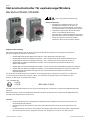 3
3
-
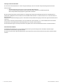 4
4
-
 5
5
-
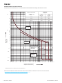 6
6
-
 7
7
-
 8
8
-
 9
9
-
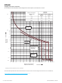 10
10
-
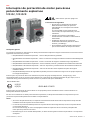 11
11
-
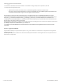 12
12
-
 13
13
-
 14
14
-
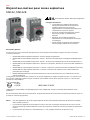 15
15
-
 16
16
-
 17
17
-
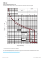 18
18
-
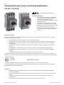 19
19
-
 20
20
-
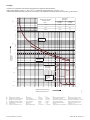 21
21
-
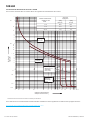 22
22
-
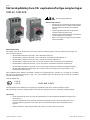 23
23
-
 24
24
-
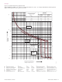 25
25
-
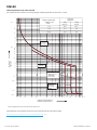 26
26
-
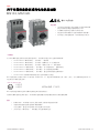 27
27
-
 28
28
-
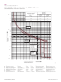 29
29
-
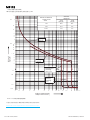 30
30
-
 31
31
-
 32
32
-
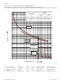 33
33
-
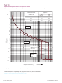 34
34
-
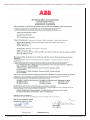 35
35
-
 36
36
-
 37
37
-
 38
38


ABB ATEX Instrucciones de operación
- Tipo
- Instrucciones de operación
en otros idiomas
- français: ABB ATEX Mode d'emploi
- italiano: ABB ATEX Istruzioni per l'uso
- English: ABB ATEX Operating instructions
- Deutsch: ABB ATEX Bedienungsanleitung
- русский: ABB ATEX Инструкция по эксплуатации
- svenska: ABB ATEX Bruksanvisningar
Artículos relacionados
Otros documentos
-
WIKA TR21-A tag:model:TR21-B tag:model:TR21-C Instrucciones de operación
-
-
-
Buhler CPsingle X1 Brief Instructions
-
-
-
-
WEG Electric motors for explosive atmospheres Manual de usuario
-
Siemens 3RB20 Operating Instructions Manual