
AKM
Deutsch Betriebsanleitung, Synchron Servomotoren
English Instructions Manual, Synchronous Servomotors
Italiano Manuale di istruzioni, Servomotori Sincroni
Español Manual de instrucciones, Servomotores Sincronos
Edition 04/2013
Originalsprache Deutsch
European Version (CE region)
File akm_deis.***
Bewahren Sie das Handbuch als Produktbestandteil während
der Lebensdauer des Produktes auf. Geben Sie das Handbuch
an nachfolgende Benutzer oder Besitzer des Produktes weiter.
Keep the manual as a product component during the life span of
the product. Pass the manual to future users / owners of the
product.
Conservare il manuale per l’intera durata del prodotto. In caso di
cambio di proprietà il manuale deve essere fornito al nuovo uti
-
lizzatore quale parte integrante del prodotto.
Conserve el manual durante toda la vida útil del producto.
Entregue el manual a posteriores usuarios o propietarios del
producto.

Record of Document Revisions
Revision Remarks
01 / 2009 First multilingual edition
06 / 2010
Appendix renamed to Drawings, AKM8 added, symbols according to ANSI Z535, Hiperface
added, minor corrections, technical data moved to appendix, new windings for AKM4 to 7,
radial-/axial force diagrams new for AKM1 to 8
10 / 2010 Transport tool order information, wiring diagrams updated for H connector
12 / 2010 Weight data AKM8, derating AKM8, DIN 748 => EN 50347, company name&address
04 / 2011 Washdown Variants, some minor corrections, climate categories, flange temperature limit
12 / 2011
EnDat encoders RoHS compliant, SFD combi connector option "D", GOST-R certificate, AKM8
dimensions corrected, AKM7 transport, Washdown Food
03 / 2012
AKM3: FRmax corrected, Washdown Food information extended, peak current/torque data
AKM1 to AKM7 updated
08 / 2012
AKM 1 extended options, wiring diagrams removed, connector pinout section added, KTY ther-
mal sensor version added, CE certificate, part number scheme extended
04 / 2013
Brake data, y-tec power pinout corrected, AKM 7 fan option, i-tec connector new, KTY thermal
sensor version updated
Technische Änderungen, die der Verbesserung der Geräte dienen, vorbehalten!
Originalbetriebsanleitung, gedruckt in der BRD
Alle Rechte vorbehalten. Kein Teil des Werkes darf in irgendeiner Form (Fotokopie, Mikrofilm oder in einem
anderen Verfahren) ohne schriftliche Genehmigung der Firma KOLLMORGEN Europe GmbH reproduziert
oder unter Verwendung elektronischer Systeme verarbeitet, vervielfältigt oder verbreitet werden.
Technical changes to improve the performance of the equipment may be made without prior notice!
Translation of the original manual, printed in the Federal Republic of Germany
All rights reserved. No part of this work may be reproduced in any form (by photocopying, microfilm or any
other method) or stored, processed, copied or distributed by electronic means without the written permission
of KOLLMORGEN Europe GmbH.
Il produttore si riserva la facoltà di apportare modifiche tecniche volte al miglioramento degli appa-
recchi
Traduzione del manuale originale, stampato nella Repubblica federale tedesca
Tutti i diritti riservati. Nessuna parte di questo documento può essere rielaborata, riprodotta in qualsiasi
forma (fotocopia, microfilm o altro processo) o diffusa mediante l'uso di sistemi elettronici senza l'approva-
zione scritta della ditta KOLLMORGEN Europe GmbH o rielaborata, riprodotta o diffusa mediante l’uso di sis-
temi elettronici.
Reservado el derecho de introducir modificaciones técnicas para la mejora de los equipos
Traducción del manual original, impreso en la RFA
Reservados todos los derechos. Prohibida la reproducción total o parcial de la presente obra por cualquier
medio (fotocopia, microfilm u otros), así como su procesamiento, reproducción y divulgación por medio de
sistemas electrónicos, sin expresa autorización escrita de la empresa KOLLMORGEN Europe GmbH.

tocdruck
1 Allgemeines
1.1 Über dieses Handbuch ............................................................9
1.2 Verwendete Symbole .............................................................9
1.3 Verwendete Abkürzungen .........................................................9
2Sicherheit
2.1 Das sollten Sie beachten .........................................................10
2.2 Bestimmungsgemäße Verwendung .................................................12
2.3 Nicht bestimmungsgemäße Verwendung ............................................12
2.4 Handhabung ...................................................................13
2.4.1 Transport .................................................................13
2.4.2 Verpackung ...............................................................14
2.4.3 Lagerung .................................................................14
2.4.4 Wartung / Reinigung ........................................................14
2.4.5 Reparatur.................................................................14
2.4.6 Entsorgung ...............................................................14
3 Produktidentifizierung
3.1 Lieferumfang...................................................................15
3.2 Typenschild....................................................................15
3.3 Typenschlüssel.................................................................16
3.3.1 Anschlussoptionen .........................................................17
3.3.2 Rückführeinheit ............................................................17
4 Technische Beschreibung
4.1 Allgemeine technische Daten......................................................18
4.2 Standardausrüstung .............................................................18
4.2.1 Bauform..................................................................18
4.2.2 Flansch ..................................................................18
4.2.3 Schutzart .................................................................18
4.2.4 Isolierstoffklasse ...........................................................19
4.2.5 Oberfläche................................................................19
4.2.6 Wellenende A-Seite.........................................................19
4.2.7 Schutzeinrichtung ..........................................................19
4.2.8 Schwinggüte ..............................................................19
4.3 Anschlusstechnik ...............................................................20
4.3.1 Stecker ..................................................................20
4.3.2 Kabelquerschnitte ..........................................................20
4.3.2.1 Leistungs-Kabel, Kombi-Kabel .............................................20
4.3.2.2 Feedback-Kabel ........................................................20
4.3.2.3 Hybrid-Kabel ...........................................................20
4.4 Haltebremse ...................................................................21
4.5 Lüfter für AKM7.................................................................21
4.6 Washdown und Washdown Food...................................................22
4.6.1 Washdown................................................................22
4.6.2 Washdown Food ...........................................................23
4.6.3 Geprüfte und bestätigte Eigenschaften gegenüber Reingungsmittel ...................23
4.6.4 Montage- und Einsatzbedingungen ............................................24
4.6.5 Reinigungsplan ............................................................24
5 Mechanische Installation
5.1 Wichtige Hinweise ..............................................................25
6 Elektrische Installation
6.1 Wichtige Hinweise ..............................................................26
6.2 Anschluss der Motoren mit vorkonfektionierten Kabeln..................................27
6.3 Leitfaden für die elektrische Installation ..............................................27
7 Inbetriebnahme
7.1 Wichtige Hinweise ..............................................................28
7.2 Leitfaden für die Inbetriebnahme ...................................................
29
7.3 Beseitigen von Störungen ........................................................30
8 Technische Daten
8.1 Begriffsdefinitionen ..............................................................31
Servomotoren AKM Deutsch - 3
Kollmorgen 04/2013 Inhaltsverzeichnis
Seite
DEUTSCH

9 General
9.1 About this manual...............................................................33
9.2 Symbols used ..................................................................33
9.3 Abbreviations used ..............................................................33
10 Safety
10.1 You should pay attention to this ....................................................34
10.2 Use as directed.................................................................36
10.3 Prohibited use..................................................................36
10.4 Handling ......................................................................37
10.4.1 Transport .................................................................37
10.4.2 Packaging ................................................................38
10.4.3 Storage ..................................................................38
10.4.4 Maintenance / Cleaning......................................................38
10.4.5 Repair ...................................................................38
10.4.6 Disposal..................................................................38
11 Package
11.1 Delivery package ...............................................................39
11.2 Nameplate ....................................................................39
11.3 Model number description ........................................................40
11.3.1 Connector Options .........................................................41
11.3.2 Feedback Options ..........................................................41
12 Technical Description
12.1 General technical data ...........................................................42
12.2 Standard features ...............................................................42
12.2.1 Style.....................................................................42
12.2.2 Flange ...................................................................42
12.2.3 Protection class ............................................................42
12.2.4 Insulation material class .....................................................43
12.2.5 Surface ..................................................................43
12.2.6 Shaft end, A-side...........................................................43
12.2.7 Protective device ...........................................................43
12.2.8 Vibration class .............................................................43
12.3 Wiring technology ...............................................................44
12.3.1 Connectors ...............................................................44
12.3.2 Wire cross sections .........................................................44
12.3.2.1 Power Cable, Combi Cable................................................44
12.3.2.2 Feedback Cable ........................................................44
12.3.2.3 Hybrid Cable ...........................................................44
12.4 Holding brake ..................................................................45
12.5 Fan for AKM7 ..................................................................45
12.6 Washdown and Washdown Food...................................................46
12.6.1 Washdown................................................................46
12.6.2 Washdown Food ...........................................................47
12.6.3 Tested and confirmed properties with respect to cleaning agents .....................47
12.6.4 Installation and operating conditions............................................48
12.6.5 Cleaning plan .............................................................48
13 Mechanical Installation
13.1 Important Notes ................................................................49
14 Electrical Installation
14.1 Important notes.................................................................50
14.2 Connection of the motors with preassembled cables....................................51
14.3 Guide for electrical installation .....................................................51
15 Setup
15.1 Important notes.................................................................52
15.2 Guide for setup .................................................................
53
15.3 Trouble Shooting ...............................................................54
16 Technical Data
16.1 Definition of Terms ..............................................................55
English - 4 Servomotors AKM
Contents 04/2013 Kollmorgen
Page
ENGLISH

17 Indicazoni generali
17.1 Questo manuale ................................................................57
17.2 Simboli utilizzati ................................................................57
17.3 Abbreviazioni utilizzati ...........................................................57
18 Sicurezza
18.1 Attenersi a queste indicazioni! .....................................................58
18.2 Uso conforme ..................................................................60
18.3 Uso conforme vietato ............................................................60
18.4 Maneggiamento ................................................................61
18.4.1 Trasporto .................................................................61
18.4.2 Imballaggio ...............................................................62
18.4.3 Stoccaggio................................................................62
18.4.4 Manutenzione / Puliza.......................................................62
18.4.5 Riparazioni................................................................62
18.4.6 Smaltimento...............................................................62
19 Identificazione del prodotto
19.1 Dotazione .....................................................................63
19.2 Targhetta di omologazione........................................................63
19.3 Codici dei modelli ...............................................................64
19.3.1 Opzioni di connettori ........................................................65
19.3.2 Unità di retroazione .........................................................65
20 Descrizione tecnizi
20.1 Dati tecnici generali .............................................................66
20.2 Allestimento standard ............................................................66
20.2.1 Forma costructtiva..........................................................66
20.2.2 Flangia...................................................................66
20.2.3 Grado di protezione.........................................................66
20.2.4 Classe di isolamento ........................................................67
20.2.5 Superficie ................................................................67
20.2.6 Estremità di uscita albero ....................................................67
20.2.7 Dispositivo di protezione .....................................................67
20.2.8 Resistenza alle vibrazioni ....................................................67
20.3 Sistema di collegamento .........................................................68
20.3.1 Connettore................................................................68
20.3.2 Sezioni dei cavi ............................................................68
20.3.2.1 Cavo di potenza, cavo combinato...........................................68
20.3.2.2 Cavo di retroazione......................................................68
20.3.2.3 Cavo ibrido ............................................................68
20.4 Freno di stazionamento ..........................................................69
20.5 Ventola per AKM7...............................................................69
20.6 Washdown e Washdown Food.....................................................70
20.6.1 Washdown................................................................70
20.6.2 Washdown Food ...........................................................71
20.6.3 Analisi e verifica delle proprietà nei confronti dei detergenti..........................71
20.6.4 Condizioni di montaggio e di utilizzo............................................72
20.6.5 Piano di pulizia ............................................................72
21 Installazione meccanica
21.1 Indicazioni importanti ............................................................73
22 Installazione elettrica
22.1 Indicazioni importanti ............................................................74
22.2 Collegamento dei motori con cavi preconfezionati......................................75
22.3 Guida ad installazione elettrica ....................................................75
23 Messa in funzione
23.1 Indicazioni importanti ............................................................76
23.2 Guida ad messa in funzione.......................................................
77
23.3 Eliminazione dei guasti...........................................................78
24 Dati tecnici
24.1 Definizioni .....................................................................79
Servomotori AKM Italiano - 5
Kollmorgen 04/2013 Sommario
Pagina
ITALIANO

25 Generalidades
25.1 Sobre este manual ..............................................................81
25.2 Símbolos utilizados..............................................................81
25.3 Abreviaturas utilizadas ...........................................................81
26 Seguridad
26.1 Siga sus instrucciones!...........................................................82
26.2 Utilización conforme .............................................................84
26.3 Uso indebido...................................................................84
26.4 Manipulación...................................................................85
26.4.1 Transporte ................................................................85
26.4.2 Embalaje .................................................................86
26.4.3 Almacenamiento ...........................................................86
26.4.4 Advertenzia / Limpieza ......................................................86
26.4.5 Reparación ...............................................................86
26.4.6 Eliminación ...............................................................86
27 Identificación del producto
27.1 Volumen de suministro ...........................................................87
27.2 Placa de identificación ...........................................................87
27.3 Codificación de modelo ..........................................................88
27.3.1 Opciones de conexión.......................................................89
27.3.2 Unidad de realimentación ....................................................89
28 Descripción técnica
28.1 Datos técnicos generales .........................................................90
28.2 Modelo estándar................................................................90
28.2.1 Forma de diseño ...........................................................90
28.2.2 Brida ....................................................................90
28.2.3 Tipo de protección..........................................................90
28.2.4 Clase de material aislante....................................................91
28.2.5 Superficie.................................................................91
28.2.6 Extremo del eje, lado de accionamiento .........................................91
28.2.7 Dispositivo protector ........................................................91
28.2.8 Calidad vibracional .........................................................91
28.3 Técnica de conexión.............................................................92
28.3.1 Enchufes .................................................................92
28.3.2 Secciones de cable .........................................................92
28.3.2.1 Cable de potencia, cable combinado ........................................92
28.3.2.2 Cable de Feedback......................................................92
28.3.2.3 Cable híbrido...........................................................92
28.4 Freno de detención..............................................................93
28.5 Ventilador para AKM7 ...........................................................93
28.6 Washdown y Washdown Food.....................................................94
28.6.1 Washdown................................................................94
28.6.2 Washdown Food ...........................................................95
28.6.3 Características probadas y confirmadas frente a productos de limpieza ................95
28.6.4 Condiciones de montaje y aplicación ...........................................96
28.6.5 Plan de limpieza ...........................................................96
29 Instalación mecánica
29.1 Instrucciones importantes ........................................................97
30 Instalación eléctrica
30.1 Instrucciones importantes.........................................................98
30.2 Conexión de los motores con conducciones preconfeccionadas ..........................99
30.3 Guía de instalación eléctrica ......................................................99
31 Puesta en funcionamento
31.1 Instrucciones importantes........................................................100
31.2 Guía de puesta en funcionamento .................................................
101
31.3 Eliminación de perturbaciones ....................................................102
32 Datos técnicos
32.1 Definiciones ..................................................................103
Español - 6 Servomotores AKM
Sumario 04/2013 Kollmorgen
Página
ESPAÑOL

33 Technical Data
33.1 Dictionary for technical data tables ................................................104
33.2 Technical Data AKM1...........................................................105
33.3 Technical Data AKM2...........................................................106
33.4 Technical Data AKM3...........................................................107
33.5 Technical Data AKM4...........................................................108
33.6 Technical Data AKM5...........................................................110
33.7 Technical Data AKM6...........................................................112
33.8 Technical Data AKM7 without fan .................................................114
33.9 Technical Data AKM7 with fan ....................................................115
33.10 Technical Data AKM8...........................................................116
34 Dimension drawings (Ax flanges)
34.1 Dimensions/Radial Forces AKM1..................................................117
34.1.1 Dimensions with cable connectors ............................................117
34.1.2 Dimensions with mounted Y-TEC connectors ...................................117
34.1.3 Radial Force .............................................................118
34.2 Dimensions/Radial Forces AKM2..................................................119
34.3 Dimensions/Radial Forces AKM3..................................................120
34.4 Dimensions/Radial Forces AKM4..................................................121
34.5 Dimensions/Radial Forces AKM5..................................................122
34.6 Dimensions/Radial Forces AKM6..................................................123
34.7 Dimensions/Radial Forces AKM7..................................................124
34.7.1 Dimensions standard motor .................................................124
34.7.2 Dimensions with mounted FAN kit ............................................125
34.7.3 Radial Force .............................................................126
34.8 Dimensions/Radial Forces AKM8..................................................127
34.8.1 Dimensions with terminal box ................................................127
34.8.2 Dimensions AKM82 with power connector ......................................128
34.8.3 Radial Force .............................................................129
35 Connector Pinout
35.1 Connector codes 1, Y: AKM1 .....................................................131
35.1.1 Power ..................................................................131
35.1.2 Resolver (Feedback code R-) ................................................131
35.1.3 SFD (Feedback code C-) ...................................................131
35.1.4 Encoder (Feedback codes GC, GD) ...........................................131
35.2 Connector codes 1, 2, 7, B, C, G, H, T: AKM1 - AKM8 .................................132
35.2.1 Power ..................................................................132
35.2.2 Resolver (Feedback code R-) ................................................133
35.2.3 SFD (Feedback code C-) ...................................................133
35.2.4 Encoder (Feedback codes Ax, Dx, Lx, Gx)......................................133
35.2.5 ComCoder (Feedback codes 1-, 2-) ...........................................133
35.3 Connector code D: AKM1 - AKM6 .................................................134
35.3.1 Power & SFD AKM1 (Feedback code C-).......................................134
35.3.2 Power & SFD AKM2 - AKM6 (Feedback code C-) ................................134
35.4 Connector code P: AKM1 - AKM4 .................................................135
35.4.1 Power & SFD.............................................................135
35.5 Connector code M: AKM1 - AKM4 .................................................135
35.5.1 Power ..................................................................135
35.5.2 Resolver (Feedback code R-) ................................................135
35.5.3 SFD (Feedback code C-) ...................................................135
35.5.4 Encoder (Feedback codes Ax, Dx, Lx, Gx)......................................136
35.5.5 ComCoder (Feedback codes 1-, 2-) ...........................................136
36 Approvals
36.1
Underwriters Laboratories .......................................................137
36.2 EC Declaration of Conformity.....................................................137
36.3 GOST-R certificate .............................................................138
Servomotors AKM General - 7
Kollmorgen 04/2013 Contents
Page

Diese Seite wurde bewusst leer gelassen.
Deutsch - 8 Servomotoren AKM
04/2013 Kollmorgen
DEUTSCH

1 Allgemeines
1.1 Über dieses Handbuch
Dieses Handbuch beschreibt die Synchron-Servomotoren der Serie AKM (Standardaus
-
führung). Die Motoren werden im Antriebssystem zusammen mit den Kollmorgen Servo
-
verstärkern betrieben. Beachten Sie daher die gesamte Dokumentation des Systems,
bestehend aus:
— Betriebsanleitung des Servoverstärkers
— Handbuch Bus-Kommunikation (z.B CANopen oder EtherCAT)
— Online Hilfe der Inbetriebnahmesoftware des Servoverstärkers
— Regionales Zubehörhandbuch
— Betriebsanleitung Motorserie AKM (dieses Handbuch)
Weitere Hintergundinformationen finden Sie im "Produkt-WIKI", erreichbar unter
www.wiki-kollmorgen.eu
.
1.2 Verwendete Symbole
Symbol Bedeutung
Weist auf eine gefährliche Situation hin, die, wenn sie
nicht vermieden wird, zum Tode oder zu schweren, irre-
versiblen Verletzungen führen wird.
Weist auf eine gefährliche Situation hin, die, wenn sie
nicht vermieden wird, zum Tode oder zu schweren, irre-
versiblen Verletzungen führen kann.
Weist auf eine gefährliche Situation hin, die, wenn sie
nicht vermieden wird, zu leichten Verletzungen führen
kann.
Dies ist kein Sicherheits-Symbol. Dieses Symbol weist
auf eine Situation hin, die, wenn sie nicht vermieden
wird, zu Beschädigung von Sachen führen kann.
Dies ist kein Sicherheits-Symbol. Dieses Symbol weist
auf wichtige Informationen hin.
Warnung vor einer Gefahr (allgemein). Die Art der
Gefahr wird durch den nebenstehenden Warntext spezifi-
ziert.
Warnung vor gefährlicher elektrischer Spannung und
deren Wirkung.
Warnung vor heißer Oberfläche.
Warnung vor hängenden Lasten.
1.3 Verwendete Abkürzungen
Siehe Kapitel 8.1 "Begriffsdefinitionen".
Servomotoren AKM Deutsch - 9
Kollmorgen 04/2013 Allgemeines
DEUTSCH

2 Sicherheit
Dieses Kapitel hilft Ihnen, Gefahren zu erkennen und zu vermeiden.
2.1 Das sollten Sie beachten
Dokumentation lesen
Lesen Sie vor der Montage und Inbetriebnahme die vorliegende Dokumentation. Fal-
sches Handhaben des Motors kann zu Personen- oder Sachschäden führen. Der Betrei-
ber muss daher sicherstellen, dass alle mit Arbeiten am Motor betrauten Personen das
Handbuch gelesen und verstanden haben und dass die Sicherheitshinweise in diesem
Handbuch beachtet werden.
Technische Daten beachten
Halten Sie die technischen Daten und die Angaben zu den Anschlussbedingungen
(Typenschild und Dokumentation) ein. Wenn zulässige Spannungswerte oder Stromwerte
überschritten werden, können die Motoren z.B. durch Überhitzung geschädigt werden.
Risikobeurteilung erstellen
Der Maschinenhersteller muss eine Risikobeurteilung für die Maschine erstellen und
geeignete Maßnahmen treffen, dass unvorhergesehene Bewegungen nicht zu Schäden
an Personen oder Sachen führen können. Aus der Risikobeurteilung leiten sich eventuell
auch zusätzliche Anforderungen an das Fachpersonal ab.
Fachpersonal erforderlich
Nur qualifiziertes Fachpersonal darf Arbeiten wie Transport, Montage, Inbetriebnahme
und Instandhaltung ausführen. Qualifiziertes Fachpersonal sind Personen, die mit Trans-
port, Aufstellung, Montage, Inbetriebnahme und Betrieb von Motoren vertraut sind und
über die ihrer Tätigkeit entsprechenden Mindestqualifikationen verfügen:
Transport: nur durch Personal mit Kenntnissen in der Behandlung
elektrostatisch gefährdeter Bauelemente
Mech. Installation: nur durch Fachleute mit maschinenbautechnischer Ausbildung
Elektr. Installation: nur durch Fachleute mit elektrotechnischer Ausbildung
Inbetriebnahme: nur durch Fachleute mit weitreichenden Kenntnissen in
den Bereichen Elektrotechnik / Antriebstechnik
Das Fachpersonal muss ebenfalls IEC 60364 / IEC 60664 und nationale Unfallverhü-
tungsvorschriften kennen und beachten.
Sicher transportieren
Heben und bewegen Sie Motoren mit mehr als 20kg Gewicht (AKM7 und AKM8) nur mit
Hilfe von Hebevorrichtungen. Heben ohne Hilfsmittel kann zu Rückenverletzungen füh-
ren. Beachten Sie die Hinweise auf Seite 13.
Passfeder sichern
Entfernen oder sichern Sie eine eventuell vorhandene Wellen-Passfeder, falls der Motor
ohne angekoppelte Last laufen soll, um ein Wegschleudern der Passfeder und die damit
verbundene Verletzungsgefahr zu vermeiden. Im Auslieferzustand ist die Passfeder mit
einer Kunststoffkappe gesichert.
Deutsch - 10 Servomotoren AKM
Sicherheit 04/2013 Kollmorgen
DEUTSCH

Heiße Oberfläche
Während des Betriebes können Motoren ihrer Schutzart entsprechend heiße Oberflächen
besitzen. Gefahr leichter Verbrennungen!
Die Oberflächentemperatur kann 100°C überschreiten. Messen Sie die Temperatur und
warten Sie, bis der Motor auf 40°C abgekühlt ist, bevor Sie ihn berühren.
Erdung
Stellen Sie die ordnungsgemäße Erdung des Motors mit der PE-Schiene im Schalt-
schrank als Bezugspotential sicher. Ohne niederohmige Erdung ist keine personelle
Sicherheit gewährleistet und es besteht Lebensgefahr durch elektrischen Schlag.
Hohe Spannungen
Halten Sie während des Betriebs der Geräte den Schaltschrank geschlossen. Das Fehlen
von optische Anzeigen gewährleisten nicht die Spannungsfreiheit. Leistungsanschlüsse
können Spannung führen, auch wenn sich der Motor nicht dreht.
Ziehen Sie keine Stecker während des Betriebs. Es besteht die Gefahr von Tod oder
schweren gesundheitlichen Schäden beim Berühren freiliegender Kontakte. In ungünsti-
gen Fällen können Lichtbögen entstehen und Personen und Kontakte schädigen.
Warten Sie nach dem Trennen der Servoverstärker von den Versorgungsspannungen
mehrere Minuten, bevor Sie spannungsführende Teile (z.B. Kontakte, Gewindebolzen)
berühren oder Anschlüsse lösen. Kondensatoren im Servoverstärker führen mehrere
Minuten nach Abschalten der Versorgungsspannungen gefährliche Spannungen. Messen
Sie zur Sicherheit die Spannung im Zwischenkreis und warten Sie, bis die Spannung
unter 40V abgesunken ist.
Hängende Lasten sichern
Eingebaute Haltebremsen sind nicht funktional sicher. Insbesondere bei hängender Last
(Vertikalachsen) kann die funktionale Sicherheit nur mit einer zusätzlichen, externen
mechanischen Bremse erreicht werden. Bei Nichtbeachtung kann
Servomotoren AKM Deutsch - 11
Kollmorgen 04/2013 Sicherheit
DEUTSCH

2.2 Bestimmungsgemäße Verwendung
—
Synchron-Servomotoren der Serie AKM sind insbesondere als Antrieb für Handha
-
bungsgeräte, Textilmaschinen, Werkzeugmaschinen, Verpackungsmaschinen und
ähnliche mit hohen Ansprüchen an die Dynamik konzipiert.
—
Sie dürfen die Motoren nur unter Berücksichtigung der in dieser Dokumentation de
-
finierten Umgebungsbedingungen betreiben.
— Der Betrieb von Washdown Motoren ist in Umgebungen mit ätzenden Säuren und
Laugen unter Berücksichtigung der im Kapitel 4.6 auf Seite 22 definierten Bedingun-
gen erlaubt.
— Der Betrieb von Washdown Food Motoren ist in Applikationen mit indirektem Kon-
takt zu Lebensmitteln erlaubt.
— Die Motoren der Serie AKM sind ausschließlich dazu bestimmt, von digitalen Ser-
voverstärkern drehzahl- und/oder drehmomentgeregelt angesteuert zu werden.
— Die Motoren werden als Bauteile in elektrische Anlagen oder Maschinen eingebaut
und dürfen nur als integrierte Bauteile der Anlage in Betrieb genommen werden.
— Der in die Motorwicklungen eingebaute Thermoschutzsensor muss ausgewertet und
überwacht werden.
— Eingebaute Haltebremsen sind als Stillstandsbremsen ausgelegt und für dauernde,
betriebsmäßige Abbremsvorgänge ungeeignet.
— Die Konformität des Servosystems zu den in der EG-Konformitätserklärung auf Sei-
te 13 genannten Normen garantieren wir nur, wenn von uns gelieferte Komponenten
(Servoverstärker, Motor, Leitungen usw.) verwendet werden.
2.3 Nicht bestimmungsgemäße Verwendung
— Der Betrieb von Standard Motoren ist verboten
- direkt am Netz,
- in explosionsgefährdeten Bereichen,
- im Kontakt mit Lebensmitteln,
- in Umgebungen mit ätzenden und/oder elektrisch leitenden Säuren, Laugen, Ölen,
Dämpfen, Stäuben.
— Der Betrieb von Washdown Motoren ist verboten
- direkt am Netz,
- in explosionsgefährdeten Bereichen,
- im Kontakt mit Lebensmitteln,
- in Umgebungen mit Säuren oder Laugen mit PH Wert kleiner 2 oder größer 12,
- in Umgebungen mit Säuren oder Laugen die nicht von Kollmorgen getestet wur-
den.
— Der Betrieb von Washdown Food Motoren ist verboten
- direkt am Netz,
- in explosionsgefährdeten Bereichen,
- im direkten Kontakt mit Lebensmitteln.
— Der bestimmungsgemäße Betrieb des Motors ist untersagt, wenn die Maschine, in
die er eingebaut wurde,
- nicht den Bestimmungen der EG Maschinenrichtlinie entspricht,
- nicht die Bestimmung der EMV-Richtlinie erfüllt,
- nicht die Bestimmung der Niederspannungs-Richtlinie erfüllt.
—
Eingebaute Haltebremsen alleine dürfen nicht für die Sicherstellung der funktionalen
Sicherheit benutzt werden.
Deutsch - 12 Servomotoren AKM
Sicherheit 04/2013 Kollmorgen
DEUTSCH

2.4 Handhabung
2.4.1 Transport
—
Klimaklasse 2K3 nach EN61800-2, IEC 60721-3-2
—
Temperatur: -25..+70°C, max. 20K/Stunde schwankend
Luftfeuchtigkeit: relative Feuchte 5% ... 95% nicht kondensierend
— Nur von qualifiziertem Personal in der Original-Verpackung des Herstellers
— Vermeiden Sie harte Stöße, insbesondere auf das Wellenende
— Überprüfen Sie bei beschädigter Verpackung den Motor auf sichtbare Schäden. In-
formieren Sie den Transporteur und gegebenenfalls den Hersteller.
Transport von Motoren über 20kg Gewicht
Verwenden Sie für den sicheren Transport der Motoren AKM7 und AKM8 (>20kg) die
beiliegenden Hebeösen.
Beachten Sie die in der Motorverpackung beiliegende Anweisungen für den Transport.
Als Zubehör zum Transport der Motoren empfehlen wir die Transportvorrichtung ZPMZ
120/292.
Die Transportvorrichtung ZPMZ 120/292 besteht aus einer Traverse, die am Kranhaken
eingehängt wird und zwei zweiadrigen Kettenanschlägen.
Schwebende Last. Lebensgefahr wenn die Last abstürzt.
Treten Sie während des Hebevorgangs niemals unter die Last!
— die Befestigungsschrauben der Hebeösen müssen vollständig eingedreht sein
— die Hebeösen müssen eben und vollflächig auf der Auflagefläche aufliegen
— Die Hebeösen vor dem Gebrauch auf festen Sitz und augenfällige Beschädigungen
(Korrosion, Verformung) überprüfen.
— Hebeösen mit Verformungen dürfen nicht weiterbenutzt werden.
Servomotoren AKM Deutsch - 13
Kollmorgen 04/2013 Sicherheit
DEUTSCH

2.4.2 Verpackung
—
Kartonverpackung mit Instapak
®
-Ausschäumung.
—
Den Kunststoffanteil können Sie an den Lieferanten zurückgeben
Motortyp Verpackung
max. Stapel
-
höhe
Motortyp Verpackung
max. Stapel
-
höhe
AKM1 Karton 10 AKM5 Karton 5
AKM2 Karton 10 AKM6 Karton 1
AKM3 Karton 6 AKM7 Karton 1
AKM4 Karton 6 AKM8 Mini-Palette 1
2.4.3 Lagerung
— Klimaklasse 1K4 nach EN61800-2, IEC 60721-3-2
— Lagertemperatur -25...+55°C, max. 20K/Stunde schwankend
— Luftfeuchtigkeit relative Feuchte 5% ... 95% nicht kondensierend
— Nur in der Originalverpackung des Herstellers lagern
— Max. Stapelhöhe: siehe Tabelle in Kapitel "Verpackung"
— Lagerdauer: ohne Einschränkung
2.4.4 Wartung / Reinigung
— Wartung und Reinigung nur von qualifiziertem Personal
— Nach 20.000 Betriebsstunden unter Nennbedingungen sollten die Kugellager erneu-
ert werden (vom Hersteller).
— Prüfen Sie den Motor alle 2500 Betriebsstunden bzw. einmal jährlich auf Kugellager-
geräusche. Wenn Sie Geräusche feststellen, darf der Motor nicht weiterbetrieben
werden - die Lager müssen erneuert werden (vom Hersteller).
— Öffnen der Motoren bedeutet den Verlust der Gewährleistung.
— Gehäusereinigung mit Isopropanol o.ä., nicht tauchen oder absprühen
2.4.5 Reparatur
Reparaturen des Motors darf nur der Hersteller durchführen, Öffnen der Geräte bedeutet
Verlust der Gewährleistung. Schicken Sie den Motor zur Reparatur an:
KOLLMORGEN Europe GmbH
Pempelfurtstr. 1
D-40880 Ratingen
2.4.6 Entsorgung
Gemäß der WEEE-2002/96/EG-Richtlinien nehmen wir Altgeräte und Zubehör zur fach-
gerechten Entsorgung zurück, sofern die Transportkosten vom Absender übernommen
werden. Senden Sie die Geräte an:
KOLLMORGEN Europe GmbH
Pempelfurtstr. 1
D-40880 Ratingen
Deutsch - 14 Servomotoren AKM
Sicherheit 04/2013 Kollmorgen
DEUTSCH

3 Produktidentifizierung
3.1 Lieferumfang
Sie erhalten einen Karton mit Instapak
®
-Ausschäumung. Enthalten ist:
— Motor der Serie AKM
— Produkthandbuch gedruckt, mehrsprachig, einmal pro Lieferung
3.2 Typenschild
Bei Standardmotoren ist das Typenschild unverlierbar seitlich auf das Gehäuse geklebt.
Bei Washdown Motoren ist das Typenschild seitlich in das Gehäuse eingraviert, je
Verpackungseinheit liegt ein zusätzliches Typenschild bei.
Legende:
MODEL Typenbezeichnung
CUST P/N Kunden-Mat.Nr
Ics I
0rms
(Stillstandsstrom)
Tcs M
0
(Stillstandsdrehmoment)
Vs U
n
(Zwischenkreisspannung)
Nrtd nn (Nenndrehzahl bei U
n
)
Prtd Pn (Nennleistung)
Rm R25 (Wicklungswiderstand bei 25°)
SERIAL Seriennummer
AMBIENT zul. Umgebungstemp.
Das Baujahr des Motors ist in der Seriennummer kodiert: die ersten beiden Ziffern der
Seriennummer bezeichnen das Jahr, z.B. bedeutet "12" 2012.
Servomotoren AKM Deutsch - 15
Kollmorgen 04/2013 Produktidentifizierung
DEUTSCH
E61960
PS155-1
EN60034-1
EN60034-5
MODEL:
Cust P/N:
Ics Arms
Tcs Nm
Vs V DC
Nrtd RPM
Prtd kW
Rm OHMS (L-L) 25 °C
SERIAL #
Ambient 40 °C IP
Made in Czech Republic BCZ www.Kollmorgen.com

3.3 Typenschlüssel
Deutsch - 16 Servomotoren AKM
Produktidentifizierung 04/2013 Kollmorgen
DEUTSCH
AKM 6 2 P -AN C N DA 00
Flanschgröße
1 40mm
2 58mm
3 70mm
4 84mm
5 108mm
6 138mm
7 188mm
8 260mm
Flansch
A IEC mit Toleranz N
B NEMA
R IEC mit Toleranz R
M,T verstärkte Lager AKM8
W Flanschbeschichtung
für Washdown, IEC
S sonder
C, D, G, H sind alternative
Flanschvarianten. Kontaktieren
Sie den Kollmorgen Vertrieb.
Rotorlänge
1
2
3
4
5
Wicklungstyp
A..Z
S sonder
Anschlüsse
alle Typen siehe Seite 17
S sonder
Bremse
2 24V Haltebremse
N ohne Bremse
S sonder
Rückführeinheit
alle Typen siehe Seite 17
S- sonder
Ausführung
00 Standard
01 mit Wellendichtring
0W Washdown
0F Washdown Food
Welle
C Passfedernut
K offene Passfedernut
N glatte Welle
S sonder

3.3.1 Anschlussoptionen
Die Steckerbelegungen für die Optionen finden Sie ab S.131.
Code
PTC
KTY
84-130
Verwendbar mit Bezeichnung Steckerposition
B 1 AKM2
Zwei IP65 Stecker Gr. 1.0
abgewinkelt, drehbar
auf Motor montiert
C 7 AKM1 - AKM2 Zwei IP65 Stecker Gr. 1.0 an 0,5m Kabel
C 1 AKM3 - AKM7
Zwei IP65 Stecker Gr. 1.0 abgewin-
kelt, drehbar
auf Motor montiert
D - AKM1, SFD, ohne Bremse Ein IP65 Hybridstecker i-tec auf Motor montiert
D-
AKM2 - AKM6, SFD ohne
Bremse
Ein IP65 Hybridstecker Gr. 1.0,
abgewinkelt, drehbar
auf Motor montiert
G - AKM2 - AKM6 Zwei gerade IP65 Stecker Gr. 1.0 auf Motor montiert
H 1 AKM74Q & AKM82T
Ein IP65 Feedback Stecker Gr.1.0,
ein IP65 Leistungsstecker Gr. 1.5
auf Motor montiert
M - AKM1 - AKM4 Zwei IP20 Molex Stecker, Io<6A an 0,5m Kabel
P-
AKM1 - AKM4, SFD,
ohne Bremse
Ein IP20 Molex Hybridstecker, Io<6A an 0,5m Kabel
T 2 AKM8
Klemmkasten IP65 für Leistung,
ein IP65 Feedback Stecker Gr. 1.0
auf Motor montiert
Y 1 AKM1 IP65, y-tec Stecker auf Motor montiert
3.3.2 Rückführeinheit
Die Motorlänge hängt von der eingebauten Rückführeinheit (Feedback) ab, siehe Maß-
zeichnungen ab Seite 117. Ein nachträglicher Einbau ist nicht möglich. Die Steckerbele-
gungen für die Optionen finden Sie im Kapitel "Connector Pinout" ab S.131.
Code Bezeichnung Modell Verwendbar mit Bemerkung
1- Comcoder AKM1 - AKM8 1024 Inkr/U
2- Comcoder AKM1 - AKM8 2048 Inkr/U
AA BiSS B Encoder AD36 AKM2 - AKM4 Single-turn, optisch
AA BiSS B Encoder AD58 AKM5 - AKM8 Single-turn, optisch
AB BiSS B Encoder AD36 AKM2 - AKM4 Multi-turn, optisch
AB BiSS B Encoder AD58 AKM5 - AKM8 Multi-turn, optisch
C- SFD Size 10 AKM1 Gen2, Single-turn
C- SFD Size 15 AKM2 - AKM4 Gen2, Single-turn
C- SFD Size 21 AKM5 - AKM8 Gen2, Single-turn
DA EnDAT 2.1 Encoder ECN 1113 AKM2 - AKM4 Single-turn, optisch
DA EnDAT 2.1 Encoder ECN 1313 AKM5 - AKM8 Single-turn, optisch
DB EnDAT 2.1 Encoder EQN 1125 AKM2 - AKM4 Multi-turn, optisch
DB EnDAT 2.1 Encoder EQN 1325 AKM5 - AKM8 Multi-turn, optisch
LA EnDAT 2.1 Encoder ECI 1118 AKM2 - AKM3 Single-turn, induktiv
LA EnDAT 2.1 Encoder ECI 1319 AKM4 - AKM8 Single-turn, induktiv
LB EnDAT 2.1 Encoder EQI 1130 AKM2 - AKM3 Multi-turn, induktiv
LB EnDAT 2.1 Encoder EQI 1331 AKM4 - AKM8 Multi-turn, induktiv
GA* HIPERFACE Encoder SKS36 AKM2 - AKM8 Single-turn
GB* HIPERFACE Encoder SKM36 AKM2 - AKM8 Multi-turn
GC HIPERFACE Encoder SEK34 AKM1 Single-turn, kapazitiv
GD HIPERFACE Encoder SEL34 AKM1 Multi-turn, kapazitiv
R- Resolver Size 10 AKM1 2 polig, Hohlwelle
R- Resolver Size 15 AKM2 - AKM4 2 polig, Hohlwelle
R- Resolver Size 21 AKM5 - AKM8 2 polig, Hohlwelle
* nicht verfügbar bei AKM2 mit Anschlussoption "C" (Kabel mit IP65 Stecker)
Servomotoren AKM Deutsch - 17
Kollmorgen 04/2013 Produktidentifizierung
DEUTSCH

4 Technische Beschreibung
4.1 Allgemeine technische Daten
Umgebungstemperatur 5...+40°C bei Aufstellhöhe bis 1000m über NN
(bei Nenndaten) Sprechen Sie bei Umgebungstemperaturen über 40°C
und bei gekapseltem Einbau der Motoren unbedingt mit
unserer Applikationsabteilung.
Zulässige Luftfeuchte 95% relative Feuchte, nicht betauend
(bei Nenndaten)
Leistungsreduzierung 1%/K im Bereich 40°C...50°C bis 1000m über NN
(Ströme und Momente) Bei Aufstellhöhen über 1000m über NN und 40°C
6% bei 2000m über NN
17% bei 3000m über NN
30% bei 4000m über NN
55% bei 5000m über NN
Keine Leistungsreduzierung bei Aufstellhöhen über
1000m über NN und Temperaturreduzierung
um 10K / 1000m
Kugellager-Lebensdauer ³ 20.000 Betriebsstunden
Technische Daten der Motortypen finden Sie im Kapitel "Technical Data" ab S.104.
4.2 Standardausrüstung
4.2.1 Bauform
Die Grundbauform der Synchron-Servomotoren AKM ist die Bauform IM B5 nach DIN EN
60034-7.
4.2.2 Flansch
Flanschmaße nach IEC-Norm, Passung j6 (AKM1: h7), Genauigkeit nach DIN 42955
Toleranzklasse : N, optional R für IEC Flansch
Maximal zulässige Flanschtemperatur im Dauerbetrieb: 65°C
4.2.3 Schutzart
Standardmotor Anschlusscode Wellendichtring Schutzart
AKM1-4 M, P mit oder ohne IP20
AKM1 C, D ohne IP40
AKM1 C, D mit IP65
AKM2-AKM8 B, C, D, G, H, T ohne IP54
AKM2-AKM8 B, C, D, G, H, T mit IP65
Deutsch - 18 Servomotoren AKM
Technische Beschreibung 04/2013 Kollmorgen
DEUTSCH

4.2.4 Isolierstoffklasse
Die Motoren entsprechen der Isolierstoffklasse F nach IEC 60085 (UL 1446 class F).
4.2.5 Oberfläche
Die Motoren sind mattschwarz mit Polyester pulverbeschichtet, eine Beständigkeit gegen
Lösungsmittel (Tri, Verdünnung o.ä.) besteht nicht.
4.2.6 Wellenende A-Seite
Die Kraftübertragung erfolgt über das zylindrische Wellenende A, Passung k6 (AKM1: h7)
nach EN50347 mit Anzugsgewinde aber ohne Passfedernut. Für die Lebensdauer der
Lager sind 20.000 Betriebsstunden zugrunde gelegt.
Radialkraft
Treiben die Motoren über Ritzel oder Zahnriemen an, so treten hohe Radialkräfte auf.
Die zugelassenen Werte am Wellenende abhängig von der Drehzahl entnehmen Sie den
Diagrammen im Kapitel "Drawings" ab S.117. Die zugelassenen Maximalwerte finden Sie
in den technischen Daten. Bei Kraftangriff an der Mitte des freien Wellenendes kann F
R
10% größer sein.
Axialkraft
Bei der Montage von Ritzel oder Riemenscheiben auf die Welle und bei Betrieb von z.B.
Winkelgetrieben treten Axialkräfte auf. Die zugelassenen Maximalwerte finden Sie in den
technischen Daten.
Kupplung
Als ideale spielfreie Kupplungselemente haben sich doppelkonische Spannzangen even-
tuell in Verbindung mit Metallbalg-Kupplungen bewährt.
4.2.7 Schutzeinrichtung
In der Standardausführung ist jeder Motor mit einem potentialfreien PTC Temperatursen-
sor ausgestattet. Der Schaltpunkt liegt bei 155°C ± 5%. Schutz gegen kurzzeitige, sehr
hohe Überlastung bietet der PTC nicht.
Optional kann der Motor mit einem KTY 84-130 Sensor ausgerüstet werden (siehe
Anschlussoption 1, 2 und 7 auf Seite 17).
Der Sensor ist bei Verwendung unserer vorkonfektionierten Feedbackleitungen in das
Überwachungssystem der digitalen Servoverstärker integriert.
4.2.8 Schwinggüte
Die Motoren sind in Schwinggüte A nach EN 60034-14 ausgeführt. Das bedeutet für
einen Drehzahlbereich von 600-3600 U/min und einer Achshöhe zwischen 56-132mm
eine zulässige Schwingstärke von 1,6mm/s als Effektivwert.
Drehzahl [U/min] max. rel. Schwingweg [µm] max. Run-out [µm]
<= 1800 90 23
> 1800 65 16
Servomotoren AKM Deutsch - 19
Kollmorgen 04/2013 Technische Beschreibung
DEUTSCH

4.3 Anschlusstechnik
4.3.1 Stecker
Stecker
Polzahl max. Strom max. Querschnitt
Power Signal Power Signal Power Signal
IP65 Leistungs-Stecker Größe 1,0
4 4 30 A 10 A 4 mm² 1,5 mm²
IP65 Leistungs-Stecker Größe 1,5
4 2 75 A 30 A 16 mm² 4 mm²
IP20 Leistungs-Stecker Molex
4 / 8 13 A 1,5 mm²
IP65 Leistungs-Stecker y-tec
4 5 14 A 3,6 A 1,5 mm² 0,75 mm²
IP65 Resolver-Stecker
- 12 - 10 A - 0,5 mm²
IP65 Encoder-Stecker
- 17 - 9 A - 0,5 mm²
IP20 Feedback-Stecker Molex
- 10 / 18 13 A 1,5 mm²
IP65 Feedback-Stecker y-tec
- 12 - 5 A - 0,75 mm²
IP65 Hybrid-Stecker Größe 1,0
4 4 30 A 10 A 4 mm² 1,5 mm²
IP20 Hybrid-Stecker Molex
10 13 A 1,5 mm²
IP65 Hybrid-Stecker i-tec
4 5 14 A 3,6 A 1,5 mm² 0,75 mm²
IP65 Klemmkasten
4 2 150 A 15 A 25 mm² 2,5 mm²
4.3.2 Kabelquerschnitte
4.3.2.1 Leistungs-Kabel, Kombi-Kabel
Kombikabel enthalten neben den 4 Leistungsadern zwei abgeschirmte Bremsadern.
Querschnitt
Strombelastbarkeit
Bemerkung
Kabel Kombi-Kabel
(4x1) (4x1+(2x0,75))
0A<I
0rms
£ 10,1A
Die Klammern (...) deuten
die Abschirmungen an.
Strombelastbarkeit gem.
EN60204-1:2006
Tabelle 6, Spalte B2
(4x1,5) (4x1,5+(2x0,75))
10,1A < I
0rms
£ 13,1A
(4x2,5) (4x2,5+(2x1))
13,1A < I
0rms
£ 17,4A
(4x4) (4x4+(2x1))
17,4 < I
0rms
£ 23A
(4x6) (4x6+(2x1))
23<I
0rms
£ 30A
(4x10) (4x10+(2x1,5))
30<I
0rms
£ 40A
(4x16) (4x16+(2x1,5))
40<I
0rms
£ 54A
(4x25) (4x25+(2x1,5))
54<I
0rms
£ 70A
4.3.2.2 Feedback-Kabel
Typ Querschnitt Bemerkung
Resolver, SFD (4x2x0,25)
Encoder (7x2x0,25) BiSS, EnDAT, HIPERFACE
Comcoder (8x2x0,25) Inkrementalgeber+Hall
4.3.2.3 Hybrid-Kabel
Typ Querschnitt Bemerkung
Hybrid
(4x1,0+2x(2x0,75))
4 Leistungsadern und 4 Signaladern für
SFD Gen2
(4x1,5+2x(2x0,75))
Deutsch - 20 Servomotoren AKM
Technische Beschreibung 04/2013 Kollmorgen
DEUTSCH

4.4 Haltebremse
Die Motoren sind wahlweise mit eingebauter Haltebremse erhältlich.
Die Federdruckbremse (24V DC) blockiert im spannungslosen Zustand den Rotor.
Die Motorlänge vergrößert sich bei eingebauter Haltebremse.
Wenn bei hängender Last (Vertikalachsen) die Motorhaltebremse gelöst
ist und gleichzeitig der Servoantrieb keine Leistung erbringt, kann die
Last herunterfallen!
Verletzungsgefahr für das Bedienpersonal der Maschine.
Die funktionale Sicherheit kann bei vertikalen Achsen nur mit einer
zusätzlichen, externen mechanischen Bremse erreicht werden.
Die Haltebremsen sind als Stillstandsbremsen ausgelegt und für dauernde, betriebsmäßi-
ge Abbremsvorgänge ungeeignet. Bei häufiger betriebsmäßiger Abbremsung ist ein vor-
zeitiger Verschleiß und Ausfall der Haltebremse wahrscheinlich.
Die Haltebremsen können direkt vom Servoverstärker angesteuert werden (nicht perso-
nell sicher!), dann erfolgt das Löschen der Bremswicklung im Servoverstärker — eine
zusätzliche Beschaltung ist nicht erforderlich. Beachten Sie hierzu die Betriebsanleitung
des Servoverstärkers.
Wird die Haltebremse nicht vom Servoverstärker direkt angesteuert, muss eine zusätzli-
che Beschaltung (z.B. Varistor) vorgenommen werden. Sprechen Sie hierzu mit unserem
Kundendienst.
4.5 Lüfter für AKM7
Für die Baugröße AKM7 ist ein Anbausatz zur Fremdbelüftung verfügbar. Der eingebaute
Lüfter ermöglicht bis zu 30% höhere Leistungsabgabe der AKM7 Motoren. Eine Montage-
anweisung für den Lüfterbausatz ist im Lieferumfang des Anbausatzes enthalten.
Das Lüftergehäuse kann entweder nur mit den mit-
gelieferten Befestigungswinkeln oder zusätzlich mit
den ebenfalls mitgelieferten Abstandsbolzen
befestigt werden. Die Wahl der Befestigungsme-
thode hängt ab von der Applikation. Ist mit starken
Vibrationen zu rechnen, benutzen Sie zur Sicher-
heit Winkel und Abstandsbolzen. Motoren mit ein-
gebauter Bremse erfordern die langen Abstands-
bolzen.
Sorgen Sie für freie Luftzufuhr am Lüftergitter und halten Sie einen Freiraum von minde-
stens 25mm hinter dem Lüftergitter ein.
Durch die erzwungene Konvektion verschmutzen die Motoren deutlich stärker. Schmutz-
ablagerungen führen zu sinkender Kühlleistung und können die Motoren gefährden.
Staubablagerungen können bei Überhitzung entflammen. Reinigen Sie daher in regelmä-
ßigen Abständen die Luftführung, den Lüfter und die Motoren.
Durch den Lüfteranbau erhöhen sich die Einbaumaße der AKM7 Motoren.
Technische Daten der AKM7 Motoren mit Lüfter finden Sie auf Seite 115.
Die Maßzeichnung der AKM7 Motoren mit Lüfter finden Sie auf Seite 125.
Servomotoren AKM Deutsch - 21
Kollmorgen 04/2013 Technische Beschreibung
DEUTSCH

4.6 Washdown und Washdown Food
Diese Motorvarianten werden in Applikationen eingesetzt, die strengen hygienischen Vor
-
schriften unterliegen, in denen es Keimbildung und Korrosion zu vermeiden gilt und in
denen Maschinen zyklisch gereinigt werden müssen.
Die Motoren basieren auf den Standardtypen AKM2 - AKM6 mit speziellen Veränderun-
gen für den Einsatz in der Lebensmittel verarbeitenden Industrie oder auch in der Verpa-
ckungsindustrie. Zusätzlich gibt es jeweils die Möglichkeit, auch den Flansch zu
beschichten - dann kann die Toleranzklasse N für den Flansch allerdings nicht gewähr-
leistet werden.
Im Typenschlüssel ist die Lackierung des Motorgehäuses (Typen "W" für Washdown, "F"
für Wasdown Food) in der Ausführung (letzten zwei Stellen) und die Flanschbeschichtung
getrennt definiert.
4.6.1 Washdown
AKM^^^-^^^^^-^W Washdown Lackierung ohne Flanschbeschichtung
AKM^^^-W^^^^-^W Washdown mit Flanschbeschichtung des IEC A-Flansch
Die Washdown Motoren dürfen keinen Kontakt zu unverpackten Lebensmitteln haben.
Einsatzgebiet:
Raue Umgebungen, Außenbereiche
Beispiel
Transport im Bereich Lebensmittel und Verpackung ohne Kontakt zu
Lebensmitteln, Radarstationen, Windturbinen, Offshore Anlagen
Standards
UL, CE, RoHs
Oberfläche:
silberne Beschichtung
Beständigkeit
Gegen geprüfte Reinigungsmittel (siehe Seite 23), korrosionsfest
Schutzart:
IP67
Welle:
Edelstahl
Wellendichtring:
PTFE
Schmiermittel:
industrielles Lagerschmierfett, nicht lebensmitteltauglich
Stecker:
Edelstahl, glatte Oberfläche
Schrauben:
Edelstahl
Typenschild:
Eingraviert, je Verpackungseinheit ein zusätzliches Typenschild
Baugröße:
AKM2 - AKM6
Deutsch - 22 Servomotoren AKM
Technische Beschreibung 04/2013 Kollmorgen
DEUTSCH

4.6.2 Washdown Food
AKM^^^-^^^^^^-^F Washdown Food Lackierung ohne Flanschbeschichtung
AKM^^^-W^^^^^-^F Washdown Food mit Flanschbeschichtung des IEC A-Flansch
Die Oberfläche des Washdown Food Motoren hat alle Tests gemäß FDA
GlobalMigration für indirekten Kontakt zu Lebensmitteln bestanden. Ein direkter Kontakt
zu unverpackten Lebensmitteln ist nicht zulässig.
Einsatzgebiet:
Lebensmittel- und Getränkeindustrie,
kein direkter Kontakt mit unverpackten Lebensmitteln.
Beispiel
Schneiden, Verpacken und Füllen ohne direkten Kontakt zum
Lebensmittel, Motor seitlich oder unter dem Lebensmittel.
Standards
UL, CE, RoHs, FDA
Oberfläche:
weiße Beschichtung
Beständigkeit
Gegen geprüfte Reinigungsmittel (siehe Seite 23), korrosionsfest
Schutzart:
IP67
Welle:
Edelstahl
Wellendichtring:
PTFE, gemäß FDA
Schmiermittel:
Lebensmitteltauglich, gemäß FDA
Stecker:
Edelstahl, glatte Oberfläche
Schrauben:
Edelstahl
Typenschild:
Eingraviert, je Verpackungseinheit ein zusätzliches Typenschild
Baugröße:
AKM2 - AKM6
4.6.3 Geprüfte und bestätigte Eigenschaften gegenüber Reingungsmittel
Im Prüflabor der ECOLAB Deutschland GmbH wurde die Resistenz der Washdown und
Washdown Food Oberflächen gegen folgende industrielle Reinigungsmittel geprüft:
— P3-topactive DES
— P3-topactive LA
— P3-topax 56
— P3-topax 66
— P3-topax 91
Dabei wurden die Oberflächen 28 Tage lang bei Raumtemperatur in das jeweilige Reini-
gungsmittel getaucht.
Dies entspricht ca. 2500 Reingungszyklen mit jeweils 15 minütigem Kontakt zum Reini-
gungsmittel bzw. 1500 Reinigungszyklen mit Reinigung und nachfolgender Desinfektion.
Die Zertifikate finden Sie in unserem Produkt-WIKI auf der Seite Zulassungen
.
Kollmorgen kann eine Gewährleistung der Motorlebensdauer nur bei Einsatz der geteste-
ten Reinigungsmittel geben. Andere als die oben genannten Reinigungsmittel kann
Kollmorgen auf Anfrage testen und gegebenfalls freigeben.
Servomotoren AKM Deutsch - 23
Kollmorgen 04/2013 Technische Beschreibung
DEUTSCH

4.6.4 Montage- und Einsatzbedingungen
—
Die Motoren dürfen nur bei Umgebungstemperaturen bis maximal 50°C eingesetzt
werden.
—
Bei beschichtetem Vorderflansch ist die Toleranzklasse N nicht gewährleistet.
Bei Motoren mit Flanschen ohne Washdown Beschichtung muss die Flanschfläche durch
geeignete Montage vor dem Einfluss von Reinigungsmitteln geschützt werden.
4.6.5 Reinigungsplan
Empfohlener Reinigungsplan (Kurzform) mit den getesteten Reinigungsmitteln:
Spülen mit Wasser (40°... 50°C)
Spülen mit niedrigem Druck. Von oben nach unten in Richtung zum Abfluss. Den Abfluss
reinigen.
Schaumreinigung
Schäumen von oben nach unten.
Alkalisch: P3-topactive LA oder P3-topax 66 (2-5%, täglich 15 min)
Sauer: P3-topax 56 (2%, wenn erforderlich 15 min)
Temperatur: kalt bis zu 40°C
Desinfektion
Absprühen mit Wasser (40°... 50°C) mit niedrigem Druck. Von oben nach unten.
Sprühdesinfektion: P3-topax 91 (1-2%, wenn erforderlich 30-60 min)
Schaumdesinfektion: P3-topactiv DES (1-3%, wenn erforderlich 10-30 min)
Deutsch - 24 Servomotoren AKM
Technische Beschreibung 04/2013 Kollmorgen
DEUTSCH

5 Mechanische Installation
Maßzeichnungen finden Sie im Kapitel "Dimension Drawings" ab S.117.
5.1 Wichtige Hinweise
Nur Fachleute mit Maschinenbau-Kenntnissen dürfen den Motor montieren.
— Schützen Sie die Motoren vor unzulässiger Beanspruchung. Bei Transport und
Handhabung dürfen keine Bauelemente beschädigt werden.
— Der Einbauort muss frei von leitfähigen und aggressiven Stoffen sein.
Bei V3-Montage (Wellenende nach oben), darf keine Flüssigkeit in die Lager ein-
dringen. Bei gekapseltem Einbau sprechen Sie zunächst mit unserer Applikations-
abteilung.
— Stellen Sie die ungehinderte Belüftung der Motoren sicher und beachten Sie die zu-
lässige Umgebungs- und Flanschtemperatur. Bei Umgebungstemperaturen über
40°C sprechen Sie mit unserer Applikationsabteilung. Sorgen Sie für ausreichende
Wärmeabfuhr in der Umgebung und am Motorflansch, um die maximal zulässige
Flanschtemperatur von 65°C im S1-Betrieb nicht zu überschreiten.
— Servomotoren sind Präzisionsgeräte. Insbesondere Flansch und Welle sind bei La-
gerung und Einbau gefährdet — vermeiden Sie daher rohe Kraftanwendung. Benut-
zen Sie zum Aufziehen von Kupplungen, Zahnrädern oder Riemenscheiben unbe-
dingt das vorgesehene Anzugsgewinde in der Motorwelle und erwärmen Sie, sofern
möglich, die Abtriebselemente. Schläge oder Gewaltanwendung führen zur Schädi-
gung von Kugellagern und Welle.
— Verwenden Sie nach Möglichkeit nur spielfreie, reibschlüssige Spannzangen oder
Kupplungen. Achten Sie auf korrektes Ausrichten der Kupplung. Ein Versatz führt zu
unzulässigen Vibrationen und zur Zerstörung von Kugellagern und Kupplung.
— Vermeiden Sie unter allen Umständen eine mechanisch überbestimmte Lagerung
der Motorwelle durch starre Kupplung und externe Lagerung (z.B. im Getriebe).
— Beachten Sie die Motorpolzahl und die Resolverpolzahl und stellen Sie bei den ver-
wendeten Servoverstärkern die Polzahlen unbedingt korrekt ein. Falsche Einstellung
kann besonders bei kleinen Motoren zur Zerstörung führen.
—
Vermeiden Sie möglichst eine axiale Belastung der Motorwelle. Eine axiale Bela
-
stung verkürzt die Lebensdauer des Motors erheblich.
—
Prüfen Sie die Einhaltung der zulässigen Radial- und Axialbelastungen F
R
und F
A
.
Bei Verwendung eines Zahnriemen-Antriebs ergibt sich der minimal zulässige
Durchmesser des Ritzels z.B. nach der Gleichung:
dMF
Rmin
(/)³´
0
2
.
Servomotoren AKM Deutsch - 25
Kollmorgen 04/2013 Mechanische Installation
DEUTSCH

6 Elektrische Installation
Steckerbelegungen finden Sie im Kapitel "Connector Pinout" ab S.131. Die Pinbelegung
auf der Verstärkerseite finden Sie in der Betriebsanleitung des Servoverstärkers.
6.1 Wichtige Hinweise
Nur Fachleute mit elektrotechnischer Ausbildung dürfen den Motor verdrahten.
Verdrahten Sie die Motoren immer im spannungsfreien Zustand, d.h.
keine der Betriebsspannungen eines anzuschließenden Gerätes darf
eingeschaltet sein.
Es besteht die Gefahr von Tod oder schweren gesundheitlichen Schäden
beim Berühren freiliegender Kontakte.
Sorgen Sie für eine sichere Freischaltung des Schaltschrankes (Sperre,
Warnschilder etc.). Erst bei der Inbetriebnahme werden die einzelnen
Spannungen eingeschaltet.
Lösen Sie die elektrischen Anschlüsse der Motoren nie unter Spannung.
Gefahr durch elektrischen Schlag! In ungünstigen Fällen können
Lichtbögen entstehen und Personen und Kontakte schädigen.
Restladungen in den Kondensatoren des Servoverstärkers können bis zu
10 Minuten nach Abschalten der Netzspannung gefährliche Werte
aufweisen. Leistungsanschlüsse können Spannung führen, auch wenn
sich der Motor nicht dreht.
Messen Sie die Spannung im Zwischenkreis und warten Sie, bis die
Spannung unter 40V abgesunken ist.
Das Masse-Zeichen X, das Sie in allen Anschlussplänen finden, deutet an, dass Sie
für eine möglichst großflächige, elektrisch leitende Verbindung zwischen dem gekenn-
zeichneten Gerät und der Montageplatte in Ihrem Schaltschrank sorgen müssen. Diese
Verbindung soll die Ableitung von HF-Störungen ermöglichen und ist nicht zu verwech-
seln mit dem PE-Zeichen (Schutzmaßnahme nach EN 60204).
Beachten Sie auch die Hinweise in den Anschlussplänen in der Betriebsanleitung des
verwendeten Servoverstärkers.
Deutsch - 26 Servomotoren AKM
Elektrische Installation 04/2013 Kollmorgen
DEUTSCH

6.2 Anschluss der Motoren mit vorkonfektionierten Kabeln
—
Führen Sie die Verdrahtung gemäß den geltenden Vorschriften und Normen aus.
—
Verwenden Sie für Leistungs- und Rückführanschluss ausschließlich vorkonfektio
-
nierte, abgeschirmte Leitungen von Kollmorgen.
— Nicht korrekt aufgelegte Abschirmungen führen unweigerlich zu EMV-Störungen
und Funktionsbeeintrachtigungen des Systems.
— Die maximale Leitungslänge ist in der Betriebsanleitung des verwendeten Servover-
stärkers definiert.
Technische Daten unserer konfektionierten Leitungen finden Sie im Zubehörhandbuch.
6.3 Leitfaden für die elektrische Installation
— Prüfen Sie die Zuordnung von Servoverstärker und Motor. Vergleichen Sie Nenn-
spannung und Nennstrom der Geräte. Führen Sie die Verdrahtung nach dem An-
schlussbild in der Betriebsanleitung des Servoverstärkers aus. Die Anschlüsse des
Motors sind im Kapitel "Connector Pinout" ab S.131 dargestellt.
— Verlegen Sie sämtliche starkstromführenden Leitungen in ausreichendem Quer-
schnitt nach EN 60204. Die empfohlenen Querschnitte finden Sie in den techni-
schen Daten.
Abhängig vom Typ des verwendeten Servoverstärkers muss bei langen Motorleitung
(> 25m) eine Motordrossel (3YL oder 3YLN) in die Motorleitung geschaltet werden
(siehe Betriebsanleitung des Servoverstärkers und Zubehörhandbuch).
— Achten Sie auf einwandfreie Erdung von Servoverstärker und Motor. EMV-gerechte
Abschirmung und Erdung siehe Betriebsanleitung des verwendeten Servoverstär-
kers. Erden Sie Montageplatte und Motorgehäuse.
— Bei Verwendung eines Motorleistungskabels mit integrierten Bremssteueradern
müssen die Bremssteueradern abgeschirmt sein. Der Schirm muss beidseitig aufge-
legt werden (siehe auch Betriebsanleitung des Servoverstärkers).
— Verdrahtung:
— Leistungs- und Steuerkabel möglichst getrennt verlegen
— Rückführsystem (Feedback) anschließen
— Motorleitungen anschließen (Motordrossel nahe am Servoverstärker)
Abschirmungen beidseitig auf Schirmklemmen bzw. EMV-Stecker
— Motor-Haltebremse anschließen
Abschirmung beidseitig auflegen.
— Legen Sie Abschirmungen großflächig (niederohmig) über metallisierte Steckerge-
häuse bzw. EMV-gerechte Kabelverschraubungen auf.
— Anforderungen an das Leitungsmaterial:
Kapazität
Motorleitung: kleiner als 150 pF/m
Feedback-Leitung: kleiner als 120 pF/m
Servomotoren AKM Deutsch - 27
Kollmorgen 04/2013 Elektrische Installation
DEUTSCH

7 Inbetriebnahme
7.1 Wichtige Hinweise
Nur Fachleute mit weitreichenden Kenntnissen in den Bereichen Elektrotechnik /Antriebs
-
technik dürfen die Antriebseinheit Servoverstärker/Motor in Betrieb nehmen.
Es treten Spannungen bis zu 900V auf. Lebensgefahr durch elektrischen
Schlag! Prüfen Sie, ob alle spannungsführenden Anschlussteile gegen
Berührung sicher geschützt sind.
Lösen Sie die elektrischen Anschlüsse der Motoren nie unter Spannung.
Restladungen in den Kondensatoren des Servoverstärkers können bis zu
10 Minuten nach Abschalten der Netzspannung gefährliche Werte
aufweisen.
Messen Sie die Spannung im Zwischenkreis und warten Sie, bis die
Spannung unter 40V abgesunken ist. Steuer- und Leistungsanschlüsse
können Spannung führen, auch wenn sich der Motor nicht dreht.
Die Oberflächentemperatur des Motors kann im Betrieb 100°C
überschreiten. Gefahr leichter Verbrennungen! Prüfen (messen) Sie die
Temperatur des Motors.
Warten Sie, bis der Motor auf 40°C abgekühlt ist, bevor Sie ihn berühren.
Während der Inbetriebnahme ist nicht auszuschließen, dass der Antrieb
ungeplant eine Bewegung durchführt.
Stellen Sie sicher, dass auch bei ungewollter Bewegung des Antriebs
keine Gefährdung von Personen oder Sachen eintreten kann.
Die Maßnahmen, die Sie dazu in Ihrer Anwendung treffen müssen,
ergeben sich aus der Risikobeurteilung der Anwendung.
Deutsch - 28 Servomotoren AKM
Inbetriebnahme 04/2013 Kollmorgen
DEUTSCH

7.2 Leitfaden für die Inbetriebnahme
Das Vorgehen bei der Inbetriebnahme wird exemplarisch beschrieben. Je nach Einsatz
der Geräte kann auch ein anderes Vorgehen sinnvoll und erforderlich sein.
—
Prüfen Sie Montage und Ausrichtung des Motors.
— Prüfen Sie die Abtriebselemente (Kupplung, Getriebe, Riemenscheibe) auf festen
Sitz und korrekte Einstellung (zulässige Radial- und Axialkräfte beachten).
— Prüfen Sie die Verdrahtung und Anschlüsse an Motor und Servoverstärker. Achten
Sie auf ordnungsgemäße Erdung.
— Prüfen Sie die Funktion der Haltebremse, sofern vorhanden. (24V anlegen, Bremse
muss lüften).
— Prüfen Sie, ob der Rotor des Motors sich frei drehen lässt (eventuell vorhandene
Bremse vorher lüften). Achten Sie auf Schleifgeräusche.
— Prüfen Sie, ob alle erforderlichen Berührungsschutz-Maßnahmen für bewegte und
spannungsführende Teile getroffen wurden.
— Führen Sie weitere für Ihre Anlage spezifischen und notwendigen Prüfungen durch.
— Nehmen Sie nun entsprechend der Inbetriebnahmeanweisung des Servoverstärkers
den Antrieb in Betrieb.
— Nehmen Sie bei Mehrachs-Systemen jede Antriebseinheit Servoverstärker/Motor
einzeln in Betrieb.
Servomotoren AKM Deutsch - 29
Kollmorgen 04/2013 Inbetriebnahme
DEUTSCH

7.3 Beseitigen von Störungen
Abhängig von den Bedingungen in Ihrer Anlage können vielfältige Ursachen für die auf
-
tretende Störung verantwortlich sein. Beschrieben werden vorwiegend die Fehlerursa
-
chen, die den Motor direkt betreffen. Auftretende Auffälligkeiten im Regelverhalten haben
meist ihre Ursache in fehlerhafter Parametrierung des Servoverstärkers. Informieren Sie
sich hierzu in der Dokumentation des Servoverstärkers und der Inbetriebnahmesoftware.
Bei Mehrachssystemen können weitere versteckte Fehlerursachen vorliegen.
Fehler mögliche Fehlerursachen
Maßnahmen zur Beseitigung der
Fehlerursachen
Motor dreht nicht
— Servoverstärker nicht freigegeben
— Sollwertleitung unterbrochen
— Motorphasen vertauscht
— Bremse ist nicht gelöst
— Antrieb ist mechanisch blockiert
— ENABLE-Signal anlegen
— Sollwertleitung prüfen
— Motorphasen korrekt auflegen
— Bremsenansteuerung prüfen
— Mechanik prüfen
Motor geht durch
— Motorphasen vertauscht — Motorphasen korrekt auflegen
Motor schwingt
— Abschirmung Resolverleitung unterbrochen
— Verstärkung zu groß
— Resolverleitung erneuern
— Motordefaultwerte verwenden
Fehlermeldung
Bremse
— Kurzschluss in der Spannungszuleitung
der Motorhaltebremse
— defekte Motorhaltebremse
— Kurzschluss beseitigen
— Motor tauschen
Fehlermeldung
Endstufenfehler
— Motorleitung hat einen Kurz-/Erdschluss
— Motor hat einen Kurz- oder Erdschluss
— Kabel tauschen
— Motor tauschen
Fehlermeldung
Resolver
— Resolverstecker ist nicht richtig aufgesteckt
— Resolverleitung ist unterbrochen,
gequetscht o.ä.
— Steckverbindung überprüfen
— Leitungen überprüfen
Fehlermeldung
Motortemperatur
— Motorthermoschalter hat angesprochen
— Resolverstecker lose oder Resolverleitung
unterbrochen
— Abwarten bis Motor abgekühlt ist.
Danach überprüfen, warum der
Motor so heiß wird.
— Stecker prüfen, eventuell neue
Resolverleitung einsetzen
Bremse greift nicht
— Gefordertes Haltemoment zu hoch
— Bremse defekt
— Auslegung überprüfen
— Motor tauschen
Deutsch - 30 Servomotoren AKM
Inbetriebnahme 04/2013 Kollmorgen
DEUTSCH

8 Technische Daten
Technische Daten zum Motor finden Sie im Kapitel "Technical Data" ab S.104.
Alle Angaben bei 40°C Umgebungstemperatur und 100K Wicklungsübertemperatur.
Nenndatenermittlung bei konstanter Temperatur des Gegenflanschs von 65°C.
Die Daten können eine Toleranz von +/- 10% aufweisen.
8.1 Begriffsdefinitionen
Stillstandsdrehmoment M
0
[Nm]
Das Stillstandsdrehmoment kann bei Drehzahl 0<n<100 min
-1
und Nenn-Umgebungsbe-
dingungen unbegrenzt lange abgegeben werden.
Nenndrehmoment M
n
[Nm]
Das Nenndrehmoment wird abgegeben, wenn der Motor bei Nenndrehzahl Nennstrom
aufnimmt. Das Nenndrehmoment kann im Dauerbetrieb (S1) bei Nenndrehzahl unbe-
grenzt lange abgegeben werden.
Stillstandsstrom I
0rms
[A]
Der Stillstandsstrom ist der Sinus-Effektiv-Stromwert, den der Motor bei 0<n<100 min
-1
aufnimmt, um das Stillstandsdrehmoment abgeben zu können.
Spitzenstrom (Impulsstrom) I
0max
[A]
Der Spitzenstrom (Sinus-Effektivwert) ist ein Mehrfaches des Stillstandsstroms abhängig
von der Wicklung. Der Spitzenstrom des verwendeten Servoverstärkers muss kleiner
sein.
Drehmomentkonstante K
Trms
[Nm/A]
Die Drehmomentkonstante gibt an, wie viel Drehmoment in Nm der Motor mit 1A
Sinus-Effektivstrom erzeugt. Es gilt M=I x K
T
(bis maximalI=2xI
0
)
Spannungskonstante K
Erms
[mVmin]
Die Spannungskonstante gibt die auf 1000U/min bezogene induzierte Motor EMK als
Sinus-Effektivwert zwischen zwei Klemmen an.
Rotorträgheitsmoment J [kgcm²]
Die Konstante J ist ein Maß für das Beschleunigungsvermögen des Motors. Mit I
0
ergibt
sich z.B. die Beschleunigungszeit t
b
von 0 bis 3000 min
-1
zu :
ts
Ms
m
cm
J
b
[]=
´
´
´
´
´
3000 2
60
10
0
2
42
p
mit M
0
in Nm und J in kgcm²
Thermische Zeitkonstante t
th
[min]
Die Konstante t
th
gibt die Erwärmungszeit des kalten Motors bei Belastung mit I
0
bis zum
Erreichen von 0,63 x 100 Kelvin Übertemperatur an.
Bei Belastung mit Spitzenstrom erfolgt die Erwärmung in wesentlich kürzerer Zeit.
Lüftverzögerungszeit t
BRH
[ms] / Einfallverzögerungszeit t
BRL
[ms] der Bremse
Die Konstanten geben die Reaktionszeiten der Haltebremse bei Betrieb mit Nennspan-
nung am Servoverstärker an.
U
N
Netznennspannung
U
n
Zwischenkreisspannung.
UU
nN
=*2
Servomotoren AKM Deutsch - 31
Kollmorgen 04/2013 Technische Daten
DEUTSCH

Diese Seite wurde bewusst leer gelassen.
Deutsch - 32 Servomotoren AKM
Technische Daten 04/2013 Kollmorgen
DEUTSCH

9 General
9.1 About this manual
This manual describes the AKM series of synchronous servomotors (standard version).
Among other things, you find information about:
The motors are operated in drive systems together with Kollmorgen servo amplifiers.
Please observe the entire system documentation, consisting of:
— Instructions manual for the servo amplifier
— Manual Bus Communication (e.g. CANopen or EtherCAT)
— Online help of the amplifier's setup software
— Regional accessories manual
— Technical description of the AKM series of motors
More background information can be found in our "Product WIKI", available at
www.wiki-kollmorgen.eu
.
9.2 Symbols used
Symbol Indication
Indicates a hazardous situation which, if not avoided, will
result in death or serious injury.
Indicates a hazardous situation which, if not avoided,
could result in death or serious injury.
Indicates a hazardous situation which, if not avoided,
could result in minor or moderate injury.
This is not a safety symbol.
This symbol indicates situations which, if not avoided,
could result in property damage.
This is not a safety symbol.
This symbol indicates important notes.
Warning of a danger (general). The type of danger is specified by
the warning text next to it.
Warning of danger from electricity and its effects.
Warning of hot surfaces.
Warning of suspended loads.
9.3 Abbreviations used
see chapter 16.1 "Definition of Terms".
Servomotors AKM English - 33
Kollmorgen 04/2013 General
ENGLISH

10 Safety
This section helps you to recognize and avoid dangers to people and objects.
10.1 You should pay attention to this
Read the documentation!
Read the available documentation before installation and commissioning. Improper hand-
ling of the motor can cause harm to people or damage to property. The operator must
therefore ensure that all persons entrusted to work on the motor have read and unders-
tood the manual and that the safety notices in this manual are observed.
Pay attention to the technical data!
Adhere to the technical data and the specifications on connection conditions (rating plate
and documentation). If permissible voltage values or current values are exceeded, the
motors can be damaged, e.g. through overheating.
Perform a risk assessment!
The manufacturer of the machine must generate a risk assessment for the machine, and
take appropriate measures to ensure that unforeseen movements cannot cause injury or
damage to any person or property. Additional requirements on specialist staff may also
result from the risk assessment.
Specialist staff required!
Only properly qualified personnel are permitted to perform such tasks as transport,
assembly, setup and maintenance. Qualified specialist staff are persons who are familiar
with the transport, installation, assembly, commissioning and operation of motors and
who bring their relevant minimum qualifications to bear on their duties:
Transport : only by personnel with knowledge of handling electrostatically
sensitive components.
Mech. Installation : only by mechanically qualified personnel.
Electr. Installation :only by electrically qualified personnel.
Setup : only by qualified personnel with extensive knowledge of electrical
engineering and drive technology
The qualified personnel must know and observe IEC 60364 / IEC 60664 and national
accident prevention regulations
Transport safely!
Lift and move motors with more than 20kg weight (AKM7and AKM8) only with lifting tools.
Lifting unassisted could result in back injury. Always observe the notes on page 37.
Secure the key!
Remove any fitted key (if present) from the shaft before letting the motor run without cou-
pled load, to avoid the dangerous results of the key being thrown out by centrifugal for-
ces. When delivered, the key is protected with a plastic cap.
Hot surface!
The surfaces of the motors can be very hot in operation, according to their protection
category. Risk of minor burns!
The surface temperature can exceed 100°C. Measure the temperature, and wait until the
motor has cooled down below 40°C before touching it.
English - 34 Servomotors AKM
Safety 04/2013 Kollmorgen
ENGLISH

Earthing!
It is vital that you ensure that the motor housing is safely earthed to the PE (protective
earth) busbar in the switch cabinet. Risk of electric shock. Without low-resistance eart
-
hing no personal protection can be guaranteed and there is a risk of death from electric
shock.
High voltages!
Keep the switching cabinet closed when the equipment is in operation. Not having optical
displays does not guarantee an absence of voltage. Power connections may carry vol-
tage even if the motor is not turning.
Do not unplug any connectors during operation. There is a risk of death or severe injury
from touching exposed contacts. Power connections may be live even when the motor is
not rotating. This can cause flashovers with resulting injuries to persons and damage to
the contacts.
After disconnecting the servo amplifier from the supply voltage, wait several minutes
before touching any components which are normally live (e.g. contacts, screw connec-
tions) or opening any connections.
The capacitors in the servo amplifier can still carry a dangerous voltage several minutes
after switching off the supply voltages. To be quite safe, measure the DC-link voltage and
wait until the voltage has fallen below 40V.
Secure hanging loads!
Built-in holding brakes do not ensure functional safety! Hanging loads (vertical axes) re-
quire an additional, external mechanical brake to ensure personnel safety.
Servomotors AKM English - 35
Kollmorgen 04/2013 Safety
ENGLISH

10.2 Use as directed
—
The AKM series of synchronous servomotors is designed especially for drives for in
-
dustrial robots, machine tools, textile and packing machinery and similar with high
requirements for dynamics.
—
The user is only permitted to operate the motors under the ambient conditions
which are defined in this documentation.
— The use of Washdown motors is allowed in environments with caustic acids and ba-
ses with respect to the defined conditions in chapter 12.6 on page 46.
— The use of Washdown Food motors is allowd in applications with indirect contact to
food and beverage.
— The AKM series of motors is exclusively intended to be driven by servo amplifiers
under speed and / or torque control.
— The motors are installed as components in electrical apparatus or machines and can
only be commissioned and put into operation as integral components of such appa-
ratus or machines.
— The thermal sensor which is integrated in the motor windings must be observed and
evaluated.
— The holding brakes are designed as standstill brakes and are not suited for repeated
operational braking.
— The conformity of the servo-system to the standards mentioned in the EC Declarati-
on of Conformity on page 36 is only guaranteed when the components (servo am-
plifier, motor, cables etc.) that are used have been supplied by us.
10.3 Prohibited use
— The use of the Standard Motoren is prohibited
- directly on mains supply networks,
- in areas where there is a risk of explosions,
- in contact with food and beverage,
- in environments with caustic and/or electrically conducting acids, bases, oils,
vapors, dusts.
— The use of the Washdown Motoren is prohibited
- directly on mains supply networks,
- in areas where there is a risk of explosions,
- in contact with food and beverage,
- in environments with acids or bases with pH value below 2 or above 12,
- in environments with acids or bases that have not been tested by Kollmorgen.
— The use of the Washdown Food Motoren is prohibited
- directly on mains supply networks,
- in areas where there is a risk of explosions,
- in direct contact with food and beverage.
— Commissioning the motor is prohibited if the machine in which it was installed
- does not meet the requirements of the EC Machinery Directive,
- does not comply with the EMC Directive,
- does not comply with the Low Voltage Directive.
— Built-in holding brakes without further equipment must not be used to ensure functio-
nal safety.
English - 36 Servomotors AKM
Safety 04/2013 Kollmorgen
ENGLISH

10.4 Handling
10.4.1 Transport
—
Climate category 2K3 according to EN61800-2, IEC 60721-3-2
—
Temperature -25...+70°C, max. 20K/hr change
Humidity rel. humidity 5% - 95% , no condensation
— Only by qualified personnel in the manufacturer’s original recyclable packaging
— Avoid shocks, especially to the shaft end
— If the packaging is damaged, check the motor for visible damage. Inform the carrier
and, if appropriate, the manufacturer.
Transport of motors with a weight of more than 20kg
Lifting eyes must be used to safely transport AKM7 and AKM8 motors (> 20kg).
Observe any transport instructions included in the packaging of the motor.
We recommend the transport tool ZPZM 120/292 for moving the motors.
Suspension Unit ZPMZ 120/292 consists of a beam, suspended to the crane hook and
two double-run chain suspenders.
Suspended load. Risk of death if load falls. Never step under the load,
while the motor is raised.
— The fastening screws of the lifting eyes must be fully screwed in.
— The lifting eyes must be positioned on the supporting surface in an even and flat
manner.
— Prior to use, check the lifting eyes for secure fitting and any obvious damages (cor-
rosion, deformation).
— Lifting eyes with deformations must not continue to be used.
Servomotors AKM English - 37
Kollmorgen 04/2013 Safety
ENGLISH

10.4.2 Packaging
—
Cardboard packing with Instapak
®
foam cushion.
—
You can return the plastic portion to the supplier (see "Disposal").
Motor type Packing
Max. sta
-
cking height
Motor type Packing
Max. sta
-
cking height
AKM1 Cardboard 10 AKM5 Cardboard 5
AKM2 Cardboard 10 AKM6 Cardboard 1
AKM3 Cardboard 6 AKM7 Cardboard 1
AKM4 Cardboard 6 AKM8 Pallet 1
10.4.3 Storage
— Climate category 1K4 according to EN61800-2, IEC 60721-3-2
— Storage temperature - 25...+55°C, max. variation 20K/hr.
— Humidity rel. humidity 5% - 95%, no condensation
— Store only in the manufacturer’s original recyclable packaging
— Max. stacking height see table in chapter "Packaging"
— Storage time unlimited
10.4.4 Maintenance / Cleaning
— Maintenance and cleaning only by qualified personnel
— The ball bearings should be replaced after 20,000 hours of operation under rated
conditions (by the manufacturer).
— Check the motor for bearing noise every 2500 operating hours, respectively each
year. If any noises are heard, stop the operation of the motor, the bearings must be
replaced (by the manufacturer).
— Opening the motor invalidates the warranty.
— If the housing is dirty, clean housing with Isopropanol or similar, do not immerse or
spray
10.4.5 Repair
Repair of the motor must be done by the manufacturer. Opening the motor invalidates the
warranty. Send the motor to:
KOLLMORGEN Europe GmbH
Pempelfurtstr. 1
D-40880 Ratingen
10.4.6 Disposal
In accordance to the WEEE-2002/96/EG-Guidelines we take old devices and accessories
back for professional disposal, if the transport costs are taken over by the sender. Send
the devices to:
KOLLMORGEN Europe GmbH
Pempelfurtstr. 1
D-40880 Ratingen
English - 38 Servomotors AKM
Safety 04/2013 Kollmorgen
ENGLISH

11 Package
11.1 Delivery package
—
Motor from the AKM series
— Product manual (multi language) printed, one per delivery
11.2 Nameplate
With standard engines the nameplate is adhesive on the housing side. With washdown
motors the nameplate is engraved on the housing side, an additional nameplate is added
to every motor package.
Legend:
MODEL motor type
CUST P/N customer part no.
Ics I
0rms
(standstill current)
Tcs M
0
(standstill torque)
Vs U
n
(DC bus link voltage)
Nrtd nn (rated speed @ U
n
)
Prtd Pn (rated power)
Rm R25 (winding resistance @ 25°)
SERIAL serial no.
AMBIENT max. ambient temp.
Year of manufacturing is coded in the serial number: the first two digits of the serial num-
ber are the year of manufacturing, e.g. "12" means 2012.
Servomotors AKM English - 39
Kollmorgen 04/2013 Package
ENGLISH
E61960
PS155-1
EN60034-1
EN60034-5
MODEL:
Cust P/N:
Ics Arms
Tcs N m
Vs V DC
Nrtd RPM
Prtd kW
Rm OHMS (L-L) 25 °C
SERIAL #
Ambient 40 °C IP
Made in Czech Republic BCZ www.Kollmorgen.com

11.3 Model number description
English - 40 Servomotors AKM
Package 04/2013 Kollmorgen
ENGLISH
AKM 6 2 P -AN C N DA 00
Flange size
1 40mm
2 58mm
3 70mm
4 84mm
5 108mm
6 138mm
7 188mm
Flange
A IEC with accuracy N
B NEMA
M,T reinforced bearing for AKM8
W Flange coating for
Washdown, IEC
R IEC with accuracy R
S special
C, D, G, H are alternative flange
variants. For more information
contact your Kollmorgen sales
contact.
Rotor length
1
2
3
4
5
Winding type
A..Z
S special
Connectors
all options see Page 41
S special
Brake
2 24V holding brake
N w/o brake
S special
Feedback
all options see Page 41
S- special
Customization
00 Standard
01 with shaft seal
0WWashdown
0F Washdown Food
Shaft
C keyway
K open keyway
N smooth shaft
S special

11.3.1 Connector Options
Pinout for the connector options are listed in chapter "Connector Pinout" from p.131.
Code
PTC
KTY
84-130
Usable with Description Location
B 1 AKM2
Two IP65 connectors size 1.0, angular,
rotatable
Motor mounted
C 7 AKM1 - AKM2 Two IP65 connects size 1.0 0.5m cable mounted
C 1 AKM3 - AKM7
Two IP65 connectors size 1.0, angular,
rotatable
Motor mounted
D - AKM1, SFD, w/o brake One IP65 hybrid connector i-tec Motor mounted
D-
AKM2 - AKM6,
SFD w/o brake
One IP65 hybrid connector size 1.0,
angular, rotatable
Motor mounted
G - AKM2 - AKM6 Two IP65 connectors size 1.0, straight Motor mounted
H 1 AKM74Q & AKM82T
One IP65 feedback connector size 1.0,
one IP65 power connector size 1.5
Motor mounted
M - AKM1 - AKM4 Two IP20 Molex connectors, Io<6A 0.5m cable mounted
P-
AKM1 - AKM4,
with SFD, w/o brake
One IP20 Molex hybrid connector,
Io<6A
0.5m cable mounted
T 2 AKM8
Terminal box IP65 for power,
one IP65 feedback connector size 1.0
Motor mounted
Y 1 AKM1
IP65, y-tec connector
Motor mounted
11.3.2 Feedback Options
Motor length depends on the built-in feedback device, see dimension diagrams from page
117. Retrofitting is not possble. Pinout for the connector options are listed in chapter
"Connector Pinout" from p.131.
Code Description Model Usable with Remarks
1- Comcoder AKM1 - AKM8 1024 PPR
2- Comcoder AKM1 - AKM8 2048 PPR
AA BiSS B Encoder AD36 AKM2 - AKM4 Single Turn, optical
AA BiSS B Encoder AD58 AKM5 - AKM8 Single Turn, optical
AB BiSS B Encoder AD36 AKM2 - AKM4 Multi Turn, optical
AB BiSS B Encoder AD58 AKM5 - AKM8 Multi Turn, optical
C- Smart Feedback Device Size 10 AKM1 Gen2, Single Turn
C- Smart Feedback Device Size 15 AKM2 - AKM4 Gen2, Single Turn
C- Smart Feedback Device Size 21 AKM5 - AKM8 Gen2, Single Turn
DA EnDAT 2.1 Encoder ECN 1113 AKM2 - AKM4 Single Turn, optical
DA EnDAT 2.1 Encoder ECN 1313 AKM5 - AKM8 Single Turn, optical
DB EnDAT 2.1 Encoder EQN 1125 AKM2 - AKM4 Multi Turn, optical
DB EnDAT 2.1 Encoder EQN 1325 AKM5 - AKM8 Multi Turn, optical
LA EnDAT 2.1 Encoder ECI 1118 AKM2 - AKM3 Single Turn, inductive
LA EnDAT 2.1 Encoder ECI 1319 AKM4 - AKM8 Single Turn, inductive
LB EnDAT 2.1 Encoder EQI 1130 AKM2 - AKM3 Multi Turn, inductive
LB EnDAT 2.1 Encoder EQI 1331 AKM4 - AKM8 Multi Turn, inductive
GA* HIPERFACE Encoder SKS36 AKM2 - AKM8 Single Turn
GB* HIPERFACE Encoder SKM36 AKM2 - AKM8 Multi Turn
GC HIPERFACE Encoder SEK34 AKM1 Single Turn, capacitive
GD HIPERFACE Encoder SEL34 AKM1 Multi Turn, capacitive
R- Resolver Size 10 AKM1 2 poles, hollow shaft
R- Resolver Size 15 AKM2 - AKM4 2 poles, hollow shaft
R- Resolver Size 21 AKM5 - AKM8 2 poles, hollow shaft
* Not available with AKM2 and connector option "C" (cable with IP65 connectors)
Servomotors AKM English - 41
Kollmorgen 04/2013 Package
ENGLISH

12 Technical Description
12.1 General technical data
Ambient temperature 5...+40°C for site altitude up to 1000m amsl
(at rated values) It is vital to consult our applications department for
ambient temperatures above 40°C and encapsulated
mounting of the motors.
Permissible humidity 95% rel. humidity, no condensation
(at rated values)
Power derating 1% / K in range 40°C...50°C up to 1000m amsl
(currents and torques) for site altitude above 1000m amsl and 40°C
6% up to 2000m amsl
17% up to 3000m amsl
30% up to 4000m amsl
55% up to 5000m amsl
No derating for site altitudes above 1000m amsl
with temperature reduction of 10K / 1000m
Ball-bearing life ³ 20.000 operating hours
Technical data for every motor type can be found in chapter "Technical Data" from p. 104.
12.2 Standard features
12.2.1 Style
The basic style for the AKM motors is style IM B5 according to EN 60034-7.
12.2.2 Flange
Flange dimensions to IEC standard, fit j6 (AKM1: h7), accuracy according to DIN 42955.
Tolerance class: N, optional R for IEC flange
Maximally permissible flange temperature in continuous operation: 65°C
12.2.3 Protection class
Standard Motor Connector Option Sealing Ring Protection class
AKM1-4 M, P with or without IP20
AKM1 C, D without IP40
AKM1 C, D with IP65
AKM2-AKM8 B, C, D, G, H, T without IP54
AKM2-AKM8 B, C, D, G, H, T with IP65
English - 42 Servomotors AKM
Technical Description 04/2013 Kollmorgen
ENGLISH

12.2.4 Insulation material class
The motors come up to insulation material class F according to IEC 60085 (UL 1446
class F).
12.2.5 Surface
The motors are coated with polyester powder coating in matt black. This finish is not
resistant against solvents (e.g. trichlorethylene, nitro-thinners, or similar).
12.2.6 Shaft end, A-side
Power transmission is made through the cylindrical shaft end A, fit k6 (AKM1: h7) to EN
50347, with a locking thread but without a fitted-keyway.
Bearing life is calculated with 20.000 operating hours.
Radial force
If the motors drive via pinions or toothed belts, then high radial forces will occur. The per-
missible values at the end of the shaft may be read from the diagrams in chapter "Dra-
wings" from p.117. The maximum values at rated speed you will find at the technical data.
Power take-off from the middle of the free end of the shaft allows a 10% increase in F
R
.
Axial force
When assembling pinions or wheels to the axis and use of e.g. angular gearheads axial
forces arise. The maximum values at rated speed you will find at the technical data.
Coupling
Double-coned collets have proved to be ideal zero-backlash coupling devices, combined,
if required, with metal bellows couplings.
12.2.7 Protective device
The standard version of each motor is fitted with an electrically isolated PTC (rated tem-
perature 155°C ± 5%). The PTC does not provide any protection against short, heavy
overloading.
The motor can be delivered with a KTY 84-130 sensor optionally (see Connector Options
1, 2 and 7 on page 41).
Provided that our preassembled feedback cables are used, the sensor is integrated into
the monitoring system of the digital servo amplifiers.
12.2.8 Vibration class
The motors are made to vibration class A according to EN 60034-14. For a speed range
of 600-3600 rpm and a shaft centre between 56-132mm, this means that the actual value
of the permitted vibration severity is 1.6mm/s.
Velocity [rpm] max. rel. Vibration Displacement [µm] max. Run-out [µm]
<= 1800 90 23
> 1800 65 16
Servomotors AKM English - 43
Kollmorgen 04/2013 Technical Description
ENGLISH

12.3 Wiring technology
12.3.1 Connectors
Connector
No. of Poles max. Current max. Cross Section
Power Signal Power Signal Power Signal
IP65 Power Connector size 1.0
4 4 30 A 10 A 4 mm² 1.5 mm²
IP65 Power Connector size 1.5
4 2 75 A 30 A 16 mm² 4 mm²
IP20 Power Connector Molex
4 / 8 13 A 1.5 mm²
IP65 Power Connector y-tec
4 5 14 A 3.6 A 1.5 mm² 0.75 mm²
IP65 Resolver Connector
- 12 - 10 A - 0.5 mm²
IP65 Encoder Connector
- 17 - 9 A - 0.5 mm²
IP20 Feedback Connector Molex
- 10 / 18 13 A 1.5 mm²
IP65 FeedbackConnector y-tec
- 12 - 5 A - 0.75 mm²
IP65 Hybrid Connector size 1.0
4 4 30 A 10 A 4 mm² 1.5 mm²
IP20 Hybrid Connector Molex
10 13 A 1.5 mm²
IP65 HybridConnector i-tec
4 5 14 A 3.6 A 1.5 mm² 0.75 mm²
IP65 Terminal Box
4 2 150 A 15 A 25 mm² 2.5 mm²
12.3.2 Wire cross sections
12.3.2.1 Power Cable, Combi Cable
Combi cables contain 4 power lines and 2 additiona lines for motor holding brake control.
Cross Section
Current Carrying Capacity
Remarks
Cable Combi Cable
(4x1) (4x1+(2x0.75))
0A<I
0rms
£ 10.1A
The brackets (...) show the
shielding.
Current carrying capacity
acc. to EN60204-1:2006
Table 6, Column B2
(4x1.5) (4x1.5+(2x0.75))
10.1A < I
0rms
£ 13.1A
(4x2.5) (4x2.5+(2x1))
13.1A < I
0rms
£ 17.4A
(4x4) (4x4+(2x1))
17.4 < I
0rms
£ 23A
(4x6) (4x6+(2x1))
23<I
0rms
£ 30A
(4x10) (4x10+(2x1.5))
30<I
0rms
£ 40A
(4x16) (4x16+(2x1.5))
40<I
0rms
£ 54A
(4x25) (4x10+(2x1.5))
54<I
0rms
£ 70A
12.3.2.2 Feedback Cable
Type Cross Section Remarks
Resolver, SFD (4x2x0.25)
Encoder (7x2x0.25) BiSS, EnDAT, HIPERFACE
Comcoder (8x2x0.25) Incremental Encoder + Hall
12.3.2.3 Hybrid Cable
Type Cross Section Remarks
Hybrid
(4x1.0+2x(2x0.75))
4 power lines, 4 signal lines for SFD Gen2
(4x1.5+2x(2x0.75))
English - 44 Servomotors AKM
Technical Description 04/2013 Kollmorgen
ENGLISH

12.4 Holding brake
All motors are optionally available with a holding brake. A spring applied brake (24V DC)
is integrated into the motors. When this brake is de-energized it blocks the rotor.
If there is a suspended load (vertical axes), the motor's holding brake is
released, and, at the same time, the servo drive does not produce any
output, the load may fall down!
Risk of injury for the personnel operating the machine. Functional safety
in case of hanging loads (vertical axes) can be ensured only by using an
additional, external, mechanical brake.
The holding brakes are designed as standstill brakes and are not suited for repeated ope-
rational braking. In the case of frequent, operational braking, premature wear and failure
of the holding brake is to be expected.
The motor length increases when a holding brake is mounted.
The holding brake can be controlled directly by the servo amplifier (no personal safety !),
the winding is suppressed in the servo amplifier — additional circuitry is not required (see
instructions manual of the servo amplifier).
If the holding brake is not controlled directly by the servo amplifier, an additional wiring
(e.g. varistor) is required. Consult our support department.
12.5 Fan for AKM7
For the AKM7 model size, an add-on kit for forced ventilation is available. The integrated
fan enables up to 30% more power output for the AKM7 motors. Assembly instructions for
the fan kit is contained within the scope of delivery of the add-on kit.
The fan housing can be mounted either with both
the supplied brackets and spacers or with the bra-
ckets only. The choice of mounting method
depends on the application. If strong vibrations are
expected, you should use both brackets and spa-
cers. Motors with integrated brakes require the
longs spacers.
Make sure, that free air flow is available for the fan. Keep a space of at least 25 mm
behind the fan guard.
The motors become dirty considerably faster due to forced convection. Dirt deposits lead
to falling cooling capacity and can put the motors at risk. Dust may burn in case of over-
heating.So clean the air duct, the fan, and the motor at regular intervals.
By adding a fan, the mounting dimensions of AKM7 motors increase.
You can find technical information on AKM7 motors with fans on page 115.
You can find the dimensional drawing for AKM7 motors with fans on page 125.
Servomotors AKM English - 45
Kollmorgen 04/2013 Technical Description
ENGLISH

12.6 Washdown and Washdown Food
These motor variants are used in applications that are subject to strict hygiene regula
-
tions in which it is essential that the formation of nuclei and corrosion are avoided and in
which machines must be cleaned cyclically.
The motors are based on the standard types AKM2 - AKM6 with special modifications for
use in the food-processing industry or even in the packaging industry. In addition, it is
also possible to coat the flange in each case – but then it is not possible to assure toler-
ance class N for the flange.
In the type code, the coating of the motor housing (type “W” for Washdown, "F" for
Washdown Food) is defined separately in the version (last two digits) and the flange coa-
ting.
12.6.1 Washdown
AKM^^^-^^^^^-^W Washdown without flange coating
AKM^^^-W^^^^^-^W Washdown with flange coating of IEC A flange
The Washdown motors must not come into contact with any unpacked foodstuffs.
Application Area:
Harsh environments, outdoors
Example
Transport in the foodstuff and packing area without contact with
foodstuff, radar stations, wind turbines, offshore installations
Standards
UL, CE, RohS
Surface:
Silver coating
Immunity
Against tested industrial cleaning agent (see page 47), corro-
sion-proof
Degree of protection:
IP67
Shaft:
Stainless steel
Rotary shaft seal:
PTFE
Lubricant:
Industrial bearing grease, non-food-grade
Connector:
Stainless steel, smooth surface
Screws:
Stainless Steel
Name plate:
Engraved, additional nameplate in the package
Size:
AKM2 - AKM6
English - 46 Servomotors AKM
Technical Description 04/2013 Kollmorgen
ENGLISH

12.6.2 Washdown Food
AKM^^^-^^^^^^-^F Washdown Food without flange coating
AKM^^^-W^^^^^-^F Washdown Food with flange coating of IEC A flange
The surface of the Washdown food motor has passed all tests as per FDA GlobalMigrati
-
on for indirect contact with foodstuffs. Any direct contact with unpacked foodstuffs is not
permitted.
Application Area:
Foodstuffs and drinks industry, no direct contact with unpacked
foodstuffs
Example
Cutting, packing and filling without direct contact with food-
stuffs. Motor laterally or below the food
.
Standards:
UL, CE, RoHs, FDA
Surface:
white coating
Immunity:
against tested industrial cleaning agent (see page 47), corro-
sion-proof
Degree of protection
:
IP67
Shaft:
Stainless steel
Rotary shaft seal:
PTFE as per FDA
Lubricant:
food-grade as per FDA
Connector:
Stainless steel, smooth surface
Screws:
Stainless Steel
Name plate:
Engraved, additional nameplate in the package
Size:
AKM2 - AKM6
12.6.3 Tested and confirmed properties with respect to cleaning agents
The testing lab of ECOLAB Deutschland GmbH tested the resistance of the Washdown
and Washdown Food surfaces to the following industrial cleaning agents:
— P3-topactive DES
— P3-topactive LA
— P3-topax 56
— P3-topax 66
— P3-topax 91
In the process, the surfaces were immersed in the respective cleaning agent at room
temperature for 28 days. This corresponds to approx. 2,500 cleaning cycles with
15-minute contact each with the cleaning agent or 1,500 cleaning cycles with cleaning
and subsequent disinfection.
The certificates are located in our Product WIKI on the Approvals
page.
Kollmorgen can only give a guarantee for the motor's lifecycle if the tested cleansing
agents are used. Any cleansing agent other than those mentioned above can be tested
by Kollmorgen upon request and, if appropriate, be approved.
Servomotors AKM English - 47
Kollmorgen 04/2013 Technical Description
ENGLISH

12.6.4 Installation and operating conditions
—
The motors may be used only in ambient temepratures up to 50 °C.
—
If the front flange is coated, the tolerance class N is not guaranteed.
Motors with flanges without wash-outdown coating: The flange surface must be protected
by suitable assembly against the influence by cleaning agents.
12.6.5 Cleaning plan
Recommended cleaning plan (short form) with tested cleaning agents:
Flushing with water (40 °... 50 °C)
Flushing with low pressure. From top to bottom in the direction of the drain. Clean the
drain.
Foam cleaning
Foaming from top to bottom.
Alkaline: P3-topactive LA or P3-topax 66 (2-5%, 15 min daily)
Acid: P3-topax 56 (2%, if necessary 15 min)
Temperature: cold up to 40 °C
Disinfection
Spraying with wayer (40 °... 50 °C) with low pressure. From top to bottom.
Spray disinfection: P3-topax 91 (1-2%, if necessary 30-60 min)
Foam disinfection: P3-topactiv DES (1-3%, if necessary 10-30 min)
English - 48 Servomotors AKM
Technical Description 04/2013 Kollmorgen
ENGLISH

13 Mechanical Installation
Dimension drawings can be found in chapter "Dimension Drawings" from p.117.
13.1 Important Notes
Only qualified staff with knowledge of mechanical engineering are permitted to assemble
the motor.
— Protect the motor from unacceptable stresses. During transport and handling no
components must be damaged.
— The site must be free of conductive and aggressive material. For V3-mounting (shaft
end upwards), make sure that no liquids can enter the bearings. If an encapsulated
assembly is required, please consult Kollmorgen beforehand.
— Ensure an unhindered ventilation of the motors and observe the permissible ambient
and flange temperatures. For ambient temperatures above 40°C please consult our
applications department beforehand. Ensure that there is adequate heat transfer in
the surroundings and the motor flange, so that the maximum permissible flange tem-
perature of 65°C is not exceeded in S1 operation.
— Motor flange and shaft are especially vulnerable during storage and assembly — so
avoid brute force. It is important to use the locking thread which is provided to
tighten up couplings, gear wheels or pulley wheels and warm up the drive compo-
nents, where possible. Blows or the use of force will lead to damage to the bearings
and the shaft.
— Wherever possible, use only backlash-free, frictionally-locking collets or couplings.
Ensure correct alignment of the couplings. A displacement will cause unacceptable
vibration and the destruction of the bearings and the coupling.
— In all cases, do not create a mechanically constrained motor shaft mounting by using
a rigid coupling with additional external bearings (e.g. in a gearbox).
— Take note of the no. of motor poles and the no. of resolver poles, and ensure that
the correct setting is made in the servo amplifier which is used. An incorrect setting
can lead to the destruction of the motor, especially with small motors.
— Avoid axial loads on the motor shaft, as far as possible. Axial loading significantly
shortens the life of the motor.
—
Check the compliance to the permitted radial and axial forces F
R
and F
A
.
When you use a toothed belt drive, the minimal permitted diameter of the pinion
e.g. follows from the equation:
d
M
F
R
min
³´
0
2
.
Servomotors AKM English - 49
Kollmorgen 04/2013 Mechanical Installation
ENGLISH

14 Electrical Installation
Pinout for the connector can be found in chapter "Connector Pinout" from p.131. Pinout
of the servo amplifier's end can be found in the instructions manual of the servo amplifier.
14.1 Important notes
Only staff qualified and trained in electrical engineering are allowed to wire up the motor.
Always make sure that the motors are de-energized during assembly and
wiring, i.e. no voltage may be switched on for any piece of equipment
which is to be connected.
There is a risk of death or severe injury from touching exposed contacts.
Ensure that the switch cabinet remains turned off (barrier, warning signs
etc.). The individual voltages will only be turned on again during setup.
Never undo the electrical connections to the motor while it is energised.
Risk of electric shock ! In unfavorable circumstances, electric arcs can
arise causing harm to people and damaging contacts.
A dangerous voltage, resulting from residual charge, can be still present
on the capacitors up to 10 minutes after switch-off of the mains supply.
Even when the motor is not rotating, control and power leads may be live.
Measure the DC-link voltage and wait until it has fallen below 40V.
The ground symbol X, which you will find in the wiring diagrams, indicates that you
must provide an electrical connection, with as large a surface area as possible, between
the unit indicated and the mounting plate in the switch cabinet. This connection is to sup-
press HF interference and must not be confused with the PE (protective earth) symbol
(protective measure to EN 60204).
To wire up the motor, use the wiring diagrams in the Installation and Setup Instructions of
the servo amplifier which is used.
English - 50 Servomotors AKM
Electrical Installation 04/2013 Kollmorgen
ENGLISH

14.2 Connection of the motors with preassembled cables
—
Carry out the wiring in accordance with the valid standards and regulations.
—
Only use Kollmorgen preassembled shielded cables for the resolver and power con
-
nections.
— Incorrectly installed shielding leads to EMC interference and has an adverse effect
on system function.
— The maximum cable length is defined in the instructions manual of the used servo
amplifier.
For a detailed description of preassembled cables, please refer to the regional accesso-
ries manual.
14.3 Guide for electrical installation
— Check that the servo amplifier and motor match each other. Compare the rated vol-
tage and rated current of the unit. Carry out the wiring according to the wiring dia-
gram in the instructions manual of the servo amplifier. The connections to the motor
are shown in chapter "Connector Pinout" from p.131.
— Install all cables carrying a heavy current with an adequate cross-section, as per EN
60204. The recommended cross-section can be found in the Technical data.
In case of long motor cables (>25m) and dependent on the type of the used servo ampli-
fier a motor choke (3YL or 3YLN) must be switched into the motor cable (see instructions
manual of the servo amplifier and accessory manual).
— Ensure that there is proper earthing of the servo amplifier and the motor. Use correct
earthing and EMC-shielding according to the instructions manual of the servo ampli-
fier which is used. Earth the mounting plate and motor casing.
— If a motor power cable is used which includes integral brake control leads, then the-
se brake control leads must be shielded. The shielding must be connected at both
ends (see instructions manual of the servo amplifier).
— Cabling:
— Route power cables as separately as possible from control cables
— Connect up the resolver or encoder.
— Connect the motor cables, install motor chokes close to the amplifier
Connect shields to shielding terminals or EMC connectors at both ends
— Connect the holding brake, if used
Connect shielding at both ends.
— Connect up all shielding via a wide surface-area contact (low impedance) and me-
tallized connector housings or EMC-cable glands.
— Requirements to cable material:
Capacity
Motor cable less than 150 pF/m
Resolver cable less than 120 pF/m
Servomotors AKM English - 51
Kollmorgen 04/2013 Electrical Installation
ENGLISH

15 Setup
15.1 Important notes
Only specialist personnel with extensive knowledge in the areas of electrical engineering /
drive technology are allowed to commission the drive unit of servo amplifier and motor.
Deadly voltages can occur, up to 900V. Risk of electric shock! Check that
all live connection points are safe against accidental contact.
Never undo the electrical connections to the motor when it is live. Risk of
electric shock! The residual charge in the capacitors of the servo amplifier
can produce dangerous voltages up to 10 minutes after the mains supply
has been switched off. Even when the motor is not rotating, control and
power leads may be live.
Measure the DC-link voltage and wait until it has fallen below 40V.
The surface temperature of the motor can exceed 100°C in operation.
Danger of light burns! Check (measure) the temperature of the motor.
Wait until the motor has cooled down below 40°C before touching it.
The drive performing unplanned movements during commissioning
cannot be ruled out.
Make sure that, even if the drive starts to move unintentionally, no danger
can result for personnel or machinery.
The measures you must take in this regard for your task are based on the
risk assessment of the application.
English - 52 Servomotors AKM
Setup 04/2013 Kollmorgen
ENGLISH

15.2 Guide for setup
The procedure for setup is described as an example. A different method may be appro
-
priate or necessary, depending on the application of the equipment.
—
Check the assembly and orientation of the motor.
— Check the drive components (clutch, gear unit, belt pulley) for the correct seating
and setting (observe the permissible radial and axial forces).
— Check the wiring and connections to the motor and the servo amplifier. Check that
the earthing is correct.
— Test the function of the holding brake, if used. (apply 24V, brake must be released).
— Check whether the rotor of the motor revolves freely (release the brake, if necessa-
ry). Listen out for grinding noises.
— Check that all the required measures against accidental contact with live and moving
parts have been carried out.
— Carry out any further tests which are specifically required for your system.
— Now commission the drive according to the setup instructions for the servo amplifier.
— In multi-axis systems, individually commission each drive unit (amplifier and motor).
Servomotors AKM English - 53
Kollmorgen 04/2013 Setup
ENGLISH

15.3 Trouble Shooting
The following table is to be seen as a “First Aid” box. There can be a large number of dif
-
ferent reasons for a fault, depending on the particular conditions in your system. The fault
causes described below are mostly those which directly influence the motor. Peculiarities
which show up in the control loop behaviour can usually be traced back to an error in the
parameterization of the servo amplifier. The documentation for the servo amplifier and the
setup software provides information on these matters.
For multi-axis systems there may be further hidden reasons for faults.
Fault Possible cause
Measures to remove the cause of the
fault
Motor doesn’t
rotate
— Servo-amplifier not enabled
— Break in setpoint lead
— Motor phases in wrong sequence
— Brake not released
— Drive is mechanically blocked
— Supply ENABLE signal
— Check setpoint lead
— Correct the phase sequence
— Check brake controls
— Check mechanism
Motor runs away
— Motor phases in wrong sequence — Correct the phase sequence
Motor oscillates
— Break in the shielding of the resolver cable
— amplifier gain to high
— Replace resolver cable
— use motor default values
Error message:
brake
— Short-circuit in the supply voltage lead to
the motor holding brake
— Faulty motor holding brake
— Remove the short-circuit
— Replace motor
Error message:
output stage fault
— Motor cable has short-circuit or earth short
— Motor has short-circuit or earth short
— Replace cable
— Replace motor
Error message:
resolver
— Resolver connector is not properly plugged
in
— Break in resolver cable, cable crushed or
similar
— Check connector
— Check cables
Error message:
motor temperature
— Motor thermostat has switched
— Loose resolver connector or break in
resolver cable
— Wait until the motor has cooled
down. Then investigate why the
motor becomes so hot.
— Check connector, replace resolver
cable if necessary
Brake does not
grip
— Required holding torque too high
— Brake faulty
— Motor shaft axially overloaded
— Check the dimensioning
— Replace motor
— Check the axial load, reduce it.
Replace motor, since the bearings
have been damaged
English - 54 Servomotors AKM
Setup 04/2013 Kollmorgen
ENGLISH

16 Technical Data
Technical data for every motor type can be found in chapter "Technical Data" from p. 104.
All data valid for 40°C environmental temperature and 100K overtemperature of the win
-
ding. Determination of nominal dates with constant temperature of adapter flange of
65°C. The data can have a tolerance of +/- 10%.
16.1 Definition of Terms
Standstill torque M
0
[Nm]
The standstill torque can be maintained indefinitely at a speed 0<n<100 rpm and rated
ambient conditions.
Rated torque M
n
[Nm]
The rated torque is produced when the motor is drawing the rated current at the rated
speed. The rated torque can be produced indefinitely at the rated speed in continuous
operation (S1).
Standstill current I
0rms
[A]
The standstill current is the effective sinusoidal current which the motor draws at
0<n<100 rpm to produce the standstill torque.
Peak current (pulse current) I
0max
[A]
The peak current (effective sinusoidal value) is several times the rated current depending
on the motor winding. The actual value is determined by the peak current of the servo
amplifier which is used.
Torque constant K
Trms
[Nm/A]
The torque constant defines how much torque in Nm is produced by the motor with 1A
r.m.s. current. The relationship is M=I x K
T
(uptoI=2xI
0
)
Voltage constant K
Erms
[mV/min
-1
]
The voltage constant defines the induced motor EMF, as an effective sinusoidal value
between two terminals, per 1000 rpm
Rotor moment of inertia J [kgcm²]
The constant J is a measure of the acceleration capability of the motor. For instance, at I
0
the acceleration time t
b
from 0 to 3000 rpm is given as:
ts
Ms
m
cm
J
b
[]=
´
´
´
´
´
3000 2
60
10
0
2
42
p
with M
0
in Nm and J in kgcm²
Thermal time constant t
th
[min]
The constant t
th
defines the time for the cold motor, under a load of I0, to heat up to an
overtemperature of 0.63 x 10⁵ Kelvin. This temperature rise happens in a much shorter
time when the motor is loaded with the rated current.
Release delay time t
BRH
[ms] / Engage delay time t
BRL
[ms] of the brake
These constants define the response times of the holding brake when operated with the
rated voltage from the servo amplifier.
U
N
Rated mains voltage
U
n
DC-Bus link voltage.
UU
nN
=*2
Servomotors AKM English - 55
Kollmorgen 04/2013 Technical Data
ENGLISH

This page has been deliberately left blank.
English - 56 Servomotors AKM
Technical Data 04/2013 Kollmorgen
ENGLISH

17 Indicazoni generali
17.1 Questo manuale
Questo manuale descrive i servomotori sincroni della serie AKM (versione standard).
Se i motori vengono utilizzati in un sistema di azionamento insieme ai servoamplificatori
Kollmorgen. Attenersi pertanto alla documentazione dei prodotti composta da:
— Manuale di istruzioni del servoamplificatore
— Manuale comunicazione bus (per esempio CANopen o EtherCAT)
— Aiuto in linea del software operativo del servoamplificatore
— Manuale regiona ledegli accessori
— Descrizione tecnica dei motori serie AKM
Più informazioni di base possono essere trovate nel nostro “ Prodotto WIKI” , disponibile
a www.wiki-kollmorgen.eu
.
17.2 Simboli utilizzati
Symbolo Significato
Segnala una situazione di pericolo che, se non evitata, comporta
la morte o lesioni gravi e permanenti.
Segnala una situazione di pericolo che, se non evitata, può com-
portare la morte o lesioni gravi e permanenti.
Segnala una situazione di pericolo che, se non evitata, può com-
portare infortuni leggeri.
Questo non è un simbolo di sicurezza, ma serve a segnala una
situazione di pericolo che, se non evitata, può comportare danni
materiali.
Questo non è un simbolo di sicurezza, ma serve a segnalare in-
formazioni importanti.
Avviso di pericolo (generale). Il tipo di pericolo è specificato nel
testo a fianco.
Avviso di pericolo dovuto all'elettricità e ai suoi effetti.
Avviso di pericolo per la presenza di superfici calde.
Avviso di carichi sospesi.
17.3 Abbreviazioni utilizzati
Veda il capitolo 24.1 "Definizioni".
Servomotori AKM Italiano - 57
Kollmorgen 04/2013 Indicazoni generali
ITALIANO

18 Sicurezza
Questo capitolo vi aiuta a riconoscere e a evitare pericoli per persone e cose.
18.1 Attenersi a queste indicazioni!
Leggere la documentazione!
Leggere prima dell’installazione della documentazione disponibile. L’errata manipola-
zione del motore può comportare danni a persone o a cose. L'operatore è quindi tenuto
ad assicurarsi che tutto il personale addetto a lavori con i motori abbia letto e compreso il
manuale e che le indicazioni di sicurezza riportate nel manuale siano rispettate.
Rispettare i dati tecnici!
Osservare i dati tecnici e le indicazioni sulle condizioni di collegamento (targhetta di omo-
logazione e documentazione). Se i valori di tensione e di corrente superano quelli con-
sentiti, possono verificarsi danni ai motori, per esempio in seguito al surriscaldamento.
Eseguire l'analisi dei rischi!
Il produttore è tenuto a realizzare un'analisi dei rischi per il macchinario e ad adottare le
misure necessarie, affinché eventuali movimenti imprevisti non causino danni a persone
o a cose. L'analisi dei rischi potrebbe comportare la necessità di ulteriori requisiti per il
personale tecnico..
È necessario l'intervento di personale tecnico qualificato!
I lavori di trasporto, montaggio, messa in funzione e manutenzione si possono affidare
esclusivamente a personale tecnico qualificato, che abbia familiarità con il trasporto, l'in-
stallazione, il montaggio, la messa in funzione e il funzionamento dei motori e che dis-
ponga di opportune qualifiche per lo svolgimento di tali attività:
Trasporto: solo a cura di personale con nozioni di movimentazione
componenti sensibili alle cariche elettrostatiche.
Installazione mecc.: solo da parte di meccanicai specializzati
Installazione elett.: solo a cura di elettricisti qualificati.
Configurazione: solo a cura di personale qualificato con nozioni approfondite in
materia di elettrotecnica e tecnologia di azionamento.
Il personale tecnico deve conoscere e osservare IEC 60364 / IEC 60664 e disposizioni
antinfortunistiche nazionali
Trasportare in modo sicuro!
Sollevare e spostare motori con un peso superiore ai 20 kg (AKM7 e AKM8) solo con
l'ausilio di opportuni dispositivi di sollevamento. Sollevare i motori senza dispositivi aus-
iliari può causare lesioni alla schiena. Attenersi alle indicazioni riportate a pag. 61.
Fissare la chiavetta!
Se il motore ruota liberamente rimuovere/fissare l'eventuale chiavetta dell'albero per evi-
tarne l'espulsione con conseguen te pericolo di lesioni. Al momento della consegna, la
chiave è protetta da un cappuccio in plastica.
Superficie calda!
Durante il funzionamento i motori possono presentare superfici calde a seconda del loro
grado di protezione. Pericolo di ustioni!
La temperatura superficiale può varcare i 100°C. Misurare la temperatura e attendere che
il motore abbia raggiunto i 40°C prima di toccarlo.
Italiano - 58 Servomotori AKM
Sicurezza 04/2013 Kollmorgen
ITALIANO

Messa a terra!
Assicurare la regolare messa a terra della carcassa del motore con la bandella PE all'in
-
terno dell'armadio di distribuzione come potenziale di riferimento. Senza una messa a
terra a bassa impedenza non viene garantita la sicurezza personale e sussiste pericolo di
morte per scosse elettriche.
Alta tensione!
Tenere chiuso il quadro elettrico durante il funzionamento degli apparecchi. La mancanza
di indicazioni ottiche non garantisce l'assenza di tensione. I collegamenti di potenza pos-
sono condurre tensione anche a motore fermo.
Non scollegare nessun connettore durante il funzionamento. Rischio di morte o gravi
lesioni personali in caso di contatto con i contatti liberi. I collegamenti di potenza possono
condurre tensione anche a motore fermo. In casi sfavorevoli possono venire a crearsi
archi voltaici con conseguenti danni a carico di persone e cose.
Dopo aver scollegato i servoamplificatori dalle tensioni di alimentazione attendere parec-
chi minuti prima di toccare i componenti sotto tensione (ad esempio contatti, perni filettati)
o di allentare collegamenti. I condensatori nel servoamplificatore conducono tensioni peri-
colose parecchi minuti dopo la disinserzione delle tensioni di alimentazione. Per sicu-
rezza, misurare la tensione nel circuito intermedio e attendere fino a quando il valore è
sceso al di sotto dei 40V.
Fissare opportunamente i carichi sospesi!
I freni di stazionamento integrati non garantiscono la sicurezza funzionale! In presenza di
carichi sospesi (assi verticali) è necessario utilizzare un freno meccanico esterno aggiun-
tivo per garantire la sicurezza del personale.
Servomotori AKM Italiano - 59
Kollmorgen 04/2013 Sicurezza
ITALIANO

18.2 Uso conforme
—
I servomotori sincroni della serie AKM sono stati concepiti in modo particolare come
azionamento per dispositivi di movimentazione, macchine tessili, macchine utensili,
confezionatrici e simili con elevati requisiti in termini di dinamica.
—
Azionare i motori solo nel rispetto delle condizioni stabilite nella presente documen
-
tazione.
— Il funzionamento dei motori Washdown in ambienti con soluzioni alcaline e acidi
corrosivi è consentito alle condizioni definite nel capitolo 20.6 a pagina 70.
— Il funzionamento dei motori Washdown Food è consentito in applicazioni a contatto
indiretto con gli alimenti.
— I motori della serie AKM sono esclusivamente destinati ad essere comandati da
servoamplificatori digitali con regolazione della velocità e/o della coppia.
— I motori vengono montati come componenti su impianti o macchine elettrici e posso-
no essere messi in funzione solo come componenti integrati dell'impianto.
— Si richiedono l’analisi e il monitoraggio del termosensore di protezione montato negli
avvolgimenti del motore.
— I freni di stazionamento sono predisposti come freni di stazionamento e non sono
adatti per frenare in modo continuo durante il funzionamento.
— Garantiamo la conformità del servosistema alle norme menzionate nella EC Decla-
ration of Conformity a pagina 60 solo se vengono utilizzati componenti originali (ser-
voamplificatori, motore, cavi, e così via).
18.3 Uso conforme vietato
— Il funzionamento di motori standard non è consentito
- direttamente dalla rete,
- in ambienti a rischio di esplosione,
- a contatto con gli alimenti,
- in ambienti con oli, vapori, polveri, soluzioni alcaline, acidi corrosivi e/o conduttivi.
— Il funzionamento di motori Washdown non è consentito
- direttamente dalla rete,
- in ambienti a rischio di esplosione,
- a contatto con gli alimenti,
- in ambienti con acidi o soluzioni alcaline con un valore del PH inferiore a 2
o superiore a 12,
- in ambienti con acidi o soluzioni alcaline non testati da Kollmorgen.
— Il funzionamento di motori Washdown Food non è consentito
- direttamente dalla rete,
- in ambienti a rischio di esplosione,
- a contatto diretto con gli alimenti..
— L’uso conforme del motore è vietato quando la macchina cui è destinato
- non è conforme alle disposizioni della Direttiva Macchine
- non soddisfa le disposizioni della Direttiva sulla Compatibilità Elettromagnetica
- non soddisfa le disposizioni della Direttiva Bassa Tensione
— Per garantire la sicurezza funzionale non vanno utilizzati i freni di stazionamento
senza ulteriori dispositivi.
Italiano - 60 Servomotori AKM
Sicurezza 04/2013 Kollmorgen
ITALIANO

18.4 Maneggiamento
18.4.1 Trasporto
—
Classe climatica 2K3 secondo EN61800-2, IEC 60721-3-2
—
Temperatura : da -25 a +70°C, variazione max. 20K/ora
Umidità atmosferica: umidità relativa del 5% - 95% senza condensa
— Solo da parte di personale qualificato in imballaggio originale riciclabile del produtto-
re
— Evitare urti violenti, in particolare sull'estremità dell'albero
— In caso di imballaggio danneggiato, verificare che il motore non presenti danni visibi-
li. Informarne il trasportatore ed eventualmente il produttore.
Trasporto di motori con un peso superiore a 20 kg
Gli anelli di sollevamento vengono utilizzati per trasportare i motori AKM7 e AKM8
(>20kg) in sicurezza.
Rispettare le istruzioni di trasporto allegate alla confezione del motore. Suggeriamo
l’attrezzo ZPZM 120/292 di trasporto per lo spostamento dei motori.
L’unità ZPMZ 120/292 della sospensione consiste di un fascio, sospeso al gancio della
gru e due doppio-fanno funzionare le bretelle chain.
Carico sospeso. Pericolo di morte in caso di caduta del carico. Quando si
esegue la procedura di sollevamento non sostare mai sotto il carico.
— Le viti di montaggio degli anelli di sollevamento devono essere serrate completa-
mente.
— Gli anelli di sollevamento devono essere posizionati sulla superficie di supporto in
maniera uniforme e in piano.
— Prima dell'utilizzo, verificare che gli anelli di sollevamento siano correttamente mon-
tati e privi di danni evidenti (corrosione, deformazione).
— Se si individuano delle deformazioni gli anelli di sollevamento non devono essere
utilizzati.
Servomotori AKM Italiano - 61
Kollmorgen 04/2013 Sicurezza
ITALIANO

18.4.2 Imballaggio
—
Imballaggio del cartone con rivestimento di Instapak
®
.
—
Potete restituire la parte di plastica al fornitore (veda "Smaltimento")
Tipo Imballaggio
Altezza
d’impilaggio
max.
Tipo Imballaggio
Altezza
d’impilaggio
max.
AKM1 Cartone 10 AKM5 Cartone 5
AKM2 Cartone 10 AKM6 Cartone 1
AKM3 Cartone 6 AKM7 Cartone 1
AKM4 Cartone 6 AKM8 Paletta 1
18.4.3 Stoccaggio
— Classe climatica 1K4 secondo EN61800-2, IEC 60721-3-2
— Temperatura di stoccaggioda -25 a +55°C, variazione max. 20K/ora
— Umidità atmosferica um. rel. del 5% - 95% senza condensa
— Solo in imballaggio originale riciclabile del produttore
— Per l'altezza d'impilaggio max. ved. tabella nella sezione "Imballaggio"
— Durata a magazzino illimitata
18.4.4 Manutenzione / Puliza
— Solo da parte di personale qualificato
— Dopo 20.000 ore d'esercizio alle condizioni nominali occorre sostituire i cuscinetti a
sfere.
— Controllare il motore ogni 2500 ore d'esercizio o una volta l'anno per verificare la ru-
morosità dei cuscinetti a sfere. Se si riscontrano rumori evitare di utilizzare il motore
- i cuscinetti devono essere sostituiti.
— L'apertura dei motori comporta l'annullamento della garanzia.
— Pulizia con isopropanolo o similari, non immergere o nebulizzare
18.4.5 Riparazioni
Il motori può essere riparato unicamente dal fabbricante; l’apertura dell’apparecchio
annulla automaticamente la garanzia. Mettere l’apparecchio fuori servizio e inviarlo al
fabbricante:
KOLLMORGEN Europe GmbH
Pempelfurtstr. 1
D-40880 Ratingen
18.4.6 Smaltimento
Nell’accordo al WEEE-2002/96/EG-Guidelines prendiamo i vecchi dispositivi ed acces-
sori indietro per eliminazione professionale, se i costi del tansport sono y rilevato il mit-
tente. Trasmetta i dispositivi a:
KOLLMORGEN Europe GmbH
Pempelfurtstr. 1
D-40880 Ratingen
Italiano - 62 Servomotori AKM
Sicurezza 04/2013 Kollmorgen
ITALIANO

19 Identificazione del prodotto
19.1 Dotazione
Imballaggio del cartone con rivestimento di Instapak
®
.
— Motore della serie AKM
— Manuale Prodotto (multi linguale), uno per consegna
19.2 Targhetta di omologazione
Nei motori standard la targhetta di omologazione è saldamente incollata lateralmente sul
carter.
Nei motori Washdown i dati della targhetta di omologazione sono incisi lateralmente sul
carter, per ogni unità di imballaggio è prevista una targhetta supplementare.
Legend
MODEL tipo del motore
CUST P/N numero del pezzo del cliente
Ics I
0rms
(corrente continuativa allo stallo)
Tcs M
0
(coppia continuativa allo stallo)
Vs U
n
(tensione di circuito intermedio)
Nrtd nn (velocità nominale @ U
n
)
Prtd Pn (potenza nominale)
Rm R25 (resistenza avvolgimento @ 25°)
SERIAL numero di serie
AMBIENT temperatura ambiente max.
L’anno di fabbricazione è codificato nel numero di serie: le prime due cifre del numero di
serie sono l’anno di fabbricazione, per esempio “12" significa 2012.
Servomotori AKM Italiano - 63
Kollmorgen 04/2013 Identificazione del prodotto
ITALIANO
E61960
PS155-1
EN60034-1
EN60034-5
MODEL:
Cust P/N:
Ics Arms
Tcs N m
Vs V DC
Nrtd RPM
Prtd kW
Rm OHMS (L-L) 25 °C
SERIAL #
Ambient 40 °C IP
Made in Czech Republic BCZ www.Kollmorgen.com

19.3 Codici dei modelli
Italiano - 64 Servomotori AKM
Identificazione del prodotto 04/2013 Kollmorgen
ITALIANO
AKM 6 2 P -AN C N DA 00
Misura flangia
1 40mm
2 58mm
3 70mm
4 84mm
5 108mm
6 138mm
7 188mm
Flangia
A IEC precisione N
B NEMA
M,T cuscinetto rinforzato AKM8
W Rivestimento della flangia
per Washdown, IEC
R IEC precisione R
S speciale
C, D, G, H sono varianti alternative
per la flangia. Contattare il centro
di distribuzione Kollmorgen.
Lunghezza rotore
1
2
3
4
5
Tipo di bobina
A..Z
S speciale
Connettori
tutti i tipi vedere pag. 65
S speciale
Freno
2 Freno 24V
N senza freno
S speciale
Retroazione
tutti i tipi vedere pag. 65
S- speciale
Versione
00 Standard
01 Guarnizione ad anello
0WWashdown
0F Washdown Food
Arbero
C con chiavetta
K con chiavetta aperta
N Arbero liscio
S speciale

19.3.1 Opzioni di connettori
L'assegnazione dei connettori per le opzioni è descritta da pag.131.
Codice
PTC
KTY
84-130
Utilizzabile con Denominazione
Posizione
connettore
B 1 AKM2
2 connettori angolari, girevoli, dimensione
1.0, IP65
sul motore
C 7 AKM1 - AKM2 2 connettori, dimensione 1.0, IP65 su cavo da 0,5 m
C 1 AKM3 - AKM7
IP65, 2 connettori angolari, girevoli, dimen-
sione 1.0
sul motore
D - AKM1 1 connettore ibrido i-tec, IP65 sul motore
D-
AKM2 - AKM6,
SFD senza freno
1 connettore ibrido angolare, girevole,
dimensione 1.0, IP65
sul motore
G - AKM2 - AKM6 2 connettori diritti, dimensione 1.0, IP65 sul motore
H 1 AKM74Q & AKM82T
1 connettore feedback dimensione 1.0,
1 connettore potenza dimensione 1.5, IP65
sul motore
M - AKM1 - AKM4 2 connettori Molex, Io<6A, IP20 su cavo da 0,5 m
P-
AKM1 - AKM4, senza
freno, con SFD
1 connettore ibrido Molex, Io<6A, IP20
su cavo da 0,5 m
T 2 AKM8
Scatola morsetti per potenza, 1 connettore
feedback dimensione 1.0, IP65
sul motore
Y 1 AKM1 1 connettore y-tec, IP65 sul motore
19.3.2 Unità di retroazione
La lunghezza del motore dipende dall'unità di retroazione montata, vedere i disegni quo-
tati da pag. 117. Non è possibile integrare l'unità in un secondo tempo. L'assegnazione
dei connettori per le opzioni è descritta al capitolo "Connector Pinout" da pag.131.
Codice Denominazione Tipo Utilizzabile con Commento
1- Comcoder AKM1 - AKM8 1024 Incr/rot
2- Comcoder AKM1 - AKM8 2048 Inkr/U
AA BiSS B Encoder AD36 AKM2 - AKM4 Single-turn, ottico
AA BiSS B Encoder AD58 AKM5 - AKM8 Single-turn, ottico
AB BiSS B Encoder AD36 AKM2 - AKM4 Multi-turn, ottico
AB BiSS B Encoder AD58 AKM5 - AKM8 Multi-turn, ottico
C- Smart Feedback Device Size 10 AKM1 Gen2, Single-turn
C- Smart Feedback Device Size 15 AKM2 - AKM4 Gen2, Single-turn
C- Smart Feedback Device Size 21 AKM5 - AKM8 Gen2, Single-turn
DA EnDAT 2.1 Encoder ECN 1113 AKM2 - AKM4 Single-turn, ottico
DA EnDAT 2.1 Encoder ECN 1313 AKM5 - AKM8 Single-turn, ottico
DB EnDAT 2.1 Encoder EQN 1125 AKM2 - AKM4 Multi-turn, ottico
DB EnDAT 2.1 Encoder EQN 1325 AKM5 - AKM8 Multi-turn, ottico
LA EnDAT 2.1 Encoder ECI 1118 AKM2 - AKM3 Single-turn, induttivo
LA EnDAT 2.1 Encoder ECI 1319 AKM4 - AKM8 Single-turn, induttivo
LB EnDAT 2.1 Encoder EQI 1130 AKM2 - AKM3 Multi-turn, induttivo
LB EnDAT 2.1 Encoder EQI 1331 AKM4 - AKM8 Multi-turn, induttivo
GA* HIPERFACE Encoder SKS36 AKM2 - AKM8 Single-turn
GB* HIPERFACE Encoder SKM36 AKM2 - AKM8 Multi-turn
GC HIPERFACE Encoder SEK34 AKM1 Single-turn, capacitivo
GD HIPERFACE Encoder SEL34 AKM1 Multi-turn, capacitivo
R- Resolver Size 10 AKM1 2 poli, albero cavo
R- Resolver Size 15 AKM2 - AKM4 2 poli, albero cavo
R- Resolver Size 21 AKM5 - AKM8 2 poli, albero cavo
* non disponibile con opzione di collegamento "C" (cavo con connettore IP65)
Servomotori AKM Italiano - 65
Kollmorgen 04/2013 Identificazione del prodotto
ITALIANO

20 Descrizione tecnizi
20.1 Dati tecnici generali
Temperatura ambiente da 5 a +40°C ad un'altitudine d'installazione fino a
(ai dati nominali) 1000 m sopra il livello del mare
In caso di temperature ambiente superiori ai 40°C e di
motori in esecuzione chiusa contattare il nostro settore
applicazioni.
Umidità atmosferica ammessa Umidità relativa dell'95%, non soggetta a condensa
(ai dati nominali)
Riduzione delle prestazioni 1%/K in un intervallo da 40°C a 50°C fino a 1000m
(correnti e coppie) sopra il livello del mare (LdM)
Per altitudini oltre i 1000 m sopra il LdM e e 40°C
6% a 2000 m sopra il LdM
17% a 3000 m sopra il LdM
30% a 4000 m sopra il LdM
55% a 5000 m sopra il LdM
Nessuna riduzione delle prestazioni ad altitudini
oltre i 1000 m sopra il LdM e riduzione della temp. di
10K/1000m
Durata dei cuscinetti a sfere ³ 20.000 ore d'esercizio
Per i dati tecnici di ogni tipo di motore consultare il capitolo "Technical Data" da p. 104.
20.2 Allestimento standard
20.2.1 Forma costructtiva
I modelli base dei servomotori sincroni AKM hanno forma costruttiva IM B5 secondo EN
60034-7.
20.2.2 Flangia
Dimensioni flangia conformi a norma IEC, accoppiamento j6 (AKM1: h7).
Precisione secondo DIN 42955.
Classe di tolleranza: N, optional R per flangia di IEC
Temperatura al massimo ammissibile della flangia nel operazione continuo: 65°C
20.2.3 Grado di protezione
Motor Standard Connettore Anello di Tenuta Grado di protezione
AKM1-4 M, P con o sin IP20
AKM1 C, D sin IP40
AKM1 C, D con IP65
AKM2-AKM8 B, C, D, G, H, T sin IP54
AKM2-AKM8 B, C, D, G, H, T con IP65
Italiano - 66 Servomotori AKM
Descrizione tecnizi 04/2013 Kollmorgen
ITALIANO

20.2.4 Classe di isolamento
I motori sono conformi alla classe isolante F secondo IEC 60085 (UL 1446 class F).
20.2.5 Superficie
I motori sono ricoperti di rivestimento della polvere del poliestere nel nero opaco non
resistente ai solventi (tricloroetilene, diluenti o altro).
20.2.6 Estremità di uscita albero
La trasmissione della forza ha luogo attraverso l'estremità cilindrica di uscita dell'albero,
accoppiamento k6 (AKM1: h7) secondo EN 50347 con filettatura di serraggio ma senza
sede per chiavetta. Per la durata dei cuscinetti sono state calcolate come base 20.000
ore d'esercizio.
Forca radiale
Se i motori si azionano mediante pignone o cinghie dentate vengono a determinarsi forze
radiali elevate. I valori ammessi sull'estremità dell'albero, in funzione del numero di giri,
sono indicati nei diagrammi nel cap. "Dimensions" p.117. I valori massimi si trovano nei
dati tecnici. In caso di applicazione della forza al centro dell'estremità libera dell'albero, il
valore di F
R
può essere maggiore del 10%.
Forza assiale
Mentre pignoni o rotelle di montaggio all’asse o nel caso di uso del sistema d’ingranaggi
angolare delle forze assiali presenti. I valori massimi si trovano nei dati tecnici.
Accopiamenti
Come elementi di accoppiamento idealmente privi di gioco si sono rivelate valide le Pinze
a doppio cono eventualmente abbinate a accoppiamenti con attacchi metallici a soffietto.
20.2.7 Dispositivo di protezione
Nella versione standard ogni motore dispone di un PTC a potenziale zero. Il punto di
commutazione è a 155°C ± 5%. Questo PTC non offre alcuna protezione nei confronti di
sovraccarichi brevi molto elevati.
In via opzionale il motore può essere dotato di un sensore KTY 84-130 (vedere opzione
di collegamento 1,2e7apag. 65).
Utilizzando il nostro cavo per feedback preconfezionato il sensore è integrato nel sistema
di controllo dei servoamplificatori digitali.
20.2.8 Resistenza alle vibrazioni
I motori sono eseguiti con resistenza alle vibrazioni A secondo EN 60034-14. Per un
campo di velocità compreso tra 600 e 3600 giri/m e un asse di altezza compresa tra 56 e
132 mm questo determina un’ampiezza di oscillazione ammessa di 1,6 mm/s come
valore efficace.
Velocità [rpm] max. rel. Spostamento Vibratorio [µm] max. Run-out [µm]
<= 1800 90 23
> 1800 65 16
Servomotori AKM Italiano - 67
Kollmorgen 04/2013 Descrizione tecnizi
ITALIANO

20.3 Sistema di collegamento
20.3.1 Connettore
Connettore
Numero di poli Corrente max. Sezione max.
Potenza Segnale Potenza Segnale Potenza Segnale
IP65 connettore potenza dim. 1,0
4 4 30 A 10 A 4 mm² 1,5 mm²
IP65 connettore potenza dim. 1,5
4 2 75 A 30 A 16 mm² 4 mm²
IP20 connettore potenza, Molex
4 / 8 13 A 1,5 mm²
IP65 connettore potenza, y-tec
4 5 14 A 3,6 A 1,5 mm² 0,75 mm²
IP65 connettore Resolver
- 12 - 10 A - 0,5 mm²
IP65 connettore Encoder
- 17 - 9 A - 0,5 mm²
IP20 connettore Feedback, Molex
- 10 / 18 13 A 1,5 mm²
IP65 connettore Feedback, y-tec
- 12 - 5 A - 0,75 mm²
IP65 connettore ibrido dim. 1,0
4 4 30 A 10 A 4 mm² 1,5 mm²
IP20 connettore ibrido, Molex
10 13 A 1,5 mm²
IP65 connettore ibrido, i-tec
4 5 14 A 3,6 A 1,5 mm² 0,75 mm²
IP65 scatola morsettiera
4 2 150 A 15 A 25 mm² 2,5 mm²
20.3.2 Sezioni dei cavi
20.3.2.1 Cavo di potenza, cavo combinato
I cavi combinati contengono oltre ai 4 fili di potenza anche due fili dei freni schermati.
Sezione
Capacità di corrente
Commento
Cavo Cavo combinato
(4x1) (4x1+(2x0,75))
0A<I
0rms
£ 10,1A
Le parentesi (...) indicano la
schermatura.
Capacità di corrente secondo
EN60204-1:2006, Tabella 6,
colonna B2
(4x1,5) (4x1,5+(2x0,75))
10,1A < I
0rms
£ 13,1A
(4x2,5) (4x2,5+(2x1))
13,1A < I
0rms
£ 17,4A
(4x4) (4x4+(2x1))
17,4 < I
0rms
£ 23A
(4x6) (4x6+(2x1))
23<I
0rms
£ 30A
(4x10) (4x10+(2x1,5))
30<I
0rms
£ 40A
(4x16) (4x16+(2x1,5))
40<I
0rms
£ 54A
(4x25) (4x10+(2x1,5))
54<I
0rms
£ 70A
20.3.2.2 Cavo di retroazione
Tipo Sezione Commento
Resolver, SFD (4x2x0,25)
Encoder (7x2x0,25) BiSS, EnDAT, HIPERFACE
Comcoder (8x2x0,25) Encoder incremental + Hall
20.3.2.3 Cavo ibrido
Tipo Sezione Commento
Hibrido
(4x1,0+2x(2x0,75))
4 fili di potenza, 4 fili di trasmissione per SFD Gen2
(4x1,5+2x(2x0,75))
Italiano - 68 Servomotori AKM
Descrizione tecnizi 04/2013 Kollmorgen
ITALIANO

20.4 Freno di stazionamento
I motori sono disponibili a scelta con freno di stazionamento integrato. Il freno ti tipo a
molla (24VDC) blocca il rotore quando non è applicata tensione.
In presenza del freno di stazionamento integrato la lunghezza del motore aumenta.
Se in caso di carichi sospesi (assi verticali) il freno di arresto del motore è
rilasciato e nello stesso tempo il servoazionamento non è attivo, il carico
può cadere!
Pericolo di lesioni per il personale addetto alla macchina. Per garantire la
sicurezza funzionale in presenza di carichi sospesi (assi verticali) è
necessario utilizzare un freno meccanico esterno aggiuntivo.
I freni di stazionamento sono predisposti come freni di stazionamento e non sono adatti
per frenare in modo continuo durante il funzionamento. In caso di frenature operative
frequenti è prevedibile l'usura prematura del freno di stazionamento.
I freni di stazionamento possono essere comandati direttamente dal servoamplificatore
(non garantisce la sicurezza delle persone); il rilascio dell'avvolgimento del freno in
questo caso avviene nel servoamplificatore - non è necessario alcun componente supple-
mentare. Se il freno di stazionamento non viene comandato direttamente dal servoampli-
ficatore occorre il cablaggio di un componente supplementare (ad esempio un varistore).
Contattare a questo proposito il nostro supporto tecnico.
20.5 Ventola per AKM7
Per le dimensioni AKM7 è disponibile un kit per la ventilazione forzata. La ventola mon-
tata consente un'erogazione di potenza dei motori AKM7 fino al 30% superiore.
Nell'imballaggio del kit sono contenute istruzioni di montaggio relative al kit per la ventola.
L’alloggiamento del ventilatore può essere fissato
utilizzando solo le squadre di fissaggio in dota-
zione o con l’aggiunta dei perni distanziatori,
anch’essi forniti in dotazione. La scelta del metodo
di fissaggio più idoneo dipende dall’applicazione.
Qualora sia prevista la presenza di forti vibrazioni,
utilizzare per sicurezza sia le squadre di fissaggio
che i perni distanziatori. Per i motori con freno inte-
grato sono necessari i perni distanziatori lunghi.
Garantire il libero afflusso d’aria sulla griglia del ventilatore e mantenere uno spazio libero
di circa 25 mm dietro alla griglia.
Con la convezione forzata i motori si sporcano in misura notevolmente maggiore. I depo-
siti di impurità determinano una riduzione della capacità di refrigerazione e possono com-
promettere il buon funzionamento dei motori. La polvere può bruciare in caso di surriscal-
damento. Si raccomanda quindi di pulire regolarmente il condotto di aerazione, il ventola
et il motore.
Il montaggio della ventola determina un incremento delle dimensioni dei motori AKM7.
I dati tecnici dei motori AKM7 con ventola sono riportati a pagina 115.
Il disegno quotato dei motori AKM7 con ventola è riportato a pagina 125.
Servomotori AKM Italiano - 69
Kollmorgen 04/2013 Descrizione tecnizi
ITALIANO

20.6 Washdown e Washdown Food
Questa variante viene utilizzata in applicazioni soggette a norme igieniche rigorose, in cui
è necessario evitare la formazione di germi e la corrosione e in cui le macchine devono
essere pulite periodicamente.
I motori si basano sui modelli standard AKM2 - AKM6 con particolari modifiche per l'uti-
lizzo nell'industria di trasformazione degli alimenti o nell'industria di confezionamento.
Inoltre la flangia può essere rivestita, sebbene in tal caso non sia possibile garantire la
classe di tolleranza N.
Nel codice sono definiti separatamente la verniciatura della carcassa del motore (tipi "W"
per il Washdown e "F" per Washdown Food) nel modello in questione (ultimi due carat-
teri) e il rivestimento della flangia.
20.6.1 Washdown
AKM^^^-^^^^^-^W Washdown senza rivestimento flangia
AKM^^^-W^^^^^-^W Washdown con rivestimento flangia IEC di tipo A
I motori Washdown non devono entrare a contatto con alimenti non imballati.
Campo d'applicazione:
Ambienti difficili, esterni
Esempio:
Trasporto nel settore degli alimenti e dell'imballaggio senza
alcun contatto con gli alimenti, stazioni radar, turbine eoliche,
impianti offshore
.
Norme:
UL, CE, RohS
Superficie:
Rivestimento argentato
Resistenza:
A detergenti testati (vedere pagina 71), resistente alla corro-
sione
Grado di protezione:
IP67
Albero:
Acciaio
Guarnizione ad anello:
PTFE
Lubrificante:
Grasso industriale, non adatto agli alimenti
Connettore:
Acciaio, superficie liscia
Viti
:
Acciaio inossidabile
Targhetta di omologa-
zione:
Incisa, per ogni unità di imballaggio è prevista una targhetta
supplementare
Dimensioni:
AKM2 - AKM6
Italiano - 70 Servomotori AKM
Descrizione tecnizi 04/2013 Kollmorgen
ITALIANO

20.6.2 Washdown Food
AKM^^^-^^^^^^-^F Washdown Food senza rivestimento flangia
AKM^^^-W^^^^^-^F Washdown Food con rivestimento flangia IEC di tipo A
La superficie dei motori Washdown Food ha superato tutti i test conformemente ai requi
-
siti di migrazione globale della FDA relativi al contatto indiretto con gli alimenti. Non è
consentito il contatto diretto con alimenti non imballati.
Campo d'applicazione:
Industria degli alimenti e delle bevande, senza contatto diretto
con gli alimenti non imballati
.
Esempio:
Taglio, imballaggio e riempimento senza contatto diretto con
alimenti; il motore è a lato o sotto gli alimenti
.
Norme:
UL, CE, RoHs, FDA
Superficie:
Rivestimento bianco
Resistenza:
A detergenti testati (vedere pagina 71), resistente alla corro-
sione
Grado di protezione:
IP67
Albero:
Acciaio
Guarnizione ad anello:
PTFE secondo FDA
Lubrificante:
Adatto agli alimenti secondo FDA
Connettore:
Acciaio, superficie liscia
Viti:
Acciaio inossidabile
Targhetta di omologa-
zione:
Incisa, per ogni unità di imballaggio è prevista una targhetta
supplementare
Dimensioni:
AKM2 - AKM6
20.6.3 Analisi e verifica delle proprietà nei confronti dei detergenti
Nel laboratorio della ECOLAB Deutschland GmbH è stata analizzata la resistenza delle
superfici Washdown e Washdown Food nei confronti dei seguenti detergenti industriali:
— P3-topactive DES
— P3-topactive LA
— P3-topax 56
— P3-topax 66
— P3-topax 91
Le superfici sono state immerse per 28 giorni a temperatura ambiente nel rispettivo deter-
gente. Ciò corrisponde a circa 2500 cicli di lavaggio con almeno 15 minuti di contatto con
il detergente o a 1500 cicli di lavaggio con pulizia e successiva disinfezione.
I certificati sono reperibili sul nostro “Prodotto WIKI” alla pagina Approvals
.
Kollmorgen fornisce una garanzia sul ciclo di vita dei motori solo se vengono utilizzati i
detergenti testati. Su richiesta, Kollmorgen può testare detergenti diversi da quelli indicati
sopra ed eventualmente autorizzarne l'uso.
Servomotori AKM Italiano - 71
Kollmorgen 04/2013 Descrizione tecnizi
ITALIANO

20.6.4 Condizioni di montaggio e di utilizzo
—
I motori devono essere utilizzati unicamente a temperature comprese tra la tempera
-
tura ambiente e 50°C.
—
Se la flangia anteriore è rivestita, non è garantita la classe di tolleranza N.
Nei motori muniti di flange, senza rivestimento lavabile, la superficie della flangia deve
essere protetta dall’azione dei detergenti mediante un opportuno montaggio.
20.6.5 Piano di pulizia
Piano di pulizia consigliato con i detergenti testati:
Sciacquare con acqua (40°... 50°C)
Sciacquare a bassa pressione, dall'alto verso il basso nella direzione di scarico. Pulire lo
scarico.
Pulizia a schiuma
Pulire dall'alto verso il basso.
Detergenti alcalini: P3-topactive LA o P3-topax 66 (2-5%, 15 minuti al giorno)
Detergenti acidi: P3-topax 56 (2%, 15 minuti se necessario)
Temperatura: da fredda fino a 40°C
Disinfezione
Spruzzare con acqua (40°... 50°C) a bassa pressione, dall'alto verso il basso.
Disinfezione a spruzzo: P3-topax 91 (1-2%, 30-60 minuti se necessario)
Disinfezione a schiuma: P3-topactiv DES (1-3%, 10-30 minuti se necessario)
Italiano - 72 Servomotori AKM
Descrizione tecnizi 04/2013 Kollmorgen
ITALIANO

21 Installazione meccanica
Le illustrazioni di dimensione possono essere trovate nel p.117.
21.1 Indicazioni importanti
Solo personale tecnico con esperienza di montaggio meccanico può montare il motore.
— Proteggere i motori da sollecitazioni non ammesse. Durante il trasporto e la movi-
mentazione nNon ci devono essere le parti danneggiate.
— Il luogo di installazione deve essere privo di materiali conduttivi e aggressivi. In caso
di il montaggio V3 (estremità dell'albero rivolta verso l'alto) assicurarsi che nessun li-
quido si infiltri nei cuscinetti. In caso di montaggio in esecuzione chiusa consultare
prima il nostro settore applicazioni.
— Assicurare la libera ventilazione dei motori e rispettare i valori ammessi per la tem-
peratura ambiente e della flangia. In caso di temperature ambiente superiori ai 40°C
consultare prima il nostro settore applicazioni. Garantire una sufficiente dissipazione
di calore nell'ambiente e sulla flangia del motore per non superare la temperatura
massima ammessa per la flangia, pari a di 65°C nel funzionamento S1.
— In particolare flangia e albero possono trovarsi in una condizione critica durante lo
stoccaggio ed il montaggio. Per fissare accoppiamenti, ruote dentate o pulegge uti-
lizzare la filettatura di serraggio prevista per l'albero motore e, se possibile, riscalda-
re le prese di forza. Urti o l'esercizio di forza eccessiva possono danneggiare cusci-
netti a sfere e albero.
— Se possibile impiegare esclusivamente Pinze o accoppiamenti privi di gioco, con ac-
coppiamento per attrito. Assicurarsi che l'accoppiamento sia allineato correttamente.
Eventuali spostamenti possono causare vibrazioni non ammesse e possono deter-
minare la rottura dei cuscinetti a sfere e dell'accoppiamento stesso.
— Evitare sempre di sovradimensionare meccanicamente il supporto dell'albero moto-
re usando un accoppiamento rigido e un supporto supplementare esterno (ad esem-
pio nella trasmissione).
— Rispettare il numero di poli del motore e del resolver e nei servoamplificatori utilizza-
ti impostare il numero di poli in modo corretto. Una regolazione errata può comporta-
re danni irreversibili, in particolare nei motori di piccole dimensioni.
— Evitare il più possibile la sollecitazione assiale dell'albero motore. Una sollecitazione
assiale riduce notevolmente la durata del motore.
—
Verificare il rispetto delle sollecitazioni radiali e assiali ammesse F
R
eF
A
. Impiegan
-
do ana trasmissione a cinghia dentata, il diametro minimo ammesso per il pignone
viene ad esempio calcolato in base all'equazione:
dMF
Rmin
(/)³´
0
2
.
Servomotori AKM Italiano - 73
Kollmorgen 04/2013 Installazione meccanica
ITALIANO

22 Installazione elettrica
Gli assegnazione dei connettori possono essere trovati nel cap. "Connector Pinout"
p.131. Pinout di servo amplificatore può essere trovato nella manuale d’istruzione di am
-
plificatore.
22.1 Indicazioni importanti
Solo personale tecnico con esperienza nei collegamenti elettrici può cablare il motore.
Montare e cablare i motori sempre in assenza di tensione, vale a dire
senza inserire la tensione d'esercizio degli apparecchi da collegare.
In caso di contatto con contatti liberi sussiste rischio di morte o di gravi
lesioni personali.
Assicurarsi che il quadro elettrico venga disinserito in modo sicuro
(blocco, cartelli di avvertenza, e così via). Le singole tensioni verranno
inserite solo con la messa in funzione.
Non allentare mai i collegamenti elettrici dei motori sotto tensione.
Pericolo di scossa elettrica! In casi sfavorevoli possono venire a crearsi
archi voltaici con conseguenti danni a carico di persone e contatti.
I condensatori del servoamplificatore possono presentare cariche residue
pericolose fino a 10 minuti dopo l’interruzione della tensione di rete. I
collegamenti di comando e di potenza possono condurre tensione anche
a motore fermo.
Misurare la tensione nel circuito intermedio e attendere fino a quando il
valore è sceso al di sotto dei 40V.
Il simbolo messa a terra X che si trova in tutti gli schemi di collegamento indica che
occorre provvedere ad un collegamento conduttivo il più ampio possibile tra l'apparecchio
identificato e la piastra di montaggio nel quadro elettrico ad armadio. Tale collegamento
deve consentire la dispersione di interferenze ad alta frequenza e non deve essere con-
fuso con il simbolo di terra PE (misura di protezione secondo EN 60204).
Osservare anche le note negli schemi di collegamento delle manuale di istruzioni del ser-
voamplificatore utilizzato.
Italiano - 74 Servomotori AKM
Installazione elettrica 04/2013 Kollmorgen
ITALIANO

22.2 Collegamento dei motori con cavi preconfezionati
—
Eseguire il cablaggio in base alle disposizioni ed alle norme vigenti.
—
Per il collegamento di potenza e di retroazione utilizzare esclusivamente cavi scher
-
mati preconfezionati di Kollmorgen.
— Schermature non posizionate correttamente possono portare a interferenze EMV e
possono pregiudicare il funzionamento del sistema.
— Lunghezza dei cavi max.: attenersi manuali d'istruzzione del servoamplificatore.
Per la descrizione dettagliata dei cavie confezionamento consultare il manuale regionali
degli accessori.
22.3 Guida ad installazione elettrica
— Verificare l'abbinamento tra servoamplificatori e motore. Confrontare la tensione no-
minale e la corrente nominale degli apparecchi. Eseguire il cablaggio in base allo
schema di collegamento riportato sul manuale del servoamplificatore. Il assegnazio-
ne dei connettori sono indicati da capitolo "Connector Pinout" p.131.
— Tutti i cavi che conducono correnti elevate devono avere sezione sufficiente secon-
do EN 60204. Le sezioni consigliate sono indicate nei dati tecnici.
Nel caso del motore lungo cavo (>25m) ed il dipendente sul tipo del servoamplificatore
utilizzato una scatola induttore (3YL / 3YLN) deve essere commutato nel cavo del motore
(veda il manuale di istruzioni del servoamplificatore ed il manuale accessorio).
— Assicurarsi che la messa a terra di servoamplificatore e motore venga eseguita a re-
gola d'arte. Per una schermatura e una messa a terra conformi ai requisiti di compa-
tibilità elettromagnetica si vedano le manuale del servoamplificatore utilizzato. Colle-
gare a terra la piastra di montaggio e la carcassa del motore.
— Se il cavo di potenza impiegato per il motore integra i conduttori di comando del fre-
no questi ultimi devono essere schermati. La schermatura deve essere collegata su
entrambe le estremità (vedere le istruzioni per l'installazione del servoamplificatore).
— Cablaggio
— Se possibile, posare separatamente i cavi di potenza e di comando
— Collegare l'unità di retroazione o encoder
— Collegare i cavi del motore, l'induttore per motore vicino al servoamplificatore
le schermature, su entrambe le estremità, ai morsetti o ai connettori EMC
— Collegare l'eventuale il freno di stazionamento del motore.
Posare la schermatura su entrambi i lati
— Collegare le schermature in modo da coprire un'ampia superficie (a bassa impeden-
za), mediante un corpo connettore metallizzato o connettori filettati per cavi conformi
ai requisiti sulla compatibilità elettromagnetica.
— Requisiti a materiale dei cavi:
Capacità
Cavo di motore - inferiore a 150 pF/m
Cavo die retroazione - inferiore a 120 pF/m
Servomotori AKM Italiano - 75
Kollmorgen 04/2013 Installazione elettrica
ITALIANO

23 Messa in funzione
23.1 Indicazioni importanti
Solo tecnici con ampie conoscenze di elettrotecnica/tecniche di movimentazione possono
mettere in funzione l'unità di azionamento con servoamplificatore/motore.
Presenza di tensioni letali fino a 900V. Pericolo di scossa elettrica!
Verificare che tutti gli elementi di collegamento sotto tensione siano
protetti in modo sicuro contro il contatto.
Non allentare mai i collegamenti elettrici dei motori sotto tensione. I
condensatori del servoamplificatore possono presentare cariche residue
pericolose fino a 10 minuti dopo l’interruzione della tensione di rete.
I collegamenti di comando e di potenza possono condurre tensione anche
a motore fermo.
Misurare la tensione nel circuito intermedio e attendere fino a quando il
valore è sceso al di sotto dei 40V.
La temperatura superficiale del motore può varcare i 100°C durante il
funzionamento. Pericolo di ustioni lievi! Verificare (misurare) la
temperatura del motore.
Prima di toccarlo attendere che abbia raggiunto i 40°C.
Durante la messa in funzione non è possibile escludere un movimento
imprevisto dell'azionamento.
Le misure necessarie in questo caso per un'applicazione specifica
possono essere desunte dall'analisi dei rischi dell'applicazione.
Italiano - 76 Servomotori AKM
Messa in funzione 04/2013 Kollmorgen
ITALIANO

23.2 Guida ad messa in funzione
A titolo di esempio descriviamo la procedura da seguire per la messa in funzione.
A seconda dell'impiego previsto può risultare opportuna o necessaria una procedura
diversa.
—
Controllare il montaggio e l'orientamento del motore.
— Verificare che gli elementi di azionamento (accoppiamento, trasmissione, puleggia)
siano fissati nella relativa sede e che siano regolati correttamente (rispettare le forze
radiali e assiali ammesse).
— Controllare il cablaggio e i collegamenti su motore e servoamplificatore. Assicurarsi
che la messa a terra venga effettuata a regola d'arte.
— Controllare il funzionamento dell'eventuale freno di stazionamento. (Applicando 24V
il freno deve essere rilasciarsi).
— Verificare se il rotore del motore può ruotare liberamente (rilasciare prima l'eventua-
le freno). Prestare attenzione ai rumori di sfregamento.
— Verificare che siano state adottate tutte le misure di protezione dal contatto neces-
sarie per i componenti mobili e sotto tensione.
— Eseguire gli ulteriori controlli specifici e necessari per l'impianto in uso.
— Mettere in funzione l'azionamento in base alle istruzioni per la messa in funzione del
servoamplificatore.
— In caso di sistemi multiasse mettere in funzione ogni unità di azionamento del servo-
amplificatore/motore singolarmente.
Servomotori AKM Italiano - 77
Kollmorgen 04/2013 Messa in funzione
ITALIANO

23.3 Eliminazione dei guasti
La seguente tabella è da intendersi come una "cassetta di pronto soccorso". A seconda
delle condizioni dell'impianto in uso diverse possono essere le cause di un'anomalia. Si
descrivono prevalentemente le cause dei guasti che riguardano direttamente il motore.
Eventuali anomalie nel comportamento normale sono generalmente da ricondursi ad
un'impostazione errata dei parametri del servoamplificatore. Consultare a questo propo-
sito la documentazione del servoamplificatore e del software operativo.
Nei sistemi multiasse le ragioni possono essere a monte, e occulte.
Guasto Cause possibili Misure per l’eliminazione del guasto
Il motore non gira
— Servoamplificatore non abilitato
— Cavo valori nominali interrotto
— Fasi motore scambiate
— Freno non rilasciato
— Azionamento bloccato meccanicamente
— Attivare il segnale ENABLE
— Controllare il cavo valori nominali
— Impostare le fasi del motore
correttamente
— Controllare il comando del freno
— Controllare la meccanica
Motore fuorigiri
— Fasi motore scambiate — Impostare le fasi del motore
correttamente
Il motore oscilla
— Schermatura cavo resolver interrotta
— Amplificazione eccessiva
— Sostituire il cavo resolver
— Utilizzare i valori predefiniti del
motore
Messaggio
d’errore freno
— Cortocircuito nella linea di alimenta-
zione della tensione del freno di
arresto motore
— Freno di stazionamento difettoso
— Eliminare il cortocircuito
— Sostituire il motore
Messaggio
d’errore
stadio finale
— Il cavo motore è in cortocircuito o ha
una dispersione a terra
— Il motore è in cortocircuito o ha una
dispersione a terra
— Sostituire il cavo
— Sostituire il motore
Messaggio
d’errore resolver
— Connettore resolver non inserito
correttamente
— Cavo resolver interrotto,
schiacciato o similari
— Controllare il connettore
— Controllare i cavi
Messaggio
d’errore tempera-
tura motore
— Interruttore termico del motore
intervenuto
— Connettore resolver allentato o cavo
resolver interrotto
— Attendere fino a quando il motore
si è raffreddato. Successivamente
verificare la causa del
surriscaldamento.
— Controllare il connettore ed
eventualmente inserire un nuovo
cavo resolver
Il freno non fa
presa
— Coppia di arresto richiesta eccessiva
— Freno difettoso
— Sollecitazione assiale albero motore
— Controllare la disposizione
— Sostituire il motore
— Controllare la sollecitazione assiale
e ridurla. Sostituire il motore in
quanto i cuscinetti sono
danneggiati.
Italiano - 78 Servomotori AKM
Messa in funzione 04/2013 Kollmorgen
ITALIANO

24 Dati tecnici
Per i dati tecnici di tipo di motore consultare il capitolo "Technical Data" da p. 104.
Tutti i dati con la temperatura ambientale 40°C e la temperatura della bobina 100K
aumentano. Determinazione delle date nominali con temperatura di flangia dell’adattatore
costantemente 65°C. I dati possono avere una tolleranza di +/- 10%.
24.1 Definizioni
Coppia continuativa allo stallo M
0
[Nm]
La coppia continuativa allo stallo viene erogata ad un numero di giri 0<n<100 giri/min ed
alle condizioni nominali per un periodo illimitato.
Coppia nominale M
n
[Nm]
La coppia nominale viene erogata quando il motore assorbe la corrente nominale al
numero di giri nominale. La coppia nominale può essere erogata durante il funziona-
mento continuo (S1) al numero di giri nominale per un periodo illimitato.
Corrente continuativa allo stallo I
0rms
[A]
La corrente continuativa ad un numero di giri 0<n<100 giri/min è la corrente sinodale
effettiva che il motore assorbe a riposo per poter erogare la coppia continuativa allo
stallo.
Corrente di picco (corrente d'impulso) I
0max
[A]
La corrente di picco (valore effettivo sinodale) è varie volte la corrente continuativa allo
stallo secondo il motore. La corrente di picco del servoamplificatore utilizzato deve ess-
ere inferiore.
Costante di coppia K
Trms
[Nm/A]
La costante di coppia indica in Nm la coppia generata dal motore con una corrente sino-
dale effettiva di 1A. Vale M=I x K
T
(fino a max.I=2xI
0
)
Costante di tensione K
Erms
[mVmin]
La costante di tensione indica la forza elettromotrice indotta riferita al motore a 1000
giri/min. come valore effettivo sinodale tra due morsetti.
Momento di inerzia del rotore J [kgcm²]
La costante J è una misura della capacità di accelerazione del motore. Con I0 si ottiene
ad esempio il tempo di accelerazione tb da 0 a 3000 giri/min.:
t
b
s
Ms
m
cm
J[]=
´
´
´
´
´
3000 2
0
60
2
10
42
p
con M
0
in Nm e J in kgcm²
Costante di tempo termica t
th
[min]
La costante t
th
indica il tempo di riscaldamento del motore freddo con un carico di I
0
fino
al raggiungimento di una sovratemperatura di 0,63 x 100 Kelvin. In caso di sollecitazione
con corrente di picco, il riscaldamento ha luogo in un tempo notevolmente più breve.
Ritardo al rilascio t
BRH
[ms]/ritardo all'inserzione t
BRL
[ms] del freno
Le costanti indicano i tempi di reazione del freno di stazionamento applicando la tensione
nominale al servoamplificatore.
U
N
Tensione di rete
U
n
Tensione di circuito intermedio.
UU
nN
=*2
Servomotori AKM Italiano - 79
Kollmorgen 04/2013 Dati tecnici
ITALIANO

Pagina lasciata intenzionalmente in bianco.
Italiano - 80 Servomotori AKM
Dati tecnici 04/2013 Kollmorgen
ITALIANO

25 Generalidades
25.1 Sobre este manual
El presente manual describe los servomotores síncronos de la Serie AKM (modelo
estándar).
Los motores son utilizados en el sistema de accionamiento junto con los servoamplifica-
dores. Por este motivo, tenga presente la totalidad de la documentación del sistema,
compuesta por:
— Instrucciones de instalación del servoamplificador
— Manual de comunicación de bus (p. ej., CANopen o EtherCAT)
— Manual del usuario de software de operadores del servoamplificador
— Manual de accesorios regional
— Descripción técnica de la serie de motores AKM
Más información de fondo se puede encontrar en nuestro “ Producto WIKI” , disponible
en www.wiki-kollmorgen.eu
.
25.2 Símbolos utilizados
Símbolos Indication
Indica una situación peligrosa que, si no se evita, ocasionará la
muerte o lesiones graves.
Indica una situación peligrosa que, si no se evita, puede ocasio-
nar la muerte o lesiones graves.
Indica una situación peligrosa que, si no se evita, puede ocasio-
nar lesiones leves o moderadas.
Éste no es un símbolo de seguridad. Indica situaciones que, si
no se evitan, pueden provocar daños materiales.
Éste no es un símbolo de seguridad. Este símbolo indica notas
importantes.
Advertencia de peligro (general). En el texto de aviso que apa-
rece al lado se especifica el tipo de peligro.
Advertencia de peligro por electricidad y sus efectos.
Peligro por superficie caliente.
Advertencia de las cargas suspendidas.
25.3 Abreviaturas utilizadas
Véase capítulo 32.1 "Definiciones".
Servomotores AKM Español - 81
Kollmorgen 04/2013 Generalidades
ESPAÑOL

26 Seguridad
Este capítulo le ayudará a identificar y evitar los riesgos a los que están expuestos las
personas y los objetos.
26.1 Siga sus instrucciones!
¡Lea la documentación!
Antes del montaje y de la puesta en funcionamiento, lea detenidamente la presente
documentación. La manipulación incorrecta del motor puede provocar daños personales
o materiales. Por este motivo, el operador debe asegurarse de que todas las personas
que vayan a realizar trabajos en el motor hayan leído y comprendido el manual, y de que
se cumplan las instrucciones de seguridad que contiene.
¡Preste atención a los datos técnicos!
Conserve los datos técnicos y las indicaciones referentes a las condiciones de conexión
(placa de identificación y documentación). Si se superan los valores de tensión o de cor-
riente permitidos, los motores, p. ej., pueden resultar dañados por sobrecalentamiento.
¡Realice una valoración de los riesgos!
El fabricante de la máquina elaborarár un análisis de riesgo de la máquina y adoptará las
medidas adecuadas para que movimientos imprevistos no puedan causar daños perso-
nales ni materiales. Es posible que de la valoración de los riesgos se deriven requisitos
adicionales para el personal cualificado.
¡Se requiere personal cualificado!
Las operaciones de transporte, instalación, puesta en funcionamiento y mantenimiento
sólo podrán ser realizadas por personal cualificado. Por personal cualificado se entiende
las personas que están familiarizadas con el transporte, la instalación, el montaje, la
puesta en funcionamiento y el manejo del producto y que disponen de las correspondien-
tes calificaciones profesionales.
Transporte: sólo a cargo de personal con conocimientos de manejo de
elementos de montaje con riesgo electrostático
Instalación mecánica: sólo a cargo de personal especializado con formación en
ingeniería mecánica
Instalación eléctrica: sólo a cargo de personal especializado con formación en
electrotecnia
Puesta en funcionamiento: sólo a cargo de personal especializado con amplios
conocimientos sobre electrotecnia y la técnica de
accionamientos
El personal especializado deberá conocer y observar IEC 60364 / IEC 60664 y normativa
nacional de prevención de accidentes.
¡Llevar a cabo un transporte seguro!
Para elevar y desplazar motores con un peso superior a 20 kg (AKM7 y AKM8), utilice
siempre dispositivos elevadores. Si se elevan estas piezas sin la ayuda de herramientas,
pueden producirse lesiones en la espalda. Siga las indicaciones de la págin 85.
¡Asegure la chaveta!
Si hay alguna chaveta de eje, retírela o asegúrela cuando el motor vaya a funcionar sin
carga para que no salga despedida y evitar los consiguientes riesgos de lesión. En la
entrega, el estado, se asegura la pluma con una tapa de plástico.
Español - 82 Servomotores AKM
Seguridad 04/2013 Kollmorgen
ESPAÑOL

¡Superficie caliente!
Durante el funcionamiento, los motores pueden tener superficies calientes según la clase
de protección. Riesgo de quemaduras!
La temperatura de las superficies puede alcanzar 100°C. Mida la temperatura y, antes de
tocar el motor, espere hasta que se haya enfriado a 40°C.
¡T
oma de tierra!
Asegúrese de la adecuada puesta a tierra del bloque del motor con la barra colectora del
armario de distribución como potencial de referencia. Sin una toma de tierra de baja
impedancia no se puede garantizar la seguridad personal y existe peligro de muerte por
descarga eléctrica.
¡Altas tensiones!
No abra el bastidor de distribución mientras estén funcionando los aparatos. La ausencia
de indicaciones visuales no supone ninguna garantía de que no haya tensión. Las conex-
iones de potencia pueden estar activas aunque el motor no esté girando.
No extraiga ningún enchufe con el equipo en marcha. Existe el peligro de muerte o lesio-
nes graves al tocar los contactos expuestos. Las conexiones pueden llevar tensión,
incluso con el motor parado. En circunstancias desfavorables se pueden producir chispa-
zos que dañen a las personas y a los contactos.
Al desconectar el servoamplificador de la corriente de alimentación, espere varios minu-
tos antes de soltar piezas conductoras de corriente (por ejemplo, contactos, pernos,
etc.). Los condensadores en el servoamplificador conducen tensiones peligrosas hasta
unos varios minutos después de cortar la alimentación de corriente. Para mayor seguri-
dad, mida la corriente en el circuito intermedio y espere a que la corriente se sitúe por
debajo de 40V.
¡Asegurar las cargas suspendidas!
I freni di stazionamento integrati non garantiscono la sicurezza funcionale! In presenza di
carichi sospesi (assi verticali) è necessario utilizzare un freno meccanico esterno aggiun-
tivo per garantire la sicurezza del personale.
Servomotores AKM Español - 83
Kollmorgen 04/2013 Seguridad
ESPAÑOL

26.2 Utilización conforme
—
Los servomotores sincrónicos de la Serie AKM están diseñados especialmente para
el accionamiento de equipos de manipulación, maquinaria textil, máquinas-herra
-
mientas, maquinaria de embalaje y similares con elevados requerimientos
dinámicos.
— Están solamente autorizados a operar en motores cumpliendo las condiciones del
entorno definidas en la presente documentación.
— Los motores de Washdown se pueden poner en funcionamiento en entornos con
lejías y ácidos corrosivos siempre que se respeten las condiciones definidas en el
capítulo 28.6, página 94.
— Se permite el uso de motores de Washdown Food en contacto directo con alimen-
tos.
— Los motores de la Serie AKM está exclusivamente destinados a ser activados me-
diante servoamplificadores digitales regulados por velocidad y/o por par motor.
— Los motores se montan como componentes de instalaciones eléctricas o maquina-
ria y solamente pueden ser puestos en servicio como componentes integrados.
— El sensor de protección térmica integrado en las bobinas del motor debe evaluarse
y supervisarse.
— Los frenos están diseñados como frenos de parada y no son adecuados para ope-
raciones de frenado permanentes durante el servicio.
— Garantizamos la conformidad del servosistema con los términos de la EC Declarati-
on of Conformity de la página 84, solamente cuando se utilicen los componentes
entregados por nosotros (servoamplificador, motor, cables, etc.).
26.3 Uso indebido
— No se permite el uso de motores estándar
- directamente en la red,
- en áreas con peligro de explosión,
- en contacto con alimentos,
- en entornos con partículas en suspensión, vapores, aceites, lejías o ácidos con-
ductores de la electricidad y/o corrosivos.
— No se permite el uso de motores de Washdown
- directamente en la red,
- en áreas con peligro de explosión,
- en contacto con alimentos,
- en entornos con ácidos o lejías con un valor de pH inferiora2osuperior a 12,
- en entornos con ácidos o lejías que no hayan sido probados por Kollmorgen.
— No se permite el uso de motores de Washdown Food
- directamente en la red,
- en áreas con peligro de explosión,
- en contacto directo con alimentos..
— Está prohibido utilizar el motor si la máquina en la que está instalado:
- no cumple las disposiciones de la directiva comunitaria sobre máquinas;
- no cumple las disposiciones de la directiva sobre compatibilidad electromagnética;
- no cumple las disposiciones de la directiva sobre equipos de baja tensión.
— A fin de garantizar la seguridad funcional, no se deben utilizar frenos de detención
integrados sin un equipo adicional.
Español - 84 Servomotores AKM
Seguridad 04/2013 Kollmorgen
ESPAÑOL

26.4 Manipulación
26.4.1 Transporte
—
Clase de clima 2K3 según EN61800-2, IEC 60721-3-2
—
Temperatura -25...+70° C, oscilación máx. 20K / hora
Humedad del aire humedad relativa máx. 5%... 95% sin condensar
— Sólo a cargo de personal especializado en el envase original reciclable del fabrican-
te
— Evite impactos fuertes, particularmente sobre el extremo del eje
— En caso de que el embalaje esté dañado, compruebe que el aparato no tiene
daños visibles. Informe de ello al transportista y, en caso necesario, al fabricante.
Transporte de motores por encima de los 20 kg de peso
Utilice las argollas de elevación suministradas para el transporte seguro de los motores
AKM7 y AKM8 (>20kg).
Respete las instrucciones relativas al transporte incluidas en el embalaje del motor.
Recomendamos la herramienta ZPZM 120/292 del transporte para mover los motores.
La unidad ZPMZ 120/292 de la suspensión consiste en una viga, suspendida al gancho
de la grúa y dos doble-funcionan las ligas de cadena.
¡Suspendido carga. ¡Peligro de muerte, cuando el último bloqueo. La
zona bajo la carga debe estar despejada durante la elevación!
— Los tornillos de fijación de las argollas de elevación han de estar completamente
enroscados.
— Las argollas de elevación deben asentarse totalmente planas en la superficie de
apoyo.
— Antes de utilizarlas, comprobar si las argollas de elevación están firmemente asen-
tadas y si presentan daños visibles (corrosión, deformación).
— Las argollas de elevación deformadas no deben utilizarse.
Servomotores AKM Español - 85
Kollmorgen 04/2013 Seguridad
ESPAÑOL

26.4.2 Embalaje
—
Caja de cartón amortiguador de la espuma de Instapak
®
.
—
Usted puede volver la porción plástica al surtidor (véase la “Eliminación”).
Modelo Embalaje
Altura máx.
de estiba
Modelo Embalaje
Altura máx.
de estiba
AKM1 Caja de cartón 10 AKM5 Caja de cartón 5
AKM2 Caja de cartón 10 AKM6 Caja de cartón 1
AKM3 Caja de cartón 6 AKM7 Caja de cartón 1
AKM4 Caja de cartón 6 AKM8 Paleta 1
26.4.3 Almacenamiento
— Clase de clima 1K4 según EN61800-2, IEC 60721-3-2
— Temperatura -25...+55°C, oscilación máx. 20K/hora
— Humedad del aire humedad rel. máx. 5% ... 95% sin condensar
— Sólo en el embalaje original reciclable del fabricante
— Altura máx. de apilamientovéase la tabla en la sección "Eembalaje"
— Tiempo de almacenamiento sin limitación
26.4.4 Advertenzia / Limpieza
— Advertenzia / limpieza sólo por personal profesional
— Después de 20.000 horas de servicio en condiciones nominales, se deberían cam-
biar los cojinetes.
— Compruebe el motor cada 2500 horas de servicio, o bien, una vez al año para rui-
dos en los cojinetes. Si escucha ruidos en los cojinetes, detenga inmediatamente el
motor y cambie los cojinetes
— La apertura de los motores trae consigo la pérdida de la garantía
— Límpiese con isopropanol o producto similar no sumergir ni pulverizar
26.4.5 Reparación
Sólo el fabricante debe ejecutar reparaciones en el motor; la apertura de los aparatos
invalida la garantía. Ponga el aparato fuera de servicio y envíelo al fabricante:
KOLLMORGEN Europe GmbH
Pempelfurtstr. 1
D-40880 Ratingen
26.4.6 Eliminación
De conformidad con la directiva 2002/96/CE (RAEE), nos encargamos de eliminar de
manera adecuada los aparatos y accesorios viejos si el remitente se hace cargo de los
gastos de transporte. Envíe los aparatos a
KOLLMORGEN Europe GmbH
Pempelfurtstr. 1
D-40880 Ratingen
Español - 86 Servomotores AKM
Seguridad 04/2013 Kollmorgen
ESPAÑOL

27 Identificación del producto
27.1 Volumen de suministro
—
Motor de la Serie AKM
— Manual del producto (lengua multi), una por entrega
27.2 Placa de identificación
En los motores normales la placa de identificación se adhiere de forma permanente al
lateral de la carcasa.
En los motores lavables la placa de identificación se graba en el lateral de la carcasa.
Con cada unidad de embalaje se incluye una placa de identificación adicional.
Leyenda:
MODEL Modelo
CUST P/N número de pieza del cliente
Ics I
0rms
(Corriente de parada)
Tcs M
0
(Par motor de parada)
Vs U
n
(Tensión del circuito intermedio )
Nrtd nn (Velocidad nominal @ U
n
)
Prtd Pn (Potencia nominal)
Rm R25 (Resistencia de la bobina @ 25°)
SERIAL Número de serie
AMBIENT Temperatura ambiental máx.
El año de fabricación se cifra en el número de serie: los primeros dos dígitos del número
de serie son el año de fabricación, e.g. “12" significa 2012.
Servomotores AKM Español - 87
Kollmorgen 04/2013 Identificación del producto
ESPAÑOL
E61960
PS155-1
EN60034-1
EN60034-5
MODEL:
Cust P/N:
Ics Arms
Tcs Nm
Vs V DC
Nrtd RPM
Prtd kW
Rm OHMS (L-L) 25 °C
SERIAL #
Ambient 40 °C IP
Made in Czech Republic BCZ www.Kollmorgen.com

27.3 Codificación de modelo
Español - 88 Servomotores AKM
Identificación del producto 04/2013 Kollmorgen
ESPAÑOL
AKM 6 2 P -AN C N DA 00
Tamaño del Brida
1 40mm
2 58mm
3 70mm
4 84mm
5 108mm
6 138mm
7 188mm
Tipo del brida
A IEC precisión N
B NEMA
M,T cojinete reforzado AKM8
W Capa del reborde por
Washdown, IEC
R IEC precisión R
S especial
C, D, G y H son variantes de brida
alternativas. Póngase en contacto
con el departamento de ventas de
Kollmorgen.
Longitud del rotor
1
2
3
4
5
Tipo Bobina
A..Z
S especial
Técnica de conexión
todos los tipos, consulte la p. 89
S especial
Freno
2 con Freno 24V
N sin freno
S especial
Unidad de retorno
todos los tipos, consulte la p. 89
S- especial
Realización
00 estándar
01 con retén radial
0WWashdown
0F Washdown Food
Eje
C con ranura
K ranura abierto
N sin ranura
S especial

27.3.1 Opciones de conexión
Encontrará las asignaciones de enchufes de las opciones en la pág. 131 y siguientes.
Código
PTC
KTY
84-130
Se puede utilizar
con
Descripción
Posición del
enchufe
B 1 AKM2
2 enchufes acodados,
girables, dim. 1.0, IP65
en el motor
C 7 AKM1 - AKM2 2 enchufes, dim. 1.0 , IP65 en cable de 0,5 m
C 1 AKM3 - AKM7
2 enchufes acodados,
girables, dim. 1.0, IP65
en el motor
AKM1 IP65, enchufe híbrido, i-tec en el motor
D-
AKM2 - AKM6,
SFD sin freno
1 enchufe híbrido acodado,
girable, dim. 1.0, IP65
en el motor
G - AKM2 - AKM6 2 enchufes rectos, dim. 1.0, IP65 en el motor
H 1 AKM74Q & AKM82T
1 enchufe de feedback dim. 1.0,
1 enchufe de potencia dim. 1.5, IP65
en el motor
M - AKM1 - AKM4 2 enchufes Molex, Io<6A, IP20 en cable de 0,5 m
P-
AKM1 - AKM4,
con SFD sin freno
1 enchufe híbrido Molex, Io<6A, IP20
en cable de 0,5 m
T 2 AKM8
Caja de bornes (a potencia),
1 enchufe de feedback dim. 1.0, IP65
en el motor
Y 1 AKM1 2 enchufe y-tec, IP65 en el motor
27.3.2 Unidad de realimentación
La longitud del motor depende de la unidad de realimentación (feedback) incorporada;
consulte los planos acotados de la página 117 y siguientes. No es posible realizar monta-
jes posteriores. Encontrará las asignaciones de enchufes de las opciones en el capítulo
"Connector Pinout" , en la pág. 131 y siguientes.
Código Descripción Modelo
Se puede
utilizar con
Comentario
1- Comcoder AKM1 - AKM8 1024 Incr/rot
2- Comcoder AKM1 - AKM8 2048 Incr/rot
AA BiSS B Encoder AD36 AKM2 - AKM4 Monovuelta, óptico
AA BiSS B Encoder AD58 AKM5 - AKM8 Monovuelta, óptico
AB BiSS B Encoder AD36 AKM2 - AKM4 Multivuelta, óptico
AB BiSS B Encoder AD58 AKM5 - AKM8 Multivuelta, óptico
C- Smart Feedback Device Size 10 AKM1 Gen2, Monovuelta
C- Smart Feedback Device Size 15 AKM2 - AKM4 Gen2, Monovuelta
C- Smart Feedback Device Size 21 AKM5 - AKM8 Gen2, Monovuelta
DA EnDAT 2.1 Encoder ECN 1113 AKM2 - AKM4 Monovuelta, óptico
DA EnDAT 2.1 Encoder ECN 1313 AKM5 - AKM8 Monovuelta, óptico
DB EnDAT 2.1 Encoder EQN 1125 AKM2 - AKM4 Multivuelta, óptico
DB EnDAT 2.1 Encoder EQN 1325 AKM5 - AKM8 Multivuelta, óptico
LA EnDAT 2.1 Encoder ECI 1118 AKM2 - AKM3 Monovuelta, inductivo
LA EnDAT 2.1 Encoder ECI 1319 AKM4 - AKM8 Monovuelta, inductivo
LB EnDAT 2.1 Encoder EQI 1130 AKM2 - AKM3 Multivuelta, inductivo
LB EnDAT 2.1 Encoder EQI 1331 AKM4 - AKM8 Multivuelta, inductivo
GA* HIPERFACE Encoder SKS36 AKM2 - AKM8 Monovuelta
GB* HIPERFACE Encoder SKM36 AKM2 - AKM8 Multivuelta
GC HIPERFACE Encoder SEK34 AKM1 Monovuelta, capacitivo
GD HIPERFACE Encoder SEL34 AKM1 Multivuelta, capacitivo
R- Resolver Size 10 AKM1 2 polos, eje hueco
R- Resolver Size 15 AKM2 - AKM4 2 polos, eje hueco
R- Resolver Size 21 AKM5 - AKM8 2 polos, eje hueco
* no disponible con la opción de conexión "C" (cable con enchufe IP65)
Servomotores AKM Español - 89
Kollmorgen 04/2013 Identificación del producto
ESPAÑOL

28 Descripción técnica
28.1 Datos técnicos generales
Temperatura ambiente 5...+40°C con altura de emplaz. hasta 1000m sobre nivel del
(con datos nominales) mar Con temperaturas ambiente superiores a 40°C y con
montaje encapsulado de los motores, tome contacto siempre
con nuestro Departamento de Aplicaciones.
Humedad autorizada 95% humedad relativa, sin formación de rocío
(con datos nominales)
Reducción de potencia 1%/K en el rango 40°C...50°C hasta 1000 m sobre el nivel del
mar (Corrientes y momentos) con alturas de emplazamiento
superiores a 1000 m sobre el nivel del mar y 40°C
6% a 2000 m sobre el nivel del mar
17% a 3000 m sobre el nivel del mar
30% a 4000 m sobre el nivel del mar
55% a 5000 m sobre el nivel del mar
Sin reducción de potencia a alturas de emplazamiento
superiores a 1000 m sobre el nivel del mar y reducción de
temperatura en 10K / 1000m
Vida útil de cojinetes ³ 20.000 horas de servicio
A partir de la página 104 del capítulo "Technical Data" encontrará los datos técnicos cor-
respondientes a cada tipo de motor.
28.2 Modelo estándar
28.2.1 Forma de diseño
La forma básica de diseño de los servomotores AKM es la forma IM B5 según EN
60034-7.
28.2.2 Brida
Dimensiones de brida según Norma IEC, ajuste j6, precisión según DIN 42955
Clase de tolerancia : N, opcional R per brida del IEC
Temperatura máximo permitida del reborde en la operación continua 65°C.
28.2.3 Tipo de protección
Modelo estándar connectador retén radial Tipo de protección
AKM1-4 M, P con o sin IP20
AKM1 C, D sin IP40
AKM1 C, D con IP65
AKM2-AKM8 B, C, D, G, H, T sin IP54
AKM2-AKM8 B, C, D, G, H, T con IP65
Español - 90 Servomotores AKM
Descripción técnica 04/2013 Kollmorgen
ESPAÑOL

28.2.4 Clase de material aislante
Los motores cumplen con la clase F de materiales aislantes según IEC 60085 (UL 1446
class F).
28.2.5 Superficie
Los motores están cubiertos con la capa del polvo del poliester en negro mate, no siendo
resistente a disolventes (Tri, diluyentes, etc.).
28.2.6 Extremo del eje, lado de accionamiento
La transmisión de fuerza resulta a través del extremo cilíndrico A (ajuste k6) según EN
50347 con rosca de apriete (hasta DBL1/DBL2) pero sin ranura del muelle de ajuste.
Para la vida útil de los cojinetes se ha partido de 20.000 horas de servicio.
Fuerza radial:
Si los motores propulsan a través de piñones o correas dentadas, se presentan elevadas
fuerzas radiales. Los valores autorizados en el extremo del eje, en función de velocidad,
se indican en los diagramas en capítulo "Dimension Drawings" de la pag.117. Los valo-
res máximos permitidos figuran en los datos técnicos. Con aplicación de fuerza en el
centro del extremo libre del eje F
R
10% puede ser mayor.
Fuerza axial
Cuando se montan piñones o poleas en el eje y se utilizan p. ej. engranajes angulares,
se producen fuerzas axiales. Los valores máximos permitidos figuran en los datos técni-
cos.
Acoplamiento
Como elementos ideales de acoplamiento sin juego han dado muy buen resultado las
tenazas tensoras, también en unión con acoplamientos de fuelle metálico.
28.2.7 Dispositivo protector
El modelo estándar del motor va equipado con un PTC sin potencial. El punto de conex-
ión se encuentra a 155°C ± 5%. El PTC no protege contra sobrecargas instantáneas
muy altas.
También existe la opción de equipar el motor con un sensor KTY 84-130 (vea las opcio-
nes de conexión 1,2y7enlapágina 89).
Utilizando nuestro conductor feedback preconfeccionado, el dispositivo de termoprotec-
ción está integrado en el sistema de control del servoamplificador digital.
28.2.8 Calidad vibracional
Los motores se fabrican con el factor A de calidad vibracional según DIN EN 60034-14.
Esto implica que el nivel de vibraciones permitido como valor efectivo para un rango de
velocidades de 600-3600 rpm y una altura del eje de entre 56-132 mm es de 1,6 mm/s.
Velocidad [rpm] max. rel. Dislocación Vibratoria [µm] max. Run-out [µm]
<= 1800 90 23
> 1800 65 16
Servomotores AKM Español - 91
Kollmorgen 04/2013 Descripción técnica
ESPAÑOL

28.3 Técnica de conexión
28.3.1 Enchufes
Enchufes
N° de polos Corriente máx. Sección máx.
Potencia Señal Potencia Señal Potencia Señal
IP65 enchufe de potencia dim. 1,0
4 4 30 A 10 A 4 mm² 1,5 mm²
IP65 enchufe de potencia dim. 1,5
4 2 75 A 30 A 16 mm² 4 mm²
IP20 enchufe de potencia, Molex
4 / 8 13 A 1,5 mm²
IP65 enchufe de potencia, y-tec
4 5 14 A 3,6 A 1,5 mm² 0,75 mm²
IP65 enchufe Resolver
- 12 - 10 A - 0,5 mm²
IP65 enchufe Encoder
- 17 - 9 A - 0,5 mm²
IP20 enchufe Feedback, Molex
- 10 / 18 13 A 1,5 mm²
IP65 enchufe Feedback, y-tec
- 12 - 5 A - 0,75 mm²
IP65 enchufe híbrido dim. 1,0
4 4 30 A 10 A 4 mm² 1,5 mm²
IP20 enchufe híbrido, Molex
10 13 A 1,5 mm²
IP65 enchufe híbrido, i-tec
4 5 14 A 3,6 A 1,5 mm² 0,75 mm²
IP65 caja de bornes
4 2 150 A 15 A 25 mm² 2,5 mm²
28.3.2 Secciones de cable
28.3.2.1 Cable de potencia, cable combinado
Los cables combinados incluyen, además de los 4 hilos de potencia, dos hilos de freno
apantallados.
Sección
Intensidad de corriente
máxima admisible
Comentario
Cable Cable combinado
(4x1) (4x1+(2x0,75))
0A<I
0rms
£ 10,1A
Los paréntesis (...) hacen
referencia a los apantalla-
mientos.
Intensidad de corriente
máxima admisible según
EN60204-1:2006, Tabla 6,
Columna B3.
(4x1,5) (4x1,5+(2x0,75))
10,1A < I
0rms
£ 13,1A
(4x2,5) (4x2,5+(2x1))
13,1A < I
0rms
£ 17,4A
(4x4) (4x4+(2x1))
17,4 < I
0rms
£ 23A
(4x6) (4x6+(2x1))
23<I
0rms
£ 30A
(4x10) (4x10+(2x1,5))
30<I
0rms
£ 40A
(4x16) (4x16+(2x1,5))
40<I
0rms
£ 54A
(4x25) (4x10+(2x1,5))
54<I
0rms
£ 70A
28.3.2.2 Cable de Feedback
Tipo Sección Comentario
Resolver, SFD (4x2x0,25)
Encoder (7x2x0,25) BiSS, EnDAT, HIPERFACE
Comcoder (8x2x0,25) Encoder incremental + Hall
28.3.2.3 Cable híbrido
Tipo Sección Comentario
Híbrido
(4x1,0+2x(2x0,75))
4 hilos de potencia, 4 hilos de señal para SFD Gen2
(4x1,5+2x(2x0,75))
Español - 92 Servomotores AKM
Descripción técnica 04/2013 Kollmorgen
ESPAÑOL

28.4 Freno de detención
Los motores se pueden suministrar opcionalmente con freno de detención incorporado.
En freno magnético permanente (24 V CC) bloquea el rotor cuando está sin tensión.
La longitud del motor aumenta con el freno de parada montado.
¡Si en las cargas suspendidas (ejes verticales) está accionado el freno de
detención del motor y, al mismo tiempo, el servoaccionamiento no aporta
ninguna potencia, se puede caer la carga!
Peligro de lesiones para el personal de servicio de la máquina.
En el caso de las cargas suspendidas (ejes verticales), sólo se puede
garantizar la seguridad funcional mediante el uso de un freno mecánico
adicional externo.
Los frenos están diseñados como frenos de parada y no son adecuados para operacio-
nes de frenado permanentes durante el servicio. Si el freno se acciona muy frecuente-
mente durante el servicio, es probable que el freno de detención se desgaste prematur-
amente y falle.
Los frenos de detención pueden ser activados directamente por el servoamplificador de
Kollmorgen (con riesgo para las personas) liberando a continuación el arrollamiento de
freno en el servoamplificador, y no siendo necesaria una conexión adicional. Consulte a
este respecto las instrucciones de servicio del servoamplificador. Cuando el freno de
detención no es activado directamente por el servoamplificador se debe realizar una con-
exión adicional (p.ej., un varistor). Consulte a nuestro Departamento de Aplicaciones.
28.5 Ventilador para AKM7
Para el tamaño AKM7 hay disponible un juego de elementos de fijación para la ventila-
ción independiente. El ventilador montado permite hasta un 30 % más de potencia útil de
los motores AKM7. En el volumen de suministro del juego de elementos de fijación se
incluyen unas instrucciones de montaje para el juego de montaje del ventilador.
La caja del ventilador se puede fijar con los
ángulos de montaje suministrados o de forma adi-
cional con los pernos distanciadores, si se han
suministrado. La elección del método de fijación
dependerá de la aplicación. Si se prevé que se
produzcan fuertes vibraciones, se utilizarán por
seguridad los ángulos y los pernos distanciadores.
Los motores con frenos integrados requieren los
pernos distanciadores largos.
Asegúrese de que el aire pueda entrar sin impedimento por la rejilla de ventilación y deje
un espacio libre de como mínimo 25 mm detrás de la rejilla.
Debido a la convección forzosa, los motores se ensucian con más intensidad. Los sedi-
mentos reducen la potencia de refrigeración y pueden dañar los motores. El polvo puede
arder en caso de sobrecalentamiento. Limpie, por lo tanto, los conductos de aire, il venti-
lador y il motor regularmente.
Debido al montaje del ventilador, se incrementan las medidas de montaje de los motores
AKM7.
Encontrará los datos técnicos de los motores AKM7 con ventilador en la página 115.
Encontrará los planos acotados de los motores AKM7 con ventilador en la página 125.
Servomotores AKM Español - 93
Kollmorgen 04/2013 Descripción técnica
ESPAÑOL

28.6 Washdown y Washdown Food
Esta variante de motor se utiliza en aplicaciones sometidas a estrictas normas higiénicas
en las que debe evitarse la formación de microbios y corrosión y tienen que limpiarse las
máquinas cíclicamente.
Los motores están basados en los tipos estándares AKM2 - AKM6 con unas modificacio-
nes especiales para el uso en la industria de transformación de alimentos o en la indu-
stria de envasado y embalaje. Además, existe la posibilidad de recubrir la brida, aunque
entonces no se puede garantizar la clase de tolerancia N para la brida.
En la codificación de modelo se definen por separado la pintura del cárter del motor
(tipos "W" de Washdown, "F" de Washdown Food) en la versión (dos últimos dígitos) y el
recubrimiento de la brida.
28.6.1 Washdown
AKM^^^-^^^^^-^W Washdown sin recubrimiento de brida
AKM^^^-W^^^^^-^W Washdown con recubrimiento de la brida A IEC
Los motores de Washdown no pueden estar en contacto con alimentos no envasados.
Ámbitos de aplicación:
Entornos duros, exteriores
Ejemplo:
Transporte en el área de alimentos y envasado sin contacto
con alimentos, estaciones de radar, turbinas eólicas, instala-
ciones en mar abierto
Normas:
UL, CE, RohS
Superficie:
Recubrimiento plateado
Resistencia:
Frente a detergentes probados (véase la página 71), resis-
tente a la corrosión
Tipo de protección:
IP67
Eje:
Acero inoxidable
Retén:
PTFE
Lubricante:
Grasa lubricante industrial, no apta para uso alimentario
Enchufe:
Acero inoxidable, superficie lisa
Tornillos:
Acero inoxidable
Placa de identificación:
Grabada, con cada unidad de embalaje se incluye una placa
de identificación adicional
Tamaño:
AKM2 - AKM6
Español - 94 Servomotores AKM
Descripción técnica 04/2013 Kollmorgen
ESPAÑOL

28.6.2 Washdown Food
AKM^^^-^^^^^^-^F Washdown Food sin recubrimiento de brida
AKM^^^-W^^^^^-^F Washdown Food con recubrimiento de la brida A IEC
La superficie del motor de Washdown Food ha superado todas las pruebas en conformi
-
dad con FDA GlobalMigration en lo referente al contacto indirecto con alimentos. No se
permite el contacto directo con alimentos no envasados.
Ámbitos de aplicación:
industria alimentaria y de bebidas, sin contacto directo con
alimentos no envasados
.
Ejemplo:
Corte, envasado y llenado sin contacto directo con los ali-
mentos, motor situado al lado o debajo de los alimentos
Normas:
UL, CE, RoHs, FDA
Superficie:
Revestimiento blanco
Resistencia:
Frente a detergentes probados (véase la página 71), resis-
tente a la corrosión
Tipo de protección:
IP67
Eje:
Acero inoxidable
Retén:
PTFE, conformidad con FDA
Lubricante:
Apto para uso alimentario en conformidad con FDA
Enchufe:
Acero inoxidable, superficie lisa
Tornillos:
Acero inoxidable
Placa de identificación:
Grabada, con cada unidad de embalaje se incluye una placa
de identificación adicional
Tamaño:
AKM2 - AKM6
28.6.3 Características probadas y confirmadas frente a productos de limpieza
En el laboratorio de pruebas ECOLAB Deutschland GmbH se probó la resistencia de las
superficies de los Washdown y Washdown Food frente a los siguientes productos de lim-
pieza industriales:
— P3-topactive DES
— P3-topactive LA
— P3-topax 56
— P3-topax 66
— P3-topax 91
Para ello se sumergieron las superficies en cada producto de limpieza durante 28 días a
temperatura ambiente.
Esto equivale aprox. a 2500 ciclos de limpieza, cada uno de los cuales con 15 minutos
de contacto con el producto de limpieza, o bien a 1500 ciclos de limpieza con limpieza y
posterior desinfección.
Los certificados se encuentran en nuestra WIKI de productos, en la página Approvals
.
Kollmorgen solo puede garantizar la vida útil del motor si se utilizan los detergentes pro-
bados. Kollmorgen puede probar y, en su caso, autorizar otros detergentes que los cita
-
dos previa solicitud.
Servomotores AKM Español - 95
Kollmorgen 04/2013 Descripción técnica
ESPAÑOL

28.6.4 Condiciones de montaje y aplicación
—
Los motores deben utilizarse solamente con una temperatura ambiente máxima de
50°C.
—
Si la brida delantera está recubierta, no se garantiza la clase de tolerancia N.
En los motores con bridas sin revestimiento lavable, la superficie de las bridas se debe
proteger de la acción de los productos de limpieza mediante una instalación adecuada.
28.6.5 Plan de limpieza
Plan de limpieza recomendado (abreviado) con los productos de limpieza probados:
Enjuague con agua (40°... 50°C)
Enjuague con baja presión. De arriba a abajo en dirección al orificio de drenaje. Limpiar
el orificio de drenaje.
Limpieza con espuma
Frotar de arriba a abajo.
Alcalinos: P3-topactive LA o P3-topax 66 (2-5%, diariamente durante 15 min)
Ácidos: P3-topax 56 (2%, si es necesario durante 15 min)
Temperatura: de fría a 40 °C
Desinfección
Pulverizar con agua (40 ... 50 °C) con baja presión. De arriba a abajo.
Desinfección por aspersión: P3-topax 91 (1-2%, si es necesario durante 30-60 min)
Desinfección con espuma: P3-topactive DES (1-3%, si es necesario durante
10-30 min)
Español - 96 Servomotores AKM
Descripción técnica 04/2013 Kollmorgen
ESPAÑOL

29 Instalación mecánica
Los dibujos de la dimensión se pueden encontrar p. 117.
29.1 Instrucciones importantes
Solamente los profesionales con conocimientos de mecánica están autorizados a mon-
tar.
— Proteja los motores contra esfuerzos excesivos. Durante el transporte y la manipu-
lación, no debe haber partes dañadas.
— El lugar de instalación se encontrará libre de materiales conductores y agresivos.
Durante el montaje del V3 (extremo del eje hacia arriba), ponga atención a que no
penetren líquidos en los cojinetes. Antes de realizar el montaje encapsulado, con-
sulte a nuestro Departamento de Aplicaciones.
— Asegúrese de la ventilación sin obstáculos de los motores, respetando la tempera-
tura ambiente y la temperatura de la brida. Con temperaturas superiores a 40 °C,
consulte previamente con nuestro Departamento de Aplicaciones.
Procure la suficiente evacuación del calor en el entorno y en la brida del motor para
no superar la temperatura máxima autorizada de 65 °C en la brida del motor.
— Especialmente la brida y el eje corren peligro durante el almacenamiento y montaje.
En la colocación de acoplamientos, piñones y poleas para correas, utilice siempre la
rosca prevista del eje del motor y, siempre que sea posible, caliente los elementos
de salida. Los golpes y el empleo de la fuerza producen daños en los cojinetes y en
el eje.
— Utilice siempre en lo posible tenazas tensoras sin holguras, tenazas de fricción, o
acoplamientos como. Procure siempre la correcta alineación del acoplamiento. Las
desviaciones producen vibraciones inadmisibles y destrozos en los cojinetes y en el
acoplamiento.
— Evite siempre una suspensión mecánica sobredeterminada del eje del motor a tra-
vés de un acoplamiento rígido y de suspensión adicional externa.
— Observe el número de polos del motor y del resolver y ajuste correctamente los nú-
meros de polos. El ajuste incorrecto puede producir la destrucción sobre todo de los
motores pequeños.
—
Evite en lo posible los esfuerzos axiales del eje del motor. Los esfuerzos axiales ex
-
cesivos del eje reducen mucho la vida útil del motor.
—
Controle las cargas radiales y axiales autorizadas F
R
yF
A
. Utilizando un acciona
-
miento por correa dentada, el diámetro mínimo autorizado del piñón se obtiene se
-
gún la ecuación siguiente:
dMF
Rmin
(/ )³´2
.
Servomotores AKM Español - 97
Kollmorgen 04/2013 Instalación mecánica
ESPAÑOL

30 Instalación eléctrica
El asignación de enchufes se pueden encontrar en capítulo "Connector Pinout" de la
p.131. Pinout del amplificador se puede encontrar en el manual del amplificador.
30.1 Instrucciones importantes
El montaje y cableado de los motores se realizará siempre sin tensión, es
decir, ninguna de las tensiones de servicio del aparato a conectar deberá
estar activada.
Tocar contactos expuestos comporta peligro de muerte y riesgos graves
para la salud.
Asegúrese de que la desconexión del armario de distribución sea segura
(bloqueo, rótulos de advertencia, etc.). Las diferentes tensiones se
conectarán en la primera puesta en funcionamiento.
No manipule nunca las conexiones eléctricas de los motores cuando se
encuentren bajo tensión. Riesgo de choque eléctrico! En caso de
accidente se pueden generar chispazos que dañen a las personasyalos
contactos.
Las cargas residuales en los condensadores del amplificador con niveles
peligrosos de hasta 10 minutos después de desconectar el cable de
alimentación. Las conexiones de control y de potencia pueden provocar
tensión, incluso aunque el motor no esté girando.
Mida la tensión en el circuito intermedio y espere hasta que haya
descendido por debajo de 40 V.
El símbolo de masa X, que se encuentra en todos los planos de conexión, indica que
debe asegurarse de realizar una conexión en el armario de distribución con la mayor su-
perficie posible conductora de electricidad, entre el aparato que lleva la indicación y la
placa de montaje. Esta conexión hará posible la derivación de interferencias de alta fre-
cuencia y no debe confundirse con la marca PE (medida de protección según EN
60204). Respete también las indicaciones en los planos de conexión de las manual de
instalación y de puesta en funcionamiento del servoamplificador utilizado.
Español - 98 Servomotores AKM
Instalación eléctrica 04/2013 Kollmorgen
ESPAÑOL

30.2 Conexión de los motores con conducciones preconfeccionadas
—
Realice el cableado cumpliendo los reglamentos y normas vigentes.
—
Para las conexiones de potencia y de retorno, utilice exclusivamente los conduccio
-
nes preconfeccionadas y protegidas de Kollmorgen.
— Los apantallamientos mal colocados producen siempre a interferencias electromag-
néticas y degradar el rendimiento del sistema.
— La longitud máxima del conductor se define en el manual de producto del servoam-
plificador utilizado.
Para una descripción detallada de cables premontados, refiera por favor a los manuales
accesorios.
30.3 Guía de instalación eléctrica
— Compruebe la correspondencia entre el servoamplificador y el motor. Compare la
tensión nominal y la corriente nominal de los aparatos. Realice el cableado confor-
me al cuadro de conexiones de las Instrucciones de instalación y de puesta en fun-
cionamiento del servoamplificador. Las conexiones se encuentran en capítulo "Con-
nector Pinout" pag.131.
— Realice el tendido de todos las conducciones de alta tensión con sección suficiente
según EN 60204. En los datos técnicos se incluyen las secciones recomendadas.
En función del tipo de servoamplificador utilizado, con cables de motor largos (>25m)
debe conectarse una bobina de motor (3YL o 3YLN) en el conductor del motor (véase el
manual de producto del servoamplificador y el manual de accesorios).
— Asegúrese de que la toma de tierra del servoamplificador y del motor esté perfecta-
mente instalada. Véanse la adecuada protección de compatibilidad electromagnéti-
ca y de puesta a tierra en las Instrucciones de instalación del servoamplificador utili-
zado. Ponga a tierra la placa de montaje y el bloque del motor..
— Utilizando un cale de potencia del motor con conductores de mando de freno inte-
grados, estos deberán estar apantallados. La pantalla estará dispuesta por ambos
lados (véase manual de instalación del servoamplificador).
— Cableado:
— Tienda los cables de potencia y de control bien separados
— Conecte el resolver y el codificador
— Conecte los cables del motor cerca del servoamplificador. Apantallamientos a
ambos lados en bornes de protección o en el enchufe de CEM
— Conecta el freno de detención, si está montado. Coloque el apantallamiento a
ambos lados.
— Realice apantallamientos de gran superficie (baja resistencia) a través de cajas de
enchufe metalizadas, o bien, de uniones de cable roscadas compatibles electro-
magnéticamente.
— Requisitos al material de cables:
Capacidad
Cable del motor - menor que 150 pF/m
Cable Resolver - menor que 120 pF/m
Servomotores AKM Español - 99
Kollmorgen 04/2013 Instalación eléctrica
ESPAÑOL

31 Puesta en funcionamento
31.1 Instrucciones importantes
Solamente los profesionales con amplios conocimientos de electrotecnia y de técnicas
de accionamiento están autorizados a la puesta en funcionamiento del conjunto servo
-
amplificador-motor.
Se producen tensiones peligrosas de hasta 900V. Riesgo de descarga
eléctrica! Compruebe que todas las piezas de conexión que conducen
tensión estén protegidas contra cualquier posible contacto.
No manipule nunca las conexiones eléctricas de los motores cuando se
encuentren bajo tensión. Las cargas residuales en los condensadores
del amplificador con niveles peligrosos de hasta 10 minutos después de
desconectar el cable de alimentación.
Mida la tensión en el circuito intermedio y espere hasta que haya
descendido por debajo de 40 V. Las conexiones de control y de potencia
pueden provocar tensión, incluso aunque el motor no esté girando.
La temperatura de la superficie del motor puede alcanzar 100 °C durante
el servicio. Peligro de quemaduras leves! Compruebe (mida) la
temperatura del motor.
Espere a que la temperatura haya descendido a 40 °C antes de tocar el
motor con las manos.
No hay que descartar que durante la puesta en funcionamiento el
accionamiento realice un movimiento imprevisto.
Las medidas que habrá de observar en este aspecto en su aplicación
resultarán de la valoración de riesgos de dicha aplicación.
Español - 100 Servomotores AKM
Puesta en funcionamento 04/2013 Kollmorgen
ESPAÑOL

31.2 Guía de puesta en funcionamento
La forma de proceder en la puesta en accionamiento se describe a modo de ejemplo.
Dependiendo del tipo de puesta en servicio de los aparatos puede ser adecuado o nece
-
sario un procedimiento u otro.
—
Compruebe el montaje y la alineación del motor.
— Compruebe el firme asiento de los elementos de salida de fuerza (acoplamiento,
engranaje, polea de la correa) así como el ajuste correcto (respetar las fuerzas radi-
ales y axiales autorizadas).
— Compruebe el cableado y las conexiones del motor y del servoamplificador. Com-
pruebe la correcta puesta a tierra.
— Compruebe el funcionamiento del freno de detención, si está montado. (conectar
24V, el freno se debe soltar).
— Compruebe si el rotor del motor gira libremente (soltar primero el freno, si está mon-
tado). Compruebe si se escuchan ruidos de fricción.
— Compruebe si se han tomado todas las medidas de protección contra contactos
para las piezas móviles y las conductoras de tensión.
— Realice todas las comprobaciones específicas y necesarias para su equipo.
— Conforme a las Instrucciones de puesta en funcionamiento del servoamplificador,
ponga ahora en marcha el accionamiento.
— En sistemas de varios ejes, ponga en marcha, una a una, cada una de las unidades
de accionamiento servoamplificador-motor.
Servomotores AKM Español - 101
Kollmorgen 04/2013 Puesta en funcionamento
ESPAÑOL

31.3 Eliminación de perturbaciones
Interprete la siguiente tabla como un botiquín de "Primera Ayuda". Las condiciones en
que se ha procedido a la instalación determinan las causas por las que se produce una
avería. En primer lugar se describen las causas de fallos que pueden afectar directa
-
mente al motor. Las incidencias que se presentan en el comportamiento de regulación
tienen normalmente su origen en la parametrización errónea del servoamplificador. Vea
la información al respecto en la documentación del servoamplificador y en el software de
puesta en funcionamiento.
En el caso de sistemas poliaxiales, pueden existir otros defectos ocultos.
Error Causas posibles
Medidas para la eliminación de
fallos errores
El motor no gira
— No accionar el servoamplificador
— Conductor de valor nominal cortado
— Fases del motor cambiadas
— No se ha accionado el freno
— El accionamiento está bloqueado
mecánicamente
— Conectar la señal ENABLE
— Comprobar el conductor de valor
nominal
— Fijar correctamente las fases del
motor
— Comprobar el control de los frenos
— Comprobar parte mecánica
Motor gira dema-
siado
— Fases del motor cambiadas — Fijar correctamente las fases del
motor
El motor vibra
— Interrumpida la protección del conductor del
resolver
— Amplificación excesiva
— Cambiar el conductor del resolver
— Utilizar valores por defecto del
motor
Aviso de error
del freno
— Cortocircuito el conductor de entrada de
tensión del freno de detención del motor
— Freno de detención del motor defectuoso
— Eliminar cortocircuito
— Cambiar el motor
Aviso de error de
estadio final
— Cable del motor tiene cortocircuito o
contacto a tierra
— El motor tiene cortocircuito o contacto a
tierra
— Cambiar el cable
— Cambiar el motor
Aviso de error de
resolver
— El enchufe del resolver no está bien
insertado
— El cable del resolver está interrumpido
— Verificar la conexión
— Comprobar los conductores
Aviso de error de
temperatura del
motor
— El termointerruptor del motor se ha activado
— Enchufe del resolver suelto o cable del
resolver interrumpido
— Esperar a que el motor se enfríe.
Comprobar después por qué el
motor se ha calentado
— Comprobar el enchufe y cambiarlo,
si es preciso Colocar el cable del
resolver
Freno no actúa
— Momento de detención exigido
excesivamente alto
— Freno defectuoso
— Eje del motor con sobrecarga axial
— Comprobar dimensionamiento
— Cambiar el motor
— Verificar la carga axial y reducirla.
Cambiar el motor, pues están
dañados los cojinetes
Español - 102 Servomotores AKM
Puesta en funcionamento 04/2013 Kollmorgen
ESPAÑOL

32 Datos técnicos
A partir de la página 104 del capítulo "Technical Data" encontrará los datos técnicos cor
-
respondientes a cada tipo de motor.
Todos los datos válidos para la temperatura ambientales de 40°C y la temperatura exce
-
siva de la bobina 100K . Determinación de los datos nominales con temperatura de con-
trabrida de 65 °C constantes Los datos pueden tener una tolerancia de el +/- 10%.
32.1 Definiciones
Par motor de parada M
0
[Nm]
El par motor de parada puede ser entregado durante un tiempo ilimitado desde un veloci-
dad de 0<n<100 min
-1
y en condiciones ambientales nominales.
Par motor nominal M
n
[Nm]
El par motor nominal se entrega cuando el motor es alimentado con la corriente nominal
a velocidad nominal. El par motor nominal puede ser entregado durante un tiempo ilimi-
tado en servicio continuo (S1) al velocidad nominal.
Corriente de parada I
0rms
[A]
La corriente de parada es el valor efectivo de la corriente sinusoidal que recibe el motor
al 0<n<100 min
-1
, para poder entregar el par motor de parada.
Corriente máxima (corriente pulsatoria) I
0max
[A]
La corriente máxima (valor sinusoidal eficaz) es varias veces la corriente de parada,
dependiendo del motor. El valor real es determinado por la corriente máxima del servo-
amplificador se utiliza que.
Constante de par motor K
Trms
[Nm/A]
La constante indica el par motor en Nm que genera el motor con 1A de corriente efectiva
sinusoidal. M=I x K
T
(hasta un máximo deI=2xI
0
)
Constante de tensión K
Erms
[mVmin]
La constante de tensión indica la fuerza electromotriz inducida del motor referida a
1000 r.p.m. como valor efectivo sinusoidal entre dos bornes.
Momento de inercia del rotor J [kgcm²]
La constante J es una medida de la capacidad de aceleración del motor. Con I
0
resulta,
por ejemplo, un tiempo de aceleración t
b
de 0 hasta 3000 min
-1
:
ts
Ms
m
cm
J
b
[]=
´
´
´
´
´
3000 2
60
10
0
2
42
p
con M
0
en Nm y J en kgcm²
Constante térmica de tiempo t
th
[min]
La constante t
th
indica el tiempo de calentamiento del motor frío bajo carga con I
0
hasta
alcanzar 0,63 x 10⁵ Kelvin de sobretemperatura. Bajo carga con corriente máxima, el
calentamiento tiene lugar en un tiempo mucho menor.
Tiempos de respuesta del freno t
BRH
[ms] / t
BRL
[ms]
Las constantes indican los tiempos de reacción del freno de detención en funcionamiento
con tensión nominal en el servoamplificador.
U
N
Tensión nominal del red
U
n
Tensión nominal del circuito intermedio
UU
nN
=*2
Servomotores AKM Español - 103
Kollmorgen 04/2013 Datos técnicos
ESPAÑOL

33 Technical Data
33.1 Dictionary for technical data tables
English Deutsch Italiano Español
Data Daten Dati Datos
Symbol [Unit] Symbol [Einheit] Simbolo [unità] Símbolo [unidad]
Electrical data Elektrische Daten Dati elettrici Datos eléctricos
Standstill torque Stillstandsdrehmoment Coppia cont. allo stallo Par motor de parada
Standstill current Stillstandsstrom Corrente cont. allo stallo Corriente de parada
max. Mains voltage max. Netz-Nennspannung Tensione di rete nom. max. Tensión max del red
Rated speed Nenndrehzahl Velocità nominale Velocidad nominal
Rated torque Nenndrehmoment Coppia nominale Par motor nominal
Rated power Nennleistung Potenza nominale Potencia nominal
Peak current Spitzenstrom Corrente di picco Corriente máxima
Peak torque Spitzendrehmoment Coppia di picco Par motor motor máximo
Torque constant Drehmomentkonstante Costante di coppia Constante de par motor
Voltage constant Spannungskonstante Costante di tensione Constante de tensión
Winding resistance Wicklungswiderstand Resistenza avvolgimento Resistencia de la bobina
Winding inductance Wicklungsinduktivität Induttivà avvolgimento Inductividad de la bobina
Mechanical data Mechanische Daten Dati meccanici Datos mecánicos
Rotor moment of inertia Rotorträgheitsmoment Momento di inerzia del rotore
Momento de inercia del
rotor
Pole number Polzahl Numero di poli N° de polos
Static friction torque Statisches Reibmoment Momento di aderenza statica Par estático de fricción
Thermal time constant Thermische Zeitkonstante Costante di tempo termica
Constante térmica de
tiempo
Weight standard Gewicht standard Peso standard Peso de estándar
Radial load permitted at
shaft end
Zulässige Radialkraft am
Wellenende
Soll. radiale ammessa sull
estr. dell'albero
Fuerza radiale admitido
en el extremo del eje
Axial load permitted Zulässige Axialkraft Soll. assiale ammessa Fuerza axial admitido
Minimum cross section Minimaler Querschnitt Sezione max. Sección máx.
Reference flange Bemessungsflansch Flangia di calcolo Brida de la referencia
Derating in case of
built-in Encoder (and
Brake)
Begrenzung der Nennwer-
te bei eingebautem Enco-
der (und Bremse)
Riducendo le imposte nel
caso del codificatore (e del
freno) incorporati
El reducir la capacidad
normal en caso de codifi-
cador (y de freno) incorpo-
rados
English Deutsch Italiano Español
Brake data Bremsendaten Dati freno Datos de frenos
Holding torque Haltemoment Coppia di arresto Momento de parada
Operating voltage Anschlussspannung Tensione di allaciamento Tensión de conexión
Electrical power Elektrische Leistung Potenza elettrica Potencia eléctrica
Moment of inertia Trägheitsmoment Momento d'inerzia Momento de inerciame
Release delay time Lüftverzögerungszeit Ritardo al rilascio Tiempo de respuesta
Engage delay time Einfallverzögerungszeit Ritardo all'incidenza Tiempo de reacción
Weight of the brake Gewicht der Bremse Peso del freno Peso de freno
Typical backlash typisches Spiel Gioco tipico Contragolpe típico
English Deutsch Italiano Español
Connections and cables Anschlüsse und Leitungen Collegamenti e cavi Conexiones y conductores
Power connection Leistungsanschluss Collegamento potenza Conexión de potencia
Motorcable, shielded Motorleitung, geschirmt Cavo motore, schermato Cable del motor, protegido
Motor cable with control
leads, shielded
Motorleitung mit Steuera
-
dern, geschirmt
Cavo motore con fili di co
-
mando, schermato
Cable del motor con conduc
-
tores de control, protegido
Resolver connection Resolveranschluss Collegamento resolver Conexión del resolver
Resolver cable, shielded Resolverleitung, geschirmt Cavo resolver, schermato Cable del resolver, protegido
Encoder connection Encoderanschluss Collegamento Encoder Conexión del Codicficador
Encoder cable, shielded Encoderleitung, geschirmt Cavo Encoder, schermato
Cable del codificador, prote
-
gido
poles, round, angular polig, rund, abgewinkelt poli, rotondo, piegato polos, redondo, en ángulo
Terminal box Klemmkasten Scatola die serrage Caja de sujeción
General - 104 Servomotors AKM
Technical Data 04/2013 Kollmorgen

33.2 Technical Data AKM1
Data
Symbol
[Unit]
AKM
11B 11C 11E 12C 12E 13C 13D
Electrical data
Standstill torque* M
0
[Nm]** 0.18 0.18 0.18 0.31 0.31 0.41 0.40
Standstill current I
0rms
[A]** 1.16 1.45 2.91 1.51 2.72 1.48 2.40
max. Mains voltage U
N
[VAC] 230VAC
U = 75VDC
Rated speed n
n
[min
-1
] — — 6000 — 3000 — 2000
Rated torque* M
n
[Nm] — — 0.18 — 0.31 — 0.40
Rated power
P
n
[kW]
— — 0.11 — 0.10 — 0.08
U
N
= 115V
Rated speed n
n
[min
-1
] 4000 6000 — 4000 8000 3000 7000
Rated torque* M
n
[Nm] 0.18 0.18 — 0.30 0.28 0.41 0.36
Rated power
P
n
[kW]
0.08 0.11 — 0.13 0.23 0.13 0.27
U
N
= 230V
Rated speed n
n
[min
-1
] 8000 — — 8000 — 8000 —
Rated torque* M
n
[Nm] 0.17 — — 0.28 — 0.36 —
Rated power
P
n
[kW]
0.14 — — 0.23 — 0.30 —
U
N
= 400V
Rated speed n
n
[min
-1
] ———————
Rated torque* M
n
[Nm] ———————
Rated power
P
n
[kW]
———————
U
N
= 480V
Rated speed n
n
[min
-1
] ———————
Rated torque* M
n
[Nm] ———————
Rated power
P
n
[kW]
———————
Peak current I
0max
[A] 4.6 5.8 11.6 6 10.9 5.9 9.6
Peak torque M
0max
[Nm] 0.61 0.61 0.61 1.08 1.08 1.46 1.44
Torque constant K
Trms
[Nm/A] 0.16 0.13 0.06 0.21 0.11 0.28 0.17
Voltage constant K
Erms
[mVmin] 10.2 8.3 4.1 13.3 7.2 17.9 10.9
Winding resistance Ph-Ph
R
25
[W]
18.2 12.1 3.1 12.4 3.9 13.5 5.4
Winding inductancePh-Ph L [mH] 12.5 8.3 2.0 9.1 2.7 10.3 3.8
Mechanical data
Rotor moment of inertia J [kgcm²] 0.017 0.031 0.045
Pole number 6 6 6
Static friction torque M
R
[Nm] 0.0011 0.0021 0.0031
Thermal time constant t
TH
[min] 4 6 7
Weight standard G [kg] 0.35 0.49 0.63
Radial load permitted F
R
[N] see p.118
Axial load permitted F
A
[N] see p.118
Power cable acc. EN60204-1:2006 Table 6, Column B2
Minimum cross section mm² 1111111
* Rated data with reference flange Aluminium 254mm * 254mm * 6.35mm
** Derating in case of built-in Encoder 5%
Brake data
Holding torque @ 120°C M
BR
[Nm] 0.41 Release delay time t
BRH
[ms] <60
Operating voltage U
BR
[VDC] 24 ± 10 % Engage delay time t
BRL
[ms] <30
Electrical power P
BR
[W] 6.4 Weight of the brake G
BR
[kg] 0.2
Moment of inertia J
BR
[kgcm²] 0.004 Typical backlash [ °mech.] 0.53
Servomotors AKM General - 105
Kollmorgen 04/2013 Technical Data

33.3 Technical Data AKM2
Data
Symbol
[Unit]
AKM
21C 21E 21G 22C 22E 22G 23C 23D 23F 24C 24D 24F
Electrical data
Standstill torque* M
0
[Nm]** 0.48 0.50 0.50 0.84 0.87 0.88 1.13 1.16 1.18 1.38 1.41 1.42
Standstill current I
0rms
[A]** 1.58 3.11 4.87 1.39 2.73 4.82 1.41 2.19 4.31 1.42 2.21 3.89
max. Mains voltage U
N
[VAC] 480
U = 75VDC
Rated speed n
n
[min
-1
] — 2000 4000 — 1000 2500 — — 1500 — — 1000
Rated torque* M
n
[Nm] — 0.48 0.46 — 0.85 0.83 — — 1.15 — — 1.39
Rated power
P
n
[kW]
— 0.10 0.19 — 0.09 0.22 — — 0.18 — — 0.15
U
N
= 115V
Rated speed n
n
[min
-1
] 2500 7000 — 1000 3500 7000 1000 1500 4500 — 1500 3000
Rated torque* M
n
[Nm] 0.46 0.41 — 0.83 0.81 0.74 1.11 1.12 1.07 — 1.36 1.33
Rated power
P
n
[kW]
0.12 0.30 — 0.09 0.30 0.54 0.12 0.18 0.50 — 0.21 0.42
U
N
= 230V
Rated speed n
n
[min
-1
] 8000 — — 3500 8000 — 2500 5000 8000 2000 4000 8000
Rated torque* M
n
[Nm] 0.39 — — 0.78 0.70 — 1.08 1.03 0.94 1.32 1.29 1.12
Rated power
P
n
[kW]
0.32 — — 0.29 0.59 — 0.28 0.54 0.79 0.28 0.54 0.94
U
N
= 400V
Rated speed n
n
[min
-1
] — — — 8000 — — 5500 8000 — 4500 8000 —
Rated torque* M
n
[Nm] — — — 0.68 — — 0.99 0.92 — 1.25 1.11 —
Rated power
P
n
[kW]
— — — 0.57 — — 0.57 0.77 — 0.59 0.93 —
U
N
= 480V
Rated speed n
n
[min
-1
] — — — 8000 — — 7000 8000 — 5500 8000 —
Rated torque* M
n
[Nm] — — — 0.68 — — 0.95 0.92 — 1.22 1.11 —
Rated power
P
n
[kW]
— — — 0.57 — — 0.70 0.77 — 0.70 0.93 —
Peak current I
0max
[A] 6.3 12.4 19.5 5.6 11 19.3 5.6 8.8 17.2 5.7 8.8 15.6
Peak torque M
0max
[Nm] 1.47 1.49 1.51 2.73 2.76 2.79 3.77 3.84 3.88 4.67 4.76 4.82
Torque constant K
Trms
[Nm/A] 0.30 0.16 0.10 0.61 0.32 0.18 0.80 0.52 0.27 0.97 0.63 0.36
Voltage constant K
Erms
[mVmin] 19.5 10.2 6.6 39 20.4 11.7 51.8 33.8 17.6 62.4 40.8 23.4
Winding resistance Ph-Ph
R
25
[W]
13.0 3.42 1.44 20 5.22 1.69 21.2 8.77 2.34 20.4 9.02 2.77
Winding inductance Ph-Ph L [mH] 19 5.2 2.18 35.5 9.7 3.19 40.7 17.3 4.68 43.8 18.7 6.16
Mechanical data
Rotor moment of inertia J [kgcm²] 0.11 0.16 0.22 0.27
Pole number 6666
Static friction torque M
R
[Nm] 0.002 0.005 0.007 0.01
Thermal time constant t
TH
[min] 8 9 10 11
Weight standard G [kg] 0.82 1.1 1.38 1.66
Radial load permitted F
R
[N] see p.119
Axial load permitted F
A
[N] see p.119
Power cable acc. EN60204-1:2006 Table 6, Column B2
Minimum cross section mm² 111111111111
* Rated data with reference flange Aluminium 254mm * 254mm * 6.35mm
** Derating in case of built-in Encoder 5%, with built-in Encoder and Brake 9%
Brake data
Holding torque @ 120°C M
BR
[Nm] 1.42 Release delay time t
BRH
[ms] 35
Operating voltage U
BR
[VDC] 24 ± 10 % Engage delay time t
BRL
[ms] 36
Electrical power P
BR
[W] 8.4 Weight of the brake G
BR
[kg] 0.27
Moment of inertia J
BR
[kgcm²] 0.011 Typical backlash [ °mech.] 0.46
General - 106 Servomotors AKM
Technical Data 04/2013 Kollmorgen

33.4 Technical Data AKM3
Dat
Symbol
[Unit]
AKM
31C 31E 31H 32C 32D 32E 32H 33C 33E 33H
Electrical data
Standstill torque* M
0
[Nm]** 1.15 1.20 1.23 2.00 2.04 2.04 2.10 2.71 2.79 2.88
Standstill current I
0rms
[A]** 1.37 2.99 5.85 1.44 2.23 2.82 5.50 1.47 2.58 5.62
max. Mains voltage U
N
[VAC] 480
U = 75VDC
Rated speed n
n
[min
-1
] — 750 2000 — — — 1200 — — 800
Rated torque* M
n
[Nm] — 1.19 1.20 — — — 2.06 — — 2.82
Rated power
P
n
[kW]
— 0.09 0.25 — — — 0.26 — — 0.24
U
N
= 115V
Rated speed n
n
[min
-1
] — 2500 6000 — 1000 — 3000 — — 2500
Rated torque* M
n
[Nm] — 1.17 0.97 — 2.00 — 1.96 — — 2.66
Rated power
P
n
[kW]
— 0.31 0.61 — 0.21 — 0.62 — — 0.70
U
N
= 230V
Rated speed n
n
[min
-1
] 2500 6000 — 1500 2500 3500 7000 1000 2000 5500
Rated torque* M
n
[Nm] 1.12 0.95 — 1.95 1.93 1.87 1.45 2.64 2.62 2.27
Rated power
P
n
[kW]
0.29 0.60 — 0.31 0.51 0.69 1.06 0.28 0.55 1.31
U
N
= 400V
Rated speed n
n
[min
-1
] 5000 — — 3000 5500 7000 — 2000 4500 —
Rated torque* M
n
[Nm] 1.00 — — 1.86 1.65 1.41 — 2.54 2.34 —
Rated power
P
n
[kW]
0.52 — — 0.58 0.95 1.03 — 0.53 1.10 —
U
N
= 480V
Rated speed n
n
[min
-1
] 6000 — — 3500 6000 8000 — 2500 5000 —
Rated torque* M
n
[Nm] 0.91 — — 1.83 1.58 1.22 — 2.50 2.27 —
Rated power
P
n
[kW]
0.57 — — 0.67 0.99 1.02 — 0.65 1.19 —
Peak current I
0max
[A] 5.5 12 23.4 5.8 8.9 11.3 22 5.9 10.3 22.5
Peak torque M
0max
[Nm] 3.88 4.00 4.06 6.92 7.1 7.11 7.26 9.76 9.96 10.22
Torque constant K
Trms
[Nm/A] 0.85 0.41 0.21 1.40 0.92 0.73 0.39 1.86 1.10 0.52
Voltage constant K
Erms
[mVmin] 54.5 26.1 13.7 89.8 59.0 47.1 24.8 120 70.6 33.4
Winding resistance Ph-Ph
R
25
[W]
21.4 4.74 1.29 23.8 10.3 6.3 1.69 26.6 9.01 1.96
Winding inductance Ph-Ph L [mH] 37.5 8.6 2.4 46.5 20.1 12.8 3.55 53.6 18.5 4.1
Mechanical data
Rotor moment of inertia J [kgcm²] 0.33 0.59 0.85
Pole number 8 8 8
Static friction torque M
R
[Nm] 0.014 0.02 0.026
Thermal time constant t
TH
[min] 14 17 20
Weight standard G [kg] 1.55 2.23 2.9
Radial load permitted F
R
[N] see p.120
Axial load permitted F
A
[N] see p.120
Power cable acc. EN60204-1:2006 Table 6, Column B2
Minimum cross section mm² 1111111 1 1 1
* Rated data with reference flange Aluminium 254mm * 254mm * 6.35mm
** Derating in case of built-in Encoder 5%, with built-in Encoder and Brake 7%
Brake data
Holding torque @ 120°C M
BR
[Nm] 2.5 Release delay time t
BRH
[ms] 50
Operating voltage U
BR
[VDC] 24 ± 10 % Engage delay time t
BRL
[ms] 20
Electrical power P
BR
[W] 10.1 Weight of the brake G
BR
[kg] 0.35
Moment of inertia J
BR
[kgcm²] 0.011 Typical backlash [ °mech.] 0.46
Servomotors AKM General - 107
Kollmorgen 04/2013 Technical Data

33.5 Technical Data AKM4
Data
Symbol
[Unit]
AKM
41C 41E 41H 42C 42E 42G 42J
Electrical data
Standstill torque* M
0
[Nm]** 1.95 2.02 2.06 3.35 3.42 3.53 3.56
Standstill current I
0rms
[A]** 1.46 2.85 5.60 1.40 2.74 4.80 8.40
max. Mains voltage U
N
[VAC] 480
U = 75VDC
Rated speed n
n
[min
-1
] — — 1000 ————
Rated torque* M
n
[Nm] — — 1.99 ————
Rated power
P
n
[kW]
— — 0.21 ————
U
N
= 115V
Rated speed n
n
[min
-1
] — 1200 3000 — — — 3000
Rated torque* M
n
[Nm] — 1.94 1.86 — — — 3.03
Rated power
P
n
[kW]
— 0.24 0.58 — — — 0.95
U
N
= 230V
Rated speed n
n
[min
-1
] 1200 3000 6000 — 1800 3500 6000
Rated torque* M
n
[Nm] 1.88 1.82 1.62 — 3.12 2.90 2.38
Rated power
P
n
[kW]
0.24 0.57 1.02 — 0.59 1.06 1.50
U
N
= 400V
Rated speed n
n
[min
-1
] 3000 6000 — 1500 3500 6000 —
Rated torque* M
n
[Nm] 1.77 1.58 — 3.10 2.81 2.35 —
Rated power
P
n
[kW]
0.56 0.99 — 0.49 1.03 1.48 —
U
N
= 480V
Rated speed n
n
[min
-1
] 3500 6000 — 2000 4000 6000 —
Rated torque* M
n
[Nm] 1.74 1.58 — 3.02 2.72 2.35 —
Rated power
P
n
[kW]
0.64 0.99 — 0.63 1.14 1.48 —
Peak current I
0max
[A] 5.8 11.4 22.4 5.6 11 19.2 33.6
Peak torque M
0max
[Nm] 6.12 6.28 6.36 11.3 11.3 11.5 11.6
Torque constant K
Trms
[Nm/A] 1.34 0.71 0.37 2.40 1.26 0.74 0.43
Voltage constant K
Erms
[mVmin] 86.3 45.6 23.7 154 80.9 47.5 27.5
Winding resistance Ph-Ph
R
25
[W]
21.3 6.02 1.56 27.5 7.78 2.51 0.80
Winding inductance Ph-Ph L [mH] 66.1 18.4 5.0 97.4 26.8 9.2 3.1
Mechanical data
Rotor moment of inertia J [kgcm²] 0.81 1.5
Pole number 10 10
Static friction torque M
R
[Nm] 0.014 0.026
Thermal time constant t
TH
[min] 13 17
Weight standard G [kg] 2.44 3.39
Radial load permitted F
R
[N] see p.121
Axial load permitted F
A
[N] see p.121
Power cable acc. EN60204-1:2006 Table 6, Column B2
Minimum cross section mm² 1111111
* Rated data with reference flange Aluminium 254mm * 254mm * 6.35mm
** Derating in case of built-in Encoder 6%, with built-in Encoder and Brake 12%
Brake data
Holding torque @ 120°C M
BR
[Nm] 6 Release delay time t
BRH
[ms] 75
Operating voltage U
BR
[VDC] 24 ± 10 % Engage delay time t
BRL
[ms] 30
Electrical power P
BR
[W] 12.8 Weight of the brake G
BR
[kg] 0.63
Moment of inertia J
BR
[kgcm²] 0.068 Typical backlash [ °mech.] 0.37
General - 108 Servomotors AKM
Technical Data 04/2013 Kollmorgen

Data
Symbol
[Units]
AKM
43E 43G 43K 44E 44G 44J
Electrical data
Standstill torque* M
0
[Nm]** 4.70 4.80 4.90 5.76 5.88 6.00
Standstill current I
0rms
[A]** 2.76 4.87 9.60 2.90 5.00 8.80
max. Mains voltage U
N
[VAC] 480
U = 75VDC
Rated speed n
n
[min
-1
] ——————
Rated torque* M
n
[Nm] ——————
Rated power
P
n
[kW]
——————
U
N
= 115V
Rated speed n
n
[min
-1
] — — 2500 — — —
Rated torque* M
n
[Nm] — — 4.08 — — —
Rated power
P
n
[kW]
— — 1.07 — — —
U
N
= 230V
Rated speed n
n
[min
-1
] 1500 2500 6000 1200 2000 4000
Rated torque* M
n
[Nm] 4.24 4.00 2.62 5.22 4.90 3.84
Rated power
P
n
[kW]
0.67 1.05 1.65 0.66 1.03 1.61
U
N
= 400V
Rated speed n
n
[min
-1
] 2500 5000 — 2000 4000 6000
Rated torque* M
n
[Nm] 3.92 3.01 — 4.80 3.76 2.75
Rated power
P
n
[kW]
1.03 1.58 — 1.01 1.57 1.73
U
N
= 480V
Rated speed n
n
[min
-1
] 3000 6000 — 2500 5000 6000
Rated torque* M
n
[Nm] 3.76 2.57 — 4.56 3.19 2.75
Rated power
P
n
[kW]
1.18 1.61 — 1.19 1.67 1.73
Peak current I
0max
[A] 11 19.5 38.4 11.4 20 35.2
Peak torque M
0max
[Nm] 15.9 16.1 16.4 19.9 20.3 20.4
Torque constant K
Trms
[Nm/A] 1.72 0.99 0.52 2.04 1.19 0.69
Voltage constant K
Erms
[mVmin] 111 63.9 33.2 132 76.6 44.2
Winding resistance Ph-Ph
R
25
[W]
8.61 2.61 0.74 8.08 2.80 0.94
Winding inductance Ph-Ph L [mH] 32.6 10.8 2.9 33.9 11.5 3.8
Mechanical data
Rotor moment of inertia J [kgcm²] 2.1 2.7
Pole number 10 10
Static friction torque M
R
[Nm] 0.038 0.05
Thermal time constant t
TH
[min] 20 24
Weight standard G [kg] 4.35 5.3
Radial load permitted F
R
[N] see p.121
Axial load permitted F
A
[N] see p.121
Power cable acc. EN60204-1:2006 Table 6, Column B2
Minimum cross section mm² 111111
* Rated data with reference flange Aluminium 254mm * 254mm * 6.35mm
** Derating in case of built-in Encoder 6%, with built-in Encoder and Brake 12%
Servomotors AKM General - 109
Kollmorgen 04/2013 Technical Data

33.6 Technical Data AKM5
Data
Symbol
[Unit]
AKM
51E 51G 51H 51K 52E 52G 52H 52K 52M 53G 53H 53K 53M 53P
Electrical data
Standstill torque* M
0
[Nm]** 4.70 4.75 4.79 4.90 8.34 8.43 8.48 8.60 8.60 11.4 11.5 11.6 11.4 11.4
Standstill current I
0rms
[A]** 2.75 4.84 6 9.4 2.99 4.72 5.9 9.3 13.1 4.77 6.6 9.4 13.4 19.1
max. Mains voltage U
N
[VAC] 480
U = 75VDC
Rated speed n
n
[min
-1
] ——————————————
Rated torque* M
n
[Nm] ——————————————
Rated power
P
n
[kW]
——————————————
U
N
= 115V
Rated speed n
n
[min
-1
] — — — 2500 ——————————
Rated torque* M
n
[Nm] — — — 4.15 ——————————
Rated power
P
n
[kW]
— — — 1.09 ——————————
U
N
= 230V
Rated speed n
n
[min
-1
] 1200 2500 3000 5500 — 1500 1800 3000 4500 1000 — 2000 3000 5000
Rated torque* M
n
[Nm] 4.41 4.02 3.87 2.35 — 7.69 7.53 6.80 5.20 10.7 — 10.1 8.72 5.88
Rated power
P
n
[kW]
0.55 1.05 1.22 1.35 — 1.21 1.42 2.14 2.45 1.12 — 2.12 2.74 3.08
U
N
= 400V
Rated speed n
n
[min
-1
] 2500 5000 6000 — 1500 2500 3500 5500 — 2000 3000 4000 — —
Rated torque* M
n
[Nm] 3.98 2.62 1.95 — 7.61 7.06 6.26 3.90 — 9.85 8.83 7.65 — —
Rated power
P
n
[kW]
1.04 1.37 1.23 — 1.20 1.85 2.3 2.25 — 2.06 2.77 3.20 — —
U
N
= 480V
Rated speed n
n
[min
-1
] 3000 6000 6000 — 2000 3000 4000 6000 — 2400 3500 4500 — —
Rated torque* M
n
[Nm] 3.80 1.94 1.95 — 7.28 6.66 5.77 3.25 — 9.50 8.23 6.85 — —
Rated power
P
n
[kW]
1.19 1.22 1.23 — 1.52 2.09 2.42 2.04 — 2.39 3.02 3.23 — —
Peak current I
0max
[A] 8.2 14.5 18 28.2 9 14.2 17.7 27.9 39.4 14.3 19.8 28.2 40.2 57.4
Peak torque M
0max
[Nm] 11.6 11.7 11.7 11.9 21.3 21.5 21.6 21.9 21.9 29.7 30.0 30.3 29.7 29.8
Torque constant K
Trms
[Nm/A] 1.72 0.99 0.8 0.52 2.79 1.79 1.44 0.93 0.66 2.39 1.75 1.24 0.85 0.60
Voltage constant K
Erms
[mVmin] 110 63.6 51.3 33.5 179 115 92.7 60.1 42.4 154 112 79.8 54.7 38.4
Winding resistance Ph-Ph
R
25
[W]
8.98 2.87 1.97 0.75 8.96 3.70 2.35 0.96 0.49 3.97 2.1 1.06 0.51 0.28
Winding inductance Ph-Ph L [mH] 36.6 12.1 7.9 3.40 44.7 18.5 11.9 5.00 2.50 21.3 11.4 5.70 2.70 1.30
Mechanical data
Rotor moment of inertia J [kgcm²] 3.4 6.2 9.1
Pole number 10 10 10
Static friction torque M
R
[Nm] 0.022 0.04 0.058
Thermal time constant t
TH
[min] 20 24 28
Weight standard G [kg] 4.2 5.8 7.4
Radial load permitted F
R
[N] see p.122
Axial load permitted F
A
[N] see p.122
Power cable acc. EN60204-1:2006 Table 6, Column B2
Minimum cross section mm² 111111111.51112.54
* Rated data with reference flange Aluminium 305mm * 305mm * 12.7mm
** Derating in case of built-in Encoder 6%, with built-in Encoder and Brake 10%
Brake data
Holding torque @ 120°C M
BR
[Nm] 14.5 Release delay time t
BRH
[ms] 115
Operating voltage U
BR
[VDC] 24 ± 10 % Engage delay time t
BRL
[ms] 30
Electrical power P
BR
[W] 19.5 Weight of the brake G
BR
[kg] 1.1
Moment of inertia J
BR
[kgcm²] 0.173 Typical backlash [ °mech.] 0.31
General - 110 Servomotors AKM
Technical Data 04/2013 Kollmorgen

Data
Symbol
[Unit]
AKM
54G 54H 54K 54L 54N
Electrical data
Standstill torque* M
0
[Nm] 14.3 14.2 14.4 14.1 14.1
Standstill current I
0rms
[A] 5.0 5.5 9.7 12.5 17.8
max. Mains voltage U
N
[VAC] 480
U = 75VDC
Rated speed n
n
[min
-1
]—————
Rated torque* M
n
[Nm] — — — — —
Rated power
P
n
[kW]
—————
U
N
= 115V
Rated speed n
n
[min
-1
]—————
Rated torque* M
n
[Nm] — — — — —
Rated power
P
n
[kW]
—————
U
N
= 230V
Rated speed n
n
[min
-1
] — — 1800 2500 3500
Rated torque* M
n
[Nm] — — 12.7 11.5 9.85
Rated power
P
n
[kW]
— — 2.39 3.00 3.61
U
N
= 400V
Rated speed n
n
[min
-1
] 1500 1500 3500 4500 —
Rated torque* M
n
[Nm] 12.9 12.6 10.0 8.13 —
Rated power
P
n
[kW]
2.03 2.38 3.68 3.83 —
U
N
= 480V
Rated speed n
n
[min
-1
] 2000 2000 4000 — —
Rated torque* M
n
[Nm] 12.3 12.2 9.25 — —
Rated power
P
n
[kW]
2.57 2.56 3.87 — —
Peak current I
0max
[A] 15 16.5 29.2 37.5 53.4
Peak torque M
0max
[Nm] 38 37.5 38.4 37.5 37.6
Torque constant K
Trms
[Nm/A] 2.88 2.57 1.50 1.13 0.80
Voltage constant K
Erms
[mVmin] 185 166 96.6 72.9 51.3
Winding resistance Ph-Ph
R
25
[W]
4.08 3.2 1.08 0.65 0.33
Winding inductance Ph-Ph L [mH] 22.9 18.3 6.20 3.50 1.80
Mechanical data
Rotor moment of inertia J [kgcm²] 12
Pole number 10
Static friction torque M
R
[Nm] 0.077
Thermal time constant t
TH
[min] 31
Weight standard G [kg] 9
Radial load permitted F
R
[N] see p.122
Axial load permitted F
A
[N] see p.122
Power cable acc. EN60204-1:2006 Table 6, Column B2
Minimum cross section mm² 1 1 1 1.5 4
* Rated data with reference flange Aluminium 305mm * 305mm * 12.7mm
** Derating in case of built-in Encoder 6%, with built-in Encoder and Brake 10%
Servomotors AKM General - 111
Kollmorgen 04/2013 Technical Data

33.7 Technical Data AKM6
Data
Symbol
[Unit]
AKM
62G 62K 62M 62P 63G 63K 63M 63N
Electrical data
Standstill torque* M
0
[Nm]** 11.9 12.2 12.2 12.3 16.5 16.8 17.0 17.0
Standstill current I
0rms
[A]** 4.9 9.6 13.4 18.8 4.5 9.9 13.8 17.4
max. Mains voltage U
N
[VAC] 480
U
N
= 230V
Rated speed n
n
[min
-1
] — 2000 3000 4500 — 1500 2000 3000
Rated torque* M
n
[Nm] — 10.4 9.50 8.10 — 14.9 14.3 13.0
Rated power
P
n
[kW]
— 2.18 2.98 3.82 — 2.34 2.99 4.08
U
N
= 400V
Rated speed n
n
[min
-1
] 1800 3500 6000 — 1200 3000 4000 5000
Rated torque* M
n
[Nm] 10.4 9.00 5.70 — 14.9 12.9 11.3 9.60
Rated power
P
n
[kW]
1.96 3.30 3.58 — 1.87 4.05 4.73 5.03
U
N
= 480V
Rated speed n
n
[min
-1
] 2000 4500 6000 — 1500 3500 4500 6000
Rated torque* M
n
[Nm] 10.2 8.00 5.70 — 14.6 12.0 10.5 7.00
Rated power
P
n
[kW]
2.14 3.77 3.58 — 2.29 4.40 4.95 4.40
Peak current I
0max
[A] 14.7 28.8 40.3 56.4 13.5 29.7 41.4 52.2
Peak torque M
0max
[Nm] 29.7 30.2 30.2 30.3 42.1 42.6 43.0 43.0
Torque constant K
Trms
[Nm/A] 2.47 1.28 0.91 0.66 3.70 1.71 1.24 0.98
Voltage constant K
Erms
[mVmin] 159 82.1 58.8 42.2 238 110 79.9 63.3
Winding resistance Ph-Ph
R
25
[W]
4.13 1.08 0.57 0.30 5.50 1.14 0.61 0.39
Winding inductance Ph-Ph L [mH] 31.7 8.5 4.4 2.2 43.5 9.3 4.9 3.1
Mechanical data
Rotor moment of inertia J [kgcm²] 17 24
Pole number 10 10
Static friction torque M
R
[Nm] 0.05 0.1
Thermal time constant t
TH
[min] 20 25
Weight standard G [kg] 8.9 11.1
Radial load permitted F
R
[N] see p.123
Axial load permitted F
A
[N] see p.123
Power cable acc. EN60204-1:2006 Table 6, Column B2
Minimum cross section mm² 1 1 2.5 4 1 1 2.5 2.5
* Rated data with reference flange Aluminium 457mm * 457mm * 12.7mm
** Derating in case of built-in Encoder 8%, with built-in Encoder and Brake 16%
Brake data
Holding torque @ 120°C M
BR
[Nm] 25 Release delay time t
BRH
[ms] 155
Operating voltage U
BR
[VDC] 24 ± 10 % Engage delay time t
BRL
[ms] 40
Electrical power P
BR
[W] 25.7 Weight of the brake G
BR
[kg] 2
Moment of inertia J
BR
[kgcm²] 0.61 Typical backlash [ °mech.] 0.24
General - 112 Servomotors AKM
Technical Data 04/2013 Kollmorgen

Data
Symbol
[Unit]
AKM
64K 64L 64P 64Q 65K 65M 65N 65P
Electrical data
Standstill torque* M
0
[Nm]** 20.8 21.0 20.4 20 24.8 25.0 24.3 24.5
Standstill current I
0rms
[A]** 9.2 12.8 18.6 20.7 9.8 13.6 17.8 19.8
max. Mains voltage U
N
[VAC] 480
U
N
= 230V
Rated speed n
n
[min
-1
] 1200 1500 2500 3000 1000 1500 2000 2400
Rated torque* M
n
[Nm] 18.8 18.4 16.0 15.3 22.8 21.9 19.8 19.1
Rated power
P
n
[kW]
2.36 2.89 4.19 4.81 2.39 3.44 4.15 4.8
U
N
= 400V
Rated speed n
n
[min
-1
] 2000 3000 4500 5000 2000 2500 3500 4000
Rated torque* M
n
[Nm] 17.2 15.6 11.9 10.7 20.2 19.2 16.0 14.9
Rated power
P
n
[kW]
3.60 4.90 5.62 6.45 4.23 5.03 5.86 6.24
U
N
= 480V
Rated speed n
n
[min
-1
] 2500 3500 5500 6000 2200 3000 4000 5000
Rated torque* M
n
[Nm] 16.3 14.4 9.00 7.4 19.7 18.1 14.7 11.6
Rated power
P
n
[kW]
4.27 5.28 5.18 4.65 4.54 5.69 6.16 6.08
Peak current I
0max
[A] 27.6 38.4 55.9 62.1 29.4 40.8 53.4 59.3
Peak torque M
0max
[Nm] 53.5 54.1 52.9 53.2 64.5 65.2 63.7 64.1
Torque constant K
Trms
[Nm/A] 2.28 1.66 1.10 1 2.54 1.85 1.38 1.3
Voltage constant K
Erms
[mVmin] 147 107 71.0 64.4 164 119 88.8 80.5
Winding resistance Ph-Ph
R
25
[W]
1.41 0.75 0.36 0.32 1.35 0.73 0.43 0.37
Winding inductance Ph-Ph L [mH] 11.8 6.2 2.8 2.3 11.4 6.1 3.4 2.8
Mechanical data
Rotor moment of inertia J [kgcm²] 32 40
Pole number 10 10
Static friction torque M
R
[Nm] 0.15 0.2
Thermal time constant t
TH
[min] 30 35
Weight standard G [kg] 13.3 15.4
Radial load permitted F
R
[N] see p.123
Axial load permitted F
A
[N] see p.123
Power cable acc. EN60204-1:2006 Table 6, Column B2
Minimum cross section mm² 1 1.5 4 4 1 2.5 4 4
* Rated data with reference flange Aluminium 457mm * 457mm * 12.7mm
** Derating in case of built-in Encoder 8%, with built-in Encoder and Brake 16%
Servomotors AKM General - 113
Kollmorgen 04/2013 Technical Data

33.8 Technical Data AKM7 without fan
Data
Symbol
[Unit]
AKM
72K 72M 72P 72Q 73M 73P 73Q 74L 74P 74Q
Electrical data
Standstill torque* M
0
[Nm]** 29.7 30.0 29.4 29.5 42.0 41.6 41.5 53.0 52.5 52.2
Standstill current I
0rms
[A]** 9.3 13.0 18.7 23.5 13.6 19.5 24.5 12.9 18.5 26.1
max. Mains voltage U
N
[VAC] 480
U
N
= 230V
Rated speed n
n
[min
-1
] — — 1800 2000 — 1300 1500 — — 1300
Rated torque* M
n
[Nm] — — 23.8 23.2 — 34.7 33.4 — — 41.9
Rated power
P
n
[kW]
— — 4.49 4.86 — 4.72 5.25 — — 5.71
U
N
= 400V
Rated speed n
n
[min
-1
] 1500 2000 3000 4000 1500 2400 3000 1200 1800 2500
Rated torque* M
n
[Nm] 25.1 23.6 20.1 16.3 33.8 28.5 25.2 43.5 39.6 31.5
Rated power
P
n
[kW]
3.94 4.94 6.31 6.83 5.31 7.16 7.92 5.47 7.46 8.25
U
N
= 480V
Rated speed n
n
[min
-1
] 1800 2500 3500 4500 1800 2800 3500 1400 2000 3000
Rated torque* M
n
[Nm] 24.0 22.1 18.2 14.1 32.1 26.3 22 41.5 35.9 27.3
Rated power
P
n
[kW]
4.52 5.79 6.67 6.65 6.05 7.71 8.07 6.08 7.52 8.58
Peak current I
0max
[A] 27.9 39 56.1 70.5 40.8 58.6 73.5 38.7 55.5 78.3
Peak torque M
0max
[Nm] 79.4 79.8 78.5 78.4 112 111 111 143 142 141
Torque constant K
Trms
[Nm/A] 3.23 2.33 1.58 1.3 3.10 2.13 1.7 4.14 2.84 2
Voltage constant K
Erms
[mVmin] 208 150 102 81.2 200 137 109 266 183 129
Winding resistance Ph-Ph
R
25
[W]
1.36 0.69 0.35 0.26 0.76 0.38 0.27 0.93 0.47 0.26
Winding inductance Ph-Ph L [mH] 20.7 10.8 5.0 3.2 12.4 5.9 3.7 16.4 7.7 3.8
Mechanical data
Rotor moment of inertia J [kgcm²] 65 92 120
Pole number 10 10 10
Static friction torque M
R
[Nm] 0.16 0.24 0.33
Thermal time constant t
TH
[min] 46 53 60
Weight standard G [kg] 19.7 26.7 33.6
Radial load permitted F
R
[N] see p.126
Axial load permitted F
A
[N] see p.126
Power cable acc. EN60204-1:2006 Table 6, Column B2
Minimum cross section mm² 1 1.5 4 6 2.5 4 6 1.5 4 6
* Rated data with reference flange Aluminium 457mm * 457mm * 12.7mm
** Derating in case of built-in Encoder 7%, with built-in Encoder and Brake 13%
Brake data
Holding torque @ 120°C M
BR
[Nm] 53 Release delay time t
BRH
[ms] 170
Operating voltage U
BR
[VDC] 24 ± 10 % Engage delay time t
BRL
[ms] 70
Electrical power P
BR
[W] 35.6 Weight of the brake G
BR
[kg] 2.1
Moment of inertia J
BR
[kgcm²] 1.64 Typical backlash [ °mech.] 0.2
General - 114 Servomotors AKM
Technical Data 04/2013 Kollmorgen

33.9 Technical Data AKM7 with fan
Data
Symbol
[Unit]
AKM
72K 72M 72P 73M 73P 74L 74P
Electrical data
Standstill torque* M
0
[Nm]** 38.6 39.0 38.2 54.6 52.2 68.9 68.3
Standstill current I
0rms
[A]** 12.1 16.9 24.3 17.7 24.5 16.8 24.1
max. Mains voltage U
N
[VAC] 480
U
N
= 230V
Rated speed n
n
[min
-1
] — — 1800 — 1300 — —
Rated torque* M
n
[Nm] — — 30.9 — 45.1 — —
Rated power
P
n
[kW]
— — 5.83 — 6.14 — —
U
N
= 400V
Rated speed n
n
[min
-1
] 1500 2000 3000 1500 2400 1200 1800
Rated torque* M
n
[Nm] 32.6 30.7 26.1 42.5 37.1 56.6 51.5
Rated power
P
n
[kW]
5.13 6.43 8.21 6.67 9.31 7.11 9.70
U
N
= 480V
Rated speed n
n
[min
-1
] 1800 2500 3500 1800 2800 1400 2000
Rated torque* M
n
[Nm] 31.2 28.7 23.7 40.3 34.2 54.0 46.7
Rated power
P
n
[kW]
5.88 7.52 8.67 7.60 10.02 7.91 9.77
Peak current I
0max
[A] 27.9 39 56.1 40.8 58.6 38.7 55.5
Peak torque M
0max
[Nm] 79.4 79.8 78.5 112 111 143 142
Torque constant K
Trms
[Nm/A] 3.23 2.33 1.58 3.10 2.13 4.14 2.84
Voltage constant K
Erms
[mVmin] 208 150 102 200 137 266 183
Winding resistance Ph-Ph
R
25
[W]
1.36 0.69 0.35 0.76 0.38 0.93 0.47
Winding inductance Ph-Ph L [mH] 20.7 10.8 5.0 12.4 5.9 16.4 7.7
Mechanical data
Rotor moment of inertia J [kgcm²] 65 92 120
Pole number 10 10 10
Static friction torque M
R
[Nm] 0.16 0.24 0.33
Thermal time constant t
TH
[min] 46 53 60
Weight with mounted fan kit G [kg] 22.2 29.2 36.1
Radial load permitted F
R
[N] see p.126
Axial load permitted F
A
[N] see p.126
Power cable acc. EN60204-1:2006 Table 6, Column B2
Minimum cross section mm² 1.5 1.5 4 2.5 4 1.5 4
* Rated data with reference flange Aluminium 457mm * 457mm * 12.7mm
** Derating in case of built-in Encoder 7%, with built-in Encoder and Brake 13%
Brake data
Holding torque @ 120°C M
BR
[Nm] 53 Release delay time t
BRH
[ms] 170
Operating voltage U
BR
[VDC] 24 ± 10 % Engage delay time t
BRL
[ms] 70
Electrical power P
BR
[W] 35.6 Weight of the brake G
BR
[kg] 2.1
Moment of inertia J
BR
[kgcm²] 1.64 Typical backlash [ °mech.] 0.2
Fan data
Operating voltage U
FAN
[VDC] 24 ± 10 % Operating current I
FAN
[mA] 270
Electrical power P
FAN
[W] 6.5 Weight of the FAN kit G
FAN
[kg] 2.52
Cable outer diameter [mm] 4 to 6 Clamping range terminals [mm²] 0.33 to 4
A 10mm cable bushing is built into the fan housing. Connection cable is not part of delivery.
Servomotors AKM General - 115
Kollmorgen 04/2013 Technical Data

33.10 Technical Data AKM8
Data
Symbol
[Unit]
AKM
82T 83T 84T
Electrical data
Standstill torque* M
0
[Nm]** 75 130 180
Standstill current** I
0rms
[A]** 48 62 67
max. Mains voltage U
N
[VAC] 480
U = 75VDC
Rated speed n
n
[min
-1
] ———
Rated torque* M
n
[Nm] — — —
Rated power
P
n
[kW]
———
U
N
= 115V
Rated speed n
n
[min
-1
] ———
Rated torque* M
n
[Nm] — — —
Rated power
P
n
[kW]
———
U
N
= 230V
Rated speed n
n
[min
-1
] ———
Rated torque* M
n
[Nm] — — —
Rated power
P
n
[kW]
———
U
N
= 400V
Rated speed n
n
[min
-1
] 2500 2200 1800
Rated torque* M
n
[Nm] 47.5 70 105
Rated power
P
n
[kW]
12.4 16.1 19.8
U
N
= 480V
Rated speed n
n
[min
-1
] 3000 2500 2000
Rated torque* M
n
[Nm] 38 60 93
Rated power
P
n
[kW]
11.9 15.7 19.5
Peak current I
0max
[A] 144 186 201
Peak torque M
0max
[Nm] 210 456 668
Torque constant K
Trms
[Nm/A] 1.6 2.1 2.7
Voltage constant K
Erms
[mVmin] 108 140 177
Winding resistance Ph-Ph
R
25
[W]
0.092 0.061 0.058
Winding inductance Ph-Ph L [mH] 2.73 2.36 2.5
Mechanische Daten
Rotor moment of inertia J [kgcm²] 172 334 495
Pole number 10
Static friction torque M
R
[Nm] 1.7 1.83 2.34
Thermal time constant t
TH
[min] 71 94 116
Weight standard G [kg] 49 73 97
Radial load permitted F
R
[N] see p.129
Axial load permitted F
A
[N] see p.129
Power cable acc. EN60204-1:2006 Table 6, Column B2
Minimum cross section mm² 16 25 25
* Rated data with reference flange Aluminium 457mm * 457mm * 12.7mm
** Derating of standstill torque in case of built-in brake 3%, with built-in encoder (2%), with built-in brake and encoder 9%
Brake data
Holding torque @ 120°C M
BR
[Nm] 150 Release delay time t
BRH
[ms] 300
Operating voltage
U
BR
[VDC]
24 ± 10 %
Engage delay time
t
BRL
[ms]
100
Electrical power P
BR
[W] 49 Weight of the brake G
BR
[kg] 9
Moment of inertia J
BR
[kgcm²] 5,53 Typical backlash [ °mech.] 0,2
General - 116 Servomotors AKM
Technical Data 04/2013 Kollmorgen

34 Dimension drawings (Ax flanges)
3D Models are available from www.kollmorgen.com.
34.1 Dimensions/Radial Forces AKM1
34.1.1 Dimensions with cable connectors
Prinzipdarstellung / drawing in principle /
schema elementare / representación esquemática
34.1.2 Dimensions with mounted Y-TEC connectors
Servomotors AKM General - 117
Kollmorgen 04/2013 Dimension drawings (Ax flanges)

34.1.3 Radial Force
Radialkräfte am Wellenede / Radial Force at shaft end
Forze radiali sull'estremità dell'albero/ Fuerza radial el extremo del eje
General - 118 Servomotors AKM
Dimension drawings (Ax flanges) 04/2013 Kollmorgen

34.2 Dimensions/Radial Forces AKM2
Prinzipdarstellung / drawing in principle /
schema elementare / representación esquemática
Radialkräfte am Wellenede / Radial Force at shaft end
Forze radiali sull'estremità dell'albero/ Fuerza radial el extremo del eje
Servomotors AKM General - 119
Kollmorgen 04/2013 Dimension drawings (Ax flanges)

34.3 Dimensions/Radial Forces AKM3
Prinzipdarstellung / drawing in principle /
schema elementare / representación esquemática
Radialkräfte am Wellenede / Radial Force at shaft end
Forze radiali sull'estremità dell'albero/ Fuerza radial el extremo del eje
General - 120 Servomotors AKM
Dimension drawings (Ax flanges) 04/2013 Kollmorgen

34.4 Dimensions/Radial Forces AKM4
Prinzipdarstellung / drawing in principle /
schema elementare / representación esquemática
Radialkräfte am Wellenede / Radial Force at shaft end
Forze radiali sull'estremità dell'albero/ Fuerza radial el extremo del eje
Servomotors AKM General - 121
Kollmorgen 04/2013 Dimension drawings (Ax flanges)

34.5 Dimensions/Radial Forces AKM5
Prinzipdarstellung / drawing in principle /
schema elementare / representación esquemática
Radialkräfte am Wellenede / Radial Force at shaft end
Forze radiali sull'estremità dell'albero/ Fuerza radial el extremo del eje
General - 122 Servomotors AKM
Dimension drawings (Ax flanges) 04/2013 Kollmorgen

34.6 Dimensions/Radial Forces AKM6
Prinzipdarstellung / drawing in principle /
schema elementare / representación esquemática
Radialkräfte am Wellenede / Radial Force at shaft end
Forze radiali sull'estremità dell'albero/ Fuerza radial el extremo del eje
Servomotors AKM General - 123
Kollmorgen 04/2013 Dimension drawings (Ax flanges)

34.7 Dimensions/Radial Forces AKM7
34.7.1 Dimensions standard motor
Prinzipdarstellung / drawing in principle /
schema elementare / representación esquemática
General - 124 Servomotors AKM
Dimension drawings (Ax flanges) 04/2013 Kollmorgen

34.7.2 Dimensions with mounted FAN kit
Prinzipdarstellung / drawing in principle /
schema elementare / representación esquemática
Servomotors AKM General - 125
Kollmorgen 04/2013 Dimension drawings (Ax flanges)

34.7.3 Radial Force
Radialkräfte am Wellenede / Radial Force at shaft end
Forze radiali sull'estremità dell'albero/ Fuerza radial el extremo del eje
General - 126 Servomotors AKM
Dimension drawings (Ax flanges) 04/2013 Kollmorgen

34.8 Dimensions/Radial Forces AKM8
34.8.1 Dimensions with terminal box
Prinzipdarstellung / drawing in principle /
schema elementare / representación esquemática
Servomotors AKM General - 127
Kollmorgen 04/2013 Dimension drawings (Ax flanges)

34.8.2 Dimensions AKM82 with power connector
Prinzipdarstellung / drawing in principle /
schema elementare / representación esquemática
General - 128 Servomotors AKM
Dimension drawings (Ax flanges) 04/2013 Kollmorgen

34.8.3 Radial Force
Radialkräfte am Wellenede / Radial Force at shaft end
Forze radiali sull'estremità dell'albero/ Fuerza radial el extremo del eje
Servomotors AKM General - 129
Kollmorgen 04/2013 Dimension drawings (Ax flanges)

This page has been deliberately left blank.
General - 130 Servomotors AKM
Dimension drawings (Ax flanges) 04/2013 Kollmorgen

35 Connector Pinout
All connector views: facing front.
Abbreviations:
U
Motor phase U
BR
Motor holding brake
Up
Sensor Voltage supply
V
Motor phase V
TH
Thermal sensor
0V
Ground for Sensor Voltage supply
W
Motor phase W
Z
Zero pulse
PE
Protection Earth
n.c.
not connected
35.1 Connector codes 1, Y: AKM1
Examples: AKM12E-ANY2R-00 or AKM12E-AN1NGC00
35.1.1 Power
Pin Function Pin Function
1BR+ AU
2BR- BW
3 n.c. C V
4 n.c. E n.c.
5
n.c.
W
PE
35.1.2 Resolver (Feedback code R-)
Pin Function Pin Function
1 n.c. 7 S2 cos+
2 TH + 8 S1 sin+
3 S4 cos- 9 R1 ref+
4 S3 sin- 10 n.c.
5 R2 ref- 11 n.c.
6
TH -
12
n.c.
35.1.3 SFD (Feedback code C-)
Pin Function Pin Function
1 Up 7 n.c.
2 0V 8 n.c.
3 Data - 9 n.c.
4 Data + 10 n.c.
5 n.c. 11 n.c.
6
n.c.
12
n.c.
35.1.4 Encoder (Feedback codes GC, GD)
Pin Function Pin Function
1 TH + 7 Data -
2 TH - 8 Sin +
3 n.c. 9 Cos +
4 Sin - 10 Up
5 Cos - 11 0V
6
Data +
12
n.c.
Servomotors AKM General - 131
Kollmorgen 04/2013 Connector Pinout
1
23
4
5
A
B
C
E
W
1
2
3
4
5
6
7
8
9
10
11
12
1
2
3
4
5
6
7
8
9
10
11
12
1
2
3
4
5
6
7
8
9
10
11
12

35.2 Connector codes 1, 2, 7, B, C, G, H, T: AKM1 - AKM8
Examples: AKM52E-ANC2DB-00 or AKM11E-AN7NR-00
Model Connector code (PTC) Connector code (KTY 84-130)
AKM1 C 7
AKM2 B, C 1, 7
AKM3 - AKM7 C 1
AKM2 - AKM6 G -
AKM74Q, AKM82T H 1
AKM8 T 2
35.2.1 Power
Connector codes 1, 7, B, C, G for AKM1 - AKM7
Pin Function Pin Function
1U ABR+
W
PE
B
BR -
3 W C n.c
4
V
D
n.c.
Connector code 1, H for AKM74Q, AKM82T
Pin Function Pin Function
UU +BR+
VV - BR-
WW
W
PE
Connector code 2, T for AKM8
Terminal Function Terminal Function
U
Phase U
BR - Brake -
V
Phase V
BR + Brake +
W
Phase W
PE Protective Earth
General - 132 Servomotors AKM
Connector Pinout 04/2013 Kollmorgen
1
W
3
4
A
B
C
D
U
+-
W
V
W
U
V
W
PE
BR+
BR-

35.2.2 Resolver (Feedback code R-)
Pin Function Pin Function
1 n.c. 7 S2 cos+
2 TH + 8 S1 sin+
3 S4 cos- 9 R1 ref+
4 S3 sin- 10 n.c.
5 R2 ref- 11 n.c.
6
TH -
12
n.c.
35.2.3 SFD (Feedback code C-)
Pin Function Pin Function
1 Up 7 n.c.
2 0V 8 n.c.
3 Data - 9 n.c.
4 Data + 10 n.c.
5 reserved (shield) 11 n.c.
6
n.c.
12
n.c.
35.2.4 Encoder (Feedback codes Ax, Dx, Lx, Gx)
Model Feedback code
AKM1 GC, GD
AKM2 - AKM7 AA, AB, DA, DB, LA, LB, GA, GB
Pin Function Pin Function
1 B - 10 Sense -
20V 11A+
3 A - 12 Sense +
4 Up 13 Data -
5 Data + 14 TH -
6 n.c. 15 Clock -
7 TH + 16 n.c
8 Clock + 17 n.c.
9B+
35.2.5 ComCoder (Feedback codes 1-, 2-)
Pin Function Pin Function
1B+ 10Up
2 B - 11 n.c.
3 A + 12 n.c.
4 A - 13 n.c.
5 Z + 14 n.c.
6 Z - 15 Hall U
7 0V 16 Hall V
8 TH + 17 Hall W
9TH-
Servomotors AKM General - 133
Kollmorgen 04/2013 Connector Pinout

35.3 Connector code D: AKM1 - AKM6
Examples: AKM12E-AND2NC-00 or AKM32E-AND2GE00
35.3.1 Power & SFD AKM1 (Feedback code C-)
Pin Function Pin Function
1Up AU
20V BW
3 Data - C V
4 Data + E n.c.
5
n.c.
W
PE
35.3.2 Power & SFD AKM2 - AKM6 (Feedback code C-)
Pin Function Pin Function
1U AUp
W
PE
B
0V
3 W C Data -
4
V
D
Data +
General - 134 Servomotors AKM
Connector Pinout 04/2013 Kollmorgen
1
23
4
5
A
B
C
E
W
1
W
3
4
A
B
C
D

35.4 Connector code P: AKM1 - AKM4
Example: AKM23C-ANPNC-00
35.4.1 Power & SFD
Pin Function Pin Function
1 Up 6 Data -
2 0V 7 Data +
3 Power shield 8 Data shield
4PE 9V
5 U 10 W
35.5 Connector code M: AKM1 - AKM4
Example: AKM23C-ANMNDA00
35.5.1 Power
Without brake
Pin Function
1U
2V
3W
4PE
5 Shield
With brake
Pin Function Pin Function
1
U
5 Shield
2
V
6BR+
3
W
7BR-
4
PE
8 n.c.
35.5.2 Resolver (Feedback code R-)
Pin Function Pin Function
1 n.c. 6 TH -
2 TH + 7 S2 cos+
3 S4 cos- 8 S1 sin+
4 S3 sin- 9 R1 ref+
5 R2 ref- 10 Shield
35.5.3 SFD (Feedback code C-)
Pin Function Pin Function
1 Up 6 n.c.
2 0V 7 n.c.
3 Data - 8 n.c.
4 Data + 9 n.c.
5 Shield 10 n.c.
Servomotors AKM General - 135
Kollmorgen 04/2013 Connector Pinout
15
610
15
14
58
15
610
15
610

35.5.4 Encoder (Feedback codes Ax, Dx, Lx, Gx)
Model Feedback code
AKM1 GC, GD
AKM2 - AKM4 AA, AB, DA, DB, LA, LB, GA, GB
Pin Function Pin Function
1 B - 10 Sense -
20V 11A+
3 A - 12 Sense +
4 Up 13 Data -
5 Data + 14 TH -
6 n.c. 15 Clock -
7 TH + 16 n.c
8 Clock + 17 n.c.
9 B + 18 Shield
35.5.5 ComCoder (Feedback codes 1-, 2-)
Pin Function Pin Function
1B+ 10Up
2 B - 11 n.c.
3 A + 12 n.c.
4 A - 13 n.c.
5 Z + 14 n.c.
6 Z - 15 Hall U
7 0V 16 Hall V
8 TH + 17 Hall W
9 TH - 18 Shield
General - 136 Servomotors AKM
Connector Pinout 04/2013 Kollmorgen
19
1018
19
1018

36 Approvals
36.1 Underwriters Laboratories
Recognized for UL and Canada in File E61960.
36.2 EC Declaration of Conformity
Servomotors AKM General - 137
Kollmorgen 04/2013 Approvals

36.3 GOST-R certificate
General - 138 Servomotors AKM
Approvals 04/2013 Kollmorgen

This page has been deliberately left blank.
Servomotors AKM General - 139
Kollmorgen 04/2013 Approvals

Service
Wir bieten Ihnen einen kompetenten und schnellen
Service. Wählen Sie das zuständige regionale
Vertriebsbüro in Deutschland oder kontaktieren Sie
den Kundenservice.
Service
We are committed to quality customer service. In
order to serve in the most effective way, please
contact your local sales representative for
assistance. If you are unaware of your local sales
representative, please contact us.
Servizio
Ci impegniamo a fornire un servizio di qualità al
cliente. Per servire nel senso più efficace, prego
mettasi in contatto con il vostro rappresentante locale
per assistenza. Contattateci per maggiori
informazioni.
Servicio
Queremos ofrecer al cliente un servicio de calidad.
Para ello les agradecemos que contacten con su
representante local de ventas. En el caso de que no
lo conozcan, no duden en ponerse en contacto con
nosotros en las siguientes direcciones.
Europe
KOLLMORGEN Customer Support Europe
Internet www.kollmorgen.com
E-Mail [email protected]
Tel.: +49 (0)2102 - 9394 - 0
Fax: +49 (0)2102 - 9394 - 3155
KOLLMORGEN European
UK Website Product WIKI
North America
KOLLMORGEN Customer Support North America
Internet www.kollmorgen.com
E-Mail [email protected]
Tel.: +1 - 540 - 633 - 3545
Fax: +1 - 540 - 639 - 4162
KOLLMORGEN
US Website
Asia
KOLLMORGEN
Internet www.kollmorgen.com
E-Mail [email protected]
Tel: +86 - 400 666 1802
Fax: +86 - 10 65 15 0263
KOLLMORGEN
CN Website
Transcripción de documentos
AKM Deutsch English Italiano Español Betriebsanleitung, Synchron Servomotoren Instructions Manual, Synchronous Servomotors Manuale di istruzioni, Servomotori Sincroni Manual de instrucciones, Servomotores Sincronos Edition 04/2013 Originalsprache Deutsch European Version (CE region) Bewahren Sie das Handbuch als Produktbestandteil während der Lebensdauer des Produktes auf. Geben Sie das Handbuch an nachfolgende Benutzer oder Besitzer des Produktes weiter. Keep the manual as a product component during the life span of the product. Pass the manual to future users / owners of the product. Conservare il manuale per l’intera durata del prodotto. In caso di cambio di proprietà il manuale deve essere fornito al nuovo utilizzatore quale parte integrante del prodotto. Conserve el manual durante toda la vida útil del producto. Entregue el manual a posteriores usuarios o propietarios del producto. File akm_deis.*** Record of Document Revisions Revision Remarks 01 / 2009 First multilingual edition Appendix renamed to Drawings, AKM8 added, symbols according to ANSI Z535, Hiperface 06 / 2010 added, minor corrections, technical data moved to appendix, new windings for AKM4 to 7, radial-/axial force diagrams new for AKM1 to 8 10 / 2010 Transport tool order information, wiring diagrams updated for H connector 12 / 2010 Weight data AKM8, derating AKM8, DIN 748 => EN 50347, company name&address 04 / 2011 Washdown Variants, some minor corrections, climate categories, flange temperature limit 12 / 2011 EnDat encoders RoHS compliant, SFD combi connector option "D", GOST-R certificate, AKM8 dimensions corrected, AKM7 transport, Washdown Food 03 / 2012 AKM3: FRmax corrected, Washdown Food information extended, peak current/torque data AKM1 to AKM7 updated 08 / 2012 AKM 1 extended options, wiring diagrams removed, connector pinout section added, KTY thermal sensor version added, CE certificate, part number scheme extended 04 / 2013 Brake data, y-tec power pinout corrected, AKM 7 fan option, i-tec connector new, KTY thermal sensor version updated Technische Änderungen, die der Verbesserung der Geräte dienen, vorbehalten! Originalbetriebsanleitung, gedruckt in der BRD Alle Rechte vorbehalten. Kein Teil des Werkes darf in irgendeiner Form (Fotokopie, Mikrofilm oder in einem anderen Verfahren) ohne schriftliche Genehmigung der Firma KOLLMORGEN Europe GmbH reproduziert oder unter Verwendung elektronischer Systeme verarbeitet, vervielfältigt oder verbreitet werden. Technical changes to improve the performance of the equipment may be made without prior notice! Translation of the original manual, printed in the Federal Republic of Germany All rights reserved. No part of this work may be reproduced in any form (by photocopying, microfilm or any other method) or stored, processed, copied or distributed by electronic means without the written permission of KOLLMORGEN Europe GmbH. Il produttore si riserva la facoltà di apportare modifiche tecniche volte al miglioramento degli apparecchi Traduzione del manuale originale, stampato nella Repubblica federale tedesca Tutti i diritti riservati. Nessuna parte di questo documento può essere rielaborata, riprodotta in qualsiasi forma (fotocopia, microfilm o altro processo) o diffusa mediante l'uso di sistemi elettronici senza l'approvazione scritta della ditta KOLLMORGEN Europe GmbH o rielaborata, riprodotta o diffusa mediante l’uso di sistemi elettronici. Reservado el derecho de introducir modificaciones técnicas para la mejora de los equipos Traducción del manual original, impreso en la RFA Reservados todos los derechos. Prohibida la reproducción total o parcial de la presente obra por cualquier medio (fotocopia, microfilm u otros), así como su procesamiento, reproducción y divulgación por medio de sistemas electrónicos, sin expresa autorización escrita de la empresa KOLLMORGEN Europe GmbH. Kollmorgen 04/2013 Inhaltsverzeichnis Seite 1 1.1 1.2 1.3 2 2.1 2.2 2.3 2.4 3 3.1 3.2 3.3 4 Allgemeines Über dieses Handbuch . . . . . . . . . . . . . . . . . . . . . . . . . . . . . . . . . . . . . . . . . . . . . . . . . . . . . . . . . . . .9 Verwendete Symbole . . . . . . . . . . . . . . . . . . . . . . . . . . . . . . . . . . . . . . . . . . . . . . . . . . . . . . . . . . . . .9 Verwendete Abkürzungen . . . . . . . . . . . . . . . . . . . . . . . . . . . . . . . . . . . . . . . . . . . . . . . . . . . . . . . . .9 Sicherheit Das sollten Sie beachten . . . . . . . . . . . . . . . . . . . . . . . . . . . . . . . . . . . . . . . . . . . . . . . . . . . . . . . . .10 Bestimmungsgemäße Verwendung . . . . . . . . . . . . . . . . . . . . . . . . . . . . . . . . . . . . . . . . . . . . . . . . .12 Nicht bestimmungsgemäße Verwendung . . . . . . . . . . . . . . . . . . . . . . . . . . . . . . . . . . . . . . . . . . . .12 Handhabung . . . . . . . . . . . . . . . . . . . . . . . . . . . . . . . . . . . . . . . . . . . . . . . . . . . . . . . . . . . . . . . . . . .13 2.4.1 Transport . . . . . . . . . . . . . . . . . . . . . . . . . . . . . . . . . . . . . . . . . . . . . . . . . . . . . . . . . . . . . . . . .13 2.4.2 Verpackung . . . . . . . . . . . . . . . . . . . . . . . . . . . . . . . . . . . . . . . . . . . . . . . . . . . . . . . . . . . . . . .14 2.4.3 Lagerung . . . . . . . . . . . . . . . . . . . . . . . . . . . . . . . . . . . . . . . . . . . . . . . . . . . . . . . . . . . . . . . . .14 2.4.4 Wartung / Reinigung . . . . . . . . . . . . . . . . . . . . . . . . . . . . . . . . . . . . . . . . . . . . . . . . . . . . . . . .14 2.4.5 Reparatur. . . . . . . . . . . . . . . . . . . . . . . . . . . . . . . . . . . . . . . . . . . . . . . . . . . . . . . . . . . . . . . . .14 2.4.6 Entsorgung . . . . . . . . . . . . . . . . . . . . . . . . . . . . . . . . . . . . . . . . . . . . . . . . . . . . . . . . . . . . . . .14 Produktidentifizierung Lieferumfang. . . . . . . . . . . . . . . . . . . . . . . . . . . . . . . . . . . . . . . . . . . . . . . . . . . . . . . . . . . . . . . . . . .15 Typenschild. . . . . . . . . . . . . . . . . . . . . . . . . . . . . . . . . . . . . . . . . . . . . . . . . . . . . . . . . . . . . . . . . . . .15 Typenschlüssel . . . . . . . . . . . . . . . . . . . . . . . . . . . . . . . . . . . . . . . . . . . . . . . . . . . . . . . . . . . . . . . . .16 3.3.1 Anschlussoptionen . . . . . . . . . . . . . . . . . . . . . . . . . . . . . . . . . . . . . . . . . . . . . . . . . . . . . . . . .17 3.3.2 Rückführeinheit . . . . . . . . . . . . . . . . . . . . . . . . . . . . . . . . . . . . . . . . . . . . . . . . . . . . . . . . . . . .17 Technische Beschreibung Allgemeine technische Daten . . . . . . . . . . . . . . . . . . . . . . . . . . . . . . . . . . . . . . . . . . . . . . . . . . . . . .18 Standardausrüstung . . . . . . . . . . . . . . . . . . . . . . . . . . . . . . . . . . . . . . . . . . . . . . . . . . . . . . . . . . . . .18 4.2.1 Bauform . . . . . . . . . . . . . . . . . . . . . . . . . . . . . . . . . . . . . . . . . . . . . . . . . . . . . . . . . . . . . . . . . .18 4.2.2 Flansch . . . . . . . . . . . . . . . . . . . . . . . . . . . . . . . . . . . . . . . . . . . . . . . . . . . . . . . . . . . . . . . . . .18 4.2.3 Schutzart . . . . . . . . . . . . . . . . . . . . . . . . . . . . . . . . . . . . . . . . . . . . . . . . . . . . . . . . . . . . . . . . .18 4.2.4 Isolierstoffklasse . . . . . . . . . . . . . . . . . . . . . . . . . . . . . . . . . . . . . . . . . . . . . . . . . . . . . . . . . . .19 4.2.5 Oberfläche . . . . . . . . . . . . . . . . . . . . . . . . . . . . . . . . . . . . . . . . . . . . . . . . . . . . . . . . . . . . . . . .19 4.2.6 Wellenende A-Seite. . . . . . . . . . . . . . . . . . . . . . . . . . . . . . . . . . . . . . . . . . . . . . . . . . . . . . . . .19 4.2.7 Schutzeinrichtung . . . . . . . . . . . . . . . . . . . . . . . . . . . . . . . . . . . . . . . . . . . . . . . . . . . . . . . . . .19 4.2.8 Schwinggüte . . . . . . . . . . . . . . . . . . . . . . . . . . . . . . . . . . . . . . . . . . . . . . . . . . . . . . . . . . . . . .19 4.3 Anschlusstechnik . . . . . . . . . . . . . . . . . . . . . . . . . . . . . . . . . . . . . . . . . . . . . . . . . . . . . . . . . . . . . . .20 4.3.1 Stecker . . . . . . . . . . . . . . . . . . . . . . . . . . . . . . . . . . . . . . . . . . . . . . . . . . . . . . . . . . . . . . . . . .20 4.3.2 Kabelquerschnitte . . . . . . . . . . . . . . . . . . . . . . . . . . . . . . . . . . . . . . . . . . . . . . . . . . . . . . . . . .20 4.3.2.1 Leistungs-Kabel, Kombi-Kabel . . . . . . . . . . . . . . . . . . . . . . . . . . . . . . . . . . . . . . . . . . . . .20 4.3.2.2 Feedback-Kabel . . . . . . . . . . . . . . . . . . . . . . . . . . . . . . . . . . . . . . . . . . . . . . . . . . . . . . . .20 4.3.2.3 Hybrid-Kabel . . . . . . . . . . . . . . . . . . . . . . . . . . . . . . . . . . . . . . . . . . . . . . . . . . . . . . . . . . .20 4.4 Haltebremse . . . . . . . . . . . . . . . . . . . . . . . . . . . . . . . . . . . . . . . . . . . . . . . . . . . . . . . . . . . . . . . . . . .21 4.5 Lüfter für AKM7. . . . . . . . . . . . . . . . . . . . . . . . . . . . . . . . . . . . . . . . . . . . . . . . . . . . . . . . . . . . . . . . .21 4.6 Washdown und Washdown Food. . . . . . . . . . . . . . . . . . . . . . . . . . . . . . . . . . . . . . . . . . . . . . . . . . .22 4.6.1 Washdown. . . . . . . . . . . . . . . . . . . . . . . . . . . . . . . . . . . . . . . . . . . . . . . . . . . . . . . . . . . . . . . .22 4.6.2 Washdown Food . . . . . . . . . . . . . . . . . . . . . . . . . . . . . . . . . . . . . . . . . . . . . . . . . . . . . . . . . . .23 4.6.3 Geprüfte und bestätigte Eigenschaften gegenüber Reingungsmittel . . . . . . . . . . . . . . . . . . . 23 4.6.4 Montage- und Einsatzbedingungen . . . . . . . . . . . . . . . . . . . . . . . . . . . . . . . . . . . . . . . . . . . .24 4.6.5 Reinigungsplan . . . . . . . . . . . . . . . . . . . . . . . . . . . . . . . . . . . . . . . . . . . . . . . . . . . . . . . . . . . .24 4.1 4.2 5 5.1 Mechanische Installation Wichtige Hinweise . . . . . . . . . . . . . . . . . . . . . . . . . . . . . . . . . . . . . . . . . . . . . . . . . . . . . . . . . . . . . .25 6.1 6.2 6.3 Elektrische Installation Wichtige Hinweise . . . . . . . . . . . . . . . . . . . . . . . . . . . . . . . . . . . . . . . . . . . . . . . . . . . . . . . . . . . . . .26 Anschluss der Motoren mit vorkonfektionierten Kabeln . . . . . . . . . . . . . . . . . . . . . . . . . . . . . . . . . . 27 Leitfaden für die elektrische Installation . . . . . . . . . . . . . . . . . . . . . . . . . . . . . . . . . . . . . . . . . . . . . .27 7.1 7.2 7.3 Inbetriebnahme Wichtige Hinweise . . . . . . . . . . . . . . . . . . . . . . . . . . . . . . . . . . . . . . . . . . . . . . . . . . . . . . . . . . . . . .28 Leitfaden für die Inbetriebnahme . . . . . . . . . . . . . . . . . . . . . . . . . . . . . . . . . . . . . . . . . . . . . . . . . . .29 Beseitigen von Störungen . . . . . . . . . . . . . . . . . . . . . . . . . . . . . . . . . . . . . . . . . . . . . . . . . . . . . . . .30 8.1 Technische Daten Begriffsdefinitionen . . . . . . . . . . . . . . . . . . . . . . . . . . . . . . . . . . . . . . . . . . . . . . . . . . . . . . . . . . . . . .31 6 7 8 Servomotoren AKM Deutsch - 3 DEUTSCH toc dr uc k Contents 04/2013 Kollmorgen Page 9 ENGLISH 9.1 9.2 9.3 General About this manual . . . . . . . . . . . . . . . . . . . . . . . . . . . . . . . . . . . . . . . . . . . . . . . . . . . . . . . . . . . . . . .33 Symbols used . . . . . . . . . . . . . . . . . . . . . . . . . . . . . . . . . . . . . . . . . . . . . . . . . . . . . . . . . . . . . . . . . .33 Abbreviations used . . . . . . . . . . . . . . . . . . . . . . . . . . . . . . . . . . . . . . . . . . . . . . . . . . . . . . . . . . . . . .33 10 Safety 10.1 You should pay attention to this . . . . . . . . . . . . . . . . . . . . . . . . . . . . . . . . . . . . . . . . . . . . . . . . . . . .34 10.2 Use as directed. . . . . . . . . . . . . . . . . . . . . . . . . . . . . . . . . . . . . . . . . . . . . . . . . . . . . . . . . . . . . . . . .36 10.3 Prohibited use. . . . . . . . . . . . . . . . . . . . . . . . . . . . . . . . . . . . . . . . . . . . . . . . . . . . . . . . . . . . . . . . . .36 10.4 Handling . . . . . . . . . . . . . . . . . . . . . . . . . . . . . . . . . . . . . . . . . . . . . . . . . . . . . . . . . . . . . . . . . . . . . .37 10.4.1 Transport . . . . . . . . . . . . . . . . . . . . . . . . . . . . . . . . . . . . . . . . . . . . . . . . . . . . . . . . . . . . . . . . .37 10.4.2 Packaging . . . . . . . . . . . . . . . . . . . . . . . . . . . . . . . . . . . . . . . . . . . . . . . . . . . . . . . . . . . . . . . .38 10.4.3 Storage . . . . . . . . . . . . . . . . . . . . . . . . . . . . . . . . . . . . . . . . . . . . . . . . . . . . . . . . . . . . . . . . . .38 10.4.4 Maintenance / Cleaning. . . . . . . . . . . . . . . . . . . . . . . . . . . . . . . . . . . . . . . . . . . . . . . . . . . . . .38 10.4.5 Repair . . . . . . . . . . . . . . . . . . . . . . . . . . . . . . . . . . . . . . . . . . . . . . . . . . . . . . . . . . . . . . . . . . .38 10.4.6 Disposal. . . . . . . . . . . . . . . . . . . . . . . . . . . . . . . . . . . . . . . . . . . . . . . . . . . . . . . . . . . . . . . . . .38 11 Package 11.1 Delivery package . . . . . . . . . . . . . . . . . . . . . . . . . . . . . . . . . . . . . . . . . . . . . . . . . . . . . . . . . . . . . . .39 11.2 Nameplate . . . . . . . . . . . . . . . . . . . . . . . . . . . . . . . . . . . . . . . . . . . . . . . . . . . . . . . . . . . . . . . . . . . .39 11.3 Model number description . . . . . . . . . . . . . . . . . . . . . . . . . . . . . . . . . . . . . . . . . . . . . . . . . . . . . . . .40 11.3.1 Connector Options . . . . . . . . . . . . . . . . . . . . . . . . . . . . . . . . . . . . . . . . . . . . . . . . . . . . . . . . .41 11.3.2 Feedback Options . . . . . . . . . . . . . . . . . . . . . . . . . . . . . . . . . . . . . . . . . . . . . . . . . . . . . . . . . .41 12 Technical Description 12.1 General technical data . . . . . . . . . . . . . . . . . . . . . . . . . . . . . . . . . . . . . . . . . . . . . . . . . . . . . . . . . . .42 12.2 Standard features . . . . . . . . . . . . . . . . . . . . . . . . . . . . . . . . . . . . . . . . . . . . . . . . . . . . . . . . . . . . . . .42 12.2.1 Style. . . . . . . . . . . . . . . . . . . . . . . . . . . . . . . . . . . . . . . . . . . . . . . . . . . . . . . . . . . . . . . . . . . . .42 12.2.2 Flange . . . . . . . . . . . . . . . . . . . . . . . . . . . . . . . . . . . . . . . . . . . . . . . . . . . . . . . . . . . . . . . . . . .42 12.2.3 Protection class . . . . . . . . . . . . . . . . . . . . . . . . . . . . . . . . . . . . . . . . . . . . . . . . . . . . . . . . . . . .42 12.2.4 Insulation material class . . . . . . . . . . . . . . . . . . . . . . . . . . . . . . . . . . . . . . . . . . . . . . . . . . . . .43 12.2.5 Surface . . . . . . . . . . . . . . . . . . . . . . . . . . . . . . . . . . . . . . . . . . . . . . . . . . . . . . . . . . . . . . . . . .43 12.2.6 Shaft end, A-side. . . . . . . . . . . . . . . . . . . . . . . . . . . . . . . . . . . . . . . . . . . . . . . . . . . . . . . . . . .43 12.2.7 Protective device . . . . . . . . . . . . . . . . . . . . . . . . . . . . . . . . . . . . . . . . . . . . . . . . . . . . . . . . . . .43 12.2.8 Vibration class . . . . . . . . . . . . . . . . . . . . . . . . . . . . . . . . . . . . . . . . . . . . . . . . . . . . . . . . . . . . .43 12.3 Wiring technology . . . . . . . . . . . . . . . . . . . . . . . . . . . . . . . . . . . . . . . . . . . . . . . . . . . . . . . . . . . . . . .44 12.3.1 Connectors . . . . . . . . . . . . . . . . . . . . . . . . . . . . . . . . . . . . . . . . . . . . . . . . . . . . . . . . . . . . . . .44 12.3.2 Wire cross sections . . . . . . . . . . . . . . . . . . . . . . . . . . . . . . . . . . . . . . . . . . . . . . . . . . . . . . . . .44 12.3.2.1 Power Cable, Combi Cable. . . . . . . . . . . . . . . . . . . . . . . . . . . . . . . . . . . . . . . . . . . . . . . .44 12.3.2.2 Feedback Cable . . . . . . . . . . . . . . . . . . . . . . . . . . . . . . . . . . . . . . . . . . . . . . . . . . . . . . . .44 12.3.2.3 Hybrid Cable . . . . . . . . . . . . . . . . . . . . . . . . . . . . . . . . . . . . . . . . . . . . . . . . . . . . . . . . . . .44 12.4 Holding brake . . . . . . . . . . . . . . . . . . . . . . . . . . . . . . . . . . . . . . . . . . . . . . . . . . . . . . . . . . . . . . . . . .45 12.5 Fan for AKM7 . . . . . . . . . . . . . . . . . . . . . . . . . . . . . . . . . . . . . . . . . . . . . . . . . . . . . . . . . . . . . . . . . .45 12.6 Washdown and Washdown Food. . . . . . . . . . . . . . . . . . . . . . . . . . . . . . . . . . . . . . . . . . . . . . . . . . .46 12.6.1 Washdown. . . . . . . . . . . . . . . . . . . . . . . . . . . . . . . . . . . . . . . . . . . . . . . . . . . . . . . . . . . . . . . .46 12.6.2 Washdown Food . . . . . . . . . . . . . . . . . . . . . . . . . . . . . . . . . . . . . . . . . . . . . . . . . . . . . . . . . . .47 12.6.3 Tested and confirmed properties with respect to cleaning agents . . . . . . . . . . . . . . . . . . . . . 47 12.6.4 Installation and operating conditions. . . . . . . . . . . . . . . . . . . . . . . . . . . . . . . . . . . . . . . . . . . .48 12.6.5 Cleaning plan . . . . . . . . . . . . . . . . . . . . . . . . . . . . . . . . . . . . . . . . . . . . . . . . . . . . . . . . . . . . .48 13 Mechanical Installation 13.1 Important Notes . . . . . . . . . . . . . . . . . . . . . . . . . . . . . . . . . . . . . . . . . . . . . . . . . . . . . . . . . . . . . . . .49 14 Electrical Installation 14.1 Important notes. . . . . . . . . . . . . . . . . . . . . . . . . . . . . . . . . . . . . . . . . . . . . . . . . . . . . . . . . . . . . . . . .50 14.2 Connection of the motors with preassembled cables. . . . . . . . . . . . . . . . . . . . . . . . . . . . . . . . . . . .51 14.3 Guide for electrical installation . . . . . . . . . . . . . . . . . . . . . . . . . . . . . . . . . . . . . . . . . . . . . . . . . . . . .51 15 Setup 15.1 Important notes. . . . . . . . . . . . . . . . . . . . . . . . . . . . . . . . . . . . . . . . . . . . . . . . . . . . . . . . . . . . . . . . .52 15.2 Guide for setup . . . . . . . . . . . . . . . . . . . . . . . . . . . . . . . . . . . . . . . . . . . . . . . . . . . . . . . . . . . . . . . . .53 15.3 Trouble Shooting . . . . . . . . . . . . . . . . . . . . . . . . . . . . . . . . . . . . . . . . . . . . . . . . . . . . . . . . . . . . . . .54 16 Technical Data 16.1 Definition of Terms . . . . . . . . . . . . . . . . . . . . . . . . . . . . . . . . . . . . . . . . . . . . . . . . . . . . . . . . . . . . . .55 English - 4 Servomotors AKM Kollmorgen 04/2013 Sommario 17 Indicazoni generali 17.1 Questo manuale . . . . . . . . . . . . . . . . . . . . . . . . . . . . . . . . . . . . . . . . . . . . . . . . . . . . . . . . . . . . . . . .57 17.2 Simboli utilizzati . . . . . . . . . . . . . . . . . . . . . . . . . . . . . . . . . . . . . . . . . . . . . . . . . . . . . . . . . . . . . . . .57 17.3 Abbreviazioni utilizzati . . . . . . . . . . . . . . . . . . . . . . . . . . . . . . . . . . . . . . . . . . . . . . . . . . . . . . . . . . .57 18 Sicurezza 18.1 Attenersi a queste indicazioni! . . . . . . . . . . . . . . . . . . . . . . . . . . . . . . . . . . . . . . . . . . . . . . . . . . . . .58 18.2 Uso conforme . . . . . . . . . . . . . . . . . . . . . . . . . . . . . . . . . . . . . . . . . . . . . . . . . . . . . . . . . . . . . . . . . .60 18.3 Uso conforme vietato . . . . . . . . . . . . . . . . . . . . . . . . . . . . . . . . . . . . . . . . . . . . . . . . . . . . . . . . . . . .60 18.4 Maneggiamento . . . . . . . . . . . . . . . . . . . . . . . . . . . . . . . . . . . . . . . . . . . . . . . . . . . . . . . . . . . . . . . .61 18.4.1 Trasporto . . . . . . . . . . . . . . . . . . . . . . . . . . . . . . . . . . . . . . . . . . . . . . . . . . . . . . . . . . . . . . . . .61 18.4.2 Imballaggio . . . . . . . . . . . . . . . . . . . . . . . . . . . . . . . . . . . . . . . . . . . . . . . . . . . . . . . . . . . . . . .62 18.4.3 Stoccaggio. . . . . . . . . . . . . . . . . . . . . . . . . . . . . . . . . . . . . . . . . . . . . . . . . . . . . . . . . . . . . . . .62 18.4.4 Manutenzione / Puliza . . . . . . . . . . . . . . . . . . . . . . . . . . . . . . . . . . . . . . . . . . . . . . . . . . . . . . .62 18.4.5 Riparazioni. . . . . . . . . . . . . . . . . . . . . . . . . . . . . . . . . . . . . . . . . . . . . . . . . . . . . . . . . . . . . . . .62 18.4.6 Smaltimento. . . . . . . . . . . . . . . . . . . . . . . . . . . . . . . . . . . . . . . . . . . . . . . . . . . . . . . . . . . . . . .62 19 Identificazione del prodotto 19.1 Dotazione . . . . . . . . . . . . . . . . . . . . . . . . . . . . . . . . . . . . . . . . . . . . . . . . . . . . . . . . . . . . . . . . . . . . .63 19.2 Targhetta di omologazione . . . . . . . . . . . . . . . . . . . . . . . . . . . . . . . . . . . . . . . . . . . . . . . . . . . . . . . .63 19.3 Codici dei modelli . . . . . . . . . . . . . . . . . . . . . . . . . . . . . . . . . . . . . . . . . . . . . . . . . . . . . . . . . . . . . . .64 19.3.1 Opzioni di connettori . . . . . . . . . . . . . . . . . . . . . . . . . . . . . . . . . . . . . . . . . . . . . . . . . . . . . . . .65 19.3.2 Unità di retroazione . . . . . . . . . . . . . . . . . . . . . . . . . . . . . . . . . . . . . . . . . . . . . . . . . . . . . . . . .65 20 Descrizione tecnizi 20.1 Dati tecnici generali . . . . . . . . . . . . . . . . . . . . . . . . . . . . . . . . . . . . . . . . . . . . . . . . . . . . . . . . . . . . .66 20.2 Allestimento standard . . . . . . . . . . . . . . . . . . . . . . . . . . . . . . . . . . . . . . . . . . . . . . . . . . . . . . . . . . . .66 20.2.1 Forma costructtiva. . . . . . . . . . . . . . . . . . . . . . . . . . . . . . . . . . . . . . . . . . . . . . . . . . . . . . . . . .66 20.2.2 Flangia. . . . . . . . . . . . . . . . . . . . . . . . . . . . . . . . . . . . . . . . . . . . . . . . . . . . . . . . . . . . . . . . . . .66 20.2.3 Grado di protezione. . . . . . . . . . . . . . . . . . . . . . . . . . . . . . . . . . . . . . . . . . . . . . . . . . . . . . . . .66 20.2.4 Classe di isolamento . . . . . . . . . . . . . . . . . . . . . . . . . . . . . . . . . . . . . . . . . . . . . . . . . . . . . . . .67 20.2.5 Superficie . . . . . . . . . . . . . . . . . . . . . . . . . . . . . . . . . . . . . . . . . . . . . . . . . . . . . . . . . . . . . . . .67 20.2.6 Estremità di uscita albero . . . . . . . . . . . . . . . . . . . . . . . . . . . . . . . . . . . . . . . . . . . . . . . . . . . .67 20.2.7 Dispositivo di protezione . . . . . . . . . . . . . . . . . . . . . . . . . . . . . . . . . . . . . . . . . . . . . . . . . . . . .67 20.2.8 Resistenza alle vibrazioni . . . . . . . . . . . . . . . . . . . . . . . . . . . . . . . . . . . . . . . . . . . . . . . . . . . .67 20.3 Sistema di collegamento . . . . . . . . . . . . . . . . . . . . . . . . . . . . . . . . . . . . . . . . . . . . . . . . . . . . . . . . .68 20.3.1 Connettore. . . . . . . . . . . . . . . . . . . . . . . . . . . . . . . . . . . . . . . . . . . . . . . . . . . . . . . . . . . . . . . .68 20.3.2 Sezioni dei cavi . . . . . . . . . . . . . . . . . . . . . . . . . . . . . . . . . . . . . . . . . . . . . . . . . . . . . . . . . . . .68 20.3.2.1 Cavo di potenza, cavo combinato. . . . . . . . . . . . . . . . . . . . . . . . . . . . . . . . . . . . . . . . . . .68 20.3.2.2 Cavo di retroazione . . . . . . . . . . . . . . . . . . . . . . . . . . . . . . . . . . . . . . . . . . . . . . . . . . . . . .68 20.3.2.3 Cavo ibrido . . . . . . . . . . . . . . . . . . . . . . . . . . . . . . . . . . . . . . . . . . . . . . . . . . . . . . . . . . . .68 20.4 Freno di stazionamento . . . . . . . . . . . . . . . . . . . . . . . . . . . . . . . . . . . . . . . . . . . . . . . . . . . . . . . . . .69 20.5 Ventola per AKM7. . . . . . . . . . . . . . . . . . . . . . . . . . . . . . . . . . . . . . . . . . . . . . . . . . . . . . . . . . . . . . .69 20.6 Washdown e Washdown Food. . . . . . . . . . . . . . . . . . . . . . . . . . . . . . . . . . . . . . . . . . . . . . . . . . . . .70 20.6.1 Washdown. . . . . . . . . . . . . . . . . . . . . . . . . . . . . . . . . . . . . . . . . . . . . . . . . . . . . . . . . . . . . . . .70 20.6.2 Washdown Food . . . . . . . . . . . . . . . . . . . . . . . . . . . . . . . . . . . . . . . . . . . . . . . . . . . . . . . . . . .71 20.6.3 Analisi e verifica delle proprietà nei confronti dei detergenti. . . . . . . . . . . . . . . . . . . . . . . . . . 71 20.6.4 Condizioni di montaggio e di utilizzo . . . . . . . . . . . . . . . . . . . . . . . . . . . . . . . . . . . . . . . . . . . .72 20.6.5 Piano di pulizia . . . . . . . . . . . . . . . . . . . . . . . . . . . . . . . . . . . . . . . . . . . . . . . . . . . . . . . . . . . .72 21 Installazione meccanica 21.1 Indicazioni importanti . . . . . . . . . . . . . . . . . . . . . . . . . . . . . . . . . . . . . . . . . . . . . . . . . . . . . . . . . . . .73 22 Installazione elettrica 22.1 Indicazioni importanti . . . . . . . . . . . . . . . . . . . . . . . . . . . . . . . . . . . . . . . . . . . . . . . . . . . . . . . . . . . .74 22.2 Collegamento dei motori con cavi preconfezionati. . . . . . . . . . . . . . . . . . . . . . . . . . . . . . . . . . . . . .75 22.3 Guida ad installazione elettrica . . . . . . . . . . . . . . . . . . . . . . . . . . . . . . . . . . . . . . . . . . . . . . . . . . . .75 23 Messa in funzione 23.1 Indicazioni importanti . . . . . . . . . . . . . . . . . . . . . . . . . . . . . . . . . . . . . . . . . . . . . . . . . . . . . . . . . . . .76 23.2 Guida ad messa in funzione . . . . . . . . . . . . . . . . . . . . . . . . . . . . . . . . . . . . . . . . . . . . . . . . . . . . . . .77 23.3 Eliminazione dei guasti. . . . . . . . . . . . . . . . . . . . . . . . . . . . . . . . . . . . . . . . . . . . . . . . . . . . . . . . . . .78 24 Dati tecnici 24.1 Definizioni . . . . . . . . . . . . . . . . . . . . . . . . . . . . . . . . . . . . . . . . . . . . . . . . . . . . . . . . . . . . . . . . . . . . .79 Servomotori AKM Italiano - 5 ITALIANO Pagina Sumario 04/2013 Kollmorgen Página Generalidades 25.1 Sobre este manual . . . . . . . . . . . . . . . . . . . . . . . . . . . . . . . . . . . . . . . . . . . . . . . . . . . . . . . . . . . . . .81 25.2 Símbolos utilizados. . . . . . . . . . . . . . . . . . . . . . . . . . . . . . . . . . . . . . . . . . . . . . . . . . . . . . . . . . . . . .81 25.3 Abreviaturas utilizadas . . . . . . . . . . . . . . . . . . . . . . . . . . . . . . . . . . . . . . . . . . . . . . . . . . . . . . . . . . .81 26 Seguridad 26.1 Siga sus instrucciones!. . . . . . . . . . . . . . . . . . . . . . . . . . . . . . . . . . . . . . . . . . . . . . . . . . . . . . . . . . .82 26.2 Utilización conforme . . . . . . . . . . . . . . . . . . . . . . . . . . . . . . . . . . . . . . . . . . . . . . . . . . . . . . . . . . . . .84 26.3 Uso indebido. . . . . . . . . . . . . . . . . . . . . . . . . . . . . . . . . . . . . . . . . . . . . . . . . . . . . . . . . . . . . . . . . . .84 26.4 Manipulación. . . . . . . . . . . . . . . . . . . . . . . . . . . . . . . . . . . . . . . . . . . . . . . . . . . . . . . . . . . . . . . . . . .85 26.4.1 Transporte . . . . . . . . . . . . . . . . . . . . . . . . . . . . . . . . . . . . . . . . . . . . . . . . . . . . . . . . . . . . . . . .85 26.4.2 Embalaje . . . . . . . . . . . . . . . . . . . . . . . . . . . . . . . . . . . . . . . . . . . . . . . . . . . . . . . . . . . . . . . . .86 26.4.3 Almacenamiento . . . . . . . . . . . . . . . . . . . . . . . . . . . . . . . . . . . . . . . . . . . . . . . . . . . . . . . . . . .86 26.4.4 Advertenzia / Limpieza . . . . . . . . . . . . . . . . . . . . . . . . . . . . . . . . . . . . . . . . . . . . . . . . . . . . . .86 26.4.5 Reparación . . . . . . . . . . . . . . . . . . . . . . . . . . . . . . . . . . . . . . . . . . . . . . . . . . . . . . . . . . . . . . .86 26.4.6 Eliminación . . . . . . . . . . . . . . . . . . . . . . . . . . . . . . . . . . . . . . . . . . . . . . . . . . . . . . . . . . . . . . .86 27 Identificación del producto 27.1 Volumen de suministro . . . . . . . . . . . . . . . . . . . . . . . . . . . . . . . . . . . . . . . . . . . . . . . . . . . . . . . . . . .87 27.2 Placa de identificación . . . . . . . . . . . . . . . . . . . . . . . . . . . . . . . . . . . . . . . . . . . . . . . . . . . . . . . . . . .87 27.3 Codificación de modelo . . . . . . . . . . . . . . . . . . . . . . . . . . . . . . . . . . . . . . . . . . . . . . . . . . . . . . . . . .88 27.3.1 Opciones de conexión. . . . . . . . . . . . . . . . . . . . . . . . . . . . . . . . . . . . . . . . . . . . . . . . . . . . . . .89 27.3.2 Unidad de realimentación . . . . . . . . . . . . . . . . . . . . . . . . . . . . . . . . . . . . . . . . . . . . . . . . . . . .89 28 Descripción técnica 28.1 Datos técnicos generales . . . . . . . . . . . . . . . . . . . . . . . . . . . . . . . . . . . . . . . . . . . . . . . . . . . . . . . . .90 28.2 Modelo estándar . . . . . . . . . . . . . . . . . . . . . . . . . . . . . . . . . . . . . . . . . . . . . . . . . . . . . . . . . . . . . . . .90 28.2.1 Forma de diseño . . . . . . . . . . . . . . . . . . . . . . . . . . . . . . . . . . . . . . . . . . . . . . . . . . . . . . . . . . .90 28.2.2 Brida . . . . . . . . . . . . . . . . . . . . . . . . . . . . . . . . . . . . . . . . . . . . . . . . . . . . . . . . . . . . . . . . . . . .90 28.2.3 Tipo de protección. . . . . . . . . . . . . . . . . . . . . . . . . . . . . . . . . . . . . . . . . . . . . . . . . . . . . . . . . .90 28.2.4 Clase de material aislante . . . . . . . . . . . . . . . . . . . . . . . . . . . . . . . . . . . . . . . . . . . . . . . . . . . .91 28.2.5 Superficie. . . . . . . . . . . . . . . . . . . . . . . . . . . . . . . . . . . . . . . . . . . . . . . . . . . . . . . . . . . . . . . . .91 28.2.6 Extremo del eje, lado de accionamiento . . . . . . . . . . . . . . . . . . . . . . . . . . . . . . . . . . . . . . . . .91 28.2.7 Dispositivo protector . . . . . . . . . . . . . . . . . . . . . . . . . . . . . . . . . . . . . . . . . . . . . . . . . . . . . . . .91 28.2.8 Calidad vibracional . . . . . . . . . . . . . . . . . . . . . . . . . . . . . . . . . . . . . . . . . . . . . . . . . . . . . . . . .91 28.3 Técnica de conexión. . . . . . . . . . . . . . . . . . . . . . . . . . . . . . . . . . . . . . . . . . . . . . . . . . . . . . . . . . . . .92 28.3.1 Enchufes . . . . . . . . . . . . . . . . . . . . . . . . . . . . . . . . . . . . . . . . . . . . . . . . . . . . . . . . . . . . . . . . .92 28.3.2 Secciones de cable . . . . . . . . . . . . . . . . . . . . . . . . . . . . . . . . . . . . . . . . . . . . . . . . . . . . . . . . .92 28.3.2.1 Cable de potencia, cable combinado . . . . . . . . . . . . . . . . . . . . . . . . . . . . . . . . . . . . . . . .92 28.3.2.2 Cable de Feedback . . . . . . . . . . . . . . . . . . . . . . . . . . . . . . . . . . . . . . . . . . . . . . . . . . . . . .92 28.3.2.3 Cable híbrido . . . . . . . . . . . . . . . . . . . . . . . . . . . . . . . . . . . . . . . . . . . . . . . . . . . . . . . . . . .92 28.4 Freno de detención. . . . . . . . . . . . . . . . . . . . . . . . . . . . . . . . . . . . . . . . . . . . . . . . . . . . . . . . . . . . . .93 28.5 Ventilador para AKM7 . . . . . . . . . . . . . . . . . . . . . . . . . . . . . . . . . . . . . . . . . . . . . . . . . . . . . . . . . . .93 28.6 Washdown y Washdown Food . . . . . . . . . . . . . . . . . . . . . . . . . . . . . . . . . . . . . . . . . . . . . . . . . . . . .94 28.6.1 Washdown. . . . . . . . . . . . . . . . . . . . . . . . . . . . . . . . . . . . . . . . . . . . . . . . . . . . . . . . . . . . . . . .94 28.6.2 Washdown Food . . . . . . . . . . . . . . . . . . . . . . . . . . . . . . . . . . . . . . . . . . . . . . . . . . . . . . . . . . .95 28.6.3 Características probadas y confirmadas frente a productos de limpieza . . . . . . . . . . . . . . . . 95 28.6.4 Condiciones de montaje y aplicación . . . . . . . . . . . . . . . . . . . . . . . . . . . . . . . . . . . . . . . . . . .96 28.6.5 Plan de limpieza . . . . . . . . . . . . . . . . . . . . . . . . . . . . . . . . . . . . . . . . . . . . . . . . . . . . . . . . . . .96 29 Instalación mecánica 29.1 Instrucciones importantes . . . . . . . . . . . . . . . . . . . . . . . . . . . . . . . . . . . . . . . . . . . . . . . . . . . . . . . .97 30 Instalación eléctrica 30.1 Instrucciones importantes. . . . . . . . . . . . . . . . . . . . . . . . . . . . . . . . . . . . . . . . . . . . . . . . . . . . . . . . .98 30.2 Conexión de los motores con conducciones preconfeccionadas . . . . . . . . . . . . . . . . . . . . . . . . . . 99 30.3 Guía de instalación eléctrica . . . . . . . . . . . . . . . . . . . . . . . . . . . . . . . . . . . . . . . . . . . . . . . . . . . . . .99 31 Puesta en funcionamento 31.1 Instrucciones importantes. . . . . . . . . . . . . . . . . . . . . . . . . . . . . . . . . . . . . . . . . . . . . . . . . . . . . . . .100 31.2 Guía de puesta en funcionamento . . . . . . . . . . . . . . . . . . . . . . . . . . . . . . . . . . . . . . . . . . . . . . . . .101 31.3 Eliminación de perturbaciones . . . . . . . . . . . . . . . . . . . . . . . . . . . . . . . . . . . . . . . . . . . . . . . . . . . .102 32 Datos técnicos 32.1 Definiciones . . . . . . . . . . . . . . . . . . . . . . . . . . . . . . . . . . . . . . . . . . . . . . . . . . . . . . . . . . . . . . . . . .103 ESPAÑOL 25 Español - 6 Servomotores AKM Kollmorgen 04/2013 Contents Page 33 Technical Data 33.1 Dictionary for technical data tables . . . . . . . . . . . . . . . . . . . . . . . . . . . . . . . . . . . . . . . . . . . . . . . .104 33.2 Technical Data AKM1. . . . . . . . . . . . . . . . . . . . . . . . . . . . . . . . . . . . . . . . . . . . . . . . . . . . . . . . . . .105 33.3 Technical Data AKM2. . . . . . . . . . . . . . . . . . . . . . . . . . . . . . . . . . . . . . . . . . . . . . . . . . . . . . . . . . .106 33.4 Technical Data AKM3. . . . . . . . . . . . . . . . . . . . . . . . . . . . . . . . . . . . . . . . . . . . . . . . . . . . . . . . . . .107 33.5 Technical Data AKM4. . . . . . . . . . . . . . . . . . . . . . . . . . . . . . . . . . . . . . . . . . . . . . . . . . . . . . . . . . .108 33.6 Technical Data AKM5. . . . . . . . . . . . . . . . . . . . . . . . . . . . . . . . . . . . . . . . . . . . . . . . . . . . . . . . . . .110 33.7 Technical Data AKM6. . . . . . . . . . . . . . . . . . . . . . . . . . . . . . . . . . . . . . . . . . . . . . . . . . . . . . . . . . .112 33.8 Technical Data AKM7 without fan . . . . . . . . . . . . . . . . . . . . . . . . . . . . . . . . . . . . . . . . . . . . . . . . .114 33.9 Technical Data AKM7 with fan . . . . . . . . . . . . . . . . . . . . . . . . . . . . . . . . . . . . . . . . . . . . . . . . . . . .115 33.10 Technical Data AKM8. . . . . . . . . . . . . . . . . . . . . . . . . . . . . . . . . . . . . . . . . . . . . . . . . . . . . . . . . . .116 34 Dimension draw ings (Ax flanges) 34.1 Dimensions/Radial Forces AKM1. . . . . . . . . . . . . . . . . . . . . . . . . . . . . . . . . . . . . . . . . . . . . . . . . .117 34.1.1 Dimensions with cable connectors . . . . . . . . . . . . . . . . . . . . . . . . . . . . . . . . . . . . . . . . . . . .117 34.1.2 Dimensions with mounted Y-TEC connectors . . . . . . . . . . . . . . . . . . . . . . . . . . . . . . . . . . . 117 34.1.3 Radial Force . . . . . . . . . . . . . . . . . . . . . . . . . . . . . . . . . . . . . . . . . . . . . . . . . . . . . . . . . . . . .118 34.2 Dimensions/Radial Forces AKM2. . . . . . . . . . . . . . . . . . . . . . . . . . . . . . . . . . . . . . . . . . . . . . . . . .119 34.3 Dimensions/Radial Forces AKM3. . . . . . . . . . . . . . . . . . . . . . . . . . . . . . . . . . . . . . . . . . . . . . . . . .120 34.4 Dimensions/Radial Forces AKM4. . . . . . . . . . . . . . . . . . . . . . . . . . . . . . . . . . . . . . . . . . . . . . . . . .121 34.5 Dimensions/Radial Forces AKM5. . . . . . . . . . . . . . . . . . . . . . . . . . . . . . . . . . . . . . . . . . . . . . . . . .122 34.6 Dimensions/Radial Forces AKM6. . . . . . . . . . . . . . . . . . . . . . . . . . . . . . . . . . . . . . . . . . . . . . . . . .123 34.7 Dimensions/Radial Forces AKM7. . . . . . . . . . . . . . . . . . . . . . . . . . . . . . . . . . . . . . . . . . . . . . . . . .124 34.7.1 Dimensions standard motor . . . . . . . . . . . . . . . . . . . . . . . . . . . . . . . . . . . . . . . . . . . . . . . . .124 34.7.2 Dimensions with mounted FAN kit . . . . . . . . . . . . . . . . . . . . . . . . . . . . . . . . . . . . . . . . . . . .125 34.7.3 Radial Force . . . . . . . . . . . . . . . . . . . . . . . . . . . . . . . . . . . . . . . . . . . . . . . . . . . . . . . . . . . . .126 34.8 Dimensions/Radial Forces AKM8. . . . . . . . . . . . . . . . . . . . . . . . . . . . . . . . . . . . . . . . . . . . . . . . . .127 34.8.1 Dimensions with terminal box . . . . . . . . . . . . . . . . . . . . . . . . . . . . . . . . . . . . . . . . . . . . . . . .127 34.8.2 Dimensions AKM82 with power connector . . . . . . . . . . . . . . . . . . . . . . . . . . . . . . . . . . . . . .128 34.8.3 Radial Force . . . . . . . . . . . . . . . . . . . . . . . . . . . . . . . . . . . . . . . . . . . . . . . . . . . . . . . . . . . . .129 35 Connector Pinout 35.1 Connector codes 1, Y: AKM1 . . . . . . . . . . . . . . . . . . . . . . . . . . . . . . . . . . . . . . . . . . . . . . . . . . . . .131 35.1.1 Power . . . . . . . . . . . . . . . . . . . . . . . . . . . . . . . . . . . . . . . . . . . . . . . . . . . . . . . . . . . . . . . . . .131 35.1.2 Resolver (Feedback code R-) . . . . . . . . . . . . . . . . . . . . . . . . . . . . . . . . . . . . . . . . . . . . . . . .131 35.1.3 SFD (Feedback code C-) . . . . . . . . . . . . . . . . . . . . . . . . . . . . . . . . . . . . . . . . . . . . . . . . . . .131 35.1.4 Encoder (Feedback codes GC, GD) . . . . . . . . . . . . . . . . . . . . . . . . . . . . . . . . . . . . . . . . . . .131 35.2 Connector codes 1, 2, 7, B, C, G, H, T: AKM1 - AKM8 . . . . . . . . . . . . . . . . . . . . . . . . . . . . . . . . . 132 35.2.1 Power . . . . . . . . . . . . . . . . . . . . . . . . . . . . . . . . . . . . . . . . . . . . . . . . . . . . . . . . . . . . . . . . . .132 35.2.2 Resolver (Feedback code R-) . . . . . . . . . . . . . . . . . . . . . . . . . . . . . . . . . . . . . . . . . . . . . . . .133 35.2.3 SFD (Feedback code C-) . . . . . . . . . . . . . . . . . . . . . . . . . . . . . . . . . . . . . . . . . . . . . . . . . . .133 35.2.4 Encoder (Feedback codes Ax, Dx, Lx, Gx) . . . . . . . . . . . . . . . . . . . . . . . . . . . . . . . . . . . . . .133 35.2.5 ComCoder (Feedback codes 1-, 2-) . . . . . . . . . . . . . . . . . . . . . . . . . . . . . . . . . . . . . . . . . . .133 35.3 Connector code D: AKM1 - AKM6 . . . . . . . . . . . . . . . . . . . . . . . . . . . . . . . . . . . . . . . . . . . . . . . . .134 35.3.1 Power & SFD AKM1 (Feedback code C-). . . . . . . . . . . . . . . . . . . . . . . . . . . . . . . . . . . . . . .134 35.3.2 Power & SFD AKM2 - AKM6 (Feedback code C-) . . . . . . . . . . . . . . . . . . . . . . . . . . . . . . . . 134 35.4 Connector code P: AKM1 - AKM4 . . . . . . . . . . . . . . . . . . . . . . . . . . . . . . . . . . . . . . . . . . . . . . . . .135 35.4.1 Power & SFD. . . . . . . . . . . . . . . . . . . . . . . . . . . . . . . . . . . . . . . . . . . . . . . . . . . . . . . . . . . . .135 35.5 Connector code M: AKM1 - AKM4 . . . . . . . . . . . . . . . . . . . . . . . . . . . . . . . . . . . . . . . . . . . . . . . . .135 35.5.1 Power . . . . . . . . . . . . . . . . . . . . . . . . . . . . . . . . . . . . . . . . . . . . . . . . . . . . . . . . . . . . . . . . . .135 35.5.2 Resolver (Feedback code R-) . . . . . . . . . . . . . . . . . . . . . . . . . . . . . . . . . . . . . . . . . . . . . . . .135 35.5.3 SFD (Feedback code C-) . . . . . . . . . . . . . . . . . . . . . . . . . . . . . . . . . . . . . . . . . . . . . . . . . . .135 35.5.4 Encoder (Feedback codes Ax, Dx, Lx, Gx) . . . . . . . . . . . . . . . . . . . . . . . . . . . . . . . . . . . . . .136 35.5.5 ComCoder (Feedback codes 1-, 2-) . . . . . . . . . . . . . . . . . . . . . . . . . . . . . . . . . . . . . . . . . . .136 36 Approvals 36.1 Underwriters Laboratories . . . . . . . . . . . . . . . . . . . . . . . . . . . . . . . . . . . . . . . . . . . . . . . . . . . . . . .137 36.2 EC Declaration of Conformity . . . . . . . . . . . . . . . . . . . . . . . . . . . . . . . . . . . . . . . . . . . . . . . . . . . . .137 36.3 GOST-R certificate . . . . . . . . . . . . . . . . . . . . . . . . . . . . . . . . . . . . . . . . . . . . . . . . . . . . . . . . . . . . .138 Servomotors AKM General - 7 Kollmorgen DEUTSCH 04/2013 Diese Seite wurde bewusst leer gelassen. Deutsch - 8 Servomotoren AKM 04/2013 1 Allgemeines 1.1 Über dieses Handbuch Allgemeines Dieses Handbuch beschreibt die Synchron-Servomotoren der Serie AKM (Standardausführung). Die Motoren werden im Antriebssystem zusammen mit den Kollmorgen Servoverstärkern betrieben. Beachten Sie daher die gesamte Dokumentation des Systems, bestehend aus: — Betriebsanleitung des Servoverstärkers — Handbuch Bus-Kommunikation (z.B CANopen oder EtherCAT) — Online Hilfe der Inbetriebnahmesoftware des Servoverstärkers — Regionales Zubehörhandbuch — Betriebsanleitung Motorserie AKM (dieses Handbuch) Weitere Hintergundinformationen finden Sie im "Produkt-WIKI", erreichbar unter www.wiki-kollmorgen.eu. 1.2 Verwendete Symbole Symbol Bedeutung Weist auf eine gefährliche Situation hin, die, wenn sie nicht vermieden wird, zum Tode oder zu schweren, irreversiblen Verletzungen führen wird. Weist auf eine gefährliche Situation hin, die, wenn sie nicht vermieden wird, zum Tode oder zu schweren, irreversiblen Verletzungen führen kann. Weist auf eine gefährliche Situation hin, die, wenn sie nicht vermieden wird, zu leichten Verletzungen führen kann. Dies ist kein Sicherheits-Symbol. Dieses Symbol weist auf eine Situation hin, die, wenn sie nicht vermieden wird, zu Beschädigung von Sachen führen kann. Dies ist kein Sicherheits-Symbol. Dieses Symbol weist auf wichtige Informationen hin. Warnung vor einer Gefahr (allgemein). Die Art der Gefahr wird durch den nebenstehenden Warntext spezifiziert. Warnung vor gefährlicher elektrischer Spannung und deren Wirkung. Warnung vor heißer Oberfläche. Warnung vor hängenden Lasten. 1.3 Verwendete Abkürzungen Siehe Kapitel 8.1 "Begriffsdefinitionen". Servomotoren AKM Deutsch - 9 DEUTSCH Kollmorgen Sicherheit 2 Kollmorgen 04/2013 Sicherheit DEUTSCH Dieses Kapitel hilft Ihnen, Gefahren zu erkennen und zu vermeiden. 2.1 Das sollten Sie beachten Dokumentation lesen Lesen Sie vor der Montage und Inbetriebnahme die vorliegende Dokumentation. Falsches Handhaben des Motors kann zu Personen- oder Sachschäden führen. Der Betreiber muss daher sicherstellen, dass alle mit Arbeiten am Motor betrauten Personen das Handbuch gelesen und verstanden haben und dass die Sicherheitshinweise in diesem Handbuch beachtet werden. Technische Daten beachten Halten Sie die technischen Daten und die Angaben zu den Anschlussbedingungen (Typenschild und Dokumentation) ein. Wenn zulässige Spannungswerte oder Stromwerte überschritten werden, können die Motoren z.B. durch Überhitzung geschädigt werden. Risikobeurteilung erstellen Der Maschinenhersteller muss eine Risikobeurteilung für die Maschine erstellen und geeignete Maßnahmen treffen, dass unvorhergesehene Bewegungen nicht zu Schäden an Personen oder Sachen führen können. Aus der Risikobeurteilung leiten sich eventuell auch zusätzliche Anforderungen an das Fachpersonal ab. Fachpersonal erforderlich Nur qualifiziertes Fachpersonal darf Arbeiten wie Transport, Montage, Inbetriebnahme und Instandhaltung ausführen. Qualifiziertes Fachpersonal sind Personen, die mit Transport, Aufstellung, Montage, Inbetriebnahme und Betrieb von Motoren vertraut sind und über die ihrer Tätigkeit entsprechenden Mindestqualifikationen verfügen: Transport: nur durch Personal mit Kenntnissen in der Behandlung elektrostatisch gefährdeter Bauelemente Mech. Installation: nur durch Fachleute mit maschinenbautechnischer Ausbildung Elektr. Installation: nur durch Fachleute mit elektrotechnischer Ausbildung Inbetriebnahme: nur durch Fachleute mit weitreichenden Kenntnissen in den Bereichen Elektrotechnik / Antriebstechnik Das Fachpersonal muss ebenfalls IEC 60364 / IEC 60664 und nationale Unfallverhütungsvorschriften kennen und beachten. Sicher transportieren Heben und bewegen Sie Motoren mit mehr als 20kg Gewicht (AKM7 und AKM8) nur mit Hilfe von Hebevorrichtungen. Heben ohne Hilfsmittel kann zu Rückenverletzungen führen. Beachten Sie die Hinweise auf Seite 13. Passfeder sichern Entfernen oder sichern Sie eine eventuell vorhandene Wellen-Passfeder, falls der Motor ohne angekoppelte Last laufen soll, um ein Wegschleudern der Passfeder und die damit verbundene Verletzungsgefahr zu vermeiden. Im Auslieferzustand ist die Passfeder mit einer Kunststoffkappe gesichert. Deutsch - 10 Servomotoren AKM Kollmorgen 04/2013 Sicherheit Während des Betriebes können Motoren ihrer Schutzart entsprechend heiße Oberflächen besitzen. Gefahr leichter Verbrennungen! Die Oberflächentemperatur kann 100°C überschreiten. Messen Sie die Temperatur und warten Sie, bis der Motor auf 40°C abgekühlt ist, bevor Sie ihn berühren. Erdung Stellen Sie die ordnungsgemäße Erdung des Motors mit der PE-Schiene im Schaltschrank als Bezugspotential sicher. Ohne niederohmige Erdung ist keine personelle Sicherheit gewährleistet und es besteht Lebensgefahr durch elektrischen Schlag. Hohe Spannungen Halten Sie während des Betriebs der Geräte den Schaltschrank geschlossen. Das Fehlen von optische Anzeigen gewährleisten nicht die Spannungsfreiheit. Leistungsanschlüsse können Spannung führen, auch wenn sich der Motor nicht dreht. Ziehen Sie keine Stecker während des Betriebs. Es besteht die Gefahr von Tod oder schweren gesundheitlichen Schäden beim Berühren freiliegender Kontakte. In ungünstigen Fällen können Lichtbögen entstehen und Personen und Kontakte schädigen. Warten Sie nach dem Trennen der Servoverstärker von den Versorgungsspannungen mehrere Minuten, bevor Sie spannungsführende Teile (z.B. Kontakte, Gewindebolzen) berühren oder Anschlüsse lösen. Kondensatoren im Servoverstärker führen mehrere Minuten nach Abschalten der Versorgungsspannungen gefährliche Spannungen. Messen Sie zur Sicherheit die Spannung im Zwischenkreis und warten Sie, bis die Spannung unter 40V abgesunken ist. Hängende Lasten sichern Eingebaute Haltebremsen sind nicht funktional sicher. Insbesondere bei hängender Last (Vertikalachsen) kann die funktionale Sicherheit nur mit einer zusätzlichen, externen mechanischen Bremse erreicht werden. Bei Nichtbeachtung kann Servomotoren AKM Deutsch - 11 DEUTSCH Heiße Oberfläche Sicherheit DEUTSCH 2.2 2.3 Deutsch - 12 04/2013 Kollmorgen Bestimmungsgemäße Verwendung — Synchron-Servomotoren der Serie AKM sind insbesondere als Antrieb für Handhabungsgeräte, Textilmaschinen, Werkzeugmaschinen, Verpackungsmaschinen und ähnliche mit hohen Ansprüchen an die Dynamik konzipiert. — Sie dürfen die Motoren nur unter Berücksichtigung der in dieser Dokumentation definierten Umgebungsbedingungen betreiben. — Der Betrieb von Washdown Motoren ist in Umgebungen mit ätzenden Säuren und Laugen unter Berücksichtigung der im Kapitel 4.6 auf Seite 22 definierten Bedingungen erlaubt. — Der Betrieb von Washdown Food Motoren ist in Applikationen mit indirektem Kontakt zu Lebensmitteln erlaubt. — Die Motoren der Serie AKM sind ausschließlich dazu bestimmt, von digitalen Servoverstärkern drehzahl- und/oder drehmomentgeregelt angesteuert zu werden. — Die Motoren werden als Bauteile in elektrische Anlagen oder Maschinen eingebaut und dürfen nur als integrierte Bauteile der Anlage in Betrieb genommen werden. — Der in die Motorwicklungen eingebaute Thermoschutzsensor muss ausgewertet und überwacht werden. — Eingebaute Haltebremsen sind als Stillstandsbremsen ausgelegt und für dauernde, betriebsmäßige Abbremsvorgänge ungeeignet. — Die Konformität des Servosystems zu den in der EG-Konformitätserklärung auf Seite 13 genannten Normen garantieren wir nur, wenn von uns gelieferte Komponenten (Servoverstärker, Motor, Leitungen usw.) verwendet werden. Nicht bestimmungsgemäße Verwendung — Der Betrieb von Standard Motoren ist verboten - direkt am Netz, - in explosionsgefährdeten Bereichen, - im Kontakt mit Lebensmitteln, - in Umgebungen mit ätzenden und/oder elektrisch leitenden Säuren, Laugen, Ölen, Dämpfen, Stäuben. — Der Betrieb von Washdown Motoren ist verboten - direkt am Netz, - in explosionsgefährdeten Bereichen, - im Kontakt mit Lebensmitteln, - in Umgebungen mit Säuren oder Laugen mit PH Wert kleiner 2 oder größer 12, - in Umgebungen mit Säuren oder Laugen die nicht von Kollmorgen getestet wurden. — Der Betrieb von Washdown Food Motoren ist verboten - direkt am Netz, - in explosionsgefährdeten Bereichen, - im direkten Kontakt mit Lebensmitteln. — Der bestimmungsgemäße Betrieb des Motors ist untersagt, wenn die Maschine, in die er eingebaut wurde, - nicht den Bestimmungen der EG Maschinenrichtlinie entspricht, - nicht die Bestimmung der EMV-Richtlinie erfüllt, - nicht die Bestimmung der Niederspannungs-Richtlinie erfüllt. — Eingebaute Haltebremsen alleine dürfen nicht für die Sicherstellung der funktionalen Sicherheit benutzt werden. Servomotoren AKM Sicherheit 04/2013 2.4 Handhabung 2.4.1 Transport — Klimaklasse 2K3 nach EN61800-2, IEC 60721-3-2 — Temperatur: Luftfeuchtigkeit: — Nur von qualifiziertem Personal in der Original-Verpackung des Herstellers — Vermeiden Sie harte Stöße, insbesondere auf das Wellenende — Überprüfen Sie bei beschädigter Verpackung den Motor auf sichtbare Schäden. Informieren Sie den Transporteur und gegebenenfalls den Hersteller. -25..+70°C, max. 20K/Stunde schwankend relative Feuchte 5% ... 95% nicht kondensierend Transport von Motoren über 20kg Gewicht Verwenden Sie für den sicheren Transport der Motoren AKM7 und AKM8 (>20kg) die beiliegenden Hebeösen. Beachten Sie die in der Motorverpackung beiliegende Anweisungen für den Transport. Als Zubehör zum Transport der Motoren empfehlen wir die Transportvorrichtung ZPMZ 120/292. Die Transportvorrichtung ZPMZ 120/292 besteht aus einer Traverse, die am Kranhaken eingehängt wird und zwei zweiadrigen Kettenanschlägen. Schwebende Last. Lebensgefahr wenn die Last abstürzt. Treten Sie während des Hebevorgangs niemals unter die Last! — die Befestigungsschrauben der Hebeösen müssen vollständig eingedreht sein — die Hebeösen müssen eben und vollflächig auf der Auflagefläche aufliegen — Die Hebeösen vor dem Gebrauch auf festen Sitz und augenfällige Beschädigungen (Korrosion, Verformung) überprüfen. — Hebeösen mit Verformungen dürfen nicht weiterbenutzt werden. Servomotoren AKM Deutsch - 13 DEUTSCH Kollmorgen Sicherheit DEUTSCH 2.4.2 Verpackung — Kartonverpackung mit Instapak®-Ausschäumung. — Den Kunststoffanteil können Sie an den Lieferanten zurückgeben Motortyp Verpackung AKM1 AKM2 AKM3 AKM4 2.4.3 2.4.4 2.4.5 Kollmorgen 04/2013 Karton Karton Karton Karton max. Stapelhöhe 10 10 6 6 Motortyp Verpackung AKM5 AKM6 AKM7 AKM8 Karton Karton Karton Mini-Palette max. Stapelhöhe 5 1 1 1 Lagerung — Klimaklasse 1K4 nach EN61800-2, IEC 60721-3-2 — Lagertemperatur -25...+55°C, max. 20K/Stunde schwankend — Luftfeuchtigkeit relative Feuchte 5% ... 95% nicht kondensierend — Nur in der Originalverpackung des Herstellers lagern — Max. Stapelhöhe: siehe Tabelle in Kapitel "Verpackung" — Lagerdauer: ohne Einschränkung Wartung / Reinigung — Wartung und Reinigung nur von qualifiziertem Personal — Nach 20.000 Betriebsstunden unter Nennbedingungen sollten die Kugellager erneuert werden (vom Hersteller). — Prüfen Sie den Motor alle 2500 Betriebsstunden bzw. einmal jährlich auf Kugellagergeräusche. Wenn Sie Geräusche feststellen, darf der Motor nicht weiterbetrieben werden - die Lager müssen erneuert werden (vom Hersteller). — Öffnen der Motoren bedeutet den Verlust der Gewährleistung. — Gehäusereinigung mit Isopropanol o.ä., nicht tauchen oder absprühen Reparatur Reparaturen des Motors darf nur der Hersteller durchführen, Öffnen der Geräte bedeutet Verlust der Gewährleistung. Schicken Sie den Motor zur Reparatur an: KOLLMORGEN Europe GmbH Pempelfurtstr. 1 D-40880 Ratingen 2.4.6 Entsorgung Gemäß der WEEE-2002/96/EG-Richtlinien nehmen wir Altgeräte und Zubehör zur fachgerechten Entsorgung zurück, sofern die Transportkosten vom Absender übernommen werden. Senden Sie die Geräte an: KOLLMORGEN Europe GmbH Pempelfurtstr. 1 D-40880 Ratingen Deutsch - 14 Servomotoren AKM Produktidentifizierung 04/2013 3 Produktidentifizierung 3.1 Lieferumfang DEUTSCH Kollmorgen Sie erhalten einen Karton mit Instapak®-Ausschäumung. Enthalten ist: 3.2 — Motor der Serie AKM — Produkthandbuch gedruckt, mehrsprachig, einmal pro Lieferung Typenschild Bei Standardmotoren ist das Typenschild unverlierbar seitlich auf das Gehäuse geklebt. Bei Washdown Motoren ist das Typenschild seitlich in das Gehäuse eingraviert, je Verpackungseinheit liegt ein zusätzliches Typenschild bei. MODEL: Cust P/N: Ics Tcs Vs Nrtd Prtd Rm SERIAL # Ambient 40 °C Arms Nm V DC RPM kW OHMS (L-L) 25 °C E61960 PS155-1 EN60034-1 EN60034-5 IP Made in Czech Republic BCZ www.Kollmorgen.com Legende: MODEL CUST P/N Ics Tcs Vs Nrtd Prtd Rm SERIAL AMBIENT Typenbezeichnung Kunden-Mat.Nr I0rms (Stillstandsstrom) M0 (Stillstandsdrehmoment) Un (Zwischenkreisspannung) nn (Nenndrehzahl bei Un) Pn (Nennleistung) R25 (Wicklungswiderstand bei 25°) Seriennummer zul. Umgebungstemp. Das Baujahr des Motors ist in der Seriennummer kodiert: die ersten beiden Ziffern der Seriennummer bezeichnen das Jahr, z.B. bedeutet "12" 2012. Servomotoren AKM Deutsch - 15 Produktidentifizierung DEUTSCH 3.3 04/2013 Kollmorgen Typenschlüssel AKM 6 2 P - A N C N DA 00 Flanschgröße 1 40mm 2 58mm 3 70mm 4 84mm 5 108mm 6 138mm 7 188mm 8 260mm Rotorlänge 1 2 3 4 5 Wicklungstyp A .. Z S sonder Flansch A IEC mit Toleranz N B NEMA R IEC mit Toleranz R M,T verstärkte Lager AKM8 W Flanschbeschichtung für Washdown, IEC S sonder Ausführung 00 Standard 01 mit Wellendichtring 0W Washdown 0F Washdown Food Rückführeinheit alle Typen siehe Seite 17 S- sonder Bremse 2 24V Haltebremse N ohne Bremse S sonder Anschlüsse alle Typen siehe Seite 17 S sonder Welle C Passfedernut K offene Passfedernut N glatte Welle S sonder C, D, G, H sind alternative Flanschvarianten. Kontaktieren Sie den Kollmorgen Vertrieb. Deutsch - 16 Servomotoren AKM Kollmorgen 3.3.1 Produktidentifizierung 04/2013 Anschlussoptionen Code KTY PTC Verwendbar mit 84-130 3.3.2 B 1 C 7 C 1 D - D - G - H 1 M - P - T 2 Y 1 Bezeichnung Steckerposition Zwei IP65 Stecker Gr. 1.0 auf Motor montiert abgewinkelt, drehbar AKM1 - AKM2 Zwei IP65 Stecker Gr. 1.0 an 0,5m Kabel Zwei IP65 Stecker Gr. 1.0 abgewinauf Motor montiert AKM3 - AKM7 kelt, drehbar AKM1, SFD, ohne Bremse Ein IP65 Hybridstecker i-tec auf Motor montiert AKM2 - AKM6, SFD ohne Ein IP65 Hybridstecker Gr. 1.0, auf Motor montiert Bremse abgewinkelt, drehbar AKM2 - AKM6 Zwei gerade IP65 Stecker Gr. 1.0 auf Motor montiert Ein IP65 Feedback Stecker Gr.1.0, AKM74Q & AKM82T auf Motor montiert ein IP65 Leistungsstecker Gr. 1.5 AKM1 - AKM4 Zwei IP20 Molex Stecker, Io<6A an 0,5m Kabel AKM1 - AKM4, SFD, Ein IP20 Molex Hybridstecker, Io<6A an 0,5m Kabel ohne Bremse Klemmkasten IP65 für Leistung, AKM8 auf Motor montiert ein IP65 Feedback Stecker Gr. 1.0 AKM1 IP65, y-tec Stecker auf Motor montiert AKM2 Rückführeinheit Die Motorlänge hängt von der eingebauten Rückführeinheit (Feedback) ab, siehe Maßzeichnungen ab Seite 117. Ein nachträglicher Einbau ist nicht möglich. Die Steckerbelegungen für die Optionen finden Sie im Kapitel "Connector Pinout" ab S.131. Code 12AA AA AB AB CCCDA DA DB DB LA LA LB LB GA* GB* GC GD RRR- Bezeichnung Comcoder Comcoder BiSS B Encoder BiSS B Encoder BiSS B Encoder BiSS B Encoder SFD SFD SFD EnDAT 2.1 Encoder EnDAT 2.1 Encoder EnDAT 2.1 Encoder EnDAT 2.1 Encoder EnDAT 2.1 Encoder EnDAT 2.1 Encoder EnDAT 2.1 Encoder EnDAT 2.1 Encoder HIPERFACE Encoder HIPERFACE Encoder HIPERFACE Encoder HIPERFACE Encoder Resolver Resolver Resolver Modell AD36 AD58 AD36 AD58 Size 10 Size 15 Size 21 ECN 1113 ECN 1313 EQN 1125 EQN 1325 ECI 1118 ECI 1319 EQI 1130 EQI 1331 SKS36 SKM36 SEK34 SEL34 Size 10 Size 15 Size 21 Verwendbar mit AKM1 - AKM8 AKM1 - AKM8 AKM2 - AKM4 AKM5 - AKM8 AKM2 - AKM4 AKM5 - AKM8 AKM1 AKM2 - AKM4 AKM5 - AKM8 AKM2 - AKM4 AKM5 - AKM8 AKM2 - AKM4 AKM5 - AKM8 AKM2 - AKM3 AKM4 - AKM8 AKM2 - AKM3 AKM4 - AKM8 AKM2 - AKM8 AKM2 - AKM8 AKM1 AKM1 AKM1 AKM2 - AKM4 AKM5 - AKM8 Bemerkung 1024 Inkr/U 2048 Inkr/U Single-turn, optisch Single-turn, optisch Multi-turn, optisch Multi-turn, optisch Gen2, Single-turn Gen2, Single-turn Gen2, Single-turn Single-turn, optisch Single-turn, optisch Multi-turn, optisch Multi-turn, optisch Single-turn, induktiv Single-turn, induktiv Multi-turn, induktiv Multi-turn, induktiv Single-turn Multi-turn Single-turn, kapazitiv Multi-turn, kapazitiv 2 polig, Hohlwelle 2 polig, Hohlwelle 2 polig, Hohlwelle * nicht verfügbar bei AKM2 mit Anschlussoption "C" (Kabel mit IP65 Stecker) Servomotoren AKM Deutsch - 17 DEUTSCH Die Steckerbelegungen für die Optionen finden Sie ab S.131. DEUTSCH Technische Beschreibung Kollmorgen 04/2013 4 Technische Beschreibung 4.1 Allgemeine technische Daten Umgebungstemperatur (bei Nenndaten) 5...+40°C bei Aufstellhöhe bis 1000m über NN Sprechen Sie bei Umgebungstemperaturen über 40°C und bei gekapseltem Einbau der Motoren unbedingt mit unserer Applikationsabteilung. Zulässige Luftfeuchte (bei Nenndaten) 95% relative Feuchte, nicht betauend Leistungsreduzierung (Ströme und Momente) 1%/K im Bereich 40°C...50°C bis 1000m über NN Bei Aufstellhöhen über 1000m über NN und 40°C 6% bei 2000m über NN 17% bei 3000m über NN 30% bei 4000m über NN 55% bei 5000m über NN Keine Leistungsreduzierung bei Aufstellhöhen über 1000m über NN und Temperaturreduzierung um 10K / 1000m Kugellager-Lebensdauer ³ 20.000 Betriebsstunden Technische Daten der Motortypen finden Sie im Kapitel "Technical Data" ab S.104. 4.2 Standardausrüstung 4.2.1 Bauform Die Grundbauform der Synchron-Servomotoren AKM ist die Bauform IM B5 nach DIN EN 60034-7. 4.2.2 Flansch Flanschmaße nach IEC-Norm, Passung j6 (AKM1: h7), Genauigkeit nach DIN 42955 Toleranzklasse : N, optional R für IEC Flansch Maximal zulässige Flanschtemperatur im Dauerbetrieb: 65°C 4.2.3 Schutzart Standardmotor AKM1-4 AKM1 AKM1 AKM2-AKM8 AKM2-AKM8 Deutsch - 18 Anschlusscode M, P C, D C, D B, C, D, G, H, T B, C, D, G, H, T Wellendichtring mit oder ohne ohne mit ohne mit Schutzart IP20 IP40 IP65 IP54 IP65 Servomotoren AKM Kollmorgen 4.2.4 04/2013 Technische Beschreibung Isolierstoffklasse 4.2.5 Oberfläche Die Motoren sind mattschwarz mit Polyester pulverbeschichtet, eine Beständigkeit gegen Lösungsmittel (Tri, Verdünnung o.ä.) besteht nicht. 4.2.6 Wellenende A-Seite Die Kraftübertragung erfolgt über das zylindrische Wellenende A, Passung k6 (AKM1: h7) nach EN50347 mit Anzugsgewinde aber ohne Passfedernut. Für die Lebensdauer der Lager sind 20.000 Betriebsstunden zugrunde gelegt. Radialkraft Treiben die Motoren über Ritzel oder Zahnriemen an, so treten hohe Radialkräfte auf. Die zugelassenen Werte am Wellenende abhängig von der Drehzahl entnehmen Sie den Diagrammen im Kapitel "Drawings" ab S.117. Die zugelassenen Maximalwerte finden Sie in den technischen Daten. Bei Kraftangriff an der Mitte des freien Wellenendes kann FR 10% größer sein. Axialkraft Bei der Montage von Ritzel oder Riemenscheiben auf die Welle und bei Betrieb von z.B. Winkelgetrieben treten Axialkräfte auf. Die zugelassenen Maximalwerte finden Sie in den technischen Daten. Kupplung Als ideale spielfreie Kupplungselemente haben sich doppelkonische Spannzangen eventuell in Verbindung mit Metallbalg-Kupplungen bewährt. 4.2.7 Schutzeinrichtung In der Standardausführung ist jeder Motor mit einem potentialfreien PTC Temperatursensor ausgestattet. Der Schaltpunkt liegt bei 155°C ± 5%. Schutz gegen kurzzeitige, sehr hohe Überlastung bietet der PTC nicht. Optional kann der Motor mit einem KTY 84-130 Sensor ausgerüstet werden (siehe Anschlussoption 1, 2 und 7 auf Seite 17). Der Sensor ist bei Verwendung unserer vorkonfektionierten Feedbackleitungen in das Überwachungssystem der digitalen Servoverstärker integriert. 4.2.8 Schwinggüte Die Motoren sind in Schwinggüte A nach EN 60034-14 ausgeführt. Das bedeutet für einen Drehzahlbereich von 600-3600 U/min und einer Achshöhe zwischen 56-132mm eine zulässige Schwingstärke von 1,6mm/s als Effektivwert. Drehzahl [U/min] <= 1800 > 1800 Servomotoren AKM max. rel. Schwingweg [µm] 90 65 max. Run-out [µm] 23 16 Deutsch - 19 DEUTSCH Die Motoren entsprechen der Isolierstoffklasse F nach IEC 60085 (UL 1446 class F). Technische Beschreibung Anschlusstechnik 4.3.1 Stecker DEUTSCH 4.3 Kollmorgen 04/2013 Polzahl max. Strom Power Signal Power Signal 4 4 30 A 10 A IP65 Leistungs-Stecker Größe 1,0 4 2 75 A 30 A IP65 Leistungs-Stecker Größe 1,5 4/8 13 A IP20 Leistungs-Stecker Molex 4 5 14 A 3,6 A IP65 Leistungs-Stecker y-tec 12 10 A IP65 Resolver-Stecker 17 9A IP65 Encoder-Stecker 10 / 18 13 A IP20 Feedback-Stecker Molex 12 5A IP65 Feedback-Stecker y-tec 4 4 30 A 10 A IP65 Hybrid-Stecker Größe 1,0 10 13 A IP20 Hybrid-Stecker Molex 4 5 14 A 3,6 A IP65 Hybrid-Stecker i-tec 4 2 150 A 15 A IP65 Klemmkasten Stecker 4.3.2 Kabelquerschnitte 4.3.2.1 Leistungs-Kabel, Kombi-Kabel max. Querschnitt Power Signal 4 mm² 1,5 mm² 16 mm² 4 mm² 1,5 mm² 1,5 mm² 0,75 mm² 0,5 mm² 0,5 mm² 1,5 mm² 0,75 mm² 4 mm² 1,5 mm² 1,5 mm² 1,5 mm² 0,75 mm² 25 mm² 2,5 mm² Kombikabel enthalten neben den 4 Leistungsadern zwei abgeschirmte Bremsadern. Kabel (4x1) (4x1,5) (4x2,5) (4x4) (4x6) (4x10) (4x16) (4x25) 4.3.2.2 Querschnitt Kombi-Kabel (4x1+(2x0,75)) (4x1,5+(2x0,75)) (4x2,5+(2x1)) (4x4+(2x1)) (4x6+(2x1)) (4x10+(2x1,5)) (4x16+(2x1,5)) (4x25+(2x1,5)) Strombelastbarkeit gem. EN60204-1:2006 Tabelle 6, Spalte B2 Querschnitt (4 x 2 x 0,25) (7 x 2 x 0,25) (8 x 2 x 0,25) Bemerkung BiSS, EnDAT, HIPERFACE Inkrementalgeber+Hall Hybrid-Kabel Typ Hybrid Deutsch - 20 Bemerkung Die Klammern (...) deuten die Abschirmungen an. Feedback-Kabel Typ Resolver, SFD Encoder Comcoder 4.3.2.3 Strombelastbarkeit 0 A < I0rms £ 10,1A 10,1A < I0rms £ 13,1A 13,1A < I0rms £ 17,4A 17,4 < I0rms £ 23A 23 < I0rms £ 30A 30 < I0rms £ 40A 40 < I0rms £ 54A 54 < I0rms £ 70A Querschnitt (4x1,0+2x(2x0,75)) (4x1,5+2x(2x0,75)) Bemerkung 4 Leistungsadern und 4 Signaladern für SFD Gen2 Servomotoren AKM Kollmorgen Technische Beschreibung Haltebremse Die Motoren sind wahlweise mit eingebauter Haltebremse erhältlich. Die Federdruckbremse (24V DC) blockiert im spannungslosen Zustand den Rotor. Die Motorlänge vergrößert sich bei eingebauter Haltebremse. Wenn bei hängender Last (Vertikalachsen) die Motorhaltebremse gelöst ist und gleichzeitig der Servoantrieb keine Leistung erbringt, kann die Last herunterfallen! Verletzungsgefahr für das Bedienpersonal der Maschine. Die funktionale Sicherheit kann bei vertikalen Achsen nur mit einer zusätzlichen, externen mechanischen Bremse erreicht werden. Die Haltebremsen sind als Stillstandsbremsen ausgelegt und für dauernde, betriebsmäßige Abbremsvorgänge ungeeignet. Bei häufiger betriebsmäßiger Abbremsung ist ein vorzeitiger Verschleiß und Ausfall der Haltebremse wahrscheinlich. Die Haltebremsen können direkt vom Servoverstärker angesteuert werden (nicht personell sicher!), dann erfolgt das Löschen der Bremswicklung im Servoverstärker — eine zusätzliche Beschaltung ist nicht erforderlich. Beachten Sie hierzu die Betriebsanleitung des Servoverstärkers. Wird die Haltebremse nicht vom Servoverstärker direkt angesteuert, muss eine zusätzliche Beschaltung (z.B. Varistor) vorgenommen werden. Sprechen Sie hierzu mit unserem Kundendienst. 4.5 Lüfter für AKM7 Für die Baugröße AKM7 ist ein Anbausatz zur Fremdbelüftung verfügbar. Der eingebaute Lüfter ermöglicht bis zu 30% höhere Leistungsabgabe der AKM7 Motoren. Eine Montageanweisung für den Lüfterbausatz ist im Lieferumfang des Anbausatzes enthalten. Das Lüftergehäuse kann entweder nur mit den mitgelieferten Befestigungswinkeln oder zusätzlich mit den ebenfalls mitgelieferten Abstandsbolzen befestigt werden. Die Wahl der Befestigungsmethode hängt ab von der Applikation. Ist mit starken Vibrationen zu rechnen, benutzen Sie zur Sicherheit Winkel und Abstandsbolzen. Motoren mit eingebauter Bremse erfordern die langen Abstandsbolzen. Sorgen Sie für freie Luftzufuhr am Lüftergitter und halten Sie einen Freiraum von mindestens 25mm hinter dem Lüftergitter ein. Durch die erzwungene Konvektion verschmutzen die Motoren deutlich stärker. Schmutzablagerungen führen zu sinkender Kühlleistung und können die Motoren gefährden. Staubablagerungen können bei Überhitzung entflammen. Reinigen Sie daher in regelmäßigen Abständen die Luftführung, den Lüfter und die Motoren. Durch den Lüfteranbau erhöhen sich die Einbaumaße der AKM7 Motoren. Technische Daten der AKM7 Motoren mit Lüfter finden Sie auf Seite 115. Die Maßzeichnung der AKM7 Motoren mit Lüfter finden Sie auf Seite 125. Servomotoren AKM Deutsch - 21 DEUTSCH 4.4 04/2013 Technische Beschreibung 4.6 04/2013 Kollmorgen Washdown und Washdown Food DEUTSCH Diese Motorvarianten werden in Applikationen eingesetzt, die strengen hygienischen Vorschriften unterliegen, in denen es Keimbildung und Korrosion zu vermeiden gilt und in denen Maschinen zyklisch gereinigt werden müssen. Die Motoren basieren auf den Standardtypen AKM2 - AKM6 mit speziellen Veränderungen für den Einsatz in der Lebensmittel verarbeitenden Industrie oder auch in der Verpackungsindustrie. Zusätzlich gibt es jeweils die Möglichkeit, auch den Flansch zu beschichten - dann kann die Toleranzklasse N für den Flansch allerdings nicht gewährleistet werden. Im Typenschlüssel ist die Lackierung des Motorgehäuses (Typen "W" für Washdown, "F" für Wasdown Food) in der Ausführung (letzten zwei Stellen) und die Flanschbeschichtung getrennt definiert. 4.6.1 Washdown AKM^^^-^^^^^-^W AKM^^^-W^^^^-^W Washdown Lackierung ohne Flanschbeschichtung Washdown mit Flanschbeschichtung des IEC A-Flansch Die Washdown Motoren dürfen keinen Kontakt zu unverpackten Lebensmitteln haben. Raue Umgebungen, Außenbereiche Transport im Bereich Lebensmittel und Verpackung ohne Kontakt zu Lebensmitteln, Radarstationen, Windturbinen, Offshore Anlagen UL, CE, RoHs Standards silberne Beschichtung Oberfläche: Gegen geprüfte Reinigungsmittel (siehe Seite 23), korrosionsfest Beständigkeit IP67 Schutzart: Edelstahl Welle: Wellendichtring: PTFE industrielles Lagerschmierfett, nicht lebensmitteltauglich Schmiermittel: Edelstahl, glatte Oberfläche Stecker: Edelstahl Schrauben: Eingraviert, je Verpackungseinheit ein zusätzliches Typenschild Typenschild: AKM2 - AKM6 Baugröße: Einsatzgebiet: Beispiel Deutsch - 22 Servomotoren AKM Kollmorgen Technische Beschreibung Washdown Food AKM^^^-^^^^^^-^F AKM^^^-W^^^^^-^F Washdown Food Lackierung ohne Flanschbeschichtung Washdown Food mit Flanschbeschichtung des IEC A-Flansch Die Oberfläche des Washdown Food Motoren hat alle Tests gemäß FDA GlobalMigration für indirekten Kontakt zu Lebensmitteln bestanden. Ein direkter Kontakt zu unverpackten Lebensmitteln ist nicht zulässig. Lebensmittel- und Getränkeindustrie, kein direkter Kontakt mit unverpackten Lebensmitteln. Schneiden, Verpacken und Füllen ohne direkten Kontakt zum Beispiel Lebensmittel, Motor seitlich oder unter dem Lebensmittel. UL, CE, RoHs, FDA Standards weiße Beschichtung Oberfläche: Gegen geprüfte Reinigungsmittel (siehe Seite 23), korrosionsfest Beständigkeit IP67 Schutzart: Edelstahl Welle: Wellendichtring: PTFE, gemäß FDA Lebensmitteltauglich, gemäß FDA Schmiermittel: Edelstahl, glatte Oberfläche Stecker: Edelstahl Schrauben: Eingraviert, je Verpackungseinheit ein zusätzliches Typenschild Typenschild: AKM2 - AKM6 Baugröße: Einsatzgebiet: 4.6.3 Geprüfte und bestätigte Eigenschaften gegenüber Reingungsmittel Im Prüflabor der ECOLAB Deutschland GmbH wurde die Resistenz der Washdown und Washdown Food Oberflächen gegen folgende industrielle Reinigungsmittel geprüft: — P3-topactive DES — P3-topactive LA — P3-topax 56 — P3-topax 66 — P3-topax 91 Dabei wurden die Oberflächen 28 Tage lang bei Raumtemperatur in das jeweilige Reinigungsmittel getaucht. Dies entspricht ca. 2500 Reingungszyklen mit jeweils 15 minütigem Kontakt zum Reinigungsmittel bzw. 1500 Reinigungszyklen mit Reinigung und nachfolgender Desinfektion. Die Zertifikate finden Sie in unserem Produkt-WIKI auf der Seite Zulassungen. Kollmorgen kann eine Gewährleistung der Motorlebensdauer nur bei Einsatz der getesteten Reinigungsmittel geben. Andere als die oben genannten Reinigungsmittel kann Kollmorgen auf Anfrage testen und gegebenfalls freigeben. Servomotoren AKM Deutsch - 23 DEUTSCH 4.6.2 04/2013 Technische Beschreibung DEUTSCH 4.6.4 Kollmorgen 04/2013 Montage- und Einsatzbedingungen — Die Motoren dürfen nur bei Umgebungstemperaturen bis maximal 50°C eingesetzt werden. — Bei beschichtetem Vorderflansch ist die Toleranzklasse N nicht gewährleistet. Bei Motoren mit Flanschen ohne Washdown Beschichtung muss die Flanschfläche durch geeignete Montage vor dem Einfluss von Reinigungsmitteln geschützt werden. 4.6.5 Reinigungsplan Empfohlener Reinigungsplan (Kurzform) mit den getesteten Reinigungsmitteln: Spülen mit Wasser (40°... 50°C) Spülen mit niedrigem Druck. Von oben nach unten in Richtung zum Abfluss. Den Abfluss reinigen. Schaumreinigung Schäumen von oben nach unten. Alkalisch: P3-topactive LA oder P3-topax 66 (2-5%, täglich 15 min) Sauer: P3-topax 56 (2%, wenn erforderlich 15 min) Temperatur: kalt bis zu 40°C Desinfektion Absprühen mit Wasser (40°... 50°C) mit niedrigem Druck. Von oben nach unten. Sprühdesinfektion: P3-topax 91 (1-2%, wenn erforderlich 30-60 min) Schaumdesinfektion: P3-topactiv DES (1-3%, wenn erforderlich 10-30 min) Deutsch - 24 Servomotoren AKM Kollmorgen 5 04/2013 Mechanische Installation Mechanische Installation 5.1 Wichtige Hinweise Nur Fachleute mit Maschinenbau-Kenntnissen dürfen den Motor montieren. — Schützen Sie die Motoren vor unzulässiger Beanspruchung. Bei Transport und Handhabung dürfen keine Bauelemente beschädigt werden. — Der Einbauort muss frei von leitfähigen und aggressiven Stoffen sein. Bei V3-Montage (Wellenende nach oben), darf keine Flüssigkeit in die Lager eindringen. Bei gekapseltem Einbau sprechen Sie zunächst mit unserer Applikationsabteilung. — Stellen Sie die ungehinderte Belüftung der Motoren sicher und beachten Sie die zulässige Umgebungs- und Flanschtemperatur. Bei Umgebungstemperaturen über 40°C sprechen Sie mit unserer Applikationsabteilung. Sorgen Sie für ausreichende Wärmeabfuhr in der Umgebung und am Motorflansch, um die maximal zulässige Flanschtemperatur von 65°C im S1-Betrieb nicht zu überschreiten. — Servomotoren sind Präzisionsgeräte. Insbesondere Flansch und Welle sind bei Lagerung und Einbau gefährdet — vermeiden Sie daher rohe Kraftanwendung. Benutzen Sie zum Aufziehen von Kupplungen, Zahnrädern oder Riemenscheiben unbedingt das vorgesehene Anzugsgewinde in der Motorwelle und erwärmen Sie, sofern möglich, die Abtriebselemente. Schläge oder Gewaltanwendung führen zur Schädigung von Kugellagern und Welle. — Verwenden Sie nach Möglichkeit nur spielfreie, reibschlüssige Spannzangen oder Kupplungen. Achten Sie auf korrektes Ausrichten der Kupplung. Ein Versatz führt zu unzulässigen Vibrationen und zur Zerstörung von Kugellagern und Kupplung. — Vermeiden Sie unter allen Umständen eine mechanisch überbestimmte Lagerung der Motorwelle durch starre Kupplung und externe Lagerung (z.B. im Getriebe). — Beachten Sie die Motorpolzahl und die Resolverpolzahl und stellen Sie bei den verwendeten Servoverstärkern die Polzahlen unbedingt korrekt ein. Falsche Einstellung kann besonders bei kleinen Motoren zur Zerstörung führen. — Vermeiden Sie möglichst eine axiale Belastung der Motorwelle. Eine axiale Belastung verkürzt die Lebensdauer des Motors erheblich. — Prüfen Sie die Einhaltung der zulässigen Radial- und Axialbelastungen FR und FA. Bei Verwendung eines Zahnriemen-Antriebs ergibt sich der minimal zulässige Durchmesser des Ritzels z.B. nach der Gleichung: d min ³ (M 0 / FR ) ´ 2. Servomotoren AKM Deutsch - 25 DEUTSCH Maßzeichnungen finden Sie im Kapitel "Dimension Drawings" ab S.117. Elektrische Installation DEUTSCH 6 04/2013 Kollmorgen Elektrische Installation Steckerbelegungen finden Sie im Kapitel "Connector Pinout" ab S.131. Die Pinbelegung auf der Verstärkerseite finden Sie in der Betriebsanleitung des Servoverstärkers. 6.1 Wichtige Hinweise Nur Fachleute mit elektrotechnischer Ausbildung dürfen den Motor verdrahten. Verdrahten Sie die Motoren immer im spannungsfreien Zustand, d.h. keine der Betriebsspannungen eines anzuschließenden Gerätes darf eingeschaltet sein. Es besteht die Gefahr von Tod oder schweren gesundheitlichen Schäden beim Berühren freiliegender Kontakte. Sorgen Sie für eine sichere Freischaltung des Schaltschrankes (Sperre, Warnschilder etc.). Erst bei der Inbetriebnahme werden die einzelnen Spannungen eingeschaltet. Lösen Sie die elektrischen Anschlüsse der Motoren nie unter Spannung. Gefahr durch elektrischen Schlag! In ungünstigen Fällen können Lichtbögen entstehen und Personen und Kontakte schädigen. Restladungen in den Kondensatoren des Servoverstärkers können bis zu 10 Minuten nach Abschalten der Netzspannung gefährliche Werte aufweisen. Leistungsanschlüsse können Spannung führen, auch wenn sich der Motor nicht dreht. Messen Sie die Spannung im Zwischenkreis und warten Sie, bis die Spannung unter 40V abgesunken ist. X Das Masse-Zeichen , das Sie in allen Anschlussplänen finden, deutet an, dass Sie für eine möglichst großflächige, elektrisch leitende Verbindung zwischen dem gekennzeichneten Gerät und der Montageplatte in Ihrem Schaltschrank sorgen müssen. Diese Verbindung soll die Ableitung von HF-Störungen ermöglichen und ist nicht zu verwechseln mit dem PE-Zeichen (Schutzmaßnahme nach EN 60204). Beachten Sie auch die Hinweise in den Anschlussplänen in der Betriebsanleitung des verwendeten Servoverstärkers. Deutsch - 26 Servomotoren AKM Kollmorgen Elektrische Installation Anschluss der Motoren mit vorkonfektionierten Kabeln — Führen Sie die Verdrahtung gemäß den geltenden Vorschriften und Normen aus. — Verwenden Sie für Leistungs- und Rückführanschluss ausschließlich vorkonfektionierte, abgeschirmte Leitungen von Kollmorgen. — Nicht korrekt aufgelegte Abschirmungen führen unweigerlich zu EMV-Störungen und Funktionsbeeintrachtigungen des Systems. — Die maximale Leitungslänge ist in der Betriebsanleitung des verwendeten Servoverstärkers definiert. Technische Daten unserer konfektionierten Leitungen finden Sie im Zubehörhandbuch. 6.3 Leitfaden für die elektrische Installation — Prüfen Sie die Zuordnung von Servoverstärker und Motor. Vergleichen Sie Nennspannung und Nennstrom der Geräte. Führen Sie die Verdrahtung nach dem Anschlussbild in der Betriebsanleitung des Servoverstärkers aus. Die Anschlüsse des Motors sind im Kapitel "Connector Pinout" ab S.131 dargestellt. — Verlegen Sie sämtliche starkstromführenden Leitungen in ausreichendem Querschnitt nach EN 60204. Die empfohlenen Querschnitte finden Sie in den technischen Daten. Abhängig vom Typ des verwendeten Servoverstärkers muss bei langen Motorleitung (> 25m) eine Motordrossel (3YL oder 3YLN) in die Motorleitung geschaltet werden (siehe Betriebsanleitung des Servoverstärkers und Zubehörhandbuch). — Achten Sie auf einwandfreie Erdung von Servoverstärker und Motor. EMV-gerechte Abschirmung und Erdung siehe Betriebsanleitung des verwendeten Servoverstärkers. Erden Sie Montageplatte und Motorgehäuse. — Bei Verwendung eines Motorleistungskabels mit integrierten Bremssteueradern müssen die Bremssteueradern abgeschirmt sein. Der Schirm muss beidseitig aufgelegt werden (siehe auch Betriebsanleitung des Servoverstärkers). — Verdrahtung: — Leistungs- und Steuerkabel möglichst getrennt verlegen — Rückführsystem (Feedback) anschließen — Motorleitungen anschließen (Motordrossel nahe am Servoverstärker) Abschirmungen beidseitig auf Schirmklemmen bzw. EMV-Stecker — Motor-Haltebremse anschließen Abschirmung beidseitig auflegen. — Legen Sie Abschirmungen großflächig (niederohmig) über metallisierte Steckergehäuse bzw. EMV-gerechte Kabelverschraubungen auf. — Anforderungen an das Leitungsmaterial: Kapazität Motorleitung: kleiner als 150 pF/m Feedback-Leitung: kleiner als 120 pF/m Servomotoren AKM Deutsch - 27 DEUTSCH 6.2 04/2013 DEUTSCH Inbetriebnahme 7 Inbetriebnahme 7.1 Wichtige Hinweise 04/2013 Kollmorgen Nur Fachleute mit weitreichenden Kenntnissen in den Bereichen Elektrotechnik /Antriebstechnik dürfen die Antriebseinheit Servoverstärker/Motor in Betrieb nehmen. Es treten Spannungen bis zu 900V auf. Lebensgefahr durch elektrischen Schlag! Prüfen Sie, ob alle spannungsführenden Anschlussteile gegen Berührung sicher geschützt sind. Lösen Sie die elektrischen Anschlüsse der Motoren nie unter Spannung. Restladungen in den Kondensatoren des Servoverstärkers können bis zu 10 Minuten nach Abschalten der Netzspannung gefährliche Werte aufweisen. Messen Sie die Spannung im Zwischenkreis und warten Sie, bis die Spannung unter 40V abgesunken ist. Steuer- und Leistungsanschlüsse können Spannung führen, auch wenn sich der Motor nicht dreht. Die Oberflächentemperatur des Motors kann im Betrieb 100°C überschreiten. Gefahr leichter Verbrennungen! Prüfen (messen) Sie die Temperatur des Motors. Warten Sie, bis der Motor auf 40°C abgekühlt ist, bevor Sie ihn berühren. Während der Inbetriebnahme ist nicht auszuschließen, dass der Antrieb ungeplant eine Bewegung durchführt. Stellen Sie sicher, dass auch bei ungewollter Bewegung des Antriebs keine Gefährdung von Personen oder Sachen eintreten kann. Die Maßnahmen, die Sie dazu in Ihrer Anwendung treffen müssen, ergeben sich aus der Risikobeurteilung der Anwendung. Deutsch - 28 Servomotoren AKM Kollmorgen Inbetriebnahme Leitfaden für die Inbetriebnahme Das Vorgehen bei der Inbetriebnahme wird exemplarisch beschrieben. Je nach Einsatz der Geräte kann auch ein anderes Vorgehen sinnvoll und erforderlich sein. — Prüfen Sie Montage und Ausrichtung des Motors. — Prüfen Sie die Abtriebselemente (Kupplung, Getriebe, Riemenscheibe) auf festen Sitz und korrekte Einstellung (zulässige Radial- und Axialkräfte beachten). — Prüfen Sie die Verdrahtung und Anschlüsse an Motor und Servoverstärker. Achten Sie auf ordnungsgemäße Erdung. — Prüfen Sie die Funktion der Haltebremse, sofern vorhanden. (24V anlegen, Bremse muss lüften). — Prüfen Sie, ob der Rotor des Motors sich frei drehen lässt (eventuell vorhandene Bremse vorher lüften). Achten Sie auf Schleifgeräusche. — Prüfen Sie, ob alle erforderlichen Berührungsschutz-Maßnahmen für bewegte und spannungsführende Teile getroffen wurden. — Führen Sie weitere für Ihre Anlage spezifischen und notwendigen Prüfungen durch. — Nehmen Sie nun entsprechend der Inbetriebnahmeanweisung des Servoverstärkers den Antrieb in Betrieb. — Nehmen Sie bei Mehrachs-Systemen jede Antriebseinheit Servoverstärker/Motor einzeln in Betrieb. Servomotoren AKM Deutsch - 29 DEUTSCH 7.2 04/2013 Inbetriebnahme 7.3 04/2013 Kollmorgen Beseitigen von Störungen DEUTSCH Abhängig von den Bedingungen in Ihrer Anlage können vielfältige Ursachen für die auftretende Störung verantwortlich sein. Beschrieben werden vorwiegend die Fehlerursachen, die den Motor direkt betreffen. Auftretende Auffälligkeiten im Regelverhalten haben meist ihre Ursache in fehlerhafter Parametrierung des Servoverstärkers. Informieren Sie sich hierzu in der Dokumentation des Servoverstärkers und der Inbetriebnahmesoftware. Bei Mehrachssystemen können weitere versteckte Fehlerursachen vorliegen. Fehler Motor dreht nicht Motor geht durch Motor schwingt Fehlermeldung Bremse Fehlermeldung Endstufenfehler Fehlermeldung Resolver — — — — — — — — — — — — — — — Fehlermeldung Motortemperatur Bremse greift nicht Deutsch - 30 Maßnahmen zur Beseitigung der Fehlerursachen Servoverstärker nicht freigegeben — ENABLE-Signal anlegen Sollwertleitung unterbrochen — Sollwertleitung prüfen Motorphasen vertauscht — Motorphasen korrekt auflegen Bremse ist nicht gelöst — Bremsenansteuerung prüfen Antrieb ist mechanisch blockiert — Mechanik prüfen Motorphasen vertauscht — Motorphasen korrekt auflegen Abschirmung Resolverleitung unterbrochen — Resolverleitung erneuern Verstärkung zu groß — Motordefaultwerte verwenden Kurzschluss in der Spannungszuleitung — Kurzschluss beseitigen der Motorhaltebremse defekte Motorhaltebremse — Motor tauschen Motorleitung hat einen Kurz-/Erdschluss — Kabel tauschen Motor hat einen Kurz- oder Erdschluss — Motor tauschen Resolverstecker ist nicht richtig aufgesteckt — Steckverbindung überprüfen Resolverleitung ist unterbrochen, — Leitungen überprüfen gequetscht o.ä. Motorthermoschalter hat angesprochen — Abwarten bis Motor abgekühlt ist. Danach überprüfen, warum der Motor so heiß wird. Resolverstecker lose oder Resolverleitung — Stecker prüfen, eventuell neue unterbrochen Resolverleitung einsetzen Gefordertes Haltemoment zu hoch — Auslegung überprüfen Bremse defekt — Motor tauschen mögliche Fehlerursachen — — — Servomotoren AKM Kollmorgen 8 04/2013 Technische Daten Technische Daten Alle Angaben bei 40°C Umgebungstemperatur und 100K Wicklungsübertemperatur. Nenndatenermittlung bei konstanter Temperatur des Gegenflanschs von 65°C. Die Daten können eine Toleranz von +/- 10% aufweisen. 8.1 Begriffsdefinitionen Stillstandsdrehmoment M0 [Nm] Das Stillstandsdrehmoment kann bei Drehzahl 0<n<100 min-1 und Nenn-Umgebungsbedingungen unbegrenzt lange abgegeben werden. Nenndrehmoment Mn [Nm] Das Nenndrehmoment wird abgegeben, wenn der Motor bei Nenndrehzahl Nennstrom aufnimmt. Das Nenndrehmoment kann im Dauerbetrieb (S1) bei Nenndrehzahl unbegrenzt lange abgegeben werden. Stillstandsstrom I0rms [A] Der Stillstandsstrom ist der Sinus-Effektiv-Stromwert, den der Motor bei 0<n<100 min-1 aufnimmt, um das Stillstandsdrehmoment abgeben zu können. Spitzenstrom (Impulsstrom) I0max [A] Der Spitzenstrom (Sinus-Effektivwert) ist ein Mehrfaches des Stillstandsstroms abhängig von der Wicklung. Der Spitzenstrom des verwendeten Servoverstärkers muss kleiner sein. Drehmomentkonstante KTrms [Nm/A] Die Drehmomentkonstante gibt an, wie viel Drehmoment in Nm der Motor mit 1A Sinus-Effektivstrom erzeugt. Es gilt M=I x KT (bis maximal I = 2 x I0) Spannungskonstante KErms [mVmin] Die Spannungskonstante gibt die auf 1000U/min bezogene induzierte Motor EMK als Sinus-Effektivwert zwischen zwei Klemmen an. Rotorträgheitsmoment J [kgcm²] Die Konstante J ist ein Maß für das Beschleunigungsvermögen des Motors. Mit I0 ergibt sich z.B. die Beschleunigungszeit tb von 0 bis 3000 min-1 zu : 3000 ´ 2p m2 mit M0 in Nm und J in kgcm² t b [s] = ´ 4 ´J M 0 ´ 60s 10 ´ cm 2 Thermische Zeitkonstante tth [min] Die Konstante tth gibt die Erwärmungszeit des kalten Motors bei Belastung mit I0 bis zum Erreichen von 0,63 x 100 Kelvin Übertemperatur an. Bei Belastung mit Spitzenstrom erfolgt die Erwärmung in wesentlich kürzerer Zeit. Lüftverzögerungszeit tBRH [ms] / Einfallverzögerungszeit tBRL [ms] der Bremse Die Konstanten geben die Reaktionszeiten der Haltebremse bei Betrieb mit Nennspannung am Servoverstärker an. UN Netznennspannung Un Zwischenkreisspannung. Un = 2 * UN Servomotoren AKM Deutsch - 31 DEUTSCH Technische Daten zum Motor finden Sie im Kapitel "Technical Data" ab S.104. 04/2013 Kollmorgen DEUTSCH Technische Daten Diese Seite wurde bewusst leer gelassen. Deutsch - 32 Servomotoren AKM Kollmorgen General 04/2013 9 General 9.1 About this manual This manual describes the AKM series of synchronous servomotors (standard version). Among other things, you find information about: — Instructions manual for the servo amplifier — Manual Bus Communication (e.g. CANopen or EtherCAT) — Online help of the amplifier's setup software — Regional accessories manual — Technical description of the AKM series of motors More background information can be found in our "Product WIKI", available at www.wiki-kollmorgen.eu. 9.2 Symbols used Symbol Indication Indicates a hazardous situation which, if not avoided, will result in death or serious injury. Indicates a hazardous situation which, if not avoided, could result in death or serious injury. Indicates a hazardous situation which, if not avoided, could result in minor or moderate injury. This is not a safety symbol. This symbol indicates situations which, if not avoided, could result in property damage. This is not a safety symbol. This symbol indicates important notes. Warning of a danger (general). The type of danger is specified by the warning text next to it. Warning of danger from electricity and its effects. Warning of hot surfaces. Warning of suspended loads. 9.3 Abbreviations used see chapter 16.1 "Definition of Terms". Servomotors AKM English - 33 ENGLISH The motors are operated in drive systems together with Kollmorgen servo amplifiers. Please observe the entire system documentation, consisting of: Safety 10 04/2013 Kollmorgen Safety This section helps you to recognize and avoid dangers to people and objects. 10.1 You should pay attention to this Read the documentation! Read the available documentation before installation and commissioning. Improper handling of the motor can cause harm to people or damage to property. The operator must therefore ensure that all persons entrusted to work on the motor have read and understood the manual and that the safety notices in this manual are observed. ENGLISH Pay attention to the technical data! Adhere to the technical data and the specifications on connection conditions (rating plate and documentation). If permissible voltage values or current values are exceeded, the motors can be damaged, e.g. through overheating. Perform a risk assessment! The manufacturer of the machine must generate a risk assessment for the machine, and take appropriate measures to ensure that unforeseen movements cannot cause injury or damage to any person or property. Additional requirements on specialist staff may also result from the risk assessment. Specialist staff required! Only properly qualified personnel are permitted to perform such tasks as transport, assembly, setup and maintenance. Qualified specialist staff are persons who are familiar with the transport, installation, assembly, commissioning and operation of motors and who bring their relevant minimum qualifications to bear on their duties: Transport : only by personnel with knowledge of handling electrostatically sensitive components. Mech. Installation : only by mechanically qualified personnel. Electr. Installation :only by electrically qualified personnel. Setup : only by qualified personnel with extensive knowledge of electrical engineering and drive technology The qualified personnel must know and observe IEC 60364 / IEC 60664 and national accident prevention regulations Transport safely! Lift and move motors with more than 20kg weight (AKM7and AKM8) only with lifting tools. Lifting unassisted could result in back injury. Always observe the notes on page 37. Secure the key! Remove any fitted key (if present) from the shaft before letting the motor run without coupled load, to avoid the dangerous results of the key being thrown out by centrifugal forces. When delivered, the key is protected with a plastic cap. Hot surface! The surfaces of the motors can be very hot in operation, according to their protection category. Risk of minor burns! The surface temperature can exceed 100°C. Measure the temperature, and wait until the motor has cooled down below 40°C before touching it. English - 34 Servomotors AKM Kollmorgen 04/2013 Safety Earthing! It is vital that you ensure that the motor housing is safely earthed to the PE (protective earth) busbar in the switch cabinet. Risk of electric shock. Without low-resistance earthing no personal protection can be guaranteed and there is a risk of death from electric shock. High voltages! Do not unplug any connectors during operation. There is a risk of death or severe injury from touching exposed contacts. Power connections may be live even when the motor is not rotating. This can cause flashovers with resulting injuries to persons and damage to the contacts. After disconnecting the servo amplifier from the supply voltage, wait several minutes before touching any components which are normally live (e.g. contacts, screw connections) or opening any connections. The capacitors in the servo amplifier can still carry a dangerous voltage several minutes after switching off the supply voltages. To be quite safe, measure the DC-link voltage and wait until the voltage has fallen below 40V. Secure hanging loads! Built-in holding brakes do not ensure functional safety! Hanging loads (vertical axes) require an additional, external mechanical brake to ensure personnel safety. Servomotors AKM English - 35 ENGLISH Keep the switching cabinet closed when the equipment is in operation. Not having optical displays does not guarantee an absence of voltage. Power connections may carry voltage even if the motor is not turning. Safety ENGLISH 10.2 10.3 English - 36 04/2013 Kollmorgen Use as directed — The AKM series of synchronous servomotors is designed especially for drives for industrial robots, machine tools, textile and packing machinery and similar with high requirements for dynamics. — The user is only permitted to operate the motors under the ambient conditions which are defined in this documentation. — The use of Washdown motors is allowed in environments with caustic acids and bases with respect to the defined conditions in chapter 12.6 on page 46. — The use of Washdown Food motors is allowd in applications with indirect contact to food and beverage. — The AKM series of motors is exclusively intended to be driven by servo amplifiers under speed and / or torque control. — The motors are installed as components in electrical apparatus or machines and can only be commissioned and put into operation as integral components of such apparatus or machines. — The thermal sensor which is integrated in the motor windings must be observed and evaluated. — The holding brakes are designed as standstill brakes and are not suited for repeated operational braking. — The conformity of the servo-system to the standards mentioned in the EC Declaration of Conformity on page 36 is only guaranteed when the components (servo amplifier, motor, cables etc.) that are used have been supplied by us. Prohibited use — The use of the Standard Motoren is prohibited - directly on mains supply networks, - in areas where there is a risk of explosions, - in contact with food and beverage, - in environments with caustic and/or electrically conducting acids, bases, oils, vapors, dusts. — The use of the Washdown Motoren is prohibited - directly on mains supply networks, - in areas where there is a risk of explosions, - in contact with food and beverage, - in environments with acids or bases with pH value below 2 or above 12, - in environments with acids or bases that have not been tested by Kollmorgen. — The use of the Washdown Food Motoren is prohibited - directly on mains supply networks, - in areas where there is a risk of explosions, - in direct contact with food and beverage. — Commissioning the motor is prohibited if the machine in which it was installed - does not meet the requirements of the EC Machinery Directive, - does not comply with the EMC Directive, - does not comply with the Low Voltage Directive. — Built-in holding brakes without further equipment must not be used to ensure functional safety. Servomotors AKM Safety 04/2013 10.4 Handling 10.4.1 Transport — Climate category 2K3 according to EN61800-2, IEC 60721-3-2 — Temperature Humidity — Only by qualified personnel in the manufacturer’s original recyclable packaging — Avoid shocks, especially to the shaft end — If the packaging is damaged, check the motor for visible damage. Inform the carrier and, if appropriate, the manufacturer. -25...+70°C, max. 20K/hr change rel. humidity 5% - 95% , no condensation Transport of motors with a weight of more than 20kg Lifting eyes must be used to safely transport AKM7 and AKM8 motors (> 20kg). Observe any transport instructions included in the packaging of the motor. We recommend the transport tool ZPZM 120/292 for moving the motors. Suspension Unit ZPMZ 120/292 consists of a beam, suspended to the crane hook and two double-run chain suspenders. Suspended load. Risk of death if load falls. Never step under the load, while the motor is raised. — The fastening screws of the lifting eyes must be fully screwed in. — The lifting eyes must be positioned on the supporting surface in an even and flat manner. — Prior to use, check the lifting eyes for secure fitting and any obvious damages (corrosion, deformation). — Lifting eyes with deformations must not continue to be used. Servomotors AKM English - 37 ENGLISH Kollmorgen Safety 10.4.2 ENGLISH 10.4.3 10.4.4 10.4.5 Kollmorgen 04/2013 Packaging — Cardboard packing with Instapak® foam cushion. — You can return the plastic portion to the supplier (see "Disposal"). Max. staMotor type Packing Motor type Packing cking height AKM1 Cardboard 10 AKM5 Cardboard AKM2 Cardboard 10 AKM6 Cardboard AKM3 Cardboard 6 AKM7 Cardboard AKM4 Cardboard 6 AKM8 Pallet Max. stacking height 5 1 1 1 Storage — Climate category 1K4 according to EN61800-2, IEC 60721-3-2 — Storage temperature - 25...+55°C, max. variation 20K/hr. — Humidity rel. humidity 5% - 95%, no condensation — Store only in the manufacturer’s original recyclable packaging — Max. stacking height see table in chapter "Packaging" — Storage time unlimited Maintenance / Cleaning — Maintenance and cleaning only by qualified personnel — The ball bearings should be replaced after 20,000 hours of operation under rated conditions (by the manufacturer). — Check the motor for bearing noise every 2500 operating hours, respectively each year. If any noises are heard, stop the operation of the motor, the bearings must be replaced (by the manufacturer). — Opening the motor invalidates the warranty. — If the housing is dirty, clean housing with Isopropanol or similar, do not immerse or spray Repair Repair of the motor must be done by the manufacturer. Opening the motor invalidates the warranty. Send the motor to: KOLLMORGEN Europe GmbH Pempelfurtstr. 1 D-40880 Ratingen 10.4.6 Disposal In accordance to the WEEE-2002/96/EG-Guidelines we take old devices and accessories back for professional disposal, if the transport costs are taken over by the sender. Send the devices to: KOLLMORGEN Europe GmbH Pempelfurtstr. 1 D-40880 Ratingen English - 38 Servomotors AKM Kollmorgen 11 Package 11.1 Delivery package 11.2 Package 04/2013 — Motor from the AKM series — Product manual (multi language) printed, one per delivery Nameplate MODEL: Cust P/N: Ics Tcs Vs Nrtd Prtd Rm SERIAL # Ambient 40 °C ENGLISH With standard engines the nameplate is adhesive on the housing side. With washdown motors the nameplate is engraved on the housing side, an additional nameplate is added to every motor package. Arms Nm V DC RPM kW OHMS (L-L) 25 °C E61960 PS155-1 EN60034-1 EN60034-5 IP Made in Czech Republic BCZ www.Kollmorgen.com Legend: MODEL CUST P/N Ics Tcs Vs Nrtd Prtd Rm SERIAL AMBIENT motor type customer part no. I0rms (standstill current) M0 (standstill torque) Un (DC bus link voltage) nn (rated speed @ Un) Pn (rated power) R25 (winding resistance @ 25°) serial no. max. ambient temp. Year of manufacturing is coded in the serial number: the first two digits of the serial number are the year of manufacturing, e.g. "12" means 2012. Servomotors AKM English - 39 Package 04/2013 11.3 Kollmorgen Model number description AKM 6 2 P - A N C N DA 00 ENGLISH Flange size 1 40mm 2 58mm 3 70mm 4 84mm 5 108mm 6 138mm 7 188mm Rotor length 1 2 3 4 5 Winding type A .. Z S special Flange A IEC with accuracy N B NEMA M,T reinforced bearing for AKM8 W Flange coating for Washdown, IEC R IEC with accuracy R S special Customization 00 Standard 01 with shaft seal 0WWashdown 0F Washdown Food Feedback all options see Page 41 S- special Brake 2 24V holding brake N w/o brake S special Connectors all options see Page 41 S special Shaft C keyway K open keyway N smooth shaft S special C, D, G, H are alternative flange variants. For more information contact your Kollmorgen sales contact. English - 40 Servomotors AKM Kollmorgen 11.3.1 Package 04/2013 Connector Options Pinout for the connector options are listed in chapter "Connector Pinout" from p.131. 11.3.2 B 1 C 7 C 1 D - D - G - H 1 M - P - T 2 Y 1 Description Location Two IP65 connectors size 1.0, angular, rotatable AKM1 - AKM2 Two IP65 connects size 1.0 Two IP65 connectors size 1.0, angular, AKM3 - AKM7 rotatable AKM1, SFD, w/o brake One IP65 hybrid connector i-tec AKM2 - AKM6, One IP65 hybrid connector size 1.0, SFD w/o brake angular, rotatable AKM2 - AKM6 Two IP65 connectors size 1.0, straight One IP65 feedback connector size 1.0, AKM74Q & AKM82T one IP65 power connector size 1.5 AKM1 - AKM4 Two IP20 Molex connectors, Io<6A AKM1 - AKM4, One IP20 Molex hybrid connector, with SFD, w/o brake Io<6A Terminal box IP65 for power, AKM8 one IP65 feedback connector size 1.0 AKM1 IP65, y-tec connector AKM2 Motor mounted 0.5m cable mounted Motor mounted Motor mounted Motor mounted Motor mounted Motor mounted 0.5m cable mounted 0.5m cable mounted Motor mounted Motor mounted Feedback Options Motor length depends on the built-in feedback device, see dimension diagrams from page 117. Retrofitting is not possble. Pinout for the connector options are listed in chapter "Connector Pinout" from p.131. Code 12AA AA AB AB CCCDA DA DB DB LA LA LB LB GA* GB* GC GD RRR- Description Comcoder Comcoder BiSS B Encoder BiSS B Encoder BiSS B Encoder BiSS B Encoder Smart Feedback Device Smart Feedback Device Smart Feedback Device EnDAT 2.1 Encoder EnDAT 2.1 Encoder EnDAT 2.1 Encoder EnDAT 2.1 Encoder EnDAT 2.1 Encoder EnDAT 2.1 Encoder EnDAT 2.1 Encoder EnDAT 2.1 Encoder HIPERFACE Encoder HIPERFACE Encoder HIPERFACE Encoder HIPERFACE Encoder Resolver Resolver Resolver Model Usable with AKM1 - AKM8 AKM1 - AKM8 AD36 AKM2 - AKM4 AD58 AKM5 - AKM8 AD36 AKM2 - AKM4 AD58 AKM5 - AKM8 Size 10 AKM1 Size 15 AKM2 - AKM4 Size 21 AKM5 - AKM8 ECN 1113 AKM2 - AKM4 ECN 1313 AKM5 - AKM8 EQN 1125 AKM2 - AKM4 EQN 1325 AKM5 - AKM8 ECI 1118 AKM2 - AKM3 ECI 1319 AKM4 - AKM8 EQI 1130 AKM2 - AKM3 EQI 1331 AKM4 - AKM8 SKS36 AKM2 - AKM8 SKM36 AKM2 - AKM8 SEK34 AKM1 SEL34 AKM1 Size 10 AKM1 Size 15 AKM2 - AKM4 Size 21 AKM5 - AKM8 Remarks 1024 PPR 2048 PPR Single Turn, optical Single Turn, optical Multi Turn, optical Multi Turn, optical Gen2, Single Turn Gen2, Single Turn Gen2, Single Turn Single Turn, optical Single Turn, optical Multi Turn, optical Multi Turn, optical Single Turn, inductive Single Turn, inductive Multi Turn, inductive Multi Turn, inductive Single Turn Multi Turn Single Turn, capacitive Multi Turn, capacitive 2 poles, hollow shaft 2 poles, hollow shaft 2 poles, hollow shaft * Not available with AKM2 and connector option "C" (cable with IP65 connectors) Servomotors AKM English - 41 ENGLISH Code KTY PTC Usable with 84-130 Technical Description Kollmorgen 04/2013 12 Technical Description 12.1 General technical data 5...+40°C for site altitude up to 1000m amsl It is vital to consult our applications department for ambient temperatures above 40°C and encapsulated mounting of the motors. Permissible humidity (at rated values) 95% rel. humidity, no condensation Power derating (currents and torques) 1% / K in range 40°C...50°C up to 1000m amsl for site altitude above 1000m amsl and 40°C 6% up to 2000m amsl 17% up to 3000m amsl 30% up to 4000m amsl 55% up to 5000m amsl No derating for site altitudes above 1000m amsl with temperature reduction of 10K / 1000m Ball-bearing life ³ 20.000 operating hours ENGLISH Ambient temperature (at rated values) Technical data for every motor type can be found in chapter "Technical Data" from p. 104. 12.2 Standard features 12.2.1 Style The basic style for the AKM motors is style IM B5 according to EN 60034-7. 12.2.2 Flange Flange dimensions to IEC standard, fit j6 (AKM1: h7), accuracy according to DIN 42955. Tolerance class: N, optional R for IEC flange Maximally permissible flange temperature in continuous operation: 65°C 12.2.3 Protection class Standard Motor AKM1-4 AKM1 AKM1 AKM2-AKM8 AKM2-AKM8 English - 42 Connector Option M, P C, D C, D B, C, D, G, H, T B, C, D, G, H, T Sealing Ring with or without without with without with Protection class IP20 IP40 IP65 IP54 IP65 Servomotors AKM Kollmorgen 12.2.4 04/2013 Technical Description Insulation material class The motors come up to insulation material class F according to IEC 60085 (UL 1446 class F). 12.2.5 Surface The motors are coated with polyester powder coating in matt black. This finish is not resistant against solvents (e.g. trichlorethylene, nitro-thinners, or similar). Shaft end, A-side Power transmission is made through the cylindrical shaft end A, fit k6 (AKM1: h7) to EN 50347, with a locking thread but without a fitted-keyway. Bearing life is calculated with 20.000 operating hours. Radial force If the motors drive via pinions or toothed belts, then high radial forces will occur. The permissible values at the end of the shaft may be read from the diagrams in chapter "Drawings" from p.117. The maximum values at rated speed you will find at the technical data. Power take-off from the middle of the free end of the shaft allows a 10% increase in FR. Axial force When assembling pinions or wheels to the axis and use of e.g. angular gearheads axial forces arise. The maximum values at rated speed you will find at the technical data. Coupling Double-coned collets have proved to be ideal zero-backlash coupling devices, combined, if required, with metal bellows couplings. 12.2.7 Protective device The standard version of each motor is fitted with an electrically isolated PTC (rated temperature 155°C ± 5%). The PTC does not provide any protection against short, heavy overloading. The motor can be delivered with a KTY 84-130 sensor optionally (see Connector Options 1, 2 and 7 on page 41). Provided that our preassembled feedback cables are used, the sensor is integrated into the monitoring system of the digital servo amplifiers. 12.2.8 Vibration class The motors are made to vibration class A according to EN 60034-14. For a speed range of 600-3600 rpm and a shaft centre between 56-132mm, this means that the actual value of the permitted vibration severity is 1.6mm/s. Velocity [rpm] <= 1800 > 1800 Servomotors AKM max. rel. Vibration Displacement [µm] 90 65 max. Run-out [µm] 23 16 English - 43 ENGLISH 12.2.6 Technical Description 12.3 Wiring technology 12.3.1 Connectors Connector ENGLISH Kollmorgen 04/2013 IP65 Power Connector size 1.0 IP65 Power Connector size 1.5 IP20 Power Connector Molex IP65 Power Connector y-tec IP65 Resolver Connector IP65 Encoder Connector IP20 Feedback Connector Molex IP65 FeedbackConnector y-tec IP65 Hybrid Connector size 1.0 IP20 Hybrid Connector Molex IP65 HybridConnector i-tec IP65 Terminal Box 12.3.2 Wire cross sections 12.3.2.1 Power Cable, Combi Cable No. of Poles max. Current Power Signal Power Signal 4 4 30 A 10 A 4 2 75 A 30 A 4/8 13 A 4 5 14 A 3.6 A 12 10 A 17 9A 10 / 18 13 A 12 5A 4 4 30 A 10 A 10 13 A 4 5 14 A 3.6 A 4 2 150 A 15 A max. Cross Section Power Signal 4 mm² 1.5 mm² 16 mm² 4 mm² 1.5 mm² 1.5 mm² 0.75 mm² 0.5 mm² 0.5 mm² 1.5 mm² 0.75 mm² 4 mm² 1.5 mm² 1.5 mm² 1.5 mm² 0.75 mm² 25 mm² 2.5 mm² Combi cables contain 4 power lines and 2 additiona lines for motor holding brake control. Cross Section Cable Combi Cable (4x1) (4x1+(2x0.75)) (4x1.5) (4x1.5+(2x0.75)) (4x2.5) (4x2.5+(2x1)) (4x4) (4x4+(2x1)) (4x6) (4x6+(2x1)) (4x10) (4x10+(2x1.5)) (4x16) (4x16+(2x1.5)) (4x25) (4x10+(2x1.5)) 12.3.2.2 Current carrying capacity acc. to EN60204-1:2006 Table 6, Column B2 Cross Section (4 x 2 x 0.25) (7 x 2 x 0.25) (8 x 2 x 0.25) Remarks Cross Section (4x1.0+2x(2x0.75)) (4x1.5+2x(2x0.75)) Remarks BiSS, EnDAT, HIPERFACE Incremental Encoder + Hall Hybrid Cable Type Hybrid English - 44 Remarks The brackets (...) show the shielding. Feedback Cable Type Resolver, SFD Encoder Comcoder 12.3.2.3 Current Carrying Capacity 0 A < I0rms £ 10.1A 10.1A < I0rms £ 13.1A 13.1A < I0rms £ 17.4A 17.4 < I0rms £ 23A 23 < I0rms £ 30A 30 < I0rms £ 40A 40 < I0rms £ 54A 54 < I0rms £ 70A 4 power lines, 4 signal lines for SFD Gen2 Servomotors AKM Kollmorgen 12.4 04/2013 Technical Description Holding brake If there is a suspended load (vertical axes), the motor's holding brake is released, and, at the same time, the servo drive does not produce any output, the load may fall down! Risk of injury for the personnel operating the machine. Functional safety in case of hanging loads (vertical axes) can be ensured only by using an additional, external, mechanical brake. The holding brakes are designed as standstill brakes and are not suited for repeated operational braking. In the case of frequent, operational braking, premature wear and failure of the holding brake is to be expected. The motor length increases when a holding brake is mounted. The holding brake can be controlled directly by the servo amplifier (no personal safety !), the winding is suppressed in the servo amplifier — additional circuitry is not required (see instructions manual of the servo amplifier). If the holding brake is not controlled directly by the servo amplifier, an additional wiring (e.g. varistor) is required. Consult our support department. 12.5 Fan for AKM7 For the AKM7 model size, an add-on kit for forced ventilation is available. The integrated fan enables up to 30% more power output for the AKM7 motors. Assembly instructions for the fan kit is contained within the scope of delivery of the add-on kit. The fan housing can be mounted either with both the supplied brackets and spacers or with the brackets only. The choice of mounting method depends on the application. If strong vibrations are expected, you should use both brackets and spacers. Motors with integrated brakes require the longs spacers. Make sure, that free air flow is available for the fan. Keep a space of at least 25 mm behind the fan guard. The motors become dirty considerably faster due to forced convection. Dirt deposits lead to falling cooling capacity and can put the motors at risk. Dust may burn in case of overheating.So clean the air duct, the fan, and the motor at regular intervals. By adding a fan, the mounting dimensions of AKM7 motors increase. You can find technical information on AKM7 motors with fans on page 115. You can find the dimensional drawing for AKM7 motors with fans on page 125. Servomotors AKM English - 45 ENGLISH All motors are optionally available with a holding brake. A spring applied brake (24V DC) is integrated into the motors. When this brake is de-energized it blocks the rotor. Technical Description 12.6 Kollmorgen 04/2013 Washdown and Washdown Food These motor variants are used in applications that are subject to strict hygiene regulations in which it is essential that the formation of nuclei and corrosion are avoided and in which machines must be cleaned cyclically. The motors are based on the standard types AKM2 - AKM6 with special modifications for use in the food-processing industry or even in the packaging industry. In addition, it is also possible to coat the flange in each case – but then it is not possible to assure tolerance class N for the flange. ENGLISH In the type code, the coating of the motor housing (type “W” for Washdown, "F" for Washdown Food) is defined separately in the version (last two digits) and the flange coating. 12.6.1 Washdown AKM^^^-^^^^^-^W AKM^^^-W^^^^^-^W Washdown without flange coating Washdown with flange coating of IEC A flange The Washdown motors must not come into contact with any unpacked foodstuffs. Harsh environments, outdoors Transport in the foodstuff and packing area without contact with foodstuff, radar stations, wind turbines, offshore installations UL, CE, RohS Standards Silver coating Surface: Against tested industrial cleaning agent (see page 47), corroImmunity sion-proof Degree of protection: IP67 Stainless steel Shaft: PTFE Rotary shaft seal: Industrial bearing grease, non-food-grade Lubricant: Stainless steel, smooth surface Connector: Stainless Steel Screws: Engraved, additional nameplate in the package Name plate: AKM2 - AKM6 Size: Application Area: Example English - 46 Servomotors AKM Kollmorgen 12.6.2 04/2013 Technical Description Washdown Food AKM^^^-^^^^^^-^F AKM^^^-W^^^^^-^F Washdown Food without flange coating Washdown Food with flange coating of IEC A flange Application Area: Example Standards: Surface: Immunity: Degree of protection: Shaft: Rotary shaft seal: Lubricant: Connector: Screws: Name plate: Size: 12.6.3 Foodstuffs and drinks industry, no direct contact with unpacked foodstuffs Cutting, packing and filling without direct contact with foodstuffs. Motor laterally or below the food. UL, CE, RoHs, FDA white coating against tested industrial cleaning agent (see page 47), corrosion-proof IP67 Stainless steel PTFE as per FDA food-grade as per FDA Stainless steel, smooth surface Stainless Steel Engraved, additional nameplate in the package AKM2 - AKM6 Tested and confirmed properties with respect to cleaning agents The testing lab of ECOLAB Deutschland GmbH tested the resistance of the Washdown and Washdown Food surfaces to the following industrial cleaning agents: — P3-topactive DES — P3-topactive LA — P3-topax 56 — P3-topax 66 — P3-topax 91 In the process, the surfaces were immersed in the respective cleaning agent at room temperature for 28 days. This corresponds to approx. 2,500 cleaning cycles with 15-minute contact each with the cleaning agent or 1,500 cleaning cycles with cleaning and subsequent disinfection. The certificates are located in our Product WIKI on the Approvals page. Kollmorgen can only give a guarantee for the motor's lifecycle if the tested cleansing agents are used. Any cleansing agent other than those mentioned above can be tested by Kollmorgen upon request and, if appropriate, be approved. Servomotors AKM English - 47 ENGLISH The surface of the Washdown food motor has passed all tests as per FDA GlobalMigration for indirect contact with foodstuffs. Any direct contact with unpacked foodstuffs is not permitted. Technical Description 12.6.4 Kollmorgen 04/2013 Installation and operating conditions — The motors may be used only in ambient temepratures up to 50 °C. — If the front flange is coated, the tolerance class N is not guaranteed. Motors with flanges without wash-outdown coating: The flange surface must be protected by suitable assembly against the influence by cleaning agents. 12.6.5 Cleaning plan Recommended cleaning plan (short form) with tested cleaning agents: ENGLISH Flushing with water (40 °... 50 °C) Flushing with low pressure. From top to bottom in the direction of the drain. Clean the drain. Foam cleaning Foaming from top to bottom. Alkaline: P3-topactive LA or P3-topax 66 (2-5%, 15 min daily) Acid: P3-topax 56 (2%, if necessary 15 min) Temperature: cold up to 40 °C Disinfection Spraying with wayer (40 °... 50 °C) with low pressure. From top to bottom. Spray disinfection: P3-topax 91 (1-2%, if necessary 30-60 min) Foam disinfection: P3-topactiv DES (1-3%, if necessary 10-30 min) English - 48 Servomotors AKM Kollmorgen 13 04/2013 Mechanical Installation Mechanical Installation Dimension drawings can be found in chapter "Dimension Drawings" from p.117. 13.1 Important Notes — Protect the motor from unacceptable stresses. During transport and handling no components must be damaged. — The site must be free of conductive and aggressive material. For V3-mounting (shaft end upwards), make sure that no liquids can enter the bearings. If an encapsulated assembly is required, please consult Kollmorgen beforehand. — Ensure an unhindered ventilation of the motors and observe the permissible ambient and flange temperatures. For ambient temperatures above 40°C please consult our applications department beforehand. Ensure that there is adequate heat transfer in the surroundings and the motor flange, so that the maximum permissible flange temperature of 65°C is not exceeded in S1 operation. — Motor flange and shaft are especially vulnerable during storage and assembly — so avoid brute force. It is important to use the locking thread which is provided to tighten up couplings, gear wheels or pulley wheels and warm up the drive components, where possible. Blows or the use of force will lead to damage to the bearings and the shaft. — Wherever possible, use only backlash-free, frictionally-locking collets or couplings. Ensure correct alignment of the couplings. A displacement will cause unacceptable vibration and the destruction of the bearings and the coupling. — In all cases, do not create a mechanically constrained motor shaft mounting by using a rigid coupling with additional external bearings (e.g. in a gearbox). — Take note of the no. of motor poles and the no. of resolver poles, and ensure that the correct setting is made in the servo amplifier which is used. An incorrect setting can lead to the destruction of the motor, especially with small motors. — Avoid axial loads on the motor shaft, as far as possible. Axial loading significantly shortens the life of the motor. — Check the compliance to the permitted radial and axial forces FR and FA. When you use a toothed belt drive, the minimal permitted diameter of the pinion M e.g. follows from the equation: d min ³ 0 ´ 2. FR Servomotors AKM English - 49 ENGLISH Only qualified staff with knowledge of mechanical engineering are permitted to assemble the motor. Electrical Installation 14 04/2013 Kollmorgen Electrical Installation Pinout for the connector can be found in chapter "Connector Pinout" from p.131. Pinout of the servo amplifier's end can be found in the instructions manual of the servo amplifier. 14.1 Important notes Only staff qualified and trained in electrical engineering are allowed to wire up the motor. ENGLISH Always make sure that the motors are de-energized during assembly and wiring, i.e. no voltage may be switched on for any piece of equipment which is to be connected. There is a risk of death or severe injury from touching exposed contacts. Ensure that the switch cabinet remains turned off (barrier, warning signs etc.). The individual voltages will only be turned on again during setup. Never undo the electrical connections to the motor while it is energised. Risk of electric shock ! In unfavorable circumstances, electric arcs can arise causing harm to people and damaging contacts. A dangerous voltage, resulting from residual charge, can be still present on the capacitors up to 10 minutes after switch-off of the mains supply. Even when the motor is not rotating, control and power leads may be live. Measure the DC-link voltage and wait until it has fallen below 40V. X The ground symbol , which you will find in the wiring diagrams, indicates that you must provide an electrical connection, with as large a surface area as possible, between the unit indicated and the mounting plate in the switch cabinet. This connection is to suppress HF interference and must not be confused with the PE (protective earth) symbol (protective measure to EN 60204). To wire up the motor, use the wiring diagrams in the Installation and Setup Instructions of the servo amplifier which is used. English - 50 Servomotors AKM Kollmorgen 14.2 04/2013 Electrical Installation Connection of the motors with preassembled cables — Carry out the wiring in accordance with the valid standards and regulations. — Only use Kollmorgen preassembled shielded cables for the resolver and power connections. — Incorrectly installed shielding leads to EMC interference and has an adverse effect on system function. — The maximum cable length is defined in the instructions manual of the used servo amplifier. 14.3 Guide for electrical installation — Check that the servo amplifier and motor match each other. Compare the rated voltage and rated current of the unit. Carry out the wiring according to the wiring diagram in the instructions manual of the servo amplifier. The connections to the motor are shown in chapter "Connector Pinout" from p.131. — Install all cables carrying a heavy current with an adequate cross-section, as per EN 60204. The recommended cross-section can be found in the Technical data. In case of long motor cables (>25m) and dependent on the type of the used servo amplifier a motor choke (3YL or 3YLN) must be switched into the motor cable (see instructions manual of the servo amplifier and accessory manual). — Ensure that there is proper earthing of the servo amplifier and the motor. Use correct earthing and EMC-shielding according to the instructions manual of the servo amplifier which is used. Earth the mounting plate and motor casing. — If a motor power cable is used which includes integral brake control leads, then these brake control leads must be shielded. The shielding must be connected at both ends (see instructions manual of the servo amplifier). — Cabling: — Route power cables as separately as possible from control cables — Connect up the resolver or encoder. — Connect the motor cables, install motor chokes close to the amplifier Connect shields to shielding terminals or EMC connectors at both ends — Connect the holding brake, if used Connect shielding at both ends. — Connect up all shielding via a wide surface-area contact (low impedance) and metallized connector housings or EMC-cable glands. — Requirements to cable material: Capacity Motor cable less than 150 pF/m Resolver cable less than 120 pF/m Servomotors AKM English - 51 ENGLISH For a detailed description of preassembled cables, please refer to the regional accessories manual. Setup 04/2013 15 Setup 15.1 Important notes Kollmorgen Only specialist personnel with extensive knowledge in the areas of electrical engineering / drive technology are allowed to commission the drive unit of servo amplifier and motor. ENGLISH Deadly voltages can occur, up to 900V. Risk of electric shock! Check that all live connection points are safe against accidental contact. Never undo the electrical connections to the motor when it is live. Risk of electric shock! The residual charge in the capacitors of the servo amplifier can produce dangerous voltages up to 10 minutes after the mains supply has been switched off. Even when the motor is not rotating, control and power leads may be live. Measure the DC-link voltage and wait until it has fallen below 40V. The surface temperature of the motor can exceed 100°C in operation. Danger of light burns! Check (measure) the temperature of the motor. Wait until the motor has cooled down below 40°C before touching it. The drive performing unplanned movements during commissioning cannot be ruled out. Make sure that, even if the drive starts to move unintentionally, no danger can result for personnel or machinery. The measures you must take in this regard for your task are based on the risk assessment of the application. English - 52 Servomotors AKM Kollmorgen 15.2 Setup 04/2013 Guide for setup — Check the assembly and orientation of the motor. — Check the drive components (clutch, gear unit, belt pulley) for the correct seating and setting (observe the permissible radial and axial forces). — Check the wiring and connections to the motor and the servo amplifier. Check that the earthing is correct. — Test the function of the holding brake, if used. (apply 24V, brake must be released). — Check whether the rotor of the motor revolves freely (release the brake, if necessary). Listen out for grinding noises. — Check that all the required measures against accidental contact with live and moving parts have been carried out. — Carry out any further tests which are specifically required for your system. — Now commission the drive according to the setup instructions for the servo amplifier. — In multi-axis systems, individually commission each drive unit (amplifier and motor). Servomotors AKM English - 53 ENGLISH The procedure for setup is described as an example. A different method may be appropriate or necessary, depending on the application of the equipment. Setup 15.3 Kollmorgen 04/2013 Trouble Shooting The following table is to be seen as a “First Aid” box. There can be a large number of different reasons for a fault, depending on the particular conditions in your system. The fault causes described below are mostly those which directly influence the motor. Peculiarities which show up in the control loop behaviour can usually be traced back to an error in the parameterization of the servo amplifier. The documentation for the servo amplifier and the setup software provides information on these matters. For multi-axis systems there may be further hidden reasons for faults. ENGLISH Fault Motor doesn’t rotate Motor runs away Motor oscillates Error message: brake Error message: output stage fault Error message: resolver Possible cause — — — — — — — — — — — — — — — Error message: motor temperature Brake does not grip English - 54 Servo-amplifier not enabled Break in setpoint lead Motor phases in wrong sequence Brake not released Drive is mechanically blocked Motor phases in wrong sequence Break in the shielding of the resolver cable amplifier gain to high Short-circuit in the supply voltage lead to the motor holding brake Faulty motor holding brake Motor cable has short-circuit or earth short Motor has short-circuit or earth short Resolver connector is not properly plugged in Break in resolver cable, cable crushed or similar Motor thermostat has switched — Loose resolver connector or break in resolver cable — Required holding torque too high — Brake faulty — Motor shaft axially overloaded Measures to remove the cause of the fault — Supply ENABLE signal — Check setpoint lead — Correct the phase sequence — Check brake controls — Check mechanism — Correct the phase sequence — Replace resolver cable — use motor default values — Remove the short-circuit — — — — Replace motor Replace cable Replace motor Check connector — Check cables — Wait until the motor has cooled down. Then investigate why the motor becomes so hot. — Check connector, replace resolver cable if necessary — Check the dimensioning — Replace motor — Check the axial load, reduce it. Replace motor, since the bearings have been damaged Servomotors AKM Kollmorgen 16 04/2013 Technical Data Technical Data Technical data for every motor type can be found in chapter "Technical Data" from p. 104. All data valid for 40°C environmental temperature and 100K overtemperature of the winding. Determination of nominal dates with constant temperature of adapter flange of 65°C. The data can have a tolerance of +/- 10%. Definition of Terms Standstill torque M0 [Nm] The standstill torque can be maintained indefinitely at a speed 0<n<100 rpm and rated ambient conditions. Rated torque Mn [Nm] The rated torque is produced when the motor is drawing the rated current at the rated speed. The rated torque can be produced indefinitely at the rated speed in continuous operation (S1). Standstill current I0rms [A] The standstill current is the effective sinusoidal current which the motor draws at 0<n<100 rpm to produce the standstill torque. Peak current (pulse current) I0max [A] The peak current (effective sinusoidal value) is several times the rated current depending on the motor winding. The actual value is determined by the peak current of the servo amplifier which is used. Torque constant KTrms [Nm/A] The torque constant defines how much torque in Nm is produced by the motor with 1A r.m.s. current. The relationship is M=I x KT (up to I = 2 x I0) Voltage constant KErms [mV/min-1] The voltage constant defines the induced motor EMF, as an effective sinusoidal value between two terminals, per 1000 rpm Rotor moment of inertia J [kgcm²] The constant J is a measure of the acceleration capability of the motor. For instance, at I0 the acceleration time tb from 0 to 3000 rpm is given as: 3000 ´ 2p m2 with M0 in Nm and J in kgcm² t b [s] = ´ 4 ´J M 0 ´ 60s 10 ´ cm 2 Thermal time constant tth [min] The constant tth defines the time for the cold motor, under a load of I0, to heat up to an overtemperature of 0.63 x 10⁵ Kelvin. This temperature rise happens in a much shorter time when the motor is loaded with the rated current. Release delay time tBRH [ms] / Engage delay time tBRL [ms] of the brake These constants define the response times of the holding brake when operated with the rated voltage from the servo amplifier. UN Rated mains voltage Un DC-Bus link voltage. Un = 2 * UN Servomotors AKM English - 55 ENGLISH 16.1 04/2013 Kollmorgen ENGLISH Technical Data This page has been deliberately left blank. English - 56 Servomotors AKM Kollmorgen 04/2013 17 Indicazoni generali 17.1 Questo manuale Indicazoni generali Questo manuale descrive i servomotori sincroni della serie AKM (versione standard). Se i motori vengono utilizzati in un sistema di azionamento insieme ai servoamplificatori Kollmorgen. Attenersi pertanto alla documentazione dei prodotti composta da: — Manuale di istruzioni del servoamplificatore — Manuale comunicazione bus (per esempio CANopen o EtherCAT) — Aiuto in linea del software operativo del servoamplificatore — Manuale regiona ledegli accessori — Descrizione tecnica dei motori serie AKM Più informazioni di base possono essere trovate nel nostro “ Prodotto WIKI” , disponibile a www.wiki-kollmorgen.eu. Simboli utilizzati Symbolo Significato Segnala una situazione di pericolo che, se non evitata, comporta la morte o lesioni gravi e permanenti. Segnala una situazione di pericolo che, se non evitata, può comportare la morte o lesioni gravi e permanenti. Segnala una situazione di pericolo che, se non evitata, può comportare infortuni leggeri. Questo non è un simbolo di sicurezza, ma serve a segnala una situazione di pericolo che, se non evitata, può comportare danni materiali. Questo non è un simbolo di sicurezza, ma serve a segnalare informazioni importanti. Avviso di pericolo (generale). Il tipo di pericolo è specificato nel testo a fianco. Avviso di pericolo dovuto all'elettricità e ai suoi effetti. Avviso di pericolo per la presenza di superfici calde. Avviso di carichi sospesi. 17.3 Abbreviazioni utilizzati Veda il capitolo 24.1 "Definizioni". Servomotori AKM Italiano - 57 ITALIANO 17.2 Sicurezza 18 04/2013 Kollmorgen Sicurezza Questo capitolo vi aiuta a riconoscere e a evitare pericoli per persone e cose. 18.1 Attenersi a queste indicazioni! Leggere la documentazione! Leggere prima dell’installazione della documentazione disponibile. L’errata manipolazione del motore può comportare danni a persone o a cose. L'operatore è quindi tenuto ad assicurarsi che tutto il personale addetto a lavori con i motori abbia letto e compreso il manuale e che le indicazioni di sicurezza riportate nel manuale siano rispettate. Rispettare i dati tecnici! Osservare i dati tecnici e le indicazioni sulle condizioni di collegamento (targhetta di omologazione e documentazione). Se i valori di tensione e di corrente superano quelli consentiti, possono verificarsi danni ai motori, per esempio in seguito al surriscaldamento. Eseguire l'analisi dei rischi! ITALIANO Il produttore è tenuto a realizzare un'analisi dei rischi per il macchinario e ad adottare le misure necessarie, affinché eventuali movimenti imprevisti non causino danni a persone o a cose. L'analisi dei rischi potrebbe comportare la necessità di ulteriori requisiti per il personale tecnico.. È necessario l'intervento di personale tecnico qualificato! I lavori di trasporto, montaggio, messa in funzione e manutenzione si possono affidare esclusivamente a personale tecnico qualificato, che abbia familiarità con il trasporto, l'installazione, il montaggio, la messa in funzione e il funzionamento dei motori e che disponga di opportune qualifiche per lo svolgimento di tali attività: Trasporto: solo a cura di personale con nozioni di movimentazione componenti sensibili alle cariche elettrostatiche. Installazione mecc.: solo da parte di meccanicai specializzati Installazione elett.: solo a cura di elettricisti qualificati. Configurazione: solo a cura di personale qualificato con nozioni approfondite in materia di elettrotecnica e tecnologia di azionamento. Il personale tecnico deve conoscere e osservare IEC 60364 / IEC 60664 e disposizioni antinfortunistiche nazionali Trasportare in modo sicuro! Sollevare e spostare motori con un peso superiore ai 20 kg (AKM7 e AKM8) solo con l'ausilio di opportuni dispositivi di sollevamento. Sollevare i motori senza dispositivi ausiliari può causare lesioni alla schiena. Attenersi alle indicazioni riportate a pag. 61. Fissare la chiavetta! Se il motore ruota liberamente rimuovere/fissare l'eventuale chiavetta dell'albero per evitarne l'espulsione con conseguen te pericolo di lesioni. Al momento della consegna, la chiave è protetta da un cappuccio in plastica. Superficie calda! Durante il funzionamento i motori possono presentare superfici calde a seconda del loro grado di protezione. Pericolo di ustioni! La temperatura superficiale può varcare i 100°C. Misurare la temperatura e attendere che il motore abbia raggiunto i 40°C prima di toccarlo. Italiano - 58 Servomotori AKM Kollmorgen 04/2013 Sicurezza Messa a terra! Assicurare la regolare messa a terra della carcassa del motore con la bandella PE all'interno dell'armadio di distribuzione come potenziale di riferimento. Senza una messa a terra a bassa impedenza non viene garantita la sicurezza personale e sussiste pericolo di morte per scosse elettriche. Alta tensione! Tenere chiuso il quadro elettrico durante il funzionamento degli apparecchi. La mancanza di indicazioni ottiche non garantisce l'assenza di tensione. I collegamenti di potenza possono condurre tensione anche a motore fermo. Dopo aver scollegato i servoamplificatori dalle tensioni di alimentazione attendere parecchi minuti prima di toccare i componenti sotto tensione (ad esempio contatti, perni filettati) o di allentare collegamenti. I condensatori nel servoamplificatore conducono tensioni pericolose parecchi minuti dopo la disinserzione delle tensioni di alimentazione. Per sicurezza, misurare la tensione nel circuito intermedio e attendere fino a quando il valore è sceso al di sotto dei 40V. Fissare opportunamente i carichi sospesi! I freni di stazionamento integrati non garantiscono la sicurezza funzionale! In presenza di carichi sospesi (assi verticali) è necessario utilizzare un freno meccanico esterno aggiuntivo per garantire la sicurezza del personale. Servomotori AKM Italiano - 59 ITALIANO Non scollegare nessun connettore durante il funzionamento. Rischio di morte o gravi lesioni personali in caso di contatto con i contatti liberi. I collegamenti di potenza possono condurre tensione anche a motore fermo. In casi sfavorevoli possono venire a crearsi archi voltaici con conseguenti danni a carico di persone e cose. Sicurezza ITALIANO 18.2 18.3 Italiano - 60 Kollmorgen 04/2013 Uso conforme — I servomotori sincroni della serie AKM sono stati concepiti in modo particolare come azionamento per dispositivi di movimentazione, macchine tessili, macchine utensili, confezionatrici e simili con elevati requisiti in termini di dinamica. — Azionare i motori solo nel rispetto delle condizioni stabilite nella presente documentazione. — Il funzionamento dei motori Washdown in ambienti con soluzioni alcaline e acidi corrosivi è consentito alle condizioni definite nel capitolo 20.6 a pagina 70. — Il funzionamento dei motori Washdown Food è consentito in applicazioni a contatto indiretto con gli alimenti. — I motori della serie AKM sono esclusivamente destinati ad essere comandati da servoamplificatori digitali con regolazione della velocità e/o della coppia. — I motori vengono montati come componenti su impianti o macchine elettrici e possono essere messi in funzione solo come componenti integrati dell'impianto. — Si richiedono l’analisi e il monitoraggio del termosensore di protezione montato negli avvolgimenti del motore. — I freni di stazionamento sono predisposti come freni di stazionamento e non sono adatti per frenare in modo continuo durante il funzionamento. — Garantiamo la conformità del servosistema alle norme menzionate nella EC Declaration of Conformity a pagina 60 solo se vengono utilizzati componenti originali (servoamplificatori, motore, cavi, e così via). Uso conforme vietato — Il funzionamento di motori standard non è consentito - direttamente dalla rete, - in ambienti a rischio di esplosione, - a contatto con gli alimenti, - in ambienti con oli, vapori, polveri, soluzioni alcaline, acidi corrosivi e/o conduttivi. — Il funzionamento di motori Washdown non è consentito - direttamente dalla rete, - in ambienti a rischio di esplosione, - a contatto con gli alimenti, - in ambienti con acidi o soluzioni alcaline con un valore del PH inferiore a 2 o superiore a 12, - in ambienti con acidi o soluzioni alcaline non testati da Kollmorgen. — Il funzionamento di motori Washdown Food non è consentito - direttamente dalla rete, - in ambienti a rischio di esplosione, - a contatto diretto con gli alimenti.. — L’uso conforme del motore è vietato quando la macchina cui è destinato - non è conforme alle disposizioni della Direttiva Macchine - non soddisfa le disposizioni della Direttiva sulla Compatibilità Elettromagnetica - non soddisfa le disposizioni della Direttiva Bassa Tensione — Per garantire la sicurezza funzionale non vanno utilizzati i freni di stazionamento senza ulteriori dispositivi. Servomotori AKM Kollmorgen 04/2013 18.4 Maneggiamento 18.4.1 Trasporto Sicurezza — Classe climatica 2K3 secondo EN61800-2, IEC 60721-3-2 — Temperatura : Umidità atmosferica: — Solo da parte di personale qualificato in imballaggio originale riciclabile del produttore — Evitare urti violenti, in particolare sull'estremità dell'albero — In caso di imballaggio danneggiato, verificare che il motore non presenti danni visibili. Informarne il trasportatore ed eventualmente il produttore. da -25 a +70°C, variazione max. 20K/ora umidità relativa del 5% - 95% senza condensa Trasporto di motori con un peso superiore a 20 kg Gli anelli di sollevamento vengono utilizzati per trasportare i motori AKM7 e AKM8 (>20kg) in sicurezza. Rispettare le istruzioni di trasporto allegate alla confezione del motore. Suggeriamo l’attrezzo ZPZM 120/292 di trasporto per lo spostamento dei motori. Carico sospeso. Pericolo di morte in caso di caduta del carico. Quando si esegue la procedura di sollevamento non sostare mai sotto il carico. — Le viti di montaggio degli anelli di sollevamento devono essere serrate completamente. — Gli anelli di sollevamento devono essere posizionati sulla superficie di supporto in maniera uniforme e in piano. — Prima dell'utilizzo, verificare che gli anelli di sollevamento siano correttamente montati e privi di danni evidenti (corrosione, deformazione). — Se si individuano delle deformazioni gli anelli di sollevamento non devono essere utilizzati. Servomotori AKM Italiano - 61 ITALIANO L’unità ZPMZ 120/292 della sospensione consiste di un fascio, sospeso al gancio della gru e due doppio-fanno funzionare le bretelle chain. Sicurezza 18.4.2 ITALIANO 18.4.3 18.4.4 18.4.5 Kollmorgen 04/2013 Imballaggio — Imballaggio del cartone con rivestimento di Instapak®. — Potete restituire la parte di plastica al fornitore (veda "Smaltimento") Altezza Altezza Tipo Imballaggio d’impilaggio Tipo Imballaggio d’impilaggio max. max. AKM1 Cartone 10 AKM5 Cartone 5 AKM2 Cartone 10 AKM6 Cartone 1 AKM3 Cartone 6 AKM7 Cartone 1 AKM4 Cartone 6 AKM8 Paletta 1 Stoccaggio — Classe climatica 1K4 secondo EN61800-2, IEC 60721-3-2 — Temperatura di stoccaggioda -25 a +55°C, variazione max. 20K/ora — Umidità atmosferica — Solo in imballaggio originale riciclabile del produttore — Per l'altezza d'impilaggio max. ved. tabella nella sezione "Imballaggio" — Durata a magazzino um. rel. del 5% - 95% senza condensa illimitata Manutenzione / Puliza — Solo da parte di personale qualificato — Dopo 20.000 ore d'esercizio alle condizioni nominali occorre sostituire i cuscinetti a sfere. — Controllare il motore ogni 2500 ore d'esercizio o una volta l'anno per verificare la rumorosità dei cuscinetti a sfere. Se si riscontrano rumori evitare di utilizzare il motore - i cuscinetti devono essere sostituiti. — L'apertura dei motori comporta l'annullamento della garanzia. — Pulizia con isopropanolo o similari, non immergere o nebulizzare Riparazioni Il motori può essere riparato unicamente dal fabbricante; l’apertura dell’apparecchio annulla automaticamente la garanzia. Mettere l’apparecchio fuori servizio e inviarlo al fabbricante: KOLLMORGEN Europe GmbH Pempelfurtstr. 1 D-40880 Ratingen 18.4.6 Smaltimento Nell’accordo al WEEE-2002/96/EG-Guidelines prendiamo i vecchi dispositivi ed accessori indietro per eliminazione professionale, se i costi del tansport sono y rilevato il mittente. Trasmetta i dispositivi a: KOLLMORGEN Europe GmbH Pempelfurtstr. 1 D-40880 Ratingen Italiano - 62 Servomotori AKM Kollmorgen Identificazione del prodotto 04/2013 19 Identificazione del prodotto 19.1 Dotazione Imballaggio del cartone con rivestimento di Instapak®. 19.2 — Motore della serie AKM — Manuale Prodotto (multi linguale), uno per consegna Targhetta di omologazione Nei motori standard la targhetta di omologazione è saldamente incollata lateralmente sul carter. Nei motori Washdown i dati della targhetta di omologazione sono incisi lateralmente sul carter, per ogni unità di imballaggio è prevista una targhetta supplementare. Arms Nm V DC RPM kW OHMS (L-L) 25 °C IP Made in Czech Republic BCZ E61960 PS155-1 ITALIANO MODEL: Cust P/N: Ics Tcs Vs Nrtd Prtd Rm SERIAL # Ambient 40 °C EN60034-1 EN60034-5 www.Kollmorgen.com Legend MODEL CUST P/N Ics Tcs Vs Nrtd Prtd Rm SERIAL AMBIENT tipo del motore numero del pezzo del cliente I0rms (corrente continuativa allo stallo) M0 (coppia continuativa allo stallo) Un (tensione di circuito intermedio) nn (velocità nominale @ Un) Pn (potenza nominale) R25 (resistenza avvolgimento @ 25°) numero di serie temperatura ambiente max. L’anno di fabbricazione è codificato nel numero di serie: le prime due cifre del numero di serie sono l’anno di fabbricazione, per esempio “12" significa 2012. Servomotori AKM Italiano - 63 Identificazione del prodotto 19.3 04/2013 Kollmorgen Codici dei modelli AKM 6 2 P - A N C N DA 00 Misura flangia 1 40mm 2 58mm 3 70mm 4 84mm 5 108mm 6 138mm 7 188mm ITALIANO Lunghezza rotore 1 2 3 4 5 Tipo di bobina A .. Z S speciale Flangia A IEC precisione N B NEMA M,T cuscinetto rinforzato AKM8 W Rivestimento della flangia per Washdown, IEC R IEC precisione R S speciale Versione 00 Standard 01 Guarnizione ad anello 0WWashdown 0F Washdown Food Retroazione tutti i tipi vedere pag. 65 S- speciale Freno 2 Freno 24V N senza freno S speciale Connettori tutti i tipi vedere pag. 65 S speciale Arbero C con chiavetta K con chiavetta aperta N Arbero liscio S speciale C, D, G, H sono varianti alternative per la flangia. Contattare il centro di distribuzione Kollmorgen. Italiano - 64 Servomotori AKM Kollmorgen 19.3.1 04/2013 Identificazione del prodotto Opzioni di connettori L'assegnazione dei connettori per le opzioni è descritta da pag.131. 19.3.2 B 1 C 7 C 1 D - D - G - H 1 M - P - T 2 Y 1 Posizione connettore Denominazione 2 connettori angolari, girevoli, dimensione 1.0, IP65 AKM1 - AKM2 2 connettori, dimensione 1.0, IP65 IP65, 2 connettori angolari, girevoli, dimenAKM3 - AKM7 sione 1.0 AKM1 1 connettore ibrido i-tec, IP65 AKM2 - AKM6, 1 connettore ibrido angolare, girevole, SFD senza freno dimensione 1.0, IP65 AKM2 - AKM6 2 connettori diritti, dimensione 1.0, IP65 1 connettore feedback dimensione 1.0, AKM74Q & AKM82T 1 connettore potenza dimensione 1.5, IP65 AKM1 - AKM4 2 connettori Molex, Io<6A, IP20 AKM1 - AKM4, senza 1 connettore ibrido Molex, Io<6A, IP20 freno, con SFD Scatola morsetti per potenza, 1 connettore AKM8 feedback dimensione 1.0, IP65 AKM1 1 connettore y-tec, IP65 AKM2 sul motore su cavo da 0,5 m sul motore sul motore sul motore sul motore sul motore su cavo da 0,5 m su cavo da 0,5 m sul motore sul motore Unità di retroazione La lunghezza del motore dipende dall'unità di retroazione montata, vedere i disegni quotati da pag. 117. Non è possibile integrare l'unità in un secondo tempo. L'assegnazione dei connettori per le opzioni è descritta al capitolo "Connector Pinout" da pag.131. Codice 12AA AA AB AB CCCDA DA DB DB LA LA LB LB GA* GB* GC GD RRR- Denominazione Comcoder Comcoder BiSS B Encoder BiSS B Encoder BiSS B Encoder BiSS B Encoder Smart Feedback Device Smart Feedback Device Smart Feedback Device EnDAT 2.1 Encoder EnDAT 2.1 Encoder EnDAT 2.1 Encoder EnDAT 2.1 Encoder EnDAT 2.1 Encoder EnDAT 2.1 Encoder EnDAT 2.1 Encoder EnDAT 2.1 Encoder HIPERFACE Encoder HIPERFACE Encoder HIPERFACE Encoder HIPERFACE Encoder Resolver Resolver Resolver Tipo Utilizzabile con AKM1 - AKM8 AKM1 - AKM8 AD36 AKM2 - AKM4 AD58 AKM5 - AKM8 AD36 AKM2 - AKM4 AD58 AKM5 - AKM8 Size 10 AKM1 Size 15 AKM2 - AKM4 Size 21 AKM5 - AKM8 ECN 1113 AKM2 - AKM4 ECN 1313 AKM5 - AKM8 EQN 1125 AKM2 - AKM4 EQN 1325 AKM5 - AKM8 ECI 1118 AKM2 - AKM3 ECI 1319 AKM4 - AKM8 EQI 1130 AKM2 - AKM3 EQI 1331 AKM4 - AKM8 SKS36 AKM2 - AKM8 SKM36 AKM2 - AKM8 SEK34 AKM1 SEL34 AKM1 Size 10 AKM1 Size 15 AKM2 - AKM4 Size 21 AKM5 - AKM8 Commento 1024 Incr/rot 2048 Inkr/U Single-turn, ottico Single-turn, ottico Multi-turn, ottico Multi-turn, ottico Gen2, Single-turn Gen2, Single-turn Gen2, Single-turn Single-turn, ottico Single-turn, ottico Multi-turn, ottico Multi-turn, ottico Single-turn, induttivo Single-turn, induttivo Multi-turn, induttivo Multi-turn, induttivo Single-turn Multi-turn Single-turn, capacitivo Multi-turn, capacitivo 2 poli, albero cavo 2 poli, albero cavo 2 poli, albero cavo * non disponibile con opzione di collegamento "C" (cavo con connettore IP65) Servomotori AKM Italiano - 65 ITALIANO Codice KTY PTC Utilizzabile con 84-130 Descrizione tecnizi Kollmorgen 04/2013 20 Descrizione tecnizi 20.1 Dati tecnici generali da 5 a +40°C ad un'altitudine d'installazione fino a 1000 m sopra il livello del mare In caso di temperature ambiente superiori ai 40°C e di motori in esecuzione chiusa contattare il nostro settore applicazioni. Umidità atmosferica ammessa Umidità relativa dell'95%, non soggetta a condensa (ai dati nominali) Riduzione delle prestazioni 1%/K in un intervallo da 40°C a 50°C fino a 1000m (correnti e coppie) sopra il livello del mare (LdM) Per altitudini oltre i 1000 m sopra il LdM e e 40°C 6% a 2000 m sopra il LdM 17% a 3000 m sopra il LdM 30% a 4000 m sopra il LdM 55% a 5000 m sopra il LdM Nessuna riduzione delle prestazioni ad altitudini oltre i 1000 m sopra il LdM e riduzione della temp. di 10K/1000m Durata dei cuscinetti a sfere ³ 20.000 ore d'esercizio ITALIANO Temperatura ambiente (ai dati nominali) Per i dati tecnici di ogni tipo di motore consultare il capitolo "Technical Data" da p. 104. 20.2 Allestimento standard 20.2.1 Forma costructtiva I modelli base dei servomotori sincroni AKM hanno forma costruttiva IM B5 secondo EN 60034-7. 20.2.2 Flangia Dimensioni flangia conformi a norma IEC, accoppiamento j6 (AKM1: h7). Precisione secondo DIN 42955. Classe di tolleranza: N, optional R per flangia di IEC Temperatura al massimo ammissibile della flangia nel operazione continuo: 65°C 20.2.3 Grado di protezione Motor Standard AKM1-4 AKM1 AKM1 AKM2-AKM8 AKM2-AKM8 Italiano - 66 Connettore M, P C, D C, D B, C, D, G, H, T B, C, D, G, H, T Anello di Tenuta con o sin sin con sin con Grado di protezione IP20 IP40 IP65 IP54 IP65 Servomotori AKM Kollmorgen 20.2.4 04/2013 Descrizione tecnizi Classe di isolamento I motori sono conformi alla classe isolante F secondo IEC 60085 (UL 1446 class F). 20.2.5 Superficie I motori sono ricoperti di rivestimento della polvere del poliestere nel nero opaco non resistente ai solventi (tricloroetilene, diluenti o altro). 20.2.6 Estremità di uscita albero La trasmissione della forza ha luogo attraverso l'estremità cilindrica di uscita dell'albero, accoppiamento k6 (AKM1: h7) secondo EN 50347 con filettatura di serraggio ma senza sede per chiavetta. Per la durata dei cuscinetti sono state calcolate come base 20.000 ore d'esercizio. Forza assiale Mentre pignoni o rotelle di montaggio all’asse o nel caso di uso del sistema d’ingranaggi angolare delle forze assiali presenti. I valori massimi si trovano nei dati tecnici. Accopiamenti Come elementi di accoppiamento idealmente privi di gioco si sono rivelate valide le Pinze a doppio cono eventualmente abbinate a accoppiamenti con attacchi metallici a soffietto. 20.2.7 Dispositivo di protezione Nella versione standard ogni motore dispone di un PTC a potenziale zero. Il punto di commutazione è a 155°C ± 5%. Questo PTC non offre alcuna protezione nei confronti di sovraccarichi brevi molto elevati. In via opzionale il motore può essere dotato di un sensore KTY 84-130 (vedere opzione di collegamento 1, 2 e 7 a pag. 65). Utilizzando il nostro cavo per feedback preconfezionato il sensore è integrato nel sistema di controllo dei servoamplificatori digitali. 20.2.8 Resistenza alle vibrazioni I motori sono eseguiti con resistenza alle vibrazioni A secondo EN 60034-14. Per un campo di velocità compreso tra 600 e 3600 giri/m e un asse di altezza compresa tra 56 e 132 mm questo determina un’ampiezza di oscillazione ammessa di 1,6 mm/s come valore efficace. Velocità [rpm] <= 1800 > 1800 Servomotori AKM max. rel. Spostamento Vibratorio [µm] 90 65 max. Run-out [µm] 23 16 Italiano - 67 ITALIANO Forca radiale Se i motori si azionano mediante pignone o cinghie dentate vengono a determinarsi forze radiali elevate. I valori ammessi sull'estremità dell'albero, in funzione del numero di giri, sono indicati nei diagrammi nel cap. "Dimensions" p.117. I valori massimi si trovano nei dati tecnici. In caso di applicazione della forza al centro dell'estremità libera dell'albero, il valore di FR può essere maggiore del 10%. Descrizione tecnizi 04/2013 20.3 Sistema di collegamento 20.3.1 Connettore Kollmorgen Numero di poli Corrente max. Sezione max. Potenza Segnale Potenza Segnale Potenza Segnale 4 4 30 A 10 A 4 mm² 1,5 mm² IP65 connettore potenza dim. 1,0 4 2 75 A 30 A 16 mm² 4 mm² IP65 connettore potenza dim. 1,5 4/8 13 A 1,5 mm² IP20 connettore potenza, Molex 4 5 14 A 3,6 A 1,5 mm² 0,75 mm² IP65 connettore potenza, y-tec 12 10 A 0,5 mm² IP65 connettore Resolver 17 9A 0,5 mm² IP65 connettore Encoder 10 / 18 13 A 1,5 mm² IP20 connettore Feedback, Molex 12 5A 0,75 mm² IP65 connettore Feedback, y-tec 4 4 30 A 10 A 4 mm² 1,5 mm² IP65 connettore ibrido dim. 1,0 10 13 A 1,5 mm² IP20 connettore ibrido, Molex 4 5 14 A 3,6 A 1,5 mm² 0,75 mm² IP65 connettore ibrido, i-tec 4 2 150 A 15 A 25 mm² 2,5 mm² IP65 scatola morsettiera Connettore 20.3.2 Sezioni dei cavi 20.3.2.1 Cavo di potenza, cavo combinato ITALIANO I cavi combinati contengono oltre ai 4 fili di potenza anche due fili dei freni schermati. Cavo (4x1) (4x1,5) (4x2,5) (4x4) (4x6) (4x10) (4x16) (4x25) 20.3.2.2 Sezione Cavo combinato (4x1+(2x0,75)) (4x1,5+(2x0,75)) (4x2,5+(2x1)) (4x4+(2x1)) (4x6+(2x1)) (4x10+(2x1,5)) (4x16+(2x1,5)) (4x10+(2x1,5)) Capacità di corrente secondo EN60204-1:2006, Tabella 6, colonna B2 Sezione (4 x 2 x 0,25) (7 x 2 x 0,25) (8 x 2 x 0,25) Commento BiSS, EnDAT, HIPERFACE Encoder incremental + Hall Cavo ibrido Tipo Hibrido Italiano - 68 Commento Le parentesi (...) indicano la schermatura. Cavo di retroazione Tipo Resolver, SFD Encoder Comcoder 20.3.2.3 Capacità di corrente 0 A < I0rms £ 10,1A 10,1A < I0rms £ 13,1A 13,1A < I0rms £ 17,4A 17,4 < I0rms £ 23A 23 < I0rms £ 30A 30 < I0rms £ 40A 40 < I0rms £ 54A 54 < I0rms £ 70A Sezione Commento (4x1,0+2x(2x0,75)) 4 fili di potenza, 4 fili di trasmissione per SFD Gen2 (4x1,5+2x(2x0,75)) Servomotori AKM Kollmorgen 20.4 04/2013 Descrizione tecnizi Freno di stazionamento I motori sono disponibili a scelta con freno di stazionamento integrato. Il freno ti tipo a molla (24VDC) blocca il rotore quando non è applicata tensione. In presenza del freno di stazionamento integrato la lunghezza del motore aumenta. Se in caso di carichi sospesi (assi verticali) il freno di arresto del motore è rilasciato e nello stesso tempo il servoazionamento non è attivo, il carico può cadere! Pericolo di lesioni per il personale addetto alla macchina. Per garantire la sicurezza funzionale in presenza di carichi sospesi (assi verticali) è necessario utilizzare un freno meccanico esterno aggiuntivo. I freni di stazionamento possono essere comandati direttamente dal servoamplificatore (non garantisce la sicurezza delle persone); il rilascio dell'avvolgimento del freno in questo caso avviene nel servoamplificatore - non è necessario alcun componente supplementare. Se il freno di stazionamento non viene comandato direttamente dal servoamplificatore occorre il cablaggio di un componente supplementare (ad esempio un varistore). Contattare a questo proposito il nostro supporto tecnico. 20.5 Ventola per AKM7 Per le dimensioni AKM7 è disponibile un kit per la ventilazione forzata. La ventola montata consente un'erogazione di potenza dei motori AKM7 fino al 30% superiore. Nell'imballaggio del kit sono contenute istruzioni di montaggio relative al kit per la ventola. L’alloggiamento del ventilatore può essere fissato utilizzando solo le squadre di fissaggio in dotazione o con l’aggiunta dei perni distanziatori, anch’essi forniti in dotazione. La scelta del metodo di fissaggio più idoneo dipende dall’applicazione. Qualora sia prevista la presenza di forti vibrazioni, utilizzare per sicurezza sia le squadre di fissaggio che i perni distanziatori. Per i motori con freno integrato sono necessari i perni distanziatori lunghi. Garantire il libero afflusso d’aria sulla griglia del ventilatore e mantenere uno spazio libero di circa 25 mm dietro alla griglia. Con la convezione forzata i motori si sporcano in misura notevolmente maggiore. I depositi di impurità determinano una riduzione della capacità di refrigerazione e possono compromettere il buon funzionamento dei motori. La polvere può bruciare in caso di surriscaldamento. Si raccomanda quindi di pulire regolarmente il condotto di aerazione, il ventola et il motore. Il montaggio della ventola determina un incremento delle dimensioni dei motori AKM7. I dati tecnici dei motori AKM7 con ventola sono riportati a pagina 115. Il disegno quotato dei motori AKM7 con ventola è riportato a pagina 125. Servomotori AKM Italiano - 69 ITALIANO I freni di stazionamento sono predisposti come freni di stazionamento e non sono adatti per frenare in modo continuo durante il funzionamento. In caso di frenature operative frequenti è prevedibile l'usura prematura del freno di stazionamento. Descrizione tecnizi 20.6 04/2013 Kollmorgen Washdown e Washdown Food Questa variante viene utilizzata in applicazioni soggette a norme igieniche rigorose, in cui è necessario evitare la formazione di germi e la corrosione e in cui le macchine devono essere pulite periodicamente. I motori si basano sui modelli standard AKM2 - AKM6 con particolari modifiche per l'utilizzo nell'industria di trasformazione degli alimenti o nell'industria di confezionamento. Inoltre la flangia può essere rivestita, sebbene in tal caso non sia possibile garantire la classe di tolleranza N. Nel codice sono definiti separatamente la verniciatura della carcassa del motore (tipi "W" per il Washdown e "F" per Washdown Food) nel modello in questione (ultimi due caratteri) e il rivestimento della flangia. 20.6.1 Washdown AKM^^^-^^^^^-^W AKM^^^-W^^^^^-^W Washdown senza rivestimento flangia Washdown con rivestimento flangia IEC di tipo A I motori Washdown non devono entrare a contatto con alimenti non imballati. ITALIANO Campo d'applicazione: Ambienti difficili, esterni Trasporto nel settore degli alimenti e dell'imballaggio senza Esempio: alcun contatto con gli alimenti, stazioni radar, turbine eoliche, impianti offshore. UL, CE, RohS Norme: Rivestimento argentato Superficie: A detergenti testati (vedere pagina 71), resistente alla corroResistenza: sione IP67 Grado di protezione: Acciaio Albero: Guarnizione ad anello: PTFE Grasso industriale, non adatto agli alimenti Lubrificante: Acciaio, superficie liscia Connettore: Acciaio inossidabile Viti: Targhetta di omologa- Incisa, per ogni unità di imballaggio è prevista una targhetta supplementare zione: AKM2 - AKM6 Dimensioni: Italiano - 70 Servomotori AKM Kollmorgen 20.6.2 04/2013 Descrizione tecnizi Washdown Food AKM^^^-^^^^^^-^F AKM^^^-W^^^^^-^F Washdown Food senza rivestimento flangia Washdown Food con rivestimento flangia IEC di tipo A Campo d'applicazione: Industria degli alimenti e delle bevande, senza contatto diretto con gli alimenti non imballati. Taglio, imballaggio e riempimento senza contatto diretto con Esempio: alimenti; il motore è a lato o sotto gli alimenti. UL, CE, RoHs, FDA Norme: Rivestimento bianco Superficie: A detergenti testati (vedere pagina 71), resistente alla corroResistenza: sione IP67 Grado di protezione: Acciaio Albero: Guarnizione ad anello: PTFE secondo FDA Adatto agli alimenti secondo FDA Lubrificante: Acciaio, superficie liscia Connettore: Acciaio inossidabile Viti: Targhetta di omologa- Incisa, per ogni unità di imballaggio è prevista una targhetta supplementare zione: AKM2 - AKM6 Dimensioni: 20.6.3 Analisi e verifica delle proprietà nei confronti dei detergenti Nel laboratorio della ECOLAB Deutschland GmbH è stata analizzata la resistenza delle superfici Washdown e Washdown Food nei confronti dei seguenti detergenti industriali: — P3-topactive DES — P3-topactive LA — P3-topax 56 — P3-topax 66 — P3-topax 91 Le superfici sono state immerse per 28 giorni a temperatura ambiente nel rispettivo detergente. Ciò corrisponde a circa 2500 cicli di lavaggio con almeno 15 minuti di contatto con il detergente o a 1500 cicli di lavaggio con pulizia e successiva disinfezione. I certificati sono reperibili sul nostro “Prodotto WIKI” alla pagina Approvals. Kollmorgen fornisce una garanzia sul ciclo di vita dei motori solo se vengono utilizzati i detergenti testati. Su richiesta, Kollmorgen può testare detergenti diversi da quelli indicati sopra ed eventualmente autorizzarne l'uso. Servomotori AKM Italiano - 71 ITALIANO La superficie dei motori Washdown Food ha superato tutti i test conformemente ai requisiti di migrazione globale della FDA relativi al contatto indiretto con gli alimenti. Non è consentito il contatto diretto con alimenti non imballati. Descrizione tecnizi 20.6.4 04/2013 Kollmorgen Condizioni di montaggio e di utilizzo — I motori devono essere utilizzati unicamente a temperature comprese tra la temperatura ambiente e 50°C. — Se la flangia anteriore è rivestita, non è garantita la classe di tolleranza N. Nei motori muniti di flange, senza rivestimento lavabile, la superficie della flangia deve essere protetta dall’azione dei detergenti mediante un opportuno montaggio. 20.6.5 Piano di pulizia Piano di pulizia consigliato con i detergenti testati: Sciacquare con acqua (40°... 50°C) Sciacquare a bassa pressione, dall'alto verso il basso nella direzione di scarico. Pulire lo scarico. Pulizia a schiuma Pulire dall'alto verso il basso. Detergenti alcalini: P3-topactive LA o P3-topax 66 (2-5%, 15 minuti al giorno) Detergenti acidi: P3-topax 56 (2%, 15 minuti se necessario) Temperatura: da fredda fino a 40°C ITALIANO Disinfezione Spruzzare con acqua (40°... 50°C) a bassa pressione, dall'alto verso il basso. Disinfezione a spruzzo: P3-topax 91 (1-2%, 30-60 minuti se necessario) Disinfezione a schiuma: P3-topactiv DES (1-3%, 10-30 minuti se necessario) Italiano - 72 Servomotori AKM Kollmorgen 21 04/2013 Installazione meccanica Installazione meccanica Le illustrazioni di dimensione possono essere trovate nel p.117. 21.1 Indicazioni importanti — Proteggere i motori da sollecitazioni non ammesse. Durante il trasporto e la movimentazione nNon ci devono essere le parti danneggiate. — Il luogo di installazione deve essere privo di materiali conduttivi e aggressivi. In caso di il montaggio V3 (estremità dell'albero rivolta verso l'alto) assicurarsi che nessun liquido si infiltri nei cuscinetti. In caso di montaggio in esecuzione chiusa consultare prima il nostro settore applicazioni. — Assicurare la libera ventilazione dei motori e rispettare i valori ammessi per la temperatura ambiente e della flangia. In caso di temperature ambiente superiori ai 40°C consultare prima il nostro settore applicazioni. Garantire una sufficiente dissipazione di calore nell'ambiente e sulla flangia del motore per non superare la temperatura massima ammessa per la flangia, pari a di 65°C nel funzionamento S1. — In particolare flangia e albero possono trovarsi in una condizione critica durante lo stoccaggio ed il montaggio. Per fissare accoppiamenti, ruote dentate o pulegge utilizzare la filettatura di serraggio prevista per l'albero motore e, se possibile, riscaldare le prese di forza. Urti o l'esercizio di forza eccessiva possono danneggiare cuscinetti a sfere e albero. — Se possibile impiegare esclusivamente Pinze o accoppiamenti privi di gioco, con accoppiamento per attrito. Assicurarsi che l'accoppiamento sia allineato correttamente. Eventuali spostamenti possono causare vibrazioni non ammesse e possono determinare la rottura dei cuscinetti a sfere e dell'accoppiamento stesso. — Evitare sempre di sovradimensionare meccanicamente il supporto dell'albero motore usando un accoppiamento rigido e un supporto supplementare esterno (ad esempio nella trasmissione). — Rispettare il numero di poli del motore e del resolver e nei servoamplificatori utilizzati impostare il numero di poli in modo corretto. Una regolazione errata può comportare danni irreversibili, in particolare nei motori di piccole dimensioni. — Evitare il più possibile la sollecitazione assiale dell'albero motore. Una sollecitazione assiale riduce notevolmente la durata del motore. — Verificare il rispetto delle sollecitazioni radiali e assiali ammesse FR e FA. Impiegando ana trasmissione a cinghia dentata, il diametro minimo ammesso per il pignone viene ad esempio calcolato in base all'equazione: d min ³ (M 0 / FR ) ´ 2 . Servomotori AKM Italiano - 73 ITALIANO Solo personale tecnico con esperienza di montaggio meccanico può montare il motore. Installazione elettrica 22 04/2013 Kollmorgen Installazione elettrica Gli assegnazione dei connettori possono essere trovati nel cap. "Connector Pinout" p.131. Pinout di servo amplificatore può essere trovato nella manuale d’istruzione di amplificatore. 22.1 Indicazioni importanti Solo personale tecnico con esperienza nei collegamenti elettrici può cablare il motore. Montare e cablare i motori sempre in assenza di tensione, vale a dire senza inserire la tensione d'esercizio degli apparecchi da collegare. In caso di contatto con contatti liberi sussiste rischio di morte o di gravi lesioni personali. Assicurarsi che il quadro elettrico venga disinserito in modo sicuro (blocco, cartelli di avvertenza, e così via). Le singole tensioni verranno inserite solo con la messa in funzione. ITALIANO Non allentare mai i collegamenti elettrici dei motori sotto tensione. Pericolo di scossa elettrica! In casi sfavorevoli possono venire a crearsi archi voltaici con conseguenti danni a carico di persone e contatti. I condensatori del servoamplificatore possono presentare cariche residue pericolose fino a 10 minuti dopo l’interruzione della tensione di rete. I collegamenti di comando e di potenza possono condurre tensione anche a motore fermo. Misurare la tensione nel circuito intermedio e attendere fino a quando il valore è sceso al di sotto dei 40V. X Il simbolo messa a terra che si trova in tutti gli schemi di collegamento indica che occorre provvedere ad un collegamento conduttivo il più ampio possibile tra l'apparecchio identificato e la piastra di montaggio nel quadro elettrico ad armadio. Tale collegamento deve consentire la dispersione di interferenze ad alta frequenza e non deve essere confuso con il simbolo di terra PE (misura di protezione secondo EN 60204). Osservare anche le note negli schemi di collegamento delle manuale di istruzioni del servoamplificatore utilizzato. Italiano - 74 Servomotori AKM Kollmorgen 22.2 04/2013 Installazione elettrica Collegamento dei motori con cavi preconfezionati — Eseguire il cablaggio in base alle disposizioni ed alle norme vigenti. — Per il collegamento di potenza e di retroazione utilizzare esclusivamente cavi schermati preconfezionati di Kollmorgen. — Schermature non posizionate correttamente possono portare a interferenze EMV e possono pregiudicare il funzionamento del sistema. — Lunghezza dei cavi max.: attenersi manuali d'istruzzione del servoamplificatore. Per la descrizione dettagliata dei cavie confezionamento consultare il manuale regionali degli accessori. Guida ad installazione elettrica — Verificare l'abbinamento tra servoamplificatori e motore. Confrontare la tensione nominale e la corrente nominale degli apparecchi. Eseguire il cablaggio in base allo schema di collegamento riportato sul manuale del servoamplificatore. Il assegnazione dei connettori sono indicati da capitolo "Connector Pinout" p.131. — Tutti i cavi che conducono correnti elevate devono avere sezione sufficiente secondo EN 60204. Le sezioni consigliate sono indicate nei dati tecnici. Nel caso del motore lungo cavo (>25m) ed il dipendente sul tipo del servoamplificatore utilizzato una scatola induttore (3YL / 3YLN) deve essere commutato nel cavo del motore (veda il manuale di istruzioni del servoamplificatore ed il manuale accessorio). — Assicurarsi che la messa a terra di servoamplificatore e motore venga eseguita a regola d'arte. Per una schermatura e una messa a terra conformi ai requisiti di compatibilità elettromagnetica si vedano le manuale del servoamplificatore utilizzato. Collegare a terra la piastra di montaggio e la carcassa del motore. — Se il cavo di potenza impiegato per il motore integra i conduttori di comando del freno questi ultimi devono essere schermati. La schermatura deve essere collegata su entrambe le estremità (vedere le istruzioni per l'installazione del servoamplificatore). — Cablaggio — Se possibile, posare separatamente i cavi di potenza e di comando — Collegare l'unità di retroazione o encoder — Collegare i cavi del motore, l'induttore per motore vicino al servoamplificatore le schermature, su entrambe le estremità, ai morsetti o ai connettori EMC — Collegare l'eventuale il freno di stazionamento del motore. Posare la schermatura su entrambi i lati — Collegare le schermature in modo da coprire un'ampia superficie (a bassa impedenza), mediante un corpo connettore metallizzato o connettori filettati per cavi conformi ai requisiti sulla compatibilità elettromagnetica. — Requisiti a materiale dei cavi: Capacità Cavo di motore Cavo die retroazione - Servomotori AKM inferiore a 150 pF/m inferiore a 120 pF/m Italiano - 75 ITALIANO 22.3 Messa in funzione 23 Messa in funzione 23.1 Indicazioni importanti Kollmorgen 04/2013 Solo tecnici con ampie conoscenze di elettrotecnica/tecniche di movimentazione possono mettere in funzione l'unità di azionamento con servoamplificatore/motore. Presenza di tensioni letali fino a 900V. Pericolo di scossa elettrica! Verificare che tutti gli elementi di collegamento sotto tensione siano protetti in modo sicuro contro il contatto. Non allentare mai i collegamenti elettrici dei motori sotto tensione. I condensatori del servoamplificatore possono presentare cariche residue pericolose fino a 10 minuti dopo l’interruzione della tensione di rete. I collegamenti di comando e di potenza possono condurre tensione anche a motore fermo. ITALIANO Misurare la tensione nel circuito intermedio e attendere fino a quando il valore è sceso al di sotto dei 40V. La temperatura superficiale del motore può varcare i 100°C durante il funzionamento. Pericolo di ustioni lievi! Verificare (misurare) la temperatura del motore. Prima di toccarlo attendere che abbia raggiunto i 40°C. Durante la messa in funzione non è possibile escludere un movimento imprevisto dell'azionamento. Le misure necessarie in questo caso per un'applicazione specifica possono essere desunte dall'analisi dei rischi dell'applicazione. Italiano - 76 Servomotori AKM Kollmorgen 23.2 04/2013 Messa in funzione Guida ad messa in funzione — Controllare il montaggio e l'orientamento del motore. — Verificare che gli elementi di azionamento (accoppiamento, trasmissione, puleggia) siano fissati nella relativa sede e che siano regolati correttamente (rispettare le forze radiali e assiali ammesse). — Controllare il cablaggio e i collegamenti su motore e servoamplificatore. Assicurarsi che la messa a terra venga effettuata a regola d'arte. — Controllare il funzionamento dell'eventuale freno di stazionamento. (Applicando 24V il freno deve essere rilasciarsi). — Verificare se il rotore del motore può ruotare liberamente (rilasciare prima l'eventuale freno). Prestare attenzione ai rumori di sfregamento. — Verificare che siano state adottate tutte le misure di protezione dal contatto necessarie per i componenti mobili e sotto tensione. — Eseguire gli ulteriori controlli specifici e necessari per l'impianto in uso. — Mettere in funzione l'azionamento in base alle istruzioni per la messa in funzione del servoamplificatore. — In caso di sistemi multiasse mettere in funzione ogni unità di azionamento del servoamplificatore/motore singolarmente. Servomotori AKM Italiano - 77 ITALIANO A titolo di esempio descriviamo la procedura da seguire per la messa in funzione. A seconda dell'impiego previsto può risultare opportuna o necessaria una procedura diversa. Messa in funzione 23.3 Kollmorgen 04/2013 Eliminazione dei guasti La seguente tabella è da intendersi come una "cassetta di pronto soccorso". A seconda delle condizioni dell'impianto in uso diverse possono essere le cause di un'anomalia. Si descrivono prevalentemente le cause dei guasti che riguardano direttamente il motore. Eventuali anomalie nel comportamento normale sono generalmente da ricondursi ad un'impostazione errata dei parametri del servoamplificatore. Consultare a questo proposito la documentazione del servoamplificatore e del software operativo. Nei sistemi multiasse le ragioni possono essere a monte, e occulte. Guasto Il motore non gira Motore fuorigiri Il motore oscilla Cause possibili — Servoamplificatore non abilitato — Cavo valori nominali interrotto — Fasi motore scambiate — — — — — — ITALIANO Messaggio d’errore freno Messaggio d’errore stadio finale — — — — Messaggio d’errore resolver — — Messaggio d’errore temperatura motore Il freno non fa presa Italiano - 78 — — — — Misure per l’eliminazione del guasto — Attivare il segnale ENABLE — Controllare il cavo valori nominali — Impostare le fasi del motore correttamente Freno non rilasciato — Controllare il comando del freno Azionamento bloccato meccanicamente — Controllare la meccanica Fasi motore scambiate — Impostare le fasi del motore correttamente Schermatura cavo resolver interrotta — Sostituire il cavo resolver Amplificazione eccessiva — Utilizzare i valori predefiniti del motore Cortocircuito nella linea di alimenta— Eliminare il cortocircuito zione della tensione del freno di arresto motore Freno di stazionamento difettoso — Sostituire il motore Il cavo motore è in cortocircuito o ha — Sostituire il cavo una dispersione a terra Il motore è in cortocircuito o ha una — Sostituire il motore dispersione a terra Connettore resolver non inserito — Controllare il connettore correttamente Cavo resolver interrotto, — Controllare i cavi schiacciato o similari Interruttore termico del motore — Attendere fino a quando il motore intervenuto si è raffreddato. Successivamente verificare la causa del surriscaldamento. Connettore resolver allentato o cavo — Controllare il connettore ed resolver interrotto eventualmente inserire un nuovo cavo resolver Coppia di arresto richiesta eccessiva — Controllare la disposizione Freno difettoso — Sostituire il motore Sollecitazione assiale albero motore — Controllare la sollecitazione assiale e ridurla. Sostituire il motore in quanto i cuscinetti sono danneggiati. Servomotori AKM Kollmorgen 24 04/2013 Dati tecnici Dati tecnici Per i dati tecnici di tipo di motore consultare il capitolo "Technical Data" da p. 104. Tutti i dati con la temperatura ambientale 40°C e la temperatura della bobina 100K aumentano. Determinazione delle date nominali con temperatura di flangia dell’adattatore costantemente 65°C. I dati possono avere una tolleranza di +/- 10%. 24.1 Definizioni Coppia continuativa allo stallo M0 [Nm] La coppia continuativa allo stallo viene erogata ad un numero di giri 0<n<100 giri/min ed alle condizioni nominali per un periodo illimitato. Coppia nominale Mn [Nm] La coppia nominale viene erogata quando il motore assorbe la corrente nominale al numero di giri nominale. La coppia nominale può essere erogata durante il funzionamento continuo (S1) al numero di giri nominale per un periodo illimitato. Corrente di picco (corrente d'impulso) I0max [A] La corrente di picco (valore effettivo sinodale) è varie volte la corrente continuativa allo stallo secondo il motore. La corrente di picco del servoamplificatore utilizzato deve essere inferiore. Costante di coppia KTrms [Nm/A] La costante di coppia indica in Nm la coppia generata dal motore con una corrente sinodale effettiva di 1A. Vale M=I x KT (fino a max. I = 2 x I0) Costante di tensione KErms [mVmin] La costante di tensione indica la forza elettromotrice indotta riferita al motore a 1000 giri/min. come valore effettivo sinodale tra due morsetti. Momento di inerzia del rotore J [kgcm²] La costante J è una misura della capacità di accelerazione del motore. Con I0 si ottiene ad esempio il tempo di accelerazione tb da 0 a 3000 giri/min.: 3000 ´ 2p m2 con M0 in Nm e J in kgcm² t [s] = ´ ´J b M ´ 60s 10 4 ´ cm 2 0 Costante di tempo termica tth [min] La costante tth indica il tempo di riscaldamento del motore freddo con un carico di I0 fino al raggiungimento di una sovratemperatura di 0,63 x 100 Kelvin. In caso di sollecitazione con corrente di picco, il riscaldamento ha luogo in un tempo notevolmente più breve. Ritardo al rilascio tBRH [ms]/ritardo all'inserzione tBRL [ms] del freno Le costanti indicano i tempi di reazione del freno di stazionamento applicando la tensione nominale al servoamplificatore. UN Tensione di rete Un Tensione di circuito intermedio. Un = 2 * UN Servomotori AKM Italiano - 79 ITALIANO Corrente continuativa allo stallo I0rms [A] La corrente continuativa ad un numero di giri 0<n<100 giri/min è la corrente sinodale effettiva che il motore assorbe a riposo per poter erogare la coppia continuativa allo stallo. ITALIANO Dati tecnici 04/2013 Kollmorgen Pagina lasciata intenzionalmente in bianco. Italiano - 80 Servomotori AKM Kollmorgen 04/2013 25 Generalidades 25.1 Sobre este manual Generalidades El presente manual describe los servomotores síncronos de la Serie AKM (modelo estándar). Los motores son utilizados en el sistema de accionamiento junto con los servoamplificadores. Por este motivo, tenga presente la totalidad de la documentación del sistema, compuesta por: — Instrucciones de instalación del servoamplificador — Manual de comunicación de bus (p. ej., CANopen o EtherCAT) — Manual del usuario de software de operadores del servoamplificador — Manual de accesorios regional — Descripción técnica de la serie de motores AKM Más información de fondo se puede encontrar en nuestro “ Producto WIKI” , disponible en www.wiki-kollmorgen.eu. Símbolos utilizados Símbolos Indication Indica una situación peligrosa que, si no se evita, ocasionará la muerte o lesiones graves. Indica una situación peligrosa que, si no se evita, puede ocasionar la muerte o lesiones graves. Indica una situación peligrosa que, si no se evita, puede ocasionar lesiones leves o moderadas. Éste no es un símbolo de seguridad. Indica situaciones que, si no se evitan, pueden provocar daños materiales. Éste no es un símbolo de seguridad. Este símbolo indica notas importantes. Advertencia de peligro (general). En el texto de aviso que aparece al lado se especifica el tipo de peligro. Advertencia de peligro por electricidad y sus efectos. Peligro por superficie caliente. Advertencia de las cargas suspendidas. 25.3 Abreviaturas utilizadas Véase capítulo 32.1 "Definiciones". Servomotores AKM Español - 81 ESPAÑOL 25.2 Seguridad 26 04/2013 Kollmorgen Seguridad Este capítulo le ayudará a identificar y evitar los riesgos a los que están expuestos las personas y los objetos. 26.1 Siga sus instrucciones! ¡Lea la documentación! Antes del montaje y de la puesta en funcionamiento, lea detenidamente la presente documentación. La manipulación incorrecta del motor puede provocar daños personales o materiales. Por este motivo, el operador debe asegurarse de que todas las personas que vayan a realizar trabajos en el motor hayan leído y comprendido el manual, y de que se cumplan las instrucciones de seguridad que contiene. ¡Preste atención a los datos técnicos! Conserve los datos técnicos y las indicaciones referentes a las condiciones de conexión (placa de identificación y documentación). Si se superan los valores de tensión o de corriente permitidos, los motores, p. ej., pueden resultar dañados por sobrecalentamiento. ¡Realice una valoración de los riesgos! El fabricante de la máquina elaborarár un análisis de riesgo de la máquina y adoptará las medidas adecuadas para que movimientos imprevistos no puedan causar daños personales ni materiales. Es posible que de la valoración de los riesgos se deriven requisitos adicionales para el personal cualificado. ¡Se requiere personal cualificado! ESPAÑOL Las operaciones de transporte, instalación, puesta en funcionamiento y mantenimiento sólo podrán ser realizadas por personal cualificado. Por personal cualificado se entiende las personas que están familiarizadas con el transporte, la instalación, el montaje, la puesta en funcionamiento y el manejo del producto y que disponen de las correspondientes calificaciones profesionales. Transporte: sólo a cargo de personal con conocimientos de manejo de elementos de montaje con riesgo electrostático Instalación mecánica: sólo a cargo de personal especializado con formación en ingeniería mecánica Instalación eléctrica: sólo a cargo de personal especializado con formación en electrotecnia Puesta en funcionamiento: sólo a cargo de personal especializado con amplios conocimientos sobre electrotecnia y la técnica de accionamientos El personal especializado deberá conocer y observar IEC 60364 / IEC 60664 y normativa nacional de prevención de accidentes. ¡Llevar a cabo un transporte seguro! Para elevar y desplazar motores con un peso superior a 20 kg (AKM7 y AKM8), utilice siempre dispositivos elevadores. Si se elevan estas piezas sin la ayuda de herramientas, pueden producirse lesiones en la espalda. Siga las indicaciones de la págin 85. ¡Asegure la chaveta! Si hay alguna chaveta de eje, retírela o asegúrela cuando el motor vaya a funcionar sin carga para que no salga despedida y evitar los consiguientes riesgos de lesión. En la entrega, el estado, se asegura la pluma con una tapa de plástico. Español - 82 Servomotores AKM Kollmorgen 04/2013 Seguridad ¡Superficie caliente! Durante el funcionamiento, los motores pueden tener superficies calientes según la clase de protección. Riesgo de quemaduras! La temperatura de las superficies puede alcanzar 100°C. Mida la temperatura y, antes de tocar el motor, espere hasta que se haya enfriado a 40°C. ¡Toma de tierra! Asegúrese de la adecuada puesta a tierra del bloque del motor con la barra colectora del armario de distribución como potencial de referencia. Sin una toma de tierra de baja impedancia no se puede garantizar la seguridad personal y existe peligro de muerte por descarga eléctrica. ¡Altas tensiones! No abra el bastidor de distribución mientras estén funcionando los aparatos. La ausencia de indicaciones visuales no supone ninguna garantía de que no haya tensión. Las conexiones de potencia pueden estar activas aunque el motor no esté girando. No extraiga ningún enchufe con el equipo en marcha. Existe el peligro de muerte o lesiones graves al tocar los contactos expuestos. Las conexiones pueden llevar tensión, incluso con el motor parado. En circunstancias desfavorables se pueden producir chispazos que dañen a las personas y a los contactos. Al desconectar el servoamplificador de la corriente de alimentación, espere varios minutos antes de soltar piezas conductoras de corriente (por ejemplo, contactos, pernos, etc.). Los condensadores en el servoamplificador conducen tensiones peligrosas hasta unos varios minutos después de cortar la alimentación de corriente. Para mayor seguridad, mida la corriente en el circuito intermedio y espere a que la corriente se sitúe por debajo de 40V. I freni di stazionamento integrati non garantiscono la sicurezza funcionale! In presenza di carichi sospesi (assi verticali) è necessario utilizzare un freno meccanico esterno aggiuntivo per garantire la sicurezza del personale. Servomotores AKM Español - 83 ESPAÑOL ¡Asegurar las cargas suspendidas! Seguridad 26.2 ESPAÑOL 26.3 Español - 84 04/2013 Kollmorgen Utilización conforme — Los servomotores sincrónicos de la Serie AKM están diseñados especialmente para el accionamiento de equipos de manipulación, maquinaria textil, máquinas-herramientas, maquinaria de embalaje y similares con elevados requerimientos dinámicos. — Están solamente autorizados a operar en motores cumpliendo las condiciones del entorno definidas en la presente documentación. — Los motores de Washdown se pueden poner en funcionamiento en entornos con lejías y ácidos corrosivos siempre que se respeten las condiciones definidas en el capítulo 28.6, página 94. — Se permite el uso de motores de Washdown Food en contacto directo con alimentos. — Los motores de la Serie AKM está exclusivamente destinados a ser activados mediante servoamplificadores digitales regulados por velocidad y/o por par motor. — Los motores se montan como componentes de instalaciones eléctricas o maquinaria y solamente pueden ser puestos en servicio como componentes integrados. — El sensor de protección térmica integrado en las bobinas del motor debe evaluarse y supervisarse. — Los frenos están diseñados como frenos de parada y no son adecuados para operaciones de frenado permanentes durante el servicio. — Garantizamos la conformidad del servosistema con los términos de la EC Declaration of Conformity de la página 84, solamente cuando se utilicen los componentes entregados por nosotros (servoamplificador, motor, cables, etc.). Uso indebido — No se permite el uso de motores estándar - directamente en la red, - en áreas con peligro de explosión, - en contacto con alimentos, - en entornos con partículas en suspensión, vapores, aceites, lejías o ácidos conductores de la electricidad y/o corrosivos. — No se permite el uso de motores de Washdown - directamente en la red, - en áreas con peligro de explosión, - en contacto con alimentos, - en entornos con ácidos o lejías con un valor de pH inferior a 2 o superior a 12, - en entornos con ácidos o lejías que no hayan sido probados por Kollmorgen. — No se permite el uso de motores de Washdown Food - directamente en la red, - en áreas con peligro de explosión, - en contacto directo con alimentos.. — Está prohibido utilizar el motor si la máquina en la que está instalado: - no cumple las disposiciones de la directiva comunitaria sobre máquinas; - no cumple las disposiciones de la directiva sobre compatibilidad electromagnética; - no cumple las disposiciones de la directiva sobre equipos de baja tensión. — A fin de garantizar la seguridad funcional, no se deben utilizar frenos de detención integrados sin un equipo adicional. Servomotores AKM Kollmorgen Seguridad 04/2013 26.4 Manipulación 26.4.1 Transporte — Clase de clima 2K3 según EN61800-2, IEC 60721-3-2 — Temperatura -25...+70° C, oscilación máx. 20K / hora Humedad del aire humedad relativa máx. 5%... 95% sin condensar — Sólo a cargo de personal especializado en el envase original reciclable del fabricante — Evite impactos fuertes, particularmente sobre el extremo del eje — En caso de que el embalaje esté dañado, compruebe que el aparato no tiene daños visibles. Informe de ello al transportista y, en caso necesario, al fabricante. Transporte de motores por encima de los 20 kg de peso Utilice las argollas de elevación suministradas para el transporte seguro de los motores AKM7 y AKM8 (>20kg). Respete las instrucciones relativas al transporte incluidas en el embalaje del motor. Recomendamos la herramienta ZPZM 120/292 del transporte para mover los motores. La unidad ZPMZ 120/292 de la suspensión consiste en una viga, suspendida al gancho de la grúa y dos doble-funcionan las ligas de cadena. — Los tornillos de fijación de las argollas de elevación han de estar completamente enroscados. — Las argollas de elevación deben asentarse totalmente planas en la superficie de apoyo. — Antes de utilizarlas, comprobar si las argollas de elevación están firmemente asentadas y si presentan daños visibles (corrosión, deformación). — Las argollas de elevación deformadas no deben utilizarse. Servomotores AKM Español - 85 ESPAÑOL ¡Suspendido carga. ¡Peligro de muerte, cuando el último bloqueo. La zona bajo la carga debe estar despejada durante la elevación! Seguridad 26.4.2 26.4.3 ESPAÑOL 26.4.4 26.4.5 Kollmorgen 04/2013 Embalaje — Caja de cartón amortiguador de la espuma de Instapak®. — Usted puede volver la porción plástica al surtidor (véase la “Eliminación”). Altura máx. Altura máx. Modelo Embalaje Modelo Embalaje de estiba de estiba AKM1 Caja de cartón 10 AKM5 Caja de cartón 5 AKM2 Caja de cartón 10 AKM6 Caja de cartón 1 AKM3 Caja de cartón 6 AKM7 Caja de cartón 1 AKM4 Caja de cartón 6 AKM8 Paleta 1 Almacenamiento — Clase de clima 1K4 según EN61800-2, IEC 60721-3-2 — Temperatura -25...+55°C, oscilación máx. 20K/hora — Humedad del aire humedad rel. máx. 5% ... 95% sin condensar — Sólo en el embalaje original reciclable del fabricante — Altura máx. de apilamientovéase la tabla en la sección "Eembalaje" — Tiempo de almacenamiento sin limitación Advertenzia / Limpieza — Advertenzia / limpieza sólo por personal profesional — Después de 20.000 horas de servicio en condiciones nominales, se deberían cambiar los cojinetes. — Compruebe el motor cada 2500 horas de servicio, o bien, una vez al año para ruidos en los cojinetes. Si escucha ruidos en los cojinetes, detenga inmediatamente el motor y cambie los cojinetes — La apertura de los motores trae consigo la pérdida de la garantía — Límpiese con isopropanol o producto similar no sumergir ni pulverizar Reparación Sólo el fabricante debe ejecutar reparaciones en el motor; la apertura de los aparatos invalida la garantía. Ponga el aparato fuera de servicio y envíelo al fabricante: KOLLMORGEN Europe GmbH Pempelfurtstr. 1 D-40880 Ratingen 26.4.6 Eliminación De conformidad con la directiva 2002/96/CE (RAEE), nos encargamos de eliminar de manera adecuada los aparatos y accesorios viejos si el remitente se hace cargo de los gastos de transporte. Envíe los aparatos a KOLLMORGEN Europe GmbH Pempelfurtstr. 1 D-40880 Ratingen Español - 86 Servomotores AKM Kollmorgen 27 Identificación del producto 27.1 Volumen de suministro 27.2 Identificación del producto 04/2013 — Motor de la Serie AKM — Manual del producto (lengua multi), una por entrega Placa de identificación En los motores normales la placa de identificación se adhiere de forma permanente al lateral de la carcasa. En los motores lavables la placa de identificación se graba en el lateral de la carcasa. MODEL: Cust P/N: Ics Tcs Vs Nrtd Prtd Rm SERIAL # Ambient 40 °C Arms Nm V DC RPM kW OHMS (L-L) 25 °C E61960 PS155-1 EN60034-1 EN60034-5 IP Made in Czech Republic BCZ www.Kollmorgen.com Con cada unidad de embalaje se incluye una placa de identificación adicional. Leyenda: Modelo número de pieza del cliente I0rms (Corriente de parada) M0 (Par motor de parada) Un (Tensión del circuito intermedio ) nn (Velocidad nominal @ Un) Pn (Potencia nominal) R25 (Resistencia de la bobina @ 25°) Número de serie Temperatura ambiental máx. ESPAÑOL MODEL CUST P/N Ics Tcs Vs Nrtd Prtd Rm SERIAL AMBIENT El año de fabricación se cifra en el número de serie: los primeros dos dígitos del número de serie son el año de fabricación, e.g. “12" significa 2012. Servomotores AKM Español - 87 Identificación del producto 27.3 Kollmorgen 04/2013 Codificación de modelo AKM 6 2 P - A N C N DA 00 Tamaño del Brida 1 40mm 2 58mm 3 70mm 4 84mm 5 108mm 6 138mm 7 188mm Longitud del rotor 1 2 3 4 5 ESPAÑOL Tipo Bobina A .. Z S especial Tipo del brida A IEC precisión N B NEMA M,T cojinete reforzado AKM8 W Capa del reborde por Washdown, IEC R IEC precisión R S especial C, D, G y H son variantes de brida alternativas. Póngase en contacto con el departamento de ventas de Kollmorgen. Español - 88 Realización 00 estándar 01 con retén radial 0WWashdown 0F Washdown Food Unidad de retorno todos los tipos, consulte la p. 89 S- especial Freno 2 con Freno 24V N sin freno S especial Técnica de conexión todos los tipos, consulte la p. 89 S especial Eje C con ranura K ranura abierto N sin ranura S especial Servomotores AKM Kollmorgen 27.3.1 04/2013 Identificación del producto Opciones de conexión Encontrará las asignaciones de enchufes de las opciones en la pág. 131 y siguientes. Código KTY Se puede utilizar PTC 84-130 con 27.3.2 B 1 C 7 C 1 D - G - H 1 M - P - T 2 Y 1 Posición del enchufe Descripción 2 enchufes acodados, girables, dim. 1.0, IP65 AKM1 - AKM2 2 enchufes, dim. 1.0 , IP65 2 enchufes acodados, AKM3 - AKM7 girables, dim. 1.0, IP65 AKM1 IP65, enchufe híbrido, i-tec AKM2 - AKM6, 1 enchufe híbrido acodado, SFD sin freno girable, dim. 1.0, IP65 AKM2 - AKM6 2 enchufes rectos, dim. 1.0, IP65 1 enchufe de feedback dim. 1.0, AKM74Q & AKM82T 1 enchufe de potencia dim. 1.5, IP65 AKM1 - AKM4 2 enchufes Molex, Io<6A, IP20 AKM1 - AKM4, 1 enchufe híbrido Molex, Io<6A, IP20 con SFD sin freno Caja de bornes (a potencia), AKM8 1 enchufe de feedback dim. 1.0, IP65 AKM1 2 enchufe y-tec, IP65 AKM2 en el motor en cable de 0,5 m en el motor en el motor en el motor en el motor en el motor en cable de 0,5 m en cable de 0,5 m en el motor en el motor Unidad de realimentación La longitud del motor depende de la unidad de realimentación (feedback) incorporada; consulte los planos acotados de la página 117 y siguientes. No es posible realizar montajes posteriores. Encontrará las asignaciones de enchufes de las opciones en el capítulo "Connector Pinout" , en la pág. 131 y siguientes. 12AA AA AB AB CCCDA DA DB DB LA LA LB LB GA* GB* GC GD RRR- Comcoder Comcoder BiSS B Encoder BiSS B Encoder BiSS B Encoder BiSS B Encoder Smart Feedback Device Smart Feedback Device Smart Feedback Device EnDAT 2.1 Encoder EnDAT 2.1 Encoder EnDAT 2.1 Encoder EnDAT 2.1 Encoder EnDAT 2.1 Encoder EnDAT 2.1 Encoder EnDAT 2.1 Encoder EnDAT 2.1 Encoder HIPERFACE Encoder HIPERFACE Encoder HIPERFACE Encoder HIPERFACE Encoder Resolver Resolver Resolver Modelo AD36 AD58 AD36 AD58 Size 10 Size 15 Size 21 ECN 1113 ECN 1313 EQN 1125 EQN 1325 ECI 1118 ECI 1319 EQI 1130 EQI 1331 SKS36 SKM36 SEK34 SEL34 Size 10 Size 15 Size 21 Se puede utilizar con AKM1 - AKM8 AKM1 - AKM8 AKM2 - AKM4 AKM5 - AKM8 AKM2 - AKM4 AKM5 - AKM8 AKM1 AKM2 - AKM4 AKM5 - AKM8 AKM2 - AKM4 AKM5 - AKM8 AKM2 - AKM4 AKM5 - AKM8 AKM2 - AKM3 AKM4 - AKM8 AKM2 - AKM3 AKM4 - AKM8 AKM2 - AKM8 AKM2 - AKM8 AKM1 AKM1 AKM1 AKM2 - AKM4 AKM5 - AKM8 Comentario 1024 Incr/rot 2048 Incr/rot Monovuelta, óptico Monovuelta, óptico Multivuelta, óptico Multivuelta, óptico Gen2, Monovuelta Gen2, Monovuelta Gen2, Monovuelta Monovuelta, óptico Monovuelta, óptico Multivuelta, óptico Multivuelta, óptico Monovuelta, inductivo Monovuelta, inductivo Multivuelta, inductivo Multivuelta, inductivo Monovuelta Multivuelta Monovuelta, capacitivo Multivuelta, capacitivo 2 polos, eje hueco 2 polos, eje hueco 2 polos, eje hueco * no disponible con la opción de conexión "C" (cable con enchufe IP65) Servomotores AKM Español - 89 ESPAÑOL Código Descripción Descripción técnica Kollmorgen 04/2013 28 Descripción técnica 28.1 Datos técnicos generales Temperatura ambiente 5...+40°C con altura de emplaz. hasta 1000m sobre nivel del (con datos nominales) mar Con temperaturas ambiente superiores a 40°C y con montaje encapsulado de los motores, tome contacto siempre con nuestro Departamento de Aplicaciones. Humedad autorizada 95% humedad relativa, sin formación de rocío (con datos nominales) Reducción de potencia 1%/K en el rango 40°C...50°C hasta 1000 m sobre el nivel del mar (Corrientes y momentos) con alturas de emplazamiento superiores a 1000 m sobre el nivel del mar y 40°C 6% a 2000 m sobre el nivel del mar 17% a 3000 m sobre el nivel del mar 30% a 4000 m sobre el nivel del mar 55% a 5000 m sobre el nivel del mar Sin reducción de potencia a alturas de emplazamiento superiores a 1000 m sobre el nivel del mar y reducción de temperatura en 10K / 1000m Vida útil de cojinetes ³ 20.000 horas de servicio A partir de la página 104 del capítulo "Technical Data" encontrará los datos técnicos correspondientes a cada tipo de motor. 28.2 Modelo estándar 28.2.1 Forma de diseño ESPAÑOL La forma básica de diseño de los servomotores AKM es la forma IM B5 según EN 60034-7. 28.2.2 Brida Dimensiones de brida según Norma IEC, ajuste j6, precisión según DIN 42955 Clase de tolerancia : N, opcional R per brida del IEC Temperatura máximo permitida del reborde en la operación continua 65°C. 28.2.3 Tipo de protección Modelo estándar AKM1-4 AKM1 AKM1 AKM2-AKM8 AKM2-AKM8 Español - 90 connectador M, P C, D C, D B, C, D, G, H, T B, C, D, G, H, T retén radial con o sin sin con sin con Tipo de protección IP20 IP40 IP65 IP54 IP65 Servomotores AKM Kollmorgen 28.2.4 04/2013 Descripción técnica Clase de material aislante Los motores cumplen con la clase F de materiales aislantes según IEC 60085 (UL 1446 class F). 28.2.5 Superficie Los motores están cubiertos con la capa del polvo del poliester en negro mate, no siendo resistente a disolventes (Tri, diluyentes, etc.). 28.2.6 Extremo del eje, lado de accionamiento La transmisión de fuerza resulta a través del extremo cilíndrico A (ajuste k6) según EN 50347 con rosca de apriete (hasta DBL1/DBL2) pero sin ranura del muelle de ajuste. Para la vida útil de los cojinetes se ha partido de 20.000 horas de servicio. Fuerza radial: Si los motores propulsan a través de piñones o correas dentadas, se presentan elevadas fuerzas radiales. Los valores autorizados en el extremo del eje, en función de velocidad, se indican en los diagramas en capítulo "Dimension Drawings" de la pag.117. Los valores máximos permitidos figuran en los datos técnicos. Con aplicación de fuerza en el centro del extremo libre del eje FR 10% puede ser mayor. Fuerza axial Cuando se montan piñones o poleas en el eje y se utilizan p. ej. engranajes angulares, se producen fuerzas axiales. Los valores máximos permitidos figuran en los datos técnicos. Acoplamiento Como elementos ideales de acoplamiento sin juego han dado muy buen resultado las tenazas tensoras, también en unión con acoplamientos de fuelle metálico. Dispositivo protector El modelo estándar del motor va equipado con un PTC sin potencial. El punto de conexión se encuentra a 155°C ± 5%. El PTC no protege contra sobrecargas instantáneas muy altas. También existe la opción de equipar el motor con un sensor KTY 84-130 (vea las opciones de conexión 1, 2 y 7 en la página 89). Utilizando nuestro conductor feedback preconfeccionado, el dispositivo de termoprotección está integrado en el sistema de control del servoamplificador digital. 28.2.8 Calidad vibracional Los motores se fabrican con el factor A de calidad vibracional según DIN EN 60034-14. Esto implica que el nivel de vibraciones permitido como valor efectivo para un rango de velocidades de 600-3600 rpm y una altura del eje de entre 56-132 mm es de 1,6 mm/s. Velocidad [rpm] <= 1800 > 1800 Servomotores AKM max. rel. Dislocación Vibratoria [µm] 90 65 max. Run-out [µm] 23 16 Español - 91 ESPAÑOL 28.2.7 Descripción técnica 04/2013 28.3 Técnica de conexión 28.3.1 Enchufes Kollmorgen N° de polos Corriente máx. Sección máx. Potencia Señal Potencia Señal Potencia Señal 4 4 30 A 10 A 4 mm² 1,5 mm² IP65 enchufe de potencia dim. 1,0 4 2 75 A 30 A 16 mm² 4 mm² IP65 enchufe de potencia dim. 1,5 4/8 13 A 1,5 mm² IP20 enchufe de potencia, Molex 4 5 14 A 3,6 A 1,5 mm² 0,75 mm² IP65 enchufe de potencia, y-tec 12 10 A 0,5 mm² IP65 enchufe Resolver 17 9A 0,5 mm² IP65 enchufe Encoder 10 / 18 13 A 1,5 mm² IP20 enchufe Feedback, Molex 12 5A 0,75 mm² IP65 enchufe Feedback, y-tec 4 4 30 A 10 A 4 mm² 1,5 mm² IP65 enchufe híbrido dim. 1,0 10 13 A 1,5 mm² IP20 enchufe híbrido, Molex 4 5 14 A 3,6 A 1,5 mm² 0,75 mm² IP65 enchufe híbrido, i-tec 4 2 150 A 15 A 25 mm² 2,5 mm² IP65 caja de bornes Enchufes 28.3.2 Secciones de cable 28.3.2.1 Cable de potencia, cable combinado ESPAÑOL Los cables combinados incluyen, además de los 4 hilos de potencia, dos hilos de freno apantallados. Cable (4x1) (4x1,5) (4x2,5) (4x4) (4x6) (4x10) (4x16) (4x25) 28.3.2.2 Sección Cable combinado (4x1+(2x0,75)) (4x1,5+(2x0,75)) (4x2,5+(2x1)) (4x4+(2x1)) (4x6+(2x1)) (4x10+(2x1,5)) (4x16+(2x1,5)) (4x10+(2x1,5)) Intensidad de corriente máxima admisible según EN60204-1:2006, Tabla 6, Columna B3. Sección (4 x 2 x 0,25) (7 x 2 x 0,25) (8 x 2 x 0,25) Comentario BiSS, EnDAT, HIPERFACE Encoder incremental + Hall Cable híbrido Tipo Híbrido Español - 92 Comentario Los paréntesis (...) hacen referencia a los apantallamientos. Cable de Feedback Tipo Resolver, SFD Encoder Comcoder 28.3.2.3 Intensidad de corriente máxima admisible 0 A < I0rms £ 10,1A 10,1A < I0rms £ 13,1A 13,1A < I0rms £ 17,4A 17,4 < I0rms £ 23A 23 < I0rms £ 30A 30 < I0rms £ 40A 40 < I0rms £ 54A 54 < I0rms £ 70A Sección Comentario (4x1,0+2x(2x0,75)) 4 hilos de potencia, 4 hilos de señal para SFD Gen2 (4x1,5+2x(2x0,75)) Servomotores AKM Kollmorgen 28.4 04/2013 Descripción técnica Freno de detención Los motores se pueden suministrar opcionalmente con freno de detención incorporado. En freno magnético permanente (24 V CC) bloquea el rotor cuando está sin tensión. La longitud del motor aumenta con el freno de parada montado. ¡Si en las cargas suspendidas (ejes verticales) está accionado el freno de detención del motor y, al mismo tiempo, el servoaccionamiento no aporta ninguna potencia, se puede caer la carga! Peligro de lesiones para el personal de servicio de la máquina. En el caso de las cargas suspendidas (ejes verticales), sólo se puede garantizar la seguridad funcional mediante el uso de un freno mecánico adicional externo. Los frenos están diseñados como frenos de parada y no son adecuados para operaciones de frenado permanentes durante el servicio. Si el freno se acciona muy frecuentemente durante el servicio, es probable que el freno de detención se desgaste prematuramente y falle. Los frenos de detención pueden ser activados directamente por el servoamplificador de Kollmorgen (con riesgo para las personas) liberando a continuación el arrollamiento de freno en el servoamplificador, y no siendo necesaria una conexión adicional. Consulte a este respecto las instrucciones de servicio del servoamplificador. Cuando el freno de detención no es activado directamente por el servoamplificador se debe realizar una conexión adicional (p.ej., un varistor). Consulte a nuestro Departamento de Aplicaciones. Ventilador para AKM7 Para el tamaño AKM7 hay disponible un juego de elementos de fijación para la ventilación independiente. El ventilador montado permite hasta un 30 % más de potencia útil de los motores AKM7. En el volumen de suministro del juego de elementos de fijación se incluyen unas instrucciones de montaje para el juego de montaje del ventilador. La caja del ventilador se puede fijar con los ángulos de montaje suministrados o de forma adicional con los pernos distanciadores, si se han suministrado. La elección del método de fijación dependerá de la aplicación. Si se prevé que se produzcan fuertes vibraciones, se utilizarán por seguridad los ángulos y los pernos distanciadores. Los motores con frenos integrados requieren los pernos distanciadores largos. Asegúrese de que el aire pueda entrar sin impedimento por la rejilla de ventilación y deje un espacio libre de como mínimo 25 mm detrás de la rejilla. Debido a la convección forzosa, los motores se ensucian con más intensidad. Los sedimentos reducen la potencia de refrigeración y pueden dañar los motores. El polvo puede arder en caso de sobrecalentamiento. Limpie, por lo tanto, los conductos de aire, il ventilador y il motor regularmente. Debido al montaje del ventilador, se incrementan las medidas de montaje de los motores AKM7. Encontrará los datos técnicos de los motores AKM7 con ventilador en la página 115. Encontrará los planos acotados de los motores AKM7 con ventilador en la página 125. Servomotores AKM Español - 93 ESPAÑOL 28.5 Descripción técnica 28.6 Kollmorgen 04/2013 Washdown y Washdown Food Esta variante de motor se utiliza en aplicaciones sometidas a estrictas normas higiénicas en las que debe evitarse la formación de microbios y corrosión y tienen que limpiarse las máquinas cíclicamente. Los motores están basados en los tipos estándares AKM2 - AKM6 con unas modificaciones especiales para el uso en la industria de transformación de alimentos o en la industria de envasado y embalaje. Además, existe la posibilidad de recubrir la brida, aunque entonces no se puede garantizar la clase de tolerancia N para la brida. En la codificación de modelo se definen por separado la pintura del cárter del motor (tipos "W" de Washdown, "F" de Washdown Food) en la versión (dos últimos dígitos) y el recubrimiento de la brida. 28.6.1 Washdown AKM^^^-^^^^^-^W AKM^^^-W^^^^^-^W Washdown sin recubrimiento de brida Washdown con recubrimiento de la brida A IEC Los motores de Washdown no pueden estar en contacto con alimentos no envasados. ESPAÑOL Ámbitos de aplicación: Entornos duros, exteriores Transporte en el área de alimentos y envasado sin contacto Ejemplo: con alimentos, estaciones de radar, turbinas eólicas, instalaciones en mar abierto UL, CE, RohS Normas: Recubrimiento plateado Superficie: Frente a detergentes probados (véase la página 71), resisResistencia: tente a la corrosión IP67 Tipo de protección: Acero inoxidable Eje: PTFE Retén: Grasa lubricante industrial, no apta para uso alimentario Lubricante: Acero inoxidable, superficie lisa Enchufe: Acero inoxidable Tornillos: Grabada, con cada unidad de embalaje se incluye una placa Placa de identificación: de identificación adicional AKM2 - AKM6 Tamaño: Español - 94 Servomotores AKM Kollmorgen 28.6.2 04/2013 Descripción técnica Washdown Food AKM^^^-^^^^^^-^F AKM^^^-W^^^^^-^F Washdown Food sin recubrimiento de brida Washdown Food con recubrimiento de la brida A IEC La superficie del motor de Washdown Food ha superado todas las pruebas en conformidad con FDA GlobalMigration en lo referente al contacto indirecto con alimentos. No se permite el contacto directo con alimentos no envasados. Ámbitos de aplicación: industria alimentaria y de bebidas, sin contacto directo con alimentos no envasados. Corte, envasado y llenado sin contacto directo con los aliEjemplo: mentos, motor situado al lado o debajo de los alimentos UL, CE, RoHs, FDA Normas: Revestimiento blanco Superficie: Frente a detergentes probados (véase la página 71), resisResistencia: tente a la corrosión IP67 Tipo de protección: Acero inoxidable Eje: PTFE, conformidad con FDA Retén: Apto para uso alimentario en conformidad con FDA Lubricante: Acero inoxidable, superficie lisa Enchufe: Acero inoxidable Tornillos: Grabada, con cada unidad de embalaje se incluye una placa Placa de identificación: de identificación adicional AKM2 - AKM6 Tamaño: 28.6.3 Características probadas y confirmadas frente a productos de limpieza — P3-topactive DES — P3-topactive LA — P3-topax 56 — P3-topax 66 — P3-topax 91 ESPAÑOL En el laboratorio de pruebas ECOLAB Deutschland GmbH se probó la resistencia de las superficies de los Washdown y Washdown Food frente a los siguientes productos de limpieza industriales: Para ello se sumergieron las superficies en cada producto de limpieza durante 28 días a temperatura ambiente. Esto equivale aprox. a 2500 ciclos de limpieza, cada uno de los cuales con 15 minutos de contacto con el producto de limpieza, o bien a 1500 ciclos de limpieza con limpieza y posterior desinfección. Los certificados se encuentran en nuestra WIKI de productos, en la página Approvals. Kollmorgen solo puede garantizar la vida útil del motor si se utilizan los detergentes probados. Kollmorgen puede probar y, en su caso, autorizar otros detergentes que los citados previa solicitud. Servomotores AKM Español - 95 Descripción técnica 28.6.4 04/2013 Kollmorgen Condiciones de montaje y aplicación — Los motores deben utilizarse solamente con una temperatura ambiente máxima de 50°C. — Si la brida delantera está recubierta, no se garantiza la clase de tolerancia N. En los motores con bridas sin revestimiento lavable, la superficie de las bridas se debe proteger de la acción de los productos de limpieza mediante una instalación adecuada. 28.6.5 Plan de limpieza Plan de limpieza recomendado (abreviado) con los productos de limpieza probados: Enjuague con agua (40°... 50°C) Enjuague con baja presión. De arriba a abajo en dirección al orificio de drenaje. Limpiar el orificio de drenaje. Limpieza con espuma Frotar de arriba a abajo. Alcalinos: P3-topactive LA o P3-topax 66 (2-5%, diariamente durante 15 min) Ácidos: P3-topax 56 (2%, si es necesario durante 15 min) Temperatura: de fría a 40 °C ESPAÑOL Desinfección Pulverizar con agua (40 ... 50 °C) con baja presión. De arriba a abajo. Desinfección por aspersión: P3-topax 91 (1-2%, si es necesario durante 30-60 min) Desinfección con espuma: P3-topactive DES (1-3%, si es necesario durante 10-30 min) Español - 96 Servomotores AKM Kollmorgen 29 04/2013 Instalación mecánica Instalación mecánica Los dibujos de la dimensión se pueden encontrar p. 117. 29.1 Instrucciones importantes Solamente los profesionales con conocimientos de mecánica están autorizados a montar. Proteja los motores contra esfuerzos excesivos. Durante el transporte y la manipulación, no debe haber partes dañadas. — El lugar de instalación se encontrará libre de materiales conductores y agresivos. Durante el montaje del V3 (extremo del eje hacia arriba), ponga atención a que no penetren líquidos en los cojinetes. Antes de realizar el montaje encapsulado, consulte a nuestro Departamento de Aplicaciones. — Asegúrese de la ventilación sin obstáculos de los motores, respetando la temperatura ambiente y la temperatura de la brida. Con temperaturas superiores a 40 °C, consulte previamente con nuestro Departamento de Aplicaciones. Procure la suficiente evacuación del calor en el entorno y en la brida del motor para no superar la temperatura máxima autorizada de 65 °C en la brida del motor. — Especialmente la brida y el eje corren peligro durante el almacenamiento y montaje. En la colocación de acoplamientos, piñones y poleas para correas, utilice siempre la rosca prevista del eje del motor y, siempre que sea posible, caliente los elementos de salida. Los golpes y el empleo de la fuerza producen daños en los cojinetes y en el eje. — Utilice siempre en lo posible tenazas tensoras sin holguras, tenazas de fricción, o acoplamientos como. Procure siempre la correcta alineación del acoplamiento. Las desviaciones producen vibraciones inadmisibles y destrozos en los cojinetes y en el acoplamiento. — Evite siempre una suspensión mecánica sobredeterminada del eje del motor a través de un acoplamiento rígido y de suspensión adicional externa. — Observe el número de polos del motor y del resolver y ajuste correctamente los números de polos. El ajuste incorrecto puede producir la destrucción sobre todo de los motores pequeños. — Evite en lo posible los esfuerzos axiales del eje del motor. Los esfuerzos axiales excesivos del eje reducen mucho la vida útil del motor. — Controle las cargas radiales y axiales autorizadas FR y FA. Utilizando un accionamiento por correa dentada, el diámetro mínimo autorizado del piñón se obtiene según la ecuación siguiente: d min ³ (M / FR ) ´ 2. ESPAÑOL — Servomotores AKM Español - 97 Instalación eléctrica 30 04/2013 Kollmorgen Instalación eléctrica El asignación de enchufes se pueden encontrar en capítulo "Connector Pinout" de la p.131. Pinout del amplificador se puede encontrar en el manual del amplificador. 30.1 Instrucciones importantes El montaje y cableado de los motores se realizará siempre sin tensión, es decir, ninguna de las tensiones de servicio del aparato a conectar deberá estar activada. Tocar contactos expuestos comporta peligro de muerte y riesgos graves para la salud. Asegúrese de que la desconexión del armario de distribución sea segura (bloqueo, rótulos de advertencia, etc.). Las diferentes tensiones se conectarán en la primera puesta en funcionamiento. No manipule nunca las conexiones eléctricas de los motores cuando se encuentren bajo tensión. Riesgo de choque eléctrico! En caso de accidente se pueden generar chispazos que dañen a las personas y a los contactos. Las cargas residuales en los condensadores del amplificador con niveles peligrosos de hasta 10 minutos después de desconectar el cable de alimentación. Las conexiones de control y de potencia pueden provocar tensión, incluso aunque el motor no esté girando. ESPAÑOL Mida la tensión en el circuito intermedio y espere hasta que haya descendido por debajo de 40 V. X El símbolo de masa , que se encuentra en todos los planos de conexión, indica que debe asegurarse de realizar una conexión en el armario de distribución con la mayor superficie posible conductora de electricidad, entre el aparato que lleva la indicación y la placa de montaje. Esta conexión hará posible la derivación de interferencias de alta frecuencia y no debe confundirse con la marca PE (medida de protección según EN 60204). Respete también las indicaciones en los planos de conexión de las manual de instalación y de puesta en funcionamiento del servoamplificador utilizado. Español - 98 Servomotores AKM Kollmorgen 30.2 04/2013 Instalación eléctrica Conexión de los motores con conducciones preconfeccionadas — Realice el cableado cumpliendo los reglamentos y normas vigentes. — Para las conexiones de potencia y de retorno, utilice exclusivamente los conducciones preconfeccionadas y protegidas de Kollmorgen. — Los apantallamientos mal colocados producen siempre a interferencias electromagnéticas y degradar el rendimiento del sistema. — La longitud máxima del conductor se define en el manual de producto del servoamplificador utilizado. Para una descripción detallada de cables premontados, refiera por favor a los manuales accesorios. 30.3 Guía de instalación eléctrica — Compruebe la correspondencia entre el servoamplificador y el motor. Compare la tensión nominal y la corriente nominal de los aparatos. Realice el cableado conforme al cuadro de conexiones de las Instrucciones de instalación y de puesta en funcionamiento del servoamplificador. Las conexiones se encuentran en capítulo "Connector Pinout" pag.131. — Realice el tendido de todos las conducciones de alta tensión con sección suficiente según EN 60204. En los datos técnicos se incluyen las secciones recomendadas. — Asegúrese de que la toma de tierra del servoamplificador y del motor esté perfectamente instalada. Véanse la adecuada protección de compatibilidad electromagnética y de puesta a tierra en las Instrucciones de instalación del servoamplificador utilizado. Ponga a tierra la placa de montaje y el bloque del motor.. — Utilizando un cale de potencia del motor con conductores de mando de freno integrados, estos deberán estar apantallados. La pantalla estará dispuesta por ambos lados (véase manual de instalación del servoamplificador). — Cableado: — Tienda los cables de potencia y de control bien separados — Conecte el resolver y el codificador — Conecte los cables del motor cerca del servoamplificador. Apantallamientos a ambos lados en bornes de protección o en el enchufe de CEM — Conecta el freno de detención, si está montado. Coloque el apantallamiento a ambos lados. — Realice apantallamientos de gran superficie (baja resistencia) a través de cajas de enchufe metalizadas, o bien, de uniones de cable roscadas compatibles electromagnéticamente. — Requisitos al material de cables: Capacidad Cable del motor menor que 150 pF/m Cable Resolver menor que 120 pF/m Servomotores AKM Español - 99 ESPAÑOL En función del tipo de servoamplificador utilizado, con cables de motor largos (>25m) debe conectarse una bobina de motor (3YL o 3YLN) en el conductor del motor (véase el manual de producto del servoamplificador y el manual de accesorios). Puesta en funcionamento 04/2013 31 Puesta en funcionamento 31.1 Instrucciones importantes Kollmorgen Solamente los profesionales con amplios conocimientos de electrotecnia y de técnicas de accionamiento están autorizados a la puesta en funcionamiento del conjunto servoamplificador-motor. Se producen tensiones peligrosas de hasta 900V. Riesgo de descarga eléctrica! Compruebe que todas las piezas de conexión que conducen tensión estén protegidas contra cualquier posible contacto. No manipule nunca las conexiones eléctricas de los motores cuando se encuentren bajo tensión. Las cargas residuales en los condensadores del amplificador con niveles peligrosos de hasta 10 minutos después de desconectar el cable de alimentación. Mida la tensión en el circuito intermedio y espere hasta que haya descendido por debajo de 40 V. Las conexiones de control y de potencia pueden provocar tensión, incluso aunque el motor no esté girando. La temperatura de la superficie del motor puede alcanzar 100 °C durante el servicio. Peligro de quemaduras leves! Compruebe (mida) la temperatura del motor. ESPAÑOL Espere a que la temperatura haya descendido a 40 °C antes de tocar el motor con las manos. No hay que descartar que durante la puesta en funcionamiento el accionamiento realice un movimiento imprevisto. Las medidas que habrá de observar en este aspecto en su aplicación resultarán de la valoración de riesgos de dicha aplicación. Español - 100 Servomotores AKM Kollmorgen 31.2 04/2013 Puesta en funcionamento Guía de puesta en funcionamento La forma de proceder en la puesta en accionamiento se describe a modo de ejemplo. Dependiendo del tipo de puesta en servicio de los aparatos puede ser adecuado o necesario un procedimiento u otro. Compruebe el montaje y la alineación del motor. — Compruebe el firme asiento de los elementos de salida de fuerza (acoplamiento, engranaje, polea de la correa) así como el ajuste correcto (respetar las fuerzas radiales y axiales autorizadas). — Compruebe el cableado y las conexiones del motor y del servoamplificador. Compruebe la correcta puesta a tierra. — Compruebe el funcionamiento del freno de detención, si está montado. (conectar 24V, el freno se debe soltar). — Compruebe si el rotor del motor gira libremente (soltar primero el freno, si está montado). Compruebe si se escuchan ruidos de fricción. — Compruebe si se han tomado todas las medidas de protección contra contactos para las piezas móviles y las conductoras de tensión. — Realice todas las comprobaciones específicas y necesarias para su equipo. — Conforme a las Instrucciones de puesta en funcionamiento del servoamplificador, ponga ahora en marcha el accionamiento. — En sistemas de varios ejes, ponga en marcha, una a una, cada una de las unidades de accionamiento servoamplificador-motor. ESPAÑOL — Servomotores AKM Español - 101 Puesta en funcionamento 31.3 Kollmorgen 04/2013 Eliminación de perturbaciones Interprete la siguiente tabla como un botiquín de "Primera Ayuda". Las condiciones en que se ha procedido a la instalación determinan las causas por las que se produce una avería. En primer lugar se describen las causas de fallos que pueden afectar directamente al motor. Las incidencias que se presentan en el comportamiento de regulación tienen normalmente su origen en la parametrización errónea del servoamplificador. Vea la información al respecto en la documentación del servoamplificador y en el software de puesta en funcionamiento. En el caso de sistemas poliaxiales, pueden existir otros defectos ocultos. Error Causas posibles — No accionar el servoamplificador — Conductor de valor nominal cortado El motor no gira Motor gira demasiado — Fases del motor cambiadas — No se ha accionado el freno — El accionamiento está bloqueado mecánicamente — Fases del motor cambiadas — El motor vibra Aviso de error del freno Aviso de error de estadio final ESPAÑOL Aviso de error de resolver Aviso de error de temperatura del motor — — — — — — — — — — Freno no actúa Español - 102 — — Medidas para la eliminación de fallos errores — Conectar la señal ENABLE — Comprobar el conductor de valor nominal — Fijar correctamente las fases del motor — Comprobar el control de los frenos — Comprobar parte mecánica — Fijar correctamente las fases del motor Interrumpida la protección del conductor del — Cambiar el conductor del resolver resolver Amplificación excesiva — Utilizar valores por defecto del motor Cortocircuito el conductor de entrada de — Eliminar cortocircuito tensión del freno de detención del motor Freno de detención del motor defectuoso — Cambiar el motor Cable del motor tiene cortocircuito o — Cambiar el cable contacto a tierra El motor tiene cortocircuito o contacto a — Cambiar el motor tierra El enchufe del resolver no está bien — Verificar la conexión insertado El cable del resolver está interrumpido — Comprobar los conductores El termointerruptor del motor se ha activado — Esperar a que el motor se enfríe. Comprobar después por qué el motor se ha calentado Enchufe del resolver suelto o cable del — Comprobar el enchufe y cambiarlo, resolver interrumpido si es preciso Colocar el cable del resolver Momento de detención exigido — Comprobar dimensionamiento excesivamente alto Freno defectuoso — Cambiar el motor Eje del motor con sobrecarga axial — Verificar la carga axial y reducirla. Cambiar el motor, pues están dañados los cojinetes Servomotores AKM Kollmorgen 32 04/2013 Datos técnicos Datos técnicos A partir de la página 104 del capítulo "Technical Data" encontrará los datos técnicos correspondientes a cada tipo de motor. Todos los datos válidos para la temperatura ambientales de 40°C y la temperatura excesiva de la bobina 100K . Determinación de los datos nominales con temperatura de contrabrida de 65 °C constantes Los datos pueden tener una tolerancia de el +/- 10%. 32.1 Definiciones Par motor de parada M0 [Nm] El par motor de parada puede ser entregado durante un tiempo ilimitado desde un velocidad de 0<n<100 min-1 y en condiciones ambientales nominales. Par motor nominal Mn [Nm] El par motor nominal se entrega cuando el motor es alimentado con la corriente nominal a velocidad nominal. El par motor nominal puede ser entregado durante un tiempo ilimitado en servicio continuo (S1) al velocidad nominal. Corriente de parada I0rms [A] La corriente de parada es el valor efectivo de la corriente sinusoidal que recibe el motor al 0<n<100 min-1, para poder entregar el par motor de parada. Corriente máxima (corriente pulsatoria) I0max [A] La corriente máxima (valor sinusoidal eficaz) es varias veces la corriente de parada, dependiendo del motor. El valor real es determinado por la corriente máxima del servoamplificador se utiliza que. Constante de tensión KErms [mVmin] La constante de tensión indica la fuerza electromotriz inducida del motor referida a 1000 r.p.m. como valor efectivo sinusoidal entre dos bornes. Momento de inercia del rotor J [kgcm²] La constante J es una medida de la capacidad de aceleración del motor. Con I0 resulta, por ejemplo, un tiempo de aceleración tb de 0 hasta 3000 min-1 : 3000 ´ 2p m2 con M0 en Nm y J en kgcm² t b [s] = ´ 4 ´J M 0 ´ 60s 10 ´ cm 2 Constante térmica de tiempo tth [min] La constante tth indica el tiempo de calentamiento del motor frío bajo carga con I0 hasta alcanzar 0,63 x 10⁵ Kelvin de sobretemperatura. Bajo carga con corriente máxima, el calentamiento tiene lugar en un tiempo mucho menor. Tiempos de respuesta del freno tBRH [ms] / tBRL [ms] Las constantes indican los tiempos de reacción del freno de detención en funcionamiento con tensión nominal en el servoamplificador. UN Tensión nominal del red Un Tensión nominal del circuito intermedio Un = 2 * UN Servomotores AKM Español - 103 ESPAÑOL Constante de par motor KTrms [Nm/A] La constante indica el par motor en Nm que genera el motor con 1A de corriente efectiva sinusoidal. M=I x KT (hasta un máximo de I = 2 x I0) Technical Data Kollmorgen 04/2013 33 Technical Data 33.1 Dictionary for technical data tables English Data Symbol [Unit] Electrical data Standstill torque Standstill current max. Mains voltage Rated speed Rated torque Rated power Peak current Peak torque Torque constant Voltage constant Winding resistance Winding inductance Mechanical data Deutsch Daten Symbol [Einheit] Elektrische Daten Stillstandsdrehmoment Stillstandsstrom max. Netz-Nennspannung Nenndrehzahl Nenndrehmoment Nennleistung Spitzenstrom Spitzendrehmoment Drehmomentkonstante Spannungskonstante Wicklungswiderstand Wicklungsinduktivität Mechanische Daten English Brake data Holding torque Operating voltage Electrical power Moment of inertia Release delay time Engage delay time Weight of the brake Typical backlash Deutsch Bremsendaten Haltemoment Anschlussspannung Elektrische Leistung Trägheitsmoment Lüftverzögerungszeit Einfallverzögerungszeit Gewicht der Bremse typisches Spiel Español Datos Símbolo [unidad] Datos eléctricos Par motor de parada Corriente de parada Tensión max del red Velocidad nominal Par motor nominal Potencia nominal Corriente máxima Par motor motor máximo Constante de par motor Constante de tensión Resistencia de la bobina Inductividad de la bobina Datos mecánicos Momento de inercia del Rotor moment of inertia Rotorträgheitsmoment Momento di inerzia del rotore rotor Pole number Polzahl Numero di poli N° de polos Static friction torque Statisches Reibmoment Momento di aderenza statica Par estático de fricción Constante térmica de Thermal time constant Thermische Zeitkonstante Costante di tempo termica tiempo Weight standard Gewicht standard Peso standard Peso de estándar Radial load permitted at Zulässige Radialkraft am Soll. radiale ammessa sull Fuerza radiale admitido shaft end Wellenende estr. dell'albero en el extremo del eje Axial load permitted Zulässige Axialkraft Soll. assiale ammessa Fuerza axial admitido Minimum cross section Minimaler Querschnitt Sezione max. Sección máx. Reference flange Bemessungsflansch Flangia di calcolo Brida de la referencia El reducir la capacidad Derating in case of Begrenzung der Nennwer- Riducendo le imposte nel normal en caso de codifibuilt-in Encoder (and te bei eingebautem Enco- caso del codificatore (e del cador (y de freno) incorpoBrake) der (und Bremse) freno) incorporati rados English Connections and cables Power connection Motorcable, shielded Motor cable with control leads, shielded Resolver connection Resolver cable, shielded Encoder connection Italiano Dati freno Coppia di arresto Tensione di allaciamento Potenza elettrica Momento d'inerzia Ritardo al rilascio Ritardo all'incidenza Peso del freno Gioco tipico Español Datos de frenos Momento de parada Tensión de conexión Potencia eléctrica Momento de inerciame Tiempo de respuesta Tiempo de reacción Peso de freno Contragolpe típico Español Conexiones y conductores Conexión de potencia Cable del motor, protegido Cable del motor con conductores de control, protegido Conexión del resolver Cable del resolver, protegido Conexión del Codicficador Cable del codificador, proteEncoder cable, shielded Encoderleitung, geschirmt Cavo Encoder, schermato gido poles, round, angular polig, rund, abgewinkelt poli, rotondo, piegato polos, redondo, en ángulo Terminal box Klemmkasten Scatola die serrage Caja de sujeción General - 104 Deutsch Anschlüsse und Leitungen Leistungsanschluss Motorleitung, geschirmt Motorleitung mit Steueradern, geschirmt Resolveranschluss Resolverleitung, geschirmt Encoderanschluss Italiano Dati Simbolo [unità] Dati elettrici Coppia cont. allo stallo Corrente cont. allo stallo Tensione di rete nom. max. Velocità nominale Coppia nominale Potenza nominale Corrente di picco Coppia di picco Costante di coppia Costante di tensione Resistenza avvolgimento Induttivà avvolgimento Dati meccanici Italiano Collegamenti e cavi Collegamento potenza Cavo motore, schermato Cavo motore con fili di comando, schermato Collegamento resolver Cavo resolver, schermato Collegamento Encoder Servomotors AKM Kollmorgen 33.2 Technical Data AKM1 Data Electrical data Standstill torque* Standstill current max. Mains voltage Rated speed Rated torque* AKM 12C 12E Symbol [Unit] 11B M0 [Nm]** I0rms [A]** UN [VAC] nn [min-1] Mn [Nm] 0.18 0.18 0.18 0.31 0.31 0.41 0.40 1.16 1.45 2.91 1.51 2.72 1.48 2.40 230VAC — — 6000 — 3000 — 2000 — — 0.18 — 0.31 — 0.40 11C 11E 13C 13D Rated power Pn [kW] Rated speed Rated torque* nn [min-1] Mn [Nm] 4000 6000 0.18 0.18 — — 4000 8000 3000 7000 0.30 0.28 0.41 0.36 Rated power Pn [kW] 0.08 0.11 — 0.13 0.23 0.13 0.27 0.11 — 0.10 — 0.08 UN = 230V — Rated speed Rated torque* nn Mn [Nm] 8000 0.17 — — — — 8000 0.28 — — 8000 0.36 — — Rated power Pn [kW] 0.14 — — 0.23 — 0.30 — UN = 400V [min-1] — Rated speed Rated torque* nn [min-1] Mn [Nm] — — — — — — — — — — — — — — Rated power Pn [kW] — — — — — — — UN = 480V UN = 115V U = 75VDC Technical Data 04/2013 Rated speed Rated torque* nn [min-1] Mn [Nm] — — — — — — — — — — — — — — Rated power Pn [kW] — — — — — — — Peak current I0max [A] 4.6 5.8 0.61 0.61 Peak torque M0max [Nm] Torque constant KTrms [Nm/A] 0.16 0.13 Voltage constant KErms [mVmin] 10.2 8.3 Winding resistance Ph-Ph 18.2 12.1 R25 [W] Winding inductancePh-Ph L [mH] 12.5 8.3 Mechanical data Rotor moment of inertia J [kgcm²] 0.017 Pole number 6 0.0011 Static friction torque MR [Nm] 4 Thermal time constant tTH [min] Weight standard G [kg] 0.35 Radial load permitted FR [N] Axial load permitted FA [N] Power cable acc. EN60204-1:2006 Table 6, Column B2 Minimum cross section mm² 1 1 11.6 0.61 0.06 4.1 3.1 2.0 6 10.9 5.9 9.6 1.08 1.08 1.46 1.44 0.21 0.11 0.28 0.17 13.3 7.2 17.9 10.9 12.4 3.9 13.5 5.4 9.1 2.7 10.3 3.8 0.031 6 0.0021 6 0.49 see p.118 see p.118 1 1 1 0.045 6 0.0031 7 0.63 1 1 * Rated data with reference flange Aluminium 254mm * 254mm * 6.35mm ** Derating in case of built-in Encoder 5% Brake data Holding torque @ 120°C Operating voltage Electrical power Moment of inertia MBR [Nm] UBR [VDC] PBR [W] JBR [kgcm²] Servomotors AKM 0.41 24 ± 10 % 6.4 0.004 Release delay time Engage delay time Weight of the brake Typical backlash tBRH [ms] tBRL [ms] GBR [kg] [ °mech.] <60 <30 0.2 0.53 General - 105 Technical Data 33.3 Technical Data AKM2 Data Electrical data Standstill torque* Standstill current max. Mains voltage Rated speed Rated torque* AKM 22G 23C Symbol [Unit] 21C M0 [Nm]** I0rms [A]** UN [VAC] nn [min-1] Mn [Nm] 0.48 0.50 0.50 0.84 0.87 0.88 1.13 1.16 1.18 1.38 1.41 1.42 1.58 3.11 4.87 1.39 2.73 4.82 1.41 2.19 4.31 1.42 2.21 3.89 480 — 2000 4000 — 1000 2500 — — 1500 — — 1000 — 0.48 0.46 — 0.85 0.83 — — 1.15 — — 1.39 21E Rated power Pn [kW] Rated speed Rated torque* nn [min-1] Mn [Nm] 2500 7000 0.46 0.41 Rated power Pn [kW] — 0.09 0.22 — 23D — 23F 24C 24D — 24F 0.18 — 0.15 — — 1000 3500 7000 1000 1500 4500 0.83 0.81 0.74 1.11 1.12 1.07 — — 1500 3000 1.36 1.33 0.12 0.30 — 0.09 0.30 0.54 0.12 0.18 0.50 — 0.21 0.42 UN = 230V 0.10 0.19 22E Rated speed Rated torque* nn Mn [Nm] 8000 0.39 — — — — 3500 8000 0.78 0.70 — — 2500 5000 8000 2000 4000 8000 1.08 1.03 0.94 1.32 1.29 1.12 Rated power Pn [kW] 0.32 — — 0.29 0.59 — 0.28 0.54 0.79 0.28 0.54 0.94 UN = 400V [min-1] — 21G 22C Rated speed Rated torque* nn [min-1] Mn [Nm] — — — — — — 8000 0.68 — — — — 5500 8000 0.99 0.92 — — 4500 8000 1.25 1.11 — — Rated power Pn [kW] — — — 0.57 — — 0.57 0.77 — 0.59 0.93 — UN = 480V UN = 115V U = 75VDC Kollmorgen 04/2013 Rated speed Rated torque* nn [min-1] Mn [Nm] — — — — — — 8000 0.68 — — — — 7000 8000 0.95 0.92 — — 5500 8000 1.22 1.11 — — Rated power Pn [kW] — — — 0.57 — — 0.70 0.77 — 0.70 0.93 — Peak current I0max [A] 6.3 12.4 1.47 1.49 Peak torque M0max [Nm] Torque constant KTrms [Nm/A] 0.30 0.16 Voltage constant KErms [mVmin] 19.5 10.2 Winding resistance Ph-Ph 13.0 3.42 R25 [W] Winding inductance Ph-Ph L [mH] 19 5.2 Mechanical data Rotor moment of inertia J [kgcm²] 0.11 Pole number 6 0.002 Static friction torque MR [Nm] 8 Thermal time constant tTH [min] Weight standard G [kg] 0.82 Radial load permitted FR [N] Axial load permitted FA [N] Power cable acc. EN60204-1:2006 Table 6, Column B2 Minimum cross section mm² 1 1 19.5 5.6 11 19.3 5.6 8.8 1.51 2.73 2.76 2.79 3.77 3.84 0.10 0.61 0.32 0.18 0.80 0.52 6.6 39 20.4 11.7 51.8 33.8 1.44 20 5.22 1.69 21.2 8.77 2.18 35.5 9.7 3.19 40.7 17.3 0.16 6 0.005 9 1.1 17.2 3.88 0.27 17.6 2.34 4.68 5.7 4.67 0.97 62.4 20.4 43.8 0.22 6 0.007 10 1.38 8.8 4.76 0.63 40.8 9.02 18.7 15.6 4.82 0.36 23.4 2.77 6.16 0.27 6 0.01 11 1.66 see p.119 see p.119 1 1 1 1 1 1 1 1 1 1 * Rated data with reference flange Aluminium 254mm * 254mm * 6.35mm ** Derating in case of built-in Encoder 5%, with built-in Encoder and Brake 9% Brake data Holding torque @ 120°C Operating voltage Electrical power Moment of inertia General - 106 MBR [Nm] UBR [VDC] PBR [W] JBR [kgcm²] 1.42 24 ± 10 % 8.4 0.011 Release delay time Engage delay time Weight of the brake Typical backlash tBRH [ms] tBRL [ms] GBR [kg] [ °mech.] 35 36 0.27 0.46 Servomotors AKM Kollmorgen 33.4 Technical Data AKM3 Dat Electrical data Standstill torque* Standstill current max. Mains voltage Rated speed Rated torque* AKM 32D 32E 32H Symbol [Unit] 31C 33C 33E 33H M0 [Nm]** I0rms [A]** UN [VAC] nn [min-1] Mn [Nm] 1.15 1.20 1.23 2.00 2.04 2.04 2.10 2.71 1.37 2.99 5.85 1.44 2.23 2.82 5.50 1.47 480 — 750 2000 — — — 1200 — — 1.19 1.20 — — — 2.06 — 2.79 2.58 2.88 5.62 — — 800 2.82 31E 31H 32C Rated power Pn [kW] — 0.09 0.25 — — — 0.26 — — 0.24 Rated speed Rated torque* nn [min-1] Mn [Nm] — — 2500 6000 1.17 0.97 — — 1000 2.00 — — 3000 1.96 — — — — 2500 2.66 Rated power Pn [kW] — 0.31 0.61 — 0.21 — 0.62 — — 0.70 UN = 230V Rated speed Rated torque* nn Mn [Nm] 2500 6000 1.12 0.95 — — 1500 2500 3500 7000 1000 2000 5500 1.95 1.93 1.87 1.45 2.64 2.62 2.27 Rated power Pn [kW] 0.29 0.60 — 0.31 0.51 0.69 1.06 0.28 UN = 400V [min-1] Rated speed Rated torque* nn [min-1] Mn [Nm] 5000 1.00 — — — — 3000 5500 7000 1.86 1.65 1.41 — — 2000 4500 2.54 2.34 — — Rated power Pn [kW] 0.52 — — 0.58 0.95 1.03 — 0.53 1.10 — UN = 480V UN = 115V U = 75VDC Technical Data 04/2013 Rated speed Rated torque* nn [min-1] Mn [Nm] 6000 0.91 — — — — 3500 6000 8000 1.83 1.58 1.22 — — 2500 5000 2.50 2.27 — — Rated power Pn [kW] 0.57 — — 0.67 0.99 1.02 — 0.65 1.19 — 22 7.26 0.39 24.8 1.69 3.55 5.9 9.76 1.86 120 26.6 53.6 10.3 22.5 9.96 10.22 1.10 0.52 70.6 33.4 9.01 1.96 18.5 4.1 Peak current I0max [A] 5.5 12 3.88 4.00 Peak torque M0max [Nm] Torque constant KTrms [Nm/A] 0.85 0.41 Voltage constant KErms [mVmin] 54.5 26.1 Winding resistance Ph-Ph 21.4 4.74 R25 [W] Winding inductance Ph-Ph L [mH] 37.5 8.6 Mechanical data Rotor moment of inertia J [kgcm²] 0.33 Pole number 8 0.014 Static friction torque MR [Nm] 14 Thermal time constant tTH [min] Weight standard G [kg] 1.55 Radial load permitted FR [N] Axial load permitted FA [N] Power cable acc. EN60204-1:2006 Table 6, Column B2 Minimum cross section mm² 1 1 23.4 4.06 0.21 13.7 1.29 2.4 5.8 6.92 1.40 89.8 23.8 46.5 8.9 7.1 0.92 59.0 10.3 20.1 11.3 7.11 0.73 47.1 6.3 12.8 0.59 8 0.02 17 2.23 see p.120 see p.120 1 1 1 1 0.55 1.31 0.85 8 0.026 20 2.9 1 1 1 1 * Rated data with reference flange Aluminium 254mm * 254mm * 6.35mm ** Derating in case of built-in Encoder 5%, with built-in Encoder and Brake 7% Brake data Holding torque @ 120°C Operating voltage Electrical power Moment of inertia MBR [Nm] UBR [VDC] PBR [W] JBR [kgcm²] Servomotors AKM 2.5 24 ± 10 % 10.1 0.011 Release delay time Engage delay time Weight of the brake Typical backlash tBRH [ms] tBRL [ms] GBR [kg] [ °mech.] 50 20 0.35 0.46 General - 107 Technical Data 33.5 Technical Data AKM4 Data Electrical data Standstill torque* Standstill current max. Mains voltage Rated speed Rated torque* Symbol [Unit] M0 [Nm]** I0rms [A]** UN [VAC] nn [min-1] Mn [Nm] 41C 41E 41H 1.95 1.46 2.02 2.85 2.06 5.60 — — — — AKM 42C 42E 42G 42J 3.42 2.74 3.53 4.80 3.56 8.40 1000 1.99 3.35 1.40 480 — — — — — — — — Rated power Pn [kW] — — 0.21 — — — — Rated speed Rated torque* nn [min-1] Mn [Nm] — — 1200 1.94 3000 1.86 — — — — — — 3000 3.03 Rated power Pn [kW] — 0.24 0.58 — — — 0.95 UN = 230V Rated speed Rated torque* nn Mn [Nm] 1200 1.88 3000 1.82 6000 1.62 — — 1800 3.12 3500 2.90 6000 2.38 Rated power Pn [kW] 0.24 0.57 1.02 — 0.59 1.06 1.50 UN = 400V [min-1] Rated speed Rated torque* nn [min-1] Mn [Nm] 3000 1.77 6000 1.58 — — 1500 3.10 3500 2.81 6000 2.35 — — Rated power Pn [kW] 0.56 0.99 — 0.49 1.03 1.48 — UN = 480V UN = 115V U = 75VDC Kollmorgen 04/2013 Rated speed Rated torque* nn [min-1] Mn [Nm] 3500 1.74 6000 1.58 — — 2000 3.02 4000 2.72 6000 2.35 — — Rated power Pn [kW] 0.64 0.99 — 0.63 1.14 1.48 — Peak current I0max [A] 5.8 6.12 Peak torque M0max [Nm] 1.34 Torque constant KTrms [Nm/A] 86.3 Voltage constant KErms [mVmin] Winding resistance Ph-Ph 21.3 R25 [W] Winding inductance Ph-Ph L [mH] 66.1 Mechanical data Rotor moment of inertia J [kgcm²] Pole number Static friction torque MR [Nm] Thermal time constant tTH [min] Weight standard G [kg] Radial load permitted FR [N] Axial load permitted FA [N] Power cable acc. EN60204-1:2006 Table 6, Column B2 Minimum cross section mm² 1 11.4 6.28 0.71 45.6 6.02 18.4 22.4 6.36 0.37 23.7 1.56 5.0 5.6 11.3 2.40 154 27.5 97.4 11 11.3 1.26 80.9 7.78 26.8 19.2 11.5 0.74 47.5 2.51 9.2 33.6 11.6 0.43 27.5 0.80 3.1 1 1 0.81 10 0.014 13 2.44 1.5 10 0.026 17 3.39 see p.121 see p.121 1 1 1 1 * Rated data with reference flange Aluminium 254mm * 254mm * 6.35mm ** Derating in case of built-in Encoder 6%, with built-in Encoder and Brake 12% Brake data Holding torque @ 120°C Operating voltage Electrical power Moment of inertia General - 108 MBR [Nm] UBR [VDC] PBR [W] JBR [kgcm²] 6 24 ± 10 % 12.8 0.068 Release delay time Engage delay time Weight of the brake Typical backlash tBRH [ms] tBRL [ms] GBR [kg] [ °mech.] 75 30 0.63 0.37 Servomotors AKM Kollmorgen Data UN = 230V UN = 115V U = 75VDC Electrical data Standstill torque* Standstill current max. Mains voltage Rated speed Rated torque* Technical Data 04/2013 Symbol [Units] M0 [Nm]** I0rms [A]** UN [VAC] nn [min-1] Mn [Nm] AKM 43E 43G 43K 44E 44G 44J 4.70 2.76 4.80 4.87 4.90 9.60 5.76 2.90 5.88 5.00 6.00 8.80 — — — — — — — — — — — — 480 Rated power Pn [kW] — — — — — — Rated speed Rated torque* nn [min-1] Mn [Nm] — — — — 2500 4.08 — — — — — — Rated power Pn [kW] — — 1.07 — — — Rated speed Rated torque* nn [min-1] Mn [Nm] 1500 4.24 2500 4.00 6000 2.62 1200 5.22 2000 4.90 4000 3.84 Rated power Pn [kW] 0.67 1.05 1.65 0.66 1.03 1.61 -1 nn [min ] Mn [Nm] 2500 3.92 5000 3.01 — — 2000 4.80 4000 3.76 6000 2.75 Rated power Pn [kW] 1.03 1.58 — 1.01 1.57 1.73 Rated speed Rated torque* nn [min-1] Mn [Nm] 3000 3.76 6000 2.57 — — 2500 4.56 5000 3.19 6000 2.75 Rated power Pn [kW] 1.18 1.61 — 1.19 1.67 1.73 Peak current I0max [A] 11 15.9 Peak torque M0max [Nm] 1.72 Torque constant KTrms [Nm/A] 111 Voltage constant KErms [mVmin] Winding resistance Ph-Ph 8.61 R25 [W] Winding inductance Ph-Ph L [mH] 32.6 Mechanical data Rotor moment of inertia J [kgcm²] Pole number Static friction torque MR [Nm] Thermal time constant tTH [min] Weight standard G [kg] Radial load permitted FR [N] Axial load permitted FA [N] Power cable acc. EN60204-1:2006 Table 6, Column B2 Minimum cross section mm² 1 19.5 16.1 0.99 63.9 2.61 10.8 38.4 16.4 0.52 33.2 0.74 2.9 11.4 19.9 2.04 132 8.08 33.9 20 20.3 1.19 76.6 2.80 11.5 35.2 20.4 0.69 44.2 0.94 3.8 UN = 480V UN = 400V Rated speed Rated torque* 2.1 10 0.038 20 4.35 2.7 10 0.05 24 5.3 see p.121 see p.121 1 1 1 1 1 * Rated data with reference flange Aluminium 254mm * 254mm * 6.35mm ** Derating in case of built-in Encoder 6%, with built-in Encoder and Brake 12% Servomotors AKM General - 109 Technical Data 33.6 Technical Data AKM5 Data Electrical data Standstill torque* Standstill current max. Mains voltage Rated speed Rated torque* Symbol [Unit] AKM 51E 51G 51H 51K 52E 52G 52H 52K 52M 53G 53H 53K 53M 53P M0 [Nm]** I0rms [A]** UN [VAC] nn [min-1] Mn [Nm] 4.70 4.75 4.79 4.90 8.34 8.43 8.48 8.60 8.60 11.4 11.5 11.6 11.4 11.4 2.75 4.84 6 9.4 2.99 4.72 5.9 9.3 13.1 4.77 6.6 9.4 13.4 19.1 480 — — — — — — — — — — — — — — — — — — — — — — — — — — — — Rated power Pn [kW] — — — — — — — — — — — — — — Rated speed Rated torque* nn [min-1] Mn [Nm] — — — — — — 2500 4.15 — — — — — — — — — — — — — — — — — — — — Rated power Pn [kW] — — — 1.09 — — — — — — — — — — nn Mn [Nm] 1200 2500 3000 5500 4.41 4.02 3.87 2.35 — — 1500 1800 3000 4500 1000 7.69 7.53 6.80 5.20 10.7 — — 2000 3000 5000 10.1 8.72 5.88 Rated power Pn [kW] 0.55 1.05 1.22 1.35 — 1.21 1.42 2.14 2.45 1.12 — 2.12 2.74 3.08 Rated speed Rated torque* nn [min-1] Mn [Nm] 2500 5000 6000 3.98 2.62 1.95 — — 1500 2500 3500 5500 7.61 7.06 6.26 3.90 — — 2000 3000 4000 9.85 8.83 7.65 — — — — Rated power Pn [kW] 1.04 1.37 1.23 — 1.20 1.85 2.25 — 2.06 2.77 3.20 — — Rated speed Rated torque* nn [min-1] Mn [Nm] 3000 6000 6000 3.80 1.94 1.95 — — 2000 3000 4000 6000 7.28 6.66 5.77 3.25 — — 2400 3500 4500 9.50 8.23 6.85 — — — — Rated power Pn [kW] 1.19 1.22 1.23 — 1.52 2.09 2.42 2.04 — 2.39 3.02 3.23 — — 40.2 29.7 0.85 54.7 0.51 2.70 57.4 29.8 0.60 38.4 0.28 1.30 2.5 4 UN = 230V Rated speed Rated torque* UN = 400V [min-1] UN = 480V UN = 115V U = 75VDC Kollmorgen 04/2013 Peak current I0max [A] 8.2 14.5 18 11.6 11.7 11.7 Peak torque M0max [Nm] Torque constant KTrms [Nm/A] 1.72 0.99 0.8 Voltage constant KErms [mVmin] 110 63.6 51.3 Winding resistance Ph-Ph 8.98 2.87 1.97 R25 [W] Winding inductance Ph-Ph L [mH] 36.6 12.1 7.9 Mechanical data Rotor moment of inertia J [kgcm²] 3.4 Pole number 10 0.022 Static friction torque MR [Nm] 20 Thermal time constant tTH [min] Weight standard G [kg] 4.2 Radial load permitted FR [N] Axial load permitted FA [N] Power cable acc. EN60204-1:2006 Table 6, Column B2 Minimum cross section mm² 1 1 1 28.2 11.9 0.52 33.5 0.75 3.40 9 21.3 2.79 179 8.96 44.7 14.2 21.5 1.79 115 3.70 18.5 2.3 17.7 21.6 1.44 92.7 2.35 11.9 27.9 21.9 0.93 60.1 0.96 5.00 39.4 21.9 0.66 42.4 0.49 2.50 14.3 29.7 2.39 154 3.97 21.3 19.8 30.0 1.75 112 2.1 11.4 6.2 10 0.04 24 5.8 see p.122 see p.122 1 1 1 1 1 28.2 30.3 1.24 79.8 1.06 5.70 9.1 10 0.058 28 7.4 1.5 1 1 1 * Rated data with reference flange Aluminium 305mm * 305mm * 12.7mm ** Derating in case of built-in Encoder 6%, with built-in Encoder and Brake 10% Brake data Holding torque @ 120°C Operating voltage Electrical power Moment of inertia General - 110 MBR [Nm] UBR [VDC] PBR [W] JBR [kgcm²] 14.5 24 ± 10 % 19.5 0.173 Release delay time Engage delay time Weight of the brake Typical backlash tBRH [ms] tBRL [ms] GBR [kg] [ °mech.] 115 30 1.1 0.31 Servomotors AKM Kollmorgen Data Symbol [Unit] M0 [Nm] I0rms [A] UN [VAC] nn [min-1] Mn [Nm] 54G 54H 14.3 5.0 14.2 5.5 — — AKM 54K 54L 54N 14.1 12.5 14.1 17.8 — — 14.4 9.7 480 — — — — — — Rated power Pn [kW] — — — — — Rated speed Rated torque* nn [min-1] Mn [Nm] — — — — — — — — — — Rated power Pn [kW] — — — — — Rated speed Rated torque* nn [min-1] Mn [Nm] — — — — 1800 12.7 2500 3500 11.5 9.85 Rated power Pn [kW] — — 2.39 3.00 3.61 UN = 400V -1 Rated speed Rated torque* nn [min ] Mn [Nm] 1500 12.9 1500 3500 12.6 10.0 4500 8.13 — — Rated power Pn [kW] 2.03 2.38 3.83 — UN = 480V UN = 230V UN = 115V U = 75VDC Electrical data Standstill torque* Standstill current max. Mains voltage Rated speed Rated torque* Technical Data 04/2013 Rated speed Rated torque* nn [min-1] Mn [Nm] 2000 12.3 2000 4000 12.2 9.25 — — — — Rated power Pn [kW] 2.57 2.56 3.87 — — 16.5 37.5 2.57 166 3.2 18.3 29.2 38.4 1.50 96.6 1.08 6.20 37.5 37.5 1.13 72.9 0.65 3.50 53.4 37.6 0.80 51.3 0.33 1.80 1.5 4 Peak current I0max [A] 15 38 Peak torque M0max [Nm] 2.88 Torque constant KTrms [Nm/A] Voltage constant KErms [mVmin] 185 Winding resistance Ph-Ph 4.08 R25 [W] Winding inductance Ph-Ph L [mH] 22.9 Mechanical data Rotor moment of inertia J [kgcm²] Pole number Static friction torque MR [Nm] Thermal time constant tTH [min] Weight standard G [kg] Radial load permitted FR [N] Axial load permitted FA [N] Power cable acc. EN60204-1:2006 Table 6, Column B2 Minimum cross section mm² 1 3.68 12 10 0.077 31 9 see p.122 see p.122 1 1 * Rated data with reference flange Aluminium 305mm * 305mm * 12.7mm ** Derating in case of built-in Encoder 6%, with built-in Encoder and Brake 10% Servomotors AKM General - 111 Technical Data 33.7 Technical Data AKM6 Data Electrical data Standstill torque* Standstill current max. Mains voltage Rated speed Rated torque* M0 [Nm]** I0rms [A]** UN [VAC] nn [min-1] Mn [Nm] Pn [kW] -1 AKM 62G 62K 62M 62P 63G 63K 63M 63N 11.9 4.9 12.2 9.6 12.2 13.4 12.3 18.8 16.5 4.5 16.8 9.9 17.0 13.8 17.0 17.4 — — 2000 10.4 3000 9.50 4500 8.10 — — 1500 14.9 2000 14.3 3000 13.0 — 2.18 2.98 3.82 — 2.34 2.99 4.08 480 UN = 400V Rated power Symbol [Unit] Rated speed Rated torque* nn [min ] Mn [Nm] 1800 10.4 3500 9.00 6000 5.70 — — 1200 14.9 3000 12.9 4000 11.3 5000 9.60 Rated power Pn [kW] 1.96 3.30 3.58 — 1.87 4.05 4.73 5.03 UN = 480V UN = 230V Kollmorgen 04/2013 Rated speed Rated torque* nn [min-1] Mn [Nm] 2000 10.2 4500 8.00 6000 5.70 — — 1500 14.6 3500 12.0 4500 10.5 6000 7.00 Rated power Pn [kW] 2.14 3.77 3.58 — 2.29 4.40 4.95 4.40 28.8 30.2 1.28 82.1 1.08 8.5 40.3 30.2 0.91 58.8 0.57 4.4 56.4 30.3 0.66 42.2 0.30 2.2 13.5 42.1 3.70 238 5.50 43.5 29.7 42.6 1.71 110 1.14 9.3 41.4 43.0 1.24 79.9 0.61 4.9 52.2 43.0 0.98 63.3 0.39 3.1 2.5 2.5 Peak current I0max [A] 14.7 29.7 Peak torque M0max [Nm] 2.47 Torque constant KTrms [Nm/A] 159 Voltage constant KErms [mVmin] Winding resistance Ph-Ph 4.13 R25 [W] Winding inductance Ph-Ph L [mH] 31.7 Mechanical data Rotor moment of inertia J [kgcm²] Pole number Static friction torque MR [Nm] Thermal time constant tTH [min] Weight standard G [kg] Radial load permitted FR [N] Axial load permitted FA [N] Power cable acc. EN60204-1:2006 Table 6, Column B2 Minimum cross section mm² 1 17 10 0.05 20 8.9 24 10 0.1 25 11.1 see p.123 see p.123 1 2.5 4 1 1 tBRH [ms] tBRL [ms] GBR [kg] [ °mech.] 155 40 2 0.24 * Rated data with reference flange Aluminium 457mm * 457mm * 12.7mm ** Derating in case of built-in Encoder 8%, with built-in Encoder and Brake 16% Brake data Holding torque @ 120°C Operating voltage Electrical power Moment of inertia General - 112 MBR [Nm] UBR [VDC] PBR [W] JBR [kgcm²] 25 24 ± 10 % 25.7 0.61 Release delay time Engage delay time Weight of the brake Typical backlash Servomotors AKM Kollmorgen Data AKM 64K 64L 64P 64Q 65K 65M 65N 65P 24.8 9.8 25.0 13.6 24.3 17.8 24.5 19.8 20.8 9.2 21.0 12.8 20.4 18.6 20 20.7 1200 18.8 1500 18.4 2500 16.0 3000 15.3 1000 22.8 1500 21.9 2000 19.8 2400 19.1 Rated power Pn [kW] 2.36 2.89 4.19 4.81 2.39 3.44 4.15 4.8 Rated speed Rated torque* nn [min-1] Mn [Nm] 2000 17.2 3000 15.6 4500 11.9 5000 10.7 2000 20.2 2500 19.2 3500 16.0 4000 14.9 Rated power Pn [kW] 3.60 4.90 5.62 6.45 4.23 5.03 5.86 6.24 Rated speed Rated torque* nn [min-1] Mn [Nm] 2500 16.3 3500 14.4 5500 9.00 6000 7.4 2200 19.7 3000 18.1 4000 14.7 5000 11.6 Rated power Pn [kW] 4.27 5.28 5.18 4.65 4.54 5.69 6.16 6.08 38.4 54.1 1.66 107 0.75 6.2 55.9 52.9 1.10 71.0 0.36 2.8 62.1 53.2 1 64.4 0.32 2.3 29.4 64.5 2.54 164 1.35 11.4 40.8 65.2 1.85 119 0.73 6.1 53.4 63.7 1.38 88.8 0.43 3.4 59.3 64.1 1.3 80.5 0.37 2.8 4 4 UN = 230V M0 [Nm]** I0rms [A]** UN [VAC] nn [min-1] Mn [Nm] UN = 400V Symbol [Unit] UN = 480V Electrical data Standstill torque* Standstill current max. Mains voltage Rated speed Rated torque* Technical Data 04/2013 480 Peak current I0max [A] 27.6 53.5 Peak torque M0max [Nm] 2.28 Torque constant KTrms [Nm/A] 147 Voltage constant KErms [mVmin] Winding resistance Ph-Ph 1.41 R25 [W] Winding inductance Ph-Ph L [mH] 11.8 Mechanical data Rotor moment of inertia J [kgcm²] Pole number Static friction torque MR [Nm] Thermal time constant tTH [min] Weight standard G [kg] Radial load permitted FR [N] Axial load permitted FA [N] Power cable acc. EN60204-1:2006 Table 6, Column B2 Minimum cross section mm² 1 32 10 0.15 30 13.3 40 10 0.2 35 15.4 see p.123 see p.123 1.5 4 4 1 2.5 * Rated data with reference flange Aluminium 457mm * 457mm * 12.7mm ** Derating in case of built-in Encoder 8%, with built-in Encoder and Brake 16% Servomotors AKM General - 113 Technical Data 33.8 Technical Data AKM7 without fan Data Electrical data Standstill torque* Standstill current max. Mains voltage Rated speed Rated torque* M0 [Nm]** I0rms [A]** UN [VAC] nn [min-1] Mn [Nm] Pn [kW] -1 72K 72M 72P 72Q 29.7 9.3 30.0 13.0 29.4 18.7 29.5 23.5 — — — — 1800 23.8 2000 23.2 — — 4.49 4.86 AKM 73M 73P 73Q 74L 74P 74Q 42.0 41.6 41.5 13.6 19.5 24.5 480 — 1300 1500 — 34.7 33.4 53.0 12.9 52.5 18.5 52.2 26.1 — — — — 1300 41.9 — — 5.71 — 4.72 5.25 UN = 400V Rated power Symbol [Unit] Rated speed Rated torque* nn [min ] Mn [Nm] 1500 2000 25.1 23.6 3000 20.1 4000 16.3 1500 2400 3000 33.8 28.5 25.2 1200 43.5 1800 39.6 2500 31.5 Rated power Pn [kW] 3.94 4.94 6.31 6.83 5.31 7.92 5.47 7.46 8.25 UN = 480V UN = 230V Kollmorgen 04/2013 Rated speed Rated torque* nn [min-1] Mn [Nm] 1800 2500 24.0 22.1 3500 18.2 4500 14.1 1800 2800 3500 32.1 26.3 22 1400 41.5 2000 35.9 3000 27.3 Rated power Pn [kW] 4.52 5.79 6.67 6.65 6.05 7.71 8.07 6.08 7.52 8.58 39 79.8 2.33 150 0.69 10.8 56.1 78.5 1.58 102 0.35 5.0 70.5 78.4 1.3 81.2 0.26 3.2 40.8 112 3.10 200 0.76 12.4 58.6 111 2.13 137 0.38 5.9 73.5 111 1.7 109 0.27 3.7 38.7 143 4.14 266 0.93 16.4 55.5 142 2.84 183 0.47 7.7 78.3 141 2 129 0.26 3.8 Peak current I0max [A] 27.9 79.4 Peak torque M0max [Nm] 3.23 Torque constant KTrms [Nm/A] Voltage constant KErms [mVmin] 208 Winding resistance Ph-Ph 1.36 R25 [W] Winding inductance Ph-Ph L [mH] 20.7 Mechanical data Rotor moment of inertia J [kgcm²] Pole number Static friction torque MR [Nm] Thermal time constant tTH [min] Weight standard G [kg] Radial load permitted FR [N] Axial load permitted FA [N] Power cable acc. EN60204-1:2006 Table 6, Column B2 Minimum cross section mm² 1 65 10 0.16 46 19.7 1.5 7.16 92 10 0.24 53 26.7 see p.126 see p.126 4 6 2.5 4 120 10 0.33 60 33.6 6 1.5 4 6 * Rated data with reference flange Aluminium 457mm * 457mm * 12.7mm ** Derating in case of built-in Encoder 7%, with built-in Encoder and Brake 13% Brake data Holding torque @ 120°C Operating voltage Electrical power Moment of inertia General - 114 MBR [Nm] UBR [VDC] PBR [W] JBR [kgcm²] 53 24 ± 10 % 35.6 1.64 Release delay time Engage delay time Weight of the brake Typical backlash tBRH [ms] tBRL [ms] GBR [kg] [ °mech.] 170 70 2.1 0.2 Servomotors AKM Kollmorgen 33.9 Technical Data AKM7 with fan Symbol [Unit] Data Electrical data Standstill torque* Standstill current max. Mains voltage Rated speed Rated torque* M0 [Nm]** I0rms [A]** UN [VAC] nn [min-1] Mn [Nm] Pn [kW] Rated power 72M 72P 38.6 12.1 39.0 16.9 38.2 24.3 — — — — — AKM 73M 73P 74L 74P 52.2 24.5 68.9 16.8 68.3 24.1 1800 30.9 54.6 17.7 480 — — 1300 45.1 — — — — — 5.83 — 6.14 — — UN = 400V -1 72K Rated speed Rated torque* nn [min ] Mn [Nm] 1500 32.6 2000 30.7 3000 26.1 1500 42.5 2400 37.1 1200 56.6 1800 51.5 Rated power Pn [kW] 5.13 6.43 8.21 6.67 9.31 7.11 9.70 UN = 480V UN = 230V Technical Data 04/2013 Rated speed Rated torque* nn [min-1] Mn [Nm] 1800 31.2 2500 28.7 3500 23.7 1800 40.3 2800 34.2 1400 54.0 2000 46.7 Rated power Pn [kW] 5.88 7.52 8.67 7.60 10.02 7.91 9.77 Peak current I0max [A] 27.9 79.4 Peak torque M0max [Nm] 3.23 Torque constant KTrms [Nm/A] 208 Voltage constant KErms [mVmin] Winding resistance Ph-Ph 1.36 R25 [W] Winding inductance Ph-Ph L [mH] 20.7 Mechanical data Rotor moment of inertia J [kgcm²] Pole number Static friction torque MR [Nm] Thermal time constant tTH [min] Weight with mounted fan kit G [kg] Radial load permitted FR [N] Axial load permitted FA [N] Power cable acc. EN60204-1:2006 Table 6, Column B2 Minimum cross section mm² 1.5 39 79.8 2.33 150 0.69 10.8 56.1 78.5 1.58 102 0.35 5.0 40.8 112 3.10 200 0.76 12.4 58.6 111 2.13 137 0.38 5.9 38.7 143 4.14 266 0.93 16.4 55.5 142 2.84 183 0.47 7.7 65 10 0.16 46 22.2 1.5 92 10 0.24 53 29.2 see p.126 see p.126 4 2.5 120 10 0.33 60 36.1 4 1.5 4 * Rated data with reference flange Aluminium 457mm * 457mm * 12.7mm ** Derating in case of built-in Encoder 7%, with built-in Encoder and Brake 13% Brake data Holding torque @ 120°C Operating voltage Electrical power Moment of inertia MBR [Nm] UBR [VDC] PBR [W] JBR [kgcm²] 53 24 ± 10 % 35.6 1.64 Release delay time Engage delay time Weight of the brake Typical backlash tBRH [ms] tBRL [ms] GBR [kg] [ °mech.] UFAN [VDC] PFAN [W] [mm] 24 ± 10 % 6.5 4 to 6 Operating current IFAN [mA] Weight of the FAN kit GFAN [kg] Clamping range terminals [mm²] 170 70 2.1 0.2 Fan data Operating voltage Electrical power Cable outer diameter 270 2.52 0.33 to 4 A 10mm cable bushing is built into the fan housing. Connection cable is not part of delivery. Servomotors AKM General - 115 Technical Data 33.10 Technical Data AKM8 Data UN = 115V U = 75VDC Electrical data Standstill torque* Standstill current** max. Mains voltage Rated speed Rated torque* Rated power Symbol [Unit] 82T M0 [Nm]** I0rms [A]** UN [VAC] nn [min-1] Mn [Nm] 75 48 Pn [kW] [min-1] AKM 83T 84T 180 67 — — 130 62 480 — — — — — — — Rated speed Rated torque* nn Mn [Nm] — — — — — — Rated power Pn [kW] — — — Rated speed Rated torque* nn [min-1] Mn [Nm] — — — — — — Rated power Pn [kW] — — — UN = 400V -1 Rated speed Rated torque* nn [min ] Mn [Nm] 2500 2200 1800 47.5 70 105 Rated power Pn [kW] 12.4 UN = 480V UN = 230V Kollmorgen 04/2013 Rated speed Rated torque* nn [min-1] Mn [Nm] 3000 2500 2000 38 60 93 Rated power Pn [kW] 11.9 16.1 15.7 19.8 19.5 Peak current I0max [A] 144 186 201 210 456 668 Peak torque M0max [Nm] 1.6 2.1 2.7 Torque constant KTrms [Nm/A] 140 177 Voltage constant KErms [mVmin] 108 Winding resistance Ph-Ph 0.092 0.061 0.058 R25 [W] Winding inductance Ph-Ph L [mH] 2.73 2.36 2.5 Mechanische Daten Rotor moment of inertia J [kgcm²] 172 334 495 Pole number 10 1.7 1.83 2.34 Static friction torque MR [Nm] 71 94 116 Thermal time constant tTH [min] Weight standard G [kg] 49 73 97 see p.129 Radial load permitted FR [N] see p.129 Axial load permitted FA [N] Power cable acc. EN60204-1:2006 Table 6, Column B2 Minimum cross section mm² 16 25 25 * Rated data with reference flange Aluminium 457mm * 457mm * 12.7mm ** Derating of standstill torque in case of built-in brake 3%, with built-in encoder (2%), with built-in brake and encoder 9% Brake data Holding torque @ 120°C Operating voltage Electrical power Moment of inertia General - 116 MBR [Nm] UBR [VDC] PBR [W] JBR [kgcm²] 150 24 ± 10 % 49 5,53 Release delay time Engage delay time Weight of the brake Typical backlash tBRH [ms] tBRL [ms] GBR [kg] [ °mech.] 300 100 9 0,2 Servomotors AKM Kollmorgen 34 04/2013 Dimension drawings (Ax flanges) Dimension drawings (Ax flanges) 3D Models are available from www.kollmorgen.com. 34.1 Dimensions/Radial Forces AKM1 34.1.1 Dimensions with cable connectors Prinzipdarstellung / drawing in principle / schema elementare / representación esquemática 34.1.2 Dimensions with mounted Y-TEC connectors Servomotors AKM General - 117 Dimension drawings (Ax flanges) 34.1.3 04/2013 Kollmorgen Radial Force Radialkräfte am Wellenede / Radial Force at shaft end Forze radiali sull'estremità dell'albero/ Fuerza radial el extremo del eje General - 118 Servomotors AKM Kollmorgen 34.2 04/2013 Dimension drawings (Ax flanges) Dimensions/Radial Forces AKM2 Prinzipdarstellung / drawing in principle / schema elementare / representación esquemática Radialkräfte am Wellenede / Radial Force at shaft end Forze radiali sull'estremità dell'albero/ Fuerza radial el extremo del eje Servomotors AKM General - 119 Dimension drawings (Ax flanges) 34.3 04/2013 Kollmorgen Dimensions/Radial Forces AKM3 Prinzipdarstellung / drawing in principle / schema elementare / representación esquemática Radialkräfte am Wellenede / Radial Force at shaft end Forze radiali sull'estremità dell'albero/ Fuerza radial el extremo del eje General - 120 Servomotors AKM Kollmorgen 34.4 04/2013 Dimension drawings (Ax flanges) Dimensions/Radial Forces AKM4 Prinzipdarstellung / drawing in principle / schema elementare / representación esquemática Radialkräfte am Wellenede / Radial Force at shaft end Forze radiali sull'estremità dell'albero/ Fuerza radial el extremo del eje Servomotors AKM General - 121 Dimension drawings (Ax flanges) 34.5 04/2013 Kollmorgen Dimensions/Radial Forces AKM5 Prinzipdarstellung / drawing in principle / schema elementare / representación esquemática Radialkräfte am Wellenede / Radial Force at shaft end Forze radiali sull'estremità dell'albero/ Fuerza radial el extremo del eje General - 122 Servomotors AKM Kollmorgen 34.6 04/2013 Dimension drawings (Ax flanges) Dimensions/Radial Forces AKM6 Prinzipdarstellung / drawing in principle / schema elementare / representación esquemática Radialkräfte am Wellenede / Radial Force at shaft end Forze radiali sull'estremità dell'albero/ Fuerza radial el extremo del eje Servomotors AKM General - 123 Dimension drawings (Ax flanges) 04/2013 34.7 Dimensions/Radial Forces AKM7 34.7.1 Dimensions standard motor Kollmorgen Prinzipdarstellung / drawing in principle / schema elementare / representación esquemática General - 124 Servomotors AKM Kollmorgen 34.7.2 04/2013 Dimension drawings (Ax flanges) Dimensions with mounted FAN kit Prinzipdarstellung / drawing in principle / schema elementare / representación esquemática Servomotors AKM General - 125 Dimension drawings (Ax flanges) 34.7.3 04/2013 Kollmorgen Radial Force Radialkräfte am Wellenede / Radial Force at shaft end Forze radiali sull'estremità dell'albero/ Fuerza radial el extremo del eje General - 126 Servomotors AKM Kollmorgen 04/2013 34.8 Dimensions/Radial Forces AKM8 34.8.1 Dimensions with terminal box Dimension drawings (Ax flanges) Prinzipdarstellung / drawing in principle / schema elementare / representación esquemática Servomotors AKM General - 127 Dimension drawings (Ax flanges) 34.8.2 04/2013 Kollmorgen Dimensions AKM82 with power connector Prinzipdarstellung / drawing in principle / schema elementare / representación esquemática General - 128 Servomotors AKM Kollmorgen 34.8.3 04/2013 Dimension drawings (Ax flanges) Radial Force Radialkräfte am Wellenede / Radial Force at shaft end Forze radiali sull'estremità dell'albero/ Fuerza radial el extremo del eje Servomotors AKM General - 129 Dimension drawings (Ax flanges) 04/2013 Kollmorgen This page has been deliberately left blank. General - 130 Servomotors AKM Kollmorgen 35 Connector Pinout 04/2013 Connector Pinout All connector views: facing front. Abbreviations: U V W PE 35.1 BR TH Z n.c. Motor phase U Motor phase V Motor phase W Protection Earth Motor holding brake Thermal sensor Up 0V Sensor Voltage supply Ground for Sensor Voltage supply Zero pulse not connected Connector codes 1, Y: AKM1 Examples: AKM12E-ANY2R-00 or AKM12E-AN1NGC00 35.1.1 Power B A E 4 3 35.1.2 5 W 11 2 2 10 3 4 9 5 8 7 Function BR + BR n.c. n.c. n.c. Pin A B C E Function U W V n.c. W PE 6 Pin 1 2 3 4 5 6 Function n.c. TH + S4 S3 R2 TH - cossinref- Pin 7 8 9 10 11 12 Function S2 S1 R1 n.c. n.c. n.c. Pin 7 8 9 10 11 12 Function n.c. n.c. n.c. n.c. n.c. n.c. Pin 7 8 9 10 11 12 Function Data Sin + Cos + Up 0V n.c. cos+ sin+ ref+ SFD (Feedback code C-) 12 1 11 2 10 3 4 9 5 8 35.1.4 1 Pin 1 2 3 4 5 Resolver (Feedback code R-) 12 1 35.1.3 C 7 6 Pin 1 2 3 4 5 6 Function Up 0V Data Data + n.c. n.c. Encoder (Feedback codes GC, GD) 12 1 11 2 10 3 4 9 5 8 Servomotors AKM 7 6 Pin 1 2 3 4 5 6 Function TH + TH n.c. Sin Cos Data + General - 131 Connector Pinout 35.2 Kollmorgen 04/2013 Connector codes 1, 2, 7, B, C, G, H, T: AKM1 - AKM8 Examples: AKM52E-ANC2DB-00 or AKM11E-AN7NR-00 Model AKM1 AKM2 AKM3 - AKM7 AKM2 - AKM6 AKM74Q, AKM82T AKM8 35.2.1 Connector code (PTC) C B, C C G H T Connector code (KTY 84-130) 7 1, 7 1 1 2 Power Connector codes 1, 7, B, C, G for AKM1 - AKM7 D 3 Pin Function 1 U W PE 3 W 4 V C W 4 B 1 A Pin A B C D Function BR + BR n.c n.c. Connector code 1, H for AKM74Q, AKM82T - + V Pin U V W Function U V W W PE U W W Pin Function + BR + - BR - Connector code 2, T for AKM8 BR- BR+ W V U PE Terminal U V W General - 132 Function Phase U Phase V Phase W Terminal BR BR + PE Function Brake Brake + Protective Earth Servomotors AKM Kollmorgen 35.2.2 Resolver (Feedback code R-) Pin 1 2 3 4 5 6 35.2.3 cossinref- Pin 7 8 9 10 11 12 Function S2 S1 R1 n.c. n.c. n.c. Pin 7 8 9 10 11 12 Function n.c. n.c. n.c. n.c. n.c. n.c. cos+ sin+ ref+ Function Up 0V Data Data + reserved (shield) n.c. Encoder (Feedback codes Ax, Dx, Lx, Gx) Model AKM1 AKM2 - AKM7 Feedback code GC, GD AA, AB, DA, DB, LA, LB, GA, GB Pin 1 2 3 4 5 6 7 8 9 35.2.5 Function n.c. TH + S4 S3 R2 TH - SFD (Feedback code C-) Pin 1 2 3 4 5 6 35.2.4 Connector Pinout 04/2013 Function B0V AUp Data + n.c. TH + Clock + B+ Pin 10 11 12 13 14 15 16 17 Function Sense A+ Sense + Data TH Clock n.c n.c. Pin 10 11 12 13 14 15 16 17 Function Up n.c. n.c. n.c. n.c. Hall U Hall V Hall W ComCoder (Feedback codes 1-, 2-) Pin 1 2 3 4 5 6 7 8 9 Servomotors AKM Function B+ BA+ AZ+ Z0V TH + TH - General - 133 Connector Pinout 35.3 Kollmorgen 04/2013 Connector code D: AKM1 - AKM6 Examples: AKM12E-AND2NC-00 or AKM32E-AND2GE00 35.3.1 Power & SFD AKM1 (Feedback code C-) B A E 4 3 35.3.2 C 5 W 1 2 Function Up 0V Data Data + n.c. Pin A B C E Function U W V n.c. PE W Power & SFD AKM2 - AKM6 (Feedback code C-) D 3 C W 4 B A General - 134 Pin 1 2 3 4 5 1 Pin Function 1 U W PE 3 W 4 V Pin A B C D Function Up 0V Data Data + Servomotors AKM Kollmorgen 35.4 Connector Pinout 04/2013 Connector code P: AKM1 - AKM4 Example: AKM23C-ANPNC-00 35.4.1 35.5 Power & SFD 10 6 5 1 Pin 1 2 3 4 5 Function Up 0V Power shield PE U Pin 6 7 8 9 10 Function Data Data + Data shield V W Pin 5 6 7 8 Function Shield BR + BR n.c. Pin 6 7 8 9 10 Function TH S2 S1 R1 Shield Pin 6 7 8 9 10 Function n.c. n.c. n.c. n.c. n.c. Connector code M: AKM1 - AKM4 Example: AKM23C-ANMNDA00 35.5.1 Power Without brake 5 1 Pin 1 2 3 4 5 Function U V W PE Shield With brake 35.5.2 8 5 4 1 Resolver (Feedback code R-) 10 5 35.5.3 Pin Function 1 U 2 V 3 W 4 PE 6 1 Pin 1 2 3 4 5 Function n.c. TH + S4 S3 R2 cossinref- cos+ sin+ ref+ SFD (Feedback code C-) 10 6 5 1 Servomotors AKM Pin 1 2 3 4 5 Function Up 0V Data Data + Shield General - 135 Connector Pinout 35.5.4 Encoder (Feedback codes Ax, Dx, Lx, Gx) Model AKM1 AKM2 - AKM4 18 9 35.5.5 Feedback code GC, GD AA, AB, DA, DB, LA, LB, GA, GB Pin 1 2 10 3 4 5 1 6 7 8 9 Function B0V AUp Data + n.c. TH + Clock + B+ Pin 10 11 12 13 14 15 16 17 18 Function Sense A+ Sense + Data TH Clock n.c n.c. Shield Pin 10 11 12 13 14 15 16 17 18 Function Up n.c. n.c. n.c. n.c. Hall U Hall V Hall W Shield ComCoder (Feedback codes 1-, 2-) 18 9 General - 136 Kollmorgen 04/2013 Pin 1 2 10 3 4 5 1 6 7 8 9 Function B+ BA+ AZ+ Z0V TH + TH - Servomotors AKM Kollmorgen 04/2013 36 Approvals 36.1 Underwriters Laboratories Approvals Recognized for UL and Canada in File E61960. 36.2 EC Declaration of Conformity Servomotors AKM General - 137 Approvals 36.3 General - 138 04/2013 Kollmorgen GOST-R certificate Servomotors AKM Kollmorgen 04/2013 Approvals This page has been deliberately left blank. Servomotors AKM General - 139 Service Service Wir bieten Ihnen einen kompetenten und schnellen Service. Wählen Sie das zuständige regionale Vertriebsbüro in Deutschland oder kontaktieren Sie den Kundenservice. We are committed to quality customer service. In order to serve in the most effective way, please contact your local sales representative for assistance. If you are unaware of your local sales representative, please contact us. Servizio Servicio Ci impegniamo a fornire un servizio di qualità al cliente. Per servire nel senso più efficace, prego mettasi in contatto con il vostro rappresentante locale per assistenza. Contattateci per maggiori informazioni. Queremos ofrecer al cliente un servicio de calidad. Para ello les agradecemos que contacten con su representante local de ventas. En el caso de que no lo conozcan, no duden en ponerse en contacto con nosotros en las siguientes direcciones. Europe KOLLMORGEN Customer Support Europe Internet www.kollmorgen.com E-Mail [email protected] Tel.: +49 (0)2102 - 9394 - 0 Fax: +49 (0)2102 - 9394 - 3155 KOLLMORGEN UK Website North America KOLLMORGEN Customer Support North America Internet www.kollmorgen.com E-Mail [email protected] Tel.: +1 - 540 - 633 - 3545 Fax: +1 - 540 - 639 - 4162 KOLLMORGEN US Website Asia KOLLMORGEN Internet www.kollmorgen.com E-Mail [email protected] Tel: +86 - 400 666 1802 Fax: +86 - 10 65 15 0263 KOLLMORGEN CN Website European Product WIKI-
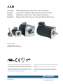 1
1
-
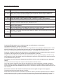 2
2
-
 3
3
-
 4
4
-
 5
5
-
 6
6
-
 7
7
-
 8
8
-
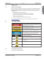 9
9
-
 10
10
-
 11
11
-
 12
12
-
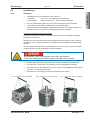 13
13
-
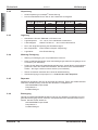 14
14
-
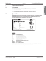 15
15
-
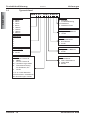 16
16
-
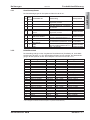 17
17
-
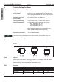 18
18
-
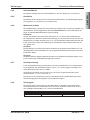 19
19
-
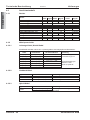 20
20
-
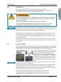 21
21
-
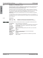 22
22
-
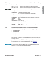 23
23
-
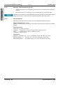 24
24
-
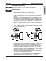 25
25
-
 26
26
-
 27
27
-
 28
28
-
 29
29
-
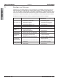 30
30
-
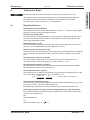 31
31
-
 32
32
-
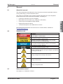 33
33
-
 34
34
-
 35
35
-
 36
36
-
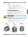 37
37
-
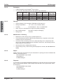 38
38
-
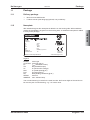 39
39
-
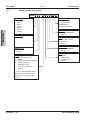 40
40
-
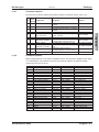 41
41
-
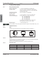 42
42
-
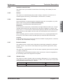 43
43
-
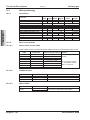 44
44
-
 45
45
-
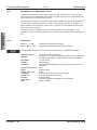 46
46
-
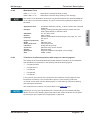 47
47
-
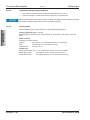 48
48
-
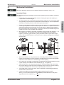 49
49
-
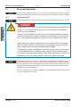 50
50
-
 51
51
-
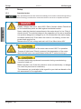 52
52
-
 53
53
-
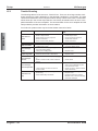 54
54
-
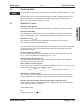 55
55
-
 56
56
-
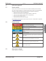 57
57
-
 58
58
-
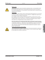 59
59
-
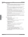 60
60
-
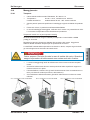 61
61
-
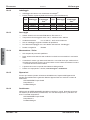 62
62
-
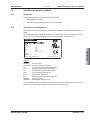 63
63
-
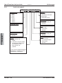 64
64
-
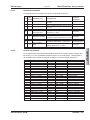 65
65
-
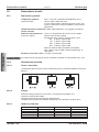 66
66
-
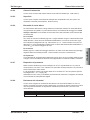 67
67
-
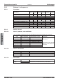 68
68
-
 69
69
-
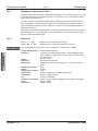 70
70
-
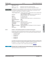 71
71
-
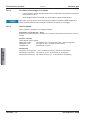 72
72
-
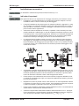 73
73
-
 74
74
-
 75
75
-
 76
76
-
 77
77
-
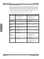 78
78
-
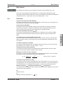 79
79
-
 80
80
-
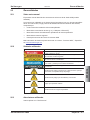 81
81
-
 82
82
-
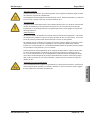 83
83
-
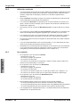 84
84
-
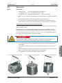 85
85
-
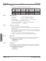 86
86
-
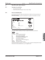 87
87
-
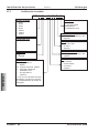 88
88
-
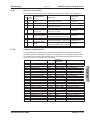 89
89
-
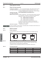 90
90
-
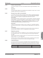 91
91
-
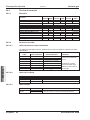 92
92
-
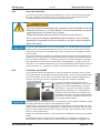 93
93
-
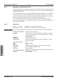 94
94
-
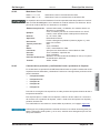 95
95
-
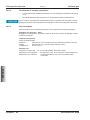 96
96
-
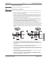 97
97
-
 98
98
-
 99
99
-
 100
100
-
 101
101
-
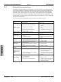 102
102
-
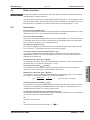 103
103
-
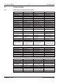 104
104
-
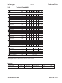 105
105
-
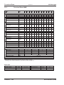 106
106
-
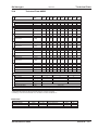 107
107
-
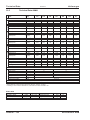 108
108
-
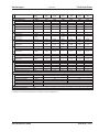 109
109
-
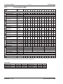 110
110
-
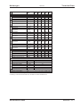 111
111
-
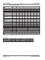 112
112
-
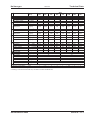 113
113
-
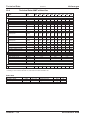 114
114
-
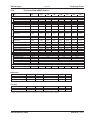 115
115
-
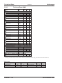 116
116
-
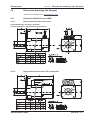 117
117
-
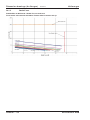 118
118
-
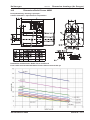 119
119
-
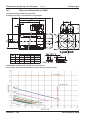 120
120
-
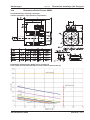 121
121
-
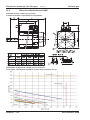 122
122
-
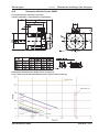 123
123
-
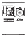 124
124
-
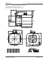 125
125
-
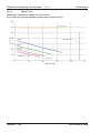 126
126
-
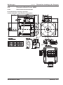 127
127
-
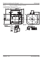 128
128
-
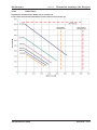 129
129
-
 130
130
-
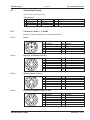 131
131
-
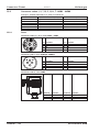 132
132
-
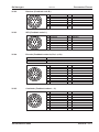 133
133
-
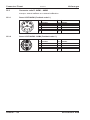 134
134
-
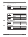 135
135
-
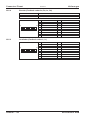 136
136
-
 137
137
-
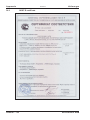 138
138
-
 139
139
-
 140
140


Kollmorgen AKM Series Manual de usuario
- Tipo
- Manual de usuario
En otros idiomas
- italiano: Kollmorgen AKM Series Manuale utente
- English: Kollmorgen AKM Series User manual
- Deutsch: Kollmorgen AKM Series Benutzerhandbuch
Documentos relacionados
Otros documentos
-
Plymovent SFD Manual de usuario
-
ABB M2A Series Installation, Operation & Maintenance Manual
-
 Rossi HC3 Instrucciones de operación
-
Eurotherm SSM1 / SSM2 El manual del propietario
-
Socomec FUSERBLOC Instrucciones de operación
-
Trane CAP 1802 Manual de usuario
-
 T&S BRASS B-1450-01 Guía de instalación
-
Behringer Ultracurve Pro DEQ2496 Guía de inicio rápido
-
JABSCO 52700 Guía de instalación
-
Behringer DCX2496 Guía de inicio rápido

