Varian TV 301 Navigator 969-8827 Manual de usuario
- Tipo
- Manual de usuario

TV 301
Navigator
Pump models:
969-8918 969-8919
969-8920 969-8921
Kit models:
969-8824 969-8825
969-8826 969-8827
969-8828 969-8829
969-8830 969-8831
Controller model:
969-8972 969-8973
MANUALE DI ISTRUZIONI
BEDIENUNGSHANDBUCH
NOTICE DE MODE D’EMPLOI
MANUAL DE INSTRUCCIONES
MANUAL DE INSTRUÇÕES
BEDRIJFSHANDLEIDING
INSTRUKSTIONSBOG
BRUKSANVISNING
INSTRUKSJON MANUAL
OHJEKÄSIKIRJA
ODHGIES CRHSEWS
INSTRUCTION MANUAL
87-900-946-01(B)
MARCH 2003

TV 301 Navigator


ISTRUZIONI PER L’USO..............................................................................................................................1
GEBRAUCHSANLEITUNG...........................................................................................................................3
MODE D’EMPLOI.........................................................................................................................................5
INSTRUCCIONES DE USO..........................................................................................................................7
INSTRUÇÕES PARA O USO .......................................................................................................................9
GEBRUIKSAANWIJZINGEN ......................................................................................................................11
BRUGSANVISNING ...................................................................................................................................13
BRUKSANVISNING....................................................................................................................................15
BRUKERVEILEDNING ...............................................................................................................................17
KÄYTTÖOHJEET.......................................................................................................................................19
PDHGIES CRHSEWS .....................................................................................................................................21
INSTRUCTIONS FOR USE ........................................................................................................................23
TECHNICAL INFORMATION......................................................................................................................25
DESCRIPTION OF THE TV 301 NAVIGATOR .......................................................................25
Pump Description..........................................................................................................25
Controller Description....................................................................................................26
TECHNICAL SPECIFICATION................................................................................................26
TV 301 NAVIGATOR OUTLINE ..............................................................................................27
INTERCONNECTIONS...........................................................................................................30
P3 - Vent.......................................................................................................................30
P4 – External fan ..........................................................................................................30
J5 - IN-OUT ..................................................................................................................30
P2 - Serial.....................................................................................................................33
INPUT POWER CONNECTION ON THE MODEL 969-8972...................................................33
RS 232/RS 485 COMMUNICATION DESCRIPTION...............................................................33
Communication Format.................................................................................................33
Communication Protocol ...............................................................................................33
Window Meanings.........................................................................................................35
INLET SCREEN INSTALLATION............................................................................................36
HEATER BAND INSTALLATION ............................................................................................37
AIR COOLING KIT INSTALLATION........................................................................................38
TV 301 with Navigator Controller...................................................................................38
WATER COOLING KIT INSTALLATION.................................................................................39
VENT ACCESSORIES............................................................................................................40
TV 301 Navigator Controller Compatible .......................................................................40
Standard Rack Controller Compatible ...........................................................................40
VIBRATION ISOLATOR INSTALLATION................................................................................41
PURGE VALVE INSTALLATION.............................................................................................41
SERIAL CABLE INSTALLATION ............................................................................................42
TV 301 CONTROLLER INSTALLATION .................................................................................42
TYPICAL LAYOUT DIAGRAM ................................................................................................43
With Navigator Controller..............................................................................................43
With Standard Rack Controller......................................................................................44
Connection A - HIGH VACUUM FLANGE .....................................................................44
Connection configurations .............................................................................................45
Connection B - FORE-VACUUM PUMP ........................................................................45
Connection C - ELECTRICAL........................................................................................45
PUMP USED WITH CORROSIVE GASES .............................................................................46
PUMP USED IN PRESENCE OF MAGNETIC FIELDS ...........................................................47
ACCESSORIES AND SPARE PARTS ....................................................................................47

ISTRUZIONI PER L'USO
1 87-900-946-01(B)
INFORMAZIONI GENERALI
Questa apparecchiatura è destinata ad uso professionale. L'utilizzatore
deve leggere attentamente il presente manuale di istruzioni ed ogni altra
informazione addizionale fornita dalla Varian prima dell'utilizzo dell'ap-
parecchiatura. La Varian si ritiene sollevata da eventuali responsabilità
dovute all'inosservanza totale o parziale delle istruzioni, ad uso impro-
prio da parte di personale non addestrato, ad interventi non autorizzati o
ad uso contrario alle normative nazionali specifiche.
Il TV 301 Navigator è un sistema integrato costituito da una pom-
pa turbomolecolare per applicazioni di alto e ultra alto vuoto e dal
relativo controller. Il sistema è capace di pompare qualsiasi tipo di
gas o di composto gassoso, ma non è adatto per il pompaggio di
liquidi o di particelle solide.
L'effetto pompante è ottenuto tramite una turbina rotante ad eleva-
ta velocità (56000 giri/min. max) mossa da un motore elettrico tri-
fase ad alto rendimento. Il TV 301 Navigator è totalmente privo di
agenti contaminanti, ed è quindi adatto per applicazioni che richie-
dono un vuoto "pulito".
Ha inoltre dei connettori ausiliari tramite i quali è possibile alimen-
tare un ventilatore aggiuntivo, comandare la valvola di vent, pilotar-
lo da remoto tramite un computer host collegato con linea seriale
(RS232 o RS485).
Nei paragrafi seguenti sono riportate tutte le informazioni necessa-
rie a garantire la sicurezza dell'operatore durante l'utilizzo dell'ap-
parecchiatura. Informazioni dettagliate sono fornite nell'appendice
“Technical information”.
Questo manuale utilizza le seguenti convenzioni:
!
PERICOLO!
I messaggi di pericolo attirano l'attenzione dell'operatore su una
procedura o una pratica specifica che, se non eseguita in modo
corretto, potrebbe provocare gravi lesioni personali.
!
ATTENZIONE!
I messaggi di attenzione sono visualizzati prima di procedure che,
se non osservate, potrebbero causare danni all'apparec-chiatura.
NOTA
Le note contengono informazioni importanti estrapolate dal testo.
IMMAGAZZINAMENTO
Per garantire il massimo livello di funzionalità ed affidabilità delle pompe
Turbomolecolari Varian, devono essere osservate le seguenti prescri-
zioni:
• durante il trasporto, lo spostamento e l'immagazzinamento
delle pompe non devono essere superate le seguenti condi-
zioni ambientali:
• temperatura: da –20 °C a 70 °C
• umidità relativa: da 0 a 95% (non condensante)
• il cliente deve sempre avviare le pompe turbomolecolari nel
modo Soft-Start quando ricevute e messe in funzione per la
prima volta
• il tempo di immagazzinamento di una pompa turbomolecolare
è di 10 mesi dalla data di spedizione.
!
ATTENZIONE!
Se, per qualsiasi ragione, il tempo di immagazzinamento è supe-
riore, occorre reinviare la pompa in fabbrica. Per ogni informazio-
ne, si prega di contattare il locale rappresentante della Varian.
PREPARAZIONE PER L'INSTALLAZIONE
Il TV 301 Navigator viene fornito in un imballo protettivo speciale;
se si presentano segni di danni, che potrebbero essersi verificati
durante il trasporto, contattare l'ufficio vendite locale.
Durante l'operazione di disimballaggio, prestare particolare atten-
zione a non lasciar cadere il TV 301 Navigator e a non sottoporlo
ad urti o vibrazioni. Non disperdere l'imballo nell'ambiente.
Il materiale è completamente riciclabile e risponde alla direttiva
CEE 85/399 per la tutela dell'ambiente.
!
ATTENZIONE!
Onde evitare problemi di degasamento, non toccare con le mani
nude i componenti destinati ad essere esposti al vuoto. Utilizzare
sempre i guanti o altra protezione adeguata.
NOTA
Il TV 301 Navigator non può essere danneggiato rimanendo
semplicemente esposto all'atmosfera. Si consiglia comunque di
mantenere chiusa la pompa fino al momento dell'installazione sul
sistema onde evitare eventuale inquinamento da polvere.
INSTALLAZIONE
Non installare e/o utilizzare la pompa in ambienti esposti ad agenti
atmosferici (pioggia, gelo, neve), polveri, gas aggressivi, in am-
bienti esplosivi o con elevato rischio di incendio.
Durante il funzionamento è necessario che siano rispettate le se-
guenti condizioni ambientali:
− pressione massima: 2 bar oltre la pressione atmosferica
− temperatura: da + 5 °C a +35 °C (vedere grafico
nell’appendice “Technical Information”)
− umidità relativa: 0 - 95% (non condensante).
In presenza di campi elettromagnetici la pompa deve essere pro-
tetta tramite opportuni schermi. Vedere l'appendice "Technical
Information" per ulteriori dettagli.
!
ATTENZIONE!
Staccare l’adesivo e togliere il tappo di protezione solo al mo-
mento del collegamento della turbopompa al sistema.

ISTRUZIONI PER L'USO
2 87-900-946-01(B)
Il TV 301 Navigator deve essere collegato ad una pompa primaria (ve-
dere schema in "Technical Information").
Il TV 301 Navigator può essere installato in qualsiasi posizione. Fissare
il TV 301 Navigator in posizione stabile collegando la flangia di ingresso
della turbopompa ad una controflangia fissa capace di resistere ad una
coppia di 1000 Nm attorno al proprio asse.
La turbopompa con flangia di ingresso ISO deve essere fissata
alla camera da vuoto per mezzo di morsetti doppi o morsetti singo-
li. La seguente tabella descrive, per ogni dimensione flangia e tipo
di morsetto, il numero di morsetti necessari e con quale coppia di
serraggio stringerli.
FLANGIA TIPO DI
MORSETTO
N. COPPIA DI SER-
RAGGIO
ISO 100 Morsetto doppio
con filettatura M10
4 22 Nm
Morsetto singolo
con filettatura M8
8 11 Nm
ISO 160 Morsetto doppio
con filettatura M10
4 22 Nm
Morsetto singolo
con filettatura M10
8 22 Nm
La turbopompa con flangia di ingresso ConFlat deve essere fissata alla
camera da vuoto per mezzo dell'apposita minuteria meccanica Varian.
Per ulteriori dettagli vedere l'appendice "Technical Information".
NOTA
Il TV 301 Navigator non può essere fissato tramite la sua base.
!
ATTENZIONE!
Il TV 301 Navigator appartiene alla seconda categoria di installa-
zione (o sovratensione) prevista dalla normativa EN 61010-1.
Connettere quindi il dispositivo ad una linea di alimentazione che
soddisfi tale categoria.
Il TV 301 Navigator ha dei connettori per gli ingressi/uscite e per
la comunicazione seriale che devono essere connessi ai circuiti
esterni in modo che nessuna parte sotto tensione sia accessibile.
Assicurarsi che l’isolamento del dispositivo connesso al TV 301
Navigator abbia un isolamento adeguato anche in condizione di
guasto singolo come previsto dalla normativa EN 61010-1.
Per l'installazione degli accessori opzionali, vedere "Technical Informa-
tion".
USO
In questo paragrafo sono riportate le principali procedure operative.
Prima di usare il sistema effettuare tutti i collegamenti elettrici e
pneumatici. Durante l'eventuale riscaldamento della camera da
vuoto, la temperatura sulla flangia di ingresso non deve essere
superiore a 120 °C.
!
PERICOLO!
Non far funzionare mai la pompa se la flangia di ingresso non è
collegata alla camera a vuoto o non è chiusa con la flangia di chiusura.
Non toccare la turbopompa e i suoi eventuali accessori durante le ope-
razioni di riscaldamento. L'elevata temperatura può causare lesioni alle
persone.
!
ATTENZIONE!
Evitare urti, oscillazioni o bruschi spostamenti della turbopompa quan-
do è in funzione. I cuscinetti potrebbero danneggiarsi.
Per la mandata all'aria della pompa utilizzare aria o gas inerte e-
sente da polvere o particelle. La pressione di ingresso attraverso
l'apposita porta deve essere inferiore a 2 bar (oltre la pressione
atmosferica).
Per il pompaggio di gas aggressivi queste pompe sono dotate di una
apposita porta attraverso la quale è necessario fornire alla pompa un
flusso di gas inerte (Azoto o Argon) per proteggere i cuscinetti (vedere
l'appendice "Technical Information").
!
PERICOLO!
Quando la pompa viene utilizzata per il pompaggio di gas tossici,
infiammabili o radioattivi, seguire le appropriate procedure tipiche
di ciascun gas.
Non usare la pompa in presenza di gas esplosivi.
Accensione ed Uso del TV 301 Navigator
Per accendere il TV 301 Navigator è sufficiente fornire la tensione di
alimentazione. Il controller incorporato riconosce automaticamente la
presenza dei segnali di interlock e di avvio ed avvia la pompa.
La prima partenza della pompa avviene nel modo “Soft Start” che,
al termine del ciclo di avvio, si disabilita automaticamente, per cui
tutti i successivi avvii della pompa avvengono senza il modo “Soft
Start”. Per riavere una partenza con “Soft Start” attivo occorre ria-
bilitare il modo suddetto tramite software (vedere il paragrafo “RS
232/485 COMMUNICATION DESCRIPTION” nell’appendice
“Technical Information”).
Il LED verde posto sul pannello della base del TV 301 Navigator
indica, con la frequenza del suo lampeggio, le condizioni operative
del sistema:
− acceso fisso: la pompa è in rotazione normale;
− lampeggiante lentamente (periodo di circa 400 ms): il sistema
è in stato di rampa, o di frenata, o di Stop, o di “W aiting for in-
terlock”;
− lampeggiante velocemente (periodo di circa 200 ms): condi-
zione di errore.
Arresto del TV 301 Navigator
Per arrestare il TV 301 Navigator è sufficiente togliere la tensione
di alimentazione. Il controller incorporato arresta immediatamente
la pompa.
Arresto di Emergenza
Per arrestare in condizioni di emergenza il TV 301 Navigator oc-
corre staccare il cavo di alimentazione dal controller.
MANUTENZIONE
Il TV 301 Navigator non richiede alcuna manutenzione. Qualsiasi inter-
vento deve essere eseguito da personale autorizzato.
!
PERICOLO!
Prima di effettuare qualsiasi intervento sul sistema scollegarlo
dall’alimentazione, mandare all'aria la pompa aprendo l'apposita
valvola, attendere fino al completo arresto del rotore ed attendere
che la temperatura superficiale della pompa sia inferiore a 50°C.
In caso di guasto è possibile usufruire del servizio di riparazione
Varian o del "Varian advanced exchange service", che permette di
ottenere un sistema rigenerato in sostituzione di quello guasto.
NOTA
Prima di rispedire al costruttore un sistema per riparazioni o a-
dvanced exchange service, è indispensabile compilare e far per-
venire al locale ufficio vendite la scheda "Sicurezza e Salute"
allegata al presente manuale di istruzioni. Copia della stessa de-
ve essere inserita nell'imballo del sistema prima della spedizione.
Qualora un sistema dovesse essere rottamato, procedere alla sua
eliminazione nel rispetto delle normative nazionali specifiche.

GEBRAUCHSANLEITUNG
3 87-900-946-01(B)
ALLGEMEINE INFORMATIONEN
Dieser Apparat ist für den fachmännischen Gebrauch bestimmt. Vor
dem Gebrauch hat der Benutzer dieses Handbuch sowie alle weiteren
mitgelieferten Zusatzdokumentationen genau zu lesen. Bei auch teil-
weiser Nichtbeachtung der enthaltenen Anweisungen, unsachgemä-
ßem Gebrauch durch ungeschultes Personal, nicht autorisierten Ein-
griffen und Mißachtung der nationalen einschlägigen Normen über-
nimmt die Firma Varian keinerlei Haftung.
Modell TV 301 Navigator ist ein integriertes System, das aus einer
Turbomolekularpumpe für Hoch- und Höchstvakuum-
anwendungen, integriert mit einem entsprechenden Controller,
besteht. Das System eignet sich für die Förderung aller Arten von
Gasen oder gashaltigen Gemischen, nicht jedoch für die Förde-
rung von Flüssigstoffen oder Festpartikeln. Die Pumpwirkung wird
durch eine hochtourige Turbine (max. 56000 1/min) erreicht, die
von einem Hochleistungs-drehstrommotor angetrieben wird. Mo-
dell TV 301 Navigator enthält keinerlei umweltschädliche Sub-
stanzen und eignet sich deshalb auch für Anwendungen, die ein
"sauberes" Vakuum erfordern. Modell TV 301 Navigator verfügt
des weiteren über Zusatzanschlüsse, über die ein zusätzlicher
Ventilator versorgt, das Entlüftungsventil gesteuert oder die Vor-
richtung von einem Host Computer über eine serielle Leitung
gesteuert werden kann (RS232, RS485).
In den folgenden Abschnitten sind alle erforderlichen Informatio-
nen für die Sicherheit des Bedieners bei der Anwendung des
Geräts aufgeführt. Detaillierte technische Informationen sind im
Anhang "Technical Information" enthalten.
In dieser Gebrauchsanleitung werden Sicherheitshinweise
folgendermaßen hervorgehoben:
!
GEFAHR!
Die Gefahrenhinweise lenken die Aufmerksamkeit des Bedieners
auf einen Vorgang oder eine bestimmte Ausführungsweise, die
bei unkorrekter Ausführung schwere Verletzungen hervorrufen
könnten.
!
ACHTUNG!
Die Warnhinweise werden vor Vorgängen angegeben, die bei
Nichtbeachtung Schäden an der Anlage verursachen könnten.
HINWEIS
Die Hinweise enthalten wichtige Informationen, die aus dem Text
hervorgehoben werden.
LAGERUNG
Um ein Höchstmaß an Effizienz und Zuverlässigkeit der Varian Tur-
bomolekularpumpen zu gewährleisten, sind die folgenden Anweisun-
gen zu beachten:
• Während des Transports, der Handhabung und der Einlage-
rung der Pumpen dürfen die folgenden Grenzwerte nicht ü-
berschritten werden:
• Temperatur: von –20 °C bis 70 °C
• Relative Feuchtigkeit: von 0 bis 95% (nicht kondensierend)
• Der Kunde hat die Turbomolekularpumpen nach dem Emp-
fang bei Erstinbetriebnahme stets im Modus Soft-Start in-
gangzusetzen.
• Die Lagerdauer für eine Turbomolekularpumpe beträgt 10
Monate ab dem Speditionsdatum.
!
ACHTUNG!
Falls die Lagerdauer aus verschiedentlichen Gründen die genann-
te Frist überschreiten sollte, ist die Pumpe an das Werk zurück-
zusenden. Für Informationen wenden Sie sich bitte an den örtli-
chen Varian Vertreter.
VOR DER INSTALLATION
Modell TV 301 Navigator wird in einer speziellen Schutzverpa-
ckung geliefert. Eventuelle Transportschäden sind der zuständi-
gen örtlichen Verkaufsstelle zu melden. Modell TV 301 Navigator
ist vorsichtig auszupacken, wobei es vor dem Herunterfallen und
vor Stößen und Vibrationen zu schützen ist. Das Verpackungsma-
terial ist vorschriftsgemäß zu entsorgen. Es ist vollständig recyc-
lebar und entspricht der Richtlinie 85/399/EWG für Umwelt-
schutz.
!
ACHTUNG!
Um Entgasungen zu vermeiden, dürfen die Teile, die mit dem
Vakuum in Berührung kommen, nicht mit den bloßen Händen
angefaßt werden. Es sind stets Schutzhandschuhe oder andere
Schutzmittel zu verwenden.
HINWEIS
Modell TV 301 Navigator kann durch die Umgebung an sich kei-
ne Schäden erleiden. Es sollte jedoch bis zur Installation an der
Anlage geschlossen bleiben, um Verunreinigungen durch Staub
zu vermeiden.
INSTALLATION
Die Pumpe darf nicht in Umgebungen, die ungeschützt vor Wetter
(Regen, Frost, Schnee), Staub und aggressiven Gasen sind,
sowie auch nicht in explosionsfähigen oder erhöht brandgefährde-
ten Umgebungen installiert und/oder benutzt werden.
Beim Betrieb müssen folgende Umgebungsbedingungen eingehalten
werden:
- Maximaler Druck: 2 bar über dem atmosphärischen Druck
- Temperatur: von +5°C bis +35°C (siehe Diagramm im An-
hang "Technical Information")
- Relative Luftfeuchtigkeit: 0 - 95% (nicht kondensierend).
Bei Vorhandensein von elektromagnetischen Feldern ist die Pumpe
entsprechend abzuschirmen. Für ausführliche Informationen siehe im
Anhang "Technical Information".
!
ACHTUNG!
Das Klebeband abziehen und den Schutzdeckel erst bei
Anschluß der Turbopumpe an das System abnehmen.

GEBRAUCHSANLEITUNG
4 87-900-946-01(B)
Modell TV 301 Navigator ist an eine Primärpumpe anzuschließen
(siehe Schema in "Technical Information").
Modell TV 301 Navigator kann in jeder beliebigen Position installiert
werden. Modell TV 301 Navigator ist stabil zu befestigen, indem der
Flansch am Eingang der Turbopumpe an einen festen Gegenflansch
angeschlossen wird, der mit einem Drehmoment von 1000 Nm um
seine eigene Achse belastbar ist. Turbopumpen mit einem
ISO-Eingangsflansch sind mittels doppelter oder einfacher Klemm-
schellen an die Vakuumkammer anzuschließen. In der nachstehenden
Tabelle sind die Anzahl der Klemmschellen und das Anzugsmoment
für die jeweiligen Flanschgrößen und Schellenarten angegeben.
FLANSCH
KLEMMSCHELLE
ANZ. ANZUGSMOMENT
ISO 100 Doppelschelle mit
Gewinde M10
4 22 Nm
Einzelschelle mit
Gewinde M8
8 11 Nm
ISO 160 Doppelschelle mit
Gewinde M10
4 22 Nm
Einzelschelle mit
Gewinde M10
8 22 Nm
Turbopumpen mit ConFlat-Eingangsflansch sind mit dem speziel-
len Varian-Befestigungsmaterial an die Vakuum kammer anzu-
schließen. Für ausführliche Informationen siehe im Anhang
"Technical Information".
HINWEIS
Modell TV 301 Navigator kann nicht mittels seines Sockels befes-
tigt werden.
!
ACHTUNG!
Der TV 301 Navigator gehört zur zweiten Installationsklasse (Ü-
berdruck) die von den Normen EN 61010-1 vorgesehen ist. Die
Vorrichtung muß daher an eine Speisungsleitung angeschlossen
werden, die dieser Kategorie entspricht.
Der TV 301 Navigator hat Verbinder für den Ein-und Ausgang
und die Schnittstellenkommunikation, die an die Außenkreise
angeschlossen werden müssen, sodaß kein Teil unter Spannung
zugänglich ist . Sicherstellen, daß die Isolierung der an den TV
301 Navigator angeschlossenen Vorrichtung auch bei einer Ein-
zelstörung ausreichend isoliert, wie es von der Richtlinie EN
61010-1 vorgesehen wird.
Für die Installation der Optionsteile siehe im Anhang "Technical
Information".
GEBRAUCH
In diesem Abschnitt werden die wichtigsten Betriebsvorgänge
erläutert. Vor Benutzung des Systems sind alle elektrischen und
pneumatischen Anschlüsse auszuführen. Während der eventuel-
len Aufheizung der Vakuumkammer darf die Temperatur am Ein-
gangsflansch 120°C nicht überschreiten.
!
GEFAHR!
Die Pumpe darf nicht in Betrieb genommen werden, wenn der
Eingangsflansch nicht an die Vakuumkammer angeschlossen
oder nicht mit dem Verschlußflansch verschlossen ist.
Während des Aufheizens dürfen weder die Pumpe noch eventuel-
le heiße Zubehörteile berührt werden. Es besteht Verbrennungs-
gefahr.
!
ACHTUNG!
Während des Betriebs sind Stoß- und Vibrationseinwirkungen sowie
Ruckbewegungen an der Turbopumpe zu vermeiden, da die Lager
beschädigt werden könnten.
Für die Belüftung der Pumpe trockene staub- und partikelfreie Luft
oder Inertgase verwenden. Der Eingangsdruck am Belüftung-
sanschluß soll unter 2 bar (über dem atmosphärischen Druck) betra-
gen.
Zum Pumpen von aggressiven Gasen sind die Pumpen mit einer
Öffnungsklappe ausgestattet, über die zum Schutz der Lager Inertgas
(Stickstoff oder Argon) zuzuleiten ist (siehe Anhang "Technical Infor-
mation").
!
GEFAHR!
Wenn die Pumpe zur Förderung von giftigen, leicht entflammbaren
oder radioaktiven Gasen benutzt wird, sind die für das jeweilige Gas
vorgeschriebenen Vorgänge und Maßnahmen zu befolgen.
Die Pumpe darf niemals bei Vorhandensein von explosionsfähigen
Gasen verwendet werden.
Einschaltung und Gebrauch von Modell TV 301
Navigator
Zur Einschaltung von Modell TV 301 ist es mit der erforderlichen
Versorgungsspannung zu versorgen. Der eingebaute Controller
erfaßt automatisch das Vorhandensein von Interlock- und Anlauf-
signalen und startet die Pumpe.
Die Erstinbetriebnahme der Pumpe erfolgt im Modus "Soft Start",
der sich nach dem Anlaufzyklus selbsttätig abschaltet. Daher
erfolgen alle nachfolgenden Pumpenanläufe ohne den Modus
"Soft Start". Um die Pumpe erneut im Modus "Soft Start" zu star-
ten, ist dieser Modus mittels der Software wieder freizugeben
(siehe Abschnitt "RS 232 COMMUNICATION DESCRIPTION"
im Anhang "Technical Information").
Die grüne LED LD1 an der Bodenplatte von Modell TV 301 gibt mit der
Häufigkeit ihres Blinkens die Betriebsbedingungen des System an:
- Daueranzeige: Die Pumpe befindet sich im normalen Betrieb.
- Langsame Blinkanzeige (ca. 400 ms): das System befindet
sich entweder im Status Rampe, Abbremsung, Stopp oder
“Waiting for Interlock”.
- Schnelle Blinkanzeige (ca. 200 ms): Fehlerstatus.
Stoppen von Modell TV 301 Navigator
Zum Stoppen von Modell TV 301 Navigator ist die Versorgungs-
spannung abzuschalten. Der eingebaute Controller sorgt für den
sofortigen Pumpenstopp.
Not-Aus
Zur Stillsetzung von Mod. TV 301 Navigator in Notsituationen ist
vom Controller das Netzkabel abzuziehen.
WARTUNG
Modell TV 301 Navigator erfordert keine Wartung. Eventuelle Eingriffe
dürfen nur von autorisiertem Fachpersonal ausgeführt werden.
!
GEFAHR!
Vor jedem Eingriff am System den Netzstecker ziehen, die Pumpe
über Öffnung des entsprechenden Ventils belüften und abwarten,
bis der Rotor vollkommen stillsteht und die Temperatur am Pum-
pengehäuse unter 50°C abgesunken ist.
Bei Defekten kann der Varian Service oder der "Varian advanced
exchange service" in Anspruch genommen werden, der ein gene-
ralüberholtes System als Ersatz für das defekte System zur Ver-
fügung stellt.
HINWEIS
Bevor Fa. Varian ein System zur Reparatur oder den Umtausch-
dienst eingesandt wird, ist das Formular "Sicherheit und Gesund-
heit", das diesem Handbuch beiliegt, ausgefüllt an die örtliche
Verkaufsstelle zu senden. Eine Kopie ist der Verpackung des
Systems vor dem Versand beizulegen.
Eine eventuelle Verschrottung hat unter Beachtung der einschlä-
gigen nationalen Vorschriften zu erfolgen.

MODE D’EMPLOI
5 87-900-946-01(B)
INDICATIONS GENERALES
Cet appareillage a été conçu en vue d'une utilisation profession-
nelle. Avant toute utilisation de l'appareil, il est conseillé à l'utilisa-
teur de lire attentivement cette notice d'instructions ainsi que toute
autre indication supplémentaire fournie par Varian qui décline par
conséquent toute responsabilité en cas de non respect total ou
partiel des instructions données, d'utilisation impropre par un
personnel non formé, d'opérations non autorisées ou d'emploi
contraire aux réglementations nationales spécifiques. Le TV 301
Navigator est un système intégré, constitué d'une pompe turbo-
moléculaire conçue pour des applications de vide poussé et ultra-
poussé et doté d'un contrôleur. Le système est à même de pom-
per tous les types de gaz et de composés gazeux mais il n'est pas
adapté au pompage de liquides ou de particules solides. L'effet de
pompage est obtenu grâce à une turbine tournant à vitesse élevée
(56000 tr/min maxi), mue par un moteur électrique triphasé à haut
rendement. Le TV 301 Navigator est totalement exempt d'agents
polluants et il est par conséquent indiqué pour toutes les applica-
tions exigeant un vide "propre". Le TV 301 Navigator est en outre
doté de connecteurs auxiliaires permettant d'alimenter un ventila-
teur supplémentaire, de commander la soupape de ventilation, de
le piloter à distance à l'aide d'un ordinateur host connecté par
ligne sérielle.Les paragraphes suivants fournissent toutes les
indications nécessaires à garantir la sécurité de l'opérateur pen-
dant l'utilisation de l'appareillage. Des renseignements plus détail-
lés se trouvent dans l'appendice "Technical Information".
Cette notice utilise les signes conventionnels suivants:
!
DANGER!
Les messages de danger attirent l'attention de l'opérateur sur une
procédure ou une manoeuvre spéciale qui, effectuée de façon
impropre, risque de provoquer de graves lésions
!
ATTENTION!
Les messages d'attention apparaissent avant certaines procédu-
res dont le non respect pourrait endommager sérieusement l'ap-
pareillage.
NOTE
Les notes contiennent des renseignements importants, extrapo-
lés du texte.
STOCKAGE
Pour garantir les performances et la fiabilité maximales des pom-
pes turbomoléculaires Varian, il est indispensable de respecter les
instructions suivantes :
• Le transport, la manutention et le stockage des pompes, doi-
vent impérativement avoir lieu dans les conditions ambiantes
suivantes:
• température : de –20 °C à +70 °C
• humidité relative : de 0 à 95% (non condensante)
• A la première utilisation, les pompes turbomoléculaires doi-
vent toujours être mises en marche en mode soft-Start.
• Le temps de stockage d'une pompe turbomoléculaire est de
10 mois à compter de la date d'expédition.
!
ATTENTION!
En cas de dépassement du temps de stockage, la pompe doit être
retournée en usine. Pour tout renseignement, contacter le repré-
sentant Varian de zone.
PREPARATION POUR L'INSTALLATION
Le TV 301 Navigator est livré dans un emballage de protection spécial;
en cas d'endommagement de l'emballage pouvant s'être produit pen-
dant le transport, contacter le bureau de vente local.
Pendant l'opération d'ouverture de l'emballage, veiller tout particu-
lièrement à ne pas laisser tomber le TV 301 Navigator et à ne lui
faire subir aucun choc et aucune vibration.
Ne pas abandonner l'emballage dans la nature. Le matériel est
entièrement recyclable et conforme à la directive CEE 85/399 en
matière de protection de l'environnement.
!
ATTENTION!
Afin d'éviter tout problème de dégazage, ne pas toucher, à mains
nues, les éléments devant être exposés au vide. Mettre toujours
des gants ou toute autre protection appropriée.
NOTE
Le TV 301 ne peut s'endommager en restant simplement exposé
à l'atmosphère. Toutefois, afin d'éviter toute pollution due à la
poussière, il est conseillé de le garder dans son emballage clos
jusqu'au moment de l'installation.
INSTALLATION
Ne pas installer et/ou utiliser la pompe dans des milieux exposés
aux agents atmosphériques (pluie, gel, neige), à la poussière, aux
gaz agressifs ainsi que dans des milieux explosifs ou à fort risque
d'incendie.
Pendant le fonctionnement, il est nécessaire de respecter les
conditions environnementales suivantes:
- pression maxi: 2 bar au-delà de la pression atmosphérique
- température: de +5°C° à +35°C (Cf. graphique dans "Techni-
cal Information")
- humidité relative: 0 - 95% (non condensante)
En présence de champs magnétiques, la pompe doit être proté-
gée à l'aide d'écrans appropriés. Pour tout autre renseignement,
se reporter à l'opuscule "Technical Information". Le TV 301 Navi-
gator doit être connecté à une pompe primaire (Cf. schéma dans
"Technical Information").
!
ATTENTION!
Ne décoller l'adhésif et ne retirer le couvercle de protection qu'au
moment de brancher la turbopompe au système.

MODE D’EMPLOI
6 87-900-946-01(B)
Le TV 301 Navigator peut être installée dans n'importe quelle
position. Le fixer dans une position stable, en reliant la bride d'en-
trée de la turbopompe à une contre-bride fixe pouvant supporter
un couple de serrage de 1000 Nm autour de son axe. La turbo-
pompe à bride d'entrée ISO doit être fixée à la chambre à vide à
l'aide de colliers doubles ou simples. Le tableau suivant décrit,
pour chaque dimension de bride et pour chaque type de collier, le
nombre de colliers nécessaires ainsi que le couple de serrage
prescrit.
BRIDE TYPE DE
COLLIER
N. COUPLE DE
SERRAGE
ISO 100 Collier double
à filet M10
4 22 Nm
Collier simple
à filet M8
8 11 Nm
ISO 160 Collier double
à filet M10
4 22 Nm
Collier simple
à filet M10
8 22 Nm
La turbopompe à bride d'entrée ConFlat doit être fixée à la cham-
bre à vide à l'aide des éléments mécaniques Varian prévus à cet
effet. Pour tout autre détail, se reporter à l'appendice "Technical
Information".
NOTE
Le TV 301 Navigator ne peut être fixé par sa base.
!
ATTENTION!
Le TV 301 Navigator appartient à la deuxième catégorie d'installa-
tions (ou surtension) prévue par la norme EN 61010-1. De ce fait,
brancher le dispositif à une ligne d'alimentation compatible avec
cette catégorie.
Le TV 301 Navigator dispose de connecteurs pour les en-
trées/sorties et pour la communication en série qui doivent être
branchés aux circuits extérieurs de façon qu'aucune partie sous
tension ne soit accessible.
S'assurer que l'isolation du dispositif branché au TV 301 Naviga-
tor a une isolation appropriée même en condition de panne indivi-
duelle selon les termes de la norme EN 61010-1.
Pour l'installation des accessoires en option, se reporter à "Tech-
nical Information".
UTILIZATION
Ce paragraphe présente les principales procédures opérationnelles.
Avant d'utiliser le système, effectuer tous les branchements élec-
triques et pneumatiques. Pendant le chauffage éventuel de la
chambre à vide, la température de la bride d'entrée ne doit pas
dépasser 120°C.
!
DANGER!
Ne jamais faire fonctionner la pompe si la bride d'entrée n'est pas
reliée à la chambre à vide ou si elle n'est pas fermée avec la bride
de fermeture.
Eviter de toucher la turbopompe ainsi que ses accessoires éven-
tuels pendant les opérations de chauffage. La température élevée
peut être à l'origine de lésions graves.
!
ATTENTION!
Lorsque la turbopompe fonctionne, éviter tout choc, oscillation ou dé-
placement brusque car les paliers pourraient se détériorer.
Pour le refoulement de l'air de la pompe, utiliser de l'air ou du gaz
inerte exempt de poussière ou de particules. La pression d'entrée
à travers la porte prévue à cet effet doit être inférieure à 2 bar (au-
delà de la pression atmosphérique).
Pour le pompage de gaz agressifs, ces pompes sont dotées d'une
porte spéciale à travers laquelle il est nécessaire de fournir à la
pompe un flux de gaz inerte (azote ou argon) pour protéger les
paliers (voir l'appendice "Technical Information").
!
DANGER!
Lorsque la pompe est utilisée pour le pompage de gaz toxiques,
inflammables ou radioactifs, suivre les procédures typiques de
chaque gaz.
Ne pas utiliser la pompe en présence de gaz explosifs.
Mise en marche et utilisation du TV 301 Navigator
Pour allumer le TV 301 Navigator il suffit de fournir la tension d'alimen-
tation. Le contrôleur incorporé reconnaît automatiquement la présence
de signaux d'interlock et de démarrage et il actionne la pompe.
La première mise en marche de la pompe se fait en mode "Soft Start".
Au terme du cycle de démarrage, ce mode se désactive automatique-
ment et les mises en marche suivantes se font sans le passage "Soft
Start". Pour obtenir à nouveau une mise en marche "Soft Start", il faut
réactiver ce mode opératoire à l'aide du logiciel (Cf. paragraphe
"RS232 COMMUNICATION DESCRIPTION" dans l'appendice
"Technical Information").
La LED verte LD1 placée sur le panneau de la base du TV 301
indique, par sa fréquence de clignotement, les conditions opéra-
tionnelles du système:
- allumée fixe: la pompe est en rotation normale;
- clignote lentement (période d'environ 400 ms): le système est en
état de rampe, de freinage, de stop ou d’attente interlock.
- clignote rapidement (pédiode d'environ 200 ms): condition d'erreur.
Arrêt du TV 301 Navigator
Pour arrêter le TV 301 Navigator, il suffit de retirer la tension
d'alimentation. Le contrôleur incorporé arrête immédiatement la
pompe.
Arrêt d'urgence
Pour arrêter le TV 301 Navigator en conditions d'urgence, il faut
débrancher le cordon d'alimentation du contrôleur.
ENTRETIEN
Le TV 301 Navigator n'exige aucun entretien particulier. Toute
intervention doit être effectuée par un personnel agréé.
!
DANGER!
Avant toute intervention sur le système, le débrancher, refouler
l'air de la pompe en ouvrant la soupape prévue à cet effet, atten-
dre jusqu'à l'arrêt complet du rotor et jusqu'à ce que la tempéra-
ture superficielle de la pompe soit inférieure à 50°C.
En cas de panne, il est possible de bénéficier du service répara-
tions Varian ou du "Varian advanced exchange service" qui per-
met d'obtenir un système régénéré en remplacement du système
endommagé.
NOTE
Avant de renvoyer une pompe au constructeur pour réparation
ou "advanced exchange service", remplir et faire parvenir au
bureau Varian de votre région la fiche "Sécurité et Santé" jointe
au présent manuel d'instructions. Une copie de cette fiche devra
être mise dans l'emballage de la pompe avant l'expédition.
En cas de mise au rebut de la pompe, procéder à son élimination
conformément aux réglementations nationales concernant la ges-
tion des déchets.

INSTRUCCIONES DE USO
7 87-900-946-01(B)
INFORMACIÓN GENERAL
Este equipo es para uso profesional. El usuario ha de leer atentamente
el presente manual de instrucciones y cualquier otra información
suplementaria facilitada por Varian antes de usar el aparato. Varian se
considera libre de posibles responsabilidades debidas al
incumplimiento total o parcial de las instrucciones, al uso impropio por
parte de personal no preparado, a operaciones no autorizadas o a un
uso contrario a las normas nacionales específicas.
El TV 301 Navigator es un sistema integrado compuesto por una
bomba turbomolecular para aplicaciones de alto y ultra alto vacío
integrada por el controler correspondiente. El sistema puede bombear
cualquier tipo de gas o de composición gaseosa, pero no es adecuado
para bombear líquidos o partículas sólidas.
El efecto de bombeo se obtiene mediante una turbina rotativa de alta
velocidad (56000 r.p.m. máx.) movida por un motor eléctrico trifásico de
alto rendimiento. El TV 301 Navigator no posee ningún agente
contaminante y por lo tanto es adecuado para aplicaciones que
requieren un vacío’ “limpio”.
Asimismo, el TV 301 Navigator posee conectores auxiliares con los
que se puede alimentar un ventilador adicional, accionar la válvula de
ventilación, pilotarla a distancia con un ordenador host conectado
mediante línea serial (RS 232/RS 485).
A continuación se facilita toda la información necesaria para garantizar
la seguridad del operador al usar el aparato. En el anexo “Technical
Information” se facilita información más detallada.
Este manual utiliza las convenciones siguientes:
!
¡PELIGRO!
Los mensajes de peligro atraen la atención del operador sobre un
procedimiento o una ejecución específica que, de no realizarse
correctamente, podría provocar graves lesiones personales.
!
¡ATENCIÓN!
Los mensajes de atención se visualizan antes de los
procedimientos que, de no cumplirse, podrían provocar daños al
aparato.
NOTA
Las notas contienen información importante extraída del texto.
ALMACENAMIENTO
Para garantizar el nivel máximo de funcionalidad y fiabilidad de las
bombas turbomoleculares Varian, deberán aplicarse las siguientes
instrucciones:
• durante el transporte, desplazamiento y almacenamiento de
las bombas no deberán superarse las siguientes condiciones
ambientales:
• temperatura: entre –20 °C y 70 °C;
• humedad relativa: entre 0 y 95 % (no condensante);
• el cliente deberá activar siempre las bombas
turbomoleculares en modalidad Soft-Start al recibirlas y
ponerlas en funcionamiento por primera vez;
• el período máximo de almacenamiento de una bomba
turbomolecular es de diez meses a contar de la fecha de
envío al cliente.
!
¡ATENCIÓN!
En caso de superarse por cualquier motivo el período máximo
permitido de almacenamiento, será necesario devolver la bomba al
fabricante. Para mayores informaciones al respecto, se ruega
contactar con el representante local de Varian.
PREPARACIÓN PARA LA INSTALACIÓN
El TV 301 Navigator se suministra en un embalaje especial de
protección; si se observan daños, que podrían haberse producido
durante el transporte, ponerse en contacto con la oficina local de
ventas.
Durante la operación de desembalaje, tener cuidado de que no se
caiga el TV 301 Navigator y de no someterlo a golpes o vibraciones.
No abandonar el embalaje en el medio ambiente. El material es
completamente reciclable y cumple con la directiva CEE 85/399 para la
preservación del medio ambiente.
!
¡ATENCIÓN!
Para evitar problemas de desgasificación, no tocar con las manos
desnudas los componentes destinados a exponerse al vacío.
Utilizar siempre guantes u otra protección adecuada.
NOTA
El TV 301 Navigator no puede dañarse permaneciendo
simplemente expuesto a la atmósfera. De todas formas, se
aconseja mantener cerrada la bomba hasta que se instale en el
sistema para evitar su posible contaminación por polvo.
INSTALACIÓN
No instalar ni/o utilizar la bomba en lugares expuestos a agentes
atmosféricos (lluvia, hielo y nieve), polvo y gases agresivos, en
lugares explosivos o con alto riesgo de incendio.
Durante el funcionamiento es necesario que se respeten las
condiciones ambientales siguientes:
- presión máxima: 2 bares por encima de la presión atmosférica
- temperatura: de +5ºC a +35ºC (véase gráfico en el anexo
“Technical Information”)
- humedad relativa: 0-95% (no condensadora).
Cuando existan campos electromagnéticos, la bomba ha de
protegerse mediante pantallas oportunas. Véase el anexo
“Technical Information” para más detalles.
El TV 301 Navigator ha de conectarse a una bomba primaria
(véase diagrama en “Technical Information”).
El TV 301 Navigator puede instalarse en cualquier posición. Fijar
!
¡ATENCIÓN!
Despegar el adhesivo y quitar el tapón de protección sólo al
conectar la bomba al sistema.

INSTRUCCIONES DE USO
8 87-900-946-01(B)
el TV 301 Navigator en posición estable conectando la brida de
entrada de la turbobomba a una contrabrida fija que puede resistir
a un par de 1000 Nm alrededor de su eje. La turbobomba con
brida de entrada ISO ha de fijarse a la cámara de vacío mediante
mordazas dobles o mordazas sencillas. La tabla siguiente
describe, por cada dimensión de la brida y tipo de mordaza, el
número de mordazas necesarias y con qué par de apriete
apretarlas.
BRIDA TIPO DE
MORDAZA
N. PAR DE
APRIETE
ISO 100 Mordaza doble con
rosca M10
4 22 Nm
Mordaza sencilla con
rosca M8
8 11 Nm
ISO 160 Mordaza doble con
rosca M10
4 22 Nm
Mordaza sencilla con
rosca M10
8 22 Nm
La turbobomba con brida de entrada ConFlat ha de fijarse a la
cámara de vacío mediante los accesorios mecánicos específicos
Varian. Para más detalles véase el anexo “Technical Information”.
NOTA
El TV 301 Navigator no puede fijarse utilizando su base.
!
¡ATENCIÓN!
El TV 301 Navigator pertenece a la segunda categoría de
instalación (o sobretensión) prevista por la normativa EN 61010-1.
Por lo tanto este dispositivo debe ser conectado a una línea de
alimentación adecuada para dicha categoría.
El TV 301 Navigator tiene conectores para las entradas/salidas y
para la comunicación serial que deben ser conectados a los
circuitos externos de manera que ninguna parte bajo tensión
quede accesible. Controlar que el aislamiento del dispositivo
conectado al TV 301 Navigator mantenga una acción aisladora
incluso en caso de verificarse una avería, de conformidad con lo
establecido por la normativa EN 61010-1.
Para instalar los accesorios opcionales, véase “Technical Information”.
USO
En este apartado se citan los procedimientos operativos
principales. Antes de usar el sistema realizar todas las
conexiones eléctricas y neumáticas. Durante el posible
calentamiento de la cámara de vacío, la temperatura de la brida de
entrada no ha de ser superior a 120ºC.
!
¡PELIGRO!
No hacer funcionar nunca la bomba si la brida de entrada no está
conectada al sistema o no está cerrada con la brida de cierre.
No tocar la turbobomba y sus posibles accesorios durante las
operaciones de calentamiento. La alta temperatura puede provocar
lesiones a las personas.
!
¡ATENCIÓN!
Evítense golpes, oscilaciones o bruscos desplazamientos de la
turbobomba durante su funcionamiento. Los cojinetes podrían
dañarse.
Para el envío de aire de la bomba utilizar aire o gas inerte sin polvo o
partículas. La presión de entrada a través de la puerta deberá ser
inferior a 2 bar (por encima de la presión atmosférica).
Para bombear gases agresivos estas bombas están dotadas de una
puerta específica mediante la cual es necesario suministrar a la bomba
un caudal de gas inerte (Nitrógeno o Argón) para proteger los
rodamientos (véase el anexo “Technical Information”).
!
¡PELIGRO!
Cuando la bomba se utiliza para bombear gases tóxicos,
inflamables o radioactivos, seguir los procedimientos apropiados
típicos de cada gas.No usar la bomba cuando haya gases
explosivos.
Encendido y Uso del TV 301 Navigator
Para encender el TV 301 Navigator basta con suministrar la
tensión de alimentación. El controlador incorporado reconoce
automáticamente la presencia de las señales de interbloqueo y de
arranque y activa la bomba.
La primera salida de la bomba se realiza en el modo “Soft Start”
que, al final del ciclo de puesta en marcha, se deshabilita
automáticamente, por lo tanto cuando la bomba se ponga en
marcha posteriormente se hará sin “Soft Start”. Para volver a
utilizar una puesta en marcha “Soft Start” activa es necesario
rehabilitar la forma anteriormente indicada mediante software
(véase el apartado “RS 232 COMMUNICATION DESCRIPTION”
en el anexo “Technical Information”).
El LED verde LD1 situado en el panel de la base del TV 301
indica, con la frecuencia de su parpadeo, las condiciones
operativas del sistema:
- encendido fijo: la bomba está en rotación normal;
- parpadea lentamente (periodo de 400 ms aproximadamente): el
sistema está en estado de rampa, o de frenado, o de stop, o de
“waiting for iterlock” ;
- parpadea rápidamente (periodo de 200 ms aproximadamente):
condición de error.
Parada del TV 301 Navigator
Para parar el TV 301 Navigator nte con desenchufarlo de la corriente.
El controler incorporado detiene inmediatamente la bomba.
Parada de Emergencia
Para detener en condiciones de emergencia el TV 301 Navigator es
necesario desconectar del controlador el cable de alimentación.
MANTENIMIENTO
El TV 301 Navigator no necesita ningún mantenimiento. Cualquier
operación deberá ser realizada por personal autorizado.
!
¡PELIGRO!
Antes de realizar cualquier operación en el sistema desconectarlo
de la corriente, enviar aire de la bomba abriendo la válvula
oportuna, esperar hasta que el rotor se pare completamente y
esperar a que la temperatura superficial de la bomba sea inferior
a 50ºC.
En caso de avería se podrá utilizar el servicio de reparación
Varian o el “Varian advanced exchange service”, que permite
obtener un sistema regenerado para sustituir el averiado.
NOTA
Antes de enviar al fabricante un sistema para su reparación o
“advanced exchange service”, es imprescindible cumplimentar y
remitir a la oficina local de ventas la ficha de “Seguridad y Salud”
adjunta al presente manual de instrucciones. Una copia de la
misma se deberá introducir en el embalaje del sistema antes de
enviarlo.
En caso de que el sistema se tenga que desguazar, eliminarlo
respetando las normas nacionales específicas.

INSTRUÇÕES DE USO
9 87-900-946-01(B)
INFORMAÇÕES GERAIS
Esta aparelhagem destina-se a uso profissional. O utilizador deve ler
atentamente o presente manual de instruções e todas as informações
adicionais fornecidas pela Varian antes de utilizar a aparelhagem. A
Varian não se responsabiliza pela inobservância total ou parcial das
instruções, pelo uso indevido por parte de pessoas não treinadas, por
operações não autorizadas ou pelo uso contrário às normas nacionais
específicas.
O TV 301 Navigator é um sistema integrado, constituído por uma
bomba turbomolecular para aplicações de alto e ultra-alto vácuo,
integrada no relativo controller.
O sistema é capaz de bombear qualquer tipo de gás ou de
composto gasoso, mas não é adequado para bombear líquidos ou
partículas sólidas.
O efeito da bomba é obtido através de uma turbina rotativa de alta
velocidade (56000 r.p.m. máx.) movida por um motor eléctrico
trifásico de alto rendimento. O TV 301 Navigator é totalmente
isentos de agentes contaminadores e, portanto, é adequado para
aplicações que requerem um vácuo "limpo".
Além disso, o TV 301 Navigator tem conectores auxiliares através
dos quais é possível alimentar um ventilador adicional, comandar
a válvula de vent, accioná-lo por um controlo remoto através de
um computer host conectado por meio de linhas seriais (RS
232/RS 485). Nos seguintes parágrafos estão descritas todas as
informações necessárias para garantir a segurança do operador
durante o uso da aparelhagem. Informações detalhadas são
fornecidas no apêndice "Technical Information".
Este manual utiliza as seguintes convenções:
!
PERIGO!
As mensagens de perigo chamam a atenção do operador para um
procedimento ou uma prática específica que, se não efectuada
correctamente, pode provocar graves lesões pessoais.
!
ATENÇÃO!
As mensagens de atenção são visualizadas antes de
procedimentos que, se não efectuados correctamente, podem
causar danos à aparelhagem.
NOTA
As notas contêm informações importantes destacadas do texto.
ARMAZENAGEM
Para garantir o nível Máximo de funcionalidade e fiabilidade das
bombas Turbomoleculares Varian, devem ser observadas as
seguintes prescrições:
• durante o transporte, o deslocamento e a armazenagem das
bombas as condições ambientais devem ser as seguintes:
• temperatura: de –20 °C a 70 °C
• umidade relativa: de 0 a 95% (não condensante)
• ao acionar as bombas turbomoleculares pela primeira vez, o
cliente deve ativá-las sempre em modalidade Soft-Start
• o tempo máximo de armazenagem de uma bomba
turbomolecular é de 10 meses a contar da data da expedição.
!
ATENÇÃO!
Se, por uma razão qualquer, o período de armazenagem for
superior, será necessário enviar outra vez a bomba para o
fabricante. Para mais informações, contatar o representante local
da Varian.
PREPARAÇÃO PARA A INSTALAÇÃO
O TV 301 Navigator é fornecido numa embalagem protectora
especial; se esta apresentar sinais de danos, que poderiam ter
ocorrido durante o transporte, entrar em contacto com o escritório
de vendas local.
Durante a remoção da embalagem, tomar muito cuidado para não
deixar cair o controller e para não submetê-lo a choques ou vibrações.
Não depositar a embalagem no meio ambiente. O material é
completamente reciclável e em conformidade com a norma CEE
85/399 para a protecção do meio ambiente.
!
ATENÇÃO!
Para evitar problemas de perdas de gás, não tocar com as mãos
os componentes destinados à exposição do vácuo. Utilizar
sempre luvas ou outra protecção adequada.
NOTA
O TV 301 Navigator não pode ser danificado permanecendo
simplesmente exposto à atmosfera. Aconselha-se, no entanto,
manter a bomba fechada até o momento da instalação no
sistema para evitar eventuais acumulações de pó.
INSTALAÇÃO
Não instalar e/ou usar a bomba em ambientes expostos a agentes
atmosféricos (chuva, gelo, neve), poeiras, gases agressivos, em
ambientes com possibilidade de explosão ou com elevado risco
de incêndio.
Durante o funcionamento é necessário que sejam respeitadas as
seguintes condições ambientais:
- pressão máxima: 2 bar além da pressão atmosférica
- temperatura: de + 5ºC a + 35ºC (consultar a planilha no
apêndice “Technical Information”)
- humidade relativa: 0 - 95% (não condensante).
Na presença de campos electromagnéticos, a bomba deve ser
protegida através de blindagens adequadas. Para ulteriores
detalhes, consultar o apêndice "Technical Information".
!
ATENÇÃO!
Remover a etiqueta autocolante e retirar a tampa de protecção
somente no momento de ligar a turbobomba ao sistema.

INSTRUÇÕES DE USO
10 87-900-946-01(B)
O TV 301 Navigator deve ser ligado a uma bomba primária
(consultar esquema em "Technical Information").
O TV 301 Navigator pode ser instalado em qualquer posição.
Fixar o TV 301 Navigator em posição estável ligando o flange de
entrada da turbobomba a um contra-flange fixo capaz de resistir a
um torque de 1000 Nm ao redor do próprio eixo.
A turbobomba com flange de entrada ISO, deve ser fixada na
câmara de vácuo através de bornes duplos ou simples. A tabela a
seguir indica, para todas as dimensões do flange e todos os tipos
de borne, o número de bornes e o torque de aperto necessários.
FLANGE TIPO DE BORNE N TORQUE DE
APERTO
ISO 100 Borne duplo com rosca
M10
4 22 Nm
Borne simples com
rosca M8
8 11 Nm
ISO 160 Borne duplo com rosca
M10
4 22 Nm
Borne simples com
rosca M10
8 22 Nm
A turbobomba com flange de entrada ConFlat deve ser fixada na
câmara de vácuo através de parafusos específicos da mecânica
Varian. Para ulteriores detalhes, consultar o apêndice "Technical
Information".
NOTA
O TV 301 não pode ser fixado através da sua base.
!
ATENÇÃO!
O TV 301 Navigator pertence à segunda categoria de instalação
(ou sobretensão) prevista pela norma NE 61010-1. Portanto, ligue
o dispositivo a uma linha de alimentação apropriada para esta
categoria.
O TV 301 Navigator tem dois conectores para as entradas/saídas
e para a comunicação de série que devem ser ligados aos
circuitos externos de modo a não permitir o acesso às partes sob
tensão. Assegure-se de que o isolamento do dispositivo ligado ao
TV 301 Navigator esteja isolado correctamente mesmo em caso
de avaria, conforme previsto pela norma NE 61010-1.
Para a instalação dos acessórios opcionais, consultar "Technical
Information".
UTILIZAÇÃO
Neste parágrafo são descritos os principais procedimentos
operacionais. Antes de usar o sistema, efectuar todas as ligações
eléctricas e pneumáticas. Durante o eventual aquecimento da
câmara a vácuo, a temperatura no flange de entrada não deve ser
superior a 120 ºC.
!
PERIGO!
Nunca activar a bomba se o flange de entrada não estiver ligado à
câmara de vácuo ou não estiver fechado com o flange de fecho.
Não tocar a turbobomba e os seus eventuais acessórios durante
as operações de aquecimento. A elevada temperatura pode
causar lesões às pessoas.
!
ATENÇÃO!
Evitar colisões, oscilações ou deslocamentos bruscos da
turbobomba quando está a funcionar. Os rolamentos poderiam
sofrer danos.
Para a saída de ar da bomba utilizar ar ou gás inerte sem poeiras ou
partículas. A pressão de entrada através da porta específica deve ser
inferior a 2 bar (acima da pressão atmosférica).
Para bombear gases agressivos, estas bombas estão equipadas
com uma porta específica através da qual é necessário fornecer à
bomba um fluxo de gás inerte (Azoto ou Argon) para proteger os
rolamentos (consultar o apêndice "Technical Information”).
!
PERIGO!
Quando a bomba é utilizada para bombear gases tóxicos,
inflamáveis ou radioactivos, seguir os procedimentos adequados
típicos para cada gás. Não usar a bomba na presença de gases
explosivos.
Acendimento e Utilização do TV 301 Navigator
Para ligar o TV 301 é suficiente fornecer a tensão de alimentação. O
controller incorporado reconhece automaticamente os sinais de
interlock e de activação, e acciona a bomba.
O primeiro accionamento da bomba faz-se em “Soft Star” que, no
fim do ciclo de arranque, se desactiva automaticamente, portanto,
todos os sucessivos arranques da bomba não serão em “Soft
Start”. Para poder arrancar a bomba em “Soft Start”, será preciso
reactivar o modo acima referido utilizando o software (consultar o
parágrafo “RS 232 COMMUNICATION DESCRIPTION” no
apêndice “Technical Information”).
A luz piloto verde LD1, posicionada no painel da base do TV 301,
indica, através da frequência de intermitência, as condições
operacionais do sistema:
- acesa fixa: a bomba funciona normalmente;
- intermitência lenta (período de aprox. 400 ms): o sistema está em
estado de aceleração, ou de paragem, ou de Stop, ou de “waiting
for interlock”.
- intermitência rápida (período de aprox. 200 ms): condição de erro.
Paragem do TV 301 Navigator
Para parar o TV 301 Navigator é suficiente desligar a tensão de
alimentação. O controller incorporado para imediatamente a bomba.
Paragem de Emergência
Para parar o TV 301 Navigator em condições de emergência é
necessário desligar, do controller, o cabo de alimentação.
MANUTENÇÃO
O TV 301 Navigator não requer qualquer manutenção. Todas as
operações devem ser efectuadas por pessoal autorizado.
!
PERIGO!
Antes de executar qualquer operação no sistema, desligá-lo da
alimentação, introduzir ar na bomba abrindo a válvula específica,
aguardar até a completa paragem do rotor e até que a temperatura
superficial da bomba seja inferior a 50 ºC.
Em caso de defeito é possível usufruir do serviço de assistência
Varian ou do "Varian advanced exchange service", que permite
obter um sistema regenerado que substitua a bomba com defeito.
NOTA
Antes de reenviar ao fabricante um sistema para as reparações
ou o “advanced exchange service”, é indispensável preencher e
enviar ao escritório de vendas local a ficha "Segurança e Saúde"
anexa ao presente manual de instruções. A cópia da mesma deve
ser colocada na embalagem do sistema antes da expedição.
Caso uma bomba deva ser destruída, proceder à sua eliminação
respeitando as normas nacionais específicas.

GEBRUIKSAANWIJZINGEN
11 87-900-946-01(B)
ALGEMENE INFORMATIE
Deze apparatuur is bestemd voor beroepsmatig gebruik. De
gebruiker wordt verzocht aandachtig deze handleiding en alle
overige door Varian verstrekte informatie door te lezen alvorens
het apparaat in gebruik te nemen. Varian acht zich niet
aansprakelijk voor de gevolgen van het niet of gedeeltelijk in acht
nemen van de aanwijzingen, onoordeelkundig gebruik door niet
hiervoor opgeleid personeel, reparaties waarvoor geen
toestemming is verkregen of gebruik in strijd met de specifieke
nationale wetgeving
De TV 301 Navigator is een geïntegreerd systeem dat uit een
turbomoleculaire pomp voor hoge en ultrahoge
vacuümtoepassingen plus bijbehorende controller bestaat. Het
systeem is in staat om elk type gas of gasverbinding te pompen,
maar is niet geschikt voor het pompen van vloeistoffen of vaste
deeltjes. Het pompeffect wordt verkregen door een zeer snel
draaiende turbine (max. 56000 toeren/min.) die aangedreven
wordt door een elektrische draaistroommotor met hoog
rendement. De TV 301 Navigator is volledig vrij van
verontreinigingen en is dus ook geschikt voor toepassingen die
een "schoon" vacuüm verlangen.
De TV 301 Navigator is bovendien van hulpconnectors voorzien
waarmee een extra ventilator kan worden gevoed, de
luchtuitlaatkleppen kunnen worden aangestuurd, en waarmee het
systeem d.m.v. een serieel aangesloten host computer op afstand
kan worden bediend (RS 232/RS 485).
In de volgende paragrafen is alle informatie vermeld om de
veiligheid van de operator tijdens het gebruik van de apparatuur te
verzekeren. Gedetailleerde informatie is te vinden in de bijlage
"Technical information
Deze handleiding maakt van de volgende symbolen gebruik:
!
GEVAAR!
Bij dit symbool staat tekst die de aandacht van de operator vestigt
op een speciale procedure of methode die, indien niet correct
uitgevoerd, ernstig lichamelijk letsel kan veroorzaken.
!
ATTENTIE!
Bij dit symbool staat tekst met procedures die, indien niet
opgevolgd, schade aan apparatuur kunnen veroorzaken.
OPMERKING
De opmerkingen bevatten belangrijke informatie die uit de tekst is
gelicht.
OPSLAG
Om een zo goed mogelijke werking en betrouwbaarheid van de
Turbomoleculaire pompen van Varian te garanderen, moeten de
volgende voorschriften in acht worden genomen:
• tijdens transport, verplaatsing en opslag van de pompen moet
aan de volgende omgevingscondities worden voldaan:
• temperatuur: van –20 °C tot 70 °C
• relatieve vochtigheid: van 0 tot 95% (niet condenserend)
• de klant moet de turbomoleculaire pompen altijd met de Soft-
Start opstarten wanneer ze ontvangen worden en voor de
eerste keer in werking worden gesteld
• de opslagtijd van een turbomoleculaire pomp bedraagt 10
maanden vanaf de verzenddatum.
!
ATTENTIE!
Indien om een willekeurige reden de opslagtijd langer is, moet de
pomp weer naar de fabriek worden gestuurd. Voor meer informatie
wordt verzocht contact op te nemen met de plaatselijke
vertegenwoordiger van Varian.
UITPAKKEN
De TV 301 Navigator wordt in een speciale beschermende
verpakking geleverd; als er schade wordt geconstateerd die
tijdens het transport veroorzaakt zou kunnen zijn, meteen contact
opnemen met het plaatselijke verkoopkantoor.
Zorg er bij het uitpakken voor dat de TV 301 Navigator niet kan
vallen en geen stoten of trillingen te verduren krijgt.
Laat de verpakking niet ergens buiten achter. Het
verpakkingsmateriaal is volledig recyclebaar en voldoet aan de
EEG milieurichtlijn 85/399.
!
ATTENTIE!
Om ontgassingsproblemen te voorkomen, mogen de
componenten die met het vacuüm in aanraking komen niet met de
blote handen aangeraakt worden. Gebruik altijd handschoenen of
een andere geschikte bescherming.
OPMERKING
De TV 301 Navigator kan niet beschadigd worden door
eenvoudigweg aan de atmosfeer blootgesteld te worden. Toch wordt
aangeraden om de pomp gesloten te houden zolang deze niet in het
systeem wordt ingebouwd, zodat eventuele vervuiling door stof
wordt voorkomen.
INSTALLATIE
De pomp mag niet geïnstalleerd en/of gebruikt worden in ruimten
die blootgesteld zijn aan de weersomstandigheden (regen, vorst,
sneeuw), stof, agressieve gassen, of in ruimten met ex-
plosiegevaar of zeer groot brandgevaar
Tijdens de werking moeten de volgende omgevingscondities
aanwezig zijn
- max. druk: 2 bar boven de atmosferische druk
- temperatuur: van +5°C tot +35°C (zie grafiek in de bijlage
“Technical Information”)
- relatieve vochtigheid: 0 - 95% (niet condenserend).
!
ATTENTIE!
Alleen op het moment waarop de turbopomp op het systeem
wordt aangesloten mogen de sticker en de beschermdop
verwijderd worden.

GEBRUIKSAANWIJZINGEN
12 87-900-946-01(B)
In aanwezigheid van magnetische velden moet de pomp op
passende wijze afgeschermd worden. Zie de bijlage “Technical
Information” voor meer informatie
De TV 301 Navigator moet op een primaire pomp aangesloten zijn
(zie schema in "Technical information").
De TV 301 Navigator kan in alle standen worden geïnstalleerd.
Bevestig de TV 301 Navigator in een stabiele positie en verbind de
inlaatflens van de turbopomp met een vaste contraflens die een
koppel van 1000 Nm rondom de eigen as kan verdragen. De
turbopomp met ISO inlaatflens moet aan de vacuümkamer worden
verbonden met behulp van dubbele of enkelvoudige klemmen. De
volgende tabel beschrijft, voor elke maat flens of klemtype, het
aantal benodigde klemmen en het aanhaalkoppel waarmee ze
vastgezet moeten worden.
FLENS KLEMTYPE
NR.
AANHAAL KOPPEL
ISO 100 Dubbele klem met M10
schroefdraad
4 22 Nm
Enkelvoudige klem met
M8 schroefdraad
8 11 Nm
ISO 160 Dubbele klem met M10
schroefdraad
4 22 Nm
Enkelvoudige klem met
M10 schroefdraad
8 22 Nm
De turbompomp met ConFlat inlaatflens moet aan de
vacuümpomp worden bevestigd met behulp van de speciale
mechanische bevestigingselementen van Varian. Zie voor meer
informatie de bijlage "Technical information".
OPMERKING
De TV 301 Navigator kan niet met behulp van zijn eigen basis
worden bevestigd.
!
ATTENTIE!
De TV 301 Navigator behoort tot de tweede installatiecategorie (of
overspanningscategorie) die door de norm EN 61010-1 is
voorzien. Sluit deze inrichting dus aan op een voedingslijn die aan
deze categorie voldoet.
De TV 301 Navigator bezit connectoren voor de
ingangen/uitgangen en voor de seriële communicatie die
aangesloten moeten worden op de externe circuits, zodat geen
enkel deel onder spanning toegankelijk is. Controleer of de
inrichting verbonden met de TV 301 Navigator goed geïsoleerd is,
ook in geval van een enkele storing zoals voorzien door de norm
EN 61010-1.
Zie “Technical Information” voor installatie van accessoires die als
optie verkrijgbaar zijn.
GEBRUIK
In deze paragraaf worden de belangrijkste gebruiksprocedures
vermeld. Breng alle elektrische en pneumatische aansluitingen tot
stand alvorens het systeem te gebruiken. Tijdens de eventuele
verwarming van de vacuümkamer mag de temperatuur op de
inlaatflens niet meer dan 120° C bedragen.
!
GEVAAR!
Laat de pomp nooit draaien als de inlaatflens niet op de vacuümkamer
is aangesloten of als de afsluitflens niet gesloten is.
Raak de turbopomp en eventuele accessoires niet tijdens het
verwarmen aan. De hoge temperatuur kan lichamelijk letsel
veroorzaken.
!
ATTENTIE!
Vermijd schokken, trillingen of bruuske verplaatsingen van de
turbopomp wanneer deze in werking is. De lagers kunnen anders
beschadigd raken.
Gebruik voor de luchttoevoer naar de pomp lucht of inert gas
zonder stof of vaste deeltjes. De inlaatdruk via de hiervoor
bestemde poort moet minder dan 2 bar (boven de atmosferische
druk) bedragen.
Deze pompen zijn voor het pompen van agressieve gassen van
een speciale poort voorzien, waardoor de pomp een stroom inert
gas (stikstof of argon) ter bescherming van de lagers krijgt
geleverd (zie bijlage “Technical Information”).
!
GEVAAR!
Wanneer de pomp wordt gebruikt voor het pompen van
brandbare, giftige of radioactieve gassen, moeten de procedures
worden gevolgd die speciaal voor elk type gas zijn opgesteld.
Gebruik de pomp niet in aanwezigheid van explosieve gassen.
Inschakeling en gebruik van de TV 301 Navigator
Om de TV 301 Navigator in te schakelen is het voldoende om
deze van stroom te voorzien. De ingebouwde controller herkent
automatisch de aanwezigheid van interlock- en startsignalen en
start de pomp.
De eerste start van de pomp geschiedt op de wijze “Soft Start”
die, aan het einde van de startcyclus, automatisch ontmachtigd
wordt. Vandaar dat alle volgende starts niet op de wijze “Soft
Start” geschieden. Om opnieuw met “Soft Start” te starten, moet
bovengenoemde wijze met behulp van de software gemachtigd
worden (zie paragraaf “RS 232 COMMUNICATION
DESCRIPTION” in de bijlage “Technical Information”).
De groene LED LD1 op het paneel van de basis van de TV 301
geeft door de frequentie van zijn knipperen, de werkcondities van
het systeem aan:
- brandt onafgebroken: de pomp draait normaal;
- knippert langzaam (periode van circa 400 ms): het systeem is
in de status “oploop” of “remmen” of “stop” of “waiting for
interlock”;
- knippert snel (periode van circa 200 ms): fouttoestand.
Afzetten van de TV 301 Navigator
Hiervoor behoeft slechts de stroomvoorziening te worden onderbroken.
De ingebouwde controller stopt onmiddellijk de pomp.
Noodstop
Om de TV 301 Navigator in noodomstandigheden te stoppen, moet de
stroomtoevoerkabel van de controller losgemaakt worden.
ONDERHOUD
De TV 301 Navigator is onderhoudsvrij. Eventuele
werkzaamheden moeten door bevoegd personeel worden
uitgevoerd.
!
GEVAAR!
Alvorens werkzaamheden aan het systeem uit te voeren, de
stekker verwijderen, de pomp met behulp van de hiervoor
bestemde klep ontluchten en wachten totdat de rotor volledig stil
staat en de oppervlaktetemperatuur van de pomp onder een
temperatuur van 50 °C is gezakt.
In geval van storing is het mogelijk om de reparatiedienst van
Varian of de "Varian advanced exchange service" in te schakelen:
zo krijgt men een ruilpomp ter vervanging van de defecte pomp.
OPMERKING
Alvorens de pomp ter reparatie of ruil naar de fabrikant op te
sturen, moet de bij deze handleiding gevoegde kaart "Veiligheid
en Gezondheid" volledig ingevuld naar het plaatselijke
verkoopkantoor worden gestuurd. Een kopie van deze kaart
moet vóór versturing bij de pomp in de verpakking worden
gevoegd.
Mocht het systeem gesloopt worden, ga dan overeenkomstig de
specifieke nationale wetgeving te werk.

BRUGSANVISNING
13 87-900-946-01(B)
GENEREL INFORMATION
Dette udstyr er beregnet til professionel anvendelse. Brugeren bør
læse denne brugsanvisning og anden yderligere information fra
Varian, før udstyret anvendes. Varian tager ikke ansvar for skader
helt eller delvis som følge af tilsidesættelse af disse instruktioner,
fejlagtig brug af personer uden tilstrækkeligt kendskab, ukorrekt
anvendelse af udstyret eller håndtering, der strider imod gældende
lokale regler.
TV 301 Navigator-systemet omfatter en turbomolekylær pumpe til
høje eller meget høje vakuumtilpasninger og aktuel styreenhed.
Systemet er i stand til at pumpe en hvilken som helst form for gas
eller gaslignende luftarter, men systemet kan ikke anvendes til
pumpning af væske eller af faste partikler.
Pumpningen sker ved hjælp af en hurtigroterende turbine (56000
omdr./min.). Turbinen drives af en elektrisk trefasemotor med høj
effekt. TV 301 Navigator er ikke fremstillet af skadelige stoffer og
er derfor egnet til anvendelse, der kræver “rent” vakuum.
TV 301 Navigator har endvidere hjælpestik, der gør det muligt at
forsyne ventilator, styre ventilationsventilen og fjernstyre den ved
hjælp af en værtscomputer gennem seriel forbindelse (RS
232/RS 485).
De følgende afsnit indeholder oplysningerne, der er nødvendige
for at garantere sikkerhed for operatøren i forbindelse med
anvendelse af udstyret. Bilaget “Teknisk Information” indeholder
detaljerede oplysninger.
I brugsanvisningen anvendes følgende standardrubrikker:
!
ADVARSEL!
Advarselsmeddelelserne informerer operatøren om, at en speciel
procedure eller en vis type arbejde skal udføres præcist efter
anvisningerne. I modsat fald er der risiko for svære personskader.
!
VIGTIGT!
Denne advarselsmeddelelse vises før procedurer, der skal følges
nøje for ikke at risikere maskinskader.
BEMÆRK
Dette gør opmærksom på vigtig information i teksten.
OPBEVARING
Det er nødvendigt at overholde følgende forskrifter for at sikre
optimal funktion og driftssikkerhed i de turbomolekylære pumper
fra Varian:
• Sørg for, at omgivelserne opfylder følgende betingelser i
forbindelse med transport, flytning og opbevaring af
pumperne:
• temperatur: fra –20 °C til +70 °C,
• relativ fugtighed: fra 0 til 95% (ikke kondenserende).
• Kunden skal altid starte de turbomolekylære pumper ved
hjælp af Soft-Start funktionen ved modtagelse og start af
pumperne for første gang.
• De turbomolekylære pumper må opbevares i 10 måneder fra
forsendelsesdatoen.
!
VIGTIGT!
Hvis opbevaringsperioden af en eller anden grund er længere, er
det nødvendigt at sende pumpen tilbage til fabrikken. Yderligere
oplysninger fås ved henvendelse til den lokale Varian
repræsentant.
FORBEREDELSE FØR INSTALLATION
TV 301 Navigator leveres i en speciel beskyttende emballage.
Kontakt den lokale forhandler, hvis emballagen viser tegn på
skader, der kan være opstået under transporten.
Sørg for, at TV 301 Navigator ikke tabes eller udsættes for stød
ved udpakningen.
Smid ikke emballagen ud. Materialet kan genbruges 100% og
opfylder EU-direktiv 85/399 om miljøbeskyttelse.
!
VIGTIGT!
Komponenter, der skal udsættes for vakuum, må ikke berøres
med bare hænder, idet der er risiko for afgasning. Anvend altid
handsker eller anden lignende beskyttelse.
BEMÆRK
Normal atmosfærisk påvirkning kan ikke skade TV 301
Navigator. Det anbefales dog, at opbevare pumpen i en lukket
kasse, indtil den skal installeres. Herved forhindres, at der
kommer støv i pumpen.
INSTALLATION
Installér og anvend ikke pumpen i miljøer, der udsættes for
påvirkninger fra atmosfæren (regn, sne, is), damp, aggressive
gasser, og ligeledes ikke i eksplosivt eller brandfarligt miljø.
Følgende krav til omgivelsesforholdene gælder ved drift:
- max. tryk: 2 bar over det atmosfæriske tryk
- temperatur: fra +5°C til + 35°C (se illustrationen i bilaget
“Teknisk Information”)
- relativ luftfugtighed: 0 - 95% (ikke kondenserende)
Hvis pumpen er anbragt i nærheden af elektromagnetiske felter,
skal den afskærmes. Se bilaget “Teknisk Information” for
yderligere oplysninger.
TV 301 Navigator skal tilsluttes en hovedpumpe (se skemaet
“Teknisk Information”).
TV 301 Navigator kan installeres i en hvilken som helst position.
Fastgør TV 301 Navigator i en stabil position ved at slutte
turbopumpens indløbsflange til en fast kontraflange, der tåler et
moment på 1000 Nm omkring akselen.
!
VIGTIGT!
Tapen og beskyttelsesproppen fjernes først, når turbopumpen
tilsluttes systemet.

BRUGSANVISNING
14 87-900-946-01(B)
Turbopumpen med ISO-indløbsflange skal tilsluttes
vakuumkammeret ved hjælp af dobbelte eller enkelte klemmer.
Den nedenstående tabel viser det nødvendige antal af klemmer
samt drejningsmomemt afhængig af flangens størrelse og
klemmetypen.
LANGE KLEMMETYPE ANT. DREJNINGS-
MOMENT
ISO 100 Dobbelt klemme med
M10 gevind
4 22 Nm
Enkelt klemme med
M8 gevind
8 11 Nm
ISO 160 Dobbelt klemme med
M10 gevind
4 22 Nm
Enkelt klemme med
M10 gevind
8 22 Nm
Turbopumpen med ConFlat indløbsflange skal tilsluttes på
vakuumkammeret ved hjælp af Varian monteringsudstyret. I
bilaget “Teknisk Information” findes yderligere detaljer.
BEMÆRK
Navigator TV 301 kan ikke fastgøres i fundamentet.
!
VIGTIGT!
TV 301 Navigator hører til den anden installationsklasse (eller
overspændingsklasse) jf. normen EN 61010-1. Slut derfor
anordningen til en forsyningslinie, som opfylder kravene i denne
klasse.
TV 301 Navigator er forsynet med konnektorer til ind-/udgange og
til seriel kommunikation. Konnektorerne skal tilsluttes de eksterne
kredsløb, således at det ikke er muligt at opnå adgang til de
spændingsførende dele. Kontrollér, at anordningen, der er
tilsluttet TV 301 Navigator, har en passende isolering. Dette
gælder også i tilfælde af enkeltfejl som angivet i normen EN
61010-1.
Der henvises til bilaget “Teknisk Information” for oplysninger
vedrørende installation af ekstraudstyret.
ANVENDELSE
Dette afsnit beskriver de vigtigste driftsprocedurer. Inden
anvendelse af systemet, bør samtlige elektriske og pneumatiske
tilslutninger udføres. I forbindelse med opvarmning af
vakuumkammeret må indløbsflangens temperatur ikke overstige
120° C.
!
ADVARSEL!
Pumpen må aldrig aktiveres, hvis indløbsflangen ikke er tilsluttet
vakuumkammeret, eller hvis pumpen ikke er lukket ved hjælp af
lukkeflangen.
Rør aldrig turbopumpen eller dens tilbehør i forbindelse med
opvarmningsprocedurerne. Den høje temperatur kan resultere i
skade på personer.
!
VIGTIGT!
Undgå sammenstød, vibrationer eller bratte bevægelser i
forbindelse med brug af turbopumpen. Der er risiko for
beskadigelse af lejerne.
Pumpen skal forsynes med luft eller ædelgasser, der ikke
indeholder støv eller faste partikler. Indgangstrykket ved den
specielle dør skal være mindre end 2 bar (over atmosfærisk tryk).
I forbindelse med pumpning af aggressive gasser er disse
pumper udstyret med en dør, igennem hvilken det er nødvendigt
at forsyne pumpen med ædelgasser (kvælstof eller argon) for at
beskytte lejerne (se bilaget “Teknisk Information”).
!
ADVARSEL!
Når pumpen anvendes til toksiske, brandfarlige eller radioaktive
gasser, følges fremgangsmåden for den enkelte gastype.
Anvend ikke pumpen til eksplosive gasser.
Start og anvendelse af TV 301 Navigator
For at starte TV 301 er det tilstrækkeligt at tilslutte et
forsyningsstik. Den indbyggede styreenhed genkender blokerings-
og startsignaler automatisk, og starter pumpen.
Pumpen startes første gang ved hjælp af SOFT START metoden.
Når startprocessen er afsluttet, frakobles denne funktion
automatisk med hensyn til alle efterfølgende aktiveringer af
pumpen, der vil ske uden SOFT START metoden.
For at aktivere SOFT START metoden på ny skal ovennævnte
måde programmeres ved hjælp af software (se afsnit “RS 232
“COMMUNICATION DESCRIPTION” i bilaget “Teknisk
Information”).
Den grønne LED LD1, der er anbragt på panelet på TV 301’s
fundament, angiver systemets funktion ved blink:
- konstant tændt: pumpen er i normal rotation
- langsomme blink: (periode på ca. 400 ms); systemet er i
stilling for acceleration, bremsing, stop eller “Waiting for
interlock”
- hurtige blink: (periode på ca. 200 ms); fejl.
Stop af TV 301 Navigator
For at afbryde TV 301 Navigator er det tilstrækkeligt at afbryde
strømtilførselen. Den indbyggede styreenhed afbryder straks
pumpen.
Nødstop
Afbrydelse af TV 301 Navigator i nødsituationer sker ved at koble
ledningen fra styreenheden.
VEDLIGEHOLDELSE
TV 301 Navigator behøver ikke nogen vedligeholdelse. Ethvert
indgreb skal foretages af autoriseret personale.
!
ADVARSEL!
Inden der foretages noget som helst indgreb på systemet, skal
strømmen først afbrydes, og luften i pumpen skal fjernes ved at
åbne ventilen. Vent med foretagelse af indgrebet til rotoren er
standset, og til temperaturen på pumpens overflade er under
50°C.
I tilfælde af skader på systemet kontaktes et Varian
reparationsværksted eller “Varian advanced exchange service”,
der udskifter systemet med et repareret system.
BEMÆRK
Inden systemet sendes til reparationsværkstedet eller “Varian
advanced axchange service” skal “Sikkerheds- og
tilstandsdokumentet”, der er vedlagt denne instruktionsmanual,
udfyldes. En kopi af dette dokument skal indsættes i systemets
emballage inden afsendelse.
Skrotning af systemet skal foregå i overensstemmelse med det
pågældende lands særlige love.

BRUKSANVISNING
15 87-900-946-01(B)
ALLMÄN INFORMATION
Utrustningen är avsedd för yrkesmässig användning. Användaren
bör läsa denna bruksanvisning, samt övrig dokumentation från
Varian före användning av utrustningen. Varian tar inget ansvar
för skador helt eller delvis till följd av åsidosättande av
instruktionerna, olämplig användning av person utan tillräcklig
kunskap, obehörigt bruk av utrustningen eller hantering som
strider mot gällande lokala föreskrifter.
Systemet TV 301 Navigator bestär av en turbomolekylär pump för
höga och mycket höga vakuumtillämpningar och en styrenhet.
Systemet kan användas för pumpning av alla typer av gas eller
gasföreningar. Dock lämpar sig inte systemet för pumpning av
vätskor eller fasta partiklar.
Pumpningen åstadkoms med hjälp av en högvarvig turbin (max
56000 varv/minut) som drivs av en trefas högeffektsmotor. Inga
tillsatsämnen används i TV 301 Navigator, som därför passar för
tillämpningar som kräver ett "rent" vakuum.
TV 301 Navigator har dessutom en hjälpkontakt som gör det
möjlig att förse ström till en extra ventilator, att kontrollera
avluftningsventilen, och att fjärrstyra den med hjälp av en host-
dator som är ansluten genom seriell förbindelse (RS 232/RS 485).
De följande avsnitten innehåller all information som behövs för att
garantera operatörens säkerhet under användningen. Detaljerade
uppgifter finns i bilagan "Technical information".
I bruksanvisningen används följande standardrubriker:
!
VARNING!
Varningsmeddelandena informerar operatören om att en speciell
procedur eller en viss typ av arbete måste utföras exakt enligt
anvisningarna. I annat fall finns risk för svåra personskador.
!
VIKTIGT !
Detta varningsmeddelande visas framför procedurer som måste
följas exakt för att inte risk för maskinskada skall uppstå.
OBSERVERA
Detta visar på viktig information i texten.
FÖRVARING
Respektera följande anvisningar för att garantera optimal
prestanda och driftsäkerhet för Varian turbomolekylära pumpar:
• Vid transport, flytt och lagring av pumparna ska följande
omgivningsförhållanden respekteras:
• Temperaturområde: -20 °C till +70 °C.
• Relativ fuktighet: 0 till 95 % (utan kondens).
• Kunden ska alltid mjukstarta de turbomolekylära pumparna
när de mottas och sätts i drift för första gången.
• De turbomolekylära pumparna kan lagras i 10 månader från
leveransdatumet.
!
VIKTIGT !
Om lagringstiden av någon anledning är längre måste pumpen
skickas tillbaka till fabriken. Var god och kontakta den lokala Var-
ian-återförsäljaren för ytterligare information.
FÖRBEREDELSER FÖR INSTALLATIONEN
TV 301 Navigator levereras i ett särskilt skyddande emballage.
Kontakta det lokala försäljningskontoret om emballaget visar
tecken på skador som kan ha uppstått under transporten. Se till
att TV 301 Navigator inte tappas eller utsätts för stötar vid
uppackningen.
Kasta inte packmaterialet i soporna. Materialet är återvinningsbart
till 100% och uppfyller EU-direktiv 85/399 om miljöskydd.
!
VIKTIGT !
Komponenter som skall utsättas för vakuum får inte hanteras med
bara händer p g a kontamineringsrisken. Använd alltid handskar
eller liknande skydd.
OBSERVERA
Normal påverkan från omgivningen kan inte skada TV 301
Navigator. Trots det är det säkrast att hålla pumpen nerpackad
tills den har installerats i systemet, för att förhindra att det
kommer in damm eller annat i den.
INSTALLATION
Installera och använd inte pumpen i miljöer som utsätts för
påverkan från atmosfären (regn, snö, is), damm, aggressiva
gaser, och inte heller i explosiv eller brandfarlig miljö.
Följande krav på omgivningsförhållanden gäller vid drift:
- maximitryck: 2 bar (över atmosfäriskt tryck)
- temperatur: från +5°C till +35°C (se bild i “Technical
Information”)
- relativ luftfuktighet: 0 - 95% (utan kondens).
I närvaro av magnetfält ska pumpen skyddas med en särskild
skärm. Se bilagan “Technical information“ för ytterligare
upplysningar. TV 301 Navigator måste anslutas till en huvudpump
(se schemat i "Technical information").
TV 301 Navigator kan installeras i valfri position. Fäst pumpen i ett
stabilt läge genom att ansluta pumpens intagsfläns till en fast
fläns som måste tåla ett vridmoment på 1000 Nm kring sin axel.
!
VIKTIGT !
Ta bort tejpen och skyddsproppen först när turbopumpen ska
anslutas till systemet.

BRUKSANVISNING
16 87-900-946-01(B)
Turbopumpen med ISO-intagsfläns ska fästas i
vakuumkammaren med hjälp av dubbla eller enkla klamrar. Den
följande tabellen beskriver olika flänsstorlekar, olika typer av
klamrar, nödvändigt antal klamrar och åtdragningsmoment.
FLÄNS TYP AV
KLAMMER
ANT. ÅTDRAGNINGS-
MOMENT
ISO 100 Dubbel klammer,
gänga M10
4 22 Nm
Enkel klammer,
gänga M8
8 11 Nm
ISO 160 Dubbel klammer,
gänga M10
4 22 Nm
Enkel klammer,
gänga M10
8 22 Nm
Turbopumparna med intagsfläns ConFlat ska fästas till
vakuumkammaren med hjälp av Varian fästdelar. För detaljer
hänvisas till bilaga ”Technical Information”
OBSERVERA
TV 301 Navigator-systemet kan inte fastspännas med sin egen
bas.
!
VIKTIGT !
TV 301 Navigator tillhör den andra installationsklassen (eller ö-
verspänningsklassen) enligt standard EN 61010-1. Anslut därför
anordningen till en elledning som uppfyller kraven för denna klass.
TV 301 Navigator är utrustad med kontaktdon för
ingångarna/utgångarna och för den seriella kommunikationen som
ska anslutas till de externa kretsarna så att det inte går att komma
åt någon spänningsförande del. Kontrollera att anordningen som
är ansluten till TV 301 Navigator har en lämplig isolering även vid
ett enskilt fel enligt standard EN 61010-1.
Installation av tillbehörsutrustning beskrivs i "Technical
Information”.
ANVÄNDNING
Anvisningar för riktig användning finns i styrenhetens
bruksanvisning.
Innan du använder systemet ska du utföra alla elektriska och
pneumatiska anslutningar. Om vakuumkammaren uppvärms får
temperaturen vid inloppet aldrig överstiga 120°C.
!
VARNING!
Sätt aldrig igång pumpen om intagsflänsen varken är kopplad till
vakuumkammaren eller är blockerad på plats med låsflänsen.
Vidrör inte turbopumpen eller några tillbehör under
uppvärmningen för att undvika brännskador.
!
VIKTIGT!
Undvik sammanstötningar, svängningar eller plötsliga
förflyttningar av turbopumpen när den är igång. Lagren kan bli
skadade.
Pumpen ska förses med luft eller med ädelgaser som ärfria från
damn eller andra partiklar. Ingångstrycket mot rätt dörr
måsteunderstiga 2 bar (utöver det atmosfäriska trycket).
För pumpning av frätande gaser är dessa pumpar försedda med
en speciell öppning igenom vilken man ska leda en ström av
ädelgas (kväve eller argon) för att skydda lagren (se bilagan
“Technical information”).
!
VARNING!
Då pumpen används för pumpning av giftiga, lättantändliga eller
radioaktiva gaser, bör man följa de särskilda anvisningarna för
varje enskild gas.
Använd ej pumpen i närheten av explosiva gaser.
Start och användning av TV 301 Navigator
För att starta TV 301 behöver du bara ansluta till ett eluttag. Den
inbyggda styrenheten känner automatiskt igen förreglings- och
startsignaler, och startar pumpen.
Pumpens första start sker i "Mjukstart"-läget som i slutet av
inledningscykeln slås av automatiskt. Därefter sker pumpens
inledningar utan funktionen "Mjukstart". För att återaktivera
"Mjukstart" måste man återställa ovannämnda läge genom
mjukvaran (se stycket "RS 232 COMMUNICATlON
DESCRIPTION" i bilagan "Technical information").
Den gröna lysdioden LD1 på underdelen av TV 301 anger, genom
frekvensen av dess blinkningar, hur systemet fungerar:
• fast sken: pumpen roterar normalt;
• långsamt blinkande (ungefär var 400 ms) : systemet är i lage
för acceleration, bromsning, Stop eller "Waiting for interlock";
• hastigt blinkande (ungefär 200 ms) : feltillstånd.
Att stänga av TV 301 Navigator
Om du vill stänga av TV 301 Navigator behöver du bara dra ut
elkabeln ur vägguttaget. Den inbyggda styrenheten avbryter
omedelbart pumpens funktion.
Nödstopp
Dra ut elsladden från styrenheten för att utföra ett nödstopp av TV
301 Navigator.
UNDERHÅLL
TV 301 Navigator är underhållsfritt. Allt servicearbete måste
utföras av auktoriserad personal.
!
VARNING!
Innan något arbete utförs på systemet måste pumpens
strömförsörjning avbrytas och pumpen luftas genom att den
aktuella ventilen öppnas. Vänta sedan tills rotorn stannat samt tills
pumpens yttemperatur är lägre än 50ºC.
Om pumpen havererar, kontakta Varian reparationsverkstad eller
Varian utbytesservice, som kan ersätta systemet med ett
renoverat system.
OBSERVERA
Innan systemet lämnas in till tillverkaren för reparation eller utbyte
mot en renoverad enhet, måste "hälso- och säkerhetsbladet"
som medföljer bruksanvisningen fyllas i och skickas in till den
lokala återförsäljaren. Bifoga dessutom en kopia av bladet med
pumpen.
Skrotning av pumpen skall ske enligt gällande lagstiftning.

BRUKERVEILEDNING
17 87-900-946-01(B)
GENERELL INFORMASJON
Dette utstyret er beregnet til bruk av profesjonelle brukere.
Brukeren bør lese denne brukerveiledningen og all annen
informasjon fra Varian før utstyret tas i bruk. Varian kan ikke
holdes ansvarlig for hendelser som skjer på grunn av manglende
oppfølging av disse instruksjonene, selv delvis, feilaktig bruk av
utrent personell, ikke autoriserte endringer av utstyret eller
handlinger som på noen måte er i strid med nasjonale
bestemmelser.
TV 301 Navigator systemet består av en turbo-molekulær pumpe for
bruk i høy- eller ultrahøye vakuumanlegg og en styreenhet. Systemet
kan pumpe nesten alle typer gass eller gassforening. Det er ikke
beregnet for å pumpe væsker eller faste partikler.
Pumpingen oppnås med en høyhastighetsturbin (maks. 56000 opm)
koplet til en trefaset elektrisk motor. TV 301 Navigator har ingen
forurensende stoffer og er derfor egnet for anlegg med behov for "rene"
vakuum.
TV 301 Navigator har dessuten hjelpekontakter som gir muligheter for
forsyning av en ekstra vifte, styring av utluftingsventilen, og fjernstyring
av systemet med en serietilkoplet vertsmaskin.
De følgende avsnitt inneholder all informasjon som er nødvendig
for å sikre brukeren når utstyret er i bruk. For mer detaljert bruk
vises det til tillegget "Teknisk informasjon".
Denne manualen bruker følgende standardprotokoll :
!
ADVARSEL!
Disse meldingene skal tiltrekke seg brukerens oppmerksomhet til
en spesiell fremgangsmåte eller praksis som, hvis den ikke
følges, kan medføre alvorlige skader.
!
FORSIKTIG!
Denne advarselen vises foran fremgangsmåter som, dersom de
ikke følges, kan føre til at utstyret skades.
MERK
Merknadene inneholder viktig informasjon som er hentet fra
teksten.
LAGRING
For å garantere optimal drift og pålitelighet for Varian
turbomolekylære pumper må følgende anvisninger følges:
• Under transport, flytting og lagring av pumpene må ikke
følgende miljøforhold overstiges:
• Temperatur: fra –20 °C til 70 °C.
• Relativ fuktighet: fra 0 til 95% (uten kondensering).
• Kunden må alltid soft-starte de turbomolekylære pumpene når
de mottas og startes opp første gang.
• Lagringstiden for en turbomolekylær pumpe er 10 måneder fra
sendedato.
!
FORSIKTIG!
Hvis lagringstiden av en hvilken som helst grunn er lenger må
pumpen returneres til fabrikken. Vennligst kontakt den lokale Vari-
an-forhandleren for informasjon.
KLARGJØRE TIL INSTALLASJON
TV 301 Navigator leveres i en spesiell beskyttelsesemballasje.
Viser denne tegn på skader som kan ha oppstått under
transporten, må du ta kontakt med det lokale salgskontoret.
Når TV 301 Navigator pakkes ut, må du se til at det ikke slippes
ned eller utsettes for noen form for støt.
Emballasjen må ikke kastes på en ulovlig måte. Alle materialer er
100% resirkulerbare og er i samsvar med EU-direktiv 85/399 om
miljøbeskyttelse.
!
FORSIKTIG!
For å unngå avgassingsproblemer, må ingen del som skal
utsettes for vakuum håndteres med bare hendene. Bruk alltid
hansker eller andre og passende verneutstyr.
MERK
Normale miljømessige belastninger kan ikke ødelegge TV 301
Navigator. Likevel anbefaler vi å holde pumpen lukket til den er
montert i systemet, slik at den ikke forurenses eller utsettes for
nedstøving.
INSTALLASJON
Ikke installer eller bruk systemet i miljøer som utsettes for regn,
snø eller is, støv, aggressive gasser, eksplosjonsfarlige miljøer
eller miljøer med stor brannfare.
Under bruk må følgende forhold respekteres:
- maksimalt trykk: 2 bar (over atmosfærisk trykk)
- temperatur: fra +5°C til +35°C (se diagram i tillegget “Teknisk
informasjon”)
- relativ fuktighet: 0 - 95% (uten kondens)
Ved magnetfelt må pumpen beskyttes av dertil egnede skjermer.
Se “Teknisk informasjon” for detaljer.
TV 301 Navigator må koples til en hovedpumpe (se skjema i
"Teknisk informasjon").
TV 301 Navigator kan monteres i en valgfri stilling. Fest TV 301
Navigator i en stabil stilling med inngangsflensen festet mot en
fast koplingsflens med et dreiemoment på 1000 Nm rundt aksen.
!
FORSIKTIG!
Tapen og beskyttelsesproppen skal fjernes først når
turbopumpen koples til systemet.

BRUKERVEILEDNING
18 87-900-946-01(B)
Turbopumpene med ISO innløpsflens skal festes til
vakuumkammeret med dobble eller enkle klemmer.
Følgende tabell angir det nødvendige antall klemmer og det
relevante strammemomentet for de enkelte flensdimensjonene og
typer klemmer.
FLENS TYPE KLEMME ANT. STRAMME-
MOMENT
ISO 100 Dobbel klemme,
gjenge M10
4 22 Nm
Enkel klemme,
gjenge M8
8 11 Nm
ISO 160 Dobbel klemme,
gjenge M10
4 22 Nm
Enkel klemme,
gjenge M10
8 22 Nm
Turbopumpen med ConFlat inngangsflens skal festes til
vakuumkammeret ved hjelp av de spesielle låsedelene fra Varian.
For detaljer henvises det til “Teknisk informasjon”.
MERK
TV 301 Navigator må ikke festes gjennom fundamentet.
!
FORSIKTIG!
TV 301 Navigator hører til installasjonsklasse (eller
overspenningsklasse) nummer 2 i følge EN 61010-1 standarden.
Kople derfor anordningen til en hovedledning som tilfredsstiller
kravene for denne klassen.
TV 301 Navigator er utstyrt med koplingsstykker for inn-
/utgangene og seriekommunikasjonen som må koples til de ytre
strømkretsene slik at ingen deler under spenning er tilgjengelige.
Forsikre deg om at isoleringen av anordningen koplet til TV 301
Navigator har en egnet isolering, også under forhold med en enkel
feil i følge EN 61010-1 standarden.
For installasjon av tilleggsutstyr vises det til "Teknisk informasjon".
BRUK
Alle instruksjoner for korrekt bruk finnes i dette avsnittet.
Les nøye gjennom denne manualen før systemet tas i bruk.
Mens oppvarmingen av kammeret pågår må temperaturen ved
inngangsflensen ikke overskride 120°C.
!
ADVARSEL!
Ikke start pumpen hvis inngangsflensen ikke er koplet til
vakuumkammeret, eller ikke er lukket med lukkeflensen.
Ikke berør turbopumpen eller noe av tilleggsutstyret under
oppvarmingen. De høye temperaturene kan føre til brannskader.
!
FORSIKTIG!
Unngå støt, svingninger eller plutselige bevegelser av
turbinpumpen når den er i funksjon. Lagrene kan skades.
Bruk støv- og partikkelfri luft eller inaktiv gass ved forsyning av
pumpen. Trykket ved inngangen må ikke være mindre enn 2 bar
(over atmosfærisk trykk).
Ved pumping av etsende gasser er disse pumpene utstyrt med en
spesiell åpning. Til denne åpningen skal flyt av inaktive gasser
(argon eller kvelstoff) koples for å beskytte lagrene (se “Teknisk
informasjon).
!
ADVARSEL!
Når pumpen brukes for å pumpe giftige, brannfarlige eller
radioaktive gasser skal de relevante forskriftene for de enkelte
gasstypene følges.
Pumpen skal ikke brukes i eksplosjonsfarlige miljøer.
Starte og bruke TV 301 Navigator
TV 301 startes ved å sette strømkabelen i veggkontakten. Den
innebygde styreenheten kjenner automatisk igjen blokkerings- og
startsignaler, og starter pumpen.
Første igangsetting av pumpen skjer med MYK START, som etter
denne første igangsettingssyklusen desaktiveres, slik at
etterfølgende igangsettinger skjer uten MYK START. For å oppnå
en MYK START igjen er det nødvendig å tilbakestille modusen via
software (se avsnittet “RS 232 COMMUNICATION
DESCRIPTION” i tillegget “Teknisk Informasjon”).
Den grønne lysdioden LD1 på TV 301 basepanel angir systemets
funksjon ved hjelp av blink:
- den lyser fast: pumpen roterer normalt
- den blinker langsomt (ca. hver 400 ms): systemet er i stilling
for akselerasjon, bremsing, stopp eller “Waiting for interlock”
- den blinker hurtig (ca. hver 200 ms): feiltilstand.
Stoppe TV 301 Navigator
TV 301 Navigator stoppes ved å kople det fra strømforsyningen.
Den innebygde styreenheten stanser pumpen umiddelbart.
Nødstopp
Trekk ut nettkabelen fra styreenheten for å stoppe TV 301
Navigator i en nødsituasjon.
VEDLIKEHOLD
TV 301 Navigator er vedlikeholdsfritt. Alt arbeid på systemet må
kun utføres av autorisert personell.
!
ADVARSEL!
Før noe arbeid gjøres på systemet må det frakoples tilførselen,
pumpen må luftes ved å åpne den aktuelle ventilen og deretter
vente til rotoren har stanset og pumpens overflatetemperatur er
lavere enn 50°C.
Dersom systemet stanser, må du ta kontakt med Varians
reparasjonservice eller med Varians avanserte bytteservice som
kan tilby overhalte system til erstatning for det ødelagte systemet.
MERK
Før systemet returneres til produsenten for reparasjon, eller som
innbytte for et overhalt system, må det vedlagte skjemaet "Helse
og sikkerhet" fylles inn og sendes til det lokale salgskontoret. En
kopi av dette arket må vedlegges systemet som sendes tilbake.
Dersom et system skal kasseres, må dette skje i henhold til
nasjonale bestemmelser.

KÄYTTÖOHJEET
19 87-900-946-01(B)
YLEISIÄ TIETOJA
Tämä laite on tarkoitettu ammattimaiseen käyttöön. Ennen laitteen
käyttöönottoa tulee käyttäjän lukea huolellisesti ohjekirja ja muut
Varianin toimittamat lisätiedot. Varian ei ota vastuuta seurauksista,
jotka johtuvat laitteen käyttöohjeiden täydellisestä tai osittaisesta
laiminlyönnistä, ammattitaidottoman henkilön virheellisestä laitteen
käytöstä, valtuuttamattomista toimenpiteistä tai kansallisen
lainsäädännön vastaisesta käytöstä.
TV 301 Navigator on kokonaisjärjestelmä, joka muodostuu
valvojalla varustetusta turbomolekyylipumpusta korkean ja
ultrakorkean tyhjiön käyttöä varten. Järjestelmä kykenee
pumppaamaan kaiken tyyppisiä kaasuja tai kaasukoostumuksia.
Se ei sovellu nesteiden tai kiinteiden hiukkasten pumppaamiseen.
Pumppaus saadaan aikaan korkealla nopeudella (56000
kierrosta/min. max) pyörivän turbiinin avulla, jota käyttää
korkeatehoinen kolmivaiheinen sähkömoottori. TV 301 Navigator -
järjestelmässä ei ole lainkaan likaavia aineita, joten se soveltuu
myös "puhdasta" tyhjiötä vaativiin käyttötarpeisiin.
TV 301 Navigator -järjestelmään kuuluu lisäksi apuliittimiä, joiden
avulla on mahdollista käyttää lisätuuletinta, ohjata tuuletusventtiiliä
ja käyttää järjestelmää kauko-ohjauksella sarjakytketyn
isäntätietokoneen avulla (RS 232/RS 485).
Seuraavissa kappaleissa on kaikki tarpeelliset tiedot laitteen
käyttäjän turvallisuuden takaamiseksi laitteen käytön aikana.
Yksityiskohtaiset tiedot löytyvät osasta "Tekniset tiedot”.
Tämä käsikirja käyttää seuraavanlaisia merkintöjä:
!
VAARA!
Vaara-merkit saavat käyttäjän kiinnittämään huomion erityiseen
käyttö- tai toimintatapaan, jonka vääränlainen suoritus voi johtaa
vakaviin henkilövaurioihin.
!
HUOMIO!
Huomio-merkit varoittavat toiminnoista, joiden laiminlyönti voi
johtaa laitteen vahingoittumiseen.
HUOM
Huomautukset sisältävät tärkeää tekstissä käsiteltyä tietoa.
VARASTOINTI
Noudata seuraavia ohjeita, jotta Varian turbomolekyylinen pumppu
toimisi erittäin tehokkaasti ja luotettavasti:
• Kun pumppua kuljetetaan, siirretään ja varastoidaan,
seuraavia ympäröiviä olosuhteita ei tule ylittää:
• lämpötila: -20 °C - 70 °C.
• suhteellinen kosteus: 0 - 95% (ei tiivistävä).
• Asiakkaan tulee aina käynnistää turbomolekyylinen pumppu
soft-start-tavalla vastaanottaessaan pumpun ja käyttäessään
sitä ensimmäisen kerran.
• Turbomolekyylisen pumpun varastointiaika on 10 kuukautta
toimituspäivästä.
!
HUOMIO!
Jos varastointiaika on jostain syystä pidempi, pumppu tulee
palauttaa tehtaalle. Pyydä lisätietoja paikalliselta Varian-
edustajalta.
VALMISTELUT ASENNUSTA VARTEN
TV 301 Navigator toimitetaan erityisessä suojapakkauksessa;
mikäli siinä on mahdollisesti kuljetuksen aikana tapahtuneita
vaurioita, ottakaa yhteys paikalliseen myyntitoimistoon.
Pakkauksen purkamisen aikana tulee varoa erityisesti TV 301
Navigatorin putoamista tai siihen kohdistuvia iskuja tai tärinöitä.
Pakkausta ei tule jättää ympäristöön. Pakkausmateriaali voidaan
kierrättää kokonaisuudessaan ja se vastaa EY-direktiiviä 85/399
ympäristön suojelusta.
!
HUOMIO!
Jotta kaasun vuoto-ongelmilta vältyttäisiin, ei tyhjiölle altistuviin
osiin tule koskea paljain käsin. Käyttäkää aina käsineitä tai muuta
sopivaa suojausta.
HUOM
TV 301 Navigator ei vahingoitu ollessaan kosketuksissa ilman
kanssa (auki). On kuitenkin suositeltavaa pitää se suljettuna,
kunnes se asennetaan järjestelmään. Siten vältetään laitteen
mahdollinen pölysaastuminen.
ASENNUS
Pumppua ei tule asentaa ja/tai käyttää ympäristössä, missä se
joutuu kosketuksiin säätekijöiden (sateen, jään tai lumen), pölyjen
tai aggressiivisten kaasujen kanssa tai joissa on olemassa
räjähdys- tai tulipalovaara.
Käytön aikana on noudatettava seuraavia ympäristöä koskevia
ehtoja:
- maksimipaine: 2 baaria yli atmosfäärisen paineen
- lämpötila: + 5°C - +35°C (ks. “Tekniset tiedot” -liitteen
kaaviota).
- suhteellinen kosteus: 0 - 95 % (ei tiivistävä)
Mikäli läsnä on magneettikenttiä, tulee pumppu suojata tähän
tarkoitukseen olevilla suojilla. Lisätietoja löytyy “Tekniset tiedot” -
liitteestä.
TV 301 Navigator tulee kytkeä pääpumppuun (ks. “Tekniset tiedot”
-liitteen kaaviota).
!
HUOMIO!
Irrottakaa teippi ja poistakaa suojakansi vasta, kun turbopumppu
kytketään järjestelmään.

KÄYTTÖOHJEET
20 87-900-946-01(B)
TV 301 Navigator voidaan asentaa mihin tahansa asentoon.
Kiinnittäkää TV 301 Navigator vakaaseen asentoon liittämällä
turbopumpun sisääntulolaippa kiinteään vastalaippaan, joka
kestää 1000 Nm:n momentin akselinsa ympäri. Turbopumppu
ISO-sisääntulolaipalla tulee kiinnittää tyhjiökammioon kaksois- tai
yksinkertaisilla kiinnikkeillä. Seuraavassa taulukossa ovat kaikki
laippakoot ja kiinnikemallit, kiinnikkeiden vaadittava määrä ja
kiristysmomentti.
LAIPPA KIINNIKE MÄÄ-RÄ KIRISTYS-
MOMENTTI
ISO 100 Kaksoiskiinnike,
kierteitys M10
4 22 Nm
Yksinkertainen
kiinnike, kierteitys M8
8 11 Nm
ISO 160 Kaksoiskiinnike,
kierteitys M10
4 22 Nm
Yksinkertainen
kiinnike, kierteitys M10
8 22 Nm
Turbopumppu ConFlat-sisääntulolaipalla tulee kiinnittää
tyhjiökammioon sopivien Varianin mekaanisten varusteiden avulla.
Lisätietoja löytyy “Tekniset tiedot” -liitteestä.
HUOM
TV 301 Navigatoria ei voida kiinnittää perustansa kautta.
!
HUOMIO!
TV 301 Navigator kuuluu toiseen EN 61010-1 säännösten
mukaiseen asennusluokkaan (tai ylijänniteluokkaan). Kytke laite
tämän vuoksi sähköverkkoon, joka täyttää tämän luokan
vaatimukset.
TV 301 Navigator laitteissa on liittimet sisääntuloille/ulostuloille
sekä sarjakytkennälle, jotka on kytkettävä ulkoisiin järjestelmiin
siten, ettei mihinkään jännitteen alaisena olevaan osaan päästä
käsiksi. Varmista, että TV 301 Navigator laitteeseen kytketyn
laitteen eristys riittää myös yksittäisen toimintahäiriön yhteydessä
EN 61010-1 säännösten edellyttämällä tavalla.
Ks. “Tekniset tiedot” -liitettä lisävarusteiden asentamista varten.
KÄYTTÖ
Tähän kappaleeseen on kirjattu tärkeimmät käyttötoimenpiteet.
Suorittakaa ennen järjestelmän käyttöä kaikki sähkö- ja
paineilmakytkennät. Tyhjiökammion mahdollisen lämmityksen
aikana sisääntulolaipan lämpötila ei saa ylittää 120°C:tta.
!
VAARA!
Älkää käyttäkö pumppua, ellei sisääntulolaippaa ole kytketty
tyhjiökammioon tai pumppua suljettu sulkulaipalla.
Älkää koskeko turbopumppuun tai sen lisäosiin lämmittämisen
aikana. Korkea lämpötila saattaa aiheuttaa henkilöiden
loukkaantumisia.
!
HUOMIO!
Vältä kolhuja, heiluntaa tai äkkiliikkeitä turbopumpun toiminnan
aikana, sillä laakerit voivat vahingoittua.
Käytä pumpun ilmansyöttöön ilmaa tai jalokaasua, joissa ei ole
pölyä tai hiukkasia. Erityisen aukon läpi syötettävän paineen tulee
olla alle 2 baaria (yli atmosfäärisen paineen).
Pumput on varustettu aggressiivisten kaasujen pumppausta
varten aukolla, jonka läpi pumppuun kuljetetaan jalokaasuja (typpi
tai argon) laakereiden suojaamiseksi (katso “Tekniset tiedot” -liite).
!
VAARA!
Kun pumppua käytetään myrkyllisten, paloherkkien tai
radioaktiivisten kaasujen pumppaamiseen, noudattakaa jokaiselle
kaasulle sopivaa menettelytapaa.
Älkää käyttäkö pumppua räjähdysherkkien kaasujen lähellä.
TV 301 Navigatorin käynnistys ja käyttö
TV 301 Navigatorin käynnistykseen riittää, että se kytketään
sähköverkkoon. Sisäänrakennettu valvoja tunnistaa
automaattisesti lukitus- ja käynnistyssignaalit ja käynnistää
pumpun.
Pumpun ensimmäinen käynnistys tapahtuu “Soft Start” -
menetelmällä, joka inaktivoituu automaattisesti käynnistysjakson
jälkeen. Siten pumpun seuraavat käynnistykset tapahtuvat ilman
“Soft Start” -toimintoa. Jotta käynnistys voitaisiin suorittaa
uudelleen “Soft Start” -menetelmällä, tulee yllämainittu tapa
aktivoida uudelleen ohjelmiston kautta (ks. kappale “RS 232
VIESTINNÄN KUVAUS” “Tekniset tiedot” -liitteessä).
Vihreä LED LD1, joka sijaitsee TV 301:n perustan paneelissa,
osoittaa vilkkumistiheydellään järjestelmän toimintaolosuhteet:
- palaa jatkuvasti: pumppu pyörii normaalisti;
- vilkkuu hitaasti (noin 400 ms:n jakso): systeemi on kiihdytys-,
jarrutus-, pysäytys- tai “Waiting for interlock”- tilassa;
- vilkkuu nopeasti (noin 200 ms:n jakso): virhetila.
TV 301 Navigatorin pysäyttäminen
TV 301 Navigatorin pysäyttämiseen riittää, että se kytketään irti
sähköverkosta. Sisäänrakennettu valvoja pysäyttää pumpun
välittömästi.
Hätäpysäytys
TV 301 Navigator on pysäytettävä hätätilassa irrottamalla
sähkökaapeli ohjausyksiköstä.
HUOLTO
TV 301 Navigator ei vaadi lainkaan huoltoa. Mahdolliset
toimenpiteet tulee jättää valtuutetun henkilön tehtäväksi.
!
VAARA!
Ennen minkään tyyppistä toimenpidettä järjestelmässä kytkekää
se irti sähköverkosta, päästäkää pumppuun ilmaa avaamalla
siihen tarkoitettu venttiili ja odottakaa roottorin täydellistä
pysähtymistä. Antakaa tämän jälkeen pumpun pintalämmön
laskea alle 50ºC:en.
Laitteen vahingoittuessa on mahdollista käyttää Varianin
korjauspalvelua tai "Varian advanced exchange service" -
vaihtopalvelua, jonka kautta saatte uudistetun pumpun
vahingoittuneen tilalle.
HUOM
Ennen järjestelmän lähettämistä valmistajalle korjausta tai
vaihtopalvelua varten on ehdottomasti täytettävä ja toimitettava
paikalliseen myyntitoimistoon "Turvallisuus ja Terveys” -kaavake,
joka on liitteenä ohjekirjassa. Kyseisen kaavakkeen kopio tulee
liittää järjestelmän pakkaukseen ennen sen lähettämistä.
Mikäli pumppu täytyy romuttaa, toimikaa sen hävittämisessä
kansallisen lainsäädännön määräämällä tavalla.

ODHGIES CRHSHS
21 87-900-946-01(B)
GENIKES PLHROFORIES
Autÿ h suskeuÿ proor∂zetai gia epaggelmatikÿ crÿsh. O crÿsthj
qa pr◊pei na diab£sei prosektik£ tij odhg∂ej tou parÒntoj
egceir∂diou odhgièn kai opoiadÿpote £llh prÒsqeth plhrofor∂a
pou d∂nei h Varian, prin apÒ th crhsimopo∂hsh thj suskeuÿj. H
Varian den f◊rei kamm∂a euqÚnh Òson afor£ thn olikÿ ÿ merikÿ
aq◊thsh twn odhgièn, thn akat£llhlh crÿsh ek m◊rouj
anekpa∂deutou proswpikoÚ, mh exousiodothm◊nej epemb£seij ÿ
crÿsh pou den sumfwne∂ me tij eidik◊j eqnik◊j diat£xeij. To TV
301 Navigator e∂nai ◊na oloklhrwm◊no sÚsthma apoteloÚmeno apÒ
m∂a strobilomoriakÿ antl∂a gia efarmog◊j uyhloÚ kai uper -
uyhloÚ kenoÚ, oloklhrwm◊no apÒ to scetikÒ elegktÿ (controller).
To sÚsthma e∂nai ikanÒ na antlÿsei opoiodÿpote e∂doj aer∂ou ÿ
aerioÚco proi>Òn, all£ den e∂nai kat£llhlo gia thn £ntlhsh
ugrèn ÿ stereèn swmat∂diwn.
H en◊rgeia £ntlhshj epitugc£netai diam◊sou m∂aj tourmp∂naj pou
peristr◊fetai se uyhlÿ tacÚthta (56000 str.§lept. max.)
kinoÚmenh apÒ ◊nan trifasikÒ hlektrikÒ kinhtÿra uyhlèn
epidÒsewn. To TV 301 Navigator stere∂tai pantelèj rupantikèn
paragÒntwn, opÒte e∂nai kat£llhlo gia efarmog◊j oi opo∂ej
apaitoÚn ◊na økaqarÒø kenÒ.
To TV 301 Navigator ◊cei ep∂shj bohqhtikoÚj sundetÿrej diam◊sou
twn opo∂wn e∂nai dunatÿ h trofodÒthsh enÒj prÒsqetou
anemistÿra, o ◊legcoj thj balb∂daj aerismoÚ (vent), h kaqodÿghsh
apÒ apÒstash diam◊sou enÒj computer host sundem◊nou m◊sw
diatetagm◊nhj (serial) grammÿj (RS232/RS485).
Stij epÒmenej paragr£fouj anaf◊rontai Òlej oi apara∂thtej
plhrofor∂ej pou egguoÚntai thn asf£leia tou ceiristÿ kat£ th
di£rkeia thj crhsimopo∂hshj thj suskeuÿj. Leptomere∂j
plhrofor∂ej d∂nontai sto par£rthma øTecnik◊j Plhrofor∂ejø.
("Technical Information")
AutÒ to egceir∂dio crhsimopoie∂ touj akÒlouqouj sumbatikoÚj
Òrouj¿
!
KINDUNOS!
Oi ende∂xeij kindÚnou elkÚoun thn prosocÿ tou ceiristÿ se m∂a
diadikas∂a ÿ se m∂a eidikÿ ergas∂a h opo∂a an den ekteleste∂
swst£, qa mporoÚse na prokal◊sei sobar◊j proswpik◊j bl£bej.
!
PROSOCH
Oi ende∂xeij prosocÿj emfan∂zontai prin apÒ tij diadikas∂ej oi
opo∂ej, an den thrhqoÚn, qa mporoÚsan na prokal◊soun bl£bej sth
suskeuÿ.
SHMEIWSH
Oi shmeièseij peri◊coun shmantik◊j plhrofor∂ej pou ◊coun
apospaste∂ apÒ to ke∂meno.
APOQHKEUSH
Gia na egguhqe∂ to M◊gisto ep∂pedo leitourgikÒthtaj kai
axiopist∂aj twn Strobilomoriakèn antlièn Varian, pr◊pei na
throÚntai oi exÿj prodiagraf◊j¿
• kat£ th metafor£, th diak∂nhsh kai thn apoqÿkeush twn
antlièn den pr◊pei na uperba∂nontai oi exÿj periballontik◊j
sunqÿkej¿
• qermokras∂a¿ apÒ -20 °C ◊ wj 70 °C
• scetikÿ ugras∂a¿ apÒ 0 ◊wj 95% (mh sumpuknèsimh)
• o pel£thj pr◊pei na an£bei tij strobilomoriak◊j antl∂ej me
ton trÒpo Soft-Start Òtan paralamb£nontai kai q◊tontai se
leitourg∂a gia prèth for£
• o crÒnoj apoqÿkeushj m∂aj strobilomoriakÿj antl∂aj e∂nai 10
mÿnej apÒ thn hmeromhn∂a apostolÿj.
!
PROSOCH
E£n, gia opoiodÿpote lÒgo, o crÒnoj apoqÿkeushj e∂nai
megalÚteroj, crei£zetai na epistr◊yete thn antl∂a sto
ergost£sio. Gia k£qe plhrofor∂a, parakaloÚme na epikoinwnÿsete
me thn topikÿ antiproswpe∂a thj Varian.
PROETOIMASIA GIA THN EGKATASTASH
To TV 301 Navigator promhqeÚetai se m∂a eidikÿ prostateutikÿ
suskeuas∂a: an up£rcoun ende∂xeij bl£bhj pou qa mporoÚsan na
◊coun proklhqe∂ kat£ th di£rkeia thj metafor£j, ◊rceste se
epafÿ me to topikÒ tmÿma pwlÿsewn.
Kat£ th di£rkeia tou ano∂gmatoj thj suskeuas∂aj, dèste
idia∂terh prosocÿ èste na mhn afeqe∂ kai p◊sei to TV 301
Navigator kai na mhn uposte∂ ctupÿmata ÿ donÿseij.
Mhn egkatale∂pete th suskeuas∂a sto perib£llon. To ulikÒ
anakuklèènetai plÿrwj kai antapokr∂netai sthn Odhg∂a thj
E.O.K. 85/399 gia th diafÚlaxh tou perib£llontoj.
!
PROSOCH
Gia na apofÚgete problÿmata apagwgÿj aer∂ou, mhn agg∂zete me
gumn£ c◊ria ta sustatik£ pou e∂nai proorism◊na na ekteqoÚn sto
kenÒ.
Crhsimopoie∂te ta g£ntia ÿ £llh kat£llhlh prostas∂a.
SHMEIWSH
To
TV 301 Navigator
den bl£ptetai apl£ param◊nontaj ekteqeim◊no
sto perib£llon. EntoÚtoij sumbouleÚetai na diathre∂te kleistÿ thn
antl∂a m◊cri th stigmÿ thj egkat£stashj sto sÚsthma èste na
apofeugcqe∂ m∂a endecÒmenh rÚpansh apÒ skÒnh.
EGKATASTASH
H antl∂a de qa pr◊pei na egkatastaqe∂ kai§ÿ na crhsimopoihqe∂
se cèrouj ekteqeim◊nouj se atmosfairikoÚj par£gontej (brocÿ,
p£go, ciÒni), skÒnej, chmik£ a◊ria, se cèrouj Òpou up£rcei
k∂ndunoj ◊krhxhj ÿ k∂ndunoj purkagi£j.
Kat£ th di£rkeia thj leitourg∂aj pr◊pei na throÚntai oi
akÒlouqej sunqÿkej perib£llontoj:
- m◊gisth p∂esh: 2 bar p£nw apÒ thn atmosfairikÿ p∂esh
- qermokras∂a: apÒ + 5°C m◊cri + 35°C (bl◊pe di£gramma sto
par£rthma øTecnik◊j Plhrofor∂ejø).
- scetikÿ ugras∂a: 0 - 95 % (asumpÚknwth).
Se parous∂a hlektromagnhtikèn ped∂wn h antl∂a pr◊pei na
prostateÚetai me kat£llhla prokalÚmmata. Bl◊pe to par£rthma
øTecnik◊j Plhrofor∂ejø gia perissÒterej leptom◊reiej.
To TV 301 pr◊pei na e∂nai sundedem◊no se m∂a prwteÚousa antl∂a
(bl◊pe scÿma stij øTecnik◊j Plhrofor∂ejø).
To TV 301 Navigator mpore∂ na egkatastaqe∂ se opoiadÿpote
q◊sh. Stereèste to TV 301 Navigator se staqerÿ q◊sh enènontaj
th fl£ntza eisÒdou thj tourmpoantl∂aj me m∂a staqerÿ
kÒntrofl£ntza ikanÿ na ant◊xei se ◊na zeÚgoj 1000 Nm gÚrw apÒ
ton £xon£ thj. H tourmpoantl∂a me fl£ntza eisÒdou ISO pr◊pei
na sterewqe∂ ston q£lamo kenoÚ m◊sw diplèn ÿ monèn dagk£nwn.
H akÒlouqh tamp◊lla perigr£fei, gia k£qe m◊geqoj fl£ntzaj kai
e∂doj dagk£nhj, ton apara∂thto ariqmÒ dagk£nwn kai me poio
zeÚgoj bidèmatoj pr◊pei na sfictoÚn.
!
PROSOCH
Xekollÿste to autokÒllhto kai bg£lte to prostateutikÒ kap£ki
mÒno th stigmÿ thj sÚndeshj thj tourmpoantl∂aj sto sÚsthma.

ODHGIES CRHSHS
22 87-900-946-01(B)
FLANTZA EIDOS DAGKANHS
N.
ZEUGOS
BIDWMATOS
ISO 100
Diplÿ dagk£nh me
el∂kwsh M10
4 22 Nm
Monÿ dagk£nh me
el∂kwsh M8
8 11 Nm
ISO 160
Diplÿ dagk£nh me
el∂kwsh M10
4 22 Nm
Monÿ dagk£nh me
el∂kwsh M10
8 22 Nm
H tourmpoantl∂a me fl£ntza eisÒdou ConFlat pr◊pei na sterewqe∂
sto q£lamo kenoÚ m◊sw twn kat£llhlwn mhcanikèn exarthm£twn
Varian. Gia perissÒterej leptom◊reiej bl◊pe to par£rthma
"Tecnik◊j Plhrofor∂ej".
SHMEIWSH
To
TV 301 Navigator
den mpore∂ na sterewqe∂ diam◊sou thj b£shj
tou.
!
PROSOCH
O TV 301 Navigator anhvkei sth deuvterh kathgoriva
egkatavstashÇ (hv upevrtashÇ) pou problevpetai apov ton
kanonismov EN 61010-1. Katav sunevpeia sundevete th
diavtaxh se mia grammhv trofodovthshÇ h opoiva ikanopoieiv
authvn thn kathgoriva.
O TV 301 Navigator evcei buvsmata gia tiÇ eisovdouÇ/////exovdouÇ
kai gia th seiriakhv epikoinwniva pou prevpei na sundeqouvn sta
exwterikav kuklwvmata evtsi wvste na mhn eivnai prositov
kanevna mevroÇ upov tavsh. Bebaiwqeivte ovti h movnwsh thÇ
sundemevnhÇ diavtaxhÇ ston TV 301 Navigator evcei mia
katavllhlh movnwsh akovma kai se katavstash monhvÇ
blavbhÇ ovpwÇ problevpetai apov ton kanonismov EN 61010-1.
Gia thn egkat£stash twn proairetikèn axesou£r, bl◊pe "Tecnik◊j
Plhrofor∂ej".
CRHSH
Se autÿn thn par£grafo anaf◊rontai oi kurièterej epiceirhsiak◊j
diadikas∂ej.
Prin na crhsimopoiÿsete to sÚsthma pragmatopoie∂te Òlej tij
hlektrik◊j kai pneumatik◊j sund◊seij. Kat£ th di£rkeia thj
endecÒmenhj q◊rmanshj tou qal£mou kenoÚ, h qermokras∂a sth
fl£ntza eisÒdou den pr◊pei na xepern£ei touj 120°C.
!
KINDUNOS!
Mhn afÿnete pot◊ na leitourge∂ h antl∂a an h fl£ntza eisÒdou
den e∂nai sundem◊nh sto q£lamo kenoÚ ÿ den e∂nai kleistÿ me th
fl£ntza kleis∂matoj.
Mhn agg∂zete thn tourmpoantl∂a kai ta endecÒmena exartÿmat£
thj kat£ tij ergas∂ej q◊rmanshj. H uyhlÿ qermokras∂a mpore∂ na
prokal◊sei proswpik◊j bl£bej.
!
PROSOCH
Apofuvgete sugkrouvseiÇ, olisqhvseiÇ hv apovtomeÇ
metakinhvseiÇ thÇ antlivaÇ touvrmpo ovtan brivsketai se
leitourgiva. Qa mporouvsan na pavqoun zhmievÇ ta kouzinevta.
Gia na dioceteÚsete me a◊ra thn antl∂a crhsimopoie∂te a◊ra ÿ
adran◊j a◊rio kaqarÒ apÒ skÒnh ÿ £lla stoice∂a. H p∂esh eisÒdou
diam◊sou thj eidikÿj pÒrtaj, pr◊pei na e∂nai mikrÒterh apÒ 2 bar
(p£nw apÒ thn atmosfairikÿ p∂esh)
Gia thn £ntlhsh polemikèn aer∂wn aut◊j oi antl∂ej e∂nai
efodiasm◊nej me mia eidikÿ qur∂da m◊sw thj opo∂aj e∂nai anagka∂a
h dioc◊teush adranoÚj aer∂ou (Azwto ÿ ArgÒ) gia na
prostateutoÚn ta ◊drana (bl◊pe to par£rthma "Tecnik◊j
Plhrofor∂ej")
!
KINDUNOS!
Otan h antl∂a crhsimopoie∂tai gia thn £ntlhsh toxikèn,
eÚflektwn ÿ radienergèn aer∂wn, akolouqe∂te tij kat£llhlej
carakthrhstik◊j diadikas∂ej tou k£qe aer∂ou.
Mh crhsimopoie∂te thn antl∂a parous∂a ekrhktikèn aer∂wn.
/Enaush kai Crÿsh tou TV 301 Navigator
Gia na an£yete to TV 301 arke∂ na promhqeÚsete thn t£sh
trofodÒthshj. O enswmatwmevnoÇ controller anagnwrivzei
automavtwÇ thn parousiva twn shmavtwn interlock kai
ekkivnhshÇ ki anavbei thn antliva.
H prèth ekk∂nhsh thj antl∂aj g∂netai me ton trÒpo "Soft Start",
pou sto t◊loj tou kÚklou ◊naushj, apenergopoie∂tai autom£twj,
opÒte Òlej oi epÒmenej enaÚseij g∂nontai cwr∂j ton trÒpo "Soft
Start". Gia na ◊cete xan£ m∂a ekk∂nhsh me energÒ "Soft Start"
crei£zetai na apokatastÿsete ton anaferq◊nta trÒpo diam◊sou
software (bl◊pe thn par£grafo "RS 232 COMMUNICATION
DESCRIPTION" sto par£rthma øTecnik◊j Plhrofor∂ejø).
To pr£sino LED LD1 to opo∂o br∂sketai sto pla∂sio thj b£shj tou
TV 301 Navigator endeiknÚei, me th sucnÒthta pou anabosbÿnei,
tij epiceirhsiak◊j sunqÿkej tou sustÿmatoj:
- staqer£ anam◊no¿ h antl∂a e∂nai se kanonikÿ peristrofÿ:
- anabosbÿnei arg£ (per∂odoj per∂pou 400 ms): To sÚsthma
e∂nai se kat£stash an£bashj, ÿ epibr£dunshj, ÿ stop, ÿ
"Waiting for interlock".
- anabosbÿnei grÿgora (per∂odoj per∂pou 400 ms): esfalm◊nh
sunqÿkh.
Stam£thma tou TV 301 Navigator
Gia na stamatÿsete to TV 301 Navigator e∂nai arketÒ na
afair◊sete thn t£sh trofodÒthshj. O enswmatwm◊noj elegktÿj
stamat£ am◊swj thn antl∂a.
Stam£thma /Ektakthj An£gkhj
Gia na stamathvsete se sunqhvkeς evktakthς anavgkhς to TV
301 Navigator prevpei na bgavlete to kalwvdio trofodovthshς
apov ton controller.
SUNTHRHSH
To TV 301 Navigator de crei£zetai kamm∂a suntÿrhsh.
Opoiadÿpote ep◊mbash pr◊pei na g∂netai apÒ eidikeum◊no
proswpikÒ.
!
KINDUNOS!
Prin epiceirÿsete opoiadÿpote ep◊mbash sto sÚsthma,
aposund◊ste to apÒ thn trofodos∂a, k£nte exa◊rwsh sthn antl∂a
ano∂gontaj thn eidikÿ balb∂da, perim◊nete m◊cri na stamatÿsei
tele∂wj o rÒtor kai anam◊nete h epifaneiakÿ qermokras∂a thj
antl∂aj na e∂nai katèterh apÒ 50°C.
Se per∂ptwsh bl£bhj mpore∂te na apeuqunqe∂te sto service thj
Varian ÿ sto “Varian advanced exchange service”, pou saj d∂nei
th dunatÒthta na antikatastÿsete thn calasm◊nh antl∂a me m∂a
£llh anazwogonhm◊nh.
SHMEIWSH
Prin epistr◊yete ston kataskeuastÿ thn antl∂a gia episkeuÿ ÿ
gia
advanced exchange service,
enai apara∂thto na
sumplhrèsete kai na parousi£sete sto topikÒ Grafe∂o Pwlÿsewn,
to ◊ntupo øSigouri£ kai Uge∂aø sunhmm◊no sto parÒn egceir∂dio
odhgièn. Ant∂grafo tou ∂diou entÚpou pr◊pei na up£rcei m◊sa sth
suskeuas∂a thj antl∂aj prin apÒ thn apostolÿ.
Otan pl◊on ◊na sÚsthma pr◊pei na dialuqe∂, procwre∂te sthn
exoudet◊rwsÿ tou thrèntaj tij eidik◊j eqnik◊j diat£xeij.

INSTRUCTION MANUAL
23 87-900-946-01(B)
GENERAL INFORMATION
This equipment is destined for use by professionals. The user
should read this instruction manual and any other additional in-
formation supplied by Varian before operating the equipment. Var-
ian will not be held responsible for any events occurring due to
non-compliance, even partial, with these instructions, improper
use by untrained persons, non-authorized interference with the
equipment or any action contrary to that provided for by specific
national standards.
The TV 301 Navigator is an integrated system with a turbo-
molecular pump for high and ultra-high vacuum applications with
its relevant controller. The system can pumps any type of gas or
gas compound. It is not suitable for pumping liquids or solid parti-
cles. The pumping action is obtained through a high speed turbine
(max. 56000 rpm) driven by a high-performance 3-phase electric
motor. The TV 301 Navigator is free of contaminating agents and,
therefore, is suitable for applications requiring a "clean" vacuum.
It is equipped with auxiliary connectors to supply an additional fan,
to control the vent valve, to be controlled from a remote site by
means of an host computer connected through a serial line
(RS232 or RS485).
The following paragraphs contain all the information necessary to
guarantee the safety of the operator when using the equipment.
Detailed information is supplied in the appendix "Technical Infor-
mation".
This manual uses the following standard protocol:
!
WARNING!
The warning messages are for attracting the attention of the op-
erator to a particular procedure or practice which, if not followed
correctly, could lead to serious injury.
!
CAUTION
The caution messages are displayed before procedures which, if
not followed, could cause damage to the equipment.
NOTE
The notes contain important information taken from the text.
STORAGE
In order to guarantee the maximum level of performance and reli-
ability of Varian Turbomolecular pumps, the following guidelines
must be followed:
• when shipping, moving and storing pumps, the following en-
vironmental specifications should not be exceeded:
• temperature range: -20 °C to 70 °C
• relative humidity range: 0 to 95% (non condensing)
• the turbomolecular pumps must be always soft-started when
received and operated for the first time by the customer
• the shelf life of a turbomolecular pump is 10 months from the
shipping date.
!
CAUTION
If for any reason the shelf life time is exceeded, the pump has to
be returned to the factory. Please contact the local Varian Vacuum
Sales and Service representative for informations.
PREPARATION FOR INSTALLATION
The TV 301 Navigator is supplied in a special protective packing.
If this shows signs of damage which may have occurred during
transport, contact your local sales office.
When unpacking the system, be sure not to drop it and avoid any
kind of sudden impact or shock vibration to it.
Do not dispose of the packing materials in an unauthorized man-
ner. The material is 100% recyclable and complies with EEC Di-
rective 85/399.
!
CAUTION
In order to prevent outgassing problems, do not use bare hands to
handle components which will be exposed to vacuum. Always use
gloves or other appropriate protection.
NOTE
Normal exposure to the environment cannot damage the TV 301
Navigator. Nevertheless, it is advisable to keep it closed until it is
installed in the system, thus preventing any form of pollution by
dust.
INSTALLATION
Do not install or use the pump in an environment exposed to at-
mospheric agents (rain, snow, ice), dust, aggressive gases, or in
explosive environments or those with a high fire risk. During op-
eration, the following environmental conditions must be respected:
− maximum pressure: 2 bar above atmospheric pressure
− temperature: from +5 °C to +35 °C (see the diagram pres-
sure-temperature in the appendix “Technical Information”)
− relative humidity: 0 - 95% (non-condensing)
In the presence of magnetic fields the pump must be protected
using a ferromagnetic shield. See the appendix "Technical Infor-
mation" for detailed information.
The TV 301 Navigator must be connected to a primary pump (see
"Technical Information").
The TV 301 Navigator can be installed in any position. Fix the TV
301 Navigator in a stable position connecting the inlet flange of the
turbopump to a fixed counter-flange capable of withstanding a
torque of 1000 Nm around its axis.
!
CAUTION!
Do not remove the adhesive and protective cap before connect-
ing the turbopump to the system.

INSTRUCTION MANUAL
24 87-900-946-01(B)
The turbopump with ISO inlet flange must be fixed to the vacuum
chamber by means of clamps or claws. The following table shows,
for each flange and fixing device, the necessary number of clamps
or claws and the relevant fixing torque.
FLANGE FIXING
DEVICE
N. FIXING TORQUE
ISO 100 M10 clamps 4 22 Nm
M8 claws 8 11 Nm
ISO 160 M10 clamps 4 22 Nm
M10 claws 8 22 Nm
The turbopump with ConFlat inlet flange must be fixed to the vac-
uum chamber by means of the appropriate Varian hardware. See
the appendix "Technical Information" for a detailed description.
NOTE
The TV 301 Navigator cannot be fixed by means of its base.
!
CAUTION
The TV 301 Navigator belongs to the second installation (or over-
voltage) category as per directive EN 61010-1. Connect the device
to a mains line that satisfy the above category.
The TV 301 Navigator has Input/Output and serial communication
connectors that must be connected to external circuits in such a
way that no electrical part is accessible.
Be sure that the insulation of the device connected to the TV 301
Navigator is adequate even in the case of single fault as per direc-
tive EN 61010-1.
For installation of optional accessories, see "Technical Informa-
tion".
USE
This paragraph details the fundamental operating procedures.
Make all electrical an pneumatic connections before the use of the sys-
tem.
W hile heating the vacuum chamber, the temperature of the inlet flange
must not exceed 120 °C.
!
WARNING!
Never use the turbopump when the inlet flange is not connected to
the vacuum chamber or is not blanked.
Do not touch the turbopump or any of its accessories during the
heating process. The high temperatures may cause burns.
!
CAUTION
Avoid impacts, oscillations or harsh movements of the pump when
in operation. The bearings may become damaged.
Use air or inert gas free from dust or particles for venting the
pump. The pressure at the vent port must be less than 2 bar
(above atmospheric pressure).
For pumping aggressive gases, these pumps are fitted with a special
port to allow a steady flow of inert gas (like N
2
, Ar) for pump bearing
protection (see the appendix "Technical Information").
!
WARNING!
When employing the pump for pumping toxic, flammable, or ra-
dioactive gases, please follow the required procedures for each
gas disposal.
Do not use the pump in presence of explosive gases.
Switching on and Use of TV 301 Navigator
To switch on the TV 301 Navigator it is necessary to supply the
mains. The integrated controller automatically recognizes the
interlock and start signals presence and start up the pump.
The first pump start up is in “Soft Start” mode. W hen the start up
cycle is finished, the “Soft Start” mode automatically is disabled,
and the following start ups are without the “Soft Start” mode. To
re-enable the “Soft Start” mode it must be activated by the suitable
software command (see the paragraph “RS 232/485 COMMUNI-
CATION DESCRIPTION” in the appendix “Technical Informa-
tion”).
The green LED located on the TV 301 Navigator base front panel
indicates with its flashing frequency the system operating condi-
tions:
• with no flashing: the pump is normally rotating;
• slowly flashing (period of about 400 ms): the system is in ramp, or
in braking, or in Stop, or in “Waiting for interlock” status;
• fast flashing (period of about 200 ms): error condition.
TV 301 Navigator Switching off
To switch off the TV 301 Navigator it is necessary to remove the
mains. The integrated controller immediately stops the pump.
Emergency Stop
To immediately stop the TV 301 Navigator in an emergency condi-
tion it is necessary to remove the supply cable from the mains
plug.
MAINTENANCE
The TV 301 Navigator does not require any maintenance. Any
work performed on the system must be carried out by authorized
personnel.
!
WARNING!
Before carrying out any work on the system, disconnect it from the
mains, vent the pump by opening the appropriate valve, wait until
the rotor has stopped turning and wait until the surface tempera-
ture of the pump falls below 50 °C.
In the case of breakdown, contact your local Varian service center
who can supply a reconditioned system to replace that broken
down.
NOTE
Before returning the system to the constructor for repairs, or re-
placement with a reconditioned unit, the "Health and Safety"
sheet attached to this instruction manual must be filled-in and
sent to the local sales office. A copy of the sheet must be in-
serted in the system package before shipping.
If a system is to be scrapped, it must be disposed of in accor-
dance with the specific national standards.

TECHNICAL INFORMATION
DESCRIPTION OF THE TV 301 NAVIGATOR
Model 969-8921 Model 969-8919
Model 969-8827 Model 969-8825
Model 969-8831 Model 969-8829
Model 969-8918 Model 969-8920
Model 969-8824 Model 969-8826
Model 969-8828 Model 969-8830
The TV 301 Navigator pumping system consists of
a pump with a dedicated controller fixed to it. The
system is available in various models that differ in
the high vacuum flange and the controller.
The TV 301 Navigator pump models are:
− Model 969-8918 with ISO 100 high vacuum
flange;
− Model 969-8919 with ConFlat 6” external di-
ameter high vacuum flange;
− Model 969-8920 with ISO 160 high vacuum
flange;
− Model 969-8921 with ConFlat 8” external di-
ameter high vacuum flange.
The TV 301 Navigator kit eight models are:
− Model 969-8824 with ISO 100 high vacuum
flange and 24 Vdc controller;
− Model 969-8825 with ConFlat 6” external di-
ameter high vacuum flange and 24 Vdc
controller;
− Model 969-8826 with ISO 160 high vacuum
flange and 24 Vdc controller;
− Model 969-8827 with ConFlat 8” external di-
ameter high vacuum flange and 24 Vdc
controller;
Proceeding from the high vacuum to the forevac-
uum region, the turbine stages sequence is:
− Model 969-8828 with ISO 100 high vacuum
flange and 120/220 Vac controller;
• 1st stage with a blade angle of 42°,
− Model 969-8829 with ConFlat 6” external di-
ameter high vacuum flange and 120/220 Vac
controller;
• 2nd stage with a blade angle of 28°,
• 3rd stage with a blade angle of 24°,
− Model 969-8830 with ISO 160 high vacuum
flange and 120/220 Vac controller;
• 4th and 5th stages with a blade angle of 20°,
• 6
th
, 7th and 8th stages with a blade angle of
10°.
− Model 969-8831 with ConFlat 8” external di-
ameter high vacuum flange and 120/220 Vac
controller.
The Macrotorr stages are in the form of four discs.
The turbine rotor is supported by permanently lu-
bricated high precision ceramic ball bearings in-
stalled on the forevacuum side of the pump.
The controller is also available in two models:
− 24 Vdc controller: model 969-8972;
The static blades of the stator are made of
stainless steel. These are supported and accu-
rately positioned by spacer rings.
− 120/220 Vac controller: model 969-8973.
The following figures show the eight kit models.
The Macrotorr stators are in the form of self-
positioning machined discs with pumping channels
and an opening restricted by the corresponding
rotor discs. These are made of aluminium alloy.
Pump Description
The pump consists of a high frequency motor driv-
ing a turbine fitted with 8 bladed stages and 3
Macrotorr stages. The turbine rotates in an anti-
clockwise direction when viewed from the high
vacuum flange end.
During normal operation, the motor is fed with a
voltage of 54 Vac three-phase at 933 Hz. To re-
duce losses during start-up to a minimum, the fre-
quency increases according to a ramp with a
higher initial voltage/frequency ratio.
The turbine is made of high-strength aluminium
alloy, machined from a single block.
25 87-900-946-01(B)

TECHNICAL INFORMATION
The pump can be water cooled or air cooled: in
the first case the customer can use the dedicated
channels on the pump body, in the second case
an external optional fan is available.
A thermistor sensor is mounted near the upper
bearing to prevent the pump from overheating.
The pump is balanced after assembly with a re-
sidual vibration amplitude less than 0.01 µm.
The pump can operate in any position and can be
supported on the high vacuum flange. The con-
nection of the forevacuum on the side of the pump
is a KF 16 NW flange (KF25 – optional).
PUMP
CONNECTOR
CABLE
CONTROLLER
Controller Description
The dedicated controller is a solid-state frequency
converter which is driven by a single chip micro-
computer and is composed of two PCBs which in-
clude power supply and 3-phase output, analog
and input/output section, microprocessor and digi-
tal section.
The power supply, together with the 3-phase out-
put, converts the single phase AC mains supply
into a 3-phase, low voltage, medium frequency
output which is required to power the pump.
The controller can be operated by a remote host
computer via the serial connection. A Windows-
based software is available (optional).
TECHNICAL SPECIFICATION
Pumping speed With CFF 8” or
ISO 160:
N
2
: 280 l/s
He: 230 l/s
H
2
: 210 l/s
With CFF 6” or
ISO 100:
N
2
: 250 l/s
He: 220 l/s
H
2
: 200 l/s
Compression ratio N
2
: >2 x 10
8
He: 1 x 10
5
H
2
: 2 x 10
4
Base pressure *
(with recommended
forepump)
mechanical:
< 2 x 10
-10
mbar (< 1.5 x 10
-10
Torr)
diaphragm:
2 x 10
-8
mbar (1.5 x 10
-8
Torr)
Inlet flange CFF 8" O.D. ISO 160
CFF 6” O.D. ISO 100
Foreline flange KF16 NW (KF25 – optional)
Rotational speed 56000 RPM
Start-up time < 3 minutes
Recommended
forepump
mechanical: Varian SD 300
diaphragm: Varian MD 60
Operating position any
Cooling
requirements
Natural air convection
Forced air or water optional
Operating ambient
temperature
+ 5° C to + 35° C
Coolant water flow: 200 l/h (0.89 GPM)
temperature: + 10° C to + 30° C
pressure: 3 to 5 bar (45 to 75 Psi)
Bakeout temperature 120° C at inlet flange max. (CF flange)
80° C at inlet flange max. (ISO flange)
Vibration level
(displacement)
< 0.01 µm at inlet flange
Noise level
≤ 45 dB (A) at 1 meter
Pwr supply (mains):
Input voltage:
Input freq.:
Max input pwr:
Stand-by pwr:
Max oper. power:
100 - 240 Vac
50 - 60 Hz
300 VA
10 W
150 W with water or air cooling
Protection fuse 4 A
Pwr supply (24 Vdc):
Input voltage:
Max input pwr:
Stand-by pwr:
Max oper. power:
24 Vdc
200 W
10 W
150 W with water or air cooling
Protection fuse 8 A
Compliance with: UNI EN 292-1
UNI EN 292-2
EN-CENELEC 55011
IEC 1000-4-2 (ex 801-2)
IEC 1000-4-3 (ex 801-3)
IEC 1000-4-4 (ex 801-4)
EN 61010-1 (IEC 1010-1)
EN 1012-2
Power cable With European or NEMA plug
3 meters long (optional)
Serial communication
(Navigator kit)
RS232 cable with a 9-pin D type male
connector and a 9-pin D type female
connector, and Navigator software
(optional)
Storage temperature -20° C to +70° C
Input 75 Vac, three phase, 963 Hz
Lubricant permanent lubrication
Installation category II
Pollution degree 2
Storage temperature - 20° C to + 70° C
Weight kg (lbs):
Kit:
Controller:
ISO 100 and 160: 4.5 (10)
CFF 6” and 8”: 8 (17.6)
1 (2.2)
* (According to standard DIN 28 428, the base pressure is that
measured in a leak-free test dome, 48 hours after the completion
of test dome bake-out, with a Turbopump fitted with a ConFlat
flange and using the recommended pre-vacuum pump)
26 87-900-946-01(B)

TECHNICAL INFORMATION
TV 301 NAVIGATOR OUTLINE
NOTE
The following figures show the TV 301 Navigator
outlines (dimensions are in inches [mm]).
When the TV 301 Navigator has been stored at a
temperature less than 5°C, wait until the system has
reached the above mentioned temperature.
TV 301 Navigator outline
27 87-900-946-01(B)

TECHNICAL INFORMATION
Graph of nitrogen pumping speed vs inlet pressure
Graph of compression ratio vs foreline pressure
28 87-900-946-01(B)

TECHNICAL INFORMATION
Graph of nitrogen throughput vs inlet pressure using the recommended mechanical forevacuum pump
Graph of nitrogen throughput test
29 87-900-946-01(B)

TECHNICAL INFORMATION
J5 - IN-OUT
INTERCONNECTIONS
The following figure shows the TV 301 intercon-
nections.
This connector carries all the input and output sig-
nals to remote control the TV 301 Navigator.
It is a 15-pins D type connector; the available sig-
nals are detailed in the table, the following para-
graphs describe the signal characteristics and use.
PIN N. SIGNAL NAME INPUT/
OUTPUT
1 START/STOP (+) IN
2 START/STOP (-) IN
3 INTERLOCK (+) IN
4 INTERLOCK (-) IN
5 SPEED SETTING (+) IN
6 SPEED SETTING (-) IN
7 SOFT START (+) IN
8 SOFT START (-) IN
9 +24 Vdc OUT
10 SPARE
11 PROGRAMMABLE SET POINT OUT
12 SPARE
13 FAULT OUTPUT OUT
14 PROGRAMMABLE ANALOG
SIGNAL (+)
OUT
15
• GROUND
• PROGRAMMABLE ANALOG
SIGNAL (-)
OUT
P3 - Vent
This is a dedicated 24 Vdc connector to control the
optional vent valve.
P4 – External fan
Signal description
START/STOP: input signal to start or stop the
pump. With the supplied cover connector the
START/STOP (+) signal is connected to the +24
Vdc pin and the START/STOP (-) signal to the
GROUND pin: in this condition the pump auto-
matically starts as soon as the controller recog-
nises the input supply ("Plug & Pump").
This is a dedicated 24 Vdc connector to supply the
optional external fan.
INTERLOCK: input signal to control the pump ro-
tation. With the supplied cover connector the IN-
TERLOCK (+) signal is connected to the +24 Vdc
pin and the INTERLOCK (-)signal to the GROUND
pin.
30 87-900-946-01(B)

TECHNICAL INFORMATION
For example:
- reference quantity: frequency
- threshold: 500 Hz
- hysteresis: 1%
- activation type: "high level"
SPEED SETTING: PWM input signal to set the
pump speed. The PWM signal characteristics
must be the following:
• frequency: 100 Hz +/-20%
• ampitude: 24 V max
• duty cycle range: from 25% to 75%
• corresponding to a pump speed from 187 Hz
to 963 Hz (see the following diagram).
The set point output stays at 0 Vdc until the fre-
quency becomes higher than 505 Hz (that is 500
Hz + 1% of 500 Hz), then the output goes at 24
Vdc and stays at 24 Vdc until the frequency be-
comes lower than 495 Hz (that is 500 Hz – 1% of
500 Hz).
It is possible to delay the set point checking for a
programmable delay time.
The PROGRAMMABLE SET POINT signal has
the following default settings:
- reference quantity: frequency
- thereshold: 867 Hz
- hysteresis: 2%
- activation type: high level
- delay time: 0 second
PROGRAMMABLE ANALOG SIGNAL: this out-
put signal is a voltage (from 0 to 10 Vdc) propor-
tional to a reference quantity (frequency or power)
set by the user. The default setting is the fre-
quency (see the following example diagram).
NOTE
The Navigator Software (optional) allows the op-
erator to set all the programmable feature.
When no external input-output device is available
this connector must be closed with the supplied
mating connector that short-circuits the START
and INTERLOCK inputs with the GROUND input
(see the following figure).
FAULT: this open collector output signal is ON
when a system fault condition is detected.
PROGRAMMABLE SET POINT: this open collec-
tor output signal is enabled when the reference
quantity chosen (frequency, current or time) is
higher than the set threshold. The signal can be
"high level active" (that is the output is normally at
0 Vdc and becomes 24 Vdc when activated), or
"low level active" (that is the output is normally at
24 Vdc and becomes 0 Vdc when activated).
Moreover, if the reference quantity is the fre-
quency or the current drawn, it is possible to set
the hysteresis (in % of the threshold value) to
avoid bouncing.
31 87-900-946-01(B)

TECHNICAL INFORMATION
How to connect the open collector input of the
controller
Case 2 with relay utilisation
Here below there are the typical connections of
the open collector input of TV301 Navigator to an
external system. Two cases are considered:
1. the customer supplies the 24 Vdc
2. the customer does not supply the 24 Vdc.
Please note that on the connector a 24 Vdc, 60
mA voltage, a GROUND signal and the open col-
lector pin are available.
Case 1
Case 2 with transistor utilisation
32 87-900-946-01(B)

TECHNICAL INFORMATION
How to connect the outputs of the controller
INPUT POWER CONNECTION ON THE MODEL
969-8972
The following figure shows a typical logic output
connection (relay coil) but any other device may
be connected e.g. a LED, a computer, etc., and
the related simplified circuit of the controller. The
figure example refers to the programmable set
point signal on pins 11 and 9.
The following figure shows the input power con-
nection relevant to the model n. 969-8972.
RS 232/RS 485 COMMUNICATION
DESCRIPTION
Both the RS 232 and the RS 485 interfaces are
available on the connector P2.
The communication protocol is the same (see the
structure below), but only the RS 485 manages the
address field. Therefore to enable the RS 485 is
necessary to select the type of communication as
well as the device address by means of the Navi-
gator software.
Typical output connection
P2 - Serial
Communication Format
• 8 data bit
• no parity
• 1 stop bit
• baud rate: 600/1200/2400/4800/9600 pro-
grammable
Communication Protocol
The communication protocol is a MASTER/SLAVE
type where:
This is a 9 pin D-type serial input/output connector
to control via an RS 232 or RS 485 connection the
TV 301.
• Host = MASTER
• Controller = SLAVE
PIN N. SIGNAL NAME
1 +5 V (OUT)
2 TX (RS232)
3 RX (RS232)
4 A+ (RS422 Optional)
5 GND
6 A + (RS485)
7 B - (RS422 Optional)
8 B - (RS485)
9 RESERVED
The communication is performed in the following
way:
1. the host (MASTER) send a MESSAGE + CRC to
the controller (SLAVE);
2. the controller answer with an ANSWER + CRC
to the host.
The MESSAGE is a string with the following format:
<STX>+<ADDR>+<WIN>+<COM>+<DATA>+<ETX>
+<CRC>
where:
Note that the vent valve can also be controlled by
means of the serial connection.
NOTE
When a data is indicated between two quotes (‘...’)
it means that the indicated data is the correspond-
ing ASCII character.
A serial communication kit with a serial cable and
the Navigation software is available (optional).
33 87-900-946-01(B)

TECHNICAL INFORMATION
Source: Controller
Destination: PC
− <STX> (Start of transmission) = 0x02
− <ADDR> (Unit address) = 0x80 (for RS 232)
<ADDR> (Unit address) = 0x80 + device num-
ber (0 to 31) (for RS 485)
02 80 06 03 38 35
STX ADDR ACK ETX CRC
− <WIN> (Window) = a string of 3 numeric char-
acter indicating the window number (from ‘000’
to ‘999’); for the meaning of each window see
the relevant paragraph.
− <COM> (Command) = 0x30 to read the window,
0x31 to write into the window
Command: STOP
Source: PC
Destination: Controller
− <DATA> = an alphanumeric ASCII string with
the data to be written into the window. In case
of a reading command this field is not present.
The field length is variable according to the
data type as per the following table:
02 80 30 30 30 31 30 03 42 32
STX ADDR WINDOW WR OFF ETX CRC
DATA TYPE FIELD
LENGTH
VALID
CHARACTERS
Logic (L) 1 ‘0’ = OFF
‘1’ = ON
Numeric (N) 6 ‘-‘, ‘.’, ‘0’ . . . ‘9’ right
justified with ‘0’
Alphanumeric (A) 10 from blank to ‘_’ (ASCII)
Source: Controller
Destination: PC
02 80 06 03 38 35
STX ADDR ACK ETX CRC
Command: SOFT-START (ON)
Source: PC
Destination: Controller
− <ETX> (End of transmission) = 0x03
− <CRC> = XOR of all characters subsequent to
<STX> and including the <ETX> terminator.
The value is hexadecimal coded and indicated
by two ASCII character.
02 80 31 30 30 31 31 03 42 32
STX ADDR WINDOW WR ON ETX CRC
The addressed SLAVE will respond with an AN-
SWER whose structure depends from the MESSAGE
type.
Source: Controller
Destination: PC
When the MESSAGE is a reading command, the
SLAVE will respond transmitting a string with the
same structure of the MESSAGE.
02 80 06 03 38 35
STX ADDR ACK ETX CRC
NOTE
Command: SOFT-START (OFF)
Source: PC
Destination: Controller
Using the RS 485 interface, the message structure
remains identical to the one used for the RS 232
interface, the only difference being that the value
assigned to the ADDRESS <ADDR>
02 80 31 30 30 31 30 03 42 33
STX ADDR WINDOW WR OFF ETX CRC
Examples:
Command: START
Source: PC
Destination: Controller
Source: Controller
Destination: PC
02 80 30 30 30 31 31 03 42 33
STX ADDR WINDOW WR ON ETX CRC
02 80 06 03 38 35
STX ADDR ACK ETX CRC
34 87-900-946-01(B)

TECHNICAL INFORMATION
Window Meanings
N. Read/
Write
Data
Type
Description Admitted
Values
000 R/W L Start/Stop
(in remote mode
the window is a
read only)
Start = 1
Stop = 0
008 R/W L Remote
(default) or Serial
configuration
Remote = 1
Serial = 0
(default = 1)
100 R/W L Soft Start
(write only in Stop
condition)
YES = 1
NO = 0
(default = 1 the first
time and 0 the fol-
lowing)
101 R/W N Set Point type 0 = Frequency
1 = Current
2 = Time
(default = 0)
102 R/W N Set Point
threshold
(expressed in Hz,
mA or s)
(default = 867)
103 R/W N Set Point delay:
time between the
pump start and
the set point
check (seconds)
0 to 99999
(default = 0)
104 R/W L Set Point signal
activation type:
the signal can be
"high level active"
or "low level ac-
tive"
0 = high level ac-
tive
1 = low level active
(default = 0)
105 R/W N Set point
hysteresis
(in % of threshold)
0 to 100
(default = 2)
106 R/W L Water cooling 0 = NO
1 = YES
107 R/W L Active Stop
(write only in stop)
0 = NO
1 = YES
108 R/W N Baud rate 600 = 0
1200 = 1
2400 = 2
4800 = 3
9600 = 4
(default = 4)
109 W L Pump life/ cycle
time/ cycle num-
ber reset
To reset write ‘1’
110 R/W L Interlock type
(default = 1)
Impulse = 0
Continuous = 1
111 R/W L Analog output
type: output volt-
age signal propor-
tional to frequency
or power
0 = frequency
1 = power
(default = 0)
120 R/W N Rotational fre-
quency setting
(Hz)
150 to 963
(default = 963)
N. Read/
Write
Data
Type
Description Admitted
Values
121 R/W N Maximum rota-
tional frequency in
Hz (active only in
Stop condition)
150 to 963
(default = 963)
122 R/W L Set vent valve
on/off
(on = closed)
On = 1
Off = 0
(default = 1)
123
124
Reserved to Varian service
125 R/W L Set the vent valve
operation
Automatic = 0 (see
note 1.)
On command = 1
(see note 2.)
126 R/W N Vent valve opening
delay
(expressed in 0.2
sec)
0 to 65535
(corresponding to 0
to 13107 sec)
130 Reserved to Varian service
200 R N Pump
current in mA dc
201 R N Pump voltage in
Vdc
202 R N Pump power in W
(pump current x
pump voltage duty
cycle)
203 R N Driving frequency
in Hz
204 R N Pump tempera-
ture in °C
0 to 70
205 R N Pump status Stop = 0
Waiting intlk = 1
Starting = 2
Auto-tuning = 3
Braking = 4
Normal = 5
Fail = 6
206 R N Error code Bit description: see
the following figure
210 R
(see
note 3.)
N Actual rotation
speed in Hz
100 to 963
300 R N Cycle time in
minutes (zeroed
by the reset com-
mand)
0 to 4x10
9
301 R N Cycle number
(zeroed by the re-
set command)
0 to 4x10
9
302 R N Pump life in hours
(zeroed by the re-
set command)
0 to 4x10
9
320
to
399
Reserved to Varian service
35 87-900-946-01(B)

TECHNICAL INFORMATION
INLET SCREEN INSTALLATION
N. Read/
Write
Data
Type
Description Admitted
Values
400 R A CRC EPROM
(QE)
QE8XXXX
(where “XXXX” are
variable)
402 R A CRC Param. (PA) PA8XXXX
(where “XXXX” are
variable)
404 R A CRC Parameter
structure
"XXXX"
500 Reserved to Varian service
503 R/W N RS 485 address 0 to 31
(default = 0)
504 R/W L Serial type select 0 = RS 232
1 = RS 485
(default = 0)
NOTES
1. Automatic means that when the controller
stops, the vent valve is opened with a delay de-
fined by window n. 126; when the controller
starts, the vent valve is immediately closed.
The inlet screens mod. 969-9302 and 969-9303
prevent the blades of the pump from being dam-
aged by debris greater than 0.7 mm diameter.
2. On command means that the vent valve is
opened or closed by means of window n. 122.
The inlet screen, however, does reduce the pump-
ing speed by about 10%.
3. These commands remove the pump motor
supply for a short time. If they are used con-
tinuously, they can cause the pump stopping.
The inlet screen is fitted in the upper part of the
pump, as shown in the figure.
7 6 5 4 3 2 1 0
TOO HIGH LOAD NO CONNECTION
SHORT CIRCUIT PUMP OVERTEMP.
OVERVOLTAGE CONTROLL. OVERTEMP.
AUX FAIL POWER FAIL
Window N. 206 Bit Description
The screen can be mounted on each pump.
36 87-900-946-01(B)

TECHNICAL INFORMATION
The screen can be removed as shown in the fol-
lowing figure.
HEATER BAND INSTALLATION
The heater band model 969-9804 and 969-9803
can be used to heat the pump casing when a
bakeout is needed.
The heater band is applied to the upper part of the
pump casing, as shown in the figure, and heats it
to a temperature of about 80° C.
The heater band must be mounted such that there
is perfect thermal contact with the pump wall to
obtain fast and efficient heating.
The following figure shows the overall flange di-
mensions with the protection screen fitted on
pump with ISO flange and pump with CFF flange.
Switch on the heater while the turbopump is in op-
eration. In the event of turbopump overheat, the
pump will be automatically cut out by the thermis-
tor sensor.
NOTE
The turbopump must be "baked" only when oper-
ating with an inlet pressure less than 10
-4
mbar
and with water cooling.
37 87-900-946-01(B)

TECHNICAL INFORMATION
To fix the fan to the TV 301 case execute the fol-
lowing procedure (see the following figure):
!
CAUTION
If the chamber of the system is "baked" at a high
temperature, a shield should be installed to pre-
vent thermal radiation heating the high vacuum
flange on the pump. The maximum temperature
allowed for the inlet flange is 120° C.
1. Fix the fan to the suitable bracket by means of
the furnished screws;
2. Fix the bracket to the pump body between the
pump and the controller;
AIR COOLING KIT INSTALLATION
3. Connect the fan supply to the P4 connector of
the controller.
TV 301 with Navigator Controller
An air cooling kit (mod. 969-9299) is available to
improve the TV 301 cooling during heavy opera-
tional conditions (optional).
Fan specifications:
− air flow: 140 m
3
/h
− input voltage: 24 Vdc
− dimensions: 119 x 119 x 32 mm
− power: 2.6 W
The fan bracket is shaped so that it can be
mounted close to the pump.
When the pump is supplied by the rack C.U. 969-
9437 or 969-9537 please utilize the special fan ex-
tension cable 969-9949.
38 87-900-946-01(B)

TECHNICAL INFORMATION
The metallic model is assembled as shown in the
figure.
WATER COOLING KIT INSTALLATION
Two types of water cooling kits are available to be
mounted when the pump is used under heavy load
conditions or when air cooling is insufficient.
The two model part numbers are: 969-9337 (me-
tallic model), and 969-9347 (plastic model).
Model 969-9337
Two 6 mm (1/4") internal diameter rubber or plas-
tic hoses from the water supply must be fitted to
the two nozzles.
Model 969-9347
NOTE
These hoses must be held on the respective noz-
zles using hose clips to avoid that the tube(s) gets
loose or disconnected during operation.
Cooling may be carried out either through an open
circuit with eventual discharge of the water, or us-
ing a closed circuit cooling system.
The water temperature must be between +10°C
and +30°C, with an inlet pressure between 3 and 5
bar. This allows a flow of about 200 l/h.
!
CAUTION
The items of the plastic model kit must be assem-
bled as shown in the following figure
NOTE
The water electrical conductance must be
≤
500
µ
s/cm. When the conductance is higher, in closed
water circuit, the use of up to 20% of Ethyl-Glycole
is suggested.
The assembled kit must be screwed into the suit-
able holes of the pump body with a recommended
closing torque of 5 Nm.
39 87-900-946-01(B)

TECHNICAL INFORMATION
VENT ACCESSORIES
The vent valve and vent device allow to avoid un-
desired venting of the pump during temporary
power failure and enables an automatic vent op-
eration.
TV 301 Navigator Controller Compatible
Vent Valve mod. 969-9834
!
CAUTION
This vent valve waits before opening a minimum
time of about 5 sec. This time can be increased up
to about 220 min. by means of a setting of the
Navigator software (optional).
Do not overtighten the valve as this may damage
the thread on the pump.
To install the vent valve, unscrew the threaded
plug (see figure below).
Then connect the cable from the valve to the suit-
able connector on the controller (see the preced-
ing paragraph “INTERCONNECTIONS”).
Standard Rack Controller Compatible
Vent Valve mod. 969-9843
Then screw the vent valve into the pump and
tighten it using a 16 mm hexagonal spanner with a
torque of 2.5 Nm.
This vent valve has a fixed delay time of about 5
sec. This time can be increased up to about 220
min. by means of a setting of the Navigator soft-
ware (optional).
To install the vent valve execute the same steps
as the vent valve model 969-9834 (see the above
paragraph).
40 87-900-946-01(B)

TECHNICAL INFORMATION
Vent Device mod. 969-9831
VIBRATION ISOLATOR INSTALLATION
Four vibration isolators for ISO and CFF inlet
flange version pumps are available as accesso-
ries.
The four model part numbers are the following:
− model 969-9344 for ISO 100 flange;
− model 969-9345 for ISO 160 flange;
− model 969-9334 for CFF 6” flange;
− model 969-9335 for CFF 8” flange.
They typically reduce the vibration transmitted
from the TV 301 Navigator to the system by a fac-
tor of 20.
The vent device has adjustable delay time (up to
36 min.).
To install the vent device unscrew and remove the
threaded plug (see figure below).
Please refer to the relevant instruction manual.
PURGE VALVE INSTALLATION
A gas purge valve is available to protect the pump
bearings against particulate and corrosive gases
that could move into the pump.
To install the gas purge valve it is necessary to
unscrew the purge port cover as shown in the
following figure,
Screw the flange mod. 969-9108 on the pump,
taking care of the o-ring right position.
Assemble the seal ring and lock the vent device in
position using the KF klamp.
41 87-900-946-01(B)

TECHNICAL INFORMATION
and then screw the gas purge valve (with a torque
of 2.5 Nm) as shown in the following figure.
TV 301 CONTROLLER INSTALLATION
The controller can be mounted in two position:
− bottom mounting (as per the complete system)
− side mounting.
To install the controller execute the following pro-
cedures.
Bottom mounting
See the following figure.
1. Turn the pump upside-down;
2. Screw the 4 fixing studs (provided with the ac-
cessories bag) in the holes on the bottom of
pump;
3. Place the controller on the studs aligning the 4
rubber holes on the top of the controller case;
4. Press the controller towards the pump;
SERIAL CABLE INSTALLATION
The supplied serial cable must be installed when
the TV 301 Navigator or the optional vent valve
have to be controlled by means of a remote com-
puter.
5. Turn the pump again;
6. Plug the line cord and connect the pump cable
to the pump;
The cable is installed fixing the 9 pin D-type con-
nector into the P2 serial connector as shown in the
following figure.
7. Connect the mating connector with the jumper
on the interlock signal to start the pump.
MOUNTING 1
42 87-900-946-01(B)

TECHNICAL INFORMATION
TYPICAL LAYOUT DIAGRAM
Side mounting
NOTE
With Navigator Controller
The L-shaped bracket (P/N 969-9349) is available
as an option.
See the following figure.
1. Screw the 4 fixing studs (provided with the ac-
cessories bag) in the holes on the L-shaped
bracket;
2. Place the controller on the studs aligning the 4
rubber holes on the top of the controller;
3. Press the controller towards the bracket;
4. Turn the pump upside-down;
5. Place the bracket on the pump bottom;
6. Screw a little bit the three screws M4 in the
holes on the pump bottom;
7. Rotate the bracket until the controller is on the
chosen position;
8. Tighten the screws properly;
1. Turbo-V Navigator controller
9. Turn the pump again;
2. Vent valve
10. Plug the line cord and connect the pump cable
to the pump;
3. Vacuum pump shut-off valve (optional)
4. System vent valve (optional)
11. Connect the mating connector with the jumper
on the interlock signal to start the pump.
5. Vacuum chamber
MOUNTING 2
6. Ionization gauge
7. Fore-vacuum pump connecting flange
8. Oil mist eliminator
9. Fore-vacuum pump with internal one-way
valve
10. Fore-vacuum pump control relay
11. Connection for water cooling
12. Roughing line with valve (optional)
13. Turbopump
14. Fan
15. Flexible connection
43 87-900-946-01(B)

TECHNICAL INFORMATION
With Standard Rack Controller
Connection A - HIGH VACUUM FLANGE
To connect the Turbo-V301 pump to the ISO inlet
flange, remove the outer ring and position the cen-
tering ring as shown in the figure.
Then fix the two flanges with the clamps or claws
as shown in the figure.
1. Turbo-V standard rack controller
2. Vent valve
3. Vacuum pump shut-off valve (optional)
4. System vent valve (optional)
5. Vacuum chamber
6. Ionization gauge
7. Fore-vacuum pump connecting flange
8. Oil mist eliminator
9. Fore-vacuum pump with internal one-way
valve
10. Fore-vacuum pump control relay
For ConFlat flange connections we recommend
using Varian hardware.
11. Connection for water cooling
12. Roughing line with valve (optional)
To facilitate assembly and dismantling, apply Fel-
pro C-100 high temperature lubricant to the screw
threads protruding from the flange and between
the nuts and flange.
13. Turbopump
14. Flexible connection
Attach the units and tighten each one in turn. Re-
peat the sequential tightening until the flange
faces meet.
!
CAUTION
Exercise care when tightening nuts and bolts to
avoid creating dents in the envelope as this may
cause the pump rotor to lock.
44 87-900-946-01(B)

TECHNICAL INFORMATION
Connection configurations
Connection B - FORE-VACUUM PUMP
Connection C - ELECTRICAL
A flange KF 16 NW is available to connect the
Turbo-V301 pump to the fore-vacuum pump. A
hose or vacuum approved pipe can be used. If a
rigid pipe is used, any vibration generated by the
mechanical pump must be eliminated through the
use of bellows.
NOTE
The Turbo-V301 pump is characterized by its high
compression ratio also for oil vapors. When using
a mechanical oil-sealed pump, it is advisable to
install a suitable trap between the turbopump and
the fore-vacuum pump in order to prevent oil
backstreaming.
The turbopump is connected to the controller
through an 6-pin connector. Pins B, C and D are
the 3-phase supply to the motor, pins A and F are
connected to the temperature sensor (NTC type,
30 KΩ resistance at 25° C) and pin E is connected
to the pump ground.
If the temperature sensor is disconnected, the
pump will not start. To prevent damage to the
pump when the temperature exceeds 60° C, the
sensor automatically cuts out the power supply.
45 87-900-946-01(B)

TECHNICAL INFORMATION
PUMP USED WITH CORROSIVE GASES
Purge layout
To prevent damage to the bearings, an inert gas
must flow into the pump body around the upper
bearing towards the forevacuum line. To supply
the inert purge gas (e. g. nitrogen) to the pump
through the purge port, connect a gas purge valve
between the pressure regulator and the pump.
Adjust the pressure regulator in order to read a
gas flow rate of 0.1 to 0.8 mbar l/s.
1. Purge gas line
2. Pressure regulator
3. Gas purge valve
4. Gas purge port
5. Forevacuum pump
6. Turbopump
7. Vent valve
!
CAUTION
To prevent bearing damage, Varian suggests a
minimum purge gas flow rate of 10 sccm (0.17
mbar l/s). This value can be exceeded, according
to the process requirements. Please contact Var-
ian for specific applications.
The purge gas throughput with the recommended
forepump of 15 m
3
/h (11 CFM) allows to achieve
a high vacuum pressure in the 10
-8
mbar range.
The recommended gas flow maintains a pressure
into the pump body higher than the forevacuum pres-
sure.
The recommended procedure to vent the system
and the pump avoiding the contact between the
pump bearings and the corrosive gas is described
in the following points:
1. Close the corrosive gas flow into the system.
2. Leaving the Turbo-V pump and the backing
pump running and the purge gas flowing, wait
for enough time to evacuate the corrosive
gas from the system.
3. Open the Turbo-V vent port slowly until to
reach atmospheric pressure in the system.
4. Turn off the Turbopump.
5. When the Turbo-V pump and the backing
pump are stopped and the system is at at-
mospheric pressure, for a better bearing pro-
tection it is advisable to leave the purge gas
flowing into the Turbo-V pump, with the
chamber or the Turbo-V vent valve opened,
to avoid system overpressures. If the vent
valve can't be kept opened, the backing
pump should be left operating.
46 87-900-946-01(B)

TECHNICAL INFORMATION
47 87-900-946-01(B)
PUMP USED IN PRESENCE OF MAGNETIC
FIELDS
Magnetic fields induce eddy currents in the rotor of
a turbomolecular pump that tend to oppose to its
rotation.
The result is increased electrical power consump-
tion by the motor, most of which is dissipated in
the rotor.
Since the rotor is not in contact with the stator the
above power can leave the rotor mainly by radia-
tion and hence the rotor may be overheated while
static parts of the pump remain cool.
This effect is strongly dependant from the inten-
sity, time function and distribution of the magnetic
field.
In general, therefore, an increase in pump current
can be expected.
If this increase is lower than 50% of the current
value drawn by the motor in high vacuum opera-
tion, no particular problem should be expected.
However if the effect is grater, than the case
should be carefully reviewed by Varian's special-
ist. As a matter of fact, in case of high magnetic
fields, also important forces might be generated
and applied to the rotor.
ACCESSORIES AND SPARE PARTS
DESCRIPTION PART NUMBER
Mains cable NEMA Plug, 3m long 969-9958
Mains cable European Plug, 3m
long
969-9957
Serial cable and Navigator
Software
969-9883
Inlet screen, ISO 100 969-9302
Inlet screen, ISO 160 969-9303
Heater band, 120 V 969-9804
Heater band, 220 V 969-9803
Water cooling kit 969-9337
Plastic water cooling kit 969-9347
Air cooling kit for Navigator
Controller
969-9299
Fan extension cable 969-9949
Bracket for Navigator Controller side
mounting
969-9349
Vibration isolator, ISO 100 969-9344
Vibration isolator, CF 6" 969-9334
Vibration isolator, ISO 160 969-9345
Vibration isolator, CF 8" 969-9335
Vent flange, NW 10 KF / M8 969-9108
Vent device with adjustable delay
time for standard rack controller
969-9831
Vent valve for standard rack control-
ler
969-9843
Vent valve for Navigator Controller 969-9834
Purge valve with KF16 flange 969-9239
Purge valve with 7/16” flange 969-9240
Purge valve KF16-M12 20 SCCM 969-9241
Purge valve 7/16-M12 20 SCCM 969-9242
Foreline flange KF25 1/4 gas 969-9130
Forepump DS 302, with 1 ph.,
universal motor
949-9325
Forepump MD 60, 120 V 949-9411
Forepump MD 60, 220 V 949-9412

Request for Return
1. A Return Authorization Number (RA#) WILL NOT be issued until this Request for Return is completely filled out,
signed and returned to Varian Customer Service.
2. Return shipments shall be made in compliance with local and international Shipping Regulations (IATA, DOT, UN).
3. The customer is expected to take the following actions to ensure the
Safety
of workers at Varian: (a) Drain any oils or
other liquids, (b) Purge or flush all gasses, (c) Wipe off any excess residues in or on the equipment, (d) Package the
equipment to prevent shipping damage, (for Advance Exchanges please use packing material from replacement unit).
4. Make sure the shipping documents clearly show the RA# and then return the package to the Varian location nearest you.
North and South America
Varian Vacuum Technologies
121 Hartwell Ave
Lexington, MA 02421
Phone : +1 781 8617200
Fax: +1 781 8609252
Europe and Middle East
Varian SpA
Via Flli Varian 54
10040 Leini (TO) – ITALY
Phone: +39 011 9979111
Fax: +39 011 9979330
Asia and ROW
Varian Vacuum Technologies
Local Office
CUSTOMER INFORMATION
Company name: ..………………….……..……………….………………………………..……………………...…………..….
Contact person: Name: ……………………………………..… Tel: ……………………….…...…………….….…....
Fax: …………………………….…...…..…… E-Mail: ..……………………..…………..…..…..…..
Ship Method: …………….……....…… Shipping Collect #: ………….…..………… P.O.#: ………………….…......………..
Europe only: VAT reg. Number: ………………..……………... USA only:
Taxable
Non-taxable
Customer Ship To: ………………………….……… Customer Bill To: …………………..……………...
……………..…………………... ..………………………………...
………………..………………... ..………………………………...
PRODUCT IDENTIFICATION
Product Description Varian P/N Varian S/N Purchase Reference
TYPE OF RETURN (check appropriate box)
Paid Exchange
Paid Repair
Warranty Exchange
Warranty Repair
Loaner Return
Credit
Shipping Error
Evaluation Return
Calibration
Other ……………….
HEALTH and SAFETY CERTIFICATION
Varian Vacuum Technologies CAN NOT ACCEPT any equipment which contains BIOLOGICAL HAZARDS or
RADIOACTIVITY. Call Varian Customer Service to discuss alternatives if this requirement presents a problem.
The equipment listed above (check one):
HAS NOT
been exposed to any toxic or hazardous materials
OR
HAS
been exposed to any toxic or hazardous materials. In case of this selection, check boxes for any materials that
equipment was exposed to, check all categories that apply:
Toxic Corrosive Reactive Flammable Explosive Biological Radioactive
List all toxic or hazardous materials. Include product name, chemical name and chemical symbol or formula.
.……………………………………………………………………………………………………………………..
Print Name: …………………………………. Customer Authorized Signature: ……………...…………………….
Print Title: …………………………………... Date: ..…../..…../……
NOTE:
If a product is received at Varian which is contaminated with a toxic or hazardous material that was not disclosed,
the customer
will be held responsible
for all costs incurred to ensure the safe handling of the product, and
is liable
for any harm or injury to Varian
employees as well as to any third party occurring as a result of exposure to toxic or hazardous materials present in the product.
Do not write below this line
Notification (RA)#: ……………………….……….. Customer ID#: ……….…………. Equipment #: ……………………..

Request for Return
FAILURE REPORT
TURBO PUMPS and TURBOCONTROLLERS
POSITION PARAMETERS
Does not start
Noise
Vertical
Power: Rotational Speed:
Does not spin freely
Vibrations
Horizontal
Current: Inlet Pressure:
Does not reach full speed
Leak
Upside-down
Temp 1: Foreline Pressure:
Mechanical Contact
Overtemperature
Other: Temp 2: Purge flow:
Cooling defective …………………. OPERATION TIME:
TURBOCONTROLLER ERROR MESSAGE:
ION PUMPS/CONTROLLERS VALVES/COMPONENTS
Bad feedthrough
Poor vacuum
Main seal leak
Bellows leak
Vacuum leak
High voltage problem
Solenoid failure
Damaged flange
Error code on display
Other
Damaged sealing area
Other
Customer application:
Customer application:
LEAK DETECTORS INSTRUMENTS
Cannot calibrate
No zero/high backround
Gauge tube not working
Display problem
Vacuum system unstable
Cannot reach test mode
Communication failure
Degas not working
Failed to start
Other
Error code on display
Other
Customer application:
Customer application:
PRIMARY PUMPS DIFFUSION PUMPS
Pump doesn’t start
Noisy pump (describe)
Heater failure
Electrical problem
Doesn’t reach vacuum
Over temperature
Doesn’t reach vacuum
Cooling coil damage
Pump seized
Other
Vacuum leak
Other
Customer application:
Customer application:
FAILURE DESCRIPTION
(Please describe in detail the nature of the malfunction to assist us in performing failure analysis):
NOTA: Su richiesta questo documento è disponibile anche in Tedesco, Italiano e Francese.
REMARQUE : Sur demande ce document est également disponible en allemand, italien et français.
HINWEIS: Auf Aufrage ist diese Unterlage auch auf Deutsch, Italienisch und Französisch erhältlich.

Sales and Service Offices
Argentina
Varian Argentina Ltd.
Sucursal Argentina
Av. Ricardo Balbin 2316
1428 Buenos Aires
Argentina
Tel: (54) 1 783 5306
Fax: (54) 1 786 5172
Australia
Varian Australia Pty Ltd.
679-701 Springvale Road
Mulgrave, Victoria ZZ 3170
Australia
Tel: (61) 395607133
Fax: (61) 395607950
Benelux
Varian Vacuum Technologies
Rijksstraatweg 269 H,
3956 CP Leersum
The Netherlands
Tel: (31) 343 469910
Fax: (31) 343 469961
Brazil
Varian Industria e Comercio Ltda.
Avenida Dr. Cardoso de Mello 1644
Vila Olimpia
Sao Paulo 04548 005
Brazil
Tel: (55) 11 3845 0444
Fax: (55) 11 3845 9350
Canada
Central coordination through:
Varian Vacuum Technologies
121 Hartwell Avenue
Lexington, MA 02421
USA
Tel: (781) 861 7200
Fax: (781) 860 5437
Toll Free: (800) 882 7426
China
Varian Technologies - Beijing
Room 1201, Jinyu Mansion
No. 129A, Xuanwumen Xidajie
Xicheng District
Beijing 1000031 P.R. China
Tel: (86) 10 6608 1530
Fax: (86) 10 6608 1534
France and Wallonie
Varian s.a.
7 avenue des Tropiques
Z.A. de Courtaboeuf – B.P. 12
Les Ulis cedex (Orsay) 91941
France
Tel: (33) 1 69 86 38 13
Fax: (33) 1 69 28 23 08
Germany and Austria
Varian Deutschland GmbH
Alsfelder Strasse 6
Postfach 11 14 35
64289 Darmstadt
Germany
Tel: (49) 6151 703 353
Fax: (49) 6151 703 302
India
Varian India PVT LTD
101-108, 1st Floor
1010 Competent House
7, Nangal Raya Business Centre
New Delhi 110 046
India
Tel: (91) 11 5548444
Fax: (91) 11 5548445
Italy
Varian Vacuum Technologies
Via F.lli Varian, 54
10040 Leini, (Torino)
Italy
Tel: (39) 011 997 9111
Fax: (39) 011 997 9350
Japan
Varian Vacuum Technologies
Sumitomo Shibaura Building, 8th Floor
4-16-36 Shibaura
Minato-ku, Tokyo 108
Japan
Tel: (81) 3 5232 1253
Fax: (81) 3 5232 1263
Korea
Varian Technologies Korea, Ltd.
Shinsa 2nd Bldg. 2F
966-5 Daechi-dong
Kangnam-gu, Seoul
Korea 135-280
Tel: (82) 2 3452 2452
Fax: (82) 2 3452 2451
Mexico
Varian S.A.
Concepcion Beistegui No 109
Col Del Valle
C.P. 03100
Mexico, D.F.
Tel: (52) 5 523 9465
Fax: (52) 5 523 9472
Ta i w a n
Varian Technologies Asia Ltd.
18F-13 No.79, Hsin Tai Wu Road
Sec. 1, Hsi Chih
Taipei Hsien
Taiwan, R.O.C.
Tel: (886) 2 2698 9555
Fax: (886) 2 2698 9678
UK and Ireland
Varian Ltd.
28 Manor Road
Walton-On-Thames
Surrey KT 12 2QF
England
Tel: (44) 1932 89 8000
Fax: (44) 1932 22 8769
United States
Varian Vacuum Technologies
121 Hartwell Avenue
Lexington, MA 02421
USA
Tel: (781) 861 7200
Fax: (781) 860 5437
Toll Free: (800) 882 7426
Other Countries
Varian Vacuum Technologies
Via F.lli Varian, 54
10040 Leini, (Torino)
Italy
Tel: (39) 011 997 9111
Fax: (39) 011 997 9350
Internet Users:
Customer Service & Technical Support:
vtt.customer.service@varianinc.com
Worldwide Web Site:
www.varianinc.com/vacuum
Order On-line:
www.evarian.com
Representatives in most countries
11/01
Transcripción de documentos
TV 301 Navigator Pump models: 969-8918 969-8919 969-8920 969-8921 Kit models: 969-8824 969-8825 969-8826 969-8827 969-8828 969-8829 969-8830 969-8831 Controller model: 969-8972 969-8973 87-900-946-01(B) MARCH 2003 MANUALE DI ISTRUZIONI BEDIENUNGSHANDBUCH NOTICE DE MODE D’EMPLOI MANUAL DE INSTRUCCIONES MANUAL DE INSTRUÇÕES BEDRIJFSHANDLEIDING INSTRUKSTIONSBOG BRUKSANVISNING INSTRUKSJON MANUAL OHJEKÄSIKIRJA ODHGIES CRHSEWS INSTRUCTION MANUAL TV 301 Navigator ISTRUZIONI PER L’USO..............................................................................................................................1 GEBRAUCHSANLEITUNG...........................................................................................................................3 MODE D’EMPLOI .........................................................................................................................................5 INSTRUCCIONES DE USO..........................................................................................................................7 INSTRUÇÕES PARA O USO .......................................................................................................................9 GEBRUIKSAANWIJZINGEN ......................................................................................................................11 BRUGSANVISNING ...................................................................................................................................13 BRUKSANVISNING....................................................................................................................................15 BRUKERVEILEDNING ...............................................................................................................................17 KÄYTTÖOHJEET .......................................................................................................................................19 PDHGIES CRHSEWS .....................................................................................................................................21 INSTRUCTIONS FOR USE ........................................................................................................................23 TECHNICAL INFORMATION......................................................................................................................25 DESCRIPTION OF THE TV 301 NAVIGATOR .......................................................................25 Pump Description..........................................................................................................25 Controller Description....................................................................................................26 TECHNICAL SPECIFICATION................................................................................................26 TV 301 NAVIGATOR OUTLINE ..............................................................................................27 INTERCONNECTIONS...........................................................................................................30 P3 - Vent.......................................................................................................................30 P4 – External fan ..........................................................................................................30 J5 - IN-OUT ..................................................................................................................30 P2 - Serial .....................................................................................................................33 INPUT POWER CONNECTION ON THE MODEL 969-8972...................................................33 RS 232/RS 485 COMMUNICATION DESCRIPTION...............................................................33 Communication Format.................................................................................................33 Communication Protocol ...............................................................................................33 Window Meanings.........................................................................................................35 INLET SCREEN INSTALLATION............................................................................................36 HEATER BAND INSTALLATION ............................................................................................37 AIR COOLING KIT INSTALLATION........................................................................................38 TV 301 with Navigator Controller...................................................................................38 WATER COOLING KIT INSTALLATION.................................................................................39 VENT ACCESSORIES............................................................................................................40 TV 301 Navigator Controller Compatible .......................................................................40 Standard Rack Controller Compatible ...........................................................................40 VIBRATION ISOLATOR INSTALLATION................................................................................41 PURGE VALVE INSTALLATION.............................................................................................41 SERIAL CABLE INSTALLATION ............................................................................................42 TV 301 CONTROLLER INSTALLATION .................................................................................42 TYPICAL LAYOUT DIAGRAM ................................................................................................43 With Navigator Controller..............................................................................................43 With Standard Rack Controller ......................................................................................44 Connection A - HIGH VACUUM FLANGE .....................................................................44 Connection configurations .............................................................................................45 Connection B - FORE-VACUUM PUMP ........................................................................45 Connection C - ELECTRICAL........................................................................................45 PUMP USED WITH CORROSIVE GASES .............................................................................46 PUMP USED IN PRESENCE OF MAGNETIC FIELDS ...........................................................47 ACCESSORIES AND SPARE PARTS ....................................................................................47 ISTRUZIONI PER L'USO INFORMAZIONI GENERALI Il materiale è completamente riciclabile e risponde alla direttiva CEE 85/399 per la tutela dell'ambiente. Questa apparecchiatura è destinata ad uso professionale. L'utilizzatore deve leggere attentamente il presente manuale di istruzioni ed ogni altra informazione addizionale fornita dalla Varian prima dell'utilizzo dell'apparecchiatura. La Varian si ritiene sollevata da eventuali responsabilità dovute all'inosservanza totale o parziale delle istruzioni, ad uso improprio da parte di personale non addestrato, ad interventi non autorizzati o ad uso contrario alle normative nazionali specifiche. Il TV 301 Navigator è un sistema integrato costituito da una pompa turbomolecolare per applicazioni di alto e ultra alto vuoto e dal relativo controller. Il sistema è capace di pompare qualsiasi tipo di gas o di composto gassoso, ma non è adatto per il pompaggio di liquidi o di particelle solide. L'effetto pompante è ottenuto tramite una turbina rotante ad elevata velocità (56000 giri/min. max) mossa da un motore elettrico trifase ad alto rendimento. Il TV 301 Navigator è totalmente privo di agenti contaminanti, ed è quindi adatto per applicazioni che richiedono un vuoto "pulito". Ha inoltre dei connettori ausiliari tramite i quali è possibile alimentare un ventilatore aggiuntivo, comandare la valvola di vent, pilotarlo da remoto tramite un computer host collegato con linea seriale (RS232 o RS485). Nei paragrafi seguenti sono riportate tutte le informazioni necessarie a garantire la sicurezza dell'operatore durante l'utilizzo dell'apparecchiatura. Informazioni dettagliate sono fornite nell'appendice “Technical information”. Questo manuale utilizza le seguenti convenzioni: ! ! ATTENZIONE! Onde evitare problemi di degasamento, non toccare con le mani nude i componenti destinati ad essere esposti al vuoto. Utilizzare sempre i guanti o altra protezione adeguata. PERICOLO! I messaggi di pericolo attirano l'attenzione dell'operatore su una procedura o una pratica specifica che, se non eseguita in modo corretto, potrebbe provocare gravi lesioni personali. ! NOTA Il TV 301 Navigator non può essere danneggiato rimanendo semplicemente esposto all'atmosfera. Si consiglia comunque di mantenere chiusa la pompa fino al momento dell'installazione sul sistema onde evitare eventuale inquinamento da polvere. ATTENZIONE! I messaggi di attenzione sono visualizzati prima di procedure che, se non osservate, potrebbero causare danni all'apparec-chiatura. INSTALLAZIONE NOTA Non installare e/o utilizzare la pompa in ambienti esposti ad agenti atmosferici (pioggia, gelo, neve), polveri, gas aggressivi, in ambienti esplosivi o con elevato rischio di incendio. Durante il funzionamento è necessario che siano rispettate le seguenti condizioni ambientali: − pressione massima: 2 bar oltre la pressione atmosferica − temperatura: da + 5 °C a +35 °C (vedere grafico nell’appendice “Technical Information”) − umidità relativa: 0 - 95% (non condensante). In presenza di campi elettromagnetici la pompa deve essere protetta tramite opportuni schermi. Vedere l'appendice "Technical Information" per ulteriori dettagli. Le note contengono informazioni importanti estrapolate dal testo. IMMAGAZZINAMENTO Per garantire il massimo livello di funzionalità ed affidabilità delle pompe Turbomolecolari Varian, devono essere osservate le seguenti prescrizioni: • durante il trasporto, lo spostamento e l'immagazzinamento delle pompe non devono essere superate le seguenti condizioni ambientali: • temperatura: da –20 °C a 70 °C • umidità relativa: da 0 a 95% (non condensante) • il cliente deve sempre avviare le pompe turbomolecolari nel modo Soft-Start quando ricevute e messe in funzione per la prima volta • il tempo di immagazzinamento di una pompa turbomolecolare è di 10 mesi dalla data di spedizione. ! ATTENZIONE! Staccare l’adesivo e togliere il tappo di protezione solo al momento del collegamento della turbopompa al sistema. ! ATTENZIONE! Se, per qualsiasi ragione, il tempo di immagazzinamento è superiore, occorre reinviare la pompa in fabbrica. Per ogni informazione, si prega di contattare il locale rappresentante della Varian. PREPARAZIONE PER L'INSTALLAZIONE Il TV 301 Navigator viene fornito in un imballo protettivo speciale; se si presentano segni di danni, che potrebbero essersi verificati durante il trasporto, contattare l'ufficio vendite locale. Durante l'operazione di disimballaggio, prestare particolare attenzione a non lasciar cadere il TV 301 Navigator e a non sottoporlo ad urti o vibrazioni. Non disperdere l'imballo nell'ambiente. 1 87-900-946-01(B) ISTRUZIONI PER L'USO Il TV 301 Navigator deve essere collegato ad una pompa primaria (vedere schema in "Technical Information"). Il TV 301 Navigator può essere installato in qualsiasi posizione. Fissare il TV 301 Navigator in posizione stabile collegando la flangia di ingresso della turbopompa ad una controflangia fissa capace di resistere ad una coppia di 1000 Nm attorno al proprio asse. La turbopompa con flangia di ingresso ISO deve essere fissata alla camera da vuoto per mezzo di morsetti doppi o morsetti singoli. La seguente tabella descrive, per ogni dimensione flangia e tipo di morsetto, il numero di morsetti necessari e con quale coppia di serraggio stringerli. FLANGIA ISO 100 ISO 160 TIPO DI MORSETTO Morsetto doppio con filettatura M10 Morsetto singolo con filettatura M8 Morsetto doppio con filettatura M10 Morsetto singolo con filettatura M10 N. 4 COPPIA DI SERRAGGIO 22 Nm 8 11 Nm 4 22 Nm 8 22 Nm ! Accensione ed Uso del TV 301 Navigator Per accendere il TV 301 Navigator è sufficiente fornire la tensione di alimentazione. Il controller incorporato riconosce automaticamente la presenza dei segnali di interlock e di avvio ed avvia la pompa. La prima partenza della pompa avviene nel modo “Soft Start” che, al termine del ciclo di avvio, si disabilita automaticamente, per cui tutti i successivi avvii della pompa avvengono senza il modo “Soft Start”. Per riavere una partenza con “Soft Start” attivo occorre riabilitare il modo suddetto tramite software (vedere il paragrafo “RS 232/485 COMMUNICATION DESCRIPTION” nell’appendice “Technical Information”). Il LED verde posto sul pannello della base del TV 301 Navigator indica, con la frequenza del suo lampeggio, le condizioni operative del sistema: − acceso fisso: la pompa è in rotazione normale; − lampeggiante lentamente (periodo di circa 400 ms): il sistema è in stato di rampa, o di frenata, o di Stop, o di “Waiting for interlock”; − lampeggiante velocemente (periodo di circa 200 ms): condizione di errore. La turbopompa con flangia di ingresso ConFlat deve essere fissata alla camera da vuoto per mezzo dell'apposita minuteria meccanica Varian. Per ulteriori dettagli vedere l'appendice "Technical Information". NOTA Il TV 301 Navigator non può essere fissato tramite la sua base. ! Arresto del TV 301 Navigator ATTENZIONE! Per arrestare il TV 301 Navigator è sufficiente togliere la tensione di alimentazione. Il controller incorporato arresta immediatamente la pompa. Il TV 301 Navigator appartiene alla seconda categoria di installazione (o sovratensione) prevista dalla normativa EN 61010-1. Connettere quindi il dispositivo ad una linea di alimentazione che soddisfi tale categoria. Il TV 301 Navigator ha dei connettori per gli ingressi/uscite e per la comunicazione seriale che devono essere connessi ai circuiti esterni in modo che nessuna parte sotto tensione sia accessibile. Assicurarsi che l’isolamento del dispositivo connesso al TV 301 Navigator abbia un isolamento adeguato anche in condizione di guasto singolo come previsto dalla normativa EN 61010-1. Arresto di Emergenza Per arrestare in condizioni di emergenza il TV 301 Navigator occorre staccare il cavo di alimentazione dal controller. MANUTENZIONE Il TV 301 Navigator non richiede alcuna manutenzione. Qualsiasi intervento deve essere eseguito da personale autorizzato. Per l'installazione degli accessori opzionali, vedere "Technical Information". ! USO In caso di guasto è possibile usufruire del servizio di riparazione Varian o del "Varian advanced exchange service", che permette di ottenere un sistema rigenerato in sostituzione di quello guasto. PERICOLO! NOTA Non far funzionare mai la pompa se la flangia di ingresso non è collegata alla camera a vuoto o non è chiusa con la flangia di chiusura. Non toccare la turbopompa e i suoi eventuali accessori durante le operazioni di riscaldamento. L'elevata temperatura può causare lesioni alle persone. ! PERICOLO! Prima di effettuare qualsiasi intervento sul sistema scollegarlo dall’alimentazione, mandare all'aria la pompa aprendo l'apposita valvola, attendere fino al completo arresto del rotore ed attendere che la temperatura superficiale della pompa sia inferiore a 50°C. In questo paragrafo sono riportate le principali procedure operative. Prima di usare il sistema effettuare tutti i collegamenti elettrici e pneumatici. Durante l'eventuale riscaldamento della camera da vuoto, la temperatura sulla flangia di ingresso non deve essere superiore a 120 °C. ! PERICOLO! Quando la pompa viene utilizzata per il pompaggio di gas tossici, infiammabili o radioattivi, seguire le appropriate procedure tipiche di ciascun gas. Non usare la pompa in presenza di gas esplosivi. Prima di rispedire al costruttore un sistema per riparazioni o advanced exchange service, è indispensabile compilare e far pervenire al locale ufficio vendite la scheda "Sicurezza e Salute" allegata al presente manuale di istruzioni. Copia della stessa deve essere inserita nell'imballo del sistema prima della spedizione. Qualora un sistema dovesse essere rottamato, procedere alla sua eliminazione nel rispetto delle normative nazionali specifiche. ATTENZIONE! Evitare urti, oscillazioni o bruschi spostamenti della turbopompa quando è in funzione. I cuscinetti potrebbero danneggiarsi. Per la mandata all'aria della pompa utilizzare aria o gas inerte esente da polvere o particelle. La pressione di ingresso attraverso l'apposita porta deve essere inferiore a 2 bar (oltre la pressione atmosferica). Per il pompaggio di gas aggressivi queste pompe sono dotate di una apposita porta attraverso la quale è necessario fornire alla pompa un flusso di gas inerte (Azoto o Argon) per proteggere i cuscinetti (vedere l'appendice "Technical Information"). 2 87-900-946-01(B) GEBRAUCHSANLEITUNG ALLGEMEINE INFORMATIONEN vor Stößen und Vibrationen zu schützen ist. Das Verpackungsmaterial ist vorschriftsgemäß zu entsorgen. Es ist vollständig recyclebar und entspricht der Richtlinie 85/399/EWG für Umweltschutz. Dieser Apparat ist für den fachmännischen Gebrauch bestimmt. Vor dem Gebrauch hat der Benutzer dieses Handbuch sowie alle weiteren mitgelieferten Zusatzdokumentationen genau zu lesen. Bei auch teilweiser Nichtbeachtung der enthaltenen Anweisungen, unsachgemäßem Gebrauch durch ungeschultes Personal, nicht autorisierten Eingriffen und Mißachtung der nationalen einschlägigen Normen übernimmt die Firma Varian keinerlei Haftung. Modell TV 301 Navigator ist ein integriertes System, das aus einer Turbomolekularpumpe für Hochund Höchstvakuumanwendungen, integriert mit einem entsprechenden Controller, besteht. Das System eignet sich für die Förderung aller Arten von Gasen oder gashaltigen Gemischen, nicht jedoch für die Förderung von Flüssigstoffen oder Festpartikeln. Die Pumpwirkung wird durch eine hochtourige Turbine (max. 56000 1/min) erreicht, die von einem Hochleistungs-drehstrommotor angetrieben wird. Modell TV 301 Navigator enthält keinerlei umweltschädliche Substanzen und eignet sich deshalb auch für Anwendungen, die ein "sauberes" Vakuum erfordern. Modell TV 301 Navigator verfügt des weiteren über Zusatzanschlüsse, über die ein zusätzlicher Ventilator versorgt, das Entlüftungsventil gesteuert oder die Vorrichtung von einem Host Computer über eine serielle Leitung gesteuert werden kann (RS232, RS485). In den folgenden Abschnitten sind alle erforderlichen Informationen für die Sicherheit des Bedieners bei der Anwendung des Geräts aufgeführt. Detaillierte technische Informationen sind im Anhang "Technical Information" enthalten. In dieser Gebrauchsanleitung werden Sicherheitshinweise folgendermaßen hervorgehoben: ! !ACHTUNG! Um Entgasungen zu vermeiden, dürfen die Teile, die mit dem Vakuum in Berührung kommen, nicht mit den bloßen Händen angefaßt werden. Es sind stets Schutzhandschuhe oder andere Schutzmittel zu verwenden. GEFAHR! Die Gefahrenhinweise lenken die Aufmerksamkeit des Bedieners auf einen Vorgang oder eine bestimmte Ausführungsweise, die bei unkorrekter Ausführung schwere Verletzungen hervorrufen könnten. HINWEIS Modell TV 301 Navigator kann durch die Umgebung an sich keine Schäden erleiden. Es sollte jedoch bis zur Installation an der Anlage geschlossen bleiben, um Verunreinigungen durch Staub zu vermeiden. !ACHTUNG! Die Warnhinweise werden vor Vorgängen angegeben, die bei Nichtbeachtung Schäden an der Anlage verursachen könnten. INSTALLATION HINWEIS Die Pumpe darf nicht in Umgebungen, die ungeschützt vor Wetter (Regen, Frost, Schnee), Staub und aggressiven Gasen sind, sowie auch nicht in explosionsfähigen oder erhöht brandgefährdeten Umgebungen installiert und/oder benutzt werden. Beim Betrieb müssen folgende Umgebungsbedingungen eingehalten werden: - Maximaler Druck: 2 bar über dem atmosphärischen Druck - Temperatur: von +5°C bis +35°C (siehe Diagramm im Anhang "Technical Information") - Relative Luftfeuchtigkeit: 0 - 95% (nicht kondensierend). Bei Vorhandensein von elektromagnetischen Feldern ist die Pumpe entsprechend abzuschirmen. Für ausführliche Informationen siehe im Anhang "Technical Information". Die Hinweise enthalten wichtige Informationen, die aus dem Text hervorgehoben werden. LAGERUNG Um ein Höchstmaß an Effizienz und Zuverlässigkeit der Varian Turbomolekularpumpen zu gewährleisten, sind die folgenden Anweisungen zu beachten: • Während des Transports, der Handhabung und der Einlagerung der Pumpen dürfen die folgenden Grenzwerte nicht überschritten werden: • Temperatur: von –20 °C bis 70 °C • Relative Feuchtigkeit: von 0 bis 95% (nicht kondensierend) • Der Kunde hat die Turbomolekularpumpen nach dem Empfang bei Erstinbetriebnahme stets im Modus Soft-Start ingangzusetzen. • Die Lagerdauer für eine Turbomolekularpumpe beträgt 10 Monate ab dem Speditionsdatum. !ACHTUNG! Das Klebeband abziehen und den Schutzdeckel erst bei Anschluß der Turbopumpe an das System abnehmen. !ACHTUNG! Falls die Lagerdauer aus verschiedentlichen Gründen die genannte Frist überschreiten sollte, ist die Pumpe an das Werk zurückzusenden. Für Informationen wenden Sie sich bitte an den örtlichen Varian Vertreter. VOR DER INSTALLATION Modell TV 301 Navigator wird in einer speziellen Schutzverpackung geliefert. Eventuelle Transportschäden sind der zuständigen örtlichen Verkaufsstelle zu melden. Modell TV 301 Navigator ist vorsichtig auszupacken, wobei es vor dem Herunterfallen und 3 87-900-946-01(B) GEBRAUCHSANLEITUNG Zum Pumpen von aggressiven Gasen sind die Pumpen mit einer Öffnungsklappe ausgestattet, über die zum Schutz der Lager Inertgas (Stickstoff oder Argon) zuzuleiten ist (siehe Anhang "Technical Information"). Modell TV 301 Navigator ist an eine Primärpumpe anzuschließen (siehe Schema in "Technical Information"). Modell TV 301 Navigator kann in jeder beliebigen Position installiert werden. Modell TV 301 Navigator ist stabil zu befestigen, indem der Flansch am Eingang der Turbopumpe an einen festen Gegenflansch angeschlossen wird, der mit einem Drehmoment von 1000 Nm um seine eigene Achse belastbar ist. Turbopumpen mit einem ISO-Eingangsflansch sind mittels doppelter oder einfacher Klemmschellen an die Vakuumkammer anzuschließen. In der nachstehenden Tabelle sind die Anzahl der Klemmschellen und das Anzugsmoment für die jeweiligen Flanschgrößen und Schellenarten angegeben. ! GEFAHR! Wenn die Pumpe zur Förderung von giftigen, leicht entflammbaren oder radioaktiven Gasen benutzt wird, sind die für das jeweilige Gas vorgeschriebenen Vorgänge und Maßnahmen zu befolgen. Die Pumpe darf niemals bei Vorhandensein von explosionsfähigen Gasen verwendet werden. KLEMMSCHELLE ANZ. ANZUGSMOMENT Doppelschelle mit 4 22 Nm Gewinde M10 Einzelschelle mit 8 11 Nm Gewinde M8 ISO 160 Doppelschelle mit 4 22 Nm Gewinde M10 Einzelschelle mit 8 22 Nm Gewinde M10 Turbopumpen mit ConFlat-Eingangsflansch sind mit dem speziellen Varian-Befestigungsmaterial an die Vakuum kammer anzuschließen. Für ausführliche Informationen siehe im Anhang "Technical Information". FLANSCH ISO 100 Einschaltung und Gebrauch von Modell TV 301 Navigator Zur Einschaltung von Modell TV 301 ist es mit der erforderlichen Versorgungsspannung zu versorgen. Der eingebaute Controller erfaßt automatisch das Vorhandensein von Interlock- und Anlaufsignalen und startet die Pumpe. Die Erstinbetriebnahme der Pumpe erfolgt im Modus "Soft Start", der sich nach dem Anlaufzyklus selbsttätig abschaltet. Daher erfolgen alle nachfolgenden Pumpenanläufe ohne den Modus "Soft Start". Um die Pumpe erneut im Modus "Soft Start" zu starten, ist dieser Modus mittels der Software wieder freizugeben (siehe Abschnitt "RS 232 COMMUNICATION DESCRIPTION" im Anhang "Technical Information"). Die grüne LED LD1 an der Bodenplatte von Modell TV 301 gibt mit der Häufigkeit ihres Blinkens die Betriebsbedingungen des System an: - Daueranzeige: Die Pumpe befindet sich im normalen Betrieb. - Langsame Blinkanzeige (ca. 400 ms): das System befindet sich entweder im Status Rampe, Abbremsung, Stopp oder “Waiting for Interlock”. - Schnelle Blinkanzeige (ca. 200 ms): Fehlerstatus. HINWEIS Modell TV 301 Navigator kann nicht mittels seines Sockels befestigt werden. !ACHTUNG! Der TV 301 Navigator gehört zur zweiten Installationsklasse (Überdruck) die von den Normen EN 61010-1 vorgesehen ist. Die Vorrichtung muß daher an eine Speisungsleitung angeschlossen werden, die dieser Kategorie entspricht. Der TV 301 Navigator hat Verbinder für den Ein-und Ausgang und die Schnittstellenkommunikation, die an die Außenkreise angeschlossen werden müssen, sodaß kein Teil unter Spannung zugänglich ist . Sicherstellen, daß die Isolierung der an den TV 301 Navigator angeschlossenen Vorrichtung auch bei einer Einzelstörung ausreichend isoliert, wie es von der Richtlinie EN 61010-1 vorgesehen wird. Stoppen von Modell TV 301 Navigator Zum Stoppen von Modell TV 301 Navigator ist die Versorgungsspannung abzuschalten. Der eingebaute Controller sorgt für den sofortigen Pumpenstopp. Not-Aus Zur Stillsetzung von Mod. TV 301 Navigator in Notsituationen ist vom Controller das Netzkabel abzuziehen. WARTUNG Für die Installation der Optionsteile siehe im Anhang "Technical Information". Modell TV 301 Navigator erfordert keine Wartung. Eventuelle Eingriffe dürfen nur von autorisiertem Fachpersonal ausgeführt werden. GEBRAUCH ! In diesem Abschnitt werden die wichtigsten Betriebsvorgänge erläutert. Vor Benutzung des Systems sind alle elektrischen und pneumatischen Anschlüsse auszuführen. Während der eventuellen Aufheizung der Vakuumkammer darf die Temperatur am Eingangsflansch 120°C nicht überschreiten. ! GEFAHR! Vor jedem Eingriff am System den Netzstecker ziehen, die Pumpe über Öffnung des entsprechenden Ventils belüften und abwarten, bis der Rotor vollkommen stillsteht und die Temperatur am Pumpengehäuse unter 50°C abgesunken ist. GEFAHR! Bei Defekten kann der Varian Service oder der "Varian advanced exchange service" in Anspruch genommen werden, der ein generalüberholtes System als Ersatz für das defekte System zur Verfügung stellt. Die Pumpe darf nicht in Betrieb genommen werden, wenn der Eingangsflansch nicht an die Vakuumkammer angeschlossen oder nicht mit dem Verschlußflansch verschlossen ist. Während des Aufheizens dürfen weder die Pumpe noch eventuelle heiße Zubehörteile berührt werden. Es besteht Verbrennungsgefahr. HINWEIS Bevor Fa. Varian ein System zur Reparatur oder den Umtauschdienst eingesandt wird, ist das Formular "Sicherheit und Gesundheit", das diesem Handbuch beiliegt, ausgefüllt an die örtliche Verkaufsstelle zu senden. Eine Kopie ist der Verpackung des Systems vor dem Versand beizulegen. !ACHTUNG! Während des Betriebs sind Stoß- und Vibrationseinwirkungen sowie Ruckbewegungen an der Turbopumpe zu vermeiden, da die Lager beschädigt werden könnten. Für die Belüftung der Pumpe trockene staub- und partikelfreie Luft oder Inertgase verwenden. Der Eingangsdruck am Belüftungsanschluß soll unter 2 bar (über dem atmosphärischen Druck) betragen. Eine eventuelle Verschrottung hat unter Beachtung der einschlägigen nationalen Vorschriften zu erfolgen. 4 87-900-946-01(B) MODE D’EMPLOI INDICATIONS GENERALES Ne pas abandonner l'emballage dans la nature. Le matériel est entièrement recyclable et conforme à la directive CEE 85/399 en matière de protection de l'environnement. Cet appareillage a été conçu en vue d'une utilisation professionnelle. Avant toute utilisation de l'appareil, il est conseillé à l'utilisateur de lire attentivement cette notice d'instructions ainsi que toute autre indication supplémentaire fournie par Varian qui décline par conséquent toute responsabilité en cas de non respect total ou partiel des instructions données, d'utilisation impropre par un personnel non formé, d'opérations non autorisées ou d'emploi contraire aux réglementations nationales spécifiques. Le TV 301 Navigator est un système intégré, constitué d'une pompe turbomoléculaire conçue pour des applications de vide poussé et ultrapoussé et doté d'un contrôleur. Le système est à même de pomper tous les types de gaz et de composés gazeux mais il n'est pas adapté au pompage de liquides ou de particules solides. L'effet de pompage est obtenu grâce à une turbine tournant à vitesse élevée (56000 tr/min maxi), mue par un moteur électrique triphasé à haut rendement. Le TV 301 Navigator est totalement exempt d'agents polluants et il est par conséquent indiqué pour toutes les applications exigeant un vide "propre". Le TV 301 Navigator est en outre doté de connecteurs auxiliaires permettant d'alimenter un ventilateur supplémentaire, de commander la soupape de ventilation, de le piloter à distance à l'aide d'un ordinateur host connecté par ligne sérielle.Les paragraphes suivants fournissent toutes les indications nécessaires à garantir la sécurité de l'opérateur pendant l'utilisation de l'appareillage. Des renseignements plus détaillés se trouvent dans l'appendice "Technical Information". Cette notice utilise les signes conventionnels suivants: ! ! ATTENTION! Afin d'éviter tout problème de dégazage, ne pas toucher, à mains nues, les éléments devant être exposés au vide. Mettre toujours des gants ou toute autre protection appropriée. DANGER! Les messages de danger attirent l'attention de l'opérateur sur une procédure ou une manoeuvre spéciale qui, effectuée de façon impropre, risque de provoquer de graves lésions NOTE Le TV 301 ne peut s'endommager en restant simplement exposé à l'atmosphère. Toutefois, afin d'éviter toute pollution due à la poussière, il est conseillé de le garder dans son emballage clos jusqu'au moment de l'installation. ! ATTENTION! Les messages d'attention apparaissent avant certaines procédures dont le non respect pourrait endommager sérieusement l'appareillage. INSTALLATION NOTE Ne pas installer et/ou utiliser la pompe dans des milieux exposés aux agents atmosphériques (pluie, gel, neige), à la poussière, aux gaz agressifs ainsi que dans des milieux explosifs ou à fort risque d'incendie. Pendant le fonctionnement, il est nécessaire de respecter les conditions environnementales suivantes: - pression maxi: 2 bar au-delà de la pression atmosphérique - température: de +5°C° à +35°C (Cf. graphique dans "Technical Information") - humidité relative: 0 - 95% (non condensante) En présence de champs magnétiques, la pompe doit être protégée à l'aide d'écrans appropriés. Pour tout autre renseignement, se reporter à l'opuscule "Technical Information". Le TV 301 Navigator doit être connecté à une pompe primaire (Cf. schéma dans "Technical Information"). Les notes contiennent des renseignements importants, extrapolés du texte. STOCKAGE Pour garantir les performances et la fiabilité maximales des pompes turbomoléculaires Varian, il est indispensable de respecter les instructions suivantes : • Le transport, la manutention et le stockage des pompes, doivent impérativement avoir lieu dans les conditions ambiantes suivantes: • température : de –20 °C à +70 °C • humidité relative : de 0 à 95% (non condensante) • A la première utilisation, les pompes turbomoléculaires doivent toujours être mises en marche en mode soft-Start. • Le temps de stockage d'une pompe turbomoléculaire est de 10 mois à compter de la date d'expédition. ! ATTENTION! Ne décoller l'adhésif et ne retirer le couvercle de protection qu'au moment de brancher la turbopompe au système. ! ATTENTION! En cas de dépassement du temps de stockage, la pompe doit être retournée en usine. Pour tout renseignement, contacter le représentant Varian de zone. PREPARATION POUR L'INSTALLATION Le TV 301 Navigator est livré dans un emballage de protection spécial; en cas d'endommagement de l'emballage pouvant s'être produit pendant le transport, contacter le bureau de vente local. Pendant l'opération d'ouverture de l'emballage, veiller tout particulièrement à ne pas laisser tomber le TV 301 Navigator et à ne lui faire subir aucun choc et aucune vibration. 5 87-900-946-01(B) MODE D’EMPLOI Pour le pompage de gaz agressifs, ces pompes sont dotées d'une porte spéciale à travers laquelle il est nécessaire de fournir à la pompe un flux de gaz inerte (azote ou argon) pour protéger les paliers (voir l'appendice "Technical Information"). Le TV 301 Navigator peut être installée dans n'importe quelle position. Le fixer dans une position stable, en reliant la bride d'entrée de la turbopompe à une contre-bride fixe pouvant supporter un couple de serrage de 1000 Nm autour de son axe. La turbopompe à bride d'entrée ISO doit être fixée à la chambre à vide à l'aide de colliers doubles ou simples. Le tableau suivant décrit, pour chaque dimension de bride et pour chaque type de collier, le nombre de colliers nécessaires ainsi que le couple de serrage prescrit. BRIDE ISO 100 ISO 160 TYPE DE COLLIER Collier double à filet M10 Collier simple à filet M8 Collier double à filet M10 Collier simple à filet M10 N. 4 COUPLE DE SERRAGE 22 Nm 8 11 Nm 4 22 Nm 8 22 Nm ! Lorsque la pompe est utilisée pour le pompage de gaz toxiques, inflammables ou radioactifs, suivre les procédures typiques de chaque gaz. Ne pas utiliser la pompe en présence de gaz explosifs. Mise en marche et utilisation du TV 301 Navigator Pour allumer le TV 301 Navigator il suffit de fournir la tension d'alimentation. Le contrôleur incorporé reconnaît automatiquement la présence de signaux d'interlock et de démarrage et il actionne la pompe. La première mise en marche de la pompe se fait en mode "Soft Start". Au terme du cycle de démarrage, ce mode se désactive automatiquement et les mises en marche suivantes se font sans le passage "Soft Start". Pour obtenir à nouveau une mise en marche "Soft Start", il faut réactiver ce mode opératoire à l'aide du logiciel (Cf. paragraphe "RS232 COMMUNICATION DESCRIPTION" dans l'appendice "Technical Information"). La LED verte LD1 placée sur le panneau de la base du TV 301 indique, par sa fréquence de clignotement, les conditions opérationnelles du système: - allumée fixe: la pompe est en rotation normale; - clignote lentement (période d'environ 400 ms): le système est en état de rampe, de freinage, de stop ou d’attente interlock. - clignote rapidement (pédiode d'environ 200 ms): condition d'erreur. La turbopompe à bride d'entrée ConFlat doit être fixée à la chambre à vide à l'aide des éléments mécaniques Varian prévus à cet effet. Pour tout autre détail, se reporter à l'appendice "Technical Information". NOTE Le TV 301 Navigator ne peut être fixé par sa base. ! ATTENTION! Arrêt du TV 301 Navigator Pour arrêter le TV 301 Navigator, il suffit de retirer la tension d'alimentation. Le contrôleur incorporé arrête immédiatement la pompe. Le TV 301 Navigator appartient à la deuxième catégorie d'installations (ou surtension) prévue par la norme EN 61010-1. De ce fait, brancher le dispositif à une ligne d'alimentation compatible avec cette catégorie. Le TV 301 Navigator dispose de connecteurs pour les entrées/sorties et pour la communication en série qui doivent être branchés aux circuits extérieurs de façon qu'aucune partie sous tension ne soit accessible. S'assurer que l'isolation du dispositif branché au TV 301 Navigator a une isolation appropriée même en condition de panne individuelle selon les termes de la norme EN 61010-1. Arrêt d'urgence Pour arrêter le TV 301 Navigator en conditions d'urgence, il faut débrancher le cordon d'alimentation du contrôleur. ENTRETIEN Le TV 301 Navigator n'exige aucun entretien particulier. Toute intervention doit être effectuée par un personnel agréé. Pour l'installation des accessoires en option, se reporter à "Technical Information". ! UTILIZATION DANGER! Avant toute intervention sur le système, le débrancher, refouler l'air de la pompe en ouvrant la soupape prévue à cet effet, attendre jusqu'à l'arrêt complet du rotor et jusqu'à ce que la température superficielle de la pompe soit inférieure à 50°C. Ce paragraphe présente les principales procédures opérationnelles. Avant d'utiliser le système, effectuer tous les branchements électriques et pneumatiques. Pendant le chauffage éventuel de la chambre à vide, la température de la bride d'entrée ne doit pas dépasser 120°C. ! DANGER! En cas de panne, il est possible de bénéficier du service réparations Varian ou du "Varian advanced exchange service" qui permet d'obtenir un système régénéré en remplacement du système endommagé. DANGER! Ne jamais faire fonctionner la pompe si la bride d'entrée n'est pas reliée à la chambre à vide ou si elle n'est pas fermée avec la bride de fermeture. Eviter de toucher la turbopompe ainsi que ses accessoires éventuels pendant les opérations de chauffage. La température élevée peut être à l'origine de lésions graves. NOTE Avant de renvoyer une pompe au constructeur pour réparation ou "advanced exchange service", remplir et faire parvenir au bureau Varian de votre région la fiche "Sécurité et Santé" jointe au présent manuel d'instructions. Une copie de cette fiche devra être mise dans l'emballage de la pompe avant l'expédition. ! ATTENTION! En cas de mise au rebut de la pompe, procéder à son élimination conformément aux réglementations nationales concernant la gestion des déchets. Lorsque la turbopompe fonctionne, éviter tout choc, oscillation ou déplacement brusque car les paliers pourraient se détériorer. Pour le refoulement de l'air de la pompe, utiliser de l'air ou du gaz inerte exempt de poussière ou de particules. La pression d'entrée à travers la porte prévue à cet effet doit être inférieure à 2 bar (audelà de la pression atmosphérique). 6 87-900-946-01(B) INSTRUCCIONES DE USO INFORMACIÓN GENERAL No abandonar el embalaje en el medio ambiente. El material es completamente reciclable y cumple con la directiva CEE 85/399 para la preservación del medio ambiente. Este equipo es para uso profesional. El usuario ha de leer atentamente el presente manual de instrucciones y cualquier otra información suplementaria facilitada por Varian antes de usar el aparato. Varian se considera libre de posibles responsabilidades debidas al incumplimiento total o parcial de las instrucciones, al uso impropio por parte de personal no preparado, a operaciones no autorizadas o a un uso contrario a las normas nacionales específicas. El TV 301 Navigator es un sistema integrado compuesto por una bomba turbomolecular para aplicaciones de alto y ultra alto vacío integrada por el controler correspondiente. El sistema puede bombear cualquier tipo de gas o de composición gaseosa, pero no es adecuado para bombear líquidos o partículas sólidas. El efecto de bombeo se obtiene mediante una turbina rotativa de alta velocidad (56000 r.p.m. máx.) movida por un motor eléctrico trifásico de alto rendimiento. El TV 301 Navigator no posee ningún agente contaminante y por lo tanto es adecuado para aplicaciones que requieren un vacío’ “limpio”. Asimismo, el TV 301 Navigator posee conectores auxiliares con los que se puede alimentar un ventilador adicional, accionar la válvula de ventilación, pilotarla a distancia con un ordenador host conectado mediante línea serial (RS 232/RS 485). A continuación se facilita toda la información necesaria para garantizar la seguridad del operador al usar el aparato. En el anexo “Technical Information” se facilita información más detallada. Este manual utiliza las convenciones siguientes: ! ! ¡ATENCIÓN! Para evitar problemas de desgasificación, no tocar con las manos desnudas los componentes destinados a exponerse al vacío. Utilizar siempre guantes u otra protección adecuada. ¡PELIGRO! Los mensajes de peligro atraen la atención del operador sobre un procedimiento o una ejecución específica que, de no realizarse correctamente, podría provocar graves lesiones personales. ! NOTA ¡ATENCIÓN! El TV 301 Navigator no puede dañarse permaneciendo simplemente expuesto a la atmósfera. De todas formas, se aconseja mantener cerrada la bomba hasta que se instale en el sistema para evitar su posible contaminación por polvo. Los mensajes de atención se visualizan antes de los procedimientos que, de no cumplirse, podrían provocar daños al aparato. NOTA INSTALACIÓN Las notas contienen información importante extraída del texto. No instalar ni/o utilizar la bomba en lugares expuestos a agentes atmosféricos (lluvia, hielo y nieve), polvo y gases agresivos, en lugares explosivos o con alto riesgo de incendio. Durante el funcionamiento es necesario que se respeten las condiciones ambientales siguientes: - presión máxima: 2 bares por encima de la presión atmosférica - temperatura: de +5ºC a +35ºC (véase gráfico en el anexo “Technical Information”) - humedad relativa: 0-95% (no condensadora). Cuando existan campos electromagnéticos, la bomba ha de protegerse mediante pantallas oportunas. Véase el anexo “Technical Information” para más detalles. El TV 301 Navigator ha de conectarse a una bomba primaria (véase diagrama en “Technical Information”). El TV 301 Navigator puede instalarse en cualquier posición. Fijar ALMACENAMIENTO Para garantizar el nivel máximo de funcionalidad y fiabilidad de las bombas turbomoleculares Varian, deberán aplicarse las siguientes instrucciones: • durante el transporte, desplazamiento y almacenamiento de las bombas no deberán superarse las siguientes condiciones ambientales: • temperatura: entre –20 °C y 70 °C; • humedad relativa: entre 0 y 95 % (no condensante); • el cliente deberá activar siempre las bombas turbomoleculares en modalidad Soft-Start al recibirlas y ponerlas en funcionamiento por primera vez; • el período máximo de almacenamiento de una bomba turbomolecular es de diez meses a contar de la fecha de envío al cliente. ! ! ¡ATENCIÓN! Despegar el adhesivo y quitar el tapón de protección sólo al conectar la bomba al sistema. ¡ATENCIÓN! En caso de superarse por cualquier motivo el período máximo permitido de almacenamiento, será necesario devolver la bomba al fabricante. Para mayores informaciones al respecto, se ruega contactar con el representante local de Varian. PREPARACIÓN PARA LA INSTALACIÓN El TV 301 Navigator se suministra en un embalaje especial de protección; si se observan daños, que podrían haberse producido durante el transporte, ponerse en contacto con la oficina local de ventas. Durante la operación de desembalaje, tener cuidado de que no se caiga el TV 301 Navigator y de no someterlo a golpes o vibraciones. 7 87-900-946-01(B) INSTRUCCIONES DE USO el TV 301 Navigator en posición estable conectando la brida de entrada de la turbobomba a una contrabrida fija que puede resistir a un par de 1000 Nm alrededor de su eje. La turbobomba con brida de entrada ISO ha de fijarse a la cámara de vacío mediante mordazas dobles o mordazas sencillas. La tabla siguiente describe, por cada dimensión de la brida y tipo de mordaza, el número de mordazas necesarias y con qué par de apriete apretarlas. BRIDA ISO 100 ISO 160 TIPO DE MORDAZA Mordaza doble con rosca M10 Mordaza sencilla con rosca M8 Mordaza doble con rosca M10 Mordaza sencilla con rosca M10 N. 4 PAR DE APRIETE 22 Nm 8 11 Nm 4 22 Nm 8 22 Nm ! Encendido y Uso del TV 301 Navigator Para encender el TV 301 Navigator basta con suministrar la tensión de alimentación. El controlador incorporado reconoce automáticamente la presencia de las señales de interbloqueo y de arranque y activa la bomba. La primera salida de la bomba se realiza en el modo “Soft Start” que, al final del ciclo de puesta en marcha, se deshabilita automáticamente, por lo tanto cuando la bomba se ponga en marcha posteriormente se hará sin “Soft Start”. Para volver a utilizar una puesta en marcha “Soft Start” activa es necesario rehabilitar la forma anteriormente indicada mediante software (véase el apartado “RS 232 COMMUNICATION DESCRIPTION” en el anexo “Technical Information”). El LED verde LD1 situado en el panel de la base del TV 301 indica, con la frecuencia de su parpadeo, las condiciones operativas del sistema: - encendido fijo: la bomba está en rotación normal; - parpadea lentamente (periodo de 400 ms aproximadamente): el sistema está en estado de rampa, o de frenado, o de stop, o de “waiting for iterlock” ; - parpadea rápidamente (periodo de 200 ms aproximadamente): condición de error. La turbobomba con brida de entrada ConFlat ha de fijarse a la cámara de vacío mediante los accesorios mecánicos específicos Varian. Para más detalles véase el anexo “Technical Information”. NOTA El TV 301 Navigator no puede fijarse utilizando su base. ! ¡ATENCIÓN! El TV 301 Navigator pertenece a la segunda categoría de instalación (o sobretensión) prevista por la normativa EN 61010-1. Por lo tanto este dispositivo debe ser conectado a una línea de alimentación adecuada para dicha categoría. El TV 301 Navigator tiene conectores para las entradas/salidas y para la comunicación serial que deben ser conectados a los circuitos externos de manera que ninguna parte bajo tensión quede accesible. Controlar que el aislamiento del dispositivo conectado al TV 301 Navigator mantenga una acción aisladora incluso en caso de verificarse una avería, de conformidad con lo establecido por la normativa EN 61010-1. Parada del TV 301 Navigator Para parar el TV 301 Navigator nte con desenchufarlo de la corriente. El controler incorporado detiene inmediatamente la bomba. Parada de Emergencia Para detener en condiciones de emergencia el TV 301 Navigator es necesario desconectar del controlador el cable de alimentación. MANTENIMIENTO Para instalar los accesorios opcionales, véase “Technical Information”. El TV 301 Navigator no necesita ningún mantenimiento. Cualquier operación deberá ser realizada por personal autorizado. USO ! En este apartado se citan los procedimientos operativos principales. Antes de usar el sistema realizar todas las conexiones eléctricas y neumáticas. Durante el posible calentamiento de la cámara de vacío, la temperatura de la brida de entrada no ha de ser superior a 120ºC. ! ¡PELIGRO! Antes de realizar cualquier operación en el sistema desconectarlo de la corriente, enviar aire de la bomba abriendo la válvula oportuna, esperar hasta que el rotor se pare completamente y esperar a que la temperatura superficial de la bomba sea inferior a 50ºC. ¡PELIGRO! En caso de avería se podrá utilizar el servicio de reparación Varian o el “Varian advanced exchange service”, que permite obtener un sistema regenerado para sustituir el averiado. No hacer funcionar nunca la bomba si la brida de entrada no está conectada al sistema o no está cerrada con la brida de cierre. No tocar la turbobomba y sus posibles accesorios durante las operaciones de calentamiento. La alta temperatura puede provocar lesiones a las personas. ! ¡PELIGRO! Cuando la bomba se utiliza para bombear gases tóxicos, inflamables o radioactivos, seguir los procedimientos apropiados típicos de cada gas.No usar la bomba cuando haya gases explosivos. NOTA Antes de enviar al fabricante un sistema para su reparación o “advanced exchange service”, es imprescindible cumplimentar y remitir a la oficina local de ventas la ficha de “Seguridad y Salud” adjunta al presente manual de instrucciones. Una copia de la misma se deberá introducir en el embalaje del sistema antes de enviarlo. ¡ATENCIÓN! Evítense golpes, oscilaciones o bruscos desplazamientos de la turbobomba durante su funcionamiento. Los cojinetes podrían dañarse. Para el envío de aire de la bomba utilizar aire o gas inerte sin polvo o partículas. La presión de entrada a través de la puerta deberá ser inferior a 2 bar (por encima de la presión atmosférica). Para bombear gases agresivos estas bombas están dotadas de una puerta específica mediante la cual es necesario suministrar a la bomba un caudal de gas inerte (Nitrógeno o Argón) para proteger los rodamientos (véase el anexo “Technical Information”). En caso de que el sistema se tenga que desguazar, eliminarlo respetando las normas nacionales específicas. 8 87-900-946-01(B) INSTRUÇÕES DE USO INFORMAÇÕES GERAIS Não depositar a embalagem no meio ambiente. O material é completamente reciclável e em conformidade com a norma CEE 85/399 para a protecção do meio ambiente. Esta aparelhagem destina-se a uso profissional. O utilizador deve ler atentamente o presente manual de instruções e todas as informações adicionais fornecidas pela Varian antes de utilizar a aparelhagem. A Varian não se responsabiliza pela inobservância total ou parcial das instruções, pelo uso indevido por parte de pessoas não treinadas, por operações não autorizadas ou pelo uso contrário às normas nacionais específicas. O TV 301 Navigator é um sistema integrado, constituído por uma bomba turbomolecular para aplicações de alto e ultra-alto vácuo, integrada no relativo controller. O sistema é capaz de bombear qualquer tipo de gás ou de composto gasoso, mas não é adequado para bombear líquidos ou partículas sólidas. O efeito da bomba é obtido através de uma turbina rotativa de alta velocidade (56000 r.p.m. máx.) movida por um motor eléctrico trifásico de alto rendimento. O TV 301 Navigator é totalmente isentos de agentes contaminadores e, portanto, é adequado para aplicações que requerem um vácuo "limpo". Além disso, o TV 301 Navigator tem conectores auxiliares através dos quais é possível alimentar um ventilador adicional, comandar a válvula de vent, accioná-lo por um controlo remoto através de um computer host conectado por meio de linhas seriais (RS 232/RS 485). Nos seguintes parágrafos estão descritas todas as informações necessárias para garantir a segurança do operador durante o uso da aparelhagem. Informações detalhadas são fornecidas no apêndice "Technical Information". Este manual utiliza as seguintes convenções: ! !ATENÇÃO! Para evitar problemas de perdas de gás, não tocar com as mãos os componentes destinados à exposição do vácuo. Utilizar sempre luvas ou outra protecção adequada. PERIGO! As mensagens de perigo chamam a atenção do operador para um procedimento ou uma prática específica que, se não efectuada correctamente, pode provocar graves lesões pessoais. NOTA !ATENÇÃO! O TV 301 Navigator não pode ser danificado permanecendo simplesmente exposto à atmosfera. Aconselha-se, no entanto, manter a bomba fechada até o momento da instalação no sistema para evitar eventuais acumulações de pó. As mensagens de atenção são visualizadas antes de procedimentos que, se não efectuados correctamente, podem causar danos à aparelhagem. NOTA INSTALAÇÃO As notas contêm informações importantes destacadas do texto. Não instalar e/ou usar a bomba em ambientes expostos a agentes atmosféricos (chuva, gelo, neve), poeiras, gases agressivos, em ambientes com possibilidade de explosão ou com elevado risco de incêndio. Durante o funcionamento é necessário que sejam respeitadas as seguintes condições ambientais: - pressão máxima: 2 bar além da pressão atmosférica - temperatura: de + 5ºC a + 35ºC (consultar a planilha no apêndice “Technical Information”) - humidade relativa: 0 - 95% (não condensante). Na presença de campos electromagnéticos, a bomba deve ser protegida através de blindagens adequadas. Para ulteriores detalhes, consultar o apêndice "Technical Information". ARMAZENAGEM Para garantir o nível Máximo de funcionalidade e fiabilidade das bombas Turbomoleculares Varian, devem ser observadas as seguintes prescrições: • durante o transporte, o deslocamento e a armazenagem das bombas as condições ambientais devem ser as seguintes: • temperatura: de –20 °C a 70 °C • umidade relativa: de 0 a 95% (não condensante) • ao acionar as bombas turbomoleculares pela primeira vez, o cliente deve ativá-las sempre em modalidade Soft-Start • o tempo máximo de armazenagem de uma bomba turbomolecular é de 10 meses a contar da data da expedição. !ATENÇÃO! Remover a etiqueta autocolante e retirar a tampa de protecção somente no momento de ligar a turbobomba ao sistema. !ATENÇÃO! Se, por uma razão qualquer, o período de armazenagem for superior, será necessário enviar outra vez a bomba para o fabricante. Para mais informações, contatar o representante local da Varian. PREPARAÇÃO PARA A INSTALAÇÃO O TV 301 Navigator é fornecido numa embalagem protectora especial; se esta apresentar sinais de danos, que poderiam ter ocorrido durante o transporte, entrar em contacto com o escritório de vendas local. Durante a remoção da embalagem, tomar muito cuidado para não deixar cair o controller e para não submetê-lo a choques ou vibrações. 9 87-900-946-01(B) INSTRUÇÕES DE USO bomba um fluxo de gás inerte (Azoto ou Argon) para proteger os rolamentos (consultar o apêndice "Technical Information”). O TV 301 Navigator deve ser ligado a uma bomba primária (consultar esquema em "Technical Information"). O TV 301 Navigator pode ser instalado em qualquer posição. Fixar o TV 301 Navigator em posição estável ligando o flange de entrada da turbobomba a um contra-flange fixo capaz de resistir a um torque de 1000 Nm ao redor do próprio eixo. A turbobomba com flange de entrada ISO, deve ser fixada na câmara de vácuo através de bornes duplos ou simples. A tabela a seguir indica, para todas as dimensões do flange e todos os tipos de borne, o número de bornes e o torque de aperto necessários. FLANGE ISO 100 ISO 160 TIPO DE BORNE Borne duplo com M10 Borne simples rosca M8 Borne duplo com M10 Borne simples rosca M10 N rosca 4 TORQUE DE APERTO 22 Nm com 8 11 Nm rosca 4 22 Nm com 8 22 Nm ! Acendimento e Utilização do TV 301 Navigator Para ligar o TV 301 é suficiente fornecer a tensão de alimentação. O controller incorporado reconhece automaticamente os sinais de interlock e de activação, e acciona a bomba. O primeiro accionamento da bomba faz-se em “Soft Star” que, no fim do ciclo de arranque, se desactiva automaticamente, portanto, todos os sucessivos arranques da bomba não serão em “Soft Start”. Para poder arrancar a bomba em “Soft Start”, será preciso reactivar o modo acima referido utilizando o software (consultar o parágrafo “RS 232 COMMUNICATION DESCRIPTION” no apêndice “Technical Information”). A luz piloto verde LD1, posicionada no painel da base do TV 301, indica, através da frequência de intermitência, as condições operacionais do sistema: - acesa fixa: a bomba funciona normalmente; - intermitência lenta (período de aprox. 400 ms): o sistema está em estado de aceleração, ou de paragem, ou de Stop, ou de “waiting for interlock”. - intermitência rápida (período de aprox. 200 ms): condição de erro. A turbobomba com flange de entrada ConFlat deve ser fixada na câmara de vácuo através de parafusos específicos da mecânica Varian. Para ulteriores detalhes, consultar o apêndice "Technical Information". NOTA O TV 301 não pode ser fixado através da sua base. !ATENÇÃO! Paragem do TV 301 Navigator Para parar o TV 301 Navigator é suficiente desligar a tensão de alimentação. O controller incorporado para imediatamente a bomba. O TV 301 Navigator pertence à segunda categoria de instalação (ou sobretensão) prevista pela norma NE 61010-1. Portanto, ligue o dispositivo a uma linha de alimentação apropriada para esta categoria. O TV 301 Navigator tem dois conectores para as entradas/saídas e para a comunicação de série que devem ser ligados aos circuitos externos de modo a não permitir o acesso às partes sob tensão. Assegure-se de que o isolamento do dispositivo ligado ao TV 301 Navigator esteja isolado correctamente mesmo em caso de avaria, conforme previsto pela norma NE 61010-1. Paragem de Emergência Para parar o TV 301 Navigator em condições de emergência é necessário desligar, do controller, o cabo de alimentação. MANUTENÇÃO O TV 301 Navigator não requer qualquer manutenção. Todas as operações devem ser efectuadas por pessoal autorizado. Para a instalação dos acessórios opcionais, consultar "Technical Information". ! UTILIZAÇÃO PERIGO! Antes de executar qualquer operação no sistema, desligá-lo da alimentação, introduzir ar na bomba abrindo a válvula específica, aguardar até a completa paragem do rotor e até que a temperatura superficial da bomba seja inferior a 50 ºC. Neste parágrafo são descritos os principais procedimentos operacionais. Antes de usar o sistema, efectuar todas as ligações eléctricas e pneumáticas. Durante o eventual aquecimento da câmara a vácuo, a temperatura no flange de entrada não deve ser superior a 120 ºC. ! PERIGO! Quando a bomba é utilizada para bombear gases tóxicos, inflamáveis ou radioactivos, seguir os procedimentos adequados típicos para cada gás. Não usar a bomba na presença de gases explosivos. Em caso de defeito é possível usufruir do serviço de assistência Varian ou do "Varian advanced exchange service", que permite obter um sistema regenerado que substitua a bomba com defeito. PERIGO! NOTA Nunca activar a bomba se o flange de entrada não estiver ligado à câmara de vácuo ou não estiver fechado com o flange de fecho. Não tocar a turbobomba e os seus eventuais acessórios durante as operações de aquecimento. A elevada temperatura pode causar lesões às pessoas. Antes de reenviar ao fabricante um sistema para as reparações ou o “advanced exchange service”, é indispensável preencher e enviar ao escritório de vendas local a ficha "Segurança e Saúde" anexa ao presente manual de instruções. A cópia da mesma deve ser colocada na embalagem do sistema antes da expedição. !ATENÇÃO! Caso uma bomba deva ser destruída, proceder à sua eliminação respeitando as normas nacionais específicas. Evitar colisões, oscilações ou deslocamentos bruscos da turbobomba quando está a funcionar. Os rolamentos poderiam sofrer danos. Para a saída de ar da bomba utilizar ar ou gás inerte sem poeiras ou partículas. A pressão de entrada através da porta específica deve ser inferior a 2 bar (acima da pressão atmosférica). Para bombear gases agressivos, estas bombas estão equipadas com uma porta específica através da qual é necessário fornecer à 10 87-900-946-01(B) GEBRUIKSAANWIJZINGEN Zorg er bij het uitpakken voor dat de TV 301 Navigator niet kan vallen en geen stoten of trillingen te verduren krijgt. Laat de verpakking niet ergens buiten achter. Het verpakkingsmateriaal is volledig recyclebaar en voldoet aan de EEG milieurichtlijn 85/399. ALGEMENE INFORMATIE Deze apparatuur is bestemd voor beroepsmatig gebruik. De gebruiker wordt verzocht aandachtig deze handleiding en alle overige door Varian verstrekte informatie door te lezen alvorens het apparaat in gebruik te nemen. Varian acht zich niet aansprakelijk voor de gevolgen van het niet of gedeeltelijk in acht nemen van de aanwijzingen, onoordeelkundig gebruik door niet hiervoor opgeleid personeel, reparaties waarvoor geen toestemming is verkregen of gebruik in strijd met de specifieke nationale wetgeving De TV 301 Navigator is een geïntegreerd systeem dat uit een turbomoleculaire pomp voor hoge en ultrahoge vacuümtoepassingen plus bijbehorende controller bestaat. Het systeem is in staat om elk type gas of gasverbinding te pompen, maar is niet geschikt voor het pompen van vloeistoffen of vaste deeltjes. Het pompeffect wordt verkregen door een zeer snel draaiende turbine (max. 56000 toeren/min.) die aangedreven wordt door een elektrische draaistroommotor met hoog rendement. De TV 301 Navigator is volledig vrij van verontreinigingen en is dus ook geschikt voor toepassingen die een "schoon" vacuüm verlangen. De TV 301 Navigator is bovendien van hulpconnectors voorzien waarmee een extra ventilator kan worden gevoed, de luchtuitlaatkleppen kunnen worden aangestuurd, en waarmee het systeem d.m.v. een serieel aangesloten host computer op afstand kan worden bediend (RS 232/RS 485). In de volgende paragrafen is alle informatie vermeld om de veiligheid van de operator tijdens het gebruik van de apparatuur te verzekeren. Gedetailleerde informatie is te vinden in de bijlage "Technical information Deze handleiding maakt van de volgende symbolen gebruik: ! !ATTENTIE! Om ontgassingsproblemen te voorkomen, mogen de componenten die met het vacuüm in aanraking komen niet met de blote handen aangeraakt worden. Gebruik altijd handschoenen of een andere geschikte bescherming. GEVAAR! Bij dit symbool staat tekst die de aandacht van de operator vestigt op een speciale procedure of methode die, indien niet correct uitgevoerd, ernstig lichamelijk letsel kan veroorzaken. OPMERKING !ATTENTIE! De TV 301 Navigator kan niet beschadigd worden door eenvoudigweg aan de atmosfeer blootgesteld te worden. Toch wordt aangeraden om de pomp gesloten te houden zolang deze niet in het systeem wordt ingebouwd, zodat eventuele vervuiling door stof wordt voorkomen. Bij dit symbool staat tekst met procedures die, indien niet opgevolgd, schade aan apparatuur kunnen veroorzaken. OPMERKING INSTALLATIE De opmerkingen bevatten belangrijke informatie die uit de tekst is gelicht. De pomp mag niet geïnstalleerd en/of gebruikt worden in ruimten die blootgesteld zijn aan de weersomstandigheden (regen, vorst, sneeuw), stof, agressieve gassen, of in ruimten met explosiegevaar of zeer groot brandgevaar Tijdens de werking moeten de volgende omgevingscondities aanwezig zijn - max. druk: 2 bar boven de atmosferische druk - temperatuur: van +5°C tot +35°C (zie grafiek in de bijlage “Technical Information”) - relatieve vochtigheid: 0 - 95% (niet condenserend). OPSLAG Om een zo goed mogelijke werking en betrouwbaarheid van de Turbomoleculaire pompen van Varian te garanderen, moeten de volgende voorschriften in acht worden genomen: • tijdens transport, verplaatsing en opslag van de pompen moet aan de volgende omgevingscondities worden voldaan: • temperatuur: van –20 °C tot 70 °C • relatieve vochtigheid: van 0 tot 95% (niet condenserend) • de klant moet de turbomoleculaire pompen altijd met de SoftStart opstarten wanneer ze ontvangen worden en voor de eerste keer in werking worden gesteld • de opslagtijd van een turbomoleculaire pomp bedraagt 10 maanden vanaf de verzenddatum. !ATTENTIE! Alleen op het moment waarop de turbopomp op het systeem wordt aangesloten mogen de sticker en de beschermdop verwijderd worden. !ATTENTIE! Indien om een willekeurige reden de opslagtijd langer is, moet de pomp weer naar de fabriek worden gestuurd. Voor meer informatie wordt verzocht contact op te nemen met de plaatselijke vertegenwoordiger van Varian. UITPAKKEN De TV 301 Navigator wordt in een speciale beschermende verpakking geleverd; als er schade wordt geconstateerd die tijdens het transport veroorzaakt zou kunnen zijn, meteen contact opnemen met het plaatselijke verkoopkantoor. 11 87-900-946-01(B) GEBRUIKSAANWIJZINGEN druk) bedragen. Deze pompen zijn voor het pompen van agressieve gassen van een speciale poort voorzien, waardoor de pomp een stroom inert gas (stikstof of argon) ter bescherming van de lagers krijgt geleverd (zie bijlage “Technical Information”). In aanwezigheid van magnetische velden moet de pomp op passende wijze afgeschermd worden. Zie de bijlage “Technical Information” voor meer informatie De TV 301 Navigator moet op een primaire pomp aangesloten zijn (zie schema in "Technical information"). De TV 301 Navigator kan in alle standen worden geïnstalleerd. Bevestig de TV 301 Navigator in een stabiele positie en verbind de inlaatflens van de turbopomp met een vaste contraflens die een koppel van 1000 Nm rondom de eigen as kan verdragen. De turbopomp met ISO inlaatflens moet aan de vacuümkamer worden verbonden met behulp van dubbele of enkelvoudige klemmen. De volgende tabel beschrijft, voor elke maat flens of klemtype, het aantal benodigde klemmen en het aanhaalkoppel waarmee ze vastgezet moeten worden. ! Inschakeling en gebruik van de TV 301 Navigator Om de TV 301 Navigator in te schakelen is het voldoende om deze van stroom te voorzien. De ingebouwde controller herkent automatisch de aanwezigheid van interlock- en startsignalen en start de pomp. De eerste start van de pomp geschiedt op de wijze “Soft Start” die, aan het einde van de startcyclus, automatisch ontmachtigd wordt. Vandaar dat alle volgende starts niet op de wijze “Soft Start” geschieden. Om opnieuw met “Soft Start” te starten, moet bovengenoemde wijze met behulp van de software gemachtigd worden (zie paragraaf “RS 232 COMMUNICATION DESCRIPTION” in de bijlage “Technical Information”). De groene LED LD1 op het paneel van de basis van de TV 301 geeft door de frequentie van zijn knipperen, de werkcondities van het systeem aan: - brandt onafgebroken: de pomp draait normaal; - knippert langzaam (periode van circa 400 ms): het systeem is in de status “oploop” of “remmen” of “stop” of “waiting for interlock”; - knippert snel (periode van circa 200 ms): fouttoestand. NR. FLENS ISO 100 KLEMTYPE AANHAAL KOPPEL Dubbele klem met M10 4 22 Nm schroefdraad Enkelvoudige klem met 8 11 Nm M8 schroefdraad ISO 160 Dubbele klem met M10 4 22 Nm schroefdraad Enkelvoudige klem met 8 22 Nm M10 schroefdraad De turbompomp met ConFlat inlaatflens moet aan de vacuümpomp worden bevestigd met behulp van de speciale mechanische bevestigingselementen van Varian. Zie voor meer informatie de bijlage "Technical information". OPMERKING De TV 301 Navigator kan niet met behulp van zijn eigen basis worden bevestigd. !ATTENTIE! Afzetten van de TV 301 Navigator Hiervoor behoeft slechts de stroomvoorziening te worden onderbroken. De ingebouwde controller stopt onmiddellijk de pomp. De TV 301 Navigator behoort tot de tweede installatiecategorie (of overspanningscategorie) die door de norm EN 61010-1 is voorzien. Sluit deze inrichting dus aan op een voedingslijn die aan deze categorie voldoet. De TV 301 Navigator bezit connectoren voor de ingangen/uitgangen en voor de seriële communicatie die aangesloten moeten worden op de externe circuits, zodat geen enkel deel onder spanning toegankelijk is. Controleer of de inrichting verbonden met de TV 301 Navigator goed geïsoleerd is, ook in geval van een enkele storing zoals voorzien door de norm EN 61010-1. Noodstop Om de TV 301 Navigator in noodomstandigheden te stoppen, moet de stroomtoevoerkabel van de controller losgemaakt worden. ONDERHOUD De TV 301 werkzaamheden uitgevoerd. Zie “Technical Information” voor installatie van accessoires die als optie verkrijgbaar zijn. Navigator is onderhoudsvrij. Eventuele moeten door bevoegd personeel worden ! GEBRUIK GEVAAR! Alvorens werkzaamheden aan het systeem uit te voeren, de stekker verwijderen, de pomp met behulp van de hiervoor bestemde klep ontluchten en wachten totdat de rotor volledig stil staat en de oppervlaktetemperatuur van de pomp onder een temperatuur van 50 °C is gezakt. In deze paragraaf worden de belangrijkste gebruiksprocedures vermeld. Breng alle elektrische en pneumatische aansluitingen tot stand alvorens het systeem te gebruiken. Tijdens de eventuele verwarming van de vacuümkamer mag de temperatuur op de inlaatflens niet meer dan 120° C bedragen. ! GEVAAR! Wanneer de pomp wordt gebruikt voor het pompen van brandbare, giftige of radioactieve gassen, moeten de procedures worden gevolgd die speciaal voor elk type gas zijn opgesteld. Gebruik de pomp niet in aanwezigheid van explosieve gassen. In geval van storing is het mogelijk om de reparatiedienst van Varian of de "Varian advanced exchange service" in te schakelen: zo krijgt men een ruilpomp ter vervanging van de defecte pomp. GEVAAR! Laat de pomp nooit draaien als de inlaatflens niet op de vacuümkamer is aangesloten of als de afsluitflens niet gesloten is. Raak de turbopomp en eventuele accessoires niet tijdens het verwarmen aan. De hoge temperatuur kan lichamelijk letsel veroorzaken. OPMERKING Alvorens de pomp ter reparatie of ruil naar de fabrikant op te sturen, moet de bij deze handleiding gevoegde kaart "Veiligheid en Gezondheid" volledig ingevuld naar het plaatselijke verkoopkantoor worden gestuurd. Een kopie van deze kaart moet vóór versturing bij de pomp in de verpakking worden gevoegd. ! ATTENTIE! Mocht het systeem gesloopt worden, ga dan overeenkomstig de specifieke nationale wetgeving te werk. Vermijd schokken, trillingen of bruuske verplaatsingen van de turbopomp wanneer deze in werking is. De lagers kunnen anders beschadigd raken. Gebruik voor de luchttoevoer naar de pomp lucht of inert gas zonder stof of vaste deeltjes. De inlaatdruk via de hiervoor bestemde poort moet minder dan 2 bar (boven de atmosferische 12 87-900-946-01(B) BRUGSANVISNING GENEREL INFORMATION !VIGTIGT! Dette udstyr er beregnet til professionel anvendelse. Brugeren bør læse denne brugsanvisning og anden yderligere information fra Varian, før udstyret anvendes. Varian tager ikke ansvar for skader helt eller delvis som følge af tilsidesættelse af disse instruktioner, fejlagtig brug af personer uden tilstrækkeligt kendskab, ukorrekt anvendelse af udstyret eller håndtering, der strider imod gældende lokale regler. TV 301 Navigator-systemet omfatter en turbomolekylær pumpe til høje eller meget høje vakuumtilpasninger og aktuel styreenhed. Systemet er i stand til at pumpe en hvilken som helst form for gas eller gaslignende luftarter, men systemet kan ikke anvendes til pumpning af væske eller af faste partikler. Pumpningen sker ved hjælp af en hurtigroterende turbine (56000 omdr./min.). Turbinen drives af en elektrisk trefasemotor med høj effekt. TV 301 Navigator er ikke fremstillet af skadelige stoffer og er derfor egnet til anvendelse, der kræver “rent” vakuum. TV 301 Navigator har endvidere hjælpestik, der gør det muligt at forsyne ventilator, styre ventilationsventilen og fjernstyre den ved hjælp af en værtscomputer gennem seriel forbindelse (RS 232/RS 485). De følgende afsnit indeholder oplysningerne, der er nødvendige for at garantere sikkerhed for operatøren i forbindelse med anvendelse af udstyret. Bilaget “Teknisk Information” indeholder detaljerede oplysninger. I brugsanvisningen anvendes følgende standardrubrikker: ! Komponenter, der skal udsættes for vakuum, må ikke berøres med bare hænder, idet der er risiko for afgasning. Anvend altid handsker eller anden lignende beskyttelse. ADVARSEL! Advarselsmeddelelserne informerer operatøren om, at en speciel procedure eller en vis type arbejde skal udføres præcist efter anvisningerne. I modsat fald er der risiko for svære personskader. BEMÆRK Normal atmosfærisk påvirkning kan ikke skade TV 301 Navigator. Det anbefales dog, at opbevare pumpen i en lukket kasse, indtil den skal installeres. Herved forhindres, at der kommer støv i pumpen. !VIGTIGT! Denne advarselsmeddelelse vises før procedurer, der skal følges nøje for ikke at risikere maskinskader. INSTALLATION BEMÆRK Installér og anvend ikke pumpen i miljøer, der udsættes for påvirkninger fra atmosfæren (regn, sne, is), damp, aggressive gasser, og ligeledes ikke i eksplosivt eller brandfarligt miljø. Følgende krav til omgivelsesforholdene gælder ved drift: - max. tryk: 2 bar over det atmosfæriske tryk - temperatur: fra +5°C til + 35°C (se illustrationen i bilaget “Teknisk Information”) - relativ luftfugtighed: 0 - 95% (ikke kondenserende) Hvis pumpen er anbragt i nærheden af elektromagnetiske felter, skal den afskærmes. Se bilaget “Teknisk Information” for yderligere oplysninger. TV 301 Navigator skal tilsluttes en hovedpumpe (se skemaet “Teknisk Information”). TV 301 Navigator kan installeres i en hvilken som helst position. Fastgør TV 301 Navigator i en stabil position ved at slutte turbopumpens indløbsflange til en fast kontraflange, der tåler et moment på 1000 Nm omkring akselen. Dette gør opmærksom på vigtig information i teksten. OPBEVARING Det er nødvendigt at overholde følgende forskrifter for at sikre optimal funktion og driftssikkerhed i de turbomolekylære pumper fra Varian: • Sørg for, at omgivelserne opfylder følgende betingelser i forbindelse med transport, flytning og opbevaring af pumperne: • temperatur: fra –20 °C til +70 °C, • relativ fugtighed: fra 0 til 95% (ikke kondenserende). • Kunden skal altid starte de turbomolekylære pumper ved hjælp af Soft-Start funktionen ved modtagelse og start af pumperne for første gang. • De turbomolekylære pumper må opbevares i 10 måneder fra forsendelsesdatoen. ! VIGTIGT! !VIGTIGT! Tapen og beskyttelsesproppen fjernes først, når turbopumpen tilsluttes systemet. Hvis opbevaringsperioden af en eller anden grund er længere, er det nødvendigt at sende pumpen tilbage til fabrikken. Yderligere oplysninger fås ved henvendelse til den lokale Varian repræsentant. FORBEREDELSE FØR INSTALLATION TV 301 Navigator leveres i en speciel beskyttende emballage. Kontakt den lokale forhandler, hvis emballagen viser tegn på skader, der kan være opstået under transporten. Sørg for, at TV 301 Navigator ikke tabes eller udsættes for stød ved udpakningen. Smid ikke emballagen ud. Materialet kan genbruges 100% og opfylder EU-direktiv 85/399 om miljøbeskyttelse. 13 87-900-946-01(B) BRUGSANVISNING Turbopumpen med ISO-indløbsflange skal tilsluttes vakuumkammeret ved hjælp af dobbelte eller enkelte klemmer. Den nedenstående tabel viser det nødvendige antal af klemmer samt drejningsmomemt afhængig af flangens størrelse og klemmetypen. LANGE ISO 100 ISO 160 KLEMMETYPE Dobbelt klemme M10 gevind Enkelt klemme M8 gevind Dobbelt klemme M10 gevind Enkelt klemme M10 gevind ANT. med 4 DREJNINGSMOMENT 22 Nm med 8 11 Nm med 4 22 Nm med 8 22 Nm ! Start og anvendelse af TV 301 Navigator For at starte TV 301 er det tilstrækkeligt at tilslutte et forsyningsstik. Den indbyggede styreenhed genkender blokeringsog startsignaler automatisk, og starter pumpen. Pumpen startes første gang ved hjælp af SOFT START metoden. Når startprocessen er afsluttet, frakobles denne funktion automatisk med hensyn til alle efterfølgende aktiveringer af pumpen, der vil ske uden SOFT START metoden. For at aktivere SOFT START metoden på ny skal ovennævnte måde programmeres ved hjælp af software (se afsnit “RS 232 “COMMUNICATION DESCRIPTION” i bilaget “Teknisk Information”). Den grønne LED LD1, der er anbragt på panelet på TV 301’s fundament, angiver systemets funktion ved blink: - konstant tændt: pumpen er i normal rotation - langsomme blink: (periode på ca. 400 ms); systemet er i stilling for acceleration, bremsing, stop eller “Waiting for interlock” - hurtige blink: (periode på ca. 200 ms); fejl. Turbopumpen med ConFlat indløbsflange skal tilsluttes på vakuumkammeret ved hjælp af Varian monteringsudstyret. I bilaget “Teknisk Information” findes yderligere detaljer. BEMÆRK Navigator TV 301 kan ikke fastgøres i fundamentet. !VIGTIGT! TV 301 Navigator hører til den anden installationsklasse (eller overspændingsklasse) jf. normen EN 61010-1. Slut derfor anordningen til en forsyningslinie, som opfylder kravene i denne klasse. TV 301 Navigator er forsynet med konnektorer til ind-/udgange og til seriel kommunikation. Konnektorerne skal tilsluttes de eksterne kredsløb, således at det ikke er muligt at opnå adgang til de spændingsførende dele. Kontrollér, at anordningen, der er tilsluttet TV 301 Navigator, har en passende isolering. Dette gælder også i tilfælde af enkeltfejl som angivet i normen EN 61010-1. Stop af TV 301 Navigator For at afbryde TV 301 Navigator er det tilstrækkeligt at afbryde strømtilførselen. Den indbyggede styreenhed afbryder straks pumpen. Nødstop Afbrydelse af TV 301 Navigator i nødsituationer sker ved at koble ledningen fra styreenheden. VEDLIGEHOLDELSE TV 301 Navigator behøver ikke nogen vedligeholdelse. Ethvert indgreb skal foretages af autoriseret personale. Der henvises til bilaget “Teknisk Information” for oplysninger vedrørende installation af ekstraudstyret. ! ANVENDELSE Dette afsnit beskriver de vigtigste driftsprocedurer. Inden anvendelse af systemet, bør samtlige elektriske og pneumatiske tilslutninger udføres. I forbindelse med opvarmning af vakuumkammeret må indløbsflangens temperatur ikke overstige 120° C. ! ADVARSEL! Når pumpen anvendes til toksiske, brandfarlige eller radioaktive gasser, følges fremgangsmåden for den enkelte gastype. Anvend ikke pumpen til eksplosive gasser. ADVARSEL! Inden der foretages noget som helst indgreb på systemet, skal strømmen først afbrydes, og luften i pumpen skal fjernes ved at åbne ventilen. Vent med foretagelse af indgrebet til rotoren er standset, og til temperaturen på pumpens overflade er under 50°C. I tilfælde af skader på systemet kontaktes et Varian reparationsværksted eller “Varian advanced exchange service”, der udskifter systemet med et repareret system. ADVARSEL! Pumpen må aldrig aktiveres, hvis indløbsflangen ikke er tilsluttet vakuumkammeret, eller hvis pumpen ikke er lukket ved hjælp af lukkeflangen. Rør aldrig turbopumpen eller dens tilbehør i forbindelse med opvarmningsprocedurerne. Den høje temperatur kan resultere i skade på personer. BEMÆRK Inden systemet sendes til reparationsværkstedet eller “Varian advanced axchange service” skal “Sikkerhedsog tilstandsdokumentet”, der er vedlagt denne instruktionsmanual, udfyldes. En kopi af dette dokument skal indsættes i systemets emballage inden afsendelse. !VIGTIGT! Undgå sammenstød, vibrationer eller bratte bevægelser i forbindelse med brug af turbopumpen. Der er risiko for beskadigelse af lejerne. Pumpen skal forsynes med luft eller ædelgasser, der ikke indeholder støv eller faste partikler. Indgangstrykket ved den specielle dør skal være mindre end 2 bar (over atmosfærisk tryk). I forbindelse med pumpning af aggressive gasser er disse pumper udstyret med en dør, igennem hvilken det er nødvendigt at forsyne pumpen med ædelgasser (kvælstof eller argon) for at beskytte lejerne (se bilaget “Teknisk Information”). Skrotning af systemet skal foregå i overensstemmelse med det pågældende lands særlige love. 14 87-900-946-01(B) BRUKSANVISNING ALLMÄN INFORMATION ! VIKTIGT ! Utrustningen är avsedd för yrkesmässig användning. Användaren bör läsa denna bruksanvisning, samt övrig dokumentation från Varian före användning av utrustningen. Varian tar inget ansvar för skador helt eller delvis till följd av åsidosättande av instruktionerna, olämplig användning av person utan tillräcklig kunskap, obehörigt bruk av utrustningen eller hantering som strider mot gällande lokala föreskrifter. Systemet TV 301 Navigator bestär av en turbomolekylär pump för höga och mycket höga vakuumtillämpningar och en styrenhet. Systemet kan användas för pumpning av alla typer av gas eller gasföreningar. Dock lämpar sig inte systemet för pumpning av vätskor eller fasta partiklar. Pumpningen åstadkoms med hjälp av en högvarvig turbin (max 56000 varv/minut) som drivs av en trefas högeffektsmotor. Inga tillsatsämnen används i TV 301 Navigator, som därför passar för tillämpningar som kräver ett "rent" vakuum. TV 301 Navigator har dessutom en hjälpkontakt som gör det möjlig att förse ström till en extra ventilator, att kontrollera avluftningsventilen, och att fjärrstyra den med hjälp av en hostdator som är ansluten genom seriell förbindelse (RS 232/RS 485). De följande avsnitten innehåller all information som behövs för att garantera operatörens säkerhet under användningen. Detaljerade uppgifter finns i bilagan "Technical information". I bruksanvisningen används följande standardrubriker: ! Komponenter som skall utsättas för vakuum får inte hanteras med bara händer p g a kontamineringsrisken. Använd alltid handskar eller liknande skydd. VARNING! Varningsmeddelandena informerar operatören om att en speciell procedur eller en viss typ av arbete måste utföras exakt enligt anvisningarna. I annat fall finns risk för svåra personskador. OBSERVERA Normal påverkan från omgivningen kan inte skada TV 301 Navigator. Trots det är det säkrast att hålla pumpen nerpackad tills den har installerats i systemet, för att förhindra att det kommer in damm eller annat i den. ! VIKTIGT ! Detta varningsmeddelande visas framför procedurer som måste följas exakt för att inte risk för maskinskada skall uppstå. INSTALLATION OBSERVERA Installera och använd inte pumpen i miljöer som utsätts för påverkan från atmosfären (regn, snö, is), damm, aggressiva gaser, och inte heller i explosiv eller brandfarlig miljö. Följande krav på omgivningsförhållanden gäller vid drift: - maximitryck: 2 bar (över atmosfäriskt tryck) - temperatur: från +5°C till +35°C (se bild i “Technical Information”) - relativ luftfuktighet: 0 - 95% (utan kondens). I närvaro av magnetfält ska pumpen skyddas med en särskild skärm. Se bilagan “Technical information“ för ytterligare upplysningar. TV 301 Navigator måste anslutas till en huvudpump (se schemat i "Technical information"). TV 301 Navigator kan installeras i valfri position. Fäst pumpen i ett stabilt läge genom att ansluta pumpens intagsfläns till en fast fläns som måste tåla ett vridmoment på 1000 Nm kring sin axel. Detta visar på viktig information i texten. FÖRVARING Respektera följande anvisningar för att garantera optimal prestanda och driftsäkerhet för Varian turbomolekylära pumpar: • Vid transport, flytt och lagring av pumparna ska följande omgivningsförhållanden respekteras: • Temperaturområde: -20 °C till +70 °C. • Relativ fuktighet: 0 till 95 % (utan kondens). • Kunden ska alltid mjukstarta de turbomolekylära pumparna när de mottas och sätts i drift för första gången. • De turbomolekylära pumparna kan lagras i 10 månader från leveransdatumet. ! VIKTIGT ! ! VIKTIGT ! Om lagringstiden av någon anledning är längre måste pumpen skickas tillbaka till fabriken. Var god och kontakta den lokala Varian-återförsäljaren för ytterligare information. Ta bort tejpen och skyddsproppen först när turbopumpen ska anslutas till systemet. FÖRBEREDELSER FÖR INSTALLATIONEN TV 301 Navigator levereras i ett särskilt skyddande emballage. Kontakta det lokala försäljningskontoret om emballaget visar tecken på skador som kan ha uppstått under transporten. Se till att TV 301 Navigator inte tappas eller utsätts för stötar vid uppackningen. Kasta inte packmaterialet i soporna. Materialet är återvinningsbart till 100% och uppfyller EU-direktiv 85/399 om miljöskydd. 15 87-900-946-01(B) BRUKSANVISNING Turbopumpen med ISO-intagsfläns ska fästas i vakuumkammaren med hjälp av dubbla eller enkla klamrar. Den följande tabellen beskriver olika flänsstorlekar, olika typer av klamrar, nödvändigt antal klamrar och åtdragningsmoment. FLÄNS ISO 100 ISO 160 TYP AV KLAMMER ANT. ÅTDRAGNINGSMOMENT Dubbel klammer, gänga M10 4 22 Nm Enkel klammer, gänga M8 8 11 Nm Dubbel klammer, gänga M10 4 22 Nm Enkel klammer, gänga M10 8 22 Nm ! VARNING! Då pumpen används för pumpning av giftiga, lättantändliga eller radioaktiva gaser, bör man följa de särskilda anvisningarna för varje enskild gas. Använd ej pumpen i närheten av explosiva gaser. Start och användning av TV 301 Navigator För att starta TV 301 behöver du bara ansluta till ett eluttag. Den inbyggda styrenheten känner automatiskt igen förreglings- och startsignaler, och startar pumpen. Pumpens första start sker i "Mjukstart"-läget som i slutet av inledningscykeln slås av automatiskt. Därefter sker pumpens inledningar utan funktionen "Mjukstart". För att återaktivera "Mjukstart" måste man återställa ovannämnda läge genom mjukvaran (se stycket "RS 232 COMMUNICATlON DESCRIPTION" i bilagan "Technical information"). Den gröna lysdioden LD1 på underdelen av TV 301 anger, genom frekvensen av dess blinkningar, hur systemet fungerar: • fast sken: pumpen roterar normalt; • långsamt blinkande (ungefär var 400 ms) : systemet är i lage för acceleration, bromsning, Stop eller "Waiting for interlock"; • hastigt blinkande (ungefär 200 ms) : feltillstånd. Turbopumparna med intagsfläns ConFlat ska fästas till vakuumkammaren med hjälp av Varian fästdelar. För detaljer hänvisas till bilaga ”Technical Information” OBSERVERA TV 301 Navigator-systemet kan inte fastspännas med sin egen bas. Att stänga av TV 301 Navigator ! VIKTIGT ! Om du vill stänga av TV 301 Navigator behöver du bara dra ut elkabeln ur vägguttaget. Den inbyggda styrenheten avbryter omedelbart pumpens funktion. TV 301 Navigator tillhör den andra installationsklassen (eller överspänningsklassen) enligt standard EN 61010-1. Anslut därför anordningen till en elledning som uppfyller kraven för denna klass. TV 301 Navigator är utrustad med kontaktdon för ingångarna/utgångarna och för den seriella kommunikationen som ska anslutas till de externa kretsarna så att det inte går att komma åt någon spänningsförande del. Kontrollera att anordningen som är ansluten till TV 301 Navigator har en lämplig isolering även vid ett enskilt fel enligt standard EN 61010-1. Installation av Information”. tillbehörsutrustning beskrivs i Nödstopp Dra ut elsladden från styrenheten för att utföra ett nödstopp av TV 301 Navigator. UNDERHÅLL TV 301 Navigator är underhållsfritt. Allt servicearbete måste utföras av auktoriserad personal. "Technical ! ANVÄNDNING Innan något arbete utförs på systemet måste pumpens strömförsörjning avbrytas och pumpen luftas genom att den aktuella ventilen öppnas. Vänta sedan tills rotorn stannat samt tills pumpens yttemperatur är lägre än 50ºC. Anvisningar för riktig användning finns i styrenhetens bruksanvisning. Innan du använder systemet ska du utföra alla elektriska och pneumatiska anslutningar. Om vakuumkammaren uppvärms får temperaturen vid inloppet aldrig överstiga 120°C. ! Om pumpen havererar, kontakta Varian reparationsverkstad eller Varian utbytesservice, som kan ersätta systemet med ett renoverat system. VARNING! OBSERVERA Sätt aldrig igång pumpen om intagsflänsen varken är kopplad till vakuumkammaren eller är blockerad på plats med låsflänsen. Vidrör inte turbopumpen eller några tillbehör uppvärmningen för att undvika brännskador. VARNING! Innan systemet lämnas in till tillverkaren för reparation eller utbyte mot en renoverad enhet, måste "hälso- och säkerhetsbladet" som medföljer bruksanvisningen fyllas i och skickas in till den lokala återförsäljaren. Bifoga dessutom en kopia av bladet med pumpen. under ! VIKTIGT! Skrotning av pumpen skall ske enligt gällande lagstiftning. Undvik sammanstötningar, svängningar eller plötsliga förflyttningar av turbopumpen när den är igång. Lagren kan bli skadade. Pumpen ska förses med luft eller med ädelgaser som ärfria från damn eller andra partiklar. Ingångstrycket mot rätt dörr måsteunderstiga 2 bar (utöver det atmosfäriska trycket). För pumpning av frätande gaser är dessa pumpar försedda med en speciell öppning igenom vilken man ska leda en ström av ädelgas (kväve eller argon) för att skydda lagren (se bilagan “Technical information”). 16 87-900-946-01(B) BRUKERVEILEDNING GENERELL INFORMASJON !FORSIKTIG! Dette utstyret er beregnet til bruk av profesjonelle brukere. Brukeren bør lese denne brukerveiledningen og all annen informasjon fra Varian før utstyret tas i bruk. Varian kan ikke holdes ansvarlig for hendelser som skjer på grunn av manglende oppfølging av disse instruksjonene, selv delvis, feilaktig bruk av utrent personell, ikke autoriserte endringer av utstyret eller handlinger som på noen måte er i strid med nasjonale bestemmelser. TV 301 Navigator systemet består av en turbo-molekulær pumpe for bruk i høy- eller ultrahøye vakuumanlegg og en styreenhet. Systemet kan pumpe nesten alle typer gass eller gassforening. Det er ikke beregnet for å pumpe væsker eller faste partikler. Pumpingen oppnås med en høyhastighetsturbin (maks. 56000 opm) koplet til en trefaset elektrisk motor. TV 301 Navigator har ingen forurensende stoffer og er derfor egnet for anlegg med behov for "rene" vakuum. TV 301 Navigator har dessuten hjelpekontakter som gir muligheter for forsyning av en ekstra vifte, styring av utluftingsventilen, og fjernstyring av systemet med en serietilkoplet vertsmaskin. De følgende avsnitt inneholder all informasjon som er nødvendig for å sikre brukeren når utstyret er i bruk. For mer detaljert bruk vises det til tillegget "Teknisk informasjon". Denne manualen bruker følgende standardprotokoll : ! For å unngå avgassingsproblemer, må ingen del som skal utsettes for vakuum håndteres med bare hendene. Bruk alltid hansker eller andre og passende verneutstyr. ADVARSEL! Disse meldingene skal tiltrekke seg brukerens oppmerksomhet til en spesiell fremgangsmåte eller praksis som, hvis den ikke følges, kan medføre alvorlige skader. MERK Normale miljømessige belastninger kan ikke ødelegge TV 301 Navigator. Likevel anbefaler vi å holde pumpen lukket til den er montert i systemet, slik at den ikke forurenses eller utsettes for nedstøving. !FORSIKTIG! Denne advarselen vises foran fremgangsmåter som, dersom de ikke følges, kan føre til at utstyret skades. INSTALLASJON MERK Ikke installer eller bruk systemet i miljøer som utsettes for regn, snø eller is, støv, aggressive gasser, eksplosjonsfarlige miljøer eller miljøer med stor brannfare. Under bruk må følgende forhold respekteres: - maksimalt trykk: 2 bar (over atmosfærisk trykk) - temperatur: fra +5°C til +35°C (se diagram i tillegget “Teknisk informasjon”) - relativ fuktighet: 0 - 95% (uten kondens) Ved magnetfelt må pumpen beskyttes av dertil egnede skjermer. Se “Teknisk informasjon” for detaljer. TV 301 Navigator må koples til en hovedpumpe (se skjema i "Teknisk informasjon"). TV 301 Navigator kan monteres i en valgfri stilling. Fest TV 301 Navigator i en stabil stilling med inngangsflensen festet mot en fast koplingsflens med et dreiemoment på 1000 Nm rundt aksen. Merknadene inneholder viktig informasjon som er hentet fra teksten. LAGRING For å garantere optimal drift og pålitelighet for Varian turbomolekylære pumper må følgende anvisninger følges: • Under transport, flytting og lagring av pumpene må ikke følgende miljøforhold overstiges: • Temperatur: fra –20 °C til 70 °C. • Relativ fuktighet: fra 0 til 95% (uten kondensering). • Kunden må alltid soft-starte de turbomolekylære pumpene når de mottas og startes opp første gang. • Lagringstiden for en turbomolekylær pumpe er 10 måneder fra sendedato. !FORSIKTIG! !FORSIKTIG! Hvis lagringstiden av en hvilken som helst grunn er lenger må pumpen returneres til fabrikken. Vennligst kontakt den lokale Varian-forhandleren for informasjon. Tapen og beskyttelsesproppen turbopumpen koples til systemet. skal fjernes først når KLARGJØRE TIL INSTALLASJON TV 301 Navigator leveres i en spesiell beskyttelsesemballasje. Viser denne tegn på skader som kan ha oppstått under transporten, må du ta kontakt med det lokale salgskontoret. Når TV 301 Navigator pakkes ut, må du se til at det ikke slippes ned eller utsettes for noen form for støt. Emballasjen må ikke kastes på en ulovlig måte. Alle materialer er 100% resirkulerbare og er i samsvar med EU-direktiv 85/399 om miljøbeskyttelse. 17 87-900-946-01(B) BRUKERVEILEDNING Turbopumpene med ISO innløpsflens skal festes til vakuumkammeret med dobble eller enkle klemmer. Følgende tabell angir det nødvendige antall klemmer og det relevante strammemomentet for de enkelte flensdimensjonene og typer klemmer. FLENS ISO 100 ISO 160 TYPE KLEMME Dobbel klemme, gjenge M10 Enkel klemme, gjenge M8 Dobbel klemme, gjenge M10 Enkel klemme, gjenge M10 ANT. 4 STRAMMEMOMENT 22 Nm 8 11 Nm 4 22 Nm 8 22 Nm ! ADVARSEL! Når pumpen brukes for å pumpe giftige, brannfarlige eller radioaktive gasser skal de relevante forskriftene for de enkelte gasstypene følges. Pumpen skal ikke brukes i eksplosjonsfarlige miljøer. Starte og bruke TV 301 Navigator TV 301 startes ved å sette strømkabelen i veggkontakten. Den innebygde styreenheten kjenner automatisk igjen blokkerings- og startsignaler, og starter pumpen. Første igangsetting av pumpen skjer med MYK START, som etter denne første igangsettingssyklusen desaktiveres, slik at etterfølgende igangsettinger skjer uten MYK START. For å oppnå en MYK START igjen er det nødvendig å tilbakestille modusen via software (se avsnittet “RS 232 COMMUNICATION DESCRIPTION” i tillegget “Teknisk Informasjon”). Den grønne lysdioden LD1 på TV 301 basepanel angir systemets funksjon ved hjelp av blink: - den lyser fast: pumpen roterer normalt - den blinker langsomt (ca. hver 400 ms): systemet er i stilling for akselerasjon, bremsing, stopp eller “Waiting for interlock” - den blinker hurtig (ca. hver 200 ms): feiltilstand. Turbopumpen med ConFlat inngangsflens skal festes til vakuumkammeret ved hjelp av de spesielle låsedelene fra Varian. For detaljer henvises det til “Teknisk informasjon”. MERK TV 301 Navigator må ikke festes gjennom fundamentet. !FORSIKTIG! Stoppe TV 301 Navigator TV 301 Navigator stoppes ved å kople det fra strømforsyningen. Den innebygde styreenheten stanser pumpen umiddelbart. TV 301 Navigator hører til installasjonsklasse (eller overspenningsklasse) nummer 2 i følge EN 61010-1 standarden. Kople derfor anordningen til en hovedledning som tilfredsstiller kravene for denne klassen. TV 301 Navigator er utstyrt med koplingsstykker for inn/utgangene og seriekommunikasjonen som må koples til de ytre strømkretsene slik at ingen deler under spenning er tilgjengelige. Forsikre deg om at isoleringen av anordningen koplet til TV 301 Navigator har en egnet isolering, også under forhold med en enkel feil i følge EN 61010-1 standarden. Nødstopp Trekk ut nettkabelen fra styreenheten for å stoppe TV 301 Navigator i en nødsituasjon. VEDLIKEHOLD TV 301 Navigator er vedlikeholdsfritt. Alt arbeid på systemet må kun utføres av autorisert personell. For installasjon av tilleggsutstyr vises det til "Teknisk informasjon". ! BRUK Alle instruksjoner for korrekt bruk finnes i dette avsnittet. Les nøye gjennom denne manualen før systemet tas i bruk. Mens oppvarmingen av kammeret pågår må temperaturen ved inngangsflensen ikke overskride 120°C. ! ADVARSEL! Før noe arbeid gjøres på systemet må det frakoples tilførselen, pumpen må luftes ved å åpne den aktuelle ventilen og deretter vente til rotoren har stanset og pumpens overflatetemperatur er lavere enn 50°C. Dersom systemet stanser, må du ta kontakt med Varians reparasjonservice eller med Varians avanserte bytteservice som kan tilby overhalte system til erstatning for det ødelagte systemet. ADVARSEL! Ikke start pumpen hvis inngangsflensen ikke er koplet til vakuumkammeret, eller ikke er lukket med lukkeflensen. Ikke berør turbopumpen eller noe av tilleggsutstyret under oppvarmingen. De høye temperaturene kan føre til brannskader. MERK Før systemet returneres til produsenten for reparasjon, eller som innbytte for et overhalt system, må det vedlagte skjemaet "Helse og sikkerhet" fylles inn og sendes til det lokale salgskontoret. En kopi av dette arket må vedlegges systemet som sendes tilbake. !FORSIKTIG! Dersom et system skal kasseres, må dette skje i henhold til nasjonale bestemmelser. Unngå støt, svingninger eller plutselige bevegelser av turbinpumpen når den er i funksjon. Lagrene kan skades. Bruk støv- og partikkelfri luft eller inaktiv gass ved forsyning av pumpen. Trykket ved inngangen må ikke være mindre enn 2 bar (over atmosfærisk trykk). Ved pumping av etsende gasser er disse pumpene utstyrt med en spesiell åpning. Til denne åpningen skal flyt av inaktive gasser (argon eller kvelstoff) koples for å beskytte lagrene (se “Teknisk informasjon). 18 87-900-946-01(B) KÄYTTÖOHJEET YLEISIÄ TIETOJA !HUOMIO! Tämä laite on tarkoitettu ammattimaiseen käyttöön. Ennen laitteen käyttöönottoa tulee käyttäjän lukea huolellisesti ohjekirja ja muut Varianin toimittamat lisätiedot. Varian ei ota vastuuta seurauksista, jotka johtuvat laitteen käyttöohjeiden täydellisestä tai osittaisesta laiminlyönnistä, ammattitaidottoman henkilön virheellisestä laitteen käytöstä, valtuuttamattomista toimenpiteistä tai kansallisen lainsäädännön vastaisesta käytöstä. TV 301 Navigator on kokonaisjärjestelmä, joka muodostuu valvojalla varustetusta turbomolekyylipumpusta korkean ja ultrakorkean tyhjiön käyttöä varten. Järjestelmä kykenee pumppaamaan kaiken tyyppisiä kaasuja tai kaasukoostumuksia. Se ei sovellu nesteiden tai kiinteiden hiukkasten pumppaamiseen. Pumppaus saadaan aikaan korkealla nopeudella (56000 kierrosta/min. max) pyörivän turbiinin avulla, jota käyttää korkeatehoinen kolmivaiheinen sähkömoottori. TV 301 Navigator järjestelmässä ei ole lainkaan likaavia aineita, joten se soveltuu myös "puhdasta" tyhjiötä vaativiin käyttötarpeisiin. TV 301 Navigator -järjestelmään kuuluu lisäksi apuliittimiä, joiden avulla on mahdollista käyttää lisätuuletinta, ohjata tuuletusventtiiliä ja käyttää järjestelmää kauko-ohjauksella sarjakytketyn isäntätietokoneen avulla (RS 232/RS 485). Seuraavissa kappaleissa on kaikki tarpeelliset tiedot laitteen käyttäjän turvallisuuden takaamiseksi laitteen käytön aikana. Yksityiskohtaiset tiedot löytyvät osasta "Tekniset tiedot”. Tämä käsikirja käyttää seuraavanlaisia merkintöjä: ! Jotta kaasun vuoto-ongelmilta vältyttäisiin, ei tyhjiölle altistuviin osiin tule koskea paljain käsin. Käyttäkää aina käsineitä tai muuta sopivaa suojausta. VAARA! HUOM Vaara-merkit saavat käyttäjän kiinnittämään huomion erityiseen käyttö- tai toimintatapaan, jonka vääränlainen suoritus voi johtaa vakaviin henkilövaurioihin. TV 301 Navigator ei vahingoitu ollessaan kosketuksissa ilman kanssa (auki). On kuitenkin suositeltavaa pitää se suljettuna, kunnes se asennetaan järjestelmään. Siten vältetään laitteen mahdollinen pölysaastuminen. !HUOMIO! ASENNUS Huomio-merkit varoittavat toiminnoista, joiden laiminlyönti voi johtaa laitteen vahingoittumiseen. Pumppua ei tule asentaa ja/tai käyttää ympäristössä, missä se joutuu kosketuksiin säätekijöiden (sateen, jään tai lumen), pölyjen tai aggressiivisten kaasujen kanssa tai joissa on olemassa räjähdys- tai tulipalovaara. Käytön aikana on noudatettava seuraavia ympäristöä koskevia ehtoja: - maksimipaine: 2 baaria yli atmosfäärisen paineen - lämpötila: + 5°C - +35°C (ks. “Tekniset tiedot” -liitteen kaaviota). - suhteellinen kosteus: 0 - 95 % (ei tiivistävä) Mikäli läsnä on magneettikenttiä, tulee pumppu suojata tähän tarkoitukseen olevilla suojilla. Lisätietoja löytyy “Tekniset tiedot” liitteestä. TV 301 Navigator tulee kytkeä pääpumppuun (ks. “Tekniset tiedot” -liitteen kaaviota). HUOM Huomautukset sisältävät tärkeää tekstissä käsiteltyä tietoa. VARASTOINTI Noudata seuraavia ohjeita, jotta Varian turbomolekyylinen pumppu toimisi erittäin tehokkaasti ja luotettavasti: • Kun pumppua kuljetetaan, siirretään ja varastoidaan, seuraavia ympäröiviä olosuhteita ei tule ylittää: • lämpötila: -20 °C - 70 °C. • suhteellinen kosteus: 0 - 95% (ei tiivistävä). • Asiakkaan tulee aina käynnistää turbomolekyylinen pumppu soft-start-tavalla vastaanottaessaan pumpun ja käyttäessään sitä ensimmäisen kerran. • Turbomolekyylisen pumpun varastointiaika on 10 kuukautta toimituspäivästä. !HUOMIO! Irrottakaa teippi ja poistakaa suojakansi vasta, kun turbopumppu kytketään järjestelmään. !HUOMIO! Jos varastointiaika on jostain syystä pidempi, pumppu tulee palauttaa tehtaalle. Pyydä lisätietoja paikalliselta Varianedustajalta. VALMISTELUT ASENNUSTA VARTEN TV 301 Navigator toimitetaan erityisessä suojapakkauksessa; mikäli siinä on mahdollisesti kuljetuksen aikana tapahtuneita vaurioita, ottakaa yhteys paikalliseen myyntitoimistoon. Pakkauksen purkamisen aikana tulee varoa erityisesti TV 301 Navigatorin putoamista tai siihen kohdistuvia iskuja tai tärinöitä. Pakkausta ei tule jättää ympäristöön. Pakkausmateriaali voidaan kierrättää kokonaisuudessaan ja se vastaa EY-direktiiviä 85/399 ympäristön suojelusta. 19 87-900-946-01(B) KÄYTTÖOHJEET TV 301 Navigator voidaan asentaa mihin tahansa asentoon. Kiinnittäkää TV 301 Navigator vakaaseen asentoon liittämällä turbopumpun sisääntulolaippa kiinteään vastalaippaan, joka kestää 1000 Nm:n momentin akselinsa ympäri. Turbopumppu ISO-sisääntulolaipalla tulee kiinnittää tyhjiökammioon kaksois- tai yksinkertaisilla kiinnikkeillä. Seuraavassa taulukossa ovat kaikki laippakoot ja kiinnikemallit, kiinnikkeiden vaadittava määrä ja kiristysmomentti. LAIPPA ISO 100 ISO 160 KIINNIKE MÄÄ-RÄ Kaksoiskiinnike, kierteitys M10 Yksinkertainen kiinnike, kierteitys M8 Kaksoiskiinnike, kierteitys M10 Yksinkertainen kiinnike, kierteitys M10 4 KIRISTYSMOMENTTI 22 Nm 8 11 Nm 4 22 Nm 8 22 Nm ! VAARA! Kun pumppua käytetään myrkyllisten, paloherkkien tai radioaktiivisten kaasujen pumppaamiseen, noudattakaa jokaiselle kaasulle sopivaa menettelytapaa. Älkää käyttäkö pumppua räjähdysherkkien kaasujen lähellä. TV 301 Navigatorin käynnistys ja käyttö TV 301 Navigatorin käynnistykseen riittää, että se kytketään sähköverkkoon. Sisäänrakennettu valvoja tunnistaa automaattisesti lukitus- ja käynnistyssignaalit ja käynnistää pumpun. Pumpun ensimmäinen käynnistys tapahtuu “Soft Start” menetelmällä, joka inaktivoituu automaattisesti käynnistysjakson jälkeen. Siten pumpun seuraavat käynnistykset tapahtuvat ilman “Soft Start” -toimintoa. Jotta käynnistys voitaisiin suorittaa uudelleen “Soft Start” -menetelmällä, tulee yllämainittu tapa aktivoida uudelleen ohjelmiston kautta (ks. kappale “RS 232 VIESTINNÄN KUVAUS” “Tekniset tiedot” -liitteessä). Vihreä LED LD1, joka sijaitsee TV 301:n perustan paneelissa, osoittaa vilkkumistiheydellään järjestelmän toimintaolosuhteet: - palaa jatkuvasti: pumppu pyörii normaalisti; - vilkkuu hitaasti (noin 400 ms:n jakso): systeemi on kiihdytys-, jarrutus-, pysäytys- tai “Waiting for interlock”- tilassa; - vilkkuu nopeasti (noin 200 ms:n jakso): virhetila. Turbopumppu ConFlat-sisääntulolaipalla tulee kiinnittää tyhjiökammioon sopivien Varianin mekaanisten varusteiden avulla. Lisätietoja löytyy “Tekniset tiedot” -liitteestä. HUOM TV 301 Navigatoria ei voida kiinnittää perustansa kautta. !HUOMIO! TV 301 Navigatorin pysäyttäminen TV 301 Navigator kuuluu toiseen EN 61010-1 säännösten mukaiseen asennusluokkaan (tai ylijänniteluokkaan). Kytke laite tämän vuoksi sähköverkkoon, joka täyttää tämän luokan vaatimukset. TV 301 Navigator laitteissa on liittimet sisääntuloille/ulostuloille sekä sarjakytkennälle, jotka on kytkettävä ulkoisiin järjestelmiin siten, ettei mihinkään jännitteen alaisena olevaan osaan päästä käsiksi. Varmista, että TV 301 Navigator laitteeseen kytketyn laitteen eristys riittää myös yksittäisen toimintahäiriön yhteydessä EN 61010-1 säännösten edellyttämällä tavalla. TV 301 Navigatorin pysäyttämiseen riittää, että se kytketään irti sähköverkosta. Sisäänrakennettu valvoja pysäyttää pumpun välittömästi. Hätäpysäytys TV 301 Navigator on pysäytettävä hätätilassa irrottamalla sähkökaapeli ohjausyksiköstä. HUOLTO Ks. “Tekniset tiedot” -liitettä lisävarusteiden asentamista varten. TV 301 Navigator ei vaadi lainkaan huoltoa. Mahdolliset toimenpiteet tulee jättää valtuutetun henkilön tehtäväksi. KÄYTTÖ Tähän kappaleeseen on kirjattu tärkeimmät käyttötoimenpiteet. Suorittakaa ennen järjestelmän käyttöä kaikki sähkö- ja paineilmakytkennät. Tyhjiökammion mahdollisen lämmityksen aikana sisääntulolaipan lämpötila ei saa ylittää 120°C:tta. ! ! VAARA! Ennen minkään tyyppistä toimenpidettä järjestelmässä kytkekää se irti sähköverkosta, päästäkää pumppuun ilmaa avaamalla siihen tarkoitettu venttiili ja odottakaa roottorin täydellistä pysähtymistä. Antakaa tämän jälkeen pumpun pintalämmön laskea alle 50ºC:en. VAARA! Älkää käyttäkö pumppua, ellei sisääntulolaippaa ole kytketty tyhjiökammioon tai pumppua suljettu sulkulaipalla. Älkää koskeko turbopumppuun tai sen lisäosiin lämmittämisen aikana. Korkea lämpötila saattaa aiheuttaa henkilöiden loukkaantumisia. Laitteen vahingoittuessa on mahdollista käyttää Varianin korjauspalvelua tai "Varian advanced exchange service" vaihtopalvelua, jonka kautta saatte uudistetun pumpun vahingoittuneen tilalle. HUOM Ennen järjestelmän lähettämistä valmistajalle korjausta tai vaihtopalvelua varten on ehdottomasti täytettävä ja toimitettava paikalliseen myyntitoimistoon "Turvallisuus ja Terveys” -kaavake, joka on liitteenä ohjekirjassa. Kyseisen kaavakkeen kopio tulee liittää järjestelmän pakkaukseen ennen sen lähettämistä. !HUOMIO! Vältä kolhuja, heiluntaa tai äkkiliikkeitä turbopumpun toiminnan aikana, sillä laakerit voivat vahingoittua. Käytä pumpun ilmansyöttöön ilmaa tai jalokaasua, joissa ei ole pölyä tai hiukkasia. Erityisen aukon läpi syötettävän paineen tulee olla alle 2 baaria (yli atmosfäärisen paineen). Pumput on varustettu aggressiivisten kaasujen pumppausta varten aukolla, jonka läpi pumppuun kuljetetaan jalokaasuja (typpi tai argon) laakereiden suojaamiseksi (katso “Tekniset tiedot” -liite). Mikäli pumppu täytyy romuttaa, toimikaa sen hävittämisessä kansallisen lainsäädännön määräämällä tavalla. 20 87-900-946-01(B) ODHGIES CRHSHS GENIKES PLHROFORIES Autÿ h suskeuÿ proor∂zetai gia epaggelmatikÿ crÿsh. O crÿsthj qa pr◊pei na diab£sei prosektik£ tij odhg∂ej tou parÒntoj egceir∂diou odhgièn kai opoiadÿpote £llh prÒsqeth plhrofor∂a pou d∂nei h Varian, prin apÒ th crhsimopo∂hsh thj suskeuÿj. H Varian den f◊rei kamm∂a euqÚnh Òson afor£ thn olikÿ ÿ merikÿ aq◊thsh twn odhgièn, thn akat£llhlh crÿsh ek m◊rouj anekpa∂deutou proswpikoÚ, mh exousiodothm◊nej epemb£seij ÿ crÿsh pou den sumfwne∂ me tij eidik◊j eqnik◊j diat£xeij. To TV 301 Navigator e∂nai ◊na oloklhrwm◊no sÚsthma apoteloÚmeno apÒ m∂a strobilomoriakÿ antl∂a gia efarmog◊j uyhloÚ kai uper uyhloÚ kenoÚ, oloklhrwm◊no apÒ to scetikÒ elegktÿ (controller). To sÚsthma e∂nai ikanÒ na antlÿsei opoiodÿpote e∂doj aer∂ou ÿ aerioÚco proi>Òn, all£ den e∂nai kat£llhlo gia thn £ntlhsh ugrèn ÿ stereèn swmat∂diwn. H en◊rgeia £ntlhshj epitugc£netai diam◊sou m∂aj tourmp∂naj pou peristr◊fetai se uyhlÿ tacÚthta (56000 str.§lept. max.) kinoÚmenh apÒ ◊nan trifasikÒ hlektrikÒ kinhtÿra uyhlèn epidÒsewn. To TV 301 Navigator stere∂tai pantelèj rupantikèn paragÒntwn, opÒte e∂nai kat£llhlo gia efarmog◊j oi opo∂ej apaitoÚn ◊na økaqarÒø kenÒ. To TV 301 Navigator ◊cei ep∂shj bohqhtikoÚj sundetÿrej diam◊sou twn opo∂wn e∂nai dunatÿ h trofodÒthsh enÒj prÒsqetou anemistÿra, o ◊legcoj thj balb∂daj aerismoÚ (vent), h kaqodÿghsh apÒ apÒstash diam◊sou enÒj computer host sundem◊nou m◊sw diatetagm◊nhj (serial) grammÿj (RS232/RS485). Stij epÒmenej paragr£fouj anaf◊rontai Òlej oi apara∂thtej plhrofor∂ej pou egguoÚntai thn asf£leia tou ceiristÿ kat£ th di£rkeia thj crhsimopo∂hshj thj suskeuÿj. Leptomere∂j plhrofor∂ej d∂nontai sto par£rthma øTecnik◊j Plhrofor∂ejø. ("Technical Information") AutÒ to egceir∂dio crhsimopoie∂ touj akÒlouqouj sumbatikoÚj Òrouj¿ ! !PROSOCH Gia na apofÚgete problÿmata apagwgÿj aer∂ou, mhn agg∂zete me gumn£ c◊ria ta sustatik£ pou e∂nai proorism◊na na ekteqoÚn sto kenÒ. Crhsimopoie∂te ta g£ntia ÿ £llh kat£llhlh prostas∂a. KINDUNOS! SHMEIWSH To TV 301 Navigator den bl£ptetai apl£ param◊nontaj ekteqeim◊no sto perib£llon. EntoÚtoij sumbouleÚetai na diathre∂te kleistÿ thn antl∂a m◊cri th stigmÿ thj egkat£stashj sto sÚsthma èste na apofeugcqe∂ m∂a endecÒmenh rÚpansh apÒ skÒnh. Oi ende∂xeij kindÚnou elkÚoun thn prosocÿ tou ceiristÿ se m∂a diadikas∂a ÿ se m∂a eidikÿ ergas∂a h opo∂a an den ekteleste∂ swst£, qa mporoÚse na prokal◊sei sobar◊j proswpik◊j bl£bej. ! PROSOCH EGKATASTASH Oi ende∂xeij prosocÿj emfan∂zontai prin apÒ tij diadikas∂ej oi opo∂ej, an den thrhqoÚn, qa mporoÚsan na prokal◊soun bl£bej sth suskeuÿ. H antl∂a de qa pr◊pei na egkatastaqe∂ kai§ÿ na crhsimopoihqe∂ se cèrouj ekteqeim◊nouj se atmosfairikoÚj par£gontej (brocÿ, p£go, ciÒni), skÒnej, chmik£ a◊ria, se cèrouj Òpou up£rcei k∂ndunoj ◊krhxhj ÿ k∂ndunoj purkagi£j. Kat£ th di£rkeia thj leitourg∂aj pr◊pei na throÚntai oi akÒlouqej sunqÿkej perib£llontoj: - m◊gisth p∂esh: 2 bar p£nw apÒ thn atmosfairikÿ p∂esh - qermokras∂a: apÒ + 5°C m◊cri + 35°C (bl◊pe di£gramma sto par£rthma øTecnik◊j Plhrofor∂ejø). - scetikÿ ugras∂a: 0 - 95 % (asumpÚknwth). Se parous∂a hlektromagnhtikèn ped∂wn h antl∂a pr◊pei na prostateÚetai me kat£llhla prokalÚmmata. Bl◊pe to par£rthma øTecnik◊j Plhrofor∂ejø gia perissÒterej leptom◊reiej. To TV 301 pr◊pei na e∂nai sundedem◊no se m∂a prwteÚousa antl∂a (bl◊pe scÿma stij øTecnik◊j Plhrofor∂ejø). To TV 301 Navigator mpore∂ na egkatastaqe∂ se opoiadÿpote q◊sh. Stereèste to TV 301 Navigator se staqerÿ q◊sh enènontaj th fl£ntza eisÒdou thj tourmpoantl∂aj me m∂a staqerÿ kÒntrofl£ntza ikanÿ na ant◊xei se ◊na zeÚgoj 1000 Nm gÚrw apÒ ton £xon£ thj. H tourmpoantl∂a me fl£ntza eisÒdou ISO pr◊pei na sterewqe∂ ston q£lamo kenoÚ m◊sw diplèn ÿ monèn dagk£nwn. H akÒlouqh tamp◊lla perigr£fei, gia k£qe m◊geqoj fl£ntzaj kai e∂doj dagk£nhj, ton apara∂thto ariqmÒ dagk£nwn kai me poio zeÚgoj bidèmatoj pr◊pei na sfictoÚn. SHMEIWSH Oi shmeièseij peri◊coun shmantik◊j plhrofor∂ej pou ◊coun apospaste∂ apÒ to ke∂meno. APOQHKEUSH Gia na egguhqe∂ to M◊gisto ep∂pedo leitourgikÒthtaj kai axiopist∂aj twn Strobilomoriakèn antlièn Varian, pr◊pei na throÚntai oi exÿj prodiagraf◊j¿ • kat£ th metafor£, th diak∂nhsh kai thn apoqÿkeush twn antlièn den pr◊pei na uperba∂nontai oi exÿj periballontik◊j sunqÿkej¿ • qermokras∂a¿ apÒ -20 °C ◊wj 70 °C • scetikÿ ugras∂a¿ apÒ 0 ◊wj 95% (mh sumpuknèsimh) • o pel£thj pr◊pei na an£bei tij strobilomoriak◊j antl∂ej me ton trÒpo Soft-Start Òtan paralamb£nontai kai q◊tontai se leitourg∂a gia prèth for£ • o crÒnoj apoqÿkeushj m∂aj strobilomoriakÿj antl∂aj e∂nai 10 mÿnej apÒ thn hmeromhn∂a apostolÿj. ! PROSOCH !PROSOCH E£n, gia opoiodÿpote lÒgo, o crÒnoj apoqÿkeushj e∂nai megalÚteroj, crei£zetai na epistr◊yete thn antl∂a sto ergost£sio. Gia k£qe plhrofor∂a, parakaloÚme na epikoinwnÿsete me thn topikÿ antiproswpe∂a thj Varian. Xekollÿste to autokÒllhto kai bg£lte to prostateutikÒ kap£ki mÒno th stigmÿ thj sÚndeshj thj tourmpoantl∂aj sto sÚsthma. PROETOIMASIA GIA THN EGKATASTASH To TV 301 Navigator promhqeÚetai se m∂a eidikÿ prostateutikÿ suskeuas∂a: an up£rcoun ende∂xeij bl£bhj pou qa mporoÚsan na ◊coun proklhqe∂ kat£ th di£rkeia thj metafor£j, ◊rceste se epafÿ me to topikÒ tmÿma pwlÿsewn. Kat£ th di£rkeia tou ano∂gmatoj thj suskeuas∂aj, dèste idia∂terh prosocÿ èste na mhn afeqe∂ kai p◊sei to TV 301 Navigator kai na mhn uposte∂ ctupÿmata ÿ donÿseij. Mhn egkatale∂pete th suskeuas∂a sto perib£llon. To ulikÒ anakuklèènetai plÿrwj kai antapokr∂netai sthn Odhg∂a thj E.O.K. 85/399 gia th diafÚlaxh tou perib£llontoj. 21 87-900-946-01(B) ODHGIES CRHSHS FLANTZA ISO 100 ISO 160 N. EIDOS DAGKANHS Diplÿ el∂kwsh Monÿ el∂kwsh Diplÿ el∂kwsh Monÿ el∂kwsh dagk£nh M10 dagk£nh M8 dagk£nh M10 dagk£nh M10 me 4 ZEUGOS BIDWMATOS 22 Nm ! me 8 11 Nm me 4 22 Nm me 8 22 Nm /Enaush kai Crÿsh tou TV 301 Navigator Gia na an£yete to TV 301 arke∂ na promhqeÚsete thn t£sh trofodÒthshj. O enswmatwmevnoÇ controller anagnwrivzei automavtwÇ thn parousiva twn shmavtwn interlock kai ekkivnhshÇ ki anavbei thn antliva. H prèth ekk∂nhsh thj antl∂aj g∂netai me ton trÒpo "Soft Start", pou sto t◊loj tou kÚklou ◊naushj, apenergopoie∂tai autom£twj, opÒte Òlej oi epÒmenej enaÚseij g∂nontai cwr∂j ton trÒpo "Soft Start". Gia na ◊cete xan£ m∂a ekk∂nhsh me energÒ "Soft Start" crei£zetai na apokatastÿsete ton anaferq◊nta trÒpo diam◊sou software (bl◊pe thn par£grafo "RS 232 COMMUNICATION DESCRIPTION" sto par£rthma øTecnik◊j Plhrofor∂ejø). To pr£sino LED LD1 to opo∂o br∂sketai sto pla∂sio thj b£shj tou TV 301 Navigator endeiknÚei, me th sucnÒthta pou anabosbÿnei, tij epiceirhsiak◊j sunqÿkej tou sustÿmatoj: - staqer£ anam◊no¿ h antl∂a e∂nai se kanonikÿ peristrofÿ: - anabosbÿnei arg£ (per∂odoj per∂pou 400 ms): To sÚsthma e∂nai se kat£stash an£bashj, ÿ epibr£dunshj, ÿ stop, ÿ "Waiting for interlock". - anabosbÿnei grÿgora (per∂odoj per∂pou 400 ms): esfalm◊nh sunqÿkh. H tourmpoantl∂a me fl£ntza eisÒdou ConFlat pr◊pei na sterewqe∂ sto q£lamo kenoÚ m◊sw twn kat£llhlwn mhcanikèn exarthm£twn Varian. Gia perissÒterej leptom◊reiej bl◊pe to par£rthma "Tecnik◊j Plhrofor∂ej". SHMEIWSH To TV 301 Navigator den mpore∂ na sterewqe∂ diam◊sou thj b£shj tou. !PROSOCH O TV 301 Navigator anhvkei sth deuvterh kathgoriva egkatavstashÇ (hv upevrtashÇ) pou problevpetai apov ton kanonismov EN 61010-1. Katav sunevpeia sundevete th diavtaxh se mia grammhv trofodovthshÇ h opoiva ikanopoieiv authvn thn kathgoriva. O TV 301 Navigator evcei buvsmata gia tiÇ eisovdouÇ/////exovdouÇ kai gia th seiriakhv epikoinwniva pou prevpei na sundeqouvn sta exwterikav kuklwvmata evtsi wvste na mhn eivnai prositov kanevna mevroÇ upov tavsh. Bebaiwqeivte ovti h movnwsh thÇ sundemevnhÇ diavtaxhÇ ston TV 301 Navigator evcei mia katavllhlh movnwsh akovma kai se katavstash monhvÇ blavbhÇ ovpwÇ problevpetai apov ton kanonismov EN 61010-1. Stam£thma tou TV 301 Navigator Gia na stamatÿsete to TV 301 Navigator e∂nai arketÒ na afair◊sete thn t£sh trofodÒthshj. O enswmatwm◊noj elegktÿj stamat£ am◊swj thn antl∂a. Gia thn egkat£stash twn proairetikèn axesou£r, bl◊pe "Tecnik◊j Plhrofor∂ej". Stam£thma /Ektakthj An£gkhj Gia na stamathvsete se sunqhvkeς evktakthς anavgkhς to TV 301 Navigator prevpei na bgavlete to kalwvdio trofodovthshς apov ton controller. CRHSH Se autÿn thn par£grafo anaf◊rontai oi kurièterej epiceirhsiak◊j diadikas∂ej. Prin na crhsimopoiÿsete to sÚsthma pragmatopoie∂te Òlej tij hlektrik◊j kai pneumatik◊j sund◊seij. Kat£ th di£rkeia thj endecÒmenhj q◊rmanshj tou qal£mou kenoÚ, h qermokras∂a sth fl£ntza eisÒdou den pr◊pei na xepern£ei touj 120°C. ! KINDUNOS! Otan h antl∂a crhsimopoie∂tai gia thn £ntlhsh toxikèn, eÚflektwn ÿ radienergèn aer∂wn, akolouqe∂te tij kat£llhlej carakthrhstik◊j diadikas∂ej tou k£qe aer∂ou. Mh crhsimopoie∂te thn antl∂a parous∂a ekrhktikèn aer∂wn. SUNTHRHSH To TV 301 Navigator de crei£zetai kamm∂a suntÿrhsh. Opoiadÿpote ep◊mbash pr◊pei na g∂netai apÒ eidikeum◊no proswpikÒ. ! KINDUNOS! KINDUNOS! Mhn afÿnete pot◊ na leitourge∂ h antl∂a an h fl£ntza eisÒdou den e∂nai sundem◊nh sto q£lamo kenoÚ ÿ den e∂nai kleistÿ me th fl£ntza kleis∂matoj. Mhn agg∂zete thn tourmpoantl∂a kai ta endecÒmena exartÿmat£ thj kat£ tij ergas∂ej q◊rmanshj. H uyhlÿ qermokras∂a mpore∂ na prokal◊sei proswpik◊j bl£bej. Prin epiceirÿsete opoiadÿpote ep◊mbash sto sÚsthma, aposund◊ste to apÒ thn trofodos∂a, k£nte exa◊rwsh sthn antl∂a ano∂gontaj thn eidikÿ balb∂da, perim◊nete m◊cri na stamatÿsei tele∂wj o rÒtor kai anam◊nete h epifaneiakÿ qermokras∂a thj antl∂aj na e∂nai katèterh apÒ 50°C. !PROSOCH Se per∂ptwsh bl£bhj mpore∂te na apeuqunqe∂te sto service thj Varian ÿ sto “Varian advanced exchange service”, pou saj d∂nei th dunatÒthta na antikatastÿsete thn calasm◊nh antl∂a me m∂a £llh anazwogonhm◊nh. Apofuvgete sugkrouvseiÇ, olisqhvseiÇ hv apovtomeÇ metakinhvseiÇ thÇ antlivaÇ touvrmpo ovtan brivsketai se leitourgiva. Qa mporouvsan na pavqoun zhmievÇ ta kouzinevta. Gia na dioceteÚsete me a◊ra thn antl∂a crhsimopoie∂te a◊ra ÿ adran◊j a◊rio kaqarÒ apÒ skÒnh ÿ £lla stoice∂a. H p∂esh eisÒdou diam◊sou thj eidikÿj pÒrtaj, pr◊pei na e∂nai mikrÒterh apÒ 2 bar (p£nw apÒ thn atmosfairikÿ p∂esh) Gia thn £ntlhsh polemikèn aer∂wn aut◊j oi antl∂ej e∂nai efodiasm◊nej me mia eidikÿ qur∂da m◊sw thj opo∂aj e∂nai anagka∂a h dioc◊teush adranoÚj aer∂ou (Azwto ÿ ArgÒ) gia na prostateutoÚn ta ◊drana (bl◊pe to par£rthma "Tecnik◊j Plhrofor∂ej") SHMEIWSH Prin epistr◊yete ston kataskeuastÿ thn antl∂a gia episkeuÿ ÿ gia advanced exchange service, enai apara∂thto na sumplhrèsete kai na parousi£sete sto topikÒ Grafe∂o Pwlÿsewn, to ◊ntupo øSigouri£ kai Uge∂aø sunhmm◊no sto parÒn egceir∂dio odhgièn. Ant∂grafo tou ∂diou entÚpou pr◊pei na up£rcei m◊sa sth suskeuas∂a thj antl∂aj prin apÒ thn apostolÿ. Otan pl◊on ◊na sÚsthma pr◊pei na dialuqe∂, procwre∂te sthn exoudet◊rwsÿ tou thrèntaj tij eidik◊j eqnik◊j diat£xeij. 22 87-900-946-01(B) INSTRUCTION MANUAL GENERAL INFORMATION ! This equipment is destined for use by professionals. The user should read this instruction manual and any other additional information supplied by Varian before operating the equipment. Varian will not be held responsible for any events occurring due to non-compliance, even partial, with these instructions, improper use by untrained persons, non-authorized interference with the equipment or any action contrary to that provided for by specific national standards. The TV 301 Navigator is an integrated system with a turbomolecular pump for high and ultra-high vacuum applications with its relevant controller. The system can pumps any type of gas or gas compound. It is not suitable for pumping liquids or solid particles. The pumping action is obtained through a high speed turbine (max. 56000 rpm) driven by a high-performance 3-phase electric motor. The TV 301 Navigator is free of contaminating agents and, therefore, is suitable for applications requiring a "clean" vacuum. It is equipped with auxiliary connectors to supply an additional fan, to control the vent valve, to be controlled from a remote site by means of an host computer connected through a serial line (RS232 or RS485). The following paragraphs contain all the information necessary to guarantee the safety of the operator when using the equipment. Detailed information is supplied in the appendix "Technical Information". This manual uses the following standard protocol: ! CAUTION In order to prevent outgassing problems, do not use bare hands to handle components which will be exposed to vacuum. Always use gloves or other appropriate protection. WARNING! The warning messages are for attracting the attention of the operator to a particular procedure or practice which, if not followed correctly, could lead to serious injury. ! NOTE Normal exposure to the environment cannot damage the TV 301 Navigator. Nevertheless, it is advisable to keep it closed until it is installed in the system, thus preventing any form of pollution by dust. CAUTION The caution messages are displayed before procedures which, if not followed, could cause damage to the equipment. INSTALLATION Do not install or use the pump in an environment exposed to atmospheric agents (rain, snow, ice), dust, aggressive gases, or in explosive environments or those with a high fire risk. During operation, the following environmental conditions must be respected: − maximum pressure: 2 bar above atmospheric pressure − temperature: from +5 °C to +35 °C (see the diagram pressure-temperature in the appendix “Technical Information”) − relative humidity: 0 - 95% (non-condensing) In the presence of magnetic fields the pump must be protected using a ferromagnetic shield. See the appendix "Technical Information" for detailed information. The TV 301 Navigator must be connected to a primary pump (see "Technical Information"). The TV 301 Navigator can be installed in any position. Fix the TV 301 Navigator in a stable position connecting the inlet flange of the turbopump to a fixed counter-flange capable of withstanding a torque of 1000 Nm around its axis. NOTE The notes contain important information taken from the text. STORAGE In order to guarantee the maximum level of performance and reliability of Varian Turbomolecular pumps, the following guidelines must be followed: • when shipping, moving and storing pumps, the following environmental specifications should not be exceeded: • temperature range: -20 °C to 70 °C • relative humidity range: 0 to 95% (non condensing) • the turbomolecular pumps must be always soft-started when received and operated for the first time by the customer • the shelf life of a turbomolecular pump is 10 months from the shipping date. ! ! CAUTION If for any reason the shelf life time is exceeded, the pump has to be returned to the factory. Please contact the local Varian Vacuum Sales and Service representative for informations. CAUTION! Do not remove the adhesive and protective cap before connecting the turbopump to the system. PREPARATION FOR INSTALLATION The TV 301 Navigator is supplied in a special protective packing. If this shows signs of damage which may have occurred during transport, contact your local sales office. When unpacking the system, be sure not to drop it and avoid any kind of sudden impact or shock vibration to it. Do not dispose of the packing materials in an unauthorized manner. The material is 100% recyclable and complies with EEC Directive 85/399. 23 87-900-946-01(B) INSTRUCTION MANUAL Switching on and Use of TV 301 Navigator The turbopump with ISO inlet flange must be fixed to the vacuum chamber by means of clamps or claws. The following table shows, for each flange and fixing device, the necessary number of clamps or claws and the relevant fixing torque. FLANGE ISO 100 ISO 160 FIXING DEVICE M10 clamps M8 claws M10 clamps M10 claws N. FIXING TORQUE 4 8 4 8 22 Nm 11 Nm 22 Nm 22 Nm To switch on the TV 301 Navigator it is necessary to supply the mains. The integrated controller automatically recognizes the interlock and start signals presence and start up the pump. The first pump start up is in “Soft Start” mode. When the start up cycle is finished, the “Soft Start” mode automatically is disabled, and the following start ups are without the “Soft Start” mode. To re-enable the “Soft Start” mode it must be activated by the suitable software command (see the paragraph “RS 232/485 COMMUNICATION DESCRIPTION” in the appendix “Technical Information”). The green LED located on the TV 301 Navigator base front panel indicates with its flashing frequency the system operating conditions: • with no flashing: the pump is normally rotating; • slowly flashing (period of about 400 ms): the system is in ramp, or in braking, or in Stop, or in “Waiting for interlock” status; • fast flashing (period of about 200 ms): error condition. The turbopump with ConFlat inlet flange must be fixed to the vacuum chamber by means of the appropriate Varian hardware. See the appendix "Technical Information" for a detailed description. NOTE The TV 301 Navigator cannot be fixed by means of its base. ! TV 301 Navigator Switching off CAUTION To switch off the TV 301 Navigator it is necessary to remove the mains. The integrated controller immediately stops the pump. The TV 301 Navigator belongs to the second installation (or overvoltage) category as per directive EN 61010-1. Connect the device to a mains line that satisfy the above category. The TV 301 Navigator has Input/Output and serial communication connectors that must be connected to external circuits in such a way that no electrical part is accessible. Be sure that the insulation of the device connected to the TV 301 Navigator is adequate even in the case of single fault as per directive EN 61010-1. Emergency Stop To immediately stop the TV 301 Navigator in an emergency condition it is necessary to remove the supply cable from the mains plug. MAINTENANCE The TV 301 Navigator does not require any maintenance. Any work performed on the system must be carried out by authorized personnel. For installation of optional accessories, see "Technical Information". USE ! This paragraph details the fundamental operating procedures. Make all electrical an pneumatic connections before the use of the system. While heating the vacuum chamber, the temperature of the inlet flange must not exceed 120 °C. ! In the case of breakdown, contact your local Varian service center who can supply a reconditioned system to replace that broken down. WARNING! Never use the turbopump when the inlet flange is not connected to the vacuum chamber or is not blanked. Do not touch the turbopump or any of its accessories during the heating process. The high temperatures may cause burns. ! NOTE Before returning the system to the constructor for repairs, or replacement with a reconditioned unit, the "Health and Safety" sheet attached to this instruction manual must be filled-in and sent to the local sales office. A copy of the sheet must be inserted in the system package before shipping. CAUTION Avoid impacts, oscillations or harsh movements of the pump when in operation. The bearings may become damaged. Use air or inert gas free from dust or particles for venting the pump. The pressure at the vent port must be less than 2 bar (above atmospheric pressure). For pumping aggressive gases, these pumps are fitted with a special port to allow a steady flow of inert gas (like N2, Ar) for pump bearing protection (see the appendix "Technical Information"). ! WARNING! Before carrying out any work on the system, disconnect it from the mains, vent the pump by opening the appropriate valve, wait until the rotor has stopped turning and wait until the surface temperature of the pump falls below 50 °C. If a system is to be scrapped, it must be disposed of in accordance with the specific national standards. WARNING! When employing the pump for pumping toxic, flammable, or radioactive gases, please follow the required procedures for each gas disposal. Do not use the pump in presence of explosive gases. 24 87-900-946-01(B) TECHNICAL INFORMATION DESCRIPTION OF THE TV 301 NAVIGATOR The TV 301 Navigator pumping system consists of a pump with a dedicated controller fixed to it. The system is available in various models that differ in the high vacuum flange and the controller. The TV 301 Navigator pump models are: − Model 969-8918 with ISO 100 high vacuum flange; − Model 969-8919 with ConFlat 6” external diameter high vacuum flange; − Model 969-8920 with ISO 160 high vacuum flange; Model 969-8921 Model 969-8827 Model 969-8831 Model 969-8919 Model 969-8825 Model 969-8829 Model 969-8918 Model 969-8824 Model 969-8828 Model 969-8920 Model 969-8826 Model 969-8830 − Model 969-8921 with ConFlat 8” external diameter high vacuum flange. The TV 301 Navigator kit eight models are: − Model 969-8824 with ISO 100 high vacuum flange and 24 Vdc controller; − Model 969-8825 with ConFlat 6” external diameter high vacuum flange and 24 Vdc controller; − Model 969-8826 with ISO 160 high vacuum flange and 24 Vdc controller; − Model 969-8827 with ConFlat 8” external diameter high vacuum flange and 24 Vdc controller; Proceeding from the high vacuum to the forevacuum region, the turbine stages sequence is: − Model 969-8828 with ISO 100 high vacuum flange and 120/220 Vac controller; − Model 969-8829 with ConFlat 6” external diameter high vacuum flange and 120/220 Vac controller; − Model 969-8830 with ISO 160 high vacuum flange and 120/220 Vac controller; − Model 969-8831 with ConFlat 8” external diameter high vacuum flange and 120/220 Vac controller. • 1st stage with a blade angle of 42°, • 2nd stage with a blade angle of 28°, • 3rd stage with a blade angle of 24°, • 4th and 5th stages with a blade angle of 20°, • 6th, 7th and 8th stages with a blade angle of 10°. The Macrotorr stages are in the form of four discs. The turbine rotor is supported by permanently lubricated high precision ceramic ball bearings installed on the forevacuum side of the pump. The controller is also available in two models: − 24 Vdc controller: model 969-8972; The static blades of the stator are made of stainless steel. These are supported and accurately positioned by spacer rings. − 120/220 Vac controller: model 969-8973. The following figures show the eight kit models. The Macrotorr stators are in the form of selfpositioning machined discs with pumping channels and an opening restricted by the corresponding rotor discs. These are made of aluminium alloy. Pump Description The pump consists of a high frequency motor driving a turbine fitted with 8 bladed stages and 3 Macrotorr stages. The turbine rotates in an anticlockwise direction when viewed from the high vacuum flange end. During normal operation, the motor is fed with a voltage of 54 Vac three-phase at 933 Hz. To reduce losses during start-up to a minimum, the frequency increases according to a ramp with a higher initial voltage/frequency ratio. The turbine is made of high-strength aluminium alloy, machined from a single block. 25 87-900-946-01(B) TECHNICAL INFORMATION The pump can be water cooled or air cooled: in the first case the customer can use the dedicated channels on the pump body, in the second case an external optional fan is available. A thermistor sensor is mounted near the upper bearing to prevent the pump from overheating. The pump is balanced after assembly with a residual vibration amplitude less than 0.01 µm. The pump can operate in any position and can be supported on the high vacuum flange. The connection of the forevacuum on the side of the pump is a KF 16 NW flange (KF25 – optional). PUMP CABLE CONNECTOR CONTROLLER Controller Description The dedicated controller is a solid-state frequency converter which is driven by a single chip microcomputer and is composed of two PCBs which include power supply and 3-phase output, analog and input/output section, microprocessor and digital section. Start-up time < 3 minutes Recommended forepump mechanical: Varian SD 300 diaphragm: Varian MD 60 Operating position any Cooling requirements Natural air convection Forced air or water optional Operating ambient temperature + 5° C to + 35° C Coolant water flow: 200 l/h (0.89 GPM) temperature: + 10° C to + 30° C pressure: 3 to 5 bar (45 to 75 Psi) Bakeout temperature 120° C at inlet flange max. (CF flange) 80° C at inlet flange max. (ISO flange) Vibration level (displacement) < 0.01 µm at inlet flange Noise level ≤ 45 dB (A) at 1 meter Pwr supply (mains): Input voltage: Input freq.: Max input pwr: Stand-by pwr: Max oper. power: 100 - 240 Vac 50 - 60 Hz 300 VA 10 W 150 W with water or air cooling Protection fuse 4A Pwr supply (24 Vdc): Input voltage: Max input pwr: Stand-by pwr: Max oper. power: 24 Vdc 200 W 10 W 150 W with water or air cooling Protection fuse 8A Compliance with: UNI EN 292-1 UNI EN 292-2 EN-CENELEC 55011 IEC 1000-4-2 (ex 801-2) IEC 1000-4-3 (ex 801-3) IEC 1000-4-4 (ex 801-4) EN 61010-1 (IEC 1010-1) EN 1012-2 Power cable With European or NEMA plug 3 meters long (optional) Serial communication (Navigator kit) RS232 cable with a 9-pin D type male connector and a 9-pin D type female connector, and Navigator software (optional) Storage temperature -20° C to +70° C Input 75 Vac, three phase, 963 Hz Lubricant permanent lubrication The power supply, together with the 3-phase output, converts the single phase AC mains supply into a 3-phase, low voltage, medium frequency output which is required to power the pump. The controller can be operated by a remote host computer via the serial connection. A Windowsbased software is available (optional). TECHNICAL SPECIFICATION Pumping speed With CFF 8” or ISO 160: N2: 280 l/s He: 230 l/s H2: 210 l/s 8 Compression ratio Base pressure * (with recommended forepump) With CFF 6” or ISO 100: N2: 250 l/s He: 220 l/s H2: 200 l/s N2: >2 x 10 5 He: 1 x 10 4 H2: 2 x 10 mechanical: -10 -10 < 2 x 10 mbar (< 1.5 x 10 Torr) diaphragm: -8 -8 2 x 10 mbar (1.5 x 10 Torr) Inlet flange CFF 8" O.D. CFF 6” O.D. Foreline flange KF16 NW (KF25 – optional) Rotational speed 56000 RPM Installation category II Pollution degree 2 Storage temperature - 20° C to + 70° C Weight kg (lbs): Kit: ISO 160 ISO 100 Controller: ISO 100 and 160: 4.5 (10) CFF 6” and 8”: 8 (17.6) 1 (2.2) * (According to standard DIN 28 428, the base pressure is that measured in a leak-free test dome, 48 hours after the completion of test dome bake-out, with a Turbopump fitted with a ConFlat flange and using the recommended pre-vacuum pump) 26 87-900-946-01(B) TECHNICAL INFORMATION TV 301 NAVIGATOR OUTLINE NOTE When the TV 301 Navigator has been stored at a temperature less than 5°C, wait until the system has reached the above mentioned temperature. The following figures show the TV 301 Navigator outlines (dimensions are in inches [mm]). TV 301 Navigator outline 27 87-900-946-01(B) TECHNICAL INFORMATION Graph of nitrogen pumping speed vs inlet pressure Graph of compression ratio vs foreline pressure 28 87-900-946-01(B) TECHNICAL INFORMATION Graph of nitrogen throughput vs inlet pressure using the recommended mechanical forevacuum pump Graph of nitrogen throughput test 29 87-900-946-01(B) TECHNICAL INFORMATION J5 - IN-OUT INTERCONNECTIONS The following figure shows the TV 301 interconnections. This connector carries all the input and output signals to remote control the TV 301 Navigator. It is a 15-pins D type connector; the available signals are detailed in the table, the following paragraphs describe the signal characteristics and use. PIN N. P3 - Vent This is a dedicated 24 Vdc connector to control the optional vent valve. P4 – External fan SIGNAL NAME INPUT/ OUTPUT 1 START/STOP (+) IN 2 START/STOP (-) IN 3 INTERLOCK (+) IN 4 INTERLOCK (-) IN 5 SPEED SETTING (+) IN 6 SPEED SETTING (-) IN 7 SOFT START (+) IN 8 SOFT START (-) IN 9 +24 Vdc 10 SPARE OUT 11 PROGRAMMABLE SET POINT 12 SPARE OUT 13 FAULT OUTPUT OUT 14 PROGRAMMABLE ANALOG SIGNAL (+) OUT 15 • GROUND • PROGRAMMABLE ANALOG SIGNAL (-) OUT Signal description START/STOP: input signal to start or stop the pump. With the supplied cover connector the START/STOP (+) signal is connected to the +24 Vdc pin and the START/STOP (-) signal to the GROUND pin: in this condition the pump automatically starts as soon as the controller recognises the input supply ("Plug & Pump"). This is a dedicated 24 Vdc connector to supply the optional external fan. INTERLOCK: input signal to control the pump rotation. With the supplied cover connector the INTERLOCK (+) signal is connected to the +24 Vdc pin and the INTERLOCK (-)signal to the GROUND pin. 30 87-900-946-01(B) TECHNICAL INFORMATION For example: - reference quantity: frequency - threshold: 500 Hz - hysteresis: 1% - activation type: "high level" SPEED SETTING: PWM input signal to set the pump speed. The PWM signal characteristics must be the following: • frequency: 100 Hz +/-20% • ampitude: 24 V max • duty cycle range: from 25% to 75% • corresponding to a pump speed from 187 Hz to 963 Hz (see the following diagram). The set point output stays at 0 Vdc until the frequency becomes higher than 505 Hz (that is 500 Hz + 1% of 500 Hz), then the output goes at 24 Vdc and stays at 24 Vdc until the frequency becomes lower than 495 Hz (that is 500 Hz – 1% of 500 Hz). It is possible to delay the set point checking for a programmable delay time. The PROGRAMMABLE SET POINT signal has the following default settings: - reference quantity: frequency - thereshold: 867 Hz - hysteresis: 2% - activation type: high level - delay time: 0 second PROGRAMMABLE ANALOG SIGNAL: this output signal is a voltage (from 0 to 10 Vdc) proportional to a reference quantity (frequency or power) set by the user. The default setting is the frequency (see the following example diagram). NOTE The Navigator Software (optional) allows the operator to set all the programmable feature. When no external input-output device is available this connector must be closed with the supplied mating connector that short-circuits the START and INTERLOCK inputs with the GROUND input (see the following figure). FAULT: this open collector output signal is ON when a system fault condition is detected. PROGRAMMABLE SET POINT: this open collector output signal is enabled when the reference quantity chosen (frequency, current or time) is higher than the set threshold. The signal can be "high level active" (that is the output is normally at 0 Vdc and becomes 24 Vdc when activated), or "low level active" (that is the output is normally at 24 Vdc and becomes 0 Vdc when activated). Moreover, if the reference quantity is the frequency or the current drawn, it is possible to set the hysteresis (in % of the threshold value) to avoid bouncing. 31 87-900-946-01(B) TECHNICAL INFORMATION How to connect the open collector input of the controller Here below there are the typical connections of the open collector input of TV301 Navigator to an external system. Two cases are considered: 1. the customer supplies the 24 Vdc 2. the customer does not supply the 24 Vdc. Please note that on the connector a 24 Vdc, 60 mA voltage, a GROUND signal and the open collector pin are available. Case 2 with relay utilisation Case 1 Case 2 with transistor utilisation 32 87-900-946-01(B) TECHNICAL INFORMATION How to connect the outputs of the controller INPUT POWER CONNECTION ON THE MODEL 969-8972 The following figure shows the input power connection relevant to the model n. 969-8972. The following figure shows a typical logic output connection (relay coil) but any other device may be connected e.g. a LED, a computer, etc., and the related simplified circuit of the controller. The figure example refers to the programmable set point signal on pins 11 and 9. RS 232/RS 485 COMMUNICATION DESCRIPTION Both the RS 232 and the RS 485 interfaces are available on the connector P2. The communication protocol is the same (see the structure below), but only the RS 485 manages the address field. Therefore to enable the RS 485 is necessary to select the type of communication as well as the device address by means of the Navigator software. Typical output connection Communication Format P2 - Serial • 8 data bit • no parity • 1 stop bit • baud rate: 600/1200/2400/4800/9600 programmable Communication Protocol The communication protocol is a MASTER/SLAVE type where: This is a 9 pin D-type serial input/output connector to control via an RS 232 or RS 485 connection the TV 301. • Host = MASTER • Controller = SLAVE PIN N. SIGNAL NAME The communication is performed in the following way: 1 +5 V (OUT) 2 TX (RS232) 3 RX (RS232) 4 A+ (RS422 Optional) 5 GND 2. the controller answer with an ANSWER + CRC to the host. 6 A + (RS485) The MESSAGE is a string with the following format: 7 B - (RS422 Optional) <STX>+<ADDR>+<WIN>+<COM>+<DATA>+<ETX> +<CRC> 8 B - (RS485) 9 RESERVED 1. the host (MASTER) send a MESSAGE + CRC to the controller (SLAVE); where: Note that the vent valve can also be controlled by means of the serial connection. NOTE When a data is indicated between two quotes (‘...’) it means that the indicated data is the corresponding ASCII character. A serial communication kit with a serial cable and the Navigation software is available (optional). 33 87-900-946-01(B) TECHNICAL INFORMATION − <STX> (Start of transmission) = 0x02 − <ADDR> (Unit address) = 0x80 (for RS 232) <ADDR> (Unit address) = 0x80 + device number (0 to 31) (for RS 485) − <WIN> (Window) = a string of 3 numeric character indicating the window number (from ‘000’ to ‘999’); for the meaning of each window see the relevant paragraph. − <COM> (Command) = 0x30 to read the window, 0x31 to write into the window − <DATA> = an alphanumeric ASCII string with the data to be written into the window. In case of a reading command this field is not present. The field length is variable according to the data type as per the following table: DATA TYPE FIELD LENGTH 1 ‘0’ = OFF ‘1’ = ON Numeric (N) 6 ‘-‘, ‘.’, ‘0’ . . . ‘9’ right justified with ‘0’ 10 02 02 02 30 35 CRC 30 WINDOW 80 06 31 WR 30 03 OFF ETX 42 32 CRC 03 38 35 CRC Command: SOFT-START (ON) Source: PC Destination: Controller 02 80 31 STX ADDR 30 30 WINDOW 31 31 03 WR ON ETX 42 32 CRC Source: Controller Destination: PC 02 80 06 03 STX ADDR ACK ETX 38 35 CRC Command: SOFT-START (OFF) Source: PC Destination: Controller 02 80 31 STX ADDR Command: START Source: PC Destination: Controller WINDOW 38 from blank to ‘_’ (ASCII) Examples: 30 30 STX ADDR ACK ETX NOTE Using the RS 485 interface, the message structure remains identical to the one used for the RS 232 interface, the only difference being that the value assigned to the ADDRESS <ADDR> 30 03 Source: Controller Destination: PC When the MESSAGE is a reading command, the SLAVE will respond transmitting a string with the same structure of the MESSAGE. STX ADDR 80 STX ADDR The addressed SLAVE will respond with an ANSWER whose structure depends from the MESSAGE type. 80 06 Command: STOP Source: PC Destination: Controller − <ETX> (End of transmission) = 0x03 − <CRC> = XOR of all characters subsequent to <STX> and including the <ETX> terminator. The value is hexadecimal coded and indicated by two ASCII character. 02 80 STX ADDR ACK ETX VALID CHARACTERS Logic (L) Alphanumeric (A) Source: Controller Destination: PC 30 30 WINDOW 31 WR 30 03 OFF ETX 42 33 CRC Source: Controller Destination: PC 30 31 31 03 WR ON ETX 42 33 02 CRC 80 06 03 STX ADDR ACK ETX 34 38 35 CRC 87-900-946-01(B) TECHNICAL INFORMATION Window Meanings N. Read/ Write Data Type 000 R/W L 008 100 101 R/W R/W R/W L L N Description Admitted Values Start/Stop (in remote mode the window is a read only) Start = 1 Stop = 0 Remote (default) or Serial configuration Remote = 1 Serial = 0 Soft Start (write only in Stop condition) YES = 1 NO = 0 Set Point type N. Read/ Write Data Type Description 121 R/W N Maximum rotational frequency in Hz (active only in Stop condition) 150 to 963 Set vent valve on/off (on = closed) On = 1 Off = 0 122 (default = 1) 123 124 125 R/W L 103 104 105 R/W R/W R/W R/W N R/W L (default = 1 the first time and 0 the following) N L N (default = 867) Set Point delay: time between the pump start and the set point check (seconds) 0 to 99999 126 R/W N 130 Reserved to Varian service R N Pump voltage in Vdc (default = 0) 202 R N Set Point signal activation type: the signal can be "high level active" or "low level active" 0 = high level active 1 = low level active Pump power in W (pump current x pump voltage duty cycle) 203 R N Driving frequency in Hz (default = 0) 204 R N Pump temperature in °C 0 to 70 Set point hysteresis (in % of threshold) 0 to 100 205 R N Pump status Stop = 0 Waiting intlk = 1 Starting = 2 Auto-tuning = 3 Braking = 4 Normal = 5 Fail = 6 206 R N Error code Bit description: see the following figure 210 R (see note 3.) N Actual rotation speed in Hz 100 to 963 300 R N Cycle time in minutes (zeroed by the reset command) 0 to 4x10 301 R N Cycle number (zeroed by the reset command) 0 to 4x10 302 R N Pump life in hours (zeroed by the reset command) 0 to 4x10 (default = 2) 107 R/W L Active Stop (write only in stop) 0 = NO 1 = YES Baud rate 600 = 0 1200 = 1 2400 = 2 4800 = 3 9600 = 4 (default = 4) L Pump life/ cycle time/ cycle number reset To reset write ‘1’ 110 R/W L Interlock type (default = 1) Impulse = 0 Continuous = 1 111 R/W L Analog output type: output voltage signal proportional to frequency or power 0 = frequency 1 = power Rotational frequency setting (Hz) 150 to 963 120 R/W N (corresponding to 0 to 13107 sec) 201 0 = NO 1 = YES W 0 to 65535 Pump current in mA dc Water cooling 109 Vent valve opening delay (expressed in 0.2 sec) N L N Automatic = 0 (see note 1.) R R/W R/W Set the vent valve operation 200 106 108 (default = 1) On command = 1 (see note 2.) 0 = Frequency 1 = Current 2 = Time Set Point threshold (expressed in Hz, mA or s) (default = 963) Reserved to Varian service (default = 0) 102 Admitted Values (default = 0) 320 to 399 9 9 9 Reserved to Varian service (default = 963) 35 87-900-946-01(B) TECHNICAL INFORMATION N. Read/ Write Data Type 400 R A CRC EPROM (QE) QE8XXXX (where “XXXX” are variable) 402 R A CRC Param. (PA) PA8XXXX (where “XXXX” are variable) 404 R A CRC Parameter structure "XXXX" 500 503 Description INLET SCREEN INSTALLATION Admitted Values Reserved to Varian service R/W N RS 485 address 0 to 31 (default = 0) 504 R/W L Serial type select 0 = RS 232 1 = RS 485 (default = 0) NOTES 1. Automatic means that when the controller stops, the vent valve is opened with a delay defined by window n. 126; when the controller starts, the vent valve is immediately closed. 2. On command means that the vent valve is opened or closed by means of window n. 122. 3. These commands remove the pump motor supply for a short time. If they are used continuously, they can cause the pump stopping. 7 6 5 4 TOO HIGH LOAD 3 2 1 The inlet screens mod. 969-9302 and 969-9303 prevent the blades of the pump from being damaged by debris greater than 0.7 mm diameter. The inlet screen, however, does reduce the pumping speed by about 10%. The inlet screen is fitted in the upper part of the pump, as shown in the figure. 0 NO CONNECTION SHORT CIRCUIT OVERVOLTAGE AUX FAIL PUMP OVERTEMP. CONTROLL. OVERTEMP. POWER FAIL Window N. 206 Bit Description The screen can be mounted on each pump. 36 87-900-946-01(B) TECHNICAL INFORMATION The screen can be removed as shown in the following figure. HEATER BAND INSTALLATION The heater band model 969-9804 and 969-9803 can be used to heat the pump casing when a bakeout is needed. The heater band is applied to the upper part of the pump casing, as shown in the figure, and heats it to a temperature of about 80° C. The heater band must be mounted such that there is perfect thermal contact with the pump wall to obtain fast and efficient heating. The following figure shows the overall flange dimensions with the protection screen fitted on pump with ISO flange and pump with CFF flange. Switch on the heater while the turbopump is in operation. In the event of turbopump overheat, the pump will be automatically cut out by the thermistor sensor. NOTE The turbopump must be "baked" only when oper-4 ating with an inlet pressure less than 10 mbar and with water cooling. 37 87-900-946-01(B) TECHNICAL INFORMATION ! To fix the fan to the TV 301 case execute the following procedure (see the following figure): CAUTION If the chamber of the system is "baked" at a high temperature, a shield should be installed to prevent thermal radiation heating the high vacuum flange on the pump. The maximum temperature allowed for the inlet flange is 120° C. 1. Fix the fan to the suitable bracket by means of the furnished screws; 2. Fix the bracket to the pump body between the pump and the controller; AIR COOLING KIT INSTALLATION 3. Connect the fan supply to the P4 connector of the controller. TV 301 with Navigator Controller An air cooling kit (mod. 969-9299) is available to improve the TV 301 cooling during heavy operational conditions (optional). Fan specifications: − − − − air flow: 140 m3/h input voltage: 24 Vdc dimensions: 119 x 119 x 32 mm power: 2.6 W The fan bracket is shaped so that it can be mounted close to the pump. When the pump is supplied by the rack C.U. 9699437 or 969-9537 please utilize the special fan extension cable 969-9949. 38 87-900-946-01(B) TECHNICAL INFORMATION The metallic model is assembled as shown in the figure. WATER COOLING KIT INSTALLATION Two types of water cooling kits are available to be mounted when the pump is used under heavy load conditions or when air cooling is insufficient. The two model part numbers are: 969-9337 (metallic model), and 969-9347 (plastic model). Two 6 mm (1/4") internal diameter rubber or plastic hoses from the water supply must be fitted to the two nozzles. Model 969-9337 NOTE These hoses must be held on the respective nozzles using hose clips to avoid that the tube(s) gets loose or disconnected during operation. Cooling may be carried out either through an open circuit with eventual discharge of the water, or using a closed circuit cooling system. Model 969-9347 ! The water temperature must be between +10°C and +30°C, with an inlet pressure between 3 and 5 bar. This allows a flow of about 200 l/h. CAUTION The items of the plastic model kit must be assembled as shown in the following figure NOTE The water electrical conductance must be ≤ 500 µs/cm. When the conductance is higher, in closed water circuit, the use of up to 20% of Ethyl-Glycole is suggested. The assembled kit must be screwed into the suitable holes of the pump body with a recommended closing torque of 5 Nm. 39 87-900-946-01(B) TECHNICAL INFORMATION VENT ACCESSORIES The vent valve and vent device allow to avoid undesired venting of the pump during temporary power failure and enables an automatic vent operation. TV 301 Navigator Controller Compatible Vent Valve mod. 969-9834 ! This vent valve waits before opening a minimum time of about 5 sec. This time can be increased up to about 220 min. by means of a setting of the Navigator software (optional). CAUTION Do not overtighten the valve as this may damage the thread on the pump. To install the vent valve, unscrew the threaded plug (see figure below). Then connect the cable from the valve to the suitable connector on the controller (see the preceding paragraph “INTERCONNECTIONS”). Standard Rack Controller Compatible Vent Valve mod. 969-9843 Then screw the vent valve into the pump and tighten it using a 16 mm hexagonal spanner with a torque of 2.5 Nm. This vent valve has a fixed delay time of about 5 sec. This time can be increased up to about 220 min. by means of a setting of the Navigator software (optional). To install the vent valve execute the same steps as the vent valve model 969-9834 (see the above paragraph). 40 87-900-946-01(B) TECHNICAL INFORMATION Vent Device mod. 969-9831 VIBRATION ISOLATOR INSTALLATION Four vibration isolators for ISO and CFF inlet flange version pumps are available as accessories. The four model part numbers are the following: − model 969-9344 for ISO 100 flange; − model 969-9345 for ISO 160 flange; − model 969-9334 for CFF 6” flange; − model 969-9335 for CFF 8” flange. The vent device has adjustable delay time (up to 36 min.). They typically reduce the vibration transmitted from the TV 301 Navigator to the system by a factor of 20. To install the vent device unscrew and remove the threaded plug (see figure below). Please refer to the relevant instruction manual. PURGE VALVE INSTALLATION A gas purge valve is available to protect the pump bearings against particulate and corrosive gases that could move into the pump. To install the gas purge valve it is necessary to unscrew the purge port cover as shown in the following figure, Screw the flange mod. 969-9108 on the pump, taking care of the o-ring right position. Assemble the seal ring and lock the vent device in position using the KF klamp. 41 87-900-946-01(B) TECHNICAL INFORMATION and then screw the gas purge valve (with a torque of 2.5 Nm) as shown in the following figure. TV 301 CONTROLLER INSTALLATION The controller can be mounted in two position: − bottom mounting (as per the complete system) − side mounting. To install the controller execute the following procedures. Bottom mounting See the following figure. 1. Turn the pump upside-down; 2. Screw the 4 fixing studs (provided with the accessories bag) in the holes on the bottom of pump; 3. Place the controller on the studs aligning the 4 rubber holes on the top of the controller case; 4. Press the controller towards the pump; SERIAL CABLE INSTALLATION The supplied serial cable must be installed when the TV 301 Navigator or the optional vent valve have to be controlled by means of a remote computer. 5. Turn the pump again; 6. Plug the line cord and connect the pump cable to the pump; The cable is installed fixing the 9 pin D-type connector into the P2 serial connector as shown in the following figure. 7. Connect the mating connector with the jumper on the interlock signal to start the pump. MOUNTING 1 42 87-900-946-01(B) TECHNICAL INFORMATION Side mounting TYPICAL LAYOUT DIAGRAM NOTE The L-shaped bracket (P/N 969-9349) is available as an option. With Navigator Controller See the following figure. 1. Screw the 4 fixing studs (provided with the accessories bag) in the holes on the L-shaped bracket; 2. Place the controller on the studs aligning the 4 rubber holes on the top of the controller; 3. Press the controller towards the bracket; 4. Turn the pump upside-down; 5. Place the bracket on the pump bottom; 6. Screw a little bit the three screws M4 in the holes on the pump bottom; 7. Rotate the bracket until the controller is on the chosen position; 8. Tighten the screws properly; 1. Turbo-V Navigator controller 2. Vent valve 3. Vacuum pump shut-off valve (optional) 11. Connect the mating connector with the jumper on the interlock signal to start the pump. 4. System vent valve (optional) 5. Vacuum chamber MOUNTING 2 6. Ionization gauge 7. Fore-vacuum pump connecting flange 8. Oil mist eliminator 9. Fore-vacuum pump with internal one-way valve 9. Turn the pump again; 10. Plug the line cord and connect the pump cable to the pump; 10. Fore-vacuum pump control relay 11. Connection for water cooling 12. Roughing line with valve (optional) 13. Turbopump 14. Fan 15. Flexible connection 43 87-900-946-01(B) TECHNICAL INFORMATION With Standard Rack Controller Connection A - HIGH VACUUM FLANGE To connect the Turbo-V301 pump to the ISO inlet flange, remove the outer ring and position the centering ring as shown in the figure. 1. Turbo-V standard rack controller 2. Vent valve Then fix the two flanges with the clamps or claws as shown in the figure. 3. Vacuum pump shut-off valve (optional) 4. System vent valve (optional) 5. Vacuum chamber 6. Ionization gauge 7. Fore-vacuum pump connecting flange 8. Oil mist eliminator 9. Fore-vacuum pump with internal one-way valve 10. Fore-vacuum pump control relay For ConFlat flange connections we recommend using Varian hardware. 11. Connection for water cooling 12. Roughing line with valve (optional) To facilitate assembly and dismantling, apply Felpro C-100 high temperature lubricant to the screw threads protruding from the flange and between the nuts and flange. 13. Turbopump 14. Flexible connection Attach the units and tighten each one in turn. Repeat the sequential tightening until the flange faces meet. ! CAUTION Exercise care when tightening nuts and bolts to avoid creating dents in the envelope as this may cause the pump rotor to lock. 44 87-900-946-01(B) TECHNICAL INFORMATION Connection configurations Connection B - FORE-VACUUM PUMP A flange KF 16 NW is available to connect the Turbo-V301 pump to the fore-vacuum pump. A hose or vacuum approved pipe can be used. If a rigid pipe is used, any vibration generated by the mechanical pump must be eliminated through the use of bellows. Connection C - ELECTRICAL NOTE The Turbo-V301 pump is characterized by its high compression ratio also for oil vapors. When using a mechanical oil-sealed pump, it is advisable to install a suitable trap between the turbopump and the fore-vacuum pump in order to prevent oil backstreaming. The turbopump is connected to the controller through an 6-pin connector. Pins B, C and D are the 3-phase supply to the motor, pins A and F are connected to the temperature sensor (NTC type, 30 KΩ resistance at 25° C) and pin E is connected to the pump ground. If the temperature sensor is disconnected, the pump will not start. To prevent damage to the pump when the temperature exceeds 60° C, the sensor automatically cuts out the power supply. 45 87-900-946-01(B) TECHNICAL INFORMATION PUMP USED WITH CORROSIVE GASES To prevent damage to the bearings, an inert gas must flow into the pump body around the upper bearing towards the forevacuum line. To supply the inert purge gas (e. g. nitrogen) to the pump through the purge port, connect a gas purge valve between the pressure regulator and the pump. Adjust the pressure regulator in order to read a gas flow rate of 0.1 to 0.8 mbar l/s. ! 1. 2. 3. 4. 5. 6. 7. CAUTION To prevent bearing damage, Varian suggests a minimum purge gas flow rate of 10 sccm (0.17 mbar l/s). This value can be exceeded, according to the process requirements. Please contact Varian for specific applications. Purge gas line Pressure regulator Gas purge valve Gas purge port Forevacuum pump Turbopump Vent valve Purge layout The purge gas throughput with the recommended forepump of 15 m3 /h (11 CFM) allows to achieve a high vacuum pressure in the 10-8 mbar range. The recommended gas flow maintains a pressure into the pump body higher than the forevacuum pressure. The recommended procedure to vent the system and the pump avoiding the contact between the pump bearings and the corrosive gas is described in the following points: 1. Close the corrosive gas flow into the system. 2. Leaving the Turbo-V pump and the backing pump running and the purge gas flowing, wait for enough time to evacuate the corrosive gas from the system. 3. Open the Turbo-V vent port slowly until to reach atmospheric pressure in the system. 4. Turn off the Turbopump. 5. When the Turbo-V pump and the backing pump are stopped and the system is at atmospheric pressure, for a better bearing protection it is advisable to leave the purge gas flowing into the Turbo-V pump, with the chamber or the Turbo-V vent valve opened, to avoid system overpressures. If the vent valve can't be kept opened, the backing pump should be left operating. 46 87-900-946-01(B) TECHNICAL INFORMATION PUMP USED IN PRESENCE OF MAGNETIC FIELDS Magnetic fields induce eddy currents in the rotor of a turbomolecular pump that tend to oppose to its rotation. ACCESSORIES AND SPARE PARTS DESCRIPTION PART NUMBER Mains cable NEMA Plug, 3m long 969-9958 Mains cable European Plug, 3m long 969-9957 Serial cable and Navigator Software 969-9883 Inlet screen, ISO 100 969-9302 Inlet screen, ISO 160 969-9303 Heater band, 120 V 969-9804 Heater band, 220 V 969-9803 Water cooling kit 969-9337 Plastic water cooling kit 969-9347 Air cooling kit for Navigator Controller 969-9299 In general, therefore, an increase in pump current can be expected. Fan extension cable 969-9949 969-9349 If this increase is lower than 50% of the current value drawn by the motor in high vacuum operation, no particular problem should be expected. Bracket for Navigator Controller side mounting Vibration isolator, ISO 100 969-9344 Vibration isolator, CF 6" 969-9334 Vibration isolator, ISO 160 969-9345 Vibration isolator, CF 8" 969-9335 Vent flange, NW 10 KF / M8 969-9108 Vent device with adjustable delay time for standard rack controller 969-9831 Vent valve for standard rack controller 969-9843 Vent valve for Navigator Controller 969-9834 Purge valve with KF16 flange 969-9239 Purge valve with 7/16” flange 969-9240 Purge valve KF16-M12 20 SCCM 969-9241 Purge valve 7/16-M12 20 SCCM 969-9242 Foreline flange KF25 1/4 gas 969-9130 Forepump DS 302, with 1 ph., universal motor 949-9325 Forepump MD 60, 120 V 949-9411 Forepump MD 60, 220 V 949-9412 The result is increased electrical power consumption by the motor, most of which is dissipated in the rotor. Since the rotor is not in contact with the stator the above power can leave the rotor mainly by radiation and hence the rotor may be overheated while static parts of the pump remain cool. This effect is strongly dependant from the intensity, time function and distribution of the magnetic field. However if the effect is grater, than the case should be carefully reviewed by Varian's specialist. As a matter of fact, in case of high magnetic fields, also important forces might be generated and applied to the rotor. 47 87-900-946-01(B) Request for Return 1. 2. 3. 4. A Return Authorization Number (RA#) WILL NOT be issued until this Request for Return is completely filled out, signed and returned to Varian Customer Service. Return shipments shall be made in compliance with local and international Shipping Regulations (IATA, DOT, UN). The customer is expected to take the following actions to ensure the Safety of workers at Varian: (a) Drain any oils or other liquids, (b) Purge or flush all gasses, (c) Wipe off any excess residues in or on the equipment, (d) Package the equipment to prevent shipping damage, (for Advance Exchanges please use packing material from replacement unit). Make sure the shipping documents clearly show the RA# and then return the package to the Varian location nearest you. North and South America Varian Vacuum Technologies 121 Hartwell Ave Lexington, MA 02421 Phone : +1 781 8617200 Fax: +1 781 8609252 Europe and Middle East Varian SpA Via Flli Varian 54 10040 Leini (TO) – ITALY Phone: +39 011 9979111 Fax: +39 011 9979330 Asia and ROW Varian Vacuum Technologies Local Office CUSTOMER INFORMATION Company name: ..………………….……..……………….………………………………..……………………...…………..…. Contact person: Name: ……………………………………..… Tel: ……………………….…...…………….….….... Fax: …………………………….…...…..…… E-Mail: ..……………………..…………..…..…..….. Ship Method: …………….……....…… Shipping Collect #: ………….…..………… P.O.#: ………………….…......……….. Europe only: VAT reg. Number: ………………..……………... Customer Ship To: ………………………….……… ……………..…………………... ………………..………………... PRODUCT IDENTIFICATION Product Description USA only: Taxable Non-taxable Customer Bill To: …………………..……………... ..………………………………... ..………………………………... Varian P/N Varian S/N TYPE OF RETURN (check appropriate box) Paid Exchange Paid Repair Warranty Exchange Credit Shipping Error Evaluation Return Warranty Repair Calibration Purchase Reference Loaner Return Other ………………. HEALTH and SAFETY CERTIFICATION Varian Vacuum Technologies CAN NOT ACCEPT any equipment which contains BIOLOGICAL HAZARDS or RADIOACTIVITY. Call Varian Customer Service to discuss alternatives if this requirement presents a problem. The equipment listed above (check one): HAS NOT been exposed to any toxic or hazardous materials OR HAS been exposed to any toxic or hazardous materials. In case of this selection, check boxes for any materials that equipment was exposed to, check all categories that apply: Toxic Corrosive Reactive Flammable Explosive Biological Radioactive List all toxic or hazardous materials. Include product name, chemical name and chemical symbol or formula. .…………………………………………………………………………………………………………………….. Print Name: …………………………………. Customer Authorized Signature: ……………...……………………. Print Title: …………………………………... Date: ..…../..…../…… NOTE: If a product is received at Varian which is contaminated with a toxic or hazardous material that was not disclosed, the customer will be held responsible for all costs incurred to ensure the safe handling of the product, and is liable for any harm or injury to Varian employees as well as to any third party occurring as a result of exposure to toxic or hazardous materials present in the product. Do not write below this line Notification (RA)#: ……………………….……….. Customer ID#: ……….…………. Equipment #: …………………….. Request for Return FAILURE REPORT TURBO PUMPS and TURBOCONTROLLERS Does not start Does not spin freely Does not reach full speed Mechanical Contact Cooling defective TURBOCONTROLLER ERROR Noise Vibrations Leak Overtemperature POSITION Vertical Horizontal Upside-down Other: …………………. PARAMETERS Power: Rotational Speed: Current: Inlet Pressure: Temp 1: Foreline Pressure: Temp 2: Purge flow: OPERATION TIME: MESSAGE: ION PUMPS/CONTROLLERS Bad feedthrough Poor vacuum Vacuum leak High voltage problem Error code on display Other Customer application: VALVES/COMPONENTS Main seal leak Solenoid failure Damaged sealing area Customer application: Bellows leak Damaged flange Other LEAK DETECTORS Cannot calibrate Vacuum system unstable Failed to start Customer application: No zero/high backround Cannot reach test mode Other INSTRUMENTS Gauge tube not working Communication failure Error code on display Customer application: Display problem Degas not working Other PRIMARY PUMPS Pump doesn’t start Doesn’t reach vacuum Pump seized Customer application: Noisy pump (describe) Over temperature Other DIFFUSION PUMPS Heater failure Doesn’t reach vacuum Vacuum leak Customer application: Electrical problem Cooling coil damage Other FAILURE DESCRIPTION (Please describe in detail the nature of the malfunction to assist us in performing failure analysis): NOTA: Su richiesta questo documento è disponibile anche in Tedesco, Italiano e Francese. REMARQUE : Sur demande ce document est également disponible en allemand, italien et français. HINWEIS: Auf Aufrage ist diese Unterlage auch auf Deutsch, Italienisch und Französisch erhältlich. Sales and Service Offices Argentina Varian Argentina Ltd. Germany and Austria Varian Deutschland GmbH UK and Ireland Varian Ltd. Sucursal Argentina Av. Ricardo Balbin 2316 1428 Buenos Aires Argentina Tel: (54) 1 783 5306 Fax: (54) 1 786 5172 Alsfelder Strasse 6 Postfach 11 14 35 64289 Darmstadt Germany Tel: (49) 6151 703 353 Fax: (49) 6151 703 302 28 Manor Road Walton-On-Thames Surrey KT 12 2QF England Tel: (44) 1932 89 8000 Fax: (44) 1932 22 8769 Australia Varian Australia Pty Ltd. India Varian India PVT LTD United States Varian Vacuum Technologies 679-701 Springvale Road Mulgrave, Victoria ZZ 3170 Australia Tel: (61) 395607133 Fax: (61) 395607950 101-108, 1st Floor 1010 Competent House 7, Nangal Raya Business Centre New Delhi 110 046 India Tel: (91) 11 5548444 Fax: (91) 11 5548445 121 Hartwell Avenue Lexington, MA 02421 USA Tel: (781) 861 7200 Fax: (781) 860 5437 Toll Free: (800) 882 7426 Benelux Varian Vacuum Technologies Rijksstraatweg 269 H, 3956 CP Leersum The Netherlands Tel: (31) 343 469910 Fax: (31) 343 469961 Brazil Varian Industria e Comercio Ltda. Avenida Dr. Cardoso de Mello 1644 Vila Olimpia Sao Paulo 04548 005 Brazil Tel: (55) 11 3845 0444 Fax: (55) 11 3845 9350 Canada Central coordination through: Varian Vacuum Technologies 121 Hartwell Avenue Lexington, MA 02421 USA Tel: (781) 861 7200 Fax: (781) 860 5437 Toll Free: (800) 882 7426 China Varian Technologies - Beijing Room 1201, Jinyu Mansion No. 129A, Xuanwumen Xidajie Xicheng District Beijing 1000031 P.R. China Tel: (86) 10 6608 1530 Fax: (86) 10 6608 1534 France and Wallonie Varian s.a. 7 avenue des Tropiques Z.A. de Courtaboeuf – B.P. 12 Les Ulis cedex (Orsay) 91941 France Tel: (33) 1 69 86 38 13 Fax: (33) 1 69 28 23 08 11/01 Italy Varian Vacuum Technologies Via F.lli Varian, 54 10040 Leini, (Torino) Italy Tel: (39) 011 997 9111 Fax: (39) 011 997 9350 Other Countries Varian Vacuum Technologies Via F.lli Varian, 54 10040 Leini, (Torino) Italy Tel: (39) 011 997 9111 Fax: (39) 011 997 9350 Japan Varian Vacuum Technologies Internet Users: Sumitomo Shibaura Building, 8th Floor 4-16-36 Shibaura Minato-ku, Tokyo 108 Japan Tel: (81) 3 5232 1253 Fax: (81) 3 5232 1263 Customer Service & Technical Support: Korea Varian Technologies Korea, Ltd. Shinsa 2nd Bldg. 2F 966-5 Daechi-dong Kangnam-gu, Seoul Korea 135-280 Tel: (82) 2 3452 2452 Fax: (82) 2 3452 2451 Mexico Varian S.A. Concepcion Beistegui No 109 Col Del Valle C.P. 03100 Mexico, D.F. Tel: (52) 5 523 9465 Fax: (52) 5 523 9472 Taiwan Varian Technologies Asia Ltd. 18F-13 No.79, Hsin Tai Wu Road Sec. 1, Hsi Chih Taipei Hsien Taiwan, R.O.C. Tel: (886) 2 2698 9555 Fax: (886) 2 2698 9678 [email protected] Worldwide Web Site: www.varianinc.com/vacuum Order On-line: www.evarian.com Representatives in most countries-
 1
1
-
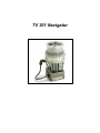 2
2
-
 3
3
-
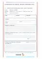 4
4
-
 5
5
-
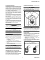 6
6
-
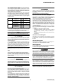 7
7
-
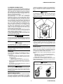 8
8
-
 9
9
-
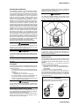 10
10
-
 11
11
-
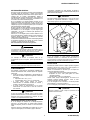 12
12
-
 13
13
-
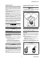 14
14
-
 15
15
-
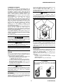 16
16
-
 17
17
-
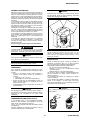 18
18
-
 19
19
-
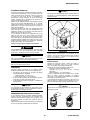 20
20
-
 21
21
-
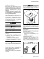 22
22
-
 23
23
-
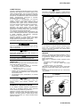 24
24
-
 25
25
-
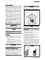 26
26
-
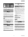 27
27
-
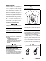 28
28
-
 29
29
-
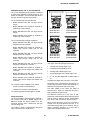 30
30
-
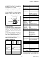 31
31
-
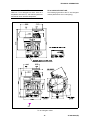 32
32
-
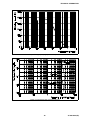 33
33
-
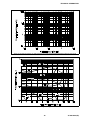 34
34
-
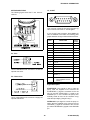 35
35
-
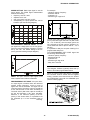 36
36
-
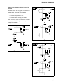 37
37
-
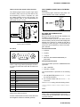 38
38
-
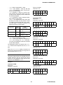 39
39
-
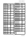 40
40
-
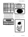 41
41
-
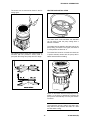 42
42
-
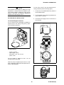 43
43
-
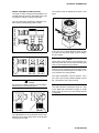 44
44
-
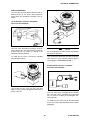 45
45
-
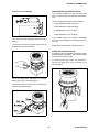 46
46
-
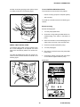 47
47
-
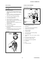 48
48
-
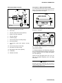 49
49
-
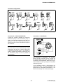 50
50
-
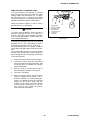 51
51
-
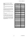 52
52
-
 53
53
-
 54
54
-
 55
55


Varian TV 301 Navigator 969-8827 Manual de usuario
- Tipo
- Manual de usuario
En otros idiomas
- français: Varian TV 301 Navigator 969-8827 Manuel utilisateur
- English: Varian TV 301 Navigator 969-8827 User manual
- Nederlands: Varian TV 301 Navigator 969-8827 Handleiding
- português: Varian TV 301 Navigator 969-8827 Manual do usuário
- dansk: Varian TV 301 Navigator 969-8827 Brugermanual
- svenska: Varian TV 301 Navigator 969-8827 Användarmanual
- suomi: Varian TV 301 Navigator 969-8827 Ohjekirja
Documentos relacionados
-
Varian TV 301 Navigator Manual de usuario
-
-
-
-
-
Varian 969-8903 Manual de usuario
-
-
-
-
Varian 969-9126 Instructions For Use Manual