Pepperl+Fuchs LC10-1-D 230 VAC Instrucciones de operación
- Tipo
- Instrucciones de operación

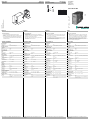
Abmessungen: Dimensions:
Construzione: Dimensiones:
alle Maße in mm
All dimensions are in mm
Tutte le dimensioni sono indicate in mm
Todas las dimensiones son en mm
Anschluss: Connection type:
Allacciamento elettrico: Conexión:
Deutsch English ItaliaEspañol
Weitere Angaben siehe Katalog „Optoelektronische Sensoren“ For further information refer to the "Photoelectric Sensors"
catalogue
Per ulteriori dati vedere il catalogo "Sensori optoelettronici" Puede encontrar otras informaciones en el Catálogo "Sensores
fotoeléctricos"
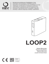
Sicherheitshinweise:
• Vor der Inbetriebnahme Betriebsanleitung lesen
• Anschluss, Montage und Einstellung nur durch Fachper-
sonal
• Kein Sicherheitsbauteil gemäß EU-Maschinenrichtlinie,
darf nicht für Personenschutz oder NOT-AUS-Funktion
verwendet werden.
Technical data
Technische Daten Dati tecniciDatos técnicos
Security Instructions:
• Read the operating instructions before attempting
commissioning
• Installation, connection and adjustments should only be
undertaken by specialist personnel
• No safety component for protection of personnel or
EMERGENCY-STOP functions.
Avvertenze di sicurezza
• "Prima della messa in funzione, leggere le istruzioni per
l'uso.
• "Gli interventi di collegamento, montaggio e regolazione
devono essere effettuati solo da personale specializzato.
• "Non si tratta di un componente di sicurezza conforme
alla Direttiva UE "Macchine", pertanto non è consentito il
suo utilizzo per la protezione delle persone o per la
funzione di arresto d'emergenza.
Indicación de sguridad:
• Antes de la puesta en marcha leer las indicaciones de
uso.
• La conexión, el montaje y los ajustes deben roalizarse
sólo por personal cualificado.
• No es ningún elemento de seguridad según las normas
CE que pueda utilizarse para protección de personas o
como función de paro de emergencia.
78
6
4
1
10
5
11
3
2
4
5
6
3
Number Explanation Connector
terminals
3 Loop connection 7/8
4 Signal output, 5/6 = NO
maintained contact 6/10 = NC
5 Signal output, 3/4 = NO
pulse contact 4/11 = NC
6 Operating voltage 1/2
75
37.5
27
71
Schleifendetektor
Loop detector
Detector de bucle
Rilevatore di loop
LC10-1-D 230 VAC
Allgemeine Daten
Kennzeichnung CE
Betriebsart Impuls- und Dauersignal
Kenndaten funktionale
Sicherheit
MTTFd 306 a
Gebrauchsdauer (TM) 20 a
Anzeigen/Bedienele-
mente
Bedienelemente DIP-Schalter
Schaltzustand LED
Elektrische Daten
Betriebsspannung UB230 V AC ( galvanisch getrennt von Schleife )
Welligkeit -15 %/+10 %
Leistungsaufnahme P01,6 VA
Abgleichzeit 2 s
Schleifeninduktivität 100 ... 1000
µ
H
Schleifenfrequenz 20 ... 120 kHz
Eingang
Kanalanzahl 1
Ausgang
Ausgangstyp Relais
Schaltspannung 250 V AC
Schaltstrom 6 A
Impulsdauer Dauer oder 800 ms Impuls
Ansprechzeit 100 ms
Umgebungsbedingungen
Umgebungstemperatur -20 ... 70 °C (-4 ... 158 °F)
Lagertemperatur -40 ... 70 °C (-40 ... 158 °F)
Mechanische Daten
Schutzart IP30
Anschluss Stecksockel ; 11-poliger Klemmanschluss
≤
1,5 mm2
General specifications
Marking CE
Operating mode Pulsed and continuous signal
Functional safety related
parameters
MTTFd 306 a
Mission Time (TM) 20 a
Indicators/operating
means
Controls DIP-switch
Switching state LED
Electrical specifications
Operating voltage UB230 V AC ( galvanically isolated from loop )
Ripple -15 %/+10 %
Power consumption P01.6 VA
Calibration time 2 s
Loop inductivity 100 ... 1000
µ
H
Loop frequency 20 ... 120 kHz
Input
Number of channels 1
Output
Output type relay
Switching voltage 250 V AC
Switching current 6 A
Pulse length period or 800 ms Pulse
Response time 100 ms
Ambient conditions
Ambient temperature -20 ... 70 °C (-4 ... 158 °F)
Storage temperature -40 ... 70 °C (-40 ... 158 °F)
Mechanical specifications
Protection degree IP30
Connection Plug socket ; 11-pin Terminal connection
≤
1.5
mm2
Dati generali
Marcatura CE
Modo operativo Segnale ad impulsi e segnale continuo
Caratteristiche sicurezza
funzionale
MTTFd 306 a
Durata del'utilizzo (TM) 20 a
Indicatori / Elementi di
comando
Elementi di comando DIP switch
Stato elettrico LED
Dati elettrici
Tensione di esercizio UB230 V AC ( a separazione galvanica dal loop
)
Ondulazione -15 %/+10 %
Consumo (di potenza) P01,6 VA
Tempo di taratura 2 s
Induttività del loop 100 ... 1000
µ
H
Frequenza di loop 20 ... 120 kHz
Ingresso
Numero de canale 1
Uscita
Tipo di uscita Relè
Tensione di comando 250 V AC
Corrente di comando 6 A
Durata degli impulsi Costante o 800 ms impulso
Tempo di reazione 100 ms
Condizioni ambientali
Temperatura ambiente -20 ... 70 °C (-4 ... 158 °F)
Temperatura di magazzinag-
gio
-40 ... 70 °C (-40 ... 158 °F)
Dati meccanici
Classe di protezione IP30
Allacciamento Zoccolo ad innesto ; a 11 poli Collegamento a
morsetto
≤
1,5 mm2
Datos generales
Caracteristicas CE
Modo operativo Señal de impulso y permanente
Datos característicos de
seguridad funcional
MTTFd 306 a
Duración de servicio (TM) 20 a
Elementos de indicación
y manejo
Elementos de mando Conmutador DIP
Estado de conmutación LED
Datos eléctricos
Tensión de trabajo UB230 V CA ( con aislamiento galvánico del
bucle )
Rizado -15 %/+10 %
Consumo de potencia P01,6 VA
Tiempo de ajuste 2 s
Inductancia del bucle 100 ... 1000
µ
H
Frecuencia del bucle 20 ... 120 kHz
Entrada
Cantidad de canales 1
Salida
Tipo de salida Relé
Tensión de conmutación 250 V CA
Corriente de conmutación 6 A
Duración del impulso Duración o 800 ms Impulso
Tiempo de respuesta 100 ms
Condiciones ambientales
Temperatura ambiente -20 ... 70 °C (-4 ... 158 °F)
Temperatura de almacenaje -40 ... 70 °C (-40 ... 158 °F)
Datos mecánicos
Tipo de protección IP30
Conexión Base conectora ; 11 polos Conexión a termi-
nales
≤
1,5 mm2
07/08/2013
Date: DIN A3 -> DIN A7
Part. No.: 190924 45-2820A
Doc. No.:

Adressen / Addresses / Adresses / Direcciónes / Indirizzi Adressen / Addresses / Adresses / Direcciónes / Indirizzi
Contact Pepperl+Fuchs GmbH · 68301 Mannheim · Germany · Tel. +49 621 776-1111 · Fax +49 621 776-27-1111 · E-mail: fa-info@de.pepperl-fuchs.com USA Headquarters: Pepperl+Fuchs Inc. · Twinsburg · USA · E-mail: [email protected]l-fuchs.com
Worldwide Headquarters: Pepperl+Fuchs GmbH · Mannheim · Germany · E-mail: fa-info@pepperl-fuchs.com Asia Pacific Headquarters: Pepperl+Fuchs Pte Ltd · Singapore · E-mail: fa-info@sg.pepperl-fuchs.com
For more contact-adresses refer to the catalogue or internet: http://www.pepperl-fuchs.com
Zusätzliche Informationen, Kennlinien, Hinweise
Informazioni, caratteristiche, avvertenze aggiuntive
Additional information; characteristic curves, notes
Información adicional, lineas caracteristicas, notas
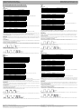
Anschluss:
Einstellungen:
Empfindlichkeit:
Die Ansprechempfindlichkeit des Schleifendetektors kann in drei Stufen durch die Schalter 3 und 4 eingestellt werden.
Bei Schalterstellung "OFF", "OFF" ist die Schleifenauswertung abgeschaltet.
Frequenzschalter:
Die Schleifenfrequenz kann in vier Stufen über die Schalter 1 und 2 eingestellt werden.
Nach dem Betätigen der Frequenzschalter 1 und 2 muss die Schleife in der Stellung "OFF", "OFF" der Schalter 3 und 4 neu abge-
glichen werden.
Betriebsartenschalter:
Mit den Schalter 5 und 6 können folgende Betriebsarten eingestellt werden:
Die Empfindlichkeitsanhebung (Boost) dient zum Erkennen von Fahrzeugen mit hohen Aufbauten z.B. von LKWs.
Automatischer Abgleich:
Wird die Betriebsspannung an das Gerät angelegt, erfolgt ein automatischer Abgleich mit der Schleife. Die Ausgangsrelais werden
in die Schaltstellung "Schleife nicht belegt" geschaltet. Der Abgleich dauert 2 s, danach ist Gerät betriebsbereit.
Ein automatischer erfolgt auch, wenn beide Empfindlichkeitsschalter 3 und 4 auf "OFF" geschaltet und danach in eine andere Schal-
terstellung gebracht werden.
Anzeigen:
Durch die LED 2 wird der Belegungszustand der Schleife signalisiert (Schleife belegt = LED ein). Eine Störung der Schleife durch
Kurzschluss oder Unterbrechung und eine Schleifeninduktivität außerhalb des zulässigen Bereichs wird durch Blinken der LED 2 si-
gnalisiert.
Testfunktion:
Der Schleifendetektor ist mit einer integrierten Testfunktion ausgestattet, welche eine optimale Einstellung von Schleifenfrequenz
und Empfindlichkeit ohne zusätzliche Messtechnik ermöglicht.
Anzeige der empfohlenen Empfindlichkeit:
Dazu muss mit dem Fahrzeug auf die Schleife gefahren werden. Der Schleifendetektor misst und speichert die erzeugte Frequen-
zänderung. Durch Umschalten der beiden Schalter 3 und 4 wird die empfohlene Empfindlichkeit durch Blinken der LED angezeigt.
Messung der Schleifenfrequenz:
Über die LED kann eine Messung der Schleifenfrequenz erfolgen. Dazu die Schalter 3 und 4 von "OFF" auf "ON" schalten. Die LED
zeigt durch eine Signalfolge die Schleifenfrequenz an:
Schleifenstörung:
Bei Unterbrechung oder Kurzschluss blinkt die LED-Anzeige ständig und der Schaltkontakt geht in den Zustand "Schleife belegt".
Connection:
Settings:
Sensitivity:
The response sensitivity of the loop detector can be set in three stages by switches 3 and 4.
In the switch position "OFF", "OFF" the loop evaluation is switched off.
Frequency switches:
The loop frequency can be set in four stages using the switches 1 and 2.
After actuation of the frequency switches 1 and 2 the loop must be readjusted with switches 3 and 4 set to "OFF", "OFF".
Operating mode switches:
The following operating modes can be set with switches 5 and 6:
The increased sensitivity (Boost) is used for the detection of vehicles with high body assemblies, e.g. HGVs.
Automatic adjustment:
When the operating voltage is applied to the device automatic adjustment with the loop takes place. The output relays are switched
in the switch position "Loop not allocated". The adjustment takes 2 s, the device is then ready for operation.
Automatic adjustment also takes place when both sensitivity switches 3 and 4 are set to "OFF" and then set to another switch position.
Indications:
LED 2 signals the allocation state of the loop (Loop allocated = LED On). A fault in the loop due to a short-circuit or lead breakage
and loop inductance outside the permissible range is indicated by flashing of LED 2.
Test function:
The loop detector is provided with an integrated test function, which enables the loop frequency and sensitivity to be optimally set
without additional devices or instrumentation.
Indication of the recommended sensitivity:
The vehicle must be driven onto the loop. The loop detector measures and stores the frequency change. When switches 3 and 4 are
changed over the recommended sensitivity is indicated by flashing of the LED.
Measurement of the loop frequency:
The loop frequency can be measured via the LED. Set switches 3 and 4 from "OFF" to "ON". The LED indicates the loop frequency
via a signal sequence:
Loop fault:
In the event of lead breakage or short-circuit the LED flashes continuously and the switch contact reverts to the "Loop allocated" state.
Conexión:
Ajustes:
Sensibilidad:
La respuesta de sensibilidad del detector de bucle puede ajustarse en tres niveles mediante los interruptores 3 y 4.
Con el interruptor en la posición "OFF", "OFF" se desconecta la evaluación de bucles.
Interruptor de frecuencias:
Mediante los interruptores 1 y 2 puede ajustarse en niveles la frecuencia de bucle.
Tras accionar el interruptor de frecuencia 1 y 2 deberá volver ajustarse el bucle en la posición "OFF", "OFF" del interruptor 3 y 4.
Interruptor modo de trabajo:
Mediante los interruptores 5 y 6 pueden ajustarse los siguientes modos de trabajo:
La acentuación de la sensibilidad (Boost) permite reconocer vehículos altos p.ej. camiones.
Ajuste automático:
Si se coloca la tensión de trabajo al aparato, se realiza un ajuste automático con el bucle. Se conmutan los relés de salida a la po-
sición "bucle no ocupado". El ajuste tarda 2 s, y el aparato está listo para operar.
Un ajuste automático se produce también si ambos interruptores de sensibilidad 3 y 4 están en "OFF" y después son recolocados a
otra posición.
Indicadores:
Mediante el LED 2 se señaliza el estado de ocupación del bucle (bucle ocupado = LED on). Una perturbación del bucle por un cor-
tocircuito o una interrupción y una inductancia del bucle fuera del rango permitido se señaliza mediante intermitencias del LED 2.
Functión de Test:
El detector de bucle está provisto con una función de test integrada, la cual posibilita un ajuste óptimo de frecuencias y sensibilidad
de bucle sin necesidad de efectuar mediciones adicionales.
Indicación de la sensibilidad recomendada:
Dirigir el vehículo encima del bucle. El detector de bucle mide y almacena los cambios de frecuencia que se hayan producido. Por
la inversión de ambos interruptores 3 y 4 se indica la sensibilidad recomendada a través del parpadeo del LED.
Medición de la frecuencia del bucle:
A través del LED puede realizarse una medición de la frecuencia del bucle. Deben colocarse los interruptores 3 y 4 de "OFF" a "ON".
El LED indica con una serie de señales la frecuencia del bucle:
Perturbación del bucle:
Con interrupción o cortocircuito el Display por LED parpadea constantemente y el contacto de conmutación pasa al estado "bucle
ocupado".
Allacciamento:
Regolazioni:
Sensibilità
La sensibilità di risposta del rilevatore a spira può essere regolata in tre posizioni con gli interruttori 3 e 4.
Con gli interruttori in posizione OFF", "OFF" la valutazione della spira è disattivata.
Interruttori di frequenza
La frequenza della spira può essere regolata in quattro posizioni mediante gli interruttori 1 e 2.
Dopo l'azionamento degli interruttori 1 e 2, la spira deve essere regolata nuovamente sulla posizione "OFF", "OFF" degli interruttori
3 e 4.
Interruttori di funzionamento
Con gli interruttori 5 e 6 è possibile regolare le seguenti modalità di funzionamento:
L'aumento della sensibilità (Boost) serve per il riconoscimento di veicoli con struttura alta, per esempio gli autocarri.
Bilanciamento automatico
Qualora all'apparecchio venga applicata la tensione di alimentazione, vi è un bilanciamento automatico con la spira. I relè di uscita
vengono commutati sulla posizione "spira non occupata". Il bilanciamento dura 2 secondi, quindi l'apparecchio è pronto per il funzi-
onamento.
Vi è un bilanciamento automatico anche quando gli interruttori di sensibilità 3 e 4 vengono commutati su "OFF" e quindi portati su
un'altra posizione.
Indicatori:
Mediante il LED 2 viene segnalato lo stato di occupazione della spira (spira occupata = LED acceso). Il LED 2 lampeggia per seg-
nalare il malfunzionamento della spira dovuto a cortocircuito o interruzione e l'induttanza della spira al di fuori dell'ambito consentito.
Prova di funzionamento:
Il rilevatore a spira è dotato di una prova di funzionamento integrata che consente una regolazione ottimale della frequenza e della
sensibilità senza ulteriori tecniche di misurazione.
Indicatore della sensibilità raccomandata
Transitando con il veicolo sulla spira il rilevatore misura e immagazzina le variazioni di frequenza generate. Mediante la commutazi-
one degli interruttori 3 e 4 il LED lampeggia per indicare la sensibilità raccomandata.
Misurazione della frequenza nella spira
Mediante il LED è possibile misurare la frequenza della spira spostando gli interruttori 3 e 4 da "OFF" a "ON". Il LED indica la fre-
quenza attraverso una sequenza di segnali:
Malfunzionamento della spira
In caso di interruzione o cortocircuito il LED lampeggia continuamente e il contatto di commutazione si posiziona su "spira occupata".
Nummer Erläuterung Anschlussklemmen
3Schleifenanschluss 7/8
4Signalausgang Dauerkontakt 5/6 = Schließer 6/10 = Öffner
5Signalausgang Impulskontakt 3/4 = Schließer 4/11 = Öffner
6Betriebsspannung 1/2
Schalter 3 Schalter 4 Empfindlichkeit
OFF ON gering
ON OFF mittel
ON ON hoch
Schalter 1 Schalter 2 Frequenz
OFF OFF Grundfrequenz f
ON OFF f - 10 %
OFF ON f - 15 %
ON ON f - 20 %
Schalter 5 Schalter 6 Bedeutung
OFF -Impuls (0,8 s) bei Belegung der Schleife
ON -Impuls (0,8 s) bei Verlassen der Schleife
-ON Empfindlichkeitsanhebung (Boost)
Number Explanation Connector terminals
3Loop connection 7/8
4Signal output, maintained contact 5/6 = NO 6/10 = NC
5signal output, pulse contact 3/4 = NO 4/11 = NC
6Operating voltage 1/2
Switch 3 Switch 4 Sensitivity
OFF ON low
ON OFF medium
ON ON high
Switch 1 Switch 2 Frequency
OFF OFF Basic frequency f
ON OFF f - 10 %
OFF ON f - 15 %
ON ON f - 20 %
Switch 5 Switch 6 Result
OFF -Pulse (0,8 s)when loop is allocated
ON -Pulse (0,8 s) when loop is abandoned
-ON Increased sensitivity (Boost)
Beschreibung/Desciption/Descripción/Descrizione
Empfindlichkeitsstufe 3
einstellen
LED
123
Schleifenfrequenz
33 kHz
LED
123
Adjust sensitivity step
LED
123
Loop frequency 33 kHz
LED
123
Número Leyenda Terminales de conexión
3Conexión a bucles 7/8
4Salida señal Contacto permanente 5/6 = N.A. 6/10 = N.C.
5Salida señal Contacto impulso 3/4 = N.A. 4/11 = N.C.
6Tensión de trabajo 1/2
Interruptor 3 Interruptor 4 Sensibilidad
OFF ON bajo
ON OFF medio
ON ON alto
Interruptor 1 Interruptor 2 Frecuencia
OFF OFF Frecuencia base f
ON OFF f - 10 %
OFF ON f - 15 %
ON ON f - 20 %
Interruptor 5 Interruptor 6 Significado
OFF -Impulso (0,8 s) al ocupar el bucle
ON -Impulso (0,8 s) al abandonado el bucle
-ON Acentuación de la sensibilidad (Boost)
Numero Spiegazione Morsetti di collegamento
3Collegamento spira 7/8
4Uscita segnale - contatto continuo 5/6 = normalmente aperto - 6/10 = normalmente chiuso
5Uscita segnale - contatto a impulsi 3/4 = normalmente aperto - 4/11 = normalmente chiuso
6Tensione di alimentazione 1/2
Interruttore 3 Interruttore 4 Sensibilità
OFF ON basso
ON OFF medio
ON ON alto
Interruttore 1 Interruttore 2 Frequenza
OFF OFF Frequenza di base f
ON OFF f - 10 %
OFF ON f - 15 %
ON ON f - 20 %
Interruttore 5 Interruttore 6 Significato
OFF -Impulso (0,8 s) con spira occupata
ON -Impulso (0,8 s) con spira abbandonato
-ON Aumento della sensibilità (Boost)
Ajustar nivel
de sensibilidad 3
LED
123
Frecuencia
de lazo 33 kHz
LED
123
Regolazione del
livello di sensibilità 3
LED
123
Frequenza di loop
33 kHz
LED
123
-
 1
1
-
 2
2


Pepperl+Fuchs LC10-1-D 230 VAC Instrucciones de operación
- Tipo
- Instrucciones de operación
en otros idiomas
Artículos relacionados
Otros documentos
-
 Key Automation 580LOOP2 Manual de usuario
-
Genius RMG1 RMG2 Instrucciones de operación
-
-
JCM Magnetic Vehicle Detector Guía del usuario
-
CARLO GAVAZZI LDP2PA2DU24 El manual del propietario
-
Marantec Control 400 El manual del propietario
-
-
PRASTEL MLX24V Manual de usuario
-
Nice Automation M-Bar and L-Bar El manual del propietario
