Twin-Star International 26DE1247 Instruction Manual Enclosed
- Tipo
- Instruction Manual Enclosed

ATTENTION
IF YOU HAVE ANY PROBLEMS OR QUESTIONS, EMAIL
OR CALL CUSTOMER SERVICE BEFORE YOU RETURN
THIS PRODUCT TO THE STORE WHERE IT WAS PURCHASED.
For Customer Service: email: par[email protected]
in English Call: 866-661-1218
in Spanish Call: 866-661-1218
in French Call: 866-374-9203
ATENCIÓN
SI TIENE ALGÚN PROBLEMA O PREGUNTAS,
ENVÍE UN MENSAJE DE CORREO ELECTRÓNICO O LLAME AL SERVICIO
DE ATENCIÓN AL CLIENTE ANTES DE DEVOLVER
ESTE PRODUCTO A LA TIENDA EN LA QUE LO COMPRÓ.
Servicio de atención al cliente: Correo electrónico: par[email protected]
Línea para llamadas en inglés: 866-661-1218
Línea para llamadas en español: 866-661-1218
Línea para llamadas en francés: 866-374-9203
STOP
STOP
PARE
PARE
ATTENTION
SI VOUS AVEZ DES PROBLÈMES OU QUESTIONS,
ENVOYEZ UN COURRIEL AU SERVICE À LA CLIENTÈLE OU APPELEZ LE
SERVICE À LA CLIENTÈLE AVANT DE RETOURNER
CE PRODUIT OÙ VOUS L’AVEZ ACHETÉ.
Pour le service à la clientèle : courriel : par[email protected]
pour le service en anglais, composez le 866-661-1218
pour le service en espagnol, composez le 866-661-1218
pour le service en français, composez le 866-374-9203
ARRÊT
ARRÊT
INSTRUCTION MANUAL ENCLOSED
MANUEL D’INSTRUCTION À L’INTÉRIEUR
MANUAL DE INSTRUCCIONES ADJUNTO
INSTRUCTION MANUAL ENCLOSED
MANUEL D’INSTRUCTION À L’INTÉRIEUR
MANUAL DE INSTRUCCIONES ADJUNTO

E-1
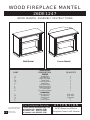
WOOD FIREPLACE MANTEL
WOOD MANTEL ASSEMBLY INSTRUCTIONS
26DE1247
ATTENTION
For Customer Service:
ALSO Requires-Electric
Fireplace Insert with Heater
E-mail: [email protected]
In English call: 866-661-1218
In French call: 866-374-9203
In Spanish call: 866-661-1218
Twin-Star International, Inc.
Delray Beach, FL 33445
Made in China
Printed in China
Wall Mantel Corner Mantel
PARTS LIST
PART DESCRIPTION QUANTITY
PARTS
Hearth/Base
Left Side Panel
Right Side Panel
Center Shelf
Center Top Panel
Mantel/Top
Left Front Panel
Right Front Panel
Center Back Panel
"L" corner brace
Top corner extension
HARDWARE
Bolt 1/4"x1-1/4"
Flat Washer
Wood Dowel
Screw
Touch-Up Pen
A
B
C
D1
D2
G
I
J
K
P
R
L
M
N
Q
Z
1
1
1
1
1
1
1
1
1
1
1
28+1 extra
28+1 extra
25+1 extra
18
1

E-2
PLEASE READ AND FOLLOW ALL SAFETY TIPS
GETTING STARTED
1. Before assembly, CAREFULLY use scissors or utility knife to cut and unwrap all parts. Make sure you do
not discard the hardware.
2. Make sure that you have all the parts listed. If you are missing any parts please email Customer Service:
[email protected] or call 1-866-661-1218 in English, 1-866-374-9203 in French or
1-866-661-1218 in Spanish. Please identify the parts you need and model number. Make sure to include
your name and address.
CAUTION:
DO NOT MOVE MANTEL OR INSERT WHILE PLUGGED INTO POWER SUPPLY.
HELPFUL HINTS
• Some steps are more easily handled with two adults.
• Attach the fi replace insert to the completed wood mantel last. INSTALL INSERT IN FROM THE BACK
OF THE FIREPLACE SO AS NOT TO SCRATCH THE HEARTH/BASE.
• Use care in assembling your new fi replace, take your time and use the hardware provided and a quality
Phillips head screwdriver. NEVER OVER TIGHTEN BOLTS.
• Do not sit on any part of the mantel.
CARE & CLEANING
1. Dust your fi replace regularly with a soft non-lint producing cloth or household dusting product.
2. You can clean your fi replace with a gentle non-abrasive household cleaner. Make sure to dry your
fi replace immediately with a soft cloth or towel.
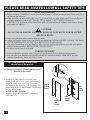
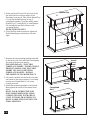
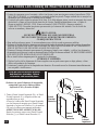
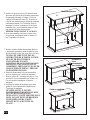
1. Locate Left Side Panel (B) and Left Front
Panel (I) and set out on a scratch free surface.
Align the holes in the Left Front Panel with
the mounting blocks on the Left Side Panel and
attach using Bolts (L) and Washers (M) through
the pre-drilled holes.
HAND TIGHTEN ONLY.
Repeat with Right Front Panel (J) and Right
Side Panel (C)
Left
Side
Panel
Left
Front
Panel
Right
Side
Panel
Right
Front
Panel
C
I
L
J
M
B
For a complete tight fi t every bolt
should have a fl at washer.
All panels are labeled Left and Right as viewed
from the front of unit.

E-3
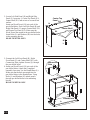
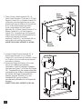
2. Locate Left Side Panel (B) and Right Side
Panel (C) from step 1, Center Top Panel (D2),
Center Shelf (D1) and set out on a scrach free
surface.
Insert one Wood Dowel (N) into each of the
pre-drilled holes. Push Left Side Panel (B) and
Right Side Panel (C) snug to Center Shelf (D1)
and Center Top Panel (D2). Make sure the
Wood Dowel are seated in the pre-drilled holes.
Insert Bolts (L) and Washers (M) into the holes
in the mounting blocks.
HAND TIGHTEN ONLY.
3. Connect the Left Front Panel (B), Right
Front Panel (C) and Center Shelf (D1) with
Connection Plate, tighten Screws (Q) through
the pre-drilled holes.
4. Insert one Wood Dowel (N) into each of the
pre-drilled holes. Attach the Completed
assembly from step 3 to the Hearth/Base (A).
Make sure that dowels are seated into the
pre-drilled holes in the Hearth/Base. Using
Bolts (L) and Washers (M) attach panels
through pre-drilled holes in the mounting
blocks.
HAND TIGHTEN ONLY.
N
L
Q
M
A
N
N
N
N
NN
N
N
N
N
N
L
M
N
D1
B
C
D2
Center Shelf
Center Top
Panel
Connection
Plate
Hearth/Base

E-4
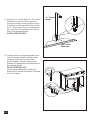
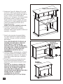
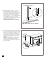
5. Insert one Wood Dowel (N) into each of the
pre-drilled holes on the top edges of the
Assembly from step 4. Then locate Mantel/Top
(G) and lay fi nished side up on top of
completed assembly. From the inside, attach
Mantel/Top (G) using Bolts (L) and Washers
(M) through the pre-drilled holes in the
mounting blocks.
HAND TIGHTEN ONLY.
6. Using Phillips head screwdriver tighten all
Bolts alternating top and bottom, left and
right.
N
N
N
N
G
Mantel/Top
L
M
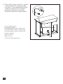
7. Remove the two mounting brackets attached
to the back of the Left and Right Front panels.
Set aside with the wood screws.
PLEASE READ ALL “ELECTRIC
FIREPLACE INSERT” INSTRUCTIONS
PRIOR TO INSTALLING ELECTRIC
INSERT IN YOUR COMPLETED
FIREPLACE MANTEL. INSTALL
THE INSERT IN YOUR FIREPLACE
8. Lift insert carefully into the back of the unit
and center in the insert opening. Do not drag
insert across Hearth/Base (A) as it may
scratch your unit.
9. Install the mounting brackets to hold insert
fl ush against the inside of the mantel front
panel.
MOVE YOUR COMPLETED UNIT
ONLY SHORT DISTANCES. MOVE
COMPLETED UNIT WITH GREAT
CARE. IT TAKES TWO PEOPLE TO
MOVE COMPLETED UNIT INTO ITS
FINAL POSITION.
Completed
Unit
Electric Fireplace
Insert
Install
Insert
From
Back

E-5
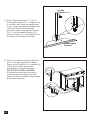
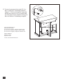
10. Locate the “L” Corner Brace (P), Top Corner
Extension (R) and set out face down on a
scratch-free surface. Insert one Wood Dowel
(N) into each of the pre-drilled holes. Attach
the “L” Brace snug to Top Corner Extension
(R), insert Bolt (L) and Washer (M) into the
holes in the mounting blocks.
HAND TIGHTEN ONLY.
"L" Corner
Brace
Top Corner
Extension
R
P
N
M
L
N
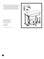
11. Carefully slide the Complete assembly from
step 10 into place at back of Mantel. Insert
one Wood Dowel (N) into each of the
pre-drilled holes. Then use Bolts (L) and
Washers (M) through the pre-drillled holes in
the mounting blocks.
HAND TIGHTEN ONLY.
Now you may tighten down all the bolts
holding the Corner Back assembly. Be careful
not to over tighten.
N
N
L
M

E-6
Twin-Star International, Inc.
Delray Beach, FL 33445
In English: 1-866-661-1218
In French: 1-866-374-9203
In Spanish: 1-866-661-1218
Model# 26DE1247
Made in China
Printed in China
2010,Twin-Star International, Inc.
12. Locate Center Back Panel (K), attach to the
back of the completed assembly from step 11.
Use a Phillips Head screw driver, tighten
screws (Q) through the pre-drilled holes in
the Back Panels to the completed assembly.
K
Q
Q
Center Back
Panel

S-1
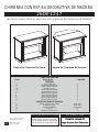
CHIMENEA CON REPISA DECORATIVA DE
MADERA
INSTRUCCIONES PARA EL MONTAJE DE LA REPISA DECORATIVA DE MADERA
26DE1247
Repisa De Chimenea De Pared Repisa De Chimenea De Esquina
LISTA DE PIEZAS
Pieza Descripción Cantidad
PIEZAS
Base Del Hogar
Panel Lateral Izquierdo
Panel Lateral Derecho
Estante Central
Panel Superior Central
Repisa/Parte Supeiror
Panel Frontal Izquierdo
Panel Frontal Derecho
Panel Trasero Central
Soporte Angular En “L”
Pieza Angular Superior
ELEMENTOS PARA EL MONTAJE
Tornillo 1/4 Pulg. X 1/4 Pulg.
Arandela ¼ Pulg.
Espiga De Madera
Tornillo
Bolígrafo Para Retocar
A
B
C
D1
D2
G
I
J
K
P
R
L
M
N
Q
Z
1
1
1
1
1
1
1
1
1
1
1
28+1 extra
28+1 extra
25+1 extra
18
1
Necesitará, Además, El
Necesitará, Además, El
Hogar Eléctrico Con Calentador
Hogar Eléctrico Con Calentador
Correo electrónico: [email protected]
Línea para llamadas en inglés: 866-661-1218
Línea para llamadas en francés: 866-374-9203
Línea para llamadas en español: 866-661-1218
ATENCIÓN
Servicio de atención al cliente:
Twin-Star International, Inc.
Delray Beach, FL 33445
Fabricado en China
Impreso en China

S-2
C
I
L
J
M
B
A fi n de que los tornillos queden
debidamente ajustados, deberá
colocarles una arandela plana.
Si observa la parte Delantero de los paneles,
comprobará que en los lados se indica
Izquierda (Left) y Derecha (Right).
LEA TODOS LOS CONSEJOS PRÁCTICOS DE SEGURIDAD
COMIENZO
1. Antes de comenzar con el montaje, utilice las tijeras o una navaja para cortar el envoltorio CON
MUCHO CUIDADO y, a continuación, extraiga todas las piezas. Tenga cuidado de no arrojar los
elementos que utilizará en el montaje de la unidad.
2. Controle que estén todas las piezas de la lista. Si le falta alguna pieza, envíe un mensaje de correo
electrónico o llame a Servicios de atención al cliente: [email protected], o llame al:
(línea en inglés)1-866-661-1218; (línea en francés)1-866-374-9203; (línea en español)
1-866-661-1218. Describa las piezas que necesita y el número del modelo. No se olvide de
colocar su nombre y dirección.
PRECAUCIÓN:
NO MUEVA LA REPISA NI EL HOGAR MIENTRAS
ESTÁN CONECTADOS AL SUMINISTRO DE ENERGÍA.
CONSEJOS PRÁCTICOS
• Para realizar algunos pasos, le recomendamos que solicite ayuda a personas adultas.
• Coloque el hogar eléctrico una vez que haya terminado de montar la repisa decorativa de madera.
INSTALE EL HOGAR ELÉCTRICO DESDE LA PARTE POSTERIOR DE LA CHIMENEA A
FIN DE EVITAR QUE SE DAÑE LA BASE DEL HOGAR.
• Tómese el tiempo necesario para armar la chimenea, hágalo con cuidado, y utilice los elementos
de montaje provistos así como un destornillador Phillips de buena calidad. LE RECOMENDAMOS
QUE NO AJUSTE DEMASIADO LOS TORNILLOS.
• No se siente sobre ninguna parte la repisa de la chimenea.
CUIDADO Y LIMPIEZA
1. Quite el polvo de la chimenea de forma regular con un paño suave que no deje pelusa, o bien
utilice un producto de limpieza.
2. Asimismo, puede aplicar un limpiador no abrasivo. Recuerde secar la chimenea inmediatamente
con un paño o toalla suave.
1. Tome el Panel Lateral Izquierdo (B) y el Panel
Frontal Izquierdo (I) y ubíquelos sobre una
superfi cie que no raye.
Alinee los orifi cios del Panel Frontal Izquierdo
con los bloques de montaje en el Panel Lateral
Izquierdo y sujete con Tornillos (L) y Arandelas
(M) en los orifi cios previamente perforados.
APRIETELOS SOLAMENTE A MANO.
Repita los mismos pasos con el Panel Frontal
Derecho (J) y el Panel Lateral Derecho (C).
Panel
Lateral
Derecho
Panel
Lateral
Izquierdo
Panel
Frontal
Derecho
Panel
Frontal
Izquierdo

S-3
N
L
Q
M
A
N
N
N
N
NN
N
N
N
N
N
L
M
N
D1
B
C
D2
2. Tome el Panel Lateral Izquierdo (B) y el
Panel Lateral Derecho (C) del paso 1, el Panel
Superior Central (D2) y el Estante Central (D1)
y ubíquelos sobre una superfi cie que no raye.
Inserte una Espiga de Madera (N) en cada uno
de los orifi cios previamente perforados.
Ajuste correctamente el Panel Lateral
Izquierdo (B) y el Panel Lateral Derecho (C) al
Estante Central (D1) y al Panel Superior
Central (D2). Compruebe que las Espigas de
Madera estén colocadas correctamente en los
orifi cios previamente perforados.
Inserte un Tornillo (L) y una Arandela (M) en
cada orifi cio de los bloques de montaje.
APRIETELOS SOLAMENTE A MANO.
3. Conecte el Panel Frontal Izquierdo (B), el
Panel Frontal Derecho (C) y el Estante
Central (D1) con la Placa de Conexión; coloque
los Tornillos (Q) en los orifi cios previamente
perforados y ajústelos.
4. Inserte una Espiga De Madera (N) en cada
uno de los orifi cios previamente
perforados. Ajuste el conjunto Delantero,
que armó en el paso 3, a la Base Del Hogar
(A). Compruebe que las espigas estén bien
colocadas en los orifi cios correspondientes
de la Base del Hogar. Para ajustar los
paneles, pase un Tornillos (L) y una
Arandelas (M) por los orifi cios
previamente perforados de los bloques de
montaje.
APRIETELOS SOLAMENTE A MANO.
Panel
Superior
Central
Panel
Lateral
Izquierdo
Panel
Lateral
Derecho
Estante
Central
Base Del Hogar
Panel De Puerta
De Vidrio

S-4
N
N
N
N
N
G
L
M
7. Quite los dos soportes de montaje fi jados
en la parte trasera de los paneles izquierdo
y derecho. Coloque a un lado los tornillos
para madera.
LEA ATENTAMENTE TODAS LAS
INSTRUCCIONES DEL “HOGAR
ELÉCTRICO” ANTES DE SU
INSTALACIÓN EN LA CHIMENEA
DECORATIVA. UBIQUE EL HOGAR
ELÉCTRICO EN LA POSICIÓN
DEFINITIVA DENTRO DE LA
CHIMENEA.
8. Levante el hogar cuidadosamente, colóquelo
en la parte posterior de la unidad y céntrelo
en la abertura de la chimenea. No empuje el
hogar desde su Base dado que la unidad se
puede dañar.
9. Coloque los soportes de montaje de modo
que el hogar se encuentre nivelado con
respecto a la parte interior del panel frontal
de la repisa.
MUEVA LA UNIDAD COMPLETA
SÓLO EN DISTANCIAS CORTAS.
MUEVA LA UNIDAD COMPLETA
CON MUCHO CUIDADO. SE
NECESITAN DOS PERSONAS PARA
DESPLAZAR LA UNIDAD
COMPLETA AL LUGAR
DEFINITIVO QUE VA A OCUPAR.
Instalar El
Hogar Desde
La Parte
Posterior
Hogar Eléctrico
Para Chimenea
Unidad
Terminada
5. Inserte una Clavija De Madera (N) en cada
uno de los orifi cios previamente perforados
del borde superior del Conjunto que armó en
el paso 4. Luego, tome la Repisa/Parte
Supeiror (G) y colóquela, con el lado acabado
hacia arrinba, sobre el conjunto armado.
Desde el interior, ajuste la Repisa colocando
un Tornillos (L) y una Arandelas (M) en los
orifi cios previamente perforados de los
bloques de montaje.
APRIETELOS SOLAMENTE A MANO.
6. Utilizando un destornillador Phillips
(cruciforme), apriete todos los pernos,
alternando entre la parte superior e inferior, la
izquierda y la derecha.
Repisa/Parte Supeiror

S-5
R
P
N
Soporte
Angular en "L"
Pieza Angular
Superior
M
L
N
N
N
L
M
10. Tome el Soporte Angular En “L” (P) y la
Pieza Angular Superior (R), y colóquelos con
la cara hacia abajo, sobre una superfi cie que
no raye. Inserte una Espiga De Madera (N) en
cada uno de los orifi cios previamente
perforados. Ajuste correctamente el Soporte
En “L” a la Pieza Angular Superior (P), e
inserte los Tornillo (L) y las Arandela (M) en
los orifi cios de los bloques de montaje.
11. Deslice con cuidado el Conjunto armado del
paso 10 en la parte posterior de la Repisa.
Luego, coloque Tornillos (L) y Arandelas (M)
a través de los orifi cios previamente
perforados de los bloques de montaje.
AJUSTE SÓLO MANUALMENTE.
A continuación, ajuste todos los tornillos
mientras sostiene el conjunto de la Pieza
Angular Posterior del mueble. Tenga cuidado
de no ajustar demasiado.

S-6
K
Panel Trasero Central
Q
Q
Twin-Star International, Inc.
Delray Beach, FL 33445
Línea para llamadas en inglés: 1-866-661-1218
Línea para llamadas en francés: 1-866-374-9203
Línea para llamadas en español: 1-866-661-1218
Modelo N° 26DE1247
Fabricado en China
Impreso en China
© 2010, Twin-Star International, Inc.
12. Tome el Panel Trasero Central (K), y sujételos
a la parte posterior del conjunto que armó
en el paso 11. Con un destornillador Phillips,
coloque los Tornillos (Q) en los orifi cios
previamente perforados de los Paneles
Posteriores y ajústelos al conjunto armado.

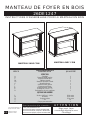
F-1
26DE1247
MANTEAU DE FOYER EN BOIS
INSTRUCTIONS D’ASSEMBLAGE POUR LE MANTEAU EN BOIS
ATTENTION
Pour le service à la clientèle
:
Exige aussi -foyer
encastrable électrique avec
Chauffage
courriel : [email protected]
pour le service en anglais, composez le 866-661-1218
pour le service en français, composez le 866-374-9203
pour le service en espagnol, composez le 866-661-1218
Twin-Star International, Inc.
Delray Beach, FL 33445
Fabriqué en Chine
Imprimé en Chine
Âtre/base
Panneau latéral gauche
Panneau latéral droit
Tablette centrale
Panneau supérieur central
Manteau/dessus
Panneau avant gauche
Panneau avant droit
Panneau arrière central
Écharpe de coin en « l »
Prolongation du coin supérieur
QUINCAILLERIE
Boulon 1/4 Po x 1-1/4 Po
Rondells
Goujon en bois
Vis
Crayon pour retouches
A
B
C
D1
D2
G
I
J
K
P
R
L
M
N
Q
Z
1
1
1
1
1
1
1
1
1
1
1
28+1 extra
28+1 extra
25+1 extra
18
1
MANTEAU SANS COIN
MANTEAU AVEC COIN
LISTE DES PIÈCES
PIÈCE DESCRIPTION QUANTITÉ
PIÈCES

F-2
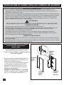
AVANT DE COMMENCER
1. Avant l’installation, utilisez des ciseaux ou un couteau universel pour couper et déballer tous les
composants. Faites ATTENTION de ne pas endommager le manteau. Assurez-vous de ne pas jeter la
quincaillerie d’installation incluse.
2. Assurez-vous d’avoir toutes les pièces indiquées sur la liste. S'il manque des pièces, veuillez envoyer un
courriel au service à la clientèle à l’adresse [email protected] ou composez les numéros suivants :
pour le service en anglais : 1-866-661-1218; pour le service en français : 1-866-374-9203 ou pour le
service en espagnol-866-661-1218. Veuillez indiquer les pièces manquantes ainsi que le numéro de
modèle. Assurez-vous d’inclure vos nom et adresse.
ATTENTION
NE PAS DÉPLACER LE MANTEAU OU LE FOYER TANT QU’IL EST BRANCHÉ.
CONSEILS UTILES
• Certaines étapes seront plus faciles à réaliser avec l’aide d’un autre adulte.
• La dernière étape consistera à lier le manteau entièrement monté au foyer. INSTALLEZ LE FOYER
ENCASTRABLE EN LE DÉPOSANT PAR L’ARRIÈRE DU MANTEAU POUR ÉVITER
D’ÉGRATIGNER L’ÂTRE/BASE DU MANTEAU.
• Faites attention lorsque vous assemblez le foyer et le manteau. Prenez votre temps et utilisez la
quincaillerie fournie, ainsi qu’un tournevis cruciforme. NE PAS TROP SERRER LES BOULONS.
• Ne vous asseyez pas sur aucune partie du manteau!
SOINS ET NETTOYAGE
1. Époussetez régulièrement votre FOYER avec un chiffon doux non pelucheux ou un produit domestique
pour l’époussetage.
2.Vous pouvez nettoyer le foyer avec un nettoyant domestique doux non abrasif. Assurez-vous de l’essuyer
immédiatement avec un linge doux ou une serviette.
VEUILLEZ LIRE ET SUIVRE TOUS LES CONSEILS DE SÉCURITÉ
C
I
L
J
M
B
1. Repérer le panneau latéral gauche (B) et le
panneau avant gauche (I) et les placer sur
une surface parfaitement lisse.
Aligner les trous du panneau avant gauche
avec les blocs de montage situés sur le
panneau latéral gauche et fi xer avec des
boulons (L) et des rondelles (M) passés
dans les trous prépercés.
SERRER UNIQUEMENT À LA MAIN.
Répéter l’opération avec le panneau avant
droit (J) et le panneau latéral droit (C).
Panneau
Latéral
Gauche
Panneau
avant
gauche
Panneau
latéral
droit
Panneau
avant
droit
Pour un assemblage sans jeu, chaque
boulon devrait comporter une
rondelle plate.
Tous les panneaux sont étiquetés Gauche
(« Left ») et Droit (« Right ») à partir d’une vue
de face de l’appareil.

F-3
N
L
A
Q
M
Âtre/Base
N
N
N
N
NN
N
N
N
N
N
L
M
N
D1
B
C
D2
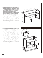
3. Raccorder le panneau avant gauche (B), le
panneau avant droit (C) et la tablette
centrale (D1) au moyen de la plaque de
raccordement, serrer les vis (Q) passées
dans les trous prépercés.
4. Insérer un Goujon En Bois (N) dans chacun
des orifi ces préperforés. Fixer l’assemblage
de la façade déjà complétée à l’étape 3 à la
Base (A). S’assurer que les goujons en
bois sont installés adéquatement dans les
orifi ces préperforés de la base. À l’aide d’un
Boulons (L) et d’une Rondelles (M), fi xer
les panneaux dans les orifi ces préperforés
des blocs de montage.
SERRER UNIQUEMENT À LA MAIN.
2. Repérer le panneau latéral gauche (B) et le
panneau latéral droit (C) montés à l’étape
1, le panneau supérieur central (D2) ainsi
que la tablette centrale (D1) et les placer
sur une surface parfaitement lisse.
Insérer un goujon en bois (N) dans chacun
des trous prépercés. Pousser le panneau
latéral gauche (B) et le panneau latéral droit
(C) contre la tablette centrale (D1) et le
panneau supérieur central (D2). S’assurer
que les goujons en bois sont bien appuyés
dans les trous prépercés.
Insérer des boulons (L) et les rondelles (M)
dans les trous des blocs de montage.
SERRER UNIQUEMENT À LA MAIN.
Tablette centrale
panneau supérieur
central
Plaque De
Connexion

F-4
N
N
N
N
N
G
L
M
Manteau/Dessus
5. Insérez un goujon en bois (N) dans chacun
des trous pré-percés de la bordure supérieure
du panneau assemblé à l’étape 4. Trouvez
ensuite le Manteau/Dessus (G). Déposez le
côté fi ni du manteau sur le dessus du panneau
entièrement monté. De l’intérieur, fi xez le
manteau à l’aide d’un boulons (L) et d’une
rondelles (M), en les insérant dans les trous
pré-percés des blocs de montage.
SERRER UNIQUEMENT À LA MAIN.
6. Avec un tournevis cruciforme, serrez tous
les goujons, en alternant entre le haut et le
bas, la gauche et la droite.
7. Retirez les deux brides de montage fi xées à
l’arrière des panneaux avant de gauche et de
droite. Mettez-les de côté, avec les vis à bois.
VEUILLEZ LIRE TOUTES LES
INSTRUCTIONS D’INSTALLATION
DU FOYER ÉLECTRIQUE
ENCASTRABLE AVANT
D’INSTALLER LE FOYER DANS LE
MANTEAU, UNE FOIS CELUI-CI
ASSEMBLÉ. INSTALLEZ LE FOYER
DANS L’ESPACE PRÉVU, PRÈS DE
SA POSITION FINALE.
8. Soulevez doucement le foyer encastrable
pour le déposer par l’arrière du manteau,
dans le centre de l’ouverture de celui-ci. Ne
pas tirer le foyer encastrable sur la base (A)
car cela pourrait égratigner la base du
manteau.
9. Installez les brides de montage pour ainsi
garder le foyer encastrable à égalité avec
l’intérieur du manteau.
NE DÉPLACEZ LE FOYER
ENTIÈREMENT MONTÉ QUE SUR
DE COURTES DISTANCES.
DÉPLACEZ L’UNITÉ MONTÉE AVEC
SOIN. IL FAUT DEUX PERSONNES
POUR DÉPLACER L’UNITÉ
MONTÉE ET LA METTRE EN
PLACE.
Installer le
foyer
encastrable
par l’arrière
Foyer encastrable
électrique
Unité assemblée

F-5
R
P
N
M
L
N
N
N
L
M
Écharpe de coin en « L »
Prolongation du coin supérieur
10. Trouver écharpe de coin en « L » (P), et la
prolongation du coin supérieur (R) et les
placer face contre terre sur une surface qui ne
risque pas de s’érafl er. Insérer un goujon en
bois (N) dans chacun des trous prépercés.
Unir le support en « L » et la prolongation du
coin supérieur (P) sans qu’il y ait de jeu,
insérer les boulon (L) et les rondelle (M) dans
les trous des blocs de fi xation.
SERRER UNIQUEMENT À LA MAIN.
11. Glisser soigneusement l’assemblage complété
à l’étape 10 et le mettre en place à l’arrière du
manteau. Utiliser ensuite les goujon en bois
(N) et les insérer dans les trous prépercés.
Insérer ensuite les boulons (L) et les rondelles
(M) dans les trous prépercés des blocs de
fi xation.
SERRER UNIQUEMENT À LA MAIN.
Vous pouvez maintenant serrer tous les
boulons retenant le coin arrière. Attention de
ne pas trop serrer.

F-6
12. Trouver le panneau arrière central (K), les
fi xer à l’arrière de l’assemblage terminé à
l’étape 11. Utiliser un tournevis à lame plate
Phillips pour serrer les vis (Q) insérées dans
les trous prépercés des panneaux arrière pour
fi xer ces derniers à l’assemblage complété.
Twin-Star International, Inc.
Delray Beach, FL 33445
pour le service en anglais, composez le 866-661-1218
pour le service en français, composez le 866-374-9203
pour le service en espagnol, composez le 866-661-1218
Modèle 18DE9033
Fabriqué en Chine
Imprimé en Chine
© 2010, Twin-Star International, Inc.
K
Panneau arrière central
Q
Q
Transcripción de documentos
INSTRUCTION MANUAL ENCLOSED MANUEL D’INSTRUCTION À L’INTÉRIEUR MANUAL DE INSTRUCCIONES ADJUNTO STOP ATTENTION STOP IF YOU HAVE ANY PROBLEMS OR QUESTIONS, EMAIL OR CALL CUSTOMER SERVICE BEFORE YOU RETURN THIS PRODUCT TO THE STORE WHERE IT WAS PURCHASED. For Customer Service: email: [email protected] in English Call: 866-661-1218 in Spanish Call: 866-661-1218 in French Call: 866-374-9203 PARE ATENCIÓN PARE SI TIENE ALGÚN PROBLEMA O PREGUNTAS, ENVÍE UN MENSAJE DE CORREO ELECTRÓNICO O LLAME AL SERVICIO DE ATENCIÓN AL CLIENTE ANTES DE DEVOLVER ESTE PRODUCTO A LA TIENDA EN LA QUE LO COMPRÓ. Servicio de atención al cliente: Correo electrónico: [email protected] Línea para llamadas en inglés: 866-661-1218 Línea para llamadas en español: 866-661-1218 Línea para llamadas en francés: 866-374-9203 ARRÊT ATTENTION ARRÊT SI VOUS AVEZ DES PROBLÈMES OU QUESTIONS, ENVOYEZ UN COURRIEL AU SERVICE À LA CLIENTÈLE OU APPELEZ LE SERVICE À LA CLIENTÈLE AVANT DE RETOURNER CE PRODUIT OÙ VOUS L’AVEZ ACHETÉ. Pour le service à la clientèle : courriel : [email protected] pour le service en anglais, composez le 866-661-1218 pour le service en espagnol, composez le 866-661-1218 pour le service en français, composez le 866-374-9203 INSTRUCTION MANUAL ENCLOSED MANUEL D’INSTRUCTION À L’INTÉRIEUR MANUAL DE INSTRUCCIONES ADJUNTO WOOD FIREPLACE MANTEL 26DE1247 WOOD MANTEL ASSEMBLY INSTRUCTIONS Wall Mantel Corner Mantel PARTS LIST PART DESCRIPTION QUANTITY PARTS A B C D1 D2 G I J K P R L M N Q Z Hearth/Base Left Side Panel Right Side Panel Center Shelf Center Top Panel Mantel/Top Left Front Panel Right Front Panel Center Back Panel "L" corner brace Top corner extension HARDWARE Bolt 1/4"x1-1/4" Flat Washer Wood Dowel Screw Touch-Up Pen For Customer Service: Twin-Star International, Inc. Delray Beach, FL 33445 E-1 Made in China Printed in China E-mail: [email protected] In English call: 866-661-1218 In French call: 866-374-9203 In Spanish call: 866-661-1218 1 1 1 1 1 1 1 1 1 1 1 28+1 extra 28+1 extra 25+1 extra 18 1 AT T E N T I O N ALSO Requires-Electric Fireplace Insert with Heater PLEASE READ AND FOLLOW ALL SAFETY TIPS GETTING STARTED 1. Before assembly, CAREFULLY use scissors or utility knife to cut and unwrap all parts. Make sure you do not discard the hardware. 2. Make sure that you have all the parts listed. If you are missing any parts please email Customer Service: [email protected] or call 1-866-661-1218 in English, 1-866-374-9203 in French or 1-866-661-1218 in Spanish. Please identify the parts you need and model number. Make sure to include your name and address. CAUTION: DO NOT MOVE MANTEL OR INSERT WHILE PLUGGED INTO POWER SUPPLY. HELPFUL HINTS • Some steps are more easily handled with two adults. • Attach the fireplace insert to the completed wood mantel last. INSTALL INSERT IN FROM THE BACK OF THE FIREPLACE SO AS NOT TO SCRATCH THE HEARTH/BASE. • Use care in assembling your new fireplace, take your time and use the hardware provided and a quality Phillips head screwdriver. NEVER OVER TIGHTEN BOLTS. • Do not sit on any part of the mantel. CARE & CLEANING 1. Dust your fireplace regularly with a soft non-lint producing cloth or household dusting product. 2. You can clean your fireplace with a gentle non-abrasive household cleaner. Make sure to dry your fireplace immediately with a soft cloth or towel. For a complete tight fit every bolt should have a flat washer. All panels are labeled Left and Right as viewed from the front of unit. M L 1. Locate Left Side Panel (B) and Left Front Panel (I) and set out on a scratch free surface. Align the holes in the Left Front Panel with the mounting blocks on the Left Side Panel and attach using Bolts (L) and Washers (M) through the pre-drilled holes. HAND TIGHTEN ONLY. Repeat with Right Front Panel (J) and Right Side Panel (C) Right Front Panel I J Right Side Panel E-2 B C Left Front Panel Left Side Panel 2. Locate Left Side Panel (B) and Right Side Panel (C) from step 1, Center Top Panel (D2), Center Shelf (D1) and set out on a scrach free surface. Insert one Wood Dowel (N) into each of the pre-drilled holes. Push Left Side Panel (B) and Right Side Panel (C) snug to Center Shelf (D1) and Center Top Panel (D2). Make sure the Wood Dowel are seated in the pre-drilled holes. Insert Bolts (L) and Washers (M) into the holes in the mounting blocks. HAND TIGHTEN ONLY. N Center Top Panel D2 N N Center Shelf N D1 B N C M L 3. Connect the Left Front Panel (B), Right Front Panel (C) and Center Shelf (D1) with Connection Plate, tighten Screws (Q) through the pre-drilled holes. 4. Insert one Wood Dowel (N) into each of the pre-drilled holes. Attach the Completed assembly from step 3 to the Hearth/Base (A). Make sure that dowels are seated into the pre-drilled holes in the Hearth/Base. Using Bolts (L) and Washers (M) attach panels through pre-drilled holes in the mounting blocks. HAND TIGHTEN ONLY. Connection Plate Q L M N N N N Hearth/Base NN N E-3 A N 5. Insert one Wood Dowel (N) into each of the pre-drilled holes on the top edges of the Assembly from step 4. Then locate Mantel/Top (G) and lay finished side up on top of completed assembly. From the inside, attach Mantel/Top (G) using Bolts (L) and Washers (M) through the pre-drilled holes in the mounting blocks. HAND TIGHTEN ONLY. 6. Using Phillips head screwdriver tighten all Bolts alternating top and bottom, left and right. Mantel/Top G N N N N M L 7. Remove the two mounting brackets attached to the back of the Left and Right Front panels. Set aside with the wood screws. PLEASE READ ALL “ELECTRIC FIREPLACE INSERT” INSTRUCTIONS PRIOR TO INSTALLING ELECTRIC INSERT IN YOUR COMPLETED FIREPLACE MANTEL. INSTALL THE INSERT IN YOUR FIREPLACE 8. Lift insert carefully into the back of the unit and center in the insert opening. Do not drag insert across Hearth/Base (A) as it may scratch your unit. 9. Install the mounting brackets to hold insert flush against the inside of the mantel front panel. MOVE YOUR COMPLETED UNIT ONLY SHORT DISTANCES. MOVE COMPLETED UNIT WITH GREAT CARE. IT TAKES TWO PEOPLE TO MOVE COMPLETED UNIT INTO ITS FINAL POSITION. E-4 Install Insert From Back Electric Fireplace Insert Completed Unit 10. Locate the “L” Corner Brace (P), Top Corner Extension (R) and set out face down on a scratch-free surface. Insert one Wood Dowel (N) into each of the pre-drilled holes. Attach the “L” Brace snug to Top Corner Extension (R), insert Bolt (L) and Washer (M) into the holes in the mounting blocks. HAND TIGHTEN ONLY. "L" Corner Brace L M P N R Top Corner Extension 11. Carefully slide the Complete assembly from step 10 into place at back of Mantel. Insert one Wood Dowel (N) into each of the pre-drilled holes. Then use Bolts (L) and Washers (M) through the pre-drillled holes in the mounting blocks. HAND TIGHTEN ONLY. Now you may tighten down all the bolts holding the Corner Back assembly. Be careful not to over tighten. N N M L E-5 N 12. Locate Center Back Panel (K), attach to the back of the completed assembly from step 11. Use a Phillips Head screw driver, tighten screws (Q) through the pre-drilled holes in the Back Panels to the completed assembly. Q Q K Twin-Star International, Inc. Delray Beach, FL 33445 In English: 1-866-661-1218 In French: 1-866-374-9203 In Spanish: 1-866-661-1218 Model# 26DE1247 Made in China Printed in China 2010,Twin-Star International, Inc. E-6 Center Back Panel CHIMENEA CON REPISA DECORATIVA DE MADERA 26DE1247 INSTRUCCIONES PARA EL MONTAJE DE LA REPISA DECORATIVA DE MADERA Repisa De Chimenea De Pared Repisa De Chimenea De Esquina LISTA DE PIEZAS Pieza Descripción Cantidad PIEZAS A B C D1 D2 G I J K P R L M N Q Z Base Del Hogar Panel Lateral Izquierdo Panel Lateral Derecho Estante Central Panel Superior Central Repisa/Parte Supeiror Panel Frontal Izquierdo Panel Frontal Derecho Panel Trasero Central Soporte Angular En “L” Pieza Angular Superior ELEMENTOS PARA EL MONTAJE Tornillo 1/4 Pulg. X 1/4 Pulg. Arandela ¼ Pulg. Espiga De Madera Tornillo Bolígrafo Para Retocar Servicio de atención al cliente: Twin-Star International, Inc. Delray Beach, FL 33445 Correo electrónico: [email protected] Línea para llamadas en inglés: 866-661-1218 Línea para llamadas en francés: 866-374-9203 S-1 Fabricado en China Impreso en China Línea para llamadas en español: 866-661-1218 1 1 1 1 1 1 1 1 1 1 1 28+1 extra 28+1 extra 25+1 extra 18 1 AT E N C I Ó N Necesitará, Además, El Hogar Eléctrico Con Calentador LEA TODOS LOS CONSEJOS PRÁCTICOS DE SEGURIDAD COMIENZO 1. Antes de comenzar con el montaje, utilice las tijeras o una navaja para cortar el envoltorio CON MUCHO CUIDADO y, a continuación, extraiga todas las piezas. Tenga cuidado de no arrojar los elementos que utilizará en el montaje de la unidad. 2. Controle que estén todas las piezas de la lista. Si le falta alguna pieza, envíe un mensaje de correo electrónico o llame a Servicios de atención al cliente: [email protected], o llame al: (línea en inglés)1-866-661-1218; (línea en francés)1-866-374-9203; (línea en español) 1-866-661-1218. Describa las piezas que necesita y el número del modelo. No se olvide de colocar su nombre y dirección. PRECAUCIÓN: NO MUEVA LA REPISA NI EL HOGAR MIENTRAS ESTÁN CONECTADOS AL SUMINISTRO DE ENERGÍA. CONSEJOS PRÁCTICOS • Para realizar algunos pasos, le recomendamos que solicite ayuda a personas adultas. • Coloque el hogar eléctrico una vez que haya terminado de montar la repisa decorativa de madera. INSTALE EL HOGAR ELÉCTRICO DESDE LA PARTE POSTERIOR DE LA CHIMENEA A FIN DE EVITAR QUE SE DAÑE LA BASE DEL HOGAR. • Tómese el tiempo necesario para armar la chimenea, hágalo con cuidado, y utilice los elementos de montaje provistos así como un destornillador Phillips de buena calidad. LE RECOMENDAMOS QUE NO AJUSTE DEMASIADO LOS TORNILLOS. • No se siente sobre ninguna parte la repisa de la chimenea. CUIDADO Y LIMPIEZA 1. Quite el polvo de la chimenea de forma regular con un paño suave que no deje pelusa, o bien utilice un producto de limpieza. 2. Asimismo, puede aplicar un limpiador no abrasivo. Recuerde secar la chimenea inmediatamente con un paño o toalla suave. A fin de que los tornillos queden debidamente ajustados, deberá colocarles una arandela plana. Si observa la parte Delantero de los paneles, comprobará que en los lados se indica Izquierda (Left) y Derecha (Right). M L 1. Tome el Panel Lateral Izquierdo (B) y el Panel Frontal Izquierdo (I) y ubíquelos sobre una superficie que no raye. Alinee los orificios del Panel Frontal Izquierdo con los bloques de montaje en el Panel Lateral Izquierdo y sujete con Tornillos (L) y Arandelas (M) en los orificios previamente perforados. APRIETELOS SOLAMENTE A MANO. Repita los mismos pasos con el Panel Frontal Derecho (J) y el Panel Lateral Derecho (C). S-2 Panel Frontal Izquierdo Panel Frontal Derecho I J B C Panel Lateral Derecho Panel Lateral Izquierdo 2. Tome el Panel Lateral Izquierdo (B) y el Panel Lateral Derecho (C) del paso 1, el Panel Superior Central (D2) y el Estante Central (D1) y ubíquelos sobre una superficie que no raye. Inserte una Espiga de Madera (N) en cada uno de los orificios previamente perforados. Ajuste correctamente el Panel Lateral Izquierdo (B) y el Panel Lateral Derecho (C) al Estante Central (D1) y al Panel Superior Central (D2). Compruebe que las Espigas de Madera estén colocadas correctamente en los orificios previamente perforados. Inserte un Tornillo (L) y una Arandela (M) en cada orificio de los bloques de montaje. APRIETELOS SOLAMENTE A MANO. 3. Conecte el Panel Frontal Izquierdo (B), el Panel Frontal Derecho (C) y el Estante Central (D1) con la Placa de Conexión; coloque los Tornillos (Q) en los orificios previamente perforados y ajústelos. 4. Inserte una Espiga De Madera (N) en cada Panel Superior Central Panel Lateral Izquierdo N D2 N N Estante Central N D1 B N C M L Panel Lateral Derecho Panel De Puerta De Vidrio Q uno de los orificios previamente perforados. Ajuste el conjunto Delantero, que armó en el paso 3, a la Base Del Hogar (A). Compruebe que las espigas estén bien colocadas en los orificios correspondientes de la Base del Hogar. Para ajustar los paneles, pase un Tornillos (L) y una Arandelas (M) por los orificios previamente perforados de los bloques de montaje. L M APRIETELOS SOLAMENTE A MANO. N N N N N Base Del Hogar NN N S-3 A Repisa/Parte Supeiror 5. Inserte una Clavija De Madera (N) en cada uno de los orificios previamente perforados del borde superior del Conjunto que armó en el paso 4. Luego, tome la Repisa/Parte Supeiror (G) y colóquela, con el lado acabado hacia arrinba, sobre el conjunto armado. Desde el interior, ajuste la Repisa colocando un Tornillos (L) y una Arandelas (M) en los orificios previamente perforados de los bloques de montaje. APRIETELOS SOLAMENTE A MANO. 6. Utilizando un destornillador Phillips (cruciforme), apriete todos los pernos, alternando entre la parte superior e inferior, la izquierda y la derecha. G N N N N N M L 7. Quite los dos soportes de montaje fijados en la parte trasera de los paneles izquierdo y derecho. Coloque a un lado los tornillos para madera. LEA ATENTAMENTE TODAS LAS INSTRUCCIONES DEL “HOGAR ELÉCTRICO” ANTES DE SU INSTALACIÓN EN LA CHIMENEA DECORATIVA. UBIQUE EL HOGAR ELÉCTRICO EN LA POSICIÓN DEFINITIVA DENTRO DE LA CHIMENEA. 8. Levante el hogar cuidadosamente, colóquelo en la parte posterior de la unidad y céntrelo en la abertura de la chimenea. No empuje el hogar desde su Base dado que la unidad se puede dañar. 9. Coloque los soportes de montaje de modo que el hogar se encuentre nivelado con respecto a la parte interior del panel frontal de la repisa. MUEVA LA UNIDAD COMPLETA SÓLO EN DISTANCIAS CORTAS. MUEVA LA UNIDAD COMPLETA CON MUCHO CUIDADO. SE NECESITAN DOS PERSONAS PARA DESPLAZAR LA UNIDAD COMPLETA AL LUGAR DEFINITIVO QUE VA A OCUPAR. S-4 Instalar El Hogar Desde La Parte Posterior Hogar Eléctrico Para Chimenea Unidad Terminada Soporte Angular en "L" L 10. Tome el Soporte Angular En “L” (P) y la Pieza Angular Superior (R), y colóquelos con la cara hacia abajo, sobre una superficie que no raye. Inserte una Espiga De Madera (N) en cada uno de los orificios previamente perforados. Ajuste correctamente el Soporte En “L” a la Pieza Angular Superior (P), e inserte los Tornillo (L) y las Arandela (M) en los orificios de los bloques de montaje. M P N N R Pieza Angular Superior 11. Deslice con cuidado el Conjunto armado del paso 10 en la parte posterior de la Repisa. Luego, coloque Tornillos (L) y Arandelas (M) a través de los orificios previamente perforados de los bloques de montaje. AJUSTE SÓLO MANUALMENTE. A continuación, ajuste todos los tornillos mientras sostiene el conjunto de la Pieza Angular Posterior del mueble. Tenga cuidado de no ajustar demasiado. N N M L S-5 12. Tome el Panel Trasero Central (K), y sujételos a la parte posterior del conjunto que armó en el paso 11. Con un destornillador Phillips, coloque los Tornillos (Q) en los orificios previamente perforados de los Paneles Posteriores y ajústelos al conjunto armado. Q Q K Twin-Star International, Inc. Delray Beach, FL 33445 Línea para llamadas en inglés: 1-866-661-1218 Línea para llamadas en francés: 1-866-374-9203 Línea para llamadas en español: 1-866-661-1218 Modelo N° 26DE1247 Fabricado en China Impreso en China © 2010, Twin-Star International, Inc. S-6 Panel Trasero Central MANTEAU DE FOYER EN BOIS 26DE1247 INSTRUCTIONS D’ASSEMBLAGE POUR LE MANTEAU EN BOIS MANTEAU AVEC COIN MANTEAU SANS COIN LISTE DES PIÈCES PIÈCE DESCRIPTION QUANTITÉ PIÈCES A B C D1 D2 G I J K P R Âtre/base Panneau latéral gauche Panneau latéral droit Tablette centrale Panneau supérieur central Manteau/dessus Panneau avant gauche Panneau avant droit Panneau arrière central Écharpe de coin en « l » Prolongation du coin supérieur 1 1 1 1 1 1 1 1 1 1 1 QUINCAILLERIE L M N Q Z Boulon 1/4 Po x 1-1/4 Po Rondells Goujon en bois Vis Crayon pour retouches Pour le service à la clientèle : Twin-Star International, Inc. courriel : [email protected] Delray Beach, FL 33445 pour le service en anglais, composez le 866-661-1218 F-1 Fabriqué en Chine Imprimé en Chine pour le service en français, composez le 866-374-9203 pour le service en espagnol, composez le 866-661-1218 28+1 extra 28+1 extra 25+1 extra 18 1 AT T E N T I O N Exige aussi -foyer encastrable électrique avec Chauffage VEUILLEZ LIRE ET SUIVRE TOUS LES CONSEILS DE SÉCURITÉ AVANT DE COMMENCER 1. Avant l’installation, utilisez des ciseaux ou un couteau universel pour couper et déballer tous les composants. Faites ATTENTION de ne pas endommager le manteau. Assurez-vous de ne pas jeter la quincaillerie d’installation incluse. 2. Assurez-vous d’avoir toutes les pièces indiquées sur la liste. S'il manque des pièces, veuillez envoyer un courriel au service à la clientèle à l’adresse [email protected] ou composez les numéros suivants : pour le service en anglais : 1-866-661-1218; pour le service en français : 1-866-374-9203 ou pour le service en espagnol-866-661-1218. Veuillez indiquer les pièces manquantes ainsi que le numéro de modèle. Assurez-vous d’inclure vos nom et adresse. ATTENTION NE PAS DÉPLACER LE MANTEAU OU LE FOYER TANT QU’IL EST BRANCHÉ. CONSEILS UTILES • Certaines étapes seront plus faciles à réaliser avec l’aide d’un autre adulte. • La dernière étape consistera à lier le manteau entièrement monté au foyer. INSTALLEZ LE FOYER ENCASTRABLE EN LE DÉPOSANT PAR L’ARRIÈRE DU MANTEAU POUR ÉVITER D’ÉGRATIGNER L’ÂTRE/BASE DU MANTEAU. • Faites attention lorsque vous assemblez le foyer et le manteau. Prenez votre temps et utilisez la quincaillerie fournie, ainsi qu’un tournevis cruciforme. NE PAS TROP SERRER LES BOULONS. • Ne vous asseyez pas sur aucune partie du manteau! SOINS ET NETTOYAGE 1. Époussetez régulièrement votre FOYER avec un chiffon doux non pelucheux ou un produit domestique pour l’époussetage. 2.Vous pouvez nettoyer le foyer avec un nettoyant domestique doux non abrasif. Assurez-vous de l’essuyer immédiatement avec un linge doux ou une serviette. Pour un assemblage sans jeu, chaque boulon devrait comporter une rondelle plate. Tous les panneaux sont étiquetés Gauche (« Left ») et Droit (« Right ») à partir d’une vue de face de l’appareil. 1. Repérer le panneau latéral gauche (B) et le panneau avant gauche (I) et les placer sur une surface parfaitement lisse. Aligner les trous du panneau avant gauche avec les blocs de montage situés sur le panneau latéral gauche et fixer avec des boulons (L) et des rondelles (M) passés dans les trous prépercés. SERRER UNIQUEMENT À LA MAIN. Répéter l’opération avec le panneau avant droit (J) et le panneau latéral droit (C). F-2 M L Panneau avant gauche Panneau avant droit I J C Panneau latéral droit B Panneau Latéral Gauche 2. Repérer le panneau latéral gauche (B) et le panneau latéral droit (C) montés à l’étape 1, le panneau supérieur central (D2) ainsi que la tablette centrale (D1) et les placer sur une surface parfaitement lisse. Insérer un goujon en bois (N) dans chacun des trous prépercés. Pousser le panneau latéral gauche (B) et le panneau latéral droit (C) contre la tablette centrale (D1) et le panneau supérieur central (D2). S’assurer que les goujons en bois sont bien appuyés dans les trous prépercés. Insérer des boulons (L) et les rondelles (M) dans les trous des blocs de montage. SERRER UNIQUEMENT À LA MAIN. 3. Raccorder le panneau avant gauche (B), le panneau avant droit (C) et la tablette centrale (D1) au moyen de la plaque de raccordement, serrer les vis (Q) passées dans les trous prépercés. 4. Insérer un Goujon En Bois (N) dans chacun des orifices préperforés. Fixer l’assemblage de la façade déjà complétée à l’étape 3 à la Base (A). S’assurer que les goujons en bois sont installés adéquatement dans les orifices préperforés de la base. À l’aide d’un Boulons (L) et d’une Rondelles (M), fixer les panneaux dans les orifices préperforés des blocs de montage. SERRER UNIQUEMENT À LA MAIN. N panneau supérieur central D2 N N Tablette centrale N D1 B N C M L Plaque De Connexion Q L M N N N N N Âtre/Base NN N F-3 A 5. Insérez un goujon en bois (N) dans chacun des trous pré-percés de la bordure supérieure du panneau assemblé à l’étape 4. Trouvez ensuite le Manteau/Dessus (G). Déposez le côté fini du manteau sur le dessus du panneau entièrement monté. De l’intérieur, fixez le manteau à l’aide d’un boulons (L) et d’une rondelles (M), en les insérant dans les trous pré-percés des blocs de montage. SERRER UNIQUEMENT À LA MAIN. 6. Avec un tournevis cruciforme, serrez tous les goujons, en alternant entre le haut et le bas, la gauche et la droite. Manteau/Dessus G N N N N N M L 7. Retirez les deux brides de montage fixées à l’arrière des panneaux avant de gauche et de droite. Mettez-les de côté, avec les vis à bois. VEUILLEZ LIRE TOUTES LES INSTRUCTIONS D’INSTALLATION DU FOYER ÉLECTRIQUE ENCASTRABLE AVANT D’INSTALLER LE FOYER DANS LE MANTEAU, UNE FOIS CELUI-CI ASSEMBLÉ. INSTALLEZ LE FOYER DANS L’ESPACE PRÉVU, PRÈS DE SA POSITION FINALE. Installer le foyer encastrable par l’arrière 8. Soulevez doucement le foyer encastrable pour le déposer par l’arrière du manteau, dans le centre de l’ouverture de celui-ci. Ne pas tirer le foyer encastrable sur la base (A) car cela pourrait égratigner la base du manteau. 9. Installez les brides de montage pour ainsi garder le foyer encastrable à égalité avec l’intérieur du manteau. NE DÉPLACEZ LE FOYER ENTIÈREMENT MONTÉ QUE SUR DE COURTES DISTANCES. DÉPLACEZ L’UNITÉ MONTÉE AVEC SOIN. IL FAUT DEUX PERSONNES POUR DÉPLACER L’UNITÉ MONTÉE ET LA METTRE EN PLACE. F-4 Foyer encastrable électrique Unité assemblée Écharpe de coin en « L » L 10. Trouver écharpe de coin en « L » (P), et la prolongation du coin supérieur (R) et les placer face contre terre sur une surface qui ne risque pas de s’érafler. Insérer un goujon en bois (N) dans chacun des trous prépercés. Unir le support en « L » et la prolongation du coin supérieur (P) sans qu’il y ait de jeu, insérer les boulon (L) et les rondelle (M) dans les trous des blocs de fixation. SERRER UNIQUEMENT À LA MAIN. M P N N R Prolongation du coin supérieur 11. Glisser soigneusement l’assemblage complété à l’étape 10 et le mettre en place à l’arrière du manteau. Utiliser ensuite les goujon en bois (N) et les insérer dans les trous prépercés. Insérer ensuite les boulons (L) et les rondelles (M) dans les trous prépercés des blocs de fixation. SERRER UNIQUEMENT À LA MAIN. Vous pouvez maintenant serrer tous les boulons retenant le coin arrière. Attention de ne pas trop serrer. N N M L F-5 12. Trouver le panneau arrière central (K), les fixer à l’arrière de l’assemblage terminé à l’étape 11. Utiliser un tournevis à lame plate Phillips pour serrer les vis (Q) insérées dans les trous prépercés des panneaux arrière pour fixer ces derniers à l’assemblage complété. Q Q K Twin-Star International, Inc. Delray Beach, FL 33445 pour le service en anglais, composez le 866-661-1218 pour le service en français, composez le 866-374-9203 pour le service en espagnol, composez le 866-661-1218 Modèle 18DE9033 Fabriqué en Chine Imprimé en Chine © 2010, Twin-Star International, Inc. F-6 Panneau arrière central-
 1
1
-
 2
2
-
 3
3
-
 4
4
-
 5
5
-
 6
6
-
 7
7
-
 8
8
-
 9
9
-
 10
10
-
 11
11
-
 12
12
-
 13
13
-
 14
14
-
 15
15
-
 16
16
-
 17
17
-
 18
18
-
 19
19


Twin-Star International 26DE1247 Instruction Manual Enclosed
- Tipo
- Instruction Manual Enclosed
en otros idiomas
- français: Twin-Star International 26DE1247
- English: Twin-Star International 26DE1247
Artículos relacionados
-
Twin-Star International 23DM537 Assembly Instructions Manual
-
Twin-Star International 18RM2233 Assembly Instructions Manual
-
-
-
-
-
-
-
-


