KNOVA KN CM-15W3 El manual del propietario
- Tipo
- El manual del propietario

KN CM-15W3
Wood planer
15
”x
8
”
(381 mm)
(203.2 mm)
Cepilladora para madera
Closed stand / Gabinete cerrado

Table of contents ................................................................ 1
Porduct specications ......................................................... 1
Warnings ............................................................................. 1
Unpacking ........................................................................... 2
Assembly ............................................................................ 3
Adjustments ........................................................................ 4
Maintenance ....................................................................... 10
Troubleshooting: Performance problems ............................ 11
Troubleshooting: Mechanical and electrical problems ........ 11
Planer headstock parts list ................................................ 13
Diagram planer headstock ................................................. 14
Planer table parts list ........................................................ 15
Diagram planer table ......................................................... 15
Planer base parts list ......................................................... 16
Diagram planer base .......................................................... 16
Planer gearbox parts list .................................................... 17
Diagram planer gearbox .................................................... 17
Planer feed gearing parts list ............................................ 18
Diagram planer feed gearing ............................................. 18
Planer cabinet parts list .................................................... 19
Diagram planer cabinet ..................................................... 20
Notes ................................................................................. 42
PRODUCT SPECIFICATIONS
INDEX
WARNINGS
WARNING
15” X 8” WOOD PLANER 3 H.P.
Maximum cutting width: 15” (381 mm.)
Maximum cutting thickness: 8” (203 mm.)
Maximum cutting depth: 1/8” (3.2 mm.)
Minimum cutting thickness: 3/16” 4.76 mm.)
Minimum planing length: 8” (203 mm.)
Number of knives: 3
KN CM-15W3
Cutterhead speed: 5,000 R.P.M.
Cuts per minute: 15,000
Cutterhead diameter: 2-7/8” (73 mm.)
Feed rate: 16 and 20 F.P.M.
Dust chute diameter: 4” (101.6 mm.)
Motor: 3 H.P. 230 V. 60 Hz.
single-phase
1. Read and understand the entire owners
manual before attempting assembly or
operation.
2. Read and understand the warnings posted on the machine
and in this manual. Failure to comply with all of these
warnings may cause serious injury.
3. Replace the warning labels if they become obscured or
removed.
4. This planer is designed and intended for use by properly
trained and experienced personnel only. If you are not
familiar with the proper and safe operation of a planer, do
not use until proper training and knowledge have been
obtained.
5. Do not use this planer for other than its intended use. If
used for other purposes, Knova, S.A. de C.V. disclaims any
real or implied warranty and holds itself harmless from any
injury that may result from that use.
6. Always wear approved safety glasses/face shields while
using this planer. Everyday eyeglasses only have impact
resistant lenses; they are not safety glasses.
7. Before operating this planer, remove tie, rings, watches
and other jewelry, and roll sleeves up past the elbows.
Remove all loose clothing and conne long hair. Non-slip
footwear or anti-skid oor strips are recommended. Do not
wear gloves.
8. Wear ear protectors (plugs or earmuffs) during extended
periods of operation.
9. Some dust created by power sanding, sawing, grinding,
drilling and other construction activities contain chemicals
known to cause cancer, birth defects or other reproductive
harm. Some examples of these chemicals are:
• Lead from lead based paint.
• Crystalline silica from bricks, cement and other
masonry products.
• Arsenic and chromium from chemically treated lumber.
Your risk of exposure varies, depending on how often
you do this type of work. To reduce your
exposure to these chemicals, work in a well-ventilated
area and work with approved safety equipment, such as
face or dust masks that are specically designed to lter
out microscopic particles.
10. Do not operate this machine while tired or under
the inuence of drugs, alcohol or any medication.
11. Make certain the switch is in the OFF position before
connecting the machine to the power supply.
12. Make certain the machine is properly grounded.
13. Make all machine adjustments or maintenance with
the machine unplugged from the power source.
14. Remove adjusting keys and wrenches. Form a habit of
checking to see that keys and adjusting wrenches are
removed from the machine before turning it on.
15. Keep safety guards in place at all times when the machine
is in use. If removed for maintenance purposes, use
extreme caution and replace the guards immediately.
16. Make sure the planer is rmly secured to the oor or
bench before use.
17. Check damaged parts. Before further use of the machine,
a guard or other part that is damaged should be carefully
checked to determine that it will operate properly and
perform its intended function. Check for alignment of
moving parts, binding of moving parts, breakage of parts,
mounting and any other conditions that may affect its
operation. A guard or other part that is damaged should
be properly repaired or replaced.
18. Provide for adequate space surrounding work area
and non-glare, overhead lighting.
19. Keep the oor around the machine clean and free
of scrap material, oil and grease.
1

2
WARNINGS
20. Keep visitors a safe distance from the work area
Keep children away.
21. Make your workshop child proof with padlocks, master
switches or by removing starter keys.
22. Give your work undivided attention. Looking around,
carrying on a conversation and “horse-play” are careless
acts that can result in serious injury.
23. Maintain a balanced stance at all times so that you do not
fall or lean against the knives or other moving parts. Do
not overreach or use excessive force to perform any
machine operation.
24. Use the right tool at the correct speed and feed rate. Do
not force a tool or attachment to do a job for which it was
not designed. The right tool will do the job better and
safer.
25. Use recommended accessories; improper accessories
may be hazardous.
26. Maintain tools with care. Keep knives sharp and clean for
the best and safest performance. Follow instructions for
lubricating and changing accessories.
27. Make sure the workpiece is securely attached or clamped
to the table. Never use your hand to hold the work piece.
Familiarize yourself with the following safety notices used
in this manual:
SAVE THESE INSTRUCTIONS
This means that if precautions are not
heeded, it may result in minor injury
and/or possible machine damage.
This means that if precautions are not
heeded, it may result in serious injury
or possibly even death.
CAUTION
WARNING
28. Turn off the machine and disconnect from power before
cleaning. Use a brush or compressed air to remove chips
or debris — do not use your hands.
29. Do not stand on the machine. Serious injury could occur if
the machine tips over.
30. Never leave the machine running unattended. Turn the
power off and do not leave the machine until it comes to
a complete stop.
31. Remove loose items and unnecessary work pieces from
the area before starting the machine.
UNPACKING
Open shipping container and check for shipping damage. Report any damage immediately to your distributor and shipping
agent. Do not discard any shipping material until the Planer is assembled and running properly.
Compare the contents of your container with the following parts list to make sure all parts are intact. Missing parts, if any,
should be reported to your distributor. Read the instruction manual thoroughly for assembly, maintenance and safety
instructions.
Contents of the Shipping Container
Dust hood
Hex wrench
T-handle
Handle
Handwheel
Return roller
Knife setting jig
Lock knob
Figure 1

Key
Handle
Figure 5
3
ASSEMBLY
Tools required for assembly:
Forklift or hoist with slings Open-end wrenches (provided)
Hex wrenches (provided) 16mm open-end wrench
Handwheel
1. Place the key into the slot on the shaft (Figure 5), and
mount the handwheel to the shaft, making sure it is
oriented so that it slips over the key.
2. Peel off the backing of the directional label, and attach it
to the center of the handwheel. Place at washer and hex
nut on shaft and tighten with 16mm wrench.
3. Mount the handle in the threaded hole in the handwheel,
and tighten with a 12mm wrench placed over the at
on the nut.
Control Box
Mount the control box as shown in Figure 6, with the two
socket head cap screws which you’ll nd mounted to the
head casting. Use a 5mm hex wrench.
Extension Tables
1. Mount a cast iron table to the edge of the main table with
three M8 x 25 hex cap screws (Figure 7). Do not fully
tighten yet.
2. The extension table must be leveled with the main table.
Place a straight edge (such as a jointed board) across both
tables.
Remove the screws holding the planer to the pallet and use
a forklift or hoist to lift the planer off the pallet. Forks and
straps should always be placed under the four lifting handles
when lifting this machine (Figure 3). The lifting handles can
be pushed back in when not in use.
The planer should be operated in a well-lit area with good
ventilation. It can be rolled on its casters to the desired
location. Turn the foot Lock Knob (Figure 4) to lock the
casters during operation or adjustmen.
Exposed surfaces, such as tables, rollers, cutterhead, etc.,
have been given a protective coating at the factory.
This should be removed with a soft cloth moistened with
a good commercial solvent. Do not use acetone, gasoline,
lacquer thinner, or other solvents with a low ash point.
Do not use an abrasive pad because it may scratch
the polished cast iron surfaces.
Use care when cleaning around the
cutterhead area; knives are extremely sharp.
CAUTION
Figure 4
Figure 3
Lifting
hangle
Figure 6

Figure 7
Figure 8
Figure 12 Figure 13
Not aligned
Aligned
Straight
edge
A
Set screw
Hex cap screw
Staight edge
4
ASSEMBLY
3. Insert three socket set screws with a hex wrench,
and screw them in or out as needed until tables are level.
4. Securely tighten the hex cap screws.
5. Mount the second extension table to the opposite side
of the planer table, using the same procedure.
Dust Hood
Mount the hood to the rear of the head casting with six
M6 x 12 hex washer head screws (A, Figure 8).
It is strongly recommended that you use a dust collection
system with this planer. If you are not using a dust collection
system, do not attach the dust hood to the planer, as the
accumulation of dust inside the hood may create a safety
hazard, or eventually cause jamming of the roller system
in the cutterhead.
Belt Tension
Inspect the tension of the belts frequently during the rst few
times you use the planer. Belts often stretch during this trial
period. If they require tightening, proceed as follows:
1. Remove the belt guard and the rear panel.
2. Loosen the bottom nut on the motor adjustment screw.
3. Turn the top nut
on the adjustment
screw to lower
the motor plate,
which will increase
the belt tension.
4. Proper tension is
achieved when
there is slight
deect on in
the belt midway
between the pulleys,
using moderate
nger pressure.
5. Tighten the bottom
nut on the
adjustment screw.
Pulley Alignment
The pulleys should be in line for proper belt operation.
1. Remove the belt guard and place a straight edge against
the faces of both pulleys (Figure 12).
2. If the straight edge does not lie at on both pulley faces,
as shown in Figure 13, open the rear panel and loosen the
four hex nuts on the motor plate with a 12 mm wrench.
3. Nudge the motor left or right until the pulleys are
in alignment.
4. Tighten hex nuts and replace covers.
ADJUSTMENTS
Disconnect machine from power source
before making adjustments (except feed
rate).
WARNING
Gear
pulley
Motor
pulley
Metal
straight
edge
B

5
ADJUSTMENTS
Table Rollers
Your planer is supplied with two table rollers (Figure 14)
which turn as the stock is fed into the machine, thus reducing
friction. It is not possible to give exact dimensions on the
proper height setting of the table rollers because each type of
wood behaves differently. As a general rule, however, when
planing rough stock the table rollers should be set at high
position. When planing smooth stock the rollers should be set
at low position.
NOTE: When raising the roller higher above the table,
the range is from zero to 0.06” (Figure 15).
The table rollers are factory set for average planing and are
parallel to the table surface. If you desire to adjust the table
rollers higher or lower, proceed as follows:
1. Disconnect machine from power source.
2. Lay a straight edge across both rollers.
3. On one side of the table, loosen the set screws
(A, Figure 14) with a 3mm hex wrench, and turn
the eccentric shafts (B, Figure 14) to raise
or lower the rollers.
4. When proper height is achieved, tighten set screws.
5. Adjust the rollers from the opposite side of the table
in the same manner.
IMPORTANT: Be sure that the height of front and rear rollers
are the same. And the table rollers must always be set parallel
to the table.
Cutterhead
Although your planer was carefully adjusted at the factory, it
should be checked before being put into operation. Any
inaccuracies due to rough handling in transit can be corrected
by following the directions in this manual.
To check the adjustments you will need feeler gauges, and a
home-made gauge block made of hardwood. This gauge block
can be made by following the dimensions shown in Figure 16.
KNIFE SETTING OR REPLACEMENT
Properly setting all three knives is essential to achieving
accurate work results. Properly set knives will last longer
andalso keep their edge (sharpness) longer by equally
sharing the cutting workload. You may use the supplied
knife setting gauge to help you set the knives to
the correct height whenever re-setting or changing knives.
The cutter head on this unit is supplied with both Adjustment
springs and jack screws providing you with twooptions for
setting the knives. We suggest you try each method at least
once or twice and decide for yourself which method works
best and fastest for you.
Table
roller
A
B
Figure 14
Figure 15
0.0” - 0.06”
Table
Roller
Figure 16
Figure 17 a
Knife
Jack
screw
Gib
Gib bolt
Loosen
Tighten
6”
152 mm
2”
51mm
3”
76 mm
45º
5”
127 mm
1/4”
16.4 mm
3/4”
19 mm
4-1/2”
114 mm

6
ADJUSTMENTS
1. Turn off and disconnect the machine from the power
source.
2. To give yourself unimpeded access to the cutter head
and knives, remove the blade guard and lower the
tables as far as they go.
3. Remove the fence to have access to the upper pulley
and turn it by hand to rotate the cutter head to access
one of the knives.
4. Loosen (but don’t remove) all the gib bolts - start in the
center and alternate sides (If replacing an old or damaged
knife, loosen the bolts until the knife can be removed and
install a new sharpened knife). Then position the gauge
over the selected knife .
5. a) To use the adjustment springs to set the knife height:
Push the knife down with the gauge so that the edge
of the knife is touching the center reference pads on
the gauge . Hold the gauge down and tighten the bolts
to secure the knife in place. Repeat for the 2 other
knives.
b) To use the Jack Screws to set the knife height: Use an
Allen wrench to turn the screws to raise or lower the
knife as needed until the ideal position - both sets of
feet of the gauge sitting ush on the cutter head and
the knife barely touching the achieved. Repeat for
the 2 other knives.
6. Re-check the height setting on all the knives and re-set
if necessary.
7. Reset the tables and replace
the fence and blade guard.
Middie
pad
Inspect Work Table Parallel to Cutterhead
The work table is set parallel to the cutterhead at the factory
and no further adjustment should be necessary. If your
machine is planing a taper, rst check to see if the knives are
set properly in the cutterhead. Then check to see if the work
table is set parallel to the cutterhead. Proceed as follows:
1. Disconnect machine from power source.
2. Place the gauge block (Figure 18) on the work table directly
under the edge of a knife as shown. Make slight contact
by gently raising table.
3. Move the gauge block to the opposite end of the work
table. NOTE: Distance from the work table to edge of knife
should be the same at both ends.
Adjusting Work Table Parallel to Cutterhead
(Fine Adjustment)
The work table If the gap difference determined in
the previous section is greater than 0.004” and less than
0.016”, perform the adjustment procedure as follows:
1. Determine which side of the table must be raised
to correct the gap.
2. Locate the two socket head cap screws in the table casting
for each of the columns (Figure 19). Loosen both sets of
screws for each column on the side you wish to adjust.
3. Push down or pull up the cutterhead assembly in the
desired direction. Hold the assembly in position and
retighten the cap screws.
4. Re-check the table-to-cutterhead parallelism again as
described in the previous section, then repeat
steps 1 through 3 until the deviation is less than 0.004”.
Figure 17 b
Figure 17 c
Figure 18
Figure 19
Screws for
ne adjustement
Gauge
block
Knife
Raise
table

ADJUSTMENTS
7
Adjusting Work Table Parallel to Cutterhead
(Major Adjustment)
If the work table is not parallel to the cutterhead, perform
the adjustment procedure as follows:
1. Disconnect machine from power source.
2. Remove bolts holding the planer to the stand. Carefully tilt
planer on its side to expose underside of base (Figure 20).
3. Remove bolt (A, Figure 20) and loosen bolt (B, Figure 20)
which will allow you to move the idler sprocket assembly
(C, Figure 20) far enough to release tension on the chain.
4. Remove the chain from the particular sprocket on the
corner of the base that you need to adjust.
5. Turn the sprocket by hand to bring that corner into
adjustment with the other three corners. NOTE: Turning
sprocket clockwise will increase the distance between the
working table and the head casting; counterclockwise will
decrease the distance. This adjustment is very sensitive
and it should not be necessary to turn the sprocket more
than one or two teeth.
6. When adjustments are correct, replace chain around corner
sprocket, slide idler sprocket (C-Figure 20) back to
re-tension chain, tighten bolt (B, Figure 20) and insert and
tighten bolt (A, Figure 20).
Infeed and Outfeed Roller Spring Tension
The infeed roller (B, Figure 21) and outfeed roller
(E, Figure 21) are those parts of your planer that feed
the stock while it is being planed.
The infeed and outfeed rollers are under spring tension and
this tension must be sufcient to feed the stock uniformly
through the planer without slipping but should not be so tight
that it causes damage to the board. The tension should be
equal at both ends of each roller.
To adjust the spring tension of the infeed and outfeed rollers,
turn screws (Figure 22) with a hex wrench. A clockwise turn
increases tension on the pressure spring. See Figure 23. A
counterclockwise turn decreases tension. Adjust the screws
at the other end of the rollers with the same number of turns.
Know the Transmitting Rollers of Your Planer (Figure 21)
A. Anti-kickback ngers
B. Infeed roller
C. Chip breaker
D. Cutter head
E. Outfeed roller
Anti-Kickback Fingers
The anti-kickback ngers (A, Figure 21) are an important
safety feature, as they help prevent kickback of stock. They
operate by gravity and should be inspected frequently to
make sure they are free of gum and pitch, so that they move
independently and operate correctly.
Figure 20
Slide sprocket
to release tension
Figure 21
Feed
Spring tension
adjustment screws Figure 22
Height setscrew
Check nut
Roller
Pressure spring
Pressure setscrew
Figure 23

ADJUSTMENTS
8
Height of infeed roller, chip breaker and outfeed roller
The infeed roller, chip breaker and outfeed roller are adjusted
at the factory. The height relationship between these items
and the cutterhead is crucial for accurate and safe planing.
The infeed roller, chipbreaker, and outfeed roller should each
be set at 0.02” (0.5mm) below the cutting circle.
See Figure 24.
Figure 24
Figure 26
0.02” (0.5 mm)
0.02” (0.5 mm)
Outfeed roller
If any adjustments are necessary for the infeed roller, chip
breaker, or outfeed roller, they should be done carefully.
Use the following steps as an example of procedure.
NOTE: This procedure uses a home-made gauge block and
feeler gauges, which should be sufcient for most planer
operations. If very precise measurements are desired,
however, use a dial indicator device.
Table
Infeed roller
Chip breaker
Cutterhead
Cutting & roller assembly (side view)
Outfeed Roller Height
1. Disconnect machine from power source.
2. Make sure the knives are set properly as previously
explained under “Knife Adjustment.”
3. Place the gauge block (F, Figure 25) on the table directly
beneath the cutterhead (D, Figure 25).
4. Using a 0.02” (0.5mm) feeler gauge (G, Figure 25) placed
on top of the gauge block, raise the work table until the
knife just touches the feeler gauge when the knife is at its
lowest point. Do not move the work table any farther until
the outfeed roller is adjusted.
5. Remove the feeler gauge and move the gauge block
(F, Figure 25) under one end of the outfeed roller. The
bottom of the outfeed roller should just touch the top of
the gauge block. If an adjustment to the outfeed roller is
necessary, loosen the lock nut (J, Figure 26) and turn
screw (H, Figure 26) until the outfeed roller just touches
the gauge block. Then tighten lock nut (J, Figure 26).
6. Check and
adjust the
opposite end
of the outfeed
roller in the
same manner.
Infeed Roller Height
Use the exact same procedure for checking the infeed roller
as you did for the outfeed roller, Use the .02” (0.5mm) feeler
gauge atop the gauge block. If adjustment is necessary, use
the lock nut and screw on each end of the infeed roller.
Chip breaker Height
The chip breaker breaks off the larger chips before the stock
reaches the cutterhead. Use the gauge block and a
.02” (0.5mm) feeler gauge to check the height of
the chip breaker, following the same procedure as explained
in the previous sections. If adjustment is needed:
1. Remove top cover of planer.
2. Loosen the lock nuts (A, Figure 27) at both ends of the
chip breaker, and turn the set screws (B, Figure 27) to
raise or lower the chip breaker as needed. The set screws
should be turned the same amount.
Figure 25
Gauge
block
Gauge
block
Raise
table

9
ADJUSTMENTS
3. When the chip breaker contacts the gauge block, tighten
both lock nuts (A, Figure 27).
Figure 27
Figure 28
Chip Deector
The chip The chip deector (C, Figure 27) keeps wood chips
from falling into the outfeed roller. The deector should be set
approximately 1/16” to 1/8” from the tip of the knives. Make
sure the deector is oriented so the bevel on its front edge
matches the shape of the cutterhead.
Feed Speed Control
Your machine is equipped with a spiral, serrated infeed roller
and a solid steel outfeed roller. When the feed rollers are
engaged, they turn to feed the stock. The feed rollers slow
automatically when the machine is under heavy load for best
planing in all conditions. The feed rollers are driven by chains
and sprockets (see Figure 28) which take power directly from
the cutterhead through the oil bath gear box. The drive chain
does not need tensioning, as a tension device (Figure 28)
maintains proper tension at all times.
To gain access to the chain and sprockets (for example, when
performing maintenance) proceed as follows:
1. You may nd it easier to remove the sprocket guard by rst
removing the handwheel from the machine, though this is
not mandatory.
2. Remove the socket head cap screw from the center of the
cover using a 6mm hex wrench. Remove the left triangular
back plate (2 screws) using a 10mm wrench. See
Figure 29.
3. Pull the sprocket guard off the machine.
NOTE: Always re-install cover before operating planer.
The gear box has two feed speeds. These are set by pulling
out or pushing in the shift lever (Figure 30). Always change
feed speed while the machine is running. A label showing
the lever positions is afxed just above the lever. It is also
shown in Figure 30.
Do not attempt to change feed speed while
stock is passing through the machine.
Damage to the gearbox may result.
CAUTION
Figure 29
Back plate
removed
Figure 30
20 160
Stock Return Rollers
The two rollers on top the machine serve as a convenient rest
for stock. They save time and motion for the operator as
the stock is returned to the infeed side.
Tensioner

ADJUSTMENTS
10
Depth of Cut
The cutting depth scale (Figure 31) is a combination
inch/metric scale, with a cutting range from 0 to 6” (152.4mm).
The distance of upward or downward movement is controlled
by the handwheel. Before moving the table up or down, loosen
the locking handles (Figure 31). After obtaining proper table
position, tighten the locking handles.
Maximum depth of cut is 3/16”. A limiter on the front of the
head casting limits the depth of cut on full width planing under
1/8”.
Periodic inspections are required to ensure that the machine
is in proper adjustment, that all screws are tight, that belts
are in good condition and properly tensioned, that dust has
not accumulated in the electrical enclosures, and that there
are no worn or loose electrical connections.
Buildup of sawdust and other debris can cause your machine
to plane inaccurately. Periodic cleaning is not only
recommended but mandatory for accurate operation.
Close-tting parts, such as the cutterhead slots and gibs,
should be cleaned with a cloth or brush and non-ammable
solvent, and freed from clinging foreign matter.
Remove resin and other accumulations from feed rollers and
table with a soft rag and nonammable solvent.
Periodically check all the chains for proper tension and adjust
accordingly if needed.
The table should be kept clean and free of rust. Some users
prefer a paste wax on exposed steel and cast iron surfaces.
The wax provides a layer of protection as well as reducing
friction between lumber and the table, making cuts faster and
smoother. Avoid any wax that contains silicone or other
synthetic ingredients. These materials can nd their way into
lumber and can make staining and nishing difcult.
Another option is talcum powder applied with a blackboard
eraser rubbed in vigorously once a week; this will ll casting
pores and form a moisture barrier. This method provides a
table top that is slick and allows rust rings to be easily wiped
from the surface. Important also is the fact that talcum
powder will not stain wood or mar nishes as wax pickup does.
Figure 31
Limiter
Locking
handle
Scale
MAINTENANCE
Before doing maintenance on the machine,
disconnect it from the electrical supply by
pulling out the plug or switching off the main
switch! Failure to comply may cause serious
injury.
WARNING Lubrication
All ball bearings are factory lubricated and sealed for life.
They require no further lubrication.
The lubricant in the gear box must be drained and replaced
every 2,500 hours. Multi-purpose gear box lubricant will be
suitable.
To replace the lubricant:
1. Remove the drain plug (A, Figure 32) with a 14mm wrench.
Drain dirty oil thoroughly.
2. Insert and tighten the drain plug. (A, Figure 32).
3. Remove ller cap (B, Figure 32) and ll with clean lubricant
through the hole. Fill until the oil reaches the top of the ller
plug port for correct oil level.
4. Install and tighten ller cap (B, Figure 32).
Figure 32

11
TROUBLESHOOTING: PERFORMANCE PROBLEMS
Snipe.
(NOTE: Snipe can be
minimized until
negligible, but not
eliminated.)
Uneven depth of cut
side to side.
Board thickness does
not match depth of
cut scale.
Chain is jumping.
Fuzzy grain.
Trouble Probable Cause Remedy
Torn grain.
Rough/Raised grain.
Rounded, glossy surface.
Poor feeding of lumber.
Table rollers not set properly.
Inadequate support of long boards.
Uneven feed roller pressure front to back.
Dull knives. Replace knives.
Lumber not butted properly.
High moisture content in wood.
Dull knives.
Too heavy a cut.
Knives cutting against grain.
Dull knives.
Dull knives.
Too heavy a cut.
Moisture content too high.
Dull knives.
Feed speed too slow.
Cutting depth too shallow.
Inadequate feed roller pressure.
Planer table rough or dirty.
V-belt is slipping.
Surface of feed roller is clogged.
Knives are worn.
Cutterhead not level with bed.
Inadequate tension.
Sprockets misaligned.
Sprockets worn.
Adjust chain tension.
Align sprockets.
Replace sprockets.
Depth of cut scale incorrect. Adjust depth of cut scale.
Adjust rollers to proper height.
Support long boards with extension tables.
Adjust feed roller tension.
Replace knives.
Butt end to end each piece of stock as they
pass through machine.
Remove moisture by drying, or use different
stock.
Replace knives.
Adjust proper depth of cut.
Cut along the grain.
Replace knives.
Replace knives.
Adjust proper depth.
Remove moisture by drying, or use
different stock.
Replace knives.
Increase speed.
Increase depth.
Adjust feed roller tension. If proper tension
cannot be achieved, replace feed rollers.
Clean pitch and residue, and apply paste
wax to planer table.
Tighten v-belt.
Clear pitch and residue out of teeth.
Replace knives.
Level the bed.
TROUBLESHOOTING: MECHANICAL AND ELECTRICAL PROBLEMS
Trouble Probable Cause Remedy

12
TROUBLESHOOTING: MECHANICAL AND ELECTRICAL PROBLEMS
Machine will not
start/restart or
repeatedly trips
circuit breaker
or blows fuses.
Overload automatic re-set
has not reset.
Planer frequently trips.
Building circuit breaker
trips or fuse blows.
Loosen electrical connections.
Motor starter failure.
Motor failure.
Miswiring of the machine.
On/off switch failure.
When the planer overloads on the circuit breaker built into
the motor starter, it takes time for the machine to cool down
before restart. Allow unit to adequately cool before
attempting restart. If problem persists, check amp setting
on the motor starter inside the electrical box.
One cause of overloading trips which are not electrical in
nature is too heavy a cut. The solution is to take a lighter
cut. If too deep a cut is not the problem, then check the amp
setting on the overload relay. Match the full load amps on
the motor as noted on the motor plate. If amp setting is
correct then there is probably a loose electrical lead. Check
amp setting on motor starter.
Verify that planer is on a circuit of correct size. If circuit size
is correct, there is probably a loose electrical lead. Check
amp setting on motor starter.
Go through all the electrical connections on the planer
including motor connections, verifying the tightness of each.
Look for any signs of electrical arcing which is a sure
indicator of loose connections or circuit overload.
If electric motor is suspect, you have two options: Have a
qualied electrician test the motor for function, or remove
the motor and take it to a qualied electric motor repair
shop and have it tested.
If the on/off switch is suspect, you have two options: Have
a qualied electrician test the switch for function,
or purchase a new on/off switch and establish if that was
the problem on changeout.
Double check to conrm all electrical connections
are correct and tight.
Examine motor starter for burned or failed components.
If damage is found, replace motor starter. If motor starter
looks okay but is still suspect, you have two options: Have
a qualied electrician test the motor starter for function, or
purchase a new starter and establish if that was the
problem on changeout.
If you have access to a voltmeter, you can separate a
starter failure from a motor failure by rst, verifying
incoming voltage and second, checking the voltage between
starter and motor. If incoming voltage is incorrect, you have
a power supply problem.
If voltage between starter and motor is incorrect, you have
a starter problem. If voltage between starter and motor is
correct, you have a motor problem.
Probable Cause Remedy
Verify unit is connected to powerNo incoming power.
Trouble

1 HANDLE 1
3 HAND WHEEL 1
4 COLLAR 1
5 INT RET RING Ø32 1
6 BEARING 6201 1
7 WORM GEAR 1
8 WORM HOUSING 1
9 CAP SCREW M5 x 16 1
10 WASHER 5
11 KEY 4 x 16 1
12 CAP SCREW M6 x 55 3
13 ROLLER STAND 3
14 ROLLER 2
15 CAP SCREW M6 x 16 6
16 UPPER COVER 1
17 FLANGE BOLT M6 x 12 29
18 GASKET 1
19 DUST HOOD 1
20 EXT RET RING Ø10 2
21 KNIFE GAUGE 2
22 KNIFE GAUGE SHAFT 1
23 CAP SCREW M6 x 20 3
24 GEAR BOX COVER 1
25 SAFETY HATCH 1
26 CHIP DEFLECTOR PLATE 1
27 SPECIAL SET SCREW 4
28 MACHINE HEAD 1
29 SET SCREW M10*12 8
30 BELT GUARD 1
32 CUTTER HEAD PULLEY 1
33 FLAT WASHER Ø8 x 28 2
34 HEX BOLT M8 x 20 2
35 V-BELT O 1450 3
36 BELT COVER 1
37 STAR KNOB M8 2
38 PLATE SPRING 3
39 GIB 3
40 GIB SCREW M8 x 10 15
41 KNIFE 3
42 FLAT CAP SCREW M5 x 10 6
43 CAP SCREW M6 x 10 4
PLANER HEADSTOCK PARTS LIST
13
Description Qty.
REF Description Qty.
REF
44 SAFETY HATCH-1 1
45 CAP SCREW M5 x 10 4
46 FENDER WASHER 5 2
47 BRACKET 1
48 CUT LIMIT PLATE 1
49 FIA HEAD SCREW M5 x 10 2
50 KEY 5 x 15 2
51 SET SCREW M8 x 12 1
52 PULLEY RETAINER 1
53 HEX NUT M8 2
54 LOCK WASHER 8 2
55 FLAT WASHER 8 2
56 SPECIAL BOLT 2
57 CUTTER HEAD 1
58 KEY 8 x 45 1
59 BEARING 6205 1
60 SCALE 1
61 SET SCREW M5 x 16 2
62 NUT M5 2
63 SPRING 4
64 BUSHING 4
65 OUTFEED ROLLER 1
66 PLATE 4
67 UPPER SHAFT 1
68 MIDDLE SHAFT 1
69 CHIP BREAKER 1
70 CAP SCREW M8 x 20 4
71 HEX NUT M6 4
72 SET SCREW M6 x 16 4
73 MOTOR PULLEY 1
74 INFEED ROLLER 1
75 SHAFT 1
76 ANTI-KICKBACK FINGER 47
77 SPACER 49
78 BOLT 2
79 SWITCH 1
80 PHI HEAD SCREW M4 x 40 2
81 SWITCH BRACKET 1
82 HEX NUT M4 2
83 STRAIN RELIEF M22 x 1.5 2
84 POWER CORD 1

DIAGRAM PLANER HEADSTOCK
14
Wood planer
15
”x
8
”
(381 mm)
(203.2 mm)
Cepilladora para madera
Closed stand / Gabinete cerrado
KN CM-15W3

15
PLANER TABLE PARTS LIST
201 MAIN TABLE 1
202 POINTER 1
203 FLAT WASHER 5 1
204 CAP SCREW M5 x 10 1
205 GIB 2
206 STAR KNOB M12 2
207 ECCENTRIC SHAFT 4
208 SET SCREW M6*16 4
209 CAP SCREW M6*16 4
210 TABLE EXTENSION WING 2
Description Qty.
REF Description Qty.
REF
211 SET SCREW M8 x 12 4
212 LOCKING ROD 2
213 LOCK SLEEVE 2
214 BEARING 6201 4
215 BED ROLLER 2
216 LOCK WASHER 6 8
217 CAP SCREW M6 x 20 8
218 FLAT WASHER 8 4
219 LOCK WASHER 8 4
220 CAP SCREW M8 x 25 4
DIAGRAM PLANER TABLE
Wood planer
15
”x
8
”
(381 mm)
(203.2 mm)
Cepilladora para madera
Closed stand / Gabinete cerrado
KN CM-15W3

PLANER BASE PARTS LIST
Description Qty.
REF Description Qty.
REF
301 BASE 1
302 SCALE COLUMN 1
303 COLUMN 3
304 LEAD SCREW NUT 4
305 LEAD SCREW 3
306 EXT RET RING 20 4
307 HEX NUT M8 4
308 BRACKET 1
309 GEAR SHAFT 1
310 GEAR 1
311 EXT RET RING 12 2
312 CHAIN 081-1 x 134 1
313 FENDER WASHER 8 2
314 LOCK WASHER 8 6
315 CAP SCREW M8 x 20 2
DIAGRAM PLANER BASE
16
Wood planer
15
”x
8
”
(381 mm)
(203.2 mm)
Cepilladora para madera
Closed stand / Gabinete cerrado
KN CM-15W3
316 BEARING 6002 4
317 INT RET RING 32 4
318 WASHER 4
319 GEAR 4
320 WASHER 4
321 CAP SCREW M5 x 12 4
322 CAP SCREW M8 x 40 4
323 FIAT WASHER 8 8
324 CRANE POST 4
325 SET SCREW M8 x 16 8
326 LEAD SCREW 1
327 KEY 4 x 12 5
328 BEARING 6201 1
329 BUSHING 1
330 GEAR 1

PLANER GEARBOX PARTS LIST
17
Description Qty.
REF Description Qty.
REF
418 GASKET 1
419 GEAR CASE 1
420 KEY A5 x 40 1
421 STEEL BALL Ø6 1
422 TENSION SPRING 1
423 SHAFT 1
424 OIL SEAL 25 x 47 x 7 1
425 LOCK WASHER Ø8 4
426 CAP SCREW M8 x 45 4
427 HEX BOLT M12 x 1.25 x 16 2
428 CAP SCREW M6 x 25 4
429 SHIFTER 1
430 SHIFTING SHAFT HADNLE 1
432 LOCK WASHER Ø6 2
433 OIL SEAL 9 x 1.8 2
434 ROLL PIN 5 x 25 2
401 GEAR BOX 1
402 OIL SEAL 25 x 40x 7 1
403 BALL BEARING 6204 2
404 GEAR 1
405 CAP SCREW M6 x 25(LEFT) 1
406 FLAT WASHER 6 1
407 FLANGE BOLT M6 x 12 2
408 BEARING 6201 5
409 GEAR 1
410 GEAR AND SHAFT 1
411 KEY A5 x 12 1
412 GEAR 1
413 KEY A5 x 10 1
414 GEAR 2-SPEED 1
415 OIL SEAL 11.8 x 2.65 1
416 FLAT WASHER 6 1
417 DOUBLE GEAR 1
DIAGRAM PLANER GEARBOX
Wood planer
15
”x
8
”
(381 mm)
(203.2 mm)
Cepilladora para madera
Closed stand / Gabinete cerrado
KN CM-15W3

PLANER FEED GEARING PARTS LIST
18
Description Qty.
REF Description Qty.
REF
514 SPRING 1
515 BRACKET 1
516 WASHER Ø8 x Ø28 x 3 2
517 CHAIN 06B-1 x 64 1
518 SHAFT 1
519 WASHER 1
520 EXT RET RING 15 1
521 CAP SCREW M6 x 40 1
522 LOCK WASHER 6 1
523 BRACHET 1
524 NUT M8 1
525 KNOB 1
501 SPROCKET 1
502 WASHER 4
503 CAP SCREW M6 x 16 3
504 FLAT WASHER Ø10 1
505 CHAIN TENSIONER 2
506 SHAFT 1
507 BRACKET 1
508 CHAIN 06B-1 x 48 1
509 SPROCKET 1
510 SPECIAL BOLT 1
511 CAP SCREW M6 x 10 2
512 KEY 5 x 15 1
513 FEED SPROCKET 1
DIAGRAM PLANER FEED GEARING
Wood planer
15
”x
8
”
(381 mm)
(203.2 mm)
Cepilladora para madera
Closed stand / Gabinete cerrado
KN CM-15W3

PLANER CABINET PARTS LIST
19
Description Qty.
REF Description Qty.
REF
621 PEDAL BRACKET 1
622 LOCK NUT M8 1
623 CAP SCREW M8 x 50 3
624 PEDAL 1
625 LOCK NUT M10 1
626 TROLLEY UNIVERSAL KIT 1
627 INT RET RING 35 4
628 BEARING 6202 2
629 TROLLEY WHEEL SLEEVE 1
630 CAP SCREW M10 x 70 1
631 TROLLEY WHEEL 1
632 CAP SCREW M8 x 100 1
633 RUBBER FOOT 2
634 HEX NUT M10 2
635 UNIVERSAL WHEEL 2
636 UNIVERSAL WHEEL SLEEVE 2
637 CAP SCREW M8 x 60 2
638 STRAIN RELIEF M20 x 1.5 1
639 POWER CORD 1
601 STAND 1
602 BACK COVER 2
603 PHI HEAD SCREW M6 x 16 8
604 MOTOR 3HP 1
605 KEY 8 x 40 1
606 CAP SCREW M6 x 16 4
607 MOTOR MOUNT PLATE 1
608 COLLAR 2
609 LOCK WASHER 8 9
610 HEX NUT M8 7
611 FLAT WASHER 8 10
612 PLATE CONNECTING ROD 2
613 FLAT WASHER 12 6
614 HEX NUT M12 4
615 ADJUST BOLT 2
616 FENDER WASHER 8 4
617 HEX BOLT M8 x 45 4
619 E-CLIP 9MM 2
620 SHAFT 1

20
DIAGRAM PLANER CABINET
Wood planer
15
”x
8
”
(381 mm)
(203.2 mm)
Cepilladora para madera
Closed stand / Gabinete cerrado
KN CM-15W3

21
INDICE
Tabla de contenido ............................................................ 21
Especicaciones ................................................................ 21
Advertencia ....................................................................... 21
Desempaque ..................................................................... 22
Ensablaje ........................................................................... 23
Ajustes .............................................................................. 24
Mantenimiento .................................................................. 31
Soluciones de problemas: Problemas de rendimiento ....... 32
Soluciones de problemas:
Problemas mecánicos y eléctricos .. 32
Lista de partes del cabezal ............................................... 34
Diagrama del cabezal ........................................................ 35
Lista de partes de la mesa ............................................... 36
Diagrama de la mesa ........................................................ 36
Lista de partes de la base ................................................. 37
Diagrama de la base ......................................................... 37
Lista de partes caja de engranes ...................................... 38
Diagrama caja de engranes .............................................. 38
Lista de partes engranes de avance ................................. 39
Diagrama de engranes de avance ..................................... 39
Lista de partes del gabinete ............................................. 40
Diagrama del gabinete ...................................................... 41
Notas ................................................................................ 42
ESPECIFICACIONES
ADVERTENCIA
15” X 8” WOOD PLANER 3 H.P.
Ancho máximo de corte: 15” (381 mm.)
Espesor máximo de corte: 8” (203 mm.)
Profundidad máxima de corte: 1/8” (3.2 mm.)
Espesor mínimo de corte: 3/16” (4.76 mm.)
Longitud mínima de cepillado: 8” (203 mm.)
Número de cuchillas: 3
KN CM-15W3
Velocidad de cabezal cortador: 5,000 R.P.M.
Número de cortes por minuto: 15,000
Diámetro del cabezal cortador: 2-7/8” (73 mm.)
Velocidad de avance: 4.9 y 6.1 mts. x min.
Puerto para aserrín: 4” (101.6 mm.)
Motor: 3 H.P. 230 V. 60 Hz. 1 Fase
1. Lea y comprenda todo el manual de propietario
antes de intentar ensamblar u operar.
2. Lea y comprenda las advertencias publicadas en la
máquina y en este manual. El incumplimiento de todas
estas advertencias puede causar lesiones graves.
3. Sustituya las etiquetas de advertencia si se borran
o se quitan.
4. Esta cepilladora está diseñada para ser utilizada
únicamente por personal debidamente capacitado y
experimentado. Si no está familiarizado con la operación
correcta y segura de una cepilladora, no la use hasta que se
haya obtenido el entrenamiento y el conocimiento
adecuado.
5.
No utilice esta cepilladora para otra nalidad que no sea la
prevista. Si se utiliza para otros nes, Knova, S.A de C.V. se
exime de cualquier garantía real o implícita y se mantendrá
libre de cualquier lesión que pueda resultar de ese uso.
6. Siempre use gafas de seguridad/protectores faciales
aprobados mientras usa esta cepilladora. Los anteojos de
uso diario sólo tienen lentes resistentes a los impactos;
no son gafas de seguridad.
7. Antes de operar esta cepilladora, quítese la corbata,
anillos, relojes y otras joyas, arremangue las mangas por
encima de los codos. Quítese toda ropa suelta y sujétese
el pelo largo. Se recomienda el uso de calzado
antiderrapante. No use guantes.
8. Use protectores auriculares (tapones u orejeras) durante
períodos prolongados de operación.
9. Algunos polvos creados por lijado, aserrado, esmerilado,
perforación y otras actividades de construcción contienen
productos químicos que pueden causar cáncer, defectos
de nacimiento u otros daños reproductivos. Algunos
ejemplos de estos productos químicos son:
• Plomo de pintura a base de plomo.
• Sílice cristalina de ladrillos, cemento y otros productos
de albañilería.
• Arsénico y cromo de la madera tratada químicamente.
Su riesgo de exposición varía, dependiendo de la
frecuencia con la que haga este tipo de trabajo. Para
reducir la exposición a estos productos químicos, trabaje
en un área bien ventilada y trabaje con equipos de
seguridad aprobados, como máscaras faciales o de polvo
diseñadas especícamente para ltrar partículas
microscópicas.
10. No opere esta máquina mientras esté cansado o bajo
la inuencia de drogas, alcohol o cualquier medicamento.
11. Asegúrese de que el interruptor esté en la posición OFF
antes de conectar la máquina a la fuente de alimentación.
12. Asegúrese de que la máquina esté debidamente
conectada a tierra.
13. Realice todos los ajustes o mantenimiento de la máquina
con la máquina desconectada de la fuente de alimentación.
14. Retire las llaves de ajuste y herramientas. Fórmese un
hábito de comprobar que las herramientas y llaves de
ajuste se retiren de la máquina antes de encenderla.
15. Mantenga las guardas de seguridad en su lugar siempre
que la máquina esté en uso. Si se remueven para nes de
mantenimiento, tenga mucha precaución y colóquelas
inmediatamente.
16. Asegúrese que la cepilladora esté rmemente asegurada
al piso o al banco antes de usarla.
17. Revise las piezas dañadas. Antes de utilizar la máquina,
se debe revisar cuidadosamente que una guarda u otra
pieza que esté dañada, para determinar que funcionará
correctamente y realizará la función a la que se esté
destinando. Compruebe la alineación de piezas móviles, la
ADVERTENCIA

Figura 1
ADVERTENCIA
22
unión de piezas móviles, la rotura de piezas, el montaje
y cualquier otra condición que pueda afectar su
funcionamiento. Una guarda o pieza que esté dañada,
debe ser reparada o reemplazada apropiadamente.
18. Provea un espacio adecuado alrededor de la zona de
trabajo y una iluminación no deslumbrante.
19. Mantenga el piso alrededor de la máquina, limpio y libre
de desechos, aceite y grasa.
20. Mantenga a los visitantes a una distancia segura del área
de trabajo. Mantenga a los niños alejados.
21. Haga su taller a prueba niños con candados, interruptores
maestros o quitando las llaves de arranque.
22. Dele a su trabajo toda la atención. Mirar a su alrededor,
mantener una conversación y “jugar”, son actos
descuidados que pueden resultar en lesiones graves.
23. Mantenga una postura equilibrada en todo momento
para que no se caiga o se apoye contra las cuchillas u
otras partes móviles. No sobrecargue ni use fuerza
excesiva para realizar ninguna operación en la máquina.
24. Utilice la herramienta correcta a la velocidad y avance
correctos. No fuerce una herramienta o un accesorio
para hacer un trabajo para el cual no fue diseñado. La
herramienta correcta hará el trabajo mejor y más seguro.
25. Utilice los accesorios recomendados; Los accesorios
inadecuados pueden ser peligrosos.
26. Mantenga las herramientas con cuidado. Mantenga las
cuchillas aladas y limpias para el mejor y más seguro
rendimiento. Siga las instrucciones para lubricar y
cambiar los accesorios.
27. Asegúrese que la pieza de trabajo esté rmemente
jada o sujeta a la mesa. Nunca use su mano para
sostener la pieza de trabajo.
28. Apague la máquina y desconéctela de la corriente
eléctrica antes de limpiarla. Use un cepillo o aire
comprimido para quitar virutas o escombros - no use
sus manos.
29. No se pare en la máquina. Pueden ocurrir lesiones
graves si la máquina se vuelca.
30. Nunca deje la máquina en marcha sin vigilancia. Apague
la máquina y no deje la máquina hasta que se
detenga completamente.
31. Retire los artículos sueltos y las piezas de trabajo
innecesarias del área antes de arrancar la máquina.
Familiarícese con los siguientes avisos de seguridad
utilizados en este manual:
GUARDE ESTAS INSTRUCCIONES
Esto signica que si no se presta atención a las
precauciones, puede ocasionar lesiones leves y / o
posibles daños a la máquina.
Esto signica que si las precauciones no son atendidas,
puede resultar en lesiones graves o incluso la muerte.
PRECAUCION
ADVERTENCIA
DESEMPAQUE
Abra el contenedor de envío y verique que no haya daños
en el envío. Informe inmediatamente cualquier daño a su
distribuidor o agente de envío. No deseche ningún material
de envío hasta que la cepilladora esté montada y funcionando
correctamente.
Compare el contenido de su contenedor con la siguiente
lista de piezas para asegurarse que todas las partes estén
intactas. Las piezas que falten, si las hay, deben ser
reportadas a su distribuidor. Lea el manual de instrucciones
detalladamente para las instrucciones de montaje,
mantenimiento y seguridad.
Tolva para aserrín
Volante
Manija
Manija T
Contenido del contenedor de envío
Llaves
hexagonales

DESEMPAQUE
23
Cuña
Manija
Figura 5
Herramientas necesarias
para el montaje:
Carretilla elevadora o
montacargas con
eslingas Llaves
españolas
(provista),
Llaves hexagonales
(provistas)
Llave de española
de 16 mm
Volante
1. Coloque la cuña en la ranura del eje (Figura 5) y monte
el volante en el eje, asegurándose que está orientado
de manera que se deslice sobre la cuña.
2. Retire el respaldo de la etiqueta direccional y colóquelo en
el centro del volante. Coloque la arandela plana y la tuerca
hexagonal en el eje y apriétela con una llave de 16 mm.
3. Monte la manija en el oricio roscado en el volante y
apriételo con una llave de 12 mm colocada sobre el plano
en la tuerca.
Retire los tornillos que sujetan la cepilladora a la paleta y
utilice un montacargas o un polipasto para levantar la
cepilladora de la plataforma. Las horquillas y las correas
deben colocarse siempre debajo de los cuatro mangos
de elevación al levantar la máquina (Figura 3). Los mangos
de elevación pueden ser empujadas hacia atrás cuando
no estén en uso.
Tenga cuidado al limpiar alrededor del área del cabezal
cortador; las cuchillas son extremadamente aladas.
Figura 3
Figura 4
Mangos
elevadores
ENSAMBLAJE
La cepilladora debe ser operada en un área bien iluminada
y con buena ventilación. Se puede rodar en sus ruedas
a la ubicación deseada. Gire la perilla de bloqueo de pie
(Figura 4) para bloquear las ruedas durante el
funcionamiento o los ajustes.
Las supercies expuestas, tales como mesas, rodillos, cabezal
de corte, etc., han recibido un recubrimiento protector en la
fábrica. Este debe quitarse con un paño suave humedecido
con un buen disolvente comercial. No utilice acetona,
gasolina, diluyente de barniz u otros solventes con un
punto de inamación bajo. No utilice una almohadilla abrasiva
porque puede rayar las supercies de hierro fundido pulido.
PRECAUCION
Figure 1
Rodillo de retorno
Guia para ajuste de cuchillas Perillas de estrella

Figure 8A
Figura 7
Tornillo de ajuste
Tornillo hexagonal
Regla recta
ENSAMBLAJE
24
Caja de control
Monte la caja de control como se muestra en la Figura 6,
con los dos tornillos de cabeza de casquillo que encontrará
montados en la cabeza de fundición. Utilice una llave
hexagonal de 5 mm.
Mesas de extensión
1. Monte una mesa de hierro fundido al borde de la mesa
principal con tres tornillos de cabeza hexagonal M8 x 25
(Figura 7). No apriete completamente.
2. La mesa de extensión debe ser nivelada con la mesa
principal. Coloque un borde recto (como un tablero
articulado) a través de ambas mesas.
3. Inserte tres tornillos de jación con una llave hexagonal
y atorníllelos hacia dentro o hacia fuera según sea
necesario hasta que las mesas estén niveladas.
4. Apriete rmemente los tornillos hexagonales.
5. Monte la segunda mesa de extensión en el lado opuesto
de la mesa cepilladora, siguiendo el mismo procedimiento.
Figura 6
Tolva para aserrín
Monte la tolva en la parte posterior de la cabeza de fundición
con seis tornillos de cabeza de arandela hexagonal M6 x 12
(A, Figura 8).
Se recomienda encarecidamente que utilice un sistema de
recolección de polvo con esta cepilladora. Si no está
utilizando un sistema de recolección de polvo, no acople la
tolva extractora a la cepilladora, ya que la acumulación de
aserrín dentro de la tolva
puede crear un peligro
para la seguridad
o, eventualmente,
provocar un
atasco del
sistema de
rodillos en
el cabezal
cortador.
AJUSTES
Figura 12
Regla
recta
Tensión de bandas
Inspeccione la tensión de las bandas con frecuencia durante las primeras veces
que utilice la cepilladora. Las bandas a menudo se estiran durante este período
de prueba. Si requieren tensión, proceda de la siguiente manera:
1. Retire la guarda de bandas y el panel trasero.
2. Aoje la tuerca inferior del tornillo de ajuste del motor.
3. Gire la tuerca superior del tornillo de ajuste para bajar la placa del motor,
lo que aumentará la tensión de la correa.
4. Se obtiene una tensión adecuada cuando hay una ligera deexión en la banda
a medio camino entre las poleas, utilizando una presión moderada de los dedos.
5. Apriete la tuerca inferior del tornillo de ajuste.
Desconecte la máquina de la fuente de alimentación antes de realizar los ajustes
(excepto la del valor de alimentación).
ADVERTENCIA
24
B

Figure 16
6”
152 mm
2”
51mm
3”
76 mm
45º
5”
127 mm
1/4”
16.4 mm
3/4”
19 mm
4-1/2”
114 mm
Figura 13
Desalineadas
Alineadas
Polea de
engranes
Polea de
motor
Regla
recta
metálica
25
AJUSTES
Alineación de poleas
Las poleas deben estar alineadas para el correcto
funcionamiento de las bandas.
1. Retire la guarda de bandas y coloque una regla recta
contra las caras de ambas poleas (Figura 12).
2. Si la regla recta no descansa en las dos caras de las poleas,
como se muestra en la Figura 13, abra el panel trasero
y aoje las cuatro tuercas hexagonales de la placa del
motor con una llave de 12 mm.
3. Empuje el motor hacia la izquierda o hacia la derecha
hasta que las poleas estén alineadas.
4. Apriete las tuercas hexagonales y vuelva a colocar
las guardas.
Rodillos de mesa
Su cepilladora se suministra con dos rodillos de mesa (Figura
14) que giran a medida que el material se alimenta a la
máquina, reduciendo así la fricción. No es posible dar
dimensiones exactas en el ajuste apropiado de altura de los
rodillos de mesa porque cada tipo de madera se comporta de
manera diferente. Como regla general, sin embargo, al
cepillar el material en bruto, los rodillos de mesa deben
colocarse en posición alta. Al cepillar material liso, los rodillos
deben estar en posición baja.
NOTA: Al subir el rodillo por encima de la mesa, el rango
es de cero a 0.06” (Figura 15).
Los rodillos de mesa se ajustan en fábrica para un cepillado
medio y están paralelos a la supercie de la mesa. Si desea
ajustar los rodillos de mesa más arriba o más abajo, proceda
de la siguiente manera:
1. Desconecte la máquina de la fuente de alimentación.
2. Coloque una regla recta a través de ambos rodillos.
3. En un lado de la mesa, aoje los tornillos de jación
(A, Figura 14) con una llave hexagonal de 3 mm y gire
los ejes excéntricos (B, Figura 14) para subir o bajar
los rodillos.
4. Cuando se alcance la altura adecuada, apriete
los tornillos de ajuste.
5. Ajuste los rodillos del lado opuesto de la mesa de
la misma manera.
IMPORTANTE: Asegúrese de que la altura de los rodillos
delantero y trasero sea la misma. Y los rodillos de mesa
siempre deben estar colocados paralelos a la mesa.
Rodillo
de mesa
A
B
Figura 14
Figura 15
0.0” - 0.06”
mesa
Rodillo
Cabezal cortador
Aunque su cepilladora se ajustó cuidadosamente en la fábrica,
se debe comprobar antes de ponerla en funcionamiento.
Cualquier inexactitud debida a una manipulación brusca
durante el transporte puede corregirse siguiendo las
instrucciones de este manual.
Para comprobar los ajustes necesitará calibrador de espesor
y un calibrador de bloqueo hecho en casa de madera dura.
Este bloque de calibre se puede hacer siguiendo las
dimensiones mostradas en la Figura 16

Figure 17 c
Cojin
central
Figura 17 b
26
AJUSTES
AJUSTE O REEMPLAZO DE CUCHILLAS
La correcta colocación de las tres cuchillas es esencial para
lograr resultados de trabajo precisos. Las cuchillas
correctamente ajustadas durarán más tiempo y también
mantendrán su borde (alado) más tiempo, compartiendo
igualmente la carga de trabajo de corte. Puede utilizar el
calibrador de ajuste de cuchillas suministrado para ayudarle
a ajustar las cuchillas a la altura correcta, siempre que
vuelva a ajustar o cambiar las cuchillas.
El cabezal cortador de esta unidad se suministra con dos
opciones para el ajuste de las cuchillas. Le sugerimos que
pruebe cada método al menos una o dos veces y decida usted
mismo qué método funciona mejor y más rápido para usted.
1.
Apague y desconecte la máquina de la fuente de alimentación.
2. Para darse acceso sin obstáculos al cabezal cortador
y cuchillas, retire la guarda de cuchillas y baje las mesas
hasta el tope.
3. Retire la guía para tener acceso a la polea superior y gírela
a mano para girar el cabezal cortador para acceder a una
de las cuchillas.
4.
Aoje (pero no retire) todos los pernos de la contra cuchilla
- comience en el centro y los lados alternos (si reemplaza una
cuchilla vieja o dañada, aoje los pernos hasta que se pueda
quitar la cuchilla e instale una nueva cuchilla alada). A
continuación, coloque el calibrador sobre la cuchilla seleccionada.
5. a) Utilice los resortes de ajuste para ajustar la altura de la
cuchilla: Empuje la cuchilla hacia abajo con el calibrador
de modo que el borde de la cuchilla toque las almohadillas
de referencia centrales en el calibrador. Sostenga el
calibrador hacia abajo y apriete los pernos para asegurar
la cuchilla en su lugar. Repita para las otras 2 cuchillas.
b) Utilice los tornillos de sujeción para ajustar la altura de la
cuchilla: Utilice una llave Allen para girar los tornillos para
subir o bajar la cuchilla según sea necesario hasta la
posición ideal - ambos conjuntos de patas del calibrador
sentados a ras en el cabezal cortador y la cuchilla apenas
tocando las almohadillas de referencia del centro en el
calibrador - se haya logrado. Repita para las otras 2
cuchillas.
6. Vuelva a comprobar el ajuste de altura en todas las
cuchillas y reajuste si es necesario.
7. Vuelva a colocar las mesas y vuelva a colocar la guía
y la guarda de la hoja.
Inspección de la mesa de trabajo paralela
al cabezal cortador
La correcta La mesa de trabajo está colocada en paralelo al
cabezal cortador en fábrica y no es necesario ningún ajuste
adicional. Si su máquina está cepillando disparejo, compruebe
primero si las cuchillas están colocados correctamente en el
cabezal cortador. A continuación, compruebe si la mesa de
trabajo está colocada paralela al cabezal cortador. Proceda
como sigue:
1. Desconecte la máquina de la fuente de alimentación.
2. Coloque el calibrador de bloqueo (Figura 18) en la mesa de
trabajo directamente debajo del borde de una cuchilla,
como se muestra. Hacer un ligero contacto levantando
suavemente la mesa.
3. Mueva el calibrador de bloqueo al extremo opuesto de
la mesa de trabajo. NOTA: La distancia de la mesa de
trabajo al borde de la cuchilla debe ser la misma en ambos
extremos.
Figura 17 a
Cuchilla
Tornillo
de ajuste
Contra
cuchilla
Tornillo
de
contra
cuchilla
Aojar
Apretar

Figura 20
Deslice el piñon
para liberar
la tensión
Figura 19
Tornillos para
ajuste no
27
AJUSTES
Ajuste de la mesa de trabajo paralela al cabezal cortador
(ajuste no)
Si la diferencia de separación determinada en la sección
anterior es mayor que 0,004” e inferior a 0,016”, realice
el procedimiento de ajuste de la siguiente manera:
1. Determine qué lado de la mesa debe levantarse para
corregir la diferencia.
2. Localice los dos tornillos de cabeza hueca en la fundición
de mesa para cada una de las columnas (Figura 19).
Aoje ambos juegos de tornillos para cada columna
en el lado que desea ajustar.
3. Empuje hacia abajo o levante el conjunto del cabezal
cortador en la dirección deseada. Sujete el conjunto en
posición y vuelva a apretar los tornillos de cabeza hueca.
4. Vuelva a comprobar el paralelismo de la mesa al cabezal
cortador de nuevo como se describe en la sección anterior,
luego repita los pasos 1 al 3 hasta que la desviación sea
inferior a 0,004”.
Ajuste de la mesa de trabajo paralela al cabezal cortador
(ajuste mayor)
Si la mesa de trabajo no está paralela al cabezal cortador,
realice el procedimiento de ajuste de la siguiente manera:
1. Desconecte la máquina de la fuente de alimentación.
2. Retire los pernos que sujetan la cepilladora a la base.
Cuidadosamente incline la cepilladora en su lado para
exponer la parte inferior de la base (Figura 20).
3. Retire el perno (A, Figura 20) y aoje el perno (B,
Figura 20) que le permitirá mover el conjunto del piñón
intermedio (C, Figura 20) lo suciente como para liberar
la tensión en la cadena.
Conociendo los rodillos transmisores de la cepilladora
(Figura 21)
A. Dedos anti-retroceso
B. Rodillo de alimentación
C. Rompedor de viruta
D. Cabezal cortador
E. Rodillo de salida
Dedos anti-retroceso
Los dedos anti-retroceso (A, Figura 21) son una importante
característica de seguridad, ya que ayudan a prevenir el
retroceso de la acción. Funcionan por gravedad y deben ser
inspeccionados con frecuencia para asegurarse que estén
libres de goma y brea, de modo que se muevan
independientemente y funcionen correctamente.
Tensión del resorte de los rodillos de alimentación y salida
El rodillo de alimentación (B, Figura 21) y el rodillo de salida
(E, Figura 21) son aquellas partes de la cepilladora que
alimentan el material mientras se está cepillando.
Figura 18
calibrador
de bloqueo
Cuchilla
Elevación
de la
mesa
4. Retire la cadena del piñón, en particular en la esquina de la
base que necesita ajustar.
5. Gire la rueda dentada a mano para traer esa esquina en
ajuste con las otras tres esquinas. NOTA: Girar la rueda
dentada en sentido de las agujas del reloj aumentará la
distancia entre la mesa de trabajo y la cabeza; hacia la
izquierda disminuirá la distancia. Este ajuste es muy
sensible y no debe ser necesario girar la rueda dentada
más de uno o dos dientes.
6. Cuando los ajustes estén correctos, coloque la cadena
alrededor del piñón de esquina, deslice el piñón libre
(C-Figura 20) hacia atrás para volver a tensar la cadena,
apriete el perno (B, Figura 20) e inserte y apriete el perno
(A, Figura 20).

Figura 21
Alimentar
AJUSTES
28
Los rodillos de entrada y de salida están bajo tensión de
resorte y esta tensión debe ser suciente para alimentar el
abastecimiento uniformemente a través de la cepilladora sin
deslizamiento, pero no debe ser tan ajustada que cause daño
a la tabla. La tensión debe ser igual en ambos extremos de
cada rodillo.
Para ajustar la tensión del resorte de los rodillos de entrada y
de salida, gire los tornillos (Figura 22) con una llave
hexagonal. Un giro a la derecha aumenta la tensión en el
resorte de presión. Vea la Figura 23. Un giro a la izquierda
disminuye la tensión. Ajuste los tornillos en el otro
extremo de los rodillos con el mismo número de vueltas.
Altura del rodillo de entrada, rompedor de viruta
y rodillo de salida
El rodillo de entrada, el rompedor de virutas y el rodillo de
salida se ajustan en fábrica. La relación de altura entre estos
elementos y el cabezal cortador es crucial para un cepillado
preciso y seguro. El rodillo de entrada, el rompedor de viruta
y el rodillo de salida deben colocarse a 0,02” (0,5 mm)
por debajo del círculo de corte.
Tornillos de ajuste
de tensión del resorte Figura 22
Tornillo de ajuste
de altura
Tuerca de
comprobación
Rodillo
Resorte de presión
Tornillo de presión
Figure 23
Si se necesitan ajustes para el rodillo de entrada, el rompedor
de virutas o el rodillo de salida, deben hacerse con cuidado.
Utilice los pasos siguientes como ejemplo de procedimiento.
NOTA: Este procedimiento utiliza un calibrador de bloqueo
de fabricación casera y calibradores de espesores, que
deben ser sucientes para la mayoría de las operaciones
de la cepilladora. Sin embargo, si se desean mediciones muy
precisas, utilice un dispositivo indicador de cuadrante.
Figura 24
0.02” (0.5 mm)
0.02” (0.5 mm)
Rodillo de salida
Mesa
Rodillo de entrada
Rompedor de viruta
Cabezal cortador
Ensamble de corte y rodillos (vista lateral)

Figure 27
AJUSTES
29
Altura del rodillo de salida
1. Desconecte la máquina de la fuente de alimentación.
2. Asegúrese que las cuchillas estén ajustadas correctamente
como se explicó anteriormente en “Ajuste de cuchillas”.
3. Coloque el calibrador de bloqueo (F, Figura 25) sobre la
mesa directamente debajo del cabezal cortador
(D, Figura 25).
4. Utilizando un calibre de espesor de 0,02” (0,5 mm)
(G, Figura 25) colocado encima del calibrador de bloqueo,
levante la mesa de trabajo hasta que la cuchilla toque el
calibrador de espesor cuando la cuchilla esté en su punto
más bajo. No mueva la mesa de trabajo hasta que se ajuste
el rodillo de salida.
5. Retire el calibrador de espesor y mueva el calibrador de
bloqueo (F, Figura 25) debajo de un extremo del rodillo
de salida. La parte inferior del rodillo de salida debe tocar la
parte superior del calibrador de bloqueo. Si es necesario
ajustar el rodillo de salida, aoje la tuerca de bloqueo
(J, Figura 26) y gire el tornillo (H, Figura 26) hasta que el
rodillo de salida toque el calibrador de bloqueo. Luego
apriete la tuerca de bloqueo (J, Figura 26).
6. Compruebe y ajuste el extremo opuesto del rodillo de
salida de la misma manera. Deector de viruta
El deector de viruta (C, Figura 27) evita que las virutas de
madera caigan en el rodillo de salida. El deector debe
colocarse aproximadamente de 1/16” a 1/8” de la punta
de las cuchillas. Asegúrese que el deector esté orientado
de modo que el bisel en su borde delantero coincida con
la forma del cabezal cortador.
Control de velocidad de alimentación
Su máquina está equipada con un rodillo de alimentación
espiral y dentado y un rodillo de salida de acero sólido.
Cuando los rodillos de alimentación están enganchados,
giran para alimentar el material. Los rodillos de alimentación
se ralentizan automáticamente cuando la máquina está bajo
carga pesada para un mejor cepillado en todas las
condiciones. Los rodillos de alimentación son accionados por
cadenas y piñones (véase la gura 28) que toman energía
directamente desde el cabezal cortador a través de la caja de
engranajes bañados de aceite. La cadena de transmisión no
necesita tensión, ya que un dispositivo de tensión (Figura 28)
mantiene la tensión adecuada en todo momento.
Para acceder a la cadena y piñones (por ejemplo, al realizar
el mantenimiento) proceda de la siguiente manera:
Altura del rodillo de entrada
1. Utilice el mismo procedimiento para comprobar el rodillo
de entrada, como en el caso del rodillo de salida, utilice
el calibre de espesor de 0,02” (0,5 mm) en la parte superior
del calibrador de bloqueo, si es necesario, utilice la tuerca
de bloqueo y atornille cada extremo del rodillo de entrada.
Altura del rompedor de virutas
El rompedor de virutas tritura las virutas más grandes antes
que la acción alcance el cabezal cortador. Utilice el
calibrador de bloqueo y un calibre de espesor de 0,5 mm para
comprobar la altura del rompedor de virutas, siguiendo el
mismo procedimiento que se explicó en las secciones
anteriores. Si es necesario ajustar:
1. Retire la guarda superior de la cepilladora.
2. Aoje las tuercas de bloqueo (A, Figura 27) en ambos
extremos del rompedor de virutas y gire los tornillos de
jación (B, Figura 27) para subir o bajar el rompedor
de virutas según sea necesario. Los tornillos de ajuste
deben ser girados en la misma proporción.
Figura 25
Calibrador
de bloqueo Elevación
de bloqueo
Figura 26
Calibrador
de bloqueo
3. Cuando el rompedor de virutas contacte con el calibrador
de bloqueo, apriete ambas tuercas de bloqueo
(A, Figura 27).

AJUSTES
30
1. Puede resultar más fácil quitando la guarda de la caja de
engrane, quitando primero el volante de la máquina,
aunque esto no es obligatorio.
2. Retire el tornillo del centro de la guarda con una llave
hexagonal de 6 mm. Retire la placa triangular izquierda
(2 tornillos) con una llave de 10 mm. Vea la Figura 29.
3. Quite la guarda de engranes de la máquina.
NOTA: Siempre vuelva a instalar la guarda antes
de operar la cepilladora.
La caja de engranes tiene dos velocidades de avance.
Éstos se ajustan tirando o empujando la palanca de cambios
(Figura 30). Siempre cambie la velocidad de avance mientras
la máquina está funcionando. Una etiqueta que muestra las
posiciones de la palanca se ja justo encima de la palanca.
También se muestra en la Figura 30.
Rodillos de retorno
Los dos rodillos en la parte superior de la máquina sirven
como un apoyo conveniente para el abastecimiento.
Ellos ahorran tiempo y movimiento para el operador como
devolución al lado de entrada.
No intente cambiar la velocidad de alimentación
mientras el material pasa por la máquina.
Puede dañar la caja de engranes.
PRECAUCION
Figura 28
Tensor
Figura 29
Remover la
placa posterior
Espesor del corte
La escala de espesor de corte (Figura 31) es una combinación
de pulgadas/mm., con un rango de corte de 0 a 8” (203 mm).
La distancia de movimiento hacia arriba o hacia abajo es
controlada por el volante. Antes de mover la mesa hacia
arriba o hacia abajo, aoje las manijas de bloqueo (Figura 31).
Después de obtener la posición adecuada de la mesa, apriete
las manijas de bloqueo.
El espesor máximo de corte es de 3/16”. Un limitador en la
parte delantera de la cabeza limita la profundidad de corte
en el cepillado de ancho completo por debajo de 1/8”.
Figure 30
20 160
Figura 31
Limitador
Manija de
bloqueo
escala

MANTENIMIENTO
Se requiere inspecciones periódicas para asegurarse que la
máquina tenga un ajuste adecuado, que todos los tornillos
están apretados, que las bandas estén en buenas
condiciones y estén debidamente tensadas, que el polvo no
se haya acumulado en los recintos eléctricos y que no haya
conexiones eléctricas gastadas o sueltas.
La acumulación de aserrín y otros desechos puede hacer que
su máquina cepille incorrectamente. La limpieza periódica no
sólo se recomienda, sino que es necesaria para una
operación precisa.
Las partes apretadas, tales como las ranuras del cabezal
cortador y las contra cuchillas, se deben limpiar con un paño o
un cepillo y un solvente no inamable y liberarlas de materias
extrañas pegadas.
Retire la resina y otras acumulaciones de los rodillos de
alimentación y la mesa con un trapo suave y un solvente
no inamable.
Compruebe periódicamente que todas las cadenas tengan la
tensión adecuada y ajústelas según sea necesario.
La mesa debe mantenerse limpia y libre de óxido. Algunos
usuarios preeren una cera en pasta sobre supercies
de acero y hierro fundido expuestas. La cera proporciona
una capa de protección y reduce la fricción entre la madera
y la mesa, haciendo cortes más rápidos y suaves. Evite
cualquier cera que contenga silicona u otros ingredientes
sintéticos. Estos materiales pueden encontrar camino en
los trazos y pueden hacer manchas y acabados difíciles.
Otra opción es el polvo de talco aplicado con un borrador
de pizarra frotado vigorosamente una vez por semana; esto
llenará los poros de fundición y formará una barrera contra la
humedad. Este método proporciona una capa en la mesa que
permite que el óxido se limpie fácilmente de la supercie.
Importante también es el hecho que el polvo de talco no
mancha la madera.
¡Antes de realizar el mantenimiento de la máquina,
desconéctela de la alimentación eléctrica, sacando
la clavija o apagando el interruptor principal!
El incumplimiento puede causar lesiones graves.
Lubricación
Todos los baleros de bolas están lubricados y sellados en
fábrica para toda la vida. No requieren lubricación adicional.
El lubricante en la caja de engranes debe ser drenado y
reemplazado cada 2,500 horas. El lubricante para la caja
de engranajes multiusos, será adecuado.
Para reemplazar el lubricante:
1. Retire el tapón de drenado (A, Figura 32) con una llave
de 14 mm. Drene completamente el aceite sucio.
2. Inserte y apriete el tapón de drenaje. (A, Figura 32).
3. Retire el tapón de llenado (B, Figura 32) y llénelo con
lubricante limpio a través del oricio. Rellene hasta que
el aceite llegue a la parte superior del puerto del tapón
de llenado para obtener el nivel de aceite correcto.
4. Instale y apriete el tapón de llenado (B, Figura 32).
Figura 32
ADVERTENCIA
31

SOLUCIÓN DE PROBLEMAS: PROBLEMAS DE RENDIMIENTO
Tironeo
(NOTA: El tironeo puede
ser minimizado hasta que
sea insignicante, pero
no eliminado.)
Profundidad
irregular de corte
de lado a lado.
El espesor de la mesa
no coincide con la
escala de profundidad
de corte..
Veta imprecisa
Problema Causa probable Solución
Veta rasgada.
Veta áspera /levantada.
Supercie redondeada
y brillante.
Poca alimentación
de madera.
Los rodillos de mesa no están ajustados
correctamente.
Apoyo inadecuado de tablas largas.
Presión de rodillo de alimentación desigual
hacia delante y hacia atrás.
Cuchillas sin lo.
La madera no está bien pegada.
Alto contenido de humedad en la madera.
Cuchillas obtusas.
Corte demasiado pesado.
Cuchillas de corte contra la veta.
Cuchillas obtusas.
Cuchillas obtusas.
Corte demasiado pesado.
Contenido de humedad demasiado alto.
Cuchillas obtusas.
Velocidad de alimentación demasiado lenta.
Profundidad de corte demasiado supercial.
Presión inadecuada del rodillo
de alimentación.
Mesa de cepilladora áspera o sucia.
La banda V se está resbalando.
La supercie del rodillo de alimentación
está obstruida.
Las cuchillas están desgastadas.
Cabezal cortador no nivelado con la cama.
Profundidad de la escala de
corte incorrecta. Ajuste la profundidad de la
escala de corte.
Ajuste los rodillos a la altura adecuada.
Soporte las tablas largas con las mesas
de extensión.
Ajuste la tensión del rodillo de alimentación.
Reemplace las cuchillas.
Terminar de extremo a extremo cada pieza
que pasa a través de la máquina.
Retire la humedad por secado,
o utilice diferente abastecimiento.
Reemplace las cuchillas.
Ajuste la profundidad de corte adecuada.
Corte a lo largo de la veta.
Reemplace las cuchillas.
Reemplace las cuchillas.
Ajuste la profundidad de corte adecuada.
Retire la humedad por secado,
o utilice diferente abastecimiento.
Reemplace las cuchillas.
Aumente la velocidad.
Aumente la profundidad.
Ajuste la tensión del rodillo de alimentación.
Si no se puede lograr la tensión adecuada,
reemplace los rodillos de alimentación.
Limpie la brea y residuos y aplique cera en
pasta a la mesa de la cepilladora.
Apriete la banda.
Limpie la brea y residuos de los dientes.
Reemplace las cuchillas.
Nivele la cama.
SOLUCIÓN DE PROBLEMAS: PROBLEMAS MECÁNICOS Y ELÉCTRICOS
Problema Causa probable Solución
32

SOLUCIÓN DE PROBLEMAS: PROBLEMAS MECÁNICOS Y ELÉCTRICOS
La máquina no
arranca/reinicia
o se dispara
repetidamente
el cortacircuitos o
funde los fusibles.
El reajuste automático
de sobrecarga no
se ha restablecido.
La cepilladora
frecuentemente
se dispara.
Disparos del
cortacircuitos
o fundición
de fusibles.
Conexiones
eléctricas
sueltas.
Fallo del
arrancador
del motor.
Falla del motor.
Mal cableado
de la máquina.
Interruptor de
encendido/apagado.
Cuando la cepilladora se sobrecarga en el cortacircuitos integrado
en el arrancador de motor, tarda tiempo para que la máquina se en-
fríe antes de reiniciar. Deje que la unidad se enfríe adecuadamente
antes de intentar reiniciar. Si el problema persiste, verique
el ajuste de amperios en el arrancador del motor dentro de la caja
eléctrica.
Una causa de los disparos de sobrecarga que no son de naturaleza
eléctrica es por un corte demasiado pesado. La solución es tomar
un corte más ligero. Si un corte demasiado profundo no es el
problema, compruebe el ajuste de amperios en el relé de sobrecarga.
Haga coincidir los amperios de carga completa del motor como se
indica en la placa del motor. Si el ajuste de amperios es correcto,
es probable que haya un cable eléctrico suelto. Compruebe el
ajuste de amperios en el arrancador del motor.
Verique que la cepilladora esté en un circuito de tamaño
correcto. Si el tamaño del circuito es correcto, es probable que
haya un cable eléctrico suelto. Compruebe el ajuste de amperios
en el arrancador del motor.
Revise todas las conexiones eléctricas de la cepilladora
incluyendo las conexiones del motor, vericando la tirantéz de
cada uno. Busque cualquier signo de arco eléctrico que sea un
indicador seguro de conexiones sueltas o sobrecarga del circuito.
Si el motor eléctrico es sospechoso, usted tiene dos opciones:
Pida a un electricista calicado que pruebe el motor para
funcionar, o retire el motor y llévelo a un taller de reparación
de motores eléctricos calicado y haga que lo prueben.
Si el interruptor de encendido/apagado es sospechoso, usted tiene
dos opciones: Pida a un electricista calicado que pruebe el
interruptor para la función, o compre un nuevo interruptor de
encendido/apagado y determine si ese fue el problema al cambiarlo.
Compruebe dos veces para conrmar que todas
las conexiones eléctricas estén correctas y apretadas.
Examine el arrancador del motor para componentes quemados o
fallidos. Si se encuentra algún daño, reemplace el arrancador del
motor. Si el motor de arranque parece bien pero todavía es sos-
pechoso, usted tiene dos opciones: Haga que un electricista cali-
cado pruebe el arrancador del motor para la función, o compre un
arrancador nuevo y establezca si ése era el problema de cambiarlo.
Si el voltaje entre el arrancador y el motor es incorrecto, tiene un
problema de arranque. Si la tensión entre el arrancador y el motor
es correcta, tiene un problema de motor
Si tiene acceso a un voltímetro, puede separar primero un fallo del
arrancador de un fallo del motor, vericando el voltaje entrante y el
segundo, comprobando el voltaje entre el arrancador y el motor. Si
la tensión entrante es incorrecta, tiene un problema de suministro
de energía.
Causa probable Solución
Verique que la unidad esté conectada a la alimentación.No hay energía entrante.
Problema
La cadena está
saltando.
Tensión inadecuada.
Los piñones están
desalineados.
Piñones desgastados.
Ajuste la tensión de la cadena.
Alinee los piñones.
Reemplace los piñones.
33

LISTA DE PARTES DEL CABEZAL
34
DESCRIPCION CANT.
REF DESCRIPCION CANT.
REF
44 PORTON DE SEGURIDAD-1 1
45 TORNILLO CASQUILLO M5 x 10 4
46 ARANDELA PLANA 5 2
47 SOPORTE 1
48 LIMITADOR DE PROFUNDIDAD 1
49 TORNILLO CABEZA PLANA M5 x 10 2
50 LLAVE 5 x 15 2
51 TORNILLO DE FIJACIÓN M8 x 12 1
52 RETENEDOR POLEA 1
53 TUERCA HEXAGONAL M8 2
54 ARANDELA DE BLOQUEO 8 2
55 ARANDELA PLANA 8 2
56 PERNO ESPECIAL 2
57 CABEZAL CORTADOR 1
58 CUÑA 8 x 45 1
59 BALERO 6205 1
60 ESCALA 1
61 TORNILLO DE FIJACIÓN M5 x 16 2
62 TUERCA M5 2
63 RESORTE 4
64 CASQUILLO 4
65 RODILLO DE SALIDA 1
66 LÁMINA 4
67 EJE SUPERIOR 1
68 EJE MEDIO 1
69 ROMPEDOR DE VIRUTA 1
70 TORNILLO DE CABEZA M8 x 20 4
71 TUERCA HEXAGONAL M6 4
72 TORNILLO DE FIJACIÓN M6 x 16 4
73 POLEA MOTOR 1
74 RODILLO DE ENTRADA 1
75 EJE 1
76 DEDOS ANTI-RETROCESO 47
77 ESPACIADOR 49
78 TORNILLO 2
79 INTERRUPTOR 1
80 TORNILLO CABEZA 80 PHI M4 x 40 2
81 SOPORTE INTERRUPTOR 1
82 TUERCA HEXAGONAL M4 2
83 ALIVIO DE TENSIÓN M22 x 1,5 2
84 CABLE DE ALIMENTACIÓN 1
1 MANIJA 1
3 VOLANTE 1
4 COLLAR 1
5 ANILLO DE RETENCIÓN INT Ø32 1
6 BALERO DE BOLAS 6201 1
7 ENGRANAJE HELICOIDAL 1
8 CARCASA DE ENGRANE 1
9 TORNILLO TAPA M5 x 16 1
10 ARANDELA 5
11 CUÑA 4 x 16 1
12 TORNILLO DE CASQUILLO M6 x 55 3
13 SOPORTE DE RODILLOS 3
14 RODILLO 2
15 TORNILLO DE CABEZA M6 x 16 6
16 CUBIERTA SUPERIOR 1
17 PERNO DE BRIDA M6 x 12 29
18 JUNTA 1
19 TOLVA PARA ASERRÍN 1
20 ANILLO RETENCIÓN EXTERIOR Ø10 2
21 PATA PARA AJUSTE DE CUCHILLAS 2
22 EJE DE CALIBRE DE CUCHILLAS 1
23 TORNILLO DE CABEZA M6 x 20 3
24 TAPA CAJA DE CAMBIOS 1
25 PORTON DE SEGURIDAD 1
26 PLACA DEFLECTOR DE VIRUTA 1
27 TORNILLO DE FIJACIÓN ESPECIAL 4
28 CABEZAL DE MÁQUINA 1
29 TORNILLO DE FIJACIÓN M10 x 12 8
30 PROTECTOR DE CINTURÓN 1
32 POLEA CABEZAL CORTADOR 1
33 ARANDELA PLANA Ø8 x 28 2
34 TORNILLO HEXAGONAL M8 x 20 2
35 BANDA-V O 1450 3
36 CUBIERTA CORREA 1
37 PERILLA MOLETEADA M8 2
38 RESORTE DE PLACA 3
39 CONTRACUCHILLAS 3
40 TORNILLO DE CONTRACUCHILLAS M8 x 10 15
41 CUCHILLAS 3
42 TORNILLO DE TAPA PLANA M5 x 10 6
43 TORNILLO DE CABEZA M6 x 10 4

Wood planer
15
”x
8
”
(381 mm)
(203.2 mm)
Cepilladora para madera
Closed stand / Gabinete cerrado
KN CM-15W3
DIAGRAMA DEL CABEZAL
35

Wood planer
15
”x
8
”
(381 mm)
(203.2 mm)
Cepilladora para madera
Closed stand / Gabinete cerrado
KN CM-15W3
36
LISTA DE PARTES DE LA MESA
DESCRIPCION CANT.
REF DESCRIPCION CANT.
REF
211 TORNILLO DE FIJACIÓN M8 x 12 4
212 BARRA DE BLOQUEO 2
213 MANGUILLO DE BLOQUEO 2
214 BALERO DE BOLAS 6201 4
215 RODILLO CAMA 2
216 ARANDELA DE SEGURIDAD 6 8
217 TORNILLO DE CABEZA M6 x 20 8
218 ARANDELA PLANA 8 4
219 ARANDELA DE BLOQUEO 8 4
220 TORNILLO DE CABEZA 220 M8 x 25 4
DIAGRAMA DE LA MESA
201 MESA PRINCIPAL 1
202 INDICADOR 1
203 ARANDELA PLANA 5 1
204 TORNILLO DE CABEZA M5 x 10 1
205 CONTRA 2
206 PERILLA ESTRELLA M12 2
207 EJE EXCÉNTRICO 4
208 TORNILLO DE FIJACIÓN M6 x 16 4
209 TORNILLO DE CABEZA M6 x 16 4
210 ALA DE EXTENSIÓN DE MESA 2

LISTA DE PARTES DE LA BASE
DESCRIPCION CANT.
REF. DESCRIPCION CANT.
REF.
316 BALERO DE BOLAS 6002 4
317 ANILLO DE RETENCIÓN 32 4
318 ESPACIADOR 4
319 ENGRANAJE 4
320 ARANDELA 4
321 TORNILLO DE CABEZA M5 x 12 4
322 TORNILLO DE CABEZA M8 x 40 4
323 ARANDELA PLANA 8 8
324 BARRA DE ELEVACIÓN 4
325 TORNILLO DE FIJACIÓN M8 x 16 8
326 HUSILLO PRIMARIO 1
327 CUÑA 4 x 12 5
328 BALERO DE BOLAS 6201 1
329 BUJE 1
330 ENGRANAJE 1
301 BASE 1
302 ESCALA COLUMNA 1
303 COLUMNA 3
304 TUERCA DE HUSILLO 4
305 HUSILLO SECUNDARIO 3
306 ANILLO RETENCIÓN EXT 20 4
307 TUERCA HEXAGONAL M8 4
308 SOPORTE DE TENSIÓN DE CADENA 1
309 EJE DE ENGRANAJE 1
310 ENGRANAJE 1
311 ANILLO RETENCIÓN EXT 12 2
312 CADENA 081-1 x 134 1
313 ARANDELA GUARDABARROS 8 2
314 ARANDELA DE BLOQUEO 8 6
315 TORNILLO DE CABEZA M8 x 20 2
DIAGRAMA DE LA BASE
37
Wood planer
15
”x
8
”
(381 mm)
(203.2 mm)
Cepilladora para madera
Closed stand / Gabinete cerrado
KN CM-15W3

LISTA DE PARTES CAJA DE ENGRANES
38
DESCRIPCION CANT.
REF. DESCRIPCION CANT.
REF.
418 JUNTA 1
419 GUARDA DE CAJA DE ENGRANAJES 1
420 CUÑA A5 x 40 1
421 BALÍN DE ACERO Ø6 1
422 RESORTE DE TENSION 1
423 EJE 1
424 SELLO DE ACEITE 25 x 47 x 7 1
425 ARANDELA BLOQUEO Ø8 4
426 TORNILLO DE CABEZA M8 x 45 4
427 TAPÓN DE DRENADO M12 x 1,25 x 16 2
428 TORNILLO DE CABEZA M6 x 25 4
429 HOQUILLA DE DESPLAZAMIENTO 1
430 MANIJA DEL EJE DE DESPLAZAMIENTO 1
432 ARANDELA BLOQUEO Ø6 2
433 ANILLO-O 9 x 1.8 2
434 PASADOR DE ROLLO 5 x 25 2
401 CAJA DE ENGRANE 1
402 SELLO DE ACEITE 25 x 40x 7 1
403 BALERO DE BOLAS 6204 2
404 ENGRANE 1
405 TORNILLO DE CABEZA M6 x 25 (IZQUIERDA) 1
406 ARANDELA PLANA 6 1
407 PERNO DE BRIDA M6 x 12 2
408 ENGRANE 6201 5
409 ENGRANAJE 1
410 EJE DE ENGRANE 1
411 CUÑA A5 x 12 1
412 ENGRANAJE 1
413 CUÑA A5 x 10 1
414 ENGRANAJE 2 VELOCIDADES 1
415 ANILLO-O 11,8 x 2,65 1
416 ARANDELA PLANA 6 1
417 DOBLE ENGRANAJE 1
DIAGRAMA DE LA CAJA DE ENGRANES
Wood planer
15
”x
8
”
(381 mm)
(203.2 mm)
Cepilladora para madera
Closed stand / Gabinete cerrado
KN CM-15W3

LISTA DE PARTES ENGRANES DE AVANCE
39
DESCRIPCION CANT.
REF. DESCRIPCION CANT.
REF
514 RESORTE 1
515 SOPORTE 1
516 ARANDELA Ø8 x Ø28 x 3 2
517 CADENA 06B-1 x 64 1
518 EJE 1
519 ARANDELA 1
520 ANILLO DE RETENCIÓN EXT 15 1
521 TORNILLO DE CABEZA M6 x 40 1
522 ARANDELA DE BLOQUEO 6 1
523 SOPORTE 1
524 TUERCA M8 1
525 PERILLA 1
501 PIÑÓN 1
502 ARANDELA 4
503 TORNILLO DE CABEZA M6 x 16 3
504 ARANDELA PLANA Ø10 1
505 TENSOR DE CADENA 2
506 EJE 1
507 SOPORTE 1
508 CADENA 06B-1 x 48 1
509 PIÑÓN 1
510 PERNO ESPECIAL 1
511 TORNILLO DE CABEZA M6 x 10 2
512 LLAVE 5 x 15 1
513 PIÑÓN DE ALIMENTACIÓN 1
DIAGRAMA DE ENGRANES DE AVANCE
Wood planer
15
”x
8
”
(381 mm)
(203.2 mm)
Cepilladora para madera
Closed stand / Gabinete cerrado
KN CM-15W3

LISTA DE PARTES DEL GABINETE
40
DESCRIPCION CANT.
REF. DESCRIPCION CANT.
REF.
621 SOPORTE DE PEDAL 1
622 TUERCA DE BLOQUEO M8 1
623 TORNILLO DE CABEZA M8 x 50 3
624 PEDAL DE PIE 1
625 TUERCA DE BLOQUEO M10 1
626 BASE DE PEDAL 1
627 ANILLO DE RETENCIÓN INT 35 4
628 BALERO DE BOLAS 6202 2
629 MANGA DE RUEDA 1
630 TORNILLO DE CABEZA M10 x 70 1
631 RUEDA DE BLOQUEO 1
632 TORNILLO DE CABEZA M8 x 100 1
633 PIE DE GOMA 2
634 TUERCA HEXAGONAL M10 2
635 RUEDA UNIVERSAL 2
636 BUJE DE RUEDA UNIVERSAL 2
637 TORNILLO DE CABEZA M8 x 60 2
638 ALIVIO DE TENSIÓN M20 x 1,5 1
639 CABLE DE ALIMENTACIÓN 1
601 GABINETE 1
602 CUBIERTA POSTERIOR 2
603 TORNILLO DE CABEZA PHI M6 x 16 8
604 MOTOR 3HP 1
605 CUÑA 8 x 40 1
606 TORNILLO DE CABEZA M6 x 16 4
607 PLACA DE MONTAJE DEL MOTOR 1
608 COLLAR DE SEGURIDAD 2
609 ARANDELA DE BLOQUEO 8 9
610 TUERCA HEXAGONAL M8 7
611 ARANDELA PLANA 8 10
612 BARRA DE CONEXIÓN DE PLACA 612 2
613 ARANDELA PLANA 12 6
614 TUERCA HEXAGONAL M12 4
615 PERNO DE ELEVACIÓN 2
616 ARANDELA GUARDABARROS 8 4
617 TORNILLO HEXAGONAL M8 x 45 4
619 SEGURO-E 9MM 2
620 EJE DE RUEDA 1

Wood planer
15
”x
8
”
(381 mm)
(203.2 mm)
Cepilladora para madera
Closed stand / Gabinete cerrado
KN CM-15W3
41
DIAGRAMA DEL GABINETE

42
NOTES / NOTAS

www.knova.com.mx
-
 1
1
-
 2
2
-
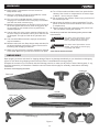 3
3
-
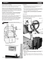 4
4
-
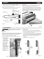 5
5
-
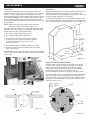 6
6
-
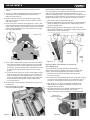 7
7
-
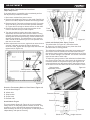 8
8
-
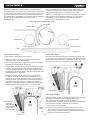 9
9
-
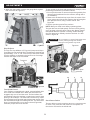 10
10
-
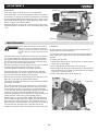 11
11
-
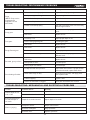 12
12
-
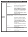 13
13
-
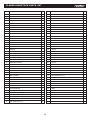 14
14
-
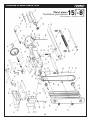 15
15
-
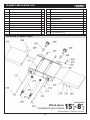 16
16
-
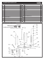 17
17
-
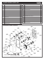 18
18
-
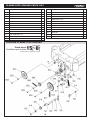 19
19
-
 20
20
-
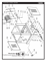 21
21
-
 22
22
-
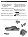 23
23
-
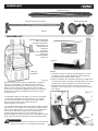 24
24
-
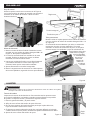 25
25
-
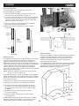 26
26
-
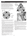 27
27
-
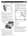 28
28
-
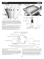 29
29
-
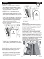 30
30
-
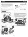 31
31
-
 32
32
-
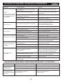 33
33
-
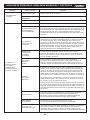 34
34
-
 35
35
-
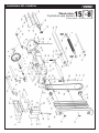 36
36
-
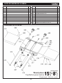 37
37
-
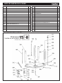 38
38
-
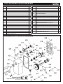 39
39
-
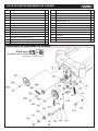 40
40
-
 41
41
-
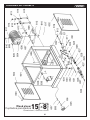 42
42
-
 43
43
-
 44
44


KNOVA KN CM-15W3 El manual del propietario
- Tipo
- El manual del propietario
en otros idiomas
- English: KNOVA KN CM-15W3 Owner's manual
Otros documentos
-
Craftsman 351.217330 El manual del propietario
-
Powermatic Planer 15HH Manual de usuario
-
-
Delta 22-790X Manual de usuario
-
-
-
Craftsman 351.217450 El manual del propietario
-
DeWalt 18657 Manual de usuario
-
-