Kenmore Elite 79032483800 Guía de instalación
- Categoría
- Cocinas
- Tipo
- Guía de instalación
Este manual también es adecuado para

iNSTALLATiON AND SERVICE MUST BE PERFORMED BY A QUALiFiED iNSTALLER.
iMPORTANT: SAVE FOR LOCAL ELECTRICAL iNSPECTOR'S USE.
READ AND SAVE THESE iNSTRUCTiONS FOR FUTURE REFERENCE.
_r_ If the information in this manual is not followed exactly, a fire or explosion may result
causing property damage, personal injury or death.
FOR YOUR SAFETY:
-- Do not store or use gasoline or other flammable vapors and liquids in
B
®
®
®
®
the vicinity of this or any other appliance.
WHAT TO DO IF YOU SMELL GAS:
Do not try to light any appliance.
Do not touch any electrical switch; do not use any phone in your building.
Immediately call your gas supplier from a neighbor's phone.
Follow the gas supplier's instructions.
If you cannot reach your gas supplier, call the fire department.
Installation and service must be performed by a qualified installer, service agency or
the gas supplier.
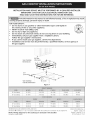
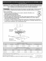
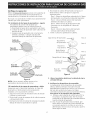
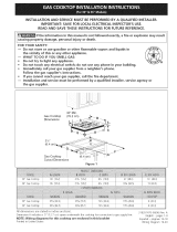
Gas Cooktop
Dimensions
21/2"
(6.4
Gas Cooktop (6.4 cm)
Cutout Dimensions ' _ ii
Figure 1
_i_i;!;i_i_i!_i_i_!_!_!_!_!_!_!_!_!_!_!_!_!_!_!_!_i_i_i!ii_i_iiiiiiiiiiiiiiiiii_i_ii_i!_ii_i!_i_i_ii_ii_ii_ii_i_i_ii_ii_ii_ii_ii_ii_ii_ii_ii_ii_ii_ii_ii_ii_ii_ii_ii_ii_ii_ii_ii_ii_ii_ii_ii_ii_ii_ii_ii_ii_ii_ii_ii_ii_ii_ii_ii_ii_ii_ii_ii_ii_ii_ii_ii_ii_ii__iiiiiiii_iiiiiiiiii_ii_iiiiiiiiiiiiiiiiiiiiiiiiiiiiiiiiiiiiiiiiiiiiiiiiiiiiiiiiiiiiiiiiiiiiiiiiiiiiiiiiiiiiiiiiiiiiiiiiiiiiiiiiiiiiiiiiiiiiiiiiiiiiiiiiiiiiiiii_i_i_i_!_i!_!_i_i_i_i_i_i_i_i_i_i_i_i_!i!_!_i_i_i_i_i_i_i_i_i_i_i_i_i_i_i_i_i_i_!_!_!_!_!_!_!_!_!_!_!_!_!_!_!_!_!_!_!_!_!_!_!_i_ii_i__!i_!i_!i_!i_!i_!i_!i_!i_!i_!i_!i_!i_!ii_ii_ii_!_ii_i_!_!_i_!!!!i!!_i!ii_ii_i_ii_ii_ii_ii_ii_ii_ii_ii_ii_i_ii_ii_i_ii_iiiiiiiiiiiiiiiiiiiiiiiiii_i_i_i_i_!i_!_i_!_!i!!_!!i!i__}_i_i@_i@_!!!!!!!!!!!!!!_!!!i!i!!_!i!i!i!_ii_i_i_i_i_i_i_i_i_i_i_i_i_i_i_i_i_i_i_i_i_i_i_i_i_i_i_i_i_i_i_i_i_i_ii_ii_i__
30"GasCooktop 30 (76.2) 213A(55.2) 4¼ (10.8) 27(68.6) 19 (48.3)
36"GasCooktop 36(91.4) 2134(55.2) 4¼(10.8) 33¼(84.5) 19(48.3)
i .................................i
30"GasCooktop 27¼(692) 28Y2(724) 191/8(486) 19_A(502) 8(20.3)
36"GasCooktop 33¼(84.5) 34¼(87) 19Y_(48.6) 19_A(50.2) 8(20.3)
All dimensions are stated in inches and (cm).
Dimension14includesa B" (12.7cm) spaceunderneaththe cooktop for connectionto gassupplyline.
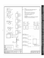
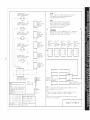
NOTE: Wiring diagrams for this cooktop are enclosed in this booklet
Printedin United States
318201479 (0806) Rev.A
English - pages 1-9
EspaBol- p_iginas 10-18
Wiring Diagram 19-20

important Notes to the Installer
1. Read all instructions contained in these installation
instructions before installing the cooktop.
2. Remove all packing material before connecting the
electrical supply to the cooktop.
3. Observe all governing codes and ordinances.
4. Be sure to leave these instructions with the consumer.
5. Note: For operation over 2000 ft. elevation above sea
level, reduce appliance rating by 4 percent, and by the
same amount for each additional 1000 ft.
important Note to the Consumer
Keep these instructions with your Use and Care Guide for
future reference.
I RTANT SAFETY
INSTRUCTION
Installation of this cooktop must conform with local
codes or, in the absence of local codes, with the National
Fuel Gas Code ANSI Z223.1/NFPA 54 in the United
States, or in Canada, with the Canadian Fuel Gas Code,
CAN/CGA B149 and CAN/CGA B149.2.
• When installed in a manufactured (mobile) home
installation must conform with the Manufactured
Home Construction and Safety Standard, title 24 CFR,
part 3280 [Formerly the Federal Standard for Mobile
Home Construction and Safety, title 24, HUD (part
280)] or, when such standard is not applicable, the
Standard for Manufactured Home Installation, ANSI/
NCSBCSA225.1 or with local codes where applicable.
This cooktop has been design certified by CSA
International. As with any appliance using gas and
generating heat, there are certain safety precautions you
should follow. You will find them in the Use and Care
Guide., read it carefully.
Be sure your cooktop is installed and grounded
properly by a qualified installer or service
technician.
This cooktop must be electrically grounded in
accordance with local codes or, in their absence,
with the National Electrical Code ANSI/NFPA No.
70--latest edition in the United States, or in
Canada, with the Canadian Electrical Code, CSA
C22.1 Part 1.
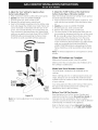
The burners can be lit manually during an
electrical power outage. To light a burner, hold a
lit match to the burner head, then slowly turn
the Surface Control knob to LITE. Use caution
when lighting burners manually.
Do not store items of interest to children in
cabinets above the cooktop. Children could be
seriously burned climbing on the cooktop to reach
items.
To eliminate the need to reach over the surface
burners, cabinet storage space above the burners
should be avoided.
Adjust surface burner flame size so it does not
extend beyond the edge of the cooking utensil.
Excessiveflame is hazardous.
Never use your cooktop for warming or heating
the room. Prolonged use of the cooktop without
adequate ventilation can be hazardous.
Do not store or use gasoline or other flammable
vapors and liquids near this or any other
appliance. Explosions or fires could result.
The electrical power to the cooktop
must be shut off while gas line connections are
being made. Failure to do so could result in serious
injury or death.

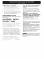
13"(33cm)
Max.Depth
ForCabinet
InstalledAbove
Cooktop.
t"
18" Min.
(45.7 cm)
11/2"(3.8 cm)Minimum Distance
Between Rear Edge of Cutout
and Nearest Combustible
Surface Above Countertop.
--It
Clearance
30" (76.2 cm)
Min. Clearance
Between the
Top of the
Cooking
Platform and
Unprotected
Wood or Metal
Cabinet
Drawers Cannot Be Used with This
Cooktop Since Burner Box Extends
3sh2" (8.02 cm) Below Surface of
_To prevent fire, or burns
when reaching over heated surfaces,
cabinet storage space located above
the cooktop should be avoided. If
cabinet storage is provided, risk can be
reduced by installing a range hood that
projects horizontally a minimum of 5"
(12.7 cm) beyond the bottom of the
cabinets.
Countertop.
C
30"C00kt0p 30"(76.2cm) 5"(12.7cm) 5"(12.7cm)
36"C00kt0p 36"(91.4cm) 5"(12.7cm) 5"(12.7cm)
Figure 2 - CABINET DESIGN
3

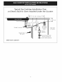
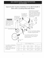
Typical Gas Cooktop Installation Over
an Electric Built-in Oven Installed Under the Counter
Wall
A__ I_l----- 18" (45.7 cm) Max.-----_
Manifold Pi
61/2"
5" .(16.5 cm)
Flare (12.7 cm) Min.
Union
Flexible Connector
Cabinet sides or
filler panel
Flare
Union
120V/6OHz
Grounded
Outlet
Pressure
Regulator
Manual Shutoff Valve
(To be accessible for
shut-off valve operation)
÷
4" (10.2 cm)
Right Side
of Cabinet
Oven Cabinet

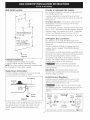
Typical
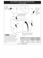
Under Counter Installation of an Electric Built-in
Oven with a Cooktop Mounted Above
All mounting hardware
must be used to secure
the built-in oven to the
cabinets. Refer to the
built-in oven installa-
tion instructions.
208/240 Volt grounded junction
box for built-in oven.
Junction box must
be located approx.
3" to the left of
the built-in oven
cutout.
This cooktop may
be installed over
certain built-in elec-
tric oven models.
Side filler panels are necessaryto
isolate the unit from adjoining
cabinets. Panel height should allow
for installation of approved cooktop
models. See "Typical GasCooktop
Installation Over an Electric Built-in
Oven Installed Under the Counter"
on previous page.
32" Min.**
(81.3 cm)
36"
(91.4 cm)
Use 3/4" (1.9 cm) plywood, installed on
two runners, flush with toe plate. Must
be capable of supporting 150 Ibs.
Cut an opening in wood base minimum 9"
(22.9 cm) x 9" (22.9 cm), 2" (5.1 cm) from
left side filler panel, to route armoured
cable to junction box.
4 1/2" (11.4 cm)
Max.*
* If no cooktop isinstalled directly
over the oven unit, 5" (12.7 cm)
maximum is allowed.
** 32" (81.3 cm) min. from top of
cabinet to top of runners must
be maintained.
CUTOUT DIMENSIONS (inches)
OVEN SIZE E F G
Min. Max. Min. Max.
30" 27Y4" 28s/8'' 28Y2" 29" 23Y2"
(76.2 cm) (69.2 cm) - (72.7 cm) (72.4 cm) - (73.7 cm) (59.7 cm)
27" 27Y4" 28s/8'' 247/8'' 25Y4" 23Y2"
(68.6 cm) (69.2 cm) - (72.7 cm) (63.1 cm) (64.1 cm) (59.7 cm)

Wall Outlet Location
: 12"q
10"
' i
|
, Recommended area for
' 120V grounded outlet
I on rear wall.
e
C_Lo_u_N_T 22"
',NOTE: If an outlet
I is not available, I
have one installed by
i a qualified technician.
r _
OF UNIT
Figure 3
Cooktop Installation
1. Visually inspect the cooktop for damage.
2. Set the cooktop into the countertop cutout.
NOTE: Do not use caulking compound; cooktop should
be removable for service when needed.
Clamp Down Information
Once the cooktop is installed in the counter opening,
/ou must clamp the unit down as shown.
Countertop
Cooktop _ /
Figure 4
To clamp down, insert an angle bracket into the slot on
each side of the unit as shown.Run thumb screw up
through the bracket, up against the bottom of the
counter. Tighten until the unit draws down and is
secure.
Provide an Adequate Gas Supply
This cooktop is designed to operate on natural gas at 4"
of manifold pressure only.
A pressure regulator is connected in series with the
manifold on the cooktop and must remain in series with
the supply line.
For proper operation, the maximum inlet pressure to
the regulator must be no more than 14" of water
column (W.C.) pressure.
For checking the regulator, the inlet pressure must be at
least 1" (or 2.5 kPa) greater than the regulator manifold
pressure setting. The regulator is set for 4" of manifold
pressure, and the inlet pressure must be at least 5".
The gas supply line to the range should be 1/2"or s4" pipe.
LP/Propane Gas Conversion
This appliance can be used with Natural gas or LP/
Propane gas. It is shipped from the factory for use with
natural gas.
A kit for converting to LPgas is supplied with your
cooktop. The kit is marked "FOR LP/PROPANEGAS
CONVERSION".
The conversion must be performed by a qualified service
technician in accordance with the kit instructions and all
local codes and requirements. Failure to follow
instructions could result in serious injury or property
damage. The qualified agency performing this work
assumes responsibility for the conversion.
Failure to make the appropriate
conversion can result in serious personal injury and
property damage.
Important: Remove all packing material and
literature from cooktop before connecting gas and
electrical supply to cooktop.
Install Pressure Regulator
Install the pressure regulator with the arrow on the
regulator pointing up toward the unit in a position
where you can reach the access cap.
Do not make the connection too tight.
The regulator is die cast. Overtightening may crack the
regulator resulting in a gas leak and possible fire or
explosion.
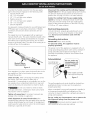
Manual GAS FLOW Pressure
Shutoff Flare _ Flare Regulator
Valve Union Union _,
On,_ t NipTpl
Nipple Flexible
Access
Off Connector
Cap
All connections must be wrench-tightened - Figure 5

Assembletheflexibleconnectorfromthegassupply
pipetothepressureregulatorinthefollowingorder:
1. manualshutoffvalve
2. 1/2"(1.3cm)nipple
3. 1/2"(1.3cm)flareunionadapter
4. flexibleconnector
5. 1/2"(1.3cm)flareunionadapter
6. 1/2"(1.3cm)nipple
7. pressureregulator
Usepipe-jointcompoundmadeforusewithNaturaland
LP/Propanegastosealallgasconnections.Ifflexible
connectorsareused,becertainconnectorsarenot
kinked.
Thesupplylinemustbeequippedwithanapproved
manualshutoffvalve.Thisvalveshouldbelocatedinthe
sameroomasthecooktopandshouldbeinalocation
thatallowseaseofopeningandclosing.Donotblock
accessto theshutoffvalve.Thevalveisforturningonor
shuttingoff gastotheappliance.
Shutoff Valve =
Open position
Figure 6
Disconnect this cooktop and its individual manual
shutoff valve from the gas supply piping system during
any pressure testing of that system at test pressures
greater than 1/2 psig (3.5 kPa or 14"water column).
Isolate the cooktop from the gas supply piping
system by closing its individual manual shutoff valve
during any pressure testing of the gas supply piping
system at test pressures equal to or less than 1/2 psig
(3.5 kPa or 14" water column).
Electrical Requirements
120 volt, 60 Hertz, properly grounded branch circuit
protected by a 15 amp circuit breaker or time delay
fuse. Do not use an extension cord with this
cooktop.
Grounding Instructions
IMPORTANT Please read carefully.
For personal safety, this appliance must be
properly grounded.
The power cord of this appliance is equipped with a 3-
prong (grounding) plug which mates with a standard 3-
prong grounding wall receptacle (see Figure 7) to
minimize the possibility of electric shock hazard from
the appliance.
Preferred Method
Grounding type
wall receptacle
not, under an,
circumstances, cut,
remove, or bypass
the grounding
prong.
Once regulator is in place, open the shutoff valve in the
gas supply line. Wait a few minutes for gas to move
through the gas line.
Check for leaks. After connecting the cooktop to the
gas supply, check the system for leaks with a
manometer. If a manometer is not available, turn on the
gas supply and use a liquid leak detector (or soap and
water) at all joints and connections to check for leaks.
Do not use a flame to check for leaks
from gas connections. Checking for leaks with a flame
may result in a fire or explosion.
Tighten all connections if necessary to prevent gas
leakage in the cooktop or supply line.
Check alignment of control knob valves after
connecting the cooktop to the gas supply to be sure the
cooktop manifold pipe has not moved. A misalignment
could cause the valve stems to rub on the control panel,
resulting in a gas leak at the valve.
Power supply cord with
3-prong grounding plug.
Figure 7
The wall receptacle and circuit should be checked by a
qualified electrician to make sure the receptacle is
properly grounded.
Where a standard 2-prong wall receptacle is installed, it
is the personal responsibility and obligation of the
consumer to have it replaced by a properly grounded 3-
prong wall receptacle.
Do not, under any circumstances, cut or remove the
third (ground) prong from the power cord.
Disconnect electrical supply cord from
wall receptacle before servicing cooktop.
7

Check Operation
RefertotheUseandCareGuidepackagedwiththe
cooktopforoperatinginstructionsandforcareand
cleaningofyourcooktop.
Donottouchtheburnersuntilyouarecertainthatthe
cooktophascompletelycooled.Theymaybehot
enoughtocauseburns.
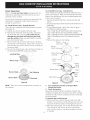
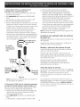
IA, InstallBurnerCaps=RegularBurners
Thiscooktopisequippedwithsealedburnersasshown
(seeFigure8).
A. Unpackyourburnerheadsandburnercaps.
B. Placeburnerheadovereachgasorifice,matching
theheadwiththeorificesize.Becarefulnotto
damagetheelectrodewhileplacingthehead
overtheorifice. Makesureelectrodefitscorrectly
intoslotinburnerhead.
C.Placeaburnercaponeachburnerhead,matching
thecapsizetotheheadsize.Eachburnercaphasan
innerlocatingringwhichcentersthecapcorrectlyon
theburnerhead.
D.Besurethatalltheburnercapsandburnerheadsare
correctlyplacedBEFOREusingyourcooktop.
IA, InstallBurnerCaps- Dual Burners
Some models are equipped with dual sealed burners as
shown (see Figure 9). Make sure that the Burner Head,
Burner Caps and Burner Skirt are installed properly and
at the correct locations.
1. Remove all packing tape from cooktop and the dual
burner.
2. Discard all packing material located under all Burners (if
applicable).
3. To install Burner Head, Caps & Skirt, refer to figure 1
and follow the following steps:
Step 1:Align Burner Head PinA on Burner BaseHole.
Step 2: PlaceBurner Skirt around Head and Base.
Step3: Align BurnerOuter CapHoleinto Burner HeadPinB.
Step 4: PlaceBurner Inner Cap centered on Burner
Base.
5. Put back the grates on the cooktop.
Burner ---_---_
Inner Cap _S
Step 4
Locating Ring
Burner Cap__ _
J
Burner Head
Gas Opening
Burner
Electrode
Cap Hole Step 3
Burner
Skirt
\\\
Head '__
Burner Burner
Head
Pin B _ _ PinA
%
Burner Head _ --- Step 2
Burner
Base
Hole
Burner
Figure 8
NOTE: There are no burner adjustments necessary on
this cooktop.
Step 1
Figure 9
2. Turn on Electrical Power and Open Main
Shutoff Gas Valve
3. Check the Igniters
Operation of electric igniters should be checked after
cooktop and supply line connectors have been carefully
checked for leaks and the cooktop has been connected
to electric power.
To operate the surface burner:
A. Push in and turn a surface burner knob to the LITE
position. You will hear a small ticking noise; this isthe
sound of the electric ignitor which lights the burner.
B. After the burner lights, turn to the desired flame size.
The controls do not have to be set at a particular
mark. Use the marks as a guide and adjust the flame
as needed.

4.Adjustthe"low" settingfor regularsurface
burnervalves(Figure10)
a. Pushinandturncontrolto LITEuntilburnerignites.
b. Quicklyturnknobto LOWESTPOSITION.
c. Ifburnergoesout,resetcontroltoOFF.
d. Removethesurfaceburnercontrolknob.
e. Insertathin-bladedscrewdriverintothehollowvalve
stemandengagetheslottedscrewinside.Flamesize
canbeincreasedordecreasedwiththeturnofthe
screw.Turncounterclockwiseto increaseflamesize.
Turnclockwisetodecreaseflamesize.Adjustflame
untilyoucanquicklyturnknobfromLITEtoLOWEST
POSITIONwithoutextinguishingtheflame.Flame
shouldbeassmallaspossiblewithoutgoingout.
Counterclockwise
Clockwise
5.Adjustthe "LOW"Settingof theDualBurner
SurfaceValve(Figure10)(somemodels):
Note:Onthedualvalvethelowsettingofeachportion
shouldbeadjustedindividually.
a. Pushinandturnknobto LITEthencontinueto turn
untilonlytheinnerportionofthedualburnerstays
on.
b. Quickly turn knob to LOWEST POSITION.
c. If burner goes out, reset control to OFF.
d. Remove the surface burner control knob.
e. The inner portion of the dual burner flame size can
be increased or decreased with the turn of the screw
B. Use screw A to adjust the low flame size of the
outer portion of the dual burner. Turn the screw
counterclockwise to increase flame size. Turn the
screw clockwise to decrease flame size. Adjust flame
until you can quickly turn knob from HIGH to
LOWEST POSITIONwithout extinguishing the flame.
Flame should be as small as possible without going
out.
Note: Air mixture adjustment is not required on surface
burners.
When All Hookups are Complete
Make sure all controls are left in the OFFposition.
Make sure the flow of combustion and ventilation air to
the cooktop is unobstructed.
Hollow
Valve
Stem
Regular
Burner
Valve
Figure 10
Note: Air mixture adjustment is not required on surface
burners.
Model and Serial Number Location
The serial plate is located on the underside of the
cooktop.
When ordering parts for or making inquires about your
range, always be sure to include the model and serial
numbers and a lot number or letter from the serial plate
of your cooktop.
Your serial plate also tells you the rating of the burners,
the type of fuel and the pressure the cooktop was
adjusted for when it left the factory.
Before You Call for Service
Read the Before You Call for Service Checklist and
operating instructions in your Use and Care Guide. It
may save you time and expense. The list includes
common occurrences that are not the result of defective
workmanship or materials in this appliance.
Refer to the back cover of your Use and Care Guide
for Sears service numbers, or call 1-800-4-MY-HOME ®.
9

LA INSTALACION Y EL SERVICIO DEBEN SER REALIZADOS POR UN INSTALADOR CAUFICADO.
IMPORTANTE: GUARDE ESTAS INSTRUCCIONES PARA USO DEL iNSPECTOR ELI_=CTRICOLOCAL.
LEA Y GUARDE ESTAS INSTRUCCIONES PARA FUTURAS REFERENCIAS
Si todas las instrucdones de este manual no son observadas a la letra, se puede
ocurrir incendios o explosiones que pueden causar daEos materiales, lesiones o la muerte.
PARA SU SEGURIDAD: f__
-- No almacene o utilice gasolina u otros vapores y liquidos inflamables cerca
de _ste o cualquier otto artefacto.
-- QUE HACER SI HAY FUGAS DE GAS :
• No intente de encender ningun artefacto
• No toque ningun interruptor el_ctrico; no utilice ningun aparato tel_fonico en su edificio.
Llame inmediatamente el abastecedor de gas desde el tel_fono de un vecino. Siga las
instrucciones del abastecedor de gas.
En caso que no puede contactar el abastecedor de gas llame al departamento de bomberos.
--La instalacion y el servicio t_l_fonico deben set realizados pot un instalador calificado, pot un
servicio tecnico certificado o pot el abastecedor de gas.
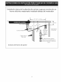
Dimensiones
de la parrilla
de cocinar
21/2"
(6.4
30" Mfn.
(76.2 cm) _- B
Dimensiones
del hueco de (6.4 cm)
, I!
la parrilla de cocinar
Figura I
M0del030" 30 (762) 213A(55.2) 4¼(10,8) 27(68.6) 19 (483)
M0del036" 36 (91,4) 213A(552) 4¼(10,8) 33¼(84,5) 19(483)
M0del030" 27¼(69,2) 28Y2(724) 19_/8(48,6) 193A(50,2) 8(20,3)
M0del036" 33¼(84.5) 34¼(87) 1978(48,6) 193A(50,2) 8(20,3)
Todas las dimensiones se dan en pulgasdas (cm).
La dimensi6n H incluye un espacio de 5" pot debajo de la plancha de cocinar para la conexi6n 318201479 (0806) Rev.A
de la linea de suministro de gas. English- pages1-9
NOTA: Se adjunta los diagramas de cables de esta plancha de cocinar con el libreta, Espahol- p_iginas10-18
Diagramade la instalaci6nal_imbrica19-20

Notas importantes para el instalador:
1. Leatodas las instrucciones de instalaciOn antes de
realizar la instalaci6n de la plancha de cocinar.
2. Retire todos los articulos de embalaje antes de realizar
lasconexiones el_ctricas a la plancha de cocinar.
3. Observe todos los c6digos o reglamentos estatales
4. Aseg0rese que el consumidor tenga estas instrucciones.
5. Nota: Para utilizar a una altitud mayor a 2000 pies pot
encima del nivel del mar, reducir el indice 4 pot ciento,
y reducir adicionalmente pot la misma cantidad cada
1000 pies.
Notas importantes para el consumidor
Guarde todas las instrucciones con su manual del usuario
para futuras referiencias.
INSTRUCCIONES DE
SEGURIDAD IMPORTANTES
La instalaci6n de esta plancha de cocinar debe realizarse
en conformidad con los c6digos locales o, si estos no
existen, con el National Fuel Gas Code ANSI Z223.1/NFPA
54 en los Estados Unidos, o en Canada, con el Canadian
Fuel Gas Code, CAN/CGA B149 y CAN/CGA B149.2.
• La instalaciOn de aparatos diseflados para instalaciOn
en casas prefabricadas (m6viles) debe conformar con el
Maufactured Home Consturction and Safet Standard,
titulo 24CFR, parte 3280 [Anteriormente el Federal
Standard for Mobil Home Construction and Safety,
titulo 24, HUD (parte 280)] o cuando tal est_qndarno se
aplica, el Standard fo Manufactured Home Installation,
ANSI/NCSBCS 225.1, o con los c6digos locales.
El diseho de esta plancha de cocinar cuenta con la
aprobaci6n de la CSA internacional. AI igual que todos
los artefactos a gas que generan calor, deben seguirse
ciertas medidas de seguridad. Vienen con el Manual del
Usuario. Lea atentamente el manual.
Asegurese que la plancha de cocinar sea instalada
y puesta a tierra correctamente por un instalador
o t_cnico calificado.
= La plancha de cocinar debe conectarse
el_ctricamente a tierra de acuerdo con los codigos
locales o, de no existir, con el codigo el_ctrico
ANSI/NFPA No. 70 = ultima edicion en los Estados
Unidos, or in Canada, con el Canadian Electrical
Code, CSA C22.1 Parte 1.
= Los quemadores pueden encenderse
manualmente durante una interruption del
suministro el_ctrico. Para encender un quemador,
mantenga un fosforo encendido en el extremo
del quemador, luego gire suavemente la perilla
hasta LITE (encendido). Tenga cuidado al
encender los quemadores en forma manual.
No deje articulos que interesan los ni_os en los
armarios que est_n sobre la la plancha de cocinar.
Les podria causar quemaduras graves si intentan
subirse para alcanzarlos.
Para eliminar el riesgo de extender pot endma de
los quemadores superiores, deberia evitar el
espacio de almacenamiento del armario,
Iocalizado por endma de estos quemadores
Gradue el tamaBo de la llama de modo que no
sobrepase el borde del utensilio de cocina,
Demasiada llama es peligrosa.
No utilice jamas la codna como calefactor. El uso
prolongado de la cocina sin la ventilaci6n adecuada
puede set peligroso.
Mantenga el area cerca de este artefacto o de
cualquier otto artefacto despejada de sustandas
combustibles, gasolina y otros liquidos
inflamables. Se puede ocurrir incendios o
explosiones.
El suministro el_ctrico a la plancha
de cocinar debe de ser cerrado durante las
conexiones a la linea. De Io contrario se puede
resultar lesiones graves o la muerte.
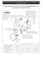
11

M_ix.profundidad
degabinetes
instaladospor
encimadela
planchade
empotares13"
(33cm).
11/2"(3.8cm)MinimoDistancia
entreelhordeposteriordel
huecoylamascercasuperficie
combustibleporencimadel
mostrador.
30"(76.2cm)
Minimode
espacioentre
T laparte
superiodela
__plataforma de
I _ laplanchade
I _ cocinaryel
' _ fondodeuna
Espacio maderanon
protegidao
armario
met_qlico.
IX B
24" C61cm_
_ ible utilisar cajones con
' esta........parr"---'---ilia de cocinar porqu_ la
caja de empalme se extiende de
3sh2" (8.02 cm) por encima de la
superficie clel mostraclor.
Para eliminar el riesgo de
alargar sobre los unidades en calentamiento
de la superficie, deberia evitarse el espacio de
almacenamiento del armario, ubicado sobre
las unidades de la superficie. Si secuenta con
este espacio, se puede disminuir el peligro
instalando una cubierta de cocina que se
extienda horizontalmente en 5" (12.7 cm)
minimo por sobre la parte inferior delantera
en los armarios.
30"C00kt0p 30"(76.2cm) 5"(12.7cm) 5"(12.7cm)
36"C00kt0p 36"(91.4cm) 5"(12.7cm) 5"(12.7cm)
Figura 2- DESENO DEL ARMARIO
12

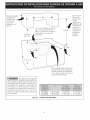
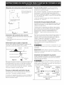
Instalacion tipica de la plancha de cocinar a gas por encima de un
homo electrico empotrado instalado debajo del mostrador
Tubo m01ti
Conector flexible
Cabinet sides or
filler panel
I I18" (45.7 cm) M_ix.-----_ I
I
61/2"
5" (13.5 cm)
(12.7 cm) Min.
UniOn
UniOn
UniOn
120V/60Hz
Toma de
corriente a
regult_l _de
presi6n
÷
4" (10.2cm)
Lado derecho
del armario
V_ilvula de cierre manual
(Debe de set accessible para el
Ifunciona-miento de la wilvula de
cierre)
Armario del horno de pared
13

Tipica instalaci6n de un horno el ctrico empotrado con una
plancha de cocinar por encima
Todas las fijaciones de
montaje deben de estar
utilizadas para sujetar el
homo empotrado a los
armarios. Refiere alas
instrucciones de
instalaci6n del homo
empotrado.
Esta plancha de cocinar puede instalarse
por encima de algunos modelos de homo
electrico empotrado.
Aproximadamente 3
(7.6 crr
Caja de empalme a tierra de
208/240 voltaje para homo
empotrado
41/2" Max.*
(11.4 cm)
Entrepaflos Ilenador de lados son
necesarios para aislar el aparato de los
armarios adyacentes. La altura de panel
debe de permitir la instalaci6n de
modelos de planchas de cocinar
aprobantes. Ver "lnstalaciOn t[pica de
plancha de cocinar a gas por encima de
un homo electrico empotrado instalado
debajo del mostrador" en la pagina 4.
32" (81.3 cm)
Minimo **
(91.4 cm)
Utilice 3/4" (1.9 cm) de madera
contrachapada, instalada sobre 2 ruedas,
perpendicular a una cima de contomo de
placa. Debe de poder sostener 150 Ibs.
Corte una abertura en la basa de
madera m[nimo 9" (22.9 cm) x 9"
(22.9 cm), 2" (5.1 cm) del entrepano
Ilenador izquierdo, para conducir el
cable blindado a la caja de empalme.
* (Si no hay plancha de cocinar
instalada directamente sobre el
aparato, un m_iximo de 5" (12.7
cm) est_Spermitido)
** Un minimo de 32" (81.3 cm)
desde la parte superior del
armario hasta la parte superior de
las ruedas debe de ser
mantenido.
DIMENSIONES DELHUECO (pulgadas)
Tamaflo E F G
del homo M[n. Max. M[n. Max.
30" 27X" 285/s '' 281/2" 29" 231/2 "
(76.2 cm) (69.2 cm) - (72.7 cm) (72.4 cm) - (73.7 cm) (59.7 cm)
27" 27¼" 28%" 24%" 25¼" 231/2"
(68.6 cm) (69.2 cm) - (72.7 cm) (63.1 cm) (64.1 cm) (59.7 cm)
14

Ubicacion de ia toma de corriente de ia pared
1 2 II
_- 8"¸¸/"_j.
Area recomendada la toma de
corriente a tierra de 120V en
Wapared posterior,
NOTA; Si no existe una toma
de corriente, contacte a un
eWectricista caWificado para
realizar la instalaci6n,
_r DpARAEToI_ 22"
I
I
/
"'_,D E L
-APARATO
Figura 3
Instalacion de la plancha de coccinar
I. Examine visualmente la plancha de cocinar para saber
si hay daho.
2. Fije el la plancha de cocinar en el recorte del
mostrador.
Inforrnaci6n para sujetar el aparato
Una vez que el aparato est,1instalado en la apertura del
mostrador, setiene que sujetar como se indica.
Cinta de Mostrador
Planchadecocinar _ esponja /
Consolade escuadra_,
Figura 4 _ _:>_"T°rn_j°sde
Para ajustar el aparato, inserte la consola de escuadra, con
el lado desviado,en las ranuras en cada lado del aparato.
El tornillo de orejas debe entonces de pasar a trav_s del
soporte y hasta la parte de abajo del mostrador. Apri_telo
hasta que el aparato se quede ajustado.
Provea un adecuado suministro de gas
Esta plancha de cocinar est,1diseflada para utilizar gas
natural de 4" de presi6n mOltiple solamente.
Se conecta un regulador de presi6n en serie al mOltiple de
la plancha de cocinar y debe permanecer en serie con la
linea de suministro de gas.
Para que manejo correcto, la presi0n de entrada
m_ixima hacia el regulador no debe exceder 14" de
presi0n de la columna de agua.
Para controlar el regulador, la presi6n de entrada debe ser
de al menos 1" (o 2.5 Kpa) mayor que el ajuste de la
presi6n del mOltiple del regulador. Elregulador seajusta
a 4" de la presi6n del mOltiple, la presi6n de entrada debe
de ser de al menos 5".
La linea de suministro de gas por el homo deberia tener
un tubo de 1/2" o de 3/4".
Conversi6n de gas propanollicuado
Esta plancha de cocinar ha sido diseflada para utilizar gas
natural o gas propano. Ha sido fijada en la f_ibrica para
utilizarse con gas natural.
Si desea hacer la conversi6n para utilizar el gas propano,
use las piezas con orificios fijados provitos en el paquete
del manual de instrucciones para la instalaci6n en el
paquete escrito "PARA LA CONVERSIONEN GAS
PROPANO". Siga las instrucciones que estan con los
orificios.
Para hacer la conversi6n del gas natural al gas propano, es
necesario utilizar el servicio de un t@cnicocalificado, in
acuerdo con las instrucciones del fabricante y todos los
c6digos y reglamentos reguladores. Sitodas las
instrucciones no son observadas, se puede ocurrir severos
lesiones o daflos materiales. La agencia calificada que
hace el trabajo asuma la responsabilidad para la
conversi6n.
Si la conversi6n apropiada no esta
observada, se puede ocurrir severos lesiones o daflos
materiales.
Importante: Retire todos los articulos de embalaje y
folletos de la cocina antes de realizar las conexiones de gas
y el@ctricasa lacocina.
15
Instalad6n del regulador de presi6n
Instale el regulador de presi6n con la fiecha del regulador
apuntando hacia la unidad en una posici6n que permita
alcanzar la tapa de entrada.
No ajuste demasiado la conexi6n. El
regular est,1fundida a presi6n. AI ajustar demasiado se
puede romper el regulador causando una fuga de gas y
un posible incendio o explosi6n.
Valvula de FLUJO DEL GAS Regulator
_41_ de presi6n
cierre Uni6n Uni6n
manual
, t
Abierto € 1_ t Boq_illa_
(on) _ Boquilla Conector
Apagado flexible Tapa de
(off) entrada
Todas las conexiones deben ajustarse con
una Ilave de tuerca
Figura 5

Monteelconectorflexibledeltubodelsuministrodegas
alreguladordepresiOnenfuncionamiento:
1.v_lvuladecierremanual
2. boquillade1/2"(1.3cm)
3. adaptorde1/2"(1.3cm)
4. conectorflexible
5. adaptatorde1/2"(1.3cm)
6. boquillade1/2"(1.3cm)
7. reguladordepresiOn.
Utiliceuncompuestodetuboarticuladoparausodegas
naturalypropanoparasellartodaslasconexionesdegas.
Siseutilizanconectoresflexibles,aseg0resequelos
conectoresnoest_intorcidos.
Eltubodesuministrodegasdebreri_incluirunav_lvula
decierrecertificada.Estav_lvuladeberi_estarubicadaen
lamismahabitaci61ndelaplanchadeconinarydeberi_
estarenunlugarquepermitaunaaberturaycierre
f_ciles.Nobloqueelasentradasdelav_lvuladecierre.La
v_lvulasirveparaabriro cerrarelpasodelgasal
artefacto.
AI
Valvula de cierre =
Abierta
Figura 6
Abra la v_lvula de cierre en el tubo de suministro de gas.
Espere unos minutos para que el gas pase a trav_s del
tubo de gas.
Verifique si hay fugas. Luego de conectar la cocina al
gas, verifique el sistema con un man0metro. Si no cuenta
con _ste instrumento, d_ la vuelta al suministro de gas de
la cocina y utilice un detector de fugas liquidas (o agua y
jabOn) en todas las articulaciones y conexiones para
verificar si existen fugas.
No use ningOn tipo de llama para
verificar si hay fugas de gas. Verifique si hay fugas con
una llama puede occasionar incendio o explosion.
Ajuste todas las conexiones en caso que sea necesario,
para evitar fugas de gas en la cocina o en el tubo de
sumininistro de gas.
Verifique la alineadOn de las v_lvulas luego de
conectar la plancha de cocinar al suministro de gas para
asegurar que no se ha movido la %lvula del mOltiple de la
plancha de cocinar.
Desconecte la codna y su v_lvula de derre individual
del sistema de tuberia del suministro de gas durante
cualquier ensayo de presiOn del sistema en ensayos de
presiOn superiores a 1/2 psig (3.5 kPa o 14" colomna de
agua).
Aparte la codna del sistema de tuberia del suministro
de gas cierrando su v_lvula de cierre individual manual,
durante cualquier ensayo de presiOndel systema de
suministro de gas en ensayos iguales o inferiores a 1/2 psig
(3.5 kPao 14" colomna de agua).
Requedmientos electricos:
Un circuito derivado conectado correctamente a tierra de
120 voltios, 60 Herz protegido por un interruptor
autom_itico de 15 amp o un fusible de retardo. No utilice
un cable flexible de extension en esta plancha de
codnar.
Instrucdones para ia puesta a tierra
IMPORTANTE Por favor, lea atentamente.
Como medida de seguridad personal, est_ artefacto
debe conectarse a tierra correctamente.
El cable de encendido de este artefacto incluye un
enchufe de tres patas (a tierra) que calza con un enchufe
de pared de tres patas de conexiOn a tierra (ver Figura 7)
para disminuir la posibilidad de peligro de choques
el_ctricos desde el artefacto.
M _:TODO PREFERIDO
baio
Enchure de
pared a tierra
encendido.
Cablo de encendido
con enchufe de tres
patas a tierra
Figura 7
Un electricista calificado debe verificar el enchufe de pared
y el circuito para asegurar que el enchufe est,1conectado a
tierra correctamente.
En caso de encontrarse con un enchufe de pared de dos
patas, es la personal responsibilidad y la obligaciOn del
consumidor reemplazarlo por el enchufe de pared a tierra
de tres patas correspondiente.
No debe, bajo ninguna circunstancia cortar o retirar
la tercera pata (tierra) del cable de encendido
Desconecte el cable del suministro
el_ctrico del enchufe de pared antes de reparar la
plancha de cocinar.
16

Verifique ia operacion
Refiera al Manual del Usuario que viene con la plancha de
cocinar para las instrucciones de funcionamiento y el
mantenimiento y la limpieza de su plancha de cocinar.
No toque a los quemadores. Pueden estar suficientemente
calientes par causar quemaduras.
IA. Instalaci6n de las tapas de quemadores - regular
Esta plancha de cocinar est,1equipada con
quemadores sellados como se muestra (Figura 8)
A. Desembale las tapas de los quemadores y las bases.
B. Coloque las basas de quemador sobre cada tubo de
abertura de gas.
C. AsegOrese que el quemador est,1correctamente
alineado y nivelado. Coloque cada tapa del
quemador debajo de cada base del quemador.
Anillo de
localizadOn
Tapa del J
/
quemadore /
1
_- i \\
Base del
quemadore
Anillo del
quemadore
Abertura
gas
Electrodo
4. Para instalar la cabeza del Quemador, las Tapasy el
Borde exterior, referir a la figura 9 y seguir los
siguientes pasos:
Paso 1: Alinear la clavija A que sobresale de la Cabeza
del Quemador con el hoyo de la Basedel Quemador.
Paso 2: Colocar el Borde exterior del Quemador
alrededor de la Base y la Cabeza.
Paso 3: Alinear el hoyo de la Tapa Externa del
Quemador con la clavija B de la Cabeza del
Quemador.
Paso4: Colocar la Tapa Interna del Quemado
centrada sobre la Basedel Quemador.
5. Volver a colocar las parrillas de la cubierta.
Tapa Interna del Quemador
Tapa Externa
del Quemador
Hoyo de la
Tapa Externa
Borde Exterior
del Q
Clavija A de la Cabeza
Cabeza del
Quemador
Base del
Quemador
Paso4
Paso3
Paso2
Clavija B
de la
Cabeza
Paso1
Hoyo de
la Base
Figura 9
Figura 8
NOTA: No es necesario realizar ajustes en los
quemadores de esta plancha de cocinar.
lB. InstaladOn de las tapas de quemadores =doble
Asegurarse que la Cabeza del Quemador, las Tapas del
Quemaclor y el borde exterior est_n propiamente
instalados yen sus posiciones correctas.
1. Seguir las instrucciones de instalaciOn antes de instalar
y utilizar su nueva estufa.
2. Quitar toda la cinta de empaque de la cubierta superior
y del quemador triple.
3. Deshacerse de todo el material de empaque Iocalizaclo
debajo de todos los Quemadores (siaplica).
2. Abre el suministro electrico y la v<ilvula de cierre
principal del gas.
,
Verifique los dispositivos de encendido
La manipulaci6n de los dispositivos de encendido
ekctrico deberfa verificarse tras haber revisado
detenidamente la plancha de cocinar y los conectores
del tubo del suministro de fugas y tras haber
conectado la plancha de cocinar al suministro ekctrico.
Para operar en la superficie del quemador:
A. Presione y gire la perilla de control hasta LITE.Se
escuchar_i a un pequeflo ruido. Estees el ruido
producido por el dispositivo de encendido ekctrico
cuando enciende el quemador.
B. Una vez que el quemador est,1encendido, gire
hasta obtener el tamaflo de la llama deseada. No
es necesario ajustar los controles en una marca
determinada. Use las marcas como gufa y ajuste la
llama segOn se desea.
17

4.Ajustebajo("LO")aralav,ilvuladelos
quemadoresdesuperficie(Figura9)
a.PresioneygireelcontrolhastalaposiciOnLITEpara
prenderlosquemadores.
b.Girer_pidamentegirelaperillaalaPOSICIONMAS
BAJA.
c.Sielquemadorseapaga,reajusteelcontrolaOFE
d.Retirelaperilladelquemadordesuperficie.
e.Inserteundestornilladorfino-aplanadoenelorificodel
wistagodelawilvulaeinserteeneltornilloranurado.
Eltamahodelallamapuedeaumentarseodisminuirse
d_indolevueltaal tornillo.D_vueltaensentido
opuestoalasmanecillasdelrelojparaaumentarel
tamahodelallama.D_vueltaensentidoalas
manecillasdelrelojparadisminuirlallama.Ajustela
llamahastaqueustedpuededarvueltar@idamentea
laperilladelaposici6nLITEalaPOSICIONMASBAJA
sinextinguirlallama.Lallamadebesettanpequeha
comoseaposiblesinapagarse.
Ensentidodelas
manecillasdel
_i_ rel°j
Ensentido
opuestoalas
manecillasdel
reloj
Elhuecodel
v&stagode
lav&lvula
d. Retirelaperilladelquemadordesuperficie.
e. Eltamahodelaflamadelaporci6ninteriordel
quemadordoblepuedeaumentarseodisminuirse
d_indolevueltaaltornilloB.UtiliceeltornilloApara
ajustareltamahodelallamadelaposicionLOWdela
porci6nexteriordelquemadordoble.D_vueltaen
sentidoopuestodelasmanecillasdelrelojpara
aumentareltamahodelallama.D_vueltaensentido
alasmanecillasdelrelojparadisminuirlallama.Ajuste
lallamahastaqueustedpuededarvueltar@idamente
alaperilladelaposici6nHIGHalaPOSICIONMAS
BAJAsinextinguirlallama.Lallamadebesettan
pequehacomoseaposiblesinapagarse.
Nota:Elajustedelamezcladelairenoserequiereenlos
quemadoresdesuperficie.
Cuando se ban realizado todos los sistemas
de conexi on
Aseg0rese que todos los controlos est_in en la posiciOn de
OFF(apagado).
AsegOrese que el flujo de combusti 6n y ventilaci6n de
aire de la cocina no est_in obstruidos
Modelo y ubicad6n del numero de serie
La placa de n0mero de serie est,1ubicada en el lado de
abajo de la caja de quemadores.
Aseg0rese de incluir el modelo, n0mero de serie y el
n0mero o letra del Iote que se encuentran en la placa, en
todo pedido de partes o solicitud de informaci6n acerca
de su plancha de cocinar.
La placa de nOmero de serie tambi@n indica las
especificaciones de los quemadores, el tipo de
combustible y la presi6n para la cual fu@ajustada la
plancha de cocinar en la f_ibrica.
V_ilvula de
superficie de
quemador wilvula del
regular quemador
Puente
Figura 9
Nota: El ajuste de la mezcla del aire no se requiere en
los quemadores de superficie
5. Ajuste bajo "LOW" para la v,ilvula de quemador
de superficie doble (algunos modelos) (Figura 9)
Nota: En la wilvula de quemador done el ajuste <<LOW>>
de cada porci6n se debe ajustar individualmente.
a. Presione y gire la perilla a la posici6n LITEluego, siga
girendo hasta que usted vea solamente la flama
interna del quemador doble.
b. Gire rapidamente a la perilla a la POSICION MAS
BAJA.
c. Si el quemador se apaga, reajuste el control a OFE
Antes de ilamar ai servicio
Lea la secciOn Lista de Control de Averias en su Manual
del Usuario. Esto le podr_i ahorrar tiempo y gastos. Esta
lista incluye ocurrencias comunes que no son el
resultado de defectos de materiales o fabricaci6n de
este artefacto.
Lea la garantia y la informaci6n sobre el servicio en su
Manual del Usuario para obtener el nOmero de tel_fono
y la dirreciOn del servicio o Ilamar 1-888-SU-HOGAR sM.
Por favor Ilame o escriba si tiene preguntas acerca de su
estufa o necesita repuestos.
18

LO
TOP BURNER IGNITER
OPTIONAL
GUEMADOR DE ENCENDIDO SUPERIOR
OPCIONAL
BOOGIE D'ALLUMAGE-BRULEUR
TOP BURNER IGNITER
OPTIONAL
QUEMADOR DE ENCENDIDO SUPERIOR
OPCIONAL
BOUGIE D'ALLUMAGB-BRULEUR
TOP BURNER IGNITER
QUENADOR DE ENCENOIDO SUPERIOR
BOUGIE D'ALLUMAGE-BRULEUR
IGNITER MODULE BOARD
CUADRO DE MODULO DE ENCENDIDO
GROUND
PUESTA
MISE A
WARNING
DIRECT POWER BEFORE SERVICING UNIT,
AVISO
DE_NECTE LA ENERGIA ANTES DE REALIZAR
EL MANTENIMIENTO DEL ELECTRODOMESTIDO.
AVERTISSEMENT
COUPER LE COURANT AVANT D'EFFECTUER LA
REPARATION.
_OLOR CODE / CODIGOS DE COLOR / CODE COULEUR
3K BLACK / NEGRO / NOIR
WHITE / BLANCO / BLANC
2 18 200 3304
1 20 150 3321
WIRE GAGE UL STYLE
ALAMBRE MEDIDA TEMpOC MODO UL
FIL CAL, STYLE UL
L1
CAUTION:
LABEL ALL WIRES PRIOR TO DISCONNECTION WHEN SERVICING CONTROLS,
WIRING ERROR CAN CAUSE IMPROPER AND DANGEROUS OPERATION.
VERIFY PROPER OPERATION AFTER SERVICING,
AVlSO:
ETIQUETE TODOS LOS ALAMBRES ANTES DE DESCONECTAR PAR
REALIZAR ET MANTENIMIENTO DE LOS CONTROLES,ERROR DE
ALAMBRAJE PUEDE CAUSAR UN FUNCIONAMIENTO INCORRECTO
Y PELIGROSO.VERIQUE SI EL FUNCIONAMIENTO ESTA
CORRECTO DESPUES DEL MANTENIMIENTO,
AVERTISSEMENT:
ETIQUETER CMAQUE FIL AVANT LE DEBRANCHEMENT DE CEUX-CI.UNE ERRBUR DE
BRANCHEMENT PEUT CAUSER UNE OPERATION DANGEREUSE,VERIFIER LE BON
FONCTIONNEMENT DE L'APPAREIL APRES TOUTE REPARATION*
RIGHT FRONT LEFT FRONT
IGN.SW. IGN,SW,
tNT.ENC, DE INT*ENC, DE
FRENTE DERECHO FRENTE IZQUIERDO
INTER.ALLUM, INTER,ALLUM,
D,AV, G,AV,
TOP BURNER IGNITER
QUEMADOR DE ENCENDIDO SUPERIOR
BOUGtE D'ALLUMAGB-BRULEUR
TOP BURNER IGNITER
GUEMADOR DE ENCBNDIDO SUPERIOR
BOUGIE D'ALLDMAGE-BRULEUR
TOP BURNER IGNITER
QUEMADOR DE ENCENDIDO SUPERIOR
BOUGIE D'ALLUMAGE-BRULEUR
TOP BURNER IGNITER
QUEMADOR DE ENCENOIDO SUPERIOR
BOUGIE D'ALLUMAGE_BRULEUR
'_ O0 LO
,_ oo
LEFT REAR RIGHT REAR
IGN.SW, IGN.SW*
INT,ENC,TRASERO INT.ENC.TRASERO
IZQUIERDO DERECHO
INTER,ALLUM, INTER_ALLUM_
G.AR, D,AR,
N
3180471 16 REV.A
NO
IGNITER MODULE BOARD
CUADRO DE MODULO DE ENCENDIDO
BLOC CONNECTION ALLUMEUR

IX,j
O
TOP BURNER IGNITER
QUEMADOR DE ENCENDIDO SUPERIOR
BOUG I E D' ALLUMAGE BRULEUR
TOP BURNER IGNITER
OUEMADOR DE ENCENDIDO SUPERIOR
BOUGIE D'ALLUMAGE BRULEUR
TOP BURNER IGNITER
OUEMADOR DE ENCEND IDO SUPERI OR
BOUG [ E D" ALLUMAGE BRULEUR
I
i
TOP BURNER ]GNI TEA
OUEMADQR DE ENCEND IDO SUPERI OR
BOUGI E D" ALLU,_:AGE BRULEUR
TOP BURNER IGNITER
OUEMADOR DE ENCENOIDO SUPERIOR
BOUG[E D'ALLUMAGE BRULEUR
IGNITER MODULE BOARD
CUADRO DE MODULO DE ENCENDIDO
BLOC CONNECTION ALLUMEUR
WARNING
DISCONNECT POWER BEFORE SERVICING UNIT.
AVISO
DESCONECTE LA ENERGIA ANTES DE REALIZAR
EL MANTENIMIENTO DEL ELECTRODOMESTICO.
DISCONNECT POWER BEFORE SERVICING UNIT.
AVERTISSEMENT
COUPER LE COuRANT AVANT O'EFFECTUER LA
REPARATION.
GROUND
PUESTA A TIERRA
MISE A LA TERRE
RIGHT REAR
IGN. SW.
INT. ENC. TRASERO
DERECHO
INTER. ALLUH.
D. AR.
LEFT REAR
IGN. BW.
]NT ENC TRABERO
IZQU[ERDO
INTER. ALLUM.
G. AR.
LEFT FRONT
iGN. SW.
iNT. ENC. DE
YRENTE IZOUIERDO
INTER. ALLUM.
G. AV.
RIGHT FRONT
[GN. SW.
[NT. ENC. DE
FRENTE DERECHO
INTER. ALLUM.
D. AV.
CENTRE REAR
]GN. SW.
]NT ENC CENTRO
TRASERO
]NTER. ALLUM.
C. AR.
R 4
CONNECTOR
EMPALME
CONNECTEUR
POWER CORD
PARA TRANSPORTE
DE FUERZA
CABLE
D'ALIMENTATION
L1
CAUTION:
LABEL ALL WIRES PRIOR TO DISCONNECTION WHEN SERVICING CONTROLS.
WIRING ERROR CAN CAUSE IMPROPER AND DANGEROUS OPERATION
VERIFY PROPER OPERATION AFTER SERVICING.
AVlSO:
ETIOUETE TOOOS LOS ALAMBRES ANTES DE OESCONECTAR PAR
REALIZAR ET MANTENIMIENTO DE LOS CONTROLES. ERROR DE
ALAMBRAJE PUEDE CAUSAR UN FUNCIONAMIENTO INCORRECTO
v PELIGROSO. VERIOUE S] EL FUNC[DNAMIENTD ESTA
CORRECTO DESPUES DEL MANTENIMIENTO.
AVERTIb-'SEi'_NT:
ETIOUETER CHAOUE F[L AVANT LE DEBRANCHEMENT DE CEUX CI.UNE ERREUR DE
BRANCHEMENT PEUT CAUSER UNE OPERATION DANGEREUSE. VERIF]ER LE BON
FONCTiONNEMENT DE L'APPAREIL APRES TOUTE REPARATION.
N
CENTRE REAR RIGHT FRONT LEFT FRONT LEFT REAR RIGHT REAR
IGN. SW. IGN. SW. IGN. SW. IGN. SW. IGN. SW.
INT. ENC. CENTRO INT. ENC. DE INT. ENC. DE INT. ENC. TRASERO INT. ENC.TRASERO
TRASERO FRENTE DERECHO FRENTE ]ZOUIERDO IZOUIERDO DERECHO
INTERALLUM. INTER. ALLUM. INTER. ALLUM. INTER.ALLUM. INTER. ALLUM.
C. AR. D AV. G. AV. G. AR. D. AR.
.CJ
TOP BbRNER IGNITER
QUE'_IADDR DE ENCEND I DO SUPER I OR _j
BOUG]E O" ALLUMAGE BRULEUR
.J
NOTE :
m
I
O _ () L ,9--
! I IGNITER MODULE BOARD
CUADRO DE MODULO DE ENCENDIDO
BLOC CONNECTION ALLUMEUR
SERVICE:IF REPLACEMENT OF TERMINALS BECOMES NECESSARY, COMPARABLE WIRE TYPE AND
GAGE AND COMPARABLE TERMINALS MUST BE USED.
NOTA:
EN CASO QUE SEA NECESARIO DE REEMPLAZAR LOS BORNES. ES NECESARIO DE UTILIZAR
EL MISMO TIPO DE ALAMBRE Y DE MEDIDOR Y EL MISMO TIPO DE BORNES.
NOTE:
SERVICE:S] DES FILS OU DES COSSES DOIVENT ETRE REMPLACES, UTILISEZ DES °IECEB
DE CALIBRE ET DE TYPES EQUIVALENTS.
,3180471 12 REV. A
-
 1
1
-
 2
2
-
 3
3
-
 4
4
-
 5
5
-
 6
6
-
 7
7
-
 8
8
-
 9
9
-
 10
10
-
 11
11
-
 12
12
-
 13
13
-
 14
14
-
 15
15
-
 16
16
-
 17
17
-
 18
18
-
 19
19
-
 20
20


Kenmore Elite 79032483800 Guía de instalación
- Categoría
- Cocinas
- Tipo
- Guía de instalación
- Este manual también es adecuado para
en otros idiomas
Artículos relacionados
Otros documentos
-
Electrolux 36 Manual de usuario
-
Electrolux EW30GC55G Manual de usuario
-
Frigidaire FFGC3015LSB Guía de instalación
-
Electrolux EW36GC55GW2 Guía de instalación
-
-
Kenmore 79032413901 Guía de instalación
-
Electrolux ECCG3068AS Guía de instalación
-
Kenmore Pro Pro 36'' Gas Drop In Cooktop Guía de instalación
-
Kenmore 79032429903 Guía de instalación
-
Electrolux EW36GC55GW2 Guía de instalación