
iNSTALLATiON AND SERVICE MUST BE PERFORMED BY A QUALiFiED iNSTALLER.
iMPORTANT: SAVE FOR LOCAL ELECTRICAL iNSPECTOR'S USE.
READ AND SAVE THESE iNSTRUCTiONS FOR FUTURE REFERENCE.
If the information in this manual is not followed exactly, a fire or explosion may result
causing property damage, personal injury or death.
FOR YOUR SAFETY:
-- Do not store or use gasoline or other flammable vapors and liquids in
0
0
0
0
m
the vicinity of this or any other appliance.
WHAT TO DO IF YOU SMELL GAS:
Do not try to light any appliance.
Do not touch any electrical switch; do not use any phone in your building.
Immediately call your gas supplier from a neighbor's phone.
Follow the gas supplier's instructions.
If you cannot reach your gas supplier, call the fire department.
Installation and service must be performed by a qualified installer, service agency or
the gas supplier.
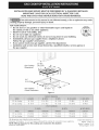
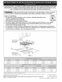
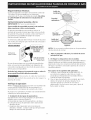
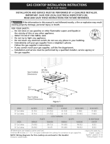
Gas Cooktop
Dimensions
21/2"
30" Min.
(76.2 cm) _la
Gas Cooktop (6.4 cm)
Cutout Dimensions , tt
Figure 1
i_!_iiii__i_i_i_!iii!_i_i_¸i_i_i!_!_!_i_i_i_i_i_i_!ii_!!!!!_i_i_i_i_i_i_i_i_i_i_i_i_i_!_!_!_!_!!!!_ii_
30"GasCooktop 30 (76.2) 213A(55.2) 4_A(10.8) 27(68.6) 19 (48.3)
36"GasCooktop 36 (91.4) 213A(55.2) 4_A(10.8) 33_/4(84.5) 19(48.3)
u
30"GasCooktop 27Y4(69.2) 273A(70.5) 19_/8(48.6) 19s/8(49.8) 8 (20.3)
36"GasCooktop 33_/4(84.5) 333A(85.7) 19_/8(48.6) 19s/8(49.8) 8 (20.3)
All dimensions are stated in inches and (cm).
Dimension H includes a 5" (12.7 cm) space underneath the cooktop for connection to gas supply line.
NOTE: Wiring diagrams for this cooktop are enclosed in this booklet
Printed in United States
318201470 (0606) Rev.A
English - pages 1-9
Espar_ol- p_qginas10-18
Wiring Diagram 19-20

Important Notes to the Installer
I. Read all instructions contained in these installation
instructions before installing the cooktop.
2. Remove all packing material before connecting the
electrical supply to the cooktop.
3. Observe all governing codes and ordinances.
4. Be sure to leavethese instructions with the consumer.
5. Note: For operation at 2000 ft. elevations above see
level, appliance rating shall be reduced by 4 percent
for each additional 1000 ft.
Important Note to the Consumer
Keep these instructions with your Useand Care Guide for
future reference.
IMPORTANT SAFETY
INSTRUCTIONS
Installation of this cooktop must conform with local codes
or, in the absence of local codes, with the National Fuel
Gas Code ANSI Z223.1/NFPA 54 in the United States, or
in Canada, with the Canadian Fuel Gas Code, CAN/CGA
B149 and CAN/CGA B149.2.
When installed in a manufactured (mobile) home
installation must conform with the Manufactured Home
Construction and Safety Standard, title 24 CFR,part
3280 [Formerly the Federal Standard for Mobile Home
Construction and Safety, title 24, HUD (part 280)] or,
when such standard is not applicable, the Standard for
Manufactured Home Installation, ANSI/NCSBCS A225.1
or with local codes where applicable.
This cooktop has been design certified by CSA
International. As with any appliance using gas and
generating heat, there are certain safety precautions you
should follow. You will find them in the Use and Care
Guide, read it carefully.
• Be sure your cooktop is instaJJed and grounded
properly by a qualified installer or service
technician.
This cooktop must be electrically grounded in
accordance with local codes or, in their absence,
with the National ElectricaJ Code ANSI/NFPA No.
70--latest edition in the United States, or in
Canada, with the Canadian Electrical Code, CSA
C22.1 Part 1.
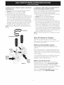
• The burners can be lit manually during an
electrical power outage. To light a burner, hold a
lit match to the burner head, then slowly turn the
Surface Control knob to MTE. Use caution when
lighting burners manually.
• Do not store items of interest to children in
cabinets above the cooktop. Children could be
seriously burned climbing on the cooktop to reach
items.
• To eliminate the need to reach over the surface
burners, cabinet storage space above the burners
should be avoided.
• Adjust surface burner flame size so it does not
extend beyond the edge of the cooking utensil
Excessive flame is hazardous.
• Never use your cooktop for warming or heating
the room. Prolonged use of the cooktop without
adequate ventilation can be hazardous.
• Do not store or use gasoline or other flammable
vapors and liquids near this or any other
appliance. Explosions or fires could result.
The electrical power to the cooktop
must be shut off while gas line connections are
being made. FaiJure to do so could resuJt in serious
injury or death.

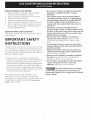
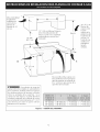
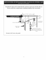
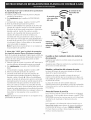
13" (33 cm)
Max. Depth
For Cabinet
Installed Above
Cooktop.
18" Min,
(45.7 cm)
I
11/2"(3.8 cm)Minimum Distance
Between RearEdge of Cutout
and Nearest Combustible Surface
Above Countertop,
Clearance
30" (76.2 cm)
Min, Clearance
Between the
Top of the
Cooking
Platform and
Unprotected
Wood or Metal
Cabinet
B
k
24" cm)
\
_To eliminate the risk of
burns or fire from reaching over heated
surfaces, cabinet storage space located
above the cooktop should be avoided. If
cabinet storage is provided, risk can be
reduced by installing a range hood that
projects horizontally a minimum of 5"
(12.7 cm) beyond the bottom of the
cabinets.
Drawers Cannot Be Used with This
Cooktop Since Burner Box Extends
3s/32'' (8.02 cm) Below Surface of
Countertop.
30'_Cooktop 30'_(76.2 cm) 7'_(17.8 cm)
36'_Cooktop 36'_(91.4 cm) 7'_(17.8 cm)
7"(17.8 cm)
7"(17.8 cm)
Figure 2 - CABINET DESIGN

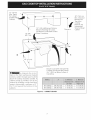
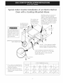
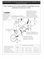
Typical Gas Cooktop Installation Over
an Electric Built-in Oven Installed Under the Counter
Wall
Manifold Pi
Flexible Connector
Oven Cabinet
I_---- 18" (45.7 cm) Max.-----_
J
Cabinet sidesor
filler panel
61_2"
5" ,(16.5 cm)
Flare (12.7cm) Min.
Union
_J Flare
_j Union
120V/60Hz
Grounded
Outlet
Pressure
Regulator
4" (10.2 cm)
Right Side of
Cabinet
Manual Shutoff Valve
(To be accessible for
shut-off valve opera-
tion)

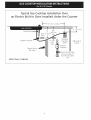
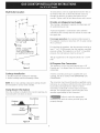
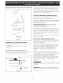
Typical Under Counter Installation of an Electric Built-in
Oven with a Cooktop Mounted Above
All mounting hardware
must be used to secure
the built-in oven to the
cabinets. Refer to the
built-in oven installa-
tion instructions.
Junction box must
be located approx.
3" to the left of
the built-in oven
cutout,
208/240 Volt grounded junction
box for built-in
This cooktop may
be installed over
certain built-in elec-
tric oven models.
Side filler panels are necessary to
isolate the unit from adjoining
cabinets. Panel height should allow
for installation of approved cooktop
models. See "Typical Gas Cooktop
Installation Over an ElectricBuilt-in
Oven Installed Under the Counter"
on previous page.
32" Min.**
(81.3 cm)
36"
(91.4 cm)
Use 3/4" (1.9 cm) plywood, installed
on two runners, flush with toe plate.
Must be capable of supporting 150 Ibs.
Cut an opening in wood base minimum 9"
(22.9 cm) x 9" (22.9 cm), 2" (5.1 cm) from
left side filler panel, to route armoured
cable to junction box.
4 1/2" (11.4 cm)
Max.*
* If no cooktop is installed directly
over the oven unit, 5" (12.7 cm)
maximum is allowed.
** 32" (81.3 cm) min. from top of
cabinet to top of runners must be
maintained.
CUTOUT DIMENSIONS (inches)
OVEN SIZE E F G
Min. Max, Min. Max.
30" 27¼" 28s/8 '' 281/2" 29" 231/2"
(76.2 cm) (69.2 cm) - (72.7 cm) (72.4cm) - (73.7 cm) (59.7 cm)
27" 27¼" 28s/8 '' 247/8 '' 25¼" 231/2"
(68.6cm) (69.2cm) - (72.7cm) (63.1cm) (64.1cm) (59.7cm)

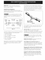
Wall Outlet Location
12"_
10"
Recommended area for
12OV grounded outlet
on rear wall.
_.._F UEN_T 22"
: NOTE: If an outlet
I is not available,
have one installed by
i a qualified technician. _,
OF UNIT
Figure 3
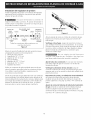
Cooktop Installation
1. Visually inspect the cooktop for damage.
2. Set the cooktop into the countertop cutout.
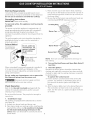
To clamp down, insert an angle bracket into the slot on
each side of the unit as shown.Run thumb screw up
through the bracket, up against the bottom of the
counter. Tighten until the unit draws down and issecure.
Provide an Adequate Gas Supply
This cooktop isdesigned to operate on natural gas at 4"
of manifold pressure only.
A pressure regulator is connected in series with the
manifold on the cooktop and must remain in series with
the supply line.
For proper operation, the maximum inlet pressure to
the regulator must be no more than 14" of water column
(W.C.) pressure.
For checking the regulator, the inlet pressure must be at
least 1" (or 2.5 kPa) greater than the regulator manifold
pressure setting. The regulator is set for 4" of manifold
pressure, the inlet pressure must be at least 5".
The gas supply line to the range should be I/2" or 3/4"
pipe.
LP/Propane Gas Conversion
This appliance can be used with Natural gas or LP/
Propane gas. It is shipped from the factory for use with
natural gas.
A kit for converting to LPgas is supplied with your
cooktop. The kit is marked "FOR LP/PROPANEGAS
CONVERSION".
NOTE: Do not use caulking compound; cooktop should
be removable for service when needed.
Clamp Down Information
Once the cooktop is installed in the counter opening, you
must clamp the unit down as shown.
Countertop
Cooktop _ t
, _ _ ,
Angle ......__Ll_
Bracket_
_ Thumb
Screw
Figure 4
The conversion must be performed by a qualified service
technician in accordance with the kit instructions and all
local codes and requirements. Failure to follow
instructions could result in serious injury or property
damage. The qualified agency performing this work
assumes responsibility for the conversion.
Failure to make the appropriate
conversion can result in serious personal injury and
property damage.

Important: Removeallpackingmaterialand
literaturefromcooktopbeforeconnectinggasand
electricalsupplytocooktop.
Install Pressure Regulator
Install the pressure regulator with the arrow on the
regulator pointing up toward the unit in a position where
you can reach the access cap.
Do not make the connection too tight.
The regulator is die cast. Overtightening may crack the
regulator resulting in a gas leak and possible fire or
explosion.
Manual GAS FLOW Pressure
Shutoff Flare _'_ Flare Regulator
Valve Union Union _,
÷
Nipple Flexible Access
Off Connector
Cap
All connections must be wrench-tightened
Figure 5
Assemble the flexible connector from the gas supply pipe
to the pressure regulator in the following order:
I. manual shutoff valve
2. I/2" (1.3 cm) nipple
3. 1/2" (1.3 cm) flare union adapter
4. flexible connector
5. I/2" (1.3 cm) flare union adapter
6. 1/2" (1.3 cm) nipple
7. pressure regulator
Use pipe-joint compound made for use with Natural and
LP/Propane gas to seal all gas connections. If flexible
connectors are used, be certain connectors are not
kinked.
The supply line must be equipped with an approved
manual shutoff valve. This valve should be located in the
same room as the cooktop and should be in a location
that allows ease of opening and closing. Do not block
access to the shutoff valve. The valve is for turning on or
shutting off gas to the appliance.
Shutoff Valve =
Open position
Figure 6
Once regulator is in place, open the shutoff valve in the
gas supply line. Wait a few minutes for gas to move
through the gas line.
Check for leaks. After connecting the cooktop to the
gas supply, check the system for leaks with a
manometer. If a manometer is not available, turn on the
gas supply and use a liquid leak detector (or soap and
water) at all joints and connections to check for leaks.
Do not use a flame to check for leaks
from gas connections. Checking for leaks with a flame
may result in a fire or explosion.
Tighten all connections if necessary to prevent gas
leakage in the cooktop or supply line.
Check alignment of control knob valves after
connecting the cooktop to the gas supply to be sure the
cooktop manifold pipe has not moved. A misalignment
could cause the valve stems to rub on the control panel,
resulting in a gas leak at the valve.
Disconnect this cooktop and its individual manual
shutoff valve from the gas supply piping system during
any pressure testing of that system at test pressures
greater than I/2 psig (3.5 kPa or 14"water column).
Isolate the cooktop from the gas supply piping
system by closing its individual manual shutoff valve
during any pressure testing of the gas supply piping
system at test pressures equal to or less than I/2 psig
(3.5 kPa or 14" water column).

Electrical Requirements
120 volt, 60 Hertz, properly grounded branch circuit
protected by a 15 amp circuit breaker or time delay fuse.
Do not use an extension cord with this cooktop.
Grounding instructions
iMPORTANT Please read carefully.
For personal safety, this appliance must be properly
grounded.
The power cord of this appliance isequipped with a 3-
prong (grounding) plug which mates with a standard 3-
prong grounding wall receptacle (see Figure 7) to
minimize the possibility of electric shock hazard from the
appliance.
The wall receptacle and circuit should be checked by a
qualified electrician to make sure the receptacle is
properly grounded.
Preferred Method
not, under any'_
Grounding type circumstances, cut, I
wall receptacle remove, or bypass I
the grounding )
_prong. /
Power supply cord
with 3-prong
grounding plug.
Figure 7
Where a standard 2-prong wall receptacle is installed, it
is the personal responsibility and obligation of the
consumer to have it replaced by a properly grounded 3-
prong wall receptacle.
Do not, under any circumstances, cut or remove the
third (ground) prong from the power cord.
Disconnect electrical supply cord from
wall receptacle before servicing cooktop.
Check Operation
Refer to the Use and Care Guide packaged with the
cooktop for operating instructions and for care and
cleaning of your cooktop.
Do not touch the burners. They may be hot enough to
cause burns.
1. install Burner Caps
This cooktop is equipped with sealed burners as shown
(see Figure 8).
A. Unpack your burner heads and burner caps.
B. Place burner head over each gas orifice, matching the
head with the orifice size. Be careful not to damage
the electrode while placing the head over the
orifice. Make sure electrode fits correctly into slot in
burner head.
C. Place a burner cap on each burner head, matching
the cap size to the head size. Each burner cap has an
inner locating ring which centers the cap correctly on
the burner head.
D. Besure that all the burner caps and burner heads are
correctly placed BEFOREusing your cooktop.
Locating Ring
BurnerCap
Burner Head
Gas Opening
Burner
Figure 8
NOTE: There are no burner adjustments necessary on
this cooktop.
2. Turn on Electrical Power and Open Main Shutoff
Gas Valve
3. Check the Igniters
Operation of electric igniters should be checked after
cooktop and supply line connectors have been carefully
checked for leaks and the cooktop has been connected
to electric power.
To operate the surface burner:
A. Push in and turn a surface burner knob to the LITE
position. You will hear a small ticking noise; this is
the sound of the electric ignitor which lights the
burner.
B. After the burner lights, turn to the desired flame size.
The controls do not have to be set at a particular
mark. Use the marks as a guide and adjust the flame
as needed.

4.Adjustthe"low" setting for regular surface burner
valves(Figureg)
a. Push in and turn control to LITEuntil burner ignites.
b. Quickly turn knob to LOWEST POSITION.
c. If burner goes out, reset control to OFF.
d. Remove the surface burner control knob.
e. Insert a thin-bladed screwdriver into the hollow valve
stem and engage the slotted screw inside. Flame size
can be increased or decreased with the turn of the
screw. Turn counterclockwise to increase flame size.
Turn clockwise to decrease flame size. Adjust flame
until you can quickly turn knob from LITEto LOWEST
POSITIONwithout extinguishing the flame. Flame
should be as small as possible without going out.
Note: Air mixture adjustment is not required on surface
burners.
@"
Counterclockwise
Clockwise
5. Adjust the "LOW" Setting of the Bridge Burner
Surface Valve (Figure g) (some models):
Note: On the dual valve the low setting of each portion
(rear portion of bridge burner and the center portion of
bridge burner) should be adjusted individually.
a. Push in and turn control to LITEuntil the rear )ortion
of the bridge burner ignites only.
b. Quickly turn knob to LOWEST POSITION.
c. If burner goes out, reset control to OFF.
d. Remove the surface burner control knob.
e. The rear portion of the bridge burner flame size can
be increased or decreased with the turn of the screw
A. Use screw B to adjust the flame size of the center
portion of the bridge burner. Turn counterclockwise
the screw to increase flame size. Turn clockwise the
screw to decrease flame size. Adjust flame until you
can quickly turn knob from LITEto LOWEST POSITION
without extinguishing the flame. Flame should be as
small as possible without going out.
Note: Air mixture adjustment isnot required on surface
burners.
When All Hookups are Complete
Make sure all controls are left in the OFFposition.
Make sure the flow of combustion and ventilation air to
the cooktop isunobstructed.
Regular
Burner
Valve
Hollow
Valve
Stem
Figure 9
Bridge
Burner
Valve
Model and Serial Number Location
The serial plate is located on the underside of the
cooktop.
When ordering parts for or making inquires about your
range, always be sure to include the model and serial
numbers and a lot number or letter from the serial plate
of your cooktop.
Your serial plate also tells you the rating of the burners,
the type of fuel and the pressure the cooktop was
adjusted for when it left the factory.
Before You Call for Service
Read the Before You Call for Service Checklist and
operating instructions in your Use and Care Guide. It
may save you time and expense. The list includes
common occurrences that are not the result of defective
workmanship or materials in this appliance.
Refer to your Use and Care Guide for Sears service
phone numbers, or call 1-800-4-MY-HOME ®.

LA INSTALACION Y EL SERVICIO DEBEN SER REAUZADOS POR UN INSTALADOR CALiFICADO.
IMPORTANTE: GUARDE ESTAS INSTRUCCIONES PARA USO DEL iNSPECTOR ELECTRICO LOCAL.
LEA Y GUARDE ESTAS INSTRUCCIONES PARA FUTURAS REFERENCIAS
[F_ Si todas las instrucciones de este manual no son observadas a la letra, se puede
ocurrir incendios o explosiones que pueden causar da_os materiales, lesiones o la muerte.
PARA SU SEGURIDAD: /_'--_
-- No alrnacene o utilice gasolina u otros vapores y liquidos inflarnables cerca
de este o cualquier otto artefacto.
-- QUE HACER SI HAY FUGAS DE GAS :
No intente de encender ningun artefacto
No toque ningun interruptor el_ctrico; no utilice ningun aparato telefonico en su edificio.
Llame inmediatamente el abastecedor de gas desde el telefono de un vecino. Siga las
instrucciones del abastecedor de gas.
En caso que no puede contactar el abastecedor de gas llarne al departamento de bomberos.
--La instalaci6n y el servicio telefonico deben set realizados pot un instalador calificado, pot un
servicio tecnico certificado o pot el abastecedor de gas.
30" M{n.
Dimensiones (76. cm)
de la parrilla
de cocinar
Dimensiones
del hueco de (6.4 cm) o
, II
la parrilla de cocinar
Figura 1
C
Modelo30" 30 (76.2) 213A(55.2) 4V4(10.8) 27 (68.6) 19 (48.3)
Modelo36" 36 (91.4) 213A(55.2) 4V4(10.8) 33_A(84.5) 19(48.3)
Modelo30" 27_A(69.2) 273A(70.5) 19_/8(48.6) 19s/8(49.8) 8 (20.3)
Modelo36" 33_A(84.5) 333A(85.7) 19_/8(48.6) 19s/8(49.8) 8 (20.3)
Todas las dimensiones se dan en pulgasdas (cm).
La dimensi6n H incluye un espacio de 5" pot debajo de la plancha de cocinar para la conexi6n
318201470 (0606) Rev.A
de la linea de suministro de gas. English - pages 1-9
NOTA: Se adjunta los diagramas de cables de esta plancha de cocinar con el libreta. Espa_ol - p_iginas 1O-18
Impreso en los Estados Unidos Diagrama de la instalaciOn al_imbrica 19-20

Notas importantes para el instalador:
I. Leatodas las instrucciones de instalaci6n antes de
realizar la instalaciOn de la plancha de cocinar.
2. Retire todos los articulos de embalaje antes de realizar
las conexiones el_ctricas a la plancha de cocinar.
3. Observe todos los cOdigos o reglamentos estatales
4. Asegt_reseque el consumidor tenga estas instrucciones.
5. Nora: Parael correcto funcionamiento en lugares
superiores a los 2000 ft, el r6gimen del mecanismo
debereducirseun4% porcada1000ftsobreelnivel
del mar.
Notas importantes para el consumidor
Guarde todas lasinstrucciones con su manual del usuario
para futuras referiencias.
INSTRUCCIONES DE
SEGURIDAD IMPORTANTES
La instalaciOn de esta plancha de cocinar debe realizarse
en conformidad con los cOdigos locales o, si estos no
existen, con el National Fuel Gas Code ANSI Z223.1/NFPA
54 en los Estados Unidos, o en Canada, con el Canadian
Fuel Gas Code, CAN/CGA B149 y CAN/CGA B149.2.
• La instalaciOn de aparatos diseflados para instalaciOn
en casas prefabricadas (mOviles) debe conformar con el
Maufactured Home Consturction and Safet Standard,
titulo 24CFR, parte 3280 [Anteriormente el Federal
Standard for Mobil Home Construction and Safety,
titulo 24, HUD (parte 280)] o cuando tal estandar no se
aplica, el Standard fo Manufactured Home Installation,
ANSI/NCSBCS 225.1, o con los c6digos locales.
El diseho de esta plancha de cocinar cuenta con la
aprobaci6n de la CSA internacional. AI igual que todos los
artefactos a gas que generan calor, deben seguirse ciertas
medidas de seguridad. Vienen con el Manual del Usuario.
Lea atentamente el manual.
,,Aseg_rese que la plancha de cocinar sea instalada
y puesta a tierra correctamente pot un instalador
o t&cnico calificado.
• La plancha de cocinar debe conectarse
el_ctricamente a tierra de acuerdo con los c6digos
locales o, de no existir, con el c6digo el_ctrico
ANSIINFPA No. 70 - _Itima edici6n en los Estados
Unidos, or in Canada, con el Canadian Electrical
Code, CSA C22.1 Parte I.
• Los quemadores pueden encenderse manualmente
durante una interrupci6n del suministro el_ctrico.
Para encender un quemador, mantenga un f6sforo
encendido en el extremo del quemador, luego
gire suavemente la perilla hasta LITE (encendido).
Tenga cuidado al encender los quemadores en
forma manual.
• No deje articulos que interesan los nihos en los
armarios que est_n sobre la la plancha de cocinar.
Les podria causar quemaduras graves si intentan
subirse para alcanzarlos.
• Para eliminar el riesgo de extender pot encima de
los quemadores superiores, deberia evitar el
espacio de almacenamiento del armario,
localizado pot encima de estos quemadores
• Gradue el tama_o de la llama de modo que no
sobrepase el borde del utensilio de codna.
Demasiada llama es peligrosa.
., No utilice jam_s la codna como calefactor, El uso
prolongado de la cocina sin la ventilaci6n adecuada
puede ser peligroso.
• Mantenga el _rea cerca de este artefacto o de
cualquier otto artefacto despejada de sustancias
combustibles, gasolina y otros liquidos
inflamables. Se puede ocurrir incendios o
explosiones.
El suministro el_ctrico a la plancha
de cocinar debe de ser cerrado durante las
conexiones a la linea. De Io contrario se puede
resultar lesiones graves o la muerte.
11

Max,profundidad
degabinetes
instaladospor
encimadela
planchade
empotares13"
(33cm).
18"Min.
(45.7cm)
1Y2"(3.8cm)MinimoDistancia
entreelhordeposteriordel
huecoylamascercasuperficie
combustibleporencimadel
mostrador.
¢
Espacio
F!_ Para eliminar el riesgo de
alargar sobre los unidades en calentamiento
de la superficie, deberia evitarse el espacio
de almacenamiento del armario, ubicado
sobre las unidades de la superficie. Si se
cuenta con este espacio, se puede disminuir
el peligro instalando una cubierta de cocina
que seextienda horizontalmente en 5" (12.7
cm) minimo por sobre la parte inferior
delantera en los armarios.
No es posible utilisar cajones con
esta parrilla de cocinar porqu_ la
caja de empalme se extiende de
3s/32"(8.02 cm) por encima de la
superficie del mostrador.
30" (76.2 cm)
Minimo de
espacio entre
la parte
superio de la
plataforma de
la plancha de
cocinar y el
fondo de una
madera non
protegida o
armario
metalico.
30" C00kt0p 30" (76.2cm) 7" (17.8 cm) 7" (17.8 cm)
36" C00kt0p 36" (91.4cm) 7" (17.8 cm) 7"(17.8 cm)
Figura 2 - DESEI_IODEL ARMARIO
12

Instalaci6n tipica de la plancha de cocinar a gas pot encima de un
homo el6ctrico empotrado instalado debajo del mostrador
Tubo mOIti
Uni6n
61/2 ''
5" (13.5 cm)
(12.7cm) Min.
Cabinet sidesor
filler panel
:'"',, Uni6n
Conector flexible 120V/60Hz
Toma de
corriente a tierra
regulador de
presi6n
Uni6n
tA
#
4" (10.2cm)
Lado derecho
del armario
Valvula de cierre manual
(Debe de ser accessible para el
funciona-miento de la valvula de
cierre)
Armario del horno de pared
13

Tipica instalaci6n de un horno el6ctrico empotrado con una
plancha de cocinar por encima
Todas las fijaciones de
montaje deben de estar
utilizadas para sujetar el
homo empotrado a los
armarios. Refiere alas
instrucciones de
instalacion del homo
empotrado.
Esta plancha de cocinar puede instalarse
por encima de algunos modelos de homo
electrico empotrado.
Aproximadamente 3"
(7.6 cm)
Entrepar_os Ilenador de lados son
necesarios para aislar el aparato de los
armarios adyacentes. La altura de panel
debe de permitir la instalacion de
modelos de planchas de cocinar
aprobantes. Vet "lnstalacion tipica de
plancha de cocinar a gas por encima de
un homo electrico empotrado instalado
debajo del mostrador" en la pagina 4.
32" (81.3 cm)
Minimo **
Caja de empalme a tierra de
208/240 voltaje para homo
empotrado
Max.*
(11.4 cm)
Utilice 3/4" (1.9 cm) de madera
contrachapada, instalada sobre 2 ruedas,
perpendicular a una cima de contorno de
placa. Debe de poder sostener 150 Ibs.
Corte una abertura en la basa de
madera minimo 9" (22.9 cm) x 9"
(22.9 cm), 2" (5.1 cm) del entrepano
Ilenador izquierdo, para conducir el
cable blindado a la caja de empalme.
* (Sino hay plancha de cocinar
instalada directamente sobre el
aparato, un maximo de 5" (12.7
cm) esta permitido)
** Un minimo de 32" (81.3 cm)
desde la parte superior del
armario hasta la parte superior de
las ruedas debe de ser mantenido.
DIMENSIONES DEL HUECO (pulgadas)
Tamano E F G
del homo Min. M_ix, Min. M_ix,
30" 27¼" 28sA '' 28Y2" 29" 23Y2"
(76.2 cm) (69.2 cm) - (72.7 cm) (72.4 cm) - (73.7 cm) (59.7 cm)
27 " 27¼ " 28sis '' 247/s '' 25¼" 23Y2"
(68.6cm) (69.2cm) - (72.7cm) (63.1cm) (64.1cm) (59.7cm)
14

Ubicaci6n de la toma de corriente de la pared
1 2 It
Area recomendada la toma de
corriente a tierra de 120V en
la pared posterior.
_J_DEL APARATO Z 2 '_
NOTA: Si no existe una toma
de corNerlte, contacte a un
electNcista calificado para I
" _ _J_DEL APARATO
Figura 3
Instalad6n de la plancha de coccinar
1. Examine visualmente la plancha de cocinar para saber
si hay dafio.
2. Fije el la plancha de cocinar en el recorte del
mostrador.
InformatiOn para sujetar el aparato
Una vez que el aparato esta instalado en la apertura del
mostrador, setiene que sujetar como se indica.
Cinta de Mostrador
Planchadecocinar _ esponja /
Consola de escuadra_
_ Tomillo de
orejas
Figura 4
Para ajustar el aparato, inserte la consola de escuadra, con
el lado desviado,en las ranuras en cada lado del aparato.
El tornillo de orejas debe entonces de pasar a tray,s del
soporte y hasta la parte de abajo del mostrador. Apri_telo
hasta que el aparato sequede ajustado.
Provea un adecuado suministro de gas
Esta plancha de cocinar esta diseflada para utilizar gas
natural de 4" de presiOn m01tiplesolamente.
Se conecta un regulador de presiOn en serie al m01tiple de
la plancha de cocinar y debe permanecer en serie con la
linea de suministro de gas.
Para que manejo correcto, lapresi6n de entrada
maxima hacia el regulador no debe exceder 14" de
presiOn de la columna de agua.
Para controlar el regulador, la presiOn de entrada debe ser
de al menos 1" (o 2.5 Kpa) mayor que el ajuste de la
presiOn del m01tiple del regulador. Elregulador seajusta a
4" de la presiOndel m01tiple, la presiOn de entrada debe
de ser de al menos 5".
La linea de suministro de gas por el horno deberia tener un
tubo de I/2" o de 3/4".
Conversi6n de gas propano/licuado
Esta plancha de cocinar ha sido disefiada para utilizar gas
naturalogaspropano. Hasidofijadaenlafabricapara
utilizarse con gas natural.
Si desea hacer la conversion para utilizar el gas propano,
use laspiezas con orificios fijados provitos en el paquete
del manual de instrucciones para la instalaciOn en el
paquete escrito "PARA LA CONVERSIONEN GAS
PROPANO'. Siga lasinstrucciones que estan con los
orificios.
Para hacer la conversion del gas natural al gas propano, es
necesario utilizar el servicio de un tecnico calificado, in
acuerdo con lasinstrucciones del fabricante y todos los
cOdigos y reglamentos reguladores. Sitodas las
instrucciones no son observadas, se puede ocurrir severos
lesiones o dafios materiales. La agencia calificada que
hace el trabajo asuma la responsabilidad para la
conversion.
Si la conversion apropiada no esta
observada, se puede ocurrir severos lesiones o dafios
materiales.
Importante: Retire todos los articulos de embalaje y
folletos de la cocina antes de realizar lasconexiones de gas
y el_ctricas a la cocina.
15

Instalad6n deJ regulador de presi6n
Instale el regulador de presiOn con la flecha del regulador
apuntando hacia la unidad en una posiciOn que permita
alcanzar la tapa de entrada.
No ajuste demasiado la conexiOn. El
regular esta fundida a presiOn. AI ajustar demasiado se
puede romper el regulador causando una fuga de gas y
un posible incendio o explosion.
Valvula de FLUJO_DELGAS Regulator
cierre Uni6n Uni6n depresi6n
manual ,_
Abier_ I _ _- _ _i/
(On)_._ Boquilla Conector Boquill
Apagado flexible Tapa de
(Off) entrada
Todas las conexiones deben ajustarse con
una Ilave de tuerca
Figura 5
Monte el conector flexible del tubo del suministro de gas
al regulador de presiOn enfuncionamiento:
1. valvula de cierre manual
2. boquilla de 1/2" (1.3 cm)
3. adaptor de 1/2" (1.3 cm)
4. conector flexible
5. adaptator de I/2" (1.3 cm)
6. boquilla de 1/2" (1.3 cm)
7. regulador de presiOn.
Utilice un compuesto de tubo articulado para uso de gas
natural y propano para sellar todas las conexiones de gas.
Si se utilizan conectores flexibles, asegOreseque los
conectores no estan torcidos.
El tubo de suministro de gas debreria incluir una valvula de
cierre certificada. Esta valvula deberia estar ubicada en la
misma habitaciOln de la plancha de coninar y deberia estar
en un lugar que permita una abertura y cierre faciles. No
bloquee las entradas de la valvula de cierre. La valvula
sirve para abrir o cerrar el paso del gas al artefacto.
Valvula de cierre =
Abierta
Figura 6
Abra lavalvula de cierre en el tubo de suministro de gas.
Espere unos minutos para que el gas pase a travOsdel
tubo de gas.
Verifique si hay fugas, Luego de conectar la cocina al
gas, verifiqueelsistemaconunmanOmetro. Sinocuenta
con 6ste instrumento, de la vuelta al suministro de gas de
la cocina y utilice un detector de fugas liquidas (oagua y
jabOn) en todas las articulaciones ,' conexiones para
verificar si existen fugas.
No use ningun tipo de llama para
verificar si hay fugas de gas. Verifique si hay fugas con
una llama puede occasionar incendio o explosion.
Ajuste todas las conexiones en caso que sea necesario,
para evitar fugas de gas en la cocina o en el tubo de
sumininistro de gas.
Verifique la alineaci6n de las v,_lvulas luego de
conectar la plancha de cocinar al suministro de gas para
asegurar que no se ha movido la valvula del m01tiple de la
plancha de cocinar.
Desconecte la cocina y su v_Ivula de cierre individual
del sistema de tuberia del suministro de gas durante
cualquier ensayo de presiOn del sistema en ensayos de
presi6n superiores a I/2 psig (3.5 kPa o 14" colomna de
agua).
Aparte la cocina del sistema de tuberia del suministro
de gas cierrando su %lvula de cierre individual manual,
durante cualquier ensayo de presiOndel systema de
suministro de gas enensayos iguales o inferiores a 1/2 psig
(3.5 kPao 14" colomna de agua).
16

Requerimientos eJectricos
Un circuito derivado conectado correctamente a tierra de
120 voltios, 60 Herz protegido por un interruptor
automatico de 15 amp o un fusible de retardo. No utilice
un cable flexible de extensi6n en esta plancha de
cocinar.
Instrucciones para la puesta a tierra
IMPORTANTE Pot favor, lea atentamente.
Como medida de seguridad personal, est& artefacto
debe conectarse a tierra correctamente.
El cable de encendido de este artefacto incluye un
enchufe de tres patas (a tierra) que calza con un enchufe
de pared de tres patas de conexi6n a tierra (ver Figura 7)
para disminuir la posibilidad de peligro de choques
el6ctricos desde el artefacto.
Un electricista calificado debe verificar el enchufe de pared
y el circuito para asegurar que el enchufe esta conectado a
tierra correctamente.
MI_TODO PREFERIDO
ba
encendido.
Anillo de
localizaci6n
\
Tapa del
quemadore
Base del Abertura
quemadore del gas
Anillo del
q Electrodo
Figura 8
NOTA: No es necesario realizar ajustes en los quemadores
de esta plancha de cocinar.
Enchure de
pared a tierra
Cablo de encendido
con enchufe de tres
Figura 7 patas a tierra
En caso de encontrarse con un enchufe de pared de dos
patas, es la personal responsibilidad y la obligaci6n del
consumidor reemplazarlo por el enchufe de pared a tierra
de tres patas correspondiente.
No debe, bajo ninguna circunstancia cortar o retirar la
tercera pata (tierra) del cable de encendido
V.t_J__ Desconecte el cable del suministro
el_ctrico del enchufe de pared antes de reparar la
plancha de cocinar.
Verifique la operacion
Refiera al Manual del Usuario que viene con la plancha de
cocinar para las instrucciones de funcionamiento y el
mantenimiento y la limpieza de su plancha de cocinar.
No toque a los quemadores. Pueden estar suficientemente
calientes par causar quemaduras.
1. Instalaci6n de las tapas de quemadores
Esta plancha de cocinar esta equipada con quemadores
sellados como se muestra (Figura 8)
A. Desembale las tapas de los quemadores y las bases.
B. Coloque las basas de quemador sobre cada tubo de
abertura de gas,
C. Aseg0rese que el quemador esta correctamente
alineado y nivelado. Coloque cada tapa del quemador
debajo de cada base del quemador.
2. Abre el suministro el&ctrico y la v_Ivula de cierre
principal del gas.
3. Verifique los dispositivos de encendido
La manipulaciOn de los dispositivos de encendido electrico
deberia verificarse tras haber revisado detenidamente la
plancha de cocinar y los conectores del tubo del suministro
de fugas y tras haber conectado la plancha de cocinar al
suministro el_ctrico.
Para operar en la superfide del quemador:
A. Presione y gire la perilla de control hasta LITE.Se
escucbara a un pequeho ruido. Este es el ruido
producido pot el dispositivo de encendido el_ctrico
cuando enciende el quemador.
B. Una vez que el quemador esta encendido, gire hasta
obtener el tamaho de la llama deseada. No es
necesario ajustar los controles en una mama
determinada. Use las marcas como guia y ajuste la
llama seg0n se desea.
17

4.Ajuste bajo ("LO") ara la v_lvula de los quemadores
de superficie (Figura 9)
a. Presione y gire el control hasta la posici6n LITEpara
prender losquemadores.
b. Gire r,_pidamente gire la perilla a la POSICIONMAS
BAJA.
c. Si el quemador se apaga, reajuste el control a OFF.
d. Retire la perilla del quemador de superficie.
e. Inserte un destornillador fino-aplanado en el orifico del
vastago de la valvula e inserte en el tornillo ranurado.
El tamaflo de la llama puede aumentarse o disminuirse
dandole vuelta al tornillo. D6 vuelta en sentido
opuesto a las manecillas del reloj para aumentar el
tamaflo de la llama. D6 vuelta en sentido a las
manecillas del reloj para disminuir la llama. Ajuste la
llama hasta que usted puede dar vuelta rapidamente a
la perilla de la posici6n LITEa la POSICIONMAS BAJA
sin extinguir la llama. La llama debe ser tan pequefla
como sea posible sin apagarse.
Nota: El ajuste de la mezcla del aire no se requiere en
los quemadores de superficie
En sentido de las
manecillas del
t_ reloj
En sentido opuesto _
a las manecillas
del reloj
El hueco del A
v_stago de
la v_Ivula
V_Ivula de
superfide de
quemador v_Ivula del
regular quemador
Puente
5. Ajuste bajo "LOW" para la v_Ivula de quemador
de superficie puente (Figura 9) (algunos modelos)
Nota: En la valvula de quemador triple el ajuste <<LOW>>de
cada porci6n (porci6n posterior del quemador puente y la
porci6n de centro del quemador del puente) sedebe
ajustar individualmente.
a. Presione y gire el control a la posici6n LITEhasta que la
porci6n posterior del quemador puente seencienda.
b. Gire r,_pidamente a la perilla a la POSICION MAS
BAJA.
c. Si el quemador se apaga, reajuste el control a OFF.
d. Retire la perilla del quemador de superficie.
e. Eltamaflo de la flama de la porci6n posterior del
quemador puente puede aumentarse o disminuirse
dandole vuelta al tornillo A Utilice el tornillo B para
ajustar el tamaflo de la llama de la porci6n central del
quemador puente. D6 vuelta en sentido opuesto de las
manecillas del reloj para aumentar el tamaflo de la
llama. D@vuelta en sentido alas manecillas del reloj
para disminuir la llama. Ajuste la llama hasta que usted
puede dar vuelta rapidamente a la perilla de la posici6n
LITEa la POSICION MAS BAJA sin extinguir la llama. La
llama debe ser tan pequefla como sea posible sin
apagarse.
Nota: El ajuste de la mezcla del aire no se requiere en los
quemadores de superficie
Figura 9
Cuando se han realizado todos los sistemas
de conexion
AsegOrese que todos los controlos estan en la posici6n de
OFF(apagado).
AsegOrese que el flujo de combusti 6n y ventilaci6n de aire
de la cocina no estan obstruidos
Modelo y ubicaci6n del n6mero de serie
La plata de nL_merode serie esta ubicada en el lado de
abajo de la caja de quemadores.
AsegOrese de incluir el modelo, nOmero de serie y el
nOmero o letra del Iote que se encuentran en la plata, en
todo pedido de partes o solicitud de informaci6n acerca de
su plancha de cocinar.
La plata de nOmero de serie tambi_n indica las
especificaciones de los quemadores, el tipo de combustible
y la presi6n para la cual fu_ ajustada la plancha de cocinar
en la fabrica.
Antes de llamar al servido
Lea la secciOn Lista de Control de Averias en su Manual
delUsuario. Estolepodraahorrartiempoygastos. Esta
lista incluye ocurrencias comunes que no son el resultado
de defectos de materiales o fabricaciOn de este
artefacto.
Lea la garantia y la informaciOn sobre el servicio en su
Manual del Usuario para obtener el nOmero de tel_fono
y la dirreciOn del servicio o Ilamar 1-888-SU-HOGAR SM.
Por favor Ilame o escriba si tiene preguntas acerca de su
estufa o necesita repuestos.
18

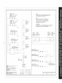
to
TOP Bb_NER LGNI TER
OPT [ONAL
OLJEMADOR DE E'\OEND DO SUPERIOR
DPC I ONAL
_:)UG IE D' ALLb,_AGE BRL_ EUR
TOP BUF;I_:ER iGNITER
OPT /ONAI
OUEMAF>OR DE ENCENOIDU BUrR/OR
OPCIO_
B0bO I E D" ALLUHADE-Bia_t.EUR
FACULTAT I F
IGNITER MODULE BOARD
CUADRO DE MODULO DE ENCENDIO0
N ALLLMEUR
L @
o @
DISCONNECT POWER BEFORE SERVICING UNT
DESCONECTE LA ENEF_GIA ANTES DE _EALIZAR
EL MANTENIMIENIO DEL ELEC-RODOP_STIEO
AVERT ISEMENT
_URANT AVANT D'EFFECTDER LA
F#EPARA T]ON
COLOR CODE / COD DOS DE C_.OR / CODE CO_EUR
B_BLACK / NEGRO / NO_R
"1
_ITE / RANBO / _AT',O
RIGHT REAR
I[ IGNSW
J [ IN]E_:TRASERO
i[
i [ OERFCP_
i [ INTERALLUM
II OAR
i i LEFT REAR
i [
i _ lGN SW
I [ I NT ENC TRASERO
i IZO_ IERDO
4[ r ]NTER ALLU'M
G AR
LEFT FRONT
LGN SW
[NTENC DE
FRENTE IZOU[ER]O
LNTERALLU_
G AV
I [ RIOCT FRONT
I I I G\ SW
i i ]NT. ENC _-
I I FRENTE DERECHO
II INTER AUL_
D AV
BK
DuNMocs
EMPALME
C(tNNECTEUR
GROUND
PDESTA A TIERRA
MBE A LA TERRE
POWER CORD
PARA TRANSPORTE
DE YUFRZA
CA_E
O' ALI NENTAT I ON
2 18 200
I 20 150
_]RE GAGE
ALAMBRE MEDiOA TEMP'C
FJL CAL
3304
3321
UL STYLE
MOOD UL
STYLE UL
iL]
CAUTION:
LABEL ALL WIRES PRIOR TO DISCONNECTION WHEN SERVICING CONTROLS
_IRIM] E_OR CAN CAbbiE [_R{_ER A_ DANGEWOb<_ OPTRATION
VERIFY PROPER ORERA_]_ AFTER DERVICIKG
AVISO:
ETIOL_TE TO_S LOS ALAMBRES ANTES DE DESCOWEC_AR PAR
REALIZAR ET MANTENIM[ENTO EE LOS CGqTROLES. ERROR DE
ALAHO_A._ PJDEDU CAUSAR UN FUNCIONAM]ENTO [NCOF_ECTO
Y PEL]GROSOVER[ODE BI EL FUNC/ONAM]ENTO ESTA
CORREOTO OESPbES [:)ELMANTENIMIENTO
AVER]ISSEMENT:
ETIOLETER CHA_JE FIL AVANT LE DEBRANCFEMENT DE CEUX-CiUNE ERREUR DE
8RANCHEMENT PEUT CAbSER UNE OPERATION DANDEREUSEVERIFLER LE BeN
FONCTIONNEMENT DE L'A;:>PAREIL APRES TOUTE REPARATION
RIGHT FRONT _EFT FRONT
]GNSW iGNSW
]NT ENC DE iNTENC DE
_RENTE DEREGHC FRFJNTE IZOU_ERO0
INTERALLUM INTERALLUM
DAV GAV
TOP _RNER IGNITER
G_EM_OR DE E_ENOIDO SUPERI_
BOUGIE D'ALLUMADE-BRULEUR _
TOP C:_JRNER IGNITER
DUEHADOR DE ENCENDIDU Bb_BRIOR
BOUGiE D'ALLUMADE-BRULEUR _
TOP BURNER iGNITER
OUEMA[2OR DE ENCEND_DO SUPERIOR
BOOGIE D'ALLUMAOS-BRCEEUR _
TOP _:_JRNfR IGNITER
CEJE"[AOO'_DE ENCENDIDO SL_ER}OR
BOUGIE D" ALLUMAGE-BRULEDR
LEFT REAR RIGHT REAR
IGNS_ ION SW
INTENCTRASERO ]N]ENC[RABERO
IZOUIERO0 BERECHO
]NTERA_LUM INTERALLUM
GAR OAR
L_
O 0 N©
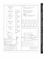
I 318047111
IGNITER MODULE BOARD
CUADRO DE MODULO DE ENOENDIOO
BLOC CONNECTION ALLUHEUR
REV. B

o
C;_ [3LJ_N R ]ON ER
Ob_',IDS_ OF NC [XU]DO UPROR
I_JGiE rl'R[ LLJ_AGE E_RtJl EUR
OP 8LRN V: ](} ER
0 JE'_ADC ':_, D£ EN(}_NI}I}O SUPE OI
BOtJQ J E D' £L -U'_AGE 8LJL ER
.'}1 U_N]R ](}fl ] ][R
QUEM_DQR DE ENC NOJDQ ,U° [ [OR
BOUG E D" _LLU_&G RULEU_
}iR
TOP BURN QN I TER
QU bADO*¢ DE ENCEND DO SU©E OR
i!iOU(}iE D" AIJ UMAGE B_Ui I!iLJR
IJ TE _4}{}k }::_D
C _:DRO DE IOOLO D ENCN DO
BiOC CONNECTION _°:_ _'_'_
U'A_N [ NG
O ! C(}NN CT i:s(},i ]F_ cl FO_] rE N3 LN
A,,, ISO
DESCONEC/_ i ,s _NER(} I _ AN I ES DE i_EAL i ZAi_
EL _AN[ENiMiEN/O OEt ELECT_ODOHi_STJCO
DiSCONN_CF POWER DEFO[_E 5EF_v[C[NO UN[ {
AvER T 155EMEN f
_EP&RAT ION
QqT R A_
] G\ S_,,'
]NT NC TR%S RO
OERECI i()
] NTE_ AL I U_
_4 R4
R_ R4
FRENTE ]Z0 JERDO
[ [R At i LM
0 A,i
GI] RON]
]ON 5,,,
NT [N( {}!
FRENT GERCO
I NE_ t <
DAV
( NIIRi IRi\_
QN S,,
N EN.'} ( NTRO
RAERO
_1 J
C aR
I}()NN C O
_FAL IE
30NNECTEUR
GROUND
I'IISE % LA TERRE
DE FUEF_Z_
C_B_ E
4 20 i50 C j 338
8 200 C J 3304 ;i< [!_I _'CK / [OR() / N',}IR
S PO0" ¢"
i ]_ _50_C j 332i _ RE() / ROJ© / ROUGE
_ i _ WJi]iE / BL_NCO / BLANC
!
_iRE IG¸i_¸G_ I Ut S!Yi E I L)R } )E / O) G)£ D L R /
_ _ _11'I :O )_! I[ : _p " C _© L l
i ¸I _ " _ ....... c/ %' _ i" COuE uOULLU_
LI
CAUT ION;
I,q_" A _,1 _11 [ I<(_N (F_ 'IN _F/v (IN ( NI[!( %
,,, N( El Oi £N (At3 Hi '}(1_ _ND ):NG lOtS O1 R_ (N
,/ R[: _ROPEI Of IAT [ON _[
AVISO:
E r J(} ET ]ODOr; 10 _-GblJl:_bb AN[ E D D -/ON C],_R I: ;d:_
R/[ Z_IR I"ANENI [ N( _; LO UON]R£ S R()R D
_ _cN IA. ILl C,_J_A_ LN UN( 1.2\qbl N]O NCORRFC[O
Y _ GROt40 V R (kE SI EL UNCIO\AH N]O ES/A
(()4_ (]O }E%F J _ I viNf N M iXT)
AVERT IS_NENT :
E IO{;ETER CHAOL_ FIL AVAN- i_ OEBRANCI_ENEN- DE EEUX C] UNt ERRtLJ_ DE
BF_ANCI_ENI ¸ I_EUi¸ CAUSER UN _ OPE_]iON D_NGE _LUSE VEIR[F i_l_ LE BEN
FONCiiO\_\tNENI DE L'APPAREII AP_-5 OUTE RE_A_A iON
CEN E M_AR RIG}[ FF/ON] E / iRON] LE_ RFAR R](}k [ RFAR
IN] ENE CEN/!RO [Ni ENC DE I NT E_ D_ IN] ENC iRASERO [NT ENC _RASERO
]!RRSERO !_RLN]F DFRECliO _REN[E tZOUiEF©O ]ZOUiE£;O D_RECi_O
]NiE_ A_{ UN [N[hN _Ii i U_ INiE_ Ai L U_ ]NIER RL! iJM [NI_R AL t U_
C AR D AV G AV G AP, © AR
[ i
OP 8JRN IGN] TER
(]UI V!DO[ 3E INC N9i[ 3JP[I: (
B(k(}IE l'_t kJ _ E I:iJt ELJIR
rOTE :
{ _,'IC : I} qCEMN] OF ]i,d INA } I {COME N CE q:_,Y COb{! Risi; { ,_ ql YP[ _\N[}
(_(} (NO (}()lSA al R ]N4i IUS] B USI}
NO ]A
IN EASO {;( ]8_ \[{E!AF!IO I}E IE H{ qZg_ 0{ IORNE E NEE{{SA[( O I)E UTII ZAR
E F/ISO TRO DE "[4VR Y D ['_ DIDOR Y [ SF/O TJPO D sORNES
10 F
SE '_ICE:SI DES F: ILS Od ES COSSES DO],/ENI FIRE RE{4PL_CES, U] [L SEZ DES PIECES
DE C'_LIB_E El DE [?:ES EQUI'/&LEN S
3180471 12 REV. A
-
 1
1
-
 2
2
-
 3
3
-
 4
4
-
 5
5
-
 6
6
-
 7
7
-
 8
8
-
 9
9
-
 10
10
-
 11
11
-
 12
12
-
 13
13
-
 14
14
-
 15
15
-
 16
16
-
 17
17
-
 18
18
-
 19
19
-
 20
20


Kenmore Elite 79032473800 Guía de instalación
- Tipo
- Guía de instalación
- Este manual también es adecuado para
en otros idiomas
Artículos relacionados
Otros documentos
-
Electrolux 36 Manual de usuario
-
Frigidaire FGC30S4DBA Guía de instalación
-
Electrolux EW30GC55G Manual de usuario
-
-
Kenmore Pro 79031013601 Guía de instalación
-
Frigidaire FFGC3625LB Guía de instalación
-
Frigidaire FFGC3025LB Guía de instalación
-
Frigidaire FFGC3015LSB Guía de instalación
-
Kenmore Pro Pro 36'' Gas Drop In Cooktop Guía de instalación
-
Electrolux EW36GC55GW2 Guía de instalación