
ENGLISH ESPAÑOL
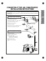
CONVERTIBLE TYPE AIR CONDITIONERS
INSTALLATION INSTRUCTIONS
• Please read this instruction manual completely before installing the product.
• When the power cord is to be replaced, replacement work shall be performed by authorized
personnel only.
• Installation work must be performed in accordance with national wiring standards by authorized
personnel only.
P/No.: 3828A30018L
1
2
3
4
10
11
12
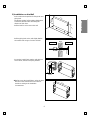
(Ceiling/Wall Mounting)
(Floor Mounting)
5
6
more than
10cm
more than
70cm
more than
10cm
more than
10cm
9
8
7
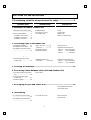
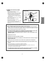
➀ Installation Plate (2pcs)
➁ Washer Bolt (M8 x L25, 4pcs, type "A")
➂ Floor Mount Bracket (1pcs)
➃ Drain Hose, Insulated
➄ Remocon Holder
➅ Screw for Remocon Holder(type "B")
➆ Drain Hose Hanger and screw
➇ Suspension Bolt
➈ Bolts for Mount Bracket
➉ Connecting Tube
• Gas side : Ø12.7/Ø15.88
• Liquid side : Ø6.35/Ø9.52
Connecting Cable
Drain Hose Extended
Installation Parts Provided
The other Installation Parts Needed
11
12

1.The following should be always observed for safety...............................3
2. Installation of Indoor, Outdoor unit
3. Connecting Pipes to the Indoor Unit
4. Connecting Pipes to the Outdoor Unit
5. Checking the Drainage..............................................................................15
6. Connecting Cables between Indoor Unit and Outdoor Unit
7. Air Purging of Pipes and Indoor Unit ......................................................19
8. Test running
OUT-LINE OF INSTALLATION
Installation works Installation Parts Required tools
1)
Selection of the best location
...
.............................................4
2) Indoor unit installation ..............5
Installation on the ceiling..........5
Installation on the wall..............9
Installation on the floor ...........11
•
Installation Plate
•
Four Type “A” screws
•
Connecting cable
•
Level
•
Screw driver
•
Electric drill
•
Hole core drill (ø70mm)
1) Preparation of Piping.............12
2) Installation on the ceiling .......13
3) Installation on the wall or floor...
...................................................14
•
Pipes: Gas side .....
1
/
2
",
5
/
8
"
Liquid side .............
1
/
4
",
3
/
8
"
•
Insulated drain hose
•
Insulation materials
•
Flaring Tools set
•
Specified Torque Wrenches
1.8kg·m ...... Liquid side piping
5.5kg·m ......... Gas side piping
Spanner ................. Half union
1) Connecting the pipes to the
Outdoor Unit...........................15
•
Additional Drain hose
(Outer Dia...............15.5mm)
•
Specified Torque Wrenches
1.8kg·m ...... Liquid side piping
5.5kg·m ......... Gas side piping
1) Connecting cables to the Indoor
Unit.........................................16
2) Connecting cables to the
Outdoor Unit...........................17
3) Form the pipings.....................18
•
Screw driver
•
Hexagonal Wrench (4mm)
•
Gas-leak Detector
1) Connection of power supply......
....................................................20
2) Evaluation of the performance
....................................................20
•
Two type “B” screws
•
Owner’s Manual
•
Thermometer
2

ENGLISH
3
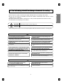
1. The following should be always observed for safety
• Please report to or take consent by the supply authority before connecting to the system.
• Be sure to read "THE FOLLOWING SHOULD BE ALWAYS OBSERVED FOR SAFETY" before
installing the air conditioner.
• Be sure to observe the cautions specified here as they include important items related to safety.
• The indications and meanings are as follows.
• After reading this manual, be sure to keep it together with the instruction manual in a handy place .
Could lead to death, serious injury, etc.
Do not install it yourself (customer).
Perform the installation securely referring to the
installation manual.
Install the unit securely in a place which can bear the
weight of the unit.
Perform electrical work according to the installation
manual and be sure to use an exclusive circuit.
Attach the electrical part cover to the indoor unit and
the service panel to the outdoor unit securely.
Be sure to use the part provided or specified parts for
the installation work.
Check that the refrigerant gas do not leak after
installation is completed.
Perform the drainage/piping work securely
according to the installation manual.
Use the specified wires to connect the indoor and the
outdoor units securely and attach the wires firmly to
the terminal board connecting sections so the stress
of the wires is not applied to the sections.
• Incomplete installation could cause injury due to fire, electric shock,
the unit falling or a leakage of water. Consult the dealer from whom
you purchased the unit or special installer.
• Incomplete installation could cause a personal injury due to
fire, electric shock, the unit falling or a leakage of water.
• When installed in an insufficient strong place, the unit could fall
causing injured.
• Incomplete connecting and fixing could cause fire.
• If the capacity of the power circuit is insufficient or there is
incomplete electrical work, it could result in a fire or an electric
shock.
• The use of defective parts could cause an injury or leakage of
water due to a fire, electric shock, the unit falling, etc.
• If there is a defect in the drainage/piping work, water
could drop from the unit and household goods could be
wet and damaged.
Do not install the unit in a place where an
inflammable gas leaks.
• If gas leaks and accumulates in the area surrounding the unit, it
could cause an explosion.
• If the electrical part cover if the indoor unit and/or the service
panel if the outdoor unit are not attached securely, it could result
in a fire or electric shock due to dust, water, etc.
Could lead to serious injury in particular environments when operated incorrectly.
WARNING
WARNING
CAUTION
CAUTION

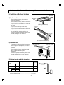
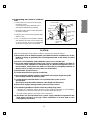
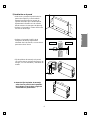
1. Selection of the best location
1) Indoor unit
• There should not be any heat source or
steam near the unit.
• There should not be any obstacles to prevent
the air circulation.
• A place where air circulation in the room will
be good.
• A place where drainage can be easily
obtained.
• A place where noise prevention is taken into
consideration.
• Do not install the unit near the door way.
• Ensure the spaces indicated by arrows from
the wall, ceiling, or other obstacles.
2) Outdoor unit
• If an awning is built over the unit to prevent
direct sunlight or rain exposure, be careful
that heat radiation from the condenser is not
restricted.
• There should not be any animals or plants
which could be affected by hot air
discharged.
• Ensure the spaces indicated by arrows from
the wall, ceiling, fence or other obstacles.
3) Piping length and the elevation
4
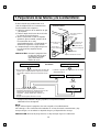
2. Installation of Indoor, Outdoor Unit
More than
20cm
More than eye-level
More than
20cm
R
R
More than
20cm
More than
20cm
(Ceiling installation)
(Floor/Wall installation)
More than 10cm
More than 10cm
More than 70cm
Indoor unit
Outdoor unit
B
A
MODEL
18K BTU
1/2" 1/4" 7 15
24K BTU
5/8" 1/4"
7 20
5/8" 3/8"
GAS LIQUID
50Hz
60Hz
5 8 30
5 8 30
Elevation B(m)
Length A(m)
* Additional
refrigerant
(g/m)
Pipe Size
Rated Rated
Max. Max.
• If 18K or 24K Model is installed at a distance of 15m, 240g of
refrigerant should be added.............................................(15-7)x30g

ENGLISH
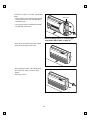
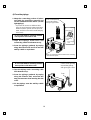
2. Indoor unit installation
■ Before Installing, prepare Installation
Plates
• 'Installation Plates' are attached at the bottom
of indoor unit.
Detach them by removing each 3 screws at
both sides.
• Detach 'Side Plate (R,L)' by removing each 2
screws on both sides.
• Pull the upper right and left side of 'Inlet Grille'
to the front, and it will stop at slightly tilted
position.
• Unhook the 'Inlet hanger' from the 'Hanger
screw' on the both left and right side.
• Detach the 'Inlet Grille' from the Indoor Unit.
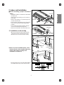
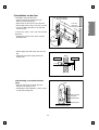
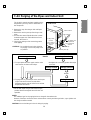
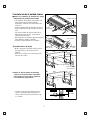
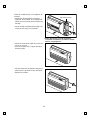
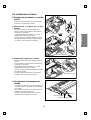
1) Installation on the ceiling
• Measure and mark the position for the
Suspension bolts and the piping hole.
• Drill the hole for anchor nut on the ceiling.
✱ Before secure the Installation Plates, select
the bent direction of the Installion Plate to the
inside or the outside according to the
installation circumstances.
• Drill the piping hole on the wall slightly tilted to
the outdoor side using a ø70 hole-core drill.
5
R
1076
Suspension
bolt
Center-line for the
piping hole
265
1236
265
Install Plate
1)
2)
R
5~7mm
Indoor Outdoor
WALL
Side Plate
Inlet Grille
Inlet hanger
Hanger
screw

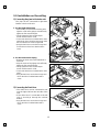
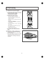
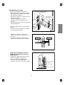
• Insert the nuts and washer onto the
suspension bolts for locking the suspension
bolts on the ceiling.
• Mount the suspension bolts to the anchor-
nuts firmly.
• Secure the Installation plates onto the
Suspension bolts (adjust level roughly.) using
nuts, washers and spring washers.
• Engage 2 hooks on the both left and
right side of the unit to the lower slot of
Installation Plates.
• Adjust a level with a level gauge on the
direction of left-right, back-forth by
adjusting suspension bolts.
• Move the hooks on the unit to the upper
slot of Installation Plates. Then the unit
will be declined to the bottomside so as
to drain well.
Washer
Nut
Suspension
bolts
Ceiling
Anchor nut
Suspension
bolts
Spring
washer
Max.
12mm
Washer
Nut
1)
2)
Suspension
bolt
Installation plate
Adjust a level
R
Level gauge
Lower slot
R
R
Upper slot
6

ENGLISH
Drain hose
Ceiling
Ceiling
Ceiling
7
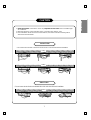
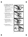
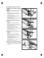
Front of view
Side of view
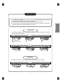
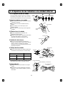
1. Install declination of the indoor unit is very important for the drain of the convertible type
air conditioner.
2. Minimum thickness of the insulation for the connecting pipe shall be 7mm.
3. If the Installation Plates are fixed to horizontal line, the indoor unit after installing will be
declined to the bottomside.
CAUTION
• The unit must be horizontal or declined to the drain hose connected when finished installation.
• The unit must be declined to the bottomside of the unit when finished installation.

8
R
R
R
1
2
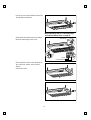
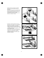
•
Before working, refer to "Connecting pipe
and cable to Indoor Unit" on page 12.
R
Inlet hanger
Hook
Cabinet Bottom
• Secure the unit to the Installation Plates with
four M8 bolts and washers.
• Hook up the Inlet Grille Hook to the cabinet.
• Hang the Inlet Hanger to the screw.
• Fit the projection hooks of the side plates to
the 'Side Panel' and the 'Front Panel' by
lifting it.
• Fasten the screws.

ENGLISH
9
1076
more than
260
265
Washer
Nut
Wall
Anchor nut
Spring
washer
Wall
5~7mm
Less than
12mm
1236
Indoor Outdoor
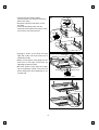
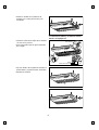
2) Installation on the Wall
• Select and mark the position for fixing bolts and
piping hole.
Decide the position for fixing bolts slightly tilted
to the drain direction after considering the
direction of drain hose.
• Drill the hole for anchor nut on the wall.
• Drill the piping hole on the wall slightly tilted to
the outdoor side using a ø70 hole-core drill.
• Secure the 'Install Plate' onto the wall with four
anchor bolts, washers and spring washers.
✱ Before secure the Install Plates, select the bent
direction of the 'Install Plate' to the inside or
outside according to the installation
circumstances.

10
Install the Indoor unit onto Installation
Plate.
• Insert 2 hooks on the both left and right side
of the unit to the inner slot (wall side) of the
Installation Plate.
• Secure the unit to the Installation Plate with
four M8 bolts and washers.
• Hook up the Inlet Grille Hook to the cabinet.
• Hang the Inlet Hanger to the screw.
• Fit the projection hooks of the side plates to
the 'Side Panel' and the 'Front Panel' by
lifting it.
• Fasten the screws.
R
2
1
•
Before working, refer to "Connecting pipe
and cable to Indoor Unit" on page 12.
Inner slot

ENGLISH
11
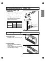
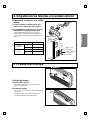
3) Installation on the floor
Installation of Mount Bracket.
• Select and mark the position for Mount
Brackets and the piping hole.
• Drill the hole for the anchor nut on the wall.
• Drill the piping hole using a ø70 hole-core drill.
• Secure the Mount Brackets on the wall with
four M4 screws.
Install the indoor unit onto the Mount
Brackets.
• Engage the slot at the back of the unit with
Mount Bracket.
• Drill the piping hole with 70mm dia, hole core
drill.
• Piping hole should be slightly slant to the
outdoor side.
After Installing, reassemble detached
parts.
• Hang the 'Inlet Grille' and hook the 'Inlet
Hanger' to the Hanger Screw.
• Assemble the 'Side Plates(R,L)' with 2 screws
on both left and right side.
Floor mount
bracket
Install plate
Slot
Piping hole
Wall
5~7mm
Indoor Outdoor
Wall
Floor mount
bracket
Slot
more than 760mm
From the left wall
From the
right wall
more than 840mm
448mm

12
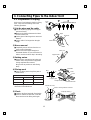
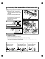
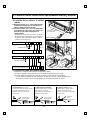
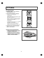
3-1. Preparation of Piping
3. Connecting Pipes to the Indoor Unit
Main cause of gas leakage is defect in flaring
work. Carry out correct flaring work in the
following procedure.
1) Cut the pipes and the cable.
■ Use the accessory piping kit or the pipes
purchased locally.
■ Measure the distance between the indoor
and the outdoor unit.
■ Cut the pipes a little longer than measured
distance.
■ Cut the cable 1.5m longer than the pipe
length.
2) Burrs removal
■ Completely remove all burrs from the cut
cross section of pipe/tube.
■ Put the end of the copper tube/pipe to
downward direction as you remove burrs in
order to avoid to let burrs drop in the tubing.
3) Putting nut on
■ Remove flare nuts attached to indoor and
outdoor units, than put them on pipe/tube
having completed burr removal.
(Not possibe to put them on after flaring
work)
4) Flaring work
■ Carry out flaring work using flaring tool as
shown below.
Firmly hold copper tube in a die as indicated
dimension in the table above.
5) Check
■ Compare the flared work with figure below.
■ If flare is noted to be defective, cut off the
flared section and do flaring work again.
Copper
tube
90°
Slanted Uneven Rough
Pipe
Reamer
Point down
Flare nut
Copper tube
Bar
Copper pipe
Clamp handle
Red arrow mark
Cone
Yoke
Handle
Bar
"A"
Inclined
Inside is shining without scratches
Smooth all round
Even length
all round
Surface
damaged
Cracked Uneven
thickness
= Improper flaring =
Outside diameter A
mm inch mm
Ø12.7 1/2 0~0.5
Ø15.88 5/8 0~1.0

ENGLISH
3-2. Installation on the ceiling
1)
Connecting the pipes to the indoor unit
The pipe can be connected to right side,
bottom or back of the unit.
1. For the Right Side Piping
• After bending an end of the connecting tube,
align the center of the pipings and sufficiently
tighten the flare nut with fingers.
• Finally, tighten the flare nut with torque
wrench until the wrench clicks.
• Connect the Drain Hose insulated to the drain
outlet. Drain hose should be go through under
the Hose Bracket as shown in figure ❹.
• Hang the drain hose on the hose hanger and
fix it to the hole of the hose bracket with a
screw.
2. For the Bottom Side Piping
• Remove the knock-out on the bottomside of
Inlet Grille
• Align the center of the pipings and sufficiently
tighten the flare nut with fingers.
• Finally, tighten the flare nut with torque
wrench until the wrench clicks.
• Connect the Drain Hose insulated to the drain
outlet.
• Hang the drain hose on the hose hanger and
fix it to the hole of cabinet bottom with a
screw.
2)
Connecting the Drain Hose
• The drain hose can be connected to not
only the right side but also left side of the
unit.
• If the drain hose is connected to the left
side, it should go through the cabinet
bottom.
• Hang the drain hose on the hose hanger and
fix it to the hole of cabinet bottom with a
screw.
13
R
R
R
Drain Hose
BOTTOM
Drain Hose
Hose Hanger
Piping
Hose
Bracket
1
3
4
5
2
Hose Hanger
Hose
Hanger

3-3.
Installation on the wall or floor
1)
Connecting the pipes to the indoor unit
1. For the Right Rear Piping
• Remove the knock-out at the back side of the
cabinet.
• After bending an end of the connecting tube,
align the center of the pipings and sufficiently
tighten the flare nut with fingers.
• Finally, tighten the flare nut with torque
wrench until the wrench clicks.
• Connect the Drain Hose insulated to the
drain outlet.
• Tape the Drain Hose to the pipings to avoid
coming off the drain-outlet.
2. For the Right Side Piping
• After bending an end of the connecting tube,
align the center of the pipings and sufficiently
tighten the flare nut with fingers.
• Finally, tighten the flare nut with torque
wrench until the wrench clicks.
• Connect the Drain Hose insulated to the
drain outlet.
• Tape the Drain Hose to the pipings to avoid
coming off the drain-outlet.
3.
For the Right Bottom Piping
• Align the center of the pipings and sufficiently
tighten the flare nut with fingers.
• Finally, tighten the flare nut with torque
wrench until the wrench clicks.
• Connect the Drain Hose insulated to the
drain outlet.
2)
Connecting the Drain Hose
• The drain hose can be connected to not only
right side but also left side of the unit.
14
Taping
Drain Hose
Piping
Piping
Drain Hose
Connecting
Cable
Drain Hose
Piping
Drain Hose
REAR
BOTTOM
Taping
Taping

1) Connecting the pipes to the
Outdoor unit
1. Align the center of the pipings and
sufficiently tighten the flare nut with
fingers.
2. Finally, tighten the flare nut with torque
wrench until the wrench clicks.
• When tightening the flare nut with torque
wrench, ensure the direction for tightening
follows the arrow on the wrench.
1) Checking the Drainage
1. Remove the Air Filter.
• To remove air filter, take hold of tab and
pull slightly upwards.
2. Check the drainage.
• Spray one or two glasses of water upon
the evaporator.
• Ensure that water flows drain hose of
indoor unit without any leakage.
4. Connecting Pipes to the Outdoor Unit
5. Checking the Drainage
15
ENGLISH
R
Liquid side piping
(Smaller Dia.)
Gas side piping
(Bigger Dia.)
Torque wrench
Outdoor unit
R
Pipe Size Torque
Liquid Side
1/4" 1.8kg·m
3/8" 4.2kg·m
Gas Side
1/2" 5.5kg·m
5/8" 6.6kg·m

1) Connecting cables to the Indoor
Unit
1) Remove the Air guide - L by loosening 2
screws after removing the Inlet grille from the
Indoor unit.
2) Connect the wires to the terminals on the
control board individually according to the
outdoor unit connection.
• Ensure that the color of the wires of outdoor
unit and the terminal No. are the same as
those of indoor unit respectively
R
Terminals on the indoor unit
POWER
INPUT
GN/YL
POWER
INPUT
GN/YL
Terminals on the indoor unit
1(L) 2(N)
3 4
Terminals on the outdoor unit
3 4
Terminals on the outdoor unit
3 4
5 6 7
1(L) 2(N)
3 4 5 6 7 8
AIR GUIDE-L
INDOOR UNIT
Control
Panel
• Cooling & Heating type
• Cooling only type
1
2
Clamp
The power cord connected to the
indoor unit should be complied with
the following specifications
(Type H05VV-F(Indoor)
approved by HAR or SAA).
The power connecting cable
connected between the indoor and
outdoor unit should be complied
with the following specifications
(Type H07RN-F approved by HAR or SAA).
The connecting cable connected
between the indoor and outdoor unit
should be complied with the
following specifications
(Type H07RN-F approved by HAR or SAA).
CAUTION
•
•
•
•
•
•
16
6. Connecting Cables between Indoor Unit and Outdoor Unit
2) Clamping of cables
1) Arrange 2 power cables on the control panel.
2) First, fasten the steel clamp with a screw to the inner boss of control panel.
3) For the cooling model, fix the other side of the clamp with a screw strongly.
For the heat pump model, put the 0.75mm
2
cable(thinner cable) on the clamp and tighten it with a
plastic clamp to the other boss of the control panel.

3) Connecting the cable to Outdoor
Unit
1. Remove the Cover control from the unit by
loosening a screw.
Connect the wires to the terminals on the
control board individually as following.
2. Secure the cable onto the control board with
the holder (clamper).
3. Refix the cover control to the original position
with the screw.
4. Use a recongnized circuit breaker 20A(18K,
24K) between the power source and the unit.
A disconnection device to adequately
disconnect all supply lines must be fitted.
17
ENGLISH
CAUTION
After the confirmation of the above conditions, prepare the wiring as follows:
1) Never fail to have an individual power specialized for the air conditioner. As for the
method of wiring, be guided by the circuit diagram pasted on the inside of control
box cover.
2) Provide a circuit breaker switch between power source and the unit.
3) The screw which fasten the wiring in the casing of electrical fittings are liable to
come loose from vibrations to which the unit is subjected during the course of
transportation. Check them and make sure that they are all tightly fastened. (If
they are loose, it could give rise to burn-out of the wires.)
4) Specification of power source
5) Confirm that electrical capacity is sufficient.
6) Be sure that the starting voltage is maintained at more than 90 percent of the
rated voltage marked on the name plate.
7) Confirm that the cable thickness is as specified in the power sources
specification.
(Particularly note the relation between cable length and thickness.)
8) Never fail to equip a leakage breaker where it is wet or moist.
9) The following troubles would be caused by voltage drop-down.
• Vibration of a magnetic switch, damage on the contact point there of, fuse breaking,
disturbance to the normal function of a overload protection device.
• Proper starting power is not given to the compressor.
10) The means for disconnection from a power supply shall be incorporated in the
fixed wiring and have an air gap contact separation of at least 3mm in each
active(phase) conductors.
Outdoor unit
Terminal block
Connecting
cable
Cover control
Holder for
connecting
cable
Over 5mm
Holder for
power supply
cord
Power supply
cord

4) Form the pipings
1. Wrap the connecting portion of indoor
unit with the Insulation material and
secure it with two Plastic Bands. (for the
right pipings)
• If you want to connect an additional drain
hose, the end of the drain-outlet should keep
distance from the ground. (Do not dip it into
water, and fix it on the wall to avoid swinging
in the wind.)
2. Tape the Pipings, drain hose and
Connecting Cable from bottom to top.
3. Form the pipings gathered by taping
along the exterior wall and fix it onto the
wall by saddle or equivalent.
2. Tape the Pipings and Connecting cable
from bottom to top.
3. Form the pipings gathered by taping
along the exterior wall, and make the
trap prevent water from entering into the
room.
4. Fix the pipings onto the wall by saddle
or equivalent.
18
In case of the Outdoor unit being installed
below position of the Indoor unit.
In case of the Outdoor Unit being installed
above position of the Indoor Unit.
Trap is required to prevent water from entering
into electrical parts.
Seal a small opening
around the pipings
with gum type sealer.
Taping
Drain hose
Pipings
Connecting
cable
Plastic Band
Power supply
cord
Seal a small opening
around the pipings
with gum type sealer.
Trap

The air which contains moisture remaining in the
refrigeration cycle may cause a malfunction on
the compressor.
1. Remove the caps from the gas side and liquid
side valves.
2. Remove the service-port cap from the gas side
valve.
3. Turn the valve stem of liquid side valve counter-
clockwise approx. 90° and hold it there for ten
seconds, then close it.
4. Check a gas-leakage of the connecting portion
of the pipings.
CAUTION : Do not leak the gas in the air during
air purging. Use vacuum pump as far
as possible.
7. Air Purging of the Pipes and Indoor Unit
19
ENGLISH
No leakage found leakage foundResult
leakage persists
leakage ceased
leakage ceased
Outdoor unit
Cover control
To indoor unit
Liquid side
Gas side
2-way valve or
3-way valve
(open)
3-way valve
(Close)
Cap
Service port cap
Hexagonal
wrench
5. To open liquid side valve again, turn the valve
stem counter-clockwise until it stops.
6. To purge the air, push the pin on the service port
of gas side valve for three seconds with a
hexagonal wrench and set it free for one minute.
Repeat this three times.
• Re-tighten the connecting portion with torque
wrenches.
Repair
7. Set the both liquid and gas side valves to open
position with the Hexagonal wrench for the unit
operation.
NOTE:
The additional gas for air purging has been charged in the outdoor unit.
However, if the flare connections have not been done correctly and there gas leaks, a gas cylinder and
the charge set will be needed.
CAUTION : Do not leak the gas in the air during air purging.

8. Test running
20
RESET
RESET
RESET
R
Thermometer
2) Evaluation of the performance
1. Measure the temperature of the intake
and discharge air.
2. Ensure the difference between the intake
temperature and the discharge one is
more than 8°C (Cooling) or reversely
(Heating).
1) Connection of power supply
1. Connect the power supply cord to the
independent power supply.
• Circuit breaker is required.
2. Prepare the remote control.
• Insert two batteries provided.
Remove the battery cover from the
remote controller.
• Slide the cover according to the arrow
direction.
Insert the two batteries.
(Two "R03" or "AAA" dry-cell batteries
or equivalent.)
• Be sure that the (+) and (-) directions
are correct.
• Be sure that both batteries are new.
Re-attach the cover.
• Slide it back into position.
3. Operate the unit for fifteen minutes or
more.

ESPAÑOLESPAÑOL
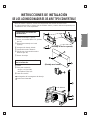
INSTRUCCIONES DE INSTALACIÓN
DE LOS ACONDICIONADORES DE AIRE TIPO CONVERTIBLE
• Antes de instalar el producto, sírvase leer íntegramente este manual de instrucciones.
• El cable de interconexión a instalar entre las unidades interior y exterior debe estar aprobado por la
normalización TÜV, u otra equivalente.
1
2
3
4
10
11
12
(Montaje en techo o pared)
(Montaje en el suelo)
5
6
más de10cm
más de
70cm
more than
10cm
más de
10cm
9
8
7
➀
Pletinas de montaje (2 piezas)
➁
Pernos con arandela (M8 x L25, 4 piezas,
tipo "A")
➂
Soporte para montaje en el suelo
(1 pieza)
➃
Manguera de drenaje, aislada
➄
Soporte del mando a distancia
➅
Tornillo para el soporte del mando a
distancia (tipo "B")
➆
Pernos de anclaje
➇
Pernos
➈
Tubo para conducción
•
de gas: ø 12,7/ø 15,88
•
de líquido:ø 6,35/ø 9,52
➉
Cable de conexión
Prolongador de la manguera de drenaje
Drain Hose Extended
Componentes de instalación
suministrados.
Otros componentes necesarios
para la instalación
11
12

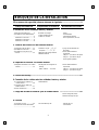
1.Por razones de seguridad, observe siempre lo siguiente.......................................3
2. Instalación de las unidades interior y exterior
3. Tuberías de conducción de la unidad interior
4. Empalme de tuberías a la unidad exterior
5. Prueba del drenaje ..................................................................................................15
6. Conexión de los cables entre las unidades interior y exterior
7. Purga del aire de las tuberías y de la unidad interior .........................................19
8. Pruebas
BOSQUEJO DE LA INSTALACIÓN
Trabajo de instalación
Componentes de instalacón Herramientas necesarias
1) Elección del mejor lugar
..........4
2) Instalación de la unidad interior..
......................................................5
Instalación en el techo..............5
Instalación en la pared..............9
Instalación en el suelo ............11
•
Pletinas de montaje
•
Cuatro tornillos tipo “A”.
•
Cable de conexión
• Nivel.
• Destornillador
• Taladradora eléctrica
• Broca pasamuros (70 mm)
1) Preparacón de los tubos........12
2) Instalación en el techo...........13
3) Instalación en la pared o en
el suelo....................................14
•
Tuberías: de gas .....
1
/
2
",
5
/
8
"
de líquido .............
1
/
4
",
3
/
8
"
•
Manguera de drenaje aislada
•
Material aislante
•
Juego de herramientas de
abocardar
•
Llaves dinamométricas
específicas:
1,8kg·m.....
para tuberías de líquidos
5,5kg·m ....
para tuberías de gas
Llave inglesa ajustable
1) Empalme de tuberías a la unidad
exterior...................................15
•
Prolongador de manguera de
drenaje
(Diám. externo .... 15,5 mm)
•
Llaves dinamométricas
específicas:
1,8kg·m.....
para tuberías de líquidos
5,5kg·m ....
para tuberías de gas
1) Conexión de los cables a la
unidad interior........................16
2) Conexión de los cables a la
unidad exterior........................17
3) Armar las tuberías..................18
•
Destornillador
•
Llave hexagonal (4 mm)
•
Detector de fugas de gas
1) Conexión a la red ..................20
2) Evaluación del funcionamiento
....................................................20
•
Dos tornillos tipo "B"
• Manual de uso
• Termómetro
2

ESPAÑOL
3
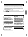
1. Por razones de seguridad, observe siempre lo siguiente:
• Sírvase comprobar que dispone de suficiente energía contratada del servicio público antes de conectar el
acondicionador de aire.
• No deje de leer este apartado “POR RAZONES DE SEGURIDAD, OBSERVE SIEMPRE LO SIGUIENTE”: antes
de proceder a la instalación del acondicionador de aire.
• Asegúrese de cumplir todas las medidas de precaución especificadas aquí, ya que en ellas se incluyen puntos
que conciernen a la seguridad.
• El significado de las indicaciones es como sigue:
•
Después de leer este manual procure tenerlo a mano, junto con el manual de uso.
Indica la posibilidad de lesiones serias e, incluso, la muerte.
No instale Vd. mismo (el cliente) el equipo.
Efectúe la instalación con seguridad, siguiendo el
manual de instalación.
Instale el aparato en un lugar seguro capaz
de sostener el peso.
Ejecute el cableado eléctrico de acuerdo con el manual de
instalación y asegúrese de usar una toma de red única.
Monte y asegure la tapa de la regleta de conexiones en
la unidad interior y el panel de servicio en la exterior.
Asegúrese de utilizar los componentes de montaje
suministrados o especificados para el trabajo de instalación.
Una vez completa la instalación, compruebe que
no hay fugas del gas refrigerante.
No instale el aparato en un lugar donde pueda
haber fugas de gas inflamable.
Emplee el calibre especificado de los cables para conectar las unidades
interior y exterior y sujételos firmemente con las abrazaderas de la regleta
terminal, de modo que no transmitan la tensión mecánica a las conexiones.
• Una instalación imperfecta puede dar lugar a lesiones por incendio,
descarga eléctrica, caída de un aparato, o fugas de agua. Consulte
con su distribuidor o con un instalador especialista.
• Una instalación imperfecta puede causar lesiones a personas por
fuego, descarga eléctrica, caída del aparato o fugas de agua.
• Si se monta el aparato en un lugar que no sea suficientemente
resistente, puede caer al suelo y producir lesiones.
• Las conexiones imperfectas por mala sujeción pueden causar incendio.
• Si la capacidad del circuito de alimentación es insuficiente,
o la instalacón eléctrica está mal terminada, puede ocurrir
incendio o descarga eléctrica.
• El uso de componentes defectuosos puede dar lugar a lesiones o fugas
de agua, por incendio, descarga eléctrica, caída del aparato, etc.
• Si el gas que escapa se acumula alrededor del
aparato, puede producirse una explosión.
Instale la tubería de drenaje de forma segura, de
acuerdo con el manual de instalación.
• Si hay defectos en el trabajo de montaje de la tubería
de drenaje, puede haber fugas de agua del aparato
que mojen los enseres de la casa.
• Si la tapa de los circuitos de la unidad interior, o el panel de servicio de
la unidad exterior, no están montados fijamente, se puede originar
incendio, o descarga eléctrica debido al polvo, agua, etc.
Indica la posibilidad de lesiones serias en situaciones particulares, si se procede incorrectamente.
CUIDADO
CUIDADO
PRECAUCIÓN
PRECAUCIÓN

1. Elección del mejor lugar
1) Unidad interior
• No debe haber estufa ni fuente de calor alguna en
la vecindad de la unidad.
• No deben existir obstáculos que impidan la
circulación del aire.
• Será bueno cualquier lugar de la habitación, por
donde circule el aire.
• Desde tal lugar debe ser fácil instalar el drenaje.
• Hay que tomar en consideración la molestia del
ruido.
• No instale la unidad cerca del camino de la puerta.
• Asegúrese de que quedan las distancias que
indican las flechas, hasta la pared, el techo, u otros
obstáculos.
2) La unidad exterior
• Si va a instalar una marquesina sobre la unidad
para impedir que esté expuesta al sol directamente,
o que le caiga la lluvia, ponga cuidado en no
impedir la radiación de calor del condensador.
• El aire caliente expelido no debe afectar a animales
o plantas.
• Asegúrese de que quedan las distancias que
indican las flechas, hasta la pared, el techo, u otros
obstáculos.
3) Longitud y altura de las tuberías
4
2. Instalación de las unidades interior y exterior
Más de
20cm
Más alto que el
nivel del ojo
Más de
20cm
R
R
Más de 20cm
Más de
20cm
(Instalación en el techo)
(Instalación en suelo o pared)
Más de
10cm
Más de
10cm
Más de
70cm
Unidad interior
Unidad exterior
B
A
MODELO
18K BTU
1/2" 1/4" 7 15
24K BTU
5/8" 1/4"
7 20
5/8" 3/8"
GAS LÍQUIDO
50Hz
60Hz
5 8 30
5 8 30
Altura B (m)
Longitud A (m)
*
Refrigerante
adicional
(g/m)
Tamaño de la tubería
Normal Normal
Máx. Máx.
• Si los modelos 18K o 24K se instalan a la distancia de 15 m, se debe
añadir 240g de refrigerante ...............................................(15-7) x 30g

ESPAÑOL
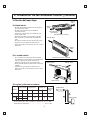
2. Instalación de la unidad interior
■ Antes de comenzar la instalación, tenga
dispuestas las pletinas de montaje
• Las Pletinas de montaje van sujetas a la
parte trasera de la unidad interior.
Sepárelas, retirando los tres tornillos de
cada una.
• Separe ambas pletinas laterales (izqda. y
dcha.) retirando los dos tornillos de cada
una.
• Tire hacia arriba de ambos lados de la
rejilla de la toma de aire. Se quedará
ligeramente inclinada.
• Desenganche los tornillos-guía que traban
esta rejilla por ambos costados.
• Separe la rejilla frontal de la unidad.
1) Instalación en el techo
• Mida y marque la posición de los pernos
de suspensión y del orificio para la
tubería.
• Perfore los orificios en el techo para las
tuercas de anclaje.
✱
Antes de fijar la pletina de montaje,
seleccione la posición de la pestaña,
hacia dentro o hacia fuera, según las
circunstancias particulares.
• Perfore en la pared el orificio para la
tubería, inclinado ligeramente hacia
fuera. Utilice una broca pasamuros de
ø = 70mm.
5
R
1076
Perno de suspensión
Centro del orificio
para la tubería
265
1236
265
Pletina
de montaje
1)
2)
R
5~7mm
Interior
Exterior
Pared
Pletina lateral
Rejilla de la
toma de aire
Guía lateral
Tornillo-
guía

• Inserte las tuercas de anclaje en los orificios
practicados en el techo para los pernos de
suspensión.
• Monte firmemente los pernos de suspensión con
sus tuercas y arandelas en las tuercas de anclaje.
• Sujete las pletinas de montaje a los pernos de
suspensión (procurando que queden
aproximadamente niveladas), mediante tuercas,
arandelas y arandelas de muelle.
• Inserte las uñetas laterales derecha e
izquierda de la unidad, en el alojamiento
inferior de las pletinas de montaje.
• Ajuste la posición horizontal subiendo y
bajando las tuercas de los pernos. Utilice
un nivel de burbuja.
• Inserte ahora las uñetas laterales en el
alojamiento superior de las pletinas de
montaje. De este modo el aparato
quedará inclinado hacia atrás, lo que
facilitará el drenaje.
Arandela
Tuerca
Perno de
suspensión
Techo
Tuerca de
anclaje
Perno de
suspensión
Arandela
de muelle
Máx.
12mm
Arandela
Tuerca
1)
2)
Perno de suspensión
Pletina de montaje
Nivelar
R
Nivel de burbuja
Alojamiento inferior
R
R
Alojamiento superior
6

ESPAÑOL
Manguera de drenaje
Techo
Techo
Techo
7
Vista frontal
Vista lateral
1. La instalación inclinada de la unidad interior es muy importante para el drenaje
en los acondicionadores de aire de tipo convertible.
2. El espesor mínimo del aislamiento de la tubería ha de ser de 7 mm.
3. Si las pletinas de montaje están puestas horizontalmente, al terminar la instalación
la unidad interior debe quedar inclinada hacia atrás.
PRECAUCIÓN
• Al terminar la instalación, la unidad debe quedar horizontal o inclinada hacia el lado
de la manguera de drenaje.
• Al terminar la instalación, la unidad debe quedar inclinada hacia el fondo.

8
R
R
R
1
2
• Antes de proceder, consulte el apartado
“Conexión de la tubería y el cable a la unidad
interior” en la página 12.
R
Guía lateral
Uñeta
Fondo de la carcasa
• Monte la unidad en las pletinas de
montaje con cuatro pernos M8 y sus
arandelas.
• Inserte la uñeta de la rejilla de la entrada
de aire en la carcasa.
• Pase los tornillos por las guías laterales
de la rejilla.
• Fije las uñetas de las pletinas laterales al
panel lateral y al panel frontal, alzándolo.
• Apriete los tornillos.

ESPAÑOL
9
1076
más de
260
265
Arandela
Tuerca
Pared
Tuerca de
anclaje
Arandela
de muelle
Pared
5~7mm
Menos de
12mm
1236
Interior Exterior
2) Instalación en la pared
• Seleccione y marque la posición de los
pernos de sujeción y la de la tubería.
Marque la posición de los pernos de
sujeción de modo que la unidad quede
ligeramente inclinada hacia el costado
donde entronca la manguera de drenaje.
• Perfore en la pared los cuatro orificios de
las tuercas de anclaje.
• Perfore en la pared el orificio de la
manguera de drenaje ligeramente
orientado hacia el exterior, con una broca
pasamuros de ø 70mm.
• Fije las pletinas de montaje a la pared
con cuatro pernos provistos de tuercas de
anclaje, con sus arandelas y arandelas de
muelle.
✱
Antes de fijar la pletina de montaje,
seleccione la posición de la pestaña,
hacia dentro o hacia fuera, según las
circunstancias particulares.

10
Instale la unidad interior en las pletinas de
montaje.
• Inserte las uñetas laterales derecha e
izquierda de la unidad, en el alojamiento
interior (hacia la pared) de las pletinas de
montaje.
• Fije la unidad a la pletina de montaje con
cuatro pernos M8 y sus arandelas.
• Inserte la uñeta de la rejilla de la toma de
aire en la carcasa.
• Pase los tornillos por las guías laterales
de dicha rejilla.
• Fije las uñetas de las pletinas laterales al
panel lateral y al panel frontal, alzándolo.
• Apriete los tornillos.
R
2
1
• Antes de proceder, consulte el apartado
“Conexión de la tubería y el cable a la unidad
interior” en la página 12.
alojamiento interior

ESPAÑOL
11
3) Instalación en el suelo
Instalación del soporte de montaje.
• Mida y marque en la pared la posición
del soporte, de las pletinas de montaje y
del orificio de la tubería.
• Perfore en la pared los orificios para las
tuercas de anclaje.
• Perfore el orificio para la tubería
utilizando una broca pasamuros de
ø70 mm
• Fije el soporte de montaje a la pared con
cuatro tornillos M4.
Instale la unidad interior en el soporte de
la pared.
• Encaje la ranura posterior de la unidad
en la pestaña del soporte.
• Perfore en la pared el orificio de la
tubería, con una broca pasamuros de
ø70 mm.
• El orificio de la tubería debe quedar
ligeramente orientado hacia el exterior.
Después de la instalación, vuelva a
montar los componentes que retiró
anteriormente.
• Enganche la rejilla de la toma de aire y
pase los tornillos por las guías.
• Monte las pletinas laterales (izqda. y
dcha.) en sus correspondientes
costados, cada una con sus dos tornillos.
Soporte para
montaje en
el suelo
Ranura
Soporte para montaje
en el suelo
Pletina de montaje
Ranura
Orificio para la tubería
Pared
5~7mm
Interior Exterior
Más de 760 mm hasta
la pared izquierda
448mm
Pared
Más de 840 mm
hasta la pared derecha

12
3-1. Preparación de los tubos
3. Empalme de las tuberías a la unidad interior
La causa principal de fugas de gas son los defectos
en el trabajo de abocardado. Lleve a cabo una labor
correcta de abocardamiento en los pasos que siguen.
1) Corte las tuberías y los cables
■ Utilice el juego de accesorios de tubería o tuberías
compradas localmente.
■ Mida la distancia entre las unidades interior y
exterior.
■ Corte los tubos un poco más largos que la
distancia medida.
■ Corte el cable 1,5 m más largo que la longitud de
la tubería.
2) Eliminación de la rebaba
■ Elimine completamente las rebabas de la
extremidad cortada del tubo.
■ Mientras retira las rebabas, dirija dicha extremidad
de la tubería hacia abajo, a fin de que los
fragmentos arrancados no penetren en ella.
3) Instalación de la tuerca
■ Una vez que haya terminado de eliminar las
rebabas, retire las tuercas valonas de las unidades
interior y exterior, e insértelas en la tubería.
(Después de que haya abocardado la tubería será
imposible introducirlas.)
4) Trabajo de abocardado
■ Efectúe el abocardado de las tuberías utilizando la
herramienta de abocardar que se muestra abajo.
Sujete firmemente el tubo de cobre sobre la matriz
de la métrica que se indica en la tabla de arriba.
5) Comprobación
■ Compare el trabajo de abocardado con la figura
adjunta.
■ Si descubre que el abocardamiento ha quedado
defectuoso, corte el extremo trabajado y vuelva a
abocardarlo.
Tubo
de cobre
90°
Torcido
Desigual
Basto
Tubo
Abocardador
Apunte hacia
abajo
Tuerca valona
Tubo de cobre
Horquilla
Tubería de cobre
Manivela de
sujeción
Flecha roja
Cono
Yugo
Empuñadura
Horquilla
"A"
Inclinado
Interior brillante y sin arañazos
Liso todo alrededor
Igual longitud
todo alrededor
Superficie
dañada
Rajado Espesor
desigual
Abocardamiento
incorrecto
==
Diámetro exterior
A
mm
pulgadas
mm
Ø12.7 1/2 0~0,5
Ø15.88 5/8 0~1,0

ESPAÑOL
3-2. Instalación en el techo
1) Empalme de las tuberías a la unidad
interior
La tubería se puede empalmar por el lado derecho,
por el fondo, o por detrás de la unidad.
1. Empalme de la tubería por el lado
derecho
• Después de doblar uno de los extremos de la
tubería, céntrela y apriete la tuerca valona todo lo
que pueda con los dedos.
• Luego apriete dicha tuerca valona con su llave
dinamométrica hasta que ésta suene.
• Acople la manguera aislada de drenaje a la tobera
de salida de drenaje. La manguera debe pasar por
su soporte, como se muestra en la figura 4.
2. Empalme de la tubería por el fondo
• Retire el protector del fondo de la rejilla de la toma
de aire.
• Centre la tubería y apriete la tuerca valona todo lo
que pueda con los dedos.
• Luego apriete dicha tuerca valona con su llave
dinamométrica hasta que ésta suene.
• Conecte la manguera aislada de drenaje a la tobera
de salida de drenaje.
• Cuelgue la manguera purgadora en el soporte y
atomillela a la parte inferior de la carcasa.
2) Acoplamiento de la manguera de
drenaje
• La manguera de drenaje se puede acoplar tanto por
el costado derecho, como por el costado izquierdo
de la unidad.
• Si se acopla la manguera por el costado izquierdo,
debe pasar a lo largo de la carcasa.
• Cuelgue la manguera purgadora en el soporte y
atomillela a la parte inferior de la carcasa.
13
R
R
R
Manguera de drenaje
FONDO
Manguera
de drenaje
Manguera de guía
Piping
Soporte
de la
manguera
1
3
4
5
2
Manguera de guía
Manguera de guía

3-3.
Instalación en la pared o en el suelo
1) Empalme de las tuberías a la unidad
interior
1. Empalme de la tubería por la parte trasera
derecha
• Retire la protección de la parte trasera de la
carcasa.
• Después de doblar uno de los extremos de la
tubería, céntrela y apriete la tuerca valona todo lo
que pueda con los dedos.
• Luego apriete dicha tuerca valona con su llave
dinamométrica hasta que ésta suene.
• Acople la manguera aislada de drenaje a la tobera
de salida de drenaje.
• Sujete la manguera de drenaje con cinta adhesiva a
las tuberías, para evitar que se salga.
2. Empalme de la tubería por el costado
derecho
• Retire la protección de la parte trasera de la
carcasa.
• Después de doblar uno de los extremos de la
tubería, céntrela y apriete la tuerca valona todo lo
que pueda con los dedos.
• Luego apriete dicha tuerca valona con su llave
dinamométrica hasta que ésta suene.
• Acople la manguera aislada de drenaje a la tobera
de salida de drenaje.
• Sujete la manguera de drenaje con cinta adhesiva a
las tuberías, para evitar que se salga.
3. Empalme de la tubería por el fondo y a
la derecha
• Retire la protección de la parte trasera de la
carcasa.
• Después de doblar uno de los extremos de la
tubería, céntrela y apriete la tuerca valona todo lo
que pueda con los dedos.
• Luego apriete dicha tuerca valona con su llave
dinamométrica hasta que ésta suene.
• Acople la manguera aislada de drenaje a la tobera
de salida de drenaje.
• Sujete la manguera de drenaje con cinta adhesiva a
las tuberías, para evitar que se salga.
2) Empalme de la manguera de drenaje
• La manguera de drenaje se puede acoplar tanto por
el costado derecho, como por el costado izquierdo
de la unidad.
14
Encintar
Manguera de drenaje
Tuberías
Tuberías
Manguera de drenaje
Cable de conexión
Manguera de drenaje
Tuberías
Manguera de drenaje
PARTE POSTERIOR
FONDO
Encintar
Encintar

1) Empalme de las tuberías a la unidad
exterior
1. Centre la tubería y apriete todo lo que
pueda con los dedos la tuerca valona.
2. Seguidamente, apriétela con su llave
dinamométrica hasta que ésta suene.
• Cuando apriete una tuerca valona con su llave
dinamométrica, asegúrese de que la dirección en
que lo está haciendo coincide con la de la flecha de
la llave.
1) Prueba del drenaje
1. Retire el filtro de aire.
• Para extraer el filtro de aire, tire de la lengüeta
ligeramente hacia arriba.
2. Prueba del drenaje
• Rocíe con un aerosol uno o dos vasos de agua en el
evaporador.
• Asegúrese de que el agua fluye sin fugas por la
manguera de drenaje de la unidad interior.
4. Empalme de las tuberías a la unidad exterior
5. Prueba del drenaje
15
ESPAÑOL
R
Tubería de líquidos
(menor diám.)
Tubería de gas
(mayor diám.)
Llave dinamométrica
Unidad exterior
R
Tamaño de la tubería Par
1/4" 1.8kg·m
3/8" 4.2kg·m
1/2" 5.5kg·m
5/8" 6.6kg·m
PARA
LÍQUIDOS
PARA
GASES

1) Conexión de los cables a la unidad
interior
1) Desmonte la guía en "L" para el flujo de aire,
soltando los tornillos que se descubren al
retirar la rejilla de la toma de aire.
2) Conecte los hilos uno a uno a los terminales
de la regleta de conexiones, de acuerdo con
la forma en que estén conectados a la
unidad exterior.
• Asegúrese de que el color de los hilos y el número
del terminal de la regleta al que van conectados es
el mismo en ambas unidades de interior y exterior.
R
Terminales de la unidad interior
VERDE/
AMARILLO
ENTRADA DE RED
ENTRADA DE RED
VERDE/
AMARILLO
Terminales de la unidad interior
1(L) 2(N)
3 4
Terminales de la unidad exterior
3 4
Terminales de la unidad exterior
3 4 5 6 7
1(L) 2(N)
3 4 5 6 7 8
GUÍA EN "L" PARA EL
FLUJO DE AIRE
UNIDAD INTERIOR
Panel de
Control
•
Modelo climatizador
•
Modelo sólo acondicionador
1
2
Abrazadera
El cable de fuerza de la unidad
interior debe cumplir las especificaciones
siguientes:(Tipo H05VV-F (interior),
H07RN-F (exterior) aprobado por
HAR ó SAA).
El cable de fuerza que alimenta
a ambas unidades interior y exterior
debe cumplir las siguientes
especificaciones: (Tipo H07RN-F
aprobado por HAR ó SAA).
El cable que conecta a ambas
unidades interior y exterior, debe
satisfacer las especificaciones
siguientes: (Tipo H07RN-F aprobado
por HAR ó SAA).
PRECAUCIÓN
•
•
•
Superficie de la
sección normal
Superficie
de la
sección normal
•
•
•
Superficie de la
sección normal
16
6. Conexión de los cables entre las unidades interior y exterior
2) Conexión del cable de la unidad exterior
1) Disponga 2 cables de alimentación en el panel de control.
2) Primero, atornille la abrazadera de acero al resalto interno del panel de control.
3) Para el modelo de refrigeración, atornille con fuerza el otro lado de la abrazadera.
Para el modelo de bomba de calor, introduzca el cable de 0.75mm
2
(el más delgado) en la
abrazadera y sujételo con un retén de plástico al otro resalto del panel de control.

3) Conexión del cable de la unidad
exterior
1. Retire la tapa de la regleta de conexiones,
aflojando el tornillo que la fija.
Conecte de uno en uno los hilos de los cables a los
terminales de la regleta, de la forma que sigue:
• Asegúrese de que el color de los hilos y el
número del terminal de la regleta al que van
conectados es el mismo en ambas unidades de
interior y exterior.
2. Fije el cable de red al alojamiento de la regleta por
medio de su abrazadera.
3. Vuelva a sujetar la tapa de la regleta de
conexiones con su tornillo.
4. Inserte un disyuntor calibrado de 20 A (18K y 24K)
entre la red y la unidad. Así dispondrá del
dispositivo adecuado para desconectar la línea de
alimentación.
17
ESPAÑOL
PRECAUCIÓN
Una vez completadas las instrucciones anteriores, prepare los cables como sigue:
1) Nunca se olvide de utilizar una toma de red exclusiva para el acondicionador de aire. En cuanto al
cableado, guíese por el esquema que hay pegado al interior de la tapadera de la regleta de conexiones.
2) Instale un disyuntor general entre la toma de red y la unidad.
3) Los tornillos que sujetan el cableado en el compartimiento de conexiones eléctricas pueden soltarse
por las vibraciones susceptibles de producirse durante el transporte de la unidad.
Compruebe que están convenientemente apretados. (Si alguno se soltara, podría dar lugar a que se
quemaran los cables.)
4) Especificaciones de la red.
5) Compruebe que la potencia disponible es suficiente.
6) Compruebe que el voltaje de la red se mantiene por encima del 90% del valor nominal que se indica en
la placa de identificación.
7) Confirme que la sección del cable es la que se indica en las especificaciones de alimentación.
8) Nunca deje de instalar un disyuntor de fugas donde haya riesgo de que se moje el aparato, o haya
humedad.
9) Si la tensión disminuye, se producirán las siguientes molestias:
• Vibraciones del interruptor magnérico, daños en los contactos, ruptura del fusible, alteración del
funcionamiento correcto del dispositivo protector de sobrecarga.
• El compresor no recibirá la tensión nominal.
10) Los medios para la conexión a la toma de corriente se incorporarán en el cableado fijo y debe haber
un margen de separación para el aire en todos los conductores activos (fase).
Unidad exterior
Regleta de conexiones
Cable de
conexión
Tapa de la
regleta
Abrazadera
para el cable
de conexión
Más de 5 mm
Abrazadera
para el cable
de red
Cable de red

4) Armar las tuberías.
1. Enrolle el material aislante alrededor de
las conexiones de la unidad interior y
sujételo con dos tiras de plástico (caso
de tuberías a la derecha).
• Si desea acoplar el alargador de la manguera de
drenaje, deje cierta distancia entre el suelo y el
extremo de la tobera de salida. (No lo sumerja en
agua y sujételo a la pared para evitar que lo mueva
el viento.)
2. Encinte las tuberías, la manguera de
drenaje y los cables de conexión, de
abajo a arriba.
3. Ponga los tubos juntos por el exterior,
enrolle cinta alrededor del conjunto y
sujételo a la pared con grapas, o con
algún otro medio.
2. Encinte las tuberías y los cables de
conexión, de abajo a arriba.
3. Ponga los tubos juntos por la pared
exterior, enrolle cinta alrededor del
conjunto y forme un sifón para impedir
que el agua entre en la habitación.
4. Sujete los tubos a la pared con grapas,
o con algún otro medio.
18
Caso en que la unidad exterior queda más
baja que la unidad interior.
Caso en que la unidad exterior queda más
alta que la unidad interior.
Es preciso hacer sifón para impedir que el
agua entre en contacto con los componentes
eléctricos.
Selle un pequeño anillo
alrededor de las tuberías
con un sellador tipo goma.
Encintado
Manguera
de drenaje
Tuberías
Cables de
conexión
Tira de plástico
Cable de red
Selle un pequeño anillo
alrededor de las tuberías
con un sellador tipo goma.
Sifón

No hay fugas Hay fugasResultado
La fuga persiste
La fuga desaparece
La fuga desaparece
Unidad exterior
Tapa de la regleta de
conexiones
A la tubería de
líquido de la
unidad interior
Tubería
de gas
Válvula de 2 ó
3 bocas (abierta)
Válvula de 3 bocas
(cerrada)
Tapón
Tapón de entrada de servicio
Llave hexagonal
5. Para volver a abrir la válvula del circuito del
líquido, gire completamente la tija de la válvula
en sentido contrario al de las manecillas de un
reloj.
• Vuelva a apretar el empalme con su llave
dinamométrica.
Reparar
6. Para purgar el aire, empuje con una llave
hexagonal el pistón de la válvula de la boca de
servicio del circuito de gas durante tres
segundos, y luego déjela libre durante un
minuto.
Repita esta operación tres veces.
El aire húmedo que pueda entrar en el
ciclo de refrigeración será causa del mal
funcionamiento del compresor.
1. Retire los tapones de las tuberías de gas
y de líquidos.
2. Retire el tapón de la boca de servicio de
la válvula del circuito de gas.
3. Abra la válvula del circuito de líquidos
girando la tija en sentido contrario al de
las manecillas de un reloj,
aproximadamente 90° y manténgala así
durante 10 segundos, Luego ciérrela.
4. Compruebe que no hay fugas de gas en
las secciones de empalme de las
tuberías.
PRECAUCIÓN: Durante la purga del aire,
no deje escapar el gas a
la atmósfera. Siempre
que pueda utilice la
bomba de vacío.
7. Purga del aire de las tuberías y de la unidad interior.
19
ESPAÑOL
7. Ponga las dos válvulas, de gas y líquidos, en la posición abierta,
utilizando la llave hexagonal.
NOTA:
El gas adicional para la purga de aire está cargado en la unidad exterior.
Sin embargo, si las conexiones abocardadas no se han efectuado correctamente y hay
escapes de gas, se necesitará un depósito de gas y el dispositivo de recarga.
PRECAUCIÓN: Durante la purga del aire, no deje escapar el gas a la atmósfera.

8. Pruebas
20
RESET
RESET
RESET
R
Termómetro
1) Conexión a la red
1 Conectar el cable de red a una toma
exclusiva de red.
• Se necesita un disyuntor.
2. Preparación del mando a distancia.
• Instalación de las dos pilas
suministradas.
Retire la tapa del compartimiento de pilas
del mando a distancia.
• Deslice la tapa en el sentido que indica la
flecha. Inserte las dos pilas. (Dos pilas
secas tipo "R03" ó "AAA", o
equivalentes.)
• Compruebe que los polos (+) y (-) quedan
orientados correctamente.
• Asegúrese de que las dos pilas son
nuevas. Vuelva a colocar la tapa.
• Introdúzcala deslizando en su posición.
3. Haga funcionar a la unidad durante
quince o más minutos.
2) Evaluación del funcionamiento
1. Mida las temperaturas de las toberas
de entrada y salida de aire.
2. Verifique que la diferencia entre la
temperatura del aire a la entrada y la
del aire a la salida es de más de 8°
(enfriar) o al revés (calentar).
-
 1
1
-
 2
2
-
 3
3
-
 4
4
-
 5
5
-
 6
6
-
 7
7
-
 8
8
-
 9
9
-
 10
10
-
 11
11
-
 12
12
-
 13
13
-
 14
14
-
 15
15
-
 16
16
-
 17
17
-
 18
18
-
 19
19
-
 20
20
-
 21
21
-
 22
22
-
 23
23
-
 24
24
-
 25
25
-
 26
26
-
 27
27
-
 28
28
-
 29
29
-
 30
30
-
 31
31
-
 32
32
-
 33
33
-
 34
34
-
 35
35
-
 36
36
-
 37
37
-
 38
38
-
 39
39
-
 40
40


LG LV-B1861HL Guía de instalación
- Tipo
- Guía de instalación
- Este manual también es adecuado para
en otros idiomas
- English: LG LV-B1861HL Installation guide
Artículos relacionados
-
LG LT-B2460HL Guía de instalación
-
-
-
LG A3UW36GFAB.AWGTLAR Manual de usuario
-
LG LV-B1864HL Guía de instalación
-
-
-
LG A3UW24GFAB El manual del propietario
-
-