La página se está cargando...

Installation, Operation, and
Maintenance Instructions
25500775
Rev A2 0123
© Copyright 2022-2023 Federal Signal Corporation
HighLighter® Elite

Limited Warranty
This product is subject to and covered by a limited warranty,
a copy of which can be found at www.fedsig.com/SSG-Warranty.
A copy of this limited warranty can also be obtained by written
request to Federal Signal Corporation, 2645 Federal Signal Drive,
University Park, IL 60484, email to [email protected] or
call +1 708-534-3400.
This limited warranty is in lieu of all other warranties, express or
implied, contractual or statutory, including, but not limited to the
warranty of merchantability, warranty of tness for a particular
purpose and any warranty against failure of its essential purpose.
2645 Federal Signal Drive
University Park, Illinois 60484
www.fedsig.com
Customer Support
Police/Fire-EMS: 800-264-3578 • +1 708 534-3400
Work Truck: 800-824-0254 • +1 708 534-3400
Technical Support 800-433-9132 • +1 708 534-3400
All trademarks are property of their respective owners.

3
Installation, Operation, and Maintenance Instructions
Federal Signal www.fedsig.com
Contents
Safety Message to Installers of Warning Light Equipment .............................4
Safety Messages to Operators of Warning Light Equipment ..........................8
Introduction ........................................................................................................10
Unpacking the Light Bar ...................................................................................10
Preparing for the Light Bar Installation ...........................................................10
Magnetic or Suction Cup Magnet Mounting ...................................................12
Permanently Mounting the HighLighter Elite ..................................................13
Wiring the HighLighter Elite .............................................................................17
Conguring the HighLighter Elite ....................................................................18
Getting Technical Support ................................................................................23
Ordering Replacement Parts ............................................................................23
Getting Repair Service ......................................................................................24
Figures
Figure 1 Flat Surface Mount ............................................................................13
Figure 2 Connecting the Light .........................................................................14
Figure 3 Bar Mount ...........................................................................................15
Figure 4 Connecting the Light .........................................................................16
Tables
Table 1 Kit Contents ......................................................................................... 10
Table 2 Wire Connections ................................................................................17
Table 3 Flash Patterns ......................................................................................22
Table 4 Replacement Parts - Permanent Mount ............................................23
Table 5 Replacement Parts - Suction Cup Magnet Mount ............................23
Table 6 Replacement Parts - Magnet Mount ..................................................23

4
Safety Message to Installers of Warning Light Equipment
HighLighter® Elite
Federal Signal www.fedsig.com
Safety Message to Installers of Warning Light Equipment
People’s lives depend on your proper installation and servicing of Federal
Signal products. It is important to read and follow all instructions shipped
with this product and the original product. Listed below are some other
important safety instructions and precautions you should follow:
Before Installation or Service
Qualifications
• To properly install or service this equipment, you must have a good
understanding of automotive mechanical and electrical procedures
and systems, along with proficiency in the installation and service
of safety warning equipment. Always refer to the vehicle’s service
manuals when performing equipment installations on a vehicle.
Light Hazards
• In order to be an eective warning device, this product produces
bright light that can be hazardous to your eyesight when viewed at a
close range. Do not stare directly into this lighting product at a close
range, or permanent damage to your eyesight may occur.
• Do not install the light system in an area that would block, impair or
blind the driver’s vision. Ensure that the light system is mounted in a
position that is outside the driver’s field of vision, so the driver can
maintain safe vehicle operation.
• Federal Signal power supplies and light heads are designed to work
together as a system. Combining light heads and a power supply
from dierent manufacturers may reduce the warning eectiveness of
the lighting system and may damage the components. Verify or test
your combination to make sure the system works together and meets
federal, state and local standards or guidelines.
Electrical Hazards
• A light system is a high current system. For the system to function
properly, a separate negative (-) connection and positive (+) connection
must be made. All negative connections should be connected to the
negative battery terminal and a suitable fuse should be installed on the
positive battery terminal connection as close to the battery as possible.

5
Safety Message to Installers of Warning Light Equipment
Installation, Operation, and Maintenance Instructions
Federal Signal www.fedsig.com
Ensure that all wires and fuses are rated correctly to handle the device
and system amperage requirements.
• Never attempt to install aftermarket equipment that connects to the
vehicle wiring without reviewing a vehicle wiring diagram available
from the vehicle manufacturer. Ensure that your installation will not
aect vehicle operation or mandated safety functions or circuits.
Always check the vehicle for proper operation after installation.
• Do not mount a radio antenna within 18 inches of the lighting system.
Placing the antenna too close to the lighting system could cause the
lighting system to malfunction or be damaged by strong radio fields.
Mounting the antenna too close to the lighting system may also cause
the radio noise emitted from the lighting system to interfere with the
reception of the radio transmitter and reduce radio reception.
• Do not attempt to wash this or any other electrical device while it is
connected to its power source. Exposure to liquid while the product is
connected to the power source may result in an electrical shock and
personal injury and may short circuit and damage the product.
During Installation and Service
• DO NOT get metal shavings inside the product. Metal shavings in the
product can cause the system to fail. If drilling must be done near the
unit, place an ESD-approved cover over the unit. Inspect the unit after
mounting to ensure that there are no shavings present in or near the
unit.
• To avoid a battery explosion, always disconnect the negative
battery cable first and reconnect it last. Avoid causing a spark when
connecting near or to the battery. The gases produced by a battery
can cause a battery explosion that could result in vehicle damage and
serious injury.
• DO NOT connect this system to the vehicle battery until ALL other
electrical connections are made, mounting of all components is
complete, and you have verified that no shorts exist. If the wiring is
shorted to the vehicle body or frame, high current conductors can
cause hazardous sparks, resulting in electrical fires or flying molten
metal.
• DO NOT install equipment or route wiring (or the plug-in cord) in the
deployment path of an airbag.

6
Safety Message to Installers of Warning Light Equipment
HighLighter® Elite
Federal Signal www.fedsig.com
• If a vehicle seat is temporarily removed, verify with the vehicle
manufacturer if the seat needs to be recalibrated for proper airbag
deployment.
• Before mounting any components, check the manual to ensure that
the component you are installing is suitable for use in that area of
the vehicle. Many components are not suitable for use in the engine
compartment or other extreme environmental exposure areas.
• When drilling into a vehicle structure, ensure that both sides of the
surface are clear of anything that could be damaged. Remove all burrs
from drilled holes. To prevent electrical shorts, grommet all drilled
holes through which wiring passes. Ensure that the mounting screws
do not cause electrical or mechanical damage to the vehicle.
• Refer to the instruction sheet packed with the lighting system for
proper electrical connections, additional precautions, and information.
• Because vehicle roof construction and driving conditions vary, do not
drive a vehicle with a magnetically mounted warning light installed.
The light could fly o the vehicle, causing injury or damage. Repair of
damage incurred because of ignoring this warning shall be the sole
responsibility of the user.
• Locate the light system controls so the VEHICLE and CONTROLS can
be operated safely under all driving conditions.
After Installation or Service
• After installation, test the light system to ensure that it is operating
properly.
• If a seat is temporarily removed, verify with the vehicle manufacturer if
the seat needs to be recalibrated for proper airbag deployment.
• Test all vehicle functions, including horn operation, vehicle safety
functions, and vehicle light systems, to ensure proper operation.
Ensure that the installation has not aected the vehicle operation or
changed any vehicle safety function or circuit.
• Scratched or dull reflectors, mirrors, or lenses will reduce the
eectiveness of the lighting system. Avoid heavy pressure and use
of caustic or petroleum-based products when cleaning the lighting
system. Replace any optical components that may have been
scratched or crazed during system installation.

7
Safety Message to Installers of Warning Light Equipment
Installation, Operation, and Maintenance Instructions
Federal Signal www.fedsig.com
• Do not attempt to activate or deactivate the light system control while
driving in a hazardous situation.
• Frequently inspect the light system to ensure that it is operating
properly and is securely attached to the vehicle.
• After installation and testing are complete, provide a copy of these
instructions to instructional sta and all operating personnel.
• File these instructions in a safe place and refer to them when
maintaining and/or reinstalling the product.
Failure to follow all safety precautions and instructions may result in
property damage, serious injury, or death.
RETAIN AND REFER TO THESE MESSAGES

8
Safety Messages to Operators of Warning Light Equipment
HighLighter® Elite
Federal Signal www.fedsig.com
Safety Messages to Operators of Warning Light
Equipment
People’s lives depend on your safe use of our products. Listed below are
some important safety instructions and precautions you should follow:
• Although your warning system is operating properly, it may not be
completely eective. People may not see or heed your warning signal.
You must recognize this fact and continue to drive cautiously.
• Situations may occur that obstruct your warning signal when natural
and man-made objects are between your vehicle and others, such as
raising your hood or trunk lid. If these situations occur, be especially
careful.
• In order to be an eective warning device, this product produces
bright light that can be hazardous to your eyesight when viewed at a
close range. Do not stare directly into this lighting product at a close
range, or permanent damage to your eyesight may occur.
• It is important that you fully understand how to safely operate this
warning system before use.
• Operate your vehicle and its light/sound system in accordance with
your department’s Standard Operating Procedure.
• If a selected function does not perform properly or if any of the lamps
remain illuminated when the control is o, disconnect the power
connector from the control unit and contact the nearest service center.
• At the start of your shift, ensure that the entire warning light system
and the siren system are securely attached and operating properly.
• Suction cup mounting is for temporary applications only. The unit
should be removed from the window and stored securely when not in
use. Temperature changes and sunlight can cause suction cups to lose
holding power. Periodically check the unit to be sure the suction cups
have a firm grip on the mounting surface. An improperly secured light
could fall o of the vehicle, causing injury and damage.

9
Safety Messages to Operators of Warning Light Equipment
Installation, Operation, and Maintenance Instructions
Federal Signal www.fedsig.com
• The holding power of magnetic mounting systems is dependent upon
surface finish, surface flatness, and thickness of the steel mounting
surface. Therefore, to promote proper magnetic mounting:
• Keep surface and magnets clean, dry, and free of foreign
particles that prevent good surface contact.
• Ensure that the mounting surface is flat.
• Do not use a magnetic mounting system on vehicles with vinyl
tops.
Failure to follow these precautions may result in property damage, serious
injury, or death.
RETAIN AND REFER TO THESE MESSAGES

10
Introduction
HighLighter® Elite
Federal Signal www.fedsig.com
Introduction
The HighLighter® Elite is an LED-based warning light with a small footprint
and low current draw. The light is available in one of three mounting
types: Permanent, Suction Cup Magnet, or Magnet. The light has three
modes of operation, 25 selectable light patterns, and an optional low-
power function.
Unpacking the Light Bar
After unpacking the light, inspect it for damage that may have occurred
in transit. If it has been damaged, do not attempt to install or operate it.
File a claim immediately with the carrier, stating the extent of the damage.
Carefully check all envelopes, shipping labels, and tags before removing
or destroying them. Ensure that the parts listed in Table 1 are included in
the package. If you are missing any parts, contact Customer Support at
1-800-264-3578, 7a.m. to 5 p.m., Monday through Friday (CT).
Table 1 Kit Contents
Permanent Suction Cup Magnet Magnet
Qty Description Qty Description Qty Description
1 Mini Light Bar 1 Mini Light Bar 1 Mini Light Bar
1 Mounting Bracket 1 Safety Message Card 4 Protective Stickers
1 Wire Harness 1 Safety Message Card
4 #10 Hi-Low Screws
1 Safety Message Card
Preparing for the Light Bar Installation
Determining the Mounting Location and Wire Routing
The following section covers only mounting and wire routing. For
instructions regarding wiring connections, see “Wiring the HighLighter
Elite” on page 17.
To prepare for the installation:
• Ensure that the battery voltage is the same as the voltage rating of the
light bar.
• Verify that the light bar and mounting hardware fit the vehicle.
• Determine where to mount the light bar on the vehicle.

11
Preparing for the Light Bar Installation
Installation, Operation, and Maintenance Instructions
Federal Signal www.fedsig.com
LOCATING OPERATOR CONTROLS: The controls for the light system
must be located so that the VEHICLE and CONTROLS can be operated
safely under all driving conditions.
AIRBAG DEPLOYMENT: Do not install equipment or route wiring in
the deployment path of an airbag. Failure to observe this warning
will reduce the eectiveness of the airbag or potentially dislodge the
equipment, causing serious injury or death.
• Decide where to route wiring around airbag areas.
• Decide where to route the power and ground wires from the light bar.
SEAT REMOVAL PRECAUTION: If a vehicle seat is temporarily
removed, verify with the vehicle manufacturer if the seat needs to
be recalibrated for proper airbag deployment. Failure to follow this
warning may cause serious injury or death.
• To make wiring easier, remove the seats and spare tire, and pull down
the headliner where needed.
• Separate all electronic equipment wiring from two-way radio
equipment wiring.
INSTALLATION PRECAUTIONS: The warning system and/or two-way
radio system may operate improperly if a two-way radio antenna is
installed on or within 18 inches of the light bar. Before permanently
installing the light bar or a two-way radio antenna, test the warning
system and two-way radio system. Some installations may require the
relocation of the two-way radio antenna to the trunk or fender. DO NOT
drill holes in the light bar or install auxiliary devices on the light bar, or
the warning system may fail.
• To avoid interference, keep two-way radio antennas a minimum of
18inches (45.7cm) away from warning equipment.
• Whenever possible, run full wire lengths. DO NOT splice the wires.

12
Magnetic or Suction Cup Magnet Mounting
HighLighter® Elite
Federal Signal www.fedsig.com
• Do not coil excess wire. Leave a drain loop for servicing the light bar.
• After drilling holes for wires, deburr them, smooth sharp edges, and
insert grommets to protect the wires from chafing.
• When you frame-ground the equipment, use the manufacturer-
supplied ground locations in the vehicle.
IMPORTANT: After the installation, frequently inspect the light bar and
mounting feet to ensure that all fasteners and brackets are tight.
Magnetic or Suction Cup Magnet Mounting
DO NOT DRIVE WITH MAGNETICALLY-MOUNTED WARNING LIGHT
INSTALLED: Because vehicle roof construction and driving conditions
vary, do not drive a vehicle with a magnetically mounted warning light
installed. The light could y o the vehicle, causing injury or damage.
Repair of damage incurred because of ignoring this warning shall be
the sole responsibility of the user.
PROPER MAGNETIC MOUNTING: The holding power of magnetic
mounting systems is dependent upon surface nish, surface atness,
and thickness of the steel mounting surface. Therefore, to promote
proper magnetic mounting:
• Keep the mounting surface and magnets clean, dry, and free of
foreign particles that prevent good surface contact.
• Ensure that the mounting surface is at.
• Do not use a magnetic mounting system on vehicles with vinyl
tops.
To mount the HighLighter Elite:
1. Place the light bar assembly on the vehicle roof at a location that
provides maximum signaling eectiveness for your application.
2. For models with suction cups, release trapped air by applying
downward pressure to the top of the dome while pulling up on the
release tabs.
3. To operate the magnet-mounted or suction cup magnet light bar
assembly, insert the plug at the end of the cable assembly in the

13
Permanently Mounting the HighLighter Elite
Installation, Operation, and Maintenance Instructions
Federal Signal www.fedsig.com
accessory plug socket. Turn the plug on and o using the power switch
on the plug. To show that the power is on, a pilot light turns on.
4. To remove models with suction cups, pull up on the release tabs while
picking up the light bar.
Permanently Mounting the HighLighter Elite
Use the supplied permanent mounting bracket to mount the light to a flat
surface or a flat bar using installer-supplied hardware.
Attaching the Light to a Flat Surface
To permanently mount the HighLighter Elite to a flat surface:
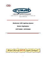
1. Attach the bracket to the bottom of the light using supplied hi-low
screws. See Figure 1.
Figure 1 Flat Surface Mount
#10 Hi-Low Screw
Bracket
Light
2. Using the bracket as a template, scribe the four (4) mounting hole
locations.

14
Permanently Mounting the HighLighter Elite
HighLighter® Elite
Federal Signal www.fedsig.com
DRILLING PRECAUTIONS: When drilling holes, check the area you
are drilling into to ensure that you do not damage vehicle components
while drilling. All drilled holes should be deburred, and all sharp edges
should be smoothed. All wire routings going through drilled holes
should be protected by a grommet or convolute/split loom tubing.
3. Drill an appropriately sized hole for the installer-supplied #10
hardware.
4. Refer to “Wiring the HighLighter Elite” on page 17 for wire
connections.
5. Plug the supplied connector into the bottom of the light. See Figure2.
Figure 2 Connecting the Light
6. Attach the light to the mounting surface using installer-suppled #10
hardware.

15
Permanently Mounting the HighLighter Elite
Installation, Operation, and Maintenance Instructions
Federal Signal www.fedsig.com
Attaching the Light to a Flat Bar
To permanently mount the HighLighter Elite to a flat bar:
1. Using the bracket as a template, scribe two (2) mounting hole
locations for the installer-supplied 1/4-20 carriage bolts.
DRILLING PRECAUTIONS: When drilling holes, check the area you
are drilling into to ensure that you do not damage vehicle components
while drilling. All drilled holes should be deburred, and all sharp edges
should be smoothed. All wire routings going through drilled holes
should be protected by a grommet or convolute/split loom tubing.
2. Drill two 17/64-inch holes at the scribed marks.
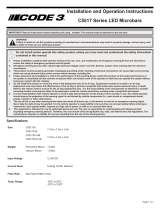
3. Load carriage bolts into the bracket and attach it to the bottom of the
light using the supplied hi-low screws. See Figure 3.
Figure 3 Bar Mount
#10 Hi-Low Screw
Installer-Supplied
1/4-20 Carriage
Bolts
Light

16
Permanently Mounting the HighLighter Elite
HighLighter® Elite
Federal Signal www.fedsig.com
4. Refer to “Wiring the HighLighter Elite” on page 17 for wire
connections.
5. Plug the supplied connector into the bottom of the light. See Figure 4.
Figure 4 Connecting the Light
6. Attach the light to the mounting surface using installer-suppled 1/4-20
carriage bolts and related hardware. See Figure 3 on page 15.

17
Wiring the HighLighter Elite
Installation, Operation, and Maintenance Instructions
Federal Signal www.fedsig.com
Wiring the HighLighter Elite
HIGH CURRENT DEVICE: A light system is a high current system.
In order for the system to function properly, a separate negative (–)
connection and positive (+) connection must be made. All negative
connections should be connected to the negative battery terminal,
and a 2 A fuse should be installed on the positive battery terminal
connection as close to the battery as possible. Ensure that all
wires and fuses are rated correctly to handle the system amperage
requirements.
The permanent mount HighLighter Elite is supplied with a
12-inch wire harness. The wires must be extended using installer-supplied
18AWG wire minimum and terminals.
Table 2 Wire Connections
Color Description Connection Point
Black Ground Battery Negative
Red Mode 1 Switched Positive
12-24 Vdc
White Mode 2 Switched Positive
12-24 Vdc
Brown Low Power/Mode 3 Switched Positive
12-24 Vdc
Green Program/FSLink™12-24 Vdc
To wire the HighLighter Elite:
1. Determine the required functions and the length of wires needed
to access them. A five-conductor cable can be selected for a full-
featured installation. For lengths up to 15 feet (5 m), use minimum
18AWG (1 mm) wire. For lengths over 15 feet, use minimum 16AWG
(1.5 mm) wire. Before wiring the device, refer to Table 2 for the
function of each wire.
2. Strip 1/4 inch (6 mm) of insulation from the ends of the installer-
supplied wires.
3. Use installer-supplied insulated butt connectors to connect the wires
to the Elite’s power cable. Ensure that the connectors are securely
crimped and properly insulated.

18
Conguring the HighLighter Elite
HighLighter® Elite
Federal Signal www.fedsig.com
4. Connect the end of the fuse holder to the positive (+) terminal of the
voltage source.
5. Connect the black (–) wire from the Elite to a known good vehicle
ground as close to the light as practical. The black wire is ground and
must be connected to a suitable chassis ground if it cannot be taken
directly to the negative terminal of the battery.
6. The green wire has two functions: It is the runner wire that
synchronizes FSLink™-Equipped products, and it serves as the
function/pattern programming wire.
7. The red wire powers the device in Mode 1 when connected to a
fused, positive voltage. Mode 1 is set to single/double/quad (pattern
no. 1) by default.
8. The white wire powers the device in Mode 2 when connected to
a fused, positive voltage. If Mode 1 is active, powering Mode 2 will
override Mode 1. Mode 2 is set to steady (pattern no. 10) by default.
9. The brown wire powers the device in Mode 3 when connected to a
fused, positive voltage. If Modes 1 or 2 are active, powering Mode 3
will override Modes 1 and 2. Mode 3 is set to cruise (pattern no. 7) by
default.
Conguring the HighLighter Elite
If the Elite’s operating functions are to be changed from the default,
perform the following steps.
NOTE: For models with an accessory plug instead of a wire harness, the
device can still be configured but has fewer options. The device only
has a Mode 1 switch (switch with LED) and a programming switch (blank
switch). When the steps below say to apply power to the green wire, press
the programming switch instead. Mode 2 and Mode 3 are not available.
Selecting a Flash Pattern
LIGHT HAZARD: This product contains a high-intensity LED device. To
prevent permanent eye damage, DO NOT stare into the light beam at
close range.

19
Conguring the HighLighter Elite
Installation, Operation, and Maintenance Instructions
Federal Signal www.fedsig.com
Selecting a flash pattern from the device’s internal library of flash patterns
is optional. It should be done during installation. For available flash
patterns, see Table 3 on page 22.
To select a flash pattern:
1. Select Mode 1 (red wire), Mode 2 (white wire), or Mode 3 (brown wire).
2. Apply power (+12-24 Vdc) to that wire.
3. To activate FSLink™, tap the green wire to + 12-24 Vdc until the desired
pattern is reached. For magnetically mounted lights, you can click the
momentary switch instead of tapping the green wire.
NOTE: When tapping the green wire to change patterns, do not hold
power for longer than one second, or other features of the device will
change.
Selecting Sync or Alt
When setting up devices to be synchronized, they must never be
operated without a ground connection. If a poor ground connection exists,
the unit will operate erratically and the warranty is voided. Routinely
inspect all connections to ensure that they are secure.
The device can synchronize with other Elites. It will either flash with or
alternate the timing of the flashes with other Elites. Select this feature
separately for Mode 1, Mode 2, or Mode 3.
To synchronize your selected flash pattern:
1. Activate Mode 1, 2, or 3.
2. Connect and hold the green wire to the positive voltage source until
the light pulses twice, and then release it. The light switches from its
initial setting to its opposite. “Flash with” becomes “Alternate,” or vice
versa.
3. To synchronize, after setup, connect the green wires together.
For this feature to operate, permanently connect all green wires after all
lights in the system are configured.

20
Conguring the HighLighter Elite
HighLighter® Elite
Federal Signal www.fedsig.com
Selecting Single- or Dual-Color (if equipped)
The device can be made to either flash a single color or two colors. This is
done separately for Mode 1, 2, or 3.
To select single- or dual-color:
1. Activate the mode for which this color feature is to be set.
2. Connect and hold the green wire to the power until the light pulses
three times, and then release it.
3. The device cycles between settings: primary Single-Color, secondary
Single-Color, and Dual-Color.
Selecting the Color Order
You can set the order in which a light flashes. The order is selected
separately for Mode 1, Mode 2, or Mode 3.
To select the color order:
1. Activate the Mode for which this color feature is to be set.
2. Hold the green wire to the positive voltage source until the light
pulses four times, and then release the wire. The device switches
color from the initial setting to its opposite. For example, a dual-color,
amber-red light set to flash amber then red will change to flashing red
then amber. A dual color, amber-red light set to the single color red
will become amber.
Selecting Dim Mode
The device can be made to function in Dim Mode. This can be set
separately for Mode 1, Mode 2, or Mode 3.
To activate Dim Mode:
1. Activate the Mode for which this feature is to be set.
2. Hold the green wire to the positive voltage source until the light
pulses six times, and then release the wire. The Mode switches from
its initial setting to its opposite. The normal setting becomes “Dim
Mode” and vice versa. Changing the pattern will reset the Dim Mode
to o.

21
Conguring the HighLighter Elite
Installation, Operation, and Maintenance Instructions
Federal Signal www.fedsig.com
Alternatively, Dim Mode can be activated on Mode 1 or 2 by setting Mode
3 to pattern 26 (Dim Mode) and simultaneously powering Mode 3 with
either Mode 1 or Mode 2.
NOTE: When pattern 10 (steady) is selected, the Dim Mode function will
cycle through three settings: normal, dim, and cruise.
Resetting the Device to the Default Settings
To reset the device to the default settings, apply power to the green wire
while Mode 1, Mode 2, or Mode 3 is powered. Hold the wire to the power
source until the light pulses seven times, and then remove power.
NOTE: No change occurs if you remove power from the green wire after
the seventh pulse finishes.

22
Conguring the HighLighter Elite
HighLighter® Elite
Federal Signal www.fedsig.com
Table 3 Flash Patterns
Flash
Pattern
No.
Description Flash Rate (FPM)
1* Single/Double/Quad 91
2 Split Quad 60
3Split Triple 85
4 Double Flash Left/Right-Front/
Back 84
5 Quad Flash Left/Right -Front/
Back 74
6 Rotate Counter Clockwise 180
7*** Cruise N/A
8 Random, Patterns #1-7 Various
9Random, Select Patterns #11-25 Various
10** Steady (fades to Dim) N/A
11 Single Flash 75
12 Single Flash 120
13 Double Flash 80
14 Double Flash 120
15 Triple Flash 80
16 Triple Flash 120
17 Quad Flash 60
18 Quad Flash 75
19 Quad Flash 95
20 Quad FedPulse 75
21 5x Flash 75
22 7x Flash 80
23 Single Flash/Quad Flash 120/60
24 Decelerating 60
25 Accelerating 60
26 Dim (only Mode 3) N/A
*Pattern 1 is the default setting for Mode 1.
**Pattern 10 is the default setting for Mode 2.
***Pattern 7 is the default setting for Mode 3.

23
Getting Technical Support
Installation, Operation, and Maintenance Instructions
Federal Signal www.fedsig.com
Getting Technical Support
For technical support, please contact:
Federal Signal Corporation
Phone: 1-800-433-9132
Email: [email protected]
Ordering Replacement Parts
To order replacement parts, call Customer Support at
1-800-264-3578, 7a.m. to 5 p.m., Monday through Friday (CT), or contact
your nearest distributor.
Table 4 Replacement Parts - Permanent Mount
Description Part No
Bracket 856003781
Power Plug/Screw Kit 77701391
Table 5 Replacement Parts - Suction Cup Magnet Mount
Description Part No
Suction Cup 862702694
Magnet 8550012
0.5-inch #8 Hi-Low Screw 70000900-08
0.188-inch Cable Clamp 8542A028-04
Power Plug 17502590
Table 6 Replacement Parts - Magnet Mount
Description Part No
Magnet 8550300
Mylar Magnet Cover 1611464
0.5-inch #10 Hi-Low Screw w/ Washer 70001392-08W
0.188-inch Cable Clamp 8542A028-04
0.5-inch #8 Hi-Low Screw 70000900-08
Power Plug 17502590

24
Getting Repair Service
HighLighter® Elite
Federal Signal www.fedsig.com
2645 Federal Signal Drive
University Park, Illinois 60484
www.fedsig.com
Customer Support
Police/Fire-EMS: 800-264-3578 • +1 708 534-3400
Work Truck: 800-824-0254 • +1 708 534-3400
Technical Support 800-433-9132 • +1 708 534-3400
Getting Repair Service
The Federal Signal factory provides technical assistance with any
problems that cannot be handled locally.
Any units returned to Federal Signal for service, inspection, or repair must
be accompanied by a Return Material Authorization (RMA). Obtain an RMA
from a Local Distributor or Manufacturer’s Representative. Provided a brief
explanation of the service requested or the nature of the malfunction.
Address all communications to the following address.
Federal Signal Corporation
Service Department
2645 Federal Signal Drive
University Park IL 60484-3167

25500775 SP
Rev A2 0123
© Copyright 2022-2023 Federal Signal Corporation
Instrucciones de instalación,
funcionamiento y mantenimiento
HighLighter® Elite

Garantía limitada
Este producto está sujeto y cubierto por una garantía limitada,
cuya copia se puede encontrar en www.fedsig.com/SSG-Warranty.
También se puede obtener una copia de esta garantía limitada si
se solicita por escrito a Federal Signal Corporation, 2645 Federal
Signal Drive, University Park, IL 60484, por correo electrónico a
[email protected] o por teléfono al +1 708-534-3400.
Esta garantía limitada sustituye a todas las demás garantías,
expresas o implícitas, contractuales o estatutarias, incluidas,
entre otras, la garantía de comerciabilidad, la garantía de
idoneidad para un n determinado y cualquier garantía contra el
incumplimiento de su nalidad esencial.
2645 Federal Signal Drive
University Park, Illinois 60484
www.fedsig.com
Servicio de Atención al Cliente
Policía/Bomberos-Servicios
Médicos de Emergencia: 800-264-3578 • +1 708 534-3400
Camión de trabajo: 800-824-0254 • +1 708 534-3400
Asistencia Técnica 800-433-9132 • +1 708 534-3400
Todas las marcas comerciales son propiedad de sus respectivos dueños.

27
Instrucciones de instalación, funcionamiento y mantenimiento
Federal Signal www.fedsig.com
Contenido
Mensaje de seguridad ......................................................................................28
Mensajes de seguridad ....................................................................................32
Introducción .......................................................................................................34
Desembalaje de la barra de luces ....................................................................34
Preparación para la instalación de la barra de luces .....................................34
Montaje magnético o mediante ventosa con imán.........................................36
Montaje jo del HighLighter Elite .....................................................................37
Cableado del HighLighter Elite ........................................................................42
Conguración de HighLighter Elite ................................................................. 43
Cómo obtener asistencia técnica ....................................................................48
Pedido de piezas de repuesto ..........................................................................48
Figuras
Figura 1 Montaje en una supercie plana ......................................................38
Figura 2 Conexión de la luz .............................................................................39
Figura 3 Montaje de la barra ............................................................................40
Figura 4 Conexión de la luz .............................................................................41
Tablas
Tabla 1 Contenido del kit .................................................................................34
Tabla 2 Conexiones de los cables ..................................................................42
Tabla 3 Patrones de destello ...........................................................................47
Tabla 4 Piezas de repuesto para el montaje jo ............................................48
Tabla 5 Piezas de repuesto para el montaje de ventosa con imán ..............48
Tabla 6 Piezas de repuesto para el montaje magnético ...............................48

28 HighLighter® LED Micro
Federal Signal www.fedsig.com
Mensaje de seguridad
Mensaje de seguridad
Mensaje de seguridad para los instaladores de equipos de luces de
advertencia
La vida de las personas depende de la correcta instalación
ymantenimiento de los productos de Federal Signal. Es importante leer
yseguir todas las instrucciones enviadas con este producto y el producto
original. Acontinuación, se enumeran otras instrucciones y precauciones
de seguridadimportantes que debe seguir:
Antes de la instalación o el mantenimiento
Calificaciones
• Para instalar o reparar correctamente este equipo, debe tener un
buenconocimiento de los procedimientos y sistemas mecánicos
yeléctricos de los automóviles, además de conocimientos sobre
la instalación y el mantenimiento de equipos de advertencia
de seguridad. Consulte siempre los manuales de servicio del
vehículocuando realice instalaciones de equipos en él.
Riesgos asociados a la iluminación
• Para ser un dispositivo de advertencia eficaz, este producto produce
una luz brillante que puede ser peligrosa para la vista cuando se mira
decerca. Si mira directamente a este producto de iluminación desde
unacorta distancia, puede sufrir daños permanentes en la vista.
• No instale el sistema de iluminación en una zona que pueda bloquear,
perjudicar o cegar la visión del conductor. Asegúrese de que el
sistema esté montado en una posición fuera del campo de visión del
conductor para que este pueda operar el vehículo de forma segura.
• Las fuentes de alimentación y los cabezales de luz de Federal
Signal están diseñados para funcionar juntos como un sistema.
Lacombinación de cabezales de luz y una fuente de alimentación
de diferentes fabricantes podría reducir la eficacia de la advertencia
del sistema de iluminación y dañar los componentes. Verifique o
pruebe la combinación para asegurarse de que el sistema funciona
correctamente y cumple con las normas o directrices federales,
estatales y locales.

29
Installation, Operation, and Maintenance Instructions
Federal Signal www.fedsig.com
Mensaje de seguridad
Riesgos eléctricos
• Un sistema de iluminación es un sistema de alta corriente. Para que el
sistema funcione correctamente, se debe realizar una conexión negativa
(-) y una conexión positiva (+) por separado. Todas las conexiones
negativas se deben conectar al terminal negativo de la batería y debe
instalarse un fusible adecuado en la conexión del terminal positivo de la
batería, lo más cerca posible a ella. Asegúrese de que todos los cables
yfusibles tienen la potencia nominal correcta para soportar los requisitos
de amperaje del dispositivo y del sistema.
• Nunca intente instalar un equipo de recambio que se conecte al
cableado del vehículo sin antes revisar su diagrama de cableado
provisto por el fabricante. Asegúrese de que la instalación no
afectará el funcionamiento del vehículo ni las funciones o circuitos de
seguridad obligatorios. Siempre compruebe el buen funcionamiento
del vehículo después de lainstalación.
• No monte una antena de radio a menos de 18pulgadas del sistema
de iluminación. Una colocación demasiado cercana al sistema podría
provocarle un mal funcionamiento o daños debido a las fuertes ondas
de radio. También podría ocasionar que el ruido de radio emitido por
el sistema de iluminación interfiera con la recepción del transmisor de
radio y la reduzca.
• No intente lavar este o cualquier otro dispositivo eléctrico mientras
esté conectado a su fuente de alimentación. La exposición a líquidos
mientras el producto está conectado a la fuente podría provocar una
descarga eléctrica y lesiones personales, además de ocasionar un
cortocircuito ydañar el producto.
Durante la instalación y el mantenimiento
• NO permita que caigan virutas de metal en el interior del producto.
Esto puede provocar el fallo del sistema. Si es necesario perforar
cerca de la unidad, coloque una cubierta aprobada por ESD sobre la
unidad. Inspeccione la unidad después del montaje para asegurarse
de que no haya virutas en la unidad o cerca de ella.
• Para evitar una explosión de la batería, primero desconecte el cable
negativo de la batería y vuelva a conectarlo al final. Evite provocar una
chispa al conectarlo a la batería o cerca de ella. Los gases producidos
porla batería pueden causar su explosión, lo que podría provocar
daños en el vehículo y lesiones graves.

30 HighLighter® LED Micro
Federal Signal www.fedsig.com
Mensaje de seguridad
• NO conecte este sistema a la batería del vehículo hasta que se
hayan realizado TODAS las demás conexiones eléctricas, se haya
completado el montaje de todos los componentes y se haya verificado
que no existencortocircuitos. Si el cableado está en cortocircuito
con la carrocería o la estructura del vehículo, los conductores de alta
corriente pueden provocar chispas peligrosas, lo que podría dar lugar
a incendios eléctricos o a la proyección de metal fundido.
• NO instale equipos ni coloque el cableado (o el cable de conexión)
demodo que interfiera con el sistema de un airbag.
• Si se retira temporalmente un asiento del vehículo, verifique con el
fabricante si es necesario recalibrar el asiento para un funcionamiento
correcto del airbag.
• Antes de montar cualquier componente, consulte el manual para
asegurarse de que el componente que va a instalar es adecuado
para su uso en esa zona del vehículo. Muchos componentes no están
diseñados para usarse en el compartimento del motor o en otras
zonas deexposición ambiental extrema.
• Cuando taladre en la estructura de un vehículo, asegúrese de
que ambos lados de la superficie no contengan elementos que se
puedan dañar. Elimine los rebordes de las perforaciones. Para evitar
cortocircuitos eléctricos, coloque un aislante en todos los orificios por
los que pase el cableado. Asegúrese de que los tornillos de montaje
no provoquen dañoseléctricos o mecánicos en el vehículo.
• Consulte la hoja de instrucciones que acompaña al sistema de
iluminaciónen la que encontrará las conexiones eléctricas correctas,
asícomo otras precauciones e información.
• Debido a que la estructura del techo del vehículo y las condiciones
de conducción varían, no conduzca un vehículo con una luz de
advertencia instalada magnéticamente. La luz podría desprenderse
del vehículo ycausar lesiones o daños. La reparación de los daños
ocasionados por ignorar esta advertencia será responsabilidad
exclusiva del usuario.
• Ubique los controles del sistema de luces de manera que el
VEHÍCULO y los CONTROLES se puedan operar con seguridad en
todas las condiciones de conducción.

31
Installation, Operation, and Maintenance Instructions
Federal Signal www.fedsig.com
Mensaje de seguridad
Después de la instalación o el mantenimiento
• Después de la instalación, pruebe el sistema de iluminación para
asegurarse de que funciona correctamente.
• Si se retira temporalmente un asiento, verifique con el fabricante
del vehículo si es necesario recalibrarlo para una correcta
implementacióndelairbag.
• Pruebe todas las funciones del vehículo, incluida la bocina,
lasfunciones de seguridad y los sistemas de luces, para asegurarse
de que funcionan correctamente. Asegúrese de que la instalación
no afectó el funcionamiento del vehículo ni modificó ninguna de sus
funciones ocircuitos de seguridad.
• Los reflectores, espejos o lentes rayados u opacos reducirán la
eficacia del sistema de iluminación. Evite ejercer una presión fuerte
y usar productos cáusticos o a base de petróleo cuando limpie el
sistema de iluminación. Sustituya los componentes ópticos que se
hayan rayado orajado durante la instalación del sistema.
• No intente activar o desactivar el control del sistema de iluminación
mientras conduce en una situación de peligro.
• Inspeccione con frecuencia el sistema para asegurarse de que
funciona correctamente y de que está bien sujeto al vehículo.
• Una vez finalizada la instalación y las pruebas, entregue una copia
de estas instrucciones tanto al personal de instrucción como al
deoperación.
• Guarde estas instrucciones en un lugar seguro y consúltelas cuando
realice el mantenimiento o reinstale el producto.
El incumplimiento de todas las precauciones e instrucciones de
seguridadpuede provocar daños materiales, lesiones graves o la muerte.
CONSERVE Y CONSULTE ESTOS MENSAJES

32 HighLighter® LED Micro
Federal Signal www.fedsig.com
Mensajes de seguridad
Mensajes de seguridad
Mensajes de seguridad para los operadores de equipos de luces de
advertencia
La vida de las personas depende del uso seguro de nuestros productos.
A continuación, se enumeran algunas instrucciones y precauciones de
seguridad importantes que debe seguir:
• Aunque su sistema de advertencia funcione correctamente, puede
que no sea completamente eficaz. Es posible que las personas no
vean o no presten atención a la señal de advertencia. Teniendo esto
en cuenta, debe continuar conduciendo con precaución.
• Puede ocurrir que la señal de advertencia sea obstruida por objetos
naturales o artificiales que se interpongan entre su vehículo y los
demás,como, por ejemplo, levantar el capó o la tapa del maletero.
Tengaespecial cuidado en este tipo de situaciones.
• Para ser un dispositivo de advertencia eficaz, este producto produce
una luz brillante que puede ser peligrosa para la vista cuando se mira
decerca. Si mira directamente a este producto de iluminación desde
unacorta distancia, puede sufrir daños permanentes en la vista.
• Es importante que entienda perfectamente cómo operar con
seguridad este sistema de advertencia antes de usarlo.
• Opere el vehículo y su sistema de luz/sonido de acuerdo con el
procedimiento operativo estándar de su departamento.
• Si una función seleccionada no funciona correctamente o si alguna
de lasluces permanece iluminada cuando el mando está apagado,
desconecte el conector de alimentación de la unidad de control
ycomuníquese con el centro de servicio más cercano.
• Al comienzo de su turno, asegúrese de que todo el sistema de
lucesdeadvertencia y el sistema de sirena estén bien fijados
yfuncionencorrectamente.
• El montaje con ventosas es solo para aplicaciones temporales.
Launidad se debe retirar de la ventana y guardar en un lugar
seguro cuando no se utilice. Los cambios de temperatura y la luz

33
Installation, Operation, and Maintenance Instructions
Federal Signal www.fedsig.com
Mensajes de seguridad
solar pueden hacer que las ventosas pierdan capacidad de succión.
Compruebe la unidad de forma periódica para asegurarse de que las
ventosas tienen un agarre firme en la superficie de montaje. Una luz
mal sujetada puede caerse del vehículo y causar lesiones o daños.
• La capacidad de sujeción de los sistemas de montaje magnético
depende del acabado y la planicidad de la superficie, así como
del grosor de la superficie de montaje de acero. Por lo tanto, para
propiciar un montaje magnético adecuado realice lo siguiente:
• Mantenga la superficie y los imanes limpios, secos y sin
partículas extrañas que impidan un buen contacto con
lasuperficie.
• Asegúrese de que la superficie de montaje sea plana.
• No utilice un sistema de montaje magnético en vehículos
contechos de vinilo.
El incumplimiento de estas precauciones puede provocar daños
materiales, lesiones graves o la muerte.
CONSERVE Y CONSULTE ESTOS MENSAJES

34 HighLighter® LED Micro
Federal Signal www.fedsig.com
Introducción
Introducción
El HighLighter® Elite es una luz de advertencia con tecnología LED que
ocupa poco espacio y tiene un consumo de corriente bajo. La luz está
disponible en uno de los tres tipos de montaje: Fijo, ventosa con imán
o imán. La luz tiene tres modos de funcionamiento, 25 patrones de luz
seleccionables yunafunción opcional de bajo consumo.
Desembalaje de la barra de luces
Después de sacar la luz del embalaje, inspeccione si ha sufrido daños
duranteel transporte. Si está dañada, no intente instalarla ni utilizarla.
Presenteinmediatamente un reclamo al transportista, en el que se
indiquen los daños sufridos. Compruebe minuciosamente todos los
sobres, etiquetas deenvío y etiquetas antes de retirarlos o destruirlos.
Asegúrese de que las piezas enumeradas en la Tabla 1 están incluidas
en el paquete. Si le falta alguna pieza, comuníquese con el Servicio de
Atención al Cliente al
1-800-264-3578, de 7 a 17horas, de lunes a viernes (CT).
Tabla 1 Contenido del kit
Fijo Ventosa con imán Imán
Cantidad Descripción Cantidad Descripción Cantidad Descripción
1 Mini barra de
luces 1 Mini barra de
luces 1 Mini barra de
luces
1 Soporte de
montaje 1 Tarjeta con
mensaje de
seguridad
4 Pegatinas
de protección
1 Mazo de cables 1 Tarjeta con
mensaje de
seguridad
4 Tornillos Hi-Low
n.º 10
1 Tarjeta con
mensaje de
seguridad
Preparación para la instalación de la barra de luces
Determinación de la ubicación de montaje y del enrutamiento
de cables
La siguiente sección solo cubre el montaje y el enrutamiento de los
cables. Para obtener instrucciones sobre las conexiones de cableado,
consulte"Cableado del HighLighter Elite" on page 42.

35
Installation, Operation, and Maintenance Instructions
Federal Signal www.fedsig.com
Preparación para la instalación de la barra de luces
Antes de la instalación realice lo siguiente:
• Asegúrese de que la tensión de la batería es la misma que la de la
barra de luces.
• Compruebe que la barra de luces y las piezas de montaje se ajustan
alvehículo.
• Determine en qué lugar del vehículo montará la barra de luces.
UBICACIÓN DE LOS CONTROLES DEL OPERADOR: Los controles del
sistema de luces deben estar ubicados de manera que el VEHÍCULO
y los CONTROLES se puedan operar con seguridad en todas las
condiciones de conducción.
SISTEMA DE AIRBAG: No instale equipos ni coloque el cableado de
modo que interera con el sistema de un airbag. El incumplimiento de
esta advertencia reducirá la ecacia del airbag o podría desprender el
equipo y causar lesiones graves o la muerte.
• Decida dónde colocar el cableado alrededor de las zonas del airbag.
• Decida dónde colocar los cables de alimentación y de conexión
atierra de la barra de luces.
PRECAUCIÓN AL RETIRAR EL ASIENTO: Si se retira temporalmente
un asiento del vehículo, verique con el fabricante si es necesario
recalibrar el asiento para un funcionamiento correcto del airbag.
El incumplimiento de esta advertencia puede causar lesiones graves
o la muerte.
• Para facilitar el cableado, retire los asientos y el neumático de
repuesto, y,de ser necesario, el revestimiento del techo.
• Separe todo el cableado del equipo electrónico del cableado del
equipo de radio bidireccional.

36 HighLighter® LED Micro
Federal Signal www.fedsig.com
Montaje magnético o mediante ventosa con imán
PRECAUCIONES DURANTE LA INSTALACIÓN: El sistema de
advertencia o el sistema de radio bidireccional podrían fallar si se
instala una antena de radio bidireccional sobre la barra de luces
o a menos de 18 pulgadas de ella. Antes de instalar la barra de
luces o una antena de radio bidireccional de forma permanente,
pruebe el sistema de advertencia y el sistema de radio bidireccional.
Algunas instalaciones pueden requerir la reubicación de la antena en el
maletero o en el guardabarros. NO perfore la barra de luces ni le instale
dispositivos auxiliares, ya que el sistema de advertencia podría fallar.
• Para evitar interferencias, mantenga las antenas de la radio
bidireccionalaun mínimo de 18pulgadas (45,7cm) de distancia del
equipo deadvertencia.
• Siempre que sea posible, utilice la longitud total de los cables. NO una
loscables.
• No enrolle el exceso de cable. Deje un circuito cerrado de drenaje
para el mantenimiento de la barra de luces.
• Después de realizar las perforaciones para los cables, elimine los
rebordes alisando las partes afiladas e inserte aislantes para proteger
los cables de los roces.
• Cuando conecte el equipo a tierra, utilice los puntos de conexión
atierra en el vehículo suministrados por el fabricante.
IMPORTANTE: Después de la instalación, inspeccione con frecuencia la
barra de luces y las bases de montaje para asegurarse de que todas las
sujeciones y los soportes están ajustados.
Montaje magnético o mediante ventosa con imán
NO CONDUZCA CON UNA LUZ DE ADVERTENCIA MONTADA DE
FORMA MAGNÉTICA: Debido a que la estructura del techo del vehículo
y las condiciones de conducción varían, no conduzca un vehículo
con una luz de advertencia instalada magnéticamente. La luz podría
desprenderse del vehículo y causar lesiones o daños. La reparación
de los daños ocasionados por ignorar esta advertencia será
responsabilidad exclusiva del usuario.

37
Installation, Operation, and Maintenance Instructions
Federal Signal www.fedsig.com
Montaje jo del HighLighter Elite
MONTAJE MAGNÉTICO ADECUADO: La capacidad de sujeción de los
sistemas de montaje magnético depende del acabado y la planicidad
de la supercie, así como del grosor de la supercie de montaje de
acero. Por lo tanto, para propiciar un montaje magnético adecuado
realice lo siguiente:
• Mantenga la supercie de montaje y los imanes limpios,
secos y libres de partículas extrañas que impidan un buen
contacto con la supercie.
• Asegúrese de que la supercie de montaje sea plana.
• No utilice un sistema de montaje magnético en vehículos con
techos de vinilo.
Para montar el HighLighter Elite:
1. Coloque el conjunto de la barra de luces en el techo del vehículo
en un lugar que proporcione la máxima eficacia de señalización de
acuerdo conla finalidad.
2. Para los modelos con ventosas, elimine el aire retenido aplicando
presiónhacia abajo en la parte superior de la cúpula mientras tira
hacia arriba de las lengüetas de liberación.
3. Para hacer funcionar el conjunto de la barra de luces con imán o con
ventosa, inserte el enchufe del extremo del conjunto de cables en la
toma de corriente para accesorios. Encienda y apague la ficha con el
interruptor de encendido de esta. Se prenderá una luz piloto cuando la
alimentación esté conectada.
4. Para retirar los modelos con ventosas, tire hacia arriba de las
lengüetas de liberación mientras levanta la barra de luces.
Montaje jo del HighLighter Elite
Utilice el soporte de montaje fijo suministrado para montar la luz en
una superficie plana o en un barral plano con las piezas provistas por
elinstalador.
Fijación de la luz a una supercie plana
Para montar de forma permanente el HighLighterElite en una superficie
plana realice lo siguiente:
1. Fije el soporte a la parte inferior de la luz con los tornillos
suministrados. Vea la Figura 1.

38 HighLighter® LED Micro
Federal Signal www.fedsig.com
Montaje jo del HighLighter Elite
Figura 1 Montaje en una supercie plana
#10 Hi-Low Screw
Bracket
Light
2. Con el soporte como plantilla, trace las cuatro (4) ubicaciones de los
orificios de montaje.
PRECAUCIONES AL PERFORAR: Al realizar los oricios, compruebe
la zona para asegurarse de no dañar los componentes del vehículo
mientras perfora. Se deben remover los rebordes de todas la
perforaciones alisando las partes aladas. Todos los cables que
pasen por los agujeros taladrados deben estar protegidos por un
aislante o por un caño de conexión.
3. Realice un orificio del tamaño adecuado para las piezas n.º 10
suministradas por el instalador.
4. Consulte "Cableado del HighLighter Elite" on page 42 para ver las
conexiones de los cables.
5. Enchufe el conector suministrado en la parte inferior de la luz. Vea la
Figura 2.

39
Installation, Operation, and Maintenance Instructions
Federal Signal www.fedsig.com
Montaje jo del HighLighter Elite
Figura 2 Conexión de la luz
6. Fije la luz a la superficie de montaje con las piezas n.º 10
suministradas por el instalador.
Fijación de la luz a un barral plano
Para montar HighLighter Elite a un barral plano de forma permanente
realice lo siguiente:
1. Con el soporte como plantilla, trace dos (2) ubicaciones donde
realizará los orificios de montaje para los pernos para carrocería de
1/4-20 suministrados por el instalador.
PRECAUCIONES AL PERFORAR: Al realizar los oricios, compruebe
la zona para asegurarse de no dañar los componentes del vehículo
mientras perfora. Se deben remover los rebordes de todas la
perforaciones alisando las partes aladas. Todos los cables que pasen
por los agujeros taladrados deben estar protegidos por un aislante
o por un caño de conexión.

40 HighLighter® LED Micro
Federal Signal www.fedsig.com
Montaje jo del HighLighter Elite
2. Realice dos orificios de 17/64pulgadas en las marcas trazadas.
3. Coloque los pernos para carrocería en el soporte y fíjelo a la parte
inferior de la luz con los tornillos suministrados. Vea la Figura 3.
Figura 3 Montaje de la barra
#10 Hi-Low Screw
Installer-Supplied
1/4-20 Carriage
Bolts
Light
4. Consulte "Cableado del HighLighter Elite" on page 42 para ver las
conexiones de los cables.
5. Enchufe el conector suministrado en la parte inferior de la luz. Vea la
Figura 4.

41
Installation, Operation, and Maintenance Instructions
Federal Signal www.fedsig.com
Montaje jo del HighLighter Elite
Figura 4 Conexión de la luz
6. Fije la luz a la superficie de montaje con los pernos para carrocería
1/4-20 y las piezas correspondientes suministrados por el instalador.
Veala Figura 3 en page 40.

42 HighLighter® LED Micro
Federal Signal www.fedsig.com
Cableado del HighLighter Elite
Cableado del HighLighter Elite
DISPOSITIVO DE ALTA CORRIENTE: un sistema de iluminación es un
sistema de alta corriente. Para que el sistema funcione correctamente,
se debe realizar una conexión negativa (-) y una conexión positiva
(+) por separado. Todas las conexiones negativas se deben conectar
al terminal negativo de la batería, y se debe instalar un fusible de 2 A
en la conexión del terminal positivo de la batería, lo más cerca de
ella posible. Asegúrese de que todos los cables y fusibles tienen la
potencia nominal correcta para soportar los requisitos de amperaje
del sistema.
El HighLighter Elite de montaje fijo trae un mazo de cables de
12pulgadas. Estos se deben extender con cables yterminales de 18AWG
suministrados por el instalador.
Tabla 2 Conexiones de los cables
Color Descripción Punto de
conexión
Negro Conexión a tierra Negativo de la
batería
Rojo Modo 1 Positivo conmutado
12-24 Vdc
Blanco Modo 2 Positivo conmutado
12-24 Vdc
Marrón Baja potencia/Modo
3Positivo conmutado
12-24 Vdc
Verde Programa/FSLink™12-24 Vdc
Para cablear HighLighter Elite realice lo siguiente:
1. Determine las funciones requeridas y la longitud de los cables
necesarios para acceder a ellas. Se puede seleccionar un cable de
cinco conductores para una instalación con todas las funciones.
Paralongitudes de hasta 15pies (5m), utilice un cable mínimo
de 18AWG(1mm). Para longitudes superiores a 15pies, utilice un
cable mínimo de 16AWG (1,5mm). Antes de cablear el dispositivo,
consultelaTabla 2 paraconocer la función de cada cable.
2. Pele 1/4 de pulgada (6mm) de aislamiento de los extremos de los
cables suministrados por el instalador.

43
Installation, Operation, and Maintenance Instructions
Federal Signal www.fedsig.com
Conguración de HighLighter Elite
3. Utilice los conectores a tope aislados suministrados por el instalador
paraconectar los cables al cable de alimentación de Elite. Asegúrese
de que los conectores estén bien prensados y correctamente
aislados.
4. Conecte el extremo del portafusibles al terminal positivo (+) de la
fuente de tensión.
5. Conecte el cable negro (-) de Elite a una conexión a tierra verificada
del vehículo lo más cerca de la luz posible. El cable negro es una
conexión a tierra, por lo que se debe conectar a una conexión a tierra
del chasis adecuada si no se puede llevar directamente al terminal
negativo de labatería.
6. El cable verde tiene dos funciones: es el cable de conexión que
sincroniza los productos equipados con FSLink™, y sirve como cable
deprogramación de funciones/patrones.
7. El cable rojo alimenta el dispositivo en Modo 1 cuando está conectado
auna tensión positiva con fusible. El Modo 1 está configurado por
defectocomo simple/doble/cuádruple (patrón n.º1).
8. El cable blanco alimenta el dispositivo en el Modo 2 cuando está
conectado a una tensión positiva con fusible. Si el Modo 1 está activo,
la alimentación del Modo 2 lo anulará. El Modo 2 está configurado
por defecto como regular (patrón n.º10).
9. El cable marrón alimenta el dispositivo en el Modo 3 cuando está
conectado a una tensión positiva con fusible. Si los Modos 1 o 2
están activos, la potencia del Modo 3 los anulará. El Modo 3 está
configurado por defecto como continuo (patrón n.º7).
Conguración de HighLighter Elite
Si las funciones de operación predeterminadas de Elite se deben cambiar,
realice los siguientes pasos.
NOTA: Para los modelos con un enchufe de accesorios en lugar de un
arnés de cables, el dispositivo aún se puede configurar pero tiene menos
opciones. El dispositivo solo tiene un interruptor de Modo 1 (interruptor
con LED) y un interruptor de programación (interruptor en blanco).
Cuando los pasos a continuación indiquen aplicar energía al cable verde,
presione el interruptor de programación en su lugar. El Modo 2 y el
Modo3 no están disponibles.

44 HighLighter® LED Micro
Federal Signal www.fedsig.com
Conguración de HighLighter Elite
Selección de un patrón de destello
RIESGO ASOCIADO A LA ILUMINACIÓN: Este producto contiene un
dispositivo LED de alta intensidad. Para evitar daños permanentes en
los ojos, NO mire jamente hacia el haz de luz a corta distancia.
La selección de un patrón de destello de la biblioteca interna de patrones
de destello del dispositivo es opcional. Se debe realizar durante la
instalación. Para conocer los patrones de destello disponibles, consulte la
Tabla 3 en page 47.
Para seleccionar un patrón de destello realice lo siguiente:
1. Seleccione el Modo 1 (cable rojo), el Modo 2 (cable blanco) o el Modo
3 (cable marrón).
2. Alimente (+12-24Vdc) ese cable.
3. Para activar el FSLink™, ponga en contacto el cable verde con
+12-24Vdc hasta alcanzar el patrón deseado. Para las luces montadas
magnéticamente, puede pulsar el interruptor de acción momentánea
enlugar de utilizar el cable verde.
NOTA: Cuando utilice el cable verde para cambiar los patrones, nohaga
correr energía durante más de un segundo, o se modificarán otras
características del dispositivo.
Selección de sincronización o alternancia
Nunca opere los dispositivos sin una conexión a tierra cuando configura
su sincronización. Si la conexión a tierra es inestable, la unidad
funcionará de forma errática y la garantía quedará anulada. Inspeccione
rutinariamente todas las conexiones para asegurarse de que son seguras.
El dispositivo se puede sincronizar con otros Elite. Puede sincronizar
los destellos con otros Elite o alternará la distribución de los parpadeos.
Seleccione esta función por separado para el Modo 1, el Modo 2 o el
Modo 3.
Para sincronizar el patrón de destello seleccionado realice lo siguiente:
1. Active el Modo 1, 2 o 3.

45
Installation, Operation, and Maintenance Instructions
Federal Signal www.fedsig.com
Conguración de HighLighter Elite
2. Conecte el cable verde a la fuente de tensión positiva y manténgalo
hasta que la luz parpadee dos veces; a continuación, retírelo. La luz
cambia de su ajuste inicial a su opuesto. “Destello sincronizado”
(Flashwith) pasa a “Alternado” (Alternate), o viceversa.
3. Para sincronizar, después de la configuración, conecte los cables
verdesentre sí.
Para que esta característica funcione, fije todos los cables verdes
después deconfigurar todas las luces del sistema.
Selección de uno o dos colores (si se incluye)
El dispositivo se puede configurar para que emita un destello de un solo
coloro de dos colores. Esto se configura por separado para el Modo 1, 2
o 3.
Para seleccionar un solo color o dos colores realice lo siguiente:
1. Active el Modo para el que se va a configurar esta función de color.
2. Conecte el cable verde a la fuente alimentación y manténgalo hasta
que la luz parpadee tres veces; a continuación, retírelo.
3. El aparato alterna entre los ajustes: monocolor primario,
monocolorsecundario y bicolor.
Selección del orden de los colores
Puede establecer el orden de los destellos de una luz. Se selecciona por
separado para el Modo 1, el Modo 2 o el Modo 3.
Para seleccionar el orden de los colores realice lo siguiente:
1. Active el Modo para el que se va a configurar esta función de color.
2. Mantenga el cable verde en la fuente de tensión positiva hasta que
laluzparpadee cuatro veces y luego retírelo. El dispositivo cambia
elcolor del ajuste inicial a su opuesto. Por ejemplo, una luz bicolor
ámbar-roja configurada para parpadear en ámbar y luego en rojo
cambiará a parpadear en rojo y luego en ámbar. Una luz bicolor
ámbar-roja configurada en el color único rojo se convertirá en ámbar.

46 HighLighter® LED Micro
Federal Signal www.fedsig.com
Conguración de HighLighter Elite
Selección del modo de atenuación
El dispositivo puede funcionar en Modo de atenuación. Se puede
configurar por separado para el Modo 1, el Modo 2 o el Modo 3.
Para activar el Modo de atenuación:
1. Active el Modo para el que se va a configurar esta función.
2. Mantenga el cable verde en la fuente de tensión positiva hasta que la
luzparpadee seis veces y luego retírelo. El Modo cambia de su ajuste
inicial a su opuesto. El ajuste normal pasa a “Modo de atenuación”
(Dim Mode), y viceversa. El cambio del patrón desactiva el modo
deatenuación.
A su vez, el Modo de atenuación puede activarse en el Modo 1 o 2
ajustandoel Modo 3 al patrón 26 (Modo de atenuación) y, al mismo
tiempo,alimentar este modo con el Modo 1 o el Modo 2.
NOTA: Cuando se selecciona el patrón 10 (regular), la función de Modo de
atenuación pasará por tres ajustes: normal, atenuado y continuo.
Restablecer la conguración predeterminada del dispositivo
Para restablecer la configuración predeterminada del dispositivo,
conecte el cable verde mientras el Modo 1, el Modo 2 o el Modo 3 están
encendidos. Mantenga el cable en la fuente de alimentación hasta que la
luz parpadee siete veces y, a continuación, retírelo.
NOTA: No se produce ningún cambio si retira el cable verde de la fuente
de alimentación después de que termine el séptimo parpadeo.

47
Installation, Operation, and Maintenance Instructions
Federal Signal www.fedsig.com
Conguración de HighLighter Elite
Tabla 3 Patrones de destello
Patrón de
destello n.º Descripción Velocidad de
destello (FPM)
1* Simple/Doble/Cuádruple 91
2 Cuádruple dividido 60
3 Triple dividido 85
4 Destello doble izquierda/
derecha-frente/atrás 84
5 Destello cuádruple izquierda/
derecha-frente/atrás 74
6 Girar en sentido antihorario 180
7*** Continuo N/A
8 Aleatorio, patrones del n.º 1 al 7 Varios
9 Aleatorio, patrones del
n.º 11 al 25 Varios
10** Regular (se atenúa) N/A
11 Destello único 75
12 Destello único 120
13 Destello doble 80
14 Destello doble 120
15 Destello triple 80
16 Destello triple 120
17 Destello cuádruple 60
18 Destello cuádruple 75
19 Destello cuádruple 95
20 Cuádruple FedPulse 75
21 Destello quíntuple 75
22 Siete destellos 80
23 Destello único/Dostello
cuádruple 120/60
24 Desaceleración 60
25 Aceleración 60
26 Atenuación (solo en Modo 3) N/A
*El patrón 1 es el ajuste por defecto para el Modo 1.
**El patrón 10 es el ajuste por defecto para el Modo 2.
***El patrón 7 es el ajuste por defecto para el Modo 3.

48 HighLighter® LED Micro
Federal Signal www.fedsig.com
Cómo obtener asistencia técnica
Cómo obtener asistencia técnica
Para obtener asistencia técnica, comuníquese con:
Federal Signal Corporation
Teléfono: 1-800-433-9132
Correo electrónico: [email protected]
Pedido de piezas de repuesto
Para pedir piezas de repuesto, llame al Servicio de Atención al Cliente al
1-800-264-3578, de 7 a 17horas, de lunes a viernes (CT), o comuníquese
consu distribuidor más cercano.
Tabla 4 Piezas de repuesto para el montaje jo
Descripción N.º de pieza
Soporte 856003781
Enchufe de alimentación/kit de
tornillos 77701391
Tabla 5 Piezas de repuesto para el montaje de ventosa con imán
Descripción N.º de pieza
Ventosa 862702694
Imán 8550012
Tornillo Hi-Low n.º 8 de 0,5 pulgadas 70000900-08
Abrazadera para cable de
0,188 pulgadas 8542A028-04
Enchufe de alimentación 17502590
Tabla 6 Piezas de repuesto para el montaje magnético
Descripción N.º de pieza
Imán 8550300
Cubierta magnética de Mylar 1611464
Tornillo Hi-Low n.º 10 de 0,5 pulgadas
con arandela 70001392-08W
Abrazadera para cable de
0,188 pulgadas 8542A028-04
Tornillo Hi-Low n.º 8 de 0,5 pulgadas 70000900-08
Enchufe de alimentación 17502590
/