Federal Signal ICON Snow Plow Light Manual de usuario
- Tipo
- Manual de usuario

Safety Messages for Installers of Warning Light Equipment
People’s lives depend on your safe installation of our products. It is important to read, understand
and follow all instructions shipped with the products. Listed below are some other important safety
instructions and precautions you should follow:
• To properly install this light, you must have a good understanding of automotive electrical procedures
and systems, along with proficiency in the installation and use of safety warning equipment.
• Do not install equipment or route wiring in the deployment path of an airbag.
• If a vehicle seat is temporarily removed, verify with the vehicle manufacturer if the seat needs to be
recalibrated for proper airbag deployment.
• When drilling into a vehicle structure, ensure that both sides of the surface are clear of anything that
could be damaged.
• Locate the light control so the VEHICLE and CONTROL can be operated safely under all driving
conditions.
• Do not attempt to activate or deactivate the light control while driving in a hazardous situation.
• Frequently inspect the light to ensure that it is operating properly and that it is securely attached to
the vehicle.
• This product contains high-intensity LEDs. Do not stare directly into the lights at a close range, or
permanent damage to your eyesight may occur.
• Refer to the instructions packed with related products for additional precautions and information.
• File these instructions in a safe place and refer to them when maintaining and/or reinstalling the
product.
Failure to follow all safety precautions and instructions may result in property damage, serious injury, or
death.
Introduction
This publication has instructions for installing the Federal Signal ICON Series Model ICSSPL-P LED
and replacement ICSSPL-P PASS / ICSSPL-P DRV Snow Plow Headlights. The light has stainless
steel brackets and hardware that permit vertical adjustment. Adapter cables (sold separately) can be
purchased to directly plug into select existing snow plow systems.
Unpacking the Product
After unpacking the product, inspect it for damage that may have occurred in transit. If it has been
damaged, do not attempt to install or operate it. File a claim immediately with the carrier, stating the
extent of the damage. Failure to identify damage before installation could lead to the rejection of any
claim. Carefully check all envelopes, shipping labels, and tags before removing or destroying them.
Ensure that the parts listed in Table1 or 2 are included in the package. If you are missing any parts,
contact Federal Signal Customer Support at 1-800-264-3578, 7 a.m. to 5 p.m., Monday through Friday
(CT).
25500794 Rev A4 1023
Installing the ICON Series ICSSPL-P
Snow Plow Headlight

Installing the ICON Series ICSSPL-P Snow Plow Headlight
2ICON Series ICSSPL-P Snow Plow Headlight
Federal Signal worktruck.fedsig.com
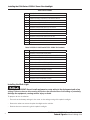
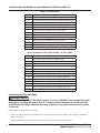
Table 1 Kit Contents
Qty Description
2 Stainless Steel Post Bracket, Black
2 Rubber Mounting Gasket for Post Bracket, Black
4 Stainless Steel Post Base, Black
4 Rubber Mounting Gasket for Post Base, Black
4 Stainless Steel Domed Friction Washer
4 Stainless Steel Screw, M12 1.75 X 70 mm
4 Stainless Steel Washer, for M12
4 Stainless Steel Lockwasher, for M12
4 Stainless Steel Nut, M12 1.75
4 Stainless Steel Screw, M8 1.25 X 25 mm
4 Stainless Steel Washer, for M8
4 Stainless Steel Lockwasher, for M8
1 Pigtail Connector
Table 2 ICSSPL-P PASS and ICSSPL-P DRV Kit Contents
Qty Description
1 Stainless Steel Post Bracket, Black
1 Rubber Mounting Gasket for Post Bracket, Black
2 Stainless Steel Post Base, Black
2 Rubber Mounting Gasket for Post Base, Black
2 Stainless Steel Domed Friction Washer
2 Stainless Steel Screw, M12 1.75 X 70 mm
2 Stainless Steel Washer, for M12
2 Stainless Steel Lockwasher, for M12
2 Stainless Steel Nut, M12 1.75
2 Stainless Steel Screw, M8 1.25 X 25 mm
2 Stainless Steel Washer, for M8
2 Stainless Steel Lockwasher, for M8
1 Pigtail Connector
Installing the Work Light
AIRBAG DEPLOYMENT: Do not install equipment or route wiring in the deployment path of an
airbag. Failure to observe this warning will reduce the eectiveness of the airbag or potentially
dislodge the equipment, causing serious injury or death.
To prepare for the installation:
• Ensure that the battery voltage is the same as the voltage rating of the plow headlight.
• Determine where to mount the plow headlight on the vehicle.
• Decide where to route wiring for the plow headlight.

Installing the ICON Series ICSSPL-P Snow Plow Headlight
3
ICON Series ICSSPL-P Snow Plow Headlight
Federal Signal worktruck.fedsig.com
To install the work light:
1. Determine the mounting location for the light and the installer-supplied control system.
DRILLING PRECAUTIONS: When drilling holes, check the area you are drilling into to ensure
that you do not damage vehicle components. All drilled holes should be deburred, and all sharp
edges should be smoothed. All wire routings going through drilled holes should be protected by
a grommet or convolute/split loom tubing.
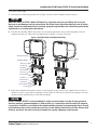
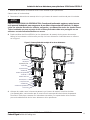
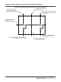
2. Drill two 12-millimeter (15/32-inch) holes at the mounting locations for the mounting bolts. Use the
supplied hardware to secure the headlights to the vehicle as shown in Figure 1.
Figure 1 Exploded View of Headlight Mounting
Bracket for Gasket
M12 Screw
Post Bracket
M6 Washer
M6 Lockwasher
M6 Screw
Friction Washer
Post Base
Gasket for Base
M12 Washer
M12 Lockwasher
M12 Nut
Passenger Headlight
Driver Headlight
3. Route wires between the power source and the control system. Install user-supplied fuses and fuse
holders as close as possible to the power source. Refer to Table 3 for minimum wire gauges and fuse
ratings for each wire/function on the plow headlight.
HIGH CURRENT DEVICE: A plow headlight is a high current system. In order for the system to
function properly, separate negative (-) and positive (+) connections must be made. All negative
connections should be connected to the negative battery terminal, and appropriate fuses should
be installed on the positive connections as close to the battery terminal as possible. Ensure that
all wires and fuses are rated correctly to handle the system amperage requirements.

Installing the ICON Series ICSSPL-P Snow Plow Headlight
4ICON Series ICSSPL-P Snow Plow Headlight
Federal Signal worktruck.fedsig.com
Table 3 Wiring and Functions
Wire Color Wire Function Recommended
Minimum Gauge Recommended Fuse
at 12 Vdc
Red High Beam (+) 16 AWG 10 A each; 20 A paired
Yellow Low Beam (+) 18 AWG 5 A each; 10 A paired
Green Turn Signal Lights (+) 22 AWG 1 A each
Grey Parking Light (+) 22 AWG 1 A each; 1 A paired
Black Ground (-) 16 AWG -
CHECK WIRING POLARITY: This device is only intended to have a common ground and be
switched on the positive voltage connections. Some vehicles are wired to have a common
positive voltage and be switched on the ground connections. If this device is connected in
reverse polarity, permanent damage may occur and render the device inoperable.
4. Route wire from the control system to the location of the plow headlight. Refer to Table 3 for
minimum wire gauges for each wire/function of the plow headlight.
5. Route a 16 AWG wire from the installation area of the light to an appropriate ground.
LIGHT HAZARD: A plow headlight produces bright light that can be hazardous to your eyesight
when viewed at a close range. Do not stare directly into the lights at a close range, or permanent
damage to your eyesight may occur.
6. Check the wiring and test the light for proper operation.
Aiming the Headlight
FEDERAL REGULATIONS: The installer of these snowplow headlights must certify that
installation conforms to applicable Federal Motor Vehicle Safety Standards as well as relevant
state and local laws. The headlights must be inspected for conformance if they are ever shifted/
adjusted.
After the headlight has been mounted and the electrical connections have been secured and tested, the
headlight will need to be aimed to comply with appropriate federal, state, and local standards.
1. Park the vehicle on a level surface so that the headlights are 25 feet in front of a flat, matte-white
surface, such as a wall or garage door. The surface should be perpendicular to both the ground and
to the vehicle center line.
2. The vehicle should be equipped for typical operation. The snow plow blade should be in place and in
the raised position.
3. The notes listed below are recommended for inspection by the Society of Automotive Engineers
(SAE) prior to setting or adjusting the headlight aim:
• Remove ice or mud from under the fenders.
• Set tire inflation pressures to the values specified on the vehicle information label.
• Check the vehicle springs for sag or broken leaves.

Installing the ICON Series ICSSPL-P Snow Plow Headlight
5
ICON Series ICSSPL-P Snow Plow Headlight
Federal Signal worktruck.fedsig.com
• Verify that there is no load in the vehicle other than the driver and spare tire kit.
• Check the functioning of any automatic vehicle leveling systems.
• Clean the head lamp lenses and check for the burnout of any light sources.
• Stabilize the suspension by rocking the vehicle sideways.
4. Verify that the headlight is at least 22 inches above the ground and not more than 54 inches above
the ground.
5. Mark or tape the vertical center line of the ICSSPL-P headlights and the vertical center line of the
vehicle on the white surface. Mark the horizontal center line of the headlights on the surface as well.
These markings should be measured from the physical headlights, not the light emitted from the
headlights.
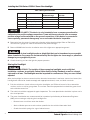
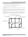
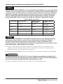
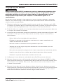
6. Power on the low beams of the headlights. Re-aim the headlights so that the top edge of the high-
intensity zone is aligned to the horizontal center line marking, and the left edge of the high-intensity
zone is aligned to the vertical center line marking for the respective headlight. See Figure 2 for
reference.
Figure 2 Headlight Aiming Procedure
Screen 25' from
plow headlights
Marking for vertical
center line of vehicle
Marking for vertical center line
of passenger plow headlight
Marking for vertical center line
of driver plow headlight
High-intensity zone of
passenger plow headlight
High-intensity zone of
driver plow headlight
Marking for horizontal
center line of plow headlights

Installing the ICON Series ICSSPL-P Snow Plow Headlight
6ICON Series ICSSPL-P Snow Plow Headlight
Federal Signal worktruck.fedsig.com
Getting Technical Support
For technical support, please contact:
Federal Signal Corporation
Service Department
Phone: 1-800-433-9132
Email: [email protected]
Getting Repair Service
The Federal Signal factory provides technical assistance with any problems that cannot be handled
locally. Any product returned to Federal Signal for service, inspection, or repair must be accompanied
by a Return Material Authorization (RMA). Obtain an RMA from a local Distributor or Manufacturer’s
Representative. Provide a brief explanation of the service requested or the nature of the malfunction.
Address all communications and shipments to the following:
Federal Signal Corporation
Service Department
2645 Federal Signal Dr.
University Park, IL 60484-3167
Ordering Replacement Parts
To order replacement parts, call Customer Support at 1-800-264-3578, 7 a.m. to 5 p.m., Monday through
Friday (CT), or contact your nearest distributor.

Installing the ICON Series ICSSPL-P Snow Plow Headlight
7
ICON Series ICSSPL-P Snow Plow Headlight
Federal Signal worktruck.fedsig.com
Limited Warranty
This product is subject to and covered by a limited warranty, a copy of which can be found at
www.fedsig.com/SSG-Warranty. A copy of this limited warranty can also be obtained by written
request to Federal Signal Corporation, 2645 Federal Signal Drive, University Park, IL 60484, email to
[email protected] or call +1 708-534-3400.
This limited warranty is in lieu of all other warranties, express or implied, contractual or statutory,
including, but not limited to the warranty of merchantability, warranty of fitness for a particular purpose
and any warranty against failure of its essential purpose.

© Copyright 2022-2023 Federal Signal Corporation
All product names or trademarks are properties of their respective owners.
2645 Federal Signal Drive
University Park, Illinois 60484-3167
www.fedsig.com
Customer Support
Police/Fire-EMS: 800-264-3578 • +1 708 534-3400
Work Truck: 800-824-0254 • +1 708 534-3400
Technical Support: 800-433-9132 • +1 708 534-3400

25500794 ES Rev A4 1023
Instalación de luces delanteras para
quitanieves ICON Series ICSSPL-P
Mensajes de seguridad para instaladores de equipos de luces de advertencia
ADVERTENCIA
La vida de las personas depende de la instalación segura de nuestros productos. Es importante leer,
comprender y seguir todas las instrucciones enviadas con los productos. A continuación, se enumeran
otras instrucciones y precauciones de seguridad importantes que debe seguir:
• Para instalar correctamente esta luz, debe tener un buen conocimiento de los procedimientos
ysistemas eléctricos automotrices, además de competencia en la instalación y el uso de equipos de
advertencias de seguridad.
• No instale equipos ni coloque cableado en una zona donde pueda desplegarse un airbag.
• Si se retira temporalmente un asiento del vehículo, verifique con el fabricante del vehículo si es
necesario recalibrar el asiento para que el airbag se despliegue correctamente.
• Si perfora una estructura del vehículo, asegúrese de que en ambos lados de la superficie no quede
nada que pueda dañarse.
• Ubique el control de la luz de forma tal que el VEHÍCULO y el CONTROL puedan operarse de manera
segura en todas las condiciones de manejo.
• No intente activar o desactivar el control de la luz mientras conduce en una situación peligrosa.
• Inspeccione frecuentemente la luz para asegurarse de que funcione correctamente y esté sujeta con
firmeza al vehículo.
• Este producto tiene LED de alta intensidad. No mire directamente a las luces de cerca para evitar
sufrir daños permanentes en la vista.
• Consulte las instrucciones incluidas con los productos relacionados para obtener información
yprecauciones adicionales.
• Guarde estas instrucciones en un lugar seguro y consúltelas cuando realice mantenimiento
oreinstalación del producto.
El incumplimiento de todas las precauciones e instrucciones de seguridad puede causar daños a la
propiedad, lesiones graves o la muerte.
Introducción
Esta publicación contiene las instrucciones para instalar las luces delanteras LED para quitanieves ICON
Series ICSSPL-P y reemplazo ICSSPL-P PASS / ICSSPL-P DRV de Federal Signal (Corp.). Las luces vienen
con herramientas y soportes de acero inoxidable que permiten el ajuste vertical. Los cables adaptadores
(se venden por separado) se pueden comprar para conectarlos directamente a sistemas de quitanieves
existentes seleccionados.
Desembalaje del producto
Luego de desembalar el producto, inspecciónelo para verificar que no se hayan producido daños
durante el traslado. Si está dañado, no intente instalarlo ni operarlo. Presente un reclamo al portador de
inmediato, en donde indique el alcance del daño. Si no se identificaran los daños antes de la instalación,
podría rechazarse cualquier reclamo. Revise cuidadosamente todos los sobres, etiquetas de envío e
identificaciones antes de retirarlos o destruirlos. Asegúrese de que las piezas indicadas en la Tabla1o2
estén incluidas en el paquete. Si le falta alguna pieza, comuníquese con Atención al Cliente de Federal
Signal (Corp.) al 1-800-264-3578, de lunes a viernes de 7:00 a 17:00h (hora del centro).

Instalación de luces delanteras para quitanieves ICON Series ICSSPL-P
10 Luces delanteras para quitanieves ICON Series ICSSPL-P
Federal Signal worktruck.fedsig.com
Table 1 Contenido del kit
Cantidad Descripción
2 Soporte de abajo de acero inoxidable, negro
2 Junta de montar de caucho para el soporte de abajo, negro
4 Base de poste de acero inoxidable, negro
4 Junta de montar de caucho para la base del poste, negra
4 Arandela de fricción abovedada de acero inoxidable
4Tornillo de acero inoxidable, M12 1,75 X 70 mm
4 Arandela de acero inoxidable, para M12
4 Arandela de seguridad de acero inoxidable, para M12
4Tuerca de acero inoxidable, M12 1,75
4 Tornillo de acero inoxidable, M8 1,25 X 25 mm
4 Arandela de acero inoxidable, para M8
4 Arandela de seguridad de acero inoxidable, para M8
1Conector exible
Table 2 Contenido del kit ICSSPL-P PASS y ICSSPL-P DRV
Cantidad Descripción
1 Soporte de abajo de acero inoxidable, negro
1 Junta de montar de caucho para el soporte de abajo, negro
2 Base de poste de acero inoxidable, negro
2 Junta de montar de caucho para la base del poste, negra
2 Arandela de fricción abovedada de acero inoxidable
2Tornillo de acero inoxidable, M12 1,75 X 70 mm
2 Arandela de acero inoxidable, para M12
2 Arandela de seguridad de acero inoxidable, para M12
2Tuerca de acero inoxidable, M12 1,75
2 Tornillo de acero inoxidable, M8 1,25 X 25 mm
2 Arandela de acero inoxidable, para M8
2 Arandela de seguridad de acero inoxidable, para M8
1Conector exible
Instalación de la luz de trabajo
ADVERTENCIA
DESPLIEGUE DEL AIRBAG: No instale equipos ni coloque cableado en una zona donde pueda
desplegarse un airbag. En caso de que no se cumpla con esta advertencia, se verá reducida
la efectividad del airbag o se podría desplazar el equipo, lo que podría causar lesiones graves
o la muerte.
Cómo prepararse para la instalación:
• Verifique que la tensión de la batería sea la misma que la tensión nominal de las luces delanteras
para quitanieves.
• Determine dónde montar las luces delanteras para quitanieves en el vehículo.

Instalación de luces delanteras para quitanieves ICON Series ICSSPL-P
11
Luces delanteras para quitanieves ICON Series ICSSPL-P
Federal Signal worktruck.fedsig.com
• Decida dónde colocar el cableado de las luces delanteras para quitanieves.
Cómo instalar la luz de trabajo:
1. Determine la ubicación de montaje de la luz y el sistema de control suministrado por el instalador.
NOTA
PRECAUCIONES PARA LA PERFORACIÓN: Cuando esté perforando agujeros, revise la zona
en la que esté trabajando para asegurarse de no dañar componentes del vehículo. Se deben
retirar las rebarbas de todos los oricios perforados y se deben alisar todos los bordes losos.
Todo el cableado que pase a través de los oricios perforados debe estar protegido con un
aislante o un tubo convoluto/exible con ranura.
2. Perfore orificios de 12mm (15/32in) en las ubicaciones de montaje de los pernos de montaje.
Utilice las herramientas suministradas para fijar las luces delanteras al vehículo como se muestra
enlaFigura1.
Figura 1 Vista ampliada del montaje de las luces delanteras
Soporte para junta
Tornillo M12
Soporte de abajo
Arandela M6
Arandela de seguridad M6
Tornillo M6
Arandela de fricción
Base del poste
Junta para la base
Arandela M12
Arandela de seguridad M12
Tuerca M12
Luz delantera
del pasajero Luz delantera
del conductor
3. Coloque los cables entre la fuente de potencia y el sistema de control. Instale los fusibles
ylos portafusibles suministrados por el usuario lo más cerca posible de la fuente de potencia.
ConsultelaTabla3 para conocer los indicadores de cables y las capacidades de los fusibles
paracada cable/función de las luces delanteras de la quitanieves.

Instalación de luces delanteras para quitanieves ICON Series ICSSPL-P
12 Luces delanteras para quitanieves ICON Series ICSSPL-P
Federal Signal worktruck.fedsig.com
NOTA
DISPOSITIVO DE ALTA CORRIENTE: Las luces delanteras para quitanieves son un sistema de alta
corriente. Para que el sistema funcione correctamente, se deben realizar conexiones negativas (-)
y positivas (+) por separado. Todas las conexiones negativas deben estar conectadas al terminal
negativo de la batería y se deben instalar los fusibles correctos en las conexiones positivas lo
más cerca posible del terminal de la batería. Asegúrese de que todos los cables y los fusibles
tengan la capacidad nominal correcta para manejar los requisitos de amperaje del sistema.
Table 3 Cableado y funciones
Color del cable Función del cable Indicador mínimo
recomendado Fusible recomendado
en 12 Vdc
Rojo Luz alta (+) 16 AWG 10 A cada uno; 20 A
emparejado
Amarillo Luz baja (-) 18 AWG 5 A cada uno; 10 A
emparejado
Verde Luces de indicador de giro (+) 22 AWG 1 A cada uno
Gris Luz de estacionamiento (+) 22 AWG 1 A cada uno; 1 A
emparejado
Negro Conexión a tierra (-) 16 AWG -
NOTA
VERIFIQUE LA POLARIDAD DEL CABLEADO: Este dispositivo solo está diseñado para tener
una conexión a tierra común y conectarse a las conexiones de voltaje positivo. Algunos
vehículos están cableados para tener un voltaje positivo común y se encienden en las
conexiones a tierra. Si este dispositivo se conecta con la polaridad inversa, se pueden producir
daños permanentes y dejar el dispositivo inoperable.
4. Enrute los cables desde el sistema de control hasta la ubicación de las luces delanteras de la
quitanieves. Consulte la tabla3 para conocer los indicadores mínimos de los cables para cada
cable/función de las luces delanteras de la quitanieves.
5. Enrute un cable de 16AWG desde el área de instalación de la luz hasta una conexión a tierraapropiada.
ADVERTENCIA
PELIGRO ASOCIADO CON LAS LUCES: Las luces delanteras para quitanieves producen una
luz brillante que puede ser peligrosa para la vista cuando se ve de cerca. No mire directamente
a las luces de cerca para evitar sufrir daños permanentes en la vista.
6. Revise el cableado y pruebe que las luces tengan un funcionamiento correcto.

Instalación de luces delanteras para quitanieves ICON Series ICSSPL-P
13
Luces delanteras para quitanieves ICON Series ICSSPL-P
Federal Signal worktruck.fedsig.com
Cómo dirigir las luces delanteras
PRECAUCIÓN
REGULACIONES FEDERALES: El instalador de estas luces delanteras para quitanieves debe
certicar que la instalación cumple con los estándares federales de seguridad de vehículos
motorizados aplicables, así como con las leyes estatales y locales pertinentes. Las luces
delanteras deben inspeccionarse para comprobar su conformidad si alguna vez se
cambian/ajustan.
Una vez que se hayan montado las luces delanteras y se hayan instalado y probado las conexiones
eléctricas, será necesario dirigir las luces delanteras para que cumplan con los estándares federales,
estatales y locales correspondientes.
1. Estacione el vehículo en una superficie nivelada de manera que las luces delanteras estén a 25ft
en frente de una superficie plana, de color blanco mate, como una pared o una puerta de un garaje.
Lasuperficie debe ser perpendicular tanto al suelo como a la línea central del vehículo.
2. El vehículo debe estar equipado para un funcionamiento típico. La pala de la quitanieves debe estar
en su lugar y en la posición de elevación.
3. Se recomienda que la Sociedad de Ingenieros Automotrices (Society of Automotive Engineers,SAE)
inspeccione las notas que se indican a continuación antes de fijar o ajustar la dirección de las
lucesdelanteras:
• Retire el hielo o el barro de debajo de los guardabarros.
• Establezca las presiones de inflado de los neumáticos en los valores especificados en la
etiqueta de información del vehículo.
• Revise los resortes del vehículo en busca de pandeos u hojas rotas.
• Verifique que no haya ninguna carga en el vehículo que no sea el conductor y el kit del
neumático de repuesto.
• Revise el funcionamiento de cualquiera de los sistemas automáticos de nivelación del vehículo.
• Limpie las lentes de las luces y verifique que no haya ninguna fuente de luz quemada.
• Estabilice la suspensión balanceando el vehículo hacia los lados.
4. Verifique que las luces delanteras estén ubicadas entre 22 y 54in por encima del suelo.
5. Marque o coloque una cinta en la línea central vertical de las luces delanteras ICSSPL-P y la línea
central vertical del vehículo en la superficie blanca. Marque también la línea central horizontal de las
luces delanteras en la superficie. Estas marcas deben medirse desde las luces delanteras físicas,
nodesde la luz que emiten.
6. Encienda las luces bajas de las luces delanteras. Vuelva a dirigir las luces delanteras para que el
borde superior de la zona de alta intensidad esté alineado con la marca de la línea central horizontal
y el borde izquierdo de la zona de alta intensidad esté alineado con la marca de la línea central
vertical de la luz delantera respectiva. Consulte la Figura2 como referencia.

Instalación de luces delanteras para quitanieves ICON Series ICSSPL-P
14 Luces delanteras para quitanieves ICON Series ICSSPL-P
Federal Signal worktruck.fedsig.com
Figura 2 Procedimiento de direccionamiento de las luces delanteras
Rejilla a 25' de las luces
delanteras para quitanieves
Marcado de la línea central
vertical del vehículo
Marcado de la línea central vertical
de la luz delantera para quitanieves
del pasajero
Marcado de la línea central
vertical de la luz delantera
para quitanieves del conductor
Zona de alta intensidad de la
luz delantera para quitanieves
del pasajero
Zona de alta intensidad de la luz delantera
para quitanieves del conductor
Marcado de la línea central
horizontal de las luces
delanteras para quitanieves

Instalación de luces delanteras para quitanieves ICON Series ICSSPL-P
15
Luces delanteras para quitanieves ICON Series ICSSPL-P
Federal Signal worktruck.fedsig.com
Cómo obtener soporte técnico
Para obtener soporte técnico, comuníquese con:
Federal Signal (Corp.)
Departamento de Servicio
Teléfono: 1-800-433-9132
Correo electrónico: [email protected]
Cómo obtener servicio de reparación
La fábrica de Federal Signal (Corp.) brinda asistencia técnica para cualquier problema que no se
pueda resolver localmente. Todo producto que se devuelva a Federal Signal (Corp.) para su servicio,
inspeccióno reparación debe ir acompañado de una autorización de devolución de material (RMA).
Solicite una RMA a un distribuidor local o un representante del fabricante. Proporcione una breve
explicación del servicio solicitado o la naturaleza del mal funcionamiento.
Envíe todas las comunicaciones y los envíos a la siguiente dirección:
Federal Signal Corporation
Service Department
2645 Federal Signal Dr.
University Park, IL 60484-3167
Pedido de piezas de repuesto
Para pedir piezas de repuesto, llame a Atención al Cliente al 1-800-264-3578, de lunes a viernes
de7:00a 17:00h (hora del centro), o comuníquese con su distribuidor más cercano.
Garantía limitada
Este producto viene con una garantía limitada; podrá encontrar una copia enwww.fedsig.com/SSG-Warranty.
También puede obtener una copia de esta garantía limitada si envía una solicitud por escrito por correo
postal a Federal Signal Corporation, 2645 Federal Signal Drive, University Park, IL 60484, porcorreo
electrónico a [email protected] o por teléfono al +1 708-534-3400.
Esta garantía limitada reemplaza todas las demás garantías, expresas o implícitas, contractualeso
legales, incluidas, entre otras, la garantía de comerciabilidad, la garantía de idoneidadpara un
propósitoparticular y toda garantía contra el incumplimiento de su propósito esencial.

© Copyright 2022-2023 Federal Signal Corporation
Todos los nombres o las marcas comerciales de los productos son propiedad de sus respectivos dueños.
2645 Federal Signal Drive
University Park, Illinois 60484-3167
www.fedsig.com
Atención al Cliente
Policía/bomberos/servicios
médicos de emergencia (EMS): 800-264-3578 • +1 708 534-3400
Camiones de trabajo: 800-824-0254 • +1 708 534-3400
Soporte técnico: 800-433-9132 • +1 708 534-3400
-
 1
1
-
 2
2
-
 3
3
-
 4
4
-
 5
5
-
 6
6
-
 7
7
-
 8
8
-
 9
9
-
 10
10
-
 11
11
-
 12
12
-
 13
13
-
 14
14
-
 15
15
-
 16
16


