Tektronix P6245 El manual del propietario
- Tipo
- El manual del propietario

Instruction Manual
P6245
1.5 GHz 10X Active Probe
070-8995-03
www.tektronix.com

Copyright © Tektronix, Inc. All rights reserved.
Tektronix products are covered by U.S. and foreign patents, issued and
pending. Information in this publication supercedes that in all previously
published material. Specifications and price change privileges reserved.
Tektronix, Inc., P.O. Box 500, Beaverton, OR 97077
TEKTRONIX and TEK are registered trademarks of Tektronix, Inc.

WARRANTY
Tektronix warrants that the systems that it manufactures and sells, (excluding
customer-supplied equipment), will be free from defects in materials and workmanship for
a period of one (1) year. The warranty period shall begin on the date of installation or one
(1) month after the date of shipment, whichever is earlier. If any component of a system
supplied by Tektronix proves defective during the initial one-year period, Tektronix, at its
option, either will repair the defective component without charge for parts and labor, or
will provide a replacement in exchange for the defective component. If any component of
the system is a Tektronix product that is normally sold with a separate warranty, such
separate warranty will apply to the component whenever its terms are more favorable to
the Customer.
In order to obtain service under this warranty, Customer must notify Tektronix of the
defect before the expiration of the respective warranty period and make suitable
arrangements for the performance of service. Tektronix will provide such service at
Customer’s site without charge during the warranty period, if the service is performed
within the normal on-site service area. Tektronix will provide on-site service outside the
normal on-site service area only upon prior agreement and subject to payment of all travel
expenses by Customer. When or where on-site service is not available, Customer shall be
responsible for packaging and shipping the defective component to the service center
designated by Tektronix, with shipping charges prepaid. Tektronix shall pay for the return
of the component to Customer if the shipment is to a location within the country in which
the Tektronix service center is located. Customer shall be responsible for paying all
shipping charges, duties, taxes, and any other charges for components returned to any other
locations.
This warranty shall not apply to any defect, failure, or damage caused by improper use or
improper or inadequate maintenance and care. Tektronix shall not be obligated to furnish
service under this warranty a) to repair damage resulting from attempts by personnel other
than Tektronix representatives to install, repair, or service the system; b) to repair damage
resulting from improper use or connection to incompatible equipment; c) to repair any
damage or malfunction caused by the use of non-Tektronix supplies; or d) to service a
system that has been modified or integrated with other products when the effect of such
modification or integration increases the time or difficulty of servicing the system.
THIS WARRANTY IS GIVEN BY TEKTRONIX WITH RESPECT TO THE
LISTED SYSTEMS IN LIEU OF ANY OTHER WARRANTIES, EXPRESS OR
IMPLIED. TEKTRONIX AND ITS VENDORS DISCLAIM ANY IMPLIED
WARRANTIES OF MERCHANTABILITY OR FITNESS FOR A PARTICULAR
PURPOSE. TEKTRONIX’ RESPONSIBILITY TO REPAIR OR REPLACE
DEFECTIVE PRODUCTS IS THE SOLE AND EXCLUSIVE REMEDY
PROVIDED TO THE CUSTOMER FOR BREACH OF THIS WARRANTY.
TEKTRONIX AND ITS VENDORS WILL NOT BE LIABLE FOR ANY
INDIRECT, SPECIAL, INCIDENTAL, OR CONSEQUENTIAL DAMAGES
IRRESPECTIVE OF WHETHER TEKTRONIX OR THE VENDOR HAS
ADVANCE NOTICE OF THE POSSIBILITY OF SUCH DAMAGES.


P6245 Instruction Manual i
Table of Contents
Getting Started
Product Description 1–1. . . . . . . . . . . . . . . . . . . . . . . . . . . . . . . . .
Standard Accessories 1–1. . . . . . . . . . . . . . . . . . . . . . . . . . . . . . . . .
Customer Support 1–2. . . . . . . . . . . . . . . . . . . . . . . . . . . . . . . . . . .
Features and Accessories 1–3. . . . . . . . . . . . . . . . . . . . . . . . . . . . .
Configuration 1–7. . . . . . . . . . . . . . . . . . . . . . . . . . . . . . . . . . . . . .
Probe Offset 1–7. . . . . . . . . . . . . . . . . . . . . . . . . . . . . . . . . . . . . . . .
Functional Check 1–9. . . . . . . . . . . . . . . . . . . . . . . . . . . . . . . . . . .
Operating Basics
Operating Basics 2–1. . . . . . . . . . . . . . . . . . . . . . . . . . . . . . . . . . .
Maximum Non-destructive Input Voltage 2–1. . . . . . . . . . . . . . . . .
Input Linear Dynamic Range 2–1. . . . . . . . . . . . . . . . . . . . . . . . . . .
Ground Lead Length 2–2. . . . . . . . . . . . . . . . . . . . . . . . . . . . . . . . .
Helpful Hints 2–5. . . . . . . . . . . . . . . . . . . . . . . . . . . . . . . . . . . . . .
Low-inductance Grounding 2–5. . . . . . . . . . . . . . . . . . . . . . . . . . . .
SureFoot Grounding 2–6. . . . . . . . . . . . . . . . . . . . . . . . . . . . . . . .
Probe Tip Test Points 2–7. . . . . . . . . . . . . . . . . . . . . . . . . . . . . . . . .
Probe Tip Stabilization 2–8. . . . . . . . . . . . . . . . . . . . . . . . . . . . . . .
Specifications

Table of Contents
ii P6245 Instruction Manual
List of Figures
Figure 1–1: Dynamic and Offset Limitations 1–8. . . . . . . . . . . . . .
Figure 1–2: Probe Functional Check Connections 1–9. . . . . . . . . .
Figure 2–1: Waveform Distortion from Ground Lead Length 2–2.
Figure 2–2: Ground Lead Equivalent Circuit 2–3. . . . . . . . . . . . . .
Figure 2–3: Low-inductance Grounding 2–5. . . . . . . . . . . . . . . . . .
Figure 2–4: Using a SureFoot Adapter for Grounding 2–6. . . . . . .
Figure 2–5: Using a Probe Tip as a Test Point 2–7. . . . . . . . . . . . .
Figure 2–6: Probe Tip Stabilizing Notch 2–8. . . . . . . . . . . . . . . . . .
Figure 3–1: Typical Bandwidth 3–3. . . . . . . . . . . . . . . . . . . . . . . . .
Figure 3–2: Typical Voltage Derating vs. Frequency 3–3. . . . . . . .
Figure 3–3: Typical Linearity Error vs VIN 3–4. . . . . . . . . . . . . . .
Figure 3–4: Typical Input Impedance vs. Frequency 3–4. . . . . . . .
Figure 3–5: Typical Phase vs. Frequency 3–5. . . . . . . . . . . . . . . . .

P6245 Instruction Manual iii
General Safety Summary
Review the following safety precautions to avoid injury and prevent
damage to this product or any products connected to it.
Only qualified personnel should perform service procedures.
Injury Precautions
Avoid Electric Overload
To avoid electric shock or fire hazard, do not apply a voltage to a
terminal that is outside the range specified for that terminal.
Do Not Operate Without Covers
To avoid electric shock or fire hazard, do not operate this product
with covers or panels removed.
Do Not Operate in Wet/Damp Conditions
To avoid electric shock, do not operate this product in wet or damp
conditions.
Do Not Operate in Explosive Atmosphere
To avoid injury or fire hazard, do not operate this product in an
explosive atmosphere.

General Safety Summary
iv P6245 Instruction Manual
Product Damage Precautions
Do Not Operate With Suspected Failures
If you suspect there is damage to this product, have it inspected by
qualified service personnel.
Do Not Immerse in Liquids
Clean the probe using only a damp cloth. Refer to cleaning
instructions.
Safety Terms and Symbols
Terms in This Manual
These terms may appear in this manual:
WARNING. Warning statements identify conditions or practices that
could result in injury or loss of life.
CAUTION. Caution statements identify conditions or practices that
could result in damage to this product or other property.

P6245 Instruction Manual v
Manual Organization
User Information
This section contains the information necessary to install and use the
P6245.
HGetting Started
This section contains the product description, description of
accessories, probe setup configuration, and how to check the probe
for normal operation.
HOperating Basics
This section contains basic information and operating suggestions for
optimal probe performance
HSpecifications
Service Information
This section contains the information necessary to maintain and
service the P6245.
HTheory of Operation
HPerformance Verification
HAdjustments
HMaintenance
HTroubleshooting
Replaceable Parts List

Manual Organization
vi P6245 Instruction Manual

Getting Started


P6245 Instruction Manual 1–1
Product Description
The Tektronix P6245 is a 1.5 GHz (probe only), 10X active FET
probe with less than 1 pF input capacitance. The P6245’s low input
capacitance and high input resistance minimize circuit loading over a
wide bandwidth range. The P6245’s small profile and low-mass head
makes probing crowded circuits by hand fast and easy. The accessory
tips and adapters enable the P6245 to be used on a wide variety of
circuit architectures.
The P6245 is powered through a TEKPROBE interface between the
probe’s compensation box and the oscilloscope. The P6245 may be
used with non-TEKPROBE oscilloscopes and instruments by using
the optional Tektronix 1103 Probe Power Supply.
In order to fully appreciate the probe’s capabilities, please read the
Getting Started and Operating Basics sections of this manual.
Standard Accessories
The P6245 is shipped with the following standard accessories:
Hstandard probe tips
HSureFoot adapter probe tips
HSMT KlipChip microcircuit test leads
HY-lead adapter
Hright-angle adapter
Hsignal-ground adapters
Hthree- and six-inch ground leads
Hlow-inductance ground lead
Hmarker rings
HInstruction Manual

Product Description
1–2P6245 Instruction Manual
For service information, refer to the service section beginning at the
yellow page.
For part number information for standard and optional accessories,
refer to the Replaceable Parts section of this manual.
Customer Support
To help you get the best performance from your probe, Tektronix
offers the following customer support services:
Operational Support
If you need assistance using your probe, please call our Customer
Support Center at 1-800-TEK-WIDE (1-800-835-9433), extension
2400. If you are outside the United States or Canada, please contact
your nearest Tektronix Service Center.
Service Support
Should your probe need repair that is beyond that supported by this
manual, please contact your nearest Tektronix Service Center.
Sales Support
To order optional equipment and accessories, call the Tektronix
National Marketing Center at 1-800-426-2200. If you are outside the
United States or Canada, please contact your nearest Tektronix
Service Center.

P6245 Instruction Manual 1–3
Features and Accessories
The P6245 is provided with several features and accessories designed
to make probing and measurement a simpler task. Please take a
moment to familiarize yourself with these items and their uses.
Probe Tip
Socket
Ground
Socket
Stabilization
Notch
Probe Head Assembly. The probe head is
designed for ease of use and high performance.
Its small size makes it easy to handle in tight
areas.
The probe tip socket is sized to easily press onto
0.025 inch pins for direct access. The ground
socket provides a short ground path for high
fidelity ground connections.
The stabilization notch permits you to use
adjacent pins to reduce stresses on the probe
and pins. See pages 1–6 and 2–8 for more
information.
TEKPROBE Interface. The TEKPROBE
interface provides a communication path between
the probe and the oscilloscope. Contact pins
provide power, signal, offset, and probe
characteristic data transfer. See page 4–2 for
more information.
If your oscilloscope does not support the
TEKPROBE interface, you can use the optional
1103 probe power supply as an effective
interface. Contact your local Tektronix representa-
tive for more information.
Push-In Probe Tip
Push-in Probe Tip. Use the push-in probe tip
for general purpose probing by hand. The tip may
also be used as a temporary test point. See page
2–7 for more information.
The push-in probe tip may also be used with the
other socketed leads and adapters.

Features and Accessories
1–4P6245 Instruction Manual
Installing the Push-in Probe Tip. Attach the
push-in probe tip by seating the tip into the probe
tip socket and pushing the tip in until it is seated.
Either end of the tip may be used.
Do not force the tip. Also, be careful not to poke
yourself with the sharp probe-tip. To remove the
tip, gently grab the tip with small pliers and pull
the tip out.
SureFoot probe tip. The SureFoot tip is an
integral probe tip and miniature guide that
enables fault-free probing of fine-pitch SMD
packages. Attach the SureFoot adapters the
same way as the push-in probe tips. They can be
used with any of the socketed accessory leads.
The yellow, 0.050 inch SureFoot tip is compatible
with 50 mil JEDEC packages such as SOIC,
PLCC, CLCC, etc.
The blue, 0.025 inch SureFoot tip is compatible
with 0.65 mm JEDEC and EIAJ packages.
The red, 0.5 mm SureFoot tip is compatible with
EIAJ packages.
Right Angle
Adapter
Right-angle adapter. Use the right-angle
adapter for low-profile probing of 0.025 inch
diameter square pins.
The right-angle adapter allows the P6245 to lie
flat against a circuit board. This enables probing
in vertical circuits such as computer or commu-
nications backplanes, or in tight areas such as
between circuit cards.
The right-angle adapter can be used directly with
the probe head, or attached to the Y-lead adapter
or ground leads.
The right-angle adapter is attached the same way
as the push-in probe tip, and can be easily
removed by hand.

Features and Accessories
P6245 Instruction Manual 1–5
Y-lead
Adapter
“Y-lead” adapter. Use the Y-lead adapter to
extend the physical reach of the probe and
ground when necessary. The Y-lead adapter
accepts any of the probe tips or adapters, and
can be pushed directly onto 0.025 inch pins.
When selecting the grounding connection,
maintain as short a ground path as possible.
Refer to page 2–2 for more information.
To attach the Y-lead adapter, gently press the
lead pins into the probe head tip and ground
receptacles. Using the black lead for ground is
recommended.
3 and 6 inch ground leads. Use the three- and
six-inch ground leads for general probing. The
socketed end of the leads may be connected to
any of the probe tips and adapters, or fitted onto
0.025 inch pins.
To attach the ground leads, press and rotate the
lead pin connector into the ground socket on the
probe head. The lead may be removed by simply
pulling the pin out by hand.
When selecting the grounding connection,
maintain as short a ground path as possible.
Refer to page 2–2 for more information.
Low-inductance ground lead. Use the
low-inductance ground adapter to substantially
reduce ground lead inductance. Because the
ground lead simply touches the ground reference,
you can easily move the probe to different points
on the device under test.
To attach, press the ground lead into the probe
head gound socket.
When selecting the grounding connection,
maintain as short a ground path as possible.
Refer to page 2–2 for more information.

Features and Accessories
1–6P6245 Instruction Manual
Signal Ground
Adapter
FlexLead
Adapter
Signal–Ground Adapter. The signal-ground
adapter is ideal for use with signal/ground pairs
on 0.100 inch header pins (such as FlexLead
adapters).
Attach the signal-ground adapter by gently
pressing it into the ground socket on the probe
head.
Be sure to use the stabilization notch whenever
possible. See page 2–8 for further details.
KlipChip
Y-lead
Adapter
SMT KlipChip. Use the SMT KlipChip test
clips to access fragile, dense circuitry.
KlipChip test clips can be connected to the Y-lead
or three- or six-inch ground leads. Simply press
the lead socket into the KlipChip handle.
The KlipChip body freely turns, allowing better
probe orientation. To reduce stress and provide a
lower profile on components being tested, the
flexible sleeve of the KlipChip bends up to a
35 degree angle.
Color Marker
Bands Color Marker Bands. Attach matching pairs of
the color marker bands onto the cable at the head
and compensation box of each probe. The marker
bands enable quick verification of which probe is
connected to which instrument channel.

P6245 Instruction Manual 1–7
Configuration
The P6245 provides the oscilloscope with the probe model number,
serial number, and attenuation factor. When connected to a
TEKPROBE oscilloscope, display readouts are corrected for the
probe attenuation factor, the instrument input is set to 50 W, and the
coupling is set to DC.
CAUTION. Do not attempt to install the P6245 on a non-TEKPROBE
connector. Damage to the probe and connector may result. If your
oscilloscope does not support the TEKPROBE interface, use the
optional Tektronix 1103 Probe Power Supply.
If the P6245 is used with the Tektronix 1103 Probe Power Supply, be
sure to have a 50 W termination at the oscilloscope. Also, set the
oscilloscope channel coupling to DC.
The probe offset control is controlled by the oscilloscope. If the
oscilloscope used does not support the TEKPROBE interface, the
offset controls on the optional Tektronix 1103 Probe Power Supply
can be used.
Probe Offset
The probe offset is adjustable to permit operation within the probe’s
linear range. Using the offset to cancel DC signal components
enables optimal probe performance. See Figure 1–1 on page 1–8.
NOTE. See your oscilloscope manual for specific instructions on its
operation and offset control.

Configuration
1–8P6245 Instruction Manual
To set the probe offset, follow these steps:
1. Set the oscilloscope coupling to GND.
2. Use the vertical position control to set a zero reference level on
the oscilloscope display.
3. Set the oscilloscope coupling to DC and 5 V/div.
4. Attach the probe to the circuit.
5. Adjust the probe offset to bring the trace to the oscilloscope zero
reference.
6. Change the volts/division setting to the desired range, adjusting
the offset to keep the trace on the zero reference level.
NOTE. The P6245 has a ±10 V offset range. The linear operating
range is ±8 V. See Figure 1–1. Also, see page 2–1 for more
information.
If cursors are used on a TEKPROBE oscilloscope, the zero reference
will be at the probe offset voltage.
0 V
+15 V
–15 V
+8 V
–8 V
+10 V
–10 V
Nonoperating Range (+15 V Maximum Non-destructive Input Voltage )
+10 V
–10 V
Nonoperating Range (–15 V Maximum Non-destructive Input Voltage )
Maximum Offset RangeMaximum AC Signal Amplitude
Figure 1–1: Dynamic and Offset Limitations

P6245 Instruction Manual 1–9
Functional Check
After installing the probe on the oscilloscope, a functional check
may be performed using the PROBE COMPENSATION connec-
tions on the front panel of the oscilloscope. See Figure 1–2.
Figure 1–2: Probe Functional Check Connections
1. Connect the probe to the oscilloscope.
2. Set the oscilloscope to display the probe’s channel.
3. Using a ground lead and a SMT KlipChip, connect the probe
ground to the PROBE COMPENSATION ground connection on
the oscilloscope.
4. Using a standard tip, hold the probe to the SIGNAL terminal on
the oscilloscope.
5. Press AUTOSET (or adjust the oscilloscope) to display the
calibration waveform.

Functional Check
1–10 P6245 Instruction Manual
NOTE. If your instrument supports probe calibration routines, now is
a good time to perform them.
6. Disconnect the probe from the SIGNAL terminal and ground the
probe tip. (Connect the KlipChip to the probe tip.)
7. With the probe offset set to 0.0 V, the oscilloscope display should
be at the ground reference.
8. Set the oscilloscope volts/division to 5 V.
9. Adjust the probe offset. The displayed waveform should vary
between approximately +10 V and –10 V. (A +10 V offset
displays a –10 V level on your instrument.)
NOTE. If no waveform is displayed, check the vertical coupling to be
sure that it is set to DC.
If the offset adjustment has no effect, set the vertical coupling to DC.
If you are using the Tektronix 1103 Probe Power Supply, and the
waveform is distorted, check to make sure that the oscilloscope
termination is 50 W.
If the probe does not pass this functional check, go to the Trouble-
shooting section of this manual.

Operating Basics


P6245 Instruction Manual 2–1
Operating Basics
Please follow these operating guidelines to get optimum performance
from your P6245.
Maximum Non-destructive Input Voltage
The P6245 is electrically protected against static voltage; however,
applying voltages above its design limits may damage the probe tip
amplifier. Please refer to the Specifications section of this manual for
the maximum operating voltage and frequency derating information.
Input Linear Dynamic Range
The probe head amplifier used by the P6245 has a limited linear
operating range. To keep the input linearity error less than 4% you
must limit the signal input voltage to ±8 V (including any DC offset).
Use the DC offset adjustment to maintain the probe within its
dynamic range. The nominal offset adjustment range of the P6245 is
±10 VDC. For example: to offset a +5 VDC level in a circuit, set the
offset to +5 V.

Operating Basics
2–2P6245 Instruction Manual
Ground Lead Length
When you are probing a circuit, you should always use as short a
ground lead as possible between the probe head and circuit ground.
The series inductance added by the probe tip and ground lead can
result in a resonant circuit; this circuit may cause parasitic “ringing”
within the bandwidth of your oscilloscope. Refer to Figure 2–1.
Low-inductance
Ground Three-inch
Ground Six-inch
Ground
Figure 2–1: Waveform Distortion from Ground Lead Length
Ground Lead Inductance
When you touch your probe tip to a circuit element, you are
introducing a new resistance, capacitance, and inductance into the
circuit. Refer to Figure 2–2.

Operating Basics
P6245 Instruction Manual 2–3
R source
V source Probe C in
1pF
Probe R in
1MW
L gl (Ground Lead)
Figure 2–2: Ground Lead Equivalent Circuit
Ringing and rise time degradation can be masked if the frequency
content of the signal degradation is beyond the bandwidth of the
oscilloscope.
You can determine if ground lead effects may be a problem in your
application if you know the self-inductance (L) and capacitance (C)
of your probe and ground lead. Calculate the approximate resonant
frequency (f0) at which this parasitic circuit will resonate with the
following formula:
f0+1
2pLC
Ǹ
The preceding equation shows that reducing the ground lead
inductance will raise the resonant frequency. If your measurements
are affected by ringing, your goal is to lower the inductance of your
ground path until the resulting resonant frequency is well above the
frequency of your measurements.
The low-inductance ground contacts described in Accessories can
help you reduce the effects of ground lead inductance on your
measurements.

Operating Basics
2–4P6245 Instruction Manual

P6245 Instruction Manual 2–5
Helpful Hints
Follow these helpful hints to make probing easier and noise free.
Low-inductance Grounding
Placing a ground plane on top of a package being probed can
minimize ground lead length and inductance. See Figure 2–3.
Figure 2–3: Low-inductance Grounding
Attach a small piece of copper clad on top of the package and
connect it to the package ground connection. Use the low-inductance
ground lead provided with the P6245 to keep the ground lead length
as short as possible.
This method is very useful when making many measurements on the
same package. Using a ground plane on the package makes probing
the package easier, and avoids adding unnecessary ground lead
length and distortion.

Helpful Hints
2–6P6245 Instruction Manual
SureFoot Grounding
If you cannot use the low-inductance grounding method recom-
mended, the probe may be grounded to the package under test using
a SureFoot adapter. Refer to Figure 2–4.
Figure 2–4: Using a SureFoot Adapter for Grounding
Use a SureFoot adapter at the end of a short ground lead to connect
directly to the package ground. This method is preferred over using
an adjacent circuit ground because it is the shortest ground path
possible.

Helpful Hints
P6245 Instruction Manual 2–7
Probe Tip Test Points
The push-in probe tip or a 0.025 square pin can be soldered into a
circuit to be used as a temporary test point. See Figure 2–5.
Solder the tip onto a lead or pin with a low-power soldering iron.
Press the probe head onto the tip to make a measurement, and then
pull the probe head off when you are done.
The probe tip may be removed and reused by desoldering it from the
circuit, and soldering it into another circuit in the future.
Solder
Figure 2–5: Using a Probe Tip as a Test Point
NOTE. It is not recommended that pieces of solid-core copper wire be
used as test points. If the wire breaks off in the probe tip socket, it
may be impossible to remove the wire, and it will prevent insertion of
other accessory tips.

Helpful Hints
2–8P6245 Instruction Manual
Probe Tip Stabilization
The P6245 probe head has a stabilizing notch for use with 0.100 inch
spaced header pins. See the probe head detail on page 1–3.
As the probe is pressed onto the header pin, an adjacent pin can be
inserted into the probe’s stabilizing notch. See Figure 2–6. This
prevents unnecessary force from being applied directly to the probe
tip or pins.
Stabilization Notch
Figure 2–6: Probe Tip Stabilizing Notch
The signal-ground adapter then rests on the stabilized pin without a
risk of its moving out of place.

Specifications


P6245 Instruction Manual 3–1
Specifications
These specifications apply to a P6245 when used with a TDS 684A
oscilloscope.
The probe and instrument must first be allowed to warm up for
20 minutes before measurements are taken.
CAUTION. Do not apply voltages beyond the non-destructive input
voltage range to the probe. Damage to the probe or circuit under test
may result.
Table 3–1: Warranted Electrical Specifications
Analog Bandwidth (system) 1 GHz
DC Attenuation Accuracy
(probe only) 10:1 ±2%
Output Zero ±5 mV or less at output of probe
±50 mV or less displayed on screen with
TEKPROBE interface
Rise Time (probe only) 267 ps on ≥10 GHz oscilloscope

Specifications
3–2P6245 Instruction Manual
Table 3–2: Typical Electrical Characteristics
Analog Bandwidth (probe only) 1.5 GHz on ≥10 GHz oscilloscope
(See Figure 3–1.)
Linear Input Dynamic Range – 8 V to + 8 V.
(Equivalent to – 0.8 V to + 0.8 V
at the output of the probe.)
Linearity " 4% or less of dynamic range
Non–Destructive Input Voltage Range – 15 V to + 15 V (DC + peak AC)
(See Figure 3–2.)
Input Resistance 1MW at DC. (See Figure 3–4)
Input Capacitance ≤1.0 pF
Offset Range –10 V to +10 V
DC Offset Drift 100 mV/°C or less at output of probe
1 mV/°C or less displayed on screen with
TEKPROBE interface
Delay Time 5.3 ns ±0.2 ns

Specifications
P6245 Instruction Manual 3–3
0dB
–1dB
–2dB
–3dB
–4dB
–5dB
–6dB
–7dB
–8dB
+1 dB
+2 dB
1 MHz 1 GHz100 MHz10 MHz
Figure 3–1: Typical Bandwidth
25 V
20 V
15 V
1 MHz 10 MHz 100 MHz
5 V
0 V
10 V 10V at 1 GHz
6V at 3 GHz
1 GHz
Figure 3–2: Typical Non-Descructive Peak Volt. Derating vs. Frequency

Specifications
3–4P6245 Instruction Manual
–20 V 0 V–10 V 10 V 20 V
150 mV
100 mV
50 mV
–100 mV
0 mV
–50 mV
–150 mV
Display Error
VIN
Figure 3–3: Typical Linearity Error vs VIN
10 MW
1 MW
100 kW
10 kW
1 kW
100 W
10 W
100 Hz 1 GHz100 kHz1 kHz 10 kHz 1 MHz 10 MHz 100 MHz
Figure 3–4: Typical Input Impedance vs. Frequency

Specifications
P6245 Instruction Manual 3–5
20°
0°
–20°
–40°
100 Hz 1 GHz100 kHz1 kHz 10 kHz 1 MHz 10 MHz 100 MHz
–80°
–100°
–60°
Figure 3–5: Typical Phase vs. Frequency

Specifications
3–6P6245 Instruction Manual
Table 3–3: Physical Characteristics
Net Weight 63.8 g (2.25 ounces)
Cable Length 1.3 meter
Table 3–4: Environmental Characteristics
Operating Temperature 0°C TO +50°C.
The environmental exposure is the procedure stated
in Tektronix Design Standard 062–2847–00 for Class
5 equipment.
Non–operating Temperature – 40°C TO + 71°C.
The environmental exposure is the procedure stated
in Tektronix Design Standard 062–2847–00 for Class
5 equipment.
Humidity The environmental exposure is the procedure stated
in Tektronix Design Standard 062–2847–00 for Class
5 equipment.
Packaged Product Vibration and
Shock The packaged product qualifies under the Distribution
Cycle 1 Assurance Level II for packaged products 0 –
20 lbs. Test 2 for Warehouse and Vehicle Stacking
(Compression) is omitted.
Tektronix standard 062–2858–00, Rev. B, Class 5.
Electrostatic Immunity IEC 801–2
EMC IEC 801–3
Altitude Operating: 15,000 ft.
Non-Operating: 50,000 ft.

Français


Manuel d’utilisation
P6245
Sonde active 10X 1,5 GHz
070-8995-03
www.tektronix.com

CopyrightE Tektronix, Inc. Tous droits réservés.
Les produits Tektronix sont protégés aux Etats–Unis et à l’étranger par des
brevets déjà obtenus ou dont la demande a été déposée. Les informations
contenues dans ce manuel remplacent toute information publiée dans les
documents précédents. Tektronix se réserve le droit de modifier les prix et
spécifications de ses produits.
Tektronix, Inc., P.O. Box 500, Beaverton, OR 97077
TEKPROBE, TEKTRONIX, et TEK sont des marques déposées de Tektronix,
Inc.

GARANTIE
Tektronix garantit le présent produit pendant une période d’un (1) an, à compter de la date
d’expédition, contre tout défaut de matériaux ou de main–d’œuvre. Si une déficience vient
à se manifester pendant cette période de garantie, Tektronix s’engage à procéder, à sa
meilleure convenance, soit à la réparation du produit déficient, en prenant pièces et
main–d’œuvre à sa charge, soit à remplacer le produit déficient par un produit identique.
Pour faire valoir sa garantie, le Client doit informer Tektronix de la déficience avant
l’échéance de la période de garantie et prendre les dispositions néces–saires pour que
l’intervention puisse avoir lieu. Le Client est responsable du conditionnement et de
l’expédition du produit déficient jusqu’au centre d’intervention indiqué par Tektronix, le
coût de cette expédition étant à sa charge. Tektronix s’engage à supporter le coût de la
réexpédition du produit au Client, pour autant que le site du client soit implanté dans le
pays du centre d’intervention Tektronix. Le Client s’engage à acquitter tous les droits,
taxes et frais d’expédition, ainsi que tous les autres frais liés à la réexpédition du produit
vers d’autres sites.
La présente garantie ne couvre en aucune manière les déficiences, pannes ou dommages
provoqués par une utilisation incorrecte du produit ou par une maintenance inadéquate.
Tektronix ne devra en aucune manière intervenir dans le cadre de la garantie pour a)
réparer des dommages résultant d’interventions effectuées par une personne ne
représentant pas Tektronix et visant à installe réparer ou entretenir le produit; b) réparer
des dommages résultant d’une utilisation incorrecte ou d’un branchement à des
équipements incompatibles; ou c) entretenir un produit qui a été modifié ou intégré dans
une configuration plus grande, lorsqu’une telle modification ou intégration accroissent la
durée ou la difficulté de l’entretien du produit.
LA PRÉSENTE GARANTIE COUVRE CE PRODUIT ET EST CONFÉRÉE PAR
TEKTRONIX EN LIEU ET PLACE DE TOUTE AUTRE GARANTIE, EXPRESSE
OU IMPLICITE. TEKTRONIX ET SES FABRICANTS RÉFUTENT TOUTE
GARANTIE IMPLICITE D’APTITUDE À LA COMMERCIALISATION OU
D’ADÉQUATION À UNE UTILISATION SPÉCIFIQUE. LA RESPONSABILITÉ
DE TEKTRONIX DE RÉPARER OU DE REMPLACER LES PRODUITS
DÉFICIENTS EST LE SEUL ET UNIQUE RECOURS OFFERT AU CLIENT EN
CAS D’APPLICATION DE CETTE GARANTIE. TEKTRONIX ET SES
FABRICANTS NE POURRONT ÊTRE TENUS RESPONSABLES DE
DOMMAGES INDIRECTS, SPÉCIAUX, SUBSÉQUENTS OU CONSÉQUENTS,
ET CE, QUE TEKTRONIX ET SES FABRICANTS AIENT OU NON ÉTÉ
INFORMÉS PRÉA–LABLEMENT DU RISQUE DE SURVENANCE DE TELS
DOMMAGES.


Manuel d’utilisation – P6245 i
Table des matières
Mise en route
Description du produit 1–1. . . . . . . . . . . . . . . . . . . . . . . . . . . . . .
Accessoires standard 1–1. . . . . . . . . . . . . . . . . . . . . . . . . . . . . . . . .
Service clientèle 1–2. . . . . . . . . . . . . . . . . . . . . . . . . . . . . . . . . . . . .
Caractéristiques et accessoires 1–3. . . . . . . . . . . . . . . . . . . . . . . .
Configuration 1–9. . . . . . . . . . . . . . . . . . . . . . . . . . . . . . . . . . . . . .
Décalage de sonde 1–9. . . . . . . . . . . . . . . . . . . . . . . . . . . . . . . . . . .
Vérification de fonctionnement 1–12. . . . . . . . . . . . . . . . . . . . . . .
Fonctionnement
Tension d’entrée non destructive maximum 2–1. . . . . . . . . . . . . . .
Plage dynamique linéaire d’entrée2–1. . . . . . . . . . . . . . . . . . . . . . .
Longueur du fil de masse 2–2. . . . . . . . . . . . . . . . . . . . . . . . . . . . . .
Suggestions pratiques 2–5. . . . . . . . . . . . . . . . . . . . . . . . . . . . . . .
Mise à la masse à faible inductance 2–5. . . . . . . . . . . . . . . . . . . . . .
Mise à la masse avec l’adaptateur SureFoot2–6. . . . . . . . . . . . . .
Points de mesure avec embout de sonde 2–7. . . . . . . . . . . . . . . . . .
Stabilisation de l’embout de sonde 2–8. . . . . . . . . . . . . . . . . . . . . .
Caractéristiques techniques

Table des matières
ii Manuel d’utilisation – P6245
Figures
Figure 1–1: Limites dynamiques et de décalage 1–11. . . . . . . . . . . .
Figure 1–2: Connexions de vérification du fonctionnement
de la sonde 1–12. . . . . . . . . . . . . . . . . . . . . . . . . . . . . . . . . . . . . .
Figure 2–1: Distortion du signal selon la longueur
du fil de masse 2–2. . . . . . . . . . . . . . . . . . . . . . . . . . . . . . . . . . .
Figure 2–2: Réseau équivalent du fil 2–3. . . . . . . . . . . . . . . . . . . . .
Figure 2–3: Mise à la masse à faible inductance 2–5. . . . . . . . . . . .
Figure 2–4: Utilisation d’un adaptateur SureFoot pour mise
à la masse 2–6. . . . . . . . . . . . . . . . . . . . . . . . . . . . . . . . . . . . . . .
Figure 2–5: Utilisation d’un embout de sonde comme point
de mesure 2–7. . . . . . . . . . . . . . . . . . . . . . . . . . . . . . . . . . . . . . .
Figure 2–6: Encoche de stabilisation inductance 2–8. . . . . . . . . . . .
Figure 3–1: Bande passante typique 3–3. . . . . . . . . . . . . . . . . . . . .
Figure 3–2: Réponse en fréquence typique 3–3. . . . . . . . . . . . . . . .
Figure 3–3: Erreur de linéarité typique par rapport
à la tension d’entrée3–4. . . . . . . . . . . . . . . . . . . . . . . . . . . . . . .
Figure 3–4: Impédance d’entrée typique par rapport
à la fréquence 3–4. . . . . . . . . . . . . . . . . . . . . . . . . . . . . . . . . . . .
Figure 3–5: Phase typique par rapport à la fréquence 3–5. . . . . . . .

Manuel d’utilisation – P6245 iii
Consignes de sécurité
Veuillez lire attentivement les consignes ci–dessous concernant la
prévention des blessures corporelles et des dommages à l’appareil ou
à tout autre produit connecté.
Seul le personnel qualifié est autorisé à effectuer les procédures
d’entretien.
Précautions particulières pour éviter les blessures
Eviter les surcharges électriques
N’appliquez jamais une tension qui excède la plage spécifiée afin
d’éviter les décharges électriques et les risques d’incendie.
Ne pas utiliser sans capots
Pour prévenir les décharges électriques et les risques d’incendie,
n’utilisez jamais ce produit sans ses capots de protection et
panneaux.
Ne pas utiliser dans des conditions humides
Pour prévenir les décharges électriques, n’utilisez pas la sonde dans
des conditions humides.
Ne pas utiliser dans un environnement explosif
Pour prévenir les blessures et les risques d’incendie, n’utilisez pas la
sonde dans un environnement potentiellement explosif.

Consignes de sécurité
iv Manuel d’utilisation – P6245
Précautions à prendre pour éviter d’endommager l’appareil
Ne pas utiliser en cas de défaillance
Si vous détectez une défaillance possible de la sonde, faites–la
inspecter par un technicien de maintenance.
Ne pas immerger dans un liquide
Nettoyez la sonde avec un chiffon humide seulement. Reportez–vous
aux recommandations de nettoyage.
Symboles et définitions
Termes apparaissant dans ce manuel
Vous trouverez les termes ci–après dans ce manuel :
WARNING. signale des conditions ou actions dangereuses pour
l’utilisateur (risques de blessure ou danger de mort).
CAUTION. signale des conditions ou actions qui peuvent provoquer
des dommages au matériel ou à d’autres équipements.

Manuel d’utilisation – P6245 v
Structure du manuel
Informations d’utilisation
Cette partie présente les informations nécessaires à l’installation et à
l’utilisation de la sonde P6245.
HMise en route
Ce chapitre contient la description du produit et des accessoires, la
configuration d’installation de la sonde et les modalités de
vérification de la sonde pour un fonctionnement normal.
HFonctionnement
Ce chapitre contient des renseignements de base et des suggestions
d’exploitation pour une performance optimale de la sonde.
HCaractéristiques techniques
Informations de maintenance (en anglais)
Cette partie contient les renseignements nécessaires à la maintenance
et à la réparation de la sonde P6245.
HThéorie de fonctionnement (Theory of Operation)
HVérification des performances (Performance Verification)
HRéglages (Adjustments)
HMaintenance (Maintenance)
HDépannage (Troubleshooting)
Liste des pièces de rechange (en anglais)

Structure du manuel
vi Manuel d’utilisation – P6245

Mise en route


Manuel d’utilisation – P6245 1–1
Description du produit
La sonde P6245 de Tektronix est une sonde active TEC (transistor à
effet de champ) 10X de 1,5 GHz (sonde uniquement), avec une
capacité d’entrée inférieure à 1 pF. La faible capacité d’entrée et la
résistance d’entrée élevée de cette sonde permettent de minimiser la
charge du circuit sur une large bande passante. Par la petite taille et
la légèreté de sa tête, la sonde P6245 facilite et accélère les mesures
manuelles sur les circuits à haute densité. Des embouts et adaptateurs
accessoires lui permettent d’être utilisée sur une grande variété
d’architectures de circuits.
La sonde P6245 est alimentée par une interface TEKPROBE située
entre la boîte de compensation de la sonde et l’oscilloscope. Elle
peut également être utilisée avec des oscilloscopes et instruments
non TEKPROBE à l’aide de l’unité d’alimentation de sondes
Tektronix 1103.
Afin de pleinement apprécier les possibilités de la sonde, veuillez
lire les chapitres Mise en route et Fonctionnement de ce manuel.
Accessoires standard
La sonde P6245 est livrée avec les accessoires standard suivants :
Hembouts de sonde standard
Hadaptateur SureFootTM
Hfils de test de microcircuit SMT KlipChipTM
Hadaptateur en Y
Hadaptateur à angle droit
Hadaptateurs signal–terre
Hfils de masse de 7,6 cm et 15 cm
Hfil de masse faible inductance
Hbagues repères
Hmanuel d’utilisation

Description du produit
1–2Manuel d’utilisation – P6245
Pour des renseignements sur l’entretien de l’appareil, reportez–vous
au chapitre Maintenance commençant à la page jaune.
Pour des renseignements sur les références des accessoires standard
et optionnels, reportez–vous au chapitre Replaceable Parts de ce
manuel.
Service clientèle
Afin d’obtenir une performance optimale de la sonde P6245,
n’hésitez pas à contacter votre centre Tektronix le plus proche :
Hpour une assistance dans l’utilisation de votre sonde,
Hpour toutes réparations non décrites dans ce manuel,
Hpour commander du matériel ou des accessoires supplémentaires.

Manuel d’utilisation – P6245 1–3
Caractéristiques et accessoires
La sonde P6245 est dotée de plusieurs caractéristiques et accessoires
conçus pour faciliter les opérations de mesure. Veuillez vous
familiariser avec ces différents éléments et leur utilisation.
Prise de
l’embout
de sonde
Prise de
mise à la
masse
Encoche de
stabilisation
Tête de la sonde. La conception de la tête de
sonde permet une grande facilité d’utilisation et
une performance optimale. Sa petite taille facilite
son maniement dans des espaces restreints.
La dimension de la prise de l’embout de sonde
permet l’insertion aisée d’embouts de 0,025
pouce pour un accès direct. La prise de mise à la
masse fournit une liaison courte à la masse pour
des connexions haute fidélité.
L’encoche de stabilisation permet d’utiliser les
broches adjacentes pour réduire la contrainte sur
la sonde et les broches. Voir les pages 1–7 et
2–8 pour des renseignements supplémentaires.
Interface TEKPROBE. L’interface
TEKPROBE fournit une voie de communication
entre la sonde et l’oscilloscope. Des pointes de
contact fournissent l’alimentation, le signal, le
décalage et le transfert de données
caractéristiques de la sonde. Voir page 4–2 pour
des renseignements supplémentaires.
Si votre oscilloscope n’accepte pas l’interface
TEKPROBE, vous pouvez utiliser l’unité
d’alimentation de sonde 1103, en option, comme
interface. Contactez Tektronix pour de plus
amples renseignements.

Caractéristiques et accessoires
1–4Manuel d’utilisation – P6245
Embout de
sonde amovible
Embout de sonde amovible. Utilisez l’embout
de sonde amovible pour les mesures manuelles
en général. L’embout peut aussi servir de point de
mesure temporaire. Voir page 2–7 pour de plus
amples renseignements.
L’embout de sonde amovible peut aussi être
utilisé avec les autres fils et adaptateurs à prise
femelle.
Installation de l’embout de sonde amovible
Fixez l’embout de sonde en le positionnant dans
la prise de l’embout de sonde et en l’y enfonçant
jusqu’à ce qu’il soit en place. Vous pouvez utiliser
n’importe quelle extrémité de l’embout.
Ne forcez pas sur l’embout. Faites également
attention à ne pas vous blesser avec l’embout qui
est pointu. Pour enlever l’embout, saisissez–le
doucement à l’aide d’une petite pince et retirez–le
de la prise.
Adaptateur SureFoot. L’adaptateur
SureFoot comprend un embout de sonde et un
guide miniature qui permet de l’utiliser sans
erreur avec les composants CMS très fins. Fixez
les adaptateurs SureFoot de la même façon que
les embouts de sonde amovibles. Ils peuvent être
utilisés avec tous les fils accessoires à prise
femelle.
L’adaptateur SureFoot jaune de 0,050 pouce est
compatible avec les composants JEDEC 50 mil
tels que SOIC, PLCC, CLCC, etc.
L’adaptateur SureFoot bleu de 0,025 pouce est
compatible avec les composants EIAJ et JEDEC
de 0,65 mm.
L’adaptateur SureFoot rouge de 0,5 mm est
compatible avec les composants EIAJ.

Caractéristiques et accessoires
Manuel d’utilisation – P6245 1–5
Adaptateur
à angle droit
Adaptateur à angle droit. Utilisez l’adaptateur
à angle droit pour les mesures de broches
carrées de 0,025 pouce de diamètre.
L’adaptateur à angle droit permet de poser la
sonde P6245 à plat contre la carte à circuits. Ceci
permet des mesures dans les circuits verticaux
tels que dans les bus d’interconnexion ou dans
des espaces étroits comme entre des cartes
électroniques.
L’adaptateur à angle droit peut être utilisé
directement avec la tête de sonde ou bien fixé à
l’adaptateur en Y ou aux fils de mise à la masse.
L’adaptateur à angle droit se fixe de la même
façon que l’embout de sonde amovible et peut
être facilement retiré à la main.
Adaptateur
en Y
Adaptateur en Y. Utilisez l’adaptateur en Y
pour augmenter physiquement la portée de la
sonde et de la mise à la masse, si nécessaire.
L’adaptateur en Y accepte tous les embouts et
adaptateurs et peut être directement inséré dans
les broches.
Lorsque vous établissez la connexion à la masse,
utilisez un fil aussi court que possible. Reportez–
vous à la page 2–1 pour de plus amples
renseignements.
Pour fixer l’adaptateur, insérez doucement les
broches dans l’embout et la prise de masse de la
sonde. Il est recommandé d’utiliser le fil noir pour la
mise à la masse.

Caractéristiques et accessoires
1–6Manuel d’utilisation – P6245
Fils de mise à la masse de 7,6 cm et 15 cm
Utilisez les fils de mise à la masse de 7,6 cm et
15 cm pour les mesures générales. L’extrémité
des fils comportant la prise femelle peut être
connectée à tous les embouts et adaptateurs de
sonde ou sur les broches elles–mêmes.
Pour fixer les fils de masse, insérez en tournant le
connecteur du fil dans la prise de mise à la masse
située sur la tête de sonde. Ces fils se retirent
facilement à la main.
Lorsque vous établissez la connexion à la masse,
utilisez un fil aussi court que possible. Reportez–
vous à la page 2–1 pour de plus amples
renseignements.
Fil de masse faible inductance. Utilisez
l’adaptateur de masse à faible inductance pour
réduire considérablement l’inductance du fil de
masse. Comme le fil de masse ne fait que
toucher la référence masse, vous pouvez
aisément déplacer la sonde sur l’unité à tester.
Pour le fixer, insérez le fil de masse dans la prise
de masse de la sonde.
Lorsque vous établissez la connexion à la masse,
utilisez un fil aussi court que possible. Reportez–
vous à la page 2–1 pour de plus amples
renseignements.

Caractéristiques et accessoires
Manuel d’utilisation – P6245 1–7
Adaptateur
signal–masse
Adaptateurs
FlexLead
Adaptateur signal–masse. L’adaptateur
signal–masse est idéal pour les paires signal/
masse sur les broches d’espacement 0,100
pouce (tels que les adaptateurs FlexLeadTM).
Pour fixer l’adaptateur, insérez–le doucement
dans la prise de masse située sur la tête de la
sonde.
N’oubliez pas d’utiliser l’encoche de stabilisation
si possible. Voir page 2–8 pour de plus amples
détails.
KlipChip
Adaptateur
en Y
KlipChip CMS. Utilisez les pinces de test
KlipChip CMS pour accéder aux circuits fragiles
et denses.
Les pinces KlipChip peuvent être connectées au
fil en Y ou aux fils de mise à la masse de 7,6 cm
ou de 15 cm. Il suffit d’insérer la prise du fil dans
la poignée du KlipChip.
Le corps du KlipChip tourne librement, ce qui
permet une meilleure orientation de la sonde. Le
KlipChip se plie jusqu’à un angle de 35 degrés,
pour réduire l’encombrement et les contraintes
sur les composants à tester.
Bagues de
couleur Bagues de couleur. Fixez deux bagues de
même couleur sur le câble à la tête et à la boîte
de compensation de chaque sonde. Ces bagues
permettent de vérifier rapidement quelle sonde
est connectée à quelle voie de l’instrument.

Caractéristiques et accessoires
1–8Manuel d’utilisation – P6245

Manuel d’utilisation – P6245 1–9
Configuration
La sonde P6245 fournit à l’oscilloscope le numéro de modèle, le
numéro de série et le facteur d’atténuation de la sonde. Quand la
sonde est connectée à un oscilloscope TEKPROBE, les données
affichées sont corrigées en fonction du facteur d’atténuation de la
sonde, la résistance d’entrée de l’appareil est réglée à 50 W et le
couplage est réglé sur courant continu.
CAUTION. N’essayez pas d’installer la sonde P6245 sur un
connecteur non TEKPROBE. Vous pourriez endommager la sonde et
le connecteur. Si votre oscilloscope n’accepte pas l’interface
TEKPROBE, utilisez l’unité d’alimentation de sonde Tektronix 1103
en option.
Si vous utilisez la sonde P6245 avec l’unité d’alimentation de sonde
Tektronix 1103, assurez–vous que l’oscilloscope a une terminaison
de 50 W et réglez le couplage de voie sur courant continu.
Le décalage de la sonde est contrôlé par l’oscilloscope. Si l’oscillo-
scope utilisé n’accepte pas l’interface TEKPROBE, vous pouvez
utiliser les commandes de décalage situées sur l’unité d’alimentation
de sonde Tektronix 1103.
Décalage de sonde
Le décalage de sonde est réglable, ce qui permet d’opérer dans les
limites de plage linéaire de la sonde. L’utilisation du décalage pour
annuler les composants de courant continu du signal garantit une
performance optimale de la sonde. Voir Figure 1–1, page 1–10.
NOTE. Reportez–vous au manuel de l’oscilloscope pour des
instructions spécifiques sur son fonctionnement et les commandes de
décalage.

Configuration
1–10 Manuel d’utilisation – P6245
Pour régler le décalage de sonde, opérez comme suit :
1. Réglez le couplage de l’oscilloscope sur GND.
2. A l’aide de la commande de position verticale, établissez un
niveau de référence zéro sur l’écran de l’oscilloscope.
3. Réglez le couplage de l’oscilloscope sur DC et 5 V/div.
4. Connectez la sonde au circuit.
5. Ajustez le décalage de la sonde de façon à amener la trace à la
référence zéro de l’oscilloscope.
6. Réglez la commande volts/division sur la plage désirée, tout en
ajustant le décalage pour garder la trace sur le niveau de
référence zéro.
NOTE. La sonde P6245 a une plage de décalage de " 10 V. La plage
de fonctionnement linéaire est de " 8 V. Voir Figure 1–1. Voir
également page 2–1 pour des informations complémentaires.
Si vous utilisez des curseurs sur un oscilloscope TEKPROBE, la
référence zéro sera à la tension de décalage de la sonde.
0 V
+15 V
–15 V
+8 V
–8 V
+10 V
–10 V
Plage de non–fonctionnement (+15 VTension d’entrée non destructive maximum )
+10 V
–10 V
Plage de décalage
maximum
Amplitude du signal de
courant alternatif maximum
Plage de non–fonctionnement (–15 VTension d’entrée non destructive maximum )
Figure 1–1: Limites dynamiques et de décalage

Manuel d’utilisation – P6245 1–11
Vérification de fonctionnement
Après avoir installé la sonde sur l’oscilloscope, vous pouvez
effectuer une vérification de fonctionnement à l’aide des connexions
PROBE COMPENSATION situées sur la face avant de l’oscillo-
scope. Voir Figure 1–2.
Figure 1–2: Connexions de vérification du fonctionnement de la sonde
1. Connectez la sonde à l’oscilloscope.
2. Réglez l’oscilloscope de manière à afficher la voie de la sonde.
3. A l’aide d’un fil de mise à la masse et d’un KlipChip CMS,
connectez la prise de masse de la sonde à la connexion de masse
PROBE COMPENSATION située sur l’oscilloscope.
4. A l’aide d’un embout standard, positionnez la sonde sur la sortie
SIGNAL de l’oscilloscope.
5. Appuyez sur AUTOSET (ou bien réglez l’oscilloscope) pour
afficher le signal de calibration.

Vérification de fonctionnement
1–12 Manuel d’utilisation – P6245
NOTE. Si votre appareil possède les programmes de calibration de
sonde, il est recommandé de les exécuter maintenant.
6. Déconnectez la sonde de la sortie SIGNAL et mettez l’embout de
la sonde à la masse. (Connectez le KlipChip à l’embout de la
sonde.)
7. Le décalage de la sonde étant réglé à 0,0, l’oscilloscope devrait
afficher une référence masse.
8. Réglez la commande volts/division de l’oscilloscope à 5V.
9. Ajustez le décalage de la sonde. Le signal affiché doit varier
approximativement entre +10 et –10 volts. (Un décalage de +10V
est affiché sur votre appareil comme niveau –10V.)
NOTE. Si le signal n’apparaît pas, vérifiez le couplage vertical et
assurez–vous qu’il est bien réglé sur courant continu.
Si l’ajustement du décalage n’a pas d’effet, réglez le couplage
vertical sur courant continu.
Si vous utilisez l’unité d’alimentation de sonde Tektronix 1103 et que
le signal est distordu, assurez–vous que la terminaison de l’oscillo-
scope est bien de 50 W.
Si le résultat de cette vérification de la sonde est négatif, reportez–
vous au chapitre Troubleshooting de ce manuel.

Fonctionnement


Manuel d’utilisation – P6245 2–1
Fonctionnement
Veuillez suivre les consignes d’exploitation suivantes pour obtenir
une performance optimale de votre sonde P6245.
Tension d’entrée non destructive maximum
La sonde P6245 est protégée électriquement contre la tension
statique; cependant, l’application de tensions dépassant les limites
admises peut endommager l’amplificateur de l’embout de sonde.
Veuillez consulter le chapitre Caractéristiques techniques de ce
manuel pour des renseignements sur la tension maximum et la
réponse en fréquence.
Plage dynamique linéaire d’entrée
L’amplificateur de tête de sonde utilisé par la sonde P6245 a une
plage de fonctionnement linéaire limitée. Pour garder les erreurs de
linéarité d’entrée au–dessous de 4%, vous devez limiter la tension
d’entrée du signal à " 8V (y compris les décalages de courant
continu).
Servez–vous du réglage du décalage de courant continu pour
maintenir la sonde dans les limites de sa plage dynamique. La plage
nominale de réglage du décalage de la sonde P6245 est de " 10 V
CC. Par exemple, pour décaler un niveau de + 5 V CC dans un
circuit, réglez le décalage à +5V.
Longueur du fil de masse
Lorsque vous effectuez des mesures à l’aide d’une sonde, vous devez
toujours utiliser le fil de masse le plus court possible entre la tête de
la sonde et la prise de masse du circuit.
L’inductance série ajoutée par l’embout de la sonde et le fil de masse
peut engendrer un circuit résonant. Celui–ci peut causer une

Fonctionnement
2–2Manuel d’utilisation – P6245
oscillation parasite dans la bande passante de votre oscilloscope.
Reportez–vous à la Figure 2–1.
Fil de masse
faible inductance Fil de masse de
7,6 cm Fil de masse
de 15 cm
Figure 2–1: Distortion du signal selon la longueur du fil de masse
Inductance du fil de masse
Lorsque vous appliquez l’embout de votre sonde sur un élément du
circuit, vous introduisez dans le circuit une nouvelle résistance, une
nouvelle capacité et une nouvelle inductance. Reportez–vous à la
Figure 2–2.

Fonctionnement
Manuel d’utilisation – P6245 2–3
Résistance de source
Tension
de source Capacité
d’entrée de
sonde 1pF
Résistance
d’entrée de
sonde 1 MW
Auto–inductance
(fil de masse)
Figure 2–2: Réseau équivalent du fil
L’effet d’oscillation et la dégradation du temps de montée peuvent
être masqués si le contenu de fréquence de la dégradation de signal
est en dehors de la bande passante de l’oscilloscope.
Vous pouvez déterminer si la connexion à la masse pose un problème
pour votre application si vous connaissez l’auto–inductance (L) et la
capacité (C) de votre sonde et de votre fil de masse. Calculez la
fréquence de résonance (f0) approximative à laquelle ce circuit
parasite sera résonant, à l’aide de la formule suivante :
f0+1
2pLC
Ǹ
L’équation ci–dessus montre que la réduction de l’inductance du fil
de masse augmente la fréquence de résonance. Si vos mesures sont
affectées d’oscillation, essayez de baisser l’inductance de votre
connexion à la masse jusqu’à ce que la fréquence de résonance
obtenue soit bien au–dessus de la fréquence de vos mesures.
Les contacts de masse à faible inductance décrits à la section
Caractéristiques et accessoires peuvent vous aider à réduire les effets
de l’inductance du fil de masse sur vos mesures.

Fonctionnement
2–4Manuel d’utilisation – P6245

Manuel d’utilisation – P6245 2–5
Suggestions pratiques
Les suggestions suivantes vous aideront à effectuer des mesures sans
bruit.
Mise à la masse à faible inductance
Vous pouvez réduire la longueur et l’inductance du fil de masse en
plaçant une plaque de masse sur le module à tester. Voir Figure 2–3.
Figure 2–3: Mise à la masse à faible inductance
Fixez une petite plaque de cuivre sur le dessus du module et reliez–le
à la connexion de masse du module. Servez–vous du fil de masse à
faible inductance fourni avec la sonde P6245 pour n’utiliser qu’une
longueur de fil minimum.
Cette méthode est très utile dans le cas de mesures répétées sur le
même module. Cette procédure facilite les mesures sur le module et
évite une longueur de fil de masse et une distortion inutiles.

Suggestions pratiques
2–6Manuel d’utilisation – P6245
Mise à la masse avec l’adaptateur SureFoot
Si vous ne pouvez pas utiliser la méthode de mise à la masse à faible
inductance recommandée ci–dessus, la sonde peut être mise à la
masse sur le module à tester à l’aide d’un adaptateur SureFoot.
Reportez–vous à la Figure 2–4.
Figure 2–4: Utilisation d’un adaptateur SureFoot pour mise à la masse
Placez un adaptateur SureFoot sur un fil de masse court et connec-
tez–le directement à la prise de masse du module. Cette méthode est
préférable à l’utilisation de la prise de masse d’un circuit adjacent
car la connexion à la masse est la plus courte possible.

Suggestions pratiques
Manuel d’utilisation – P6245 2–7
Points de mesure avec embout de sonde
Vous pouvez souder l’embout de sonde amovible ou une broche
carrée de 0,025 pouce dans un circuit pour en faire un point de
mesure temporaire. Voir Figure 2–5.
Soudez l’embout sur un fil ou une broche à l’aide d’un fer à souder
de faible puissance. Appuyez la tête de la sonde sur l’embout pour
effectuer la mesure, puis retirez la tête quand vous avez fini.
Vous pouvez enlever l’embout de la sonde et le réutiliser : il suffit de
le dessouder et de le ressouder sur un autre circuit.
Soudure
Figure 2–5: Utilisation d’un embout de sonde comme point de mesure
NOTE. Il n’est pas recommandé d’utiliser des fils en métal dur
comme points de mesure. Si le fil se cassait dans la prise de l’embout
de sonde, il pourrait s’avérer impossible de l’enlever et cela
empêcherait l’utilisation d’autres embouts accessoires.

Suggestions pratiques
2–8Manuel d’utilisation – P6245
Stabilisation de l’embout de sonde
La tête de la sonde P6245 possède une encoche de stabilisation
acceptant des broches espacées de 0,100 pouce. Voir le schéma
détaillé de la tête de sonde, page 1–3.
Lorsque vous appuyez la sonde sur une broche, une broche adjacente
peut s’insérer dans l’encoche de stabilisation de la sonde. Voir Figure
2–6. Ceci évite de forcer inutilement sur l’embout de la sonde ou sur
les broches.
Encoche de
stabilisation
Figure 2–6: Encoche de stabilisation inductance
L’adaptateur signal–masse repose alors sur la broche stabilisée sans
risque de bouger.

Caractéristiques techniques


Manuel d’utilisation – P6245 3–1
Caractéristiques techniques
Les caractéristiques techniques ci–dessous s’appliquent à la sonde
P6245 lorsqu’elle est utilisée avec un oscilloscope TDS 684A.
Respectez un temps de chauffe de 20 minutes pour la sonde et
l’oscilloscope avant de procéder aux mesures.
CAUTION. N’appliquez pas à la sonde des tensions dépassant les
limites de tension d’entrée non destructive. Vous pourriez endomma–
ger la sonde ou le circuit testé.
Table 3–1: Caractéristiques électriques garanties
Bande passante analogique (système) 1 GHz
Précision de l’atténuation du courant continu
(sonde seulement) 10 pour 1 ±2%
Zéro de sortie "5 mV ou moins à la sortie de la sonde
"50 mV ou moins affiché à l’écran avec
interface TEKPROBE
Temps de montée (sonde seulement) 267 ps sur oscilloscope w10 GHz

Caractéristiques techniques
3–2Manuel d’utilisation – P6245
Table 3–2: Caractéristiques électriques typiques
Bande passante analogique (sonde
seulement) 1,5 GHz sur oscilloscope w10 GHz (voir
Figure 3–1)
Plage dynamique linéaire d’entrée de –8 V à +8 V. Equivalent à –0,8 V à
+0,8 V à la sortie de la sonde
Linéarité" 4% ou moins de la plage dynamique
Plage de tension d’entrée non destructive de –15 V à +15 V (courant continu + crête
alternatif) (voir Figure 3–2)
Résistance d’entrée1 MW en courant continu (voir Figure 3–4)
Capacité d’entrée≤1,0 pF
Plage de décalage de –10 V à +10 V
Dérive de la tension décalage 100 mV/oC ou moins à la sortie de la sonde
1 mV/oC ou moins affiché à l’écran avec
interface TEKPROBE
Retard 5,3 ns ±0,2 ns

Caractéristiques techniques
Manuel d’utilisation – P6245 3–3
0dB
–1dB
–2dB
–3dB
–4dB
–5dB
–6dB
–7dB
–8dB
+1 dB
+2 dB
1 MHz 1 GHz100 MHz10 MHz
Figure 3–1: Bande passante typique
25 V
20 V
15 V
1 MHz 10 MHz 100 MHz
5 V
0 V
10 V 10V at 1 GHz
6V at 3 GHz
1 GHz
Figure 3–2: Réponse en fréquence typique

Caractéristiques techniques
3–4Manuel d’utilisation – P6245
–20 V 0 V–10 V 10 V 20 V
150 mV
100 mV
50 mV
–100 mV
0 mV
–50 mV
–150 mV
Erreur d’affichage
VIN
Figure 3–3: Erreur de linéarité typique par rapport à la tension d’entrée
10 MW
1 MW
100 kW
10 kW
1 kW
100 W
10 W
100 Hz 1 GHz100 kHz1 kHz 10 kHz 1 MHz 10 MHz 100 MHz
Figure 3–4: Impédance d’entrée typique par rapport à la fréquence

Caractéristiques techniques
Manuel d’utilisation – P6245 3–5
20°
0°
–20°
–40°
100 Hz 1 GHz100 kHz1 kHz 10 kHz 1 MHz 10 MHz 100 MHz
–80°
–100°
–60°
Figure 3–5: Phase typique par rapport à la fréquence

Caractéristiques techniques
3–6Manuel d’utilisation – P6245
Table 3–3: Caractéristiques physiques
Poids net 63,8 g
Longueur de câble 1,3 mètre
Table 3–4: Caractéristiques d’environnement
Température de fonctionnement De 0o C à + 50o C.
Les conditions ambiantes sont définies par la norme
Tektronix Design Standard 062–2847–00 pour le
matériel de classe 5.
Température hors fonctionnement De –40o C à + 71o C.
Les conditions ambiantes sont définies par la norme
Tektronix Design Standard 062–2847–00 pour le
matériel de classe 5.
HumiditéLes conditions ambiantes sont définies par la norme
Tektronix Design Standard 062–2847–00 pour le
matériel de classe 5.
Vibrations et chocs du produit
emballéLe produit emballé répond aux exigences du
<< Distribution Cycle 1 Assurance Level II >> pour les
produits emballés de 0 à 9,1 kg. Le Test 2 pour
empilement (compression) en entrepôt et véhicule est
omis.
Norme Tektronix 062–2858–00, Rev. B, Classe 5.
Insensibilité électrostatique CEI 801–2
CEM CEI 801–3
Altitude maximale En fonctionnement : 4 570 m
Hors fonctionnement : 15 240 m

Deutsch


Benutzerhandbuch
P6245
1,5 GHz 10X Activer Tastkopf
070-8995-03
www.tektronix.com

CopyrightE Tektronix, Inc. Alle Rechte vorbehalten.
Tektronix–Produkte sind durch erteilte und angemeldete US– und
Auslandspatente geschützt. In dieser Dokumentation enthaltene Informationen
ersetzen jene in früheren Veröffentlichungen. Veränderungen bei Preisen und
Spezifikationen vorbehalten.
Tektronix, Inc. P.O. Box 500, Beaverton, OR 97077
TEKPROBE, TEKTRONIX, und TEK sind eingetragene Warenzeichen von
Tektronix, Inc.

Gewährleistung
Tektronix gewährleistet, daß dieses Produkt für einen Zeitraum von einem (1) Jahr ab
Versanddatum frei ist von Sach– und Arbeitsmängeln. Sollte ein solches Produkt sich
während dieser Gewährleistungsfrist als defekt erweisen, so wird Tektronix nach eigenem
Ermessen entweder das defekte Produkt ohne Teile– und Arbeitskostenbelastung
reparieren oder das defekte Produkt durch ein neues ersetzen.
Um die hier gewährleisteten Dienstleistungen zu beanspruchen, muß der Kunde Tektronix
vor Ablauf der Gewährleistungsfrist über den Mangel unterrichten und für die Ausführung
der Dienstleistung entsprechende Vorkehrungen treffen. Der Kunde ist für Verpackung und
Versand des defekten Produkts an das von Tektronix designierte Service Center
verantwortlich; Versandkosten sind im voraus zu bezahlen. Tektronix trägt die Kosten der
Rücksendung an den Kunden, solange der Versand an einen Ort innerhalb des Landes, in
dem sich das Tektronix Service Center befindet, stattfindet. Versandkosten, Zollgebühren,
Steuerabgaben und sonstige Kosten, die mit einer Rücksendung an andere Standorte
verbunden sind, sind die Verantwortlichkeit des Kunden.
Diese Gewährleistung gilt nicht für durch unsachgemäße Benutzung oder mangelhafte
Wartung und Pflege entstandene Defekte, Versagen oder Schäden. Tektronix ist unter
dieser Gewährleistung nicht dazu verpflichtet, a) Schäden zu reparieren, die durch
Versuche anderer, d.h. nicht von der Firma Tektronix autorisiertem Personal, das Produkt
zu installieren, zu reparieren oder zu warten, verursacht wurden; b) Schäden zu reparieren,
die durch unsachgemäße Benutzung oder Anschluß an unpassende Geräte verursacht
wurden; oder c) Wartungsarbeiten an einem Produkt vorzunehmen, das Modifizierungen
oder Integration mit anderen Produkten unterzogen wurde, und solche Modifizierung oder
Integration Zeitaufwand oder Schwierigkeitsgrad für die Wartung des Produkts erhöhen.
DIESE GEWÄHRLEISTUNG WIRD VON TEKTRONIX IN BEZUG AUF DIESES
PRODUKT UND AN STELLE VON JEGLICHEN ANDEREN
AUSDRÜCKLICHEN ODER STILLSCHWEIGENDEN GEWÄHRLEISTUNGEN
GEGEBEN. DIE FIRMA TEKTRONIX UND DEREN LIEFERANTEN
VERWEIGERN DIE ANERKENNUNG IMPLIZIERTER
GEWÄHRLEISTUNGEN FÜR MARKTGÄNGIGKEIT ODER EIGNUNG ZU
SPEZIELLEN ZWECKEN. BEI VERSTÖSSEN GEGEN DIESE
GEWÄHRLEISTUNG IST DIE VERANTWORTLICHKEIT DER FIRMA
TEKTRONIX, DEFEKTE PRODUKTE ZU REPARIEREN ODER ZU
ERSETZEN, ALLEINIGER UND AUSSCHLIESSLICHER IN ANSPRUCH
NEHMBARER RECHTSBEHELF DES KUNDEN. TEKTRONIX UND SEINE
LIEFERANTEN HAFTEN NICHT FÜR INDIREKTE, BESONDERE,
BEILÄUFIG ENTSTEHENDE ODER MITTELBARE SCHÄDEN,
UNABHÄNGIG DAVON, OB DIE FIRMA TEKTRONIX ODER DER
LIEFERANT IM VORHINEIN ÜBER DIE MÖGLICHKEIT SOLCHER
SCHÄDEN INFORMIERT IST.


P6245 Benutzerhandbuch i
Inhalt
Inbetriebnahme
Beschreibung des Geräts 1–1. . . . . . . . . . . . . . . . . . . . . . . . . . . . .
Standardzubehör1–1. . . . . . . . . . . . . . . . . . . . . . . . . . . . . . . . . . . .
Kundendienst 1–2. . . . . . . . . . . . . . . . . . . . . . . . . . . . . . . . . . . . . . .
Eigenschaften und Zubehörteile 1–3. . . . . . . . . . . . . . . . . . . . . . .
Konfiguration 1–9. . . . . . . . . . . . . . . . . . . . . . . . . . . . . . . . . . . . . .
Tastkopf–Offset 1–9. . . . . . . . . . . . . . . . . . . . . . . . . . . . . . . . . . . . .
Funktionstest 1–11. . . . . . . . . . . . . . . . . . . . . . . . . . . . . . . . . . . . . .
Grundlegendes zum Betrieb
Maximale zerstörungsfreie Eingangsspannung 2–1. . . . . . . . . . . . .
Linearer Eingangsdynamikbereich 2–1. . . . . . . . . . . . . . . . . . . . . .
Länge der Erdleitung 2–2. . . . . . . . . . . . . . . . . . . . . . . . . . . . . . . . .
Hilfreiche Hinweise 2–5. . . . . . . . . . . . . . . . . . . . . . . . . . . . . . . . .
Niedriginduktionserdung 2–5. . . . . . . . . . . . . . . . . . . . . . . . . . . . . .
SureFoot–Erdung 2–6. . . . . . . . . . . . . . . . . . . . . . . . . . . . . . . . . .
Prüfpunkte für die Tastkopfspitze 2–7. . . . . . . . . . . . . . . . . . . . . . .
Stabilisierung der Tastkopfspitze 2–8. . . . . . . . . . . . . . . . . . . . . . . .
Spezifikationen

Inhalt
ii P6245 Benutzerhandbuch
Abbildungen
Figure 1–1: Dynamische und Offsetbegrenzungen 1–10. . . . . . . . .
Figure 1–2: Anschlüsse zum Funktionstest des Tastkopfes 1–11. . . .
Figure 2–1: Verzerrung des Signals durch Länge
der Erdleitung 2–2. . . . . . . . . . . . . . . . . . . . . . . . . . . . . . . . . . . .
Figure 2–2: Äquivalentstromkreis für Erdleiter 2–3. . . . . . . . . . . .
Figure 2–3: Niedriginduktionserdung 2–5. . . . . . . . . . . . . . . . . . . .
Figure 2–4: Verwendung eines SureFoot–Adapters zur Erdung 2–6
Figure 2–5: Verwendung einer Tastkopfspitze als Prüfpunkt 2–7. .
Figure 2–6: Stabilisierungskerbe an der Tastkopfspitze 2–8. . . . . .
Figure 3–1: Typische Bandbreite 3–3. . . . . . . . . . . . . . . . . . . . . . . .
Figure 3–2: Typische Spannungsabnahme vs. Frequenz 3–3. . . . . .
Figure 3–3: Typischer Linearitätsfehler vs. VEingang 3–4. . . . . . .
Figure 3–4: Typische Eingangsimpedanz vs. Frequenz 3–4. . . . . . .
Figure 3–5: Typische Phase vs. Frequenz 3–5. . . . . . . . . . . . . . . . .

P6245 Benutzerhandbuch iii
Zusammenfassende Sicherheitshinweise
Beachten Sie die nachstehenden Sicherheitsvorkehrungen, um
Verletzungen zu vermeiden und Schäden an diesem Produkt und an
daran angeschlossenen Produkten zu verhindern.
Wartungsarbeiten sind ausschließlich von qualifiziertem Personal
durchzuführen.
Verletzungsverhütung
Elektrische Überbelastung vermeiden
Zur Vermeidung von Feuergefahr oder eines elektrischen Schlags
darf niemals eine Spannung an einen Ein– oder Ausgangspunkt
angelegt werden, die den für jene Punkte vorgeschriebenen Bereich
übersteigt.
Nicht ohne Abdeckungen betreiben
Zur Vermeidung von Feuergefahr oder eines elektrischen Schlags
darf dieses Produkt niemals ohne seine Abdeckungen oder die
Frontplatte betrieben werden.
Kein Betreiben in feuchter Umgebung
Um Stromschläge zu vermeiden, sollte dieses Gerät nicht in feuchter
Umgebung betrieben werden.
Nicht in explosiver Umgebung betreiben
Zur Vermeidung von Verletzungen und Feuergefahr darf dieses
Produkt nicht in explosionsgefährdeter Umgebung betrieben werden.

Zusammenfassende Sicherheitshinweise
iv P6245 Benutzerhandbuch
Schadensverhütung
Nicht bei Verdacht auf Geräteschaden betreiben
Bei Verdacht auf Schaden lassen Sie das Produkt von qualifiziertem
Wartungspersonal überprüfen.
Vor Flüssigkeiten schützen
Säubern Sie den Tastkopf nur mit einem feuchten Lappen. Beachten
Sie die Reinigungshinweise.
Symbole und Bezeichnungen
Bezeichnungen in diesem Handbuch:
Diese Bezeichnungen können im Handbuch vorkommen:
WARNING. bezeichnet Bedingungen oder Handlungsweisen, die
Verletzungen oder den Tod zur Folge haben könnten.
CAUTION. bezeichnet Bedingungen oder Handlungsweisen, die
Sachschäden an diesem Produkt oder an anderem Eigentum zur
Folge haben könnten.

P6245 Benutzerhandbuch v
Aufbau des Handbuchs
Informationen für den Benutzer
In diesem Abschnitt sind Informationen enthalten, die zur Installa-
tion und zum Gebrauch des P6245 erforderlich sind.
HInbetriebnahme
In diesem Abschnitt sind die Gerätebeschreibung, die Beschreibung
der Zubehörteile, die Konfiguration des Tastkopfes sowie Informatio-
nen zur Überprüfung des ordnungsgemäßen Funktionierens des
Tastkopfes enthalten.
HGrundlegendes zum Betrieb
In diesem Abschnitt sind grundlegende Informationen und Betriebs–
hinweise zum Erreichen einer optimalen Leistung des Tastkopfes
enthalten.
HSpezifikationen
Informationen zur Wartung (nur in englischer Sprache
vorhanden)
In diesem Abschnitt sind Informationen enthalten, die zur Wartung
und Instandhaltung des P6245 erforderlich sind.
HBetriebstheorie
HLeistungsnachweis
HAnpassungen
HWartung
HFehlersuche
Ersatzteilliste (nur in englischer Sprache vorhanden)

Aufbau des Handbuchs
vi P6245 Benutzerhandbuch

Inbetriebnahme


P6245 Benutzerhandbuch 1–1
Beschreibung des Geräts
Beim Gerät P6245 von Tektronix handelt es sich um einen 1,5 GHz
(gilt nur für Tastkopf), 10X aktiven FET–Tastkopf mit weniger als 1
pF Eingangskapazität. Die niedrige Eingangskapazität des P6245
sowie ein hoher Eingangswiderstand reduzieren die Schaltkreisbe–
lastung über eine weite Bandbreite auf ein Mindestmaß. Das schmale
Profil und ein Kopf von geringer Masse machen manuelle Untersu-
chungen von gedrängten Schaltkreisen leicht und schnell. Zu-
behörteile wie Spitzen und Adapter ermöglichen den Einsatz des
P6245 für eine vielfältige Schaltkreisarchitektur.
Der P6245 wird über eine TEKPROBE–Schnittstelle zwischen der
Kompensationsbox des Tastkopfes und dem Oszilloskop mit Strom
versorgt. Der P6245 kann auch mit Nicht–TEKPROBE–Oszillosko-
pen und Geräten verwendet werden, wenn die Stromversorgung des
Tastkopfes über das optionelle Tastkopf–Stromversorgungsgerät
Tektronix 1103 erfolgt.
Wenn Sie sich mit den weiteren Anwendungsmöglichkeiten des
Tastkopfes voll vertraut machen wollen, lesen Sie bitte die
Abschnitte Inbetriebnahme sowie Grundlegendes zum Betrieb in
diesem Benutzerhandbuch.
Standardzubehör
Der P6245 wird mit folgenden Standardzubehörteilen geliefert:
HStandard–Tastkopfspitzen
HTastkopfspitzen für den Adapter SureFoot
HMikroschaltungsprüfleiter SMT–KlipChip
HY–förmiger Adapter
HRechtwinkeladapter
HSignal–Erdadapter
HErdleiter mit einer Länge von 7,6 cm bzw. 15 cm
HNiedriginduktionserdleiter

Beschreibung des Geräts
1–2P6245 Benutzerhandbuch
HMarkierungsringe
HBenutzerhandbuch
Serviceinformationen finden Sie im Abschnitt Service, der auf der
gelben Seite beginnt.
Informationen über Teilenummern für Standard– und optionelle
Zubehörteile finden Sie im Abschnitt Ersatzteile in diesem
Handbuch.
Kundendienst
Damit Sie die Leistung Ihres Tastkopfes optimal nutzen können,
bietet Tektronix folgenden Kundendienst an:
Technische Unterstützung
Falls Sie sich außerhalb der USA oder Kanadas befinden, wenden
Sie sich an Ihre Tektronix–Kundendienstzentrale.
Reparaturdienst
Falls an Ihrem Gerät eine Reparatur auszuführen ist, die Sie nicht mit
Hilfe dieses Handbuchs erledigen können, wenden Sie sich an Ihre
Tektronix–Kundendienstzentrale.
Verkaufsdienst
Falls Sie sich außerhalb der USA oder Kanadas befinden, wenden
Sie sich an Ihre Tektronix–Kundendienstzentrale.

P6245 Benutzerhandbuch 1–3
Eigenschaften und Zubehörteile
Der P6245 verfügt über verschiedene Eigenschaften und Zu-
behörteile, die Untersuchungen und Messungen erleichtern sollen. Im
folgenden werden Sie mit den einzelnen Teilen und deren Anwen-
dungsmöglichkeiten vertraut gemacht.
Stecker an der
Tastkopfspitze
Erdstecker
Stabilisierungskerbe
Tastkopf. Die Gestaltung des Tastkopfes soll
eine problemlose und leistungsfähige Anwendung
ermöglichen. Seine geringe Größe macht die
Anwendung auch bei wenig verfügbarem Platz
möglich.
Der Stecker an der Tastkopfspitze ist so gestaltet,
daß 0,025–Inch–Stifte direkt angepaßt werden
können. Der Erdstecker ist mit einem kurzen
Erdpfad für High–Fidelity–Erdverbindungen
ausgestattet.
Die Stabilisierungskerbe gestattet es, benach-
barte Stifte zur Reduzierung der Belastungen von
Tastkopf und Stiften zu verwenden. Weitere
Informationen finden Sie auf den Seiten 1–7
sowie 2–8.
TEKPROBE–Schnittstelle. Die TEK-
PROBE–Schnittstelle wird als Kommunikations–
pfad zwischen Tastkopf und Oszilloskop
verwendet. Kontaktstifte ermöglichen die
Übertragung von Strom, Signalen, Offset sowie
von für den Tastkopf charakteristischen Daten.
Weitere Informationen finden Sie auf der
Seite 4–2.
Falls Ihr Oszilloskop die TEKPROBE–Schnitt-
stelle nicht unterstützt, können Sie auch das
wahlweise Tastkopf–Stromversorgungsgerät
Tektronix 1103 als effektive Schnittstelle
verwenden. Zwecks weiterer Informationen
wenden Sie sich an Ihre Tektronix–Vertretung.

Eigenschaften und Zubehörteile
1–4P6245 Benutzerhandbuch
Stecktastkopfspitze
Stecktastkopfspitze. Verwenden Sie die
Stecktastkopfspitze für allgemeine manuelle
Untersuchungen. Die Spitze kann auch als
zeitweiliger Prüfpunkt verwendet werden. Weitere
Informationen finden Sie auf Seite 2–7.
Die Stecktastkopfspitze kann auch in Verbindung
mit den anderen Leitern und Adaptern verwendet
werden.
Installation der Stecktastkopfspitze. Zum
Anbringen der Stecktastkopfspitze wird die Spitze
an den Tastkopfspitzenstecker angepaßt und
danach fest angedrückt, bis sie einrastet. Beide
Spitzenenden können verwendet werden.
Wenden Sie keine Gewalt an. Achten Sie auch
darauf, daß Sie sich mit der scharfen Tastkopf-
spitze nicht stechen. Zum Entfernen der Spitze
verwenden Sie eine kleine Zange, mit der Sie die
Spitze langsam herausziehen.
SureFoot–Tastkopfspitze. Bei der
SureFoot–Spitze handelt es sich um eine
eingebaute Tastkopfspitze und Miniaturführung,
die fehlerfreie Untersuchungen von feingliedrigen
SMD–Gehäusen ermöglicht. Die SureFoot–
Adapter werden wie die Stecktastkopfspitzen
angebracht. Sie können mit jedem Leiter
verwendet werden, der mit einem Stecker
ausgerüstet ist.
Die gelbe 0,050–Inch–SureFoot–Spitze ist mit
50–Milli–Inch–JEDEC–Gehäusen wie SOIC,
PLCC, CLCC usw. kompatibel.
Die blaue 0,025–Inch–SureFoot–Spitze ist mit
0,65–mm–JEDEC– und EIAJ–Gehäusen
kompatibel.
Die rote 0,5–mm–SureFoot–Spitze ist mit
EIAJ–Gehäusen kompatibel.

Eigenschaften und Zubehörteile
P6245 Benutzerhandbuch 1–5
Rechtwinkel–
adapter
Rechtwinkeladapter. Verwenden Sie den
Rechtwinkeladapter für Niedrigprofiluntersuchun-
gen von Vierkantstiften mit einem Durchmesser
von 0,025 Inch.
Durch den Rechtwinkeladapter kann der P6245
flach auf der Schaltplatte liegen, wodurch
Untersuchungen in vertikalen Schaltkreisen wie
z.B. in Computer– oder DFV–Rückwandplatinen
oder in sehr engen Bereichen wie z.B. zwischen
Einsteckkarten ermöglicht werden.
Der Rechtwinkeladapter kann entweder direkt mit
dem Tastkopf oder zusammen mit dem Adapter
für den Y–Leiter bzw. den Erdleitern verwendet
werden.
Der Rechtwinkeladapter wird wie die Stecktast-
kopfspitze angebracht; er kann leicht per Hand
entfernt werden.
Y–förmiger
Adapter
Y–förmiger Adapter. Verwenden Sie den
Y–förmigen Adapter zur notwendigen Erweiter-
ung der Reichweite des Tastkopfes und der
Erdung. Der Y–förmige Adapter nimmt jede
Tastkopfspitze und jeden Adapter auf. Er kann
direkt auf die 0,025–Inch–Stifte gedrückt werden.
Bei der Auswahl der Erdverbindung ist zu
beachten, daß der Erdweg so kurz wie möglich
ist. Weitere Informationen finden Sie auf Seite
2–1.
Zum Anbringen des Y–förmigen Adapters werden
die Leiterstifte langsam in die Tastkopfspitze und
die Erdstecker gedrückt. Es wird empfohlen, den
schwarzen Leiter zur Erdung zu verwenden.

Eigenschaften und Zubehörteile
1–6P6245 Benutzerhandbuch
Erdleiter mit einer Länge von 7,6 cm bzw.
15 cm. Verwenden Sie die Erdleiter mit einer
Länge von 7,6 cm bzw. 15 cm für allgemeine
Untersuchungen. Die mit Steckern versehenen
Enden der Leiter können mit jeder Tastkopfspitze
und jedem Adapter verbunden oder an die
0,025–Inch–Stifte angepaßt werden.
Zum Anbringen der Erdleiter drücken und drehen
Sie die Leiterstiftsteckverbindung in den
Erdstecker am Tastkopf. Der Leiter kann durch
Herausziehen per Hand wieder entfernt werden.
Bei der Auswahl der Erdverbindung ist zu
beachten, daß der Erdweg so kurz wie möglich
ist. Weitere Informationen finden Sie auf
Seite 2–1.
Niedriginduktionserdleiter. Verwenden Sie
den Niedriginduktionserdleiter, um die Induktion
der Erdleiter bedeutend zu verringern. Da der
Erdleiter einfach Masse berührt, kann man den
Tastkopf leicht an verschiedene Punkte auf dem
zu prüfenden Gerät bringen.
Zum Anbringen drücken Sie den Erdleiter in den
Erdstecker am Tastkopf.
Bei der Auswahl der Erdverbindung ist zu
beachten, daß der Erdweg so kurz wie möglich
ist. Weitere Informationen finden Sie auf
Seite 2–1.

Eigenschaften und Zubehörteile
P6245 Benutzerhandbuch 1–7
Signal–Erdadapter
FlexLead
Adapter
Signal–Erdadapter. Der Signal–Erdadapter ist
zur Verwendung mit Signal–/Erdpaaren auf
0,100–Verteilerstiften (wie z.B. FlexLead
–Adapter) besonders geeignet.
Zum Anbringen des Signal–Erdadapters drücken
Sie ihn langsam in den Erdstecker am Tastkopf.
Wenn möglich, verwenden Sie die Stabilisier–
ungskerbe. Weitere Details finden Sie auf Seite
2–8.
KlipChip–Klemme
Y–förmiger
Adapter
SMT–KlipChip–Klemme. Verwenden Sie
SMT–KlipChip–Prüfklemmen, wenn Sie leicht
zerbrechliche und enge Schaltkreisanordnungen
erreichen wollen.
Die KlipChip–Prüfklemmen können mit dem
Y–Leiter oder Erdleitern von 7,6 cm bzw. 15 cm
Länge verbunden werden. Drücken Sie einfach
den Leiterstecker in den KlipChip–Griff.
Die KlipChip–Klemme kann leicht gedreht
werden, so daß eine bessere Tastkopfausrichtung
ermöglicht wird. Um die Belastung zu verringern
sowie ein flacheres Profil auf zu prüfenden Teilen
bereitzustellen, kann der flexible Schaft der
KlipChip–Klemmen in einem Winkel bis zu
35 Grad gebogen werden.
Farbmarkie–
rungsbänder Farbmarkierungsbänder. Bringen Sie
paarweise gleiche Farbmarkierungsbänder am
Kabel, welches sich am Kopf befindet, sowie an
den Kompensationsboxen jedes einzelnen
Tastkopfes an. Die Farbmarkierungsbänder
ermöglichen einen schnellen Überblick darüber,
welcher Tastkopf mit welchem Gerätekanal
verbunden ist.

Eigenschaften und Zubehörteile
1–8P6245 Benutzerhandbuch

P6245 Benutzerhandbuch 1–9
Konfiguration
Der P6245 liefert dem Oszilloskop die Typnummer des Tastkopfes,
die Seriennummer sowie den Abschwächungsfaktor. Beim Anschluß
an ein TEKPROBE–Oszilloskop werden die Anzeigedaten
entsprechend dem Tastkopf–Abschwächungsfaktor korrigiert, der
Geräteeingang wird auf 50 W und die Kopplung auf Gleichstrom
gestellt.
CAUTION. Installieren Sie den P6245 nicht auf einem Nicht–TEK-
PROBE–Anschluß, da dadurch Schaden am Tastkopf und Anschluß
entstehen kann. Falls Ihr Oszilloskop die TEKPROBE–Schnittstelle
nicht unterstützt, verwenden Sie das wahlweise Tastkopf–Stromver-
sorgungsgerät Tektronix 1103.
Falls der P6245 mit Tastkopf–Stromversorgungsgerät Tektronix 1103
verwendet wird, vergewissern Sie sich, daß ein 50–W–Anschluß am
Oszilloskop zur Verfügung steht. Des weiteren stellen Sie die
Kanalkopplung am Oszilloskop auf Gleichstrom.
Die Tastkopf–Offsetsteuerung erfolgt vom Oszilloskop aus. Falls das
verwendete Oszilloskop die TEKPROBE–Schnittstelle nicht
unterstützt, kann die Offsetsteuerung am Stromversorgungsgerät
Tektronix 1103 verwendet werden.
Tastkopf–Offset
Der Tastkopf–Offset ist anpaßbar, damit eine Funktionsfähigkeit
innerhalb des linearen Bereichs des Tastkopfes gewährleistet ist.
Wenn mit dem Offset Gleichstromsignalkomponenten gelöscht
werden, wird eine maximale Tastkopfleistung ermöglicht. Siehe
Abbildung 1–1 auf Seite 1–10.
NOTE. Spezielle Anleitungen zur Funktionsfähigkeit und Offsetsteuer-
ung finden Sie im Handbuch für das Oszilloskop.

Konfiguration
1–10 P6245 Benutzerhandbuch
Einstellen des Tastkopf–Offset:
1. Kopplung des Oszilloskops auf Masse stellen.
2. Mit der vertikalen Positionssteuerung eine Nullreferenz auf der
Oszilloskopanzeige einstellen.
3. Kopplung des Oszilloskops auf Gleichstrom und 5 V/Div. stellen.
4. Tastkopf am Schaltkreis anbringen.
5. Tastkopf–Offset so justieren, daß die Meßkurve mit der
Nullreferenz des Oszilloskops übereinstimmt.
6. Volt/Div.–Einstellung auf den gewünschten Bereich verändern
und den Offset so einstellen, daß die Meßkurve auf der
Nullreferenzstufe bleibt.
NOTE. Der P6245 hat einen Offsetbereich von " 10 V. Der lineare
Arbeitsbereich beträgt " 8 V. Siehe Abbildung 1–1. Weitere
Informationen finden Sie auf Seite 2–1.
Wenn am TEKPROBE–Oszilloskop Cursors verwendet werden, hat
die Nullreferenz den Wert der Offsetspannung des Tastkopfes.
0 V
+15 V
–15 V
+8 V
–8 V
+10 V
–10 V
+10 V
–10 V
Nichtbetriebsbereich (+15 V Maximale zerstörungsfreie Eingangsspannung)
Maximale Amplitude des
Wechselstromsignals Maximaler
Offsetbereich
Nichtbetriebsbereich (–15 V Maximale zerstörungsfreie Eingangsspannung)
Figure 1–1: Dynamische und Offsetbegrenzungen

P6245 Benutzerhandbuch 1–11
Funktionstest
Nach der Installation des Tastkopfes am Oszilloskop kann mittels des
Anschlusses PROBE COMPENSATION an der Frontplatte des
Oszilloskops ein Funktionstest durchgeführt werden. Siehe
Abbildung 1–2.
Figure 1–2: Anschlüsse zum Funktionstest des Tastkopfes
1. Tastkopf an das Oszilloskop anschließen.
2. Oszilloskop so einstellen, daß der Kanal des Tastkopfes angezeigt
wird.
3. Mittels einer Erdleitung und einer SMT–KlipChip–Klemme die
Masse des Tastkopfes an den PROBE COMPENSATION–
Erdanschluß des Oszilloskops anschließen.
4. Mittels einer Standardspitze den Tastkopf an den SIGNAL–Aus-
gang des Oszilloskops halten.

Funktionstest
1–12 P6245 Benutzerhandbuch
5. Zur Anzeige des Kalibrationssignals AUTOSET drücken (oder
Oszilloskop justieren).
NOTE. Falls Ihr Gerät Kalibrationsroutinen des Tastkopfes
unterstützt, führen Sie diese jetzt aus.
6. Tastkopf vom SIGNAL–Ausgang entfernen und Tastkopfspitze
erden. (KlipChip–Klemme an die Tastkopfspitze anschließen.)
7. Bei einem auf 0,0 gestellten Tastkopf–Offset müßte die
Oszilloskopanzeige jetzt auf Erdreferenz stehen.
8. Volt/Div. des Oszilloskops auf 5 V stellen.
9. Tastkopf–Offset justieren. Das angezeigte Signal sollte zwischen
ca. + 10 und – 10 V variieren. (Ein Offset von + 10 V zeigt an
Ihrem Gerät eine Stufe von – 10 V an.)
NOTE. Falls kein Signal angezeigt wird, vergewissern Sie sich, daß
die vertikale Kopplung auf Gleichstrom gestellt ist.
Falls die Offsetanpassung keine Wirkung zeigt, stellen Sie die
vertikale Kopplung auf Gleichstrom.
Falls Sie das Tastkopf–Stromversorgungsgerät Tektronix 1103
verwenden und das Signal verzerrt ist, vergewissern Sie sich, daß der
Eingangswiderstand des Oszilloskops 50 W beträgt.
Falls der Funktionstest für den Tastkopf nicht erfolgreich verläuft,
informieren Sie sich im Abschnitt Fehlersuche in diesem Handbuch
über mögliche Ursachen.

Grundlegendes zum Betrieb


P6245 Benutzerhandbuch 2–1
Grundlegendes zum Betrieb
Um eine optimale Leistung Ihres Tastkopfes P6245 zu erreichen,
folgen Sie den nachstehenden Bedienungsrichtlinien.
Maximale zerstörungsfreie Eingangsspannung
Der P6245 ist elektrisch gegen statische Spannung geschützt.
Dennoch kann es durch Anlegen von Spannungen über den
vorgegebenen Werten zur Zerstörung der Verstärker an der
Tastkopfspitze kommen. Informieren Sie sich im Abschnitt
Spezifikationen in diesem Handbuch über maximale Betriebsspan-
nung und Frequenzunterlastung.
Linearer Eingangsdynamikbereich
Der vom P6245 verwendete Verstärker am vorderen Tastkopfende
hat einen begrenzten linearen Arbeitsbereich. Damit der Eingangsli-
nearitätsfehler niedriger als 4 % bleibt, muß die Signaleingangsspan-
nung auf " 8 V (einschließlich jedes Gleichstromoffsets) begrenzt
werden.
Verwenden Sie die Gleichstromoffsetanpassung, damit der Tastkopf
innerhalb seines Dynamikbereichs verbleibt. Der Nennbereich der
Offsetanpassung des P6245 beträgt " 10 V Gleichstrom. Zum
Beispiel: Zum Versetzen von + 5 V Gleichstrom in einem Stromkreis
stellt man den Offset auf + 5 V.
Länge der Erdleitung
Zur Untersuchung eines Schaltkreises sollte immer eine Erdleitung
verwendet werden, die zwischen Tastkopf und Schaltkreiserdung so
kurz wie möglich ist.
Die Serieninduktion, die durch die Tastkopfspitze und die Erdleitung
hinzukommt, kann zu einem Resonanzkreis führen, der parasitäres

Grundlegendes zum Betrieb
2–2P6245 Benutzerhandbuch
”Rauschen” innerhalb der Bandbreite Ihres Oszilloskops verursachen
kann. Siehe Abbildung 2–1.
Niedriginduk–
tionserdung Erdleitung mit
einer Länge von
7,6 cm
Erdleitung mit
einer Länge
von 15 cm
Figure 2–1: Verzerrung des Signals durch Länge der Erdleitung
Induktion der Erdleitung
Wenn Sie die Tastkopfspitze an ein Stromkreiselement anlegen,
bringen Sie einen neuen Widerstand, eine neue Kapazität sowie
Induktion in den Stromkreis ein. Siehe Abbildung 2–2.

Grundlegendes zum Betrieb
P6245 Benutzerhandbuch 2–3
RQuelle
VQuelle Tastkopf:
CEingang 1 pF
Tastkopf:
REingang 1 MW
LEl (Erdleitung)
Figure 2–2: Äquivalentstromkreis für Erdleiter
Rausch– und Anstiegszeitfehler können abgedeckt werden, wenn
sich die Frequenzkomponenten des Signals außerhalb der Bandbreite
des Oszilloskops befindet.
Wenn Sie die Selbstinduktion (L) und Kapazität (C) Ihres Tastkopfes
und der Erdleitung kennen, können Sie bestimmen, ob Erdleitungsef-
fekte möglicherweise ein Problem für Ihren Anwendungsbereich
darstellen. Berechnen Sie die ungefähre Resonanzfrequenz (f0), bei
der dieser parasitäre Stromkreis in Resonanz kommen wird, nach der
folgenden Formel:
f0+1
2pLC
Ǹ
Aus der Gleichung wird ersichtlich, daß durch Reduzierung der
Erdleitungsinduktion die Resonanzfrequenz steigt. Falls Ihre
Messungen durch Rauschen beeinflußt werden, muß Ihr Ziel darin
bestehen, die Induktion des Erdpfades soweit zu reduzieren, bis die
sich ergebende Resonanzfrequenz weit höher ist als die Frequenz
Ihrer Messungen.
Die Beschreibung von Erdkontakten mit niedriger Induktion im
Abschnitt Zubehörteile kann bei der Reduzierung der Auswirkungen
der Erdleitungsinduktion auf Ihre Messungen hilfreich sein.

Grundlegendes zum Betrieb
2–4P6245 Benutzerhandbuch

P6245 Benutzerhandbuch 2–5
Hilfreiche Hinweise
Befolgen Sie die nachstehenden Hinweise, um Ihre Untersuchungen
einfacher und rauschfrei zu gestalten.
Niedriginduktionserdung
Sie können Erdleiterlänge und –induktion verringern, wenn Sie eine
Erdfläche direkt auf das zu untersuchende Gehäuse legen. Siehe
Abbildung 2–3.
Figure 2–3: Niedriginduktionserdung
Bringen Sie ein kleines Stück Kupferblech auf dem Gehäuse an, und
verbinden Sie es mit dem Erdanschluß des Gehäuses. Verwenden Sie
die mit dem P6245 gelieferte Niedriginduktionserdleitung, um die
Erdleiterlänge so kurz wie möglich zu halten.
Diese Methode erweist sich als besonders nützlich, wenn mehrere
Messungen am selben Gehäuse ausgeführt werden. Durch Verwen-

Hilfreiche Hinweise
2–6P6245 Benutzerhandbuch
dung einer Erdfläche auf dem Gehäuse wird die Untersuchung
einfacher, und es werden unnötige Erdleiterlängen und Verzerrungen
vermieden.
SureFoot–Erdung
Falls die vorstehend empfohlene Methode zur Niedriginduktionser-
dung nicht angewendet werden kann, kann der Tastkopf mittels
SureFoot–Adapter auf dem zu prüfenden Gehäuse geerdet werden.
Siehe Abbildung 2–4.
Figure 2–4: Verwendung eines SureFoot–Adapters zur Erdung
Verwenden Sie einen SureFoot–Adapter am Ende eines kurzen
Erdleiters zur Direktverbindung mit einer Gehäuseerdung. Diese
Methode wird der Verwendung einer benachbarten Schaltkreiserdung
vorgezogen, weil sie den kürzestmöglichen Erdpfad gestattet.

Hilfreiche Hinweise
P6245 Benutzerhandbuch 2–7
Prüfpunkte für die Tastkopfspitze
Die Stecktastkopfspitze oder ein 0,025–Vierkantstift kann in einen
Schaltkreis gelötet werden, der als zeitweiliger Prüfpunkt verwendet
werden soll. Vergleiche Abbildung 2–5.
Mit einem Niederleistungslötkolben löten Sie die Spitze auf einen
Leiter oder Stift. Wenn Sie eine Messung vornehmen wollen, pressen
Sie den Tastkopf auf die Spitze; wenn Sie fertig sind, ziehen Sie den
Tastkopf wieder ab.
Die Tastkopfspitze kann entfernt und wiederverwendet werden, wenn
sie zunächst vom Schaltkreis abgelötet und später an einen anderen
Schaltkreis angelötet wird.
Lötmittel
Figure 2–5: Verwendung einer Tastkopfspitze als Prüfpunkt
NOTE. Stücke aus Vollkernkupferdraht werden nicht als Prüfpunkte
empfohlen. Wenn der Draht im Stecker der Tastkopfspitze abbricht,
kann es entweder unmöglich werden, ihn zu entfernen, oder andere
Zubehörspitzen können blockiert werden.

Hilfreiche Hinweise
2–8P6245 Benutzerhandbuch
Stabilisierung der Tastkopfspitze
Der P6245–Tastkopf verfügt über eine Stabilisierungskerbe, die zum
Gebrauch mit Verteilerstiften im Abstand von 0,100 Inch vorgesehen
ist. Siehe detaillierte Darstellung des Tastkopfes auf Seite 1–3.
Wenn der Tastkopf auf einen Verteilerstift gepreßt wird, kann ein
benachbarter Stift in die Stabilisierungskerbe eingesetzt werden.
Siehe Abbildung 2–6. Dadurch wird vermieden, daß unnötige Kraft
direkt auf die Tastkopfspitze oder die Stifte angewendet wird.
Stabilisierungskerbe
Figure 2–6: Stabilisierungskerbe an der Tastkopfspitze
Der Signal–Erdadapter ruht dann auf dem stabilisierten Stift, ohne
die Gefahr des Verrutschens.

Spezifikationen


3–1
P6245 Benutzerhandbuch
Spezifikationen
Die folgenden Spezifikationen für den P6245 sind für die Verwen-
dung mit einem TDS 684A–Oszilloskop zutreffend.
Messungen können erst nach 20 Minuten Aufwärmzeit von Tastkopf
und Gerät vorgenommen werden.
CAUTION. Legen Sie an den Tastkopf keine Spannungen an, die
außerhalb des zerstörungsfreien Eingangsspannungsbereichs liegen,
da dadurch die Gefahr von Schaden am Tastkopf sowie am zu
prüfenden Schaltkreis besteht.
Table 3–1: Garantierte elektrische Spezifikationen
Analogbandbreite (System) 1 GHz
Gleichstrom–Abschwächungsgenauigkeit
(nur für Tastkopf) 10:1 ±2%
Null–Ausgangsspannung "5 mV oder weniger am Tastkopfausgang
"50 mV oder weniger angezeigt auf dem
Bildschirm mit TEKPROBE–Schnittstelle
Anstiegszeit (nur für Tastkopf) 267 ps auf w 10 GHz–Oszilloskop

Spezifikationen
3–2P6245 Benutzerhandbuch
Table 3–2: Typische elektrische Eigenschaften
Analogbandbreite (nur für Tastkopf) 1,5 GHz auf w 10 GHz–Oszilloskop (Siehe
Abbildung 3–1.)
Linearer Eingangsdynamikbereich –8 V bis +8 V. (Entspricht –0,8 V bis +0,8 V
am Tastkopfausgang.)
Linearität"4% oder weniger des Dynamikbereichs
Zerstörungsfreier Eingangsspannungs–
bereich –15 V bis +15 V (Gleichstrom und Wechsel-
stromspitze) (Siehe Abbildung 3–2.)
Eingangswiderstand 1 MW bei Gleichstrom. (Siehe Abbildung
3–4.)
Eingangskapazität≤1,0 pF
Offsetbereich –10 V bis +10 V
Gleichstrom–Offsetdrift 100 mV/oC oder weniger am Tastkopfaus-
gang
1 mV/oC oder weniger angezeigt auf dem
Bildschirm mit TEKPROBE–Schnittstelle
Verzögerungszeit 5,3 ns ±0,2 ns

Spezifikationen
3–3
P6245 Benutzerhandbuch
0dB
–1dB
–2dB
–3dB
–4dB
–5dB
–6dB
–7dB
–8dB
+1 dB
+2 dB
1 MHz 1 GHz100 MHz10 MHz
Figure 3–1: Typische Bandbreite
25 V
20 V
15 V
1 MHz 10 MHz 100 MHz
5 V
0 V
10 V 10V at 1 GHz
6V at 3 GHz
1 GHz
Figure 3–2: Typische Spannungsabnahme vs. Frequenz

Spezifikationen
3–4P6245 Benutzerhandbuch
–20 V 0 V–10 V 10 V 20 V
150 mV
100 mV
50 mV
–100 mV
0 mV
–50 mV
–150 mV
VEingang
Anzeigefehler
Figure 3–3: Typischer Linearitätsfehler vs. VEingang
10 MW
1 MW
100 kW
10 kW
1 kW
100 W
10 W
100 Hz 1 GHz100 kHz1 kHz 10 kHz 1 MHz 10 MHz 100 MHz
Figure 3–4: Typische Eingangsimpedanz vs. Frequenz

Spezifikationen
3–5
P6245 Benutzerhandbuch
20°
0°
–20°
–40°
100 Hz 1 GHz100 kHz1 kHz 10 kHz 1 MHz 10 MHz 100 MHz
–80°
–100°
–60°
Figure 3–5: Typische Phase vs. Frequenz

Spezifikationen
3–6P6245 Benutzerhandbuch
Table 3–3: Physische Eigenschaften
Nettogewicht 63,8 gr
Kabellänge 1,3 meter
Table 3–4: Umgebungseigenschaften
Betriebstemperatur 0°C bis +50°C.
Die Umgebungsbelastung wird nach Tektronix Design
Standard 062–2847–00 für Zubehörteile der Klasse 5
bestimmt.
Nichtbetriebstemperatur – 40°C bis + 71°C.
Die Umgebungsbelastung wird nach Tektronix Design
Standard 062–2847–00 für Zubehörteile der Klasse 5
bestimmt.
Feuchtigkeit Die Umgebungsbelastung wird nach Tektronix Design
Standard 062–2847–00 für Zubehörteile der Klasse 5
bestimmt.
Schwingung und Schock der
verpackten Geräte Die verpackten Geräte fallen unter Verteilungszyklus
1, Versicherungsstufe II für verpackte Geräte 0 – 9,
1 kg. Prüfung 2 für Lagerhaus– und Fahrzeugstape-
lung (Verdichtung) wird erlassen.
Tektronix Standard 062–2857–00, Version B,
Klasse 5.
Elektrostatische ImmunitätIEC 801–2
Elektromagnetische Störfreiheit IEC 801–3
Höhe (über dem Meeresspiegel) betriebsfähig: 4570 m
nicht betriebsfähig: 15240 m

Español


Manual de Instrucciones
P6245
Sonda Activa de 1,5 GHz y 10X
070-8995-03
www.tektronix.com

Copyright E Tektronix, Inc. Todos derechos reservados.
Los productos Tektronix están cubiertos por patentes de Estados Unidos y del
extranjero, emitidas y pendientes. La información dada en esta publicación
reemplaza todo el material publicado anteriormente. Se reservan las
especificaciones y los privilegios de cambio de precio.
Tektronix, Inc., P.O. Box 500, Beaverton, OR 97077
TEKPROBE, TEKTRONIX, Y TEK son marcas registradas de Tektronix, Inc.

GARANTÍA
Tektronix garantiza que este producto estará libre de defectos en los materiales y mano de
obra por un período de un (1) año a partir de la fecha de envío. Si el producto resulta ser
defectuoso durante este período de garantía, Tektronix tendrá la opción de reparar el
producto defectuoso sin cargo por los repuestos y mano de obra, o bien proveerá un
producto de reemplazo a cambio del producto defectuoso.
A fin de obtener servicios de reparación bajo esta garantía, el cliente deberá notificar a
Tektronix del defecto antes de que caduque el período de garantía y deberá hacer los
preparativos apropiados para la realización de la reparación. El cliente será responsable de
empaquetar y enviar el producto defectuoso al centro de servicio designado por Tektronix,
pagando con antelación los gastos de envío. Tektronix pagará por la devolución del
producto al cliente si el envío se realiza dentro del país en el que esté localizado el centro
de servicio de Tektronix. El cliente será responsable por el pago de todos los gastos de
envío, aranceles, impuestos y otros gastos por los productos devueltos a cualquier otro
punto.
Esta garantía no cubre ningún defecto, fallo o daño causado por el uso indebido, o por
mantenimiento y cuidado inadecuados. Tektronix no estará obligado a proporcionar
servicios bajo esta garantía a) para reparar daños resultantes del intento por parte de
personal no representante de Tektronix para instalar, reparar o mantener el producto; b)
para reparar daños resultantes del uso indebido o de la conexión a un equipo no
compatible; o c) para dar servicio a un producto que haya sido modificado o integrado con
otros productos cuando el efecto de dicha modificación o integración aumente la dificultad
o el tiempo necesario para reparar el producto.
TEKTRONIX OFRECE ESTA GARANTÍA CON RESPECTO A ESTE
PRODUCTO EN LUGAR DE CUALQUIER OTRA GARANTÍA EXPRESA O
IMPLÍCITA. TEKTRONIX Y SUS VENDEDORES NO ASUMEN
RESPONSABILIDAD POR CUALQUIER GARANTÍA IMPLÍCITA DE
COMERCIALIDAD O APTITUD DEL PRODUCTO PARA UN PROPÓSITO EN
PARTICULAR. LA RESPONSABILIDAD DE TEKTRONIX DE REPARAR O
REPONER LOS PRODUCTOS DEFECTUOSOS ES EL REMEDIO ÚNICO Y
EXCLUSIVO PROPORCIONADO AL CLIENTE BAJO ESTA GARANTÍA.
TEKTRONIX Y SUS VENDEDORES NO SERÁN RESPONSABLES POR
NINGÚN DAÑO INDIRECTO, ESPECIAL, ACCIDENTAL O CONSECUENTE,
INDEPENDIENTEMENTE DE SI TEKTRONIX O EL VENDEDOR TIENEN
NOTIFICACIÓN ANTICIPADA DE LA POSIBILIDAD DE TALES DAÑOS.


P6245 Manual de Instrucciones i
Indice del Contenido
Puesta en Marcha
Descripción del Producto 1–1. . . . . . . . . . . . . . . . . . . . . . . . . . . .
Accesorios estándar 1–1. . . . . . . . . . . . . . . . . . . . . . . . . . . . . . . . . .
Servicio de Asistencia al Cliente 1–2. . . . . . . . . . . . . . . . . . . . . . . .
Características y Accesorios 1–3. . . . . . . . . . . . . . . . . . . . . . . . . .
Configuración1–9. . . . . . . . . . . . . . . . . . . . . . . . . . . . . . . . . . . . . .
Offset de la Sonda 1–9. . . . . . . . . . . . . . . . . . . . . . . . . . . . . . . . . . .
Comprobación del Funcionamiento 1–11. . . . . . . . . . . . . . . . . . . .
Instrucciones Básicas de Manejo
Tensión Máxima no Destructiva de Entrada 2–1. . . . . . . . . . . . . . .
Rango Dinámico Lineal de Entrada 2–1. . . . . . . . . . . . . . . . . . . . . .
Extensión del Cable de Conexión a Tierra 2–2. . . . . . . . . . . . . . . .
Sugerencias Útiles 2–5. . . . . . . . . . . . . . . . . . . . . . . . . . . . . . . . . .
Conexión a Tierra de Baja Inductancia 2–5. . . . . . . . . . . . . . . . . . .
Conexión a Tierra SureFoot2–6. . . . . . . . . . . . . . . . . . . . . . . . . .
Uso de Puntas de Sonda como Puntos de Prueba 2–7. . . . . . . . . . .
Estabilización de la Punta de Prueba 2–8. . . . . . . . . . . . . . . . . . . . .
Especificaciones

Indice del Contenido
ii P6245 Manual de Instrucciones
Figuras
Figure 1–1: Limitaciones dinámicas y de offset 1–10. . . . . . . . . . . .
Figure 1–2: Conexiones de comprobación del funcionamiento
de la sonda 1–11. . . . . . . . . . . . . . . . . . . . . . . . . . . . . . . . . . . . . .
Figure 2–1: Distorsión de la forma de onda por la extensión del cable
de conexión a tierra. 2–2. . . . . . . . . . . . . . . . . . . . . . . . . . . . . . .
Figure 2–2: Circuito equivalente de cable de conexión a tierra 2–3
Figure 2–3: Conexión a tierra de baja inductancia 2–5. . . . . . . . . .
Figure 2–4: Uso del adaptador SureFoot para conexión a tierra 2–6
Figure 2–5: Uso de puntas de sonda como puntos de prueba 2–7. .
Figure 2–6: Ranura de estabilización de la punta de prueba 2–8. . .
Figure 3–1: Ancho de banda típico 3–3. . . . . . . . . . . . . . . . . . . . . .
Figure 3–2: Reducción típica de tensión en comparación con
la frecuencia 3–3. . . . . . . . . . . . . . . . . . . . . . . . . . . . . . . . . . . . .
Figure 3–3: Error típico de linealidad en comparación con VIN 3–4
Figure 3–4: Impedancia típica de entrada en comparación con
la frecuencia 3–4. . . . . . . . . . . . . . . . . . . . . . . . . . . . . . . . . . . . .
Figure 3–5: Fase típica en comparación con la frecuencia 3–5. . . .

P6245 Manual de Instrucciones iii
Resumen sobre Seguridad
Repase las siguientes precauciones de seguridad para evitar lesiones
personales y daños a este producto y cualquier producto conectado al
mismo.
Los procedimientos de servicios deben ser realizados solamente por
personal capacitado.
Precauciones para Evitar Lesiones Personales
Evite sobrecargas eléctricas
Para evitar el peligro de descarga eléctrica o de incendio, no aplique
tensión a una terminal que esté fuera del rango especificado para
dicha terminal.
No lo haga funcionar sin las cubiertas
Para evitar el peligro de descarga eléctrica o de incendio, no haga
funcionar este producto habiendo retirado las cubiertas o paneles.
No lo haga funcionar en un entorno húmedo o mojado
Para evitar el peligro de descarga eléctrica, no haga funcionar este
producto en un entorno húmedo o mojado.
No lo haga funcionar en una atmósfera explosiva
Para evitar el peligro de lesión personal o de incendio, no haga
funcionar este producto en una atmósfera explosiva.

Resumen sobre Seguridad
iv P6245 Manual de Instrucciones
Precauciones para Evitar Daños al Producto
No lo haga funcionar si sospecha alguna avería
Si sospecha que el producto está dañado, entrégueselo a personal de
servicio capacitado para que lo inspeccione.
No lo introduzca en líquidos
Limpie la sonda usando solamente un paño húmedo. Consulte las
instrucciones de limpieza.
Términos y Símbolos de Seguridad
Términos de este manual
Los siguientes términos pueden aparecer en este manual:
WARNING. Los avisos de advertencia identifican condiciones o
prácticas que podrían resultar en lesiones o pérdida de la vida.
CAUTION. Los avisos de precaución identifican condiciones o
prácticas que podrían resultar en daño al equipo u otra propiedad.

P6245 Manual de Instrucciones v
Estructura del Manual
Información para el Usuario
Esta sección contiene la información necesaria para instalar y usar la
sonda P6245.
HPuesta en Marcha
Esta sección contiene la descripción del producto, descripción de los
accesorios, configuración de la sonda y cómo comprobar que la
sonda funciona con normalidad.
HInstrucciones Básicas de Manejo
Esta sección contiene información básica y sugerencias de manejo
para un máximo rendimiento de la sonda.
HEspecificaciones
Información sobre Mantenimiento y Servicio (Inglés
solamente)
Esta sección contiene la información necesaria para el mantenimien-
to y reparación de la sonda P6245.
HTeoría de Manejo
HVerificación del Rendimiento
HAjustes
HMantenimiento
HGuía de Localización de Averías
Lista de Piezas Reemplazables (Inglés solamente)

Estructura del Manual
vi P6245 Manual de Instrucciones

Puesta en Marcha


P6245 Manual de Instrucciones 1–1
Descripción del Producto
El producto P6245 de Tektronix es una sonda FET activa de 1,5GHz
(sonda solamente) y 10X con una capacitancia de entrada de menos
de 1pF. La baja capacitancia de entrada de la sonda P6245 y alta
resistencia de entrada minimizan la carga del circuito en un amplio
rango de ancho de banda. El perfil pequeño y cabezal de masa baja
de la sonda P6245 hace que el sondeo manual de circuitos densos sea
una tarea rápida y fácil. Las puntas y adaptadores accesorios
permiten el uso de la sonda P6245 en una amplia variedad de
estructuras de circuitos.
La sonda P6245 se alimenta a través de una interfaz TEKPROBE
entre la caja de compensación de la sonda y el osciloscopio. La
sonda P6245 puede usarse con osciloscopios e instrumentos que no
sean TEKPROBE usando la fuente de alimentación de sonda
opcional 1103 de Tektronix.
A fin de conocer completamente la capacidad de la sonda, sírvase
leer las secciones Puesta en Marcha e Instrucciones Básicas de
Manejo de este manual.
Accesorios estándar
La sonda P6245 se envía con los siguientes accesorios estándar:
HPuntas de prueba estándar
HPuntas de prueba adaptadoras SureFoot
HCables de prueba de microcircuito SMT KlipChip
HAdaptador para cable en Y
HAdaptador de ángulo derecho
HAdaptadores de señal–conexión a tierra
HCables de conexión a tierra de 7,6cm y 15cm
HCable de conexión a tierra de baja inductancia
HAnillos marcadores
HManual de Instrucciones

Descripción del Producto
1–2P6245 Manual de Instrucciones
Para información sobre reparaciones y mantenimiento, consulte la
sección de reparaciones y mantenimiento que empieza en la página
amarilla.
Para información sobre el número de pieza de accesorios estándar y
opcionales, consulte la sección de Piezas Reemplazables de este
manual.
Servicio de Asistencia al Cliente
Para ayudarle a obtener el máximo rendimiento de su sonda,
Tektronix ofrece los siguientes servicios de apoyo al cliente:
Asistencia de Funcionamiento
Si se encuentra fuera de los Estados Unidos o Canadá, por favor
comuníquese con el Centro de Servicio de Tektronix más cercano a
usted.
Asistencia de Mantenimiento y Reparaciones
Si la sonda necesita alguna reparación que no esté incluida en la
ayuda ofrecida por este manual, por favor comuníquese con el
Centro de Servicio de Tektronix más cercano.
Asistencia de Ventas
Si se encuentra fuera de los Estados Unidos o Canadá, por favor
comuníquese con el Centro de Servicio de Tektronix más cercano a
usted.

P6245 Manual de Instrucciones 1–3
Características y Accesorios
La sonda P6245 cuenta con varias características y accesorios
diseñados para simplificar la tarea de tomar mediciones. Le rogamos
que se tome un momento para informarse de estos elementos y sus
usos.
Receptáculo
de la punta de
prueba
Ranura de
estabilización
Receptáculo
de conexión
a tierra
Conjunto del Cabezal de la Sonda. El
cabezal de la sonda está diseñado para un uso
fácil y alto rendimiento. Su pequeño tamaño hace
que sea fácil de manejar en áreas estrechas.
El receptáculo de la punta de prueba tiene unas
dimensiones adecuadas para presionar
fácilmente sobre clavijas de 0,025 pulgadas para
acceso directo. El receptáculo de conexión a
tierra proporciona un recorrido corto de conexión
a tierra para conexiones altamente fiables de
conexión a tierra.
La ranura de estabilización le permite usar
clavijas adyacentes para reducir las presiones en
la sonda y las clavijas. Para más información, vea
las páginas 1–7 y 2–8.
Interfaz TEKPROBE. La interfaz TEKPROBE
proporciona una vía de comunicación entre la sonda
y el osciloscopio. Las clavijas de contacto proporcio-
nan la transferencia de datos característicos de la
alimentación, señal, offset y sonda. Para más
información, vea la página 4–2.
Si su osciloscopio no soporta la interfaz TEKPROBE,
puede usar la fuente de alimentación de sonda
opcional 1103 como una interfaz efectiva. Para más
información, comuníquese con su representante
local de Tektronix.

Características y Accesorios
1–4P6245 Manual de Instrucciones
Punta de prueba
encajable
Punta de Prueba Encajable. Use la punta de
prueba encajable para propósitos generales de
medición a mano. La punta se puede utilizar
también como punto de prueba temporal. Para
más información, vea la página 2–7.
La punta de prueba encajable también puede
usarse con los demás cables y adaptadores con
receptáculos.
Instalación de la Punta de Prueba
Encajable. Conecte la punta de prueba
encajable introduciendo la punta en el receptácu-
lo de la sonda y presionando sobre la punta hasta
que quede encajada. Se puede usar cualquiera
de los dos lados de la punta.
No fuerce la punta. Debe tener cuidado también
de no pincharse con la punta afilada. Para quitar
la punta, agárrela suavemente con unos alicates
pequeños y tire de ella hacia afuera.
Punta de Prueba SureFoot. La punta
SureFoot es una punta de prueba integral y guía
en miniatura que permite sondeos fiables de
paquetes SMD de paso pequeño. Conecte los
adaptadores SureFoot de la misma manera que
las puntas de prueba encajables. Se pueden usar
con cualquiera de los cables accesorios con
receptáculos.
La punta de prueba amarilla SureFoot de 0,050
pulgadas es compatible con paquetes JEDEC de
50 milipulgadas como SOIC, PLCC, CLCC, etc.
La punta de prueba azul SureFoot de 0,025
pulgadas es compatible con paquetes EIAJ y
JEDEC de 0,65mm.
La punta de prueba roja SureFoot de 0,5
pulgadas es compatible con paquetes EIAJ.

Características y Accesorios
P6245 Manual de Instrucciones 1–5
Adaptador
de ángulo
derecho
Adaptador de Ángulo Derecho. Use el
adaptador de ángulo derecho para sondeos de
bajo perfil de clavijas cuadradas de 0,025 de
diámetro.
El adaptador de ángulo derecho permite que la
sonda P6245 se pueda poner en posición plana
contra una placa de circuito impreso. Esto facilita
el sondeo en circuitos verticales como placas
posteriores de interconexiones de ordenadores o
comunicaciones, o en áreas estrechas como
entre tarjetas de circuitos.
El adaptador de ángulo derecho puede usarse
directamente con el cabezal de la sonda o
conectado a un adaptador de cable en Y o cables
de conexión a tierra.
El adaptador de ángulo derecho se conecta de la
misma manera que la punta de prueba encajable
y se quita fácilmente con la mano.
Adaptador de
cable en Y
Adaptador de cable en Y. Use el adaptador de
cable en Y para extender el alcance físico de la
sonda y la conexión a tierra siempre que lo
necesite. El adaptador de cable en Y acepta
cualquiera de las puntas o adaptadores de la
sonda y puede encajarse directamente en clavijas
de 0,025 pulgadas.
Al seleccionar la conexión a tierra, mantenga el
recorrido lo más corto posible. Para más
información, vea la página 2–2.
Para conectar el adaptador de cable en Y,
presione suavemente las clavijas del cable para
introducirlos en los receptáculos de la punta del
cabezal de la sonda y la conexión a tierra. Se
recomienda el uso del cable negro para la
conexión a tierra.

Características y Accesorios
1–6P6245 Manual de Instrucciones
Cables de conexión a tierra de 7,6cm y
15cm. Use los cables de conexión a tierra de
7,6cm y 15cm para sondeos generales. El
extremo hueco de los cables puede conectarse a
cualquier punta u adaptador de sonda o
encajarse en clavijas de 0,025 pulgadas.
Para conectar los cables de conexión a tierra,
presione y gire el conector de clavija del cable
dentro del receptáculo de conexión a tierra en el
cabezal de la sonda. El cable se puede quitar
simplemente tirando de la clavija hacia afuera con
la mano.
Al seleccionar la conexión a tierra, mantenga el
recorrido lo más corto posible. Para más
información, vea la página 2–2.
Cable de conexión a tierra de baja
inductancia. Use el adaptador de conexión a
tierra de baja inductancia para reducir considera-
blemente la inductancia del cable de conexión a
tierra. Debido a que el cable de conexión a tierra
simplemente toca la referencia de tierra, puede
mover fácilmente la sonda a diferentes puntos del
aparato que esté probando.
Para conectarlo, presione el cable de conexión a
tierra dentro del receptáculo de conexión a tierra
del cabezal de la sonda.
Al seleccionar la conexión a tierra, mantenga el
recorrido lo más corto posible. Para más
información, vea la página 2–2.

Características y Accesorios
P6245 Manual de Instrucciones 1–7
Adaptador de
señal–conexión
a tierra
Adaptadores
FlexLead
Adaptador de señal–conexión a tierra. El
adaptador de señal–conexión a tierra es ideal
para uso con pares de señal/conexión a tierra en
clavijas de 0,100 (tales como adaptadores
FlexLead).
Conecte el adaptador de señal–conexión a tierra
presionándolo suavemente dentro del receptácu-
lo de conexión a tierra en el cabezal de la sonda.
Asegúrese de usar la ranura de estabilización
siempre que sea posible. Para más detalles, vea
la página 2–8.
KlipChip
Adaptador de
cable en Y
SMT KlipChip. Use las pinzas de prueba
SMT KlipChip para acceder a circuitos frágiles y
densos.
Las pinzas de prueba KlipChip pueden conec-
tarse a cables de conexión a tierra de 7,6cm y
15cm. Solamente tiene que presionar el
receptáculo del cable dentro de la manivela del
KlipChip.
El cuerpo del KlipChip gira libremente, permitien-
do una mejor orientación de la sonda. Para
reducir la presión y proporcionar un perfil más
bajo sobre los componentes que están bajo
prueba, la manga flexible del KlipChip se dobla
hasta un ángulo de 35 grados.

Características y Accesorios
1–8P6245 Manual de Instrucciones
Bandas
marcadoras
en color
Bandas marcadoras en color. Conecte pares
del mismo color de bandas marcadoras en el
cable del cabezal y la caja de compensación de
cada sonda. Las bandas marcadoras le permiten
verificar rápidamente qué sonda está conectada
a qué canal del instrumento.

P6245 Manual de Instrucciones 1–9
Configuración
La sonda P6245 proporciona al osciloscopio el número de modelo
de la sonda, número de serie y factor de atenuación. Cuando está
conectada a un osciloscopio de interfaz TEKPROBE, las lecturas de
la pantalla se corrigen por el factor de atenuación de la sonda, la
entrada del instrumento se ajusta a 50W y el acoplamiento a CC.
CAUTION. No intente instalar la sonda P6245 en un conector que no
sea TEKPROBE. Esto podría resultar en daño a la sonda y al
conector. Si su osciloscopio no soporta la interfaz TEKPROBE, use
la fuente de alimentación de sonda opcional 1103 de Tektronix.
Si usa la sonda P6245 con la fuente de alimentación de sonda
opcional 1103 de Tektronix, asegúrese de tener una terminación de
50W en el osciloscopio. También debe poner el acoplamiento de
canal del osciloscopio a CC.
El control de offset de la sonda está controlado por el osciloscopio.
Si el osciloscopio usado no soporta la interfaz TEKPROBE, se puede
usar el control de offset de la fuente de alimentación de sonda
opcional 1103 de Tektronix.
Offset de la Sonda
El offset de la sonda se puede ajustar para permitir el funcionamiento
dentro del rango lineal de la sonda. El uso del offset para cancelar los
componentes de señal de CC proporciona un rendimiento máximo de
la sonda. Vea la Figura 1–1 en la página 1–10.
NOTE. Consulte el manual del osciloscopio sobre las instrucciones
específicas del control de operación y offset.

Configuración
1–10 P6245 Manual de Instrucciones
Para ajustar el offset de la sonda, siga los siguiente pasos:
1. Ponga el acoplamiento del osciloscopio en GND.
2. Use el control de posición vertical para ajustar el nivel de
referencia de la pantalla del osciloscopio a cero.
3. Ajuste el acoplamiento del osciloscopio a CC y 5V/div.
4. Conecte la sonda al circuito.
5. Ajuste el offset de la sonda para llevar la traza a la referencia
cero del osciloscopio.
6. Cambie la configuración de voltios/división al rango deseado,
ajustando el offset para mantener la traza al nivel de referencia
cero.
NOTE. La sonda P6245 tiene un rango de offset de "10V. El rango
de operación lineal es de "8V. Vea la Figura 1–1. Vea también la
página 2–1 para más información.
Si se usan cursores en un osciloscopio TEKPROBE, la referencia
cero estará en la tensión de offset de la sonda.
0 V
+15 V
–15 V
+8 V
–8 V
+10 V
–10 V
+10 V
–10 V
Rango no operativo (+15 V Tensión máxima no destructiva de entrada)
Amplitud máxima
de la señal de CA Rango offset máximo
Rango no operativo (–15 V Tensión máxima no destructiva de entrada)
Figure 1–1: Limitaciones dinámicas y de offset

P6245 Manual de Instrucciones 1–11
Comprobación del Funcionamiento
Después de instalar la sonda en el osciloscopio, se puede realizar una
comprobación del funcionamiento usando las conexiones de
COMPENSACIÓN DE LA SONDA en el panel frontal del
osciloscopio. Vea la Figura 1–2.
Figure 1–2: Conexiones de comprobación del funcionamiento de la
sonda
1. Conecte la sonda al osciloscopio.
2. Ajuste el osciloscopio para que muestre el canal de la sonda.
3. Usando un cable de conexión a tierra y un SMT KlipChip,
conecte la toma a tierra de la sonda a la conexión a tierra de la
COMPENSACIÓN DE SONDA del osciloscopio.
4. Usando una punta estándar, conecte la sonda a la terminal de
señal (SIGNAL) del osciloscopio.

Comprobación del Funcionamiento
1–12 P6245 Manual de Instrucciones
5. Pulse AUTOSET (o ajuste el osciloscopio) para que muestre la
forma de onda de calibración.
NOTE. Si el instrumento soporta rutinas de calibración de onda, éste
es un buen momento para llevarlas a cabo.
6. Desconecte la sonda de la terminal de señal (SIGNAL) y conecte
a tierra la punta de la sonda. (Conecte el KlipChip a la punta de
la sonda).
7. Con el offset de sonda en 0,0, la pantalla del osciloscopio debe
estar en la referencia de conexión a tierra.
8. Ajuste los voltios/división del osciloscopio a 5V.
9. Ajuste el offset de la sonda. La forma de onda mostrada debe
variar entre aproximadamente +10 y –10 voltios. (Un offset de
+10V mostrará un nivel de –10V en el instrumento).
NOTE. Si no aparece ninguna forma de onda, compruebe el
acoplamiento vertical para asegurarse de que está en CC.
Si el ajuste de offset no surte efecto, ponga el acoplamiento vertical
en CC.
Si está usando la fuente de alimentación de sonda opcional 1103 de
Tektronix, y la forma de onda aparece distorsionada, compruebe si la
terminación del osciloscopio es 50W..
Si esta comprobación del funcionamiento de la sonda no resulta apta,
consulte la sección Guía de Localización de Averías de este manual.

Instrucciones Básicas de Manejo


P6245 Manual de Instrucciones 2–1
Instrucciones Básicas de Manejo
Por favor siga estas instrucciones de manejo para obtener un máximo
rendimiento de la sonda P6245.
Tensión Máxima no Destructiva de Entrada
La sonda P6245 está protegida eléctricamente contra tensión estática;
no obstante, si se aplican tensiones por encima de los límites de su
capacidad, se puede dañar el amplificador de la punta de prueba. Por
favor consulte la sección Especificaciones de este manual para infor–
mación sobre la tensión y frecuencia máximas de funcionamiento.
Rango Dinámico Lineal de Entrada
El amplificador del cabezal de la sonda P6245 tiene un rango lineal
de funcionamiento limitado. Para mantener el error de linealidad de
entrada por debajo del 4%, debe limitar la tensión de entrada de la
señal a "8V (incluyendo cualquier offset de CC).
Use el ajuste del offset de CC para mantener la sonda dentro de su
rango dinámico. El rango nominal de ajuste de offset de la sonda
P6245 es "10V CC. Por ejemplo: para desviar un nivel +5V CC de
un circuito, ajuste el offset a +5V.

Instrucciones Básicas de Manejo
2–2P6245 Manual de Instrucciones
Extensión del Cable de Conexión a Tierra
Cuando compruebe un circuito, debe usar siempre un cable de
conexión a tierra lo más corto posible entre el cabezal de la sonda y
la conexión a tierra del circuito.
La inductancia en serie añadida por la punta de prueba y el cable de
conexión a tierra puede resultar en un circuito resonante; este
circuito puede causar una resonancia parásita dentro del ancho de
banda del osciloscopio. Vea la figura 2–1.
Conexión a tierra
de baja inductancia Conexión a tierra
de 7,6cm Conexión a tierra
de 15cm
Figure 2–1: Distorsión de la forma de onda por la extensión del cable de
conexión a tierra.
Inductancia del Cable de Conexión a Tierra
Al poner en contacto la punta de prueba con un elemento del
circuito, se está introduciendo una nueva resistencia, capacitancia e
inductancia en el circuito. Vea la Figura 2–2.

Instrucciones Básicas de Manejo
P6245 Manual de Instrucciones 2–3
C in de
sonda
1 pF
V fuente
R fuente
R in de sonda
1 MW
L gl (cable de conexión a tierra)
Figure 2–2: Circuito equivalente de cable de conexión a tierra
La degradación de resonancia y tiempo de subida puede filtrarse si el
contenido de la frecuencia de la degradación de la señal está más allá
del ancho de banda del osciloscopio.
Puede determinar si los efectos del cable de conexión a tierra pueden
ser un problema en la aplicación que esté realizando si conoce la
autoinductancia (L) y capacitancia (C) de la sonda y del cable de
conexión a tierra. Con la siguiente fórmula, calcule la frecuencia
resonante (f0) aproximada a la que este circuito parásito resonará:
f0+1
2pLC
Ǹ
La ecuación anterior muestra que al reducir la inductancia del cable
de conexión a tierra sube la frecuencia resonante. Si sus mediciones
se ven afectadas por resonancia, su objetivo es reducir la inductancia
del recorrido de conexión a tierra hasta que la frecuencia resonante
resultante esté bien por encima de la frecuencia de sus mediciones.
Los contactos de conexión a tierra con baja inductancia descritos en
la sección Accesorios pueden ayudar a reducir los efectos de la
inductancia del cable de conexión a tierra en sus mediciones.

Instrucciones Básicas de Manejo
2–4P6245 Manual de Instrucciones

P6245 Manual de Instrucciones 2–5
Sugerencias Útiles
Siga las siguientes sugerencias útiles para sondeos más fáciles y sin
ruido.
Conexión a Tierra de Baja Inductancia
Si se coloca un plano de conexión a tierra sobre el paquete bajo
prueba se puede minimizar la extensión del cable de conexión a
tierra y la inductancia. Vea la Figura 2–3.
Figure 2–3: Conexión a tierra de baja inductancia
Ponga un pequeño trozo de chapa de cobre sobre el paquete y
conéctelo a la conexión a tierra del paquete. Use el cable de
conexión a tierra de baja inductancia proporcionado con la sonda
P6245 para mantener el recorrido de conexión a tierra lo más corto
posible.

Sugerencias Útiles
2–6P6245 Manual de Instrucciones
Este método es muy útil al hacer muchas mediciones en el mismo
paquete. Al colocar un plano de conexión a tierra sobre el paquete, el
sondeo resulta más fácil y evita añadir extensión de conexión a tierra
y distorsión innecesarias.
Conexión a Tierra SureFoot
Si no puede usar el método de conexión a tierra de baja inductancia
recomendado, puede hacer la conexión a tierra de la sonda al paquete
usando un adaptador SureFoot. Vea la Figura 2–4.
Figure 2–4: Uso del adaptador SureFoot para conexión a tierra
Puede usar el adaptador SureFoot en el extremo de un cable corto de
conexión a tierra para conectar directamente a la conexión a tierra
del paquete. Este método es preferible al de usar una conexión a
tierra de un circuito adyacente, ya que es el recorrido de conexión a
tierra más corto posible.

Sugerencias Útiles
P6245 Manual de Instrucciones 2–7
Uso de Puntas de Sonda como Puntos de Prueba
Se puede soldar a un circuito una punta de sonda encajable o una
clavija cuadrada de 0,025 para usarla como punto de prueba
temporal. Vea la Figura 2–5.
Suelde la punta a un cable o clavija con una plancha de soldar de
baja potencia. Presione el cabezal de la sonda sobre la punta para
hacer una medición y, una vez haya finalizado, tire del cabezal hacia
afuera.
Puede quitar la punta de prueba y volver a usarla desoldándola del
circuito y volviendo a soldarla en otro circuito en el futuro.
Soldadura
Figure 2–5: Uso de puntas de sonda como puntos de prueba
NOTE. No se recomienda el uso de trozos de cable de cobre macizo
como punto de prueba. Si el cable se rompe dentro del receptáculo
de la sonda, es posible que no se pueda quitar y que obstruya otras
puntas accesorias.

Sugerencias Útiles
2–8P6245 Manual de Instrucciones
Estabilización de la Punta de Prueba
El cabezal de la sonda P6245 tiene una ranura estabilizadora para
usarla con clavijas espaciadas a 0,100 pulgadas. Vea el dibujo
detallado del cabezal de la sonda en la página 1–3.
A medida que se presiona la sonda sobre la clavija, una clavija
adyacente puede insertarse en la ranura de estabilización de la sonda.
Vea la Figura 2–6. De esta manera se evita aplicar demasiada presión
sobre la punta de la sonda o sobre las clavijas.
Ranura de
estabilización
Figure 2–6: Ranura de estabilización de la punta de prueba
Así, el adaptador de señal–conexión a tierra descansa sobre la clavija
de estabilización sin riesgo de que se salga de su sitio.

Especificaciones


P6245 Manual de Instrucciones 3–1
Especificaciones
Estas especificaciones son aplicables a la sonda P6245 cuando se usa
con un osciloscopio TDS 684A.
Antes de tomar las mediciones, es necesario dejar que la sonda y el
instrumento se calienten por 20 minutos.
CAUTION. No aplique a la sonda tensiones por encima del rango de
tensión no destructiva de entrada. Ello puede resultar en daño a la
sonda o al circuito bajo prueba.
Table 3–1: Especificaciones eléctricas garantizadas
Ancho de banda analógico (sistema) 1GHz
Precisión de atenuación de CC (sonda
solamente) 10:1 "2%
Salida cero "5mV o menos en la salida de la sonda
"50mV o menos mostrados en la pantalla
con interfaz TEKPROBE
Tiempo de subida (sonda solamente) 267ps en osciloscopios w10GHz

Especificaciones
3–2P6245 Manual de Instrucciones
Table 3–2: Características eléctricas típicas
Ancho de banda analógico (sonda sola-
mente) 1,5GHz en osciloscopios w10GHz
(Vea la Figura 3–1)
Rango dinámico lineal de entrada De –8V a +8V
equivalente a de –0,8V a +0,8V en la salida
de la sonda
Linealidad "4% o menos de rango dinámico
Rango de tensión no destructiva de entrada De –15V a +15V (CC + CA de pico)
(Vea la Figura 3–2)
Resistencia de entrada 1MW a CC. (Vea la Figura 3–4)
Capacitancia de entrada ≤1,0pF
Rango de offset De –10V a +10V
Variación de offset de CC 100mV/°C o menos en la salida de la sonda
1mV/°C o menos mostrado en la pantalla
con interfaz TEKPROBE
Tiempo de retardo 5,3 ns ±0,2 nanosegundos

Especificaciones
P6245 Manual de Instrucciones 3–3
0dB
–1dB
–2dB
–3dB
–4dB
–5dB
–6dB
–7dB
–8dB
+1 dB
+2 dB
1 MHz 1 GHz100 MHz10 MHz
Figure 3–1: Ancho de banda típico
25 V
20 V
15 V
1 MHz 10 MHz 100 MHz
5 V
0 V
10 V 10V at 1 GHz
6V at 3 GHz
1 GHz
Figure 3–2: Reducción de tensión en comparación con la frecuencia

Especificaciones
3–4P6245 Manual de Instrucciones
–20 V 0 V–10 V 10 V 20 V
150 mV
100 mV
50 mV
–100 mV
0 mV
–50 mV
–150 mV
Error de visualización
VIN
Figure 3–3: Error típico de linealidad en comparación con VIN
10 MW
1 MW
100 kW
10 kW
1 kW
100 W
10 W
100 Hz 1 GHz100 kHz1 kHz 10 kHz 1 MHz 10 MHz 100 MHz
Figure 3–4: Impedancia típica de entrada en comparación con la
frecuencia

Especificaciones
P6245 Manual de Instrucciones 3–5
20°
0°
–20°
–40°
100 Hz 1 GHz100 kHz1 kHz 10 kHz 1 MHz 10 MHz 100 MHz
–80°
–100°
–60°
Figure 3–5: Fase típica en comparación con la frecuencia

Especificaciones
3–6P6245 Manual de Instrucciones
Table 3–3: Características físicas
Peso neto 63,8 g
Extensión del cable 1,3 metros
Table 3–4: Características medioambientales
Temperatura de funcionamiento De 0°C a +50°C.
La exposición medioambiental es el procedimiento
establecido por el Estándar de Diseño de Tektronix
062–2847–00 para equipos de la Clase 5.
Temperatura de no funcionamiento De –40°C a +71°C.
La exposición medioambiental es el procedimiento
establecido por el Estándar de Diseño de Tektronix
062–2847–00 para equipos de la Clase 5.
Humedad La exposición medioambiental es el procedimiento
establecido por el Estándar de Diseño de Tektronix
062–2847–00 para equipos de la Clase 5.
Vibración y choque del producto
empaquetado El producto empaquetado califica bajo el Ciclo I de
Distribución, Nivel II de Seguridad, de productos
empaquetados de 0 a 9,1kg. Se omite la prueba 2
para apilamiento en almacenes y vehículos
(compresión).
Estándar de Tektronix 062–2858–00, Rev. B, Clase 5.
Inmunidad electrostática IEC 801–2
Compatibilidad electromagnética IEC 801–3
Altitud En funcionamiento: 4,570m
Fuera de funcionamiento: 15,240m

Service Information


P6245 Instruction Manual i
Service Information Contents
Theory of Operation
Probe Head and Cable Assembly 4–1. . . . . . . . . . . . . . . . . . . . . . .
Compensation Box 4–2. . . . . . . . . . . . . . . . . . . . . . . . . . . . . . . . . . .
Offset Amplifier 4–2. . . . . . . . . . . . . . . . . . . . . . . . . . . . . . . . . .
Probe Identification EEPROM 4–2. . . . . . . . . . . . . . . . . . . . . .
TEKPROBE Interface 4–2. . . . . . . . . . . . . . . . . . . . . . . . . . .
Performance Verification
Equipment Required 4–4. . . . . . . . . . . . . . . . . . . . . . . . . . . . . . . . .
Equipment Setup 4–4. . . . . . . . . . . . . . . . . . . . . . . . . . . . . . . . . . . .
Offset Zero 4–5. . . . . . . . . . . . . . . . . . . . . . . . . . . . . . . . . . . . . . . . .
DC Accuracy 4–6. . . . . . . . . . . . . . . . . . . . . . . . . . . . . . . . . . . . . . .
Adjustments
Adjustment Locations 4–9. . . . . . . . . . . . . . . . . . . . . . . . . . . . . . . .
Offset Zero 4–10. . . . . . . . . . . . . . . . . . . . . . . . . . . . . . . . . . . . . . . . .
Offset Range 4–11. . . . . . . . . . . . . . . . . . . . . . . . . . . . . . . . . . . . . . .
Maintenance
Replacing TEKPROBE Interface Pins 4–13. . . . . . . . . . . . . . . . . .
Removing and Replacing the Compensation Box Covers 4–14. . . . .
Removing and Replacing the TEKPROBE Interface Collar 4–16.
Inspection and Cleaning 4–17. . . . . . . . . . . . . . . . . . . . . . . . . . . . . .
Replacement Parts 4–17. . . . . . . . . . . . . . . . . . . . . . . . . . . . . . . . . . .
Preparation for Shipment 4–17. . . . . . . . . . . . . . . . . . . . . . . . . . . . . .
Troubleshooting

Service Information Contents
ii P6245 Instruction Manual
Replaceable Parts
Parts Ordering Information 5–1. . . . . . . . . . . . . . . . . . . . . . . . . . . .
Using the Replaceable Parts List 5–2. . . . . . . . . . . . . . . . . . . . . . . .
Item Names 5–2. . . . . . . . . . . . . . . . . . . . . . . . . . . . . . . . . . . . . . . .
Indentation System 5–2. . . . . . . . . . . . . . . . . . . . . . . . . . . . . . . . . .
Abbreviations 5–2. . . . . . . . . . . . . . . . . . . . . . . . . . . . . . . . . . . . . . .
List of Figures
Figure 4–1: P6245 Simplified Schematic Diagram 4–1. . . . . . . . . .
Figure 4–2: TEKPROBE Interface 4–3. . . . . . . . . . . . . . . . . . . . . .
Figure 4–3: P6245 DC Accuracy Setup 4–7. . . . . . . . . . . . . . . . . . .
Figure 4–4: P6245 Adjustment Locations 4–9. . . . . . . . . . . . . . . . .
Figure 4–5: Replacing TEKPROBE Interface Pins 4–13. . . . . . . . . .
Figure 4–6: Removing the Compensation Box Covers 4–14. . . . . . .
Figure 4–7: Replacing the Compensation Box Cover 4–15. . . . . . . .
Figure 4–8: Replacing the TEKPROBE collar 4–16. . . . . . . . . . . . .
Figure 4–9: Compensation Box Test Point Locations 4–20. . . . . . . .
Figure 5–1: P6245 Replaceable Parts 5–4. . . . . . . . . . . . . . . . . . . .
Figure 5–2: P6245 Standard Accessories 5–6. . . . . . . . . . . . . . . . .
Figure 5–3: P6245 Optional Accessories 5–8. . . . . . . . . . . . . . . . .

The following servicing instructions are for use only by
qualified personnel. To avoid injury, do not perform any
servicing other than that stated in the operating instructions
unless you are qualified to do so. Refer to all safety
summaries before performing any service.
WARNING


P6245 Instruction Manual 4–1
Theory of Operation
There are no user replaceable parts within the probe or the
compensation box; however, this theory of operation is provided to
assist you in isolating failures to either the probe or the host
oscilloscope. Refer to Figure 4–1 for the probe’s simplified
schematic.
Offset
Gain
Offset
Zero
Offset Ampifier
EEPROM
Offset to probe
Probe-Tip
Ampifier
Signal Out
Probe Tip
±1 V Offset
Probe ID Out
+5 V
–5 V
Ground
Probe
Cable TEKPROBE
Interface
Probe Head Compensation Box Oscilloscope
Clock In
+5 –5
Figure 4–1: P6245 Simplified Schematic Diagram
Probe Head and Cable Assembly
The probe head assembly contains an active amplifier circuit that
buffers and amplifies the input signal. The amplifier receives power
and an offset level from the compensation box assembly via the
cable assembly.

Theory of Operation
4–2P6245 Instruction Manual
All signal amplification and buffering is performed in the probe head
assembly. No further amplification takes place in the compensation
box.
Compensation Box
The compensation box contains the following circuits:
HOffset amplifier
HProbe identification EEPROM
HTEKPROBE interface
Offset Amplifier
The offset amplifier is used to offset the input signal’s DC compo-
nent so that it stays at the optimal point of the probe’s linear dynamic
range. For more information on the linear dynamic range characteris-
tic, refer to the notes on page 2–1.
The offset amplifier receives offset information as a ±1 VDC voltage
from the oscilloscope. The amplfier then amplifies it to match the
probe characteristics and applies it to the probe hybrid circuit.
The offset amplifier has two adjustments: offset zero and offset gain.
These adjustments rarely need attention; however, detailed
adjustment instructions are in the Adjustment section on page 4–9.
Probe Identification EEPROM
The probe identification EEPROM is used to configure the
oscilloscope to the probe. The EEPROM receives a clock input from
the oscilloscope, and information about the probe is passed to the
oscilloscope.
TEKPROBE Interface
The TEKPROBE interface provides a communication path between
the probe and the oscilloscope. Contact pins provide power, signal,
offset, and data transfer for the probe identification EEPROM.

Theory of Operation
P6245 Instruction Manual 4–3
Figure 4–2 shows the TEKPROBE interface pin functions. Refer to
your oscilloscope’s service documenation for more detailed
specifications.
Data
Clock
+5 V
+15 V
–15 V
–5V
Offset
Signal
Ground
Figure 4–2: TEKPROBE Interface

Theory of Operation
4–4P6245 Instruction Manual

P6245 Instruction Manual 4–5
Performance Verification
Equipment Required
Table 4–1: Equipment Required for Performance Verification
Item Description Performance
Requirement Recommended Example
Oscilloscope TEKPROBE interface Tektronix TDS 684A
TEKPROBE Power Supply Tektronix 1103
DC Power Supply 10.00 ±.01 VDC at 1 mA Tektronix PS281
DC Voltmeter 0.5% accuracy at 2 VDC Tektronix CDM250
Feedthrough Termination 50 W ± 0.50 W011–0129–00
BNC to BNC coaxial cable 50 W coaxial cable 012–1342–00
BNC to Banana adapter BNC Female to Dual
Banana 103–0090–00
Equipment Setup
1. Connect the probe to the oscilloscope.
2. Connect a Y-lead adapter with KlipChip adapters attached to the
P6245.
3. Turn on the oscilloscope and enable the channel.
4. Set the channel’s vertical offset to 0.00 V.
5. Turn on the power supply and set to +2.00 VDC.
6. Connect the meter to measure the power supply output.
7. Allow 30 minutes for the equipment to warm up.

Performance Verification
4–6P6245 Instruction Manual
NOTE. If your oscilloscope has a probe calibration routine, run it
before making any of the following checks. Refer to the oscilloscope’s
instruction manual for more information.
Offset Zero
Use this procedure to verify the probe’s offset zero.
1. Ground the probe tip by connecting the probe tip to the probe
ground socket. (Connecting the two KlipChip adapters together is
recommended.)
2. Set the channel’s vertical offset to 0.00 V.
3. Measure the displayed DC level.
The displayed DC level should be 0.00 V ±50 mV. (±5 mV when
measured directly without the probe attenuation factor.)

Performance Verification
P6245 Instruction Manual 4–7
DC Accuracy
Use this procedure to verify the probe’s DC accuracy. Before
beginning, read the procedure through completely.
1. Connect the test equipment as shown in Figure 4–3.
2. Attach the probe to a TEKPROBE interface on the 1103 power
supply.
3. Set the 1103 offset VAR/0V to 0V.
4. Set the multimeter to read DC volts.
5. Connect the probe tip and ground to the power supply using the
Y-lead and KlipChip adapters.
6. Allow 30 minutes for the equipment to warm up.
1103
Power Supply
–+
Power Supply
+
Digital Multimeter
–
BNC to Dual
Banana Adapter
50W Precision
Terminator
Figure 4–3: P6245 DC Accuracy Setup
7. Set the power supply to +2.000 V. Record the power supply
output as Vmax.
8. Measure and record the multimeter reading as M1.
9. Set the power supply to –2.000 V. Record the power supply
output as Vmin.

Performance Verification
4–8P6245 Instruction Manual
10.Measure and record the multimeter reading as M2.
NOTE. If you are unable to set the power supply precisely, record the
actual readings and determine the absolute difference.
|Vmax –Vmin| = difference.
Divide the difference by 10 to account for the probe’s ideal
attenuation factor. For example: 0.4 is the difference between +2 and
–2, divided by 10.
11. Determine the percent error by using the formula below:
%Error +[M1*M2
0.4 *1] 100%
The calculated error should be ≤2%.
NOTE. An unaccceptable error value may result if a low tolerance
termination is substituted for the recommended termination.

P6245 Instruction Manual 4–9
Adjustments
The P6245 has two internal controls: offset zero and offset range.
These controls rarely need to be adjusted, and only should be
changed after a probe calibration and functional check has been
performed on the oscilloscope.
In order to make adjustments to the probe, the compensation box top
cover needs to be removed with the optional release tool. Refer to
page 4–14. Use the optional adjustment tool for making any
adjustments.
Adjustment Locations
Refer to Figure 4–4 for the location of the offset zero and offset
range controls.
Offset Amp
EEPROM
Offset Range
Adjust Offset Zero
Adjust
Figure 4–4: P6245 Adjustment Locations

Adjustments
4–10 P6245 Instruction Manual
Offset Zero
Use this procedure to adjust the probe’s offset zero.
NOTE. If your oscilloscope supports a probe calibration routine,
clear the probe calibration constants at this time.
If the offset zero is adjusted, perform a functional check of the offset
range before closing the compensation box.
1. Ground the probe tip by connecting the probe tip to the probe
ground socket.
2. Set the channel’s vertical offset to 0.00 V.
3. Measure the displayed DC level.
4. Adjust Offset Zero for 0.00 ± 50 mV. (±5 mV when measured
directly without attenuation factor.)

Adjustments
P6245 Instruction Manual 4–11
Offset Range
Use this procedure to adjust the offset range of the probe. The offset
zero of the probe should be checked before making any adjustment
to the offset range.
The offset range of the probe is approximately –10 to +10 volts. The
offset range is not warranted; however, this adjustment procedure is
provided for your convenience.
NOTE. If you are using an 1103 Probe Power Supply, make sure that
the oscilloscope is set to 50W termination with DC coupling.
See Figure 4–4 for the location of the offset range adjustment.
1. Set the power supply (using the DMM) to +10.00 VDC. (If
10.00 V cannot be set exactly, set the power supply just below
10.00 V.)
2. Connect the probe to the power supply as shown in Figure 4–3.
3. Set the channel’s vertical offset to match the DMM reading.
4. Set the channel’s vertical range to 0.1V/div.
5. Observe the DC value of the displayed trace.
6. Adjust Offset Range for an oscilloscope reading that matches the
DMM reading.
NOTE. After the offset zero and offset range have been adjusted,
perform a probe calibration and functional check to verify perfor-
mance.

Adjustments
4–12 P6245 Instruction Manual

P6245 Instruction Manual 4–13
Maintenance
This section details the maintenance and repair procedures for the
P6245.
Replacing TEKPROBE Interface Pins
TEKPROBE interface pins can stick and fail to make contact after
time. Periodically check to see that each of the interface pins move
freely and fully extends out of the interface. If any pin fails to move
freely and fully extend, it should be replaced.
To remove a TEKPROBE interface pin, firmly grasp the pointed tip
with pliers and pull the pin out of the connector. See Figure 4–5.
No tools are required to install a replacement pin. Insert a new pin
into the connector socket as far as possible using finger pressure. If
necessary, seat the pin into the connector by pressing the tip gently
but firmly against a hard surface, such as a wood block or table top.
Figure 4–5: Replacing TEKPROBE Interface Pins

Maintenance
4–14 P6245 Instruction Manual
Removing and Replacing the Compensation Box Covers
Follow these steps to open the compensation box.
1. Press the optional release tool pins into the compensation box
cover catches and gently lift the cover off a small distance. Refer
to Figure 4–6.
2. Hold the open edge apart, and use the tool to open the other side
of the compensation box.
3. With both sides of the box open, gently separate the two halves of
the compensation box.
Cover
Catches
Figure 4–6: Removing the Compensation Box Covers

Maintenance
P6245 Instruction Manual 4–15
To replace the covers, follow these steps:
1. Align the TEKPROBE interface and the strain relief notches with
the tabs on the cover. Refer to Figure 4–7.
2. Press the cover catches in so that the cover can be lowered.
3. Slide the tab into the notch.
4. Firmly press the pieces together until the cover catches snap into
place.
Tab
Figure 4–7: Replacing the Compensation Box Cover

Maintenance
4–16 P6245 Instruction Manual
Removing and Replacing the TEKPROBE Interface Collar
To remove the TEKPROBE interface collar, firmly grasp the
compensation box body with one hand, and the TEKPROBE
interface collar with the other hand. Firmly pull the interface collar
off.
To replace the collar, first note the pin configuration on the
compensation box, and their holes in the interface collar. The group
of three pins fit through the smaller of the two holes in the interface
collar. See Figure 4–8.
Align the tab to the slot and gently press the two pieces together. See
Figure 4–8.
Once installed, the TEKPROBE collar should rotate freely to lock
and unlock.
Tab
Slot
Figure 4–8: Replacing the TEKPROBE collar

Maintenance
P6245 Instruction Manual 4–17
Inspection and Cleaning
To prevent damage to probe materials, avoid using chemicals that
contain benzine, benzene, toluene, xylene, acetone, or similar
solvents.
Do not immerse the probe or use abrasive cleaners.
Dirt may be removed with a soft cloth dampened with a mild
detergent and water solution, or isopropyl alcohol.
Replacement Parts
Refer to the Replaceable Parts section for a list of customer
replacement parts. Due to the sophisticated design of the P6245,
there are no user replaceable parts within the probe.
Preparation for Shipment
If the original packaging is unfit for use or not available, use the
following packaging guidelines:
1. Use a corrugated cardboard shipping carton having inside
dimensions at least one inch greater than the probe dimensions.
The box should have a carton test strength of at least 200 pounds.
2. Put the probe into a plastic bag or wrap to protect it from
dampness.
3. Place the probe into the box and stabilize it with light packing
material.
4. Seal the carton with shipping tape.

Maintenance
4–18 P6245 Instruction Manual

P6245 Instruction Manual 4–19
Troubleshooting
This troubleshooting documentation details isolation to either the
probe or the TEKPROBE oscilloscope.
To troubleshoot the P6245, the probe must be attached to an
operating TEKPROBE interface oscilloscope with the top cover of
the compensation box removed. Refer to page 4–14 for instructions
on opening the compensation box.
The host instrument should be set to the following settings:
H50 W termination at instrument.
HDC coupling
CAUTION. Observe caution when probing in the compensation
box. Operating voltages will be present. Be careful not to touch
or ground energized components.
Work at a Level 1 ESD workstation when performing troubleshoot-
ing. The compensation box contains static sensitive devices.

Troubleshooting
4–20 P6245 Instruction Manual
+5
(Red) –5
(White) Offset
(Blue)
Ground
(Black)
Data
–5
Offset
Clock
+5
Figure 4–9: Compensation Box Test Point Locations
Refer to Table 4–2 for troubleshooting proceedures, and Figure 4–9
for troubleshooting test points.
Table 4–2: Troubleshooting Guide
Symptom Checks Result Action
No Signal Out Check known signal
Go to Probe Power
No signal.
Probe power OK.
Continue checks
Turn in probe.
Distorted or
nonlinear signal Instrument set to
50W termination? No Set termination to
50W, or install a
feedthrough
termination at the
instrument input.
Yes Continue
Distorted or
nonlinear signal Signal within linear
dynamic range? See
page 2–1.
No Set channel’s vertical
offset to match signal
characteristic.

Troubleshooting
P6245 Instruction Manual 4–21
Table 4–2: Troubleshooting Guide (Cont.)
Symptom ActionResultChecks
No Offset Adjust
(Signal present) Go to Probe Power Probe power OK Continue checks
Check variation of
offset input from host
instrument. See
Figure 4–9. Signal
should vary between
+1 V and –1V.
Offset input OK
Offset input bad
Turn in probe.
Check TEKPROBE
interface pins on the
compensation box.
See page 4–13.
Check TEKPROBE
interface on host
instrument. (Try an
adjacent channel.)
Repair host
instrument
Probe Power Check the power
test points in the
compensation box.
See Figure 4–9.
Power OK Continue checks.
Power bad Check TEKPROBE
interface pins on the
compensation box.
See page 4–13.
Check TEKPROBE
interface on host
instrument. (Try an
adjacent channel.)
Repair host
instrument

Troubleshooting
4–22 P6245 Instruction Manual

Replaceable Parts


P6245 Instruction Manual 5–1
Replaceable Parts
This section contains a list of the P6245’s replaceable parts. Use this
list to identify and order replacement parts.
Parts Ordering Information
Replacement parts are available from or through your local
Tektronix, Inc. service center or representative.
Changes to Tektronix instruments are sometimes made to accommo-
date improved components as they become available and to give you
the benefit of the latest circuit improvements. Therefore, when
ordering parts, it is important to include the following information in
your order:
HPart number
HInstrument type or model number
HInstrument serial number
HInstrument modification number, if applicable
If a part you order has been replaced with a different or improved
part, your local Tektronix service center or representative will
contact you concerning any change in the part number.

Replaceable Parts
5–2P6245 Instruction Manual
Using the Replaceable Parts List
The tabular information in the Replaceable Parts List is arranged for
quick retrieval. Understanding the structure and features of the list
will help you find the all the information you need for ordering
replacement parts.
Item Names
In the Replaceable Parts List, an Item Name is separated from the
description by a colon (:). Because of space limitations, an Item
Name may sometimes appear as incomplete. For further Item Name
identification, U.S. Federal Cataloging Handbook H6-1 can be used
where possible.
Indentation System
This parts list is indented to show the relationship between items.
The following example is of the indentation system used in the
Description column:
1ą 2ą 3ą 4ą 5 Name & Description
Assembly and/or Component
Attaching parts for Assembly and/or Component
(END ATTACHING PARTS)
Detail Part of Assembly and/or Component
Attaching parts for Detail Part
(END ATTACHING PARTS)
Parts of Detail Part
Attaching parts for Parts of Detail Part
(END ATTACHING PARTS)
Attaching parts always appear at the same indentation as the item it
mounts, while the detail parts are indented to the right. Indented
items are part of, and included with, the next higher indentation.
Attaching parts must be purchased separately, unless otherwise
specified.
Abbreviations
Abbreviations conform to American National Standards Institute
(ANSI) standard Y1.1

Replaceable Parts
P6245 Instruction Manual 5–3
CROSS INDEX – MFR. CODE NUMBER TO MANUFACTURER
Mfr.
Code Manufacturer Address City, State, Zip Code
80009 TEKTRONIX INC 14150 SW KARL BRAUN DR
PO BOX 500 BEAVERTON OR 97077–0001

Replaceable Parts
P6245 Instruction Manual
5–4
1
3
23
Figure 5–1: P6245 Replaceable Parts

Replaceable Parts
P6245 Instruction Manual 5–5
Fig. &
Index No. Tektronix
Part No. Serial No.
Effective Dscont Qty 12345 Name & Description Mfr.
Code Mfr. Part No.
5–1P6245 1 PROBE, FET ACT:>1.5 GHZ,10X,<1PF,TDS SERIES 80009 P6245
–1 205–0191–00 1 .SHELL,ELEC CONN:BNC,ABS,DOVE GRAY 80009 205019100
–2 131–3627–01 1 .CONTACT,ELEC:GOLD PLATED TIP 80009 131362701
–3 200–4195–00 1 .COVER,COMP BOX:TOP AND BOTTOM, W/LABELS &
.RELEASE TOOLS 80009 200419500

Replaceable Parts
P6245 Instruction Manual
5–6
1
2
3456
7
89
Figure 5–2: P6245 Standard Accessories

Replaceable Parts
P6245 Instruction Manual 5–7
Fig. &
Index No. Tektronix
Part No. Serial No.
Effective Dscont Qty 12345 Name & Description Mfr.
Code Mfr. Part No.
5–2STANDARD ACCESSORIES
–1 196–3410–00 1 LEAD,SET:TWO 3.0 L & 6.O L,STRD,22 AWG & TW
O 3.0 L BLACK & WHITE 22 AWG,JACK TIP,TERM
CONN MALE PIN,TWO Z–LEAD
80009 196341000
–2 016–1315–00 1 MARKER KIT,ID:CABLE MARKER BAND,2 EACH, VARIOUS
COLORS 80009 016131500
–3 131–5638–10 1 PROBE,TIP:PACKAGE OF 10 80009 131563810
–4–––––––– 2 ADAPTER,PROBE:0.050 HOUSING
–5–––––––– 2 ADAPTER,PROBE:0.025 HOUSING
–6–––––––– 2 ADAPTER,PROBE:0.0196 HOUSING
–7–––––––– 2 SPRING ADAPTER:RIGHT ANGLE
–8–––––––– 2 CONN,CONTACT:
–9––––––––
070–8995–xx 4
1TIP,PROBE:MICROCKT TEST
MANUAL,TECH:INSTRUCTION,P6245,DP 80009 070–8995–xx

Replaceable Parts
P6245 Instruction Manual
5–8
1 2
Figure 5–3: P6245 Optional Accessories

Replaceable Parts
P6245 Instruction Manual 5–9
Fig. &
Index
No.
Tektronix
Part No.
Serial No.
Effective Dscont Qty
12345 Name & Description
Mfr.
Code Mfr. Part No.
5-3 OPTIONAL ACCESSORIES
-1 003-1433-01 1 SCREWDRIVER:ADJUSTMENT TOOL,PKG OF 5
METAL TIP
80009 003143301
-2 003-1383-00 1 RLSE TOOL,COVER:COMP BOX,
POLYCARBONATE
(SEE FIGURE 5-1-3)
80009 003138300
1103 1 TEKPROBE IF PS:W/OFFSET 2 CONN 80009 1103
SF501
SF502
SF503
SMG50
1
1
1
1
ADPTR,SUREFOOT:50 MIL JEDEC,PKG OF 12
(SEE 5-2-5)
ADPTR,SUREFOOT:25 MIL JEDEC,PKG OF 12
(SEE 5-2-6)
ADPTR,SUREFOOT:0.5 MM EIAJ,PKG OF 12
(SEE 5-2-4)
PKG OF 20 (SEE 5-2-9)
80009
80009
80009
80009
SF501
SF502
SF503
SMG50

Replaceable Parts
P6245 Instruction Manual
5–10
Fig. &
Index
No. Mfr. Part No.
Mfr.
Code
12345 Name & Description
Qty
Serial No.
Effective Dscont
Tektronix
Part No.
PJ25X17
PJ25X21
PJ25X25
PJ25X33
PJ25X41
PJ25X49
PE65X28
PE65X36
PE50X20
PE50X25
PE50X36
PE50X52
PE50X76
1
1
1
1
1
1
1
1
1
1
1
1
1
FLEXLEAD ADAPTR:JEDEC 25MIL X17PINS
FLEXLEAD ADAPTR:JEDEC 25MIL X21PINS
FLEXLEAD ADAPTR:JEDEC 25MIL X25PINS
FLEXLEAD ADAPTR:JEDEC 25MIL X33PINS
FLEXLEAD ADAPTR:JEDEC 25MIL X41PINS
FLEXLEAD ADAPTR:JEDEC 25MIL X49PINS
FLEXLEAD ADAPTR:JEDEC 65MIL X28PINS
FLEXLEAD ADAPTR:JEDEC 65MIL X36PINS
FLEXLEAD ADAPTR:JEDEC 50MIL X20PINS
FLEXLEAD ADAPTR:JEDEC 50MIL X25PINS
FLEXLEAD ADAPTR:JEDEC 50MIL X36PINS
FLEXLEAD ADAPTR:JEDEC 50MIL X52PINS
FLEXLEAD ADAPTR:JEDEC 50MIL X76PINS
80009
80009
80009
80009
80009
80009
80009
80009
80009
80009
80009
80009
80009
PJ25X17
PJ25X21
PJ25X25
PJ25X33
PJ25X41
PJ25X49
PE65X28
PE65X36
PE50X20
PE50X25
PE50X36
PE50X52
PE50X76
-
 1
1
-
 2
2
-
 3
3
-
 4
4
-
 5
5
-
 6
6
-
 7
7
-
 8
8
-
 9
9
-
 10
10
-
 11
11
-
 12
12
-
 13
13
-
 14
14
-
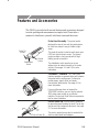 15
15
-
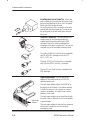 16
16
-
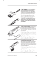 17
17
-
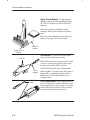 18
18
-
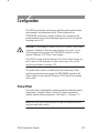 19
19
-
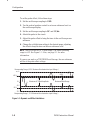 20
20
-
 21
21
-
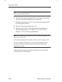 22
22
-
 23
23
-
 24
24
-
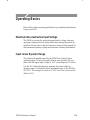 25
25
-
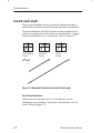 26
26
-
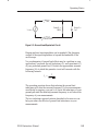 27
27
-
 28
28
-
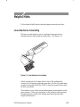 29
29
-
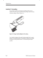 30
30
-
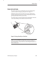 31
31
-
 32
32
-
 33
33
-
 34
34
-
 35
35
-
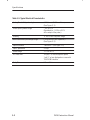 36
36
-
 37
37
-
 38
38
-
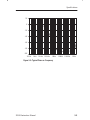 39
39
-
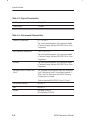 40
40
-
 41
41
-
 42
42
-
 43
43
-
 44
44
-
 45
45
-
 46
46
-
 47
47
-
 48
48
-
 49
49
-
 50
50
-
 51
51
-
 52
52
-
 53
53
-
 54
54
-
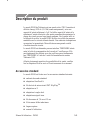 55
55
-
 56
56
-
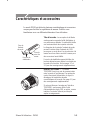 57
57
-
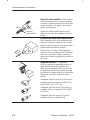 58
58
-
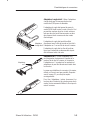 59
59
-
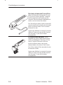 60
60
-
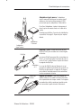 61
61
-
 62
62
-
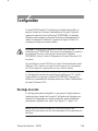 63
63
-
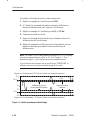 64
64
-
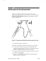 65
65
-
 66
66
-
 67
67
-
 68
68
-
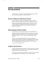 69
69
-
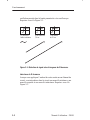 70
70
-
 71
71
-
 72
72
-
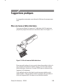 73
73
-
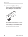 74
74
-
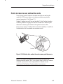 75
75
-
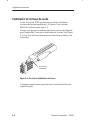 76
76
-
 77
77
-
 78
78
-
 79
79
-
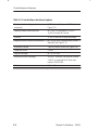 80
80
-
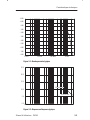 81
81
-
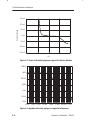 82
82
-
 83
83
-
 84
84
-
 85
85
-
 86
86
-
 87
87
-
 88
88
-
 89
89
-
 90
90
-
 91
91
-
 92
92
-
 93
93
-
 94
94
-
 95
95
-
 96
96
-
 97
97
-
 98
98
-
 99
99
-
 100
100
-
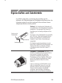 101
101
-
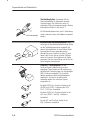 102
102
-
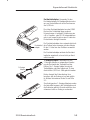 103
103
-
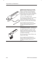 104
104
-
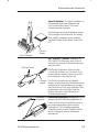 105
105
-
 106
106
-
 107
107
-
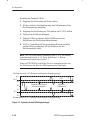 108
108
-
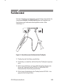 109
109
-
 110
110
-
 111
111
-
 112
112
-
 113
113
-
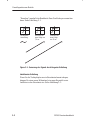 114
114
-
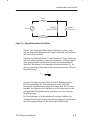 115
115
-
 116
116
-
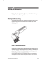 117
117
-
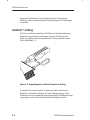 118
118
-
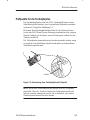 119
119
-
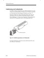 120
120
-
 121
121
-
 122
122
-
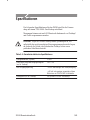 123
123
-
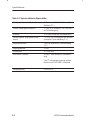 124
124
-
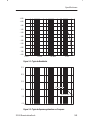 125
125
-
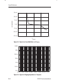 126
126
-
 127
127
-
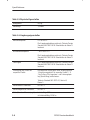 128
128
-
 129
129
-
 130
130
-
 131
131
-
 132
132
-
 133
133
-
 134
134
-
 135
135
-
 136
136
-
 137
137
-
 138
138
-
 139
139
-
 140
140
-
 141
141
-
 142
142
-
 143
143
-
 144
144
-
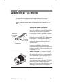 145
145
-
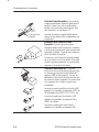 146
146
-
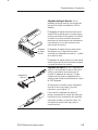 147
147
-
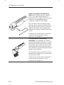 148
148
-
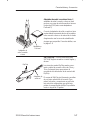 149
149
-
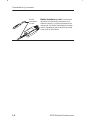 150
150
-
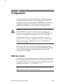 151
151
-
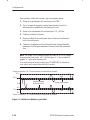 152
152
-
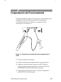 153
153
-
 154
154
-
 155
155
-
 156
156
-
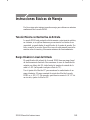 157
157
-
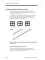 158
158
-
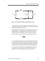 159
159
-
 160
160
-
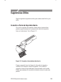 161
161
-
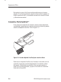 162
162
-
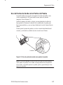 163
163
-
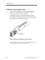 164
164
-
 165
165
-
 166
166
-
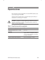 167
167
-
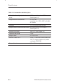 168
168
-
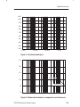 169
169
-
 170
170
-
 171
171
-
 172
172
-
 173
173
-
 174
174
-
 175
175
-
 176
176
-
 177
177
-
 178
178
-
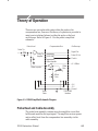 179
179
-
 180
180
-
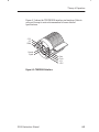 181
181
-
 182
182
-
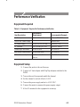 183
183
-
 184
184
-
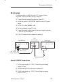 185
185
-
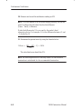 186
186
-
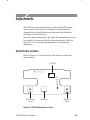 187
187
-
 188
188
-
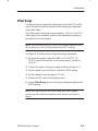 189
189
-
 190
190
-
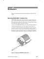 191
191
-
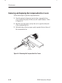 192
192
-
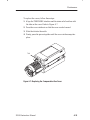 193
193
-
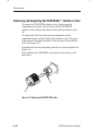 194
194
-
 195
195
-
 196
196
-
 197
197
-
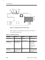 198
198
-
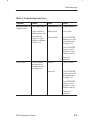 199
199
-
 200
200
-
 201
201
-
 202
202
-
 203
203
-
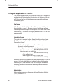 204
204
-
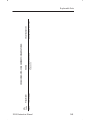 205
205
-
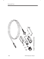 206
206
-
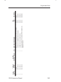 207
207
-
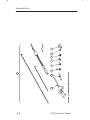 208
208
-
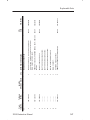 209
209
-
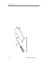 210
210
-
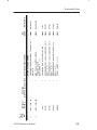 211
211
-
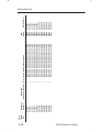 212
212


Tektronix P6245 El manual del propietario
- Tipo
- El manual del propietario
en otros idiomas
- français: Tektronix P6245 Le manuel du propriétaire
- English: Tektronix P6245 Owner's manual
- Deutsch: Tektronix P6245 Bedienungsanleitung