SICK WTx23-2 Compact photoelectric sensor Instrucciones de operación
- Tipo
- Instrucciones de operación

O P E R A T I N G I N S T R U C T I O N
WTx23-2
Compact photoelectric sensor
en / de / fr / it / pt / es / zh / ja / ru
8015974.YVM5
SICK AG, Erwin-Sick-Strasse 1, D-79183 Waldkirch

Photoelectric proximity sensor
Operating instructions
1 Safety notes
■
Read the operating instructions before commissioning.
■
Connection, mounting, and setting may only be performed by trained specialists.
■
Not a safety component in accordance with the EU Machinery Directive.
■
UL: Only for use in applications in accordance with NFPA 79. These devices shall
be protected by a 1 A fuse suitable for 30 V DC. Adapters listed by UL with connec‐
tion cables are available. Enclosure type 1.
■
When commissioning, protect the device from moisture and contamination.
■
These operating instructions contain information required during the life cycle of
the sensor.
2 Correct use
The WTx23-2 is an opto-electronic photoelectric proximity sensor (referred to as "sen‐
sor" in the following) for the optical, non-contact detection of objects, animals, and per‐
sons. If the product is used for any other purpose or modified in any way, any warranty
claim against SICK AG shall become void.
3 Commissioning
1 WT23-2, WTB23-2: Photoelectric proximity sensor with background suppression:
Check the application conditions: Adjust the sensing range and distance to the
object or background and the remission capability of the object according to the
corresponding diagram [H] (x = sensing range, y = transition range between the set
sensing range and suppression of the background as a % of the sensing range
(object remission/background remission)). Remission: 6% = black , 18% = gray
, 90% = white (referring to standard white as per DIN 5033).
The minimum distance (= y) for background suppression can be determined from
diagram [H] as follows:
Example: x = 400 mm, y = 30% => 30% % of 400 mm = 120 mm. That is, the
background is suppressed at a distance of > 520mm from the sensor.
WTE23-2: Photoelectric proximity sensor, energetic: Check the application condi‐
tions: Adjust the sensing range and the remission capability of the object according
to the corresponding diagram [H] (x = sensing range, y = operating reserve).
8015974.YVM5 | SICK
Subject to change without notice
1

During this process, an object can only be detected in front of a background if the
remission capability of the object is significantl
y higher than that of the background
or if the distance between the object and the background is sufficiently long.
% of sensing range
Image 1: H
2 Mount the sensor using a suitable mounting bracket (see the SICK range of acces‐
sories).
Not
e the sensor's maximum permissible tightening torque of 1.3 Nm.
Note the preferred direction of the object relative to the sensor [see A].
3 The sensors must be connected in a voltage-free state (U
v
= 0 V). The inf
ormation
in the g
raphics [B] must be observed, depending on the connection type:
– Male connector connection: pin assignment
– Cable: core color
Only apply voltage/switch on the power supply (U
v
> 0 V) once all electrical connec‐
tions have been es
tablished. The green LED indicator lights up on the sensor.
Explanations of the connection diagram (Graphic B):
Switching outputs Q and /Q (according to Graphic B):
WTx23-2P/K (PNP: load -> M)
WTx23-2N (NPN: load -> L+)
WTx23-2S (relay output)
Q: light switching, object will not be detected, relay active
4 WT23-2xxx4x, WTB23-2xxx6x: Align the sensor with the object. Select the position
so t
hat the red emitt
ed light beam hits the center of the object. You must ensure
that the optical opening (front screen) of the sensor is completely clear [E]. We rec‐
ommend making the adjustments using an object with a low remission.
3 COMMISSIONING
2
8015974.YVM5 | SICK
Subject to change wit
hout notice

WT(B)23-2xxx2x: Align the sensor with the object. Select the position so that the
infrared light (not visible) hits the center of the object. The correct alignment can
only be detected via the LED indicators. Please refer to Graphics C and E. You must
ensure that the optical opening (front screen) of the sensor is completely clear. We
recommend making the adjustments using an object with a low remission.
Image 2: E
5 Sensor which it is not possible to set (WT(B)23-2Xxxx0): The sensor is adjusted and
ready for operation.
Refer to Graphics C and G to check the function. If the switching output fails to
behave in accordance with Graphic C, check application conditions. See section
Fault diagnosis.
Sensor with potentiometer (WT(B)23-2Xxxx1):
The sensing range is adjusted with the potentiometer (type: 270°). Clockwise rota‐
tion: sensing range increased; counterclockwise rotation: sensing range reduced.
We recommend placing the switching state in the object, e.g., see Graphic F. Once
the sensing range has been adjusted, the object is removed from the path of the
beam, which causes the background to be suppressed and the switching output to
change (see Graphic C).
The sensor is adjusted and ready for operation. Refer to Graphics C and G to check
the function. If the switching output fails to behave in accordance with Graphic C,
check application conditions. See section Fault diagnosis.
Sensor with teach-in button (WTE23-2Xxxx2):
The sensing range is adjusted by pressing the teach-in button. Do not operate the
teach-in button using sharp objects. We recommend placing the switching state in
the object, e.g., see Graphic F. Once the sensing range has been adjusted, the
object is removed from the path of the beam, which causes the background to be
suppressed and the switching output to change (see Graphic C).
COMMISSIONING
3
8015974.YVM5 | SICK
Subject to change without notice
3

The sensitivity (sensing range) is adjusted by pressing the teach-in button. Do not
operate the teach-in button using sharp objects. Once the sensitivity is set, remove
the object from the beam path. The switching output changes (see Graphic C).
The sensor is adjusted and ready for operation. Refer to Graphics C and G to check
the function. If the switching output fails to behave in accordance with Graphic C,
check application conditions. See section Fault diagnosis.
Image 3: C
Image 4: G
Teach-in mode
for objects /
Teach-in mode
for objects
Teach-in time /
Teach-in time
Alignment /
Alignment
LED indicator /
LED indicator
Results /
Results
Single teach-in
pushbutton /
Single teach-in
pushbutton
> 2 ... < 4 s Sensor to
object /
Sensor to object
Sensing range is
adjusted accord‐
ing to object /
Sensing range is
adjusted accord‐
ing to object
5 Fault diagnosis
Table indicates which measures are to be taken if the sensor stops working.
4
4
8015974.YVM5 | SICK
Subject to change without notice

6 Devices with special features
WT23-2P1121S01: Sensing range can be set between approx. 30 and 400 mm. The
detection of objects is heavily restricted in the 0 to 30 mm range, with special male
connector, 6-pin, JST, 06HR-4K: pin 1: L+, pin 2: not connected, pin 3: 0 V, pin 4: Q
WT23-2P2421S03: Sensing range max.: 50 to 1,300 mm on white (90% remission),
ambient operating temperature -30 to +60 °C
WTB23-2P2401S04: Sensing range max.: 30 to 1,600 mm on white (90% remission),
infrared light
WT23-201521S05: Sensing range max.: 30 to 1,300 mm on white (90% remission),
supply voltage: 10 to 30 V DC, power consumption: ≤ 50 mA, switching current (switch‐
ing voltage): 100 mA (20 V AC), 100 mA (30 V DC), switching output: semiconductor
relay, galvanically isolated, response time: ≤ 3 ms, switching frequency: 200 Hz
WT23-2P2421S06: Sensing range max.: 200 to 1,000 mm on white (90% remission),
response time: ≤ 6.25 ms, switching frequency: 80 Hz
WTB23-2P1121S07: Sensing range max.: 30…2,300 mm on white (90% remission)
WTB23-2P2461S08: Sensing range max.: 30 to 1,100 mm on white (90% remission),
response time: ≤ 6.25 ms, switching frequency: 80 Hz
7 Table : Fault diagnosis
LED indicator/fault pattern /
LED indicator/fault pattern
Cause /
Cause
Measures /
Measures
Green LED does not light up /
Green LED does not light up
No voltage or voltage below
the limit values /
No voltage or voltage below
the limit values
Check the power supply,
check all electrical connec‐
tions (cables and plug connec‐
tions) /
Check the power supply,
check all electrical connec‐
tions (cables and plug connec‐
tions)
Green LED does not light up /
Green LED does not light up
Voltage interruptions /
Voltage interruptions
Ensure there is a stable power
supply without interruptions /
Ensure there is a stable power
supply without interruptions
Green LED does not light up /
Green LED does not light up
Sensor is faulty /
Sensor is faulty
If the power supply is OK,
replace the sensor /
If the power supply is OK,
replace the sensor
WT(B)23-2: Yellow LED
flashes /
WT(B)23-2: Yellow LED flashes
Sensor is still ready for opera‐
tion, but the operating condi‐
tions are not ideal /
Sensor is still ready for opera‐
tion, but the operating condi‐
tions are not ideal
Check the operating condi‐
tions: Fully align the beam of
light (light spot) with the
object. / Clean the optical sur‐
faces . / Readjust the sensitiv‐
ity (potentiometer) (teach-in) /
Check sensing range and
adjust if necessary; see
graphic F. / H. /
Check the operating condi‐
tions: Fully align the beam of
light (light spot) with the
object. / Clean the optical sur‐
faces . / Readjust the sensitiv‐
DEVICES WITH SPECIAL FEATURES 6
8015974.YVM5 | SICK
Subject to change without notice
5

LED indicator/fault pattern /
LED indicator/fault pattern
Cause /
Cause
Measures /
Measures
ity (potentiometer) (teach-in) /
Check sensing range and
adjust if necessary; see
graphic F. / H.
WTE23-2: Yellow LED flashes
(only briefly) /
WTE23-2: Yellow LED flashes
(only briefly)
Teach-in mode /
Teach-in mode
Check the teach-in mode /
Check the teach-in mode
WT(B)23-2: Yellow LED lights
up, no object in the path of the
beam /
WT(B)23-2: Yellow LED lights
up, no object in the path of the
beam
/ Distance between the sen‐
sor and the background is too
short /
/ Distance between the sen‐
sor and the background is too
short
Reduce the sensing range,
see graphic F / H /
Reduce the sensing range,
see graphic F / H
WTE23-2: Yellow LED lights up,
no object in the path of the
beam /
WTE23-2: Yellow LED lights up,
no object in the path of the
beam
Remission capability of the
background is excessive /
Remission capability of the
background is excessive
Check changes to the back‐
ground. Reduce the sensitivity
of the sensor or use sensors
with background suppres‐
sion /
Check changes to the back‐
ground. Reduce the sensitivity
of the sensor or use sensors
with background suppression
WT(B)23-2: Object is in the
path of the beam, yellow LED
does not light up /
WT(B)23-2: Object is in the
path of the beam, yellow LED
does not light up
Distance between the sensor
and the object is too long or
sensing range is set too
short /
Distance between the sensor
and the object is too long or
sensing range is set too short
Increase the sensing range,
see graphic F / H /
Increase the sensing range,
see graphic F / H
WTE23-2: Object is in the path
of the beam, yellow LED does
not light up /
WTE23-2: Object is in the path
of the beam, yellow LED does
not light up
Sensitivity is set too low or dis‐
tance between the sensor and
the object is too long /
Sensitivity is set too low or dis‐
tance between the sensor and
the object is too long
Increase the sensing range,
take note of the distance
between the sensor and the
background, see graphic F /
H /
Increase the sensing range,
take note of the distance
between the sensor and the
background, see graphic F / H
WTE23-2: Object is in the path
of the beam, yellow LED does
not light up /
WTE23-2: Object is in the path
of the beam, yellow LED does
not light up
Remission capability of the
object is insufficient /
Remission capability of the
object is insufficient
Increase the sensing range,
take note of the distance
between the sensor and the
background, see graphic F /
H /
Increase the sensing range,
take note of the distance
between the sensor and the
background, see graphic F / H
8 Disassembly and disposal
The sensor must be disposed of according to the applicable country-specific regula‐
tions. Efforts should be made during the disposal process to recycle the constituent
materials (particularly precious metals).
8 DISASSEMBLY AND DISPOSAL
6
8015974.YVM5 | SICK
Subject to change without notice

9 Maintenance
SICK sensors are maintenance-free.
We recommend doing the following regularly:
•
Clean the external lens surfaces
•
Check the screw connections and plug-in connections
No modifications may be made to devices.
Subject to change without notice. Specified product properties and technical data are
not written guarantees.
10 Technical
data
WT23-2Xxx4x WT23-2P/Nxx2x WT23-2Sxx2x WTE23-2
Sensing range 100 ... 800 mm 100 ... 1000 mm 100 ... 1000 mm 300 ... 2000 mm
Sensing range max. 50 ... 800 mm
1)
50 ... 1000 mm
1)
50 ... 1000 mm
1)
50 ... 2300 mm
1)
Light spot diameter/distance 30 mm / 800
mm
50 mm / 800
mm
50 mm / 800
mm
160 mm / 2000
mm
Supply voltage V
S
DC 10 ... 30 V
2)
DC 10 ... 30 V
2)
AC 90 ... 250 V
3)
DC 10 ... 30 V
2)
Output current I
max.
≤ 100 mA ≤ 100 mA ≤ 100 mA
Switching current (switching voltage) 3 A @ AC 250 V /
or DC 24 V
4)
Max. switching frequency 200 Hz
5)
200 Hz
5)
10 Hz
5)
200 Hz
5)
Max. response time ≤ 2.5 ms
6)
≤ 2.5 ms
6)
≤ 10 ms
6)
≤ 2.5 ms
6)
Enclosure rating IP 65 IP 65 IP 65 IP 65
Protection class II
7)
II
7)
II
8)
II
7)
Circuit protection A,B,C,D
9)
A,B,C,D
9)
A,C
9)
A,B,C,D
9)
Ambient operating temperature -25 ... +60 °C -25 ... +60 °C -25 ... +60 °C -25 ... +60 °C
1)
Object with 90 % remission (based on standard
white DIN 5033)
2)
Limit value: operation in short-circuit protection
mains max. 8 A; residual ripple max. 5 Vss
3)
Limit values
4)
Usage category to EN 60947-1 AC-15, DC-13
5)
With light / dark ratio 1:1
6)
Signal transit time with resistive load
7)
Reference voltage DC 50 V
8)
Rated voltage AC 250 V, overvoltage category 2
9)
A = UV-connections reverse polarity protected
C = Interference suppression
MAINTENANCE 9
8015974.YVM5 | SICK
Subject to change wit
hout notice
7
WTB23-2Xxx6x
300 ... 1100 mm
1)
100 ... 1100 mm
1)
12 mm / 800
mm
DC 10 ... 30 V
2)
≤ 100 mA
200 Hz
5)
≤ 2.5 ms
6)
IP 67
II
7)
A,B,C,D
9)
-30 ... +60 °C
B = inputs and outputs reverse-polarity protected
D = outputs overcurrent and short-circuit
protected

Reflexions-Lichttaster
Betriebsanleitung
11 Sicherheitshinweise
■
Vor der Inbetriebnahme die Betriebsanleitung lesen.
■
Anschluss, Montage und Einstellung nur durch Fachpersonal.
■
Kein Sicherheitsbauteil gemäß EU-Maschinenrichtlinie.
■
UL: Nur zur Verwendung in Anwendungen gemäß NFPA 79. Diese Geräte müssen
mit einer für 30V DC geeigneten 1A-Sicherung abgesichert werden. Von UL gelis‐
tete Adapter mit Anschlusskabeln sind verfügbar. Enclosure type 1.
■
Gerät bei Inbetriebnahme vor Feuchte und Verunreinigung schützen.
■
Diese Betriebsanleitung enthält Informationen, die während des Lebenszyklus des
Sensors notwendig sind.
12 Bestimmungsgemäße Verwendung
Die WTx23-2 ist ein optoelektronischer Reflexions-Lichttaster (im Folgenden Sensor
genannt) und wird zum optischen, berührungslosen Erfassen von Sachen, Tieren und
Personen eingesetzt. Bei jeder anderen Verwendung und bei Veränderungen am Pro‐
dukt verfällt jeglicher Gewährleistungsanspruch gegenüber der SICK AG.
13 Inbetriebnahme
1 WT23-2, WTB23-2: Reflexions-Lichttaster mit Hintergrundausblendung: Einsatzbe‐
dingungen prüfen: Schaltabstand und Distanz zum Objekt bzw. Hintergrund sowie
Remissionsvermögen des Objektes mit dem zugehörigen Diagramm [vgl. H] abglei‐
chen (x = Schaltabstand, y = Übergangsbereich zwischen eingestelltem Schaltab‐
stand und Ausblendung des Hintergrundes in % des Schaltabstands (Remission
Objekt / Remission Hintergrund)). Remission: 6 % = schwarz , 18 % = grau ,
90 % = weiß (bezogen auf Standardweiß nach DIN 5033).
Die minimale Distanz (= y) für die Hintergrundausblendung kann aus dem Dia‐
gramm [vgl. H] wie folgt ermittelt werden:
Beispiel: x = 400 mm, y = 30% => 30% % von 400 mm = 120 mm. D. h. der Hinter‐
grund wird ab einer Distanz von > 520 mm vom Sensor ausgeblendet.
WTE23-2: Reflexions-Lichttaster, energetisch: Einsatzbedingungen prüfen: Schalt‐
abstand und Remissionsvermögen des Objektes mit dem zugehörigen Diagramm
[vgl. H] abgleichen. (x = Schaltabstand, y = Funktionsreserve).
8
8015974.YVM5 | SICK
Subject to change without notice

Dabei kann ein Objekt vor einem Hintergrund nur detektiert werden, wenn das
Remissionsv
ermögen des Objektes deutlich größer ist als das Remissionsvermö‐
gen des Hintergrundes oder der Abstand zwischen Objekt und Hintergrund ausrei‐
chend groß ist.
% of sensing range
Abb. 5: H
2 Den Sensor an einen geeigneten Befestigungswinkel montieren (siehe SICK-Zube‐
hör-Pr
ogramm).
Maximal zulässiges Anzugsdrehmoment des Sensors von 1.3 Nm beachten.
Vorzugsrichtung des Objektes zum Sensor beachten [vgl. A].
3 Anschluss der Sensoren muss spannungsfrei (U
V
= 0 V) er
f
olgen. Je nach
Anschlussart sind die Informationen in den Grafiken [vgl. B] zu beachten:
– Steckeranschluss: Pinbelegung
– Leitung: Adernfarbe
Erst nach Anschluss aller elektrischen Verbindungen die Spannungsversorgung (U
V
> 0 V) anlegen bzw
. einschalten. Am Sensor leuchtet die grüne Anzeige-LED.
Erläuterungen zum Anschlussschema (Grafik B):
Schaltausgänge Q bzw. /Q (gemäß Grafik B):
WTx23-2P / K (PNP: Last -> M)
WTx23-2N (NPN: Last -> L+)
WTx23-2S (Ausgang Relais)
Q: hellschaltend, Objekt wird nicht erkannt, Relais aktiv
4 WT23-2xxx4x, WTB23-2xxx6x: Sensor auf Objekt ausrichten. Positionierung so
w
ählen, dass der r
ote Sendelichtstrahl in der Mitte des Objekts auftrifft. Es ist
darauf zu achten, dass die optische Öffnung (Frontscheibe) des Sensors vollstän‐
dig frei ist [vgl. E]. Wir empfehlen, die Einstellung mit einem Objekt von niedriger
Remission vorzunehmen.
INBETRIEBNAHME 13
8015974.YVM5 | SICK
Subject to c
hange without notice
9

WT(B)23-2xxx2x: Sensor auf Objekt ausrichten. Positionierung so wählen, dass das
Infrarotlicht (nicht sichtbar) in der Mitte des Objekts auftrifft. Die korrekte Ausrich‐
tung kann nur über die Anzeige-LEDs erkannt werden. Siehe dazu Grafiken C und
E. Es ist darauf zu achten, dass die optische Öffnung (Frontscheibe) des Sensors
vollständig frei ist. Wir empfehlen, die Einstellung mit einem Objekt von niedriger
Remission vorzunehmen.
Abb. 6: E
5 Sensor ohne Einstellmöglichkeit (WT(B)23-2Xxxx0): Sensor ist eingestellt und
betriebsbereit.
Zur Überprüfung der Funktion Grafik C und G heranziehen. Verhält sich der Schalt‐
ausgang nicht gemäß Grafik C, Einsatzbedingungen prüfen. Siehe Abschnitt Fehler‐
diagnose.
Sensor mit Potentiometer (WT(B)23-2Xxxx1):
Mit dem Potentiometer (Art: 270°) wird der Schaltabstand eingestellt. Drehung
nach rechts: Erhöhung des Schaltabstandes, Drehung nach links: Verringerung des
Schaltabstandes. Wir empfehlen, den Schaltabstand in das Objekt zu legen, z. B.
siehe Grafik F. Nachdem der Schaltabstand eingestellt worden ist, das Objekt aus
dem Strahlengang entfernen, der Hintergrund wird dabei ausgeblendet und der
Schaltausgang ändert sich (siehe Grafik C).
Sensor ist eingestellt und betriebsbereit. Zur Überprüfung der Funktion Grafik C
und G heranziehen. Verhält sich der Schaltausgang nicht gemäß Grafik C, Einsatz‐
bedingungen prüfen. Siehe Abschnitt Fehlerdiagnose.
Sensor mit Teach-in-Taste (WTE23-2Xxxx2):
Durch Drücken der Teach-in-Taste wird der Schaltabstand eingestellt. Teach-in-
Taste nicht mit spitzen Gegenständen betätigen. Wir empfehlen, den Schaltab‐
stand in das Objekt zu legen, z. B. siehe Grafik F. Nach dem der Schaltabstand ein‐
gestellt worden ist, das Objekt aus dem Strahlengang entfernen, der Hintergrund
wird dabei ausgeblendet und der Schaltausgang ändert sich (siehe Grafik C).
13
INBETRIEBNAHME
10
8015974.YVM5 | SICK
Subject to change without notice

Durch Drücken der Teach-in-Taste wird die Empfindlichkeit (Schaltabstand) einge‐
stellt. Teach-in-Taste nicht mit spitzen Gegenständen betätigen. Nachdem die Emp‐
findlichkeit eingestellt worden ist, das Objekt aus dem Strahlengang entfernen. Der
Schaltausgang ändert sich (siehe Grafik C).
Sensor ist eingestellt und betriebsbereit. Zur Überprüfung der Funktion Grafik C
und G heranziehen. Verhält sich der Schaltausgang nicht gemäß Grafik C, Einsatz‐
bedingungen prüfen. Siehe Abschnitt Fehlerdiagnose.
Abb. 7: C
Abb. 8: G
Teach-in-Modus
für Objekte /
Teach-in mode
for objects
Teach-in-Zeit /
Teach-in time
Ausrichtung /
Alignment
Anzeige-LED /
LED indicator
Ergebnis /
Results
Einfach-Teach-in-
Taste /
Single teach-in
pushbutton
> 2 ... < 4 s Sensor auf
Objekt /
Sensor to object
Schaltabstand
wird auf Objekt
eingestellt /
Sensing range is
adjusted accor‐
ding to object
14
8015974.YVM5 | SICK
Subject to change without notice
11

15 Fehlerdiagnose
Tabelle I zeigt, welche Maßnahmen durchzuführen sind, wenn die Funktion des Sensors
nicht mehr gegeben ist.
16 Geräte mit besonderen Merkmalen
WT23-2P1121S01: Schaltabstand ist einstellbar zwischen ca. 30 ... 400 mm. Die
Detektion von Objekten ist im Bereich 0 ... 30 mm stark eingeschränkt worden, mit
Sonderstecker, 6-polig, JST, 06HR-4K: Pin1: L+, Pin2: not connected, Pin3: 0 V, Pin 4: Q
WT23-2P2421S03: Schaltabstand max.: 50 ... 1.300 mm auf weiß (90 % Remission),
Betriebsumgebungstemperatur -30 ... +60 °C
WTB23-2P2401S04: Schaltabstand max.: 30 ... 1.600 mm auf weiß (90 % Remission),
Infrarotlicht
WT23-201521S05: Schaltabstand max.: 30 ... 1.300 mm auf weiß (90 % Remission),
Versorgungsspannung: 10 ... 30 V DC, Leistungsaufnahme: ≤ 50 mA, Schaltstrom
(Schaltspannung): 100 mA (20 V AC), 100 mA (30 V DC), Schaltausgang: Halbleiterre‐
lais, galvanisch getrennt, Ansprechzeit: ≤ 3 ms, Schaltfrequenz: 200 Hz
WT23-2P2421S06: Schaltabstand max.: 200 ... 1.000 mm auf weiß (90 % Remission),
Ansprechzeit: ≤ 6,25 ms, Schaltfrequenz: 80 Hz
WTB23-2P1121S07: Schaltabstand mx.: 30 ... 2.300 mm auf weiß (90 % Remission)
WTB23-2P2461S08: Schaltabstand max.: 30 ... 1.100 mm auf weiß (90 % Remission),
Ansprechzeit: ≤ 6,25 ms, Schaltfrequenz: 80 Hz
17 Tabelle Fehlerdiagnose
Anzeige-LED / Fehlerbild /
LED indicator/fault pattern
Ursache /
Cause
Maßnahme /
Measures
grüne LED leuchtet nicht /
Green LED does not light up
keine Spannung oder Span‐
nung unterhalb der Grenz‐
werte /
No voltage or voltage below
the limit values
Spannungsversorgung prüfen,
den gesamten elektrischen
Anschluss prüfen (Leitungen
und Steckerverbindungen) /
Check the power supply,
check all electrical connecti‐
ons (cables and plug connecti‐
ons)
grüne LED leuchtet nicht /
Green LED does not light up
Spannungsunterbrechungen /
Voltage interruptions
Sicherstellen einer stabilen
Spannungsversorgung ohne
Unterbrechungen /
Ensure there is a stable power
supply without interruptions
grüne LED leuchtet nicht /
Green LED does not light up
Sensor ist defekt /
Sensor is faulty
Wenn Spannungsversorgung
in Ordnung ist, dann Sensor
austauschen /
If the power supply is OK,
replace the sensor
WT(B)23-2: gelbe LED blinkt /
WT(B)23-2: Yellow LED flashes
Sensor ist noch betriebsbe‐
reit, aber die Betriebsbedin‐
gungen sind nicht optimal /
Sensor is still ready for opera‐
tion, but the operating conditi‐
ons are not ideal
Betriebsbedingungen prüfen:
Lichtstrahl (Lichtfleck) voll‐
ständig auf das Objekt aus‐
richten / Reinigung der opti‐
schen Flächen / Empfindlich‐
keit (Potentiometer) (Teach)
15 FEHLERDIAGNOSE
12
8015974.YVM5 | SICK
Subject to change without notice

Anzeige-LED / Fehlerbild /
LED indicator/fault pattern
Ursache /
Cause
Maßnahme /
Measures
neu einstellen / Schaltab‐
stand überprüfen und ggf.
anpassen, siehe Grafik F. /
H. /
Check the operating conditi‐
ons: Fully align the beam of
light (light spot) with the
object. / Clean the optical sur‐
faces . / Readjust the sensiti‐
vity (potentiometer) (teach-
in) / Check sensing range and
adjust if necessary; see gra‐
phic F. / H.
WTE23-2: gelbe LED blinkt (nur
kurz) /
WTE23-2: Yellow LED flashes
(only briefly)
Teach-Modus /
Teach-in mode
Teach-Modus überprüfen /
Check the teach-in mode
WT(B)23-2: gelbe LED leuchtet,
kein Objekt im Strahlengang /
WT(B)23-2: Yellow LED lights
up, no object in the path of the
beam
Abstand zwischen Sensor und
Hintergrund ist zu gering /
/ Distance between the sen‐
sor and the background is too
short
Schaltabstand verringern,
siehe Grafik F / H /
Reduce the sensing range,
see graphic F / H
WTE23-2: gelbe LED leuchtet,
kein Objekt im Strahlengang /
WTE23-2: Yellow LED lights up,
no object in the path of the
beam
Remissionsvermögen des Hin‐
tergrundes zu hoch /
Remission capability of the
background is excessive
Veränderungen des Hinter‐
grundes prüfen. Empfindlich‐
keit des Sensors reduzieren
oder Taster mit Hintergrun‐
dausblendung verwenden /
Check changes to the back‐
ground. Reduce the sensitivity
of the sensor or use sensors
with background suppression
WT(B)23-2: Objekt ist im Strah‐
lengang, gelbe LED leuchtet
nicht /
WT(B)23-2: Object is in the
path of the beam, yellow LED
does not light up
Abstand zwischen Sensor und
Objekt ist zu groß oder Schalt‐
abstand ist zu gering einge‐
stellt /
Distance between the sensor
and the object is too long or
sensing range is set too short
Schaltabstand vergrößern,
siehe Grafik F / H /
Increase the sensing range,
see graphic F / H
WTE23-2: Objekt ist im Strah‐
lengang, gelbe LED leuchtet
nicht /
WTE23-2: Object is in the path
of the beam, yellow LED does
not light up
Empfindlichkeit ist zu gering
eingestellt oder Abstand zwi‐
schen Sensor und Objekt ist
zu groß /
Sensitivity is set too low or dis‐
tance between the sensor and
the object is too long
Schaltabstand vergrößern,
Abstand zwischen Sensor und
Hintergrund beachten, siehe
Grafik F / H /
Increase the sensing range,
take note of the distance bet‐
ween the sensor and the
background, see graphic F / H
WTE23-2: Objekt ist im Strah‐
lengang, gelbe LED leuchtet
nicht /
WTE23-2: Object is in the path
of the beam, yellow LED does
not light up
Remissionsvermögen des
Objektes ist zu gering /
Remission capability of the
object is insufficient
Schaltabstand vergrößern,
Abstand zwischen Sensor und
Hintergrund beachten, siehe
Grafik F / H /
Increase the sensing range,
take note of the distance bet‐
ween the sensor and the
background, see graphic F / H
TABELLE FEHLERDIAGNOSE 17
8015974.YVM5 | SICK
Subject to change without notice
13

18 Demontage und Entsorgung
Die Entsorgung des Sensors hat gemäß den länderspezifisch anwendbaren Vorschrif‐
ten zu er
folgen. Für die enthaltenen Wertstoffe (insbesondere Edelmetalle) ist im Rah‐
men der Entsorgung eine Verwertung anzustreben.
19 Wartung
SICK-Sensoren sind wartungsfrei.
Wir em
pfehlen, in regelmäßigen Abständen
•
die optischen Grenzflächen zu reinigen
•
Verschraubungen und Steckverbindungen zu überprüfen
Veränderungen an Geräten dürfen nicht vorgenommen werden.
Irrtümer und Änderungen vorbehalten. Angegebene Produkteigenschaften und techni‐
sche Daten stellen keine Garantieerklärung dar.
20 Technische Daten
WT23-2Xxx4x WT23-2P/Nxx2x WT23-2Sxx2x WTE23-2
Schaltabstand 100 ... 800 mm 100 ... 1000 mm 100 ... 1000 mm 300 ... 2000 mm
Schaltabstand max. 50 ... 800 mm
1)
50 ... 1000
mm
1)
50 ... 1000
mm
1)
50 ... 2300
mm
1)
Lichtfleckdurchmesser/Entfernung 30 mm / 800
mm
50 mm / 800
mm
50 mm / 800
mm
160 mm / 2000
mm
Versorgungsspannung U
V
DC 10 ... 30 V
2)
DC 10 ... 30 V
2)
AC 90 ... 250 V
3)
DC 10 ... 30 V
2)
Ausgangsstrom I
max.
≤ 100 mA ≤ 100 mA ≤ 100 mA
Schaltstrom (Schaltspannung) 3 A @ AC 250
V /or DC 24 V
4)
Schaltfolge max. 200 Hz
5)
200 Hz
5)
10 Hz
5)
200 Hz
5)
Ansprechzeit max. ≤ 2.5 ms
6)
≤ 2.5 ms
6)
≤ 10 ms
6)
≤ 2.5 ms
6)
Schutzart IP 65 IP 65 IP 65 IP 65
Schutzklasse II
7)
II
7)
II
8)
II
7)
Schutzschaltungen A,B,C,D
9)
A,B,C,D
9)
A,C
9)
A,B,C,D
9)
Betriebsumgebungstemperatur -25 ... +60 °C -25 ... +60 °C -25 ... +60 °C -25 ... +60 °C
1)
Tastgut mit 90 % Remission (bezogen auf Stan‐
dard-Weiß DIN 5033)
2)
Grenzwerte: Betrieb im kurzschlussgeschütz‐
ten Netz max. 8 A; Restwelligkeit max. 5 Vss
3)
Grenzwerte
4)
Gebrauchskategorie nach EN 60947-1 AC-15,
DC-13
5)
Mit Hell- / Dunkelverhältnis 1:1
6)
Signallaufzeit bei ohmscher Last
7)
Bemessungsspannung DC 50 V
8)
Bemessungsspannung AC 250 V, Überspan‐
nungskategorie 2
9)
A = U
V
-Anschlüsse verpolsicher
B = Ein- und Ausgänge verpolsicher
C = Störimpulsunterdrückung
D = Ausgänge überstrom- und kurzschlussfest
18 DEMONTAGE UND ENTSORGUNG
14
8015974.YVM5 | SICK
Subject to c
hange without notice
WTB23-2Xxx6x
30 ... 1100 mm
1)
100 ... 1100
mm
1)
12 mm / 800
mm
DC 10 ... 30 V
2)
≤ 100 mA
200 Hz
5)
≤ 2.5 ms
6)
IP 67
II
7)
A,B,C,D
9)
-30 ... +60 °C

TECHNISCHE DATEN 20
8015974.YVM5 | SICK
Subject t
o change without notice
15

Détecteur à réflexion directe
Notice d'instruction
21 Consignes de sécurité
■
Lire la notice d'instruction avant la mise en service.
■
Confier le raccordement, le montage et le réglage uniquement à un personnel spé‐
cialisé.
■
Il ne s'agit pas d'un composant de sécurité au sens de la directive machines CE.
■
UL : utilisation uniquement dans des applications selon la NFPA 79. Ces appareils
doivent être protégés par un fusible de 1 A adapté à du 30 V C.C. Des adaptateurs
listés UL avec câbles de connexion sont disponibles. Enclosure type 1.
■
Protéger l'appareil contre l'humidité et les impuretés lors de la mise en service.
■
Cette notice d'instruction contient des informations nécessaires pendant toute la
durée de vie du capteur.
22 Utilisation conforme
Le WTx23-2 est un détecteur à réflexion directe optoélectronique (appelé capteur dans
ce document) qui permet la détection optique sans contact d'objets, d'animaux et de
personnes. Toute autre utilisation ou modification du produit annule la garantie de
SICK AG.
23 Mise en service
1 WT23-2, WTB23-2 : détecteur à réflexion directe avec élimination d'arrière-plan :
vérifier les conditions d'utilisation : comparer la portée et la distance à l'objet ou à
l'arrière-plan et les caractéristiques de réflectivité avec le diagramme correspon‐
dant [cf. H] (x = portée, y = zone de transition entre la portée réglée et le mas‐
quage de l'arrière-plan en % de la portée (réflectivité de l'objet / réflectivité de l'ar‐
rière-plan)). Réflectivité : 6 % = noir , 18 % = gris , 90 % = blanc (par rapport
au blanc standard selon DIN 5033).
La distance minimale (=y) pour l'élimination d'arrière-plan peut être calculée à par‐
tir du diagramme [E] comme suit :
Exemple : x = 400 mm, y = 30% => 30% % de 400 mm = 120 mm. C'est à dire que
l'arrière-plan est masqué à partir d'une distance du capteur > 520 .
WTE23-2 : détecteur à réflexion directe, énergétique : vérifier les conditions d'utili‐
sation : comparer la portée et les caractéristiques de réflectivité de l'objet à l'aide
du diagramme [cf. H] correspondant. (x = portée, y = réserve de fonctionnement).
16
8015974.YVM5 | SICK
Subject to change without notice

Ce faisant, il n'est possible de détecter un objet devant un arrière-plan que si les
caract
éristiques de réflectivité de l'objet sont largement supérieures à celles de
l'arrière-plan en question ou si la distance entre l'objet et l'arrière-plan est suffi‐
sante.
% of sensing range
Image 9: H
2 Monter le capteur sur une équerre de fixation adaptée (voir la gamme d'accessoi‐
res SIC
K).
Respecter le couple de serrage maximum autorisé du capteur de 1.3 Nm
Tenir compte de la direction préférentielle de l'objet par rapport au capteur [voir A].
3 Le raccordement des capteurs doit s'effectuer hors tension (U
v
= 0 V). Selon le
mode de r
accor
dement, respecter les informations contenues dans les schémas
[B] :
– Raccordement du connecteur : affectation des broches
– Câble : couleur des fils
Après avoir terminé tous les raccordements électriques, enclencher l'alimentation
électriq
ue (U
v
> 0 V). La DEL verte s'allume sur le capteur.
Explications relatives au schéma de raccordement (schéma B) :
Sorties de commutation Q ou /Q (selon le schéma B) :
WTx23-2P/K (PNP : charge -> M)
WTx23-2N (NPN : charge -> L+)
WTx23-2S (sortie relais)
Q : commutation claire, l'objet n'est pas détecté, relais actif
4 WT23-2xxx4x, WTB23-2xxx6x : aligner le capteur sur l'objet. Sélectionner la posi‐
tion de sor
t
e que le faisceau lumineux émis rouge touche l'objet en plein milieu.
S'assurer que l'ouverture optique (vitre frontale) du capteur est parfaitement déga‐
gée [voir E]. Nous recommandons de procéder au réglage avec un objet peu réflé‐
chissant.
MISE EN SERVICE 23
8015974.YVM5 | SICK
Subject to c
hange without notice
17

WT(B)23-2xxx2x : aligner le capteur sur l'objet. Sélectionner la position de sorte
que le faisceau infrarouge (invisible) touche l'objet en plein milieu. Seules les LED
permettent de savoir si l'alignement est correct. Pour cela voir les schémas C et E.
S'assurer que l'ouverture optique (vitre frontale) du capteur est parfaitement déga‐
gée. Nous recommandons de procéder au réglage avec un objet peu réfléchissant.
Image 10: E
5 Capteur sans possibilité de réglage (WT(B)23-2Xxxx0) : le capteur est réglé et prêt
à l'emploi.
Pour contrôler le fonctionnement, utiliser les schémas C et G. Si la sortie de com‐
mutation ne se comporte pas comme indiqué sur le schéma C, vérifier les condi‐
tions d'utilisation. Voir la section consacrée au diagnostic.
Capteur avec potentiomètre (WT(B)23-2Xxxx1) :
La portée se règle avec le potentiomètre (réf. : 270°). Rotation vers la droite : aug‐
mentation de la portée, rotation vers la gauche : réduction de la portée. Nous
recommandons de régler la portée sur l'objet, par ex. voir schéma F. Après le
réglage de la portée, retirer l'objet de la trajectoire du faisceau, ce qui élimine l'ar‐
rière-plan et fait basculer la sortie de commutation (voir le schéma C).
Le capteur est réglé et prêt à être utilisé. Pour contrôler le fonctionnement, utiliser
les schémas C et G. Si la sortie de commutation ne se comporte pas comme indi‐
qué sur le schéma C, vérifier les conditions d'utilisation. Voir la section consacrée
au diagnostic.
Capteur avec touche apprentissage (WTE23-2Xxxx2) :
Appuyer sur la touche apprentissage pour régler la portée. Ne pas appuyer sur la
touche apprentissage avec des objets pointus. Nous recommandons de régler la
portée sur l'objet, par ex. voir schéma F. Après le réglage de la portée, retirer l'objet
de la trajectoire du faisceau, ce qui élimine l'arrière-plan et fait basculer la sortie
de commutation (voir le schéma C).
23
MISE EN SERVICE
18
8015974.YVM5 | SICK
Subject to change without notice

Appuyer sur la touche apprentissage pour régler la sensibilité (portée). Ne pas
appuyer sur la touche apprentissage avec des objets pointus. Après avoir réglé la
sensibilité, retirer l'objet du faisceau. La sortie de commutation bascule (voir
schéma C).
Le capteur est réglé et prêt à être utilisé. Pour contrôler le fonctionnement, utiliser
les schémas C et G. Si la sortie de commutation ne se comporte pas comme indi‐
qué sur le schéma C, vérifier les conditions d'utilisation. Voir la section consacrée
au diagnostic.
Image 11: C
Image 12: G
Mode d'appren‐
tissage pour les
objets /
Teach-in mode
for objects
Durée d'appren‐
tissage /
Teach-in time
Alignement /
Alignment
LED d'état /
LED indicator
Résultat /
Results
Touche d'appren‐
tissage simple /
Single teach-in
pushbutton
> 2 ... < 4 s Capteur sur l'ob‐
jet /
Sensor to object
La portée est
réglée sur l'ob‐
jet /
Sensing range is
adjusted accord‐
ing to object
24
8015974.YVM5 | SICK
Subject to change without notice
19

25 Diagnostic
Le tableau I présente les mesures à appliquer si le capteur ne fonctionne plus.
26 Appareils avec caractéristiques spécifiques
WT23-2P1121S01 : portée réglable entre 30 et 400 mm env. La détection d'objets a
été fortement limitée dans une plage comprise entre 0 et 30 mm, avec connecteur spé‐
cial, 6 pôles, JST, 06HR-4K : broche 1 : L+, broche 2 : non connectée, broche 3 : 0 V,
broche 4 : Q
WT23-2P2421S03 : portée max. : 50 à 1.300 mm sur du blanc (réflectivité de 90 %),
température de service -30 à +60 °C
WTB23-2P2401S04 : portée max. : 30 à 1.600 mm sur du blanc (réflectivité de 90 %),
lumière infrarouge
WT23-201521S05 : portée max. : 30 à 1.300 mm sur du blanc (réflectivité de 90 %),
tension d’alimentation : 10 V CC à 30 V CC, puissance absorbée : ≤ 50 mA, courant de
commutation (tension commutatrice) : 100 mA (20 V CA), 100 mA (30 V CC), sortie de
commutation : relais semi-conducteur, avec isolation galvanique, temps de réponse :
≤ 3 ms, fréquence de commutation : 200 Hz
WT23-2P2421S06 : portée max. : 200 à 1.000 mm sur du blanc (réflectivité de 90 %),
temps de réponse : ≤ 6,25 ms, fréquence de commutation : 80 Hz
WTB23-2P1121S07 : portée max. : 30 à 2.300 mm sur du blanc (réflectivité de 90 %)
WTB23-2P2461S08 : portée max. : 30 à 1.100 mm sur du blanc (réflectivité de 90 %),
temps de réponse : ≤ 6,25 ms, fréquence de commutation : 80 Hz
27 Tableau de diagnostic rapide
LED d'état / image du défaut /
LED indicator/fault pattern
Cause /
Cause
Mesure /
Measures
La LED verte ne s'allume pas /
Green LED does not light up
Pas de tension ou tension
inférieure aux valeurs limites /
No voltage or voltage below
the limit values
Contrôler l'alimentation élec‐
trique, contrôler tous les bran‐
chements électriques (câbles
et connexions) /
Check the power supply,
check all electrical connec‐
tions (cables and plug connec‐
tions)
La LED verte ne s'allume pas /
Green LED does not light up
Coupures d'alimentation élec‐
trique /
Voltage interruptions
S'assurer que l'alimentation
électrique est stable et ininter‐
rompue /
Ensure there is a stable power
supply without interruptions
La LED verte ne s'allume pas /
Green LED does not light up
Le capteur est défectueux /
Sensor is faulty
Si l'alimentation électrique est
en bon état, remplacer le cap‐
teur /
If the power supply is OK,
replace the sensor
WT(B)23-2 : La LED jaune cli‐
gnote /
WT(B)23-2 : Yellow LED flashes
Le capteur est encore opéra‐
tionnel, mais les conditions
d'utilisation ne sont pas idéa‐
les /
Vérifier les conditions d'utilisa‐
tion : Diriger le faisceau lumi‐
neux (spot lumineux) entière‐
ment sur l'objet / Nettoyage
des surfaces optiques /
25 DIAGNOSTIC
20
8015974.YVM5 | SICK
Subject to change without notice

LED d'état / image du défaut /
LED indicator/fault pattern
Cause /
Cause
Mesure /
Measures
Sensor is still ready for opera‐
tion, but the operating condi‐
tions are not ideal
Régler à nouveau la sensibi‐
lité (potentiomètre) (apprentis‐
sage) / Contrôler la portée et
éventuellement l'adapter, voir
le schéma F et . / H. /
Check the operating condi‐
tions: Fully align the beam of
light (light spot) with the
object. / Clean the optical sur‐
faces . / Readjust the sensiti‐
vity (potentiometer) (teach-
in) / Check sensing range and
adjust if necessary; see gra‐
phic F. / H.
WTE23-2 : La LED jaune cli‐
gnote (brièvement) /
WTE23-2 : Yellow LED flashes
(only briefly)
Mode apprentissage /
Teach-in mode
Contrôler le mode apprentis‐
sage /
Check the teach-in mode
WT(B)23-2 : La LED jaune s'al‐
lume, pas d'objet dans la tra‐
jectoire du faisceau /
WT(B)23-2 : Yellow LED lights
up, no object in the path of the
beam
La distance entre le capteur
et l'arrière-plan est trop fai‐
ble /
/ Distance between the sen‐
sor and the background is too
short
Réduire la portée, voir le
schéma F / H /
Reduce the sensing range,
see graphic F / H
WTE23-2 : La LED jaune s'al‐
lume, pas d'objet dans la tra‐
jectoire du faisceau /
WTE23-2 : Yellow LED lights up,
no object in the path of the
beam
Le pouvoir réfléchissant de
l'arrière-plan est trop élevé /
Remission capability of the
background is excessive
Contrôler les variations de l'ar‐
rière-plan Diminuer la sensibi‐
lité du capteur ou utiliser un
capteur à élimination d'ar‐
rière-plan /
Check changes to the back‐
ground. Reduce the sensitivity
of the sensor or use sensors
with background suppression
WT(B)23-2 : L'objet est dans la
trajectoire du faisceau, la LED
jaune ne s'allume pas /
WT(B)23-2 : Object is in the
path of the beam, yellow LED
does not light up
La distance entre le capteur
et l'objet est trop grande ou la
portée est trop faible /
Distance between the sensor
and the object is too long or
sensing range is set too short
Augmenter la portée, voir le
schéma F / H /
Increase the sensing range,
see graphic F / H
WTE23-2 : L'objet est dans la
trajectoire du faisceau, la LED
jaune ne s'allume pas /
WTE23-2 : Object is in the path
of the beam, yellow LED does
not light up
La sensibilité est trop faible
ou la distance entre le capteur
et l'objet est trop grande /
Sensitivity is set too low or dis‐
tance between the sensor and
the object is too long
Augmenter la portée, tenir
compte de la distance entre le
capteur et l'arrière-plan, voir le
schéma F / H /
Increase the sensing range,
take note of the distance bet‐
ween the sensor and the
background, see graphic F / H
WTE23-2 : L'objet est dans la
trajectoire du faisceau, la LED
jaune ne s'allume pas /
WTE23-2 : Object is in the path
of the beam, yellow LED does
not light up
Le pouvoir réfléchissant de
l'arrière-plan est trop faible /
Remission capability of the
object is insufficient
Augmenter la portée, tenir
compte de la distance entre le
capteur et l'arrière-plan, voir le
schéma F / H /
Increase the sensing range,
take note of the distance bet‐
ween the sensor and the
background, see graphic F / H
TABLEAU DE DIAGNOSTIC RAPIDE 27
8015974.YVM5 | SICK
Subject to change without notice
21

28 Démontage et mise au rebut
La mise au rebut du capteur doit respecter la réglementation nationale en vigueur.
Dans le cadre de la mise au rebut, veiller à recycler les matériaux (notamment les
métaux précieux).
29 Maintenance
Les capteurs SICK ne nécessitent aucune maintenance.
Nous vous recommandons de procéder régulièrement
•
au nettoyage des surfaces optiques
•
au contrôle des vissages et des connexions enfichables
Ne procéder à aucune modification sur les appareils.
Sujet à modification sans préavis. Les caractéristiques du produit et techniques four‐
nies ne sont pas une déclaration de garantie.
30 Caractéristiques
WT23-2Xxx4x WT23-2P/Nxx2x WT23-2Sxx2x WTE23-2
Distance de commutation 100 ... 800 mm 100 ... 1000 mm 100 ... 1000 mm 300 ... 2000 mm
Portée max. 50 ... 800 mm
1)
50 ... 1000
mm
1)
50 ... 1000
mm
1)
50 ... 2300
mm
1)
Diamètre spot / distance 30 mm / 800
mm
50 mm / 800
mm
50 mm / 800
mm
160 mm / 2000
mm
Tension d'alimentation U
V
DC 10 ... 30 V
2)
DC 10 ... 30 V
2)
AC 90 ... 250 V
3)
DC 10 ... 30 V
2)
Courant de sortie I
max.
≤ 100 mA ≤ 100 mA ≤ 100 mA
Courant de commutation (tension de commuta‐
tion)
3 A @ AC 250
V /or DC 24 V
4)
Commutation max. 200 Hz
5)
200 Hz
5)
10 Hz
5)
200 Hz
5)
Temps de réponse max. ≤ 2.5 ms
6)
≤ 2.5 ms
6)
≤ 10 ms
6)
≤ 2.5 ms
6)
Indice de protection IP 65 IP 65 IP 65 IP 65
Classe de protection II
7)
II
7)
II
8)
II
7)
Protections électriques A,B,C,D
9)
A,B,C,D
9)
A,C
9)
A,B,C,D
9)
Température de service -25 ... +60 °C -25 ... +60 °C -25 ... +60 °C -25 ... +60 °C
1)
Objet avec 90 % de réémission (par rapport au
blanc standard selon DIN 5033)
2)
Valeurs limites : fonctionnement sur réseau
protégé contre les courts-circuits max. 8 A ;
ondulation résiduelle max. 5 Vcc
3)
Valeurs limites
4)
Catégorie d'emploi selon EN 60947-1, AC-15,
DC-13
5)
Pour un rapport clair/sombre de 1:1
6)
Temps de propagation du signal sur charge
ohmique
7)
Tension de mesure 50 V CC
8)
Tension assignée 250 V CA, catégorie de sur‐
tension 2
9)
A = raccordements UV protégés contre les
inversions de polarité
28 DÉMONTAGE ET MISE AU REBUT
22
8015974.YVM5 | SICK
Subject to c
hange without notice
WTB23-2Xxx6x
30 ... 1100 mm
1)
100 ... 1100
mm
1)
12 mm / 800
mm
DC 10 ... 30 V
2)
≤ 100 mA
200 Hz
5)
≤ 2.5 ms
6)
IP 67
II
7)
A,B,C,D
9)
-30 ... +60 °C

WT23-2Xxx4x WT23-2P/Nxx2x WT23-2Sxx2x WTE23-2
B = entrées et sorties protégées contre les
inversions de polarité
C = Suppression des impulsions parasites
D = sorties protégées contre les courts-circuits
et les surcharges
CARACTERISTIQUES 30
8015974.YVM5 | SICK
Subject t
o change without notice
23
WTB23-2Xxx6x

Interruptor fotoelétrico de reflexão
Manual de instruções
31 Notas de segurança
■
Ler as instruções de operação antes da colocação em funcionamento.
■
A conexão, a montagem e o ajuste devem ser executados somente por pessoal
técnico qualificado.
■
Os componentes de segurança não se encontram em conformidade com a Dire‐
tiva Europeia de Máquinas.
■
UL: Somente na utilização em aplicações de acordo com NFPA 79. Estes dispositi‐
vos devem ser protegidos por um fusível de 1 A adequado para 30 VCC. Estão dis‐
poníveis adaptadores listados pela UL com cabos de conexão. Enclosure type 1.
■
Durante o funcionamento, manter o aparelho protegido contra impurezas e umi‐
dade.
■
Este manual de instruções contém informações necessárias para toda a vida útil
do sensor.
32 Especificações de uso
O WTx23-2 é um sensor optoeletrônico de reflexão (doravante denominado "sensor")
utilizado para a detecção óptica e sem contato de objetos, animais e pessoas. Qual‐
quer utilização diferente ou alterações do produto provocam a perda da garantia da
SICK AG.
33 Colocação em funcionamento
1 WT23-2, WTB23-2: Sensor de reflexão com supressão de fundo: Verificar as condi‐
ções de uso: equiparar a distância de comutação e distância até o objeto ou plano
de fundo, bem como a refletividade do objeto, com o respectivo diagrama [cp. H] (x
= distância de comutação, y = área de transição entre a distância de comutação
ajustada e a supressão do fundo em % da distância de comutação (luminância do
objeto /luminância do fundo)). Luminância: 6% = preto , 18% = cinza , 90% =
branco (com base no padrão branco da norma DIN 5033).
A distância mínima (= y) para a supressão de fundo pode ser determinada com
base no diagrama [cp. H] como a seguir:
Exemplo: x = 400 mm, y = 30% => 30% % de 400 mm = 120 mm. Isto significa,
que o sensor suprime o plano de fundo a partir de uma distância > 520 mm.
24
8015974.YVM5 | SICK
Subject to change without notice

WTE23-2: Sensor de reflexão, energético: Verificar as condições de uso: equiparar
a distância de comut
ação e a refletividade do objeto com o respectivo diagrama
[cp. H]. (x = distância de comutação, y = reserva de função).
Um objeto só pode ser detectado à frente de um fundo, se a refletividade do objeto
for significativamente maior do que a refletividade do fundo ou se a distância entre
o objeto e o fundo for suficientemente grande.
% of sensing range
Image 13: H
2 Montar o sensor numa cantoneira de fixação adequada (ver linha de acessórios da
SICK).
Obser
var o torque de aperto máximo permitido de 1.3 Nm para o sensor.
Observar a direção preferencial do objeto em relação ao sensor [cp. A].
3 A conexão dos sensores deve ser realizada em estado desenergizado (U
V
= 0 V).
Conf
or
me o tipo de conexão, devem ser observadas as informações contidas nos
gráficos [cp. B]:
– Conector: Pin-out
– Cabo: Cor dos fios
Instalar ou ligar a alimentação de tensão (U
V
> 0 V) somente após a conclusão de
t
odas as conexões elétricas. O indicador LED verde está aceso no sensor.
Explicações relativas ao esquema de conexões (Gráfico B):
Saídas de comutação Q ou /Q (conforme o gráfico B):
WTx23-2P / K (PNP: carga -> M)
WTx23-2N (NPN: carga -> L+)
WTx23-2S (saída Relé)
Q: comutação por luz, objeto não é detectado, relé ativo
COLOCAÇÃO EM FUNCIONAMENTO 33
8015974.YVM5 | SICK
Subject to c
hange without notice
25

4 WT23-2xxx4x, WTB23-2xxx6x: Alinhar o sensor ao objeto. Posicionar, de forma que
o f
eixe da luz de emissão vermelha incida sobre o centro do objeto. Certificar-se de
que a abertura óptica (vidro frontal) do sensor esteja completamente livre [cp. E].
Recomendamos efetuar o ajuste com um objeto de baixa luminância.
WT(B)23-2xxx2x: Alinhar o sensor ao objeto. Posicionar, de forma que a luz infra‐
vermelha (invisível) incida sobre o centro do objeto. O alinhamento correto só pode
ser verificado através dos indicadores LED. Ver os gráficos C e E. Certificar-se de
que a abertura óptica (vidro frontal) do sensor esteja completamente livre. Reco‐
mendamos efetuar o ajuste com um objeto de baixa luminância.
Image 14: E
5 Sensor sem possibilidade de ajuste (WT(B)23-2Xxxx0): sensor está ajustado e ope‐
r
acional.
Utilizar os gráficos C e G para verificar o funcionamento. Se a saída de comutação
não se comportar de acordo com o gráfico C, verificar as condições de uso. Ver
seção Diagnóstico de erros.
Sensor com potenciômetro (WT(B)23-2Xxxx1):
A dis
tância de comutação é ajustada com o potenciômetro (tipo: 270°). Giro para
direita: aumento da distância de comutação; giro para esquerda: redução da dis‐
tância de comutação. Recomendamos posicionar a distância de comutação no
objeto, por ex., como no gráfico F. Após o ajuste da distância de comutação, o
objeto é removido do caminho óptico, o fundo é suprimido e a saída de comutação
se altera (ver gráfico C).
O sensor está ajustado e operacional. Utilizar os gráficos C e G para verificar o fun‐
cionamento. Se a saída de comutação não se comportar de acordo com o gráfico
C, verificar as condições de uso. Ver seção Diagnóstico de erros.
Sensor com tecla Teach-in (WTE23-2Xxxx2):
33 C
OLOCAÇÃO EM FUNCIONAMENTO
26
8015974.YVM5 | SICK
Subject t
o change without notice

O ajuste da distância de comutação é efetuado com a pressão da tecla Teach-in.
Não acionar a tecla Teach-in com objetos pontiagudos. Recomendamos posicionar
a distância de comutação no objeto, por ex., como no gráfico F. Após o ajuste da
distância de comutação, o objeto é removido do caminho óptico, o fundo é supri‐
mido e a saída de comutação se altera (ver gráfico C).
O ajuste da sensibilidade (distância de comutação) é efetuado com a pressão da
tecla Teach-in. Não acionar a tecla Teach-in com objetos pontiagudos. Após a sen‐
sibilidade ter sido ajustada, o objeto deve ser removido do caminho óptico. A saída
de comutação se modifica (ver gráfico C).
O sensor está ajustado e operacional. Utilizar os gráficos C e G para verificar o fun‐
cionamento. Se a saída de comutação não se comportar de acordo com o gráfico
C, verificar as condições de uso. Ver seção Diagnóstico de erros.
Image 15: C
Image 16: G
Modo Teach-in
para objetos /
Teach-in mode
for objects
Tempo de Teach-
-in /
Teach-in time
Alinhamento /
Alignment
Indicador LED /
LED indicator
Resultado /
Results
Tecla de Teach-in
simples /
Single teach-in
pushbutton
> 2 ... < 4 s Sensor ao
objeto /
Sensor to object
Distância de
comutação é
ajustada ao
objeto /
34
8015974.YVM5 | SICK
Subject to change without notice
27

Modo Teach-in
para objetos /
Teach-in mode
for objects
Tempo de Teach-
-in /
Teach-in time
Alinhamento /
Alignment
Indicador LED /
LED indicator
Resultado /
Results
Sensing range is
adjusted accor‐
ding to object
35 Diagnóstico de erros
A tabela I mostra as medidas a serem executadas, quando o sensor não estiver funcio‐
nando.
36 Dispositivos com características especiais
WT23-2P1121S01: distância de comutação ajustável entre aprox. 30…400 mm. A
detecção de objetos na faixa de 0…30 mm foi fortemente limitada, com conector espe‐
cial, 6 pinos, JST, 06HR-4K: pino 1: L+, pino 2: não conectado, pino 3: 0 V, pino 4: Q
WT23-2P2421S03: distância de comutação máx.: 50 ... 1.300 mm sobre branco (90 %
de luminância), temperatura ambiente de operação -30 ... +60 °C
WTB23-2P2401S04: distância de comutação máx.: 30…1.600 mm sobre branco (90%
de luminância), luz infravermelha
WT23-201521S05: distância de comutação máx.: 30 ... 1.300 mm sobre branco (90%
de luminância), tensão de alimentação: 10 ... 30 V CC, consumo de energia: ≤ 50 mA,
corrente de comutação (tensão de comutação): 100 mA (20 V CA), 100 mA (30 V CC),
saída de comutação: relé semicondutor, separada galvanicamente, tempo de resposta:
≤ 3 ms, frequência de comutação: 200 Hz
WT23-2P2421S06: distância de comutação máx.: 200 ... 1.000 mm sobre branco
(90 % de luminância), tempo de resposta: ≤ 6,25 ms, frequência de comutação: 80 Hz
WTB23-2P1121S07: distância de comutação máx.: 30 ... 2.300 mm sobre branco
(90 % de luminância)
WTB23-2P2461S08: distância de comutação máx.: 30 ... 1.100 mm sobre branco
(90 % de luminância), tempo de resposta: ≤ 6,25 ms, frequência de comutação: 80 Hz
37 Tabela Diagnóstico de erros
Indicador LED / padrão de
erro /
LED indicator/fault pattern
Causa /
Cause
Medida /
Measures
LED verde apagado /
Green LED does not light up
Sem tensão ou tensão abaixo
dos valores-limite /
No voltage or voltage below
the limit values
Verificar a alimentação de ten‐
são, verificar toda a conexão
elétrica (cabos e conectores) /
Check the power supply,
check all electrical connec‐
tions (cables and plug connec‐
tions)
LED verde apagado /
Green LED does not light up
Interrupções de tensão /
Voltage interruptions
Assegurar uma alimentação
de tensão estável sem inter‐
rupções /
Ensure there is a stable power
supply without interruptions
35 DIAGNÓSTICO DE ERROS
28
8015974.YVM5 | SICK
Subject to change without notice

Indicador LED / padrão de
erro /
LED indicator/fault pattern
Causa /
Cause
Medida /
Measures
LED verde apagado /
Green LED does not light up
Sensor está com defeito /
Sensor is faulty
Se a alimentação de tensão
estiver em ordem, substituir o
sensor /
If the power supply is OK,
replace the sensor
WT(B)23-2: LED amarelo inter‐
mitente /
WT(B)23-2: Yellow LED flashes
Sensor ainda está operacio‐
nal, mas as condições de ope‐
ração não são ideais /
Sensor is still ready for opera‐
tion, but the operating condi‐
tions are not ideal
Verificar as condições de ope‐
ração: Alinhar o feixe de luz
(ponto de luz) completamente
ao objeto / Limpeza das
superfícies ópticas / reajustar
a sensibilidade (potenciôme‐
tro) (Teach) / Verificar e, se
necessário, adaptar a distân‐
cia de comutação, ver gráfico
F. / H. /
Check the operating condi‐
tions: Fully align the beam of
light (light spot) with the
object. / Clean the optical sur‐
faces . / Readjust the sensiti‐
vity (potentiometer) (teach-
-in) / Check sensing range
and adjust if necessary; see
graphic F. / H. /
WTE23-2: LED amarelo intermi‐
tente (apenas rapidamente) /
WTE23-2: Yellow LED flashes
(only briefly)
Modo Teach /
Teach-in mode
Verificar o modo Teach /
Check the teach-in mode
WT(B)23-2: LED amarelo
aceso, nenhum objeto no cami‐
nho óptico /
WT(B)23-2: Yellow LED lights
up, no object in the path of the
beam
Distância entre sensor e
fundo é pequena demais /
/ Distance between the sen‐
sor and the background is too
short
Reduzir a distância de comu‐
tação, ver gráfico F / H /
Reduce the sensing range,
see graphic F / H
WTE23-2: LED amarelo aceso,
nenhum objeto no caminho
óptico /
WTE23-2: Yellow LED lights up,
no object in the path of the
beam
Refletividade do fundo alta
demais /
Remission capability of the
background is excessive
Verificar as modificações do
fundo. Reduzir a sensibilidade
do sensor ou usar o botão
com a supressão de fundo /
Check changes to the back‐
ground. Reduce the sensitivity
of the sensor or use sensors
with background suppression
WT(B)23-2: Objeto está no
caminho óptico, LED amarelo
apagado /
WT(B)23-2: Object is in the
path of the beam, yellow LED
does not light up
Distância entre sensor e
objeto é grande demais ou
distância de comutação foi
ajustada para um valor baixo
demais /
Distance between the sensor
and the object is too long or
sensing range is set too short
Aumentar a distância de
comutação, ver gráfico F / H /
Increase the sensing range,
see graphic F / H
WTE23-2: Objeto está no cami‐
nho óptico, LED amarelo apa‐
gado /
WTE23-2: Object is in the path
of the beam, yellow LED does
not light up
Sensibilidade foi ajustada
para um valor baixo demais
ou a distância entre sensor e
objeto é grande demais /
Aumentar a distância de
comutação, observar a distân‐
cia entre sensor e fundo, ver
gráfico F / H /
TABELA DIAGNÓSTICO DE ERROS 37
8015974.YVM5 | SICK
Subject to change without notice
29

Indicador LED / padrão de
er
ro /
LED indicator/fault pattern
Causa /
Cause
Medida /
Measures
Sensitivity is set too low or dis‐
t
ance between the sensor and
the object is too long
Increase the sensing range,
take note of the distance bet‐
ween the sensor and the
background, see graphic F / H
WTE23-2: Objeto está no cami‐
nho óptico, LED amarelo apa‐
gado /
WTE23-2: Object is in the path
of the beam, yellow LED does
not light up
Refletividade do fundo baixa
demais /
Remission capability of the
object is insufficient
Aumentar a distância de
comutação, observar a distân‐
cia entre sensor e fundo, ver
gráfico F / H /
Increase the sensing range,
take note of the distance bet‐
ween the sensor and the
background, see graphic F / H
38 Desmontagem e descarte
O descarte do sensor deve ser efetuado de acordo com as normas aplicáveis específi‐
cas de cada país. No âmbito do descarte, deve-se procurar o aproveitamento dos mate‐
riais recicláveis contidos (principalmente dos metais nobres).
39 Manutenção
Os sensores SICK não requerem manutenção.
Recomendamos que se efetue em intervalos regulares
•
uma limpeza das superfícies ópticas
•
uma verificação das conexões roscadas e dos conectores
Não são permitidas modificações no aparelho.
Sujeito a alterações sem aviso prévio. As propriedades do produto e os dados técnicos
especificados não constituem nenhum certificado de garantia.
40 Especificações
WT23-2Xxx4x WT23-2P/Nxx2x WT23-2Sxx2x WTE23-2
Distância de comutação 100 ... 800 mm 100 ... 1000 mm 100 ... 1000 mm 300 ... 2000 mm
Distância de comutação máx. 50 ... 800 mm
1)
50 ... 1000
mm
1)
50 ... 1000
mm
1)
50 ... 2300
mm
1)
Diâmetro do ponto de luz/distância 30 mm / 800
mm
50 mm / 800
mm
50 mm / 800
mm
160 mm / 2000
mm
Tensão de alimentação U
V
DC 10 ... 30 V
2)
DC 10 ... 30 V
2)
AC 90 ... 250 V
3)
DC 10 ... 30 V
2)
Corrente de saída I
max.
≤ 100 mA ≤ 100 mA ≤ 100 mA
Corrente de comutação (tensão de comutação) 3 A @ AC 250
V /or DC 24 V
4)
Sequência máx. de comutação 200 Hz
5)
200 Hz
5)
10 Hz
5)
200 Hz
5)
Tempo máx. de resposta ≤ 2.5 ms
6)
≤ 2.5 ms
6)
≤ 10 ms
6)
≤ 2.5 ms
6)
Tipo de proteção IP 65 IP 65 IP 65 IP 65
Classe de proteção II
7)
II
7)
II
8)
II
7)
Circuitos de proteção A,B,C,D
36)
A,B,C,D
9)
A,C
9)
A,B,C,D
9)
Temperatura ambiente de funcionamento -25 ... +60 °C -25 ... +60 °C -25 ... +60 °C -25 ... +60 °C
38 DESMONTAGEM E DESCARTE
30
8015974.YVM5 | SICK
Subject t
o change without notice
WTB23-2Xxx6x
30 ... 1100 mm
1)
100 ... 1100
mm
1)
12 mm / 800
mm
DC 10 ... 30 V
2)
≤ 100 mA
200 Hz
5)
≤ 2.5 ms
6)
IP 6
7
II
7)
A,B,C,D
9)
-
30 ... +60 °C

WT23-2Xxx4x WT23-2P/Nxx2x WT23-2Sxx2x WTE23-2
1)
Objeto a ser detectado com 90% de luminân‐
cia (com base no padrão branco DIN 5033)
2)
Valores limite: funcionamento com rede à
prova de curto-circuito máx. 8 A; ondulação resi‐
dual máx. 5 Vss
3)
Valores limite
4)
Categoria de uso segundo EN 60947-1 AC-15,
DC-13
5)
Com proporção sombra/luz 1:1
6)
Tempo de funcionamento do sinal com carga
ôhmica
7)
Tensão de dimensionamento CC 50 V
8)
Tensão de dimensionamento CA 250 V, catego‐
ria de sobretensão 2
9)
A = conexões protegidas contra inversão
de pólos UV
B = Entradas e saídas protegidas contra
polaridade inversa
C = Supressão de impulsos parasitas
D = Saídas protegidas contra sobrecorrente
e curto-circuito
ESPECIFICACOES 40
8015974.YVM5 | SICK
Subject to chang
e without notice
31
WTB23-2Xxx6x

Sensore di luce a riflessione
Istruzioni per l'uso
41 Avvertenze sulla sicurezza
■
Prima della messa in funzionamento leggere le istruzioni per l'uso.
■
Allacciamento, montaggio e regolazione solo a cura di personale tecnico specializ‐
zato.
■
Nessun componente di sicurezza ai sensi della direttiva macchine UE.
■
UL: Solo per l'utilizzo in applicazioni ai sensi di NFPA 79. Questi dispositivi devono
essere protetti con fusibile 1 A idoneo per 30 V dc. Sono disponibili adattatori
elencati da UL con cavi di collegamento. Enclosure type 1.
■
Alla messa in funzionamento proteggere l'apparecchio dall'umidità e dalla sporci‐
zia.
■
Queste istruzioni per l'uso contengono le informazioni che sono necessarie
durante il ciclo di vita del sensore fotoelettrico. deTec4 core
42 Utilizzo previsto dalle disposizioni
WTx23-2 è un sensore fotoelettrico energetico optoelettronico (di seguito nominato
sensore) utilizzato per il rilevamento ottico senza contatto di oggetti, animali e persone.
Se viene utilizzata diversamente e in caso di modifiche sul prodotto, decade qualsiasi
diritto alla garanzia nei confronti di SICK.
43 Messa in servizio
1 WT23-2, WTB23-2: sensore fotoelettrico energetico optoelettronico con soppres‐
sione dello sfondo: verificare le condizioni d'impiego: predisporre la distanza di
commutazione e la distanza dall'oggetto o dallo sfondo nonché il fattore di rifles‐
sione dell'oggetto in base al relativo diagramma [cfr. H] (x = distanza di commuta‐
zione, y = area di transizione tra distanza di commutazione impostata e scherma‐
tura dello sfondo in % della distanza di commutazione (remissione oggetto/remis‐
sione sfondo)). Remissione: 6% = nero , 18% = grigio , 90% = bianco (rife‐
rito al bianco standard secondo DIN 5033).
La distanza minima (= y) per la soppressione dello sfondo può essere rilevata dal
diagramma [cfr. H] come segue:
Esempio: x = 400 mm, y = 30% => 30% % di 400 mm = 120 mm. Questo significa
che lo sfondo viene soppresso a partire da una distanza > 520 mm dal sensore.
32
8015974.YVM5 | SICK
Subject to change without notice

WTE23-2: sensore fotoelettrico energetico: verificare le condizioni d'impiego: predi‐
sporr
e la distanza di commutazione e il fattore di riflessione dell'oggetto in base al
relativo diagramma [cfr. H]. (x = distanza di commutazione, y = riserva di funziona‐
mento).
Inoltre la rilevazione di un oggetto da uno sfondo è possibile soltanto qualora il fat‐
tore di riflessione dell'oggetto superi nettamente quello dello sfondo o la distanza
tra oggetto e sfondo sia sufficientemente grande.
% of sensing range
Image 17: H
2 Montare il sensore su un punto di fissaggio adatto (vedi il programma per acces‐
sori SIC
K).
Rispettare il momento torcente massimo consentito del sensore di 1.3 Nm.
Rispettare la direzione preferenziale dell'oggetto in relazione al sensore [cfr. A].
3 Il collegamento dei sensori deve avvenire in assenza di tensione (U
V
= 0 V). In base
al tipo di colleg
ament
o si devono rispettare le informazioni nei grafici [cfr. B]:
– Collegamento a spina: assegnazione pin
– Conduttore: colore filo
Solamente in seguito alla conclusione di tutti i collegamenti elettrici, ripristinare o
accendere l'aliment
azione di tensione (U
V
> 0 V). Sul sensore si accende l'indica‐
tore LED verde.
Spiegazioni dello schema di collegamento (grafico B):
Uscite di commutazione Q ovvero /Q (conformemente al grafico B):
WTx23-2P / K (PNP: carico -> M)
WTx23-2N (NPN: carico -> L+)
WTx23-2S (uscita relè)
Q: lampade accese, l'oggetto non viene rilevato, relè attivo
MESSA IN SERVIZIO 43
8015974.YVM5 | SICK
Subject to c
hange without notice
33

4 WT23-2xxx4x, WTB23-2xxx6x: orientare il sensore verso l'oggetto. Scegliere la posi‐
zione in modo tale che il raggio di luce rosso emesso colpisca il centro dell'oggetto.
Fare attenzione affinché l'apertura ottica del sensore (finestrella frontale) sia com‐
pletamente libera [cfr. E]. Si consiglia di effettuare l'impostazione con un oggetto a
bassa riflessione.
WT(B)23-2xxx2x: orientare il sensore verso l'oggetto. Scegliere la posizione in
modo tale che la luce infrarossa (non visibile) colpisca il centro dell'oggetto. L'o‐
rientamento corretto può essere rilevato solo tramite l'indicatore LED. Vedi grafici C
ed E. Si deve fare attenzione che l'apertura ottica del sensore (finestrella frontale)
sia completamente libera. Si consiglia di effettuare l'impostazione con un oggetto a
bassa riflessione.
Image 18: E
5 Sensore senza possibilità di impostazione (WT(B)23-2Xxxx0): il sensore è impo‐
stato e pronto per il funzionamento.
Per verificare il funzionamento, osservare i grafici C e G. Se l'uscita di commuta‐
zione non si comporta conformemente al grafico C, verificare le condizioni d'im‐
piego. Vedi paragrafo diagnostica delle anomalie.
Sensore con potenziometro (WT(B)23-2Xxxx1):
Con il potenziometro (tipo: 270°) viene regolata la distanza di commutazione.
Rotazione verso destra: innalzamento della distanza di commutazione, rotazione
verso sinistra: riduzione della distanza di commutazione. Si consiglia di fissare la
distanza di commutazione nell'oggetto, ad es. vedi grafico F. Dopo aver effettuato
l'impostazione della distanza di commutazione, allontanare l'oggetto dalla traietto‐
ria del raggio, lo sfondo viene quindi soppresso e l'uscita di commutazione cambia
(vedi grafico C).
43
MESSA IN SERVIZIO
34
8015974.YVM5 | SICK
Subject to change without notice

Il sensore è impostato e pronto per il funzionamento. Per verificare il funziona‐
mento, osservare i grafici C e G. Se l'uscita di commutazione non si comporta con‐
formemente al grafico C, verificare le condizioni d'impiego. Vedi paragrafo diagno‐
stica delle anomalie.
Sensore con pulsante di Teach-in (WTE23-2Xxxx2):
Premendo il tasto Teach-in viene impostata la distanza di commutazione. Non azio‐
nare il tasto Teach-in con oggetti appuntiti. Si consiglia di fissare la distanza di
commutazione nell'oggetto, ad es. vedi grafico F. Dopo l'impostazione della
distanza di commutazione, allontanare l'oggetto dalla traiettoria del raggio, lo
sfondo viene quindi soppresso e l'uscita di commutazione cambia (vedi grafico C).
Premendo il tasto Teach-in viene impostata la sensibilità (la distanza di commuta‐
zione). Non azionare il tasto Teach-in con oggetti appuntiti. Dopo avere impostato
la sensibilità, allontanare l'oggetto dalla traiettoria del raggio. L'uscita di commuta‐
zione cambia (vedi grafico C).
Il sensore è impostato e pronto per il funzionamento. Per verificare il funziona‐
mento, osservare i grafici C e G. Se l'uscita di commutazione non si comporta con‐
formemente al grafico C, verificare le condizioni d'impiego. Vedi paragrafo diagno‐
stica delle anomalie.
Image 19: C
Image 20: G
MESSA IN SERVIZIO
43
8015974.YVM5 | SICK
Subject to change without notice
35

Modalità Teach-
in per oggetti /
Teach-in mode
for objects
Tempo Teach-in /
Teach-in time
Direzione /
Alignment
Indicatore - LED /
LED indicator
Risultato /
Results
Pulsante Teach-in
semplice /
Single teach-in
pushbutton
> 2 ... < 4 s Orientare il sen‐
sore sul rispettivo
oggetto /
Sensor to object
La distanza di
commutazione
viene impostata
sull'oggetto /
Sensing range is
adjusted accor‐
ding to object
45 Diagnostica delle anomalie
La tabella I mostra quali provvedimenti si devono adottare quando il sensore non fun‐
ziona più.
46 Dispositivi con particolari caratteristiche
WT23-2P1121S01: la distanza di commutazione è regolabile tra ca. 30 …400 mm. Il
rilevamento di oggetti è stato fortemente limitato nel campo 0 … 30 mm, con connet‐
tore speciale, a 6 poli, JST, 06HR-4K: Pin1: L+, Pin2: non connesso, Pin3: 0 V, Pin 4: Q
WT23-2P2421S03: distanza di commutazione max.: 50 ... 1.300 mm su bianco (90 %
remissione), temperatura di ambiente operativo -30 ... +60 °C
WTB23-2P2401S04: distanza di commutazione max.: 30 … 1.600 mm su bianco
(remissione 90%), luce infrarossa
WT23-201521S05: distanza di commutazione max. 30 ... 1.300 mm su bianco (90 %
remissione), tensione di alimentazione: 10 ... 30 V DC, consumo energetico: ≤ 50 mA,
corrente di commutazione (tensione di commutazione): 100 mA (20 V AC), 100 mA (30
V DC), uscita di commutazione: relè semiconduttore, a separazione galvanica, tempo di
risposta: ≤ 3 ms, frequenza di commutazione: 200 Hz
WT23-2P2421S06: distanza di commutazione max.: 200 ... 1.000 mm su bianco (90 %
remissione), tempo di risposta: ≤ 6,25 ms, frequenza di commutazione: 80 Hz
WTB23-2P1121S07: distanza di commutazione max.: 30 ... 2.300 mm su bianco (90 %
remissione)
WTB23-2P2461S08: distanza di commutazione max.: 30 ... 1.100 mm su bianco (90 %
remissione), tempo di risposta: ≤ 6,25 ms, frequenza di commutazione: 80 Hz
47 Tabella diagnostica anomalie
Indicatore LED / figura di
errore /
LED indicator/fault pattern
Causa /
Cause
Provvedimento /
Measures
Il LED verde non si accende /
Green LED does not light up
nessuna tensione o tensione
al di sotto del valore soglia /
No voltage or voltage below
the limit values
Verificare la tensione di ali‐
mentazione e/o il collega‐
mento elettrico /
Check the power supply,
check all electrical connec‐
tions (cables and plug connec‐
tions)
Il LED verde non si accende /
Green LED does not light up
Interruzioni di tensione /
Voltage interruptions
Assicurarsi che ci sia un'ali‐
mentazione di tensione sta‐
bile /
44
36
8015974.YVM5 | SICK
Subject to change without notice

Indicatore LED / figura di
errore /
LED indicator/fault pattern
Causa /
Cause
Provvedimento /
Measures
Ensure there is a stable power
supply without interruptions
Il LED verde non si accende /
Green LED does not light up
Il sensore è guasto /
Sensor is faulty
Se l'alimentazione di tensione
è regolare, allora chiedere una
sostituzione del sensore /
If the power supply is OK,
replace the sensor
WT(B)23-2: Il LED giallo lam‐
peggia /
WT(B)23-2: Yellow LED flashes
Il sensore è ancora pronto per
il funzionamento, ma le condi‐
zioni di esercizio non sono
ottimali /
Sensor is still ready for opera‐
tion, but the operating condi‐
tions are not ideal
Controllare le condizioni di
esercizio: Dirigere il raggio di
luce (il punto luminoso) com‐
pletamente sull'oggetto / Puli‐
zia delle superfici ottiche /
Sensibilità (potenziometro)
reimpostare il (Teach) / con‐
trollare la distanza di commu‐
tazione e, se necessario, adat‐
tarla, vedi grafico F. / H. /
Check the operating condi‐
tions: Fully align the beam of
light (light spot) with the
object. / Clean the optical sur‐
faces . / Readjust the sensiti‐
vity (potentiometer) (teach-
in) / Check sensing range and
adjust if necessary; see gra‐
phic F. / H.
WTE23-2: il LED giallo lampeg‐
gia (solo brevemente) /
WTE23-2: Yellow LED flashes
(only briefly)
Modalità Teach /
Teach-in mode
Verificare la modalità Teach /
Check the teach-in mode
WT(B)23-2: il LED giallo si
accende, nessun oggetto nella
traiettoria del raggio /
WT(B)23-2: Yellow LED lights
up, no object in the path of the
beam
La distanza tra sensore e
sfondo è inferiori alle capacità
di funzionamento /
/ Distance between the sen‐
sor and the background is too
short
Diminuire la distanza di com‐
mutazione, vedi grafico F / H /
Reduce the sensing range,
see graphic F / H
WTE23-2: il LED giallo si
accende, nessun oggetto nella
traiettoria del raggio /
WTE23-2: Yellow LED lights up,
no object in the path of the
beam
Fattore di riflessione dello
sfondo troppo alto /
Remission capability of the
background is excessive
Controllare le variazioni dello
sfondo. Ridurre la sensibilità
del sensore oppure utilizzare il
tasto con soppressione dello
sfondo /
Check changes to the back‐
ground. Reduce the sensitivity
of the sensor or use sensors
with background suppression
WT(B)23-2: L'oggetto è nella
traiettoria del raggio, il LED
giallo non si accende /
WT(B)23-2: Object is in the
path of the beam, yellow LED
does not light up
La distanza tra sensore e
oggetto è troppo grande o la
distanza di commutazione ha
un'impostazione troppo
bassa /
Distance between the sensor
and the object is too long or
sensing range is set too short
Aumentare la distanza di com‐
mutazione, vedi grafico F / H /
Increase the sensing range,
see graphic F / H
TABELLA DIAGNOSTICA ANOMALIE 47
8015974.YVM5 | SICK
Subject to change without notice
37

Indicatore LED / figura di
er
rore /
LED indicator/fault pattern
Causa /
Cause
Provvedimento /
Measures
WTE23-2: L'oggetto è nella
tr
aiettoria del raggio, il LED
giallo non si accende /
WTE23-2: Object is in the path
of the beam, yellow LED does
not light up
La sensibilità ha un'imposta‐
zione troppo bassa o la
distanza tra sensore e oggetto
è troppo grande /
Sensitivity is set too low or
distance between the sensor
and the object is too long
Aumentare la distanza di com‐
mutazione, rispettare la
distanza tra sensore e sfondo,
vedi grafico F / H /
Increase the sensing range,
take note of the distance bet‐
ween the sensor and the
background, see graphic F / H
WTE23-2: L'oggetto è nella
tr
aiettoria del raggio, il LED
giallo non si accende /
WTE23-2: Object is in the path
of the beam, yellow LED does
not light up
Il fattore di riflessione dell'og‐
getto è troppo basso /
Remission capability of the
object is insufficient
Aumentare la distanza di com‐
mutazione, rispettare la
distanza tra sensore e sfondo,
vedi grafico F / H /
Increase the sensing range,
take note of the distance bet‐
ween the sensor and the
background, see graphic F / H
48 Smontaggio e smaltimento
Lo smaltimento del sensore deve avvenire conformemente alle direttive previste specifi‐
catamente dal paese. Per i materiali riciclabili in esso contenuti (in particolare metalli
nobili) si auspica un riciclaggio nell'ambito dello smaltimento.
49 Manutenzione
I sensori SICK sono esenti da manutenzione.
A intervalli regolari si consiglia di
•
pulire le superfici limite ottiche
•
Verificare i collegamenti a vite e gli innesti a spina
Non è consentito effettuare modifiche agli apparecchi.
Contenuti soggetti a modifiche senza preavviso. Le proprietà del prodotto e le schede
tecniche indicate non costituiscono una dichiarazione di garanzia.
50 Specificazioni
WT23-2Xxx4x WT23-2P/Nxx2x WT23-2Sxx2x WTE23-2
Distanza di commutazione 100 ... 800 mm 100 ... 1000 mm 100 ... 1000 mm 300 ... 2000 mm
Distanza max. di commutazione 50 ... 800 mm
1)
50 ... 1000
mm
1)
50 ... 1000
mm
1)
50 ... 2300
mm
1)
Diametro punto luminoso/distanza 30 mm / 800
mm
50 mm / 800
mm
50 mm / 800
mm
160 mm / 2000
mm
Tensione di alimentazione U
V
DC 10 ... 30 V
2)
DC 10 ... 30 V
2)
AC 90 ... 250 V
3)
DC 10 ... 30 V
2)
Corrente di uscita I
max.
≤ 100 mA ≤ 100 mA ≤ 100 mA
Corrente di commutazione (tensione di commu‐
tazione)
3 A @ AC 250
V /or DC 24 V
4)
Sequenza di commutazione max. 200 Hz
5)
200 Hz
5)
10 Hz
5)
200 Hz
5)
Tempo di reazione max. ≤ 2.5 ms
6)
≤ 2.5 ms
6)
≤ 10 ms
6)
≤ 2.5 ms
6)
Tipo di protezione IP 65 IP 65 IP 65 IP 65
48 SMONTAGGIO E SMALTIMENTO
38
8015974.YVM5 | SICK
Subject t
o change without notice
WTB23-2Xxx6x
30 ... 1100 mm
1)
100 ... 1100
mm
1)
12 mm / 800
mm
DC 10 ... 30 V
2)
≤ 100 mA
200 Hz
5)
≤ 2.5 ms
6)
IP 67

WT23-2Xxx4x WT23-2P/Nxx2x WT23-2Sxx2x WTE23-2
Classe di protezione II
7)
II
7)
II
8)
II
7)
Commutazioni di protezione A,B,C,D
9)
A,B,C,D
9)
A,C
9)
A,B,C,D
9)
Temperatura ambientale di funzionamento -25 ... +60 °C -25 ... +60 °C -25 ... +60 °C -25 ... +60 °C
1)
Oggetto con il 90% di remissione (riferito al
bianco standard DIN 5033)
2)
Valori limite: funzionamento in rete protetta da
cortocircuito max. 8 A; ondulazione residua max.
5 Vss
3)
Valori limite
4)
Categoria d'uso secondo EN 60947-1 AC-15,
DC-13
5)
Con rapporto chiaro / scuro 1:1
6)
Durata segnale con carico ohmico
7)
Tensione di misurazione CC 50 V
8)
Tensione di misurazione AC 250 V, categoria di
sovratensione 2
9)
A = U
V
-Allacciamenti protetti dall'inversione
di polarità
B = entrate e uscite protette da polarità inversa
C = Soppressione impulsi di disturbo
D = uscite protette da sovracorrente e
da cortocircuito.
SPECIFIFCAZIONI 50
8015974.YVM5 | SICK
Subject to chang
e without notice
39
WTB23-2Xxx6x
II
7)
A,B,C,D
9)
-30 ... +60 °C

Sensor fotoeléctrico de reflexión
Instrucciones de uso
51 Instrucciones de seguridad
■
Lea las instrucciones de uso antes de efectuar la puesta en servicio.
■
La conexión, el montaje y el ajuste deben ser efectuados exclusivamente por téc‐
nicos especialistas.
■
No se trata de un componente de seguridad según la Directiva de máquinas de la
UE.
■
UL: solo para utilizar en aplicaciones según NFPA 79. Estos dispositivos estarán
protegidos por un fusible de 1 A adecuado para 30 VCC. Se encuentran disponi‐
bles adaptadores listados por UL con cable de conexión. Enclosure type 1.
■
Proteja el equipo contra la humedad y la suciedad durante la puesta en servicio.
■
Las presentes instrucciones de uso contienen información que puede serle nece‐
saria durante todo el ciclo de vida del sensor.
52 Uso conforme a lo previsto
La WTx23-2 es una fotocélula optoelectrónica de reflexión directa (en lo sucesivo lla‐
mada sensor) empleada para la detección óptica y sin contacto de objetos, animales y
personas. Cualquier uso diferente al previsto o modificación en el producto invalidará la
garantía por parte de SICK AG.
53 Puesta en marcha
1 WT23-2, WTB23-2: fotocélulas de reflexión directa con supresión de fondo. Com‐
probar las condiciones de aplicación: comparar la distancia de conmutación y la
distancia respecto al objeto o al fondo, así como la capacidad de remisión del
objeto, con el diagrama correspondiente [véase Figura H]. (x = distancia de conmu‐
tación, y = zona de transición entre la distancia de conmutación ajustada y la
supresión del fondo en % de la distancia de conmutación [remisión del objeto /
remisión del fondo]). Remisión: 6% = negro , 18% = gris , 90% = blanco
(referido al blanco estándar según DIN 5033).
La distancia mínima (= y) para suprimir el fondo puede calcularse a partir del dia‐
grama [véase fig. H] del modo siguiente:
Ejemplo: x = 400 mm, y = 30% => 30%% de 400 mm = 120 mm. Es decir, el fondo
se suprimirá a partir de una distancia de > 520 mm del sensor.
40
8015974.YVM5 | SICK
Subject to change without notice

WTE23-2: fotocélula de reflexión directa, energética. Comprobar las condiciones de
aplicación: compar
ar la distancia de conmutación y la capacidad de remisión del
objeto, con el diagrama correspondiente [véase Figura H]. (x = distancia de conmu‐
tación, y = reserva de funcionamiento.)
En este caso, los objetos situados delante de un fondo solo se podrán detectar si
la capacidad de remisión del objeto es considerablemente superior a la del fondo
o la distancia entre el objeto y el fondo es suficientemente grande.
% of sensing range
Image 21: H
2 Montar el sensor en una escuadra de fijación adecuada (véase el programa de
accesorios SIC
K).
Respetar el par de apriete máximo admisible del sensor de 1.3 Nm.
Respetar la orientación preferente del objeto con respecto al sensor. [véase fig. A].
3 Los sensores deben conectarse sin tensión (U
V
= 0 V). Debe t
ener
se en cuenta la
información de las figuras [B] en función de cada tipo de conexión:
– Conexión de enchufes: asignación de pines
– Cable: color del hilo
No aplicar o conectar la fuente de alimentación (U
V
> 0 V) hast
a que no se hayan
finalizado todas las conexiones eléctricas. En el sensor se ilumina el LED indicador
verde.
Explicaciones relativas al esquema de conexión (figura B):
Salidas conmutadas Q o /Q (según figura B):
WTx23-2P / K (PNP: carga -> M)
WTx23-2N (NPN: carga -> L+)
WTx23-2S (salida relé)
Q: /conmutación en claro, no se detecta el objeto, relé activo
PUESTA EN MARCHA 53
8015974.YVM5 | SICK
Subject to c
hange without notice
41

4 WT23-2xxx4x, WTB23-2xxx6x: oriente el sensor hacia el objeto. Seleccione una
posición que permita que el haz de luz roja del transmisor incida en el centro del
objeto. Hay que procurar que la apertura óptica (pantalla frontal) del sensor esté
completamente libre [véase figura E]. Recomendamos realizar los ajustes con un
objeto de remisión baja.
WT(B)23-2xxx2x: oriente el sensor hacia el objeto. Seleccione una posición que
permita que la luz infrarroja (no visible) incida en el centro del objeto. La alineación
correcta solo se puede detectar mediante los LED indicadores. Véanse a este res‐
pecto las figuras C y E. Hay que procurar que la apertura óptica (pantalla frontal)
del sensor esté completamente libre. Recomendamos realizar los ajustes con un
objeto de remisión baja.
Image 22: E
5 Sensor sin posibilidad de ajuste (WT(B)23-2Xxxx0): el sensor está ajustado y listo
para su uso.
Para verificar el funcionamiento, véanse las figuras C y G. Si la salida conmutada
no se comporta según la figura C, comprobar las condiciones de aplicación. Véase
la sección "Diagnóstico de fallos".
Sensor con potenciómetro (WT(B)23-2Xxxx1):
Con el potenciómetro (tipo: 270°) se ajusta la distancia de conmutación. Giro
hacia la derecha: aumenta la distancia de conmutación; giro hacia la izquierda: se
reduce la distancia de conmutación. Recomendamos poner la distancia de conmu‐
tación en el objeto, p. ej., véase figura F. Una vez ajustada la distancia de conmuta‐
ción, retirar el objeto de la trayectoria del haz, el fondo se suprime y la salida con‐
mutada cambia (véase figura C).
El sensor está ajustado y listo para su uso. Para verificar el funcionamiento,
véanse las figuras C y G. Si la salida conmutada no se comporta según la figura C,
comprobar las condiciones de aplicación. Véase la sección "Diagnóstico de fallos".
Sensor con botón de aprendizaje (WTE23-2Xxxx2):
53
PUESTA EN MARCHA
42
8015974.YVM5 | SICK
Subject to change without notice

Pulsando el botón de aprendizaje se ajusta la distancia de conmutación. El botón
de aprendizaje no debe accionarse con objetos puntiagudos. Recomendamos
poner la distancia de conmutación en el objeto, p. ej., véase figura F. Una vez ajus‐
tada la distancia de conmutación, retirar el objeto de la trayectoria del haz, el
fondo se suprime y la salida conmutada cambia (véase figura C).
Pulsando el botón de aprendizaje se ajusta la sensibilidad (distancia de conmuta‐
ción). El botón de aprendizaje no debe accionarse con objetos puntiagudos. Una
vez ajustada la sensibilidad, retirar el objeto de la trayectoria del haz. La salida
conmutada cambia (véase figura C).
El sensor está ajustado y listo para su uso. Para verificar el funcionamiento,
véanse las figuras C y G. Si la salida conmutada no se comporta según la figura C,
comprobar las condiciones de aplicación. Véase la sección "Diagnóstico de fallos".
Image 23: C
Image 24: G
PUESTA EN MARCHA
53
8015974.YVM5 | SICK
Subject to change without notice
43

Modo de aprendi‐
zaje (Teach-in)
para objetos /
Teach-in mode
for objects
Tiempo de apren‐
dizaje (Teach-
in) /
Teach-in time
Alineación /
Alignment
LED indicador /
LED indicator
Resultado /
Results
Botón de aprendi‐
zaje (Teach-in)
simple /
Single teach-in
pushbutton
> 2 - < 4 s Sensor hacia
objeto /
Sensor to object
La distancia de
conmutación se
ajusta sobre el
objeto /
Sensing range is
adjusted accor‐
ding to object
55 Diagnóstico de fallos
La tabla I muestra las medidas que hay que tomar cuando ya no está indicado el fun‐
cionamiento del sensor.
56 Dispositivos con características especiales
WT23-2P1121S01: la distancia de conmutación se puede ajustar entre aprox. 30 y
400 mm. La detección de objetos se ha limitado mucho en el rango de 0 a 30 mm, con
conector macho especial de 6 pines, JST, 06HR-4K: pin 1: L+, pin 2: sin conexión, pin
3: 0 V, pin 4: Q
WT23-2P2421S03: distancia de conmutación máx.: 50 a 1.300 mm sobre blanco
(90% de remisión), temperatura ambiente de servicio: -30 a +60 °C
WTB23-2P2401S04: distancia de conmutación máx.: 30 a 1.600 mm sobre blanco
(90% de remisión), luz infrarroja
WT23-201521S05: distancia de conmutación máx.: 30 a 1.300 mm sobre blanco
(90% de remisión), tensión de alimentación: 10 a 30 V CC, consumo de potencia: ≤
50 mA, intensidad de conmutación (tensión de conmutación): 100 mA (20 V CA),
100 mA (30 V CC), salida conmutada: relé semiconductor, con aislamiento galvánico,
tiempo de respuesta: ≤ 3 ms, frecuencia de conmutación: 200 Hz
WT23-2P2421S06: distancia de conmutación máx.: 200 a 1.000 mm sobre blanco
(90% de remisión), tiempo de respuesta: ≤ 6,25 ms, frecuencia de conmutación: 80 Hz
WTB23-2P1121S07: distancia de conmutación máx.: 30 a 2.300 mm sobre blanco
(90% de remisión)
WTB23-2P2461S08: distancia de conmutación máx.: 30 a 1.100 mm sobre blanco
(90% de remisión), tiempo de respuesta: ≤ 6,25 ms, frecuencia de conmutación: 80 Hz
57 Tabla de diagnóstico de fallos
LED indicador / imagen de
error /
LED indicator/fault pattern
Causa /
Cause
Acción /
Measures
El LED verde no se ilumina /
Green LED does not light up
Sin tensión o tensión por
debajo de los valores límite /
No voltage or voltage below
the limit values
Comprobar la fuente de ali‐
mentación, comprobar toda la
conexión eléctrica (cables y
conectores) /
Check the power supply,
check all electrical connec‐
tions (cables and plug connec‐
tions)
54
44
8015974.YVM5 | SICK
Subject to change without notice

LED indicador / imagen de
error /
LED indicator/fault pattern
Causa /
Cause
Acción /
Measures
El LED verde no se ilumina /
Green LED does not light up
Interrupciones de tensión /
Voltage interruptions
Asegurar una fuente de ali‐
mentación estable sin inte‐
rrupciones de tensión /
Ensure there is a stable power
supply without interruptions
El LED verde no se ilumina /
Green LED does not light up
El sensor está defectuoso /
Sensor is faulty
Si la fuente de alimentación
no tiene problemas, cambiar
el sensor /
If the power supply is OK,
replace the sensor
WT(B)23-2: El LED amarillo
parpadea /
WT(B)23-2: Yellow LED flashes
El sensor aún está operativo,
pero las condiciones de servi‐
cio no son óptimas /
Sensor is still ready for opera‐
tion, but the operating condi‐
tions are not ideal
Comprobar las condiciones de
servicio: Alinear el haz de luz
(punto de luz) completamente
con el objeto / Limpieza de
las superficies ópticas / Rea‐
justar la sensibilidad (poten‐
ciómetro) (aprendizaje) / Com‐
probar la distancia de conmu‐
tación y, si es necesario,
adaptarla, véase Figura F. /
H. /
Check the operating condi‐
tions: Fully align the beam of
light (light spot) with the
object. / Clean the optical sur‐
faces . / Readjust the sensiti‐
vity (potentiometer) (teach-
in) / Check sensing range and
adjust if necessary; see grap‐
hic F. / H.
WTE23-2: El LED amarillo par‐
padea (solo brevemente) /
WTE23-2: Yellow LED flashes
(only briefly)
Modo de aprendizaje (Teach) /
Teach-in mode
Comprobar el modo de apren‐
dizaje /
Check the teach-in mode
WT(B)23-2: El LED amarillo se
ilumina, no hay ningún objeto
en la trayectoria del haz /
WT(B)23-2: Yellow LED lights
up, no object in the path of the
beam
La distancia entre el sensor y
el fondo es insuficiente /
/ Distance between the sen‐
sor and the background is too
short
Reducir la distancia de con‐
mutación, véase Figura F /
H /
Reduce the sensing range,
see graphic F / H
WTE23-2: El LED amarillo se
ilumina, no hay ningún objeto
en la trayectoria del haz /
WTE23-2: Yellow LED lights up,
no object in the path of the
beam
Capacidad de remisión del
fondo excesiva /
Remission capability of the
background is excessive
Verificar los cambios del
fondo. Reducir la sensibilidad
del sensor o utilizar sensor
con supresión de fondo /
Check changes to the back‐
ground. Reduce the sensitivity
of the sensor or use sensors
with background suppression
WT(B)23-2: El objeto se
encuentra en la trayectoria del
haz, el LED amarillo no se ilu‐
mina /
WT(B)23-2: Object is in the
path of the beam, yellow LED
does not light up
La distancia entre el sensor y
el objeto es excesiva o la dis‐
tancia de conmutación ajus‐
tada es insuficiente /
Distance between the sensor
and the object is too long or
sensing range is set too short
Aumentar la distancia de con‐
mutación, véase Figura F /
H /
Increase the sensing range,
see graphic F / H
TABLA DE DIAGNÓSTICO DE FALLOS 57
8015974.YVM5 | SICK
Subject to change without notice
45

LED indicador / imagen de
err
or /
LED indicator/fault pattern
Causa /
Cause
Acción /
Measures
WTE23-2: El objeto se encuen‐
tra en la tr
ayectoria del haz, el
LED amarillo no se ilumina /
WTE23-2: Object is in the path
of the beam, yellow LED does
not light up
La sensibilidad ajustada es
insuficiente o la distancia
entre el sensor y el objeto es
excesiva /
Sensitivity is set too low or dis‐
tance between the sensor and
the object is too long
Aumentar la distancia de con‐
mutación teniendo en cuenta
la distancia entre el sensor y
el fondo, véase la figura F /
H /
Increase the sensing range,
take note of the distance bet‐
ween the sensor and the
background, see graphic F / H
WTE23-2: El objeto se encuen‐
tra en la tr
ayectoria del haz, el
LED amarillo no se ilumina /
WTE23-2: Object is in the path
of the beam, yellow LED does
not light up
La capacidad de remisión del
objeto es insuficiente /
Remission capability of the
object is insufficient
Aumentar la distancia de con‐
mutación teniendo en cuenta
la distancia entre el sensor y
el fondo, véase la figura F /
H /
Increase the sensing range,
take note of the distance bet‐
ween the sensor and the
background, see graphic F / H
58 Desmontaje y eliminación
El sensor tiene que eliminarse siguiendo la normativa aplicable específica de cada
país. Los materiales valiosos que contenga (especialmente metales nobles) deben ser
eliminados considerando la opción del reciclaje.
59 Mantenimiento
Los sensores SICK no precisan mantenimiento.
A intervalos regulares, recomendamos:
•
Limpiar las superficies ópticas externas
•
Comprobar las uniones roscadas y las conexiones.
No se permite realizar modificaciones en los aparatos.
Sujeto a cambio sin previo aviso. Las propiedades y los datos técnicos del producto no
suponen ninguna declaración de garantía.
60 Especificaciones
WT23-2Xxx4x WT23-2P/Nxx2x WT23-2Sxx2x WTE23-2
Distancia de conmutación 100 ... 800 mm 100 ... 1000 mm 100 ... 1000 mm 300 ... 2000 mm
Distancia de conmutación máx. 50 ... 800 mm
1)
50 ... 1000
mm
1)
50 ... 1000
mm
1)
50 ... 2300
mm
1)
Diámetro del punto luminoso/distancia 30 mm / 800
mm
50 mm / 800
mm
50 mm / 800
mm
160 mm / 2000
mm
Tensión de alimentación U
V
DC 10 ... 30 V
2)
DC 10 ... 30 V
2)
AC 90 ... 250 V
3)
DC 10 ... 30 V
2)
Intensidad de salida I
max.
≤ 100 mA ≤ 100 mA ≤ 100 mA
Intensidad de conmutación (tensión de conmuta‐
ción)
3 A @ AC 250
V /or DC 24 V
4)
Secuencia de conmutación máx. 200 Hz
5)
200 Hz
5)
10 Hz
5)
200 Hz
5)
Tiempo de respuesta máx. ≤ 2.5 ms
6)
≤ 2.5 ms
6)
≤ 10 ms
6)
≤ 2.5 ms
6)
58 DESMONTAJE Y ELIMINACIÓN
46
8015974.YVM5 | SICK
Subject to c
hange without notice
WTB23-2Xxx6x
30 ... 1100 mm
1)
100 ... 1100
mm
1)
12 mm / 800
mm
DC 10 ... 30 V
2)
≤ 100 mA
200 Hz
5)
≤ 2.5 ms
6)

WT23-2Xxx4x WT23-2P/Nxx2x WT23-2Sxx2x WTE23-2
Tipo de protección IP 65 IP 65 IP 65 IP 65
Clase de protección II
7)
II
7)
II
8)
II
7)
Circuitos de protección A,B,C,D
9)
A,B,C,D
9)
A,C
9)
A,B,C,D
9)
Temperatura ambiente de servicio -25 ... +60 °C -25 ... +60 °C -25 ... +60 °C -25 ... +60 °C
1)
Material con un 90% de reflexión (sobre el
blanco estándar según DIN 5033)
2)
Valores límite: funcionamiento en red protegida
contra cortocircuitos máx. 8 A; ondulación resi‐
dual máx. 5 Vss
3)
Valores límite
4)
Categoría de empleo según EN 60947-1
CA-15, CC-13
5)
Con una relación claro/oscuro de 1:1
6)
Duración de la señal con carga óhmica
7)
Tensión asignada CC 50 V
8)
Tensión asignada CA 250 V, categoría de
sobretensión 2
9)
A = UV protegidas contra polarización inversa
B = Entradas y salidas protegidas contra
polarización incorrecta
C = Supresión de impulsos parásitos
D = Salidas a prueba de sobrecorriente
y cortocircuitos.
ESPECIFICACIONES 60
8015974.YVM5 | SICK
Subject to change without notice
47
WTB23-2Xxx6x
IP 67
II
7)
A,B,C,D
9)
-30 ... +60 °C

反射式光电传感器
操作说明
61 安全须知
■
调试前请阅读操作说明。
■
仅允许由专业人员进行接线、安装和设置。
■
本设备非欧盟机械指令中定义的安全部件。
■
UL:仅限用于符合 NFPA 79
的应用。该设备类型应由一个适用于 30 V 直流
电的 1 A 保险丝进行保护。可用 UL 所列出的含连接线缆的连接器. Enclosure
type 1.
■
调试前防止设备受潮或污染。
■
本操作说明中包含了传感器生命周期中必需的各项信息。
62 设计用途
WTx23-2 是一种漫反射式光电传感器(下文简称为“传感器”),用于物体、动物和
人体的非接触式光学检测。如果滥用本产品或擅自更改产品,则 SICK AG 公司所作
之质保承诺均将失效。
63 调试
1 WT23-2, WTB23-2:带背景抑制功能的漫反射式光电传感器:检查使用条件:
使用随附的图表 [
参照 H] 调整开关距离和物体距离,或背景及物体的反射能力
(x =
开关距离,y = 已设置的开关距离和开关距离背景抑制(单位:%)之间
的过渡区(物体反射比/背景反射比)。反射比:6 % = 黑色 ,18 % = 灰色
,90 % = 白色 (指 DIN 5033 规定的标准白)。
根据图表 [参照 H] 按如下方法确定背景遮蔽功能的最小距离 (= y):
示例:x = 400 mm,y = 30% => 400 mm 的 30% % = 120 mm。即,自传感
器距离 > 520 mm 时,才能抑制背景。
WTE23-2:漫反射式光电传感器,有能量的:检查使用条件:使用随附的图表
[参照 H] 调整开关距离和物体的反射能力。(x = 开关距离,y = 信号冗余)。
仅当物体的反射能力明显大于背景的反射能力或物体和背景之间的间距足够大
时,才能检测到位于背景前的物体。
48
8015974.YVM5 | SICK
Subject to c
hange without notice

% of sensing range
Image 25: H
2 将传感器安装在合适的安装托架上(参见 SICK 附件说明书)。
注意传感器的最大允许拧紧扭矩为 1.3 Nm。
以传感器为参照物,注意物体的优先方向 [参照 A]。
3 必须在无电压状态 (U
V
= 0 V)
连接传感器。依据不同连接类型,注意图 [参照
B] 中的信息:
–
插头连接:引线分配
– 电缆:芯线颜色
完成所有电子连接后,才敷设或接通电源 (U
V
> 0 V)。传感器上的绿色 LED 指
示灯亮起。
接线图(图 B)说明:
开关信号输出 Q 或 /Q(根据图 B):
WTx23-2P / K(PNP:负载 -> M)
WTx23-2N(NPN
:负载 -> L+)
WTx23-2S(继电器输出端)
Q:开灯,未识别物体,继电器激活
4 WT23-2xxx4x、WTB23-2xxx6x:将传感器对准物体。选择定位,确保红色发射
光束射中物体的中间。此时,应注意传感器的光学开口(前部玻璃)处应无任何
遮挡 [参照 E]
。我们建议使用反射比较低的物体进行设置。
WT(B)23-2xxx2x:将传感器对准物体。选择定位,确保红外光(不可见光)射
中物体的中间。仅可通过 LED 指示灯辨别校准是否正确。为此,请参见图 C 和
E。此时,应注意传感器的光学开口(前部玻璃)处应无任何遮挡。我们建议使
用反射比较低的物体进行设置。
调试 63
8015974.YVM5 | SICK
Subject to change wit
hout notice
49

Image 26: E
5 无需设置传感器(WT(B)23-2Xxxx0):传感器已设置并准备就绪。
参照图 C 和 G 检查功能。如果输出信号开关装置的动作不符合图 C,则须检查
使用条件。参见故障诊断章节。
配电位计的传感器 (WT(B)23-2Xxxx1):
使用电位计(型号:270°) 设置开关距离。向右旋转:提高开关距离,向左旋
转:降低开关距离。我们建议开关距离应涵盖物体;例如,参见图 F。开关距离
设置完成后,将物体从光路中移除,同时,将抑制背景并改变输出信号开关装置
(参见图 C)。
传感器已设置并准备就绪。参照图 C 和 G 检查功能。如果输出信号开关装置的
动作不符合图 C,则须检查使用条件。参见故障诊断章节。
带示教按键的传感器(WTE23-2Xxxx2
):
通过按下示教按键可设置开关距离。不得使用尖锐物操作示教按键。我们建议开
关距离应涵盖物体;例如,参见图 F。开关距离设置完成后,将物体从光路中移
出,同时,将抑制背景并改变输出信号开关装置(参见图 C)。
通过按下示教按键可设置灵敏度(开关距离)。不得使用尖锐物操作示教按键。
灵敏度设置完成后,将物体从光路中移除。改变输出信号开关装置(参见图
C)。
传感器已设置并准备就绪。参照图 C 和 G 检查功能。如果输出信号开关装置的
动作不符合图 C,则须检查使用条件。参见故障诊断章节。
63 调试
50
8015974.YVM5 | SICK
Subject to c
hange without notice

Image 27: C
Image 28: G
物体示教模式 /
Teach-in mode
for objects
示教时间 /
Teach-in time
校准 /
Alignment
LED 指示灯 /
LED indicator
结果 /
Results
单示教按键 /
Single teach-in
pushbutton
> 2 ... < 4 s 传感器光点朝向
物体 /
Sensor to object
根据物体调整开
关距离 /
Sensing range
is adjusted
according to
object
65 故障诊断
表 I 中罗列了传感器无法执行某项功能时应采取的各项措施。
66 具有特殊功能的设备
WT23-2P1121S01:开关距离可在大约 30 ... 400 mm 之间进行调整。在 0 ... 30
mm
范围内对物体进行探测受到了很大的限制,因为使用了专用插头,6
针,JST,
06HR-4K:针脚 1:L+ ,针脚 2:未连接,针脚 3:0 V,针脚 4:Q
64
8015974.YVM5 | SICK
Subject to c
hange without notice
51

WT23-2P2421S03:开关距离最大:50 ... 1300 mm 白色(90 % 反射比),工作
环境温度 -30 ... +60 °C
WTB23-2P2401S04:开关距离最大:30 ... 1600 mm
白色(90 % 反射比),红
外光
WT23-201521S05:开关距离最大:30 ... 1300 mm 白色(90 % 反射比),供电
电压:10 ... 30 V DC,功率消耗:≤ 50 mA,合闸电流(开关电压):100 mA
(20 V AC),100 mA (30 V DC),输出端:固态继电器,电气隔离,响应时间:≤ 3
ms,开关频率:200 Hz
WT23-2P2421S06:开关距离最大:200 ... 1000 mm 白色(90 % 反射比),响
应时间:≤ 6.25 ms,开关频率:80 Hz
WTB23-2P1121S07:开关距离最大:30 ... 2300 mm 白色(90 % 反射比)
WTB23-2P2461S08:开关距离最大:30 ... 1100 mm 白色(90 % 反射比),响
应时间:≤ 6.25 ms,开关频率:80 Hz
67 错误诊断表格
LED 指示灯 / 故障界面 /
LED indicator/fault pattern
原因 /
Cause
措施 /
Measures
绿色 LED 未亮起 /
Green LED does not light up
无电压或电压低于极限值 /
No voltage or voltage
below the limit values
检查电源,检查整体电气连
接(导线和插头连接) /
Check the power supply,
check all electrical
connections (cables and
plug connections)
绿色 LED 未亮起 /
Green LED does not light up
电压中断 /
Voltage interruptions
确保电源稳定无中断 /
Ensure there is a stable
power supply without
interruptions
绿色 LED 未亮起 /
Green LED does not light up
传感器损坏 /
Sensor is faulty
如果电源正常,则更换传感
器 /
If the power supply is OK,
replace the sensor
WT(B)23-2: ,黄色 LED 闪
烁 /
WT(B)23-2: Yellow LED
flashes
尽管传感器准备就绪,但运
行条件不佳 /
Sensor is still ready for
operation, but the operating
conditions are not ideal
检查运行条件: 光束(光
斑)完全对准物体 / 清洁光
学表面 / 重新设置灵敏度
(电位计)(示教) / 检查
开关距离,必要时调整;参
见图 F. / H. /
Check the operating
conditions: Fully align the
beam of light (light spot)
with the object.
/ Clean the
optical surfaces . /
Readjust the sensitivity
(potentiometer)
(teach-in) /
Check sensing range and
adjust if necessary; see
graphic F. / H.
WTE23-2: 黄色 LED 闪烁
(非常短暂) /
WTE23-2: Yellow LED
flashes (only briefly)
示教模式 /
Teach-in mode
检查示教模式 /
Check the teach-in mode
WT(B)23-2: 黄色 LED 亮起,
光路中无物体 /
传感器和背景之间的间距过
小 /
降低开关距离,参见图 F /
H /
67 错误诊断表格
52
8015974.YVM5 | SICK
Subject to c
hange without notice

LED 指示灯 / 故障界面 /
LED indicator/fault pattern
原因 /
Cause
措施 /
Measures
WT(B)23-2: Yellow LED
lights up, no object in the
path of the beam
/ Distance between the
sensor and the background
is too short
Reduce the sensing range,
see graphic F / H
WTE23-2: 黄色 LED 亮起,
光路中无物体 /
WTE23-2: Yellow LED lights
up, no object in the path of
the beam
背景的反射能力过高 /
Remission capability of the
background is excessive
检查背景的变化。降低传感
器灵敏度或使用带背景抑制
功能的探测器 /
Check changes to the
background. Reduce the
sensitivity of the sensor or
use sensors with
background suppression
WT(B)23-2: 光路中有物体,
黄色 LED 未亮起 /
WT(B)23-2: Object is in the
path of the beam, yellow
LED does not light up
传感器和物体之间的间距过
大或开关距离设置的过小 /
Distance between the
sensor and the object is too
long or sensing range is set
too short
增大开关距离,参见图 F /
H /
Increase the sensing range,
see graphic F / H
WTE23-2: 光路中有物体,黄
色 LED 未亮起 /
WTE23-2: Object is in the
path of the beam, yellow
LED does not light up
灵敏度的设置过低或传感器
和物体之间的间距过大 /
Sensitivity is set too low or
distance between the
sensor and the object is too
long
增大开关距离,注意传感器
和背景之间的间距,参见图
F / H /
Increase the sensing range,
take note of the distance
between the sensor and the
background, see graphic
F / H
WTE23-2: 光路中有物体,黄
色 LED 未亮起 /
WTE23-2: Object is in the
path of the beam, yellow
LED does not light up
物体的反射能力过低 /
Remission capability of the
object is insufficient
增大开关距离,注意传感器
和背景之间的间距,参见图
F / H /
Increase the sensing range,
take note of the distance
between the sensor and the
background, see graphic
F / H
68 拆卸和废弃处理
必须根据当地特定的法律法规废弃处理传感器。如果其中含有可回收材料(尤其是
贵金属),则必须在废弃处理时回收利用。
69 保养
SICK 传感器无需保养。
我们建议,定期:
•
清洁镜头检测面
•
检查螺栓连接和插头连接
不得对设备进行任何改装。
如有更改,不另行通知。所给出的产品特性和技术参数并非质保声明。
拆卸和废弃处理 68
8015974.YVM5 | SICK
Subject to c
hange without notice
53

70
产品规格
WT23-2Xxx4x WT23-2P/Nxx2x WT23-2Sxx2x WTE23-2
开关距离 100 ... 800 mm 100 ... 1000
mm
100 ... 1000
mm
300 ... 2000
mm
最大开关距离 50 ... 800
mm
1)
50 ... 1000
mm
1)
50 ... 1000
mm
1)
50 ... 2300
mm
1)
光斑直径/距离 30 mm / 800
mm
50 mm / 800
mm
50 mm / 800
mm
160 mm /
2000 mm
供电电压 U
V
DC 10 ... 30
V
2)
DC 10 ... 30
V
2)
AC 90 ... 250
V
3)
DC 10 ... 30
V
2)
输出电流 I
max.
≤ 100 mA ≤ 100 mA ≤ 100 mA
开关电流(开关电压) 3 A @ AC 250
V / or DC 24
V
4)
最大开关操作顺序
200 Hz
5)
200 Hz
5)
10 Hz
5)
200 Hz
5)
最长响应时间 ≤ 2.5 ms
6)
≤ 2.5 ms
6)
≤ 10 ms
6)
≤ 2.5 ms
6)
防护类型 IP 65 IP 65 IP 65 IP 65
防护等级
II
7)
II
7)
II
8)
II
7)
保护电路
A,B,C,D
9)
A,B,C,D
9)
A,C
9)
A,B,C,D
9)
工作环境温度 -25 ... +60 °C -25 ... +60 °C -25 ... +60 °C -25 ... +60 °C
1)
具有 90 % 反射比的扫描对象(指 DIN
5033 规定的标准白)
2)
极限值:在防短路电网中运行,最大 8 A;
最大余波 5 Vss
3)
极限值
4)
使用类别符合 EN 60947-1 AC-15, DC-13
5)
明暗比为 1:1
6)
信号传输时间(电阻负载时)
7)
测量电压 DC 50 V
8)
测量电压 AC 250 V, 过电压类别 2
9)
A = U
V
接口(已采取反极性保护措施)
B = 具有反极性保护的输入端和输出端
C = 抑制干扰脉冲
D = 抗过载电流和抗短路输出端
70 产品规格
54
8015974.YVM5 | SICK
Subject to change without notice
WTB23-2Xxx6x
30 ... 1100
mm
1)
50 ... 2300
mm
1)
12 mm /
800 mm
DC 10 ... 30
V
2)
≤ 100 mA
200 Hz
5)
≤ 2.5 ms
6)
IP 67
II
7)
A,B,C,D
9)
-30 ... +60 °C

光電近接センサ
取扱説明書
71 安全上の注意事項
■
ご使用前に必ず取扱説明書をお読みください。
■
本製品の接続・取り付け・設定は、訓練を受けた技術者が行って下さい。
■
本製品は EU
機械指令の要件を満たす安全コンポーネントではありません。
■
UL:NFPA79 に準拠した用途においてのみご使用ください。この装置は 30V
DC 用の 1 A ヒューズによって保護されるものとします。UL 規格によってリ
ストアップされた接続ケーブル付きのアダプターを使用できます。
Enclosure type 1.
■
使用開始前に、湿気や汚れから機器を保護して下さい。
■
本取扱説明書には、センサのライフサイクル中に必要となる情報が記載されて
います。
72 用途
WTx23-2 とは反射形光電スイッチ (以下センサと呼ぶ) で、物体、動物または人物
などを光学技術により非接触で検知するための装置です。製品を用途以外の目的
で使用したり改造したりした場合は、SICK AG
に対する一切の保証請求権が無効
になります。
73 使用開始
1 WT23-2、WTB23-2: 背景抑制機能を備えた反射形光電センサ: 使用条件を確認
してください:
検出範囲および対象物または背景への距離、ならびに対象物の
反射率を、対応する図 [H を参照] に従って調整します (x = 検出範囲、y = 設定
した検出範囲と検出範囲の % としての背景抑制との間の移行距離 (対象物反
射率 / 背景反射率))。反射率: 6 % = 黒、18 % = グレー、 90 % = 白 (DIN
5033 に準拠した白)
背景抑制のための最低必要距離 (= y) は図 [H を参照] から以下のように算出
することができます:
例: x = 400 mm、y = 30% => 30% (400 mm = 120 mm のうち)。つまり背景
がセンサからの距離が 520 mm より大きい場合に抑制されます。
WTE23-2: 使用条件に従ってください: 対応する図 [H を参照] に従って、検出
距離および対象物の反射率を調整します(x = 検出距離、y = 動作余裕度)。
その際、背景前の対象物は、対象物の反射率が背景の反射率よりも著しく大き
いか、または対象物と背景の間の距離が十分にある場合のみ検出することがで
きます。
8015974.YVM5 | SICK
Subject t
o change without notice
55

% of sensing range
Image 29: H
2 適切なブラケットを使用してセンサを取り付けます(SICK 付属品カタログを
参照)。
センサの締め付けトルクの最大許容値 1.3 Nm に注意してください。
センサに対して対象物が検出可能な方向にあることを確認してください。
3 センサーの接続は無電圧で(U
v
=
0V)行わなければなりません。接続の種類
に応じてグラフ [B を参照]
の情報に留意してください:
– コネクタ接続:ピン配置
– ケーブル:芯線の色
すべての電気機器を接続してから電圧(U
v
>0V)を印加、あるいは電源を入れ
てください。センサの緑色の LED 表示灯が点灯します。
接続図の説明(グラフ B)
:
スイッチング出力 Q または/Q(グラフ B に準拠):
WTx23-2P / K (PNP: 負荷 -> M)
WTx23-2N(NPN: 負荷 -> L+)
WTx23-2S (リレー出力)
Q: ライトオン、対象物は検出されない、リレー有効
4 WT23-2xxx4x、WTB23-2xxx6x: センサを対象物に合わせます。赤色の投光軸
が対象物の中央に照射されるように位置を選択します。センサの光開口(フロ
ントガラス)が全く遮らぎられることがないよう、注意してください [E
を参
照]。反射率の低い対象物を使用して調整することをお勧めします。
WT(B)23-2xxx2x: センサを対象物に合わせます。赤外線(不可視)が対象物の
中央に照射されるように位置を選択します。方向調整が正しいことは、LED 表
示灯によってのみ認識できます。これについては図 C と E を参照してくださ
い。センサの光開口部(フロントスクリーン)が全く遮られないよう、注意し
てください [E を参照]。反射率の低い対象物を使用して調整することをお勧め
します。
73 使用開始
56
8015974.YVM5 | SICK
Subject to change wit
hout notice

Image 30: E
5 設定不要なセンサ (WT(B)23-2Xxxx0): センサは設定され、動作準備が整ってい
ます。
機能を点検するために、グラフ C および G を使用します。スイッチング出力が
グラフ C に従った動作を示さない場合は、使用条件を点検してください。故障
診断の章を参照。
ポテンショメータ付きセンサ (WT(B)23-2Xxxx1):
ポテンショメータ (タイプ: 270°
) で検出距離を設定します。右へ回すと検出
距離が増大、左へ回すと検出距離が減少します。検出距離を対象物内に入れる
ことをお勧めします。例えばグラフ F を参照してください。感度が設定され
た後、対象物を光軸から取り除くと背景が抑制され、スイッチング出力が変化
します(グラフ C を参照)。
これでセンサは設定され動作準備が整いました。機能を点検するために、グラ
フ C および G を使用します。スイッチング出力がグラフ C に従った動作を示
さない場合は、使用条件を点検してください。故障診断の章を参照。
ティーチインボタン付きセンサ (WTE23-2Xxxx2):
ティーチインボタンを押して、検出距離を設定します。ティーチインボタンを
尖った物体で操作しないでください。検出距離を対象物内に入れることをお勧
めします。例えばグラフ F を参照してください。感度が設定された後、対象物
を光軸から取り除くと背景が抑制され、スイッチング出力が変化します(グラ
フ C を参照)。
ティーチインボタンを押して、感度(検出距離)を設定します。ティーチイン
ボタンを尖った物体で操作しないでください。感度が設定された後、対象物を
光軸から取り除きます。スイッチング出力が変化します(グラフ C を参照)。
これでセンサは設定され動作準備が整いました。機能を点検するために、グラ
フ C および G を使用します。スイッチング出力がグラフ C に従った動作を示
さない場合は、使用条件を点検してください。故障診断の章を参照。
使用開始 73
8015974.YVM5 | SICK
Subject to c
hange without notice
57

Image 31: C
Image 32: G
対象物のための
ティーチインモ
ード /
Teach-in mode
for objects
ティーチイン時
間 /
Teach-in time
光軸調整 /
Alignment
LED 表示灯 /
LED indicator
結果 /
Results
シングルティー
チインのプッシ
ュボタン /
Single teach-in
pushbutton
> 2 ... < 4 秒 センサを対象物
に /
Sensor to object
検出範囲が対象
物に従って調整
されている /
Sensing range
is adjusted
according to
object
75 故障診断
表 I は、センサが機能しなくなった場合に、どのような対策を講じるべきかを示し
ています。
74
58
8015974.YVM5 | SICK
Subject to c
hange without notice

76 特別な特徴を持つ機器
WT23-2P1121S01: 検出距離は約 30 ... 400 mm で設定可能。対象物の検出は
0 ... 30 mm の範囲で非常に制限されている、特別コネクタ使用、6 極、JST、
06HR-4K: ピン 1: L+、ピン 2: 未接続、ピン 3: 0 V、ピン 4: Q
WT23-2P2421S03: 最大検出距離: 50 ... 1,300 mm 白色 (90 % 反射率)、周辺温度
(作動中) -30 ... +60 °C
WTB23-2P2401S04: 最大検出距離: 30 ... 1,600 mm 白色 (90 % 反射率)、赤外線
WT23-201521S05: 最大検出距離: 30 ... 1,300 mm 白色 (90 % 反射率)、供給電
圧: 10 ... 30 V DC、消消費電力: ≤ 50 mA、スイッチング電流 (スイッチング電圧):
100 mA (20 V AC)、100 mA (30 V DC)、スイッチング出力: 半導体リレー、電気
絶縁、応答時間: ≤ 3 ms、スイッチング周波数: 200 Hz
WT23-2P2421S06: 最大検出距離: 200 ... 1,000 mm 白色 (90 % 反射率)、応答時
間: ≤ 6.25 ms、スイッチング周波数: 80 Hz
WTB23-2P1121S07: 最大検出距離: 30 ... 2,300 mm 白色 (90 % 反射率)
WTB23-2P2461S08: 最大検出距離: 30 ... 1,100 mm 白色 (90 % 反射率)、応答時
間 t: ≤ 6.25 ms、スイッチング周波数: 80 Hz
77 故障診断表
LED 表示灯/故障パターン /
LED indicator/fault pattern
原因 /
Cause
対策 /
Measures
緑色の LED が点灯しない /
Green LED does not light up
無電圧、または電圧が限界値
以下 /
No voltage or voltage
below the limit values
電源を確認し、すべての電気
接続
(ケーブルおよびプラグ
接続)を確認します /
Check the power supply,
check all electrical
connections (cables and
plug connections)
緑色の LED が点灯しない /
Green LED does not light up
電圧がきていない又は不安
定 /
Voltage interruptions
安定した電源電圧が供給さ
れていることを確認します /
Ensure there is a stable
power supply without
interruptions
緑色の LED が点灯しない /
Green LED does not light up
センサの異常 /
Sensor is faulty
電源に問題がなければ、セン
サを交換します /
If the power supply is OK,
replace the sensor
WT(B)23-2: 黄色い LED が点
滅 /
WT(B)23-2: Yellow LED
flashes
センサの動作準備はまだ整
っているが、
動作条件が最適
ではない /
Sensor is still ready for
operation, but the operating
conditions are not ideal
動作条件を確認します: 投光
光軸(投光スポット)を対象
物に完全に合わせます / 光
学面の洗浄 / 感度を再調整
する(感度調整ボリューム)
(ティーチイン) / 検出距離
を点検し必要に応じて調整
する、グラフ F 参照。 / H. /
Check the operating
conditions: Fully align the
beam of light (light spot)
with the object. / Clean the
optical surfaces . /
Readjust the sensitivity
(potentiometer) (teach-in) /
特別な特徴を持つ機器 76
8015974.YVM5 | SICK
Subject t
o change without notice
59

LED 表示灯/故障パターン /
LED indicator/fault pattern
原因 /
Cause
対策 /
Measures
Check sensing range and
adjust if necessary; see
graphic
F. / H.
WTE23-2: 黄色の LED が点
滅(一時的に) /
WTE23-2: Yellow LED
flashes (only briefly)
ティーチインモード /
Teach-in mode
ティーチインモードを確認
します /
Check the teach-in mode
WT(B)23-2: 黄色い LED が点
灯、光軸に対象物がない /
WT(B)23-2: Yellow LED
lights up, no object in the
path of the beam
/ センサと背景の間隔が短す
ぎる /
/ Distance between the
sensor and the background
is too short
検出範囲を縮小します。グ
ラフ F を参照。 / H /
Reduce the sensing range,
see graphic F / H
WTE23-2: 黄色い LED が点
灯、光軸に対象物がない /
WTE23-2: Yellow LED lights
up, no object in the path of
the beam
背景からの反射が過剰状態
です /
Remission capability of the
background is excessive
背景の変更を確認してくだ
さい。センサの感度を下げ
るか、または
BGS 機能付き
のセンサを使用してくださ
い /
Check changes to the
background. Reduce the
sensitivity of the sensor or
use sensors with
background suppression
WT(B)23-2: 対象物は光軸に
ある、
黄色い LED は点灯しな
い /
WT(B)23-2: Object is in the
path of the beam, yellow
LED does not light up
センサと対象物の間隔が長
すぎる、または検出範囲の設
定が短すぎる /
Distance between the
sensor and the object is too
long or sensing range is set
too short
検出範囲を拡大します。グ
ラフ F を参照。 / H /
Increase the sensing range,
see graphic F / H
WTE23-2: 対象物は光軸にあ
る、黄色い LED は点灯しな
い /
WTE23-2: Object is in the
path of the beam, yellow
LED does not light up
センサの設定感度が低すぎ
るか、
またはセンサと対象物
との距離が長すぎる /
Sensitivity is set too low or
distance between the
sensor and the object is too
long
センサと背景間の距離に注
意して検出距離を拡大しま
す(図 F 参照)。 / H /
Increase the sensing range,
take note of the distance
between the sensor and the
background, see graphic
F / H
WTE23-2: 対象物は光軸にあ
る、黄色い LED は点灯しな
い /
WTE23-2: Object is in the
path of the beam, yellow
LED does not light up
検出対象物の反射率が不十
分 /
Remission capability of the
object is insufficient
センサと背景間の距離に注
意して検出距離を拡大しま
す(図
F 参照)。 / H /
Increase the sensing range,
take note of the distance
between the sensor and the
background, see graphic
F / H
78 解体および廃棄
センサは必ず該当国の規制にしたがって処分してください。廃棄処理の際には、で
きるだけ構成材料をリサイクルするよう努めてください(特に貴金属類)
。
79 メンテナンス
SICK センサはメンテナンスフリーです。
定期的に以下を行うことをお勧めしています:
78 解体および廃棄
60
8015974.YVM5 | SICK
Subject t
o change without notice

•
レンズ境界面の清掃
•
ネジ締結と差込み締結の点検
機器を改造することは禁止されています。
記載内容につきましては予告なしに変更する場合がございますのであらかじめご
了承ください。指定された製品特性および技術データは保証書ではありません。
80
仕様書
WT23-2Xxx4x WT23-2P/Nxx2x WT23-2Sxx2x WTE23-2
検出範囲 100 ... 800 mm 100 ... 1000
mm
100 ... 1000
mm
300 ... 2000
mm
最大検出範囲 50 ... 800
mm
1)
50 ... 1000
mm
1)
50 ... 1000
mm
1)
50 ... 2300
mm
1)
光点のスポット径/距離 30 mm / 800
mm
50 mm / 800
mm
50 mm / 800
mm
160 mm /
2000 mm
供給電圧 U
v
DC 10 ... 30
V
2)
DC 10 ... 30
V
2)
AC 90 ... 250
V
3)
DC 10 ... 30
V
2)
出力電流 I
max.
≤ 100 mA ≤ 100 mA ≤ 100 mA
最大出力電流 (最大出力電圧) 3 A @ AC 250
V / or DC 24
V
4)
最大スイッチング周波数
200 Hz
5)
200 Hz
5)
10 Hz
5)
200 Hz
5)
最大応答時間 ≤ 2.5 ms
6)
≤ 2.5 ms
6)
≤ 10 ms
6)
≤ 2.5 ms
6)
保護等級 IP 65 IP 65 IP 65 IP 65
保護クラス II
7)
II
7)
II
8)
II
7)
回路保護
A,B,C,D
9)
A,B,C,D
9)
A,C
9)
A,B,C,D
9)
周辺温度 (作動中) -25 ... +60 °C -25 ... +60 °C -25 ... +60 °C -25 ... +60 °C
1)
反射率 90 % の対象物(DIN 5033 に準拠し
た白色)
2)
限界値:短絡保護の操作は最大 8 A;残留リ
ップルは最大 5 Vss
3)
限界値
4)
EN 60947-1 AC-15、DC-13 に準拠した使用
カテゴリー
5)
ライト/ダークの比率 1:1
6)
負荷のある信号経過時間
7)
定格電圧 DC 50 V
8)
定格電圧 AC 250 V、過電圧カテゴリー 2
9)
A = U
V
電源電圧逆接保護
B = 出入力 逆接保護
C = 干渉パルス抑制
D = 出力の過電流保護および短絡保護
仕様書 80
8015974.YVM5 | SICK
Subject to change without no
tice
61
WTB23-2Xxx6x
30 ... 1100
mm
1)
100 ... 1100
mm
1)
12 mm /
800 mm
DC 10 ... 30
V
2)
≤ 100 mA
200 Hz
5)
≤ 2.5 ms
6)
IP 67
II
7)
A,B,C,D
9)
30 ... +60 °C

Отражательный световой датчик
Руководство по эксплуатации
81 Указания по безопасности
■
Перед вводом в эксплуатацию изучите руководство по эксплуатации.
■
Подключение, монтаж и установку поручать только специалистам.
■
Не является оборудованием для обеспечения безопасности в соответствии с
Директивой ЕС по работе с машинным оборудованием.
■
UL: Только для использования в областях применения согласно NFP
A 79. Эти
устройства должны быть защищены предохранителем 1 A, подходящим для 30 В
постоянного тока. Доступны адаптеры с соединительными кабелями,
перечисленные UL. Enclosure type 1.
■
При вводе в эксплуатацию защищать устройство от попадания грязи и влаги.
■
Данное руководство по эксплуатации содержит информацию, которая необхо‐
дима во время всего жизненного цикла сенсора.
82 Использование по назначению
WTx23-2 является оптоэлектронным отражательным световым датчиком (в дальней‐
шем «сенсор») и предназначен для оптической бесконтактной регистрации предме‐
тов, животных и людей. В случае использования устройства для иных целей, а также в
случае внесения в изделие изменений, любые претензии к компании SIC
K AG на
предоставление гарантии исключаются.
83 Ввод в эксплуатацию
1 WT23-2, WTB23-2: отражательные световые датчики с функцией подавления
заднего фона. Проверить условия применения: скорректировать расстояние
срабатывания и дистанцию до объекта / фона, а также яркость объекта с
помощью соответствующей диаграммы [см. H] (x =
расстояние срабатывания, y
= переходная зона между установленным расстоянием срабатывания и пода‐
влением заднего фона в % расстояния срабатывания (яркость объекта /
яркость фона)). Яркость: 6 % = черный , 18 % = серый , 90 % = белый
(относительно стандартного белого по DIN 5033).
Минимальную дистанцию (= y) для подавления заднего фона можно определить
по диаграмме [см. H] следующим образом:
Пример: x = 400 мм, y = 30% => 30% % от 400 мм = 120 мм. То есть, фон
затемняется при расстоянии > 520 мм от сенсора.
62
8015974.YVM5 | SICK
Subject to c
hange without notice

WTE23-2: отражательный световой датчик, энергетический. Проверить условия
применения: скорректировать дистанцию переключения и яркость объекта с
помощью соответствующей диаграммы [см. H]. ((x = дистанция переключения, y
= функциональный резерв).
При этом можно детектировать объект на фоне лишь в том случае, если яркость
объекта существенно выше, чем яркость фона или расстояние между объектом
и фоном достаточно велико.
% of sensing range
Image 33: H
2 Установите сенсор на подходящем крепежном уголке (см. программу принад‐
лежностей от SICK).
Выдерживайте максимально допустимый момент затяжки сенсора в 1.3 Нм.
Учитывайте предпочтительное направление объекта относительно сенсора [см.
А].
3 Подключайте сенсоры при отключенном напряжении питания (
U
V
= 0 В). В зави‐
симости от типа подключения следует принять во внимание информацию с гра‐
фиков [см. B]:
– Штекерный разъем: назначение контактов
– Проводник: цвет жилы
Подавайте и включайте источник питания только после завершения подключе‐
ния всех электрических соединений (U
V
> 0 V). На сенсоре включается зеленый
светодиодный индикатор.
Пояснения к схеме электрических соединений (график B):
Коммутирующие выходы
Q или /Q (согласно графику B):
WTx23-2P / K (PNP: нагрузка -> M)
WTx23-2N (NPN: нагрузка -> L+)
WTx23-2S (выход реле)
ВВОД В ЭКСПЛУАТАЦИЮ 83
8015974.YVM5 | SICK
Subject to change wit
hout notice
63

Q: активация при наличии отраженного света, объект не распознается, реле
активно
4 WT23-2xxx4x, WTB23-2xxx6x: направьте сенсор на объект. Выберите такую
позицию, чтобы красный луч передатчика попадал в центр объекта. Оптическое
отверстие (фронтальное стекло) на сенсоре должно быть полностью свободным
[см. Е]. Рекомендуется выполнять настройку с объектом пониженной яркости.
WT(B)23-2xxx2x:
направьте сенсор на объект. Выберите такую позицию, чтобы
инфракрасный луч (не виден) попадал в центр объекта. Корректное выравнива‐
ние можно определить с помощью светодиодных индикаторов. См. графики С и
Е. Оптическое отверстие (фронтальное стекло) на сенсоре должно быть полно‐
стью свободным. Рекомендуется выполнять настройку с объектом пониженной
яркости.
Image 34: E
5 Сенсор без регулировки (WT(B)23-2Xxxx0): сенсор настроен и готов к эксплуата‐
ции.
Для проверки функционирования воспользуйтесь графиками C и G. Если харак‐
тер поведения коммутирующего выхода не соответствует графику С, проверить
условия применения. См. раздел "Диагностика неисправностей".
Сенсор с потенциометром (WT(B)23-2Xxxx1):
С помощью потенциометра (тип: 270°
) регулируется расстояние срабатывания.
Вращение вправо: увеличение дистанции переключения, вращение влево:
уменьшение дистанции переключения. Рекомендуется установить дистанцию
срабатывания в объекте, например, см. график F. После регулировки дистанции
срабатывания удалить объект с пути луча, при этом основание затемняется и
состояние коммутирующего выхода изменяется (см. график С).
83 ВВОД В ЭКСПЛУАТАЦИЮ
64
8015974.YVM5 | SICK
Subject to c
hange without notice

Сенсор настроен и готов к эксплуатации. Для проверки функционирования вос‐
пользуйтесь графиками C и G. Если характер поведения коммутирующего
выхода не соответствует графику С, проверить условия применения. См. раздел
"Диагностика неисправностей".
Сенсор с кнопкой «
Teach-in» (WTE23-2Xxxx2):
Регулировка дистанции переключения производится нажатием кнопки Teach-in.
Не нажимайте кнопку Teach-in острыми предметами. Рекомендуется установить
дистанцию срабатывания в объекте, например, см. график F. После регулировки
дистанции срабатывания удалить объект с пути луча, при этом основание
затемняется и состояние коммутирующего выхода изменяется (см. график С).
Регулировка чувствительности (дистанции переключения) производится нажа‐
тием кнопки Teach-in. Не нажимайте кнопку Teach-in острыми предметами.
После завершения регулировки чувствительности удалите объект с пути луча.
Состояние коммутирующего выхода изменяется (см. график С).
Сенсор настроен и готов к эксплуатации. Для проверки функционирования вос‐
пользуйтесь графиками C и G. Если характер поведения коммутирующего
выхода не соответствует графику С, проверить условия применения. См. раздел
"Диагностика неисправностей".
Image 35: C
Image 36: G
ВВОД В ЭКСПЛУАТАЦИЮ 83
8015974.YVM5 | SICK
Subject to c
hange without notice
65

Режим кали‐
бровки для объ‐
ектов /
Teac
h-in mode
for objects
Калибровка вре‐
мени /
Teach-in time
Выравнивание /
Alignment
Светодиодный
индикатор /
LED indicator
Результат /
Results
Кнопка Teach-in
простой кали‐
бровки /
Single teac
h-in
pushbutton
> 2 ... < 4 с Сенсор направ‐
лен на объект /
Sensor to object
Дистанция пере‐
ключения
настраивается
на объект /
Sensing r
ange is
adjusted
according to
object
85 Диагностика неисправностей
В таблице I показано, какие меры нужно предпринять, если сенсоры не работают.
86 Устройства с особыми свойствами
WT23-2P1121S01: расстояние срабатывания настраивается в диапазоне ок. 30–
400 мм. Обнаружение объектов в диапазоне 0–30 мм сильно ограничено, со спе‐
циальным 6-контактным штекером
, JS
T, 06HR-4K: Pin1: L+, Pin2: not connected,
Pin3: 0 В, Pin 4: Q
WT23-2P2421S03: расстояние срабатывания макс.: 50–1300 мм на белом (90 %
яркости), диапазон рабочих температур –30 ... +60 °C
WTB23-2P2401S04: расстояние срабатывания макс.: 30–1600 мм на белом (90 %
яркости), инфракрасный свет
WT23-201521S05: расстояние срабатывания макс.: 30–1300 мм на белом (90 %
яркости), напряжение питания: 10–30 В DC, потребляемая мощность: ≤ 50 мА, ток
переключения (напряжение переключения): 100 мА (20 В AC), 100 мА (30 В DC),
устройство переключения выходного сигнала: полупроводниковое реле, с гальвани‐
ческой развязкой, время отклика: ≤ 3 мс, частота переключения: 200 Гц
WT23-2P2421S06: расстояние срабатывания макс.: 200–1000 мм на белом (90 %
яркости), время отклика: ≤ 6,25 мс, частота переключения: 80 Гц
WTB23-2P1121S07: расстояние срабатывания макс.: 30–2300 мм на белом (90 %
яркости)
WTB23-2P2461S08: расстояние срабатывания макс.: 30–1100 мм на белом (90 %
яркости), время отклика: ≤ 6,25 мс, частота переключения: 80 Гц
87 Таблица диагностики неисправностей
Cветодиодный индикатор /
картина неисправности /
LED indicat
or/f
ault pattern
Причина /
Cause
Меры по устранению /
Measures
зеленый светодиод не горит /
Green LED does no
t light up
нет напряжения питания или
оно ниже нижнего предель‐
ного значения /
No voltage or voltage below
the limit values
Проверить напряжения пита‐
ния, всю схему электропод‐
ключения (проводку и раз‐
ъемные соединения) /
Check the power supply,
check all electrical
connections (cables and plug
connections)
84
66
8015974.YVM5 | SICK
Subject to c
hange without notice

Cветодиодный индикатор /
картина неисправности /
LED indicator/f
ault pattern
Причина /
Cause
Меры по устранению /
Measures
зеленый светодиод не горит /
Green LED does no
t light up
Пропадание напряжения
питания /
Voltage interruptions
Обеспечить надежную подачу
напряжения питания без его
пропадания /
Ensure there is a stable power
supply without interruptions
зеленый светодиод не горит /
Green LED does no
t light up
Сенсор неисправен /
Sensor is faulty
Если напряжение питания в
порядке, то заменить сен‐
сор /
If the power supply is OK,
replace the sensor
WT(B)23-2: желтый светодиод
мигает /
WT(B)23-2: Y
ellow LED flashes
Сенсор пока еще готов к
работе, но эксплуатационные
условия не оптимальны /
Sensor is still ready for
operation, but the operating
conditions are not ideal
Проверка эксплуатационных
условий: Полностью сориен‐
тировать световой луч (свето‐
вое пятно) на объект / чистка
оптических поверхностей /
заново настроить чувстви‐
тельность (потенциометром)
(Teach) / проверить и, при
необходимости, скорректиро‐
вать расстояние срабатыва‐
ния, см. график F. / H. /
Check the operating
conditions: Fully align the
beam of light (light spot) with
the object. / Clean the optical
surfaces . / Readjust the
sensitivity (potentiometer)
(teach-in) / Check sensing
range and adjust if necessary;
see graphic F. / H.
WTE23-2: желтый светодиод
мигает (лишь кратковре‐
менно) /
W
TE23-2: Y
ellow LED flashes
(only briefly)
Режим калибровки /
Teach-in mode
Проверить режим кали‐
бровки /
Check the teach-in mode
WT(B)23-2: желтый светодиод
горит, объект на пути луча
отсутствует /
WT(B)23-2: Y
ellow LED lights
up, no object in the path of the
beam
Расстояние между сенсором
и фоном слишком мало /
/ Distance between the
sensor and the background is
too short
Уменьшить расстояние сра‐
батывания, см. график F /
H /
Reduce the sensing range,
see graphic F / H
WTE23-2: желтый светодиод
горит, объект на пути луча
отсутствует /
WTE23-2: Y
ellow LED lights up,
no object in the path of the
beam
Слишком высокая характери‐
стика яркости основания /
Remission capability of the
background is excessive
Проверить изменения фона.
Уменьшить чувствительность
сенсора или использовать
датчик с подавлением
заднего фона. /
Check changes to the
background. Reduce the
sensitivity of the sensor or use
sensors with background
suppression
WT(B)23-2: Объект на пути
луча, желтый светодиод не
горит /
Слишком большое расстоя‐
ние между сенсором и объек‐
том или установлена сли‐
шком малая дистанция пере‐
ключения /
Увеличить расстояние сраба‐
тывания, см. график F / H /
Increase t
he sensing range,
see graphic F / H
ТАБЛИЦА ДИАГНОСТИКИ НЕИСПРАВНОСТЕЙ 87
8015974.YVM5 | SICK
Subject to c
hange without notice
67

Cветодиодный индикатор /
картина неисправности /
LED indicator/fault pattern
Причина /
Cause
Меры по устранению /
Measures
WT(B)23-2: Object is in the
path of the beam, y
ellow LED
does not light up
Distance between t
he sensor
and the object is too long or
sensing range is set too short
WTE23-2: Объект на пути луча,
желтый светодиод не горит /
WTE23-2: Object is in the path
of the beam, yellow LED does
not light up
Установлена слишком малая
чувствительность или рас‐
стояние между сенсором и
объектом слишком велико /
Sensitivity is set too low or
distance between the sensor
and the object is too long
Увеличить расстояние сраба‐
тывания, соблюдать расстоя‐
ние между сенсором и
фоном, см. график F / H /
Increase the sensing range,
take note of the distance
between the sensor and the
background, see graphic F / H
WTE23-2: Объект на пути луча,
желтый светодиод не горит /
WTE23-2: Object is in the path
of the beam, yellow LED does
not light up
Характеристика яркости объ‐
екта слишком мала /
Remission capability of the
object is insuf
ficient
Увеличить расстояние сраба‐
тывания, соблюдать расстоя‐
ние между сенсором и
фоном, см. график F / H /
Increase the sensing range,
take note of the distance
between the sensor and the
background, see graphic F / H
88 Демонтаж и утилизация
Утилизацию сенсоров следует проводить согласно национальным предписаниям по
утилизации. Следует стремиться к повторному использованию содержащихся в них
материалов (прежде всего, драгоценных металлов).
89 Техобслуживание
Датчики SICK не нуждаются в техобслуживании.
Рекомендуется регулярно
•
очищать оптические ограничивающие поверхности
•
проверять прочность резьбовых и штекерных соединений
Запрещается вносить изменения в устройства.
Право на ошибки и внесение изменений сохранено. Указанные свойства изделия и
технические характеристики не являются гарантией.
90 Спецификации
WT23-2Xxx4x WT23-2P/Nxx2x WT23-2Sxx2x WTE23-2
Расстояние срабатывания 100 ... 800 mm 100 ... 1000 mm 100 ... 1000 mm 300 ... 2000 mm
Расстояние срабатывания, макс. 50 ... 800 mm
1)
50 ... 1000
mm
1)
50 ... 1000
mm
1)
50 ... 2300
mm
1)
Диаметр светового пятна/расстояние 30 mm / 800
mm
50 mm / 800
mm
50 mm / 800
mm
160 mm / 2000
mm
Напряжение питания U
V
DC 10 ... 30 V
2)
DC 10 ... 30 V
2)
AC 90 ... 250 V
3)
DC 10 ... 30 V
2)
Выходной ток I
макс.
≤ 100 mA ≤ 100 mA ≤ 100 mA
Ток переключения (напряжение переключения) 3 A @ AC 250
V /or DC 24 V
4)
Частота срабатывания макс. 200 Hz
5)
200 Hz
5)
10 Hz
5)
200 Hz
5)
88 ДЕМОНТАЖ И УТИЛИЗАЦИЯ
68
8015974.YVM5 | SICK
Subject to change without notice
WTB23-2Xxx6x
30 ... 1100 mm
1)
100 ... 1100
mm
1)
12 mm / 800
mm
DC 10 ... 30 V
2)
≤ 100 mA
200 Hz
5)

WT23-2Xxx4x WT23-2P/Nxx2x WT23-2Sxx2x WTW23-2
Время отклика макс. ≤ 2.5 ms
6)
≤ 2.5 ms
6)
≤ 10 ms
6)
≤ 2.5 ms
6)
Класс защиты IP 65 IP 65 IP 65 IP 65
Класс защиты II
7)
II
7)
II
8)
II
7)
Схемы защиты A,B,C,D
9)
A,B,C,D
9)
A,C
9)
A,B,C,D
9)
Диапазон рабочих температур -25 ... +60 °C -25 ... +60 °C -25 ... +60 °C -25 ... +60 °C
1)
Сканируемый объект – ремиссия 90 % (отно‐
сительно стандартного белого по DIN 5033)
2)
Предельные значения: эксплуатация в защи‐
щенной от короткого замыкания сети макс. 8
А; остаточная волнистость макс. 5 Вss
3)
Предельные значения
4)
Категория применения согласно EN 60947-1
AC-15, DC-13
5)
Соотношение светлых и темных участков
изображения 1:1
6)
Продолжительность сигнала при омической
нагрузке
7)
Расчетное напряжение DC 50 V
8)
Номинальное напряжение AC 250 В, катего‐
рия перенапряжения 2
9)
A = UV-подключения с защитой от
перепутывания полюсов
B = входы и выходы с защитой от
перепутывания полюсов
C = подавление импульсных помех
D = выходы защищены от перенапряжения
и короткого замыкания
Спецификации 90
8015974.YVM5 | SICK
Subject to change without notice
69
WTB23-2Xxx6x
≤ 2.5 ms
6)
IP 67
II
7)
A,B,C,D
9)
-30 ... +60 °C
-
 1
1
-
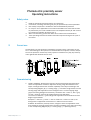 2
2
-
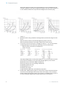 3
3
-
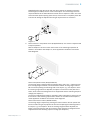 4
4
-
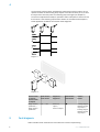 5
5
-
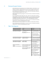 6
6
-
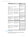 7
7
-
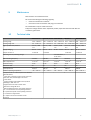 8
8
-
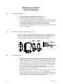 9
9
-
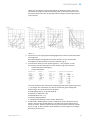 10
10
-
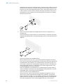 11
11
-
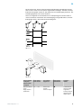 12
12
-
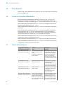 13
13
-
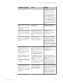 14
14
-
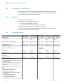 15
15
-
 16
16
-
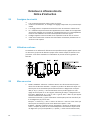 17
17
-
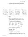 18
18
-
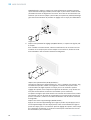 19
19
-
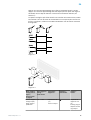 20
20
-
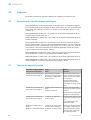 21
21
-
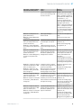 22
22
-
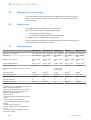 23
23
-
 24
24
-
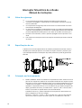 25
25
-
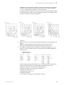 26
26
-
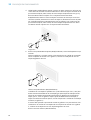 27
27
-
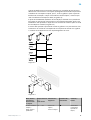 28
28
-
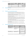 29
29
-
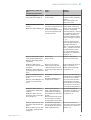 30
30
-
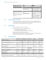 31
31
-
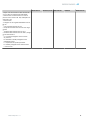 32
32
-
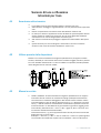 33
33
-
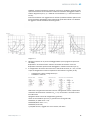 34
34
-
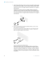 35
35
-
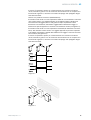 36
36
-
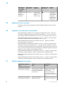 37
37
-
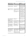 38
38
-
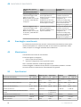 39
39
-
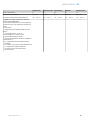 40
40
-
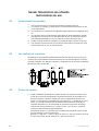 41
41
-
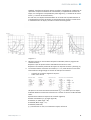 42
42
-
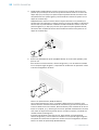 43
43
-
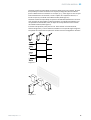 44
44
-
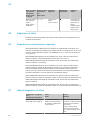 45
45
-
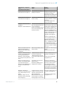 46
46
-
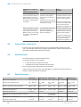 47
47
-
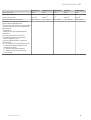 48
48
-
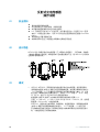 49
49
-
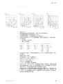 50
50
-
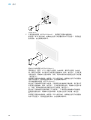 51
51
-
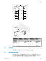 52
52
-
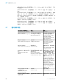 53
53
-
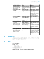 54
54
-
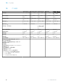 55
55
-
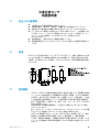 56
56
-
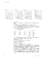 57
57
-
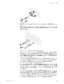 58
58
-
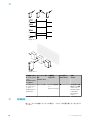 59
59
-
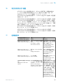 60
60
-
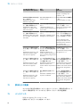 61
61
-
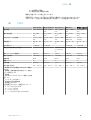 62
62
-
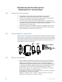 63
63
-
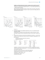 64
64
-
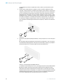 65
65
-
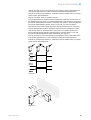 66
66
-
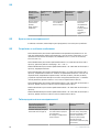 67
67
-
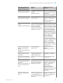 68
68
-
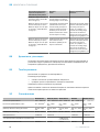 69
69
-
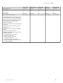 70
70


SICK WTx23-2 Compact photoelectric sensor Instrucciones de operación
- Tipo
- Instrucciones de operación
en otros idiomas
- français: SICK WTx23-2 Compact photoelectric sensor Mode d'emploi
- italiano: SICK WTx23-2 Compact photoelectric sensor Istruzioni per l'uso
- English: SICK WTx23-2 Compact photoelectric sensor Operating instructions
- português: SICK WTx23-2 Compact photoelectric sensor Instruções de operação
- 日本語: SICK WTx23-2 Compact photoelectric sensor 取扱説明書
Artículos relacionados
-
SICK WTx23-2 Compact photoelectric sensor Instrucciones de operación
-
SICK WT100-2 energetic Instrucciones de operación
-
-
-
-
-
-
-
-