Craftsman 152229000 El manual del propietario
- Categoría
- Herramientas eléctricas
- Tipo
- El manual del propietario

struction anu
®
1/2 Horsepower (continuous duty)
1 Horsepower (maximum developed)
12oSpeed, Step Putmey
300 - 3100 R.P.M. Drill Speed Range
1 ILL P
s
C
FOR YOUR OWN SAFETY; Read
and follow all of the Safety and
Operating Instructions before
Operating this DdH Press.
Customer Helpline
1-800-897-7709
PRease have your Model No.
and SedaR No. available.
Sears, Roebuck and Co.
Hoffman Estates, IL 60179 U.S.A.
Part No. 0R93512
EspaSoL pg. 31

SECTION PAGE
Warranty..........................................................................................................................................................................2
ProductSpecifications...................................................................................................................................................3
Safetyinstructions ......................................................................................................................................................... 4
Guidelines for extension cords ..................................................................................................................................... 5
Grounding instructions .................................................................................................................................................. 6
Specific Safety instructions .......................................................................................................................................... 7
Accessories and Attachments ...................................................................................................................................... 8
Know Your Machine ....................................................................................................................................................... 9
Carton Contents ............................................................................................................................................................ 11
AssembJy instructions ................................................................................................................................................. 13
Operations and Adjustment ........................................................................................................................................ 18
Maintenance .................................................................................................................................................................. 26
Troubleshooting Guide ................................................................................................................................................ 27
Part List ......................................................................................................................................................................... 28
EspaSol .......................................................................................................................................................................... 3!
Service information ........................................................................................................................................ Back Page
ONE-YEAR FULL WARRANTY ON CRAFTSMAN TOOL
if this Craftsman tool fails due to a defect in material or workmanship within one year from the date of purchase,
CALL 1=800-4-MY=HOME _)TO ARRANGE FOR FREE REPAIR,
if this tool is used for commercial or rental purposes, this warranty will apply for only ninety days from the date of
purchase,
This warranty applies only while this tool is in the United States,
This warranty gives you specific legal rights, and you may also have other rights, which vary from state to state,
Sears, Roebuck and Co,, Dept 817WA, Hoffman Estates, IL 60179

15°in. Drill Press with Laser°Trac TM
Motor Specifications:
Motor type induction
Continuous duty HP 1/2
Maximum developed HP 1
Amps 8,6
Volts 120
Phase Single
Hertz 60
R,P,M, 1725 (no load)
Product Specifications:
Belt Type
Pulley Type
Belt Tensioning
Number of Speeds
Drill Speeds
Spindle Taper
Chuck Taper
Chuck Type
Chuck capacity
Chuck to Table dimension
Min,
Chuck to Table dimension
Max,
Chuck to Base dimension
Quill Diameter
Quill Travel
Quill Lock
Handle Operation
Motor Control
Poly=V
Step
Sliding motor
12
300, 400, 450, 600, 650,
700, 1100, 1600, 1700,
1900, 2600, 3100
#2 Morse Taper
Jacobs 3
Keyless
0,040" =5/8" (1=16mm)
0 _
24 _
43-3/4"
1-7/8" (47mm)
4"
Yes
360 degree rotation
Toggle with removable
key
Table Size 12" wide x 12" depth
Table Tilt Yes
Table Movement Rack and pinion
Table Material Cast iron
Depth Stop Yes
Depth Stop Type Quick Set
Depth Scab Yes
Column Diameter 2-7/8" (73mm)
Base Work Area 10-1/4" wide x 8-1/4"
depth
Depth of Throat 7=1/2"
Height 67=1/4"
Width 12-1/2"
Depth 27=1/2"
Weight 180 pounds
Convenience:
Light
Laser
Yes, left or right side
mount
Yes
To avoid electrical shock to yourself and damage to the
drill press, use proper circuit protection, Do not expose
to rain, or use in a damp environment,
The drill press is factory wired for 120V, 60 Hz, opera=
tion, Connect to a 120V, 15 amp branch circuit and use
a 15 amp time delay fuse or circuit breaker, The electri=
cal circuit cannot have any wire size less than #14, To
avoid shock or fire, replace power cord immediately if it
is damaged in any way,

GENERAL SAFETY iNSTRUCTiONS
Operating a drill press can be dangerous if safety and
common sense are ignored, The operator must be
familiar with the operation of the tool, Read this manual
to understand this drill press, DO NOT operate this drill
press if you do not fully understand the limitations of
this tool, DO NOT modify this drill press in any way,
REMEMBER: Your personal safety is your responsibility,
BEFORE USUNG THE DF_ULLPRESS
To avoid serious injury and damage to the tool, read
and follow all of the Safety and Operating instructions
before operating the drill press,
1, READ the entire instruction Manual, LEARN how to
use the tool for its intended applications,
2,
ALWAYS WEAR EYE PROTECTION, Any power
tool can throw debris into the eyes during opera-
tions, which could cause severe and permanent
eye damage, Everyday eyeglasses are NOT safety
glasses, ALWAYS wear Safety Goggles (that
comply with ANSi standard Z87,1) when operating
power tools, Safety Goggles are available at Sears
Retail Stores,
3, ALWAYS WEAR HEARING PROTECTION, Plain
cotton is not an acceptable protective device,
Hearing equipment should comply with ANSi
$3,19 Standards,
4, ALWAYS WEAR A DUST MASK TO PREVENT
INHALING DANGEROUS DUST OR AIRBORNE
PARTICLES, including wood dust, crystalline silica
dust and asbestos dust, Direct particles away from
face and body, Always operate tool in well ventilat-
ed area and provide for proper dust removal, Use
dust collection system whenever possible,
Exposure to the dust may cause serious and per-
manent respiratory or other injury, including silicosis
(a serious lung disease), cancer, and death, Avoid
breathing the dust, and avoid prolonged contact
with dust, Allowing dust to get into your mouth or
eyes, or lay on your skin may promote absorption of
harmful material, Always use properly fitting
NIOSH/OBHA approved respiratory protection
appropriate for the dust exposure, and wash
exposed areas with soap and water,
5,
ALWAYS keep the work area clean, well lit, and
organized, DO NOT work in an environment with
floor surfaces that are slippery from debris, grease,
and wax,
6, ALWAYS unplug the tool from the electrical recep-
tacle when making adjustments, changing parts or
performing any maintenance,
7,
8,
9,
10,
11,
12,
13,
14,
15,
16,
17,
18,
19,
AVOID ACCIDENTAL STARTING, Make sure that
the power switch is in the "OFF" position before
plugging in the power cord to the electrical
receptacle,
AVOID A DANGEROUS WORKING ENVIRON-
MENT. DO NOT Use electrical tools in a damp
environment or expose them to rain.
CHILDPROOF THE WORKSHOP AREA by remov-
ing switch keys, unplugging tools from the electrical
receptacles, and using padlocks,
DO NOT use electrical tools in the presence of
flammable liquids or gasses,
DO NOT FORCE THE TOOL to perform an opera-
tion for which it was not designed, it wiii do a safer
and higher quality job by only performing operations
for which the tool was intended,
DO NOT stand on a tool, Serious injury could result
if the tool tips over or you accidentally contact the
tool,
DO NOT store anything above or near the tool
where anyone might try to stand on the tool to
reach it,
DO NOT operate tool if under the influence of drugs
or alcohol,
EACH AND EVERY TIME, CHECK FOR DAMAGED
PARTS PRIOR TO USING THE TOOL. Carefully
check all guards to see that they operate properly,
are not damaged, and perform their intended func-
tions, Check for alignment, binding or breaking of
moving parts, A guard or other part that is damaged
should be immediately repaired or replaced,
GROUND ALL TOOLS, if the tool is supplied with a
3-prong plug, it must be plugged into a 3-contact
electrical receptacle, The 3rd prong is used to
ground the tool and provide protection against
accidental electric shock, DO NOT remove the 3rd
prong, See Grounding instructions,
KEEP VISITORS AND CHILDREN AWAY from the
drill press, DO NOT permit people to be in the
immediate work area, especially when the electrical
tool is operating,
KEEP PROTECTIVE GUARDS IN PLACE AND IN
WORKING ORDER,
MAINTAIN YOUR BALANCE. DO NOT extend
yourself over the tool. Wear oil resistant rubber-
soled shoes. Keep floor clear of debris, grease, and
wax,

20. MAINTAIN TOOLS WITH CARE. Always keep tools
clean and in good working order. Keep all blades
and tool bits sharp.
21. NEVER LEAVE A RUNNING TOOL UNATTENDED,
Turn the power switch to the OFF position, DO
NOT leave the tool until it has come to a complete
stop,
22. REMOVE ALL MAINTENANCE TOOLS from the
immediate area prior to turning the tool ON.
23. SECURE ALL WORK. When it is possibb, use
damps or jigs to secure the workpbce. This is safer
than attempting to hold the workpbce with your
hands.
24. STAY ALERT, watch what you are doing, and use
common sense when operating a power tool. DO
NOT USE a tool wNe tired or under the influence
of drugs, abohol, or medication. A moment of
inattention whib operating power tools may result
in serious personal injury.
25. USE ONLY RECOMMENDED ACCESSORIES.
Use of incorrect or improper accessories could
cause serious injury to the operator and cause
damage to the tool. if in doubt, check the instruction
manual that comes with that particular accessory.
26. USE A PROPER EXTENSION CORD IN GOOD
CONDITION. When using an extension cord, be
sure to use one heavy enough to carry the current
your product will draw. Please see "MiNiMUM
RECOMMENDED GAUGE FOR EXTENSION
CORDS (AWG)" table for correct sizing of an exten-
sion cord. if in doubt, use the next heavier gauge.
27. WEAR PROPER CLOTHING. DO NOT wear loose
clothing, gloves, neckties, or jewelry. These items
can get caught in the machine during operations
and pull the operator into the moving parts. Users
must wear a protective cover on their hair, if the
hair is long, to prevent it from contacting any
moving parts.
GUIDELINES FOR EXTENSION CORDS
The smaller the gauge number, the larger diameter of
the extension cord is. if in doubt of the proper size of an
extension cord, use a shorter and thicker cord. An
undersized cord wiii cause a drop in line voltage result-
ing in a loss of power and overheating. USE ONLY A
3-WIRE EXTENSION CORD THAT HAS A 3_PRONG
GROUNDING PLUG AND A 3-POLE RECEPTACLE
THAT ACCEPTS THE TOOL'S PLUG,
If you are using an extension cord outdoors, be sure
it is marked with the suffix "W°A" ("W" in Canada) to
indicate that it is acceptable for outdoor use.
Be sure your extension cord is properly sized, and
in good electrical condition. Always replace a damaged
extension cord or have it repaired by a qualified person
before using it.
Protect your extension cords from sharp objects,
excessive heat, and damp or wet areas.
120 VOLT OPERATION ONLY
25'LONG 50' LONG 100' LONG
0 to 6 Amps
6 to 10 Amps
10 to 12 Amps
12 to 15 Amps
18 AWG
18 AWG
16 AWG
14 AWG
16 AWG
16 AWG
16 AWG
12 AWG
16 AWG
14 AWG
14 AWG
Not
recommended

THIS TOOL MUST BE GROUNDED while in use to
protect the operator from eUectric shock.
IN THE EVENT OF A MALFUNCTION OR BREAK-
DOWN, grounding provides the path of bast resistance
for eUectriccurrent and reduces the risk of eUectric
shock. This tooUis equipped with an eUectric cord that
has an equipment-grounding conductor and a ground-
ing pDg. The pUugMUST be pDgged into a matching
eUectrbaUreceptacle that is properUy installed and
grounded in accordance with ALL bcaU codes and
ordinances.
DO NOT MODIFY THE PLUG PROVIDED. if it wHUnot
fit the eUectrbaUreceptacb, have the proper eUectrbaU
receptacle installed by a qualified electrician.
IMPROPER ELECTRICAL CONNECTION of the equip°
ment-grounding conductor can result in risk of electric
shock. The conductor with the green insulation (with
or without yellow stripes) is the equipment-grounding
conductor. DO NOT connect the equipment-grounding
conductor to a live terminal if repair or replacement of
the electric cord or plug is necessary.
CHECK with a qualified electrician or service personnel
if you do not completely understand the grounding
instructions, or if you are not sure the tool is properly
grounded.
The motor supplied with your drill press is a 120 volt,
singb-phase motor. Never connect the green wire to a
live terminal.
USE ONLY A 3-WIRE EXTENSION CORD THAT HAS
A 3-PRONG GROUNDING PLUG AND A 3-POLE
RECEPTACLE THAT ACCEPTS THE TOOL'S PLUG.
REPLACE A DAMAGED OR WORN CORD IMMEDI-
ATELY.
This too[ is intended for use on a circuit that has an
electrical receptacle as shown in FIGURE !-1.
FIGURE !-! shows a 3-wire electrical plug and electri-
cal receptacle that has a grounding conductor. If a
properly grounded electrical receptacle is not available,
an adapter as shown in FIGURE 1-2 can be used to
temporarily connect this plug to a 2-contact ungrounded
receptacle. The adapter has a rigid lug extending from
it that MUST be connected to a permanent earth
ground, such as a properly grounded receptacle box.
THIS ADAPTER IS PROHIBITED IN CANADA.
CAUTION: In all cases, make certain the electrical
receptacle in question is properly grounded. If you are
not sure have a certified electrician check the electrical
receptacle.
This Drill Press is for indoor use only, Do not expose to
rain or use in damp locations,
Fig. 1-1
120 Volt
grounding
conductor
3-wire power cord
3-prong
electrical
receptacle
Fig. 1-2
120 Volt
grounding
conductor
3-wire power cord
grounding
2-prong
electrical
receptacle

SPECIFIC SAFETY iNSTRUCTiONS
The operation of any drill press can result in debris
being thrown into your eyes, which can result in severe
eye damage, ALWAYS WEAR EYE PROTECTmON, Any
power tool can throw debris into the eyes during opera-
tions, which could cause severe and permanent eye
damage. Everyday eyeglasses are NOT safety glasses.
ALWAYS wear Safety Goggles (that comply with ANSi
standard Z87.1) when operating power tools. Safety
Goggles are available at Sears Retail Stores.
Basic precautions should always be followed when
using your drill press. To reduce the risk of injury, elec-
trical shock or fire, comply with the safety rubs listed
below:
1. READ and understand the instruction manual
before operating the drill press.
2, AVOmDAWKWARD OPERATmONS AND HAND
POSmTmONS.A sudden slip could cause a serious
injury.
3. CHECK all drill bits, cutting tools, sanding drums, or
other accessories for damage before installing in
the drill press chuck. Damaged items can cause
damage to the drill press and or serious injury.
4. Before leaving the drill press, LOCK or REMOVE
the ON/OFF switch/key to prevent unauthorized
use,
5,
DO NOT install or use any drill bit that exceeds
7-inches in length or that extends 6-inches below
the chuck jaws. The drill bit can suddenly bend or
break.
6. DO NOT try to drill a workpiece that is too small to
be securely held to the table or in a vise.
7. DO NOT operate this drill press until it is assembled
and installed according to the instruction manual.
8. DO NOT leave the drill press plugged into the elec-
trical outlet. Unplug the drill press from the outlet
when not in use and before servicing, changing bits
and cleaning.
9. DO NOT USE router bits, shaper cutters, circle (fly)
cutters, rotary planers or wire wheels in this drill
press.
10. FOLLOW all electrical and safety codes, including
the National Electric Code (NEC) and the
Occupational Safety and Health Regulations
(OSHA). All electrical connections and wiring should
be made by qualified personnel only.
11, LET THE CHUCK REACH FULL SPEED before
starting drill operations,
12. MAKE SURE there are no foreign objects, nails,
stones in the workpiece.
13, NEVER PERFORM LAYOUT, ASSEMBLY OR
SETUP WORK on the table/work area when the
drill press is running.
14, NEVER START THE DRmLLPRESS BEFORE
CLEANmNG THE TABLE OF ALL OBJECTS (tools,
scrap pieces, etc,), Debris can be thrown at high
speed.
l& NEVER START THE DRmLLPRESS with the drill
bit, cutting tool, or sanding drum against the work-
piece. Loss of control of the workpiece can cause
serious injury.
16, OBTAmNADVmCE FROM YOUR SUPERVmSOR,
instructor, or another qualified person if you are not
familiar with the operation of this drill press,
17, PROPERLY SUPPORT long or wide workpiece and
clamp to the table,
18, PROPERLY SECURE the drill bit, cutting tool, or
sanding drum in the chuck before operating the drill
press,
19, REPLACE a damaged cord immediately, DO NOT
use a damaged cord or plug, if the drill press is not
operating properly, or has been damaged, left out-
doors or has been in contact with water, return it to
a Sears Service Center,
20. SECURE the drill press to the floor or work bench.
Vibration can cause the drill press to slide, walk or
tip over.
21. SECURE the workpiece firmly against the table.
Do not attempt to drill a workpiece that does not
have a fiat surface against the table, or that is not
secured by a vise. Prevent the workpiece from
rotating by clamping it to the table or by securing it
against the drill press column. Loss of control of
the workpiece can cause serious injury.
22. SECURELY LOCK the head and table support to
the column, and the table to the table support
before operating the drill press.
23. The drill press is designed for home use or light
commercial duty ONLY.
24, TO REDUCE THE RmSKOF ELECTRmCAL
SHOCK, do not use outdoors, Do not expose to
rain, Store indoors in a dry area,
25, TURN THE DRmLLPRESS OFF and unplug from
power source. Wait for the drill bit, cutting tool, or
sanding drum to come to a complete STOP before
cleaning off the table/work area, removing or secur-
ing workpiece, or changing setup.
26. USE only drill bits, cutting tools, sanding drums, or
other accessories with proper shank size recom-
mended in this instruction manual. The wrong size
shank can cause damage to the drill press and/or
serious injury.

27,USEonlyasdescribedinthisinstructionmanuak
USEaccessoriesonlyrecommendedbySears,
28,USERECOMMENDEDSPEEDSforalloperations,
Otherspeedsmaycausethemachinetomalfunc°
tioncausingdamagetothedrillpressandor
seriousinjury,
29,informationregardingthesafeandproperoperation
ofthistoolisaboavailabbfromthefollowing
sources:
Power Tool institute
1300 Summer Avenue
Cbveland, OH 44115-2851
www, powertoolinstitute,org
National Safety Council
1121 Spring Lake Drive
Itasca, IL 60143-3201
American National Standards institute
25 West 43rd Street, 4th floor
New York, NY 10036
www, anskorg
ANSi 01,1 Safety Requirements for
Woodworking Machines, and the
U,S, Department of Labor regulations
www, osha,cj__
ADDITIONAL SAFETY RULES
FOR THE LASER
1, LASER LIGHT - DO NOT STARE INTO BEAM,
APERTURE, or into a reflection from a mirror-like
surface,
2,
AVOID EXPOSURE - LASER LIGHT IS EMITTED
FROM BOTH SIDES OF LASER ASSEMBLY,
Use of controls or adjustments, or performance of
procedures other than those specified herein may
result in hazardous laser light exposure,
3, DO NOT DISASSEMBLE LASER MODULE, The
laser is a CLASS 11LASER PRODUCT that can
emit laser power up to 1 mW MAX at 635 nm,
which could result in exposure with the module
disassembled, The laser unit complies with 21
CFR 1040,10 and 1040,11,
4, USE OF CONTROLS OR ADJUSTMENTS OR
PERFORMANCE OF PROCEDURES OTHER
THAN THOSE SPECIFIED HEREIN MAY RESULT
IN HAZARDOUS RADIATION EXPOSURE.
AVAILABLE ACCESSORIES
Visit your Sears Hardware Department or see the
Craftsman Power and Hand Tool Catalog for the
following accessories,
ITEM STOCK NUMBER
* Circle Cutter 25293
* Clamping Lit 26426
* 8-in, Vise 24077
* 4-in, Vise 24081
* 3-in, Vise 24071
* 21 pc, Sanding Drum Kit 25262
* 7 pc, Forstner Bit Set 25389
Sears may recommend other accessories not listed in
this manual.
See your nearest Sears Hardware Department or
Craftsman Power and Hand Tool Catalog for other
accessories.
Do not use any accessory unless you have completely
read the instruction Manual for that accessory.
Use only accessories recommended for this drill press.
Using other accessories may cause serious injury and
cause damage to the drill press.

Figure 2-1
f jf_J_
----3
J
9J F
V
1, BeHtcover
2, Feed handHes
3, ON/OFF switch
4, KeyHess chuck
5, CoHumn
6, TaMe
7, Base
8, AdjustabHe depth stop
9, Motor
O, Work Light
_4__------5
6
is

Figure 2-2 11 Figure 2-3
13
12
11, Light switch
12, Left feed handb hub
13, BeUttension bck knob
14, Belt tension lock knob
15, Belt tensioning handle
16, Light mounting hobs, right side
17, Laser (not shown)
18, Quill lock
19, Removable key
Figure 2-4 Figure 2-5
22
23
/
21
20
20, Table raise/lower handle
21, Table rotation lock handle
10
22, Table bevel scab
23, Table height lock handle

UNPACKUNG AND CHECKUNG CONTENTS
This drill press wiii require some amount of assembly,
Remove all of the parts from the shipping box and lay
them on a clean work surface,
Remove any protective materials and coatings from all
of the parts and the drill press, The protective coatings
can be removed by spraying WD°40 on them and
wiping it off with a soft cloth, This may need redone
several times before all of the protective coatings are
removed completely, CAUTmON: DO NOT use acetone,
gasoline or lacquer thinner to remove any protective
coatings on your drill press,
After cleaning, apply a good quality automotive wax to
any unpainted surfaces, Make sure to buff out the wax
before assembly,
Compare the items to figures below; verify that all items
are accounted for before discarding the shipping box,
if there are any missing parts, call Customer Helpline
1°800°897°7709,
The drill press is a heavy machine, two people may
be required to unpack and lift machine,
if any parts are missing, do not attempt to plug in the
power cord and turn ON the drill press, The drill press
can only be turned ON after all the parts have been
obtained and installed correctly,
Figure 3-1
A
)
C
D
A, Column, table support, rack and ring
B, Drill press head and motor assembly
C, Table
D, Work light
E, Base
11

Figure 3-2
W
G
H
V
K
L
N
P
O
R Feed handHe(3)
G, Hex head screw MIO X 40mm (4)
H, TaMe raise/Hower handHe
H, TaMe height HockhandHe
J, TaMe rotation HockhandHe
K, Hex wrench 5mm
L, Hex wrench 3mm
M, Hex wrench 2,5mm
N, SpindHeadapter remover
O, KeyHess chuck
P, Chuck arbor
Q, Lock washer M6 (2)
R, Hex socket head screw M6 x 16mm (2)
S, Adhesive cord champ (2) (not shown)
T, Cord sHeeve
U, Cord champ
V, CHamp
W, Laser assembHy
12

TOOLS REQUIRED
The following toob are needed for assembly and align-
ment, Note: Hex wrenches are provided, The remaining
toob are typbal shop tools and are not included with
your drill press,
17mm Open end wrench , Straight screwdriver
Hammer and block of wood • Combination square
The drill press is a heavy machine; two peopb may
be required for certain assembly operations,
DO NOT assembb the drill press until you are sure
the tool is unplugged,
DO NOT assembb the drill press until you are sure
the power switch is in the "OFF" position,
For your own safety, DO NOT connect the drill press
to the power source until the machine is completely
assembled and you read and understand the entire
Instruction Manual,
COLUMN, BASE AND TABLE ASSEMBLY
Figure 4-1 r----
I
I
I
[
I
B
\ ' i'i
C
Attach the column (A) to the base (B) using the four
MIO x 40mm hex head screws (C), two of which
are shown, See Figure 4-1,
13
Figure 4-2
F
B
2,
Attach the table raising and lowering handle (D) on
the worm gear shaft (E), Make sure to position the
set screw (F) over the fiat (G) on the worm gear
shaft and tighten the set screw, See Figure 4-2,
Figure 4-3
K
3,
Assemble the threaded end (H) of the table height
lock handle (I) into hob (J) in the rear, left side of
the table support (K), Note: The table height lock
handle is the larger of the two lock handles, See
Figure 4-3,

Figure 4-4 DRILL PRESS HEAD AND
MOTOR ASSEMBLY
O
K
* The ddH press is a heavy machine; two peopb may
be required for certain assemMy operations,
* MAKE CERTAIN the ddH press is disconnected from
the power source,
Figure 5-1
A
4, Assembb the threaded end of the tame rotation
bck handb (L) into hoUe(M) in the front, right side
of the tame support, Do not compbteUy tight handb
at this time, Note: The tame rotation bck handb
is the smaller of the two bck handbs,
See Figure 4-4,
Figure 4-5
N
B
1, Seat the ddH press head (A) on the coUumn (B),
See Figure 5-1
Figure 5-2
D
K
5,
insert the tame (N) into the mounting hole (0) table
support (K), Rotate the table to desired position
and tighten table rotation locking handle, See
Figure 4-4 and 4-5,
2, Align the drill press head with the table and base,
Tighten the two head locking screws (C), See
Figure 5-2
3, Thread the three pinion shaft handles (D) in the
three tapped hobs located in the pinion shaft (E),
14

Figure 5-3 Figure 5-5
\
zj _
G F
H
N
NOTE: Make certain that the chuck arbor (F) and the
tapered hoUein the chuck (G) are dean and free of
grease, Uacquer,or rust preventive coatings, See
Figure 5-3, HousehoUd oven cleaner can effectiveUy
remove any substance from the spindUe and chuck,
Carefully follow the manufacturer's safety ruUescon-
cerning its use,
4, Open the chuck jaws completeUy, hoUdthe top collar
(H) and turn the chuck barreU(U)counter-clockwise,
Make sure the jaws are compUeteUyrecessed inside
the chuck, See figure 5-3,
Figure 5-4
7, Hace cord sUeeve (M) onto Hght cord (N), See
Figure 5-5,
Figure 5-6
0
5, Seat the chuck onto the chuck arbor as far as it wHU
go,
6, Carefully drive the chuck and chuck arbor into the
ddH press spindUe (J), Hace a wooden Mock (K)
under the chuck and tap the Mock up with a
hammer (L), See Figure 5-4,
CAUTION: DO NOT tap directly on the chuck with a
metal hammer,
8, Place cord clamp (0) over cord sleeve and attach
the light assembly to the drill press with two M6 x
16mm hex socket head screws and lock washers
(P), See Figure 5-6,
NOTE: The light assembly can be mounted on either
side of the drill press,
15

Figure 5-7 Figuce 6°2
©
D
F
E
C
9,
Position the adhesive cord champs (Q) onto drHi
press so that they wHi keep the Hightcord dear
of the working area of your drHi press,
See Figure 5-7,
LASER ASSEMBLY
2, Remove battery cover (C) from Maserhousing,
3, Connect a 9-voit battery (D) (not inciuded) to
battery termina] (E),
4, Piace battery into battery compartment (F) and
repiace battery cover,
MAKE CERTAIN the drill] press is disconnected from
the power source,
LASER LIGHT - DO NOT STARE INTO BEAM,
APERTURE, or into a reflection from a mirror-Hike
surface,
Figure 6-3
Figure 6-1
\
Piace champ (A) through openings (B) in iaser
housing,
5,
6,
Place laser around column (G) and against the
head casting (H) and fasten the clamp securely at
the column,
Make sure laser housing is positioned that one
laser is to each side of the head casting,
16

FASTENING DRILL PRESS
Figure 7ol
A
A
A
To help reduce the tendency of the drill press to tip
over, slide, or walk, it can be fastened to the floor
surface, The machine base has four hobs (A), one at
each corner where it can be fastened (hardware not
included), See Figure 7=1,
17

DONOTexposetheddflpresstorainoroperatethe
indampbcations,
MAKESUREaftpartshavebeenassembbdcorrectly
andareinworkingorder,
2,
With the switch toggb removed, the switch wHUnot
operate, However, shouUd the switch toggb be
removed while the ddfl press is operating, the
switch can stHUbe turned OFF, but cannot be
restarted without inserting the switch toggb,
SWITCH OPERATION
Figure 8-1
FLEXUBLE LAMP
To reduce the risk of fire, use 40 watt or bss, 120 voUt,
reflector track-type fight buUb(not supplied), DO NOT
use a standard househoUd fight buUb,The reflector track-
type Hght buUbshould not extend below the lamp shade,
Figure 9-1
B
The switch (A) is located on the front of the drift press
head, See Figure 8-1, To turn the drift press ON, move
the switch up, To turn the drift press OFF, move the
switch down,
Figure 8-2
© ©
\
\
\
\,
IMPORTANT: When the machine is not in use, the
switch should be locked in the OFF position to prevent
unauthorized use,
1, Grasp the switch toggle (B) and puff it out of the
switch, See Figure 8-2,
The flexible lamp (A) operates independently of the drift
press and has its own power cord, To turn the lamp ON
and OFF, rotate the switch (B) in the clockwise direction
only, See Figure 9-1,
CAUTION: The flexible lamp housing wiii remain hot for
a few minutes after turning it OFF, Avoid contact with
housing until it is cool,
18

TABLE OPERATION Figure 10-3
Figure 10-1
B
C
J
1, To raise or lower the table (A) on the column (B),
loosen the table height lock handle (C), See Figure
10-1 and 10-2,
/
5, The table can be tilted right or left by removing the
table alignment pin (F), See Figure 10-3,
NOTE: if the pin (F) is difficult to remove, turn the nut
(G) clockwise to pull the pin out of the casting,
Figure 10-2
A
D
Figure 10-4
H
2, Turn the table raising and lowering handle (D)
clockwise will raise the table and counter-clockwise
will lower the table, See Figure 10-2,
3, After the table is at the desired height, tighten the
table height lock handle,
NOTE: Always raise (rather than lower) the table to the
final position to allow the gears to mesh and prevent
slippage,
4, The table (A) can be rotated 360 degrees by loos-
ening the table rotation lock handle (E) and rotating
the table to the desired position, and tightening the
table clamp, See Figure 10-2,
NOTE: For thru-drilling operations, make sure the table
center hob is aligned with the drill bit,
6, Loosen the table locking bolt (H) and tilt the table to
the desired angle, and tighten the table locking bolt,
See Figure 10-4,
7,
A tilt scab (I) is provided on the table bracket cast-
ing to indicate the degree of tilt, A witness line (J) is
provided on the table to align with the tilt scab,
See Figure 10-1,
NOTE: When the table is returned to the level position,
replace the table alignment pin, This wiii position the
table surface 90 degrees to the spindle,
See Figure 10-3,
19

DRULL SPEEDS
MAKE CERTAIN the drill press is disconnected from the power source,
Twelve drill speeds (300, 400, 450, 600, 650, 700, 1100, 1600, 1700, 1900, 2600 and 3100 RM) are available with
your drill press, See Figure 11=1to select the correct spindle speed for your operation, This diagram can also be
found on the inside of the belt cover of the drill press,
Figure 11-1
Recemmended Dri|| Press Speeds
Size 1Seftwo0d1HardwoodI Acrylic I Brass 1 Alum 1Steem
TwistDrillBits
!/16" - 3/10"
1/4" - 3/0"
7/16" - 5/6"
!1/!6" - 1"
BradPeint}}its
1/6" - 1/4"
3/6"
1/2"
5/8"
3/4"" 7/8"
ForstnerBits
!/4" - 5/8"
3/4"- 1"
1-!/8" - 1-1/4"
!o3/8" - 2"
3100
3100
1600
790
3100 2600 3100 3100 3100
1660 1900 1100 2600 1100
700 1660 790 1600
450 NR 400 1!00 300
1900
1900
1000
1900
1600
1100
1t00 1600 NR NR NR
700 1600 NR NR NR
700 1100 NR NR NR
600 790 NR NR NR
300 660 NR NR NR
300 390 NR NR NF_
2@0
1600
1!00
600
600 300 NR NR NR
450 300 NR NR NR
300 300 NR NR NR
360 NR NR NR NR
NR = HOT RECOMMEND6_;
_P|NDLE MOTOR
300
400
450
600
600
"ZOO
_P|NDLE MOTOR
1100
16OO
1700
1900
2600
3100
CHANGING SPEEDS AND
ADJUSTING BELT TENSUON
MAKE CERTAIN the drill press is disconnected from
the power source,
Figure 12-1
A
E
/
1, Open the belt cover (A), See Figure 12=1,
2 Loosen the tension lock knobs (B), one is on each
side,
3, Rotate the belt tension handle (C) forward, away
from the motor (D),
4, Position both belts (E) on selected pulleys accord=
ing to the drill speed diagram,
5, Rotate the belt tension handle back, towards the
motor to apply tension on the belts,
NOTE: The belt should be just tight enough to prevent
slipping, Excessive tension will reduce the life of the
belt, pulleys and bearings, Correct tension is obtained
when the belt can be flexed about 1" out of line midway
between the pulleys using light finger pressure,
6, Tighten both tension lock knobs,
B
2O

DF_ULUNG HOLES TO DEPTH Figure 14-1
MAKE CERTAIN the drill press is disconnected from
the power source,
Figure 13-1
1. insert the ddH bit into the keybss chuck and tighten.
2. Hace the workpbce on the ddH press tame. Raise
the ddH press tame until the workpbce is 1/8qn.
from the ddH bit.
NOTE: Make sure the workpbce is secured to the tame
properly,
3, Turn the two knurled stops (A) on the thread depth
scab (B) until the bottom stop is aligned with the
dimension you want to drill on the scab (C),
4. Tighten the top stop against the bottom stop. This
wHUkeep the stops from moving during drHHng
operations.
5. DdH a test hob to check the depth.
NOTE: For thru-drHHng operations, make sure the tame
center hob is aligned with the drill bit,
ADJUSTING RETURN SPRING
The drill chuck will automatically return slowly to its
upper position when the handle is released. The return
spring was properly adjusted at the factory. However, to
adjust, if necessary:
MAKE CERTAIN the drill press is disconnected from
the power source,
1. Loosen and remove the hex nut inside of the left
hub (A).
Figure 14-2
E
21
2, Slide hub (A) of shaft (D), Make sure that the
spring housing (B) remains engaged with head
casting (C), See Figure 14-1 and 14o2,
3,
While firmly holding the spring housing (B) pull the
spring housing out and rotate it (counter-clockwise
to increase or clockwise to decrease the spring
tension) until the boss (E) is engaged with the next
notch (F) on the spring housing, See Figure 14-2,
iMPORTANT: The return spring is under tension, it wiii
want to unwind (clockwise), Make sure you have a firm
hold of the spring housing before pulling it out,
4. Replace hub hex nut onto shaft. Tighten nut com-
pletely then back off 1 turn.

LASER ADJUSTMENTS Figure 15-3
MAKE CERTAIN the drill press is disconnected from
the power source,
• LASER LIGHT - DO NOT STARE INTO BEAM,
APERTURE, or into a reflection from a mirror-like
surface,
Figure 15-1
J
i
_--C
1, Install alignment pin (A) into chuck (B), make sure
that the pointed end (C) of the alignment pin is
down, See Figure 15-1,
Figure 15-2
F
6, Loosen the two screws (U)on the face (J) of the left
side laser, See Figure 15-3,
7, On the alignment pin (A) there is a vertical line (L)
scribe into it, This is used to set parallelism of the
lasers, See Figure 15-4,
8, Using knob (K), rotate the laser beam until it is
exactly on the vertical line (L) on the alignment pin,
The chuck and alignment pin may need to be rotat-
ed to allow the laser beam to fall onto the vertical
line, See Figure 15-3 and 15-4,
9, Tighten screws (I), making sure the laser beam
does not move off the vertical line (L), See Figure
15-3 and 15-4,
Figure 15-4
G
H
2, Turn the laser ON with the rocker switch (D) on the
left side of the laser housing, See Figure 15-2,
3, With the 2,5mm hex wrench (E), loosen the screw
(F) in the top, left side of the laser housing,
4, Using knob (G) located on the underside of the
laser housing, rotate the laser beam (H) until it is
close to center on the alignment pin (A),
5, Tighten screw (F), making sure the laser beam
does not move off the alignment pin,
L
f .......
10, Repeat STEPS 2 through 9 to setup the right side
laser,
22

Figure 15-5 iNSTALLiNG AND REMOVING DRILL BiTS
O
\
D
M
MAKE CERTAIN the drill press is disconnected from
the power source,
Figure 16-1
11, Adjust the drill press table so that it is about
1" under the alignment pin,
12, Lay a 3/4" piece of wood (M) onto the drill press
table under the line pin, See Figure 15-5,
13, Using the drill press feed handle, lower the align=
merit pin down and mark (N) the wood, Make sure
the wood does not move, See Figure 15-5,
14, Loosen the screw (F) in the top, left side of the
laser housing and using knob (G) located on the
underside of the laser housing, rotate the laser
beam (0) until crosses mark (N) in the wood,
See Figure 15=2and 15-5,
15, Tighten screw, making sure the laser beam does
not move off the mark,
16, Repeat STEPS 14 and 15 to set the right side laser,
17, Move the wood about 1" and mark it again, check-
ing that the mark is position where the two laser
beams cross, if it does not repeat STEPS 13
through 16 above,
1,
2,
3,
4,
5,
Hold the collar (A) and turn the chuck barrel (B)
counter=clockwise to close the chuck jaws and
clockwise to open the chuck jaws, See Figure 16=1,
Open the chuck jaws slightly larger than the
diameter of the drill bit
insert the smooth end of drill bit in the chuck as far
as it wiii go, and then back the bit out 1/16" (or up
to the beginning of the drill bit flutes),
Center the drill bit in the chuck before tightening
the chuck,
To securely tighten the bit in the chuck, hold the
collar (A) with one hand and with the other hand
tighten the barrel (B) counter=clockwise, See
Figure 16=1,
NEVER run drill press to install or tighten a drill bit or
cutter in the keyless chuck,
23

SUPPORTING WORKPIECE
USE only recommended accessories,
Figure 17-1
QUILL LOCK
The quill allows the up and down movement of the
chuck, Different setup or working operation may
require the quill to be lower and locked into position,
Figure 18-1
C
A
IMPORTANT: When the workpiece (A) is long enough,
position it on the table with one end against the left
side of the column (B) to prevent the workpiece from
rotating, See Figure 17-1, if it is not possible to
support the workpiece against the column, clamp the
workpiece to the table, A vise can be used to secure a
small workpiece that is too small to be clamped to the
table, The vise must be secured to the table to keep it
from rotating, if you are using a backup board, it must
also be properly supported or clamped,
B
Lower quill (A) to desired depth and tighten quill locking
handle (B), The quill locking handle is spring loaded
and can be repositioned by pulling out on the hub (C)
and rotating it, See Figure 18-1,
To unlock the quill, hold onto the feed handle and
loosen the quill locking handle, The quill is spring
loaded and wiii return back up into the drill press head
casting, Be sure to hold onto the feed handle to control
the speed in which the quill returns,
24

CORRECT DRiLLiNG SPEEDS
Factors that determine the correct speed are: the work-
piece, the size of the hoUe,the type of bit or other cutter,
and the quality of cut wanted,
Use the recommended speed for the ddH bit and work-
piece.
DRiLLiNG WOOD
Twist drill bits, usually intended for metaUdrHHng,can
aUsobe used for boring hoUesin wood. However, brad
point or Forstner bits are generally preferred for working
in wood. These bits cut a fiat bottom hoUeand are
designed for removaUof wood chips. Do not use hand
bits which have a screw tip or auger bits. At drill press
speeds, they will Hftand rotate the workpiece.
For through boring, align the table so that the bit will go
through the center hole. Scribe a vertical line on the
front of the column and a matching mark on the table
bracket and the drill press head, so that the table and
drill press head can be clamped in the center position
at any height.
Feed the bit slowly when it is close to cutting through
the wood to prevent splintering the bottom face. Use a
scrap piece of wood as backup under the workpiece.
This helps to reduce splintering and protects the point
of the bit.
DRULUNG METAL,
ALUMINUM OR BRASS
NEVER hold the workpiece in your bare hands.
ALWAYS use clamps or vises to hold your workpiece.
Twist drill bits should only be used in drilling metals.
Never hold the workpiece in your bare hands; always
use clamps or vises. The drill bit may seize the work at
any time, especially when breaking through the work-
piece. If the workpiece is whirled out of the operator's
hand, the operator may be injured. The drill bit will be
broken if the workpiece strikes the column.
The workpiece must be clamped or securely held in a
vise while drilling. Any tilting, twisting, or shifting results
not only in a rough hole, but also increases drill bit
breakage. For flat work, lay the workpiece on a wooden
base and clamp it firmly down against the table to pre-
vent it from turning. If the workpiece is of irregular
shape and cannot be laid flat on the table, it should be
securely blocked and clamped.
When drilling metal, it will be necessary to lubricate the
tip of the drill bit with oil to prevent it from overheating.
DRILUNG OPERATION
Use a center punch to dent the workpiece where you
want the hole. This will keep the bit from walking when
you start the drill operation. Before turning the drill
press ON, turn the laser ON and align the cross-hairs
with center mark on the workpiece. Make sure the
workpiece is properly supported or secured to the table.
For thru-drilling, make sure the table center hole is
aligned with the drill bit. Turn the drill press ON and
start to feed the drill chuck down with the feed handles.
FEEDING TOO RAPIDLY may cause the belt or drill bit
to slip or break, the motor to stall, the workpiece to pull
loose from the table, Never try to rush your work; allow
the drill press to work smoothly,
25

CHANGmNG LASER BATTERY
Turn the power switch OFF and unplug the power
cord from its power source,
LASER UGHT - DO NOT STARE mNTOBEAM,
APERTURE, or into a reflection from a mirror-like
surface,
Figure 19-1
F
Turn the power switch OFF and unplug the power cord
from its power source,
The drill press has sealed lubricated bearings in the
motor housing that do not require any additional lubrica-
tion from the operator,
The quill and spindle assemblies should be periodically
lubricated, Lower the quill assembly and squirt or wipe
a thin film of lightweight machine oil on the entire sur-
face, Place a few drops of light machine oil down the
spindle assembly, Raise and lower the quill several
times to distribute the oil evenly,
1, Remove batter'},,cover (A) from laser housing,
2, Remove the 9-volt battery from the battery compart-
ment (B),
3, Disconnect the 9-volt battery (C) from battery
terminal (D),
4, Connect a new 9-volt battery (not included) to
battery terminal,
5, Place battery back into battery compartment and
replace battery cover,
NOTE: The battery is a 9-volt standard alkaline battery
(not included), When replacing the battery, the battery
terminals should be thoroughly cleaned, Use a soft
paintbrush or similar device, to remove all sawdust and
debris,
CLEANING
With the drill press unplugged, blow off motor with low-
pressure air to remove dust or dirt, Air pressure above
50 P, S, I, should not be used as high-pressured air
may damage insulation, The operator should always
wear eye protection when using compressed air,
Do not use a shop vacuum to clean metal shavings,
The metal shavings can cause an explosion or fire,
Do not allow chips and dust to accumulate under drill
press, Keep area clean and in safe order,
CAUTION: DO NOT USE FLAMMABLE MATERIALS
to clean the drill press,
After cleaning, apply a good quality automotive wax to
any unpainted surfaces, Make sure to buff out the wax
before assembly,
ONLY trained personnel should perform repairs to the
drill press, Contact your nearest Sears Service Center
for authorized service, Unauthorized repairs or replace-
ment with non-factory parts could cause serious injury
to the operator and damage to the drill press,
26

TOPREVENTINJURYTOYOURSELFordamagetotheddHpress,turntheswitchtotheOFFpositionandunpUug
thepowercordfromtheeUectrbaUreceptaclebeforemakinganyadjustments,
PROBLEM
Motor does
not start or
does not come
up to full
speed
Motor stalls or
circuit breakers
open frequently
Motor running
too hot
Drill bit stalls
or slips
DrH_bit or
matedam
smokes or
burns
E×cessive drill bit
runout or wobbme
UKELY CAUSE(S)
1. Switch key is removed.
2. Defective switch.
3. Defective capacitor.
4. Low line voltage.
5. Defective motor.
1. Circuit overload.
2. Low line voltage.
3. Motor overload.
4. incorrect fuses on circuit breakers.
5. Short circuit in motor; loose connections
or worn insulation on lead wires.
1. Restricted air circulation due to dust
accumulation.
2. Motor overload.
1. Belt is incorrectly tensioned.
2. Drill bit is not securely tightened in
chuck.
1. incorrect spindle speed.
2. Chips not exiting out of drill hole.
3. Dull drill bit.
1. Bent drill bit.
2. Drill bit not properly installed in chuck.
SOLUTION
1. insert switch key.
2. Have switch replaced.
8. Have capacitor replaced.
4. Correct !ow line voltage condition, if machine is
plugged into an extension cord, disconnect and plug
directly into wall outlet.
5. Have motor replaced.
NOTE: #3 and #4 must be done by a qualified service
technician; Consult Sears service.
1.
2.
3.
4.
Reduce circuit load (turn off other appliances).
Correct low line voltage condition. Check line voltage
with a multi-meter, if the machine is plugged into an
extension cord, unplug it from the extension cord and
plug directly to the wail outlet.
Reduce load on motor, slow down feed rate.
Have correct fuses on circuit breakers installed by a
qualified electrician.
inspect terminals in motor for damaged insulation and
shorted wires and have them replaced. Check all
power lead connections.
1. Clean dust and restore normal air circulation around
motor.
2. Reduce load on motor, slow down feed rate.
1.
2.
Adjust belt tension. See changing speeds and adiusting
belt tension in "OPERATIONS AND ADJUSTMENTS".
install drill bit properly. See installing and removing drill
bit in "OPERATIONS AND ADJUSTMENTS".
1.
2.
3.
Reduce spindle speed. See speed diagram on the
underside of the belt cover.
Retract drill bit frequently during drilling operation to
clear chips from hob.
Replace or sharpen drill bit.
1. Replace with a straight or new drill bit.
2. install drill bit properly. See installing and removing drill
bit in "OPERATIONS AND ADJUSTMENTS".
Spindle returns too 1. Return spring has incorrect tension. 1. Adjust spring tension. See adjusting spindle return
slow or too fast spring in "OPERATIONS AND ADJUSTMENTS".
Chuck will not
stay onto spindme
1. Grease, dirt or oil on spindle taper or
in chuck taper.
1. Clean grease, dirt or oil off of spindle taper and chuck
taper. See drill press head and motor assembly in
"ASSEMBLY iNSTRUCTiONS".
27

15-in.DrillPress MODELN0.152.229000
Whenservicing,useonlyCRAFTSMANreplacementparts,UseofanyotherpartsmaycreateaHAZARDorcause
productdamage,
Anyattemptto repairorreplaceelectricalpartsonthis
techniciandoesrepairs,RepairserviceisavailableatyournearestSearsServiceCenter,
drillpressmaycreateaHAZARDunlessaqualifiedservice
AlwaysorderbyPARTNUMBER,notbykeynumber,
KEY PART KEY PART
NO. NO. DESCRiPTiON QTY. NO. NO. DESCRiPTiON
Depth Scale
Knurl nut
Mounting Bracket
M6x12mm Flat Hd Screw
Ring
M6x8mm Hex Soc Set Screw
Table Bracket Assy incl, (88,89,90,91,92,93,94,95)
Shaft
Pinion Gear
M16x35mm Hex Hd Screw
Thread Pin
1/4-20 Hex Nut
Scale
5ram Drive Screw
Indicator
5ram Drive Screw
Table
Rack
Base
M8x125mm Hex Hd Screw
M8,4 Flat Washer
M&I Lock Washer
M8 Hex Nut
MlOx4Omm Hex Rd Screw
Column Assy incl, (106)
M10x12mm Hex Soc Set Screw
M6xlOmm Nex Soc Set Screw
Handle Assy
Lock Handle Assy (Table)
Worm Gear
Lock Handle Assy (Column)
3ram Hex Wrench
2.5mm Hex Wrench
5ram Hex Wrench
Light Assy incl, (116)
Light Warning Label
Light Cord Clamp
M6x16mm Hex Soc Hd Screw
M6mm Lock Washer
Cord Clamp
Cord Sleeve
Motor incl, (123, 125)
Motor Cord
Motor Spec Label
M6xlOmm Nex Soc Set Screw
Motor Pulley
Key
Belt (J27)
Spindle Pulley Nut
Spindle Pulley
M12 x 1,75 Lock Nut
1/2" Lock Washer
Motor Bracket
Motor Tension Rod (R.H.)
Motor Tension Rod (L,H.)
M8 Hex Nut
M8.4 Flat Washer
M8x2Omm Hex Hd Screw
Eccentric
Center Pulley
Ball Bearing 6202
Belt (J25)
Power Cord
Tie wire
Laser Assy const of
(150,151,152,153,154155,156,157,158,159,160)
M4x14mm Hex Soc Hd Screw
M3x14mm Hex Soc Hd Screw
Top Cover
Main Housing
Switch
Holder
Lasermodule Assy
Hose Clamp
Alignment Pin
Door
Laser Warning Label
Owner's Manual (Not Shown)
0R92300 Pulley Cover Assy const of, (1,2,3,4,5,6,7,8,9) 1 80 0R93505
1 0R92301 Upper Pulley Cover 1 81 0R92302
2 0R92304 Bottom Pulley Cover 1 83 0R92356
3 0R91774 M4xlOmm Cheese Hd Screw 4 84 0R93531
4 0R90078 M4 Hex Nut 4 85 OR92362
5 0R90431 M4.3 Ext Tooth Washer 4 86 0R93552
6 0R93451 Speed Chart 1 87 0R92363
7 0R93541 M3 5x9.5mm Pan Hd Tap Screw 4 88 0R92365
8 0Rg2382 Nameplate 2 89 0R92364
9 0R93542 M4,2xg.5mm Pan Hd Tap Screw 1 90 0R93545
10 0R90241 M6x12mm Cheese Hd Screw 4 91 0R92699
11 0R90059 M6,4 Flat Washer 4 91A 0R90071
12 0R92305 Sleeve 1 92 0R92367
13 0R92306 Retaining Ring 1 93 0R92728
14 0R90366 Ball Bearing 6204 1 94 0R92366
15 0R92307 Spacer 1 95 0R92728
16 0R90366 Ball Bearing 6204 1 96 0R92371
17 0R92306 Retaining Ring 1 98 0R92373
0R93549 Pinion Assy const of, (18,20,21) 1 99 0R92374
18 0R92333 Pinion 1 100 0R92725
20 0R92334 Hub (R.H,) 1 101 0R91499
21 OR92721 M5x2Omm Spring Pin 1 102 QR90248
22 0R92332 Handle 3 103 0R90307
23 0R92331 Knob 3 104 0R93546
24 0R93523 Ext Ret Ring 1 105 0R92372
25 0R92330 Tension Handle 1 106 0R93524
26 0R90310 M8x16mm Hex Hd Screw 1 107 0R90222
27 0R92328 Eccentric 1 108 0R92369
28 0R92329 Pin 1 109 OR92370
29 0R92327 Foam Washer 4 110 0R92416
30 OR90382 M5x16mm Cheese Hd Screw 1 111 0R92368
31 0R92324 Clamp 1 112 0R90290
32 0R93524 MlOx12mm Bex Soc Set Screw 2 113 0R90289
33 0R93548 M6x24mm Spring Pin 2 114 0R93547
34 OR92326 Lock Screw 2 115 0R92375
35 0R92323 Headstock incl, (36,37,38,39) 1 116 0R91317
36 0R93504 Serial Number Label 1 117 0R92377
37 0R92728 5ram Drive Screw 4 118 OR91758
38 0R92325 Warning Label 1 119 0R90502
39 0R92728 5ram Drive Screw 2 120 0R92376
40 OR90228 MIO Hex Nut 1 121 0R92487
41 0R90647 3/8" Lock Washer 1 122 0R92316
42 0R92335 Special Screw 1 123 0R92320
43 0R92336 Lock Handle 1 125 0R93507
45 OR92341 Switch Box 1 126 0R90222
46 0R90382 M5x16mm Cheese Nd Screw 2 127 OR92313
47 0R90362 M5,3 Ext Tooth Washer 4 128 0R92312
48 0R90507 M5xSmm Pan Hd Screw 2 129 0R92308
49 0R93543 M5x28mm Pan Hd Screw 2 130 0R92315
50 0R92342 Insulator 1 131 0R92314
51 0R92343 Switch Cover 1 132 0R93550
52 0R90716 M4,2x12mm Pan Hd Tap Screw 2 133 0R93539
53A 0R90037 Switch incl (53B) 1 134 0R92317
53B OR90038 Key 1 135 0R92318
55 0R92359 Chuck 1 136 OR92319
56 0R92358 Arbor 1 137 0R90307
57 0R92357 Spindle 1 138 OR91499
58 0R93544 Ball Bearing 6205 1 139 0R90308
60 0R93533 M6x45mm Hex Hd Screw 1 140 0R92311
61 0R90306 M6x12mm Hex Soc Set Screw 1 141 0R92310
62 0R92350 Stop Collar 1 142 0R90075
63 0R93550 M12 x 1.75 Lock Nut 1 143 0R92309
64 0R90235 M6 Hex Nut 1 144 0R92321
65 0R92349 Spindle Adapter Remover 1 145 OR92322
66 0R92348 Quill 1 0R92428
67 0R92347 Rubber Washer 1
68 0R90218 Ball Bearing 6203 1 150 0R92717
69 0R92346 M17,5 Flat Washer 1 151 0R92718
70 0R92345 Ring 1 152 0R92711
71 0R92344 Nut 1 153 0R92712
72 0R92337 Spring Retainer 1 154 OR92713
73 0R92338 Spring Assy 1 155 0R92715
74 0R92379 Special Flat Washer 1 156 0R92716
75 0R92339 Hub (L,H.) 1 157 0R92709
76 0R92340 Plate 1 158 0R92710
77 OR90304 M12.4 Flat Washer 1 159 0R92714
78 0R93551 M12 x 1.5 Lock Nut 1 160 0R92731
79 0R92351 Depth Rod incl, (8@ 1 161 0R93512
QTY.
1
2
1
2
1
1
1
1
1
1
1
1
2
1
2
1
1
1
4
8
4
4
4
1
1
1
1
1
1
1
1
1
1
1
1
2
2
2
1
1
1
1
1
1
1
1
1
1
1
2
2
1
1
1
4
8
4
1
1
1
1
1
2
1
2
6
1
1
1
2
2
1
1
1
2
1
28

15qn. Drill Press MODEL NO.152.229000
150 (2)
152---_f
[
155 (2) -_
%% "_158
I57
95 (2}\
93
I04
103 <4)-_
102 <"_) _
Ioo
75 \
84 <2>,
45
//57
(4>
(2>
52
(4)
(4)
29

30

®
1/2 Caballo de Fuerza (servicio continuo)
1 Cabailo de Fuerza (ma×imo desarrollado)
12 Veiocidades, Polea Escalonada
Gama de VeJocidades de Perforaci6n
300-3100 R.P.M
J
f
Mode_o No.
152.229000
C
PARA SU SEGURJDAD PERSONAL, Reay
obedezca todas Uaslnstrucciones de
Seguddad y Operaci6n antes de operar
esta Taladradora de Banco
15
ii 15
i_ iii
Linea de Ayuda al CLiente
1-800-897-7709
Sirvase tenor listo su
No. de Modelo y No. de Sede
Sears, Roebuck and Co.
Hoffman Estates, JL 60179 U.S.A.
No. de Pieza OR93512
31

SECO[ON PAG[NA
Garant_a.........................................................................................................................................................................32
Especificacionesde[producto....................................................................................................................................33
[nstruccionesdeseguridad.........................................................................................................................................34
Directricespara[ase×tensiones e[_ctricas ............................................................................................................... 35
[nstrucciones de cone×i6n a tierra ............................................................................................................................. 36
[nstrucciones de seguridad especfficas .................................................................................................................... 37
Accesorios y aditamentos ........................................................................................................................................... 38
Conozca su m&quina .................................................................................................................................................. 39
Contenido de [a caja .................................................................................................................................................... 41
[nstrucciones de montaje ............................................................................................................................................ 43
Operaciones y aiuste ................................................................................................................................................... 48
Mantenimiento .............................................................................................................................................................. 56
Guia de [oca[izaci6n de averias .................................................................................................................................. 57
Listado de piezas .......................................................................................................................................................... 58
[nformaci6n de $ervicio .......................................................................................................................... Contraportada
GARANTiA COMPLETA DE UN ANO PARA LAS HERRAMIENTAS CRAFTSMAN
Siesta herramienta Craftsman Ibgase a failar debido a defectos materiabs o de elaboraci6n dentro de un aho a partir de la
fecha de compra, LLAME AL 1-800-4-MY*HQME @ (en EE,UU,) PARA CQQRDINAR LA REPARACION GRATUITA,
Si se utiliza esta herramienta con fines comereiaies o de alquiler, esta garant[a se aplicara por s6io noventa d[as a partir de la
fecha de compra,
Esta 9arantfa se apliea s61o mientras que esta herramienta se encuentre en los Estados Unidos,
Esta garantfa le concede derechos bgabs espeeifieos, y tambien podrb_tenet otros derechos que var[an de un estado al otto,
Sears Roebuck and Co, Dept 817 WA, Hoffman Estates, iL 60179
32

Taladradora de Banco de 15 pu_g° con
Laser-Trac TM
_ecificaciones det Motor:
Tipo de motor Inducci6n
Servic[o continuo 1/2 HP
Maximo desarrollado 1 HP
Amperios 8.6
Voltios 120
Fase Monofb_sico
Hertzios 60
R.RM. 1725 (sin carga)
_ecificaciones deI Producto:
Tipo de correa
Tipo de polea
Tensi6n de correa
NOmero de vetocidades
Velocidades de perforaci6n
Ahusado de[ huso
Ahusado del mandrino
Tipo de mandrino
Capacidad del mandrino
Dimensi6n mandrino a mesa,
rain.
Dimensi6n mandrino a mesa,
max.
Dimensi6n mandrino a base
Diametro deI arbol hueco
Recorrido del arbol hueco
Cierre del arboI hueco
Operaci6n de agarradera
Control del motor
DJmensJones de mesa
Poly "V"
Escalonada
Motor desJJzante
12
300, 400, 450, 600, 650,
700, 1100, 1600, 1700,
1900, 2600, 3100
Ahusado Morse #2
Jacobs 3
Sin Ilave
0.040-5/8 pulg. (1-16 ram)
0 pulg.
24 pulg.
49-3/4 pulg.
1-7/8 pulg. (47 ram)
4 pulg.
S[
Rotaci6n a 360 grados
Interruptor de palanca con
IJave desmontable
12 pulg. de ancho x
12 pulg. de profundidad
Inclinaci6n de mesa
Movimiento de mesa
Material de mesa
Tope de profundidad
Tipo de tope de profundidad
Escala de profundidad
Diametro de columna
Zona de trabajo basica
Profundidad de garganta
Alto
Ancho
Profundidad
Peso
S[
Cremailera y pi[i6n
Hierro moldeado
Sf
Quick-Set
S(
2-7/8 pulg. (73 mm)
10-1/4 pulg. de ancho x
8-1/4 pulg. de profundidad
7-1/2 pulg.
67-1/4 putg.
12-1/2 putg.
27-1/2 putg.
180 libras
Conveniencia:
Luz
Laser
S[, montaje en el costado
[zquierdo o derecho
S[
Use la protecci6n adecuada de circuitos para evitar los
choques electricos y e! da_o a la taladradora. No Ia exponga
a la Iluvia ni haga uso de ella en entornos h0medos.
La taladradora viene cableada de fb_bricapara el funciona-
miento a 120 V, 60 Hz. Conectela a un circuito de derivaci6n
de 120 V, 15 amperios y utilice un fusible de retardaci6n de
tiempo o un disyuntor de circuitos de 15 amperios. El circuito
electrico no podra tener un tamaho de alambre inferior al #14.
Para evitar choques electricos o incendios, reponga el cord6n
de energia tan pronto como quede dahado de cuatquier
manera.
33

INSTRUCCIONES GENERALES
DE SEGURIDAD
El uso de una taIadradora puede ser peligroso si se hace
caso cruise de la seguridad y el sentido comon. El operario
debe estar famifiarizado con et funcionamiento de esta herra-
mienta. Lea este manual para entender esta taladradora. NO
OPERE esta taladradora si no entiende plenamente las Iimita-
ciones de esta herramienta. NO MODIFIQUE este taIadradora
de ninguna manera. REOUERDE: Su seguridad personal es
su responsabiiidad.
ANTES DE HACER USO
DE LA TALADRADORA
Lea y obedezca todas las instrucciones de Seguridad y
Operaci6n antes de operar la taladradora para evitar hendas
graves y daRo a la herramienta.
1. LEA el Manual de Instrucciones cabalmente. APRENDA
como usar la herramienta para su aplicaci6n propuesta.
2. UTILICE PROTECCION OCULAR SlEMPRE. Cualquier
herramienta mecanica puede expuIsar escombros hacia
los ojos durante Ias operaciones, causando daRo ocular
grave y permanente. Los anteojos de use cotidiano NO
son gafas de seguridad. Utiiice gafas de seguridad (que
cumplan con la normativa Z87.1 de ANSb StEMPRE
cuando vaya a operar herramientas mec_inicas. Las
gafas de seguridad estg,n disponibles en las tiendas de
Ventas al Detal de Sears.
3. UTILICE PROTECCION AUDmVA SlE_,_PRE. El algo-
d6n por sf solo no constituye un dispositivo de protecci6n
aceptable. El equipo auditNo debe eumplir con las
normativas S3.19 de ANSI.
4. UTJUCE SlEMPRE UNA CARETA CONTRA EL POLVO
PARA EVITAR ASPIRAR POLVOS PEUGROSOS O
PART_CULAS EN EL AtRE, incluyende polvo de madera,
pelvo de sflice cdstalino y polvo de asbesto. Didja las
partfcuias en direcci6n opuesta a! rostro y ei cuerpo.
Opere la herramienta siempre en una zona bien ventilada
y proporcione Ia remoci6n apropiada de! polvo. UtiIice un
sistema de recolecci6n de polvo siempre que sea posF
ble. La exposici6n al polvo puede ocasionar dares respi-
ratodos graves y permanentes u otras heridas, inciuyen-
do silicosis (una enfermedad pulmonar grave), cancer y
la muerte. Evite aspirar el polvo y evite e! contacto pro-
Iongado con el polvo. El permitir Ia entrada deI polvo en
su boca u oios, o deiar que permanezca sobre su pieI,
puede promover la absorci6n de material daRino. Utilice
protecci6n respiratoria aprobada per NIOSH/OSHA, de
ajuste correcto y apropiada para la exposici6n ai polvo, y
lave Ias zonas expuestas con iab6n y agua.
5. Mantenga Ia zona de trabaio limpia, bien iIuminada y
organizada EN TODO MOMENTO. NO trabaje en un
entomo con superficies de piso resbalosas debido a los
escombros, grasas y cera.
6. Desenchufe la herramienta del tomacorrientes SIEMPRE
que vaya a reaiizar cuaIquier ajuste, recambio de piezas
o Ilevar a cabo cuatquier tarea de mantenimiento.
34
7. EVITE LOS ARRANQUES ACCIDENTALES. Aseg0rese
de que el interrupter de energ[a se encuentre en la posi-
ci6n de "OFF" (apagado) antes de enchufar el cord6n de
potencia y causar dare a la herramienta.
8. EVITE UN ENTORNO DE TRABAJO PEUGROSO. NO
utilice Ias herramientas electricas en entornos h0medos
ni las exponga a la Iluvia.
9. HAGA SU TALLER A PRUEBA DE NINOS al quitar las
Ilaves de los interruptores, desenchufando Ias herramien-
tas de sus tomacorrientes y usando candados.
10. NO utilice herramientas electricas en la presencia de
I[quidos o gases inflamables.
11. NO FUERCE LA HERRAMiENTA a realizar una
operaci6n para la que no fue diseRada. Realizarb, un
trabajo m_s seguro y de mayor calidad s61o efectuando
aqueilas operaciones para las que fue diseRada.
12.
13.
14.
15.
NO se pare sobre la herramienta. Esto podrfa resultar en
heridas graves si la herramienta se vuelca o si usted
hace contacto accidental con la herramienta.
NO almacene nada sobre o cerca de Ia herramienta
deride alguien pueda intentar pararse sobre la herra-
mienta para alcanzarto.
NO opere la herramienta si se encuentra bajo la infiuen-
cia del alcohol o de las drogas.
EN TODA Y CADA OCAS_0N, REVISE SJ EXtSTEN
PIEZAS DANADAS ANTES DE OPERAR LA HERRA-
MIENTA. Revise todos los protectores cuidadosamente
para asegurarse de que funcionen correctamente, que no
esten daRados, y que realicen sus funciones destinadas.
Revise la alineaci6n y busque Ia atascadura o ruptura de
todas las piezas en movimiento. Un protector, una pieza
de inserci6n u otra pieza daRada debe repararse y susti-
tuirse inmediatamente.
16. CONECTE TODAS LAS HERRAMIENTAS A TIERRA.
Si Ia herramienta viene equipada con un enchufe de tres
roaches, se Ie debe enchufar en un tomacorrientes de
tres contactos. El tercer macho se utiliza para conectar la
herramienta a tierra y ofrecer protecci6n contra !os
cheques electricos accidentales. NO quite ei tercer
macho. Ver Instrucciones de Conexi6n a Tierra.
17. MANTENGA ALEJADOS A LOS VISITANTES Y NtNOS
de la taladradora. NO permita que haya gente en la zona
inmediata de trabajo, sobre todo cuando Ia herramienta
electrica se encuentre en funcionamiento.
18.
19.
20.
MANTENGA TODOS LOS PROTECTORES EN SUS
SITIOS Y EN BUENAS CONDICIONES DE TRABAJO.
MANTENGA SU EQUILIBRIO, NO se extienda sobre la
herramienta. Utilice calzado con suetas de caucho y
resistentes al aceite. Mantenga el piso despejado de
escombros, grasas o cera.
MANTENGA SUS HERRAMIENTAS CON CUIDADO.
Mantenga sus herramientas limpias yen buen estado de
funcionamiento siempre. Mantenga filosas todas las
hoias y las brocas.

21.NUNCADEJEUNAM_,QU_NAENFUNCJONAM_ENTO
SiNATENDERApagueelinterrupterdeenerg[aaIa
posici6nde"OFF"(apagado).NOsealejedeJamb,quina
hastaquesehayadetenidopercompbto.
22.RETIRETODASLASHERRAMJENTASDEMANTEN_-
M_ENTOdeIazonainmediataantesdeENCENDERla
herramienta.
23.AFJANCETODOELTRABAJO.Cuandoseaposible,
hagausedeabrazaderasopJantilbsparaposicionar
paraafianzareEmateriakEstoresuitam_.sseguroque
intentarsqetarelmaterialconsusmanes.
24.MANT¢:NGASEALERTA,mireIoqueestahaciendoy
tengasentidocomuncuandovayaahacerusedeuna
herramientamecanica.NOUT_UOEunaherramienta
cuandoestecansadonibajoIaJnfiuenciadedrogas,
alcoho!omedicamentos.Unmementodeinatenci6n
duranteetusedeherramientasmecb,nicaspuederesultar
enheridaspersonabsgraves.
25.SOLOUTJLJCELOSACCESOR_OSRECOMENDADOS.
Etusodeaccesoriosincorrectosoindebidospuede
resultarenheridasgravesaIoperarioycausardafioala
herramienta.SJtienedudas,consulteelmanualde
instruccionesquevieneconeseaccesorioenparticular.
26.UTIUCEUNAEXTENSKSNEL¢:CTRJCAENBUEN
ESTADQCuandovayaahacerusodeunaextensi6n
el6ctrica,aseguresedeutilizarunaqueseaIosuficiente-
mentepesadacomoparaportarIacorrienterequerida
persuproducto.TengalabondaddevereJcuadro
"CALIBRESM[NIMOSRECOMENDADOSPARALAS
EXTENSIONESELE_CTRICAS(AWG)"paraeldimen-
sionamientocorrectodeunaextensi6nelectrica.Sitiene
dudas,utiliceelpr6ximocalibremaspesado.
27.UTJLJCELAVESTJMENTACORRECTA.NOutiliceropa
holgada,guantes,corbatasniartfcu!osdejoyerfa.Estos
artfculospuedenquedaratrapadosenlamaquina
duranteIasoperacionesyarrastraraloperariohaciaIas
piezasenmovimiento.ElusuariodebeIlevarunacubier-
taprotectivasobresucabelIo,sitienecabellolargo,para
proteger!ocontraelcontactoconcuaJquierpiezaen
movimiento.
DIRECTRJCES PARA LAS
EXTENSUONES ELECTRICAS
Mientras menor sea el n0mero de calibre, mayor sera el
diametro de la extensi6n electrica. Si tiene dudas sobre las
dimensiones correctas de una extensi6n electrica, utilice una
extensi6n mas corta y gruesa. Una extensi6n de tama_o
reducido producira un baj6n en Ia tensi6n de linea, resultando
en la perdida de energ!a y el sobrecalentamiento. USE SOLO
UNA EXTENSION ELECTR_OA DE TRES ALAMBRES CON
ENCHUFE DE CONEX_6N A TJERRA DE TRES MACHOS Y
UN RECEPTACULO DE TRES MACHOS QUE ACEPTE EL
ENCHUFE DE LA HERRAM_ENTA.
Siva a hacer uso de aria e×tension eBectrica a maintemo
perie, este seguro de que este marcado con el sufijo "W-A"
("W" en Canadb,) para indicar que es aceptable para el use a
Jaintemperie.
Est_ seguro de que su e×tensi6n em_ctrica tenga mas
dimensiones correctas y este en buen estado de funciona-
miento. Reponga siempre una extensJ6n el6ctrica daSada o
haga que una persona competente Ja repare antes de hacer
use de ella.
Proteja sus extensiones em_ctricae contra los objetos
fHosos, el caJor excesivo y los Jugares hOmedas o mojadas.
FUNCIONAMIENTO A 120 VOLTIOS SOLAMENTE
0 to 6Amperios
6 to !0 Amperios
10 to 12Amperios
12 to 15Amperios
25 PIES DE
LARGO
18AWG
18AWG
16AWG
14AWG
50 PIES DE
LARGO
16AWG
16AWG
16AWG
12AWG
100 PINESDE
LARGO
16AWG
14AWG
14AWG
No se
recomienda
35

ESTA HERRAMIENTA DEBE ESTAR CONECTADA A
TJERRA durante el uso para proteger al operario contra los
choques eI6ctficos.
EN EL CASO DE UN MALFUNCJONAMJENTO O AVERJA, ia
conexi6n a tierra ofrece ei trecho de menor resistencia para la
corriente electrica y reduce el riesgo de choque el6ctrico.
Esta herramJenta viene equipada con un cord6n de energ_a
que tiene un conductor de conexi6n a tierra del equipo y un
enchufe de conexi6n a tierra. El enchufe DEBE estar enchu-
fado a un tomacorrientes que coincida con el mismo y este
conectado a tierra en conformidad con TODOS Josc6digos y
ordenanzas en el ambito Jocak
NO MODJFIQUE EL ENCNUFE SUM_NJSTRADO. Si no cabe
en e! tomacorrientes existente, haga que un electrJcista
competente instale eJtomacorfientes apropiado.
LA CONEXJ6N ELECTRJCA _NCORRECTA del conductor de
conexi6n a tierra dei equipo puede resultar en el peligro de
choques electricos. El conductor con el aJslante verde (con o
sin rayas amarillas) es et conductor de conexi6n a tierra del
equipo. NO conecte el conductor de conexi6n a tierra del
equipo a una terminaci6n con corriente si se requiere Ia
reparaci6n o el reemplazo deJ cord6n de energ[a o deJ
enchufe.
CONSULTE con un electricista competente o personaI de ser-
vicio si no entiende completamente Ias instrucciones de
conexi6n a tierra, o si no est_ seguro si Jaherramienta se
encuentra debidamente conectada a tierra.
El motor suministrado con su TaJadradora es un motor
monofAsico de 120 voltios. Jamas conecte eJalambre verde a
una terminaci6n con corriente.
USE SOLO UNA EXTENSKSN EL¢:CTRICA DE TRES HJLOS
CON ENCHUFE DE CONEXJ6N A TIERRA DE TRES
MACNOS Y UN RECEPTACULO DE TRES MACNOS QUE
ACEPTE EL ENCNUFE DE LA NERRAMJENTA.
REPONGA CUALQUIER CORDON DANADO O GASTADO
tNMEDJATAMENTE.
Esta herramienta est,. diseBada para el uso en un circuito
que tiene un tomacorrientes conforme a Io iJustrado en Ja
FIGURA 1-1. La FIGURA 1-4 muestra un enchufe el6ctrico de
3 alambres y tomacorrientes con conductor de conexi6n a
tierra. Si no hay un tomacorrientes disponible, puede hacerse
uso provisional de adaptador como el que aparece en Ia
FJGURA 1-2 para conectar este enchufe temporalmente a un
tomacorrientes de 2 contactos que no este conectado a tJerra.
El adaptador dispone de una orejeta rigida que se extiende
deI mismo y que DEBE estar conectado a una conexi6n a
tierra permanente, taI como un tomacorrientes debidamente
conectado a tierra. ESTE ADAPTADOR ESTA PRONJBJDO
EN CANADA.
PRECAUCION: Asegurese en todos los casos de que el
tomacorrientes en cuesti6n este debidamente conectado a
tierra. Si no est_ seguro, haga que un eJectricista competente
revise el tomacorrientes.
Utilice esta taladradora s6io bajo techo. No la exponga a Ja
JJuviani Jautilice en entornos h0medos.
Figura 1-1
120 Vo_tios
conductor de
conexi6n a tierra
enchufe de energia de 3 alambres
\
tomacorrientes
de 3 machos
Figura 1-2
120 Vo_tios
oreieta del
adaptador de
conexi6n a tierra
conductor de (_'_
conexi6n a tierra
tomacorrientes
de 2 machos
enchufe de energia de 3 alambres
36

INSTRUCCIONES ESPEC[FICAS
DE SEGURJDAD
El uso de cuatquier taladradora puede expulsar escombros
hacia los ojos durante Ias operaciones, Io que puede causar
dane ocular grave y permanente. UTJLICE PROTECCKSN
OCULAR SJEMPRE. El use de cuaiquier herramienta
mecanica puede expulsar escombros durante ias opera-
ciones, Io que puede causar dane ocular grave y permanente.
Los anteojos cotidianos NO son gafas de seguridad. Utilice
Gafas de Seguridad (que cumplan con la normatJva Z87.1 de
ANSH)SlEMPRE cuando vaya a operar herramientas mecani-
cas. Las gafas de seguridad estan disponibles en las tiendas
de Ventas al DetaJ de Sears.
Deben seguirse ciertas precauciones basicas durante el uso
de su taJadradora. Para reducir el riesgo de heridas, cheques
eIectricos o [ncendios, cumpIa con las reglas de seguridad
que aparecen a continuaci6n:
1. LEA y entienda el manual de instrucciones antes de
operar esta herramienta mecanica.
2. EVJTE LAS OPERACIONES Y POSICJONES DE MANO
TORPE& Un desliz repentino puede resultar en heridas
graves.
3. REWSE todas las brocas, herramientas de corte, tam-
bores de lijado u otros accesorios antes de instaladas en
el mandrino de la taIadradora per si existen seRales de
daRo. Los art[cuJos daRados pueden producir dane a la
taladradora y/o heridas graves.
4. Antes de alejarse de la taladradora, ClERRE CON CAN-
DADO o DESMONTE el interrupter / Ilave de ENCENDI-
DO / APAGADO para evitar el uso desautorizado.
5. NO [nstale ni use cuatquier broca que sobrepase las
7 puIgadas de largo o que se extienda a 6 pulgadas per
debajo de Ias mandibulas del mandrino. La broca podra
torcerse y romperse repentinamente.
6. NO [ntente perforar un material que sea demasiado
pequeRo para ser firmemente afianzado a la mesa o con
una prensa.
7. NO opere esta taladradora hasta que este montada e
[nstalada conforme al manual de instrucciones.
8. NO deje la taladradora enchufada al tomacorrientes.
Desenchufe la taladradora dei tomacorrientes cuando no
se encuentre en uso, y antes de[ servicio, recambie las
brocas y reaJice la limpieza.
9. NO USE brocas recortadoras, cortadoras limadoras,
cortadoras circulares (volantes), cepilladoras rotativas
o ruedas de alambre con esta taladradora.
10. OBEDEZCA todos los c6digos electricos y de seguridad,
[ncIuyendo el C6digo Electrico Nacional (NEC) y los
Reglamentos de Seguridad y Salud en el Trabajo
(OSHA). Todas las conexiones y cabIeado deben ser
realizadas per personaJ competente soIamente.
11. PERMITA QUE EL MANDRINO ALCANOE VELOCIDAD
PLENA antes de comenzar las operaciones de per-
foraci6n.
12. ASEGORESE de que no existan objetos extraRos, clavos
n[ piedras en el material.
13. JAM.&S REAUCE LABORES DE TRAZADO, ENSAM-
BLADO O MONTAJE sobre Ia mesa / zona de traba]o
cuando la maquina este funcionando.
14. JAM,&S ARRANQUE LA TALADRADORA SiN ANTES
HABER DESPEJADO TODOS LOS OBJETOS DE LA
MESA (herramientas, trozos de material descartado,
etc.). Los escombros podran ser expulsados a alta
velocidad.
l& JAMAS ARRANQUE LA MAQUJNA con la broca, la
herramienta de corte o el tambor de lijado contra el
materiak La p@dida de control del material puede resuI-
tar en heridas graves.
16. ASESORESE CON SU SUPERVISOR, instructor u otra
persona capacitada si no esta famiIiarizado con las
operaciones de esta taladradora.
17. APOYE CORRECTAMENTE Ios materiales largos o
anchos y sujetelos a Ia mesa con abrazaderas.
18. AFJANCE CORRECTAMENTE la broca, Ia herramienta
de corte o el tambor de Iijado en el mandrino antes de
operar la taladradora.
19. REPONGA cualquier cord6n daRado [nmediatamente.
NO utJlice un cord6n o enchufe daRado. Si la taladradora
no funciona correctamente, o si se ha daRado, dejado a
la [ntemperie o entrado en contacto con agua, devuelvala
a un centre de servicio Sears.
20. AFIANCE Ia taladradora al sueIo o a un banco de traba-
jo. Las vibraciones pueden hacer que la maquina se
deslice, camine o se vuelque.
21. ANANCE el material firmemente contra Jamesa. No
[ntente perforar un material que no tenga una superficie
pIana contra Ia mesa, o que no este afianzada con un
torn[llo de banco. Hmpidaque el material gire abrazandoIo
a la mesa o afianzandoIo contra la columna de la prensa.
La p@dida de controI sobre el material puede resuItar en
heridas graves.
22. ENCLAVE e! apoyo del cabezal y de la mesa a la colum-
na firmemente, y la mesa aJapoyo de la mesa, antes de
operar la taladradora.
23. La taladradora esta diseRada para el uso domestico o el
use comercial Jigero SOLAMENTE
24. PARA REDUCJR EL PEUGRO DE LOS CHOQUES
EL¢:CTRICOS, no use la herramienta a la intempede. No
la exponga a la Iluvia. Almacenela bajo techo.
25. APAGUE LA TALADRADORA y desench0fela de la
fuente de energ[a. Espere a que Ia broca, herramienta de
corte o tambor de l[]ado dejen de girar antes de Iimpiar la
mesa/zona de trabajo, retirar o asegurar e! material, o
cambiar el montaje.
26. USE s61o brocas, herramientas cortantes, tambores de
lijado u otros accesorios con el tamaRo de espiga
recomendada en este manual de servicio. El accesorio
de tama[io [ncorrecto puede ocasionar dane a la taJa-
dradora y/o heridas graves.
27. SOLO utilice esta maquina de acuerdo con este manual
de instrucciones. SOLO utilice los accesorios recomen-
dados per Sears.
37

28. UT[LICE LAS VELOC[DADES RECOMENDADAS para
todas las operaciones. Otras velocidades podran causar
el malfuncionamiento de la mAquina, causando daf_o a la
taladradora y/o heridas graves.
29. INFORMAOI6N ADJCJONAL acerca deI funcionamiento
seguro y correcto de este producto est,4 disponible de
parte de las siguientes fuentes:
Power Tools institute
1300 Summer Avenue
Cleveland OH 44115-2851
Nationai Safety Council,
1121 Spring Lake Drive
Itasca, IL 60143-3201
American National Standards institute
25 West 43rd Street 4th floor
New York, NY 10036
ANSi 01.1, Requisitos de Seguridad para
Maquinas de Ebanisterfa, y los reglamentos
del Departamento del Trabajo de los EE.UU.
30. GUARDE ESTAS iNSTRUCCJONES. Refierase a elias
frecuentemente y util_celas para capacitar a otros
usuarios.
REGLAS ADICIONALES DE SEGURIDAD
PARA EL LASER
1. LUZ LASER - NO MiRE EL HAZ, LA APERTURA ni
tampoco el refiejo de una superficie espejada.
2.
EV_TE LA EXPOSIC_0N - LA LUZ LASER SE EMITE
DESDE AMBOS LADOS DEL ENSAMBLADO DEL
LASER El uso de controles o ajustes o Ia realizacidn de
procedimientos ajenos a los especificados aquf pueden
resultar en una exposici6n azarosa a la luz IAser.
3.
NO DESMONTE EL MODULO LASER. EI laser es un
PRODUCTO LASER CLASE Hcapaz de emitir potencia
laser hasta 1 mW MAx. a 635 ram, Io que puede resultar
en exposici6n si se desmanteta el m6dulo. La unidad
laser cumple con 21 CFR 1040_10 y 1040_11_
4. EL USO DE CONTROLES O AJUSTES O LA
REALIZACION DE PROCED_MJENTOS AJENOS A LOS
ESPECIFICADOS AQUi PUEDEN RESULTAR EN UNA
EXPOSICION AZAROSA A LA RADJACION.
ACCESORIOS DUSPONIBLES
Visite su Departamento de Ferreteffa Sears o consulte el
CatAIogo de Herramientas Manuales y Mecanicas de
Craftsman para los siguientes accesorios:
ART_CULO NO. DE EXISTENCJA
*Cortadora de Circulos 25293
*Estuche de Abrazaderas 26426
*Tornillo de Banco de 8 pulg. 24077
*Tornillo de Banco de 4 pulg. 24081
*Tornillo de Banco de 3 pulg. 24071
*Estuche de Tambor de Lijado de 21 piezas 25262
*Coniunto de Brocas Forstner de 7 piezas 25389
Sears podra recomendar otros accesorios que no estan lista-
dos en este manual.
Consulte con su Departamento de Ferreter[a Sears mas cer-
cane o su Catalogo de Herramientas Manuales y Mecanicas
de Craftsman para otros accesofios.
No haga use de ning0n accesorio a menos que haya Iefdo
cabalmente el Manual de Instrucciones para dicho accesorio.
S61o ut[lice accesorios recomendados para esta taladradora.
EI uso de cualquier otro accesorio podra ocasionar heridas
graves y producir dare la taladradora.
38

Figura 2+1
f jf_J_
----3
J
9J F
V
1+ Cubierta de la correa
2+ Agarraderas de alimentaci6n
3+ hterruptor de ENCENDHDO/APAGADO
4+ Mandrino sin Ilave
5+ Columna
6+ Mesa
7+ Base
8+ Tope de profundidad ajustable
9+ Motor
10+ Luz de trabajo
4__-_ 5
6
+5
+
39

Figura 2-2 11 Figura 2-3
13 12
11. interrupter de luz
12. Cube de la agarradera de alimentaci6n izquierda
13. Perilla de cierre de tensi6n de correa
14. Perilla de cierre de tensi6n de correa
15. Agarradera de tensi6n de correa
16. Agujeros de montaje de luz, lade derecho
17. LAser (no ilustrado)
18. Cierre del _irbol hueco
19. Llave desmontable
Figura 2-4 Figura 2-5
22
23
/
21
20
20. Agarradera de izado/bajado de mesa
21. Agarradera de cierre de rotaci6n de mesa
22. Escala de biselado de mesa
23. Agarradera de cierre de altura de mesa
4O

DESEMPAQUE Y COTEJO
DEL CONTENIDO
Esta taladradora necesitara cierta cantidad de montaje. Quite
todas Ias piezas de la caja de env[o y col6queias sobre una
superficie de trabajo limpia.
Quite todos Ios materiales y revestimientos protectivos de las
piezas. Los revestimientos protectivos pueden quitarse
rociando WD-40 sobre una pieza y frotandola con un paho
suave. Podra ser necesario repetir eI proceso varias veces
antes de poder quitar todos los revestimientos protectivos
completamente. PREOAUCION: NO utiIice acetona, gasolina
o diIuyente de laca para quitar los revestimientos protectivos
de su taladradora.
Despues de Ia limpieza, aplique una cera automotriz de
buena calidad sobre todas las superficies sin pintar.
Asegurese de frotar la cera para eliminada antes dei montaje.
Compare los art[culos con la Figura 3-1 abajo y compruebe
que todos los art[culos esten contabilizados antes de descar-
tar Ia caja de envio. Si faltan piezas, comun[quese con la
L[nea de Ayuda al Cliente aI 1-800-897-7709.
La taladradora es una maquina pesada. Podrb_n requerirse
dos personas para desembaJar y levantar la m_.quina.
o Si fakan piezas, no intente enchufar el cord6n de energ[a y
encender la taIadradora. La tatadradora s6!o debe encen-
derse despues de haber obtenido todas las piezas y de
habedas instatado correctamente.
Figura 3-1
A
C
)
D
A. Columna, soporte de mesa, cremalIera y anillo
B. Ensamblado del cabezal de la taladradora y el motor
C. Mesa
D. Luz de trabajo
E. Base
41

Figura 3-2
W
G
H
V
K
L
N
P
O
F= Agarradera de alimentaci6n (3)
G= TorniIIo de cabeza hexagonal M10 x 40 mm (4)
H= Agarradera de izado/bajada de mesa
L Agarradera de cierre de altura de la mesa
J= Agarradera de cierre de rotaci6n de la mesa
K= Mave hexagonal 5 mm
h Mave hexagonal 3 mm
M= Mave hexagonal 2=5 mm
N= Desmontador del adaptador del huso
O= Mandrino sin Ilave
P= Arbol del mandrino
Q= Arandela de cierre M6 (2)
R= TornilIo de cabeza hueca hexagonal M6 x 16 mm (2)
S= Abrazadera de cord6n adhesivo (2) (no ilustrado)
T= Camisa del cord6n
U= Abrazadera del cord6n
V= Abrazadera
W= Ensamblado laser
42

HERRAMIENTAS REQUERIDAS
Se requieren Ias siguientes herramientas para el montaje y
alineaci6n. Aviso: Se proporcionan las !laves hexagonales.
Las herramientas restantes son herramientas t[picas de taller
que no estan incluidas con su taladradora.
oLlave de boca de 17 mm _Destornillador recto
Martillo y bloque de madera _Escuadra de combinaciones
o La taladradora es una mb,quina pesada. Podr_n requerirse
dos personas para desembalar y Ievantar Ia mgquina.
NO INTENTE montar la taladradora hasta que este seguro
de que la herramienta est,. desenchufada.
NO INTENTE montar la taladradora hasta que este seguro
de que el interruptor de energ[a esta en la posici6n de
"APAGADO".
o Para su propia seguridad, NO CONECTE la taladradora a la
fuente de energ_a hasta que ia maquina este completa-
mente montada y usted haya le[do y entendido el manual
de instrucciones cabalmente.
MONTAJE BE LA COLUMNA, BASE Y MESA
Figura 4-1 ¢---
I
I
I
[
I
\ ' i'i
C
Conecte la columna (A) a Ia base (B) con los cuatro
tornilIos de cabeza hexagonal M10 x 40 mm (C), dos de
los cuales se ilustran aquf. Ver la Figura 4-1.
43
Figura 4-2
F
2.
Conecte la agarradera de izado y bajada de la mesa (D)
sobre el eje del engranaje heIicoidal (E). Asegurese de
posicionar eI tornillo de fijaci6n (F) sobre la parte plana
(G) dei eje del engranaje helicoidal y apriete el tornillo de
fijaci6n. Ver la Figura 4-2.
Figura 4-3
K
3.
Monte el extremo roscado (H) de la agarradera de
cierre de altura de mesa (I) en el agujero (J) en el lado
posterior izquierdo deI apoyo de mesa (K). Aviso: La
agarradera de cierre de altura de mesa es Ia mayor de
las dos agarraderas de cierre. Ver la Figura 4-3.

Figura 4-4 MONTAJE DEL CABEZAL DE LA
TALADRADORA Y MOTOR
O
K
o La taladradora es una mgquina pesada. Podran requerirse
dos personas para desembalar y levantar la maquina.
o ASEGORESE de que Ia taladradora este desenchufada de
la fuente de alimentaci6n.
Figura 5-1
A
4.
Coloque el extreme roscado de la agarradera de cierre
de rotaci6n de mesa (L) a traves del agujero (M) en el
lade delantero derecho det soporte de la mesa. No
apdete la agarradera del todo en este momento. Aviso:
La agarradera de cierre de rotaci6n de mesa es Iamb, s
pequeSa de las dos agarraderas de cierre. Ver la
Figura 4-4.
Figura 4-5
N
B
1. Asiente el cabezal de la taladradora (A) sobre la columna
(B). Vet la Figura 5-1.
Figura 5-2
D
K
5.
hserte la mesa (N) al agujero de montaje (O) del soporte
de la mesa (K). Gire Ia mesa a la posici6n deseada y
apnete la agarradera de cierre de rotaci6n de mesa.
Ver la Figura 4-4 y 4-5.
D
2. Alinee el cabezal de la taladradora con Ia mesa y Ia
base, y apriete los dos tornillos de cierre del cabezal (C).
Ver Ia Figura 5-2.
3. Enrosque Ias tres agarraderas del eje del pi56n (D) en los
tres agujeros roscados Iocalizados en el eje del pih6n (E).
44

Figura 5+3 Figura 5+5
G
H
F
\
zJ _
AVlSO: Aseg0rese de que el arbol del mandrino (F) y el
agujero ahusado en el mandrino (G) se encuentren Iimpios y
libres de grasa, laca o revestimientos antioxidantes. Ver Ia
Figura 5+3. Los limpiadores para hornos domesticos pueden
eliminar de forma efectiva cualquier sustancia del huso y e!
mandrino. Siga las reglas de seguridad del fabricante cuida-
dosamente en cuanto a su use.
4.
Abra las mand[bulas deI mandrino completamente.
Sujete el collar[n superior (H) y gire el barril del mandrino
(I) en sentido antihorario. Aseg0rese de que Ias mandfbu-
las esten comptetamente recesadas dentro del mandrino.
Ver la Figura 5-3.
Figura 5-4
N
7. Coloque la camisa deI cord6n (M) sobre el cord6n de luz
(N). Vet la Figura 5-5.
Figura 5-6
O
5. Asiente el mandrino sobre el _irbol del mandrino hasta el
m_iximo posible.
6. Impulse el mandrino y el arbol del mandrino cuidadosa-
mente en et huso de la taladradora (J), colocando un
bloque de madera (K) debajo del mandrino y golpeando el
bloque hacia arriba con un martillo (L). Vet la Figura 5-4.
PREOAUCION: NO golpee el mandrino directamente con un
martillo de metal.
8.
Coloque la abrazadera deI cord6n (O) sobre el casquilIo
del cord6n y conecte e! ensamblado de Ia Iuz a la tala-
dradora con dos tornillos de cabeza hueca hexagonal M6
x 16 mm y arandelas de cierre (P). Vet Ia Figura 5-6.
AVlSO: El ensamblado de luz podra montarse a cada lado de
la taladradora.
45

Figura 5-7 Figura 6-2
©
D
F
E
C
9.
Coloque las abrazaderas adhesivas deI cord6n (Q) sobre
la taladradora para que puedan mantener al cord6n
despejado de la zona de trabajo de su taladradora. Ver la
Figura 5-7.
2.
3.
4.
Quite Ia cubierta de Ia bateffa (C) del alojamiento del
laser.
Conecte una bateffa de 9-vottios (D) (no inciuida) alas
terminaciones de Ia bateffa (E).
Coloque la baterFa dentro del compartimiento de baterFas
(F) y reponga la cubierta de la baterFa.
ENSAMBLADO DEL LASER
o ASEGURESE de que la taladradora este desconectada de
la fuente de energfa.
LUZ LASER - NO MIRE EL HAZ, LA APERTURA ni
tampoco el reflejo de una superficie espejada.
Figura 6-3
Figura 6-1
\
Coloque la abrazadera (A) a traves de las aberturas (B)
en el alojamiento del Ib,ser.
5. Coloque eI I&ser aIrededor de la columna (G) y contra la
pieza fundida del cabezal (H). afianzando la abrazadera
de manera segura en Ia columna.
6. Aseg0rese de que ei a[ojamiento del tb.ser este posi-
cionado de ta[ forma que haya un Ib,ser a cada lado de la
pieza fundida del cabezaI.
46

AFIANZANDO LA TALADRADORA
Figura 7-1
A
A
A
Para ayudar a reducir la tendencia de la taladradora a
volcarse, desiizarse o "caminar", se le puede afianzar a la
superficie de! suelo= La base de Ia m_.quina tiene cuatro agu-
jeros (A), una en cada esquina, d6nde se le puede afianzar
(ferreter[a no incluida)= Ver la Figura 7-1=
47

. NO EXPONGA Ia taIadradora a la Iluvia ni tampoco la opere
en lugares h0medos.
. ASEGORESE de que todas Ias piezas hayan side correcta-
mente montadas y esten en funcionamiento.
OPERACION DEL CONMUTADOR
Figura 8-1
2.
Con la paIanca dei interruptor fuera de sitio, ei [nterruptor
no podra funcionar. Sin embargo, si IIegase a quitarse Ia
palanca del interruptor mientras que Ia taladradora este
en funcionamiento, sera posibIe APAGAR el interrupter,
pero no sera posibIe arrancar!o de nuevo sin la inserci6n
del conmutador del interrupter.
L._,MPARA FLEXIBLE
Para reducir el peligro de [ncendios, utilice una bombilla de
40 vatios o menos, 120 voltios tipo reflector (no suministrado).
NO UTJLJOE una bombilla domestica estandar. La bombilla
tipo reflector no debe extenderse mb,s allb, de la pantalla de la
Ib,mpara.
Figura 9-1
B
El interruptor (A) esta Iocalizado al frente del cabezal de la
tatadradora. Ver la FJgura 8-1. Para ENCENDER la taladra-
dora, conmute e! interrupter hacia arrJba. Para APAGAR la
tatadradora, conmute el interrupter hacJa abajo.
Figura 8-2
© ©
\
\
\
\,
tMPORTANTE: Cuando Ia maquina no este en use, el in-
terrupter debe estar enclavado en Ia posici6n de APAGADO
(OFF) para impedir el use desautorizado.
1. Tome la patanca deI [nterruptor (B) y extr_4igala del
interrupter. Ver la Figura 8-2.
La lampara flexible (A) funciona [ndependientemente de la
taladradora y tiene su propio cord6n de energia. Para
ENCENDER y APAGAR Ia I_mpara, gire el interrupter (B) en
sentido horar[o solamente. Ver la Figura 9-1.
PRECAUCION: EL alojamiento de la I_.mpara flexible perma-
necera caliente por algunos minutes despues de haberla
apagado. Evite el contacto con el alojamiento hasta que se
haya enfriado.
48

FUNCIONAMIENTO DE LA MESA
Figura I0-I
B
C
J
1. Para elevar o bajar la mesa (A) sobre la columna (B),
afioje la agarradera de cierre de altura de Ja mesa (C).
Ver Jas Figuras 10-1 y 10-2.
Figura 10-2
A
D
Figura 10-3
/
5. La mesa puede inclinarse a Ia derecha o izquierda
quitando el pasador de alineaci6n de la mesa (F).
Ver JaFigura 10-3.
AVJSO: Si resutta diffciI quitar el pasador (F), gJre la tuerca
(G) en sentido horario para extraer el pasador de Japieza
fundida.
Figura 10-4
H
2. Gire Ia agarradera de izado y bajada de mesa (D) en
sentido horario para eIevar Ia mesa yen sentido anti-
horario para bajada. Ver la Figura 10-2.
3. Despues de que Ia mesa se encuentre a Ia altura desea-
da, apriete la abrazadera de cierre de aRura de Ia mesa.
AVJSO: Siempre debe levantar (en vez de bajar) Ia mesa a Ia
posici6n final para permJtir que los engranajes se engranen y
para impedir el deslizamiento.
4. La mesa (A) puede girarse a 360 grados afiojando la
abrazadera de cierre de rotaci6n de mesa (E), girando Ia
mesa a ta posici6n deseada y apretando la abrazadera
de la mesa. Ver Figura 10-2.
AVJSO: Para tas operaciones de perforaci6n en pasada,
asegurese de que el agujero central de la mesa este alineado
con la broca.
49
6. Afioje el perno de cierre de Ia mesa (H) e incline Ia mesa
aJangulo deseado. Apriete eJperno de cierre de la mesa.
Ver Jafigura 10-4.
7.
Se proporciona una escala de incJinaci6n (I) sobre Ia
pieza fundida del soporte de la mesa para indJcar eJ
grade de inclinaci6n. Se proporciona una I[nea testigo (J)
en Ia mesa para el aIineamiento con la escala de incli-
naci6n. Ver la Figura 10-1.
AVISO: Cuando se restaure Ia mesa a la posici6n niveJada,
reponga el pasador de alineamiento de Ia mesa. Esto posJ-
cionarb, Ia superficie de la mesa a 90 grades del huso. Ver la
Figura 10-3.

VELOCIDADES DEL TALADRO
ASEGURESE de que la taladradora este desconectada de Ia fuente de energfa=
Hay doce velocidades de taladrado (300, 400, 450, 600, 650, 700, 1100, 1600, 1700, 1900, 2600 y 3100 RPM) disponibles con su
taiadradora= Ver la Figura 11-1 para seleccionar Ia veIocidad de huso correcta para su operaci6n= Este diagrama tambien podr_4
hallarse dentro de la cubierta de la correa de la taladradora=
Figura 11-1
Ve|oeidades Recemendadas de la Taladradera
.0o00o l°0°0r0s°04o0.0r000.0,1 0..,0010.0°0.1.0o,°4
1/0" " 1/4"
3/8"
1/2"
5/0"
3/4"" 7/8"
1"
grocasdepuntaespiral
1t16" -3/10" 3t00
1/4" - 3/8" 3t00
7/16"" 518" 1600
11/t6" "t" 700
8r0casdepantadeespaela
1900
1000
1900
1900
1600
1100
grocasdepantaForstner
1/4" - 5t8" 2600
314"- 1" 1600
1-1/8" -1-1/4" 1!00
!-3/8" - 2" 600
3100 2600 3t00 3100 3t00
1600 1000 1100 2600 1100
700 1600 700 1080 600
450 NR 400 1100 300
1!00 1600 N£ NR N£
700 1600 NR N£ N£
700 1100 N£ NR N£
600 700 NR NR N£
300 600 NR NR NR
300 300 NR NR NR
600 300 NR N£ N£
450 300 N£ NR NB
300 300 NR NB N£
300 NR NR NR N£
NR _- NO se recom_Mda
=
POLEA DEL HUSO PGLEA _EL MOTOR
300
400
&
45O
600
55O
7OO
POLEA _EL HUS@ POLEA DEL MOTO_
1100
1680
1700
IgO0
2680
3100
CAMBIANDO VELOCIDADES Y
AJUSTANDO LA TENSUON DE LA CORREA
ASEGURESE de que la taladradora este desconectada de la
fuente de energia=
Figura 12-1
A
E
/
1, Abra Ia cubierta de Ia correa (A)=Ver la Figura 12-1=
2= Afioje las perillas de cierre de tensi6n (B), una a cada
lado=
3, Gire la agarradera de tensi6n de correa (C) hacia
adelante y alejada del motor (D)=
4= Posicione ambas correas (E) sobre las poleas selec-
cionadas de acuerdo con el diagrama de velocidades del
taladro=
5= Gire Ia agarradera de tensiTn de correas atras hacia el
motor para aplicar tensiTn a Ias correas=
AViSO: La correa debe estar Io suficientemente apretada
como para impedir el deslizamiento= Ei exceso de tensi6n
reducir_ la vida 0til de Ias correas, poleas y cojinetes= La
tensiTn correcta se obtiene cuando la correa pueda fiexio-
narse a 1 pulg= fuera de Ia I[nea en eI punto intermedio entre
las poleas, haciendo presiTn ligera con los dedos=
6= Apriete ambas perillas de cierre de tensi6n=
B
5O

PERFORANDO AGUJEROS A Figura 14-1
PROFUNDIDAD
ASEGURESE de que la taladradora este desconectada de Ja
fuente de energ[a.
Figura 13-1
1. Inserte la broca dentro del mandrino sin Ilave y apriete.
2. Coloque el material sobre la mesa de la taladradora.
Eleve Ia mesa de Ia taladradora hasta que el material se
encuentre a 1/8 pulg. de la broca de la taIadradora.
AVISO: Aseg0rese de que el material este afianzado a Ja
mesa correctamente.
3. Gire los dos topes de moteteado (A) sobre Ia escata de
profundidad de roscas (B) hasta que eI tope inferior este
alineado con Jadimensi6n que desea perforar sobre Ja
escala (C).
4. Apriete el tope superior contra el tope inferior. Esto evi-
tara eI movimiento de los topes durante Jasoperaciones
de perforaci6n.
5. Perfore un agujero de prueba para comprebar la prefun-
didad.
AVISO: Para las operaciones de perforaci6n en pasada,
asegurese de que el agujero central de la mesa este alineado
con la broca de la taladradora.
AJUSTANDO EL RESORTE DE RETORNO
El mandrino de la taladradora regresar4, Ientamente y de
forma autematica a su posici6n superior aI soltar la agarra-
dera. El resorte de retorno fue ajustado correctamente en Ia
f_ibrica. Sin embargo, s[ resuIta necesario efectuar ajustes:
ASEGORESE de que Jataladradora este desconectada de
Jafuente de energ[a.
1, Afioje y quite Jatuerca hexagonal dentro deJcubo [zquier-
do (A).
Figura 14-2
E
/
2. Deslice el cubo (A) fuera del eje (D). Asegurese de que
el alojamiento del resorte (B) permanezca engranado con
la pieza fundida del cabezal (C). Ver Figura 14-1 y 14-2.
3. Mientras que sujeta el alojamiento del resorte firmemente
(B), retire e! a!ojamiento del resorte hacia afuera y girelo
(en sentido antihorario para aumentar la tensi6n del
resorte o en sentido horario para reducirla) hasta que et
cube (E) este engranado a la siguiente muesca (F) en el
alojamiento del resorte. Vet Ia Figura 14-2.
tMPORTANTE: Puesto que et resorte de retorno se encuentra
bajo tensi6n, [ntentar& desenrollarse (en sentido horario).
Aseg0rese de estar sujetando el alojamiento del resorte
con firmeza antes de extraerlo.
4. Reponga Ia tuerca hexagonal deI cubo sobre el eje.
Apriete Ia tuerca compJetamente y Juego retrocedala 1
vuelta compJeta.
51

AJUSTES DEL LASER Figura 15-3
. ASEGURESE de que la taladradora este desconectada de
la fuente de energ[a.
o LUZ LASER - NO MIRE EL HAZ, LA APERTURA ni tam-
poco el reflejo de una superficie espejada.
Figura 15-1
J
i
1. Hnstateel pasador de alineaci6n (A) a! mandrino (B) ase-
gurandose de que e! extremo puntiagudo (C) del pasador
de alineamiento este abajo. Ver la Figura 15-1.
Figura 15-2
F
6. Afloje los dos tornillos (H)sobre Ia cara (J) del I_ser en el
lado izquirrdo. Ver Ia Figura 15-3.
7. En el pasador de alineaci6n (A) existe una I[nea vertical
de trazado (L). Esto se utiIiza para estabIecer el parale-
lismo de los Ib,seres. Ver la figura 15-4.
8. Usando la periIIa (K), gire el haz deI laser hasta que este
exactamente sobre Ia linea vertical (L) en el pasador de
alineamiento. Podrb, ser necesario girar el mandnno y el
pasador de alineaci6n para permitir que el haz Ib,ser
caiga sobre la I[nea vertical. Ver las Figuras 15-3 y 15-4.
9. Apriete Ios tomillos (I), asegur_.ndose de que el haz deI
laser no se mueva de la I[nea vertical (L). Vet las Figuras
15-3y 15-4.
Figura 15-4
G
H
2. ENCENDA eI I&ser con eI interruptor osciIante (D) en eI
costado izquierdo del alojamiento del laser. Ver la Figura
15-2.
3. Con Ia Ilave hexagonal de 2.5 mm (E), afloje ei tornillo
(F) en Ia parte superior izquierda del alojamiento deI
Ib,ser.
4. Usando la perilla (G) situada en eI lado inferior dei atoja-
miento del I_.ser, gire et haz del I_.ser (H) hasta que este
cerca deI centro sobre et pasador de alineamiento (A).
5. Apriete el tomillo (F) asegurandose de que eI haz del
Ib,ser no se mueva del pasador de aIineamiento.
L
10. Repita los PASOS 2 al 9 para montar el laser del lado
derecho.
52

Figura 15-5
M
INSTALACI6N Y DESMONTAJE
DE BROCAS
D
ASEGURESE de que Ia taladradora este desconectada de la
fuente de energfa.
Figura 16-1
11. Ajuste la mesa de la taladradora de manera que quede a
aproximadamente 1 pulgada bajo el pasador de alinea-
ci6n.
12. Coloque un trozo de madera de 3/4 pulg. (M) sobre Ia
mesa de la taladradora por debajo del pasador de I[nea.
Ver la Figura 15-5.
13. Usando la agarradera de alimentaci6n de la taladradora,
baje el pasador de alineamiento y marque (N) Ia madera.
AsegOrese de que la madera no se mueva. Ver la
Figura 15-5.
14. Afloje el tornillo (F) en la parte superior izquierda del alo-
jamiento del Iaser. Usando la perilla (G) situada en la
parte inferior dei aIojamiento del Iaser, gire el haz del
Ib,ser (O) hasta que cruce ia marca (N) en la madera.
Ver las Figuras 15-2 y 15-5.
15. Apriete el tornillo, asegurandose de que el haz del laser
no se mueva de la marca.
16. Repita Ios PASOS 14 y 15 para montar el Ib,ser del lado
derecho.
17. Mueva la madera aproximadamente 1 pulg. y m_.rquela
de nuevo, revisando que la marca se encuentre en la
posici6n donde Ios dos haces de laser se cruzan. Si no
es as(, repita los PASOS 13 a 16.
1,
2,
3,
4,
5,
Sujete eJcollar[n (A) y gire e! barril del mandrino (B) en
sentido antihorario para cerrar las mand[bulas del
mandrino yen sentido horario para abrir las mandibulas
del mandrino. Ver la Figura 16-1.
Abra Ias mand[bulas del mandrino Iigeramente mas
anchas que eI dib,metro de la broca.
Inserte el extremo Iiso de la broca en eI manddno ai
maximo posible y luego retroceda Ia broca a 1/16 pulg.
aproximadamente (o hasta el comienzo de Ias
acanaladuras de Ia broca).
Centre Ia broca en el mandrino antes de apretar el
mandrino.
Para afianzar la broca en et mandrino de forma segura,
sujete el co!lar (A) con una mano y con la otra, apriete el
barriI (B) en sentido antihorario.
Ver la Figura 16-1.
JAMAS opera la taladradora para instalar o apretar una broca
o cortadora en el mandrino sin Ilave.
53

APOYANDO EL MATERIAL
SOLO utiJice accesorios recomendados.
Figura 17-1
ENCLAVAMIENTO DEL .4,RBOL HUECO
El arbol hueco permite el movimiento deI mandrino hacia
arriba y abajo. Las configuraciones de montaje o las opera-
ciones de trabajo distintas podrb,n exigir que el b,rbol hueco
este mas bajo y enclavado en su sitio.
Figura 18-1
C
A
tMPORTANTE: Si el material (A) sea Io suficientemente largo,
posici6nelo sobre la mesa con un extreme contra e! lade
izquierdo de la columna (B) para impedir que e! material gire=
Ver la Figura 17-1=Si no resulta posible apoyar el material
contra la columna, sujete el material a Ia mesa mediante el
use de una abrazadera= Podrb, utitizarse un tornitto de banco
para afianzar un material demasiado pequefio para abrazar a
la mesa= Et tornillo de banco debe afianzarse a Ia mesa para
impedir su rotaci6n= Si est,4 utilizando una tabla de respaldo,
esta tambien debe estar debidamente apoyada o abrazada=
B
Baje el arbol hueco (A) a Ia profundidad deseada y apriete Ia
agarradera de cierre det Arbol hueco (B)=La agarradera de
cierre del arbol hueco esta cargado con resorte y se puede
reposicionada tirando hacia fuera y girando el cube (C)=Ver la
figura 18-1=
Para desenclavar el Arbol hueco, sujete Ia agarradera de ali-
mentaci6n y afioje Ia agarradera de cierre del arbol hueco=
El arbol hueco esta cargado con resorte y regresara arriba a
la pieza fundida de cabeza! de Ia taladradora= Aseg0rese de
sujetar la agarradera de alimentaci6n para controlar la veloci-
dad de retorno del b,rbol hueco=
54

VELOCIDADES DE PERFORACION
APROPIADAS
Los factores que determinan Ia mqor velocidad a ser utiIizada
en cualquier funci6n de taladrado son: eI tipo de material a
ser elaborado, el tamaflo del agujero, tipo de broca u otra
cortadora, y la calidad del corte deseado.
Utilice la velocidad recomendada para la broca y el material.
PERFORACION DE MADERAS
Las brocas espiraIes, aunque esten disefladas para la per-
foraci6n de metabs, pueden ser utilizadas tambien para el
taladrado de agujeros en la madera. No obstante, se prefiere
per !o genera! el use de brocas de espueIa o brocas Forstner
para Ia perforaci6n de madera, ya que cortan un agujero de
fondo cuadrado y estan disefiadas para la extracci6n de
astillas de madera. No utiIice las brocas de mane con punta
de tornilIo, ya que alas velocidades de la taladradora, levan-
taran y harb,n girar la madera.
Para la perforaci6n en pasada, debe alinear la mesa para que
la broca entre en eI aguiero central. Trace una I[nea vertical
en Ia parte delantera de Ia columna y una marca de referen-
cia sobre e! soporte de Ia mesa y el cabezai de la taladra-
dora, de modo que la mesa y el cabezal de Ia taladradora
puedan ser abrazadas en la posici6n central a cuatquier
altura.
Alimente la broca bntamente cuando la broca este a punto
de cortar a traves de la madera para impedir el astillamiento
de Ia cara inferior. Utilice un trozo de madera descartada
eomo respaldo debajo del material. Esto ayuda a reducir el
astillamiento y protege la punta de la broca.
PERFORACION DE METALES,
ALUMINIO O BRONCE
NUNCA suiete el material con Ias manes descubiertas.
SlEMPRE utilice abrazaderas o tornillos de banco para
sujetar su material.
S61odebe hacerse uso de brocas espirales en la perforaci6n
de materiales. Nunca suiete el matedal con Ias manes des-
cubiertas; utilice abrazaderas o tornillos de banco en todo
momento. La broca puede atrapar el material en cualquier
memento, particularmente cuando se rompe a traves de!
material S[ el material se escapa de la mane deI operario,
este 0ltimo puede resultar herido. En todo case, la taladra-
dora quedara averiada s[ el material se golpea contra la
columna.
El matedal debe ser abrazado o sujetado con firmeza en un
tornilIo de banco durante la perforaci6n. Cualquier inclina-
miento, torcedura o movimiento lateral tiene come resultado
no s61o un agujero rudimentario, sino que aumenta el nesgo
de ruptura de la broca. Para materiales planes, coloque el
material sobre una base de madera y abracela firmemente
contra la mesa para [mpedir que gire. S[ el material es de
forma irregular y no puede colocarse de manera plana sobre
la mesa, debe ser bloqueado y abrazada de manera segura.
Durante Ia perforaci6n de metabs sera necesado lubncar la
punta de la broea con aeeite para impedir su sobrecabnta-
miento.
OPERACI6N DE PERFORACI6N
Uti!ice un punz6n de centrar para [mpactar el material en
d6nde desea el aguiero. Esto [mpedir_. que Ia broca camine
al iniciar Ia operaci6n de perforaci6n. Antes de encender la
taladradora, encienda el I_ser y alinee Ias crucetas con Ia
marca central en el material. Aseg0rese de que el material
este debidamente apoyado o afianzado a la mesa. Para la
perforaci6n en pasada, asegOrese de que el agqero central
de la mesa est6 alineado con la broca. Encienda la taladra-
dora y comience a alimentar el mandrino de la taladradora
hacia abajo con las agarraderas de alimentaci6n.
LA ALIMENTACI6N EXCESlVA_,_ENTE FtAPIDA podra
hacer que la correa o la broca se deslicen o se rompan, que
el motor se atasque, o que el material se afioje de ia mesa.
Jamas trate de apresurar el traba]o. Permita que la tatadra-
dora funcione de manera uniforme.
55

CAMBIANDO LA 8ATER{A DEL LASER LUBRICACION
APAGUE el interruptor y desenchufe el cord6n de energfa
de su fuente de suministro.
o LUZ LASER - NO MIRE EL HAZ, LA APERTURA ni tam-
poco el reflejo de una superficie espejada
Figura 19-1
F
APAGUE el interruptor y desenchufe el cord6n de energfa de
la fuente de suministro.
La taladradora tiene cojinetes lubricados sellados en el
a!ojamiento deI motor que no requieren lubricaci6n adicional
por parte del operario.
Los ensamblados de arbol hueco y huso deben recibir Iubri-
caci6n peri6dica. Baje el ensamblado del arbol hueco y
exprima o frote una pelfcuIa Iigera de aceite para maquinaria
sobre Ia superficie completa. Coloque algunas gotas de
aceite liviano para maquinaria a Io largo deI ensamblado del
huso. Levante y baje el arboI hueco varias veces para dis-
tribuir el aceite de manera uniforme.
D
1. Quite la cubierta de la bater[a (A) del aloiamiento del
laser.
2. Quite la bateria de 9 voltios (C) del compartimiento de la
bater[a (B).
3. Desconecte Ia bater[a de 9 voltios (C) de la terminaci6n
de la bateria (D).
4. Conecte una bater[a de 9 voltios nueva (no incluida) a la
terminaci6n de la bater[a.
5. Coloque Ia bater[a dentro deI compartimiento de la
bateria y reponga la cubierta de la bateria.
AVlSO: La bater[a es una bater[a alcalina estandar de 9
voltios (no incluida). AI reemplazar la bateffa se deben limpiar
concienzudamente las terminaciones de la bateria. Utilice un
pincel suave o dispositivo similar para quitar todo el aserr[n y
los escombros.
LIMPIEZA
Con Ia taladradora desenchufada, expulse los escombros
del motor con aire a baja presi6n para quitar el polvo y Ia
suciedad. Evite el uso de presiones de aire superiores a
50 PSI, ya que esto puede dafiar et aislamiento. El operario
siempre debe utilizar protecci6n ocular al hacer uso de aire
comprimido.
No utilice una aspiradora de taller para limpiar las limaduras
de metal. Las Iimaduras de metal pueden causar una
explosi6n o incendio.
No permita que Ias astilIas y el polvo se acumulen debajo de
la taladradora. Mantenga la zona limpia y en buenas condF
clones de seguridad.
PRECAUCION: NO UTILICE MATERIALES COM-
BUSTIBLES para limpiar la taladradora.
Tras Ia limpieza, aplique una cera automotriz de buena
calidad a todas las superficies sin pintar. Aseg0rese de pulir
la cera antes del montaie.
SOLO personai competente debe realizar reparaciones a la
taladradora. Comunfquese con su Centro de Servicio Sears
mas cercano para recibir servicio autorizado. Las repara-
ciones o recambios desautorizados con piezas que no sean
de fabrica podran causar heridas graves al operario y daho a
la taladradora.
56

PARA EVSTAR HERIRSE A Si rWlSMO o causar daf_o a la taladradora, conmute el interruptor a la posici6n de apagado (OFF) y
desenchufe el cord6n de energ[a del tomacorrientes antes de realizar cuaIquier ajuste=
PROBLEMA CAUSA(S} POSIBLES SOLUCJ6N
Motor 130 arranca
O nO aIcal3za
velocidad plena
_,_otor se ahoga o
los dieyuntores de
eireuito se disparan
con frecueneia
ERmotor se
recalienta
La broea se atasca
o ee resbala
La broea o el
material despiden
humo o arden
E×ceso de deriva o
bamboReo pot parte
de la broca
El huso regresa muy
lento o muy r&pido
El rnaadrino no
permanece eobre
eBhuso
1. Llave de! interruptor fuera de su sitio
2. Interruptor defectuoso
3. Capacitador defectuoso
4. Baja tensi6n de linea
5. Motor defectuoso
1. Sobrecarga de! circuito
2. Baja tensi6n de linea
3. Sobrecarga de! motor
4. Fusibles incorrectos en los disyuntores
de circuito
5. Cortocircuito del motor; conexiones sueltas
o aislamiento desgastado en los avances
1. Restricci6n en la circulacidn de! aire debido
a la acumulaci6n de polvo
2. Sobrecarga del motor
1. Tensi6n incorrecta de la correa
2. La broca no esta afianzada de manera
segura dentro de! mandrino
1. Velocidad incorrecta de! huso
2. Astillas no est_,n siendo expulsadas pot e!
agujero de perforaci6n
3. Broca roma
1. Broca torcida
2 Broca incorrectamente instalada al
mandrino
1. El resolle de retorno tiene la tensi6n
incorrecta
1. Grasa, suciedad o aceite sobre el ahusado
de! huso o en el ahusado de! mandrino.
1. Inserte la Ilave del interruptor.
2. Mande a reponer e! interruptor.
3. Mande a reponer el capacitador.
4. Corriia la condici6n de baia tensi6n de linea. Si la maquina esta
enchufada a una extensi6n electrica, des-conectela y enchL]fela
directamente al tomacorrientes.
5. Mande a recambiar el motor.
AVlSO: 3 y 4 deben set realizados por un tecnico de servicio com-
petente; consulte con el servicio de Sears.
1.
2.
Reduzca la carga del circuito (apague otras aplicaciones).
Corriia la condici6n de baia tensi6n de linea. Revise la tensi6n
de linea con un multimetro. Sila taladradora estb, conectada a
una extensi6n electrica, desench0feia del cord6n de extensi6n y
enchOfela directamente a un tomacorrientes.
3. Reduzca la carga al motor; reduzca el ritmo de alimentaci6n.
4. Haga que un electricista competente instale los fusibles correc-
tos al disyuntor.
5. Inspeccione las terminaciones del motor por si existe aislamien-
to da[iado y alambres cortocircuitados y haga que sean reem-
plazados. Revise todos las conexiones de avances de energia.
1. Limpie et polvo y restaure la circulaci6n normal del aire en torno
al motor.
2. Reduzca la carga al motor; reduzca el ritmo de alimentaci6n.
Aiuste la tensi6n de la correa. Vet el cambio de velocidades y
el ajuste de la tensi6n de correa en 'OPERACIONES Y
AJUSTES'.
Instale la broca correctamente. Ver la instalaci6n y desmontaje
de la broca en 'OPERACIONES Y AJUSTES'.
1.
2.
3.
Reduzca la velocidad del huso. Yea el diagrama de veloci-
dades en e! fondo de la cubierta de la correa.
Retracte la broca frecuentemente durante la operaci6n de
perforaci6n para expulsar astillas de! aguiero.
Reponga o afile la broca.
1. Rep6ngala con una broca recta o nueva.
2. Instale la broca correctamente. Vet instalaci6n y desmontaie de
la broca en 'OPERACIONES Y AJUSTES'.
1. Aiuste la tensi6n del resorte. Ver el ajuste del resorte de
retorno en 'OPERACIONES Y AJUSTES'.
1. Limpie la grasa, suciedad o aceite sobre el ahusado del huso o
en el ahusado del mandrino. Ver el ensamblado de! cabeza! de
la taladradora y el ensamblado del motor en 'INSTRUC-
CLONES DE MONTAJE".
57

Tamadradora de Banco de 15 Pumg, NO. DE MODELO 152,229000
Cuando vaya a rendir servicio, s6Jo utilice piezas de recamb[o CRAFTSMAN. EI use de cualquier otro tipo de piezas podra crear
un PEUGRO o producir daho aJproducto.
CuaIquier intento per reparar o reernpJazar Ias piezas electricas de esta taladradora podra crear un PEUGRO a menos que Ja
reparaci6n sea efectuada por un tecnico de servicio competente. El servicio de reparaci6n esta disponible en su Centre de
Servicio Sears rnas cercano.
Encargue siernpre per NOMERO DE HEZA y no per nOmero de clave.
No de No. de No de No. de
Clave PJezae Oeseripci6n Cant. C_ave Pieza_ OeseripeJ6n
0R92300 Ensamblado de cubierta de poleas, consiste en 1 80 QRg3505 Escala de profundidad
(1,2, 3, 4, 5, 6, 7, 8, 9) 81 eR92302 Tuerca de moleteado
1 eR92301 Cubierta de polea superior 1 83 0R92356 Soporte de montaje
2 0R92304 Cubierta de polea inferior 1 84 eR93531 Tornillo cab, plana M6 x 12 mm
3 0R91774 Tornillo de cabeza cilindrica plana M4 x 10 mm 4 85 QR92362 Anillo
4 0R90078 Tuerca Hex M4 4 86 eR93552 Tornillo de fijaciTn de cab. hueca hex, M6 x 8 mm
5 0R90431 Arandela con dientes ext, M4,3 4 87 0R92363 Ensam. de soporte de la mesa, incl.
6 0R93451 Cuadro de veJocidades 1 (88, 89, 90, 91, 92, 93, 94, 95)
7 0R93541 Tornillo roscador troncoc6nico M3.5 x 9,5 mm 4 88 0R92365 Eje
8 0R92382 Placa de notaciones 2 89 eR92364 Engranaje del pi5Tn
9 eR93542 Tornillo roscador troncoc6nico M4.2 x 9,5 mm 1 90 0Rg3545 Tornillo de cabeza hex, M18 x 35 mm
10 0R90241 Tornillo de cabeza cil(ndrica plana M6 x 12 mm 4 91 0Rg2699 Pasador de enroscado
11 eR90059 Arandela plana M6.4 4 91A eR90071 Tuerca hex, 1/4-20
12 0R92305 Casquillo 1 g2 0R92367 Escala
13 eR92306 Anillo de retch 1 93 0R92728 Tornillo de marcha 5 mm
14 0R90386 Coiinete 8204 1 94 QR92366 [ndicador
15 eR92307 Separador 1 95 QR92728 Tornillo de marcha 5 mm
18 eR90386 Coiinete 8204 1 96 eR92371 Mesa
17 eR92306 Anillo de ret_n 1 g8 0R92373 Cremallera
eR93549 Ensam, del pi[ion cons[stiendo en (18, 20, 21) 1 99 0Rg2374 Base
18 0R92333 Pi[i6n 1 100 0Rg2725 Tornillo de cab. hex. M8 x 125 mm
20 0R92334 Cubo (derecho) 1 101 0R91499 Arandela plana M8,4
21 eR92721 Pasador de resorte M5 x 20 mm 1 102 eR90248 Arandela de cierre M8.1
22 eR92332 Agarradera 3 103 eR90307 Tuerca hex, M8
23 eR92331 Perilla 3 104 eR93546 Tornillo cab, hex, MIO x 40 mm
24 QR93523 Anillo de ret_n ext. 1 105 QR92372 Ensam. coJumna, incL (108)
25 0R92330 Agarradera de tensiTn 1 106 eR93524 Tornillo fijaci6n cab. hueca hex, MIO x 12 mm
28 0R90310 Tornillo de cabeza hex. M8 x 18 mm 1 107 0R90222 Tornillo fijaci6n cab, hueca hex, M6 x 10 mm
27 0R92328 Exc&ntrica 1 108 0R92369 Ensam. agarradera
28 eR92329 Pasador 1 109 eR92370 Ensam. agarradera de cierre (mesa)
29 eR92327 Arandela de espuma 4 110 eR92416 Engranaje helicoidal
30 eR90382 Tornillo de cabeza cilindrica plana M5 x 16 mm 1 111 0R92368 Ensam. agarradera de cierre (columna)
31 eR92324 Abrazadera 1 112 0R90290 Llave hex, 3 mm
32 0R93524 Tornillo de fijaciTn cab, hueca hex, M10 x 12 mm 2 113 0Rg0289 Llave hex, 2.5 mm
33 0R93548 Pasador de resorte M6 x 24 mm 2 114 0Rg3547 Llave hex, 5 mm
34 eR92326 Tornillo de cierre 2 115 0Rg2375 Ensam. luz. incL (116)
35 0R92323 Cabezal, incl. (36, 37, 38, 39) 1 116 eR91317 Et[queta advertencia de luz
38 0R93504 Efiqueta del nOmero de serie 1 117 0R92377 Abrazadera del cordon de Juz
37 0R92728 Tornillo de marcha 5 mm 4 118 eR91758 Tornillo de cab. hueca hex. M6 x 18 mm
38 0R92325 Etiqueta de advertencias 1 119 0R90502 Arandela de cierre M6
39 eR92728 Tornillo de marcha 5 mm 2 120 eR92376 Abrazadera del cord6n
40 eR90228 Tuerca hex. MIO 1 121 eR92487 Casqu[llo del cord6n
41 eR90647 Arandela de cierre 3/8 pulg, 1 122 0Rg2316 Motor, incL (123, 125)
42 0R92335 Tornillo especial 1 123 0Rg2320 Cord6n del motor
43 0R92336 Agarradera de cierre 1 125 0R93507 Etiqueta espec, motor
45 eR92341 Ca]a del interruptor 1 126 eR90222 Tornillo fijacion cab, hueca hex, M6 x 10 mm
48 0R90382 Tornillo de cabeza cil(ndrica plana M5 x 16 mm 2 127 eR92313 Polea del motor
47 0R90382 Arandela con dientes ext. M5.3 4 128 eR92312 Llave
48 0R90507 Tornillo de cabeza troncoc6nica M5 x 8 mm 2 129 0R92308 Correa (J27)
49 0R93543 Tornillo de cabeza troncocclnica M5 x 28ram 2 130 0R92315 Tuerca de polea del huso
50 eR92342 Aislador 1 131 eR92314 Polea del huso
51 0R92343 Cubierta del interruptor 1 132 eR93550 Tuerca de cierre M12 x 1.75
52 0R90716 Tornillo de cabeza troncoconica M4,2 x 12 mm 2 133 0R93539 Arandela de cierre 1/2 pulg.
53A eR90037 Interruptor, incl. (53B) 1 134 0R92317 Soporte del motor
538 eR90038 Llave 1 135 0R92318 Vara de tensiTn del motor (derecha)
55 0R92359 Mandrino 1 136 eR92319 Vara de tensiTn del motor (izquierda)
56 0R92358 i_rbol 1 137 QR90307 Tuerca hex, M8
57 eR92357 Huso 1 138 eR91499 Arandela plana M8,4
58 eR93544 Coiinete 6205 1 139 0R90308 Tornillo cab, hex, M8 x 20 mm
80 0R93533 Tornillo de cabeza hexagonal M6 x 45 mm 1 140 0R92311 Exc_ntrica
61 0R90306 Tornillo de fijackln de cab, hueca hex, M6 x 12 mm 1 141 0R92310 Polea central
82 0R92350 Collar[n de parada 1 142 eRgO075 Cojinete 6202
83 0R93550 Tuerca de cierre M12 x 1,75 1 143 0R92309 Correa (J25)
84 0R90235 Tuerca hex. M6 1 144 0Rg2321 Cordon de energia
85 eR92349 Desmontador del adaptador del huso 1 145 0R92322 Atadura
66 0R92348 i_rbol hueco 1 0R92428 Ensam. I_ser, consiste de:
87 0R92347 Arandela de caucho 1 (150, 151,152, 153, 154, 155, 158, 157, 158, 159, 160)
88 eR90218 Cojinete 8203 1 150 eR92717 Tornillo cab, hueca hex, M4 x 14 mm
89 eR92346 Arandela plana M17,5 1 151 eR92718 Tornillo cab, hueca hex, M3 x 14 mm
70 0R92345 Anillo 1 152 0R92711 Cubierta superior
71 eR92344 Tuerca 1 153 0R92712 AIojamiento principal
72 0R92337 Ret_n del resorte 1 154 eR92713 hterruptor
73 0R92338 Ensamblado del resorte 1 155 0R92715 Portador
74 eR92379 Arandela especial plana 1 156 0Rg2716 Ensam. m6dulo I_ser
75 0R92339 Cubo (izquierdo) 1 157 0R92709 Abrazadera de manguera
78 eR92340 Placa 1 158 0R92710 Pasador de alineacion
77 eR90304 Arandela plana M12.4 1 159 eR92714 Puerta
78 eR93551 Tuerca de cierre M12 x 1,5 1 160 eR92731 Etiqueta de advertencia J_ser
79 eR92351 Vara de profundidad, incl, (80) 1 161 0R93512 Manual del propietario (no ilustrado)
58
Cant,
1
8
1
2
1
1
1
1
1
1
1
1
2
1
2
1
1
1
4
8
4
4
4
1
1
1
1
1
1
1
1
1
1
1
1
2
2
2
1
1
1
1
1
1
1
1
1
1
1
2
2
1
1
1
4
8
4
1
1
1
1
1
2
1
2
8
1
1
2
2
1
1
1
2
1

Ta[adradora de Banco de 15 Pumg, NO, DE MODELO 152,229000
150 (2)
152---_f
[
155 (2) -_
%% "158
I57
I04
103 <4)-_
102 <"_) _
Ioo
(4) .
75 \
84 <2>,
45
//57
(4>
(2>
52
(4)
59

Your Home
For repair-in your home-of all major brand appliances,
lawn and garden equipment, or heating and cooling systems,
no matter who made it, no matter who sold it!
For,the replacement parts, accessories and
owner s manuals that you need to do-it-yourself.
For Sears professional installation of home appliances
and items like garage door openers and water heaters.
1-800-4-MY-HOME ® (1-800-469-4663)
Call anytime, day or night (U.S.A and Canada)
www.sears.com www.sears.ca
.................. CCC;;;
ourHome
For repair of carry-in items like vacuums, lawn equipment,
and electronics, call or go on-line for the location of your nearest
Sears Parts & Repair Center.
c:::::::::::::::::::::.
TM SM
® Registered Trademark / Trademark / Service Mark of Sears Brands, LLC
SM
® Marca Registrada / TMMarca de Fabrica / Marca de Servicio de Sears Brands, LLC
MD
MCMarque de commerce / Marque d6pos6e de Sears Brands, LLC ® Sears Brands, LLC
-
 1
1
-
 2
2
-
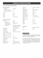 3
3
-
 4
4
-
 5
5
-
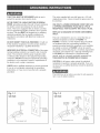 6
6
-
 7
7
-
 8
8
-
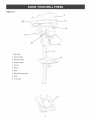 9
9
-
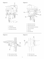 10
10
-
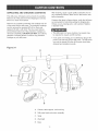 11
11
-
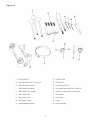 12
12
-
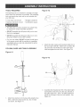 13
13
-
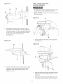 14
14
-
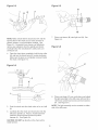 15
15
-
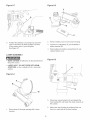 16
16
-
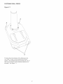 17
17
-
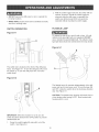 18
18
-
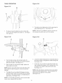 19
19
-
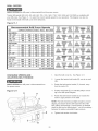 20
20
-
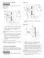 21
21
-
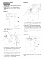 22
22
-
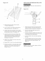 23
23
-
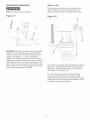 24
24
-
 25
25
-
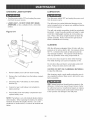 26
26
-
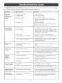 27
27
-
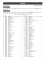 28
28
-
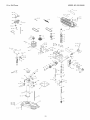 29
29
-
 30
30
-
 31
31
-
 32
32
-
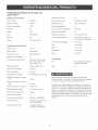 33
33
-
 34
34
-
 35
35
-
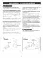 36
36
-
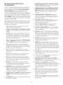 37
37
-
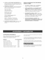 38
38
-
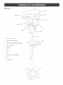 39
39
-
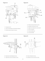 40
40
-
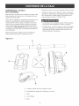 41
41
-
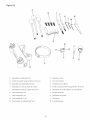 42
42
-
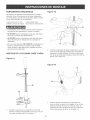 43
43
-
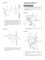 44
44
-
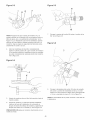 45
45
-
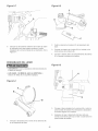 46
46
-
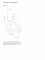 47
47
-
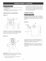 48
48
-
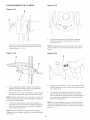 49
49
-
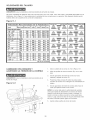 50
50
-
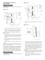 51
51
-
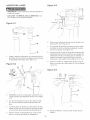 52
52
-
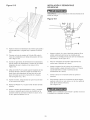 53
53
-
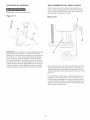 54
54
-
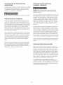 55
55
-
 56
56
-
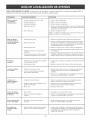 57
57
-
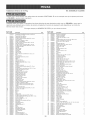 58
58
-
 59
59
-
 60
60


Craftsman 152229000 El manual del propietario
- Categoría
- Herramientas eléctricas
- Tipo
- El manual del propietario
en otros idiomas
- English: Craftsman 152229000 Owner's manual
Artículos relacionados
-
Craftsman 152.229020 El manual del propietario
-
-
-
-
-
-
-
Otros documentos
-
Delta DP300L TYPE 1 El manual del propietario
-
 MaxPro MPBDP16 Manual de usuario
-
-
-
-
-
NOVA of California 2110003A Instrucciones de operación
-
REED DM2100 Instrucciones de operación
-
REED 09304 Guía de instalación
-
