Craftsman 13953930DM El manual del propietario
- Categoría
- Abridor de puerta de garage
- Tipo
- El manual del propietario

Owner's IVlanuaVIVlanual Del Propietario
1/2 HP
31_N= GARAGE DOOR
ABRIDOR DE PUERTA DE
For Residential Use Only
iViodel • 139.53930DiVi
OPENER
COCHERA 31. MN=
m
Z
if-
m
m
Z_
{3
if-
Read and follow all safety rules
and operating instructions before
first use of this product.
Fasten the manual near the garage
door after installation.
Periodic checks of the opener are
required to ensure safe operation.
Leer y seguir todas las reglas de
seguridad y las instrucciones de
operacion antes de usar este
producto pot prirnera vez.
Guardar este manual cerca de la
puerta de la cochera.
Se deben realizar revisiones
periodicas del abridor de puertas
para asegurar su operacion
segura.
Sears, Roebuck and Co., Hoffman Estates, IL 60179 U.S.A
www.sears.com/craftsman

TABLE OF CONTENTS
Introduction 2- 7
Safety symbol and signal word review .............. 2
Preparing your garage door ...................... 3
Tools needed ................................. 3
Planning .................................. 4-5
Carton inventory ............................... 6
Hardware inventory ............................ 7
Assembly 8-11
Assemble the rail and install the trolley ............. 8
Fasten the rail to the motor unit ................... 9
Install the idler pulley ........................... 9
Install the chain/cable .......................... 10
Tighten the chain ............................. 11
Installation 11-26
Installation safety instructions ................... 11
Determine the header bracket location ............ 12
Install the header bracket ....................... 13
Attach the rail to the header bracket .............. 14
Position the opener ........................... 15
Hang the opener .............................. 16
Install the door control ......................... 17
Install the light ............................... 18
Attach the emergency release rope and handle ..... 18
Electrical requirements ......................... 19
Install The Protector System "R_................. 20-22
Fasten the door bracket ..................... 23-24
Connect the door arm to the trolley ............ 25-26
iNTRODUCTiON
Safety Symbol
and Signal Word Review
Adjustment 27-29
Adjust the travel limits ......................... 27
Adjust the force .............................. 28
Test the safety reversal system .................. 29
Test The Protector System "R_..................... 29
Operation 30-34
Operation safety instructions .................... 30
Using your garage door opener .................. 30
Using the wall-mounted Door Control ............. 31
To open the door manually ...................... 31
Care of your garage door opener ................. 32
Having a problem? ............................ 33
Diagnostic chart .............................. 34
Programming 35-36
To add or reprogram a hand-held remote control .... 35
To erase all codes ............................ 35
3-Function Remotes ........................... 35
To add, reprogram or change
a Keyless Entry PIN ........................... 36
Repair Parts 37-38
Rail assembly parts ........................... 37
Installation parts .............................. 37
Motor unit assembly parts ...................... 38
Accessories 39
Warranty 39
Repair Parts and Service Back cover
This garage door opener has been designed and tested to offer safe service provided it is installed, operated,
maintained and tested in strict accordance with the instructions and warnings contained in this manual.
Mechanical
Electrical
When you see these Safety Symbols and Signal Words on
the following pages, they will alert you to the possibility of
serious injury or death if you do not comply with the
warnings that accompany them. The hazard may come
from something mechanical or from electric shock. Read
the warnings carefully.
When you see this Signal Word on the following pages, it
will alert you to the possibility of damage to your garage
door and/or the garage door opener if you do not comply
with the cautionary statements that accompany it. Read
them carefully.

Preparing your garage door
Before you begin:
• Disable locks.
• Remove any ropes connected to garage door.
• Complete the following test to make sure your garage
door is balanced and is not sticking or binding:
1. Lift the door about halfway as shown. Release the
door. If balanced, it should stay in place, supported
entirely by its springs.
2. Raise and lower the door to see if there is any
binding or sticking.
If your door binds, sticks, or is out of balance, call a
trained door systems technician.
To prevent possible SERIOUSINJURYor DEATH:
• ALWAYScall a trained door systems technician if garage
door binds, sticks, or is out of balance.An unbalanced
garagedoor may NOTreversewhen required.
• NEVERtry to loosen, move or adjust garagedoor, door
springs, cables,pulleys, brackets or their hardware,ALL of
which are under EXTREMEtension.
• DisableALL locks and removeALL ropes connectedto
garagedoor BEFOREinstalling and operating garagedoor
opener to avoid entanglement.
To prevent damageto garage door and opener:
• ALWAYSdisable locks BEFOREinstalling and operatingthe
opener.
• ONLYoperategaragedoor opener at 120V, 60 Hzto avoid
malfunction and damage.
Sectional Door
One=Piece Door
Tools needed
During assembly, installation and adjustment of the
opener, instructions will call for hand tools as illustrated
below.
Stepladder
Level (optional)
Tape Measure
Drill
Drill Bits
3/16", 5/16"
and 5/32"
1/2", 5/8", 7/16", 9/16"
and 1/4"
Pencil
Wire Cutters
Pliers
HackSaw
Claw Hammer
Screwdriver
Adjustable End Wrench

Planning
Identify the type and height of your garage door. Survey
your garage area to see if any of the conditions below
apply to your installation. Additional materials may be
required. You may find it helpful to refer back to this page
and the accompanying illustrations as you proceed with
the installation of your opener.
Depending on your requirements, there are several
installation steps which may call for materials or hardware
not included in the carton.
• Installation Step 1 - Look at the wall or ceiling above
the garage door. The header bracket must be securely
fastened to structural supports.
• Installation Step 5 - Do you have a finished ceiling in
your garage? If so, a support bracket and additional
fastening hardware may be required.
• Installation Step 10 - Depending upon garage
construction, extension brackets or wood blocks may be
needed to install sensors.
• Installation Step 10 -Alternate floor mounting of the
safety reversing sensor will require hardware not
provided.
• Do you have an access door in addition to the garage
door? If not, Model 53702 Emergency Key Release is
required. See Accessories page.
Look at the garage door where it meets the floor. Any
gap between the floor and the bottom of the door must
not exceed 1/4" (6 mm). Otherwise, the safety reversal
system may not work properly. See Adjustment Step 3.
Floor or door should be repaired.
SECTIONAL DOOR INSTALLATIONS
• Do you have a steel, aluminum, fiberglass or glass panel
door? if so, horizontal and vertical
reinforcement is required (Installation Step 11).
• The opener should be installed above the center of the
door. If there is a torsion spring or center bearing plate
in the way of the header bracket, it may be installed
within 4 feet (1.22 m) to the left or right of the door
center. See Installation Steps 1 and 11.
• if your door is more than 7 feet (2.13 m) high, see rail
extension kits listed on Accessories page.
SECTIONAL DOOR INSTALLATION
Horizontal andvertical reinforcement
is neededfor lightweight garage doors
(fiberglass, steel, aluminum, door with
glass panels, etc.). See page 23 for details.
Header Wall
Safety Reversing Sensor
Gap between floor
and bottom of door
must not exceed 1/4" (6 mm).
Slack in chain tension
is normal when garage
door is closed.
Extension Spring
OR
Torsion Spring
Wall-mounted Access Door
Door Control
0
SafetyReversing
Sensor
FINISHEDCEILING
Support bracket &
fastening hardware
is required.
See page 16.
Motor unit

Planning (Continued)
ONE-PIECE DOOR INSTALLATIONS
• Generally, a one-piece door does not require
reinforcement, if your door is lightweight, refer to the
information relating to sectional doors in installation
Step 11.
• Depending on your door's construction, you may need
additional mounting hardware for the door bracket
(Step 11).
Without a properly working safety reversal system, persons
(particularly small children) could be SERIOUSLYINJUREDor
KILLEDby a closing garagedoor.
• Thegap betweenthe bottom of the garagedoor and the floor
MUST NOTexceed1/4" (6 mm). Otherwise,the safety
reversal system may NOTwork properly.
• Thefloor or the garage door MUSTbe repairedto eliminate
the gap.
ONE-PIECE DOOR WITHOUT TRACK
Safety Reversing Sensor
HeaderWall
Gapbetween floor
and bottom of door must
not exceed 1/4" (6 mm).
Rail
/
Access
Door
FINISHEDCEILING
Suppo_ bracket
& fastening
hardwareis required.
See page 16.
Slack in chain tension
is normal when garage
door is closed.
0
Safety Reversing
Sensor
Wall-mounted
Door Control
J
ONE-PIECE DOOR
SafetyReversing Sensor
,,,o,,....wa,,
Gap between floor and bottom of door must not /
exceed 1/4" (6 mm).
/
Motor Unit
CLOSEDPOSITION
RailTab
Cable
ight Curved
Door Door
Arm Arm
-- Garage Door
Trolley
Emergency
Release
Rope & Handle
CLOSEDPOSiTiON
Rail Tab
Bracdkert Rail
_D ooooooooooo)__/ LEmergency
t ..... ___, r ReleaseRope
oor Straight Door Curved I &-Ran-tile....
_//A Bracket Arm DoorArm I

Carton Inventory
Your garage door opener is packaged in one carton which
contains the motor unit and all parts illustrated below.
Accessories will depend on the model purchased, if
anything is missing, carefully check the packing material.
Hardware for assembly and installation is shown on the
next page. Save the carton and packing material until
installation and adjustment is complete.
Header Bracket Door Bracket
Safety Sensor
Bracket(2)
The Protector System_'_
(2) Safety Reversing Sensors
(1 Sending Eyeand 1 Receiving Eye)
with 2-Conductor White & White/Black
BellWire attached
2-Conductor Bell Wire
White & White/Red
Safety Labels
and
Literature
Straight Door
Arm Section

Hardware Inventory
Separate all hardware and group as shown below for the assembly and installationprocedures.
ASSEMBLY HARDWARE
Lock Nut Washer 5/8" Lock Washer 3/8" Nut 3/8"
1/4"-20
Bolt 1/4"-20x2-1/2
Trolley Threaded Shaft
Spacer(2)
J
Master
Link (2)
Idler Bolt
Carriage Bolt
1/4"-20xl/2" (2)
Wing Nut
1/4"-20 (2)
iNSTALLATiON HARDWARE
O
Ring
Fastener (3)
Nut 5/16"-18 (6) Handle
Lag Screw
5/16"-9xl -5/8" (4)
_g Screw
1/4"-14x5/8" (2)
Hex Bolt
5/16"-18x7/8" (4)
Screw
6ABxl" (2)
Drywall Anchors (2)
Clevis Pin Clevis Pin
5/16"xl -1/2" 5/16"xl"
Lock Washer 5/16" (5)
Insulated Staples
(Not shown)
Clevis Pin
5/16"x1-1/4"
Rope

ASSEMBLY STEP 1
Assemble the Rail & Install the Trolley
To avoid installation difficuJties, do not run the garage
door opener untiJ instructed to do so.
The front rail has a cut out "window" at the door end. The
front and back rail both have rail tabs. These rail tabs
MUST be on top of the rail when assembled.
1. Remove the straight door arm and hanging bracket
packaged inside the front rail and set aside for
Installation Step 5 and 12. NOTE: Toprevent INJURY
while unpacking the rail carefully remove the straight
door arm stored within the rail section.
2. Align the rail sections on a flat surface as shown and
slide the tapered ends into the larger ones. Tabs along
the side will lock into place.
3. Place the motor unit on packing material to protect the
cover, and rest the back end of the rail on top. For
convenience, put a support under the front end of the
rail.
To prevent INJURYfrom pinching, keephandsand fingers
away from the joints while assembling the rail.
4. As a temporary stop, insert a screwdriver into the hole
10" (25 cm) from the front end of the rail, as shown.
5. Check to be sure there are 4 plastic wear pads inside
the inner trolley. If they became loose during shipping,
check all packing material. Snap them back into position
as shown.
6. Slide the trolley assembly along the rail from the back
end to the screwdriver.
7. Slide the rail onto the "U" bracket, until it reaches all the
stops on the top and sides of the "U" bracket.
Back Rail Section
(TO MOTOR UNIT)
OuterTrolley,
Inner Tr011e
Wear Pads
SLIDE TO STOPS
ONTOPAND
SIDES OF
"U"BRACKET
FrontRail Section
(TO DOOR)
Rail
Tab
Trolley
Cut-0ut

ASSEMBLY STEP 2
Fasten the Rail to the Motor Unit
1. Insert a 1/4"-20x2-1/2 bolt, washer and spacer into the
cover protection bolt hole on the back end of the rail as
shown. Install lower spacer and washer then tighten
securely with a 1/4"-20 lock nut. DO NOT overtighten.
2. Remove the two bolts from the top of the motor unit.
3. Use the carton to support the front end of the rail.
4. Place the "U" bracket, flat side down onto the motor unit
and align the bracket hole with the bolt holes. Fasten
the "U" bracket with the previously removed bolts, hand
tighten ONLY and DO NOT use any power tools. The
use of power tools may permanently damage the
garage door opener.
5. Attach spreader to the motor unit with two screws.
HARDWARE SHOWN ACTUAL SiZE
O
Washer 5/8" Lock Nut 1/4"-20 Spacer
Bolt1/4"-20x2-1/2"
To avoid SERIOUSdamageto garagedoor opener, use ONLY
those bolts/fasteners mounted in the top of the opener.
B01t
1/4"-20x2-1/2"
\
Washer 5/8" l
Spacer
Cover
Protection
Bolt Hole
B01t
I
I
"U" Bracket
Chain
Spreader
Washer 5/8" "_"
Lock Nut "/_
1/4"-20
ASSEMBLY STEP 3
Install the Idler PuUey
1. Lay the chain/cable beside the rail, as shown. Grasp the
end of the cable and pass approximately 12" (30 cm) of
cable through the window. Allow it to hang until
Assembly Step 4.
2. Remove the tape from the idler pulley. The inside center
should be pre-greased. If dry, regrease to ensure proper
operation.
3. Place the idler pulley into the window as shown.
4. Insert the idler bolt from the top through the rail and
pulley. Tighten with a 3/8" lock washer and nut
underneath the rail until the lock washer is compressed.
5. Rotate the pulley to be sure it spins freely.
6. Locate the rail tab. The rail tab is between the idler
bolt and the trolley in the front rail section. Use a flat
head screwdriver and lift the rail tab until the tab is
vertical (90°).
Chain and
Cable
._ Grease
- - -.._lnside Pulley
Lock i _ Idler
Washer _ Pulley
3/8" i
_-- Nut 3/8"
Cable Link
CORRECT
Q
iNCORRECT
Q
HARDWARE SHOWN ACTUAL SiZE
_ IdlerBolt Nut3/8"
Lock Washer 3/8"

ASSEMBLY ST P 4
Install the Chain/Cable
1. Pull the cable around the idler pulley and toward the
trolley.
2. Connect the cable to the retaining slot on the trolley, as
shown (Figure 1):
• From below, push pins of master link bar up through
cable link and trolley slot.
• Push master link cap over pins and past pin notches.
• Slide clip-on spring over cap and onto pin notches
until both pins are securely locked in place.
3. With the trolley against the screwdriver, dispense the
remainder of the cable/chain along the rail toward the
motor unit into the slot on the chain spreader, around
the sprocket onto the chain spreader and continuing to
the trolley assembly. The sprocket teeth must engage
the chain (Figure 2).
4. Check to make sure the chain is not twisted, then
connect it to the threaded shaft with the remaining
master link.
5. Thread the inner nut and lock washer onto the trolley
threaded shaft (Figure 3).
6. Insert the trolley threaded shaft through the hole in the
trolley. Be sure the chain is not twisted (Figure 3).
7. Loosely thread the outer nut onto the trolley
threaded shaft.
8. Remove the screwdriver.
Figure 1
To avoid possible SERIOUSINJURYto fingers from moving
garagedoor opener:
• ALWAYSkeephand clearof sprocket while operating
opener.
• Securely attachchain spreader BEFOREoperating.
Dispensing Carton
LeaveChain and Cable
Inside Dispensing
Carton to Prevent Kinking.
Figure 2
KeepChain and Cable
Taut When Dispensing
Sprocket
Figure 3
Outer Nut
Master
Inner Nut
Lock Washer,
Front Rail
Section
(TO DOOR)
Threaded
Shaft
Master Link
10

ASSEMBLY STEP 5
Tighten the Chain
1. Spin the inner nut and lock washer down the trolley
threaded shaft, away from the trolley.
2. To tighten the chain, turn outer nut in the direction
shown (Figure 1).
3. When the chain is approximately 1/4" (6 mm) above the
base of the rail at its midpoint, re-tighten the inner nut to
secure the adjustment (Figure 2).
Sprocket noise can result if chain is too loose.
When installation is complete, you may notice some chain
droop with the door closed. This is normal. If the chain
returns to the position shown in Figure 2 when the door is
open, do not re-adjust the chain.
NOTE: During future maintenance, ALWAYS pull the
emergency release handle to disconnect trolley before
adjusting chain. You may notice loosening of chain after
Adjustment Step 3 (Test the Safety Reversal System).
Check for proper tension and readjust chain ff necessary.
Then repeat Adjustment Step 3.
You have now finished assembling your garage door
opener. Please read the following warnings before
proceeding to the installation section.
Figure 1
Figure 2
Trolley
Outer Lock Threaded
Nut Washer Shaft
To Tighten Outer Nut
Inner Nut
To Tighten
Inner Nut
Chain
Rail
1/4" (6 ram)
Mid length of Rail
INSTALLATION
Toreducethe risk ofSEVEREINJURYor DEATH:
1. READAND FOLLOWALL INSTALLATIONWARNINGSAND
INSTRUCTIONS.
2. Installgarage door opener ONLYon properly balancedand
lubricated garage door. An improperly balanceddoor may
NOTreversewhen required and could result in SEVERE
INJURYor DEATH.
3. ALL repairsto cables,spring assembliesand other hardware
MUSTbe madeby a trained door systemstechnician BEFORE
installing opener.
4. DisableALL locks and removeALL ropesconnectedto garage
door BEFOREinstalling openerto avoidentanglement.
5. install garage door opener7 feet (2.13 m) or moreabove
floor.
6. Mount the emergencyreleasewithin reach,but at least 6 feet
(1.8 m) abovethefloor and avoiding contact with vehiclesto
avoid accidentalrelease.
7. NEVERconnect garagedoor openerto power source until
instructed to do so.
8. NEVERwear watches, rings or looseclothing while installing
or servicing opener.They could be caught in garagedoor or
opener mechanisms.
9. install wall-mounted garagedoor control:
• within sight of the garage door.
• out of reachof children at minimum height of 5 feet
(1.5 m).
• awayfrom ALL moving parts of thedoor.
10. Placeentrapmentwarning labelon wall next to garage door
control.
11. Placemanual release/safetyreversetest label in plain view
on inside of garagedoor.
12. Uponcompletion of installation, test safety reversalsystem.
Door MUSTreverseon contact with a 1-1/2" (3.8 cm) high
object (or a 2x4 laid flat) on the floor.
11

iNSTALLATiON STEP 1
Determine the Header Bracket Location
To prevent possible SERIOUSINJURYor DEATH:
• HeaderbracketMUST be RIGIDLYfastened to structural
support on headerwall or ceiling, otherwise garagedoor
might NOTreversewhen required. DONOTinstall header
bracket overdrywall.
• Concreteanchors MUSTbe usedif mounting headerbracket
or 2x4 into masonry.
• NEVERtry to loosen, move or adjust garagedoor, springs,
cables,pulleys, brackets, or their hardware,ALL of which
are under EXTREMEtension.
• ALWAYScall a trained door systems technician if garage
door binds, sticks, or is out of balance.An unbalanced
garagedoor might NOTreversewhen required.
Installation procedures vary according to garage door
types. Follow the instructions which apply to your door.
1. Close the door and mark the inside vertical centerline of
the garage door.
2. Extend the line onto the header wall above the door.
You can fasten the header bracket within 4 feet
(1.22 m) of the left or right of the door center only if
a torsion spring or center bearing plate is in the
way; or you can attach it to the ceiling (see page 13)
when clearance is minimal. (it may be mounted on
the wall upside down if necessary, to gain
approximately 1/2" (1 cm).
If you need to install the header bracket on a 2x4
(on wall or ceiling), use lag screws (not provided)
to securely fasten the 2x4 to structural supports as
shown here and on page 13.
3. Open your door to the highest point of travel as shown.
Draw an intersecting horizontal line on the header wall
above the high point:
• 2" (5 cm) above the high point for sectional door and
one-piece door with track.
• 8" (20 cm) above the high point for one-piece door
without track.
This height will provide travel clearance for the top edge
of the door.
NOTE: If the total number of inches exceeds the height
available in your garage, use the maximum height
possible, or refer to page 13 for ceiling installation.
HeaderWall
)
ql[
Header Wall
ack
Highest Point
of Travel
--Door
Sectional door with cnrvedtrack
Wall
Door 2° ihest
I _ Point
_Hardware i of Travel
One-piece deer without track:
jamb hardware
Un.f!nished
Ceiling _ BRACKETHEADERFORNOuNTCEiLINGOPTIONAL
Vertical Centerline
of GarageDoor
2x4 Structural
Supports
HeaderWall Track
// Highest Point
of Travel
f
One-piece door with horizontal track
Door
Header Wall
',- 8" (20 cm)
--::==-=_,
,s _ Highest
Point
of Travel
Pivot
One-piece door withont track:
pivothardware
12

iNSTALLATiON STEP 2
Install the Header Bracket
You can attach the header bracket either to the wall above
the garage door, or to the ceiling. Follow the instructions
which will work best for your particular requirements. Do
not install the header bracket over drywall. If installing
into masonry, use concrete anchors (not provided).
WALL HEADER BRACKET INSTALLATION
• Center the bracket on the vertical centerline with the
bottom edge of the bracket on the horizontal line as
shown (with the arrow pointing toward the ceiling).
• Mark the vertical set of bracket holes. Drill 3/16" pilot
holes and fasten the bracket securely to a structural
support with the hardware provided.
HARDWARE SHOWN ACTUAL SIZE
LagScrew
5/16"-9xl-5/8"
Wall Mount
Optional
Mounting Holes
- Header Wall
2x4
Structural
Support
/
1
Horizontal
Line
HighestPoint of
GarageDoorTravel
Vertical
Centerline
of Garage Door
_ Lag Screws
5/16"-9xl-5/8"
Door Spring
Vertical
Centerline
of GarageDoor
CEILING HEADER BRACKET INSTALLATION
• Extend the vertical centerline onto the ceiling as shown.
• Center the bracket on the vertical mark, no more than
6" (15 cm) from the wall. Make sure the arrow is
pointing away from the wall. The bracket can be
mounted flush against the ceiling when clearance
is minimal.
• Mark the side holes. Drill 3/16" pilot holes and fasten
bracket securely to a structural support with the
hardware provided.
Ceiling Mounting Holes
Bracket _j
6"(15cm) Max_lmum
Door
Spring
- Finished Ceiling -
Vertical Centerline
of GarageDoor
- Header Wall -
Centefline
of Garage Door
13

iNSTALLATiON STEP 3
Attach the Rail to the Header Bracket
• Position the opener on the garage floor below the
header bracket. Use packing material as a protective
base. NOTE: If the door spring is in the way you'll need
help. Have someone hold the opener securely on a
temporary support to allow the rail to clear the spring.
• Position the rail bracket against the header bracket.
• Align the bracket holes and join with a clevis pin
5/16"xl -1/2" as shown.
• Insert a ring fastener to secure.
Header Wall
Header Bracket
Idler Pulley
Header 0
Bracket
Mounting
Hole
Door
Temporary
Support
HARDWARE SHOWN ACTUAL SiZE
ol ©
ClevisPin5/]B"xl-]/2" RingFastener
14

iNSTALLATiON STEP 4
Position the Opener
Follow instructions which apply to your door type as
illustrated.
SECTIONAL DOOR OR ONE-PIECE DOOR WITH
TRACK
A 2x4 laid flat is convenient for setting an ideal
door-to-rail distance.
• Raise the opener onto a stepladder. You will need help
at this point if the ladder is not tall enough.
• Open the door all the way and place a 2x4 laid flat on
the top section beneath the rail.
• If the top section or panel hits the trolley when you raise
the door, pull down on the trolley release arm to
disconnect inner and outer sections. Slide the outer
trolley toward the motor unit. The trolley can remain
disconnected until Installation Step 12 is completed.
To prevent damageto garage door, rest garagedoor opener
rail on 2x4 placedon top section of door.
Rail
Door
2x4 is used to determine
the correct mounting height
from ceiling.
__olley
leaseArm --t J
ENGAGED RELEASED _9/
ONE-PIECE DOOR WITHOUT TRACK
A 2x4 on its side is convenient for setting an ideal
door-to-rail distance.
• Raise the opener onto a stepladder. You will need help
at this point if the ladder is not tall enough.
• Open the door all the way and place a 2x4 on its side
on the top section of the door beneath the rail.
• The top of the door should be level with the top of the
motor unit. Do not position the opener more than
4" (10 cm) above this point.
Header
i
Top of Door
2x4 is used to determine
the correct mounting height
from ceiling.
15

iNSTALLATiON STEP 5
Hang the Opener
Three representative installations are shown. Yours may
be different. Hanging brackets should be angled (Figure 1)
to provide rigid support. On finished ceilings (Figure 2 and
Figure 3), attach a sturdy metal bracket to structural
supports before installing the opener. This bracket and
fastening hardware are not provided.
1. Measure the distance from each side of the motor unit
to the structural support.
2. Cut both pieces of the hanging bracket to required
lengths.
3. Drill 3/16" pilot holes in the structural supports.
4. Attach one end of each bracket to a support with
5/16"-9xl-5/8" lag screws.
5. Fasten the opener to the hanging brackets with
5/16"-18x7/8" hex bolts, lock washers and nuts.
6. Check to make sure the rail is centered over the door
(or in line with the header bracket if the bracket is not
centered above the door).
7. Remove the 2x4. Operate the door manually. If the door
hits the rail, raise the header bracket.
NOTE: DO NOT connect power to opener at this time.
HARDWARE SHOWN ACTUAL SIZE
LagScrew5/16"-9xl-5/8"
HexBolt
5/16"-18x7/8" Nut5/16"-18 LockWasher5/16"
To avoid possible SERIOUSINJURYfrom a falling garagedoor
opener,fasten it SECURELYto structural supports of the
garage.Concreteanchors MUSTbe usedif installing any
brackets into masonry.
Figure 1
Structural
Supports
LagScrew
5/16"-9xl-5/8"
Bolt 5/16"-18x7/8"
Lock Washer 5/16"
Nut 5/16"-18
Figure 2
Measure
l__
, Distance
Provided)
Bolt 5/16"-18x7/8"
--- Lock Washer 5/16"
Nut 5/16"-18
Bolt 5/16"-18x7/8"
Lock Washer 5/16"
Nut 5/16"-18
Figure 3
Lag Screw
5/16"-9xl-5/8"
(Not Provided)
Bolt 5/16"-18x7/8"
Lock Washer 5/16"
Nut 5/16"-18
Bolt 5/16"-18x7/8"
Lock Washer 5/16"
'16"-18
16

iNSTALLATiON STEP 6
Irestall the Door Control
Locate door control within sight of door, at a minimum
height of 5 feet (1.5 m) where small children cannot reach,
away from moving parts of door and door hardware.
If installing into drywall, drill 5/32" holes and use the
anchors provided. For pre-wired installations (as in new
home construction), it may be mounted to a single gang
box (Figure 1).
1. Strip 7/16" (11 mm) of insulation from one end of bell
wire and connect to the two screw terminals on back of
door control by color: white wire to 2 and white/red wire
to the 1 (Figure 2).
2. Remove cover by gently prying along one side with a
screwdriver (Figure 3). Fasten with 6ABxl"
self-tapping screws (drywall installation) or 6-32x1"
machine screws (into gang box) as follows:
• Install bottom screw, allowing 1/8" (3 mm) to protrude
above wall surface.
• Position bottom of door control on screw head and
slide down to secure. Adjust screw for snug fit.
• Drill and install top screw with care to avoid cracking
plastic housing. DO NOT overtighten,
• Insert top tabs and snap on cover.
3. (For standard installation only) Run bell wire up wall
and across ceiling to motor unit. Use insulated staples to
secure wire in several places. DO NOT pierce wire with
a staple, creating a short or open circuit.
4. Strip 7/16" (11 mm) of insulation from end of bell wire.
Connect bell wire to the quick-connect terminals as
follows: white to white and white/red to red (Figure 4).
NOTE: When connecting multiple door controls to the
opener, twist same color wires together. Insert wires into
quick-connect holes: white to white and red/white to red.
5. Position the antenna wire as shown.
6. Use tacks or staples to permanently attach entrapment
warning label to wall near door control, and manual
release/safety reverse test label in a prominent location
on inside of garage door.
NOTE: DO NOT connect power and operate opener at
this time, The trolley will travel to the full open position but
will not return to the close position until the sensor beam is
connected and properly aligned,
To prevent possible SERIOUSINJURYor DEATHfrom
electrocution:
• Besure power is NOTconnected BEFOREinstalling door
control.
• ConnectONLYto 24 VOLTlow voltage wires.
To prevent possible SERIOUSINJURYor DEATHfrom a closing
garagedoor:
• Install door control within sight of garage door, out of reach
of children ata minimum height of 5 feet (1.5 m), and away
from ALL moving parts of door.
• NEVERpermit children to operate or playwith door control
push buttons or remote control transmitters.
• Activate door ONLYwhen it can be seenclearly, is properly
adjusted,and there are no obstructions to door travel.
• ALWAYSkeepgarage door in sight until completely closed.
NEVERpermit anyoneto cross pathof closing garage door.
HARDWARE SHOWN ACTUAL SIZE
Screw 6ABxl"
Control Console (std installation)
Screw 6-32xl"
Control Console (pre-wired)
Insulated Staples
(Not shown)
Drywall Anchors
Figure 1
PRE-WlRED
INSTALLATION
24 Volt
2-Conductor
Bell Wire
Figure 2
(BACK VIEW)
weirl_ T°p
Mounting
Hole
Terminal
Screws
Bottom
Bell Mounting
Hole
Figure 3
REMOVE&
REPLACECOVER
To Replace,
Insert Top Tabs
First
To Remove,
Twist Here
r:_rlgure 4 DoorControl
Connections
I
To release or insert wire, I
push in tab with screwdriver tip
I
Strip wire 7/16" (11 mm) J
I _7/16" (11 ram) ]_.
Red White Grey
STANDARD
CONTROLCONSOLE
-- 2-Conductor
Bell Wire
Lighted
Push Button
17

iNSTALLATiON STEP 7
Install the Light
• Press the release tabs on both sides of lens. Gently
rotate lens back and downward until the lens hinge is in
the fully open position. Do not remove the lens.
• Install up to a 100 watt maximum light bulb in the socket.
The light will turn ON and remain lit for approximately
4-1/2 minutes when power is connected. Then the light
will turn OFF.
• Reverse the procedure to close the lens.
• Use A19, standard neck garage door opener bulbs for
replacement.
NOTE: Use only a standard light bulb. The use of short
neck or speciality light bulb may overheat the endpanel or
light socket.
To prevent possible OVERHEATINGof the endpanelor light
socket,
• DONOTuseshort neck or specialty light bulbs.
• DONOTuse halogenbulbs. Use ONLYincandescent.
To prevent damageto the opener:
• DONOTuse bulbs larger than IOOW.
• ONLYuseA19 size bulbs.
100 Watt (Max)
_ tandard Light Bulb
Release Tab
\
\
iNSTALLATiON STEP 8
Attach the Emergency Release Rope
and Handle
1. Insert one end of the emergency release rope through
the handle. Make sure that "NOTICE" is right side up.
Tie a knot at least 1 inch (2.5 cm) from the end of the
emergency release rope.
2. Insert the other end of the emergency release rope
through the hole in the trolley release arm. Mount the
emergency release within reach, but at least 6 feet
(1.83 m) above the floor, avoiding contact with vehicles
to prevent accidental release and secure with a knot.
NOTE: If it is necessary to cut the emergency release
rope, seal the cut end with a match or lighter to prevent
unraveling. Ensure the emergency release rope and
handle are above the top of aft vehicles to avoid
To prevent possible SERIOUSINJURYor DEATHfrom a falling
garagedoor:
• If possible,use emergency releasehandleto disengage
trolley ONLYwhen garagedoor is CLOSED.Weak or broken
springs or unbalanceddoor could result in an open door
falling rapidly and/or unexpectedly.
• NEVERuseemergency releasehandle unless garage
doorway is clear of persons and obstructions.
• NEVERusehandle to pull door open or closed. If rope knot
becomes untied, you could fall.
Trolley
- I
_ Overhand
Emergency
Knot
ReleaseHandle
18

iNSTALLATiON STEP 9
Electrical Requirements
To avoid installation difficulties, do not run the opener
at this time.
To reduce the risk of electric shock, your garage door
opener has a grounding type plug with a third grounding
pin. This plug will only fit into a grounding type outlet. If
the plug doesn't fit into the outlet you have, contact a
qualified electrician to install the proper outlet.
To prevent possible SERIOUSINJURYor DEATHfrom
electrocution or fire:
• Besure power isNOTconnectedto the opener,and
disconnect powerto circuit BEFOREremoving cover to
establish permanentwiring connection.
• Garagedoor installationand wiring MUSTbe in compliance
with ALL local electrical and building codes.
• NEVERusean extension cord, 2-wire adapter,or change
plug in anyway to makeit fit outlet. Besurethe opener is
grounded.
if permanent wiring is required by your local code,
refer to the following procedure.
To make a permanent connection through the 7/8" hole in
the top of the motor unit:
• Remove the motor unit cover screws and set the cover
aside.
• Remove the attached 3-prong cord.
• Connect the black (line) wire to the screw on the brass
terminal; the white (neutral) wire to the screw on the
silver terminal; and the ground wire to the green ground
screw. The opener must be grounded.
• Reinstall the cover.
To avoid installation difficulties, do not run the opener
at this time.
GroundTab
Green
GroundScrew
Ground
WhiteWire BlackWire
19

iNSTALLATiON STEP 10
Install The Protector System ®
The safety reversing sensor must be connected and
aligned correctly before the garage door opener will
move in the down direction.
iMPORTANT iNFORMATiON ABOUT THE SAFETY
REVERSING SENSOR
When properly connected and aligned, the sensor will
detect an obstacle in the path of its electronic beam. The
sending eye (with an amber indicator light) transmits an
invisible light beam to the receiving eye (with a green
indicator light). If an obstruction breaks the light beam
while the door is closing, the door will stop and reverse to
full open position, and the opener lights will flash 10 times.
The units must be installed inside the garage so that the
sending and receiving eyes face each other across the
door, no more than 6" (15 cm) above the floor. Either can
be installed on the left or right of the door as long as the
sun never shines directly into the receiving eye lens.
The mounting brackets are designed to clip onto the track
of sectional garage doors without additional hardware.
Be sure power is NOTconnectedto the garagedoor opener
BEFOREinstalling the safety reversing sensor.
To prevent SERIOUSINJURYor DEATHfrom a closing
garagedoor:
• Correctly connect and align the safety reversingsensor. This
required safety deviceMUST NOTbe disabled.
• install the safety reversing sensor so beamis NOHIGHER
than 6"(15 cm) above garagefloor.
If it is necessary to mount the units on the wall, the
brackets must be securely fastened to a solid surface such
as the wall framing. Extension brackets (see accessories)
are available if needed. If installing in masonry
construction, add a piece of wood at each location to
avoid drilling extra holes in masonry if repositioning is
necessary.
The invisible light beam path must be unobstructed. No
part of the garage door (or door tracks, springs, hinges,
rollers or other hardware) may interrupt the beam while
the door is closing.
D € - 0
_7 _- - "_- -
|,[ 1I l ll
SafetyReversingSensor InvisibleLight SafetyReversing
ProtectionArea
Facing the door from inside the garage
20

iNSTALLiNG THE BRACKETS
Be sure power to the opener is disconnected. Install
and align the brackets so the sensors will face each other
across the garage door, with the beam no higher than
6" (15 cm) above the floor. They may be installed in one of
three ways, as follows.
Garage door track installation (preferred):
• Slip the curved arms over the rounded edge of each
door track, with the curved arms facing the door. Snap
into place against the side of the track, it should lie
flush, with the lip hugging the back edge of the track, as
shown in Figure 1.
if your door track will not support the bracket securely, wall
installation is recommended.
Wall installation (Figures 2 & 3):
• Place the bracket against the wall with curved arms
facing the door. Be sure there is enough clearance for
the sensor beam to be unobstructed.
• if additional depth is needed, an extension bracket (See
Accessories) or wood blocks can be used.
• Use bracket mounting holes as a template to locate and
drill (2) 3/16" diameter pilot holes on the wall at each
side of the door, no higher than 6" (15 cm) above the
floor.
• Attach brackets to wall with lag screws (Not provided).
• If using extension brackets or wood blocks, adjust right
and left assemblies to the same distance out from the
mounting surface. Make sure all door hardware
obstructions are cleared.
Floor installation (Figure 4):
• Use wood blocks or extension brackets (See
Accessories) to elevate sensor brackets so the lenses
will be no higher than 6" (15 cm) above the floor.
• Carefully measure and place right and left assemblies at
the same distance out from the wall. Be sure all door
hardware obstructions are cleared.
• Fasten to the floor with concrete anchors as shown.
Figure 1 DOORTRACKMOUNT (RIGHT SIDE)
Track
\
Lip
Safety
Reversing'_
Sensor
Bracket
Figure 2 WALL MOUNT (RIGHT SIDE)
Indicator
Light
FastenWoodBlocktoWallwith
IScrews(Notprovided)
Indicator
Light Safety
Reversing
Sensor
Bracket
Figure 3
(Providedwith
ExtensionBracket)---_"
WALLMOUNT(RIGHTSIDE)
ii_ Extension Bracket
See Accessories)
I I.,,n (Providedwith
'_--_ .,,"_._1 Extension Bracket)
_" _ L"-J3',J'_ -'_'_ Reversing
\ Sensor
I " Bracket
Lens Indicator
Light
Figure 4 FLOORMOUNT (RIGHT SIDE)
Carriage Bolt
1/4"-20xl/2"
HARDWARE SHOWN ACTUAL SIZE
Staples(Notshown)
Wing Nut
1/4"-20
J
-- ttach with
Concrete Anchors
; (Not provided)
Indicator
Light
Safe_
Reversing
Sensor
Bracket
21

MOUNTING AND WiRiNG THE SAFETY REVERSING
SENSORS
• Slide a 1/4"-20xl/2" carriage bolt head into the slot on
each sensor. Use wing nuts to fasten sensors to
brackets, with lenses pointing toward each other across
the door. Be sure the lens is not obstructed by a bracket
extension (Figure 5).
• Finger tighten the wing nuts.
• Run the wires from both sensors to the opener. Use
insulated staples to secure wire to wall and ceiling.
• Strip 7/16" (11 mm) of insulation from each set of wires.
Separate white and white/black wires sufficiently to
connect to the opener quick-connect terminals. Twist
like colored wires together, insert wires into quick-
connect holes: white to white and white/black to grey
(Figure 6).
ALiGNiNG THE SAFETY REVERSING SENSORS
• Plug in the opener. The indicator lights in both the
sending and receiving eyes will glow steadily if wiring
connections and alignment are correct.
The sending eye amber indicator light will glow regardless
of alignment or obstruction. If the green indicator light in
the receiving eye is off, dim, or flickering (and the invisible
light beam path is not obstructed), alignment is required.
• Loosen the sending eye wing nut and readjust, aiming
directly at the receiving eye. Lock in place.
• Loosen the receiving eye wing nut and adjust sensor
until it receives the sender's beam. When the green
indicator light glows steadily, tighten the wing nut.
Figure 5
Carriage Bolt
1/4"-20xl/2"
_ Wing Nut
0"-
TROUBLESHOOTING THE SAFETY REVERSING
SENSORS
1. If the sending eye indicator light does not glow steadily
after installation, check for:
• Electric power to the opener.
• A short in the white or white/black wires. These can
occur at staples, or at opener connections.
• incorrect wiring between sensors and opener.
• A broken wire.
2. If the sending eye indicator light glows steadily but the
receiving eye indicator light doesn't:
• Check alignment.
• Check for an open wire to the receiving eye.
3. If the receiving eye indicator light is dim, realign
either sensor.
NOTE: When the invisible beam path is obstructed or
misaligned while the door is closing, the door will reverse.
If the door is already open, it will not close. The opener
lights will blink 10 times. See page 20.
Figure 6
Bell Wire __ Finished __
Ceiling
Connect Wire to
Quick-Connect Terminals
Bell Wire
i
1. Strip wire 7/16"
(11 mm)
Safety Reversing Sensor
Invisible Light Beam
Protection Area
Safety Reversing Sensor
22
2. Twist like colored
wires together
3. To release or insert
wire, push in tab with
screwdriver tip
Red White Grey
Quick-Connect Terminals

iNSTALLATiON STI:P 1 1
Fasten the Door Bracket
Follow instructions which apply to your door type
as illustrated below or on the following page.
A horizontal reinforcement brace should be long
enough to be secured to two or three vertical
supports. A vertical reinforcement brace should cover
the height of the top panel.
Figure 1 shows one piece of angle iron as the horizontal
brace. For the vertical brace, 2 pieces of angle iron are
used to create a U-shaped support. The best solution is to
check with your garage door manufacturer for an opener
installation door reinforcement kit.
NOTE: Many door reinforcement kits provide for direct
attachment of the clevis pin and door arm. In this case you
will not need the door bracket; proceed to Step 12.
SECTIONAL DOORS
1. Center the door bracket on the previously marked
vertical centerline used for the header bracket
installation. Note correct UP placement, as stamped
inside the bracket.
2. Position the top edge of the bracket 2"-4" (5-10 cm)
below the top edge of the door, OR directly below any
structural support across the top of the door.
3. Mark, drill holes and install as follows, depending on
your door's construction:
Metal or light weight doors using a vertical angle iron
brace between the door panel support and the door
bracket:
• Drill 3/16" fastening holes. Secure the door bracket
using the two 1,/4"-14x5/8" self-threading screws
(Figure 2A).
• Alternately, use two 5/16" bolts, lock washers and nuts
(not provided) (Figure 2B).
Metal, insulated or light weight factory reinforced
doors:
• Drill 3/16" fastening holes. Secure the door bracket
using the self-threading screws (Figure 3).
Wood Doors:
• Use top and bottom or side to side door bracket holes.
Drill 5/16" holes through the door and secure bracket
with 5/16"x2" carriage bolts, lock washers and nuts (not
provided) (Figure 4).
NOTE: The 1/4"-14x5/8" self-threading screws are not
intended for use on wood doors.
HARDWARE SHOWN
ACTUAL SIZE
Self-Threading
Screw
1/4"-14x5/8"
Fiberglass, aluminum or lightweight steel garagedoors WILL
REQUIREreinforcement BEFOREinstallation of door bracket.
Contact your door manufacturer for reinforcement kit.
Figure 1
Door
Bracket
Location
Vertical
Centerline --
of Garage
Door
HORIZONTALAND VERTICAL
REINFORCEMENTIS NEEDEDFOR
LIGHTWEIGHTGARAGEDOORS
(FIBERGLASS, ALUMINUM, STEEL,
DOORSWITH GLASSPANEL,ETC.).
(NOT PROVIDED)
!t! !II!1
Vertical
orcement
Io}_l_.l vertical centerline of
iollOlilGarale Door
Door Bracket _.. _'
Self-Threading
Screw1/4"-14x5/8"
Figure 2A
(Not Provided)
Vertical Centerline of
-'_ _.!_t GarageDoor
" i
. UP
Door Bracket @_._,
LockWasher5/16" _'-
Nut 5/16"-18
Figure 2B
_rtical
- Centerline
of Garage Door
UP
Screw
1/4"-14x5/8"
Figure 3
Inside Edge
of Door or
Reinforcement Board
Bolt 5/16"x2"/_.
(Not Provided)<_
• UP
Vertical _.._"-
Centerline _; ,,_,_
of Garage _ ,€_,._.
Door
Figure 4
23

ONE-PIECEDOORS
Pleasereadandcomplywiththewarningsand
reinforcementinstructionsonthepreviouspage.They
applytoone-piecedoorsalso.
• Centerthedoorbracketonthetopofthedoor,inline
withtheheaderbracketasshown.Markeithertheleft
andright,orthetopandbottomholes.
• Metal Doors: Drill 3/16" pilot holes and fasten the
bracket with the 1,/4"-14x5/8" self-threading screws
provided.
• Wood Doors: Drill 5/16" holes and use 5/16"x2"
carriage bolts, lock washers and nuts (not provided) or
5/16"x1-1/2" lag screws (not provided) depending on
your installation needs.
HARDWARE SHOWN
ACTUAL SIZE
Self-ThreadingScrew
1/4"-14x5/8"
NOTE: The door bracket may be installed on the top
edge of the door if required for your installation. (Refer to
the dotted line optional placement drawing.)
Header Wall
2x4 Support
Door
Bracket
Optional
Placement
of Door
Bracket
Vertical
Centerline of
Garage Door
HORIZONTALAND VERTICAL
REINFORCEMENTIS NEEDED
FOR LiGHTWEiGHTGARAGE
DOORS(FIBERGLASS, ALUMINUM,
STEEL, DOORSWITH GLASS
PANEL,ETC.). (NOT PROVIDED)
Fora door with no exposed framing,
or for the optional installation, use
lagscrews 5/16"x1-1/2" (Not Provided)
to fasten door bracket.
Door
Bracket
__ elf-Threading
Screw
' 1/4"-14x5/8"
Top of Door
(Inside Garage)
Optional
Placement
METAL DOOR
Nut _ Lock
5/16"-18 --_ @)---- Washer
, 5/16"
Top of Door
Garage)
Top Edge
of Door
Optional
Placement
, & Carriage Bolt
5/16"x2"
(Not Provided)
WOOD DOOR
24

iNSTALLATiON STEP 12
Connect Door Arm to Trolley
Follow instructions which apply to your door type as
illustrated below and on the following page.
SECTIONAL DOORS ONLY
• Make sure garage door is fully closed. Pull the
emergency release handle to disconnect the outer trolley
from the inner trolley. Slide the outer trolley back (away
from the pulley) about 8" (20 cm) as shown in Figures 1,
2 and 3.
• Figure 1:
- Fasten straight door arm section to outer trolley with
the 5/16"x1" clevis pin. Secure the connection with a
ring fastener.
- Fasten curved section to the door bracket in the same
way, using the 5/16"x1-1/4" clevis pin.
IMPORTANT: The groove on the straight door arm
MUST face away from the curved door arm (Figure 4),
• Figure 2:
- Bring arm sections together. Find two pairs of holes
that line up and join sections. Select holes as far apart
as possible to increase door arm rigidity.
• Figure 3, Hole alignment alternative:
- if holes in curved arm are above holes in straight arm,
disconnect straight arm. Cut about 6" (15 cm) from the
solid end. Reconnect to trolley with cut end down as
shown.
- Bring arm sections together.
- Find two pairs of holes that line up and join with bolts,
lock washers and nuts.
• Pull the emergency release handle toward the opener at
a 45° angle so that the trolley release arm is horizontal.
Proceed to Adjustment Step 1, page 27. Trolley will
re-engage automatically when opener is operated.
HARDWARE SHOWN ACTUAL SIZE
©
LockWasher 5/1B" RingFastener
Clevis Pin Clevis Pin
5/16"x1" (Trolley) 5/16"x1-1/4" (Door Bracket)
Nut 5/16"-18
Hex Bolt
5/16"-18x7/8"
Figure 1
Figure 2
Figure 3
Figure 4
25
Pulley
,,
8" (20 cm) rain. _.},,
Ring
Fastener
DOor
ClevisPin
5/16"x1-1/4"
Curved
Door Arm
Outer
Trolley
ClevisPin
5/16"x1"
Emergency
Handle
ht
DoorArm
Pulley
\i- 8"(2Ocm) min. i
Lock /
Washers /o_
Nuts 5/16" /o/
Nuts \ /o/
5,1618-t /°°/
Bracket
_ Bolts
5/16"-18x7/8"
Pulley
i÷ 8 (2o°m)mi°.÷::
Nuts 5/16 /o7
5/16-1s t /o/
I
" o(9/ " Cut this end
CORRECT
Cur
Do(
/
j,
)
INCORRECT
Ct
D,
AI
/

ALL ONE-PIECE DOORS
1.Assemble the door arm, Figure 5:
IMPORTANT: The groove on the straight door arm MUST
face away from the curved door arm,
• Fasten the straight and curved door arm sections
together to the longest possible length (with a 2 or 3
hole overlap).
• With the door closed, connect the straight door arm
section to the door bracket with the 5/16"x1-1/4"
clevis pin.
• Secure with a ring fastener.
2. Adjustment procedures, Figure 6:
• On one-piece doors, before connecting the door arm
to the trolley, the travel limits must be adjusted. Limit
adjustment screws are located on the left side panel
as shown on page 27. Follow adjustment procedures
below.
• Open door adjustment: decrease UP travel limit
- Turn the UP limit adjustment screw counter-clockwise
4 turns.
Press the Door Control push button. The trolley will
travel to the fully open position.
- Manually raise the door to the open position (parallel
to the floor), and lift the door arm to the trolley. The
arm should touch the trolley just in back of the door
arm connector hole. Refer to the fully open
trolley/door arm positions in the illustration. If the arm
does not extend far enough, adjust the limit further.
One full turn equals 2" (5 cm) of trolley travel.
• Closed door adjustment: decrease DOWN travel
limit
- Turn the DOWN limit adjustment screw clockwise
4 complete turns.
Figure 6
InnerTrolley
I _ Emergency ReleaseHandle
-L- Closed
I Door
Inner Trolley
Figure 5
CORRECT
( )
Door
INCORRECT
C
Door J_
7
/
J
Bracket_.1_....._ Ring
,,,,,,,,.,,_'_'_.__ Fastener Nuts
_"t'L_"- __ Lock 5/16"-18
"__./- _"_----___ Washers I _
I _ "_,_'_:__._ 5/16" I / "_I|
Clevis'Pin Straight / _,___,_ _._D _ / / //
,16x1_1,4
Bo,ts ¢,
5/16-18x7/8 _ _ Curved
DoorArm
Press the Door Control push button. The trolley will
travel to the fully closed position.
Manually close the door and lift the door arm to the
trolley. The arm should touch the trolley just ahead of
the door arm connector hole. Refer to the fully closed
trolley/door arm positions in the illustration. If the arm
is behind the connector hole, adjust the limit further.
One full turn equals 2" (5 cm) of trolley travel.
3. Connect the door arm to the trolley:
• Close the door and join the curved arm to the
connector hole in the trolley with the remaining clevis
pin. it may be necessary to lift the door slightly to make
the connection.
• Secure with a ring fastener.
• Run the opener through a complete travel cycle, if the
door has a slight "backward" slant in full open position
as shown in the illustration, decrease the UP limit until
the door is parallel to the floor.
NOTE: When setting the up limit on the following page, the
door should not have a "backward" slant when fully open
as illustrated below. A slight backward slant will cause
unnecessary bucking and/or jerking operation as the door
is being opened or closed from the fully open position,
Outer Trolley
,_'__=-="=-'==t
Correct Angle ;_¢_.J
2,
........... _................ .._. :.:._CCg_:C_'"
_ Backward Slant
Open Door (Incorrect)
26

ADJUSTMENT STEP 1
Adjust the UP and DOWN Travel Limits
Limit adjustment settings regulate the points at which the
door will stop when moving up or down.
To operate the opener, press the Door Control push bar.
Run the opener through a complete travel cycle.
• Does the door open and close completely?
• Does the door stay closed and not reverse
unintentionally when fully closed?
If your door passes both of these tests, no limit
adjustments are necessary unless the reversing test fails
(Adjustment Step 3, page 29).
Adjustment procedures are outlined below. Read the
procedures carefully before proceeding to Adjustment
Step 2. Use a screwdriver to make limit adjustments. Run
the opener through a complete travel cycle after each
adjustment.
NOTE: Repeated operation of the opener during
adjustment procedures may cause the motor to overheat
and shut off. Simply wait 15 minutes and try again. If
anything interferes with the door's upward travel, it will
stop. If anything interferes with the door's downward travel
(including binding or unbalanced doors), it will reverse.
HOW AND WHEN TO ADJUST THE LIMITS
* If the door does not open completely but opens at
least five feet (1.5 m):
increase up travel. Turn the UP limit adjustment screw
clockwise. One turn equals 2" (5 cm) of travel.
NOTE: Toprevent the trolley from hitting the cover
protection bolt, keep a minimum distance of 2-4"
(5 cm - 10 cm) between the trolley and the bolt.
o If door does not open at least 5 feet (1.5 m):
Adjust the UP (open) force as explained in Adjustment
Step 2.
, If the door does not close completely:
increase down travel. Turn the down limit adjustment
screw counterclockwise. One turn equals 2" (5 cm) of
travel.
if door still won't close completely and the trolley bumps
into the pulley bracket (page 4), try lengthening the door
arm (page 25) and decreasing the down limit.
* If the opener reverses in fully closed position:
Decrease down travel. Turn the down limit adjustment
screw clockwise. One turn equals 2" (5 cm) of travel.
Without a properly installed safety reversalsystem, persons
(particularly small children) could be SERIOUSLYINJUREDor
KILLEDby a closing garagedoor.
• incorrect adjustment of garage door travel limits will
interfere with proper operation of safety reversalsystem.
• If one control (force or travel limits) is adjusted,the other
control may also needadjustment.
• After ANY adjustments are made,the safety reversalsystem
MUST betested. Door MUSTreverseon contact with 1-1/2"
high (3.8 cm) object (or 2x4 laid fiat) on floor.
To prevent damageto vehicles, besure fully open door
provides adequateclearance.
Cover Protection B01t
LeftSidePanel LimitAdjustment
Screws
ff the door reverses when closing and there is no
visible interference to travel cycle:
If the opener lights are flashing, the Safety Reversing
Sensors are either not installed, misaligned, or
obstructed. See Troubleshooting, page 22.
Test the door for binding: Pull the emergency release
handle. Manually open and close the door. If the door is
binding or unbalanced, call for a trained door systems
technician. If the door is balanced and not binding,
adjust the DOWN (close) force. See Adjustment Step 2.
27

ADJUSTMENT STEP 2
Adjust the Force
Force adjustment controls are located on the back panel
of the motor unit. Force adjustment settings regulate the
amount of power required to open and close the door.
If the forces are set too light, door travel may be
interrupted by nuisance reversals in the down direction
and stops in the up direction. Weather conditions can
affect the door movement, so occasional adjustment may
be needed.
The maximum force adjustment range is about 3/4 of a
complete turn. Do not force controls beyond that
point. Turn force adjustment controls with a screwdriver.
NOTE: If anything interferes with the door's upward travel,
it will stop, If anything interferes with the door's downward
travel (including binding or unbalanced doors), it will
reverse.
Without a properly installed safety reversalsystem, persons
(particularly small children) could be SERIOUSLYINJUREDor
KILLEDby a closing garagedoor.
• Too much force on garage door will interfere with proper
operation of safety reversalsystem.
• NEVERincreaseforce beyond minimum amount required to
close garage door.
• NEVERuseforce adjustments to compensate for a binding
or sticking garage door.
• If one control (force or travel limits) is adjusted,the other
control may also needadjustment.
• After ANY adjustments are made,the safety reversalsystem
MUST betested. Door MUSTreverseon contact with 1-1/2"
high (3.8 cm) object (or 2x4 laid flat) on floor.
HOW AND WHEN TO ADJUST THE FORCES
1.Test the DOWN (close) force
• Grasp the door bottom when the door is about halfway
through DOWN (close) travel. The door should
reverse. Reversal halfway through down travel does
not guarantee reversal on a 1-1/2" (3.8 cm)
obstruction. See Adjustment Step 3, page 29, If the
door is hard to hold or doesn't reverse, DECREASE
the DOWN (close) force by turning the control
counterclockwise. Make small adjustments until the
door reverses normally. After each adjustment, run the
opener through a complete cycle.
• if the door reverses during the down (close) cycle
and the opener lights aren't flashing, iNCREASE
DOWN (close) force by turning the control clockwise.
Make small adjustments until the door completes a
close cycle. After each adjustment, run the opener
through a complete travel cycle. Do not increase the
force beyond the minimum amount required to close
the door.
2. Test the UP (open) force
• Grasp the door bottom when the door is about halfway
through UP (open) travel. The door should stop. If the
door is hard to hold or doesn't stop, DECREASE
UP (open) force by turning the control
counterclockwise. Make small adjustments until the
door stops easily and opens fully. After each
adjustment, run the opener through a complete
travel cycle.
• if the door doesn't open at least 5 feet (1.5 m),
INCREASE UP (open) force by turning the control
clockwise. Make small adjustments until door opens
completely. Readjust the UP limit if necessary. After
each adjustment, run the opener through a complete
travel cycle.
Back Panel
I
Force Adjustment
Controls
ADJUSTMENT LABEL
Open Force
Close Force
28

ADJUSTMENT STEP 3
Test the Safety Reversal System
TEST
• With the door fully open, place a 1-1/2" (3.8 cm) board
(or a 2x4 laid flat) on the floor, centered under the
garage door.
• Operate the door in the down direction. The door must
reverse on striking the obstruction.
ADJUST
• if the door stops on the obstruction, it is not traveling far
enough in the down direction, increase the DOWN limit
by turning the DOWN limit adjustment screw
counterclockwise 1/4 turn.
NOTE: On a sectional door, make sure limit adjustments
do not force the door arm beyond a straight up and
down position, See the illustration on page 25,
• Repeat the test.
• When the door reverses on the 1-1/2" (3.8 cm) board,
remove the obstruction and run the opener through 3 or
4 complete travel cycles to test adjustment.
• if the unit continues to fail the Safety Reverse Test, call
for a trained door systems technician.
iMPORTANT SAFETY CHECK:
Test the Safety Reverse System after:
• Each adjustment of door arm length, limits, or force
controls.
• Any repair to or adjustment of the garage door
(including springs and hardware).
• Any repair to or buckling of the garage floor.
• Any repair to or adjustment of the opener.
Without a properly installed safety reversalsystem, persons
(particularly small children) could be SERIOUSLYINJUREDor
KILLEDby a closing garagedoor.
• Safety reversalsystem MUSTbe tested every month.
• If one control (force or travel limits) is adjusted,the other
control may also needadjustment.
• After ANY adjustments are made,the safety reversalsystem
MUST betested. Door MUSTreverseon contact with 1-1/2"
high (3.8 cm) object (or 2x4 laid flat) on the floor.
L 11 L_J
1 1/2 (3 8 cm) board
(or a 2x4 laid flat)
ADJUSTMENT STEP 4
Test The Protector System ®
• Press the remote control push button to open the door.
• Place the opener carton in the path of the door.
• Press the remote control push button to close the door.
The door will not move more than an inch (2.5 cm), and
the opener lights will flash.
The garage door opener will not close from a remote if the
indicator light in either sensor is off (alerting you to the fact
that the sensor is misaligned or obstructed).
if the opener closes the door when the safety
reversing sensor is obstructed (and the sensors are
no more than 6" (15 cm) above the floor), call for a
trained door systems technician.
Without a properly installed safety reversing sensor, persons
(particularly small children) could be SERIOUSLYINJUREDor
KILLEDby a closing garagedoor.
Safety Reversing Sensor Safety Reversing Sensor
29

OPERATION
iMPORTANTSAFETYiNSTRUCTiONS
Toreducethe riskof SEVEREiNJURYorDEATH:
1. READAND FOLLOWALL WARNINGSAND iNSTRUCTiONS.
2. ALWAYSkeepremotecontrols out of reachof children. NEVER
permit children to operateor playwith garage door control
pushbuttons or remote controls.
3. ONLYactivategaragedoor when it can beseendeafly, it
is properly adjusted,and there areno obstructions to door
travel.
4. ALWAYSkeepgaragedoor in sight until completely closed.
NOONESHOULDCROSSTHE PATHOFTHEMOVINGDOOR.
5. NOONESHOULDGO UNDERA STOPPED,PARTIALLY
OPENEDDOOR.
6. if possible,use emergencyreleasehandleto disengagetrolley
ONLYwhen garagedoor is CLOSED.Weakor brokensprings
or unbalanceddoor could result in an open door falling rapidly
and/or unexpectedly,causing SEVEREINJURYor DEATH.
7. NEVERuseemergencyreleasehandle unless garagedoorway
isclear of persons and obstructions.
8. NEVERusehandleto pull garagedoor open or closed, if rope
knot becomesuntied, you couldfall.
9. if one control (force or travel limits) is adjusted,the other
control mayalso needadjustment.
10. After ANYadjustments are made,the safety reversalsystem
MUSTbe tested.
11. Safetyreversal systemMUSTbe tested everymonth. Garage
door MUSTreverseon contact with 1-1/2" high (3.8 cm)
object (or a 2x4 laidflat) on the floor. Failureto adjust the
garagedoor opener properly may causeSEVEREINJURYor
DEATH.
12. ALWAYSKEEPGARAGEDOORPROPERLYBALANCED
(seepage3). An improperly balanceddoor may NOTreverse
when required and could result in SEVEREINJURYor
DEATH.
13. ALL repairsto cables,spring assemblies and other
hardware,ALL of which are under EXTREMEtension, MUST
be madeby a trained door systems technician.
14. ALWAYSdisconnect electric power to garage door opener
BEFOREmaking ANYrepairsor removing covers.
15SAVETHESEINSTRUCTIONS.
Using Your Garage Door Opener
Your Security÷ <_'opener and hand-held remote control
have been factory-set to a matching code which changes
with each use, randomly accessing over 100 billion new
codes. Your opener will operate with up to eight
Security÷ <_'remote controls and one Security÷ <_'Keyless
Entry System. if you purchase a new remote, or if you
wish to deactivate any remote, follow the instructions in
the Programming section.
Activate your opener with any of the following:
• The hand-held Remote Control: Hold the large push
button down until the door starts to move.
• The wall-mounted Door Control: Hold the push button
or bar down until the door starts to move.
• The Keyless Entry (See Accessories): if provided with
your garage door opener, it must be programmed
before use. See Programming,
When the opener is activated (with the safety
reversing sensor correctly installed and aligned)
1. if open, the door will close, if closed, it will open.
2. if closing, the door will reverse.
3. if opening, the door will stop.
4. if the door has been stopped in a partially open
position, it will close.
5. if obstructed while closing, the door will reverse, if the
obstruction interrupts the sensor beam, the opener
lights will blink for five seconds.
3O
6. if obstructed while opening, the door will stop.
7. if fully open, the door will not close when the beam is
broken. The sensor has no effect in the opening cycle.
if the sensor is not installed, or is misaligned, the door
won't close from a hand-held remote. However, you can
close the door with the Door Control, the Outdoor Key
Switch, or Keyless Entry, if you activate them until down
travel is complete, if you release them too soon, the door
will reverse.
The opener lights will turn on under the following
conditions: when the opener is initially plugged in; when
power is restored after interruption; when the opener is
activated. They will turn off automatically after 4-1/2
minutes. Bulb size is A19. Power is 100 watts maximum.
Lights will also turn on when someone walks through the
open garage door.

Using the Wall-Mounted Door Control
Press the lighted push button to open
or close the door. Press again to
reverse the door during the closing
cycle or to stop the door while it's
opening.
To Open the Door Manually
To prevent possible SERIOUSINJURYor DEATHfrom a falling
garagedoor:
• If possible,use emergency releasehandleto disengage
trolley ONLYwhen garagedoor is CLOSED.Weak or broken
springs or unbalanceddoor could result in an open door
falling rapidly and/or unexpectedly.
• NEVERuseemergency releasehandle unless garage
doorway is clear of persons and obstructions.
• NEVERusehandle to pull door open or closed. If rope knot
becomes untied, you could fall.
DISCONNECT THE TROLLEY:
The door should be fully closed
if possible. Pull down on the
emergency release handle (so
that the trolley release arm
snaps into a vertical position)
and lift the door manually. The
lockout feature prevents the
trolley from reconnecting
automatically, and the door can
be raised and lowered
manually as often as
necessary.
TO RE=CONNECT THE
TROLLEY:
Pull the emergency release
handle toward the opener at
an angle so that the trolley
release arm is horizontal. The
trolley will reconnect on the
next UP or DOWN operation,
either manually or by using
the door control or remote.
Trolley
Trolley
ReleaseArm
(In Manual
Disconnect
Position)
Lockout position
(Manual disconnect)
Trolley
Emergency __ -_
ReleaseHandle "_,_'
(Down and Back) , ,_._
To reconnect
31

Care of Your Garage Door Opener THE REMOTE CONTROL BATTERY
LIMIT AND FORCE ADJUSTMENTS:
Weather conditions may cause
some minor changes in door
operation requiring some
re-adjustments, particularly
during the first year of operation.
Pages 27 and 28 refer to the
limit and force adjustments. Only
a screwdriver is required. Follow
the instructions carefully.
Repeat the safety reverse test
(Adjustment Step 3, page 29)
FORCE CONTROLS
LIMIT CONTROLS
after any adjustment of limits or force.
MAINTENANCE SCHEDULE
Every Month
• Manually operate door. If it is unbalanced or binding, call
a trained door systems technician.
• Check to be sure door opens & closes fully. Adjust limits
and/or force if necessary. (See pages 27 and 28)
• Repeat the safety reverse test. Make any necessary
adjustments. (See Adjustment Step 3)
Two Times a Year
• Check chain tension. Disconnect trolley first. Adjust if
necessary. (See page 11)
Every Year
• Oil door rollers, bearings and hinges. The opener does
not require additional lubrication. Do not grease the door
tracks.
To prevent possible SERIOUSINJURYor DEATH:
• NEVERallow small children near batteries.
• if battery is swallowed, immediately notify doctor.
To reduce risk of fire, explosion or chemical burn:
• ReplaceONLYwith 3V2032 coin batteries.
• DONOTrecharge, disassemble,heatabove100°0 (212°F)
or incinerate.
The lithium battery should produce
power for up to 5 years.
To replace battery, use the visor
clip or screwdriver blade to pry
open the case as shown. Insert
battery positive side up (+).
Dispose of old battery properly.
Open this end_
first to avoidJ,.___,L.._ .._._-_
cracking _ _5_._J
housl_
Replace the battery with only 3V2032 coin cell batteries.
NOTICE:To complywith FCCand or Industry Canadarules (IC),adjustment or modificationsof this
receiverand/or transmitter are prohibited,except for changing the code setting or replacingthe
battery.THEREARENOOTHERUSERSERVICEABLEPARTS.
Tested to Comply with FCCStandards FORHOMEOR OFFICEUSE.Operation is subject to the
following two conditions: (1) this device may not cause harmful interference,and (2) this device
mustacceptany interferencereceived,including interferencethat may causeundesiredoperation.
32

Having a Problem?
1. My door will not close and the light bulbs blink on
my motor unit: The safety reversing sensor must be
connected and aligned correctly before the garage door
opener will move in the down direction.
• Verify the safety sensors are properly installed, aligned
and free of any obstructions. Refer to Installation Step
10: Install The Protector SysterrP.
• Check diagnostic LED for flashes on the motor unit
then refer to the Diagnostic Chart on the following
page.
2. My remotes will not activate the door:
• Reprogram remotes following the programming
instructions. Refer to Programming.
• if remote will still not activate your door, check
diagnostic LED for flashes on motor unit then refer to
Diagnostic Chart on the following page.
3. My door reverses for no apparent reason: Repeat
safety reverse test after adjustments to force or travel
limits. The need for occasional adjustment for the force
and limit settings is normal. Weather conditions in
particular can affect door travel.
• Manually check door for balance or any binding
problems.
• Refer to Adjustment Step 2, Adjust the Force.
4. My door reverses for no apparent reason after fully
closing and touching the floor: Repeat safety reverse
test after adjustments to force or travel limits. The need
for occasional adjustment for the force and limit settings
is normal. Weather conditions in particular can affect
door travel.
• Refer to Adjustment Step 1, Adjust the UP and DOWN
Travel Limits. Decrease down travel by turning down
limit adjustment screw clockwise.
5. My lights will not turn off when door is open:
• The garage door opener is equipped with a security
light feature. This feature activates the light on when
the safety sensor beam has been obstructed.
E
I
I ,
i
Safety Reversing Sensor
BellWire
SendingEyeSafetyReversing
Sensor(Amber Indicator Light)
Receiving EyeSafety Reversing
Sensor(Green Indicator Light)
6. My motor unit hums briefly:
• First verify that the trolley is against the stop bolt.
• Release the door from the opener by pulling the
Emergency Release Rope.
• Manually bring the door to a closed position.
• Loosen the chain by adjusting the outer nut 4 to 5
turns. This relieves the tension.
• Run the motor unit from the remote control or door
control. The trolley should travel towards the door and
stop. If the trolley re-engages with the door, pull the
Emergency Release Rope to disengage.
• Decrease the UP travel by turning the UP Travel
adjustment screw 2 full turns away from the arrow.
• Re-tighten the outer nut so the chain is a 1/4" (6 mm)
above the base of the rail. (When the door is
reconnected and closed, the chain will sag. This is
normal.)
• If the trolley does not move away from the bolt, repeat
the steps above.
33

H
li
E
Safety Reversing Sensor
BellWire
Your garage door opener is programmed with
self-diagnostic capabilities. The "Learn" button/diagnostic
LED will flash a number of times then pause signifying it has
found a potential issue. Consult Diagnostic Chart below.
Diagnostic Chart
Safety reversing sensors
wire open (broken or
disconnected).
OR
Safety reversing sensors
wire shorted or blacW
white wire reversed.
.... O
Door control or
wire shorted.
°'O
Safety reversing sensors
slightly misaligned
(dim or flashing LED).
Motor overheated or
possible RPM sensor
failure. Unplug to reset.
...........•
Motor Circuit Failure.
Replace Receiver
Logic Board.
Symptom: One or both of the Indicator lights on the safety sensors do
not glow steady.
• inspect sensor wires for a short (staple in wire), correct wiring polarity (black/white
wires reversed), broken or disconnected wires, replace/attach
as needed.
• Disconnect all wires from back of motor unit.
• Remove sensors from brackets and shorten sensor wires to 1-2 ft. (30-60 cm) from
back each of sensor.
• Reattach sending eye to motor unit using shortened wires, if sending eye indicator
light glows steadily, attach the receiving eye.
• Align sensors, if the indicator lights glow replace the wires for the sensors, if the
sensor indicator lights do not light, replace the safety sensors.
Symptom: LED is not lit on door control
• inspect door control/wires for a short (staple in wire), replace as needed.
• Disconnect wires at door control, touch wires together, if motor unit activates,
replace door control.
• if motor unit does not activate, disconnect door control wires from motor unit.
Momentarily short across red and white terminals with jumper wire. If motor unit
activates, replace door control wires.
Symptom: Sending indicator light glows steadily, receiving indicator light is
dim or flashing.
• Realign receiving eye sensor, clean lens and secure brackets.
• Verify door track is firmly secured to wall and does not move.
Symptom: Motor has overheated; the motor unit does not operate or
trolley is stuck on stop bolt = Motor unit hums briefly; RPM Sensor =
Short travel 6-8" (15-20 cm).
• Unplug unit to reset. Try to operate motor unit, check diagnostic code.
• if it is still flashing 5 times and motor unit moves 6-8" (15-20 cm), replace
RPM sensor.
• if motor unit doesn't operate, motor unit is overheated. Wait 30 minutes and retry, if
motor unit still will not operate replace logic board.
Symptom: Motor unit doesn't operate.
• Replace logic board because motor rarely fails.
34

PROGRAMMING
NOTICE: If this Security.P° garage door opener is operated with a non-roiling code transmitter, the technical measure in
the receiver of the garage door opener, which provides security against code-theft devices, will be circumvented, The
owner of the copyright in the garage door opener does not authorize the purchaser or supplier of the non-roiling code
transmitter to circumvent that technical measure,
Your garage door opener has already been programmed at the factory to operate with your hand-held remote control.
The door will open and close when you press the large push button.
Below are instructions for programming your opener to operate with additional Security÷ <''remote controls.
To Add or Reprogram a Hand-held Remote Control
USING THE "LEARN" BUTTON
1. Press and release the "learn" button
on the motor unit. The learn
indicator light will glow steadily for
30 seconds.
2. Within 30 seconds, press and hold
the button on the hand-held remote*
that you wish to operate your
garage door.
3. Release the button when the motor
unit lights blink. It has learned the
code. If light bulbs are not installed,
two clicks will be heard.
\1/
To Erase All Codes From
Motor Unit Memory
To deactivate any unwanted remote, first
erase all codes:
Press and hold the "learn" button on motor
unit until the learn indicator light goes out
(approximately 6 seconds). All previous
codes are now erased. Reprogram each
entry you wish to use.
lote or keyless
*3-Function Remotes
If provided with your garage door opener, the large button
is factory programmed to operate it. Additional buttons on
any Security÷ 'R_3-Function
remote or compact remote
can be programmed to
operate other Security÷ <''
garage door openers.
35

To Add_ Reprograrn or Change a Keyless Entry PIN
NOTE: Your new Key/ess Entry must be programmed to operate your garage door opener,
USING THE "LEARN" BUTTON
1. Press and release the "learn" button
on motor unit. The learn indicator
light will glow steadily for 30
seconds.
2.Within 30 seconds, enter a four digit
personal identification number (PIN)
of your choice on the keypad. Then
press and hold the ENTER button.
3. Release the button when the motor
unit lights blink. It has learned the
code. If light bulbs are not installed,
two clicks will be heard.
To change an existing, known PIN
if the existing PiN is known, it may be changed by one
person without using a ladder.
1. Press the four buttons for the present PiN, then press
and hold the # button.
The opener light will blink twice. Release the # button.
2. Press the new 4-digit PiN you have chosen, then
press Enter.
The motor unit lights will blink once when the PiN has
been learned.
Test by pressing the new PiN, then press Enter. The door
should move.
To set a temporary PIN
You may authorize access by visitors or service people
with a temporary 4-digit PiN. After a programmed number
of hours or number of accesses, this temporary PiN
expires and will no longer open the door. It can be used to
close the door even after it has expired. To set a temporary
PiN:
1. Press the four buttons for your personal entry PiN (not
the last temporary PIN), then press and hold the ¢
button.
The opener light will blink three times. Release the
button.
2. Press the temporary 4-digit PiN you have chosen, then
press Enter.
The opener light will blink four times.
3. To set the number of hours this temporary PiN will work,
press the number of hours (up to 255), then press ¢.
OR
3. To set the number of times this temporary PiN will work,
press the number of times (up to 255), then press #.
The opener light will blink once when the temporary PiN
has been learned.
Test by pressing the four buttons for the temporary PiN,
then press Enter. The door should move. if the temporary
PiN was set to a certain number of openings, remember
that the test has used up one opening. To clear the
temporary password, repeat steps 1-3, setting the number
of hours or times to 0 in step 3.
One Button Close: Opener can be closed by pressing
only the ENTER button if the one button close feature has
been activated. This feature has been activated at the
factory. To activate or deactivate this feature press and
hold buttons 1 and 9 for 10 seconds. The keypad will blink
twice when the one button close is active. The keypad will
blink four times when one button close is deactivated.
36

REPAIR PARTS
Rail Assembly Parts
3
Installation Parts
1
2
7
11
KEY PART
NO. NO. DESCRIPTION
1 4A1008 Master link kit
2 41C5141-1 Complete trolley assembly
3 41A5665-2 Complete rail
4 144C56 Idler pulley
5 41A5807 Chain and cable
6 12D598-1 "U" bracket
NOT SHOWN
183A163 Wear pads
/
KEY
NO.
1
2
3
4
5
6
7
8
9
10
11
12
13
PART
NO. DESCRIPTION
41A4899
10A20
41A6140-3
29B137
41A2828
41A5047-2
41 B4494-1
41A5047
178B35
178B34
12B776
41A5034
041A5266-3
41A5258-25
114A3613
Standard control console
3V 2032 Lithium battery
3-function remote control housing
(no circuit board)
Visor clip
Emergency release rope and handle
assembly
Header bracket w/clevis pin and fastener
2-Conductor bell wire: white and white/
red
Door bracket w/clevis pin and fastener
Curved door arm section
Straight door arm section
Hanging bracket
Safety sensor kit: receiving and
sending eyes with 2-conductor
bell wire attached
Safety sensor bracket
NOT SHOWN
Installation hardware bag (includes
hardware listed on page 7)
Owner's manual
37

Motor Unit Assembly Parts
7 \
0 0 0
2
19
Brown
Wire
\
(Down) LiMiT SWITCH
Contact ASSEMBLY
\
Drive
Gear
CenterLimit (Up) Yellow
Contact Contact Wire
8 /
/
I
/
f
/
i
12
17
KEY
NO.
1
2
4
5
6
7
8
9
10
11
PART KEY PART
NO. DESCRiPTiON NO. NO. DESCRiPTiON
41A5615
41 C4220A
41A2817
41 B4245
41 A5484-5
4A1344
108D77
30B532
12A373
41A3150
41 D3058
Chain Spreader 12
Gear and sprocket assembly 13
Complete with: Spring washer, 14
thrust washer, retaining ring,
bearing plate, roll pins (2), drive 15
gear and worm gear, helical gear 16
w/retainer and grease 17
Drive/worm gear kit w/grease,
roll pins (2)
Line cord 18
End panel
Light socket 19
Lens
Capacitor- 1/2 HP
Capacitor bracket
Terminal block w/screws
Universal replacement motor &
bracket assembly.
Complete with: Motor, worm,
bracket, bearing assembly, RPM
sensor
41A5525-63
41A2818
41 D3452
41A2822-1
41 C4398A
41AC150-1M
41 C5497
41 C5498
41D 179
41A2826
41 A2825
Cover
Limit switch drive & retainer
Limit switch assembly
Interrupter cup assembly
RPM sensor assembly
Receiver logic board assembly.
Complete with: Logic board,
end panel, light socket
High voltage wire harness
Low voltage wire harness
End panel
NOT SHOWN
Motor shaft bearing kit
Opener assembly hardware kit
(includes screws not
designated by a number in
illustration)
38

ACCESSORIES
139.53702
f
139.53726
139.53727
Emergency Key Release:
Required for a garage with NO
access door. Enables homeowner to
open garage door manually from
outside by disengaging trolley.
8 Foot (2.4 m) Rail Extension
To allow an 8 (2.4 m) foot door to
open fully.
10 Foot (3 m) Rail Extension:
To allow a 10 (3 m) foot door to
open fully.
139.30498
139.30499
139.3050
Remote Control:
Works with all Craftsman openers
1993-Present. includes visor clip.
Keychain Remote Controh
Works with all Craftsman openers
1993-Present. With key ring.
Wireless Keypad:
For use outside of the home to enable
access to the garage using a 4-digit
PiN. Works with ALL Craftsman
openers 1993-Present.
139.53589
041A5281=1
Support Brackets:
For finished ceilings or where
additional support is required, based
on garage construction, includes
brackets and fastening hardware.
Extension Brackets:
(Available only through Sears
Parts & Service)
(Optional) For safety sensor
installation onto the wall or floor.
139.53709
Door Clearance Brackets:
(For Sectional Doors Only)
Replaces top brackets and rollers on
door to reduce height of door travel.
For use when installing opener in
garage with low headroom clearance.
WARRANTY
139.53687
Premium Control Console:
Provides a lock feature to prevent
operation of garage door from portable
remotes. A light feature controls the
opener lights. Can be used to program
the opener to accept additional remotes.
139.53749
Plugqn Light Control:
Enables homeowner to turn on a
lamp, television or other appliance
from car, bedside, or anywhere in the
home with a remote.
CRAFTSMAN GARAGE DOOR OPENER LiMiTED WARRANTY
90-DAY IN-HOME FULL WARRANTY ON PRODUCT
For 90 days from the date of purchase, this product will be repaired, free of charge, if defective in material or workmanship.
ADDiTiONAL LiMiTED WARRANTY ON PARTS
From the 91st day up to 1 year from the date of purchase, replacement parts for any defective parts on this product will be furnished, free of
charge. You pay for labor.
ADDiTiONAL LiMiTED WARRANTY ON MOTOR
From the 91st day and through 4 years, if the motor on this product is defective, a replacement motor will be furnished free of charge. You pay
for labor.
WARRANTY RESTRiCTiON
This Craftsman Garage Door Opener Limited Warranty does not cover light bulbs or repair parts necessary because of operator abuse or
negligence, including the failure to install, adjust and operate this garage door opener according to instructions contained in the owner's manual.
This limited warranty also does not cover any problems caused by interference.
LiMiTATiON ON LiABiLiTY
Seller will not be liable for loss or damage to property or any incidental or consequential loss or expense from property damage due directly or
indirectly to the use of this product. Some states do not allow the exclusion or limitation of incidental or consequential damages, so the above
limitation or exclusion may not apply to you.
DiSCLAiMER OF iMPLiED WARRANTIES
Except for the motor, all implied warranties for this product, including but not limited to any implied warranties of merchantability and fitness for a
particular purpose, are limited in duration to the 91st day through 1-year limited warranty period set forth above. All implied warranties with
respect to the motor are limited in duration to the 91st day through 4-year limited warranty period set forth above. No implied warranties will exist
or apply after such periods. Some States do not allow limitations on how long an implied warranty lasts, so the above limitations may not
apply to you.
WARRANTY SERVICE iS AVAILABLE BY CALLING 1-800-4-MY-HOME%
This warranty applies only while this product is in use in the United States.
This warranty gives you specific legal rights, and you may also have other rights which vary from state to state.
Sears_ Roebuck and Co._ Dept. 817WA_ Hoffman Estates_ IL 60179
39

CONTEN|DO
Introducci6n 2-7
Revisi6n de los simbolos y terminos de seguridad ......... 2
Preparaci6n de la puerta de su cochera ......................... 3
Herramientas necesarias ................................................ 3
Planificaci6n ................................................................ 4-5
Inventario de la caja de cart6n ........................................ 6
Inventario de piezas ........................................................ 7
Montaje 8-11
Monte el riel y instale el trole .......................................... 8
Fije el riel a la unidad del motor ...................................... 9
Instale la polea Ioca........................................................ 9
Instale la cadena y cable ............................................. 10
Apriete la cadena .......................................................... 11
Instalaci6n 11-26
Instrucci6nes de seguridad para la instalaci6n ............. 11
Determine d6nde va a instalar
la mensula del cabeza ....................................... 12
Instale la mensula del cabezal ................... 13
Coloque el riel en la mensula del cabezal .................... 14
Coloque el abridor en posici6n ...................................... 15
Cuelgue el abridor ............................. 16
Instale la unidad de control de la puerta ....................... 17
Instale la luz .................................................................. 18
Instale la manija y la cuerda de emergencia ................ 18
Requisitos para la instalaci6n electrica ......................... 19
Instale La Sistema de Protecci6n_"_........................... 20-22
Fije la mensula de la puerta ..................................... 23-24
Conecte el brazo de la puerta al trole ...................... 25-26
Ajustes 27-29
Ajuste el limite del recorrido.......................................... 27
Ajuste la fuerza .............................................................. 28
Pruebe el sistema de retroceso de seguridad .............. 29
Pruebe La Sistema de Protecci6n ®............................... 29
Operaci6n 30-34
Instrucci6nes de seguridad para la operaci6n .............. 30
C6mo usar su abridor de puerta de cochera ................ 30
C6mo usar la unidad de control de pared ..................... 31
C6mo abrir la puerta manualmente ............................... 31
Mantenimiento de su abridor de puerta de cochera .....32
Si tiene algQn problema ................................................ 33
Tabla de diagn6stico ...................................................... 34
C6mo Programar el Abridor 35-36
C6mo agregar o reprogramar un
control remoto manual................................................... 35
C6mo borrar todos los c6digos ................................... 35
Controles remotos de 3 funciones ................................ 35
C6mo agregar, reprogramar o cambiar un
c6digo de entrada sin Ilave ........................................... 36
Accesorios 37
Garantia 37
N_meros de Servicio
Contratapa
|NTRODUCCi6N
Revisidn de los Simbolos y T_rminos
de Seguridad
Este abridor de puerta de cochera ha sido disenado y probado para un funcionamiento seguro, siempre y cuando se instate, se
pruebe, se opere y se le de mantenimiento como se indica en este manual, cumpliendo al pie de la letra con todas las advertencias e
instrucciones generales aqui contenidas.
iVlecanica
Electrica
Estas advertencias y/o simbolos de seguridad que aparecen en
este manual le alertara.n de que existe el riesgo de una lesi6n
seria e de muerte si no se siguen tas instrucciones
correspondientes. El peligro puede ser electrico (electrocucion) o
mecanico. Lea las instrucciones con mucho cuidado.
Cuando vea esta palabra y/o simbolo de seguridad en este
manual, le alertara, de que existe el riesgo de daRar la puerta de
la cochera y/o el abridor si no se siguen las instrucciones
correspondientes. Lea las instrucciones con mucho cuidado.

Preparaci6n de la puerta de su cochera
Antes de comenzar:
• Quite los seguros.
• Retire cualquier cuerda o cable que este conectadoa la puerta.
• Haga la siguiente prueba con su puerta para verificar que
este balanceada y que no se atore ni se pandee:
1. Levante la puerta hasta la mitad de su recorrido como se
muestra. Suelte la puerta. Si est& balanceada, debera.
mantenerse en esa posicion con solo el soporte de los
resortes.
2. Suba y baje la puerta; observe si se atora con algo o si se
pandea.
Si su puerta se atora o se pandea, o no est& balanceada
Ilame a un tecnico especializado en sistemas de puertas.
Paraevitar una LESIONGRAVEo INCLUSOLA MUERTE:
• SIEMPREflamea un t_cnico profesionai para quele d_ servicio a
su puerta de cocherasi _sta seatora, se pandeao est,,
desbalanceada.Unapuerta de cochera que no est_ bien balanceada
puede que NOretroceda como se requiere.
• NUNCAintente afiojar, mover ni ajustar la puerta de su cochera, los
resortes de la puerta, los cables, las poleas, las m_nsuias ni la
tornilleria, puestodos estos eiementos est_,nbajo tensi6n
EXTREMA.
• Quite TODOSlos seguros y retire TODASlas cuerdas conectadasa
la puerta decochera ANTESde instalar y operar elabridor de la
puerta de cochera paraevitar que se enreden.
Paraevitar que se daSenel puerta y el abridor:
• SIEMPREquite los segurosANTESde instalary/o de operar el
abridor.
• SOLAMENTEopere el abfidor de puertade cochera con corfiente de
120V, 60Hz con objeto de evitar su malfuncionamiento y que el
abfidor se daSe.
Puerta sectional
Puerta de una sola pieza
Herramientas necesarias
Durante el montaje, instalaci6n y ajuste del abridor, las
instrucciones le indicar&n como usar las herramientas que
aparecen en la siguiente ilustracion.
Escalera
6inta de medir
Taladro Brocas de 3/16, 5/16
y 5/32 de pulgada
UO 7/16, 9/16y 1/4 de p'ulga(Ja
L_piz
6ortadora de alambre
Sierra de mano
Destornillador
Llaveinglesa

Planificaci6n
Identifique la altura y el tipo de su puerta de cochera. Revise el
area de su cochera y observe si alguna de las siguientes
instalaciones corresponden a la suya. A veces se requieren
materiales adicionales, asi que tal vez sea conveniente tener
esta hoja y tas ilustraciones correspondientes a mano cuando
inicie la instalacion de su abridor.
Dependiendo de sus necesidades individuales, es posibte que
en algunos casos vaya a necesitar materiales o herramientas
que no se inctuyen con este producto.
Instalacion Paso 1 - Observe la pared o el cielo raso justo por
encima de la puerta de la cochera. La mensula del cabezal
debe estar firmemente sujeta a los soportes de la estructura.
Instalaci6n Paso 5 - Si el ptafon o cielo raso de su cochera
tiene acabado, es posible que necesite una mensula de
soporte y/o ma.spemos y tornilleda para la instatacion.
Instalaci6n Paso 10 - Dependiendo del tipo de construccion
de su cochera, es posibte que necesite mensulas de
extension o bloques de madera para instatar los sensores.
Instalaci6n Paso 10 - El montaje en el piso det sensor que
activa el sistema de retroceso de seguridad podria requerir
piezas que no se incluyen.
• 6Hay otra puerta que de acceso a la cochera? Si no es asi,
ser& necesario contar con el sistema de Ilave de emergencia
Modelo 53702. Vea la pagina de Accesorios.
Observe el punto donde la puerta hace contacto con el piso.
El espacio entre la base de la puerta y el piso no debe
exceder 6 mm (1/4 de putgada). Si no es asi, se corre el
riesgo de que el sistema de retroceso de emergencia no
funcione correctamente. Vea Ajustes, Paso 3. Ser& necesario
reparar ya sea el piso o la puerta.
INSTALACION CON UNA PUERTA SECCIONAL
• Si tiene una puerta de acero, aluminio, fibra de vidrio o con
panetes de vidrio, necesitar& refuerzos verticales y
horizontales en la puerta. (Instalacion, Paso 11.)
• El abridor se debe instalar por encima del centro de la puerta,
pero si existe algQn resorte de tension o ptaca de apoyo en el
paso de la mensuta del cabezal, se puede instalar hasta a
1.22 m (4 pies) a la derecha o a la izquierda del centro de la
puerta. Vea Instalaci6n, Pasos del 1 a111.
• Si su puerta es de ma.s de 2.13 m (7 pies) de altura, vea
Extensiones de riel en la seccion de Accesorios.
INSTALACION CON UNA PUERTA SECCIONAL
Los refuerzosverticalesy horizontalesson
necesariospara laspuertasde cocherade
materialesm_s livianos(flbrade vidrio,acero,
aluminio,o puertascon panelesdevidrio).
Vealap_gina23,dende encontraramasdetalles.
Pareddelantera
La holguraenla tensbn
de la cadenaes normal
cuande lapuertase
encuentracerrada
Resortede extensi6n
0
Resortede torsi6n
_ L_inea--C'en{ral
Verticalde la
PuertadeGaraje
Unidadde
controlde la
puerta,
instalada
en lapared
Puertade
acceso
ClELO RASOCONACABADO
Se requieremensulade
soporteytornillos o
sujetadores.Veala pagina16.
Sensorde seguridad
de reversa
Elespacio entrelabasede
la puertayel piso nodebe de
exceder6 mm (1/4de pulg.).
Sensorde seguridad
de reversa
0
Riel
Unidaddelmotor
m
_ Mensula
delcabezal ENPOSICIONCERRADA
/ PestaSa Trole
/ delriel .Resorte
_,/'JJ//_ puertade /o°_ I Cadena
_'__ _°de F Cuerday maniia
_/////4_ Zo/ la puerta I delsistemade
[,/z///_.",,LF- /_/ _ liberaci6n
__ " deemergencia
Pared _ -- _Braze,
delantera _'_N,]l \ curvode
, _',,'_ I Mensula la puerta
vuer[a _4_'1 I de la
dela I hJ puerta
cocnera 1 I

Planificaci6n (conlin_a)
INSTALACKDN CON PUERTAS DE UNA SOLA PIEZA
• Generalmente una puerta de una sola pieza no requiere
refuerzos adicionales. Si usted tiene una puerta de material
liviano y quiere reforzarla, consutte ta informacion respecto a
puertas seccionales, contenida en InstalaciSn, Paso 11.
• Dependiendo del dise5o de su puerta, tal vez necesite
piezas de montaje adicionales para la mensuta de la puerta
(Paso 11).
Sin un sistema de retroceso de seguridad que funcione debidamente,
al cerrar la puertade la cochera se corre el riesgo de quelas
personas (y en particular los niSospequeSos)sufran LESIONES
GRAVESo INCLUSOLA MUERTE.
* El espacio entre la basede la puerta de la cochera y el piso NO
DEBEexceder 6 mm (1/4 de pulgada). De no ser asi, el sistema de
retroceso de seguridad NOvaafuncionar debidamente.
* El piso o la puerta de la cochera se DEBEreparar para eliminar este
espacio.
PUERTA DE UNA SOLA PIEZA
SIN CARRIL
Pareddelantera
_t_ I
Sensorde seguridad
de reversa
Ele_ bacioentrela base
la puertay el pisonodebe de
exoeder6 mm(1/4de pulg.)
CIELORASOCON ACABADO
Serequieremeesuladesoporte
ytornilloso sujetadores.
Vealap_.gina16.
Riel
La holguraen la tensi6n
de lacadena es normal
/ euandola puertase
encuentracerrada
/
Puertade
acceso
Sensorde seguridad
de reversa
Unidaddel motor
Unidadde controlde lapuerta,
instaladaen lapared
Pestafia EN POSICIONCERRADA
delriel
Tr01e
Cable
eica;;z ,ei
,.\\] t_razo Brazo
_ rectode curvo
u2r de
_] lacochera
Cuerda y manija
del sistemade
liberaci6nde
emergencia
PUERTA DE UNA PIEZA CON CARRIL
I
Sensorde se(
de reversa
uridad
El espacioentrela basede
la puertay el pisono debe
exceder6 mm(1/4de pulg.).
Puertade
acceso
C
Sensorde seguridad
de reversa
Pare
delantera
ENPOSICIONCERRADA
Pestafiadelriel Cable Cadena
_k,,,-Mensul a Brazo, _iU_ I
de,cabeza, ie,
ooooooooooo) J I
',7 Ice0 "
uer a ymanila
////_ la puerta Brazorectode I uu . . ,
////J la puerta _-- !.,_1Sls!emade
7///J Puertade I liberaclon .
_/_la cochera _ de emergencla

Inver_tario de la Caja de Cart6n
Su abridor viene empacado en una caja de carton que contiene
el motor y las piezas que se muestran en ta siguiente itustracion.
Tome nota de que los accesorios depender&n del modelo que
haya comprado. Si falta alguna pieza, revise con cuidado el
material de empaque. Toda la tornillerfa y las piezas necesarias
para el montaje e instatacion de su puerta se ilustran en la
siguiente p&gina. Conserve la caja y los materiales de empaque
hasta que la instalacion y el ajuste se hayan terminado.
Consolade ControlEstAndar
Unidaddel motorcon unolente
SECURITY+®
Control remotede3 Funciones
con clipparael visor(2)
Trole
Desplegadorde Cadena
Seccionescentral
yposteriordel riel
%
!,
Io
%
%
Mensulasparacolgar
@
Poleade lacadena
Secci6ndelantera
del riel(cabezal)
Sensoresdel sistemade retroceso
de seguridad(2)
Mensuladelcabezal
Mensuladela puerta
ProtectorSystem®
Dossensoresdel sistemade
retrocesode seguridad(un ojotransmisor
y un ojoreceptor)conectadosa uncable
de campanade dosconductores.
Blancoy blancoy negro
=/
Secci6ncurva del
brazede lapuerta
Dos cablesconductores
de campana.Blancoy blanco/rojo
Etiquetasde
seguridady
literatura
Secci6nrecta
delbrazede
la puerta

Inventario de Piezas
Antes de la instalaci6n, organice todas las piezas en grupos como se muestra en la siguiente itustraci6n.
TORNILLERiA Y PIEZAS PARA EL MONTAJE
Tuercade Arandelade 5/8pulg. Arandelade Tuercade
1/4-20 3/8 pulg. 3/8 pulg.
Pernode 1/4-20x2-1/2de pulg.
Flecharoscadadeltrole
Separador(2)
Enlaeemaestro(2)
PernoIooo
TORNILLERiA Y PIEZAS PARA LA INSTALACION
Pernodecoche
de 1/4-20xl/2 pulg.(2)
Tuercademariposa
1/4-20pulg.(2)
Tornillodecabezacuadrada
de 5/16-9xl-5/8 de pulg.(4)
_scante
de 1/4-14x5/8de pulg.(2)
Pasadorde chaveta
de 5/16x1-1/2pulg.
O
Anillo sujetador(3) Tuercade
5/16-18 pulg.(6)
Pernohexagonal
de 5/16-18x7/8pulg.(4) Arandelade 5/16pulg.(5)
Tornillo6ABxl pulg.(2)
Taqueteparamurofalso (2)
Tornillode6-32xl pulg.(2)
Manija
Grapaconaislamiento
(No mostrado)
ol o/
Pasadorde chaveta Pasadorde chaveta
de 5/16x1-1/4pulg. de 5/16xl pulg.
Cuerda

MONTAJE, PASO 1
Monte el Riel e instale el Trole
No encienda ni use el abridor hasta que llegue al paso de la
instalaci6n correspondiente, de otra manera corre el riesgo
de complicar el proceso de instalaci6n.
El riel delantero tiene una "ventana" en el extremo de puerta. El
frente y el posterior del reil tienen pestafias. Estas pestafias del
riel DEBEN estar encima del carril cuando estan ensamblado.
1. Quite el brazo recto de la puerta, las mensulas para colgar y
el pasador de chaveta que viene empacado dentro del riel
delantero y pongalos a un lado para usarlos en el Paso 5 y 12
de la Instalaci6n. NOTA: Para no sufrir una LESION al
desempacar el riel, mueva con cuidado el brazo recto de la
puerta que esta almacenado dentro de la seccidn de riel.
2. Atinee las secciones del riel sobre una superficie plana
exactamente como se indica y luego deslice los extremos m_ts
pequeRos dentro de los ma.s grandes. Las pestaNas que se
encuentran a Io largo de los lados del riel se van a ajustar en
su lugar.
3. Coloque el motor sobre el material de empaque para proteger
la cubierta del mismo y apoye el extremo posterior del riel
encima. Para que le resutte m&s comodo, ponga algQn tipo de
apoyo bajo el extremo delantero del riel.
Paraevitar QUESEPELLIZQUE,conserve los manos y dedos lejos de
las juntas cuando monte el reil.
4. Ponga en el riel un destomiltador como tope temporal del trole
a 25 cm (10 putg.) det centro del orificio de la polea Ioca, como
se indica en la ilustraci6n.
5. Revise y cerciorese de que haya 4 cojinetes de desgaste
dentro del trote intemo, estos cojinetes son de pl&stico. Si los
cojinetes se han soltado durante el transporte, revise todo el
material de empaque. Ponga los cojinetes de desgaste en su
lugar como se indica.
6. Destice el trole a Io largo del riel desde el extremo posterior
hacia el destornillador.
7. Destice del riel en la mensula en 'U', hasta los topes que
sobresalen en la parte superior y a los lados de la mensula.
M6nsula en 'U'
Rieles pestefiores
(AL MOTOR)
Trole externo
\
Tr01e intern0
Cojinetes de
desgaste
Pesta_adel
riel
Tr01e
INSERTAREL RIEL HASTA LOS
TOPES SUPERIORY LATERALES
DE LA MENSULA
Riel delantere
(A LAPUERTA)
Ventana

MONTAJE, PASO 2
Fije el Biel a la Unidad del Motor
1. Introduzca un tornillo de 1/4-20 x 2-1/2 de pulg., con arandeta
y separador, en el agujero del perno de protecci6n de la tapa
ubicado en la parte trasera del riel (tal como se muestra).
Coloque el separador y la arandeta inferior y ajuste
firmemente con una tuerca de seguridad de 1/4 de pulg.-20.
NO ajuste en forma excesiva.
2. Quite dos pemos de la parte superior del motor.
3. Uso el cart6n para soporte el frente del riel.
4. Ponga la mensula en 'U' sobre el motor con el lado piano
hacia abajo y alinee los orificios de la mensula con los orificios
de los pernos. Ajustar la abrazadera en "U" con los pemos
quitados anteriormente. Ajustarla 0NICAMENTE a mano, SIN
usar herramientas electricas. El uso de herramientas
electricas podria dafiar permanentemente el abre-puerta de
garaje.
5. Fije el desplegador de cadena con 2 torniltos a la unidad del
motor.
ESTAS PIEZAS SE MUESTRAN EN SU TAMANO REAL
Arandela5/8 pulg. Separador
O
Tuercadeseguridadde
1/4de pulg.-20
Pernode 1/4-20x2-1/2de pulg.
Use SOLOel pernoy la tuerca que vienen montados en la parte
superior del abridor para evitar que el abridor de la puertade cochera
se dafie SERIAMENTE.
TornilloHexagonal
8-32x7/16pulg. "_-_-i _
Pernode
1/4-20x2-1/2depulg.
Perno
Mensula en'U'
Arandela5/8 pulg
Separador _
Orificio para_
el perno
protector
de lacubierta
Desplegador
de cadena
Se
Arandela5/8 pulg_
Tuercadeseguridad
de 1/4"depulg.-20
MONTAJE, PASO 3
Instale la Polea Loca
1. Ponga la cadena y cable a un lado del riel como se muestra
en la ilustracion. Tome el extremo del cable y pase pot la
ventana aproximadamente 30 cm (12 pulg.) Dejelo que
cuelgue hasta que Iteque al Paso 4 de Montaje.
2. Retire la cinta de la potea Ioca. El interior del centro debe
estar engrasado. Si se ha secado, vuelva a engrasarlo para
asegurar que la operacion sea adecuada.
3. Cotoque la polea Ioca dentro de la ventana como se muestra
en la ilustracion.
4. Inserte el perno Ioco desde la parte superior y a traves del
riel y la polea. Apriete con una arandela y una tuerca de
3/8 de putg. por debajo del riel hasta que la arandela quede
comprimida.
5. Haga girar la polea para cerciorarse de que da vuelta
libremente.
6. Ubicar la pestafia del riel. La pestafia del riel se encuentra
entre el perno de la polea Ioca y el trolley, en la parte
delantera del riet. Utilizar un destomillador de punta ptana
para levantar la pestafia hasta que quede en posicion vertical
(a 90°).
Cadenay
cable
CORRECTO
@
INCORRECT0
@
Engraseel interior
, _ _de la polea
Arandelade _ _ PoleaIoca
3/8de pulg. i
__ Tuereade
i 3/8 de pulg.
Enlacedelcable
ESTAS PIEZAS SE MUESTRAN EN SU TAMAI/O REAL
PernoIoco Tuercade3/8 de pulg.
Arandelade 3/8 depulg.

MONTAJE, PASO 4
Instale la Cadena y Cable
1. Jale el cable alrededor de la polea Ioca y hacia el trole.
2. Conecte la cable a la ranura de retencion del trole, como se
muestra en la ilustracion (Figura 1):
• Empuje los pernos de la barra de entace maestro desde
abajo hacia arriba y paselos a traves del entace del cable y
la ranura del trote.
• Empuje la tapa del entace maestro sobre los pemos y las
ranuras de los pernos.
• Deslice el resorte de clip sobre la tapa y sobre las ranuras
de los pemos hasta que los dos pemos esten bien
colocados y seguros en su lugar.
3. Con el trote contra el destornillador, introduzca el resto del
cabte/cadena a largo del riel hacia la unidad del motor, dentro
de la ranura en et desplegador de cadena, alrededor de la
rueda dentada sobre el desptegador de cadena y continuando
hacia el conjunto del trole. Los dientes de la rueda dentada
deben enganchar la cadena (Figura 2).
4. Cerciorese de que la cadena no este torcida, luego conectela
al eje roscado con el entace maestro restante.
5. Enrosque la tuerca interna y la arandela en el eje roscado del
trole (Figura 3).
6. Pase el eje roscado del trote a traves del orificio que tiene el
trole. Cercidrese de que la cadena no est6 torcida
(Figura 3).
7. Enrosque la tuerca extema en el eje roscado del trole,
dejandota floja.
8. Quite el destorniltador.
Figura 1 *]
Paraevitar posibles LESIONESGRAVESen los dedos causadaspor
las partes m6viles del abridor de puerta de cochera:
• SIEMPREmantengalas manos lejos de la rueda dentadamientras
est_funcionando ei abridor.
• Fije bien el desplegador de cadenaANTESde operar el abridor.
Figura 2
Cartdnparaalimentar
ara evitarque setuerzan.
Mantengatensosel cable
y la cadenamientraslos alimente.
Rueda dentada del //V _
motor
ura 3
Tuerca
externa
Enlace
Tuerca interna
Arandela
Riel delantere
(A LAPUERTA)
Eje
r0scad0
Enlace
maestro
10

MONTAJE, PASO 5
Apriete la Cadena
1. Gire la tuerca interna y ajuste la arandeta; baje ambas por el
eje roscado del trote, aleja.ndolas del trole.
2. Para apretar la cadena, gire la tuerca externa en la direccion
que se indica (Figura 1).
3. Una vez que la cadena este aproximadamente a 6 mm
(1/4 de putg.) por encima de la base del riel en su punto
medio, vuelva a apretar la tuerca interna para asegurar el
ajuste (Figura 2).
Si la cadena queda demasiado floja la rueda dentada puede
hacer ruido.
Una vez terminada la instalacion, es posibte que observe que la
cadena cuelga un poco cuando la puerta est& cerrada, pero esto
es normal. Si la cadena regresa a la posicion que se ilustra en la
Figura 2 cuando la puerta est& abierta, no vuelva a ajustar a
cadena.
NOTA: En el futuro, cuando le d6 mantenimiento SlEMPRE tire
de la manija de emergencia para desconectar el trole antes de
ajustar la cadena. Es posible que la cadena se afloje despues
del Paso 3 de Ajustes (Pruebe el Sistema de retroceso de
seguridad). Verifique que la tensidn sea la debida y reajuste la
cadena si es necesario. Luego repita el Paso 3 de Ajustes.
Ya termin5 de armar su abridor de puerta de cochera. Lea
les siguientes advertencias antes de continuar a la secci6n
de instalaci6n.
Figura 1
Tuerca Eje roscado
Paraapretar externa Arandela deltrole
latuerca externa _ I t /
Pa/'aapretar
la tuercainterna
Figura 2
Cadena
Base
6 mm(1/4de pulg.)
Mitad delriel
INSTALAC|ON
INSTRUCClONES IMPORTANTES PARA
reducir el
riesgo de una LESION
LA MUERTE:
GRAVE o
1. LEAY SIGAAL PIEDE LALETRATODASLAS INSTRUCCIONES
PARALA INSTALACION.
2. Instaleel abridor de puertade cochera s61osi la puertade lacochera
est,. debidamente balanceaday lubricada. Si la puertano est,,
debidamente balanceadaes posible queNO retrocedacuando se
requiera,Io que podda ocasionar una LESIONGRAVEo INCLUSOLA
MUERTE.
3. TODASlas reparacionesde loscables, resortesy otras piezaslas
DEBEIlevara caboun t(_cnicoespecializadoen sistemas depuertas,
ANTESde instalar el abridor.
4. Quite TODOSlosseguros y retire TODASlas cuerdas conectadasa la
puertade lacocheraANTESde instalar el abridor para de evitarque
se enreden.
5. Instaleel abridor de lapuerta de cocheraauna distancia de 2.13 m
(7 pies) del piso.
6. Monte la manijade liberaci6ndeemergencia dentro alcance,pero
unaaltura minima de 1.8 m (6 pies) sobre el y evitar contacto con los
vehiculos para evitar liberaci6n accidente.
7. NUNCAconecteel abridorde lapuertade cocheraaunafuente de
energiael(_ctficahastaqueasi se indique.
8. NUNCAIieve puestos relojes, anillos ni ropa muyfioja mientras est(_
instalandoo dando servicio al abridor, pues poddanatorarse en la
puertade lacocherao en losmecanismos delabfidor.
9. Instaleel control de paredde lapuertade cochera:
• de manera quequede ala vista desde lapuertade lacochera.
• fuera delalcancede losniSosy a una altura minima
de 5 pies (1.5 m).
• lejosde TODASlaspartes m6viles de lapuerta.
10. Coloquelacalcomaniaqueadviertesobreel fiesgodeatraparsecercadel
control delapuertadelacochera,enlapared.
11. Coloque lacalcomaniaque contiene laprueba de retrocesode
segufidad y liberaci6ndeemergenciaa plenavista en laparte
interior de lapuerta de lacochera.
12. AI concluir la instalaci6n, pruebe elsistema de retrocesode
seguridad. La puerta DEBEretroceder al entrar en contacto con un
objeto de3.8 cm (1-1/2 de pulg.) o bien con un pedazode madera
de 5x10 cm (2x4 pulg.) puesto pianosobre el piso.
11

INSTALAC|ON, PASO 1
Determine d6nde va a instalar la M_nsula
del Cabezal
Paraevitar una posible LESIONGRAVEo INCLUSOLA MUERTE:
• La m_nsuladel cabezalDEBEquedar RiGIDAMENTEsujeta al
soporte estructural en la pared delanterao en el cielo raso, de no
ser asi es posible que la puerta de la cochera NO retroceda cuando
se requiera. NOinstale la m(msuladel cabezalen muros falsos.
• Se DEBENusar sujetadores paraconcreto si el montaje de la
m_nsula delcabezalo del pedazode maderade 5x10 cm
(2x4 pulg.) se hace en mampostefia.
• NUNCAtrate de afiojar, mover ni ajustar lapuerta de lacochera, los
resortes, los cables,las poleas,las m(_nsulasni la tornilleria, pues
todas estas piezasest_,nbajo una tensiCn EXTREMA.
• SIEMPREflameaun t(_cnicoespecializadoen sistemas de puertas
si lapuerta de cocherase pandea,se atora o si est,, desbalanceada.
Una puertade cochera que no est_ balanceadapuede NO
retroceder cuando se requiera.
Pared
delantera
Cielo raso
sin acabado
vertical de la
puerta de garaje
INSTALACION
OPCIONALDE
LA MI_NSULAD[
CABEZALEN EL
CIELORASO
5x10 cm(2x4 pulg.)
SopoRes de
la estructura
El proceso de instatacicn varia dependiendo de los diferentes
tipos de puerta de cochera. Siga las instrucciones que
correspondan a su puerta.
1. Cierre la puerta y marque la linea central vertical del interior
de la puerta.
2. ContinQe marcando esta linea hacia arriba hasta Itegar a la
pared delantera, por encima de la puerta.
Es posible instalar la mensula del cabezal hasta una
distancia ma×ima de 1.22 m (4 pies) a cada lado del centro
de la puerta, pero _nicamente si un resorte de torsiCn o
un placa central de apoyo se encuentra en el recorrido.
Tambien cuando el espacio es reducido, se puede instalar
la mensula en el cielo raso o plafCn de la cochera (yea la
pagina 13). (Asimismo, se puede instalar invert[da sobre
la pared si es necesar[o, esto le data apro×imadamente 1
cm (1/2 de pulg.) de espacio).
Si necesita instalar la mensuta del cabezal en un pedazo de
madera de 5x10 cm (2x4 pulg.) (ya sea en la pared o en el
techo), use tomillos de cabeza cuadrada o pijas (no se
incluyen) para sujetar el pedazo de madera a los soportes
estructurales, como se indica aqui yen la p&gina 13.
3. Abra la puerta hasta el punto m&s alto de su recorrido como
se muestra. Marque una linea horizontal que intersecte en la
pared delantera y a del punto m&s alto del recorrido:
• 5 cm (2 pulg.) por encima det punto m&s alto en el caso de
puertas seccionales y puertas de una sola pieza con riel.
• 20 cm (8 pulg.) por encima del punto m&s alto en el caso
de puertas de una sota pieza sin riel.
A esta altura, el extremo superior de la puerta tendr&
suficiente espacio para su recorrido.
NOTA: Si el n_mero total de centfmetros excede la altura
disponible en su cochera, use la altura maxima posible o
consulte la pagina 13 para la Instalacidn en el cielo raso o
plafdn.
Pareddelantera
(2 pulg.) Carril
Puntom_salto
delrecorrido
Puerta
Puerta seccional con carril curvo
Puerta
Tornilleria
del
montante
Pareddelantera
', 20cm(8 pulg.)
m_.salto
del recorrido
Pnerta do nna sola pieza sencarril:
tornilleria del montante
Pareddelantera
cm (2 pulg.)
Carril
Pnerta de nna sola pieza con
carril horizontal
Pareddelantera
: 20cm (8 pulg.)
,;;" ',',I_untomgs
.;;" ',',alto del
',',recorrido
Pivote
Pnerta de nna pieza sin carril:
tornilloria del pivote
12

INSTALAC|ON, PASO 2
Instale la M_nsula del Cabezal
La mensuta del cabezal se puede fijar a la pared justo por
encima de la puerta de la cochera o en el cielo raso. Siga las
instrucciones que sean m&s adecuadas para su cochera.
No instale Is mensuls del cabezal en un muro fslso. Si vs s
fijsr Is mensuls del cabezsl s ladrillo o msrnposteris,
sseg_rese de utilizsr sujetsdores de cemento (no se
incluyen).
INSTALACI6N DE LA M#NSULA DEL CABEZAL EN LA
PARED DELANTERA
• Coloque la mensula sobre la linea central vertical con el borde
inferior sobre la linea horizontal, como se muestra en la
itustracion (con la fiecha de la mensula apuntando hacia el
techo).
• Marque los orificios de la mensula que van en linea vertical.
Taladre los orificios con una broca de 3/16 de pulgada y sujete
la mensula al soporte de la estructura con la tornillerfa que se
incluye.
ESTAS PIEZAS SE MUESTRAN EN SU
TAMAI_IO REAL
T0rnill0s de cabeza cuadrada
de 5/16 de pulg. 9xl-5/8 de pulg.
Montajeen lapared
Orificiosopcionales
para la instalacidn
Pared
delantera
Pedazode
maderade
5x10cm
(2x4 pulg.)
Lfnea /
horizontales
1
t
1
Punto masalto del
recorridode la puerta
de lagaraje
Linea central
verticalde la
•Tornillosde cabeza
cuadradade
5/16x9x1-5/8depulg.
Resortede lapuerta
= Puerta de la cochera -
Linea central
de la
puertade garaje
INSTALACION DE LA M#NSULA DEL CABEZAL EN EL
ClELO RASO
• Extienda la linea central vertical sobre el cielo raso como se
muestra en la itustracion.
• Coloque la mensula en el centro de la linea a no m&s de
15 cm (6 putg.) de la pared. Cerciorese de que la flecha de la
mensula apunte hacia et lado opuesto de la pared. La
mensula puede ser instalada pegada al cielo raso cuando el
espacio es muy reducido.
• Marque d6nde va a taladrar los orificios laterales. Taladre los
orificios con una broca de 3/16 de pulgada y fije la mensula
firmemente al soporte de la estructura con la tornilterfa que se
incluye.
Orificios parala instalaci6n
en elcielo raso
_'_" - Cielo raso con acabado -
___ __ __ / / Lineacentral
__ _ / _ verticalde lapuertade garaje
Mensuladel _ _:
cabezal
/
MAximode15cm,
Resortede
la puerta
cuadradade
pulg.
- Pareddelantera=
Lineacentral
verticalde la
puertade garaje
13

INSTALAC|ON, PASO 3
Coloque el Biel en la M_nsula del Cabezal
• Coloque el abridor sobre el piso de la cochera debajo de la
mensuta del cabezal. Use el material de empaque como base
para protegerto. NOTA: Si el resorte de la puerta esta
obstruyendo, va a necesitar ayuda. Otra persona tendra que
sostener el abridor firmemente sobre un soporte temporal para
permitir que el riel pueda librar el resorte.
• Coloque la mensuta del riel contra la mensula del cabezal.
• Cotoque el extremo del riel delantero dentro de la mensula del
cabezal y una ambos elementos con un pasador de chaveta
de 5/16 por 1-1/2 de pulg., como se muestra en la ilustracion.
• Sujetelos con un anilto sujetador.
Mensuladelcabezal
PoleaIoca
Orificiode
montaje
Puerta de
la cochera
Soportetemporal --
ESTAS PIEZAS SE MUESTRAN EN SU TAMAI_IO REAL
O
Pasadorde chavetade Anillosujetador
5/16 por1-1/2pulg,
14

INSTALAC|ON, PASO 4
Coloque el Abridor en Posici6n
Siga las instrucciones correspondientes al tipo de puerta de su
cochera, como se muestra en la ilustracion.
PUERTA SECCIONAL O PUERTA DE UNA SOLA PIEZA CON
CARRIL
Un pedazo de madera de 5x10 cm (2x4 putg.) le ser& de ayuda
al determinar la distancia ideal entre la puerta y el riel.
• Ponga el abridor sobre la escatera; si la escalera no es Io
suficientemente alta, va a necesitar ayuda.
• Abra completamente la puerta y coloque el pedazo de madera
de 5x10 cm (2x4 putg.) en la seccion superior, de manera que
quede debajo del riel.
• Si el panel superior golpea el trote al levantar la puerta, tire
hacia abajo el brazo de liberacion del trole para desconectar
las secciones intema y extema det mismo. Destice el trole
extemo hacia el motor. El trole puede permanecer
desconectado hasta el final del Paso 12 de la secci6n de
Instalacion.
Paraevitar que la puertade cochera sufra daSos,apoye el riel del
abridor de la misma sobre un pedazode maderade 5x10 cm
(2x4 pulg.) colocado en lasecci6n superior de la puerta.
Riel
El pedazodemaderade
5x10cm (2x4pulg.)se utiliza
paradeterminar ladistancia
correctade instalaci6ndesde
el techo.
CONECTADO
PUERTA DE UNA SOLA PIEZA SIN CARRIL
Coloque un pedazo de madera de 5x10 cm (2x4 pulg.) sobre su
lado de ayuda al determinar la distancia ideal entre la puerta
y el riel.
• Ponga el abridor sobre la escatera; si la escalera no es Io
suficientemente alta, va a necesitar ayuda.
• Abra completamente la puerta y coloque un pedazo de
madera de 5x10 cm (2x4 pulg.) sobre su lado en la seccion
superior, de manera que quede debajo del riel.
• La parte superior de la puerta debe estar alineada con la parte
superior de la unidad del motor. No instate el abridor a m&s de
10 cm (4 pulg.) por encima de este punto.
Mensula
J de cabezal
Partesuperior
El pedazodemaderade
5x10cm(2x4 pulg.)se utiliza
paradeterminarla distancia
correctadeinstalaci6ndesde
el techo.
15

INSTALACION, PASO 5
Cuelgue el Abridor
Aqui se muestran tres ejemplos distintos para la instatacion; sin
embargo, es posible que su cochera no concuerde con ninguno
de ellos. Las mensulas de soporte deben estar en a.ngulo
(Figura 1), para que proporcionen un soporte rfgido. En caso de
tener un cielo raso acabado (Figura 2 y Figura 3), instate una
mensula de metal resistente en algQn soporte de la estrucura
antes de instalar el abridor. No se incluye esta mensula ni la
tornilteria.
1. Mida la distancia desde cada lado de la unidad del motor
hasta el soporte de la estructura.
2. Corte las dos partes de las mensulas colgantes a la medida
adecuada.
3. Tatadre los orificios de 3/16 de putgada en los soportes de la
estructura.
4. Fije un extremo de cada mensuta al soporte con torniltos de
cabeza cuadrada de 5/16-9xl-5/8 de pulg.
5. Fije el abridor alas mensutas colgantes con pernos
hexagonates de 5/16-18x7/8 de pulg., y sus tuercas y
arandelas correspondientes.
6. Verifique que el abridor este centrado sobre la puerta (o
alineado con ta mensuta del cabezal, si la mensula no est&
centrada sobre la puerta).
7. Quite el pedazo de madera de 5xlO cm (2x4 pulg.). Haga
funcionar la puerta manualmente. Si la puerta golpea el riel,
suba la mensuta del cabezal.
NOTA: NO conecte el abridor a la fuente de energfa el6ctrica en
este momento.
ESTAS PIEZAS SE MUESTRAN EN SU
TAMANO REAL
de 5/16-9xl-5/8 de pulg.
de 5/16-18x7/8 Tuerca de
de pulg. 5/16 de pulg.-18
Arandela de
5/16 de pulg.
Paraevitar la posibilidad de una LESIONGRAVEsi secae el abridor
de la puertade cochera, suj(_teloFIRMEMENTEa los soportes
estructurales de la cochera. SeDEBENusarsujetadores para concreto
si alguna de lasm(msulasse vaa instalar en mamposteria.
Figura 1
Soportesde _-----____.,_#
, estruc ur ,
Tornillos decabeza , -L/o/-/--_
cuadradade ', ,,/o/7°/// Mida la
5/16-9xl-5/8 depulg _/_ _ distancia
Pernosde _ _
5/16-18x7/8depulg_
Tuercasde F'E
5/16 depulg. / •
Arandelasde
5/16-18de pulg.k
FJgura 2
Cielo raso con acabado
Soportede la
estructura novisible Tornillosde cabezacuadrada
......... I..... de 5/16_9xl-5/8de pulg.
(nose cluye) _ ......
__ _n°nSoesi_C2uYen)
-----: :_-5/16-18x7/8 de pulg.
Tuercasde5/16 depulg.
Arandelasde 5/16-18de pulg.
Pernosde
5/16-18x7/8depulg. _
Tuercasde
5/16depulgF- f
Arandelasde I 1
5/16-18de pulg. _
Figura 3
Cielo raso con acabado
Tornillosdecabezacuadrada ..............
de 5/16-9xl-5/8 de pulg. ---LL-._.__
(no se incluyen) Pernosde
Pernosde 5/16-18x7/8de pulg 5/16-18x7/8de pulg.
Tuercasde5/16 depulg. pulg.
Arandelasde 5/16-18de pulg. Arandelasde 5/16-18de pulg.
16

f
INSTALAC|ON, PASO 6
Instale la Unidad de Control de la Puerta
Ubique el control de la puerta de manera que quede a la
vista desde la puerta y a una altura minima de 1.5 m(5 pies)
donde los niRos peque_os no Io puedan alcanzar y lejos de las
partes m6viles de la puerta y de la tornilleria. Si se va a instalar en
un muro falso, taladre dos orificios de 5/32 de pulg. y use los
sujetadores que se incluyen. Para una instalacion precableada,
(por ejemplo, en una casa en construcci6n) los modelos de
consola se pueden instalar en una caja mOltiple estandar
(Figura 1).
1. Pele 11 mm (7/16 de pulg.) del extremo del cable de campana y
conectelo alas terminales de tornillo correspondientes al color del
cable en la parte posterior de la unidad de control de la puerta;
blanco a 2 y blanco y rojo a 1 (Figura 2).
2. Con un desarmador abra la tapa por el costado (Figura 3).
Sujete con un tornillo autorroscante de 6ABxt pulg. (instalaci6n en
muro falso) o con un tornillo para metales de 6-32xl pulg. (dentro
de la caja mOltiple) como se indica a continuaci6n:
• Instale el tornillo de la parte inferior de manera que sobresalga
por Io menos 3 mm (1/8 de pulg.) de la pared.
• Coloque la parte inferior de la unidad de control de la puerta
sobre la cabeza del tornillo y deslicelo para sujetarlo, vuelva a
apretar el tornillo para un ajuste firme.
• Taladre y coloque el tornillo de la parte superior con
precauci6n de no romper la cubierta plastica de la unidad. NO
apriete en exceso.
• Inserte las lengQetas superiores y cierre la cubierta
3 (0nicamente para las instalaciones estandar) Corra el cable
de campana al motor a Io largo de la pared y el techo; use
grapas con aislamiento en varios puntos a Io largo del cable para
sujetarlo Tenga cuidado de no perforar el cable al engraparlo,
creando asi un corto circuito oun circuito abierto
4. Pele 11 mm (7/16 de pulg.) del aislamiento en un extremo del
cable de campana. Conecte el cable alas terminales de conexi6n
r&pida de acuerdo a su color, como sigue: el blanco al blanco y el
blanco/rojo al rojo (Figura 4).
NOTA: AI conectar controles m_ltiples de la puerta al abridor de
puerta, tuerza juntos los cables del mismo color. Inserte los
cables en los orificios de conexidn rapida: blanco a blanco y
rojo/blanco a rojo.
5. Coloque el cable de la antena como se indica.
6. Use tachuelas o grapas para sujetar permanentemente la
calcomania de advertencia sobre el riesgo de quedar atrapado;
esta calcomania debe estar en la pared y cerca del control de la
puerta. La calcomania de advertencia de la prueba de retroceso
de seguridad y liberaci6n manual debe colocarse en un punto
prominente del interior de la puerta de la cochera.
NOTA: NO conecte et abridor a la energfa electrica ni Io haga
funcionar en este momento. El trole hara el recorrido hasta Ilegar a
la posicidn completamente abierta, pero no regresar# a la posicidn
cerrada hasta que el rayo del sensor este conectado y alineado
debidamente.
Para evitar la posibilidad de unaLESIONGRAVEo INCLUSOLA
MUERTEpor electrocuci6n:
• ANTESde instalar el control de lapuerta, cerci6rese de que la
energia el(_ctricaNOest_ conectada.
• Conecteelcontrol SOLOacablesde bajovoltaje de 24VOLTIOS.
Para evitar la posibilidad de unaLESIONGRAVEe INCLUSO
LA MUERTEcuando lapuerta de lacochera seest,, cerrando:
• Instaleel control de la puerta de manera que quede a la vista desde
la puerta de lacochera,fuera del alcancede los niSosa una altura
minima de 1.5 m (5 pies), y alejado de laspartes m6viles de la
puerta.
• NUNCApermita que losniSos haganfuncionar o jueguen con los
botches de control de la puertani con lostransmisores decontrol
remoto.
• Hagafuncionar la puertaSOLOsi la puedever claramente,si la
puerta est,, debidamenteajustada,y si no no hay ninguna
obstrucci6n en su recorrido.
• SIEMPREtenga a lavista la puertade la cocherahasta queest(_
completamente cerrada. NUNCApermita que alguien se atravieseen
el recorrido de lapuerta de la cocheracuando seest,, cerrando.
ESTAS PIEZAS SE MUESTRAN EN SU TAMAI_O REAL
Tornilloparala consolade controlde
6ABxl pulg.(instalaci6nestandar)
Tornillopara la consola de controlde
6-32xl pulg,(instalacidn precableada)
Sujetadores
pararnurofalso
Grapasconaislamiento
(Nornostrado)
Figura 1
]NSTALACION
PRECABLEADA
e campana
de 24voltiosde
dos conductores
en laca fie
Figura 2
Cable!
campana
VISTAPOSTERIOR)
superior de
Orificio
montaje
"Tornillos
terrninales
Orificio
inferiorde
montaje
Figura 3
QU]TARYVOWER APONERLATAPA
Paravolvera ponerla, Paraquitar,
prirneroinserte doble
las lengL)etas _ / _ aqui
superiores_ /
Figura 4
Conexionesdel Parasoltaro insertirel cable,empujela
controlde leng(]etahaciadentrocon lapuntade
un destornillador
Peleel cable
11rnrn(7/16pulg.)
Rojo Blanco Gris
Cable decarnpana
osconductores
Bot6nconluz
CONSOLADE
CONTROLESTANDAR
17

INSTALAC|ON, PASO 7
Instale la Luz
• Optima las lengQetas de liberacion a ambos lados de la lente.
Rote la lente suavemente hacia atra.s y hacia abajo hasta que
la bisagra quede en la posicion totalmente abierta. No quite la
lente.
Instale un bombillo de 100 vatios (m&ximo) en socket del
abridor. En cuanto se conecte la electricidad, las luces se
encendera.n y permanecer&n encendidas por
aproximadamente cuatro minutos y medio; luego las luces se
apagan.
Invierta el procedimiento para cerrar la lente.
• Para reemplazo uso los bombillos para el abridor de puerta de
cochera de A19, estandar.
NOTA: Sdlo utilice bombillos estandar. El uso de bombillos de
cuello corto o especiales puede sobrecalentar el panel o la
portalampara.
Paraevitar un posible SOBRECALENTAMIENTOdel portabombillas:
• NOutilice bombillas de cuello cortoni detipo especial.
• NOutilice bombillas hal6genas.Utilice SOLObombillas
incandescentes.
Paraevitar da_oal abridor:
• NOutilice bombillas m_,sgrande que IOOW.
• SOLO utilice bombillas detama_o A19.
Bombilloest_ndar
de 100vatios
(maximo)
Len Oeta
\ de liberaci6n
\,
//
INSTALAC|ON, PASO 8
Coloque la Manija y la Cuerda
de £mergencia
1. Inserte un extremo de la cuerda de desenganche de
emergencia a travesde la manija. Verifique que la palabra
"NOTICE" (aviso) este; mirando hacia arriba. Asegurela con un
nudo por Io menosa 2.5 cm (1 pulg.) del extremo de la cuerda
de desenganche de emergencia.
2. Inserte el otro extremo de la cuerda de desenganche de
emergencia a traves delorificio del brazo de desenganche
delcarro. Instate el abridor de emergencia donde pueda ser
alcanzado, almenosa 6 pies (1.83 m) sobre el nivel piso,
donde no este en riesgo de entrar en contacto con vehicutos.
Fijelo con un nudo.
NOTA: Si es necesario cortar la cuerda de desenganche de
emergencia, queme el extremo cortado con un fdsforo o con un
encendedor para evitar que el corddn se desate. Aseg#rese de
que la cuerda de desenganche de emergencia y la manija esten
encima de la parte superior de los vehfculos para que no se
enreden.
Paraevitar la posibilidad de una LESIONGRAVEo INCLUSOLA
MUERTEsi lapuerta de lacochera se cae:
• De ser posible, use la manija de emergencia parasoltar el trole
SOLOcuando lapuerta de lacochera est_ CERRADA.Si los
resortes est,,d(,,bileso rotos, o bien si la puertaest,,
desbalanceada,la puerta abierta podfia caerse r_,piday/o
inesperadamente.
• NUNCAuse la manijade emergencia a menos que la entradaa la
cochera est(_librede obstrucciones y no haya ninguna persona
presente.
• NUNCAuse la manija paratirar de la puerta para abrirla o cerrarla.
Si el nudo de lacuerdase suelta, usted podfia caerse.
Trole
. ]
i Bl_a_en __
Manijade _ _ Nudo
emergencia _ )_
18

INSTALAC|ON, PASO 9
Requisitos para la Instalaci6n £1_ctrica
Para evitar dificultades con la instalaci6n, no encienda ni
use el abridor en este mornento.
Para reducir el riesgo de choque electrico, su abridor para puerta
de cochera viene con una clavija de conexion a tierra de tres
patas. Esta ctavija solo se puede conectar a una toma de
corriente puesta a tierra y con tres entradas. Si la clavija no
entra en la toma de corriente que usted tiene, dirfjase a un
electricista profesional para que le instale la toma de corriente
correcta.
CORRECT_
INCORRECTO
Si la reglarnentaci6n total exige que su abridor tenga
cableado perrnanente, siga los siguientes pasos.
Para conectar el abridor a la corriente electrica de forma
permanente a traves del orificio de 7/8 de pulg. Iocalizado en la
parte superior del motor:
• Quite los tornillos de la cubierta de la unidad del motor y deje
la cubierta a un lado.
• Quite el cable de tres entradas.
• Conecte el cable negro (linea) al tornillo de ta terminal de
cobre, el cable btanco (neutral) al tornillo de la terminal color
plata, y el cable verde (tierra) al tornillo verde de la puesta a
tierra. El abridor debe estar puesto a tierra.
• Vuelva a poner la cubierta en su lugar y atorniltela.
Para evitar dificultades con la instalaei6n, no encienda ni
use el abridor en este mornento.
Paraevitar la posibilidad de una LESIONGRAVEo INCLUSOLA
MUERTEpor electrocuci6n o incendio:
• Cerci6resede queel abridor NOest_ conectado a la energia
el_ctrica, y desconectela alimentaci6n el_ctrica al circuito ANTES
de quitar la cubierta paraestablecer laconex 6n de cableado
permanente.
• Tanto la instalaci6n como el cableadode la puerta de cochera
DEBENcumplir con TODOSlos c6digos localesde construcci6n y
el_ctricos.
• NUNCAuse unaextensi6n ni un adaptador de dos hilos, tampoco
modifique la clavija para poder enchufarla.Aseg_rese de que el
abridor est_ puesto atierra.
CONEXION CON
CABLEADO PERMANENTE
Leng_]eta
de latierra
Tornillo verde
de puesta a
Cable atierra
Cable
negro
Cable blanco Cable
negro
19

INSTALAC|ON, PASO 10
Instale La Sistema de Protecci6n ®
El sensor para reversa de seguridad se debe conectar y
alinear antes de que se haga la puerta pot prirnera vez.
INFORMACION IMPORTANTE SOBRE EL SENSOR DE
REVERSA DE SEGURIDAD.
Si se instala y se alinea correctamente, el sensor del sistema de
retroceso de seguridad detectara, cualquier obst_tcuto que se
cruce en el recorrido del rayo electronico. El ojo emisor (el que
tiene la luz indicadora de color a.mbar) envia un rayo electr6nico
invisible al ojo receptor (el que tiene la luz indicadora de color
verde). Si algQn objeto obstruyera este rayo invisible mientras la
puerta se esta. cerrando, la puerta se detendra, autom&ticamente,
retrocedera, hasta abrirse por completo, y la luz del abridor
parpadeara, diez veces.
Estos sensores se deben instalar en el interior de la cochera de
manera que el ojo emisor y el ojo receptor esten uno frente al
otro a ambos lados de la puerta y a una distancia m_txima de 15
cm (6 pulg.) det piso. Ambos sensores se pueden instalar en
cualquiera de los dos lados de la puerta, ya sea el derecho o el
izquierdo, siempre y cuando nunca le de el sol directamente a la
lente del ojo receptor.
Las mensutas para la instalacion han sido disefiadas para que
se sujeten directamente al carril de la puerta, sin la necesidad de
tomilteria ni piezas adicionales.
Cerci6resede que la energiael(_ctricaNOest_ conectadaal abridor de
la puerta de la cocheraANTESde instalar el sensor del sistema de
retroceso de seguridad.
Paraevitar una LESIONGRAVEo INCLUSOLA MUERTEcuando la
puerta de la cochera seest,, cerrando:
* Conectey alineecorrectamente el sensor del sistema de retroceso
de seguridad. Estedispositivo de seguridad esnecesarioy NOSE
DEBEdesactivar.
* Instaleel sensor del sistema de retroceso de seguridad de manera
queel rayo NO ESTEa m_,sde 15 cm (6 pulg.) del piso.
Si es necesario instalar las unidades sobre la pared, asegQrese
de que todas las mensulas esten sujetas a una superficie solida,
por ejemplo, uno de los soportes de la pared. Las mensutas de
extension est&n disponibles, si se necesitan (vea la secci6n de
accesorios). Si va a instalar los sensores sobre ladrillo o
mamposteria, use un pedazo de madera para evitar hacer
orificios innecesarios sobre la mamposteria en caso que
necesite cambiarlos de lugar.
El trayecto del rayo elecr6nico invisible debe estar libre de
cualquier obstrucci6n. Ninguna de las partes de la puerta (los
carriles, resortes, bisagras, rodillos, u otras piezas o tornilleria)
debe interrumpir el rayo cuando la puerta se este cerrando.
Sensor de seguridad de reversa
15 cm (6 pulg.) s0bre el pis0, m_xim0
Haz invisible de luz
area pr0tegida
Sensor de seguridad de reversa
15 cm (6 pulg.) s0bre el pis0, m_xim0
Vista de la puerta desde el interior de la coehera
20

INSTALACION DE LAS MENSULAS
Aseg_rese de que el abrJdor no este conectado a la corriente
electrica. Instate y alinee las mensulas de manera que los
sensores esten uno frente al otro en los lados opuestos de la
puerta, a una distancia m&xima de 15 cm (6 pulg.) det piso.
Instale las mensulas de una de las tres maneras siguientes:
Instalacidn en el carril de la puerta de la cochera
(recomendada):
• Destice los brazos curvos sobre la orilla redondeada de cada
uno de los carriles de la puerta, con los brazos curvos
apuntando hacia la puerta. Coloquelos en su posicion contra el
costado det carril. Debe quedar ras, con el reborde pegado a
la orilla posterior del carril, como se ilustra en la Figura 1.
Si el carril de su puerta no soporta la mensuta firmemente, se
recomienda que la instale sobre la pared.
Instalacidn en la pared (Figuras 2 y 3):
• Coloque la mensula contra la pared con los brazos curvos
apuntando hacia la puerta. Cerciorese de que haya suficiente
espacio para que el rayo det sensor no este obstruido.
• Si es necesario tener m&s profundidad, puede usar mensulas
de extension (Vea Accesorios) o bloques de madera.
• Use los orificios de montaje de la mensula para marcar y
taladrar los (2) orificios de 3/16 de putgada de di&metro a cada
lado de la puerta a una distancia m&xima de 15 cm
(6 pulg.) del piso.
• Fije la mensuta a la pared con tornillos de cabeza cuadrada
(no se inctuyen).
• Si est& usando mensulas de extensi6n o btoques de madera
por la falta de espacio, asegQrese de que las dos unidades
queden a la misma distancia de la superficie de montaje.
Asimismo, asegQrese de que no haya ninguna obstruccion.
Instalacidn en el piso (Figura 4):
• Use btoques de madera o mensutas de extension (Yea
Accesorios) para elevar las mensutas de los sensores de
manera que las lentes queden a una distancia m&xima de
15 cm (6 pulg.) del piso.
• Cuidadosamente mida e instate las unidades derecha y
izquierda a la misma distancia con respecto a la pared.
AsegQrese de que no haya ninguna obstrucci6n.
• Fije at piso las mensutas para los sensores con los sujetadores
para cemento, como se muestra en la itustraci6n.
ESTAS PIEZAS SE MUESTRAN EN SU TAMA_IO REAL
Pern0 de c0che de Tuerca de marip0sa
1/4 de pulg.-20xl/2 de pulg. 1/4 de pulg.-20
Grapa conaislamiento
(Nomostrado)
FJgura
INSTALACIONENEL CARRILDELAPUERTA(LADO DERECRO)
-- Carril de
la puerta
' Reborde
i
huz
indicadora
J
Figura 2
INSTALACIONEN LAPARED(LADODERECRO)
Figura 3
Fije elbloque de madera a lapared con
de cabezacuadrada(No se incluyen)
Luz
indicadora M6nsula
sensor
Tornillos de cabeza
...... cuadrada(No se incluyen)
Lente ---,e_
INSTALACIONENLAPARED(LADO DEREDRO)
M6nsula de extensi6n
(Vea Accesorios)
?0e2efeU ,eanse'
.. _,__ ___ extensidn)
(Se incluye en_ ..
el paquetede _r
las m6nsulas "_
de extension)
Lente
M6nsula
delsensor
Luz
indicadora
Figura 4
./
INSTALACIONEN ELPISO (LADODERECRO)
i _ Use sujetadores
I _o pernos para
i concreto
(No se incluyen)
huz
indicadora
del sensor
21

MONTAJE Y CABLEADO DE LOS SENSORES DEL
SISTEMA DE RETROCESO DE SEGURIDAD
• Destice ta cabeza de un pemo de coche de 1/4-20×1/2 de
putgada dentro de la ranura de los sensores. Use tuercas de
mariposa para sujetar los sensores alas mensulas, con las
lentes de cada sensor frente a frente a ambos lados de la
puerta. Cerciorese de que la extension de la mensula no
obstruya las lentes (Figura 5).
• Apriete las tuercas de mariposa a mano.
• Lleve los cables de los dos sensores al abridor. Utitice grapas
con aislamiento para sujetar el cable a la pared y al cielo raso.
• Pele 11 mm (7/16 de putg.) de aistacion en cada extremo de
los cables. Separa el cable btanco del blanco/negro para
conectarlos a los terminales de conexion r&pida del abre-
puertas. Empalme entre si los cables del mismo color. Inserte
los cables en los orificios de los terminales: el blanco al blanco
y el btanco/negro al gris (Figura 6).
C0MO ALINEAR LOS SENSORES DE RETROOESO
DE SEGURIDAD
• Conecte el abridor; las luces del sensor emisor y del sensor
receptor se deben de encender y permanecer encendidas si
todas las conexiones del cableado y la alineacion se han
hecho correctamente.
La luz a.mbar del sensor que emite el rayo se encendera aunque
este obstruido o fuera de alineacion, pero si la luz verde del
sensor receptor del rayo est& apagada, parpadea o se ve baja,
(y no hay ninguna obstruccion en el recorrido del rayo de luz
invisible), sera. necesario alinearlos.
• Afloje la tuerca de mariposa del sensor emisor y reajuste el
sensor. Apunte directamente al otro sensor y apriete la tuerca
de mariposa.
• Afloje la tuerca de mariposa del sensor receptor del rayo, y
reajuste hasta que reciba el rayo del sensor emisor. Una vez
que la luz verde brille continuamente, apriete la tuerca de
mariposa.
Figura 5
Pern0de cochede
1/4 de pulg.-20xl/2 de pulg.
Tuerca demarip0sa
ente
DJAGNOSTICO DE FALLAS CON RESPECTO
A LOS SENSORES DEL SISTEIVlA DE RETROCESO
DE SEGURJDAD
1. Si la luz verde del sensor que emite el rayo no permanece
encendida despues de la instalaci6n, verifique Io siguiente:
• El suministro de corriente electrica al abridor.
• Que haya un corto circuito en alguno de los cables, ya sea
el btanco, o el btanco/negro. Esto ocurre frecuentemente
donde hay alguna grapa.
• AtgOn error en la conexion de los cables de los sensores al
abridor.
• AIgQn cable roto.
2. Si la luz indicadora det sensor que emite el rayo enciende y
permanece encendida, pero la luz del otro sensor no
enciende:
• Verifique que esten correctamente alineados.
• Verifique que no haya un alambre roto en el cable del
sensor receptor.
3. Si la luz indicadora del sensor receptor esta debil o baja,
verifique la alineaci6n de los sensores.
NOTA: Si la trayectoria del rayo invisible se ve obstruida oesta
fuera de alineacidn, al tratar de cerrar la puerta 6sta se abrira
automaticamente. Si la puerta esta abierta, simplemente no se
podra cerrar, y las luces de abridor parpadearan diez veces. Vea
la pagina 20.
FJgura 6 Cable deeampana
Cabledecampana
1. Peleel cable
11 mm(7/16 pulg.)
2. Tuerzajuntoslos cables
delmismocolor
3.Parasoltar o insertirel
cable,empujela lengL)eta
haciadentrocon lapunta
de destornillador
Sensorde seguridadde reversa
Area deprotecci6ndel
rayoelectr6nicoinvisible
Sensorde seguridadde reversa
22
Rojo Blanco Gris
TerminalesdeConexbn R@ida

u
|NSTALAC|ON PASO 11
Fije la m_nsula de la puerta
Siga las instrucciones que correspondan al tipo de puerta que
usted tenga, segQn las itustraciones siguientes o de la proxima
pa.gina.
Si usa un refuerzo horizontal, debe set Io suficientemente
largo para poder fijarto a dos o tres soportes verticales. Si
usa un refuerzo vertical, debe cubrir la altura del panel
superior de la puerta.
En la Figura 1 se muestra un tramo de hierro en a.nguto como
refuerzo horizontal. Como refuerzo vertical, se usan dos hierros
en &ngulo para format un perfil en U. La mejor altemativa seria
consuttar con el fabricante de la puerta para comprar
directamente un juego de refuerzo estructural para instalacion
del mecanismo de apertura.
NOTA: Hay juegos prefabricados de refuerzo que permiten la
conexidn directa de la chaveta y del brazo de la puerta. En este
caso, no necesitara instalar la mensula de la puerta; continue
con el Paso 12.
PUERTAS SECCIONALES
1. Centre la mensula de la puerta en la linea vertical de centro
marcada anteriormente para la instalaci6n de la mensuta de
cabecera. AsegQrese de que el tado marcado con ta
inscripcion "UP" en el interior de la mensula quede hacia
arriba (Figura 2).
2. El borde superior de la mensula debe quedar a una distancia
de 5 a 10 cm (2 a 4 pulgadas) por debajo del borde superior
de la puerta, o directamente bajo un soporte transversal en la
parte superior de la puerta.
3. Haga los agujeros y proceda con las siguientes instrucciones
de instalaci6n, segQn el tipo de puerta:
Puertas metblicas o livianas con refuerzo vertical de hierro
en #ngulo entre la nervadura de soporte del panel de la
puerta y la m_nsula de la puerta:
• Haga los agujeros de 3/16 de pulg. para fijar la mensula. Fije
la mensula de la puerta con dos tomiltos autorroscantes de
1/4-14x5/8 de pulg (Figura 2A).
• Como attemativa puede usar dos pemos de 5/16 de pulg. con
arandelas de presi6n y tuercas (no incluidos) (Figura 2B).
Puertas met#licas, con aislaci6n o livianas, reforzadas de
fbbrica:
• Haga los agujeros de 3/16 de putg. para fijar la mensuta. Fije
la mensuta de la puerta con tomiltos autorroscantes
(Figura 3).
Puertas de madera:
• Puede usar los agujeros laterales o superior e inferior de la
mensula. Haga los agujeros correspondientes de 5/16 de pulg.
en la puerta y fije la mensula con tomillos de 5/16x2 de pulg.,
arandelas de presi6n y tuercas (no incluidos) (Figura 4).
NOTA: Los tornillos autorroscantes de 1/4-14x5/8 de pulg. no
son aptos para puertas de madera.
ESTAS PIEZAS
_ _ SE MUESTRAN
EN SU TAMA_IO
REAL
rnill0 aut0rr0scante de
de pulg.-14x5/8 de pulg.
En puertas degaraje de fibra de vidrio, aluminio o acero liviano ES
NECESARIOcolocar los refuerzosANTESde instalar la m(msulade la
puerta. Consulte con el fabricante de la puerta sobre juegos
prefabricados de refuerzo.
Ubicaci6n de
la
de puerta
Linea vertical
del centro --
de la puerta
Figura 1
PARAPUERTASLIVIANAS DE
GARAJE(DE FIBRA DEVIDRiO,
ACERO FINO,ALNMINIO, PUERTAS
CONPANELESDE VIDRiO, ETC.), ES
NECESARIOINSTALAR UN
REFNERZ0 HORIZONTALY NN0
VERTICAL(NO INCLNIBOS).
Refuerzo
vertical
Lineavertical
delcentro
delapuerta
i/ UP
M@sula _,,_ _,
de la puerta "_-P'\
Tornilloautorroscante
de1/4depulg.-14x5/8 de pulg.
Figura 2A
Refuerzo vertical
(N°/incluid_ hineavertical
.L_Io]LI_,I del centro
lollililde _ puerta
Pernode I0ll r_4 ', UP
5/16-18x2Iotbl: (ARR,BA)
de pul_ Io_.._L_. _h"_
M_nsula _ ({d_,.,.__._F-
de la puerta____ _,_,,
Arandelade--_
presi6nde Tuercade_-
5/16depulg. 5/16depulg.-18
Figura 2B
f
Bordeinterno
, _ de la puerta o
erno,ae , _ panel de refuezo
/lb aepulg.xz _
de pulg. \ "_ ,__'_
I,nea 2 %4
- _ vertical IJI/A _ Y_ J'_
eel oentro
_ j delapuerta Lineavertical'_l J "_.j
I . _ delcentro ---1_;,"_
_,,,---_ ur dela "uerta _ v,#_
[., (ARRIBA) _ '_"
"-. j \Tornillo _ _._ =
"'t-_autorroscante de Flgura 4
1/4 de pulg.-14x5/8
de pulg.
Figura 3
23

PUERTAS DE UNA SOLA PIEZA:
Lea y respete todas las advertencias e instrucciones respecto a
los refuerzos contenidas en la pa.gina anterior, ya que son
va.lidas tambien para puertas de una sola pieza.
* Centre la mensula en la parte superior de la puerta, alineada
con la mensula del cabezal, tal se muestra en la itustracion.
Marque ya sea los orificios derecho e izquierdo o superior
e inferior.
Puertas met#licas: Haga agujeros guia de 3/16 de pulg.
y fije la mensuta con los tornillos autorroscantes de
1/4-14x5/8 de pulg. (incluidos).
, Puertas de madera: Haga los agujeros de 5/16 de pulgada y
fije la mensula con tornillos de 5/16x2 de putg., tuercas y
arandelas de presiOn (no inctuidos), o con tirafondos de
5/16x1-1/2 de pulg. (no incluidos), segQn las condiciones
particulares de instalacion.
ESTAS PIEZAS SE
MUESTRAN EN SU
TAMANO REAL
Tornillo autorroscante de
1/4 de pulg.-14x5/8 de pulg.
NOTA: La mensula para la puerta puede ser instalada sobre el
borde superior de la puerta si es necesario para su instalacidn
en particular. (Vea la flustracidn de colocacidn opcional, sefialada
con la Ifnea punteada.)
Paredde cabecera
M@sula
delapuerta
Soporte de 38 mm
UbicaciOn
opcional del
a m@sula
de la puerta
Lineavertical
del centro
de la puerta
--Techo terrnJnade--
PARAPUERTASLIVIANASDE
OARAJE(DE FIBRADEVII)RIO,
ACEROFINO, ALUMINIO, PUERTAS
CONPANELESDE VIDRIO, ETC.),
ESNECESARIOINSTALARUN
REFUERZOHORIZONTALY UNO
VERTICAL.(NO INCLUIDOS
k
Y
En puertas sin marco expuesto o en la instalacion
opcional, utilice tirafondos de 5/16x1-1/2 de pulg.
(No incluidos) para fijar la m@sula de la puerta.
PUERTAIVIETALICA
Tuerca de -_
5/16 de pulg.-] 8_
M@sula
e Arandela de
presiOnde
, 5/16 de pulg.
, Parte superior
de la puerta
(lado interno)
-Borde superior
de la puerta
UbicaciOn
opcional
5/16 de pulg.x2de pulg. (No incluidos)
PUERTADE MABERA
24

INSTALAC|ON, PASO 12
Conecte el Brazo de la Puerta al Trole
Siga las instrucciones que correspondan al tipo de puerta de
cochera que usted tenga, como se muestra a continuacion yen
la pagina siguiente.
SOLO PARA PUERTAS SECCIONALES
Cerciorese de que la puerta de la cochera este comptetamente
cerrada. Tire de la manija de emergencia para desconectar el
trole exterior del trole interior. Deslice el trole exterior hacia
atr&s (en direccion opuesta a la potea) por Io menos 20 cm
(8 pulg.) como se indica en las Figuras 1,2 y 3.
Figura 1:
- Fije ta secci6n recta del brazo de ta puerta al trole exterior
usando un pasador de chaveta de 5/16xl pulg. Asegure la
conexion con el anillo sujetador.
- Fije la seccion curva del brazo a la mensula de la puerta de
la misma manera, con un pasador de chaveta de 5/16 por
1-1/4 de pulg.
IMPORTANTE: El ranura en el brazo recto de la puerta DEBE
volteese del brazo curvado de la puerta (Figura 4).
Figura 2:
- Junte las dos secciones det brazo, Iocatizando dos pares de
orificios que se puedan atinear. Seleccione dos orificios que
esten tan separados como sea posible para aumentar la
rigidez del brazo de la puerta.
Figura 3, Opciones para alinear los orificios:
- En caso de que los orificios del brazo curvo no se puedan
atinear con los orificios del brazo recto, desconecte el brazo
recto y corte aproximadamente 15 cm (6 pulg.) del extremo
que no tiene orificios. Vuelva a conectarlo at trole, con el
extremo cortado hacia abajo, como se muestra.
- Junte las dos secciones de los brazos.
- Localice dos pares de orificios de ambas secciones que se
puedan alinear y Qnalos con tomitlos, arandelas y tuercas.
Tire de la manija de emergencia hacia el abridor en un &nguto
de 45 grados, de manera que el brazo de liberaci6n del trole
este en posicion horizontal. Proceda a la seccion de Ajustes,
Paso 1, en la pa.gina 27. El trole volvera, a estar listo
autom&ticamente, cuando se opere el abridor.
Figura 1
Figura 2
Figura 3
P01ea
P01ea
Tr01e
inter
Anillo
sujetador
/
/
M6nsulade
la puerta
"- Brazo curvo
- Pasad0r de chaveta
de 5/16x1-1/4 de pulg.
Lolnenos20crn :
(8 pulg.)__._),
M@sula de la puerta
Polea
Lomenos20cm
(8p,lg.) ..___,,
\ Tr01e
exterior
de 5/16xl pulg.
_ Manija de
emergencia
recto
Pernos de
5/16-18x7/8
de pulg.
ESTAS PIEZAS SE MUESTRAN EN SU TAMAI_IO REAL
@
Tuercade
5/16depulg.-18
Pasadorde chavetade
5/16depulg.xl pulg.
(paraeltrole)
Arandelade
5/16depulg.
O
Anillosujetador
Pasad0r de chaveta de
5/16depulg.xl-1/4depulg.
(paralam@suladelapuerta)
Perno
hexagonalde
5/16depulg.
-18x7/8depulg.
Figura 4
Pernos de
5/16-18x7/8
de pulg.
Corte este extremo
CORRECTO
_u
/
INCORRECTO
)
25

TODAS LAS PUERTAS DE UNA SOLA PIEZA
I. Arme el brazo de la puerta, Figura 5:
IMPORTANTE: El ranura en el brazo recto de la puerta DEBE
volt6ese del brazo curvado de la puerta.
• Sujete las dos secciones de los brazos de la puerta (recto y
curvo) a la mayor distancia posible, de manera que dos o
tres de los orificios se sobrepongan uno al otro.
• Cierre la puerta y fije la secci6n recta del brazo a la mensula
de la puerta con el pasador de chaveta de 5/16xl-1/4 de
pulgada.
• AsegOrelos con un anillo sujetador.
2. Procedimiento de ajuste, Figura 6:
• Si tiene una puerta de una sola pieza, deber& ajustar los
limites det recorrido antes de conectar el brazo de la puerta.
Los tornillos de ajuste del limite de recorrido se encuentran
en el panel del lado izquierdo, como se muestra en la
ilustracion que aparece en la p&gina 27. Siga el
procedimiento de ajuste que aparece a continuaci6n.
• Ajuste de la puerta al abrJrla: DJsmJnuya el IJmJtedel
recorrido HAClA ARRIBA
- Ajuste el tomitlo para ajustar el limite del recorrido HACIA
ARRIBA, da.ndole 4 vueltas hacia la izquierda.
- Optima el bot6n de control de la puerta. El trole deber& ir
hasta la posici6n completamente abierta.
- Abra la puerta manualmente de manera que este paralela
con el piso y suba et brazo de la puerta al trole. El brazo de
la puerta deber& tocar el trole justo en la parte posterior del
orificio conector. Consulte la ilustraci6n correspondiente al
brazo de la puerta y al trole en su posicion completamente
abierta. Si el brazo no se extiende Io suficiente, ajuste el
limite del recorrido de la puerta; cada vuelta completa del
tornillo equivale a 2 pulg. (5 cm) del recorrido del trole.
• Ajuste de la puerta al cerrarla: DJsmJnuya el IJmite del
recorrJdo HAClA ABAJO
- Ajuste el tomillo para ajustar el limite det recorrido HACIA
ABAJO, d&ndote 4 vueltas completas hacia la derecha.
FJgura 6
Trole interno
I cerrada _J::--Maniia deemergenci4_- Puerta a
Trole interno
FJgura 5
CORRECTO tNCORRECTO
M6nsula de lapuerta
_6 deAnill° sujetad0r
Tuerca de
Arandela de 5/16 de pulg.-18._
°°'° lhll
Pasad0rde Braz0rect0 / '_'"_._Q__--_--_ _ \ ! /I
5/16depu_g_ - ",_ _-Y7 Y/
• P_/uub u_
x11'4de
-18x7/8depulg. Brazocurvo
- Oprima el bot6n de control de la puerta, el trole debera ir
hasta la posici6n comptetamente cerrada.
- Cierre la puerta manualmente y suba el brazo de la puerta
al trole. Et brazo de la puerta debera tocar el trote justo
delante del orificio conector del brazo de la puerta. Consulte
la ilustraci6n correspondiente al brazo de la puerta y al trote
en su posicion completamente cerrada. Si el brazo queda
detra.s del orificio conector, ajuste el limite del recorrido de
la puerta; cada vuelta completa del tomillo equivale a
2 pulg. (5 cm) de recorrido del trole.
3. Conecte el brazo de la puerta al trole:
• Cierre la puerta y sujete el brazo curvo al orificio conector
det trole con el Ultimo pasador de chaveta. Es posible que
necesite levantar un poco la puerta manualmente para poder
hacer esta conexion.
• Asegure con un anitlo sujetador.
• Opere el abridor durante un ciclo completo del recorrido. Si
la puerta parece estar en cierto &nguto (hacia atr&s) cuando
est& completamente abierta, como se muestra en la
siguiente itustraci6n, disminuya el limite del recorrido hacia
arriba hasta que la puerta quede paralela al piso.
NOTA: AI establecer el Ifmite hacia arriba como se indica en la
pagina siguiente, la puerta no debe tenet una inclinacidn "hacia
atrbs" cuando est6 totalmente abierta, como se ilustra abajo. Una
ligera inclinacidn hacia atras ocasionara que la puerta se pandee
innecesariamente y/o que la operacidn no sea uniforme al abrir o
cerrar la puerta desde la posicidn totalmente abierta.
Puerta abierta
26
Angul0delapuerta
(inc0rrect0)

AJUSTES, PASO 1
Ajuste el Lirnite del Recorrido
HACIA ARRIBA y HACIA ABAJO
AI ajustar el limite del recorrido de la puerta, se regula hasta que
punto esta se detendr& al abrir y al cerrar.
Para poner en marcha el abridor, oprima el bot6n de control de
la puerta. Haga funcionar el abridor durante un ciclo completo
del recorrido.
• 6La puerta se abre y se cierra comptetamente?
• 6La puerta se mantiene cerrada y no retrocede indebidamente
cuando est& comptetamente cerrada?
Si su puerta pasa estas dos pruebas, no necesitara, hacer m&s
ajustes al limite del recorrido. Pero si no pasa la prueba de la
retroceso, tendra, que ajustar el limite del recorrido. (Vea Ajustes,
Paso 3, en la pa.gina 29.)
El procedimiento de ajuste se exptica a continuaci6n: Lea el
procedimiento con cuidado antes de continuar con el Paso 2 de
la seccion de Ajustes. Use un destornitlador para hacer los
ajustes al limite del recorrido. Despues de Jlevar a cabo un
ajuste, haga funcionar el abridor durante un ciclo completo
del recorrJdo.
NOTA: El abrir y cerrar la puerta varias veces durante el
procedimiento de ajuste puede causar que el abridor se
sobrecaliente y al sobrecalentarse se apagara. Sdlo espere
quince minutos y continue con los ajustes necesarios. Si algo
interfiere con el recorrido de la puerta en su trayectoria hacia
arriba, 4sta se detendra. Pero si algo la obstruye en su
trayectoria hacia abajo (incluyendo un posible desnivel o
desbalanceo), la puerta retrocedera.
COMO Y CUANDO AJUSTAR LOS LJMITES
• Si la puerta no se abre completamente, pero abre pot Io
menos 1.5 m (5 pies):
Aumente el limite del recorrido HACIA ARRIBA. De vuelta al
tornillo de ajuste del limite hacia arriba, gira.ndoto hacia la
derecha. Cada vuelta del tomillo equivale a 2 pulg. (5 cm) del
recorrido.
NOTA: Para evitar que el trole golpee el perno de la cubierta
de proteccidn, mantenga una distancia mfnima de 5 a 10 cm
(2 a 4 pulg.) entre el trole y el pemo.
• Si la puerta no se abre por Io menos 1.5 m (5 pies):
Ajuste la fuerza del movimiento hacia arriba de la puerta
(abierta), como se indica en el Paso 2 de la secci6n
de Ajustes
• Si la puerta no cierra eompletamente:
Aumente el limite del recorrido hacia abajo De vuetta al
tornillo de ajuste del limite del recorddo hacia la izquierda,
(direcci6n opuesta alas manecitlas del reloj); cada vuelta del
tornitto equivale a 2 pulg (5 cm) del recorrido
Si aUn despues de este ajuste y dei trole contra mensula de la
polea det cable (p&gina 4), la puerta continua sin cerrar
completamente, alargue el brazo de la puerta (p&gina 25) y
disminuya et limite det recorrido hacia abajo
• Si la puerta retrocede cuando est& en la posici6n
completamente eerrada:
Disminuya el limite det recorrido hacia abajo. De vuelta al
tornillo de ajuste del limite del recorrido hacia la derecha
(direccion de las manecitlas del reloj); cada vuelta del tomillo
equivale a 2 pulg. (5 cm) del recorrido.
Si el sistema de retroceso de seguridad no se hainstalado
debidamente,las personas (y los ni_os peque_os en particular)
podrian sufrir LESIONESGRAVESo INCLUS0 LA MUERTEcuando se
cierra la puerta de la cochera.
, El ajuste incorrecto de los I[mites del recorrido de la puerta de la
cochera interferir_,con la operaci6n adecuadadel sistema de
retroceso de seguridad.
= Si seajusta uno de los controles (l[mites de la fuerza o del
recorrido), es posible que sea necesarioajustar tambi(m el otro
control.
= Despu_sde Ilevara cabo cualquier ajuste, se DEBEprobarel
sistema de retroceso de seguridad. La puerta DEBEretrocederal
entrar en contacto con un objeto de 3.8 cm (1-1/2 de pulg.) de
altura (o bien un pedazode madera de 5x10 cm (2x4 pulg.)
acostado) en el piso.
Paraevitar que los veh[culos sufran da_os, cerci6rese de que cuando
la puerta est(_completamente abierta haya espaciosuficiente.
Perno de lacubierta de protecciOn
O O O
"x=
ic
Panel del lado izquierdo
Tornillos para el ajuste
del I[mite del recorrido
CALCOMANJADEAJUSTES
Si la puerta retrocede al cerrar y no hay ninguna
interferencia visible en el eiclo del recorrido:
Si ta luces del abridor parpadean, esto significa que los
sensores del sistema de retroceso de seguridad no est&n
instatados, no est&n atineados correctamente o hay alguna
obstrucci6n Vea la secci6n de Diagn6stico de fallas en la
p&gina 22.
Pruebe la puerta para verificar que no se dobte ni se pandee.
Tire de la manija de liberacion de emergencia, y abra y cierre
la puerta manualmente. Si la puerta se pandea, Ilame a un
tecnico especializado en sistemas de puertas. Si la puerta no
parece estar desbalanceada ni se pandea, continue con el
ajuste de la fuerza del movimiento HAClA ABAJO de la puerta
(cerrada), como se indica en el Paso 2 de de la seccion de
Ajustes.
27

AJUSTES, PASO 2
Ajuste la Fuerza
Los controtes para el ajuste de ta fuerza del abridor se
encuentran en el panel de posterior de la unidad del motor.
Estos ajustes controlara.n la fuerza que sera. necesaria para abrir
y cerrar la puerta.
Si la fuerza es muy debil, es posibte que la puerta haga esos
molestos retrocesos al cerrarla (movimiento hacia abajo) y que
se detenga al abrirla (movimiento hacia arriba). El ctima puede
afectar el movimiento de la puerta, asi que es posible que tenga
que hacer algunos ajustes ocasionalmente.
El maximo margen de ajuste de la fuerza es 3/4 de una
vuelta, no trate de forzar el control mas atla de este punto.
Use un destomillador para hacer los ajustes.
NOTA: Si algo interfiere con el recorrido de la puerta en su
trayectoria hacia arriba, 6sta se detendra. Pero si algo la
obstruye en su trayectoria hacia abajo (incluyendo un posible
desnivel o desbalanceo), esto activara la retroceso y la puerta
retrocedera.
Si el sistema de retroceso de seguridad no se hainstalado
debidamente,las personas (y los nifios pequefios en particular)
poddan sufrir LESIONESGRAVESo INCLUSOLA MUERTEcuando se
cierra la puerta de la cochera.
• Si el limite de la fuerza de la puerta de la cochera esexcesivo
interferir_,con la operaci6n adecuadadel sistema de retroceso de
seguridad.
• NUNCAaumente lafuerza m_.sall_,de la cantidad minima que se
requiera paracerrar la puertade la cochera.
• NUNCAuse los ajustes de lafuerza para compensar si la puerta de
la cocherase pandeao se atora.
• Si seajusta uno de los controles (limites de la fuerza o del
recorrido), es posible que sea necesarioajustar tambi(m el otro
control.
• Despu_sde Ilevara cabo cualquier ajuste, se DEBEprobarel
sistema de retroceso de seguridad. La puerta DEBEretrocederal
entrar en contacto con un objeto de 3.8 cm (1-1/2 de pulg.) de
altura (o bien un pedazode madera de 5x10 cm (2x4 pulg.)
acostado) en el piso.
COMO Y CUANDO AJUSTAR LA FUERZA DEL ABRiDOR
I. Pruebe la fuerza del recorrido HACIA ABAJO (cerrar)
• Sujete la puerta manuatmente agarr&ndola por la parte
inferior y detengala m&s o menos a la mitad del recorrido
HACIAABAJO (cerrar); la puerta deber& retroceder. Si la
puerta retrocede a la mitad del recorrido, esto no garantiza
que la puerta retrocedera al toparse con una obstruccidn de
3.8 cm (1-1/2 de pulg). Dirfjase al Paso 3 de la seccidn de
Ajustes, en la pagina 29. Si es dificil sostener la puerta o
bien si la puerta no retrocede, DISMINUYA la fuerza del
movimiento HACIA ABAJO (cerrar), con el control de ajuste
d&ndote vuelta hacia la izquierda. Haga pequefios ajustes
hasta que la puerta retroceda correctamente. Despues de
Itevar a cabo un ajuste, haga funcionar el abridor durante un
ciclo completo del recorrido.
• Si la puerta retrocede automaticamente en la trayectoria
hacia abajo (cerrar), y la lutes del abridor no estan
parpadeando, AUMENTE la fuerza de la trayectoria HACIA
ABAJO (cerrar) con el control de ajuste d&ndole vuelta hacia
la derecha. Haga pequefios ajustes hasta que la puerta
complete un cicto de cerrado. Despues de Ilevar a cabo el
ajuste, haga funcionar el abridor durante un ciclo completo
del recorrido. No aumente la fuerza mas del mfnimo
necesario para cerrar la puerta.
2. Pruebe la fuerza del recorrido HACIA ARRIBA (abrir)
• Sujete la puerta manuatmente agarr&ndola por la parte
inferior y detengala m&s o menos a la mitad del recorrido
HACIA ARRIBA (abrir); la puerta deber& detenerse. Si la
puerta no se detiene o es dificil sostenerla, DISMINUYA
la fuerza de la puerta HACIA ARRIBA con el control de
ajuste, d&ndote vuelta hacia la izquierda. Haga pequefios
ajustes hasta que la puerta pare f&cilmente y abra
completamente. Despues de Ilevar a cabo cada ajuste, haga
funcionar el abridor durante un ciclo compteto del recorrido.
• Si la puerta no se abre pot Io menos 1.5 m (5 pies),
AUMENTE la fuerza del RECORRIDO HACIA ARRIBA
(abrir) con el control de ajuste, d&ndole vuelta hacia la
derecha. Haga pequefios ajustes hasta que la puerta abra
completamente. Reajuste el limite del recorrido HACIA
ARRIBA si es necesario. Despues de Ilevar a cabo cada
ajuste, haga funcionar el abridor durante un ciclo completo
del recorrido.
Panel de posterior
i
I
Oontrolesparaelajuste
delafuerzadelapuerta
j
_ v7
_J
CALCOMANiA DEAJUSTES
La fuerzade abrir Lafuerza de cerrar
28

AJUSTES, PASO 3
Pruebe el Sistema de Retroceso de Seguridad
PRUEBA
• Abra completamente la puerta, coloque un pedazo de madera
de 3.8 cm (1-1/2 de putg.) (o un pedazo de madera de 5x10
cm (2x4 putg.) acostado sobre el piso) en el centro de la
puerta de la cochera.
• Opere la puerta en la direcci6n hacia abajo. La puerta debera
retroceder autom&ticamente al hacer contacto con la
obstruccion.
AJUSTE
• Si la puerta se detiene al toparse con la obstrucci6n, esto
significa que el recorrido HAClA ABAJO (cerrar) no es
suficiente. Aumente et limite del recorrido HAClAABAJO, con
el tornillo correspondiente, haciendolo girar 1/4 de vuelta hacia
la izquierda.
NOTA: Si su puerta es seccional, aseg_rese de que los
ajustes al Ifmite no hagan que el brazo de la puerta se mueva
mas alia de una posicidn recta hacia arriba y hacia abajo. Vea
la flustracidn en la pagina 25.
• Repita la prueba.
• Si la puerta retrocede autom&ticamente al hacer contacto con
el pedazo de madera de 3.8 cm (1-1/2 de pulg.), quite la
obstrucci6n y abra y cierre la puerta completamente por Io
menos tres o cuatro veces para verificar que el ajuste sea
adecuado.
• Si la unidad sigue fallando la prueba del sistema de reversa
de seguridad, Ilame a un tecnico en sistemas de puertas.
VERIFICACI6N IMPORTANTE DE SEGURIDAD:
Compruebe el sistema de reversa de seguridad despues de que:
• Se hagan ajustes at largo del brazo de la puerta, los limites
del recorrido, o los controles de la fuerza.
• Se hagan reparaciones o ajustes a la puerta de la cochera
(incluyendo los resortes y la tornilleda).
• Se hagan reparaciones al piso de la cochera porque este
desnivelado, etc.
• Se hagan reparaciones o ajustes al abridor.
AJUSTES, PASO 4
Pruebe £a Sisterna de Protecci6n ®
• Oprima el boton de la unidad de control remoto para abrir la
puerta.
• Coloque la caja de carton del abridor en la trayectoria de la
puerta.
• Oprima de nuevo el bot6n de la unidad de control remoto para
cerrar la puerta; esta no se deber& mover m&s de 2.5 cm
(1 putg.) y las luces del abridor empezar&n a parpadear.
La puerta no se podr& cerrar con ninguno de los controles
remotos si las tuces indicadoras de cualquiera de los sensores
est&n apagadas (indic&ndole que los sensores est&n fuera de
alineaci6n, o que existe alguna obstruccion).
Si el abridor cierra Is puerta cuando el sensor del sistema de
retroceso de seguridad esta obstruido (y los sensores no
estan a mas de 15 cm (6 pulg.) del piso), Ilame a un tecnico
especializado en sistemas de puertas.
Si el sistema de retroceso de seguridad no se hainstalado
debidamente,las personas (y los niSos pequeSosen particular)
poddan sufrir LESIONESGRAVESo INCLUSOLA MUERTEcuando se
cierra la puerta de la cochera.
• El sistema de retroceso de seguridad se DEBEprobar cadames.
• Si seajusta uno de los controles (limites de la fuerza o del
recorrido), es posible que sea necesarioajustar tambi(m el otro
control.
• Despu_sde Ilevara cabo cualquier ajuste, se DEBEprobarel
sistema de retroceso de seguridad. La puerta DEBEretrocederal
entrar en contacto con un objeto de 3.8 cm (1-1/2 de pulg) de
altura (o bien un pedazode madera de 5x10 cm (2x4 pulg.)
acostado) en el piso.
L
I L/I L_ s
_i(1-1/2de ul.,
(o un pedazo demadera de 5x10 cm P g)
(2x4 pulg.) acostado sobre el piso)
Si el sensor de retroceso de seguridad no se ha instalado
debidamente,las personas (y los niSos pequeSosen particular)
poddan sufrir LESIONESGRAVESo INCLUSOLA MUERTEcuando se
cierra lapuerta de lacochera.
Sensor de seguridad de reversa Sensor de seguridad de reversa
29

OPERACJ6N
INSTRUCCIONESllVlPORTANTESDESEGURIDAD
Parareducirel riesg0de LESIONESGRAVES0
LAlVlUERTE:
1. LEAY SIGATODASLASADVERTENCIASY LAS INSTRUCCIONESDE
OPERACION.
2. SIEMPREconservelos controies remotos fuera delalcancede los
nifios. NUNCApermita que los nifios operen ojueguen con los
botonesdel control de la puerta de la cocherani con los controles
remotos.
3. SOLOactive la puerta de la cochera siempre y cuando la pueda
ver con claridad, est_ debidamenteajustaday no hayaninguna
obstrucci6n enel recorrido de la puertaal cerrarse.
4. SIEMPREtengala puertade la cocheraa lavista hastaqueest6
completamentecerrada.NADIEDEBEATRAVESARELRECORRIDODE
LAPUERTACUANDOEST',ENMOVIMIENTO.
5. NADIEDEBEPASARPORDEBAJODELA PUERTASI EST',
DETENIDAY PARClALMENTEABIERTA.
6. Deser posible, useel desenganchede emergenciapara soltar el
carro, SOLOcuando la puerta delgaraje est_ CERRADA.Un resorte
d(_bilo roto, o una puertadesbalanceadapuedecaerse r6,piday
repentinamente,yes un RIESGOGRAVEDEACCIDENTES,que
puedenser INCLUSOMORTALES.
7. NUNCAusela manijade fiberaci6n deemergenciaa menos quela
entrada a la cocheraest_ fibrede obstrucciones y no hayaninguna
personapresente.
8. NUNCAuselamanijaparatirar dela puertaparaabrirla o cerrarla.Si el
nudode la cuerdasesuelta,ustedpodda caerse.
9. Si ajusta uno de los controles (limites de lafuerza odel recorrido),
es posible que sea necesarioajustar tambi(m elotro control.
10. Despu(_sde flevara cabocualquier ajuste, se DEBEprobarel sistema
de retroceso deseguridad.
11. El sistema de reversade seguridad se DEBEprobar cadames. La
puerta DEBEinvertir su direcci6n al entrar en contacto con un objeto
de 3.8 cm (1-1/2 de pulg.) dealtura (o untabl6n de maderade 2x4
pulg.) apoyado sobre elpiso. Elajuste y la regulaci6n incorrectas de
la abre-puertas degaraje puede causar GRAVESLESIONESe
INCLUSOLA MUERTE.
12. SIEMPREMANTENGALA PUERTADELACOCHERADEBIDAMENTE
BALANCEADA(yeala p6,gina3). Si la puertano est6,debidamente
balanceadapodda N,Oretroceder cuando se requiera, Ioque podda
ocasionar una LESIONGRAVEo INCLUSOLA MUERTE.
13. TODASlas reparaciones necesariasen los cables, resortes y otras
piezas las DEBEIlevaracaboun t_cnico especializadoen sistemas
de puertas, puesTODASestas piezasest6,nbajo unatensi6n
EXTREMA.
14. SIEMPREdesconecteel suministro de energiael_ctrica al abridor de
la puertade lacochera ANTESde flevara cabo cualquier reparaci6n
o de quitar las cubiertas.
15.CONSERVEESTASINSTRUCCIONES.
C6mo Usar su Abridor de Puerta de
Cochera
Su abridor Security-! ,C_y el control remoto manual hart sido
programados en la f&brica con un codigo coincidente que
cambia cada vez que se usa, accesando al azar m&s de
100,000 millones de codigos nuevos. Su abridor funcionar@.
hasta con 8 controles remotos Security't ,° y un sistema de
entrada sin Ilave Security4.% Si compra un control remoto
nuevo, o si desea desactivar algQn control remoto, siga las
instrucciones que aparecen en la seccion sobre Como
programar el abridor.
Active su abridor de atguna de las siguientes maneras:
• El Control remoto manual: Mantenga oprimido el botch
grande hasta que la puerta se empiece a mover.
• El Control de pared de la puerta: Mantenga oprimido el bot6n
hasta que la puerta se empiece a mover.
• La Entrada sin Ilave (Vea Accesorios): Si su abridor de
puerta de cochera viene con este accesorio, deber@,estar
programado antes de usarlo. Vea Como programar el
abridor.
Una vez activado el abridor (con el sensor de segur[dad de
retroceso correctamente instalado y al[neado)
1. Si la puerta est& abierta se va a cerrar. Si la puerta est&
cerrada se va a abrir.
2. Si la puerta se est& cerrando va a retroceder.
3. Si la puerta se est& abriendo se va a detener.
4. Si la puerta se ha detenido en un punto parcialmente abierta,
se va a cerrar.
5. Sial cerrarse la puerta se top6 con alguna obstruccion, va a
retroceder. Si la obtruccion interrumpe el rayo del sensor, las
luces det abridor van a parpadear durante cinco segundos.
6. Sial abrirse la puerta se top6 con alguna obstruccion, se va
a detener.
7. Si la puerta est& completamente abierta, no va a cerrar si et
rayo est& interrumpido. El sensor no tiene ningQn efecto en
el ciclo de apertura.
Si el sensor no se ha instalado o est& desalineado, la puerta no
se cerrara con el control remoto manual. Sin embargo, la
puerta se puede cerrar con el Control de la puerta, el
Interruptor de Ilave externo, o la Entrada sin Ilave, siempre y
cuando los active hasta que el recorrido hacia abajo haya
terminado. Si los suelta demasiado pronto, la puerta va a
retroceder&.
Las luces de/abridor se encender&n en los siguientes casos:
Siempre que conecte el abridor inicialmente; cuando se
restaura el suministro de energia despu@s de una interrupci6n;
cuando el abridor se activa. Las luces se apagan
automaticamente despu@s de 4 minutos y 1/2. Los bombiltos
deben ser de A19. El poder de la bombittas es 100 maximo de
vatios. Con esta funci6n, las luces tambi@n se encenderan
cuando alguien pase por la puerta abierta del garaje.
30

C6mo Usar la Unidad de Control de Pared
Oprima el boton iluminado para abrir o
cerrar la puerta. Oprima de nuevo para
que la puerta retroceda en el ciclo de
cierre o para detener la puerta cuando se
est& abriendo.
C6mo Abrir la Puerta Manualmente
Paraevitar la posibilidad de una LESIONGRAVEo INCLUSOLA
MUERTEsi la puerta de la cochera secae:
• De ser posible, usela manija de liberaci6n de emergenciapara
soltar el trole SOLOcuando la puerta de la cochera est6 CERRADA.
Si los resortes estAnd_biles o rotos, o bien si la puerta estA
desbalanceada,la puerta abierta podda caerse r_piday/o
inesperadamente.
• NUNCAuse la manija de liberaci6n de emergenciaa menos que la
entradaa la cocheraest_ libre de obstrucciones y no hayaninguna
persona presente.
• NUNCAuse la manija paratirar de la puerta paraabrirla cerrarla. Si
el nudo de lacuerda sesuelta, usted podda caerse.
COMO DESCONECTAR EL TROLE:
La puerta debe estar completamente
cerrada si es posibte. Tire de la
manija de liberaci6n de emergencia
(de manera que el brazo de
liberacion del trole quede en una
posici6n vertical) y levante la puerta
manualmente. La funci6n de seguro
evita que el trote se vuelva a
conectar autom&ticamente, y la
puerta pueda subirse y bajarse
manuatmente con la frecuencia que
sea necesaria.
COMO RECONECTAR EL TROLE:
Tire de la manija de liberacion de
emergencia hacia el abridor en un
&ngulo que el brazo de liberaci6n
del trote quede horizontal. El trole
se reconecta en la siguiente
operacion HACIAARRIBA o HACIA
ABAJO, ya sea manual o mediante
el uso del control de la puerta odel
control remoto.
Trole
beracidn _°
(en laposici6n f
de desconexbn
manual)
Posici6n con el seguro
(desconexi6n manua0
Trole
I£" "_)-liberaci6n
Manija de -_.[& deltrole
/pot_ebaieyperde_ ---,,_'
Para teooReotar
31

Mantenimiento de su Abridor de Puerta de
Cochera
AJUSTES DE L|MITE Y FUERZA:
Las condiciones ctimatologicas CONTROLESDEFUERZA
pueden ocasionar cambios menores
en la operacion de la puerta, los
cuales van a requerir
algunos reajustes, en particular
durante el primer afio de operacion.
En las p&ginas 27 y 28 se
encuentra la informacion sobre los CONTROLESDELiM|TE
ajustes de .,mite y de fuerza. Lo l*
Onico que necesita es un
destornillador. Siga las instrucciones
con cuidado.
Repita la prueba de retroceso de seguridad (Ajustes, Paso 3,
Pagina 29) despues de hacer ajustes a los limites o
la fuerza.
CALENDARIO DE IVlANTENIMIENTO
Una vez al mes
• Haga funcionar la puerta manualmente. Si est& desbalanceada
o se pandea, Ilame a un tecnico especializado en sistemas de
puertas.
• Revise para cerciorarse de que la puerta se abra y se cierre
comptetamente. Ajuste los limites y/o la fuerza de ser
necesario. (Vea las p&ginas 27 y 28.)
• Repita la prueba de la retroceso de seguridad. Haga los
ajustes necesarios. (Vea Ajustes, Paso 3.)
Dos veces al a_o
• Verifique la tension de la cadena. Primero desconecte el trole y
ajQstelo si es necesario. (Vea la p&gina 11.)
Una vez al a_o
• Ponga aceite en los rodiltos, los cojinetes y las bisagras de la
puerta. El abridor no necesita lubricaci6n adicional. No lubrique
los carriles de la puerta.
LA BATERiA DEL CONTROL REMOTO
Paraevitar ia posibiiidad de LESiONESGRAVESo incluso LA
MUERTE:
* NUNCApermita que los nifios pequefiosest(m cercade ias batefias.
, Si alguien setraga una batefia, Ilameal m(_dicode inmediato.
Para reducir el riesgo de incendio, expiosi6n o combusti6n quimica:
* ReemplaceONiCAMENTEcon batedas pianas3V2032.
* NOrecargue, desarme, caiientepor encima de 212° F (100° C)
o incinere.
La bateria de litio puede durar hasta
5 afios. Para cambiar la bateria, use el
broche del visera o un destomiltador
para abrir la tapa, tal como se indica en
la ilustraci6n. Cotoque la baterfa con el
lado positivo hacia arriba (+).
Elimine las batedas usadas en forma
adecuada.
Abra este extremo
primero para
evitar que J ('- _"-._
la caja se 1__C:_._/_-._-.,/_
agrle_
Reemplace las pilas solamente por pilas de boton 3V2032.
]
AVISO: Para cumplir con las reglas de la FCC y/o de Canada (IC), ajustes o modificaciones de este receptor |
y/o emisor estan prohibidos, excepto pot el cambio de la graduaci6n del cSdigo o el reemplazo de la pila. NO /
HAY OTRAS PIEZAS REPARABLES DEL USUARIO. /
Se ha probado para cumplir con las normas de la FCC para USO DEL HOGAR 0 DE LA OFICINA. La|
operaci6n estA sujeta alas dos condiciones siguientes:(1) este dispositivo no puede causar interferencia |
perjudicial, y (2)este dispositivo debe aceptar cualquier interferencia recibida, incluyendo la interferencia que |
puede causar una operaci6n no deseable.
32

Si Tiene AIg_n Problema
1. La puerta no cierra y las luces de la unidad del motor
parpadean: El sensor det sistema de retroceso de seguridad
debe estar instalado y alineado correctamente para que el
sistema de apertura de la puerta de la cochera se mueva en
sentido descendente.
• AsegQrese de que los sensores de seguridad esten
instalados y alineados correctamente, y que esten fibres de
obstrucciones. Consulte la seccion Instalacion, Paso 10:
Instale La Sistema de ProteccidrP.
• Compruebe los LED de diagnostico de la unidad del motor
para ver si parpadean. Luego consutte la Tabla de
Diagndstico en la siguiente pagina.
2. El control remoto no activa la puerta:
• Vuetva a programar el control remoto segQn las
instrucciones. Consulte la seccion sobre su Programacidn.
• Si el control remoto sigue sin activar la puerta, compruebe el
LED de diagnostico de la unidad del motor para ver si
parpadea; luego consulte la Tabla de Diagndstico en la
siguiente pagina.
3. La puerta invierte el movimiento sin ninguna raz6n
aparente: ajuste la fuerza o los limites del recorrido y repita la
prueba de retroceso de seguridad. Es normal tener que
ajustar la fuerza y los limites del recorrido periodicamente.
Las condiciones atmosfericas pueden afectar al recorrido de
la puerta.
• Compruebe manualmente si la puerta tiene problemas de
equitibrado o si queda atascada.
• Consulte el apartado Ajustes, Paso 2: Ajuste la fuerza.
4. La puerta se cierra completamente, toca el suelo y se
vuetve a abrir, sin ning_n motivo aparente: ajuste la fuerza
o los limites del recorrido y repita la prueba de retroceso de
seguridad. Es normal tener que ajustar la fuerza y los limites
del recorrido periodicamente. Las condiciones atmosfericas
pueden afectar al recorrido de la puerta.
• Consulte el apartado Ajustes, Paso 1:Ajuste los Ifmites del
recorrido hacia ARRIBA y hacia ABAJO. Reduzca el
recorrido hacia abajo, girando el tornilto de ajuste en sentido
horario.
5. Las lutes no se apagan cuando la puerta se abre:
• El sistema de apertura de la puerta de la cochera cuenta
con una funcion de seguridad de luz. Esta funcion activa la
luz cuando el haz del sensor est& obstruido.
!
i
!
Sensorde seguridadde reversa
Cable decarnpana
i
)
Sensorde seguridad de reversasensor Sensor deseguridad dereversasensor
emisor (Luz indicadora _mbar) recepto (Luz indicadoraverde)
6. La unidad del motor emite un breve zumbido:
• En primer lugar, compruebe si el trole est& atascado en el
perno de tope.
• Libere la puerta del abridor tirando de la cuerda de
emergencia.
• Cierre la puerta manualmente.
• Afloje la cadena haciendo girar la tuerca exterior 4 6 5
vueltas. Se aliviar& la tension.
• Haga funcionar la unidad del motor con el control remoto o
con el conmutador de pared. El trote debe desptazarse
hacia la puerta, y detenerse. Si se engrana con la puerta,
tire de la cuerda de liberacion de emergencia para
desengranarlo.
• Reduzca el recorrido hacia arriba, girando el tornillo del
recorrido hacia ARRIBA dos vueltas completas, en direccion
opuesta a la flecha.
• Vuelva a apretar la tuerca exterior hasta que la cadena este
a 6 mm (1/4 de putg.) por encima de la base det riet (cuando
vuelva a conectar la puerta y la cierre, la cadena aparecer&
un poco fioja; es normal).
• Repita estos pasos si el trole no se libera del perno de tope.
33

Cabledecampana
Diagn6stico
situad0en unidad
del motor
Sensorde seguridadde reversa
Tabla de Diagn6stico
......... I °
El circuito de los sensores
de retroceso de seguridad
esta abierto (cable roto o
desconectado).
0 BIEN
Hay un cortocircuito en et
cable de los sensores de
retroceso de seguridad, o
los cables blanco y negro
estan invertidos.
El control de la puerta o el
cable tienen un
cortocircuito.
......... I o
Los sensores de retroceso
de seguridad estan
ligeramente real alineados
(LED debil o parpadeante).
El motor se calienta o hay
un posible fallo de RPM.
Desconectelo para
reiniciarlo.
Falla el circuito impreso
del motor. Cambie el circuito
impreso del receptor.
Sens0rde I I I I
seguridad
de reversa
El sistema de apertura de la puerta cuenta con una funcidn de
autodiagndstico. El botdn "Aprender"/LED de diagndstico
parpadeara varias veces antes de detenerse, indicando que ha
encontrado un posible problema. Consulte la tabla de diagndstico
a continuacidn.
"_ S[ntoma: Una o ambas luces indicadoras de los sensores de seguridad no
permanecen encendidas.
• Inspeccione los cables de los sensores para determinar si presentan un cortocircuito
(grapa en el cable), corrija la polafidad de los cables (cables blanco y negro invertidos),
cables rotos o desconectados, sustituir/conectar segL_nproceda.
• Desconecte todos los cables en el dorso de la unidad del motor.
• Quite los sensores de sus soportes y acorte sus cables a 30-60 cm (1-2 pies) desde la
parte posterior de cada sensor.
• Vuelva a conectar la celula transmisora con ta unidad del motor, utilizando los cables
cortos. Si la luz indicadora de la celula transmisora permanece encendida, conecte la
celuta receptora.
• Alinee los sensores. Si las luces indicadoras se encienden, sustituya los cables de los
sensores. Si las luces de los sensores no se encienden, sustituya los sensores de
seguridad.
•_ S[ntoma: El LED del control de la puerta no se enciende.
Inspeccione ta unidad de control de la puerta/cable para ver si tienen un cortocircuito
(grapa clavada en el cable) y sustituya Io que proceda.
• Desconecte los cables de la unidad de control de ta puerta y haga puente con los cables.
Si la unidad del motor se activa, sustituya la unidad de control.
• Si el motor no se activa, desconecte det motor los cables de control de la puerta. Con un
cable, haga puente entre los terminales rojo y blanco. Si el motor se activa, cambie los
cables de control de la puerta.
._ S[ntoma: La luz indicadora de la c_lula transmisora permanece encendida; la luz
de la cdlula receptora es d_bil o parpadea.
• Vuelva a alinear la celuta del sensor del receptor, limpie la lente y asegure el soporte.
• AsegQrese de que el riel de la puerta este fijado firmemente a la pared y que no se
mueva.
S[ntoma: El motor est& muy caliente; El motor no funciona correctamente o el trole
._ est& atascado en el perno de tope = El motor emite un breve zumbido; Sensor de
RPM = Recorrido corto 15-20 cm (6-8 pulg.).
• Desconecte la unidad para reiniciarla. Intente hacer funcionar el motor, compruebe el
codigo de diagn6stico.
• Si sigue parpadeando 5 veces y el motor se mueve 15-20 cm (6-8 pulg.), cambie el
sensor de RPM
• Si el motor no funciona, significa que est& muy catiente. Deje pasar 30 minutos y vuelva
a intentarlo. Si el motor sigue sin funcionar, cambie el circuito impreso.
._ S[ntoma: El motor no funciona.
• Cambie el circuito impreso ya que es raro que fatle el motor.
34

COMO PROGRAMAR EL ABR|DOR
AVISO: Si utiliza este abre puertas de garaje Security._ con un transmisor no dotado de un sistema de cddigos de salto (cddigo
aleatorio), se veran circunvenidas las medidas t6cnicas incorporadas en el receptor del abridor para proteger contra los aparatos de
captura de cddigos. El propietario de los derechos propiedad intelectual del abridor no autoriza ni al comprador ni al proveedor de un
transmisor no dotado de un sistema de cddigos de salto (cddigo aleatorio) a circunvenir dichas medidas t6cnicas.
Su abridor de puerta de cochera ya viene programado de f&brica para operar con su control remoto manual. La puerta se abrir& y se
cerrara, cuando optima el bot6n grande.
A continuacion se proveen las instrucciones para programar su abridor para que opere con controtes remotos Security÷ <_adicionales.
C6mo Agregar o Reprogramar un Control Remoto Manual
C0MO USAR EL BOTON LEARN (APRENDER)
1. Optima y suelte el boton "Aprender" de
la unidad del motor. La luz indicadora
de este bot6n estar& encendida por 30
segundos.
2. En los 30 segundos, oprima y
mantenga oprimido el boton del control
remoto manual* que desee usar para
su puerta de cochera.
Para Borrar Todos los C6digos de la
Memoria de la Unidad del Motor
Para desactivar cuatquier control remoto que I1_1
no desee usar, antes que nada borre todos
los c6digos:
Optima y mantenga oprimido el bot6n
"Aprender" de la unidad del motor, hasta que
la luz del indicador de Aprender se apague (aproximadamente
6 segundos). Ya estar&n borrados todos los odigos anteriores.
Vuelva a programar cada uno de los controles remotos o la
entrada sin Ilave que desee usar.
*Controles Remotos de 3 Funciones
Si es provisto con su abridor de puerta de la cochera, el boton
grande ha sido programado en la f&brica para operacion de su
abridor. Los botones adicionales de cualquier control remoto
de funciones multiples
Security÷ c_o de un __ _ _l:_
minicontrol remoto pueden
programarse para operar
otros abridores de puerta de
cochera Security÷ _.
3. Suelte el bot6n cuando las luces de la
unidad det motor empiecen a
parpadear. Ya aprendi6 el codigo.
Si no se hart puesto bombillos, se
escuchar&n dos chasquidos.
I /
35

C6rno Agregar_ Reprogramar o Cambiar un C6digo de Entrada sin Llave
NOTA: Su nueva Entrada sin l/ave debe programarse para que opere el abridor de/a puerta de su cochera,
COMO USAR EL BOTON LEARN (APRENDER)
1. Oprima y suelte el boton "Aprender" de
la unidad del motor. La luz indicadora
de este boton estar& encendida por 30
segundos.
2. En los 30 segundos, introduzca un
nQmero de identificacion personal
(PIN) que haya elegido, usando el
tectado. Luego oprima y mantenga
oprimido el boton ENTER.
3. Suelte el bot6n cuando las luces de la
unidad del motor empiecen a
parpadear. Ya aprendi6 el codigo. Si
no ha instalado bombitlos, se
escucharan dos chasquidos.
Para eambiar un PIN existente
Si el PIN existente ya es conocido, una persona Io puede
cambiar sin usar una escatera.
1. Oprima los cuatro botones que correspondan al PIN actual,
luego oprima y mantenga oprimido el boton #.
La luz del abridor parpadeara dos veces. Suelte el boton #.
2. Oprima el nuevo PIN de cuatro digitos y luego oprima ENTER.
Las luces de la unidad del motor parpadearan una vez cuando el
PIN se haya aprendido.
Pruebe oprimiendo el nuevo PIN, luego oprima ENTER.
La puerta debe moverse.
Para poner un PIN temporal
Usted puede autorizar el acceso a sus visitas o a personal de
servicio con un PIN temporal de cuatro digitos. Despues de un
determinado nOmero de horas programadas, o nL_merode
accesos, este PiN temporal expira y no vuelve a abrir la puerta.
Se puede usar para cerrar la puerta ann despues de que haya
expirado. Haga Io siguiente para poner un PIN temporal:
1. Oprima los cuatro botones correspondientes a su PIN de
entrada personal (no el Ultimo PiN temporal); luego oprima y
mantenga oprimido el boton _-'.
La luz del abridor va a parpadear tres veces. Suelte el bot6n.
2. Oprima los cuatro digitos del PIN temporal que haya elegido,
luego optima ENTER.
La luz del abridor va a parpadeara, cuatro veces.
3. Para fijar el nOmero de horas que el PIN temporal debe
funcionar, oprima el nOmero de horas (hasta 255), luego
oprima ¢.
O
3. Para fijar el nL_merode veces que el PIN temporal debe
funcionar, oprima el nL_merode veces (hasta 255), luego
oprima #.
La luz det abridor parpadear& una vez cuando el PIN temporal
haya sido aprendido.
Pruebe oprimiendo los cuatro botones correspondientes al PIN
temporal, luego optima ENTER. La puerta debe moverse. Si et
PIN temporal se ha fijado para abrir la puerta un determinado
nOmero de veces, recuerde que la prueba constituye una vez.
Para borrar la contraseffa temporal, repita los pasos del 1 al 3;
fijando el nQmero de horas o de veces en 0, en el paso 3.
Cierre con un botdn: El abridor se puede cerrar presionando
solo el bot6n ENTER siesta, activada la funcion de cierre con un
boton. Esta funcion viene activada de f&brica. Para activarla o
desactivarla, presione y mantenga presionados los botones 1 y 9
durante 10 segundos. El teclado parpadear& dos veces cuando
se active la funcion de cierre con un boton, y parpadear& cuatro
veces cuando se la desactive.
36

ACCESORIOS
139.53702
/
139.53726
Liberador de la Itave de emergencia:
Se requiere en las cocheras que NO tienen
puerta de acceso. Permite al duefio de la
casa abrir la puerta de la cochera
manuatmente desde el exterior,
desconectando el trole.
E×tensiOn del riel de 2.4 m (8 pies):
Permite que una puerta de 2.4 m (8 pies) se
abra completamente.
139.30498
139.30499
Control remoto:
Compatible con todos los modelos Craftsman
desde 1993 hasta el presente. Con broche
para visera.
Control remoto de Ilavero:
Compatible con todos los modelos Craftsman
desde 1993 hasta el presente. Con llavero.
139.53727
E×tensiOn del riel de 3 m (10 pies):
Permite que una puerta de 3 m (10 pies) se
abra completamente.
139.3050
Teclado inalambrico:
Utilizado del lado de afuera para facilitar el
ingreso al garaje con un codigo de 4 digitos.
Compatible con TODOS los modelos Craftsman
desde 1993 hasta el presente.
139.53589
Mensulas de soporte:
Para cielos rasos sin acabados o en los
casos en que se necesite soporte adicional,
basado en la construcci6n de la cochera.
Incluye las mensulas y los sujetadores.
041A5281=1
Mensulas de e×tensiOn:
(Sdlo estbn disponibles a tray, s de
Refacciones y Servicio Sears)
(Opcionates) Para la instalaci6n del sensor
de seguridad en la pared o en el piso.
139.53709
Mensulas para Is altura de Is puerta: ($61o
pars puertas seccionales)
Sustituyen alas mensulas superiores y los
rodillos de la puerta para reducir la altura del
recorrido de la puerta. Para usarse cuando
se instala el abridor en una cochera con
poca tolerancia (altura).
GARANTIA
139.53687
Consola de control premium:
Cuenta con una funci6n de seguro para evitar
que la puerta de la cochera funcione desde
controles remotos port&tiles. Cuenta tambien
con una funci6n de luz que controla las luces
del abridor. Se puede usar para programar el
abridor para aceptar controles remotos
adicionales.
139.53749
Control de luz enchufable:
Permite al duefio de la casa encender una
I&mpara, la television, u otro aparato domestico
con et control remoto desde el coche, la cama,
o dondequiera que se encuentre en la casa.
EL ABRIDOR DE PUERTA DE COCHERA TIENE UNA GARANTiA COMPLETA DE 90 DIAS
Durante 90 d[as a partir de la fecha de compra, las reparaciones de su abridor de puerta de cochera seran sin costo para usted si el abridor tiene defectos
en materiales o mano de obra.
GARANTiA LIMITADA
Desde el d[a 91 hasta 1 aflo, a partir de la fecha de compra, partes de repuestos seran prove[das si el abridor tiene defectos en materiales, sin costo.
Usted paga la mano de obra.
GARANTJA LIMITADA DEL MOTOR
Desde el dia 91 hasta 4 afios, si el motor del abridor de puerta de cochera esta defectuoso, se le proporcionara un motor de repuesto, sin costo alguno.
Usted paga la mano de obra.
RESTRICCION DE LA GARANTiA
Esta garantia no cubre focos ni piezas de repuesto necesarias cuando este producto se ha tratado indebidamente o con negligencia, incluyendo no Ilevar a
cabo la instalaci6n, ajuste y operacion de este abridor de puerta de cochera de acuerdo alas instrucciones contenidas en el instructivo del propietario. Esta
garant[a no cubre problemas de interferencia alguna
LiMITE DE LA RESPONSABILIDAD
EL VENDEDOR NO SERA RESPONSABLE POR LAS PC:RDIDAS O DANOS QUE SUFRA LA PROPIEDAD, NI POR PC:RDIDAS O GASTOS
INCIDENTALES O CONSECUENTES DERIVADOS DE DAIklOS A LA PROPIEDAD QUE PUDIERAN DIRECTA O INDIRECTAMENTE SER EL
RESULTADO DEL USAR ESTE PRODUCTO. En algunos estados no esta permitido la exclusion o I[mite de los daflos incidentales o consecuentes, de
manera que el I[mite o exclusion arriba citado puede no aplicar en su caso.
DENEGACION DE GARANTJAS IMPLJCAITOS
Excepto el motor, todas las garantias implicadas para este producto, incluyendo pero no limitando alas garantias implicadas de mercadeo y propiedad
para todos los efectos, son limitados a una duraci6n de el dia 91 hasta 1 aflo de garant[a limitada mencionada arriba. Todas las garantias implicadas para
el motor son limitadas a una duraci6n de el d[a 91 hasta 4 afios de garant[a limitada mencionada arriba. Ninguna garantia implicada ser& valida despues
de dichos periodos. AIgunos estados no permiten la limitaci6n de duracion de garantias de manera que el I[mite o exclusion arriba citado puede no aplicar
eiq su caso.
SERVIClO DE GARANTJA ES DISPONIBLE LLAMANDO 1-800-4-MY-HOME <"_
Esta garantia aplica solamente mientras este producto se este usando en los Estados Unidos.
Esta garantia le otorga derechos legales espec[ficos, y usted podr[a tener otros derechos que pueden ser diferentes en cada estado.
Sears, Roebuck and Co., Dept. 817WA, Hoffman Estates, IL 60179
37

Your Home
For troubleshooting, product manuals and expert advice:
www.managemylife.com
For repair - in your home - of all major brand appliances,
lawn and garden equipment, or heating and cooling systems,
no matter who made it, no matter who sold it!
For the replacement parts, accessories and
owner's manuals that you need to do-it-yourself.
For Sears professional installation of home appliances
and items like garage door openers and water heaters.
1-800-4-MY-HOME ® (1-800-469-4663)
Call anytime, day or night (U.S.A. and Canada)
www.sears.corn www.sears.ca
Our Home
For repair of carry-in items like vacuums, lawn equipment,
and electronics, call anytime for the location of your nearest
Sears Parts & Repair Service Center
1-800-488-1222 (U.S.A.) 1-800-469-4663 (Canada)
www.sears.com www.sears.ca
To purchase a protection agreement on a product serviced by Sears:
1-800-827-6655 (U.S.A.) 1-800-361-6665 (Canada)
Para pedir servicio de reparaci6n
a domicilio, y para ordenar piezas:
1-888-SU-HOGAR ®
(1-888-784-6427)
Au Canada pour service en frangais:
1-800-LE-FOYER Mc
(1-800-533-6937)
www.sears.ca
www.sears.com
114A3613H
_) Registered Trademark / TMTrademark of KCD IP, LLC in the United States, or Sears Brands, LLC in other countries
_) Marca Registrada / 7MMarca de Fabrica de KCD IP, LLC en Estados Unidos, o Sears Brands, LLC in otros paises
MCMarque de commerce / MDMarque depos6e de Sears Brands, LLC
¢c_2013 KCD IP, LLC
-
 1
1
-
 2
2
-
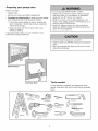 3
3
-
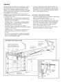 4
4
-
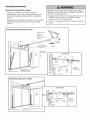 5
5
-
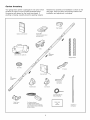 6
6
-
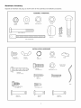 7
7
-
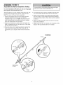 8
8
-
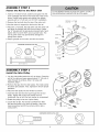 9
9
-
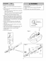 10
10
-
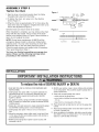 11
11
-
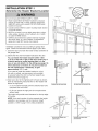 12
12
-
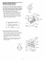 13
13
-
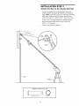 14
14
-
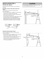 15
15
-
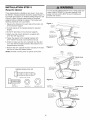 16
16
-
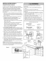 17
17
-
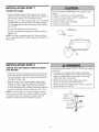 18
18
-
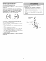 19
19
-
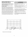 20
20
-
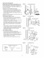 21
21
-
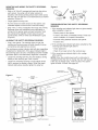 22
22
-
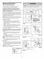 23
23
-
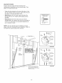 24
24
-
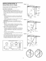 25
25
-
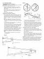 26
26
-
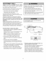 27
27
-
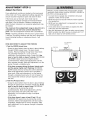 28
28
-
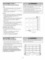 29
29
-
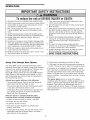 30
30
-
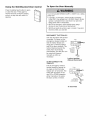 31
31
-
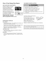 32
32
-
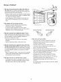 33
33
-
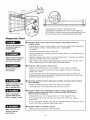 34
34
-
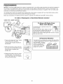 35
35
-
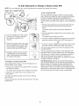 36
36
-
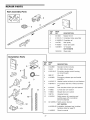 37
37
-
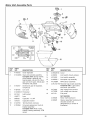 38
38
-
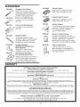 39
39
-
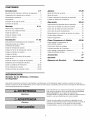 40
40
-
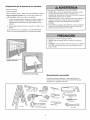 41
41
-
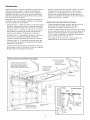 42
42
-
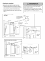 43
43
-
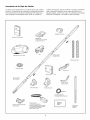 44
44
-
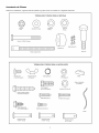 45
45
-
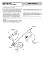 46
46
-
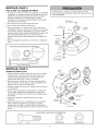 47
47
-
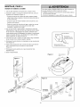 48
48
-
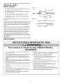 49
49
-
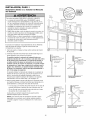 50
50
-
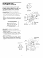 51
51
-
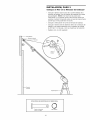 52
52
-
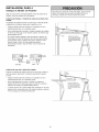 53
53
-
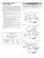 54
54
-
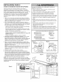 55
55
-
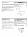 56
56
-
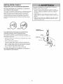 57
57
-
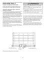 58
58
-
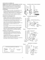 59
59
-
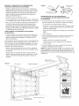 60
60
-
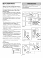 61
61
-
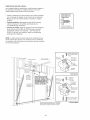 62
62
-
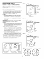 63
63
-
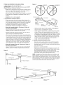 64
64
-
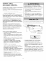 65
65
-
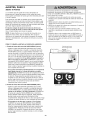 66
66
-
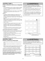 67
67
-
 68
68
-
 69
69
-
 70
70
-
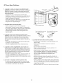 71
71
-
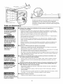 72
72
-
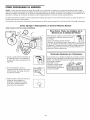 73
73
-
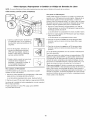 74
74
-
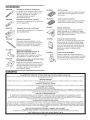 75
75
-
 76
76


Craftsman 13953930DM El manual del propietario
- Categoría
- Abridor de puerta de garage
- Tipo
- El manual del propietario
en otros idiomas
- English: Craftsman 13953930DM Owner's manual
Artículos relacionados
-
Craftsman 139.53930DM El manual del propietario
-
-
-
-
-
-
-
-
-