Sony UNIOFL7C2 Instrucciones de operación
- Categoría
- Accesorios para cámaras de seguridad
- Tipo
- Instrucciones de operación
Este manual también es adecuado para
La página se está cargando ...
La página se está cargando ...
La página se está cargando ...

UNI-OFL7C2
UNI-OFL7T2
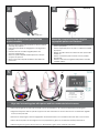
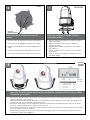
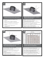
Electrical Specifications
Operating Temperature Specifications
(ONLY AL AIRE LIBRE):
UNI-ONL7C2 y UNI-ONL7T2
26 vatios en 24VAC (calentador y soplador)
Aproximadamente el 25 Watts a 24 VCA (cámara) *
* Consulte con las especificaciones de la cámara aplicable para el consumo precisa.
Herramientas Requeridas: Destornillador PrincipalPhillips
Del Destornillador Principal Plano Del 100"
(ONLY EXTÉRIEURS):
UNI-ONL7C2 et UNI-ONL7T2
26 watts à 24VAC (réchauffeur et ventilateur)
Environ 25 Watts à 24 VAC (caméra seulement) *
* Se reporter aux spécifications applicables à la consommation caméra précis.
Outils Requis: Tournevis Principal Phillips
De Tournevis Principal Plat De 100"
(IM FREIEN ONLY):
UNI-ONL7C2 u. UNI-ONL7T2
26 Watt an 24VAC (Heizung und Gebläse)
Etwa 25 W bei 24 VAC (Kamera) *
* Wenden Sie sich an geltenden Kamera Angaben zur genauen Verbrauch.
Werkzeuge Erforderten: 100"Flacher Hauptschraubenzieher-
Kreuzkopfhauptschraubenzieher
(ONLY AO AR LIVRE):
UNI-ONL7C2 & UNI-ONL7T2
26 watts em 24VAC (calefator e ventilador)
2Cerca de 25 Watts a 24 VCA (Camera Only) *
* Consulte a Ficha câmera aplicável ao consumo precisa.
As Ferramentas Requereram: Chave de fenda Principal
Phillips Da Chave de fenda Principal Lisa Do 100"
(ONLY ESTERNI):
UNI-ONL7C2 & UNI-ONL7T2
26 watt a 24VAC (riscaldatore e ventilatore)
Circa 25 Watt a 24 VAC (solo fotocamera) *
* Fare riferimento a specifiche fotocamera applicabili per il consumo precise.
Attrezzi Richiesti: Cacciavite Capo "phillips" Del Cacciavite
Capo Piano Del 100"
-20°C to +50°C (-4°F to +122°F)
(OUTDOOR ONLY):
UNI-OFL7C2 & UNI-OFL7T2
Power 24VAC, Class 2 Only
26 Watts at 24 VAC (Heater and Blower)
Approximately 25 Watts at 24 VAC (Camera)*
*Refer to applicable camera specs for price consumption
Tools Required: .100" Flat Head Screwdriver
Phillips Head Screwdriver
MM
2
AWG
,5 ,75 1,0 1,5 2,5 4 6
22 20 18 16 14 12 10
The beam angle may be adjusted on the
bottom of the unit.
• Éstos se recomiendan las distancias máximas para
24VAC con una gota del voltage del 10%.
• Ceux-ci sont recommandés des distances maximum
pour 24VAC avec une baisse de volatage de 10%.
• Diese werden maximale Abstände für 24VAC mit einem
das 10% volatage Tropfen empfohlen.
• Estes são recomendados distâncias máximas para
24VAC com uma gota do volatage de 10%.
• Questi sono suggeriti distanze massime per 24VAC con
una goccia di volatage di 10%.
These are recommended maximum distances
for 24VAC with a 10% voltage drop.
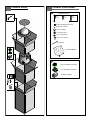
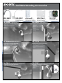
Location of housing components
• Localización de los componentes de la cubierta
• Endroit des composants de logement
• Position der Gehäusebestandteile
• Posição de componentes da carcaça
• Posizione delle componenti dell'alloggiamento
FANS
(HEATERS BEHIND
BRACKETS)
MOUNTING
PLATE
24VAC - 12VDC
POWER SUPPLY
1
2
La página se está cargando ...
La página se está cargando ...
La página se está cargando ...

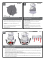
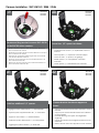
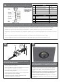
Use wire cutter to cup off top section of PCB
clips
• Utilice el cortador de alambre para ahuecar de la
sección superior de los clips del PWB
• Utilisez le coupeur de fil pour mettre en forme de tasse
outre de la section supérieure des agrafes de carte
• Benutzen Sie Drahtschneider, um weg vom Spitzenab-
schnitt der PWB-Klipps zu höhlen
• Use o cortador de fio para colocar fora da seção
superior de grampos do PWB
• Utilizzi la trinciatrice di cavo per foggiare a coppa fuori
dalla sezione superiore delle clip del PWB
SNCRX550
Remove power supply from bracket
assembly
• Quite la fuente de alimentación del montaje de
soporte
• Enlevez l'alimentation d'énergie du support
• Entfernen Sie Spg.Versorgungsteil vom Haltewinkel
• Remova a fonte de alimentação do conjunto de
suporte
• Rimuova l'alimentazione elettrica dal complessivo
staffa
SNCRX550
Move Red & Orange 24VAC wires to the side
of the bracket
• Mueva el & rojo; Alambres anaranjados 24VAC al lado
del soporte
• Déplacez le & rouge ; Fils 24VAC oranges au côté de la
parenthèse
• Verschieben Sie rotes & Orange Drähte 24VAC zur Seite
des Haltewinkels
• Mova o & vermelho; Fios 24VAC alaranjados ao lado
do suporte
• Sposti il & rosso; Legare arancioni 24VAC al lato della
staffa
SNCRX550
12
13
14 15

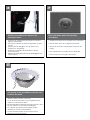
Remove the quick release plate from the
packet.
• Quite la placa del lanzamiento rápido del paquete.
• Enlevez le plat de dégagement rapide du paquet.
• Entfernen Sie die Platte der schnellen Freigabe vom
Paket.
• Remova a placa rápida da liberação da carcaça.
• Rimuova il piatto del rilascio rapido dal pacchetto.
SNC RX550
MOUNTING HOLES
SNCRX550
SNCRX550
Mount the camera to the plate using the
appropriate pattern.
• Monte la cámara fotográfica a la placa usando el
patrón apropiado.
• Montez l'appareil-photo au plat en utilisant le
modèle approprié.
• Bringen Sie die Kamera zur Platte mit dem passen-
den Muster an.
• Monte a câmera à placa usando o teste padrão
apropriado.
• Monti la macchina fotografica alla piastra usando
il modello adatto.
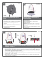
Align tabs in mounting plate with the base plate and turn counterclockwise to secure. When
completed, go to step 27.
• Alinee las lengüetas en placa de montaje con el embase y dé vuelta a la izquierda para asegurar. Cuando se
haya completado, vaya al paso 27.
• Alignez les étiquettes dans le plat de support avec l'embase et tournez dans le sens contraire des aiguilles d'une
montre pour fixer. Une fois terminé, passez à l'étape 27.
• Richten Sie Vorsprünge in der Montageplatte mit der Grundplatte aus und drehen Sie nach links, um zu sichern.
Wenn der Vorgang abgeschlossen, gehen Sie bis 27 Schritt.
• Alinhe abas na placa de montagem com a placa baixa e gire-as no sentido anti-horário para fixar-se. Quando
estiver concluída, vá para a etapa 27.
• Allinei le linguette in giunto di supporto con la base di appoggio e giri in senso antiorario per fissare. Una volta
completato, andare al passaggio 27.
SNC-RX530
SNC-RX550
SNC-RX570
Sensor Input/Output Violet
Sensor Input/Output Gray
16
17
18

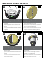
Camera Installation: SNC-RH124 / RS44 / RS46
Remove existing bracket to mount SNC-RH124
or the SNC-RS series cameras.
• Retire el soporte existentes para organizar SNC-RH124 o la
SNC-cámaras de la serie RS.
• Retirez le support afin de faire face SNC-RH124 ou le Groupe
SNC-caméras de la série RS.
• Entfernen Sie vorhandene Halterung an SNC-mount-RH124
oder die SNC-RS-Serie Kameras.
• Remover suporte existente para montar SNC-RH124 ou do
SNC câmeras da série RS.
• Rimuovere supporto esistente per montare SNC-RH124 o la
SNC-telecamere della serie RS.
SNC-RH124
SNC-RS44
SNC-RS46
Leave four 1/2” spacers as shown.
• Vacaciones de cuatro 1 / 2 "separadores como se
muestra.
• Laissez quatre 1 / 2 "espaceurs comme indiqué.
• Lassen Sie vier 1 / 2 "Spacer, wie gezeigt.
• Deixar quatro 1 / 2 "espaçadores, conforme
mostrado.
• Lascia quattro 1 / 2 "distanziali come mostrato.
SNC-RH124
SNC-RS44
SNC-RS46
Add four additional 1/2” spacers.
• Agregue cuatro adicional de 1 / 2 "espaciadores.
• Ajoutez quatre supplémentaire de 1 / 2 "entretoises.
• Fügen Sie vier weitere 1 / 2 "Abstandshalter.
• Adicionar quatro adicional de 1 / 2 "espaçadores.
• Aggiungere quattro ulteriori 1 / 2 "distanziali.
SNC-RH124
SNC-RS44
SNC-RS46
Camera bracket should now appear as
shown.
• Soporte de cámara Shaud ahora aparecen como se
muestra.
• Support pour caméra devrait maintenant s'afficher
comme indiqué.
• Kamerahalterung shoud jetzt wie abgebildet
angezeigt.
• Suporte de câmera shoud agora aparecerá como
mostrado.
• Staffa Camera shoud ora appaiono come mostrato.
SNC-RH124
SNC-RS44
SNC-RS46
20
19
21 22

Attach the SNC RH124 ceiling plate to 1” (25mm)
spacers in housing
• Ate la placa del techo de SNC RH124” a los espaciadores 1 (de 25m
m) en la cubierta
• Attachez le plat de plafond de SNC RH124 » aux entretoises 1 (de
25mm) dans le logement
• Bringen Sie SNC RH124 Deckenplatte zu“ (25mm) Distanzscheiben 1 im
Gehäuse an
• Una a placa do teto de SNC RH124” aos espaçadores 1 (de 25mm)
na carcaça
• Attacchi il piatto del soffitto di SNC RH124„ ai distanziatori 1 (di 25mm)
in alloggiamento
Connect control and power wires to camera
base, (see Sony camera instructions)
• Conecte el control y accione los alambres a la base de la cámara,
(véase las instrucciones de la cámara de Sony)
• Reliez la commande et actionnez les fils à la base d'appareil-photo,
(voir les instructions d'appareil-photo de Sony)
• Schließen Sie Steuerung an und treiben Sie Drähte zur Kameraunter-
seite an, (sehen Sie Sony-Kameraanweisungen)
• Conecte o controle e pnha fios à base da câmera, (veja instruções
da câmera de Sony)
• Colleghi il controllo ed alimenti i legare alla base della macchina
fotografica, (vedi le istruzioni della macchina fotografica di Sony)
24VAC Power
RJ45
Attach base plate to ceiling plate with hardware
provided with camera
• El embase de la fijación a la placa del techo con hardware
proporcionó la cámara
• L'embase d'attache au plat de plafond avec le matériel a fourni en
appareil-photo
• Grundplatte der Befestigungs zur Deckenplatte mit Hardware versah
mit Kamera
• A placa baixa do anexo à placa do teto com ferragem forneceu
com a câmera
• La base di appoggio dell'attaccatura al piatto del soffitto con fissaggi
ha fornito la macchina fotografica
Attach main connector and install camera to
base plate. Secure locking pins
• Ate el conectador principal e instale la cámara al embase. Asegure
las clavijas de cierre
• Attachez le connecteur principal et installez l'appareil-photo sur
l'embase. Fixez les chevilles de verrouillage
• Bringen Sie Hauptverbindungsstück an und bringen Sie Kamera zur
Grundplatte an. Sichern Sie Sicherungsstifte
• Una o conector principal e instale a câmera à placa baixa. Fixe os
pinos de travamento
• Attacchi il connettore principale ed installi la macchina fotografica
alla base di appoggio. Fissi i perni di bloccaggio
Camera Installation: SNC-RH124 / RS44 / RS46 Cont.
SNC-RH124
SNC-RS44
SNC-RS46
SNC-RH124
SNC-RS44
SNC-RS46
SNC-RH124
SNC-RS44
SNC-RS46
SNC-RH124
SNC-RS44
SNC-RS46
23
24
25 26

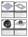
1
Using the provided template, mark the
ceiling tile for the cutout.
• Con la plantilla proporcionada, cortar el azulejo del
techo para el agujero.
• En utilisant le calibre fourni, marquez la tuile de
plafond pour le coupe-circuit.
• Mit der zur Verfügung gestellten Schablone
kennzeichnen Sie die Decke Fliese für den Ausschnitt.
• Usando o molde fornecido, marque a telha do teto
para o entalhe.
• Usando la mascherina fornita, contrassegni le
mattonelle del soffitto per il ritaglio.
2
A box cutter or jigsaw can be used for
cutting the circle.
• Un cortador o un rompecabezas de la caja se
puede utilizar para cortar el círculo.
• Un coupeur ou une scie sauteuse de boîte peut
être utilisé pour couper le cercle.
• Ein Kastenscherblock oder -tischlerbandsäge
können für den Schnitt des Kreises benutzt werden.
• Um cortador ou um jigsaw da caixa podem ser
usados cortando o círculo.
• Una taglierina o un jigsaw della scatola può essere
utilizzato per il taglio del cerchio.
3
Add spacers to the plate in order to appropri-
ately position the camera, see specific camera.
• Agregue los espaciadores a la placa para colocar apropiada-
mente la cámara fotográfica, vea la cámara fotográfica
específica.
• Ajoutez les entretoises au plat afin de placer convenablement
l'appareil-photo, voyez l'appareil-photo spécifique.
• Fügen Sie Distanzscheiben der Platte hinzu, um die Kamera
passend in Position zu bringen, sehen Sie spezifische Kamera.
• Adicione espaçadores à placa a fim posicionar apropriada-
mente a câmera, veja a câmera específica.
• Aggiunga i distanziatori alla piastra per posizionare giusta-
mente la macchina fotografica, veda la macchina fotografica
specifica.
4
Place the housing in the tile and secure the
outer tabs.
• Coloque la cubierta en el azulejo y asegure las
lengüetas externas.
• Placez le logement dans la tuile et fixez les étiquettes
externes.
• Legen Sie das Gehäuse in die Fliese und sichern Sie
die äußeren Vorsprünge.
• Coloque a carcaça na telha e fixe as abas exteriores.
• Disponga l'alloggiamento nelle mattonelle ed assicuri
le linguette esterne.
27
28
29
30
La página se está cargando ...

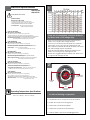
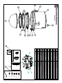
Jumpers
Input
Wires from
Dome
Green
Yellow
Orange
Red
Add 2 jumpers if using a common power supply for
the camera, heater & blower.
• Añadir 2 jumpers si utiliza una fuente de alimentación para la
cámara, calefacción y ventilador.
• Ajoutez 2 cavaliers si vous utilisez une alimentation pour l'appareil
photo, appareil de chauffage et de soufflerie.
• Add 2 Jumper, wenn Sie eine gemeinsame Stromversorgung für
die Kamera, Heizung & Gebläse.
• Adicionar 2 jumpers comum se utilizar uma fonte de alimentação
para a câmara, aquecedor e ventilador.
• Aggiungere 2 ponticelli se si utilizza un alimentatore per la
fotocamera, riscaldamento e ventilatore.
+
-
RJ45
BNC
24VAC
1
2
3
4
Camera
Camera
Heater/Blower
Heater/Blower
Red
Orange
Yellow
Green
POWER
Max 40 Watts
52 Watts
1/0
1
2
3
4
Alarm 1
Alarm 2
Alarm 3
Common
Blue
Violet
Gray
White
Make the appropriate male and female connections. Indoor model does not include pre-run cables.
• Haga las conexiones masculinas y femeninas apropiadas. El modelo de interior no incluye pre-funciona los cables.
• Établissez les rapports masculins et femelles appropriés. Le modèle d'intérieur n'inclut pas pré-courent des câbles.
• Stellen Sie die passenden männlichen und weiblichen Beziehungen her. Innenmodell schließt nicht vor-laufen lassen Kabel
ein.
• Faça as conexões masculinas e fêmeas apropriadas. O modelo indoor não inclui pre-funciona cabos.
• Faccia i collegamenti maschii e femminili adatti. Il modello dell'interno non include pre-fa funzionare i cavi.
RJ45
(Large)
POWER
(Small)
POWER
BNC
Power and Control Inputs (Outside of Housing)
24Vdc
1 Camera Power (+ 24 VDC) Red
2 Camera Power (- 24 VDC) Orange
3 Accessory Power (+ 24 VDC) Yellow
4 Accessory Power (- 24 VDC) Green
CONTROL RJ45 Ethernet Connector
1/0
1 Alarm 1 Blue
2 Alarm 2 Violet
3 Alarm 3 Gray
4 Common White
The beam angle may be adjusted on the bottom of the unit.
• Instale la cámara fotográfica en la cubierta y termine los usos del
cableado. Vea las especificaciones de la cámara fotográfica.
• Installez l'appareil-photo dans le logement et accomplissez les
applications de câblage. Voir les caractéristiques d'appareil-
photo.
• Bringen Sie die Kamera in das Gehäuse an und führen Sie Verdrah-
tung Anwendungen durch. Sehen Sie Kameraspezifikationen.
• Instale a câmera na carcaça e termine aplicações da fiação.
Veja especificações da câmera.
• Installi la macchina fotografica nell'alloggiamento e completi le
applicazioni dei collegamenti. Veda le specifiche della macchina
fotografica.
11
Install the camera in the housing and complete
wiring applications. See camera specifications.
Refer to camera
product manuals
regarding power
consumption.
37
35
36

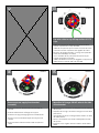
The beam angle may be adjusted on the
bottom of the unit.
• Enganche el acollador de la bóveda a la cubierta
según lo demostrado.
• Accrochez la lanière du dôme au logement comme
montré.
• Spannen Sie die Abzuglinie von der Haube zum
Gehäuse an, wie gezeigt.
• Enganche o colhedor da abóbada à carcaça
como mostrada.
• Agganci la cordicella dalla cupola all'alloggiamento
come indicato.
12
Hook the lanyard from the dome to the
housing as shown.
13
beam angle may be adjusted on the bttom
o the unit.
• Asegure la bóveda con los tornillos ya en la bóveda.
• Fixez le dôme avec des vis déjà dans le dôme.
• Sichern Sie die Haube mit Schrauben bereits in der
Haube.
• Fixe a abóbada com parafusos já na abóbada.
• Fissi la cupola con le viti già nella cupola.
Secure the dome with screws already
in the dome.
• Los tornillos de la seguridad proporcionados se pueden
también utilizar para unir la bóveda.
• Les vis de sécurité fournies peuvent également être
utilisées pour attacher le dôme.
• Die bereitgestellten Sicherheit Schrauben können auch
benutzt werden, um die Haube anzubringen.
• Os parafusos da segurança fornecidos podem
também ser usados unir a abóbada.
• Le viti di sicurezza fornite possono anche essere
utilizzate per fissare la cupola.
14
The security screws provided can also be used
to attach the dome.
38
40
39
La página se está cargando ...
La página se está cargando ...
La página se está cargando ...
La página se está cargando ...
Transcripción de documentos
Electrical Specifications UNI-OFL7C2 UNI-OFL7T2 1 ,5 22 ,75 20 1,0 18 1,5 16 2,5 14 4 12 6 10 MM2 AWG Power 24VAC, Class 2 Only (OUTDOOR ONLY): UNI-OFL7C2 & UNI-OFL7T2 26 Watts at 24 VAC (Heater and Blower) Approximately 25 Watts at 24 VAC (Camera)* *Refer to applicable camera specs for price consumption Tools Required: .100" Flat Head Screwdriver Phillips Head Screwdriver (ONLY AL AIRE LIBRE): UNI-ONL7C2 y UNI-ONL7T2 26 vatios en 24VAC (calentador y soplador) Aproximadamente el 25 Watts a 24 VCA (cámara) * * Consulte con las especificaciones de la cámara aplicable para el consumo precisa. Herramientas Requeridas: Destornillador PrincipalPhillips Del Destornillador Principal Plano Del 100" (ONLY EXTÉRIEURS): UNI-ONL7C2 et UNI-ONL7T2 26 watts à 24VAC (réchauffeur et ventilateur) Environ 25 Watts à 24 VAC (caméra seulement) * * Se reporter aux spécifications applicables à la consommation caméra précis. Outils Requis: Tournevis Principal Phillips De Tournevis Principal Plat De 100" (IM FREIEN ONLY): UNI-ONL7C2 u. UNI-ONL7T2 26 Watt an 24VAC (Heizung und Gebläse) Etwa 25 W bei 24 VAC (Kamera) * * Wenden Sie sich an geltenden Kamera Angaben zur genauen Verbrauch. The beam angle may be adjusted the These are recommended maximumon distances bottom of with the unit. for 24VAC a 10% voltage drop. • Éstos se recomiendan las distancias máximas para 24VAC con una gota del voltage del 10%. • Ceux-ci sont recommandés des distances maximum pour 24VAC avec une baisse de volatage de 10%. • Diese werden maximale Abstände für 24VAC mit einem das 10% volatage Tropfen empfohlen. • Estes são recomendados distâncias máximas para 24VAC com uma gota do volatage de 10%. • Questi sono suggeriti distanze massime per 24VAC con una goccia di volatage di 10%. Werkzeuge Erforderten: 100"Flacher HauptschraubenzieherKreuzkopfhauptschraubenzieher (ONLY AO AR LIVRE): UNI-ONL7C2 & UNI-ONL7T2 26 watts em 24VAC (calefator e ventilador) 2Cerca de 25 Watts a 24 VCA (Camera Only) * * Consulte a Ficha câmera aplicável ao consumo precisa. As Ferramentas Requereram: Chave de fenda Principal Phillips Da Chave de fenda Principal Lisa Do 100" 2 (ONLY ESTERNI): UNI-ONL7C2 & UNI-ONL7T2 26 watt a 24VAC (riscaldatore e ventilatore) Circa 25 Watt a 24 VAC (solo fotocamera) * 24VAC - 12VDC POWER SUPPLY * Fare riferimento a specifiche fotocamera applicabili per il consumo precise. Attrezzi Richiesti: Cacciavite Capo "phillips" Del Cacciavite Capo Piano Del 100" MOUNTING PLATE Operating Temperature Specifications -20°C to +50°C (-4°F to +122°F) FANS (HEATERS BEHIND BRACKETS) Location of housing components • Localización de los componentes de la cubierta • Endroit des composants de logement • Position der Gehäusebestandteile • Posição de componentes da carcaça • Posizione delle componenti dell'alloggiamento 12 13 SNCRX550 Use wire cutter to cup off top section of PCB clips • Utilice el cortador de alambre para ahuecar de la sección superior de los clips del PWB • Utilisez le coupeur de fil pour mettre en forme de tasse outre de la section supérieure des agrafes de carte • Benutzen Sie Drahtschneider, um weg vom Spitzenabschnitt der PWB-Klipps zu höhlen • Use o cortador de fio para colocar fora da seção superior de grampos do PWB • Utilizzi la trinciatrice di cavo per foggiare a coppa fuori dalla sezione superiore delle clip del PWB 14 SNCRX550 Remove power supply from bracket assembly • Quite la fuente de alimentación del montaje de soporte • Enlevez l'alimentation d'énergie du support • Entfernen Sie Spg.Versorgungsteil vom Haltewinkel • Remova a fonte de alimentação do conjunto de suporte • Rimuova l'alimentazione elettrica dal complessivo staffa 15 SNCRX550 Move Red & Orange 24VAC wires to the side of the bracket • Mueva el & rojo; Alambres anaranjados 24VAC al lado del soporte • Déplacez le & rouge ; Fils 24VAC oranges au côté de la parenthèse • Verschieben Sie rotes & Orange Drähte 24VAC zur Seite des Haltewinkels • Mova o & vermelho; Fios 24VAC alaranjados ao lado do suporte • Sposti il & rosso; Legare arancioni 24VAC al lato della staffa 16 SNCRX550 17 SNCRX550 SNC RX550 MOUNTING HOLES Remove the quick release plate from the packet. Mount the camera to the plate using the appropriate pattern. • Quite la placa del lanzamiento rápido del paquete. • Monte la cámara fotográfica a la placa usando el patrón apropiado. • Montez l'appareil-photo au plat en utilisant le modèle approprié. • Bringen Sie die Kamera zur Platte mit dem passenden Muster an. • Monte a câmera à placa usando o teste padrão apropriado. • Monti la macchina fotografica alla piastra usando il modello adatto. • Enlevez le plat de dégagement rapide du paquet. • Entfernen Sie die Platte der schnellen Freigabe vom Paket. • Remova a placa rápida da liberação da carcaça. • Rimuova il piatto del rilascio rapido dal pacchetto. SNC-RX530 SNC-RX550 SNC-RX570 18 Sensor Input/Output Sensor Input/Output Violet Gray Align tabs in mounting plate with the base plate and turn counterclockwise to secure. When completed, go to step 27. • Alinee las lengüetas en placa de montaje con el embase y dé vuelta a la izquierda para asegurar. Cuando se haya completado, vaya al paso 27. • Alignez les étiquettes dans le plat de support avec l'embase et tournez dans le sens contraire des aiguilles d'une montre pour fixer. Une fois terminé, passez à l'étape 27. • Richten Sie Vorsprünge in der Montageplatte mit der Grundplatte aus und drehen Sie nach links, um zu sichern. Wenn der Vorgang abgeschlossen, gehen Sie bis 27 Schritt. • Alinhe abas na placa de montagem com a placa baixa e gire-as no sentido anti-horário para fixar-se. Quando estiver concluída, vá para a etapa 27. • Allinei le linguette in giunto di supporto con la base di appoggio e giri in senso antiorario per fissare. Una volta completato, andare al passaggio 27. Camera Installation: SNC-RH124 / RS44 / RS46 19 SNC-RH124 SNC-RS44 SNC-RS46 Remove existing bracket to mount SNC-RH124 or the SNC-RS series cameras. • Retire el soporte existentes para organizar SNC-RH124 o la SNC-cámaras de la serie RS. • Retirez le support afin de faire face SNC-RH124 ou le Groupe SNC-caméras de la série RS. • Entfernen Sie vorhandene Halterung an SNC-mount-RH124 oder die SNC-RS-Serie Kameras. • Remover suporte existente para montar SNC-RH124 ou do SNC câmeras da série RS. • Rimuovere supporto esistente per montare SNC-RH124 o la SNC-telecamere della serie RS. 21 SNC-RH124 SNC-RS44 SNC-RS46 Add four additional 1/2” spacers. • Agregue cuatro adicional de 1 / 2 "espaciadores. • Ajoutez quatre supplémentaire de 1 / 2 "entretoises. • Fügen Sie vier weitere 1 / 2 "Abstandshalter. • Adicionar quatro adicional de 1 / 2 "espaçadores. • Aggiungere quattro ulteriori 1 / 2 "distanziali. 20 SNC-RH124 SNC-RS44 SNC-RS46 Leave four 1/2” spacers as shown. • Vacaciones de cuatro 1 / 2 "separadores como se muestra. • Laissez quatre 1 / 2 "espaceurs comme indiqué. • Lassen Sie vier 1 / 2 "Spacer, wie gezeigt. • Deixar quatro 1 / 2 "espaçadores, conforme mostrado. • Lascia quattro 1 / 2 "distanziali come mostrato. 22 SNC-RH124 SNC-RS44 SNC-RS46 Camera bracket should now appear as shown. • Soporte de cámara Shaud ahora aparecen como se muestra. • Support pour caméra devrait maintenant s'afficher comme indiqué. • Kamerahalterung shoud jetzt wie abgebildet angezeigt. • Suporte de câmera shoud agora aparecerá como mostrado. • Staffa Camera shoud ora appaiono come mostrato. Camera Installation: SNC-RH124 / RS44 / RS46 Cont. 23 SNC-RH124 SNC-RS44 SNC-RS46 24 SNC-RH124 SNC-RS44 SNC-RS46 24VAC Power RJ45 Attach the SNC RH124 ceiling plate to 1” (25mm) spacers in housing Connect control and power wires to camera base, (see Sony camera instructions) • Ate la placa del techo de SNC RH124” a los espaciadores 1 (de 25m m) en la cubierta • Conecte el control y accione los alambres a la base de la cámara, (véase las instrucciones de la cámara de Sony) • Attachez le plat de plafond de SNC RH124 » aux entretoises 1 (de 25mm) dans le logement • Reliez la commande et actionnez les fils à la base d'appareil-photo, (voir les instructions d'appareil-photo de Sony) • Bringen Sie SNC RH124 Deckenplatte zu“ (25mm) Distanzscheiben 1 im Gehäuse an • Schließen Sie Steuerung an und treiben Sie Drähte zur Kameraunterseite an, (sehen Sie Sony-Kameraanweisungen) • Una a placa do teto de SNC RH124” aos espaçadores 1 (de 25mm) na carcaça • Conecte o controle e pnha fios à base da câmera, (veja instruções da câmera de Sony) • Attacchi il piatto del soffitto di SNC RH124„ ai distanziatori 1 (di 25mm) in alloggiamento • Colleghi il controllo ed alimenti i legare alla base della macchina fotografica, (vedi le istruzioni della macchina fotografica di Sony) 25 SNC-RH124 SNC-RS44 SNC-RS46 Attach base plate to ceiling plate with hardware provided with camera 26 SNC-RH124 SNC-RS44 SNC-RS46 Attach main connector and install camera to base plate. Secure locking pins • El embase de la fijación a la placa del techo con hardware proporcionó la cámara • Ate el conectador principal e instale la cámara al embase. Asegure las clavijas de cierre • L'embase d'attache au plat de plafond avec le matériel a fourni en appareil-photo • Attachez le connecteur principal et installez l'appareil-photo sur l'embase. Fixez les chevilles de verrouillage • Grundplatte der Befestigungs zur Deckenplatte mit Hardware versah mit Kamera • Bringen Sie Hauptverbindungsstück an und bringen Sie Kamera zur Grundplatte an. Sichern Sie Sicherungsstifte • A placa baixa do anexo à placa do teto com ferragem forneceu com a câmera • Una o conector principal e instale a câmera à placa baixa. Fixe os pinos de travamento • La base di appoggio dell'attaccatura al piatto del soffitto con fissaggi ha fornito la macchina fotografica • Attacchi il connettore principale ed installi la macchina fotografica alla base di appoggio. Fissi i perni di bloccaggio 1 27 28 2 Using the provided template, mark the ceiling tile for the cutout. A box cutter or jigsaw can be used for cutting the circle. • Con la plantilla proporcionada, cortar el azulejo del • Un cortador o un rompecabezas de la caja se puede utilizar para cortar el círculo. • Un coupeur ou une scie sauteuse de boîte peut être utilisé pour couper le cercle. • Ein Kastenscherblock oder -tischlerbandsäge können für den Schnitt des Kreises benutzt werden. • Um cortador ou um jigsaw da caixa podem ser usados cortando o círculo. • Una taglierina o un jigsaw della scatola può essere utilizzato per il taglio del cerchio. techo para el agujero. • En utilisant le calibre fourni, marquez la tuile de plafond pour le coupe-circuit. • Mit der zur Verfügung gestellten Schablone kennzeichnen Sie die Decke Fliese für den Ausschnitt. • Usando o molde fornecido, marque a telha do teto para o entalhe. • Usando la mascherina fornita, contrassegni le mattonelle del soffitto per il ritaglio. 29 3 Add spacers to the plate in order to appropriately position the camera, see specific camera. 30 4 Place the housing in the tile and secure the outer tabs. • Agregue los espaciadores a la placa para colocar apropiada- • Coloque la cubierta en el azulejo y asegure las lengüetas externas. • • Placez le logement dans la tuile et fixez les étiquettes externes. • • • mente la cámara fotográfica, vea la cámara fotográfica específica. Ajoutez les entretoises au plat afin de placer convenablement l'appareil-photo, voyez l'appareil-photo spécifique. Fügen Sie Distanzscheiben der Platte hinzu, um die Kamera passend in Position zu bringen, sehen Sie spezifische Kamera. Adicione espaçadores à placa a fim posicionar apropriadamente a câmera, veja a câmera específica. Aggiunga i distanziatori alla piastra per posizionare giustamente la macchina fotografica, veda la macchina fotografica specifica. • Legen Sie das Gehäuse in die Fliese und sichern Sie die äußeren Vorsprünge. • Coloque a carcaça na telha e fixe as abas exteriores. • Disponga l'alloggiamento nelle mattonelle ed assicuri le linguette esterne. 35 24Vdc Power and Control Inputs (Outside of Housing) 1 Refer to camera product manuals regarding power consumption. RJ45 (Large) POWER 2 RJ45Camera Power (+ 24 VDC) 24VAC Camera Power (- 24 VDC) 1 3 2 3 4 4 Camera Red Accessory VDC) Camera Power (+ 24Orange Heater/Blower Accessory Power (- 24 Yellow VDC) Heater/Blower Green CONTROL RJ45 Ethernet Connector 1/0 (Small) POWER 1 1 2 2 3 3 4 Alarm 1 Alarm 1 Alarm 2 Alarm 2 Alarm 3 Alarm 3 Common BNC 4 Common Red POWER Orange Max 40 Watts Yellow 52Green Watts 1/0 Blue Violet Gray White BNC Blue Violet Gray White Make the appropriate male and female connections. Indoor model does not include pre-run cables. • Haga las conexiones masculinas y femeninas apropiadas. El modelo de interior no incluye pre-funciona los cables. • Établissez les rapports masculins et femelles appropriés. Le modèle d'intérieur n'inclut pas pré-courent des câbles. • Stellen Sie die passenden männlichen und weiblichen Beziehungen her. Innenmodell schließt nicht vor-laufen lassen Kabel ein. • Faça as conexões masculinas e fêmeas apropriadas. O modelo indoor não inclui pre-funciona cabos. • Faccia i collegamenti maschii e femminili adatti. Il modello dell'interno non include pre-fa funzionare i cavi. 36 Green Jumpers Wires from Dome Yellow 37 11 Orange Red Input - + Add 2 jumpers if using a common power supply for the camera, heater & blower. • Añadir 2 jumpers si utiliza una fuente de alimentación para la cámara, calefacción y ventilador. • Ajoutez 2 cavaliers si vous utilisez une alimentation pour l'appareil photo, appareil de chauffage et de soufflerie. • Add 2 Jumper, wenn Sie eine gemeinsame Stromversorgung für die Kamera, Heizung & Gebläse. • Adicionar 2 jumpers comum se utilizar uma fonte de alimentação para a câmara, aquecedor e ventilador. • Aggiungere 2 ponticelli se si utilizza un alimentatore per la fotocamera, riscaldamento e ventilatore. The beam angle may be adjusted on the bottom of the unit. Install the camera in the housing and complete wiring applications. See camera specifications. • Instale la cámara fotográfica en la cubierta y termine los usos del cableado. Vea las especificaciones de la cámara fotográfica. • Installez l'appareil-photo dans le logement et accomplissez les applications de câblage. Voir les caractéristiques d'appareilphoto. • Bringen Sie die Kamera in das Gehäuse an und führen Sie Verdrahtung Anwendungen durch. Sehen Sie Kameraspezifikationen. • Instale a câmera na carcaça e termine aplicações da fiação. Veja especificações da câmera. • Installi la macchina fotografica nell'alloggiamento e completi le applicazioni dei collegamenti. Veda le specifiche della macchina fotografica. 12 38 13 39 The beam angle may be adjusted on the Hook the lanyard from the dome to the housing as shown. bottom of the unit. beamthe angle may bescrews adjusted on the bttom Secure dome with already inothe dome. the unit. • Enganche el acollador de la bóveda a la cubierta según lo demostrado. • Accrochez la lanière du dôme au logement comme montré. • Spannen Sie die Abzuglinie von der Haube zum Gehäuse an, wie gezeigt. • Enganche o colhedor da abóbada à carcaça como mostrada. • Agganci la cordicella dalla cupola all'alloggiamento come indicato. • Asegure la bóveda con los tornillos ya en la bóveda. 14 40 The security screws provided can also be used to attach the dome. • Los tornillos de la seguridad proporcionados se pueden también utilizar para unir la bóveda. • Les vis de sécurité fournies peuvent également être utilisées pour attacher le dôme. • Die bereitgestellten Sicherheit Schrauben können auch benutzt werden, um die Haube anzubringen. • Os parafusos da segurança fornecidos podem também ser usados unir a abóbada. • Le viti di sicurezza fornite possono anche essere utilizzate per fissare la cupola. • Fixez le dôme avec des vis déjà dans le dôme. • Sichern Sie die Haube mit Schrauben bereits in der Haube. • Fixe a abóbada com parafusos já na abóbada. • Fissi la cupola con le viti già nella cupola.-
 1
1
-
 2
2
-
 3
3
-
 4
4
-
 5
5
-
 6
6
-
 7
7
-
 8
8
-
 9
9
-
 10
10
-
 11
11
-
 12
12
-
 13
13
-
 14
14
-
 15
15
-
 16
16
-
 17
17
-
 18
18
-
 19
19


Sony UNIOFL7C2 Instrucciones de operación
- Categoría
- Accesorios para cámaras de seguridad
- Tipo
- Instrucciones de operación
- Este manual también es adecuado para
En otros idiomas
- français: Sony UNIOFL7C2 Mode d'emploi
- italiano: Sony UNIOFL7C2 Istruzioni per l'uso
- English: Sony UNIOFL7C2 Operating instructions
Documentos relacionados
Otros documentos
-
Prime-Line N 6817 Instrucciones de operación
-
Moog FDW75 SERIES Instrucciones de operación
-
Axis 25735 Manual de usuario
-
Moog Videolarm FDW7 5C8 Instrucciones de operación
-
-
-
-
Moog Videolarm FDP75C2N/AX Installation And Operation Instructions Manual
-
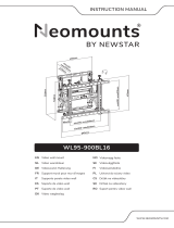 Neomounts WL95-900BL16 Video Wall Mount Manual de usuario
