
User Manual
V1.0 2019 Copyright Safewaze
42” Beam Stanchion For
Horizontal Lifelines
Meets OSHA 1926.502 and 1910.140 Requirements
This manual is intended to meet the Manufacturer’s Instructions as
required by the American National Standards Institute (ANSI) Z359
and should be used as part of an employee training program as
required by the Occupational Safety and Health Act (OSHA).
220-00017

User Manual
V1.0 2019 Copyright Safewaze
1 GENERAL WARNINGS............... ..................... 3
2 INTRODUCTION AND SCOPE OF USE .......... 4
3 APPLICABLE SAFETY STANDARDS .............. 4
4 WORKER CLASSIFICATIONS ......................... 4
5 PRODUCT SPECIFIC APPLICATIONS ............ 5
6 LIMITATIONS .................................................... 5
7 CONNECTIONS ..............................................6-7
8 SPECIFICATIONS ...........................................7-8
9 INSTALLATION AND USE ..............................9-14
10 STANCHION COMPONENTS .......................13-14
11 BEAM CLAMP SIZING CHART & SPECS ...... 15
12 BEAM LOAD REQUIREMENTS TABLE .......... 16
13 INSPECTION AND MAINTENANCE ............... 17
14 INSPECTION LOG .......................................... 18
15 LABELS ........................................................... 19
Page 2
Table of Contents

User Manual
V1.0 2019 Copyright Safewaze
This product is part of a complete fall protection system. This Stanchion product can be used in
conjuction with any Safewaze HLL’s oered, or other HLL systems so long as that system’s anchor
requirements are below 4,000 lbs in order to meet the 2 to 1 safety factor on this 8,000 lbs. anchor
point. User’s must utilize, and connect to a Safewaze HLL system with ANSI Z359 compliant
restraint or Personal Fall Arrest Systems (PFAS). This product is not designed, nor should be used
as a component for a Postioning, Suspension, or Rescue System. A PFAS is typically composed of a
Full Body Harness, Anchorage, and a Connecting Device. Connecting Devices used with Safewaze
HLL’s are Energy Absorbing Lanyards (EAL’s) or a Self Retracting Device (SRD). The connection
point to the FBH for use of a Safewaze HLL is the Dorsal D-ring.
Page 3
WARNING
These instructions must be provided to any person utilizing this equipment. The worker must read
and understand the manufacturer’s instructions for this, and all other components of the complete Fall
Protection System. These instructions must be followed for the proper use, maintenance, and
inspection of this equipment. These instructions must be kept and made available to worker’s at all
times. Any alteration, misuse, or use of this equipment outside the scope of the manufacturer’s
instructions, may result in serious injury or death.
A comprehensive Fall Protection Plan must be kept on le and available to all employees at all times.
The employer and user’s of this equipment must be properly trained in the installation, use,
inspection, and maintenance of this equipment.
The maximum weight capacity of this equipment is 310 lbs. (including tools and equipment) as
specied by ANSI. Certain Safewaze products mentioned in this manual may have maximum weight
capacities in excess of 310 lbs. Although certain components of the overall Personal Fall Arrest
System may have weight weight capacities in excess of 310 lbs., use of the Safewaze Stanchion in a
Horizontal Lifeline System limits the weight of each user to 310 lbs.
Consult your doctor if there is reason to doubt your tness to safely absorb the shock from a fall
arrest. Age and tness seriously aect a worker’s ability to withstand falls. Pregnant women or minors
must not use this equipment. Failure to heed this warning may result in serious injury or death.
User’s of this equipment must read and understand this manual in it’s entirety prior to use.
Contact Safewaze if you have questions, regarding compatibility of this equipment, that are not
covered in this manual. Do not alter or misuse this equipment. Some subsystem components could
aect the performance and the operation of this equipment. Do not anchor this product to moving
machinery, or hazards that have chemical, electrical or gaseous characteristics. Failure to comply
with this warning could result in serious injury or death.

User Manual
V1.0 2019 Copyright Safewaze Page 4
Applicable Safety Standards and Regulations
Worker Classifications
Understand the denitions of those who work in proximity of or may be
exposed to fall hazards.
Qualied Person: A person with an accredidated degree or certication, and with extensive
experience or sucient professional standing, who is considered procient in planning and reviewing
the conformity of fall protection and rescue systems.
Competent Person: A highly trained and experienced person who is assigned by the employer
to be responsible for all elements of a fall safety program, including, but not limited to, its regulation,
management, and application. A person who is procient in identifying existing and predictable
hazards, and who has the authority to stop work in order to eliminate hazards.
Authorized Person: A person who is assigned by their employer to work around or be subject to
potential or existing fall hazards.
It is the responsibility of a Qualied or Competent person to supervise the job site and ensure
safety regulations are complied with.
Introduction & Scope of Use
Thank you for purchasing a Safewaze Stanchion for Horizontal Lifelines (HLL). This manual must be
read and understood in its entirety, and used as part of an employee training program as required by
OSHA or any applicable state agency.
This manual and any other instructional material must be available to the user of the equipment.
The user must understand how to safely and eectively use the Safewaze Stanchion, and all fall
protection equipment used in conjunction with the stanchion.
The Safewaze Stanchion has been designed for your safety. These stanchions, when used in
conjuction with HLL lsystems are designed to oer users a exible and easily removable anchor point.
ANSI Z359.0 Denitions and Nomenclature Used for Fall Protection and Fall Arrest
ANSI Z359.1 Safety Requirements for Personal Fall Arrest Systems, Subsystems, and Components
ANSI Z359.2 Minimum Requirements for a Comprehensive Managed Fall Protection Program
ANSI A10-14 Safety Requirements for Safety Belts, Harnesses, Lanyards, and Lifelines for Construction and
Demolition Use
ANSI A10.32 Personal Fall Protection use in Construction and Demolition
ANSI STANDARDS
OSHA REGULATIONS
OSHA 1910.66 Personal Fall Arrest Systems
OSHA 1926.502 Fall Protection Systems Criteria and Practices

User Manual
V1.0 2019 Copyright Safewaze Page 5
Personal Fall Arrest: Safewaze Stanchions, when installed as part of a HLL System, can be used
as part of a complete Personal Fall Arrest System (PFAS). The maximum number of users is dictated
by the Safewaze HLL system being utilized with the stanchions. The structure utilized for attachment
must be capable of withstanding a load of 5,000 lbs in all directions permitted by the system. The
maximum allowable free fall is 6 ft, with the maximum combined length of the fall arrester, lanyard
extension, and D-ring being 36 inches.
Product Specific Applications
Lanyard Length
(6’ Total)
Deceleration
distance (4’ total)
Height of harness dorsal
D-ring from
worker’s feet
(6’ total)
Safety factor
(2’ total)
Required
distance
from
Anchorage
(18’ total)
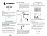
Fall Clearance: There must be sucient clearance below the anchorage connector to arrest a fall
before the user strikes the ground or an obstruction. When calculating fall clearance, account for a
MINIMUM 2’ safety factor, deceleration distance, user height, length of lanyard/SRL, and all other
applicable factors (See Figure 1).
Limitations
Fall Clearance Diagram
***Diagram shown is an example
fall clearance calculation ONLY.
For all applications: worker weight capacity range
(including all clothing, tools, and equipment) is 130-310 lbs
Fig. 1
**USER SHOULD REFER TO HLL INSTRUCTIONS FOR PROPER CLEAR FALL SPECIFICS**

User Manual
V1.0 2019 Copyright Safewaze
Swing Falls: Prior to installation or use, make considerations for eliminating or minimizing all swing
fall hazards. Swing falls occur when the anchor is not directly above the location where a fall occurs.
Always work as close to in line with the anchor point as possible. Swing falls signicantly increase
the likelihood of serious injury or death in the even of a fall. (See Figure 2)
FALLSAFE USA
COMPATIBILITY OF CONNECTIONS
Connectors are compatible with connecting elements when they have been designed to work together
in such a way that their sizes and shapes do not cause their gate mechanisms to inadvertently
open regardless of how they become oriented. Connectors (hooks, carabiners, and D-rings) must
be capable of supporting at least 5,000 lbs. (22.2 kN). Connectors must be compatible with the
anchorage or other system components (see Figure 4). Do not use equipment that is not compatible.
Non- compatible connectors may unintentionally disengage (see Figure 3). Connectors must be
compatible in size, shape, and strength. Self-locking snap hooks and carabiners are required by
ANSI Z359 and OSHA guidelines. Contact Safewaze if you have any questions about compatibility.
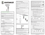
Fig. 3 - UNINTENTIONAL DISENGAGEMENT
Non-compliant part
3 - gate opens
2 - gate presses
against
non-complaint
part
4 - and parts disengage.
1 -
NOTE: SOME SPECIALITY CONNECTORS HAVE ADDITIONAL REQUIREMENTS.
CONTACT Safewaze WITH QUESTIONS.
Fig. 2
Page 6
Using a connector that is undersized or irregular in shape (1) to connect a snap hook or carabiner
could allow the connector to force open the gate of the snap hook or carabiner. When force is applied,
the gate of the hook or carabiner presses against the non-compliant part (2) and forces open the gate
(3). This allows the snap hook or carabiner to disengage (4) from the connection point.
Connections

User Manual
V1.0 2019 Copyright Safewaze Page 7
MAKING CONNECTIONS
Snap hooks and carabiners used with this equipment must be double locking and/or twist lock.
Ensure all connections are compatible in size, shape and strength. Do not use equipment that is not
compatible. Ensure all connectors are fully closed and locked.
Safewaze connectors (snap hooks and carabiners) are designed to be used only as specied in each
product’s user’s instructions. See Fig. 4 for examples of inappropriate connections. Do not connect
snap hooks and carabiners:
• To a D-ring to which another connector is attached.
• In a manner that would result in a load on the gate (with the exception of tie back hooks).
NOTE: Large throat snap hooks must not be connected to standard size D-rings or
similar objects which will result in a load on the gate if the hook or D-ring twists or
rotates, unless the snap hook complies with ANSI Z359.12 and is equipped with a 3,600
lb (16 kN) gate. Check the marking on your snap hook to verify that it is appropriate for
your application.
• In a false engagement, where features that protrude from the snap hook or carabiner catch on the
anchor, and without visual conrmation seems to be fully engaged to the anchor point.
• To each other.
• By wrapping the web lifeline around an anchor and securing to lifeline except as allowed for Tie
Back models.
• To any object which is shaped or sized in a way that the snap hook or carabiner will not close and
lock, or that roll-out could occur.
• In a manner that does not allow the connector to align properly while under load.
Fig. 4 - INAPPROPRIATE CONNECTIONS
Specifications

User Manual
V1.0 2019 Copyright Safewaze Page 8
The Safewaze Stanchion, Horizontal Lifeline system, and its subsystems, must be inspected prior to
each use for:
• Wear, damage, and other deterioration.
• All snaphooks and carabiners must be able to self-close and lock.
• Check the operation of self retracting lanyards by pulling smoothly on the lifeline, then pull sharply
on the lifeline to engage the locking mechanism.
• All rope / wire rope must be inspected for tears, cuts, fraying, abrasion, unsplicing, discoloration,
corrosion, heat damage, bird caging, burrs, kinks, or other signs of wear and damage.
• Sewn terminations should be secure, complete, and not visibly damaged.
• All rope splices / cable connections should be secure.
• Systems used with the Safewaze stanchion must be properly tensioned per system instructions.
• No load indicators shall be deployed.
• Damaged and other deteriorated and defective components must be immediately removed from
service, in accordance with the requirements of OSHA 29 CFR 1910.66 and 1926.502.
Care should be taken to avoid moving machinery, and chemical or electrical hazards during
installation of the stanchion. Contact with such hazards may cause serious injury or death.
Weight capacities dened in this manual for the stanchion and HLL systems must be adhered to in
order to avoid possible failure of the system.
The stanchion and any other associated PFAS subsystems must be removed from service if
exposed to Fall Arrest Forces.
Contact Safewaze if using this equipment in a manner, or in combination with other equipment,
not specically dened in this manual.
Avoid sharp or abrasive surfaces.
Eletrical hazards must be avoided. Potential Arc Flash from arc welding operations, as well as
accidental Arc Flash from electrical equipment, can damage equipment and cause serious injury or
death.
Never use combinations of components or subsystems that may aect, or interfere with the safe
function of each other.
WARNING: The Safewaze Stanchion is NOT designed for use as a single point
connection for an individual PFAS system. Never attach a PFAS system directly to the
stanchion for individual use as this may cause improper loading of the stanchion, resulting
in damage to, or failure of, the stanchion. The Safewaze Stanchion for Temporary
Lifelines is desgined for use with all Safewaze Horizontal Lifeline Systems unless an
Intermediate Stanchion is required. If an Intermediate Stanchion is utilized, a cable HLL
system must be installed.

User Manual
V1.0 2019 Copyright Safewaze Page 9
Installation and Use
Before Each Use
Users of personal fall arrest systems must have a rescue plan in place, if the user cannot rescue
themselves, as well as the means to carry out the rescue.
The user must read and understand these User Instructions, as well as the User Instructions for every
component/subsystem of the personal fall arrest system.
WARNING: If utilizing an intermediate post with a Rope HLL, the user should pay special
attention when inspecting the rope lifeline. Use of the intermediate stanchions with a
Rope HLL system could enhance wear of the lifeline component. Addtional inspection of
the rope lifeline is required at intermediate post attachments.
The Safewaze Stanchion is available with 2 dierent clamp sizes from 4” minimum to either 18” or 24”
maximum. The stanchion secures to the top ange of an I-Beam. The stanchion will t a maximum
ange thickness of 2-1/4”. Installation of two stanchions in line on an I-Beam provides an attacment /
anchorage point for Safewaze Horizontal Lieline Systems. Some Safewaze Horizontal Lifeline
systems allow for intermediate stanchions to be installed along the Horizontal Lifeline span to
provide stability and possible reduction of required fall clearances. In the event an intermediate post
is required, an intermediate post pass through assembly (Part # 019-8039) is available, which does
not require a user to disconnect from the system to pass by the intermediate stanchion.
All components of the stanchion must be inspected prior to installation and before each use. During
pre-use inspection, all mounting bolts, and the wing-nut should be re-tightened to ensure proper
installation of the stanchion. Additionally the stanchion must be inspected by a Competent Person on
an annual basis. Recording of inspections can be completed on the inspection grid of the stanchion’s
label. Inspections can also be recorded in the Inspection Log on Page 17 of this manual.
Safewaze horizontal lifeline stanchions are designed to be installed on horizontal steel beams that
are straight with no bends. When installaed, the stanchion provides a 42” connection height from the
top surface of the beam.
When installing the Safewaze stanchions with Safewaze Horizontal Lifelines, the user must pay close
attention to the instructions provided with each particular Horizontal Lifeline System. Each Safewaze
Horizontal Lifeline system has unique characteristics in regards to the maximum number of users,
required fall clearances, and dynamic sag. Each Safewaze HLL system must be installed per the
manufacturer’s instruction manual provided with the system.
If multiple user’s are connected to the HLL system simultaneously (See specifc HLL instructions for
maximum number of user’s allowed), the user’s must be aware that in the event of a fall by one
worker, the other individuals connected to the system could also be pulled o of the working surface
as the lifeline delects. It is recommended that each person has an independent HLL system, or that
shorter span lengths are used to minimize the potential for other worker’s falling.
Specic information such as fall clearances, maximum span length, maximum number of users, and
other technical data is included in the individual HLL system instruction manuals. The maximum
Horizontal Lifeline span length for use with the Safewaze Stanchions is 60 ft. The span length can be
increased with the use of intermediate stanchions to create multiple spans.

User Manual
V1.0 2019 Copyright Safewaze Page 10
Fig. 5 Fig. 6
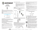
Unpackage the upright and base. Inspect both components to ensure no damage has occurred
during shipment (See Fig.5). Unpackage the provided bolts and lock nuts to be used for assembly.
Slide upright into base and align holes in each component. Insert stanchion bolts through the
assembly (See Fig. 6). Thread a lock nut onto the end of each stanchion bolt and tighten to ensure
secure t.
(2) Bolts
(2) Lock Nuts

User Manual
V1.0 2019 Copyright Safewaze Page 11
Fig. 7
Fig. 8
Insert threaded end of clamp assembly through the pre cut slot in base. Loosely thread the wing nut
onto the end of the clamp assembly (See Fig. 7).
Place entire assembly on top surface of I-Beam at desired installation location. Capture top of
I-Beam with the clamp assembly on one side, and the slotted portion of the base assembly on the
other side. Tighten the clamp assembly to the top of the I-Beam by rotating the wing nut in a
clockwise direction until secure (See Fig 8-A). When hand tight, strike the wing nut with a hammer or
further tighten with an adjustable wrench to ensure stanchion is secured to I-Beam. Tighten the
mounting bolts down onto top of I-Beam to secure the stanchion into place (See Fig 8-B). Install
Cotter Pin through end of Beam Clamp. Installed assembly should appear as indicated in
Fig. 9 (See Page 12).
A
B

User Manual
V1.0 2019 Copyright Safewaze Page 12
Fig. 9
Fig. 10
If stanchion is to be used as an intermediate post, the intermediate pass through bracket must be
installed. At the top of the upright, align the pre-drilled holes in the pass through bracket with the
pre-drilled holes in the stanchion (See Fig. 10). Insert the provied bolts through the holes and thread
the locking nuts onto the end of the bolts. Tighten until pass through bracket is secure to the top of
the upright.
Stanchion assembly
correctly installed on
top surface of I-Beam.

User Manual
V1.0 2019 Copyright Safewaze Page 13
Fig. 11
As the user reaches an intermediate stanchion, pass the snap hook under the rst side of the
intermediate bracket. When the snap hook is between both sides of the intermediate bracket, rotate
the snap hook to the other side of the Horizontal Lifeline, and pass the snap hook under the other
side of the intermediate bracket (See Fig 11). There is no need to disconnect the snap hook from the
Horizontal Lifeline.
Stanchion Components and Part Numbers
019-8038
Complete Assembly for
I-Beams 4” to 18”
020-8060
Complete Assembly for
I-Beams 4” to 12”
019-8046
Complete Assembly for
I-Beams 4” to 24”

User Manual
V1.0 2019 Copyright Safewaze Page 14
019-8040
I-Beam
Upright
019-8047
Base for I-Beams 4” to 18”
019-8041
Base for I-Beams 4” to 24”
019-8039
Upright Pass Through
Bracket
019-8045
I-Beam Clamp for I-Beams 4” to 18”
019-8042
I-Beam Clamp for I-Beams 4” to 24”
019-8043
I-Beam Clamp Wing Nut

User Manual
V1.0 2019 Copyright Safewaze Page 15
Beam Clamp Sizing Diagram
Specifications Table
XY
020-8060
X
Y≤ 2-1/4”
4” - 12”
019-8038
≤ 2-1/4”
4” - 18”
019-8046
≤ 2-1/4”
4” - 24”
Part #
Minimum
Tensile Strength
and Material
8,000 lbs.
Minimum Tensile
Strength
Refer to
SafeWaze HLL
Instruction Manuals
OSHA 1926.502
OSHA 1910.140
Stanchion Upright:
Steel
Stanchion Base:
Steel
Fasteners:
Grade 5
019-8038
I-Beams
4”-18” Width
020-8060
I-Beams
4”-12” Width
019-8046
I-Beams
4”-24” Width
Maximum User
Capacity
Standards and
Regulations I-Beam Stanchion

User Manual
V1.0 2019 Copyright Safewaze Page 16
Safewaze HLL
System Part Number Conguration A B
2 Person
Kernmantle HLL
019-8000
019-8001
019-8002
019-8003
1 Worker 2,800 lbs. 1,500 ft-lbs.
2 Workers 5,400 lbs. 3,000 ft-lbs.
4 Person
Double Braid Rope
HLL
019-8012
019-8013
019-8014
019-8015
1 Worker 3,400 lbs. 1,500 ft-lbs.
2 Workers 5,400 lbs. 3,000 ft-lbs.
2 Person
Cable HLL
019-8016
019-8017
019-8018
019-8019
1 Worker 5,400 lbs. 1,500 ft-lbs.
2 Workers 6,600 lbs. 3,000 ft-lbs.
4 Person
Cable HLL
FS-EX10000
FS-EX10500
1 Worker 2,000 lbs. 1,500 ft-lbs.
2 Workers 4,000 lbs. 3,000 ft-lbs.
A
B
Beam Load Requirments - End Anchor Stanchions

User Manual
V1.0 2019 Copyright Safewaze Page 17
Maintenance
Any Safewaze stanchion components requiring maintenance must be tagged
“unusable” and removed from service. Bolts and lock nuts can be replaced if
necessary by the user so long as equivalent to those provided during shipment.
Cleaning maintenance may be performed by the user.
Repairs to the product may only be made by the manufacturer or entities authorized in
writing by the manufacturer.
THIS SYSTEM MUST ONLY BE SERVICED BY A TRAINED AND COMPETENT INDIVIDUAL!
NEVER ATTEMPT TO SERVICE THIS UNIT OR TAMPER WITH ITS FUNCTION IN ANY WAY!
Storage
When not installed, the Safewaze stanchion should be stored in a cool, dry place out of
direct sunlight. Do not store in areas where damage from environmental factors such
as heat, light, excessive moisture, oil, chemicals and their vapors, or other degrading
elements may be present. Do not store damaged equipment or equipment in need of
maintenance in the same area as product approved for use. Equipment that has been
stored for an extended period must be inspected as described in these User
Instructions prior to use.
Inspection and Maintenance
Inspection
Inspect the stanchion for corrosion and/or damage.
Check the upright and base for signs of distortion or deformation.
Inspect stanchion assembly bolts and nuts prior to each use, and re-tighten as needed.
Inspect all components of HLL system per the manufacturer’s instrutions.
Frequency
All components of the Safewaze stanchion assembly must be inspected prior to each
use, and annually by a “competent person” (other than the user), as dened by OSHA.
Criteria
If inspection reveals any defect, inadequate maintenance, or unsafe condition, remove
from service until a “qualied person” as dened by OSHA 1926.32(m) can determine
the need for authorized repair or disposal.

User Manual
V1.0 2019 Copyright Safewaze
Inspection Log
DATE INSPECTED
BY:
CONDITION OF SYSTEM
Page 18

User Manual
V1.0 2019 Copyright Safewaze
Labels
Page 19
This product must be used in accordance with the manufacturers
instructions provided at shipment. For use only with approved SafeWaze
temporary Horizontal Lifeline (HLL) systems. Specifc information such as
fall clearances, number of users, span length, etc..., for approved HLL
systems are included in the individual HLL system instructions. User’s must
be trained in the use of this product and associated HLL systems. This
equipment must be installed and used under the supervision of a Qualified
Person. Failure to follow instructions, misuse, or alteration of this product
may result in serious injury or death. Use of this equipment near thermal,
electrical, chemical or other hazards should be avoided. Do not utiliize this
equipment if unsafe or hazardous conditions are present. Inspection results
should be recorded in the inspection log on this label, and the inspection
log located in the instruction manual.
DO NOT REMOVE THIS LABEL
Material: Steel
Meets OSHA 1926.502 and 1910.140 Requirements
www.safewaze.com
JAN FEB MAR APR MAY JUN JUL AUG SEP OCT NOV DEC
Model #:
019-8038 019-8040 019-8046
Date of Mfr.: XX/XXXX
Serial Number: XXXXXXX
Upright
Base
Mounting Bolt Clamp
019717
INSTALLATION
Tighten the clamp to the I-Beam using the supplied wing nut. After hand
tightening, strike the wing nut with a hammer, or continue tightening with an
adjustable wrench to ensure clamp is secure to I-Beam. Once complete,
tighten mounting bolts to top of I-Beam.
SafeLink 42" I-Beam Stanchion
WARNING
STANCHION
STANCHION

User Manual
V1.0 2019 Copyright Safewaze
WARRANTY
Safewaze
225 Wilshire Ave SW
Concord, NC 28025
PHONE: 1-800-230-0319
FAX: 1-704-262-9051
EMAIL: [email protected]
Web: safewaze.com
Page 20

Manual del usuario
220-00017 V1.0 2019 Copyright Safewaze
Cumple con las normas OSHA 1926.502 y 1910.140
El objetivo de este manual es cumplir las instrucciones del fabricante conforme a la
norma Z359 del Instituto Nacional Estadounidense de Normas (American National
Standards Institute, ANSI). Este manual debe formar parte de un programa de
capacitación de empleados conforme a la Ley de Salud y Seguridad Ocupacional
(Occupational Safety and Health Act, OSHA).
MONTANTE DE 42 PLG. PARA
LÍNEAS SALVAVIDAS HORIZONTALES

V1.0 2019 Copyright Safewaze Pág. 2
Índice de materias
1. ADVERTENCIAS GENERALES ........................................ 3
2. INTRODUCCIÓN Y USOS ................................................ 4
3. NORMAS DE SEGURIDAD APLICABLES ........................ 4
4. DENOMINACIONES DE USUARIOS ................................ 4
5. CONFIGURACIONES ESPECÍFICAS DEL PRODUCTO .. 5
6. LIMITACIONES ................................................................. 5
7. CONEXIONES ............................................................... 6-7
8. ESPECIFICACIONES .................................................... 7-8
9. INSTALACIÓN Y USO ................................................. 9-14
10. COMPONENTES DEL MONTANTE .......................... 13-14
11. DIMENSIONES Y ESPECIFICACIONES
DE LA ABRAZADERA DE VIGA EN I ............................. 15
12. REQUISITOS DE CARGA DE LA VIGA EN I .................. 16
13. INSPECCIÓN Y MANTENIMIENTO ................................ 17
14. REGISTRO DE INSPECCIONES .................................... 18
15. ETIQUETAS ................................................................... 19

V1.0 2019 Copyright Safewaze Pág. 3
ADVERTENCIA
Toda persona que use este equipo debe tener acceso a una copia de estas instrucciones. El usuario
debe leer y entender las instrucciones del fabricante para este y para todos los componentes de este
sistema integral de protección contra caídas. El usuario debe seguir estas instrucciones para usar,
inspeccionar y mantener correctamente el equipo. Estas instrucciones deben estar siempre a
disposición del usuario. Alterar este equipo o usarlo de manera incorrecta o no conforme a las
instrucciones del fabricante puede causar lesiones graves o muerte.
Este producto forma parte de un sistema integral de protección contra caídas. Este montante se
puede usar con cualquier Línea Salvavidas Horizontal (Horizontal Lifeline, HLL) de Safewaze u otros
sistemas de HLL a condición de que los requisitos de anclaje del sistema no superen las 4,000 lbs.
para satisfacer el factor de seguridad de 2 a 1 de este anclaje de 8,000 lbs. El usuario debe utilizar y
conectarse al sistema de HLL de Safewaze con un dispositivo restrictivo conforme a la norma ANSI
Z359 o un Sistema Personal de Parada de Caídas (Personal Fall Arrest System, PFAS). Este
producto no ha sido diseñado ni se debe usar como componente de sistema de posicionamiento,
suspensión o rescate. Los PFAS se componen generalmente de un Arnés de Cuerpo Entero (Full
Body Harness, FBH), un anclaje y un dispositivo de conexión. Los dispositivos de conexión a la línea
salvavidas de Safewaze son Cordones Absorbentes de Energía (Energy Absorbing Lanyards, EAL) o
Dispositivos Autorretráctiles (Self Retracting Devices, SRD). El FBH se conecta a la HLL de
Safewaze por el anillo dorsal en D.
Debe haber siempre un plan integral de protección contra caídas en los archivos de la empresa y a
disposición de todos los usuarios. El empleador y los usuarios de este equipo deben estar
debidamente capacitados para instalar, usar, inspeccionar y mantener este equipo.
Consulte al médico si duda de que su estado físico le permita absorber con seguridad el impacto de
una parada de caída. La edad y el estado físico afectan seriamente la capacidad de soportar caídas.
Ni los menores de edad ni las mujeres embarazadas deben usar este equipo. No respetar esta
advertencia puede causar lesiones graves o muerte.
De conformidad con el ANSI, la capacidad máxima de este equipo es de 310 lbs. (incluyendo
herramientas y equipo). Ciertos productos Safewaze mencionados en este manual pueden tener
capacidades máximas de más de 310 libras. Aunque ciertos componentes del PFAS en general
pueden tener más de 310 libras de capacidad, la instalación de un montante en el sistema de línea
de vida horizontal limita la capacidad a 310 libras por usuario.
Los usuarios de este equipo deben leer y entender todo este manual antes de usar el equipo.
Comuníquese con Safewaze si tiene preguntas sobre compatibilidades del equipo no consideradas
en este manual. No altere ni use incorrectamente este equipo. Algunos componentes de subsistema
pueden afectar el rendimiento y el funcionamiento de este equipo. No ancle este producto a
maquinaria en movimiento ni a estructuras que impliquen peligros químicos, eléctricos o gaseosos.
No respetar esta advertencia puede causar lesiones graves o muerte.

V1.0 2019 Copyright Safewaze Pág. 4
Introducción y usos
Gracias por comprar este montante de Safewaze para Líneas Salvavidas Horizontales (Horizontal
Lifelines, HLL). El usuario debe leer y entender todo este manual, que debe formar parte de un
programa de capacitación del usuario conforme a los requisitos de la OSHA y de las agencias
estatales correspondientes.
Este manual y todo otro material de enseñanza deben estar siempre a disposición del usuario del
equipo. El usuario debe entender cómo usar segura y efectivamente el montante de Safewaze y todo
el equipo de protección contra caídas que se use con el montante.
El montante de Safewaze ha sido diseñado teniendo en cuenta la seguridad del usuario. En sistemas
de HLL, estos montantes le ofrecen al usuario un punto de anclaje flexible que se puede montar y
desmontar fácilmente.
Normas y reglamentos de seguridad aplicables
NORMAS DEL ANSI
ANSI Z359.0
Definiciones y nomenclatura de parada de caídas y protección contra caídas
ANSI Z359.1
Requisitos de seguridad de sistemas personales de parada de caídas y sus subsistemas y componentes
ANSI Z359.2
Requisitos mínimos de programas integrales administrados de protección contra caídas
ANSI A10-14
Requisitos de seguridad de cinturones de seguridad, arneses, cordones y líneas salvavidas en
construcción y demolición
ANSI A10.32
Protección personal contra caídas en construcción y demolición
REGLAMENTOS DE LA OSHA
OSHA 1910.66
Sistemas personales de parada de caídas
OSHA 1926.502
Criterios y prácticas de los sistemas de protección contra caídas
Denominaciones de usuarios
Entienda las denominaciones de las personas que se exponen a
caídas o trabajan cerca de estructuras que implican riesgo de caída.
Persona calificada: Persona con certificación o título homologado y amplia experiencia o suficiente
prestigio profesional que se considera competente en la planificación y revisión de la conformidad de
los sistemas de rescate y protección contra caídas.
Persona competente: Persona altamente capacitada y experimentada que el empleador
responsabiliza de todos los elementos de un programa de seguridad contra caídas, tales como,
entre otros, regulación, administración y aplicación. Esta persona es competente en cuanto a la
identificación de peligros conocidos y predecibles, y está autorizada a suspender el trabajo para
eliminar los peligros.
Persona autorizada: Persona nombrada por el empleador para exponerse a riesgos de caídas
conocidos o posibles, o trabajar cerca de lugares en que existen tales riesgos.
Las personas calificadas o competentes son responsables de supervisar el lugar de trabajo y
garantizar que se cumplan las normas de seguridad.

V1.0 2019 Copyright Safewaze Pág. 5
Configuraciones específicas del producto
Parada de caída personal: En sistemas de HLL, los montantes de Safewaze forman parte de un
Sistema Personal de Parada de Caídas (Personal Fall Arrest System, PFAS). El sistema de HLL de
Safewaze con el cual se combine el montante determina el número máximo de usuarios. La
estructura a la cual se fija la línea salvavidas debe soportar una carga de 5,000 libras en todas las
direcciones permitidas por el sistema. La caída libre máxima permitida es de 6 pies. La longitud
máxima combinada del dispositivo de parada de caída, la extensión del cordón y el anillo en D es de
36 plg.
Limitaciones
Altura de caída: Debe haber suficiente espacio debajo del conector de anclaje para parar una caída
antes de que el usuario llegue al suelo o se golpee en una obstrucción. Cuando calcule la altura de
caída, considere la distancia de desaceleración, la estatura del usuario, la longitud del cordón o SRD,
un factor de seguridad de 2 pies como MÍNIMO, y todo otro factor aplicable (Figura 1).
Fig. 1
En todas las configuraciones, el intervalo de capacidad de este equipo es de 130 a
310 lbs. por usuario (incluyendo herramientas, ropa y equipo).
Diagrama de altura de caída
*** El diagrama que se muestra es SOLO un ejemplo de cálculo de altura de caída.
** EL USUARIO DEBE CONSULTAR LAS INSTRUCCIONES DE LA HLL PARA VER LAS ESPECIFICACIONES
CORRECTAS DE ALTURA DE CAÍDA **
Factor de seguridad
(2 pies)
Altura del anillo dorsal en D
del arnés desde los pies del
usuario
(6 pies)
Distancia de
desaceleración
(4 pies)
Distancia
requerida
desde el
anclaje
(18 pies en total)
Longitud del cordón
(6 pies)

V1.0 2019 Copyright Safewaze Pág. 6
A
Conexiones
Caídas pendulares: Antes de instalar o usar el sistema, elimine o minimice los riesgos de caídas pendulares,
que se producen cuando el punto de anclaje no está directamente encima del punto de caída. Trabaje siempre
lo más cerca posible del punto de anclaje. Las caídas pendulares aumentan significativamente la probabilidad
de lesiones graves o muerte (Figura 2).
Fig. 2
COMPATIBILIDAD DE CONEXIONES
Los conectores son compatibles con los elementos que se les conectan cuando han sido diseñados para
funcionar juntos de manera que su tamaño y su forma no causen la apertura imprevista de los mecanismos de
los cierres, independientemente de su orientación. Los conectores (ganchos, mosquetones y anillos en D)
deben tener al menos 5,000 lbs. (22.2 kN) de capacidad. Los conectores deben ser compatibles con el anclaje
y los otros componentes del sistema (Figura 4). No utilice equipos mutuamente incompatibles. Los conectores
incompatibles pueden desengancharse de improviso (Figura 3). Los conectores deben ser compatibles en
cuanto a tamaño, forma y capacidad. La norma ANSI Z359 y las directrices de la OSHA exigen ganchos de
presión y mosquetones de bloqueo automático. Comuníquese con Safewaze si tiene preguntas sobre
compatibilidad.
NOTA: ALGUNOS CONECTORES ESPECIALIZADOS TIENEN REQUISITOS
ADICIONALES. COMUNÍQUESE CON SAFEWAZE SI TIENE PREGUNTAS.
Fig. 3 - DESENGANCHE NO INTENCIONAL
Conectar un mosquetón o un gancho de presión a un conector demasiado pequeño o de forma irregular (1)
puede permitir que el conector abra el cierre del mosquetón o gancho de presión. Cuando se ejerce fuerza, el
cierre del mosquetón o del gancho presiona la pieza incompatible (2) y se abre (3). Esto permite que el
mosquetón o gancho de presión se desenganche (4).
2 - El cierre presiona
la pieza incompatible.
4 - Las piezas se desenganchan.
3 - El cierre se abre.
1 - Pieza incompatible

V1.0 2019 Copyright Safewaze Pág. 7
FORMACIÓN DE CONEXIONES
Los mosquetones y ganchos de presión de este equipo deben tener cierre de bloqueo doble y/o
cierre giratorio. Todas las conexiones deben ser compatibles en cuanto a tamaño, forma y
capacidad. No use equipo incompatible. Todos los conectores deben estar completamente cerrados
y bloqueados.
Los conectores Safewaze (mosquetones y ganchos de presión) deben usarse solo como se
especifica en las instrucciones de cada producto. En la Figura 4 hay ejemplos de conexiones
incorrectas. No conecte mosquetones o ganchos de presión…
A un anillo en D al cual ya esté conectado otro conector
De una manera que ejerza fuerza sobre el cierre (excepto en caso de ganchos de sujeción)
NOTA: Los ganchos de presión de gran apertura no se deben conectar a anillos en D de
tamaño estándar u objetos similares que se apoyarían en el cierre si el gancho o el anillo
en D se torciera o girara, a menos que el gancho de presión cumpla con la norma ANSI
Z359.12 y tenga un cierre de 3,600 lbs. (16 kN) de capacidad. Vea el marcado del
gancho de presión para verificar que sea compatible con la aplicación.
Con enganche falso, que se produce cuando las partes sobresalientes del mosquetón o gancho
de presión se enganchan en el ancla y, sin confirmación visual, dan la impresión de que el
mosquetón o gancho de presión está bien enganchado en el punto de anclaje
Uno a otro
Pasando la línea salvavidas de correa tejida alrededor del ancla y fijándola a la línea salvavidas,
excepto según lo permitido para los modelos de sujeción
A objetos cuya forma o tamaño pueda causar una desconexión o impedir que el mosquetón o
gancho de presión se cierre y se bloquee
De una manera que impida la alineación correcta del conector cargado.
Fig. 4 - CONEXIONES INCORRECTAS

V1.0 2019 Copyright Safewaze Pág. 8
Especificaciones
Se debe tener cuidado de evitar la maquinaria en movimiento y los peligros químicos o eléctricos
durante la instalación del montante. El contacto con tales peligros puede causar lesiones graves o
muerte.
Deben respetarse las capacidades de peso de los montantes y las HLL contenidas este manual para
evitar posibles fallas de sistema.
El montante y todo otro subsistema de PFAS asociado deben retirarse del servicio si se exponen a
fuerzas de parada de caída.
Comuníquese con Safewaze si va a utilizar este equipo de una manera o en una combinación no
específicamente definida en este manual.
Evite las superficies afiladas o abrasivas.
Evite los peligros eléctricos. Los destellos de arco de las operaciones de soldadura al arco y los
destellos de arco accidentales de equipos eléctricos pueden dañar el equipo y causar lesiones
graves o muerte.
No use nunca combinaciones de componentes o subsistemas que puedan afectar su funcionamiento
correcto o interferirse mutuamente.
Cada vez que se vaya a usar el equipo, se debe verificar lo siguiente:
El montante y el sistema de línea salvavidas horizontal de Safewaze y sus subsistemas no están
desgastados, dañados o deteriorados.
Todos los mosquetones y ganchos de presión se pueden cerrar y bloquear automáticamente.
Los cordones autorretráctiles funcionan correctamente. Jale la línea salvavidas levemente
primero y luego bruscamente para activar el mecanismo de bloqueo.
Ninguna cuerda o cable tiene rasgaduras, cortes, desgaste, abrasión, desprendimiento de
empalme, decoloración, corrosión, daño térmico, destrenzado, rebabas, torceduras u otras
señales de desgaste y daños.
Las terminaciones cosidas están firmes y enteras y no se ven dañadas.
Todos los empalmes de cuerda están firmes.
Todo sistema que se use con el montante de Safewaze está tensado conforme a las
instrucciones del sistema.
No hay indicadores de carga visibles.
Los componentes dañados, deteriorados y/o defectuosos que se han encontrado se han puesto
fuera de servicio inmediatamente conforme a las normas OSHA 29 CFR 1910.66 y 1926.502.
ADVERTENCIA: El montante de Safewaze NO ha sido diseñado como conexión de
punto único para un PFAS individual. No conecte nunca un PFAS individual
directamente al montante, ya que esto puede generar una carga incorrecta que
incapacite o dañe el montante. El montante de Safewaze para líneas salvavidas
temporales se puede usar con todos los sistemas de línea salvavidas horizontal de
Safewaze.

V1.0 2019 Copyright Safewaze Pág. 9
Instalación y uso
Antes de usar
Los usuarios de sistema personal de parada de caídas deben tener previsto un plan de rescate y los
medios de ponerlo en práctica en caso de que no puedan rescatarse a sí mismos.
El usuario debe leer y entender estas instrucciones y las instrucciones de cada componente y
subsistema del sistema personal de parada de caídas.
Las abrazaderas del montante de Safewaze vienen en 2 tamaños: de 4 a 18 plg. o de 4 a 24 plg. El
montante se fija en el ala superior de una viga en I. El ala puede tener un grosor máximo de 2-1/4
plg. Instalar dos montantes alineados en una viga en I establece una estructura de fijación o anclaje
de sistemas de línea salvavidas horizontal de Safewaze. Algunos sistemas de línea salvavidas
horizontal de Safewaze permiten instalar montantes intermedios en el tramo de la línea para dar
estabilidad y reducir la altura de caída requerida. Si se necesita un montante intermedio, el tope de
paso (pieza Nro. 019-8039) le permite al usuario pasar de un lado a otro del montante intermedio sin
desconectarse del sistema.
ADVERTENCIA: Si se va a usar una HLL de cuerda con un montante intermedio, se
debe prestar especial atención al inspeccionar la HLL. Los montantes intermedios en
sistemas de HLL de cuerda pueden aumentar el desgaste de la línea salvavidas. Se
requiere inspección adicional de las líneas salvavidas de cuerda en los puntos de
contacto con montantes intermedios.
Todos los componentes del montante deben ser inspeccionados antes de ser instalados y cada vez
que se vayan a usar. Durante la inspección previa al uso, todos los pernos de montaje y la tuerca de
mariposa se deben volver a apretar para garantizar la instalación del montante. Además, una
persona competente debe inspeccionar el montante una vez al año. Las inspecciones se pueden
registrar en la cuadrícula de inspección de la etiqueta del montante o en el registro de inspecciones,
página 17, de este manual.
Los montantes de línea salvavidas horizontal de Safewaze se deben instalar en vigas de acero
horizontales rectas y sin curvas. El montante da una altura de conexión de 42 plg. sobre el ala
superior de la viga.
Al instalar los montantes de Safewaze con líneas salvavidas horizontales de Safewaze, el usuario
debe prestar mucha atención a las instrucciones del sistema de línea salvavidas horizontal. Cada
sistema de línea salvavidas horizontal de Safewaze tiene características únicas en cuanto a número
máximo de usuarios, alturas de caída requeridas y flecha dinámica. Cada sistema de HLL de
Safewaze debe instalarse según el manual de instrucciones del fabricante del sistema.
Si hay varios usuarios conectados al sistema de HLL (consulte las instrucciones de la HLL en
cuestión para saber el máximo de usuarios permitido), cada usuario debe saber que si uno cae, los
otros pueden ser arrastrados hasta afuera de la superficie de trabajo cuando la línea salvavidas
descienda al parar la caída. Se recomienda que cada usuario tenga su propio sistema de HLL, o que
se establezcan tramos cortos para minimizar la posibilidad de que un usuario que cae arrastre a
otros.
En los manuales de instrucciones de los sistemas de HLL hay datos específicos tales como alturas
de caída, longitud máxima de tramo, máximo de usuarios, etc. La longitud máxima del tramo de línea
salvavidas horizontal con montante de Safewaze es de 60 pies. La longitud del tramo se puede
aumentar con montantes intermedios para formar varios tramos.

V1.0 2019 Copyright Safewaze Pág. 10
Desempaquete la columna y la base. Inspeccione los dos componentes para asegurarse de que no
se hayan dañado durante el transporte (Fig. 5). Desempaquete los pernos y tuercas de seguridad
suministrados. Monte la columna en la base y alinéeles los agujeros. Inserte los pernos a través de
los agujeros (Fig. 6). Póngale una tuerca de seguridad a cada perno y apriétela firmemente.
(2) pernos
(2) tuercas de
seguridad

V1.0 2019 Copyright Safewaze Pág. 11
Inserte el extremo roscado de la abrazadera a través de la ranura de la base. Póngale la tuerca de
mariposa a la abrazadera, pero no la apriete (Fig. 7).
Coloque la unidad entera sobre el ala superior de la viga en I en el punto en que desea instalar el
montante. Enganche el ala superior de la viga en I con la abrazadera en un lado y la parte ranurada
de la base en el otro. Apriete la abrazadera contra el ala superior de la viga en I girando la tuerca de
mariposa en sentido horario hasta que quede firme (Fig. 8-A). Cuando termine de apretar la tuerca
de mariposa a mano, dele con un martillo o apriétela aún más con una llave ajustable para
asegurarse de que el montante quede firme en la viga en I. Apriete los pernos de montaje contra el
ala superior de la viga en I para afirmar el montante en posición (Fig. 8-B). Instale el pasador de
chaveta a través del extremo de la abrazadera. La unidad instalada debe verse como se indica en la
Fig. 9 (página 12).

V1.0 2019 Copyright Safewaze Pág. 12
Si va a ser intermedio, al montante se le debe instalar un tope de paso intermedio. En la parte de
arriba del montante, alinee los orificios de fábrica del tope de paso con los orificios de fábrica del
montante (Fig. 10). Pase los pernos suministrados a través de los agujeros y póngales las tuercas de
seguridad. Apriételas hasta que el tope de paso quede firme en la parte de arriba del montante.
Montante instalado
correctamente sobre
el ala superior de
una viga en I.

V1.0 2019 Copyright Safewaze Pág. 13
Cuando llega al montante intermedio, el usuario debe pasar el gancho de presión por debajo del
lateral de entrada del tope de paso. Una vez que el gancho de presión queda entre los dos laterales
del tope de paso, el usuario debe girar el gancho de presión y pasarlo por debajo del lateral de salida
hasta el otro lado de la línea salvavidas horizontal (Fig. 11). No es necesario desconectar el gancho
de presión.
Componentes y números de pieza del montante
019-8038
Montante para viga en I
de 4 a 18 plg.
019-8046
Montante para viga en I
de 4 a 24 plg.
020-8060
Montante para viga en I
de 4 a 12 plg.

V1.0 2019 Copyright Safewaze Pág. 14
019-8045
Abrazadera de viga en I de 4 a 18 plg.
019-8039
Tope de paso de la
columna del montante
019-8040
Columna del montante
para viga en I
019-8042
Abrazadera de viga en I de 4 a 24 plg.
019-8047
Base para viga en I de 4 a 18 plg.
019-8041
Base para viga en I de 4 a 24 plg.
019-8043
Tuerca mariposa de abrazadera
de viga en I

V1.0 2019 Copyright Safewaze Pág. 15
Diagrama de dimensiones de la abrazadera de viga en I
Tabla de especificaciones
Pieza Nro.
Material y fuerza
de rotura mínima
Capacidad máxima
de usuarios
Normas y
reglamentos
Montante para
viga en I
020-8060
Para vigas en I
de 4 a 12 plg.
de ancho
8,000 libras de
fuerza de rotura
mínima
Columna del
montante: acero
Base del montante:
acero
Fijadores:
grado 5
Consulte el manual
de instrucciones de la
HLL correspondiente
de Safewaze
OSHA 1926.502
OSHA 1910.140
019-8038
Para vigas en I
de 4 a 18 plg.
de ancho
019-8046
Para vigas en I
de 4 a 24 plg.
de ancho
020-8060
019-8038
019-8046
X
4 a 12 plg.
4 a 18 plg.
4 a 24 plg.
Y
2-1/4 plg.
2-1/4 plg.
2-1/4 plg.

V1.0 2019 Copyright Safewaze Pág. 16
Requisitos de carga de la viga en I
Montantes de anclaje de extremo
Sistema de HLL de
Safewaze
Número de pieza
Configuración
A
B
HLL de Kernmantle
para 2 personas
019-8000
019-8001
019-8002
019-8003
1 usuario
2,800 lbs.
1,500 pies-lbs.
2 usuarios
5,400 lbs.
3.000 pies-lbs.
HLL de cuerda de
trenza doble para 4
personas
019-8012
019-8013
019-8014
019-8015
1 usuario
3,400 lbs.
1,500 pies-lbs.
2 usuarios
5,400 lbs.
3.000 pies-lbs.
HLL de cable para 2
personas
019-8016
019-8017
019-8018
019-8019
1 usuario
5,400 lbs.
1,500 pies-lbs.
2 usuarios
6.600 lbs.
3.000 pies-lbs.
HLL de cable para 4
personas
FS-EX10000
FS-EX10500
1 usuario
2,000 lbs.
1,500 pies-lbs.
2 usuarios
4,000 lbs.
3.000 pies-lbs.

V1.0 2019 Copyright Safewaze Pág. 17
Inspección y mantenimiento
Inspección
Inspeccione el montante para ver si está corroído o dañado.
Revise la columna y la base para ver si están distorsionadas o deformadas.
Inspeccione los pernos y tuercas del montante antes de usar el sistema y vuelva a apretarlos según
sea necesario.
Inspeccione todos los componentes del sistema de HLL conforme a las instrucciones del fabricante.
Frecuencia
Todos los componentes del montante de Safewaze deben ser inspeccionados cada vez que se van a
usar y una vez al año por una "persona competente" (que no sea el usuario) según la definición de la
OSHA.
Criterios
Si la inspección revela defectos, mantenimiento incorrecto o condiciones peligrosas, ponga el
sistema fuera de servicio hasta que una "persona calificada" según la definición de la
norma OSHA 1926.32 (m) pueda determinar si el sistema se puede reparar o se debe desechar.
Mantenimiento
A todo componente del montante de Safewaze que requiera mantenimiento se le debe poner una
etiqueta que diga "inutilizable", y el componente debe ser puesto fuera de servicio.
El usuario puede hacer el mantenimiento de limpieza.
Solo el fabricante o las entidades autorizadas por escrito por el fabricante pueden reparar el
producto.
SOLO SAFEWAZE O UNA PERSONA CAPACITADA Y COMPETENTE DEBE HACERLE SERVICIO A
ESTE SISTEMA. NUNCA INTENTE ALTERARLE LAS FUNCIONES O HACERLE SERVICIO.
Almacenamiento
Cuando no esté instalado, el montante de Safewaze debe estar guardado en un lugar fresco, seco y
protegido contra la luz directa del sol. No lo guarde en lugares donde pueda haber factores
ambientales perjudiciales tales como calor, luz, exceso de humedad, aceite, productos químicos y
sus vapores, u otros elementos degradantes. No guarde equipos dañados o que necesiten
mantenimiento en el mismo lugar que el producto aprobado para el uso. El equipo que ha estado
guardado durante un período prolongado debe ser inspeccionado como se describe en estas
instrucciones antes de usarlo.

V1.0 2019 Copyright Safewaze Pág. 18
Registro de inspecciones
FECHA
ESTADO DEL SISTEMA
INSPECCIONADO
POR:

V1.0 2019 Copyright Safewaze Pág. 19
Etiquetas
MONTANTE
MONTANTE
ADVERTENCIA
Este producto debe usarse conforme a las instrucciones que el fabricante le adjuntó al
momento de enviarlo. Este producto se debe usar solo con sistemas aprobados de Línea
Salvavidas Horizontal (Horizontal Lifeline, HLL) temporal de Safewaze. Los datos
específicos, tales como alturas de caída, número de usuarios, longitud de tramos, etc., de
los sistemas de HLL aprobados vienen en las instrucciones de cada sistema de HLL. Los
usuarios deben estar capacitados para usar este producto y los sistemas de HLL que se
van a usar con el producto. Este equipo debe instalarse y usarse bajo la supervisión de una
persona calificada. No seguir las instrucciones, usar el producto incorrectamente o alterarlo
puede causar lesiones graves o muerte. Evite usar este equipo cerca de peligros térmicos,
eléctricos, químicos, etc. No utilice este equipo en condiciones poco seguras o peligrosas.
Los resultados de las inspecciones deben registrarse en la cuadrícula de inspecciones de
esta etiqueta y en el registro de inspecciones del manual de instrucciones.
NO QUITE ESTA ETIQUETA.
INSTALACIÓN
Montante de 42 plg. para viga en I
Apriete la abrazadera en la viga en I con la tuerca de mariposa suministrada. Cuando
termine de apretar la tuerca de mariposa a mano, dele con un martillo o apriétela aún más
con una llave ajustable para asegurarse de que el montante quede firme en la viga en I.
Luego apriete los pernos de montaje contra el ala superior de la viga en I.
Columna
Perno de montaje
Abrazadera
Base
Modelo Nro. :
Fecha de fabricación: XX/XXX
Número de serie: XXXXXXX
Material: acero
Cumple con las normas OSHA 1926.502 y 1910.140
ENE. | FEB. | MAR. | ABR. | MAY. | JUN. | JUL. | AGO. | SEP. | OCT. | NOV. | DIC.

V1.0 2019 Copyright Safewaze Pág. 20
GARANTÍA
SAFEWAZE
225 Wilshire Ave SW
Concord, NC 28025
TELÉFONO: (800) 230-0319
FAX: 1-704-262-9051
CORREO ELECTRÓNICO: info@safewaze.com
Web: safewaze.com
-
 1
1
-
 2
2
-
 3
3
-
 4
4
-
 5
5
-
 6
6
-
 7
7
-
 8
8
-
 9
9
-
 10
10
-
 11
11
-
 12
12
-
 13
13
-
 14
14
-
 15
15
-
 16
16
-
 17
17
-
 18
18
-
 19
19
-
 20
20
-
 21
21
-
 22
22
-
 23
23
-
 24
24
-
 25
25
-
 26
26
-
 27
27
-
 28
28
-
 29
29
-
 30
30
-
 31
31
-
 32
32
-
 33
33
-
 34
34
-
 35
35
-
 36
36
-
 37
37
-
 38
38
-
 39
39
-
 40
40


SafeWaze 019-8038 El manual del propietario
- Tipo
- El manual del propietario
en otros idiomas
- English: SafeWaze 019-8038 Owner's manual
Artículos relacionados
-
 SafeWaze 019-8016 El manual del propietario
-
 SafeWaze 019-11000 El manual del propietario
-
 SafeWaze 019-8008 El manual del propietario
-
 SafeWaze 019-8014 El manual del propietario
-
 SafeWaze 019-11004 El manual del propietario
-
 SafeWaze 019-4007 El manual del propietario
-
 SafeWaze 019-11001 El manual del propietario
-
 SafeWaze 019-11003 El manual del propietario
-
 SafeWaze FS-EX310-1 El manual del propietario
-
 SafeWaze 018-4000 El manual del propietario


