Mongoose 6061 El manual del propietario
- Categoría
- Bicicletas
- Tipo
- El manual del propietario
Este manual también es adecuado para

MOUNTAIN BICYCLE OWNER'S MANUAL
THIS MANUAL CONTAINS IMPORTANT SAFETY, PERFORMANCE AND MAINTENANCE
INFORMATION. READ THE MANUAL BEFORE TAKING YOUR FIRST RIDE ON YOUR
NEW BICYCLE, AND KEEP THE MANUAL HANDY FOR FUTURE REFERENCE.


Contents
1 Safety ............................................4
Safety Signal Words ...............................4
User Responsibility................................4
Bicycle Setup ....................................5
Personal Safety...................................8
Riding Safety....................................11
Before You Ride Safety Checklist ...................13
2 Parts Idencaon . . . . . . . . . . . . . . . . . . . . . . . . . . . . . . . . 14
3 Assembly . . . . . . . . . . . . . . . . . . . . . . . . . . . . . . . . . . . . . . . . 16
Tools Required . . . . . . . . . . . . . . . . . . . . . . . . . . . . . . . . . . 16
GengStarted..................................17
AachtheHandlebar.............................18
AachtheLockonGrips . . . . . . . . . . . . . . . . . . . . . . . . . . 20
AachtheBrakeCables . . . . . . . . . . . . . . . . . . . . . . . . . . 21
AachtheFrontWheel ...........................22
AachtheSeat..................................25
AachthePedals ................................28
4 Adjustments......................................29
Tools Required . . . . . . . . . . . . . . . . . . . . . . . . . . . . . . . . . . 29
AdjusngtheBrakes . . . . . . . . . . . . . . . . . . . . . . . . . . . . . 30
AdjusngtheDerailleur...........................40
AdjusngtheSeatHeight . . . . . . . . . . . . . . . . . . . . . . . . . 42
AdjusngtheHandlebar . . . . . . . . . . . . . . . . . . . . . . . . . . 44
AdjusngtheHeadset ............................46
AdjusttheBoomBracket . . . . . . . . . . . . . . . . . . . . . . . . 50
5 Use..............................................52
BrakeOperaon.................................52
GearOperaon..................................53
Security ........................................55
6 Maintenance . . . . . . . . . . . . . . . . . . . . . . . . . . . . . . . . . . . . . 56
Basic Maintenance ...............................56
LubricaonSchedule .............................57
Parts Maintenance . . . . . . . . . . . . . . . . . . . . . . . . . . . . . . 58
HubBearings....................................61
InangtheTireTube . . . . . . . . . . . . . . . . . . . . . . . . . . . . 61
RepairingaFlatTire ..............................62
TroubleshoongGuide ...........................63
7 Warranty.........................................66
Purchase Record.................................67

2
Congratulaons
onyournewbicycle!Properassemblyandoperaonofyour
bicycleisimportantforyoursafetyandenjoyment.Our
customerservicedepartmentisdedicatedtoyoursasfacon
withPacicCycleanditsproducts.Ifyouhavequesonsorneed
adviceregardingassembly,parts,performance,orreturns,
pleasecontacttheexpertsatPacicCycle.Enjoy the ride!
Toll free: 1-800-626-2811.
Customer Service hours:Monday-Friday8AM-5PMCentral
StandardTime(CST)
Youmayalsoreachusat:
Web:www.pacic-cycle.com
Email:customerservice@pacic-cycle.com
Mail: P. O. Box 344
4730E.RadioTowerLane
Olney,IL62450
Do not return this item to the store. Please call Pacic Cycle
customer service if you need assistance. You will need your
modelnumberanddatecodelocatedontheservicesckernear
theboombracketarea.SeeSecon 7: Purchase Record for the
locaonofthemodelnumberonyourbicycle.
About This Manual
Itisimportantforyoutounderstandyournewbicycle.
Byreadingthismanualbeforeyougooutonyourrstride,you’ll
knowhowtogetbeerperformance,comfort,andenjoyment
fromyournewbicycle.Itisalsoimportantthatyourrstrideon
yournewbicycleistakeninacontrolledenvironment,awayfrom
cars,obstaclesandothercyclists.
Thismanualcontainsimportantinformaonregardingsafety,
assembly,use,andmaintenanceofthebicyclebutisnot
intendedtobeacompleteorcomprehensivemanualcoveringall
aspectsconcerningbicycleownership.Werecommend
consulngabicyclespecialistifyouhaveanydoubtsorconcerns
regardingyourexperienceorabilitytoproperlyassembleand
maintainthebicycle.
A Special Note For Parents and Guardians
Itisatragicfactthatmostbicycleaccidentsinvolvechildren.
Asaparentorguardian,youbeartheresponsibilityforthe
acviesandsafetyofyourminorchild.Amongthese
responsibiliesaretomakesurethatthebicyclewhichyour
childisridingisproperlyedtothechild;thatitisingood
repairandsafeoperangcondion;thatyouandyourchild
havelearned,understandandobeynotonlytheapplicablelocal
motorvehicle,bicycle,andtraclaws,butalsothecommon
senserulesofsafeandresponsiblebicycling.Asaparent,you
shouldreadthismanualbeforelengyourchildridethe
bicycle.Pleasemakesurethatyourchildalwayswearsan
approvedbicyclehelmetwhenriding.

3
CorrectFing
Makesureyourhelmetcoversyourforehead
IncorrectFing
Foreheadisexposedandvulnerabletoseriousinjury
• ALWAYS WEAR A PROPERLY FITTED
HELMET WHEN RIDING YOUR BICYCLE
• DO NOT RIDE AT NIGHT
• AVOID RIDING IN WET CONDITIONS
Helmets
Save
Lives!

4
1 Safety
WARNING!
CAUTION!
SAFETY SIGNAL WORDS
The following safety signal words indicate a safety message.
The symbol alerts you to potenal hazards. Failure to follow the
warning may result in damage to property, injury, or death.
This manual contains many Warnings and Cauons concerning
the consequences of failure to follow safety warnings. Because
any fall can result in serious injury or even death, we do not
repeat the warning of possible injury or death whenever the risk
of falling is menoned.
Indicates a hazard or unsafe pracce that will result in severe
injury or death. Failure to read, understand and follow the safety
informaon in this manual may result in serious injury or death.
Indicates a hazard or unsafe pracce that could result in
minor injury.
Indicates a hazard unrelated to personal injury, such as
property damage.
❶ Safety
NOTICE
USER RESPONSIBILITY
All persons assembling, using, and maintaining the bicycle must
read and understand the safety warnings and operang
instrucons in this manual before using the bicycle.
It is the responsibility of the user, or in the case of a child rider,
an adult, to ensure the bicycle is properly maintained and in
proper operang condion. Doing so will reduce the risk of
injury. Always conduct regular maintenance and inspecon of
your bicycle. Complete the Safety Checklist at the end of this
secon before each use.
A responsible adult must always supervise the use of the bicycle
by a child. You must ensure:
WARNING!
• The child is wearing the proper protecve are and approved
bicycle helmet.
• The child is seated securely and the bicycle is properly ed
to the child.
• The child understands applicable laws and common sense
rules of safe responsible bicycling.
Do not install any kind of power plant or internal combuson
engine to a bicycle. Adapng a bicycle in this manner poses an
extreme safety risk to rider and could result in loss of control
or death.

Safety 1
5
Figure 1.1
BICYCLE SETUP
Correct Bicycle Size
Riding a bicycle that is not correctly sized to the rider may result
in the rider’s feet not being able to touch the ground and
balance the bicycle, properly reach the handlebar for steering or
braking, and loss of control when pedaling.
Use the wheel size in the following table as a guide to match the
rider and bicycle. For example, bicycles with a wheel size of 12
inches t a rider that is 28 to 38 inches tall. Note: Some bicycles
such as folding bicycles may have smaller wheels but sll t
adults.
If the bicycle has a top tube on the frame, check that there is
one to three inches of clearance between the rider and the top
tube. Figure 1.1
Inability to safely reach the handlebars and dismount the
bicycle may result in loss of control of the bicycle. If the
bicycle has a top tube on the frame, ensure there is one to
three inches of clearance between the rider and the top tube.
Improper setup or maintenance of the bicycle may result in
an unexpected movement, loss of control, and serious injury
or death.
WARNING!
Wheel Size Riders Approximate Height
12 inch 28 - 38 inches tall
16 inch 38 - 48 inches tall
18 inch 42 - 52 inches tall
20 inch 48 - 60 inches tall
24 inch 56 - 66 inches tall
26 inch, 27.5 inch,
29 inch, 700c
64 - 74 inches tall
1 to 3 inch
clearance
Top tube

6
1 Safety
Figure 1.2
Improperly adjusted seat height could aect the rider’s ability
to reach the handlebar and pedals may result in an unexpected
movement, loss of control, and serious injury or death. Follow
these guidelines when adjusng the seat height. Always
ensure the seat post minimum inseron marks are below the
seat clamp and cannot be seen. Ensure the seat clamp is
locked and the seat cannot move.
WARNING!
Seat Height and Handlebar Reach
❶ Your legs should be almost completely straight when the
pedal is in the down most posion, just a slight bend in
the knee. Figure 1.2
Note: The rider’s feet may not touch the ground easily. If
this is the case the rider can simply move forward o the
seat to mount and dismount the bicycle or the seat can be
adjusted lower if the rider is uncomfortable with the height,
but note that riding is more dicult with the seat too low,
as the legs are in an unnatural posion.
Do not raise the seat so much the knees lock straight when
pedaling or you have to move forward o the seat to pedal.
This is unsafe and the bicycle cannot be controlled in this
condion.
❷ You should be able to safely reach the handlebar with
your arms bent slightly (approximately 10 degrees) at
the elbow.
Adjust the seat
height
1
2

Safety 1
7
Figure 1.3
Wheels
❶ Some bicycles will come equipped with quick-release levers
for the front wheel. The wheels must be securely locked.
Ensure the wheel quick-release lever is rmly locked in
place. Figure 1.3
Seat Post
❷ Ensure the seat post’s minimum inseron marks are not
visible above the quick-release seat clamp and the clamp is
locked in place.
Note: See Secon 4: Adjusng the Seat Height if
adjustments are needed.
Improper setup or maintenance of the quick-release levers
may result in an unexpected movement, loss of control, and
serious injury or death. Before riding always check that the
quick-release lever is rmly locked in place and the seat does
not move.
Quick-release Levers
WARNING!
1
Quick-release
seat clamp
Quick-release
wheel
2
Minimum inseron
marks are located on
the seat post
Seat post
Seat tube

8
1 Safety
Riding a bicycle without protecve gear, clothing, or a helmet
may result in serious injury or death. Always wear protecve
gear, clothing, and helmet when riding the bicycle. Ensure
protecve gear does not interfere with steering, braking, and
pedaling.
WARNING!
ProtecveGearandClothing
Always wear: Figure 1.4
• Colors that are easily seen and, if possible, reecve clothing.
• Clothing appropriate for the weather condions.
• Use of protecve gear such as pads for the knees and elbows
is highly recommended for children.
• A properly ed, ASTM or SNELL approved, bicycle helmet
shall be worn at all mes by riders of the bicycle. For
informaon regarding how to properly t a helmet visit:
hp://www.nhtsa.gov/people/injury/pedbimot/bike/
easystepsweb
Do not wear:
• Loose clothing parts, strings, or jewelry that may become
entangled with moving parts on the bicycle or interfere with
handling of the bicycle.
• Pants with loose pant legs. If necessary, always tuck pant legs
into a sock or use a leg band to avoid the clothing becoming
caught in the drive chain.
• Shoes with uned shoe laces.
PERSONAL SAFETY
Figure 1.4
Properly ed helmet
Elbow pads
Knee pads
Leg band
Shoes fastened
or ed
Easily seen or
reecve clothing

Safety 1
9
Figure 1.6
Figure 1.5
Helmet Use
Important! Many states have passed helmet laws regarding
children. Make sure you know your state’s helmet laws. It is your
job to enforce these rules with your children. Even if your state
does not have a children’s helmet law, it is recommended that
everyone wear a helmet when cycling. When riding with a child
carrier seat or trailer, children must wear a helmet.
It is strongly advised that a properly ng, ASTM or SNELL
approved, bicycle safety helmet be worn at all mes when riding
your bicycle. In addion, if you are carrying a passenger in a
child safety seat, they must also be wearing a helmet.
The correct helmet should: Figure 1.5
• Be comfortable
• Have good venlaon
• Fit correctly
• Cover forehead
Incorrecthelmetposion:Figure1.6
• Helmet does not cover the forehead

10
1 Safety
Figure 1.7
Missing, damaged, or dirty reectors will aect the ability of
others to see and recognize you as a moving bicyclist, increasing
the risk of being hit, serious injury or death. Always check the
reectors are in place and make sure they are clean, straight,
unbroken and securely mounted before riding the bicycle.
WARNING!
Important! Federal regulaons require every bicycle over 16
inches to be equipped with front, rear, wheel, and pedal
reectors. Many states require specic safety devices. It is your
responsibility to familiarize yourself with the laws of the state
where you ride and to comply with all applicable laws, including
properly equipping yourself and your bike as the law requires.
Bicycles under 16 inches are considered “sidewalk bicycles” and
may not be ed with reectors. These bicycles should not be
ridden on streets, at night or unsupervised by an adult.
Check and conrm the front and rear reectors are in the
correct posion: Figure 1.7
• FrontReector: Should aim forward (when viewed from
above) and be mounted so it is within 5 degrees of vercal.
• RearReector: Should aim straight back (when viewed from
above) and be mounted so it is within 5 degrees of vercal.
Reectors
Rear (red)
plus or minus
5 degrees of
vercal
Front wheel
(white)
Rear wheel
(white)
Pedal (orange)
Front (white)

Safety 1
11
WARNING!
General Safety
• Familiarize yourself with all the bicycle’s features before
riding. Pracce gear shis, braking, and the use of toe clips
and straps, if installed.
• Always ride defensively in a predictable, straight line. Never
ride against trac.
• Expect the unexpected (e.g., opening car doors or cars
backing out of concealed driveways).
• Take extra care at intersecons and when preparing to pass
other vehicles.
• Maintain a comfortable stopping distance from all other
riders, vehicles and objects. Safe braking distances and forces
are subject to the prevailing weather condions. Do not lock
up the brakes. When braking, always apply the rear brake
rst, then the front. The front brake is more powerful and if it
is not correctly applied, you may lose control and fall.
• Always use the correct hand signals to indicate turning
or stopping.
• Obey the trac laws (e.g., stopping at a red light or stop sign,
giving way to pedestrians).
• Wear proper riding are, reecve if possible, and avoid
open toe shoes.
• Do not use items that may restrict your hearing and vision.
• Do not carry packages or passengers that will interfere with
your visibility or control of the bicycle.
RoadCondions
• Be aware of road condions. Concentrate on the path ahead.
Avoid pot holes, gravel, wet road markings, oil, curbs, speed
bumps, drain grates and other obstacles.
• Cross train tracks at a 90 degree angle or walk your
bicycle across.
Wet Weather
• When riding in wet weather always wear reecve clothing
and use safety lights to enhance visibility.
• Exercise extreme cauon when riding in wet condions.
• Ride at a slower speed. Turn corners gradually and avoid
sudden braking.
• Brake earlier, it will take a longer distance to stop.
• Pot holes and slippery surfaces such as line markings and train
tracks all become more hazardous when wet.
RIDING SAFETY
Riding the bicycle in unsafe condions (i.e. at night), in an unsafe
manner, or disregarding trac laws may result in an unexpected
movement, loss of control, and serious injury or death.

12
1 Safety
Night Riding
• Important! Riding a bicycle at night is not recommended.
Check your local laws regarding night riding.
• Ensure bicycle is equipped with a full set of correctly
posioned and clean reectors.
• Use a white light on the front and a red light on the rear.
Use lights with ashing capability for enhanced visibility.
• If using baery powered lights, make sure baeries are
well charged.
• Wear reecve and light colored clothing. Wear reecve
clothing and use safety lights for increased visibility.
• Ride at night only if necessary. Slow down and use familiar
roads with street lighng.
Hill Technique
• Gear down before a climb and connue gearing down as
required to maintain pedaling speed.
• If you reach the lowest gear and are struggling, stand up on
your pedals. You will then obtain more power from each
pedal revoluon.
• On the descent, use the high gears to avoid rapid pedaling.
• Do not exceed a comfortable speed; maintain control and
take addional care.
• Braking will require addional distance. Iniate braking slowly
and earlier than usual.
Cornering Technique
• Brake slightly before cornering and prepare to lean your body
into the corner.
• Maintain the inside pedal at the 12 o’clock posion and
slightly point the inside knee in the direcon you are turning.
• Keep the other leg straight, do not pedal through fast or ght
corners.
• Decrease your riding speed, avoid sudden braking and
sharp turns.
Safe Riding Rules for Children
• Many states require that children wear a helmet while cycling.
Always wear a properly ed helmet.
• Do not play in driveways or the road.
• Do not ride on busy streets.
• Do not ride at night.
• Obey all the trac laws, especially stop signs and red lights.
• Be aware of other road vehicles behind and nearby.
• Before entering a street: Stop, look le, right, and le again
for trac. If there’s no trac, proceed into the roadway.
• If riding downhill, be extra careful. Slow down using the
brakes and maintain control of the steering.
• Never take your hands o the handlebars, or your feet o the
pedals when riding downhill.

Safety 1
13
BEFORE YOU RIDE SAFETY CHECKLIST
Before every ride, it is important to carry out the following
safety checks. Do not ride a bicycle that is not in proper
workingcondion!
Accessories
□ The reectors are properly placed and not obscured. Note:
Bicycles 16” and under may not be equipped with reectors
since small children should not ride at night.
□ All other ngs on the bike are properly and securely
fastened, and funconing.
□ The rider is wearing a properly ed helmet (protecve gear
if necessary) and that clothing and loose items are properly
constrained.
Bearings
□ All bearings are lubricated, run freely and display no excess
movement, grinding or raling.
Brakes
□ The front and rear brakes work properly.
□ The brake shoe pads are not overly worn and are correctly
posioned in relaon to the rims.
□ The brake control cables are lubricated, correctly adjusted
and display no obvious wear.
□ The brake control levers are lubricated and ghtly secured
to the handlebar.
Chain
□ The chain is oiled, clean and runs smoothly.
Cranks and Pedals
□ The pedals are securely ghtened to the crank arms.
□ The crank arms are secured to the axle and are not bent.
Frame and Fork
□ The frame and fork are not bent or broken.
□ The quick-release clamps are locked in place.
Steering
□ The handlebar and post are correctly adjusted and
ghtened, and allow proper steering.
□ The handlebars are set correctly in relaon to the forks and
the direcon of travel.
□ The handlebar binder bolt is ghtened.
Wheels and Tires
□ The rims do not have dirt or grease on them.
□ The wheels are properly aached to the bicycle and axle.
□ The res are properly inated within the recommended
pressures displayed on the res sidewall.
□ The res have the proper amount of tread, no bulges or
excessive wear.

14
Part name
Torque
(in-lb)
13 Valve stem -
14 Spoke -
15 Fork dropout -
16 Wheel axle nut (front) 180-240
16A Wheel quick-release (opon) -
16B Wheel axle nut (rear) 240-300
17 Front fork -
18 Crank arm (1-piece) 300
18A Crank arm (3-piece) 390
19 Chainwheel -
20 Boom bracket lockring 300
21 Pedal 300-360
22 Front derailleur -
23 Chain -
24 Chain stay -
Mountain Bicycle
Get to know the parts of your bicycle. This will help with assembly, maintenance, and troubleshoong. Models vary in color and style.
Part name
Torque
(in-lb)
1 Handle grip -
2 Rear brake lever 55 - 70
3 Brake cable -
4 Handlebar -
5 Stem binder bolt 100-120
6 Handlebar binder bolt(s) 145-200
7 Stem -
8 Headset 175-260
9 Caliper brake assembly 50 - 70
9A Brake cable pinch bolt 50 - 70
9B Brake pads -
9C Brake pads hardware 50 - 60
10 Caliper brake aaching nut 70-85
11 Tire -
12 Rim -
Part name
Torque
(in-lb)
25 Rear derailleur -
26 Freewheel -
27 Linear brake assembly -
28A Brake cable pinch bolt 50-70
28B Brake pad -
28C Brake pad hardware 50-60
28D Brake spring -
28E Brake pivot bolt 17-20
29 Saddle (seat) -
30 Seat post aaching hardware 130-170
31 Seat post -
32 Seat post quick-release 60-80
32A Seat post bolted clamp (opt.) -
❷ Parts Idencaon

Parts Idencaon 2
15
2
1
4
3
9
8
11
17
15
26
2124
14
23
28B
27
5
12
13
6
25
7
28C
30
10
16
16B
19
28A
28D
28E
29
18, 18A
20
31
32
22
16A
32A
9A
9C
9B

3 Assembly
16
Figure 3.1
If you need replacement parts or have quesons pertaining to
the assembly of your bicycle, call the service line direct at:
1-800-626-2811. Monday - Friday 8:00 am to 5:00 pm Central
Standard Time (CST).
TOOLS REQUIRED
• Phillips head screw driver
• 2.5 mm, 4 mm, 5 mm, 6 mm and 8 mm Allen wrench
• Adjustable wrench or a 9 mm, 10 mm, 14 mm and 15 mm
open and box end wrenches
• A pair of pliers with cable cung ability
Your new bicycle was assembled and tuned in the factory and
then parally disassembled for shipping. You may have
purchased the bicycle already fully assembled and ready to ride
or in the shipping carton in the parally disassembled form.
The following instrucons will enable you to prepare your
bicycle for years of enjoyable cycling.
For more details on inspecon, lubricaon, maintenance and
adjustment of any area please refer to the relevant secons in
this manual. If you have quesons about your ability to
properly assemble this unit, please consult a qualied specialist
before riding.
❸ Assembly
WARNING!
• Improper assembly of this product may result in serious
injury or death. Always follow the instrucons in this
manual and check crical components (e.g. wheels, seat,
pedals, brakes, derailleurs, res) before each use.
• We recommend that you consult a bicycle specialist if you
have doubts or concerns as to your experience or ability to
properly assemble, repair, or maintain your bicycle. If your
bicycle was obtained assembled, we recommend that you
read these instrucons and perform checks specied in
this manual before riding.

Assembly 3
17
17
Figure 3.2
GETTING STARTED
❶ Open the carton from the top and remove the bicycle.
Figure 3.2
❷ Remove the straps and protecve packaging from the
bicycle. Important! Do not discard packing materials unl
assembly is complete to ensure that no required parts are
accidentally discarded.
❸ Inspect the bicycle and all accessories and parts for possible
shortages. It is recommended that the threads and all moving
parts in the parts package be lubricated prior to installaon.
Note: We recommend using a lithium based grease on the
parts before assembly.
Pedals
Handlebar
assembly
Frame
Front wheel
Seat
Seat post

3 Assembly
18
Figure 3.3
Figure 3.4
There are two types of stems that aach the handlebar to the
steerer tube. It is either a quill or clamp (threadless) stem.
AachingaQuillStem
❶ Turn the front fork to face forward. Figure 3.3
Posion the handlebar assembly over the steerer tube.
Look at all the cables to be sure they run in a smooth arc
from the shier or brake lever to the front brake or cable
stop on the frame. Important! If they are twisted or kinked,
the shiing and braking will not work. Figure 3.4
❷ Insert the stem post into the steerer tube and adjust the
handlebar height unl the rider feels they have control of
the bicycle and are comfortable. See Secon 1, Fig. 1.2:
Seat Height and Handlebar Reach for guidelines.
WARNING!
• Improper aachment of the handlebar may result in
damage to the stem post, steerer tube and result in loss of
control, serious injury or death. Ensure the minimum
inseron marks on the stem post are not visible above the
top of the headset.
• Failure to properly ghten handlebar components may
result in loss of control, serious injury or death.
Always check the handlebar cannot move and is secured to
the frame before riding the bicycle.
ATTACH THE HANDLEBAR Important! Be sure the minimum inseron marks do not go
above the top of the headset and are not visible.
❸ Using a 6 mm Allen wrench ghten the stem binder bolt at
the top of the stem post. Check the handlebar binder bolt(s)
to be sure they are properly ghtened and the handlebar is
clamped in place. Note: See Secon 4: Adjusng the
Handlebar if adjustments are needed.
Front fork
faces forward
Minimum
inseron
marks
Handlebar binder bolt(s)
Headset
Stem post
Steerer tube
Stem
b i n d e r
bolt
1
2
3

Assembly 3
19
19
Figure 3.6
Figure 3.5
AachingaThreadlessStem
Important! Do not disassemble the headset or lose any parts.
Be sure the end of the fork is on the ground or being held with
your free hand, because once you loosen the top cap the fork
assembly may fall out of the frame.
❶ Turn the front fork to face forward (ie: the fork dropout is in
the furthest forward posion). Figure 3.3
❷ Using a 5 mm Allen wrench loosen the top cap bolt on the
steerer tube and remove the top cap and bolt. Important!
Do not remove the spacers. Figure 3.5
❸ Posion the handlebar assembly over the steerer tube. Look
at all the cables to be sure they run in a smooth arc from the
shier or brake lever to the front brake or cable stop on the
frame. Important! If they are twisted or kinked, the shiing
and braking will not work.
❹ While holding the fork assembly in place, use a 6 mm Allen
wrench and loosen the stem pinch bolts. Slide the handlebar
assembly onto the steerer tube.
❺ Align and center the stem to the fork and wheel. Tighten the
stem pinch bolts unl there is no play between the stem and
stem tube. Note: There should be a 3 to 5 mm (1/8" - 3/16")
gap between the top of the stem and stem post. Figure 3.6
❻ Place the top cap onto the top of the steerer tube. Insert
and tighten the top cap bolt until it is snug. Do not over
tighten.
❼ Using a 5 mm Allen wrench ghten the top cap bolt. Do the
following checks to determine if the headset is properly set.
Tighten or loosen the top cap bolt if necessary.
• Li up the front wheel of the bicycle, if the wheel does
not move freely le to right the headset is too ght.
• Hold the handlebar, close the brakes and rock the fork
back and forth. If you hear a knock or clunking sound the
headset is too loose.
Note: If needed, see Secon 4: Adjusng the Headset for
more detailed informaon. See Secon 4: Adjusng the
Handlebar for informaon on aligning the handlebar.
Top cap
and bolt
Stem pinch
bolts
Headset
Steerer tube
Stem
Spacers
1/8" - 3/16"
(3 - 5 mm)
2
4
5
3

3 Assembly
20
Figure 3.7
ATTACH THE LOCKON GRIPS
Follow these steps if your bicycle is equipped with lockon grips.
❶Clean the handlebar surface.
❷ Slide the lockon grip over the handlebar as far as it can go.
Note: Rotate the clamp so the clamp screws are on the
underside of the handlebar. Figure 3.7
❸ Adjust the grip to how you want it to feel.
❹ Using a 2.5 mm Allen wrench ghten the clamps on both
ends of the lockon grip. Check the grip is securely aached
and does not rotate or slip.
❺Snap the lockon grip cap onto the end of the lockon grip.
❻Repeat steps 1 - 5 for the second lockon grip.
Lockon grips
Lockon grip cap
4
2
5

Assembly 3
21
21
Figure 3.8
Figure 3.9
Figure 3.10
There are four brake opons, Caliper, Linear Pull, Disc and
Hydraulic Disc. If you have hydraulic disc brakes, see the manual
on hydraulic disc brakes that came with your bicycle.
Follow these steps if the brake cables are not aached to the
brake levers:
❶ Rotate the cable adjustment barrel and cable nut unl the
slots are aligned with the slot on the brake lever body.
Figure 3.8
❷ Press the brake lever towards the grip.
❸ Slide the brake cable through the slots and place the cable
head into the brake lever. Figure 3.9
❹ Release the brake lever. Figure 3.10
❺ Lightly pull on the cable and rotate the cable nut and cable
barrel so they are no longer aligned.
Note: See Secon 4: Adjusng the Brakes if adjustments are
needed.
Failure to properly set the brakes may result in the inability to
stop the bicycle movement and cause serious injury or death.
Be sure the brakes are funconing properly before using the
bicycle.
ATTACH THE BRAKE CABLES
WARNING!
Cable adjustment
barrel slot
Cable nut slot
Brake cable slot
Brake lever
Cable head
Brake cable
4
2
5
3
1

3 Assembly
22
Figure 3.12
Figure 3.11
ATTACH THE FRONT WHEEL
There are two types of front wheel assemblies; nued and
quick-release. Note: Quick-release wheels may be on both the
front and rear wheels or just one. Also, some re tread paerns
have a direcon, so compare your front re and rear re of the
bicycle so that both tread paerns face the same way.
NuedFrontWheel
❶Posion the front wheel between the front fork legs with
the axle resng inside the fork drop outs. Note: If the front
wheel has a disc brake insert the disc rotor into the slot on
the caliper body as you insert the wheel axle into the fork
drop out. Important! Be sure the wheel is as centered as
possible between the fork legs. Figure 3.11
❷ Place the axle washers on the axle and slide it up against the
fork drop out.
❸ Aach the two axle nuts on the axle. Tighten one nut part
way, then ghten the other nut. Repeat unl both sides are
ghtened securely. Be sure that the wheel is centered
between the fork legs.
❹ If the wheel is o center, loosen the axle nut on the side that
has a smaller gap between re and fork leg and use your
hand to push the wheel to a centered posion; hold the
wheel with one hand and ghten the axle nut and check
again. Repeat if needed to be sure the wheel is centered
and securely ghtened.
Axle
Fork
dropout
Axle nut
Axle
washer
Disc rotor
Nut
Disc brake
caliper body
2
3
1
2
3

Assembly 3
23
23
Figure 3.14
Figure 3.13
Quick-releaseFrontWheel
• All quick-release levers should be inspected before every ride
to be sure they are fully closed and secure. Failure to
properly close a quick-release lever can cause loss of control
of the bicycle resulng in injury or death.
• Make sure the wheel is properly seated and the quick-release
lever is properly closed.
WARNING!
❶ Some re tread paerns have a direcon, so compare your
front re and rear re of the bicycle so that both tread
paerns face the same way.
❷ Locate the skewer from the small parts carton of your
bicycle. Figure 3.13
❸ Unscrew the adjustment nut from the skewer, remove outer
spring and slide the skewer through the front wheel axle so
the quick-release lever is on the side of the bike opposite the
chain.
❹ Slide the outer spring over the end of the skewer. Note: The
smaller end should be in towards the wheel.
❺ Begin to thread the adjustment nut back onto the skewer,
but do not ghten too far. Allow enough play so you can
place the axle into the fork drop out.
❻ Slide the wheel into the fork dropout slots. Note: If you
have a wheel with disc brakes insert the disc rotor into the
center of the disc brake at the same me you are inserng
the wheel axle into the fork drop out.
Important! Be sure the wheel is as centered as possible
between the fork legs.
Skewer
Inner
spring
Quick-release
lever
Front fork
Adjustment
nut
Outer
spring
4
2
6
3
Caliper
body
Disc rotor

3 Assembly
24
Figure 3.15
❼ Move the quick-release lever into the open posion. With
one hand on the quick-release lever and one hand on the
adjustment nut, start to hand ghten the adjustment nut
unl you start to feel some resistance against the fork.
Figure 3.15
❽ Try to close the quick-release lever. If it closes easily, open
it up and ghten the adjustment nut further. If it is too
dicult to close, open the quick-release lever up and
loosen the adjustment nut a lile and try again. Do not
aempt to ghten by turning the quick-release lever. The
quick-release lever is for closing, the adjustment nut is for
adjusng the tension.
Important! You should feel resistance when you close
the quick-release lever that should leave a temporary
impression on your ngers. Open and close the handle to
ensure the wheel is securely locked in place.
❾ Re-check that the handlebars are perpendicular to the front
wheel. Adjust if needed.
Quick-release
lever in closed
posion
Important! Only ghten
the quick-release with the
adjustment nut.
Quick-release
lever in the
open posion
7

Assembly 3
25
25
Figure 3.16
ATTACH THE SEAT
Improperly adjusted seat height could aect the rider’s ability
to reach the handlebar and pedals resulng in unexpected
movement, loss of control and serious injury or death. Follow
these guidelines when adjusng the seat height. Always
ensure the seat post minimum inseron marks are below the
seat clamp and cannot be seen. Ensure the seat clamp is
locked and the seat cannot move.
WARNING!
There are two kinds of seat clamps; bolted and quick-release,
and two kinds of seat posts standard and micro-adjust. The seat
assembly should be adjusted with the seat centered on the rails
and level. It is recommended to add some grease to all threads
and binders on a bicycle, especially on the outside of the seat
post. Otherwise it may corrode over me and not be able to be
adjusted again.
BoltedSeatClamp
❶ Using a 5 mm Allen wrench, loosen the seat clamp bolt and
insert the seat post into the seat tube. Figure 3.16
❷ Adjust the seat height up or down unl the rider feels they
have control of the bicycle and is comfortable.
Important! Be sure the minimum inseron marks do not go
past the top of the seat clamp and are not visible. See
Secon 1, Fig. 1.2: Seat Height and Handlebar Reach.
❸ Tighten the seat clamp bolt to lock the seat in place.
❹ Check the seat to be sure it does not move.
Use a 5 mm Allen
wrench to loosen and
ghten the seat clamp
Minimum
inseron
marks
2
1

3 Assembly
26
Figure 3.18
Figure 3.17
Quick-release Seat Clamp
❶ Unlock the quick-release lever and insert the seat post into
the seat tube. Figure 3.17
❷ Adjust the seat height up or down unl the rider feels they
have control of the bicycle and is comfortable.
Important! Be sure the minimum inseron marks do not go
past the top of the seat clamp and are not visible. See
Secon 1, Fig. 1.2: Seat Height and Handlebar Reach.
❸ Close the quick-release lever and lock the seat in place.
If there is not enough pressure to hold the seat in place
open the quick-release lever. With one hand on the quick-
release lever and one hand on the adjustment nut, start to
hand ghten the adjustment nut unl you start to feel some
resistance against the seat clamp post. Do not aempt to
ghten by turning the quick-release lever. The quick-release
lever is for closing, the adjustment nut is for adjusng the
pressure. Figure 3.18
❹ Try to close the quick-release lever. If it closes easily, open it
up and ghten the adjustment nut further. If it is too
dicult to close, open the quick-release lever up and loosen
the adjustment nut a lile and try again.
Important! You should feel resistance when you close
the quick-release lever that should leave a temporary
impression on your ngers. Open and close the handle to
ensure the seat is securely locked in place.
Minimum
inseron
marks
Minimum
inseron marks
on the seat post
Seat post
Quick-release lever
Quick-release
seat clamp
Adjustment nut
Seat tube
2
1
3

Assembly 3
27
27
Figure 3.19
MicroAdjustSeatwithPillarSeatPost
❶ Place the boom plate on the pillar seat post. Be sure the
holes in the boom plate and the holes in the seat post are
aligned. Figure 3.19
❷ Place the washer on the hex bolt and insert the bolt through
the boom hole of the pillar seat post and boom plate.
❸ Place the rails of seat into the grooves of the boom plate.
❹ Place the top plate over the top of the seat rails. The hex
bolt should be inserted through the hole in the top plate.
❺ Insert the square nut onto the hex bolt and ghten
completely.
❻ Insert the pillar seat post into the seat tube and adjust the
seat height up or down unl the rider feels they have
control of the bicycle and is comfortable.
Important! Be sure the minimum inseron marks do not go
past the top of the seat clamp and are not visible. See
Secon 1, Fig. 1.2: Seat Height and Handlebar Reach.
❼ Lock the seat in place. Note: Refer to the secon that
pertains to your seat clamping device (bolted or quick-
release) on the previous page for instrucons.
❽ Check the seat to be sure it does not move.
Quick-release
seat clamp
Bolted seat
clamp
Boom plate
Top plate
Square nut
Pillar seat
post
Seat rails
5
4
1
3
7
2
6
6

3 Assembly
28
WARNING!
Figure 3.20
ATTACH THE PEDALS
• Aachment of an incorrect pedal into a crank arm can strip
pedal threads and cause irreparable damage. Visually
match the R and L sckers on the pedal and crank arm
before aaching the pedals. Before your rst ride, please
check to ensure your pedals are aached correctly.
• It is very important that you check the crank set for correct
adjustment and ghtness before riding your bicycle.
❶ Match the pedal marked R with the right-hand crank arm
and match the pedal marked L with the le-hand crank arm.
Figure 3.20
❷ Place the threaded pedal into the threaded hole on the
crank arm.
❸ By hand, slowly turn the spindle the correct direcon.
Clockwise for right side pedal, counterclockwise for le side
pedal. Important! Stop if you feel resistance! This may be
an indicaon the spindle is entering the hole at an
angle. Remove the spindle and repeat step two.
❹ If the spindle is entering the hole cleanly then use a 15 mm
wrench or pliers to ghten completely.
❺ Remove the dust caps and ghten the crank axle nuts using
a 15 mm wrench.
5
The left pedal turns
counter-clockwise and
the right pedal turns
clockwise.
1
1
2
3
3

Adjustments 4
29
29
Figure 4.2
Figure 4.1
Aer your bicycle is assembled you will need to make
adjustments. If you need replacement parts or have quesons
pertaining to the assembly of your bicycle, call the service line
direct at: 1-800-626-2811. Monday - Friday 8:00 am to 5:00 pm
Central Standard Time (CST).
Note: You will need your model number and date code located
on the service scker near the boom bracket area. Figure 4.1
TOOLS REQUIRED
• Phillips head screw driver
• 4 mm, 5 mm, 6 mm and 8 mm Allen wrench
• Adjustable wrench or a 9 mm, 10 mm, 14 mm and 15 mm
open and box end wrenches
• A pair of pliers with cable cung ability
❹ Adjustments
Service scker is
located above the
boom bracket
Serial number is
located below the
boom bracket

4 Adjustments
30
Figure 4.3 Figure 4.4
ADJUSTING THE BRAKES
Adjusng Linear Pull Brakes
Aaching the Brake Cable to the Brake Carrier
❶ Squeeze the two brake arms together unl the brake pads
touch the wheel rim. Figure 4.3
❷ With your other hand, pull on the brake cable and insert the
end of the “noodle” into the brake carrier.
Adjusng the Brake Pads
❸ Check the brake cable is seated in the brake lever. Using a
5 mm Allen wrench loosen the cable anchor bolt enough so
the brake cable can move freely. Figure 4.4
❹ Pull the brake cable through the cable anchor so the
le brake arm moves towards the rim and there is
approximately a 1/8” (3 mm) gap between the brake
pad and rim.
❺ Move the right brake arm towards the rim unl there is
approximately a 1/8” (3 mm) gap between the brake pad
and rim.
❻ Using the 5 mm Allen wrench, rmly ghten the cable
anchor bolt completely.
Failure to properly set the brakes may result in the inability
to stop the bicycle movement and cause serious injury or
death. Be sure the brakes are funconing properly before
using the bicycle.
WARNING!
Cable anchor bolt
Wheel rim
5 mm Allen wrench
1/8” gap
(both pads)
Brake carrier
End of “noodle” in
the brake carrier
Brake arm
Brake cable
Brake arm
4
2
3
5
1

Adjustments 4
31
31
Figure 4.5
Figure 4.6
Important! Before riding the bicycle it is important to check the
brakes. If you squeeze the brake lever and one brake arm moves
more than the other (or not at all) the brake is not centered. You
will need to ne-tune the brake pads. Mulple adjustments may
be necessary to center the brake pads, correctly set the brake
pressure and set the gap between the brake pad and rim.
Adjust the Brake Pad Alignment
Check that all brake pads are aligned correctly. If not, use a
5 mm Allen wench and loosen the bolt enough so you can
reposion the pad. Posion the pad so it is evenly centered on
the rim. Reghten the bolt aer posioning the pad correctly.
Figure 4.5
Center the Brake Pads
Rotate the wheel and look straight down at the gap between
the rim, brake pads and fork. If you nd the gap between these
are uneven it indicates the wheel, the brake pads, or both are
not centered.
❶ If you see the gap between the fork and wheel is uneven
loosen the axle nuts and adjust the wheel unl centered.
Figure 4.6
1
Incorrect Alignment
Correct Alignment
Even space
between
wheel and fork
(both sides)
Wheel should
be centered

4 Adjustments
32
Figure 4.7
❷ If the gap between the brake pad and wheel is uneven,
adjust the posion of the brake pad.
• Using a phillips head screwdriver, adjust the brake arm
screws on either side of the brake arm. Note: Turning the
screw clockwise moves the pad away from the rim.
Turning the screw counterclockwise moves the pad
towards the rim. Figure 4.7
• Start with the side where the pad is closest to the rim or
is not moving properly. Turn the screw to move the pad
towards or away from the rim.
• Adjustments to these screws should be made in small
increments, one-quarter to one-half turn then checked by
acvang the brake lever three to four mes aer each
adjustment. If you connue to adjust the screw unl you
have noceable movement you will run out of
adjustment.
❸ Pull and release the brake lever a few mes and check if the
pads are centered.
❹ If necessary, repeat steps one and two unl the brake pads
are centered and the gap between the pads and rim is close
to 1/8 inch.
Note: If you run out of adjustment capability on one side,
adjust the screw on the opposite side. If you run out of
adjustment capability on both screws do a minor
adjustment to the brake cable. Adjustments should be made
to each side as equally as possible to prevent running out of
adjustment capability.
Even space between
brake pad and wheel
Brake arm screw
Brake arm
screw
2

Adjustments 4
33
33
Adjusng the Side-pull Caliper Brake
Aaching the Brake Cable to the Brake Carrier
❶ If the brake cable is disconnected at the caliper, thread the
brake wire through the adjustment barrel. Figure 4.8
❷ Loosen the cable anchor bolt unl you can see a gap large
enough for the cable wire.
❸ Thread the cable wire through the gap. By hand, screw the
cable anchor bolt snug enough to hold the cable wire.
❹ Check the cable end is seated in the brake lever.
❺ With one hand squeeze the caliper arms unl both brake
pads contact the rim. Loosen the cable anchor bolt just
enough to allow the cable wire to move freely.
❻ While holding the caliper closed, use your other hand to pull
the brake cable ght (through the cable anchor bolt).
Check that the cable end is seated in the brake lever and the
barrel adjuster of the brake.
❼ Tighten the cable anchor bolt as much as you can by hand
and then while sll squeezing the caliper arms unl both
brake pads contact the rim, ghten the cable anchor bolt
fully with a 10 mm box wrench. Note: Use the adjustment
barrel(s) to ne-tune the brake cable tension. Turning the
barrel clockwise will loosen the brake cable tension, counter-
clockwise will ghten the brake cable tension. Figure 4.9
Figure 4.8
Figure 4.9
Brake cable end at
brake lever
4
Cable
anchor bolt
Brake pad
Cable wire
Brake cable
Side-pull
caliper brake
Wheel rim
1
2
3
Cable
adjustment
barrel
5
Caliper
arms

4 Adjustments
34
Figure 4.10
Adjusng the Brake Pads
Important! Before riding the bicycle it is important to check the
brakes. If you squeeze the brake lever and one brake arm moves
more than the other (or not at all) the brake is not centered. You
will need to ne-tune the brake pads. Mulple adjustments may
be necessary to center the brake pads, correctly set the brake
pressure and set the gap between the brake pad and rim.
❶ Check that all brake pads are aligned correctly. If not, use a
5 mm Allen wench and loosen the bolt enough so you can
reposion the pad. Posion the pad so it is evenly centered
on the rim. Reghten the bolt aer posioning the pad
correctly. Figure 4.10
Figure 4.11
Center the Brake Pads
Rotate the wheel and look straight down at the gap between
the rim, brake pads and fork. If you nd the gap between these
are uneven it indicates the wheel, the brake pads, or both are
not centered.
❶ If you see the gap between the fork and wheel is uneven
loosen the axle nuts and adjust the wheel unl centered.
Figure 4.11
Even space
between
wheel and fork
(both sides)
Wheel should
be centered
Axle nut
1
Incorrect Alignment
Correct Alignment

Adjustments 4
35
35
1
Figure 4.13
❷ If the gap between the brake pad and wheel is uneven,
adjust the cable tension. Figure 4.13
2a
Loosen the cable anchor nut.
2b
Using one hand, squeeze the brake pads against
the rim.
2c
Pull the slack out of the cable.
2d
While holding tension on the cable, ghten the cable
anchor nut.
Note: Watch the brake if it begins to shi or rotate, then
release the brake lever and use your hand to rotate the
brake caliper back unl both sides of the brake move
equally. Somemes it is necessary to over-rotate the brake
slightly, so that as you ghten the caliper locknut, the brake
will end up centered. Figure 4.12
❸ Pull and release the brake lever a few mes and check if the
pads are centered.
❹ If necessary, repeat steps one through three unl the brake
pads are centered and the gap between the pads and rim is
close to 1/8 inch.
Brake pad
locknut
Brake pads
Tire
Wheel rim
Distance from
brake pad to
wheel rim 1/8”
Caliper
locknut
Cable
anchor
nut
2a
2c
3
4
Cable
Figure 4.12

4 Adjustments
36
Figure 4.14
Equal space
between brake
pad and the rim
on both sides
Brake pads
Wheel rim
Check the Brakes
❶ Aer adjusng the brake, squeeze the brake lever as hard as
you can several mes and re-inspect the brake pads,
centering and brake lever travel. If the brake pads are no
longer square to the rim, repeat brake pad adjustments.
Figure 4.14
❷ Be sure that brake pads return to a centered posion by
spinning the wheel and listening for the brake pad rubbing
the rim on either side. Re-adjust as needed.
❸ Check that the brake cable tension allows the brake lever
about 1/3 of the travel before the brake pads contact the
rim. If the cable has stretched or slipped, re-adjust the brake
cable tension by loosening cable anchor bolt and pulling
more cable through the anchor or use brake adjustment
barrels for ne tuning brake cable tension.
Brake is correctly adjusted when:
• The brake pads do not drag on the rim when the brake is
open. Figure 4.15
• Both brake pads move away from the rim equally when the
brake is released.
• When the brake is applied, the brake pads contact the rim
before the brake lever reaches about 1/3 of the way to the
handlebar.
1/3 distance to
handlebar
1
Figure 4.15

Adjustments 4
37
37
Adjusng the Disc Brake
Important! Dierent types of disc brakes may require specic
adjustments not covered in this secon. If you are unsure of
what needs to be done see a qualied bicycle mechanic.
Misalignment of the disc brake may be due to the following:
• The wheel is not centered.
• The caliper body is misaligned.
• The brake pads are not centered.
Center the Wheel
❶ Rotate the wheel and look at the gap between the rim and
fork. If the gap is uneven, loosen the axle nuts and adjust
unl the wheel and disc rotor are centered. Figure 4.16
Realign the Caliper Body
❶ Using a 5 mm Allen wrench, loosen the two centering
adjustment screws. Adjust the caliper body unl the gap
between the disc rotor and the brake pads in the caliper body
is even (1/32" per side). Figure 4.17
❷ Tighten the centering adjustment screws.
• Disc brakes are sharp, keep ngers away from the brake
caliper and rotor. If ngers contact the disc brake while the
wheel is turning serious injury may occur.
WARNING!
Centering
adjustment screws
Brake pad
1/32 inch
clearance
on each
side of disc
rotor
Disc rotor
Adjust caliper
body so disc
rotor is centered
1
2
2
Centering
adjustment screws
Even space
between
wheel and fork
(both sides)
Wheel should
be centered
Figure 4.16 Figure 4.17 Figure 4.18

4 Adjustments
38
Figure 4.20
Aaching the Brake Cable to the Brake Arm
❶ If the brake cable wire is not attached to the brake arm then
loosen the cable anchor bolt unl you can see a gap large
enough for the brake cable wire. Figure 4.20
❷ Pull on the brake cable wire and place it under the cable
anchor bolt.
❸ Tighten the cable anchor bolt. Note: The brake cable should
not be "pulling" on the brake arm.
Figure 4.19
Brake pad
adjustment screw
2
1/32 inch
clearance on
each side of
disc rotor
4
3
Set
screw
Center the Brake Pads
❶ Insert a 1/32" spacer gage between the disc rotor and
brake pad. Figure 4.19
❷ Using a 2.5 mm Allen wrench, loosen the set screw.
❸ Using a 5 mm Allen wrench, turn the brake pad adjustment
screw to move the brake pad. Turning the pad clockwise
moves it towards the disc rotor, counterclockwise moves the
pad away from the disc rotor.
❹ Adjust the pad unl the gap between the disc rotor and the
brake pads are even (1/32" per side).
❺ Re-tighten the set screw.
Brake
cable
wire
1
Brake arm
Cable anchor bolt
3
2

Adjustments 4
39
39
Figure 4.21
Figure 4.22
Adjusng the Cable Tension
❶ Check that the brake cable tension allows the brake lever
about 1/3 of the travel before the brake pads contact the
disc rotor. If the cable has stretched or slipped, re-adjust the
brake cable tension. Figure 4.21
❷ At the caliper body, or brake lever, slightly loosen the jam
nut that is next to the adjustment barrel. Figure 4.22
❸ Turn the adjustment barrel to adjust the cable tension.
Turning clockwise will loosen the brake cable tension,
counter-clockwise will ghten the brake cable tension.
❹ Re-check that the brake cable tension allows the brake lever
about 1/3 of the travel before the brake pads contact the
disc rotor. When you have the brake tension you want then
ghten the jam nut.
Brake is correctly adjusted when:
• The brake pads do not drag on the disc rotor.
• Both brake pads move away from the disc rotor equally when
the brake is released.
• When the brake is applied, the brake pads contact the disc
rotor before the brake lever reaches about 1/3 of the way to
the handlebar.
Aer brake adjustment, squeeze the brake lever as hard as you
can several mes and re-inspect if the wheel and brake pads are
centered. If necessary, repeat brake adjustments.
Brake cable
Adjustment
barrel
Caliper body
Jam nut
2
3
1/3 travel to handlebar before
brake pads contact disc rotor
1

4 Adjustments
40
1
WARNING!
Figure 4.23
Figure 4.24
ADJUSTING THE DERAILLEUR
Ensure all bolts are secured ghtly and the chain does not fall
o in either direcon.
Although the front and rear derailleurs are inially adjusted at
the factory, you will need to inspect and re-adjust both before
riding the bicycle.
Adjust the Rear Derailleur
❶ Begin by shiing the rear shier to largest number indicated
and place the chain on the smallest sprocket. Figure 4.23
❷ Adjust the high limit screw so the guide pulley and the
smallest sprocket are lined up vercally. Figure 4.24
❸ Shi through the gears, making sure each gear achieved is
done quietly and without hesitaon. If necessary, use the
barrel adjuster to ne-tune each gear by turning it the
direcon you want the chain to go. For example, turning
clockwise will loosen the cable tension and move the chain
away from the wheel, while turning counter-clockwise will
ghten cable tension and direct the chain towards the
wheel.
❹ Shi the rear shier to gear one and place the chain on the
largest cog.
❺ Adjust the low limit screw in quarter turn increments unl
the guide pulley and the largest cog are aligned vercally.
❻ Again, shi through each gear several mes, checking that
each gear is achieved smoothly. It may take several aempts
before the rear derailleur and cable is adjusted properly.
Rear shierFront shier
Anchor bolt
Low limit
screw
High limit
screw
Cable
Smallest
sprocket
Largest
sprocket
Barrel
adjuster
Guide pulley
2
1
36
5

Adjustments 4
41
41
WARNING!
Figure 4.25
Adjust the Front Derailleur
❶ Shi both shiers to the smallest number indicated and
place the chain on the corresponding cog and chainwheel.
❷ Disconnect the front derailleur cable from the cable anchor
bolt. Figure 4.25
❸ Check the posion of the front derailleur; it should be
parallel with the outer chainwheel and clear the largest
chainwheel by 1-3 mm when fully engaged.
❹ With the chain on the smallest chainwheel in front and the
largest cog in back, adjust the low limit screw so the chain is
centered in the front derailleur cage.
❺ Reconnect the cable, pull any slack out and ghten the cable
anchor bolt securely.
❻ Shi the front shier to the largest chainwheel. If the chain
does not go onto the largest chainwheel, turn the high limit
screw in 1/4 turn increments counter-clockwise unl the
chain engages the largest chainwheel.
Do not ride a bicycle that is not shiing properly. Overlooking
proper adjustments may cause irreparable damage to the
bicycle and/or bodily injury. Never move the shier while
pedaling standing up, or under heavy load, nor pedal
backwards aer having moved the shier. This could jam the
chain and cause serious damage to the bicycle and/or rider.
If the chain falls o the largest chainwheel and into the
pedals, you will need to turn the high limit screw in 1/4 turn
increments clockwise unl the chain no longer falls o.
❼ Shi through every gear, using the barrel adjusters to
ne-tune each transion. The barrel adjuster for the front
derailleur is located on the front shier where the cable
comes out of the shier. Clockwise will loosen the cable
tension and direct the chain closer to the frame while
counter-clockwise will ghten the cable tension and direct
the chain away from the frame.
Barrel
adjuster
Cable anchor bolt
1-3 mm clearance
between chain wheel
and chain guide
Chain guide
Chain wheel
2
3
7

4 Adjustments
42
Figure 4.26
ADJUSTING THE SEAT HEIGHT
Improperly adjusted seat height could aect the rider’s ability
to reach the handlebar and pedals resulng in unexpected
movement, loss of control and serious injury or death. Follow
these guidelines when adjusng the seat height. Always
ensure the seat post minimum inseron marks are below the
seat clamp and cannot be seen. Ensure the seat clamp is
locked and the seat cannot move.
WARNING!
Bolted Seat Clamp
❶ Using a 5 mm Allen wrench, loosen the seat clamp bolt.
Figure 4.26
❷ Adjust the seat height up or down unl the rider feels they
have control of the bicycle and are comfortable.
Important! Be sure the minimum inseron marks do not go
past the top of the seat clamp and are not visible. See
Secon 1, Fig. 1.2: Seat Height and Handlebar Reach.
❸ Tighten the seat clamp bolt to lock the seat in place.
❹ Check the seat to be sure it does not move.
Use a 5 mm Allen
wrench to loosen and
ghten the seat clamp
Minimum
inseron
marks
2
1

Adjustments 4
43
43
Figure 4.27
Figure 4.28
Quick-release Seat Clamp
❶ Unlock the quick-release lever. Figure 4.27
❷ Adjust the seat height up or down unl the rider feels they
have control of the bicycle and are comfortable.
Important! Be sure the minimum inseron marks do not go
past the top of the seat clamp and are not visible. See
Secon 1, Fig. 1.2: Seat Height and Handlebar Reach.
❸ Close the quick-release lever and lock the seat in place.
If there is not enough pressure to hold the seat in place
open the quick-release lever. With one hand on the quick-
release lever and one hand on the adjustment nut, start to
hand ghten the adjustment nut unl you start to feel some
resistance against the clamp post. Do not aempt to ghten
by turning the quick-release lever. The quick-release lever is
for closing, the adjustment nut is for adjusng the pressure.
Figure 4.28
❹ Try to close the quick-release lever. If it closes easily, open it
up and ghten the adjustment nut further. If it is too
dicult to close, open the quick-release lever, loosen the
adjustment nut a lile and try again.
Important! You should feel resistance when you close
the quick-release lever that should leave a temporary
impression on your ngers. Open and close the handle to
ensure the seat is securely locked in place.
Minimum
inseron
marks
Minimum
inseron marks
on the seat post
Seat post
Quick-release lever
Quick-release
seat clamp
Adjustment nut
2
1
3

4 Adjustments
44
Figure 4.29 Figure 4.30
ADJUSTING THE HANDLEBAR
Adjusng the Handlebar Height
Instrucons for adjusng the handlebar height depend on
whether your bicycle has a quill or clamp (threadless) stem.
Figure 4.29
WARNING!
• Improper adjustment of the handlebar may result in
damage to the stem post, steering tube and result in loss of
control, serious injury or death. Ensure the minimum
inseron marks on the stem post are not visible above the
top of the headset.
• Failure to properly ghten handlebar components may
result in loss of control, serious injury or death. Always
check the handlebar cannot move and is secured to the
frame before riding the bicycle.
Align the Handlebar (with quill stem)
❶ Stand in front of the handlebar and hold the front wheel
between your legs.
❷ Using a 6 mm Allen wrench, loosen the stem binder bolt
and move the handlebar le or right unl it is aligned with
the front wheel. Figure 4.30
❸ Tighten the stem binder bolt and check the handlebar is
securely aached and cannot move.
Quill Stem Threadless Stem
Handlebar
binder
bolt(s)
Handlebar
binder bolt(s)
Pinch
b i n d e r
bolts
Stem binder
bolt
Stem
binder bolt
Move the handlebar
le or right unl it is
aligned with the
front wheel
2

Adjustments 4
45
45
Figure 4.31 Figure 4.32
Adjust the Handlebar Angle (all stem types)
❶ Using a 6 mm Allen wrench loosen the handlebar binder
bolt(s). Figure 4.32
❷ Rotate the handlebar into the desired posion.
❸ Check that the handlebar is centered to the frame and front
wheel. Sit on the seat and check your reach to grips, shiers
and brakes. Refer to Secon 1, Fig. 1.2: Seat Height and
Handlebar Reach for guidelines.
❹ Tighten the handlebar binder bolt(s) and check the
handlebar is securely aached and cannot move.
Align the Handlebar (with threadless stem)
❶ Stand in front of the handlebar and hold the front wheel
between your legs.
❷ Using a 6 mm Allen wrench, loosen the pinch binder bolts
and move the handlebar le or right unl it is aligned with
the front wheel. Figure 4.31
❸ Tighten the stem binder bolt and check the handlebar is
securely aached and cannot move.
Pinch binder
bolts
Move the
handlebar le
or right unl it
is aligned with
the front wheel
Loosen
handlebar
binder bolt(s)
2
1
2

4 Adjustments
46
Figure 4.33
ADJUSTING THE HEADSET
The headset is an assembly of parts that connects the front fork
and the head tube of the frame. It is the rotaonal interface
that enables the fork to turn. There are two types of headsets:
threaded and threadless.
Adjusng a Threaded Headset
A typical threaded headset consists of two cups that are pressed
into the top and boom of the head tube. Inside the two cups
are bearings which provide a low fricon contact between the
bearing cup and the steerer. The short tube through which the
steerer of the fork passes is called the head tube.
Adjustment of the headset is needed if the headset is too loose
(shakiness), too ght (sness). Note: It is possible that the
bearings have become worn or damaged and cause sness.
Replacement of the parts may be necessary.
Conduct the following checks to determine if there is play in the
headset:
❶ Shakiness: Apply the front brake and push the handlebars
back and forth, front to back or if the bicycle is on a
workstand and the front wheel removed, push and pull on
the forks. If you feel a knocking sensaon or "clunk" it
means the headset is too loose. Important! Use care with
suspension forks, because the legs may have play in sliders.
Grab upper poron of fork. Figure 4.33
❷ Sness: Li the front of the frame so the front wheel is
o the ground. The handlebar and wheel should op to
one side or another. If there is drag or binding the headset
is too ght.
Headset
1
2

Adjustments 4
47
47
Figure 4.35
Figure 4.34
❸ With the front wheel resng on the ground, use an
adjustable, or headset wrench and hold the upper threaded
race in place. Figure 4.34
❹ Loosen the locknut clockwise about 1/32nd of a turn.
Note: The front wheel must be straight to gauge
adjustment.
❺ By hand, screw the upper threaded race down unl bearings
begin to bind. Then back the race o about 1/8 turn.
❻ Tighten the locknut and test that there is no shakiness or
sness (i.e. play) in the headset. Repeat steps 3 - 6 unl
there is no play in the headset.
If the play in the headset cannot be reced with these
adjustments see a qualied bicycle mechanic for these repairs.
Loosen locknut
Hold upper
threaded race
in place
Lower
race
Head
tube
Upper
threaded race
Spacers
Locknut
Stem
4
3

4 Adjustments
48
Figure 4.36
Adjusng a Threadless Headset
Threadless headsets are similar to threaded headsets, they use
two sets of bearings and bearing cups. Unlike a threaded
headset, a threadless headset does not have an upper threaded
race or use a threaded steerer tube. Instead the steerer tube
extends from the fork all the way through the head tube and
above the headset and is held in place by the stem clamped on
top.
Conduct the following checks to determine if there is play in the
headset:
❶ Shakiness: Apply the front brake and push the handlebars
back and forth, front to back or if the bicycle is on a
workstand and the front wheel removed, push and pull on
the forks. If you feel a knocking sensaon or "clunk" it
means the headset is too loose. Important! Use care with
suspension forks, because the legs may have play in sliders.
Grab upper poron of fork. Figure 4.36
❷ Sness: Li the front of the frame so the front wheel is o
the ground. The handlebar and wheel should op to one
side or another. If there is drag or binding the headset is too
ght.
Headset
2
1

Adjustments 4
49
49
Figure 4.37
Figure 4.38
❶ Loosen the top cap bolt and remove the top cap.
Important! Do not disassemble the headset or loosen any
parts. Be sure the end of the fork is on the ground or being
held with your free hand, because once you loosen the top
cap the fork assembly may fall out of the frame. Figure 4.37
❷ Check that the gap between the top of the steerer tube and
top of the stem is between 3 - 5 mm (1/8" - 3/16").
Figure 4.38
If the gap is not correct add or remove spacers unl it is.
The stem needs to press down on the spacers in order to
adjust the bearings. If the gap is correct then re-install the
top cap and tighten the top cap bolt until it is snug. Do not
over tighten.
❸ Slightly loosen the stem pinch bolts. The stem probably
won't move but make sure the stem remains aligned with
the fork and wheel.
❹ Re-install and ghten the top cap down with a 1/4 to 1/2
turn of the top cap screw and test for shakiness in the
headset. If there is sll play in the headset then turn the top
cap bolt another 1/4 to 1/2 turn. Repeat this process unl
the shakiness is gone.
❺ Li up the front wheel of the bicycle, if the wheel does not
move freely le to right the top cap bolt is too ght. If this is
the case turn the top cap bolt back some.
❻ Repeat steps 3 and 4 unl there is no play in the headset.
If the play in the headset cannot be reced with these
adjustments see a qualied bicycle mechanic for these
repairs.
Top cap
bolt
Top cap
Star nut
Steerer tube
Stem pinch
bolts
Stem
1/8" - 3/16"
(3 - 5 mm)
Spacers
2
1
3

4 Adjustments
50
Figure 4.39
ADJUST THE BOTTOM BRACKET
Three piece boom bracket: Adjustable
Typically the boom bracket contains four major pieces:
lockring, adjustable cup, spindle and xed cup. The lockring has
notched rings and the adjustable cup may have holes for a pin
spanner, or notches for a wrench. The xed cup will have wrench
ats, but no lockring. Cups and the spindle may be removed and
replaced separately. A set of round ball bearings are found in
each cup, typically eleven balls per side of 1/4 inch diameter.
This type of bracket may be cleaned, greased and adjusted.
Bearing Adjustment
The basic concept for bearing adjustments is to get the bearings
adjusted as loose as possible but without play. Start by purposely
beginning with play in the adjustment and then ghtening in
small increments unl play is gone. Note: Extended use may
cause the bearings, cups (or cones) to become worn and pied.
In this case, bearing adjustment will not be possible. If boom
bracket is correctly adjusted, but grinds when spun, cups and/or
cones are worn and should be replaced. Figure 4.39
❶ Loosen the locknut. Turn adjusng cone counter-clockwise
unl it hits the ball bearing, then turn back clockwise to
loosen 1/4 turn.
❷ Secure the locknut.
❸ Grab the end of the crankarms and rock it sideways to check
for play. If play is present, loosen locknut and turn adjusng
cone counter-clockwise slightly to ghten. Re-secure
locknut and check again.
❹ Repeat process of checking for play and re-ghtening cone a
slight amount unl no play is felt. Note: The one-piece crank
systems do not use a polished bearing system. There will be
some roughness to a correctly adjusted boom bracket.
Adjust as loose as possible but without play in the bearings.
Boom bracket shown with
crank arm removed
Lockring
Adjusng cup
Fixed cup
Bearings BearingsSpindle

Adjustments 4
51
51
Boom bracket shown
with crank arm
removed
Locknut
Ball bearings
Crank arm
Chainwheel
Adjustable cones
Lockring
Crank arm
Washers
❹ Repeat process of checking for play and re-ghtening cone
a slight amount unl no play is felt. Note: The one-piece
crank systems do not use a polished bearing system.
There will be some roughness to a correctly adjusted
boom bracket. Adjust as loose as possible but without
play in the crank assembly.
ADJUSTING THE BOTTOM BRACKET
Typically the boom bracket contains four major pieces:
lockring, adjustable cone, bearings, and washers. The lockring
has notches. The adjustable cone will have notches for a
spanner wrench or boom bracket tool. The cones can be
removed and replaced separately. A set of round ball bearings
are found in each adjustable cone. A typical ball bearing is 5/16"
in diameter and contains nine balls. This type of boom bracket
may be cleaned, greased and adjusted.
Bearing Adjustment
The basic concept for bearing adjustments is to get the bearings
adjusted as loose as possible but without play. Start by
purposely beginning with play in the adjustment and then
ghtening in small increments unl play is gone. Note: Extended
use may cause the bearings, cups (or cones) to become worn
and pied. In this case, bearing adjustment will not be possible.
If boom bracket is correctly adjusted, but grinds when spun,
cups and/or cones are worn and should be replaced. Figure 4.40
❶ Loosen the locknut. Turn adjusng cone counter-clockwise
unl it hits the ball bearing, then turn back clockwise to
loosen 1/4 turn.
❷ Secure the locknut.
❸ Grab the end of the crank arms and rock it sideways to
check for play. If play is present, loosen locknut and turn
adjusng cone counter-clockwise slightly to ghten.
Re-secure locknut and check again.
Figure 4.40

5 Use
52
1
Figure 5.1
BRAKE OPERATION
Failure to follow all local and state regulaons and laws
pertaining to bicycle use as well as the safety warnings in this
manual may result in serious injury or death. Always follow all
local and state regulaons and laws pertaining to bicycle use,
follow the safety warnings in this manual and use common
sense when riding the bicycle. Always conduct a pre-ride
check of the bicycle condion before riding.
Hand operated brakes have a separate hand lever to operate
front and rear brakes. Front hand brake levers are located on the
le side of the handlebar, and rear hand brake levers are located
on the right side of the handlebar. Figure 5.1
• If the front brake is applied too quickly or too hard, the
front wheel can stop turning resulng in a front pitch over
or cause the bicycle to lose steering funcon leading to a
crash.
• Disc brake rotor's become hot during use and can burn the
skin if contacted. Do not touch or come in contact with the
disc rotor when it is hot. Allow it to cool before touching.
You may operate one brake at a me, or all together, however,
be careful to pay close aenon to front brakes locking up. To
avoid this:
• Apply both brakes simultaneously, while shiing your body
weight back slightly to compensate for braking force.
• As terrain changes, the rider must pracce and learn how the
bicycle will respond in a new terrain or weather change.
The same bicycle will react dierently if it is wet, or if there is
gravel on the road etc.
• Always test the brakes and be sure you feel comfortable with
the reacon. If the riding condions are too steep (o road
for example) and you are unsure, dismount the bicycle and
walk past the quesonable terrain before riding again.
• Remember that as you apply the brakes your weight will want
to shi forward, and the wheels will want to stop.
Note: See Secon 4: Adjusng the Brakes for informaon on
brake adjustment.
WARNING!
WARNING!
❺ Use
Le side brakes the
front wheel
Right side brakes the
rear wheel

Use 5
53
53
Figure 5.2
GEAR OPERATION
Mul speed bicycles can have internal or derailleur gear
systems.
Important! Best pracces for proper shiing:
• Pedal the bicycle with lile pressure on the pedals, and move
the shier one gear at a me, ensuring that the chain is fully
engaged in that gear before applying more pressure on the
pedals.
• For bicycles with 3 front chain rings; avoid “Cross Chaining”,
which is the posion when the chain is in the smallest cog in
the rear combined with the inner or smallest chain ring in the
front, or the largest cog in the rear and the outer or largest
chain ring in the front. These gear posions put the chain at
the most extreme angle and can cause premature wear to
the drivetrain. Bicycles with 3 front chain rings have enough
gear “overlaps” that these gears are not needed. Figure 5.2
• It is OK to ride the whole me in only one gear if this is
comfortable.
• Shi only while pedaling forward and seated. When shiing,
lessen the pressure exerted on the pedals during the shi.
• Once you have successfully shied gears, it is OK to start to
pedal hard if desired.
• Pedaling hard while shiing can cause the chain to skip and
not engage the appropriate gear.
• Backpedaling should be avoided on derailleur bikes because
the chain can jam and cause the bike to become unstable.
See Secon 4: Adjusng the Derailleur for further
informaon on proper gear adjustment.
Improper shiing can result in the chain jamming, or becoming
derailed resulng in loss of control, serious injury or death
Always be sure the chain is fully engaged in the desired gear
before pedaling hard. Avoid shiing while standing up on the
pedals or under load.
WARNING!
Avoid these extreme angles of the chain
Three chain rings

5 Use
54
1
3
2
1
8
6
3
Figure 5.4
Figure 5.3
Using the Rear Shier
The rear shier (right) will have an indicator that reads either
low to high or a series of numbers from 1 and up. Low or “1” is
the lowest gear. This is used for slower riding, hill climbing, or to
allow for easier pedaling. It is recommended to start o in this
gear and move through the gears as speed increases as needed,
or comfortable.
Using the Front Shier
Note: Not all models have a front shier. The front (le) shier
will have an indicator that reads either low to high or a series of
numbers from 1 and up. Low or “1” is the lowest gear. The front
shier acts much like the rear shier, but the change between
gears is greater. This means that one shi at the rear derailleur
will be a subtle change in pedaling speed, but one shi at the
front derailleur will be a large change in pedaling speed. Think of
the front shier as a range; low and high or low, medium, and
high. Low is used for slower riding, hill climbing, or to allow for
easier pedaling. It is recommended to start o in this gear and
move through the gears as speed increases as needed, or
comfortable.
To Use the Trigger-style Shier
Rear shier: Use your index nger to shi up to a higher gear,
and your thumb to shi down to lower gear.
Le shier: Use your index nger to shi down to a lower gear,
and your thumb to shi up to higher gear. Figure 5.3
To Use the Twist-style Shier
Turn the area of the handlebar grip closest to the gear numbers
to the desired gear level. Figure 5.4
Rear shier
Pull down with
index nger to shi
up in gear level
Front shier
Push in with thumb to
shi down in gear level
Front shier Rear shier
Twist-style Shier
Trigger-style Shier
Twist to change
gear level
Thumb shier
Thumb
shier

Use 5
55
55
Figure 5.6
Figure 5.5
SECURITY
You just bought a new bicycle! Don’t lose it. It is advisable that
the following steps be taken to prepare for and help prevent
possible the:
• Maintain a record of the bicycle’s serial number, generally
located on the frame underneath the boom bracket.
Figure 5.5
• Register the bicycle with the local police and/or bicycle
registry.
• Invest in a high quality bicycle lock that will resist hacksaws
and bolt cuers.
• Always lock your bicycle to an immovable object if it is le
unaended. Keep in mind that individual parts of a bicycle
may be stolen. Most commonly, if you lock just a wheel or just
the frame, other parts may be removed from the bicycle.
Although it is impossible to lock all the parts, it is suggested
to lock the major components if possible. Figure 5.6
• Use a lock that is long enough to lock the frame and both
wheels if possible. Some models with quick-release front
wheels allow the front wheel to be placed beside the frame
so a smaller lock can be used to lock all 3 components.
• Be aware that a quick-release seat post can be stolen. It is
recommended to remove the seat post and saddle and carry
it with you if you believe that this is a risk.
Service scker is
located above the
boom bracket
The serial number is
located below the
boom bracket

6 Maintenance
56
❻ Maintenance
WARNING!
This secon presents important informaon on maintenance
and will assist you in determining the proper course of acon
to take if you do have a problem with the operaon of the
bicycle. If you have quesons regarding maintenance please
call our customer service, toll free, at 1-800-626-2811 or see
a qualied bicycle mechanic. Do not call the store where the
bicycle was purchased.
Correct roune maintenance of your new bike will ensure:
• Smooth running
• Longer lasng components
• Safer riding
• Lower running costs
BASIC MAINTENANCE
The following procedures will help you maintain your bicycle for
years of enjoyable riding.
• For painted frames, dust the surface and remove any loose
dirt with a dry cloth. To clean, wipe with a damp cloth soaked
in a mild detergent mixture. Dry with a cloth and polish with
car or furniture wax. Use soap and water to clean plasc
parts and rubber res. Chrome plated bikes should be wiped
over with a rust preventave uid.
• Store your bicycle under shelter. Avoid leaving it in the rain
or exposed to corrosive materials.
• Riding on the beach or in coastal areas exposes your bicycle
to salt which is very corrosive. Wash your bicycle frequently
and wipe or spray all unpainted parts with an an-rust
treatment. Make sure wheel rims are dry so braking
performance is not aected. Aer rain, dry your bicycle and
apply an-rust treatment. If the hub and boom bracket
bearings of your bicycle have been submerged in water, they
should be taken out and re-greased. This will prevent
accelerated bearing deterioraon.
• If paint has become scratched or chipped to the metal, use
touch up paint to prevent rust. Clear nail polish can also be
used as a preventave measure.
• Regularly clean and lubricate all moving parts, ghten
components and make adjustments as required.
• Failure to conduct maintenance on the bicycle may result
in malfuncon of a crical part and serious injury or death.
Proper maintenance is crical to the performance and safe
operaon of the bicycle.
• The recommended intervals and need for lubricaon and
maintenance may vary depending on condions the bicycle
is exposed to. Always inspect the bicycle and conduct
necessary maintenance before each use of the bicycle.

Maintenance 6
57
Note: The frequency of maintenance should increase with use in wet or dusty condions. Do not over lubricate. Remove excess
lubricant to prevent dirt build up. Never use a degreaser to lubricate your chains (WD-40®).
Component Lubricant Method
Weekly
Chains Chain lube or light oil Brush on or squirt
Brake calipers Oil Three drops from oil can
Brake levers Oil Two drops from oil can
Freewheel Oil Two drops from oil can
Derailleur Systems Light oil or grease All pivot points should be lubricated (more oen in severely rainy
or muddy condions). Wipe o any excess oil.
Brake cables Lithium based grease Remove cable from casing. Grease enre length. Wipe o excess
lubricaon from other surfaces.
Brake lever and caliper pivot points Light oil Two to three drops from oil can
Shiing cables Thin layer of grease Clean and grease
Yearly
Boom bracket Lithium based grease Disassemble
Pedals Lithium based grease Disassemble
Wheel bearings Lithium based grease Disassemble
Headset Lithium based grease Disassemble
Seat stem Lithium based grease Disassemble
Pedals: that can be disassembled See bicycle mechanic for maintenance.
LUBRICATION SCHEDULE

6 Maintenance
58
PARTS MAINTENANCE
Inspect Acon Maintenance
Tire Inaon Check re pressure. Inate re to the pressure indicated on the re sidewall. See
“Inang a Tire Tube” for more detail. If the re is at see
“Fixing a Flat Tire” for more detail.
Check the bead is properly seated while inang
or reng the re.
Reduce air pressure in the tube and re-seat the bead.
Spin wheel and check rotaon / alignment
is smooth and even.
Loosen axle nut(s) and adjust unl properly seated. If the hub
bearings need repair see a bicycle mechanic for repair.
Bead Seang Check for broken or loose spokes. See bicycle mechanic for repair.
Tread Inspect for signs of excessive wear, at spots or
cuts and damage.
Replace re.
Valves Check that valve caps are ed and free of dirt. Clean dirt from the valve.
Inspect Acon Maintenance
Rims Inspect for dirt and grease. Use a clean rag or wash with soapy water, rinse, and air dry.
Wheels Check the wheels are securely fastened to the
bicycle and axle nuts are ght.
Adjust if necessary and ghten axle nuts.
Spin wheel and check rotaon / alignment is true See bicycle mechanic for repair.
Spokes Check for broken or loose spokes. See bicycle mechanic for repair.
Hub Bearings Li each wheel and see if there is movement side
to side.
See bicycle mechanic for repair.
Frequency: Inspect and maintain at least each use.
Frequency: Inspect and maintain at least each use.
Tires
Wheels

Maintenance 6
59
Drivetrain (pedals, chains, chainwheel, crank set, freewheel)
Inspect Acon Maintenance
Pedals Every month, check each pedal is securely set and ghten into
the crank arm.
If necessary, re-set and ghten.
Before each ride, check each front and rear pedal reectors are
clean and in place.
Clean or replace.
Pedal Bearings Every ride, check the pedal bearings are properly adjusted.
Move the pedal up and down, le and right. If looseness or
roughness is detected adjustment, lubricaon or replacement
is required.
See bicycle mechanic for repair.
Chains Every week, check the chain is clean, properly lubricated,
rust-free, and is not stretched, broken, or has s links.
Lubricate if necessary. Replace if rusted,
stretched, or broken.
Crank Set Every month, check the crank set (crank arms, chain rings, and
boom bracket axle and bearings) is correctly adjusted and
ght.
See bicycle mechanic for repair.
Frequency: as noted

6 Maintenance
60
Brakes
Inspect Acon Maintenance
Levers Check the levers are securely fastened to the handlebar. Posion the levers to t the rider’s grip and
screw ght to handlebar.
Pads Check pad posion, gap and pressure. See Secon 4: Adjusng the Brakes
Cables Check the outer casing for kinks, stretched coils and damage.
Check cables for kinks, rust, broken strands or frayed ends.
Check the outer casing for kinks, stretched coils and damage.
Replace cable.
Check the housing is seated properly into each cable stop of
the bicycle.
It is recommended that the cables and
housing be replaced every riding season.
Frequency: Inspect and maintain before each use

Maintenance 6
61
INFLATING THE TIRE TUBEHUB BEARINGS
Hub bearings require special thin wrenches called cone
wrenches. If you do not own these tools, do not aempt hub
bearing adjustments. Have a qualied bicycle mechanic perform
the adjustment if you have any doubts.
❶ Check to make sure neither locknut is loose.
❷ To adjust, remove wheel from bicycle and loosen the locknut
on one side of the hub while holding the bearing cone on
the same side with a cone wrench.
❸ Rotate the adjusng cone as needed to eliminate free play.
❹ Re-ghten the locknut while holding the adjusng cone in
posion.
❺ Re-check that the wheel can turn freely without excessive
side play.
Follow these steps to inate a re:
❶ Remove the valve cap and add air.
❷ Be sure the re is evenly seated on the rim, both sides.
❸ Spin the wheel and check for high and low areas.
❹ Complete inaon to the recommended psi found on the
sidewall of the re.
❺ Be sure the re is evenly seated on the rim, both sides.
If not, release some air and repeat steps three through six.
❻ Check for dirt in the valve cap or stem. Clean dirt from cap
or stem.
❼ Securely replace the valve cap on the stem.
• An unseated re can rupture unexpectedly and cause
serious injury or death. Be sure the re is properly seated
when inang the tube.
• Over inaon or inang the tube too quickly may result
in the re blowing o the rim and damaging the bicycle or
causing injury to the rider. Always use a hand pump to
inate the tube. Do not use a gas staon service pump to
inate the tube.
WARNING!

6 Maintenance
62
An unseated re can rupture unexpectedly and cause serious
injury or death. Be sure the re is properly seated when
inang the tube.
Follow these steps to x a at re:
❶ Match tube size and re size (see re sidewall for size).
❷ Remove the wheel from the bicycle. Deate the re tube
completely.
❸ Squeeze the re beads into the center of the rim.
❹ Opposite the valve, use a bicycle re lever to pry the re
bead up and out of the rim. Repeat around the wheel unl
one bead is o the rim.
❺ Remove tube. Release second re bead.
❻ Remove re.
❼ Carefully inspect inside of the rim and re for the cause of
the at.
❽ Inate the tube ¼ full and place inside re.
❾ Insert the valve stem through valve stem hole in rim.
REPAIRING A FLAT TIRE
❿ Start at the valve stem and install the rst bead onto the
rim. Repeat for the second bead.
⓫ Slowly inate the re tube, checking the re is seated
properly and not pinched as the re tube is inated.
⓬ Inate to recommended pressure (see re sidewall).
WARNING!

Maintenance 6
63
TROUBLESHOOTING GUIDE
Problem Possible Cause Remedy
Gear shis not
working properly
• Derailleur cables scking/stretched/ damaged
• Front or rear derailleur not adjusted properly
• Indexed shiing not adjusted properly
• Lubricate/ghten/replace cables
• Adjust derailleurs
• Adjust indexing
Slipping chain • Excessively worn/chipped chain wheel or freewheel sprocket
teeth
• Chain worn/stretched
• S link in chain
• Non compable chain/chain wheel freewheel
• Replace chain wheel, sprockets and
chain
• Replace chain
• Lubricate or replace link
• Seek advice at a bicycle shop
Chain jumping o
freewheel sprocket or
chain wheel
• Chain wheel out of true
• Chain wheel loose
• Chain wheel teeth bent or broken
• Rear or front derailleur side-to-side travel out of adjustment
• Cross chaining and shiing under load
• Re-true if possible, or replace
• Tighten mounng bolts
• Repair or replace chain wheel/set
• Adjust derailleur travel
Constant clicking
noises when pedaling
• S chain link
• Loose pedal axle/bearing
• Loose boom bracket axle/bearings
• Bent boom bracket or pedal axle
• Loose crankset
• Lubricate chain/adjust chain link
• Adjust bearings/axle nut
• Adjust boom bracket
• Replace boom bracket axle or pedals
• Tighten crank bolts
Grinding noise when
pedaling
• Pedal bearings too ght
• Boom bracket bearings too ght
• Chain fouling derailleurs
• Derailleur jockey wheels dirty/binding
• Adjust bearings
• Adjust bearings
• Adjust chain line
• Clean and lubricate jockey wheels

6 Maintenance
64
Problem Possible Cause Remedy
Freewheel does not
rotate
• Freewheel internal pawl pins are jammed • Lubricate. If problem persists, replace freewheel
Brakes not working
eecvely
• Brake pads worn down
• Brake pads/rim greasy, wet or dirty
• Brake cables are binding/stretched/damaged
• Brake levers are binding
• Brakes out of adjustment
• Replace brake pads
• Clean pads and rim
• Clean/adjust/replace cables
• Adjust brake levers
• Center brakes
When applying the
brakes they squeal/
squeak
• Brake pads worn down
• Brake pads toe-in incorrect
• Brake pads/rim dirty or wet
• Brake arms loose
• Replace pads
• Correct pads toe-in
• Clean pads and rim
• Tighten mounng bolts
Knocking or shuddering
when applying brakes
• Bulge in the rim or rim out of true
• Brake mounng bolts loose
• Brakes out of adjustment
• Fork loose in head tube
• True wheel or take to a bike shop for repair
• Tighten bolts
• Center brakes and/or adjust brake pads toe-in
• Tighten headset
Wobbling wheel • Axle broken
• Wheel out of true
• Hub comes loose
• Headset binding
• Hub bearings collapsed
• Quick-release mechanism loose
• Replace axle
• True wheel
• Adjust hub bearings
• Adjust headset
• Replace bearings
• Adjust quick-release mechanism

Maintenance 6
65
Problem Possible Cause Remedy
Steering not
accurate
• Wheels not aligned in frame
• Headset loose or binding
• Front forks or frame bent
• Align wheels correctly
• Adjust/ghten headset
• Take bike to a bike shop for possible frame realignment
Frequent
punctures
• Inner tube old or faulty
• Tire tread/casing worn
• Tire unsuited to rim
• Tire not checked aer previous puncture
• Tire pressure too low
• Spoke protruding into rim
• Replace inner tube
• Replace re
• Replace with correct re
• Remove sharp object embedded in re
• Correct re pressure
• File down spoke

7 Warranty
66
LIMITED WARRANTY AND POLICY ON REPLACEMENT PROCEDURES & RESPONSIBILITIES
Your purchase includes the following warranty which is in lieu of all other express warranes. This warranty is extended only to the inial consumer purchaser.
No warranty registraon is required. This warranty gives you specic legal rights and you may have other rights which vary from state to state.
FRAME
Steel frames are guaranteed against faulty materials and workmanship for as long as the inial consumer purchaser has the bicycle, subject to the condion of the
warranty listed below. Aluminum and dual suspension frames are guaranteed against manufacturing defects for a period of 5 years. If frame failure should occur due to
faulty materials or workmanship during the guarantee period, the frame will be replaced. For frame replacement under this Pacic Limited Warranty, contact us, stang
the nature of the failure, model number, date received and the name of the store from which the bike was received, at the address given on this page. Frame must be
returned for inspecon at customer’s expense. Please note: the fork is not part of the frame. A lifeme warranty on your frame does not guarantee that the product will
last forever. The length of the useful life cycle will vary depending on the type of bike, riding condions and care the bicycle receives. Compeon, jumping, downhill
racing, trick riding, trial riding, riding in severe condions or climates, riding with heavy loads or any other non-standard use can substanally shorten the useful product
life cycle. Any one or a combinaon of these condions may result in an unpredictable failure that is not covered by this warranty. All bicycles and frame sets should be
periodically checked by an authorized dealer for indicaons of potenal problems, inappropriate use or abuse. These are important safety checks and are very important
to help prevent accidents, bodily injury to the rider and shortened useful product life cycle.
PARTS
All other parts of the unit except Normal Wear Parts are warranted against defecve materials and workmanship for a period of 1 year from the date of purchase by the
inial consumer purchaser, subject to the Terms and Condions of the warranty listed below. If failure of any part should occur due to faulty materials or workmanship
during the warranty period, the part will be replaced. All warranty claims must be submied to the address below and must be shipped prepaid and accompanied by
proof of purchase. Any other warranty claims not included in this statement are void. This especially includes installaon, assembly, and disassembly costs. This warranty
does not cover paint damage, rust, or any modicaons made to the bicycle. Normal Wear Parts are dened as grips, res, tubes, cables, brake shoes and saddle
covering. These parts are warranted to be free from defects in material and workmanship as delivered with the product. Any claim for repair or replacement of Normal
Wear Parts (grips, tubes, res, cables, brake shoes and saddle covering) and missing parts must be made within thirty (30) days of the date of purchase. The warranty
does not cover normal wear and tear, improper assembly or maintenance, or installaon of parts or accessories not originally intended or compable with the bicycle as
sold. The warranty does not apply to damage or failure due to accident, abuse, misuse, neglect, or the. Claims involving these issues will not be honored.
CONDITIONS OF WARRANTY
1. Your bicycle has been designed for general transportaon and recreaonal use, but has not been designed to withstand abuse associated with stunng and jumping.
This warranty ceases when you rent, sell, or give away the bicycle, ride with more than one person, or use the bicycle for stunng or jumping.
2. This warranty does not cover ordinary wear and tear or anything you break accidentally or deliberately.
3. It is the responsibility of the individual consumer purchaser to assure that all parts included in the factory-sealed carton are properly installed, all funconal
parts are inially adjusted properly, and subsequent normal maintenance services and adjustments necessary to keep the bicycle in good operang condion are
properly made. This warranty does not apply to damage due to improper installaon of parts, installaon of any kind of power plant or internal combuson engine,
modicaon or alteraon of the brakes, drive train, or frame in any way, or failure to properly maintain or adjust the bicycle. NOTICE: Bicycle specicaons subject to
change without noce.
Pacic Cycle · PO Box 344 Olney, IL 62450
❼ Warranty

Warranty 7
67
Figure 7.1
PURCHASE RECORD
Fill in immediately and retain as a record of your purchase.
Please retain your sales receipt for any possible warranty claims.
Your Name:
Address:
City: State:
Date Purchased:
Place of Purchase:
Model and Brand Informaon:
Wheel Size: Color:
Model Number:
Date Code:
Serial Number:
Service scker is
located above the
boom bracket
Serial number is
located below the
boom bracket


1 Seguridad . . . . . . . . . . . . . . . . . . . . . . . . . . . . . . . . . . . . . . . . . . . 4
Palabras De Advertencia De Seguridad .................4
Responsabilidad Del Usuario . . . . . . . . . . . . . . . . . . . . . . . . . 5
ConguraciónDeLaBicicleta .........................6
Seguridad Personal . . . . . . . . . . . . . . . . . . . . . . . . . . . . . . . . . 8
SeguridadAlMontarEnBicicleta .....................11
ListaDeComprobaciónDeSeguridadAntesDe
MontarEnBicicleta . . . . . . . . . . . . . . . . . . . . . . . . . . . . . . . . 14
2 Idencación De Las Partes...........................16
3 Ensamblado . . . . . . . . . . . . . . . . . . . . . . . . . . . . . . . . . . . . . . . . 18
HerramientasNecesarias . . . . . . . . . . . . . . . . . . . . . . . . . . .18
ParaEmpezar .....................................19
Fije El Manillar . . . . . . . . . . . . . . . . . . . . . . . . . . . . . . . . . . . .20
FijeLasEmpuñadurasDeBloqueo ....................22
FijeLosCablesDelFreno............................23
InstaleLaRuedaDelantera ..........................24
Instalar El Sillín . . . . . . . . . . . . . . . . . . . . . . . . . . . . . . . . . . . . 27
FijeLosPedales....................................30
4 Ajustes . . . . . . . . . . . . . . . . . . . . . . . . . . . . . . . . . . . . . . . . . . . . 31
HerramientasNecesarias . . . . . . . . . . . . . . . . . . . . . . . . . . . 31
AjustarLosFrenos .................................32
AjustarElCambio..................................42
AjustarLaAlturaDelSillín...........................44
Ajuste Del Manillar.................................46
AjusteDelJuegoDeDirección . . . . . . . . . . . . . . . . . . . . . . .48
AjustarUnJuegoDeDirecciónDeRosca...............48
Ajuste Del Pedalier.................................52
Ajuste Del Pedalier.................................53
5 Uso . . . . . . . . . . . . . . . . . . . . . . . . . . . . . . . . . . . . . . . . . . . . . . . .54
FuncionamientoDeLosFrenos.......................54
FuncionamientoDeLasMarchas .....................56
Seguridad . . . . . . . . . . . . . . . . . . . . . . . . . . . . . . . . . . . . . . . .58
6 Mantenimiento......................................59
MantenimientoBásico..............................60
ProgramaDeLubricación . . . . . . . . . . . . . . . . . . . . . . . . . . . 61
MantenimientoDeLasPartes . . . . . . . . . . . . . . . . . . . . . . .62
RodamientosDelBuje ..............................65
DesineLaCámaraDeLaLlanta. .....................66
RepararUnaLlantaPinchada . . . . . . . . . . . . . . . . . . . . . . . . 67
GuíaDeIdencaciónYSoluciónDeProblemas . . . . . . . .68
7 Garana . . . . . . . . . . . . . . . . . . . . . . . . . . . . . . . . . . . . . . . . . . .69
GaranaLimitadaDePorVidaYPolícaSobreLos
ProcedimientosDeReemplazoYResponsabilidades . . . . 69
RegistroDeCompra................................70
Contenido

2
¡Enhorabuena
porsunuevabicicleta!Esimportanteelmontajey
funcionamientocorrectosdesubicicletaparasuseguridady
disfrute.NuestrodepartamentodeServicioalClienteestá
dedicadoasusasfacciónconPacicCycleysusproductos.Si
enepreguntasonecesitaasesoramientoconrespectoal
montaje,partes,funcionamientoodevoluciones,póngaseen
contactoconlosexpertosenPacicCycle.¡Disfrute su
recorrido!
Llamada sin costo: 1-800-626-2811.
Horario de Servicio al Cliente:Delunesaviernesde8ama5pm
horarioestándarcentral(CST)
Tambiénpuedeencontrarnosen:
Web:www.pacic-cycle.com
Correo electrónico:customerservice@Pacic-Cycle.com
Correo:P.O.Box344
4730E.RadioTowerLane
Olney,IL62450
No devuelva este arculo a la enda. Llame a Servicio al Cliente
de Pacic Cycle si necesita ayuda. Necesitaráelnúmerodel
modeloyelcódigodefechaubicadosenlaequetadeservicio
cercadelazonadelpedalier.Veala sección 7: Registro de
compra paralaubicacióndelnúmerodemodeloensubicicleta.
Sobre este manual
Esimportantequeenendasunuevabicicleta.
Alleerestemanualantesdesalirensuprimerrecorrido,sabrá
cómoobtenermejorrendimiento,confortydisfrutedesunueva
bicicleta.Tambiénesimportantequerealiceelprimerrecorrido
enlanuevabicicletaenunambientecontrolado,lejosdelos
coches,obstáculosyotrosciclistas.
Estemanualconeneinformaciónimportantesobreseguridad,
montaje,usoymantenimientodelabicicleta,perono pretende
serunmanualcompletoointegralquecubratodoslosaspectos
relavosalaposesióndelabicicleta.Lerecomendamos
consultaraunespecialistaenbicicletassienedudaso
inquietudesconrespectoasuexperienciaocapacidadpara
montarymantenerlabicicletaadecuadamente.
Aviso especial para padres y tutores
Esunhechotrágicoquelamayoríadelosaccidentesdebicicleta
involucrananiños.Comopadreotutor,enelaresponsabilidad
delasacvidadesylaseguridaddesuhijomenor.Entreestas
responsabilidadesestáasegurarsedequelabicicletaquesuhijo
vaamontarseajustecorrectamentealniño;queestéenbuenas
condicionesyenunestadodefuncionamientoseguro;que
ustedysuhijohayanaprendido,enendanyobedezcannosólo
lasleyeslocalesaplicablesalosvehículosdemotor,lasbicicletas
yeltráco,sinotambiénlasreglasdesendocomúnsobre
cómomontarenbicicletademanerasegurayresponsable.
Comopadre,deberíaleerestemanualantesdepermirasu
hijomontarenlabicicleta.Asegúresedequesuhijosiempre
lleveuncascodebicicletahomologadocuandomontaen
bicicleta.

3
Ajuste correcto
Asegúresedequeelcascocubrasufrente
Ajuste incorrecto
Lafrenteestáexpuestayesvulnerablealesionesgraves
• USE SIEMPRE UN CASCO
CORRECTAMENTE AJUSTADO CUANDO
MONTE EN BICICLETA
• NO MONTE EN BICICLETA POR LA NOCHE
• EVITE MONTAR EN BICICLETA EN
CONDICIONES HÚMEDAS
¡Los cascos
salvan vidas!

4
1 Safety
❶ Seguridad
PALABRAS DE ADVERTENCIA DE
SEGURIDAD
Las siguientes palabras de advertencia de seguridad indican un
mensaje de seguridad. El símbolo lo alerta de riesgos
potenciales. No respetar la advertencia puede ocasionar daños
a la propiedad, lesiones o la muerte.
Este manual conene numerosas Advertencias y Precauciones
sobre las consecuencias que ene no respetar las advertencias
de seguridad. Ya que cualquier caída puede dar como resultado
lesiones graves o incluso la muerte, no reperemos la
advertencia de posibles lesiones o muerte cuando se mencione
el riesgo de caer.
Indica una prácca de riesgo o inseguridad que dará como
resultado lesiones graves o la muerte. No leer, entender y
respetar la información de seguridad de este manual puede dar
como resultado lesiones graves o la muerte.
Indica una prácca de riesgo o inseguridad que podría dar
como resultado una lesión leve.
Indica un riesgo no relacionado con lesiones personales, como
pueden ser los daños materiales.
AVISO
¡ADVERTENCIA!
¡PRECAUCIÓN!

Safety 1
5
RESPONSABILIDAD DEL USUARIO
¡ADVERTENCIA!
No instale ningún po de planta eléctrica o motor de
combusón interna en una bicicleta. Modicar una bicicleta
de esta manera plantea un riesgo de seguridad extremo para
el ciclista y puede dar como resultado la pérdida de control o
la muerte.
Todas las personas que ensamblen, usen y mantengan la
bicicleta deben leer y entender las advertencias de seguridad y
las instrucciones de operación de este manual antes de ulizar
la bicicleta.
Es responsabilidad del usuario o, en el caso de un niño ciclista,
de un adulto, asegurarse de que la bicicleta tenga un
mantenimiento correcto y esté en condiciones adecuadas de
funcionamiento. Hacerlo reducirá el riesgo de lesiones. Realice
siempre un mantenimiento regular y una inspección a su
bicicleta. Antes de cada uso, complete la lista de comprobación
de seguridad que está al nal de esta sección.
Un adulto responsable siempre debe supervisar el uso de la
bicicleta por parte de un niño. Debe asegurarse de que:
• El niño lleve la vesmenta protectora adecuada y un casco de
bicicleta homologado.
• El niño esté sentado de forma segura y la bicicleta esté
debidamente ajustada para el niño.
• El niño enende las leyes aplicables y las normas de sendo
común sobre el ciclismo responsable seguro.

6
1 Safety
Figura 1.1
1 a 3 pulgadas de
margen
Barra superior
Tamaño de la rueda Altura aproximada del ciclista
12 pulgadas 28 - 38 pulgadas de alto
16 pulgadas 38 - 48 pulgadas de alto
18 pulgadas 42 - 52 pulgadas de alto
20 pulgadas 48 - 60 pulgadas de alto
24 pulgadas 56 - 66 pulgadas de alto
26 pulgadas,
27,5 pulgadas,
29 pulgadas, 700 c
64 - 74 pulgadas de alto
CONFIGURACIÓN DE LA BICICLETA
La incapacidad para alcanzar el manillar y desmontar de la
bicicleta de forma segura puede dar como resultado la
pérdida de control de la bicicleta. Si la bicicleta ene una
barra superior en el cuadro, asegúrese de que haya de una a
tres pulgadas de espacio libre entre el ciclista y esa barra.
Una conguración o mantenimiento incorrectos de la bicicleta
pueden dar como resultado un movimiento inesperado, pérdida
de control, lesiones graves o la muerte.
¡ADVERTENCIA!
Tamaño correcto de la bicicleta
Montar en una bicicleta que no es del tamaño correcto para el
ciclista puede hacer que sus pies no toquen el suelo y equilibrar
la bicicleta, que no alcance correctamente el manillar para
dirigir o frenar y que pierda el control cuando pedalea.
Use el tamaño de rueda de la siguiente tabla como guía para
adecuar al ciclista y la bicicleta. Por ejemplo, las bicicletas con
un tamaño de rueda de 12 pulgadas se ajustan a un ciclista que
mida de 28 a 38 pulgadas de altura. Nota: Algunas bicicletas
como las plegables pueden tener ruedas más pequeñas pero
aun así ajustarse a los adultos.
Si la bicicleta ene una barra superior en el cuadro, verique
que haya de una a tres pulgadas de espacio libre entre el ciclista
y esa barra. Figura 1.1

Safety 1
7
Figura 1.2
¡ADVERTENCIA!
La altura del sillín incorrectamente ajustada puede afectar la
capacidad del ciclista para alcanzar el manillar y los pedales, lo
que puede ocasionar un movimiento inesperado, pérdida de
control y lesiones graves o la muerte. Siga estas directrices
para ajustar la altura del sillín. Asegúrese siempre de que la
marca de inserción mínima de la ja del sillín esté por debajo
de la abrazadera del sillín y no se vea. Asegúrese de que la
abrazadera del sillín esté bloqueada y que éste no se pueda
mover.
Altura del sillín y alcance del manillar
❶ Sus piernas deben estar casi completamente rectas cuando
el pedal está en la posición más baja, con sólo una leve
curva en la rodilla. Figura 1.2
Nota: Los pies del ciclista no pueden tocar el suelo
fácilmente. Si este es el caso, el ciclista puede simplemente
adelantarse fuera del sillín para montar y desmontar de la
bicicleta o puede ajustarse el sillín más bajo si el ciclista está
incómodo con la altura, pero tenga en cuenta que es más
dicil circular con el sillín demasiado bajo, ya que las piernas
están en una posición poco natural.
No levante el sillín tanto que las rodillas se bloqueen rectas
al pedalear o tenga que adelantarse fuera del sillín para
pedalear. Esto es inseguro y la bicicleta no se puede
controlar en esta forma.
❷ Debe poder alcanzar el manillar con los brazos ligeramente
exionados (aproximadamente 10 grados) en el codo.
1
2
Ajuste la altura
del sillín

8
1 Safety
Una conguración o mantenimiento incorrectos de las palancas
de liberación rápida pueden dar como resultado un movimiento
inesperado, pérdida de control, lesiones graves o la muerte.
Compruebe siempre, antes de montar, que la palanca de
liberación rápida esté rmemente jada en su lugar y que el
sillín no se mueva.
Figura 1.3
Delanteras (blanco)
❶ Algunas bicicletas vienen equipadas con palancas de
liberación rápida para la rueda delantera. Las ruedas deben
estar rmemente bloqueadas. Asegúrese de que la palanca
de liberación rápida de la rueda esté rmemente bloqueada
en su lugar. Figura 1.3
Tija del sillín
❷ Asegúrese siempre de que la marca de inserción mínima de
la ja del sillín esté por debajo de la abrazadera del sillín y
que la abrazadera esté bloqueada en su sio.
Nota: Vea la Sección 4: Ajustar la altura del sillín si es
necesario.
Palancas de liberación rápida
¡ADVERTENCIA!
1
2
Abrazadera de
liberación rápida
del sillín
Rueda de
liberación rápida
Las marcas de
inserción mínima
están situadas en la
ja del sillín
Tija del sillín
Tubo del sillín

Safety 1
9
Montar en bicicleta sin equipo, ropa o casco de protección,
puede dar lugar a lesiones graves o la muerte. Use siempre
casco, ropa y equipo de protección cuando monte en bicicleta.
Asegúrese de que el equipo de protección no interera con la
dirección, frenado y pedaleo.
¡ADVERTENCIA!
Equipo y ropa de protección.
Use siempre: Figura 1.4
• Colores que sean fáciles de ver y, si es posible, ropa
reectante.
• Ropa adecuada para las condiciones del empo.
• Se recomienda vivamente el uso de equipo protector como
rodilleras y coderas para los niños.
• Los usuarios de bicicletas deben usar en todo momento un
casco ajustado correctamente, homologado por ASTM o
SNELL. Para obtener más información sobre cómo ajustar
correctamente el casco, visite: hp://www.nhtsa.gov/people/
injury/pedbimot/bike/easystepsweb
No use:
• Prendas de ropa holgadas, cadenas o joyas que puedan
engancharse en las partes móviles de la bicicleta o interferir
con el manejo de la bicicleta.
• Pantalones con perneras holgadas. Si es necesario, meta
SEGURIDAD PERSONAL
siempre las perneras en un calcen o ulice una pinza.
sujetapantalón para evitar que la ropa quede atrapada en la
cadena de transmisión.
• Zapatos con cordones desatados.
Figura 1.4
Casco correctamente
ajustado
Coderas
Rodilleras
Pinza para la
pierna
Zapatos
abrochados o
atados
Ropa fácilmente
visible o reectante

10
1 Safety
Figura 1.6
Figura 1.5
Uso del casco
¡Importante! Muchos estados han aprobado leyes sobre el uso
del casco con respecto a los niños. Asegúrese de conocer las
leyes sobre el uso del casco de su estado. Es su trabajo hacer
que sus hijos cumplan estas reglas. Aunque su estado no tenga
una ley sobre el uso del casco para niños, se recomienda que
todo el mundo ulice un casco cuando pracca ciclismo. Cuando
monte en bicicleta con un asiento o un remolque infanles, los
niños deben usar casco.
Se recomienda vivamente que ulice en todo momento un
casco de seguridad para bicicleta correctamente ajustado,
homologado por ASTM o SNELL. Además, si lleva pasajeros en
un asiento de seguridad infanl, también deberán llevar casco.
El casco correcto debe: Figura 1.5
• Ser cómodo
• Tener buena venlación
• Ajustarse correctamente
• Cubrir la frente
Posición incorrecta del casco: Figura 1.6
• El casco no cubre la frente

Safety 1
11
Figura 1.7
Los reectores faltantes, dañados o sucios, afectarán la
capacidad de los demás para verlo y reconocerlo como un
ciclista móvil aumentando el riesgo de ser golpeado, lesiones
graves o la muerte. Revise siempre que los reectores estén
en su lugar y asegúrese de que estén limpios, rectos, intactos
y rmemente instalados antes de montar en la bicicleta.
¡Importante! Los reglamentos federales requieren que cada
bicicleta de más de 16 pulgadas se equipe con reectores
delanteros, traseros, en las ruedas y en los pedales. Muchos
estados requieren disposivos especiales de seguridad. Es su
responsabilidad familiarizarse con las leyes del estado donde
monta en bicicleta y cumplir todas las leyes aplicables,
incluyendo equiparse correctamente y equipar su bicicleta como
requiere la ley. Las bicicletas de menos de 16 pulgadas se
consideran "bicicletas de acera" y no podrán estar equipadas
con reectores. Estas bicicletas no deben circular en las calles,
de noche o sin la supervisión de un adulto.
Verique y conrme que los reectores delantero y trasero
estén en la posición correcta: Figura 1.7
• Reectordelantero: Debe apuntar hacia delante (visto desde
arriba) e instalarse de tal manera que no esté a más de 5
grados de la vercal.
• Reectortrasero: Debe apuntar hacia atrás (visto desde
arriba) e instalarse de tal manera que no esté a más de 5
grados de la vercal.
Reectores
¡ADVERTENCIA!
Parte trasera (rojo)
más o menos 5
grados de la
vercal
Rueda
delantera
(blanco)
Rueda trasera
(blanco)
Pedal
(naranja)
Ruedas

12
1 Safety
Seguridad general
• Familiarícese con las caracteríscas de la bicicleta antes de
usarla. Pracque cambios de marcha, de frenado y el uso de
calapiés y correas, si están instalados.
• Circule siempre a la defensiva en una línea recta, predecible.
Nunca circule contra el tráco.
• Espere lo inesperado (por ejemplo, puertas de coche que se
abren o coches saliendo marcha atrás de salidas ocultas).
• Tenga mucho cuidado en las intersecciones y cuando se
prepare para adelantar a otros vehículos.
• Mantenga una distancia de parada cómoda respecto de todos
los demás ciclistas, vehículos y objetos. Las distancias y
fuerzas de frenado seguras están sujetas a las condiciones
climácas prevalecientes. No bloquee los frenos. Al frenar,
ulice siempre el freno trasero primero, luego el delantero.
El freno delantero es más potente y si no se aplica
correctamente, puede perder el control y caer.
• Ulice siempre las señales de mano correctas para indicar que
va a girar o a detenerse.
• Obedezca las leyes de tráco (por ejemplo, detenerse en un
semáforo en rojo o una señal de stop, dando paso a los
peatones).
• Use vesmenta adecuada para montar en bicicleta, de ser
posible reejante, y evite los zapatos de puntera abierta.
• No use arculos que puedan restringir su visión y audición.
• No lleve paquetes o pasajeros que intereran con su
visibilidad o control de la bicicleta.
Condiciones de la carretera
• Tenga en cuenta las condiciones de la carretera. Concéntrese
en el camino a seguir. Evite baches, grava, marcas de carretera
mojada, aceite, bordillos, badenes, alcantarillas y otros
obstáculos.
• Cruce las vías del tren en un ángulo de 90 grados o crúcelas
caminando con su bicicleta.
Tiempo húmedo
• Cuando monte en bicicleta con lluvia, ulice siempre ropa
reectante y luces de seguridad para mejorar la visibilidad.
• Extreme la precaución cuando circule en condiciones
húmedas.
• Circule a una velocidad más lenta. Gire las esquinas
gradualmente y evite los frenazos bruscos.
¡ADVERTENCIA!
SEGURIDAD AL MONTAR EN BICICLETA
Montar en bicicleta en condiciones inseguras (por ejemplo, en la
noche), de manera insegura o ignorando las leyes de tráco
puede dar como resultado un movimiento inesperado, pérdida
de control, lesiones graves o la muerte.

Safety 1
13
• Frene antes, le tomará una distancia mayor parar.
• Los baches y las supercies resbaladizas como las líneas
pintadas y las vías de tren se vuelven todos más peligrosos
cuando están mojados.
Montar en bicicleta en la noche
• ¡Importante! Montar en bicicleta por la noche no es
recomendable. Verique las leyes locales relavas a andar en
bicicleta por la noche.
• Asegúrese de que la bicicleta esté equipada con un conjunto
completo de reectores correctamente colocados y limpios.
• Ulice una luz blanca en el frente y una roja en la parte
trasera. Use luces con capacidad de destello para tener una
mejor visibilidad.
• Si uliza luces accionadas por baterías, asegúrese de que las
baterías estén bien cargadas.
• Use ropa reectora y de colores claros. Use ropa reectante y
luces de seguridad para mejorar la visibilidad.
• Sólo monte en bicicleta por la noche si es necesario. Circule
despacio y ulice carreteras iluminadas con las que esté
familiarizado.
Técnica de montaña
• Ponga una marcha menor antes de una subida y siga bajando
de marchas lo que sea necesario para mantener la velocidad
de pedaleo.
• Si alcanza la marcha más baja y sigue luchando, póngase de
pie sobre los pedales. Obtendrá más energía de cada
revolución del pedal.
• En el descenso, ulice las marchas largas para evitar pedalear
rápido.
• No supere una velocidad cómoda, mantenga el control y tome
precauciones adicionales.
• Frenar requerirá una distancia adicional. Inicie el frenado
lentamente y antes de lo habitual.
Técnica de giro
• Frene ligeramente antes de girar y prepárese para inclinar el
cuerpo en la esquina.
• Mantenga el pedal interior en posición de las 12 en punto y
apunte ligeramente la rodilla interior en la dirección en la que
gira.
• Mantenga la otra pierna recta; no pedalee cuando gire en
esquinas rápidas o cerradas.
• Disminuya la velocidad de su bicicleta, evite las frenadas
bruscas y los giros repennos.

14
1 Safety
Reglas de seguridad al montar en bicicleta para niños
• Muchos estados exigen que los niños usen casco mientras van
en bicicleta. Use siempre un casco correctamente ajustado.
• No juegue en calzadas y carreteras.
• No circule en calles concurridas.
• No monte en bicicleta por la noche.
• Obedezca todas las leyes de tráco, especialmente las señales
y semáforos en rojo.
• Sea consciente de los demás vehículos en la carretera detrás y
cerca de usted.
• Antes de entrar en una calle: Deténgase, mire a la izquierda,
derecha e izquierda otra vez revisando que no haya tráco. Si
no hay tráco, proceda a entrar en la calzada.
• Si viaja cuesta abajo, tenga cuidado adicional. Ralence el
recorrido con los frenos y mantenga el control de la dirección.
• Nunca quite las manos del manillar ni los pies de los pedales
cuando circule cuesta abajo.
LISTA DE COMPROBACIÓN DE SEGURIDAD
ANTES DE MONTAR EN BICICLETA
Antesdecadarecorrido,esimportantellevaracabolas
siguientes comprobaciones de seguridad. ¡No monte en una
bicicleta que no esté en condiciones de funcionamiento
adecuadas!
Accesorios
□ Los reectores están colocados correctamente y no están
ocultos. Nota: Las bicicletas de 16" y menores no deben
estar equipadas con reectores dado que los niños
pequeños no deberían circular por la noche.
□ Todos los demás accesorios de la bicicleta están sujetos
correcta y seguramente, y funcionan
□ El ciclista lleva un casco correctamente ajustado (equipo de
protección si es necesario) y la ropa y arculos holgados
están correctamente controlados.
Rodamientos
□ Todos los rodamientos están lubricados, funcionan
libremente y no muestran ningún exceso de movimiento,
rechinidos o repiqueteo.

Safety 1
15
Frenos
□ Los frenos delantero y trasero funcionan correctamente.
□ Las zapatas del freno no están excesivamente desgastadas y
están colocadas correctamente en relación con los aros de
la rueda o rines.
□ Los cables de control de freno están lubricados, ajustados
correctamente y no muestran ningún desgaste evidente.
□ Las palancas de control del freno están lubricadas y
rmemente aseguradas al manillar.
Cadenas
□ La cadena está engrasada, limpia y funciona con suavidad.
Bielas y pedales
□ Los pedales están bien apretados a las bielas.
□ Las bielas están jadas al eje y no están dobladas.
Cuadro y horquilla
□ El cuadro y la horquilla no están doblados o rotos.
□ Las abrazaderas de liberación rápida están bloqueadas en su
lugar.
Dirección
□ El manillar y el poste están correctamente ajustados y
apretados, y permiten una dirección adecuada.
□ El manillar está ajustado correctamente en relación con las
horquillas y el sendo de la marcha.
□ El perno jador del manillar está apretado.
Ruedas y llantas
□ Los rines no enen grasa o suciedad en ellos.
□ Las ruedas están conectadas correctamente a la bicicleta y
el eje.
□ Las llantas están correctamente inadas dentro de las
presiones recomendadas que se muestran en el lateral de
las mismas.
□ Las llantas enen la candad apropiada de banda de
rodadura, sin protuberancias o desgaste excesivos

16
Bicicleta de montaña
Conozca las partes de su bicicleta. Esto ayudará con el armado, mantenimiento y solución de problemas. Los
modelos varían de color y eslo.
❷ Idencación de las partes
17 Horquilla delantera -
18 Brazo del cigüeñal (1 pieza) 300
18A Brazo del cigüeñal (3 pieza) 390
19 Plato -
20 Contratuerca del pedalier 300
21 Pedal 300-360
22 Cambio delantero -
23 Cadena -
24 Vaina de la cadena -
25 Cambio trasero -
26 Piñón libre -
27 Montaje del freno lineal -
28A Perno de jación del cable de freno 50-70
28B Zapata de freno -
28C Material de montaje de las zapatas del freno 50-60
28D Resorte del freno -
28E Perno del pivote del freno 17-20
29 Asiento (sillín) -
30 Material para jar la ja del sillín 130-170
31 Tija del sillín -
32 Liberación rápida de la ja del sillín 60-80
32A Abrazadera atornillada de la ja del sillín (opcional) -
Nombre de la parte
Par de torsión
(in-lb)
1 Empuñadura del mango -
2 Maneta del freno trasero 55 - 70
3 Cable del freno -
4 Manillar -
5 Perno jador de la potencia 100-120
6 Pernos jadores del manillar 145-200
7 Potencia -
8 Juego de dirección 175-260
9 Conjunto del freno de pinza 50 - 70
9A Perno de jación del cable de freno 50 - 70
9B Zapatas del freno -
9C Material de montaje de las zapatas del freno 50 - 60
10 Tuerca de jación del freno de pinza 70-85
11 Llanta -
12 Rin -
13 Vástago de la válvula -
14 Radio -
15 Punteras de la horquilla -
16 Tuerca del eje de la rueda (delantera) 180-240
16A Liberación rápida de la rueda (opción) -
16B Tuerca del eje de la rueda (trasera) 240-300

Parts Idencaon 2
17
2
1
4
3
9
8
11
17
15
26
2124
14
23
28B
27
5
12
13
6
25
7
28C
30
10
16
16B
19
28A
28D
28E
29
18, 18A
20
31
32
22
16A
32A
9A
9C
9B

3 Ensamblado
18
Figura 3.1
❸ Ensamblado
¡ADVERTENCIA!
• Unmontajedefectuosodeesteproductopuededarcomo
resultadograveslesionesolamuerte.Sigasiemprelas
instruccionesdeestemanualycompruebeloscomponentes
crícos(porejemplo,ruedas,sillín,pedales,frenos,
cambios,llantas)antesdecadauso.
• Lerecomendamosqueconsulteconunespecialistaen
bicicletassienedudasopreocupacionesencuantoasu
experienciaocapacidadparamontar,repararomantener
correctamentesubicicleta.Siadquiriósubicicletaya
ensamblada,lerecomendamosqueleaestasinstruccionesy
realicelascomprobacionesespecicadasenestemanual
antesdesubirseaella.
Su nueva bicicletasemontóyajustóenlafábricayluegose
desmontóparcialmenteparasuenvío.Puedecomprarla
bicicletayacompletamenteensambladaylistaparausarseoen
lacajadeenvíoenformaparcialmentedesmontada.Las
siguientesinstruccioneslepermiránprepararsubicicletapara
añosdedisfrutedelciclismo.
Paraobtenermásdetallessobreinspección,lubricación,
mantenimientoyajustedecualquierárea,consultelassecciones
pernentesdeestemanual.Sienepreguntassobresu
capacidadparaarmarcorrectamenteestaunidad,consulteaun
especialistacalicadoantesdemontarenbicicleta.
HERRAMIENTAS NECESARIAS
• Destornilladordeestrella
• LlaveAllende4mm,5mm,6mmy8mm
• Llaveinglesaajustableollavesabiertasycerradasde9mm,
10mm,14mmy15mm
• Unpardealicatesconcapacidadparacortarcable
Sinecesitapiezasderepuestooenepreguntasrelavasal
montajedesubicicleta,llamealalíneadeserviciodirectoal:
1-800-626-2811. Delunesaviernesde8:00ama5:00pm
horarioestándarcentral(CST).

Ensamblado 3
19
19
Figura 3.2
PARA EMPEZAR
❶ Abralacajaporarribaysaquelabicicleta.Figura 3.2
❷ Quitelascorreasyelembalajedeproteccióndelabicicleta.
¡Importante!Norelosmaterialesdeembalajehastaque
termineelmontajeparaestarsegurodequenose
descartenaccidentalmentepiezasnecesarias.
❸ Inspeccionelabicicletaytodoslosaccesoriosypiezasporsi
faltasealguna.Serecomiendaquelasroscasytodaslas
piezasmóvilesdelpaquetedepiezasselubriquenantesdela
instalación.Nota:Lerecomendamosqueuliceunagrasa
conbasedelioenlaspiezasantesdeensamblarlas.
Pedales
Conjuntodelmanillar
Cuadro
Rueda
delantera
Sillín
Tijadelsillín

3 Ensamblado
20
Haydosposdesistemasparajarelmanillaraltubodedirección.Es
unapotenciade cuñaodeabrazadera (sin rosca).
Instalar una potencia de cuña
❶Girelahorquilladelanteraparaquemirehaciadelante.Figura 3.3
Coloqueelconjuntodelmanillarsobreeltubodedirección.
Compruebetodosloscablesparaestarsegurodequerecorran
unarcosuavedesdelapalancadecambiosodelfrenohastael
frenodelanterooeltopedelcableenelcuadro.¡Importante!Si
estántorcidosodoblados,nofuncionaránelcambionilosfrenos.
Figura 3.3
❷ Inserteelpostedelapotenciaeneltubodedirecciónyajustela
alturadelmanillarhastaqueelciclistasientaqueeneelcontrol
• Unajaciónincorrectadelmanillarpuededarcomoresultado
dañosalpostedelapotenciaoaltubodedirecciónyprovocar
pérdidadecontrol,lesionesgravesolamuerte.Asegúresede
quelas marcas de inserción mínimadelpostedelapotenciano
seanvisiblesporencimadelapartesuperiordeljuegode
dirección.
• Noapretarcorrectamenteloscomponentesdelmanillarpuede
darcomoresultadolapérdidadelcontrol,lesionesgravesola
muerte.Compruebesiemprequeelmanillarnosepuedamover
yqueestéjadoalcuadroantesdemontarenlabicicleta.
FIJE EL MANILLAR
¡ADVERTENCIA!
delabicicletayestécómodo.VeaSección 1, Fig. 1.2: Altura del
sillín y alcance del manillarparaverloslineamientos.
¡Importante!Asegúresedequelas marcas de inserción
mínimanovayanporencimadelapartesuperiordeljuegode
direcciónyqueno seanvisibles.
❸ UliceunallaveAllende6mmparaapretarelpernojadordela
potenciaenlapartesuperiordelpostedelapotencia.
Compruebelospernosjadoresdelmanillarparaestarseguro
dequeestáncorrectamenteapretadosyqueelmanillarestájo
ensulugar. Nota: Veasección 4: Ajuste del manillar sies
necesariohaceralgúnajuste.
Pernosjadoresdelmanillar
Pernojadordela
potencia
Figura 3.3
2
3
Tubodedirección
Juegodedirección
Postedelapotencia
Marcasde
inserción
mínima
1
Lahorquilladelantera
mirahaciaelfrente

Ensamblado 3
21
21
Figura 3.4
Figura 3.5
Instalar una potencia sin rosca
¡Importante!No desmonteeljuegodedirecciónnipierdaninguna
pieza.Asegúresedequeelextremodelahorquillaestéenelsuelo
oqueloestésujetandoconlamanolibre,porqueunavezaojela
tapasuperior,elconjuntodelahorquillapuedecaerdelcuadro.
❶ Girelahorquilladelanteraparaquemirehaciadelante(es
decir:lapunteradelahorquillaestáenlaposiciónmás
adelantada).Figura 3.3
❷ UsandounallaveAllende5mm,aojeelpernodelatapa
superiordeltubodedirecciónyquitetantolatapacomoel
perno.¡Importante!¡No quitelosespaciadores.Figura 3.4
❸ Coloqueelconjuntodelmanillarsobreeltubodedirección.
Compruebetodosloscablesparaestarsegurodeque
recorranunarcosuavedesdelapalancadecambiosodel
frenohastaelfrenodelanterooeltopedelcableenelcuadro.
¡Importante!Siestántorcidosodoblados,nofuncionaránel
cambionilosfrenos.
❹ Sosteniendoelconjuntodelahorquillaensusio,uliceuna
llaveAllende6mmyaojelospernosdejacióndela
potencia.Desliceelconjuntodelmanillareneltubode
dirección.
❺ Alineeycentrelapotenciaconlahorquillaylarueda.Apriete
lospernosdejacióndelapotenciahastaquenohayaholgura
entreéstayeltubo.Nota: Debehaberunespaciode3a5
mm(1/8"-3/16")entrelapartesuperiordelapotenciayel
postedelamisma.Figura 3.5b
❻ Coloquelatapasuperiorencimadeltubodedirección.Inserte
yaprieteelpernodelatapasuperiorhastaquequede
ajustado.No lo apriete en exceso.
❼ UsandounallaveAllende5mm,aprieteelpernodelatapa
superior.Realicelassiguientescomprobacionespara
determinarsieljuegodedirecciónestácorrectamente
ajustado.Aprieteoaojeelpernodelatapasuperiorsifuera
necesario.
• Levantelaruedadelanteradelabicicleta;sinosemueve
librementeaizquierdayderecha,eljuegodedirecciónestá
demasiadoapretado.
• Sostengaelmanillar,cierrelosfrenosybalanceelahorquilla
haciadelanteyhaciaatrás.Siescuchaungolpeteoosonido
metálico,eljuegodeladirecciónestádemasiadoojo.
Nota:Siesnecesario,veala sección 4: Ajustar el juego de
dirección paraobtenerinformacióndetallada.Veala sección
4: Ajustar el manillar paraobtenerinformaciónsobrecómo
alinearlo.
1/8"-3/16"
(3-5mm)
4
2
3
5
Tapasuperioryperno
Pernosde
jacióndela
potencia
Juegodedirección
Tubodedirección
Potencia
Espaciadores

3 Ensamblado
22
Figura 3.6
4
2
5
FIJE LAS EMPUÑADURAS DE BLOQUEO
Sigaestospasossisubicicletaestáequipadaconempuñaduras
debloqueo.
❶Limpielasuperciedelmanillar.
❷ Deslicelaempuñaduradebloqueosobreelmanillarhasta
quetope.Nota: Girelaabrazaderademodoquelos
tornillosdelamismaesténenlaparteinferiordelmanillar.
Figura 3.6
❸ Ajustelaempuñaduraacómolaquierasentir.
❹ UsandounallaveAllende2.5mm,aprietelasabrazaderas
deambosextremosdelasempuñadurasdebloqueo.
Compruebequelaempuñaduraestérmementeajustaday
nogiraosedesliza.
❺Encajelatapadelaempuñaduradebloqueoenelextremo
delamisma.
❻Repitalospasos1a5paralasegundaempuñadurade
bloqueo.
Empuñaduras
debloqueo
Tapadela
empuñadurade
bloqueo

Ensamblado 3
23
23
Figura 3.7
Figura 3.8
Figura 3.9
Haytresopcionesdefreno,pinza, tracción lineal, y de disco.
Sigaestospasossiloscablesdefrenonoestánjadosalas
manetasdefreno:
❶ Gireelbarrildeajustedelcableylatuercadelcablehasta
quelasranurasesténalineadasconlaranuradelcuerpode
lamanetadefreno.Figura 3.7
❷ Presionelamanetadefrenohacialaempuñadura.
❸ Desliceelcabledelfrenoatravésdelasranurasycoloquela
cabezadelcableenlamanetadefreno.Figura 3.8
❹ Sueltelamanetadefreno.Figura 3.9
❺ Tireligeramentedelcableygirelatuercayelbarrildel
cableparaqueyanoesténalineados.
Nota:Sección 4: Ajuste los frenossiesnecesario
Unajusteincorrectodelosfrenospuededarcomoresultado
laincapacidaddedetenerelmovimientodelabicicletay
causarlelesionesgravesolamuerte.Asegúresedequelos
frenosfuncionancorrectamenteantesdeusarlabicicleta.
FIJE LOS CABLES DEL FRENO
¡ADVERTENCIA!
4
2
5
3
1
Ranuradelbarrilde
ajustedelcable
Ranuradela
tuercadel
cable
Ranuradel
cabledefreno
Manetade
freno
Cabezadelcable
Cabledelfreno

3 Ensamblado
24
Figura 3.11
Figura 3.10
2
3
1
2
3
Rotordedisco
Tuerca
Cuerpode
lapinzadel
discode
freno
Eje
Horquilla
Puntera
Tuerca
deleje
Arandela
deleje
INSTALE LA RUEDA DELANTERA
Haydosposdemontajedelaruedadelantera;de tuercayde
liberación rápida.Nota:Lasruedasdeliberaciónrápidapueden
estartantoenambasruedascomosóloenuna.También,
algunosdibujosdelabandaderodamientodelallantaenen
unadirección,asíquecomparelasllantasdelanteraytraserade
labicicletaparaqueambosdibujosmirenhaciaelmismolado.
Rueda delantera de tuerca
❶Coloquelaruedadelanteraentrelaspatasdelahorquilla
delanteraconelejedescansandoenlaspunterasdela
horquilla.Nota:Silaruedadelanteraenefrenodedisco,
inserteelrotordediscoenlaranuradelcuerpodelapinza
mientrasinsertaelejedelaruedaenlapunteradela
horquilla.¡Importante!Asegúresedequelaruedaestélo
máscentradaposibleentrelaspatasdelahorquilla.
Figura 3.10
❷ Coloquelasarandelasdelejeenésteydeslícelascontrala
punteradelahorquilla.
❸ Coloquelasdostuercasdelejeenelmismo.Aprieteuna
tuercaparcialmenteyluegolaotra.Repitahastaqueambos
ladosesténapretadosdemodoseguro.Asegúresedequela
ruedaestécentradaentrelaspatasdelahorquilla.
❹ Silaruedaestádescentrada,aojelatuercadelejedellado
queeneunespaciomenorentrelallantaylapatadela
horquillayuselamanoparaempujarlaruedaauna
posicióncentrada;sujetelaruedaconunamano,aprietela
tuercadelejeyrevisedenuevo.Repitasiesnecesariopara
estarsegurodequelaruedaestécentradaybienapretada.

Ensamblado 3
25
25
v
Rotorde
disco
Figura 3.13
Figura 3.12
Cierre
Muelle
interior
Palancade
liberación
rápida
Horquilladelantera
Tuercade
ajuste
Muelle
exterior
Cuerpode
lapinza
Rueda delantera de liberación rápida
• Todaslaspalancasdeliberaciónrápidadebeninspeccionarse
antesdecadarecorridoparaestarsegurosdequeestán
totalmentecerradasyseguras.Nocerrarcorrectamenteuna
palancadeliberaciónrápidapuedeprovocarlapérdidade
controldelabicicletadandocomoresultadolesionesola
muerte.
• Asegúresedequelaruedaestécorrectamenteasentadayla
palancadeliberaciónrápidaestécorrectamentecerrada.
❶ Algunosdibujosdelabandaderodamientodelallanta
enenunadirección,asíquecomparelasllantasdelanteray
traseradelabicicletaparaqueambosdibujosmirenhaciael
mismolado.
❷ Localiceelcierreentrelaspiezaspequeñasdelacajadesu
bicicleta.Figura 3.13
❸ Desatornillelatuercadeajustedelcierre,quiteelmuelle
externoydesliceelcierreatravésdelejedelarueda
delanterademodoquelapalancadeliberaciónrápidaesté
delladoopuestodelabicicleta.
❹ Desliceelmuelleexternosobreelextremodelcierre.Nota:
Elextremomáspequeñodebeestaradentrohacialarueda.
❺ Comienceaenroscarlatuercadeajustenuevamenteenel
cierre,peronolaaprietedemasiado.Dejesucienteholgura
paraquepuedacolocarelejeenlapunteradelahorquilla.
❻ Deslicelaruedaenlasranurasdelaspunterasdela
horquilla.Nota: Sieneunaruedaconfrenosdedisco,
inserteelrotordediscoenelcentrodelfrenodediscoal
mismoempoqueinsertaelejedelaruedaenlapuntera
delahorquilla.¡Importante! centradaposibleentrelas
patasdelahorquilla.
¡ADVERTENCIA!
4
2
6
3

3 Ensamblado
26
Figura 3.14
7
❼ Muevalapalancadeliberaciónrápidaalaposiciónde
abierta.Conunamanosobrelapalancadeliberaciónrápida
yotraenlatuercadeajuste,empieceaapretarlatuercade
ajusteamanohastaquecomienceasenrciertaresistencia
contralahorquilla.Figura 3.14
❽ Intentecerrarlapalancadeliberaciónrápida.Sisecierra
fácilmente,ábralayaprietemáslatuercadeajuste.Sise
cierracondemasiadadicultad,abralapalancade
liberaciónrápida,aojelatuercadeajusteunpocoyvuelva
aintentarlo.Nointenteapretargirandolapalancade
liberaciónrápida.Lapalancadeliberaciónrápidaespara
cerrar,latuercadeajusteesparaajustarlatensión.
¡Importante! Alcerrarlapalancadeliberaciónrápidadebe
senrunaresistenciaquedebedejarunaimpresión
temporalensusdedos.Abraycierrelapalancaparaestar
segurodequelaruedaestábienbloqueadaensulugar.
❾ Vuelvaavericarqueelmanillarestéperpendicularala
ruedadelantera.Ajústelosiserequiere.
Palancade
liberaciónrápida
enposicióncerrada
¡Importante! Aprietela
liberaciónrápidasólocon
latuercadeajuste.
Palancade
liberación
rápidaen
posiciónabierta

Ensamblado 3
27
27
Figura 3.15
¡ADVERTENCIA!
2
1
INSTALAR EL SILLÍN
Laalturadelsillínajustadaincorrectamentepodríaafectarla
capacidaddelciclistaparaalcanzarelmanillarylospedales,
dandocomoresultadounmovimientoinesperado,pérdidade
control,lesionesgravesolamuerte.Sigaestasdirectricespara
ajustarlaalturadelsillín.Asegúresesiempredequelamarca
de inserción mínimadelajadelsillínestépordebajodela
abrazaderadelsillíny no sevea.Asegúresedequela
abrazaderadelsillínestébloqueadayqueéstenosepueda
mover.
Haydosclasesdeabrazaderasdelsillín:de pernoyde liberación
rápida,ydosposdejasdelsillínestándar, de microajuste.El
conjuntodelsillíndebeajustarseconelsillíncentradoenlos
rielesyanivel.Esaconsejableañadiralgodegrasaatodaslas
roscasyjadoresdelabicicleta,especialmenteenelexteriorde
lajadelsillín.Delocontrariosepuedenoxidarconelempoy
nopoderseajustarnuevamente.
Abrazadera del sillín atornillada
❶ AojeelpernodelaabrazaderadelsillínconunallaveAllen
de5mmeinsertelajadelsillíneneltubodelsillín.
Figura 3.15
❷ Ajustelaalturadelsillínhaciaarribaoabajohastaqueel
ciclistasientaqueeneelcontroldelabicicletayesté
cómodo.
¡Importante!Asegúresedequelas marcas de inserción
mínimanopasenlapartesuperiordelaabrazaderadelsillín
yno seanvisibles. VeaSección 1, Fig. 1.2: Altura del sillín y
alcance del manillar.
❸ Aprieteelpernodelaabrazaderadelsillínybloqueeelsillín
ensulugar.
❹ Compruebeelsillínparaasegurarsedequenosemueve.
Marcasde
inserción
mínima
UseunallaveAllende
5mmparaaojary
apretarlaabrazadera
Tubodelsillín

3 Ensamblado
28
Figura 3.17
Figura 3.16
Abrazadera de liberación rápida del sillín
❶ Accionelapalancadeliberaciónrápidaeinsertelatijadel
sillíneneltubodelsillín. Figura 3.16
❷ Ajustelaalturadelsillínhaciaarribaoabajohastaqueel
ciclistasientaqueeneelcontroldelabicicletayesté
cómodo.¡Importante!Asegúresedequelas marcas de
inserción mínimanopasenlapartesuperiordela
abrazaderadelsillínyno seanvisibles. VeaSección 1, Fig.
1.2: Altura del sillín y alcance del manillar.
❸ Cierrelapalancadeliberaciónrápidaybloqueeelsillínen
sulugar.
Sinohaysucientepresiónparasujetarelsillínensulugar,
abralapalancadeliberaciónrápida.Conunamanosobrela
palancadeliberaciónrápidayotraenlatuercadeajuste,
empieceaapretarlatuercadeajustehastaquecomiencea
senrciertaresistenciacontralaabrazaderadelajadel
sillín.Nointenteapretargirandolapalancadeliberación
rápida.Lapalancadeliberaciónrápidaesparacerrar,la
tuercadeajusteesparaajustarlapresión.Figura 3.17
❹ Intentecerrarlapalancadeliberaciónrápida.Sisecierra
fácilmente,ábralayaprietemáslatuercadeajuste.Sise
cierracondemasiadadicultad,abralapalancade
liberaciónrápida,aojelatuercadeajusteunpocoyvuelva
aintentarlo. ¡Importante! Alcerrarlapalancadeliberación
rápidadebesenrunaresistenciaquedebedejaruna
impresióntemporalensusdedos.Abraycierrelapalanca
paraestarsegurodequeelsillínestábloqueadodeforma
seguraensulugar.
2
1
3
Lasmarcasdeinserciónmínima
estánsituadasenlajadelsillín
Tijadelsillín
Palancade
liberaciónrápida
Abrazaderadeliberación
rápidadelsillín
Tuercadeajuste
Tubodelsillín
Marcasde
inserción
mínima

Ensamblado 3
29
29
Figura 3.18
Abrazadera
deliberación
rápidadel
sillín
Abrazadera
delsillín
atornillada
Microajusteelsillínconlajadelsillíndecolumna.
❶ Pongalaplacainferiorenlajadelsillíndecolumna.
Asegúresedequelosagujerosdelaplacainferiorylos
agujerosdelajadelsillínesténalineados.Figura 3.18
❷ Coloquelaarandelaenelpernohexagonaleinserteel
pernoatravésdeloricioinferiordelajadelsillínde
columnaylaplacainferior.
❸ Coloquelosraílesdelsillínenlasranurasdelaplacainferior.
❹ Coloquelaplacasuperiorsobrelapartesuperiordelos
raílesdelsillín.Elpernohexagonaldebeinsertarseatravés
delagujerodelaplacasuperior.
❺ Insertelatuercacuadradaenelpernohexagonalyapriétela
completamente.
❻ Insertelajadelsillíndecolumnaeneltubodelsillíny
ajustelaalturaarribaoabajohastaqueelciclistasientaque
eneelcontroldelabicicletayestécómodo.
¡Importante!Asegúresedequelas marcas de inserción
mínimanopasenlapartesuperiordelaabrazaderadelsillín
yno seanvisibles. VeaSección 1, Fig. 1.2: Altura del sillín y
alcance del manillar.
❼ Bloqueeelsillínensusio.Nota: Consultelasecciónquese
reereasudisposivodeabrazaderadelsillín(atornilladoo
deliberaciónrápida)enlapáginaanteriorparaobtener
instrucciones.
❽ Compruebeelsillínparaasegurarsedequenosemueve.
5
4
1
3
7
2
6
6
Tuercacuadrada
Tijadelsillín
decolumna
Placainferior
Placa
superior
Raílesdelsillín

3 Ensamblado
30
FIJE LOS PEDALES
• Elajustedeunpedalincorrectoenunabielapuede
estropearelpedalycausardañosirreparables.Visualmente
hagacoincidirlaspeganasRyLdelpedalylabielaantes
decolocarlospedales.Antesdesuprimerrecorrido,
veriquequelospedalesesténcorrectamentecolocados.
• Esmuyimportantequecompruebeelajusteylarantez
correctosdelconjuntodelabielaantesdemontarsu
bicicleta.
❶ HagacoincidirelpedalmarcadoRconlabieladerechay
hagacoincidirelpedalmarcadoLconlabielaizquierda.
Figura 3.19
❷ Coloqueelpedalroscadoeneloricioroscadodelabiela.
❸ Amano,girelentamenteelejeenladireccióncorrecta.
Hacialaderechaparaelpedalderechoyhacialaizquierda
paraelizquierdo.¡Importante!¡Paresiperciberesistencia!
Estopuedeserunaindicacióndequeelejeestáentrandoen
ánguloeneloricio.Rereelejeyrepitaelpasodos.
❹ Sielejeestáentrandocorrectamenteeneloricio,ulice
unallavede15mmoalicatesparaapretarlocompletamente.
❺ Rerelastapasparapolvoyaprietelastuercasdelejedela
bielaconunallavede15mm.
¡ADVERTENCIA!
2
3
3
1
1
2
5
Figura 3.19
Elpedalizquierdogirahaciala
izquierdayelpedalderecho
girahacialaderecha.

Adjustes 4
31
31
Figura 4.2
Figura 4.1
❹ Ajustes
Deberá hacer ajustes después de que esté montada su bicicleta.
Si necesita piezas de repuesto o ene preguntas relavas al
montaje de su bicicleta, llame a la línea de servicio directo al:
1-800-626-2811. De lunes a viernes de 8:00 am a 5:00 pm
horario estándar central (CST).
Nota:Necesitará el número del modelo y el código de fecha
ubicados en la pegana de servicio cerca de la zona de pedalier.
Figura 4.1
HERRAMIENTAS NECESARIAS
• Destornillador de estrella
• Llave Allen de 2,5 mm, 4 mm, 5 mm, 6 mm y 8 mm
• Llave inglesa ajustable o llaves abiertas y cerradas de 9 mm,
10 mm, 14 mm y 15 mm
• Un par de alicates con capacidad para cortar cable
La pegana de
servicio está
situada encima
de la zona del
pedalier
El número de serie está
situado debajo del
pedalier

4 Adjustes
32
Figura 4.3
Figura 4.4
AJUSTAR LOS FRENOS
Ajuste de frenos de tracción lineal
Conecte el cable del freno al transportador del freno
❶ Apriete los dos brazos del freno uniéndolos hasta que las
zapatas del freno toquen el rin. Figura 4.3
❷ Con la otra mano, re del cable del freno e inserte el
extremo del "deo" dentro del transportador del freno.
Un ajuste incorrecto de los frenos puede dar como resultado
la incapacidad de detener el movimiento de la bicicleta y
causarle lesiones graves o la muerte. Asegúrese de que los
frenos funcionan correctamente antes de usar la bicicleta.
¡ADVERTENCIA!
Ajustar las zapatas del freno
❸ Revise que el cable del freno esté asentado en la maneta de
freno. Usando una llave Allen de 5 mm, aoje el perno de
anclaje del cable lo suciente para que el cable del freno se
pueda mover libremente. Figura 4.4
❹ Tire del cable de freno a través del anclaje del cable para
que el brazo del freno izquierdo se mueva hacia el rin y haya
aproximadamente un espacio de 1/8" (3 mm) entre la
zapata de freno y el rin.
❺ Mueva el brazo del freno derecho hacia el rin hasta que
haya aproximadamente un espacio de 1/8 "(3 mm) entre la
zapata y el rin.
❻ Usando la llave Allen de 5 mm, apriete rmemente el perno
de anclaje del cable completamente.
4
2
3
5
1
Transportador
del freno
Final del "deo" en
el transportador
del freno
Brazo del
freno
Cable del
freno
Brazo del freno
Perno de anclaje
del cable
Rin de la rueda
Llave Allen de 5 mm
Espacio de 1/8"
(ambas zapatas)

Adjustes 4
33
33
Figura 4.5
Figura 4.6
¡Importante! Antes de montar en la bicicleta es importante
revisar los frenos. Si aprieta la maneta de freno y uno de los
brazos del freno se mueve más que el otro (o no se mueve en
absoluto), el freno no está centrado. Tendrá que ajustar las
zapatas del freno. Pueden ser necesarios varios ajustes para
centrar las zapatas del freno, ajustar correctamente la presión
de los frenos y establecer el espacio entre la zapata y el rin.
Ajuste la alineación de las zapatas del freno
Compruebe que todas las zapatas del freno estén
correctamente alineadas. Si no, ulice una llave Allen de 5 mm y
aoje el perno lo suciente como para poder reposicionar la
zapata. Posicione la zapata de modo que esté uniformemente
centrada en el rin. Apriete de nuevo el perno después de
posicionar la zapata correctamente. Figura 4.5
Centre las zapatas del freno
Gire la rueda y mire recto hacia abajo al espacio entre
el rin, las zapatas del freno y la horquilla. Si encuentra que el
espacio entre éstos es desigual, indica que la rueda, las zapatas
del freno o ambas no están centradas.
1
Alineación incorrecta
Alineación correcta
Espacio
uniforme entre
la rueda y la
horquilla
(ambos lados)
La rueda debe
estar centrada

4 Adjustes
34
Figura 4.7
❶ Si ve que el espacio entre la horquilla y la rueda es desigual,
aoje las tuercas del eje y ajuste la rueda hasta que esté
centrada. Figura 4.6
❷ Si el espacio entre la zapata del freno y la rueda es desigual,
ajuste la posición de la zapata del freno.
• Ulizando un destornillador de estrella, ajuste los
tornillos de ambos lados del brazo de freno. Nota: Girar el
tornillo hacia la derecha separa la zapata del rin. Girar el
tornillo hacia la izquierda acerca la zapata al rin.
Figura 4.7
• Empiece con el lado donde la zapata esté más cerca del
rin o no se mueva correctamente. Gire el tornillo para
acercar o separar la zapata del rin.
• Los ajustes de estos tornillos deben hacerse en pequeños
incrementos, de un cuarto de vuelta a media vuelta, y
comprobarse luego acvando la maneta de freno tres o
cuatro veces después de cada ajuste. Si connúa
ajustando el tornillo hasta que tenga un movimiento
percepble, se quedará sin ajuste.
❸ Apriete y suelte la maneta de freno unas cuantas veces y
compruebe si están centradas las zapatas.
❹ Si es necesario, repita los pasos del uno al tres hasta que las
zapatas del freno estén centradas y el espacio entre ellas y
el rin esté cerca de 1/8 de pulgada.
Nota: Si se queda sin capacidad de ajuste de un lado, ajuste
el tornillo del lado opuesto. Si se queda sin capacidad de
2
Espacio uniforme entre
la zapata de freno y la
rueda
Tornillo del brazo
del freno
Tornillo del
brazo del
freno

Adjustes 4
35
35
Figura 4.8
Figura 4.9
4
1
3
5
Ajuste del freno de pinza de tracción lateral
Conecte el cable del freno al transportador del freno
❶ Si se desconecta el cable del freno en la pinza, haga pasar el
cable de freno a través del barril de ajuste. Figura 4.8
❷ Aoje el perno de anclaje del cable hasta que pueda ver un
espacio lo sucientemente grande como parael alambre de
cable.
❸ Enrosque el cable a través del espacio . A mano, atornille el
perno de anclaje del cable lo sucientemente cómodo para
sostener el cable.
❹ Compruebe que el extremo del cable esté asentado en la
maneta de freno .
❺ Con una mano, apriete los brazos de la pinza hasta que
ambas zapatas del freno estén en contacto con el rin. Aoje
el perno de anclaje del cable lo suciente para permir que
el alambre de cable se mueva libremente.
❻ Mientras sosene la pinza cerrada, ulice la otra mano para
apretar el cable del freno (a través de los pernos de anclaje
del cable). Compruebe que el extremo del cable esté
asentado en la maneta de freno y en el barril ajustador del
freno.
❼ Apriete el perno de anclaje del cable a mano tanto como
pueda y luego, mientras connúa apretando los brazos de la
pinza hasta que ambas zapatas del freno estén en contacto
con el rin, apriete el perno de anclaje del cable
completamente con una llave de 10 mm. Nota: Use el barril
de ajuste para anar la tensión del cable del freno. Girar el
barril a la derecha aojará la tensión del cable de freno,
girarlo a la izquierda lo tensará. Figura 4.9
Perno de
anclaje
del cable
Zapata
de freno
Cable del
freno
Rin de la
rueda
Barril de
ajuste del
cable
2
Freno de
pinza de
tracción
lateral
Brazos de
la pinza
Extremo del cable en
la maneta de freno

4 Adjustes
36
Figura 4.11
1
Figura 4.10
Espacio uniforme
entre la rueda y la
horquilla (ambos
lados)
La rueda debe
estar centrada
Tuerca del eje
Ajustar las zapatas del freno
¡Importante! Antes de montar en la bicicleta es importante
revisar los frenos. Si aprieta la maneta de freno y uno de los
brazos del freno se mueve más que el otro (o no se mueve en
absoluto), el freno no está centrado. Tendrá que ajustar las
zapatas del freno. Pueden ser necesarios varios ajustes para
centrar las zapatas del freno, ajustar correctamente la presión
de los frenos y establecer el espacio entre la zapata y el rin.
❶ Compruebe que todas las zapatas del freno estén
correctamente alineadas. Si no, ulice una llave Allen de 5
mm y aoje el perno lo suciente como para poder
reposicionar la zapata. Posicione la zapata de modo que
esté uniformemente centrada en el rin. Apriete de nuevo el
perno después de posicionar la zapata correctamente.
Figura 4.10
Centre las zapatas del freno
Gire la rueda y mire recto hacia abajo al espacio entre
el rin, las zapatas del freno y la horquilla. Si encuentra que el
espacio entre éstos es desigual, indica que la rueda, las zapatas
del freno o ambas no están centradas.
❶ Si ve que el espacio entre la horquilla y la rueda es desigual,
aoje las tuercas del eje y ajuste la rueda hasta que esté
centrada. Figura 4.11
Alineación incorrecta
Alineación correcta

Adjustes 4
37
37
1
Figura 4.13
2a
2c
3
4
Figura 4.12
❷ Si el espacio entre la zapata de freno y la rueda es desigual,
ajuste la tensión del freno. Figura 4.13
2a
Aoje la tuerca de anclaje del cable.
2b
Con una sola mano, apriete las zapatas del freno
contra el rin.
2c
Tire del cable para que no esté holgado.
2d
Mientras manene la tensión en el cable, apriete la
tuerca de anclaje del cable.
Nota: Mire el freno por si comienza a moverse o girar, luego
suelte la maneta de freno y use la mano para girar la pinza
de freno hasta que ambos lados del freno se muevan
igualmente. A veces es necesario girar ligeramente el
freno en exceso, de modo que al apretar la contratuerca de
la pinza, el freno se terminará centrando. Figura 4.12
❸ Apriete y suelte la maneta de freno unas cuantas veces y
compruebe si están centradas las zapatas.
❹ Si es necesario, repita los pasos del uno al tres hasta que las
zapatas del freno estén centradas y el espacio entre ellas y
el rin esté cerca de 1/8 de pulgada.
Contratuerca
de la pinza
Contratuerca
de la zapata
de freno
Zapatas del
freno
Llanta
Rin de la
rueda
La distancia
desde la zapata
del freno al rin
de la rueda es
de 1/8"
Tuerca de
anclaje del
cable
Cable

4 Adjustes
38
Figura 4.14
Revise los frenos
❶ Después de ajustar el freno, apriete la maneta del mismo
tan fuerte como pueda varias veces y vuelva a inspeccionar
las zapatas del freno, el centrado y el recorrido de la maneta
de freno. Si las zapatas del freno ya no están a escuadra con
el rin, repita los ajustes de la zapata de freno. Figura 4.14
❷ Asegúrese de que las zapatas del freno regresen a una
posición centrada girando la rueda y escuchando si hay roce
de la zapata de freno con el rin a cada lado. Vuelva a ajustar
si es necesario.
❸ Compruebe que la tensión del cable del freno permite a la
maneta de freno aproximadamente 1/3 del recorrido antes
de que las zapatas del freno entren en contacto con el rin.
Si el cable se ha esrado o deslizado, vuelva a ajustar la
tensión del cable del freno aojando el perno de anclaje del
cable y rando de más cable a través del anclaje o use los
barriles de ajuste del freno para un ajuste no de la tensión
del mismo.
El freno está correctamente ajustado cuando:
• Las zapatas del freno no arrastran sobre el rin cuando el
freno está abierto. Figura 4.15
• Ambas zapatas se alejan del rin igualmente cuando se suelta
el freno.
• Cuando se frena, las zapatas del freno entran en contacto con
el rin antes de que la maneta de freno alcance
aproximadamente 1/3 del camino al manillar.
1
Espacio igual
entre la zapata
de freno y el rin
en ambos lados
Zapatas del
freno
Rin de la
rueda
1/3 de
distancia al
manillar
Figura 4.15

Adjustes 4
39
39
Ajustar el freno de disco
¡Importante!Diferentes pos de frenos de disco pueden
requerir ajustes especícos no cubiertos en esta sección. Si no
está seguro de lo que necesita hacerse, vea a un mecánico de
bicicletas cualicado .
La desalineación de los frenos de disco puede deberse a lo
siguiente:
• La rueda no está centrada.
• El cuerpo de la pinza está desalineado.
• Las zapatas del freno no están centradas.
• Los frenos de disco son alados, mantenga los dedos
alejados de la pinza de freno y del rotor. Si los dedos entran
en contacto con el freno de disco mientras la rueda gira,
pueden producirse lesiones graves.
❶Gire la rueda y mira la separación entre el rin y la horquilla.
Si la separación es desigual , apriete las tuercas del eje y
ajuste hasta que la rueda y el rotor de disco estén
centrados. Figura 4.16
¡ADVERTENCIA!
Figura 4.17 Figura 4.18
1
2
2
Espacio uniforme
entre la rueda y la
horquilla (ambos
lados)
La rueda debe
estar centrada
❶ Usando una llave Allen de 5 mm, aoje los dos tornillos de
ajuste del centrado . Ajuste el cuerpo de la pinza hasta que el
espacio entre el rotor de disco y las zapatas del freno en el
cuerpo de la pinza sea uniforme (1/32" por cada lado). Figura
4.17
❷ Apriete los tornillos de ajuste del centrado. Figura 4.18
Tornillos para
centrar el ajuste
Zapata de
freno
1/32 de
pulgada de
espacio a
cada lado
del rotor
de disco
Rotor de
disco
Ajuste el cuerpo
de la pinza para
que el rotor
de disco esté
centrado
Tornillos para
centrar el ajuste
Figura 4.16

4 Adjustes
40
Figure 4.19
2
4
3
1/32 de
pulgada de
espacio a
cada lado
del rotor de
disco
Tornillo de ajuste de
la zapata de freno
Tornillo
de jación
Figura 4.20
Conecte el cable del freno a la maneta de freno
❶ Si el cable del freno no está conectado a la maneta de freno,
aoje el perno de anclaje del cable hasta que vea una
separación sucientemente grande para que entre el cable
de freno. Figura 4.20
❷ Tire del cable y colóquelo bajo el perno de anclaje del cable.
❸ Apriete el perno de anclaje del cable. Nota: El cable del
freno no debe estar "rante" en la maneta de freno.
Centre las zapatas del freno
❶ Inserte un calibrador separador de 1/32" entre el rotor de
disco y la zapata del freno . Figura 4.19
❷ Usando una llave Allen de 2.5 mm, afloje el tornillo de
fijación.
❸ Utilizando una llave Allen de 5 mm, gire el tornillo de ajuste
de las zapatas del freno para moverlas. Girar la zapata a la
derecha la desplaza hacia el rotor de disco, girarla hacia la
izquierda la separa del rotor de disco.
❹ Ajuste la zapata hasta que la separación entre el rotor de disco
y las zapatas del freno sean uniformes (1/32" por cada lado).
❺ Vuelva a apretar el tornillo de fijación.
1
2
3
Cable
del
freno
Brazo del freno
Perno de
anclaje del
cable

Adjustes 4
41
41
Figure 4.21
Figure 4.22
Brake cable
Adjustment
barrel
Caliper body
Jam nut
2
3
1/3 travel to handlebar before
brake pads contact disc rotor
1

4 Adjustes
42
3
2
8
6
3
Figura 4.23
¡ADVERTENCIA!
Figura 4.24
AJUSTAR EL CAMBIO
Asegúrese de que todos los pernos estén bien apretados y que
la cadena no caiga en ninguna dirección.
Aunque inicialmente los cambios delantero y trasero se ajustan
en la fábrica, necesitará inspeccionarlos y volverlos a ajustar
antes de montar en la bicicleta.
Ajuste del cambio trasero
❶ Comience desplazando la palanca de cambio trasero al
mayor número indicado y coloque la cadena en el piñón más
pequeño. Figura 4.23
❷ Ajuste el tornillo de límite alto para que la polea guía y el
piñón más pequeño estén alineados vercalmente.
Figura 4.24
❸ Haga cambios por los engranajes, asegurándose de que cada
marcha se haga en silencio y sin tubeo. Si es necesario,
ulice el barril ajustador para anar cada engranaje
girándolo en la dirección que desee que vaya la cadena. Por
ejemplo, girar hacia la derecha aojará la tensión del cable y
alejará la cadena
❹ Desplace la palanca de cambio trasero hacia el engranaje uno
y coloque la cadena en el piñón más grande.
❺ Ajuste el tornillo de límite bajo en incrementos de un cuarto
de giro hasta que la polea guía y el piñón más grande estén
vercalmente alineados.
❻ Otra vez, cambie por todos los engranajes varias veces,
comprobando que cada cambio se consigue sin problemas.
Puede tomar varios intentos antes de que el cambio trasero
y el cable estén correctamente ajustados.
2
1
3
6
5
Palanca de
cambio trasero
Palanca de cambio
delantero
Perno de
anclaje
Tornillo de
límite bajo
Tornillo de
límite alto
Cable
Piñón más
pequeño
Piñón más
grande
Ajustador
de barril
Polea guía

Adjustes 4
43
43
¡ADVERTENCIA!
Ajuste el cambio delantero
❶ Desplace ambas palancas de cambios al número más
pequeño indicado y coloque la cadena en el plato y piñón
correspondientes.
❷ Desconecte el cable de cambio delantero del perno de
anclaje del cable. Figura 4.25
❸ Co-mpruebe la posición del cambio delantero; debe estar
paralelo con el plato más externo y estar separado del
plato más grande por 1-3 mm cuando esté enganchado por
completo.
❹ Con la cadena en el plato más pequeño en la parte delantera
y el piñón más grande en la trasera, ajuste el tornillo de límite
bajo para que la cadena esté centrada en la guía del cambio
delantero.
❺ Reconecte el cable, re para eliminar cualquier holgura y
apriete el perno de anclaje del cable.
No monte en una bicicleta que no esté haciendo los cambios
adecuadamente. Pasar por alto los ajustes adecuados puede
ocasionar un daño irreparable a la bicicleta o lesiones
corporales. Nunca mueva la palanca de cambios mientras
pedalea de pie, o con una carga pesada, ni pedalee hacia
atrás después de haber movido la palanca de cambios. Esto
podría bloquear la cadena y causar graves daños a la bicicleta
o al ciclista.
❻ Mueva la palanca de cambio delantero hacia el plato más
grande. Si la cadena no se mueve al plato más grande, gire el
tornillo de límite alto en incrementos de 1/4 de vuelta hacia
la izquierda hasta que la cadena enganche en el plato más
grande. Si la cadena cae del plato más grande y en los
pedales, necesitará girar el tornillo de límite alto en
incrementos de 1/4 de vuelta hacia la derecha hasta que la
cadena no se desprenda.
❼ Pase por todas las marchas usando los ajustadores de barril
para anar cada transición. El ajustador del barril para el
cambio delantero se encuentra en la palanca de cambio
delantero donde el cable sale de la palanca de cambios.
Hacia la derecha se aojará la tensión del cable y dirigirá la
cadena más cerca del cuadro, mientras que hacia la
izquierda se apretará la tensión del cable y se separará la
cadena del cuadro.
Figura 4.25
1-3 mm clearance
between chain wheel
and chain guide
2
3
Ajustador
de barril
7
Perno de anclaje del
cable
Plato
Guía de cadena

4 Adjustes
44
¡ADVERTENCIA!
Figura 4.26
AJUSTAR LA ALTURA DEL SILLÍN
La altura del sillín incorrectamente ajustada puede afectar la
capacidad del ciclista para alcanzar el manillar y los pedales,
lo que puede ocasionar un movimiento inesperado, pérdida
de control y lesiones graves o la muerte. Siga estas directrices
para ajustar la altura del sillín. Asegúrese siempre de que
la marca de inserción mínima de la ja del sillín esté por
debajo de la abrazadera del sillín y no se vea. Asegúrese
de que la abrazadera del sillín esté bloqueada y que éste no
se pueda mover.
Abrazadera del sillín atornillada
❶ Usando una llave Allen de 5 mm, aoje el perno de la
abrazadera del sillín. Figura 4.26
❷
Ajuste la altura del sillín hacia arriba o abajo hasta que el
ciclista sienta que ene el control de la bicicleta y esté cómodo.
¡Importante! Asegúrese de que las marcas de inserción
mínima no pasen la parte superior de la abrazadera del sillín
y no sean visibles. Vea Sección 1, Fig. 1.2: Altura del sillín y
alcance del manillar.
❸ Apriete el perno de la abrazadera del sillín y bloquee el sillín
en su lugar.
❹ Compruebe el sillín para asegurarse de que no se mueve.
2
1
Marcas de
inserción
mínima
Tubo del sillín
Use una llave Allen de
5 mm para aojar y
apretar la abrazadera

Adjustes 4
45
45
Figura 4.28
Figura 4.27
Abrazadera de liberación rápida del sillín
❶ Desbloquee la palanca de liberación rápida. Figura 4.27
❷ Ajuste la altura del sillín hacia arriba o abajo hasta que el
ciclista sienta que ene el control de la bicicleta y esté
cómodo.
¡Importante! Asegúrese de que las marcas de inserción
mínima no pasen la parte superior de la abrazadera del sillín
y no sean visibles. Vea Sección 1, Fig. 1.2: Altura del sillín y
alcance del manillar.
❸ Cierre la palanca de liberación rápida y bloquee el sillín en
su lugar.
Si no hay suciente presión para sujetar el sillín en su lugar,
abra la palanca de liberación rápida. Con una mano sobre la
palanca de liberación rápida y otra en la tuerca de ajuste,
empiece a apretar la tuerca de ajuste hasta que comience a
senr cierta resistencia contra la abrazadera de la ja. No
intente apretar girando la palanca de liberación rápida. La
palanca de liberación rápida es para cerrar, la tuerca de
ajuste es para ajustar la presión. Figura 4.28
❹ Intente cerrar la palanca de liberación rápida. Si se cierra
fácilmente, ábrala y apriete más la tuerca de ajuste. Si es
muy dicil de cerrar, abra la palanca de liberación rápida,
aoje la tuerca de ajuste un poco y vuelva a intentarlo.
2
1
3
Las marcas de
inserción mínima
están situadas en la
ja del sillín
Tija del sillín
Palanca de
liberación rápida
Abrazadera de liberación
rápida del sillín
Tuerca de ajuste
Tubo del sillín
Marcas de
inserción
mínima

4 Adjustes
46
Figura 4.29 Figura 4.30
¡ADVERTENCIA!
Ajuste de la altura del manillar
Las instrucciones para ajustar la altura del manillar dependen de
si su bicicleta ene potencia de cuña o de abrazadera (sin
rosca). Consulte la sección 3: Fije el manillar para obtener
instrucciones sobre el ajuste de la altura del mismo. Figura 4.29
• Una jación incorrecta del manillar puede dar como
resultado un daño al poste de la potencia o del tubo de
dirección y provocar la pérdida de control, lesiones graves o
la muerte. Asegúrese de que las marcas de inserción
mínima del poste de la potencia no sean visibles por encima
de la parte superior del juego de dirección.
• No apretar correctamente los componentes del manillar
puede dar como resultado la pérdida del control, lesiones
graves o la muerte. Compruebe siempre que el manillar no
se pueda mover y que esté jado al cuadro antes de montar
en la bicicleta.
Alinee el manillar (con la potencia de cuña)
❶ Póngase de pie frente al manillar y sujete la rueda delantera
entre las piernas.
❷ Usando una llave Allen de 6 mm, aoje el perno jador de la
potencia y mueva el manillar a izquierda o derecha hasta
que quede alineado con la rueda delantera. Figura 4.30
❸ Apriete el perno jador de la potencia y compruebe que el
manillar esté sujeto rmemente y no pueda moverse.
Potencia de cuña Potencia sin rosca
Pernos
jadores del
manillar
Pernos jadores
del manillar
Pernos jadores
de la potencia
Perno
jador de
la potencia
Perno jador
de la potencia
Mueva el manillar a
izquierda o derecha
hasta que quede
alineado con la rueda
delantera.
Tubo de
dirección
AJUSTE DEL MANILLAR
2

Adjustes 4
47
47
Figura 4.32
Ajusteelángulodelmanillar(todoslosposdepotencia)
❶ Usando una llave Allen de 6 mm, aoje el perno o pernos de
jación del manillar). Figura 4.32
❷ Gire el manillar a la posición deseada.
❸ Compruebe que el manillar esté centrado con el cuadro y la
rueda delantera. Siéntese en el sillín y compruebe que
alcanza las empuñaduras, palancas de cambio y frenos.
Consulte la sección 1, Fig. 1.2: Altura del sillín y alcance del
manillar para ver los lineamientos.
❹ Apriete el perno o pernos de jación del manillar y
compruebe que esté rmemente sujeto y no pueda
moverse.
Alinee el manillar (con potencia sin rosca)
❶ Póngase de pie frente al manillar y sujete la rueda delantera
entre las piernas.
❷ Usando una llave Allen de 6 mm, aoje los pernos jadores
de apriete y mueva el manillar a izquierda o derecha hasta
que quede alineado con la rueda delantera. Figura 4.31
❸ Apriete los pernos jadores de apriete y compruebe que el
manillar esté sujeto rmemente y no pueda moverse.
Pernos jado-
res de la
potencia
Mueva el
manillar a
izquierda o
derecha hasta
que quede
alineado con la
rueda
delantera.
Aoje los
pernos
jadores del
manillar
2
2
1
Figura 4.31

4 Adjustes
48
Figure 4.33
AJUSTE DEL JUEGO DE DIRECCIÓN
El juego de dirección es un conjunto de piezas que conectan la
horquilla delantera y el tubo de dirección del cuadro. Es la
interfaz rotacional que permite girar a la horquilla. Hay dos pos
de juegos de dirección: de rosca y sin rosca.
Ajustar un juego de dirección de rosca
Un juego de dirección pico con rosca consta de dos copas que
se presionan en la parte superior e inferior del tubo de cabezal.
Dentro de las dos copas hay rodamientos que proporcionan un
contacto de baja fricción entre la copa del rodamiento y el tubo
de dirección. El tubo corto a través del cual pasa el tubo de
dirección de la horquilla se llama el tubo del cabezal.
Es necesario ajustar el juego de dirección si está demasiado ojo
(temblores) o demasiado apretado (rigidez). Nota:Es posible que
los rodamientos se desgasten o dañen, y causen rigidez. Puede
ser necesario reemplazar las piezas.
Realice las siguientes comprobaciones para determinar si hay
holgura en el juego de dirección:
❶ Temblores: Aplique el freno delantero y empuje el manillar
de atrás a adelante y de adelante hacia atrás o, si la bicicleta
está en un soporte de montaje y se ha quitado la rueda
delantera, empuje y re de las horquillas. Si siente una
sensación de golpeteo o "sonido metálico" signica que el
juego de dirección está demasiado ojo. ¡Importante!Sea
cuidadoso con las horquillas de suspensión, porque las patas
pueden tener holgura en los deslizadores. Agarre la parte
superior de la horquilla. Figura 4.33
❷ Rigidez: Levante la parte delantera del cuadro para que la
rueda delantera se separe del suelo. El manillar y la rueda
deben tambalearse a un lado u otro. Si hay resistencia o se
traba, el juego de dirección está demasiado apretado.
Headset
1
2

Adjustes 4
49
49
Figura 4.35
Figura 4.34
3
❸ Con la rueda delantera apoyada en el suelo, use una llave
ajustable o de estrella y mantenga la carrera superior
enroscada en su lugar. Figura 4.34
❹ Aoje la contratuerca hacia la derecha aproximadamente
1/32 de vuelta. Nota: La rueda delantera debe estar recta
para evaluar el ajuste.
❺ A mano, atornille el rodamiento interior superior roscado
hasta que los rodamientos se empiecen a trabar. Entonces
retroceda el rodamiento interior aproximadamente 1/8
vuelta.
❻ Apriete la contratuerca y compruebe que no haya temblores
ni rigidez (es decir holgura) en el juego de dirección. Repita
los pasos 3-6 hasta que no haya ninguna holgura en el juego
de dirección.
Si no puede solucionarse la holgura en el juego de dirección con
estos ajustes, vea a un mecánico de bicicletas cualicado para
hacer estas reparaciones.
Aoje la
contratuerca
superior
Mantenga el rodamiento
interior roscado superior
en su lugar
Rodamiento interno
inferior
Tubo del cabezal
Rodamiento
interior roscado
superior
Espaciadores
Contratuerca
Potencia
Barra superior

4 Adjustes
50
Figura 4.36
Ajustar un juego de dirección sin rosca
El juego de dirección sin rosca es similar al de rosca, usan dos
juegos de rodamientos y copas de rodamientos. A diferencia de
un juego de dirección de rosca, el que no lleva rosca no ene un
rodamiento interno superior de rosca ni uliza un tubo de
dirección con rosca. En cambio, el tubo de dirección se exende
desde la horquilla todo el camino a través del tubo de cabezal y
por encima del juego de dirección, y lo sosene en su sio la
potencia jada en la parte superior.
Realice las siguientes comprobaciones para determinar si hay
holgura en el juego de dirección:
❶ Temblores: Apriete el freno delantero y empuje el manillar
atrás y adelante, adelante y atrás. O, si la bicicleta está en
un soporte de montaje y se ha quitado la rueda delantera,
empuje y re de las horquillas. Si siente una sensación de
golpeteo o "sonido metálico" signica que el juego de
dirección está demasiado ojo. Figura 4.25
❷ Rigidez: Levante la parte delantera del cuadro para que la
rueda delantera se separe
del suelo. El manillar y la rueda deben tambalearse a
un lado u otro. Si hay resistencia o se traba, el juego de
dirección está demasiado apretado.
2
1
Juego de
dirección

Adjustes 4
51
51
2
1
3
❶ Aoje el perno de tapa y rere la tapa superior.
¡Importante! No desmonte el juego de dirección ni pierda
ninguna pieza. Asegúrese de que el extremo de la horquilla
esté en el suelo o que lo esté sujetando con la mano libre,
porque una vez aoje la tapa superior, el conjunto de la
horquilla puede caer del cuadro. Figura 4.38
❷ Compruebe que la separación entre la parte superior del
tubo de dirección y la parte superior de la potencia sea de
entre 3-5 mm (1/8" - 3/16"). Figura 4.38
Si la separación no es correcta, añada o quite espaciadores
hasta que lo sea. La potencia debe presionar los
espaciadores con el n de ajustar los rodamientos. Si el
espacio es correcto, vuelva a colocar la tapa superior y
apriete el perno de ésta hasta que esté ajustado. No lo
apriete en exceso.
❸ Aflojeligeramente los pernos de jación de la potencia.
Probablemente la potencia no se mueva, pero asegúrese de
que queda alineada con la horquilla y la rueda.
❹ Reinstale y apriete la tapa superior hacia abajo un 1/4 o 1/2
vuelta de su tornillo y revise por si hay temblores en el
juego de dirección. Si todavía hay holgura en el juego de
dirección, gire el perno de la tapa superior otro 1/4 o 1/2
vuelta. Repita el proceso hasta que los temblores
desaparezcan.
❺ Levante la rueda delantera de la bicicleta; si no se mueve a
izquierda y derecha libremente, el perno de la tapa superior
está demasiado apretado. Si es el caso, gire hacia atrás un
poco el perno de la tapa superior.
❻ Repita los pasos 3 y 4 hasta que no haya juego en el juego
de dirección. Si no puede solucionarse la holgura en el juego
de dirección con estos ajustes, vea a un mecánico de
bicicletas cualicado para hacer estas reparaciones.
Tapa
superior
Tuerca de
estrella
Tubo de dirección
Pernos de
jación de
la potencia
Perno de
la tapa
superior
Espaciadores
Figura 4.38
1/8" - 3/16"
(3 - 5 mm)
Figura 4.37
Potencia

4 Adjustes
52
Figura 4.39
AJUSTE DEL PEDALIER
Pedalier de tres piezas: Contratuerca ajustable
Normalmente el pedalier conene cuatro piezas principales:
copa ajustable, eje y copa ja. La contratuerca ene anillos con
muescas y la copa ajustable puede tener agujeros para una llave
de dos pivotes o muescas para una llave. La copa ja tendrá
caras planas para la llave, pero no contratuerca. Las copas y el
eje se pueden quitar y sustuir por separado. En cada copa se
encuentra un conjunto de rodamientos de bolas redondos,
picamente once bolas por lado de 1/4 de pulgada de diámetro.
Este po de soporte puede limpiarse, engrasarse y ajustarse.
Ajuste de los rodamientos
El concepto básico para ajuste del rodamiento es conseguir que
los rodamientos se ajusten tan holgado como sea posible pero
sin juego. Inicie deliberadamente comenzando con juego en el
ajuste y después apretando en pequeños incrementos hasta que
desaparezca el juego. Nota: El uso extendido puede causar que
los rodamientos, copas (o conos) se desgasten y piquen. En este
caso, no será posible el ajuste de los rodamientos. Si el pedalier
está correctamente ajustado, pero rechina cuando gira, la copas
o conos están desgastados y deben reemplazarse. Figura 4.39
❶ Aoje la contratuerca. Gire el cono de ajuste hacia la
izquierda hasta que toque el rodamiento, luego gírelo hacia
la derecha 1/4 de vuelta para aojarlo.
❷ Fije la contratuerca.
❸ Agarre el extremo de los brazos de biela y balancéela
lateralmente para vericar si ene juego. Si hay juego, aoje
la contratuerca y gire ligeramente hacia la izquierda el cono
de ajuste para apretarlo. Vuelva a jar la contratuerca y
revise de nuevo.
❹ Repita el proceso de comprobación del juego y vuelva a
apretar el cono un poco hasta que no se sienta juego.
El pedalier se muestra sin la
biela.
Anillo de
bloqueo
Copa de ajuste
Copa ja
Rodamientos RodamientosEje

Adjustes 4
53
53
Figura 4.40
El pedalier se muestra
sin la biela.
Contratuerca
Rodamientos
de bolas
Biela
Plato
Conos ajustables
Anillo de
bloqueo
Biela
Arandelas
gire ligeramente hacia la izquierda el cono de ajuste para
apretarlo. Vuelva a jar la contratuerca y revise de nuevo.
❹ Repita el proceso de comprobación del juego y vuelva a
apretar el cono un poco hasta que no se sienta juego. Nota:
Los sistemas de biela de una pieza no ulizan un sistema de
rodamiento pulido. Habrá alguna brusquedad en un pedalier
debidamente ajustado. Ajústelo tan holgado como sea
posible pero sin que haya juego en el conjunto de la biela.
AJUSTE DEL PEDALIER
Normalmente el pedalier conene cuatro piezas principales:
contratuerca, cono ajustable, rodamientos y arandelas. La
contratuerca ene muescas. El cono ajustable tendrá muescas
para una llave inglesa o herramienta de pedalier. Los conos se
pueden quitar y sustuir por separado. En cada cono ajustable se
encuentra un juego de rodamientos de bolas redondos. Un
rodamiento de bolas pico ene 5/16" de diámetro y conene
nueve bolas. Este po de pedalier puede limpiarse, engrasarse y
ajustarse.
Ajuste de los rodamientos
El concepto básico para ajuste del rodamiento es conseguir que
los rodamientos se ajusten tan holgado como sea posible pero sin
juego. Inicie deliberadamente comenzando con juego en el ajuste
y después apretando en pequeños incrementos hasta que
desaparezca el juego. Nota: El uso extendido puede causar que los
rodamientos, copas (o conos) se desgasten y piquen. En este caso,
no será posible el ajuste de los rodamientos. Si el pedalier está
correctamente ajustado, pero rechina cuando gira, la copas o
conos están desgastados y deben reemplazarse. Figura 4.40
❶ Aoje la contratuerca. Gire el cono de ajuste hacia la izquierda
hasta que toque el rodamiento, luego gírelo hacia la derecha
1/4 de vuelta para aojarlo.
❷ Fije la contratuerca.
❸ Agarre el extremo de las bielas y balancéelo lateralmente
para vericar el juego. Si hay juego, aoje la contratuerca y

5 Uso
54
❺ Uso
¡ADVERTENCIA!
¡ADVERTENCIA!
FUNCIONAMIENTO DE LOS FRENOS
No seguir las normavas y leyes locales y estatales relavas al
uso de la bicicleta, así como las advertencias de seguridad de
este manual, puede dar como resultado lesiones graves o la
muerte. Siga siempre todas las normavas y leyes locales y
estatales relavas al uso de la bicicleta, siga las advertencias
de seguridad de este manual y use el sendo común cuando
monte en bicicleta. Realice siempre una comprobación previa
de las condiciones de la bicicleta antes de montar en ella.
• Si se acciona el freno delantero demasiado rápido o
demasiado fuerte, la rueda delantera puede dejar de girar,
dando como resultado un lanzamiento hacia el frente
o provocar que la bicicleta pierda la función de dirección
provocando una colisión.
• Los rotores del freno de disco se calientan con el uso y
pueden quemar la piel si se tocan. Cuide de no entrar en
contacto con el rotor de disco cuando esté caliente. Déjelo
enfriar antes de tocarlo.
Los frenos accionados a mano enen una maneta independiente
para accionar los frenos delantero y trasero. Las manetas del
freno delantero están situadas en el lado izquierdo del manillar
y las del trasero están situadas en el lado derecho. Figura 5.1
Puede accionar un freno a la vez, o todos juntos, pero tenga
cuidado y preste mucha atención al bloqueo de los frenos
delanteros. Para evitar esto:
• Accione simultáneamente ambos frenos mientras desplaza el
peso del cuerpo ligeramente hacia atrás para compensar la
fuerza de frenado.
• Conforme cambia el terreno, el ciclista debe praccar y
aprender cómo responderá la bicicleta en un nuevo terreno
o en un cambio de clima. La misma bicicleta reaccionará de
forma diferente si está húmedo, o si hay grava en el camino,
etc.

Uso 5
55
55
3
2
8
6
3
Figura 5.1
El lado izquierdo frena la
rueda delantera
El lado derecho frena
la rueda trasera
• Pruebe siempre los frenos y asegúrese de que se siente
cómodo con la reacción. Si las condiciones de conducción son
demasiado empinadas (por ejemplo a campo traviesa) y se
siente inseguro, desmonte de la bicicleta y pase a pie el
terreno cuesonable antes de montar otra vez.
• Recuerde que al accionar los frenos su peso querrá moverse
hacia delante, y las ruedas querrán parar.
Nota: Vea la Sección 4: Ajustar los frenos para obtener
información sobre el ajuste de los frenos.

5 Uso
56
¡ADVERTENCIA!
Figura 5.2
FUNCIONAMIENTO DE LAS MARCHAS
Las bicicletas con varias velocidades pueden tener sistemas de
marcha interno o de cambio.
¡Importante! Las mejores práccas para un cambio adecuado:
• Pedalee la bicicleta con un poco de presión sobre los pedales y
mueva la palanca de cambios una marcha cada vez,
asegurándose de que la cadena esté completamente encajada
en esa marcha antes de aplicar más presión sobre los pedales.
• Para bicicletas con 3 platos frontales; evite el "cruce de
cadena", que es la posición en que la cadena está en el piñón
más pequeño de la parte trasera, combinada con el plato
interno o más pequeño de la parte delantera, o el piñón más
grande en la parte posterior y el plato externo o más grande
adelante. Estas posiciones de las marchas ponen la cadena en el
ángulo más extremo y pueden provocar un desgaste prematuro
en el tren de transmisión. Las bicicletas con 3 platos delanteros
enen suciente "superposición" de engranajes para que estas
marchas no sean necesarias. Figura 5.2
• El cambio de marchas incorrecto puede dar como resultado
que la cadena se bloquee o se descarrile, provocando la
pérdida de control o una colisión.
• Asegúrese siempre de que la cadena enganche
completamente en la marcha deseada antes de pedalear
fuerte.
• Evite hacer cambios mientras permanece de pie sobre los
pedales o bajo carga.
• Es correcto montar todo el empo en sólo una marcha si está
cómodo.
• Cambie sólo mientras pedalea hacia delante Mientras cambia
de marcha, disminuya la presión ejercida sobre los pedales
durante el cambio.
• Una vez que haya cambiado con éxito la marcha, es correcto
empezar a pedalear fuerte si lo desea.
• Pedalear fuerte mientras se cambia la marcha puede provocar
que la cadena salte y no enganche la marcha apropiada.
• Debe evitarse pedalear hacia atrás en las bicicletas con
mecanismo de cambio, porque la cadena puede bloquearse y
provocar que la bicicleta se vuelva inestable. Vea Ensamblaje y
mantenimiento para obtener más información sobre el ajuste
adecuado de las marchas.
Evite estos ángulos extremos de la cadena
Tres platos

Uso 5
57
57
1
3
2
1
8
6
3
Usar la palanca de cambio trasero
La palanca de cambio trasero (derecha) tendrá un indicador que
señale respecvamentebajo o alto o una serie de números del 1
en adelante. Bajo o "1" es la marcha más baja. Esto se uliza
para circular más lento, subir cuestas o permir un pedaleo más
fácil. Se recomienda comenzar en esta marcha y avanzar por las
marchas a medida que aumenta la velocidad según sea necesa-
rio, o cómodo.
Usar la palanca de cambio delantero
Nota: No todos los modelos enen palanca de cambio delante-
ro. La palanca de cambio delantero (izquierda) tendrá un
indicador que señale o bien bajo a alto o una serie de números
del 1 en adelante. Bajo o "1" es la marcha más baja. La palanca
de cambio delantero actúa como la trasera, pero la variación
entre marchas es mayor. Esto signica que un desplazamiento en
el cambio trasero será una variación sul en la velocidad de
pedaleo, pero un desplazamiento en el cambio delantero será
una gran variación en la velocidad de pedaleo. Piense en la
palanca de cambio delantero como en un intervalo; bajo y alto o
bajo, medio y alto. Bajo se uliza para ir más despacio, subir
cuestas o permir un pedaleo más fácil. Se recomienda empe-
zar en esta marcha y avanzar a través de las marchas conforme
aumenta la velocidad, como sea necesario o cómodo.
Para usar una palanca de cambios de po gallo
Palanca de cambio trasero: Use el dedo índice para cambiar a
una marcha superior y el pulgar para bajar a una marcha menor.
Palanca de cambio izquierdo: Use el dedo índice para cambiar a
una marcha menor y el pulgar para subir a una superior.
Figura 5.3
Para usar una palanca de cambios de po giro
Gire la zona de la empuñadura del manillar más cercana a los
números de las marchas al nivel de marcha deseado. Figura 5.4
Figura 5.4
Figura 5.3
Palanca de cambio trasero
Tire hacia abajo con
el dedo índice para
cambiar de marcha
Palanca de cambio delantero
Presione hacia
dentro con el pulgar
para cambiar de
marcha
Palanca de cambio delantero
Palanca de cambio trasero
Palanca de cambios de po giro
Palanca de cambios po gallo
Gírelo para cambiar
el nivel de la marcha

5 Uso
58
Figura 5.6
Figura 5.5
SEGURIDAD
¡Acaba de comprar una bicicleta nueva! No la pierda. Es
recomendable que dé los pasos siguientes para prepararse para
un posible robo y evitarlo:
• Mantenga un registro del número de serie de la bicicleta,
generalmente ubicado en el cuadro, debajo del pedalier.
Figura 5.5
• Registre la bicicleta con la policía local o en el registro de
bicicletas.
• Invierta en un candado para bicicletas de alta calidad que
resista sierras y cizallas.
• Cande siempre su bicicleta a un objeto inamovible si la deja
desatendida. Tenga en cuenta que se pueden robar las piezas
individuales de una bicicleta. Más comúnmente, si canda sólo
una rueda o sólo el cuadro, pueden quitarse otras piezas de
la bicicleta. Aunque es imposible candar todas las piezas, se
sugiere candar los principales componentes si es posible.
Figura 5.6
• Ulice un candado que sea suciente para bloquear el cuadro
y las dos ruedas, si es posible. Algunos modelos con ruedas
delanteras de liberación rápida permiten que la rueda
delantera se coloque junto al cuadro y así se puede ulizar un
candado más pequeño para candar los 3 componentes.
• Tenga en cuenta que una t ija del sillín de liberación rápida
también se puede robar. Se recomienda quitar la ja del sillín
y el sillín y llevarlos con usted si cree que esto es un riesgo.
El número de serie
está situado debajo
del pedalier
La pegana de
servicio está
situada encima
de la zona del
pedalier

Maintenance 6
59
¡ADVERTENCIA!
Esta sección presenta información importante sobre el
mantenimiento
y le ayudará a determinar el curso de acción correcto a seguir si
ene un problema con el funcionamiento de la bicicleta. Si ene
preguntas acerca del mantenimiento llame, sin ningún costo, a
Servicio al Cliente al 1-800-626-2811 o vea a un mecánico
especializado de bicicletas. No llame a la enda donde compró
la bicicleta.
El correcto mantenimiento de su nueva bicicleta
garanzará:
• Un funcionamiento sin problemas
• Componentes de más larga duración
• Montar en bicicleta de modo seguro
• Costos de mantenimiento más bajos
❻ Mantenimiento
• No realizar el mantenimiento de la bicicleta puede
ocasionar un mal funcionamiento de una pieza críca y
lesiones graves o la muerte.
Un mantenimiento adecuado es fundamental para un
rendimiento y funcionamiento seguros de la bicicleta.
• Los intervalos recomendados y la necesidad de lubricación
y mantenimiento pueden variar dependiendo de a qué
condiciones esté expuesta la bicicleta. Inspeccione siempre
la bicicleta y realice el mantenimiento necesario antes de
cada uso.

6 Maintenance
60
MANTENIMIENTO BÁSICO
Los procedimientos siguientes le ayudarán a mantener su
bicicleta durante años de conducción agradable.
• En el caso de cuadros pintados, rere el polvo de la
supercie y quite la suciedad suelta con un paño seco. Para
lavar, limpie con un paño húmedo empapado en una mezcla
ligera de detergente. Seque con un paño y pula con cera de
coche o de muebles. Ulice agua y jabón para las piezas de
plásco y las llantas de goma. Las bicicletas cromadas deben
limpiarse con un líquido prevenvo del óxido.
• Guarde su bicicleta bajo abrigo. Evite dejarla bajo la lluvia o
expuesta a materiales corrosivos.
• Montar en bicicleta en la playa o en zonas costeras la expone
a la sal, que es muy corrosiva. Lave frecuentemente su
bicicleta y limpie o rocíe todas las partes sin pintar con un
tratamiento anoxidante. Asegúrese de que los rines estén
secos para que el rendimiento del frenado no se vea
afectado. Después de la lluvia, seque su bicicleta y aplique
tratamiento anoxidante. Si los rodamientos del buje y del
pedalier de su bicicleta se han sumergidos en agua, debe
secarlos y volverlos a engrasar. Esto ayudará a prevenir un
deterioro acelerado de los rodamientos.
• Si la pintura está rayada o desconchada hasta el metal, ulice
pintura de retoque para evitar que se oxide. También se
puede usar esmalte de uñas transparente como medida
prevenva.
• Limpie y lubrique periódicamente todas las partes móviles,
apriete los componentes y haga los ajustes que sean
necesarios.

Maintenance 6
61
PROGRAMA DE LUBRICACIÓN
Nota: La frecuencia de mantenimiento debe aumentar con el uso en condiciones húmedas o polvorientas. No lubrique en exceso.
Quite el exceso de lubricante para evitar la acumulación de suciedad. Nunca ulice un desengrasante para lubricar las cadenas
(WD-40®).
Componente Lubricante Método
Semanalmente
Cadenas Lubricante de cadena o
aceite ligero
Cepillo o chorro
Pinzas de frenos Aceite Tres gotas de la lata de aceite
Manetas de freno Aceite Dos gotas de la lata de aceite
Piñón libre Aceite Dos gotas de la lata de aceite
Cables de freno Grasa con base de lio Quite el cable de la carcasa. Engrase a todo lo largo. Limpie el
exceso de lubricación de otras supercies.
Maneta de freno y puntos de
pivote de la pinza
Aceite ligero Dos o tres gotas de la lata de aceite
Anualmente
Abrazadera inferior Grasa con base de lio Desmontaje
Pedales Grasa con base de lio Desmontaje
Rodamientos de la rueda Grasa con base de lio Desmontaje
Juego de dirección Grasa con base de lio Desmontaje
Tija del sillín Grasa con base de lio Desmontaje
Pedales: que pueden desmontarse Vea a un mecánico de bicicletas para el mantenimiento.

6 Maintenance
62
MANTENIMIENTO DE LAS PARTES
Inspeccione Acción Mantenimiento
Inado de la
llanta
Compruebe la presión de la llanta. Ine la llanta a la presión indicada en la pared lateral de la
misma. Vea "Inar una cámara de llanta" para obtener más
detalles. Si la llanta está pinchada, vea "Arreglar una llanta
pinchada" para obtener más detalles.
Compruebe que el reborde esté debidamente
asentado mientras ina o vuelve a montar la
llanta.
Reduzca la presión de aire en la cámara y reposicione el
reborde.
Gire la rueda y verique que la rotación y la
alineación
sean suaves y uniformes.
Aoje las tuercas del eje y ajuste hasta que asiente
correctamente. Si los rodamientos del buje necesitan
reparación, vea a un mecánico de bicicletas para que lo
haga.
Asentamiento
del reborde
Compruebe que no haya radios rotos o sueltos. Vea a un mecánico de bicicletas para las reparaciones.
Banda de
rodamiento
Inspeccione por si hay señales de desgaste
excesivo, puntos planos o cortes y daños.
Reemplace la llanta.
Válvulas Compruebe que los casquillos de la válvula estén
ajustados y libres de suciedad.
Limpie la suciedad de la válvula.
Frecuencia: Inspeccione y mantenga al menos en cada uso.
Llantas

Maintenance 6
63
Inspeccione Acción Mantenimiento
Rines Inspeccione por si hay suciedad o grasa. Use un trapo para limpiar o lave con agua jabonosa, aclare y
seque al aire.
delanteras
(blanco)
Compruebe que las ruedas estén bien jadas a la
bicicleta y que las tuercas del eje estén
apretadas.
Ajuste si es necesario y apriete las tuercas del eje.
Haga girar la rueda y verique que la rotación y
la alineación sean correctas
Vea a un mecánico de bicicletas para las reparaciones.
Radios Compruebe que no haya radios rotos o sueltos. Vea a un mecánico de bicicletas para las reparaciones.
Rodamientos
del buje
Levante cada rueda y vea si hay movimiento de
lado a lado.
Vea a un mecánico de bicicletas para las reparaciones.
Frecuencia: Inspeccione y mantenga al menos en cada uso.delanteras (blanco)

6 Maintenance
64
Tren de transmisión (pedales, cadenas, plato, conjunto de la biela, piñón libre)
Inspeccione Acción Mantenimiento
Pedales Todos los meses, revise que cada pedal esté rmemente
ajustado y apriételo en el brazo de la biela.
Si es necesario, vuelva a ajustar y apretar.
Antes de cada viaje, compruebe que cada reector delantero y
trasero del pedal esté limpio y en su lugar.
Limpie o reemplace.
Rodamientos
del pedal
En cada viaje, verique que los rodamientos del pedal estén
bien ajustados. Mueva el pedal hacia arriba y hacia abajo, a
izquierda y derecha. Si se detecta soltura o aspereza, es
necesario ajustar, lubricar o sustuir.
Vea a un mecánico de bicicletas para las
reparaciones.
Cadenas Cada semana, compruebe que la cadena esté limpia, bien
lubricada, sin óxido y que no esté esrada, rota o tenga
eslabones rígidos.
Lubrique si es necesario. Reemplácela si está
oxidada, esrada o rota.
Conjunto de la
biela
Cada mes, compruebe que el conjunto de la biela (brazos de la
biela, platos, , eje del pedalier y rodamientos) esté
correctamente ajustado y apretado.
Vea a un mecánico de bicicletas para las
reparaciones.
Frecuencia: como se señale

Maintenance 6
65
Frenos
Inspeccione Acción Mantenimiento
Palancas Compruebe que las palancas estén rmemente sujetas al
manillar.
Coloque las palancas para ajustarse al
agarre del ciclista y atorníllelas jamente al
manillar.
Zapatas Revise la posición de las zapatas, el espacio y la presión. Vea la sección 4: Ajustar los frenos
Cables Compruebe la carcasa exterior por si hay torceduras, bucles
esrados y daños. Compruebe los cables por si hay torceduras,
óxido, hebras rotas o extremos deshilachados. Compruebe la
carcasa exterior por si hay torceduras, bucles esrados y
daños.
Reemplace el cable.
Compruebe que la cubierta esté correctamente asentada en
cada tope del cable de la bicicleta.
Se recomienda que los cables y las fundas se
sustuyan cada temporada ciclista.
Frecuencia: Inspeccione y mantenga antes de cada uso
❸ Gire el cono de ajuste según sea necesario para eliminar el
juego.
❹ Apriete la contratuerca mientras sosene el cono de ajuste
en posición.
❺ Vuelva a comprobar que la rueda puede girar libremente sin
juego lateral excesivo.
RODAMIENTOS DEL BUJE
Los rodamientos del buje requieren llaves nas especiales
llamadas llaves cónicas. Si no dispone de estas herramientas, no
trate de ajustar los rodamientos del buje. Vaya a un mecánico
de bicicletas cualicado para realizar el ajuste, si ene alguna
duda.
❶ Compruebe para estar seguro de que ninguna contratuerca
esté suelta
❷ Para ajustarla, quite la rueda de la bicicleta y aoje la
contratuerca a un lado del buje mientras sosene el cono
del rodamiento del mismo lado con una llave cónica.

6 Maintenance
66
DESINFLE LA CÁMARA DE LA LLANTA.
• Una llanta mal asentada puede pinchar inesperadamente
y ocasionar lesiones graves o la muerte. Asegúrese de que
la llanta esté debidamente asentada al inar la cámara.
• Un inado excesivo o demasiado rápido de la cámara
puede provocar que la llanta salga volando del rin y dañe
la bicicleta o le provoque lesiones al ciclista. Ulice
siempre una bomba de mano para inar la cámara. No
ulice el servicio de bomba de las gasolineras para inar la
cámara.
¡ADVERTENCIA!
Siga estos pasos para inar una llanta:
❶ Rere el tapón de la válvula yañada aire.
❷ Asegúrese de que la llanta esté uniformemente asentada en
el rin por ambos lados.
❸ Gire la rueda y busque zonas altas y bajas.
❹ Complete el inado al valor psi recomendado en la pared
lateral de la llanta.
❺ Asegúrese de que la llanta esté uniformemente asentada en
el rin por ambos lados. Si
no, libere un poco de aire y repita los pasos del tres al seis.
❻ Compruebe que no haya suciedad en el tapón de la válvula o
en el vástago. Limpie la suciedad del tapón de la válvula o
del vástago.
❼ Vuelva a colocar rmemente el tapón de la válvula en el
vástago.

Maintenance 6
67
Una llanta mal asentada puede pinchar inesperadamente y
ocasionar lesiones graves o la muerte. Asegúrese de que la
llanta esté debidamente asentada al inar la cámara.
Siga estos pasos para reparar una llanta pinchada:
❶ Revise que coincidan el tamaño de la cámara y de la llanta
(vea el tamaño en la pared lateral de la llanta).
❷ Quite la rueda de la bicicleta. Desine totalmente la cámara
de la llanta.
❸ Apriete el reborde de la llanta en el centro del rin.
❹ Enfrente de la válvula, ulice una palanca de llanta de
bicicleta para apalancar el reborde de la llanta y que salga
del rin. Repita alrededor de la rueda hasta que uno de los
rebordes esté fuera del rin.
❺ Quite la cámara. Libere el segundo reborde de la llanta.
❻ Quite la llanta.
REPARAR UNA LLANTA PINCHADA
❼ Inspeccione cuidadosamente en el interior del rin y de la
llanta para ver la causa del pinchazo.
❽ Ine la cámara a ¼ de su capacidad y colóquela dentro de la
llanta.
❾ Introduzca el vástago de la válvula a través del agujero
correspondiente en el rin.
❿ Empiece con el vástago de la válvula e instale el primer
reborde en el rin. Repita con el segundo reborde.
⓫Ine lentamente la cámara, compruebe que la llanta esté
correctamente asentada y no quede pellizcada mientras ina
la cámara de la llanta.
⓬ Ine a la presión recomendada (vea la pared lateral de la
llanta).
¡ADVERTENCIA!

6 Maintenance
68
Problema Causa probable Remedio
La cadena pana • Dientes del plato o del piñón libre excesivamente
desgastados o mellados
• Cadena desgastada/esrada
• Eslabón rígido en la cadena
• Cadena incompable con el plato y el piñón libre
• Reemplace el plato, los piñones y la
cadena
• Reemplace la cadena
• Lubrique o reemplace el eslabón
• Pida asesoramiento en una enda de
bicicletas
Cadena salta del
engranaje del piñón
libre o del plato
• El plato está desalineado
• El plato está suelto
• Dientes del plato doblados o rotos
• Realinéelo si es posible o reemplácelo
• Apriete los pernos de montaje
• Repare o reemplace el plato o el
conjunto
Hay ruidos de
chasquido connuos
mientras pedalea
• Eslabón de la cadena rígido
• Eje del pedal o rodamiento ojos
• Eje del pedalier o rodamiento ojo
• Eje del pedalier o pedal doblado
• Juego de biela suelto
• Lubrique la cadena/ajuste el eslabón de
la cadena
• Ajuste los rodamientos/la tuerca del
eje
• Ajuste el pedalier
• Reemplace el eje del pedalier o los
pedales
• Apriete los pernos de la biela
Ruidos chirriantes
cuando pedalea
• Rodamientos del pedal demasiado apretados
• Rodamientos del pedalier demasiado apretados
• Ajuste los rodamientos
• Ajuste los rodamientos
• Ajuste la línea de la cadena
El piñón libre no gira • Los pernos de trinquete interno del piñón libre están
atascados
• Lubrique. Si el problema persiste,
cambie el piñón libre
GUÍA DE IDENTIFICACIÓN Y SOLUCIÓN DE PROBLEMAS

Maintenance 6
69
Problema Causa probable Remedio
Los frenos no funcionan
con ecacia
• Las zapatas del freno están gastadas
• Las zapatas del freno o el rin están
grasientos, húmedos o sucios
• Los cables del freno están trabándose/
esrados/dañados
• Las manetas de freno están trabándose
• Los frenos están desajustados
• Reemplace las zapatas del freno
• Limpie las zapatas y el rin
• Limpie/ajuste/reemplace los cables
• Ajuste las palancas de freno
• Centre los frenos
Al accionar los frenos
chirrían/chillan
• Las zapatas del freno están gastadas
• Las zapatas del freno convergen de manera
incorrecta
• Zapatas del freno/rin sucios o húmedos
• Brazos del freno ojos
• Reemplace las zapatas
• Corrija la convergencia de las zapatas
• Limpie las zapatas y el rin
• Apriete los pernos de montaje
Golpeteo o temblor
cuando se accionan los
frenos
• Hay un bulto en el rin o el rin está
desalineado
• Los pernos de instalación del freno están
ojos
• Los frenos están desajustados
• Horquilla suelta en el tubo de cabezal
• Alinee la rueda o llévela a una enda de bicicletas
para su reparación
• Apriete los pernos
• Centre los frenos o ajuste la convergencia de las
zapatas del freno
• Apriete el juego de dirección
Rueda tambaleante • Eje roto
• Rueda desalineada
• El buje se aoja
• El juego de dirección se traba
• Rodamientos del buje colapsados
• El mecanismo de liberación rápida está ojo
• Reemplace el eje
• Alinee la rueda
• Ajuste los rodamientos del buje
• Ajuste el juego de dirección
• Reemplace los rodamientos
• Ajuste el mecanismo de liberación rápida

6 Maintenance
70
Problema Causa probable Remedio
La dirección no es
precisa
• Las ruedas no están alineadas en el cuadro
• El juego de dirección está suelto o se traba
• Horquillas delanteras o cuadro doblados
• Alinee las ruedas correctamente
• Ajuste/apriete el juego de dirección
• Lleve la bicicleta a una enda de bicicletas para la
posible realineación del cuadro
Pinchazos
frecuentes
• Cámara vieja o defectuosa
• Banda de rodadura/cubierta de la llanta
gastadas
• Llanta inadecuada para el rin
• Llanta no comprobada después de un
pinchazo anterior
• Presión de la llanta muy baja
• Radio que sobresale en el rin
• Reemplace la cámara
• Reemplace la llanta
• Reemplace con la llanta correcta
• Rere el objeto punzante incrustado en la llanta
• Corrija la presión de la llanta
• Lime el radio

Garana 7
71
GARANTÍA LIMITADA Y POLÍTICA SOBRE PROCEDIMIENTOS Y RESPONSABILIDADES DE REEMPLAZO
Su compra incluye la siguiente garana que sustuye a todas las demás garanas explícitas. Esta garana se exende sólo al comprador inicial. No se necesita registrar la garana. Esta garana
le otorga derechos legales concretos y es posible que tenga también otros derechos que varían según el estado.
CUADRO
Los cuadros de acero están garanzados contra materiales y mano de obra defectuosos en tanto el comprador inicial tenga la bicicleta, sujeto a las condiciones de la garana abajo indicadas.
Los cuadros de aluminio y los de doble suspensión están garanzados contra defectos de fabricación durante un período de 5 años. Si hay un fallo en el cuadro que ocurriera por materiales o
mano de obra defectuosos durante el período de garana, se reemplazará el cuadro. Para la sustución del cuadro de conformidad con esta garana limitada de Pacic, póngase en contacto
con nosotros en la dirección que aparece en esta página, indicando la naturaleza del fallo, el número de modelo, la fecha en que la recibió y el nombre de la enda en que se adquirió la
bicicleta. El cuadro debe devolverse para su inspección a cargo del cliente. Tenga presente: la horquilla no es parte del cuadro. Una garana de por vida del cuadro no garanza que el producto
dure para siempre. La duración de la vida úl de la bicicleta variará según el po de bicicleta, las condiciones de su uso y la atención que reciba. La compeción, los saltos, las carreras cuesta
abajo, las acrobacias, el trial, montar en condiciones o climas severos, montar con cargas pesadas o cualquier otro uso no estándar pueden acortar considerablemente el ciclo de vida úl del
producto. Cualquiera de estas condiciones o una combinación de ellas pueden dar como resultado un fallo imprevisible que no esté cubierto por esta garana. Todas las bicicletas y conjuntos
de cuadros deben ser comprobados periódicamente por un distribuidor autorizado que vea que no haya indicaciones de posibles problemas, uso inadecuado o maltrato. Éstas son
comprobaciones de seguridad importantes para ayudar a prevenir accidentes, lesiones al ciclista y un ciclo de vida úl reducido.
PIEZAS
Todas las piezas de esta unidad, excepto las piezas con desgaste normal, están garanzadas contra materiales y mano de obra defectuosos durante un período de 1 año desde la fecha de
compra por el comprador inicial, sujeto a los términos y condiciones de la garana abajo indicados. Si hay un fallo en cualquier pieza que pueda atribuirse a los materiales o mano de obra
defectuosos durante el período de garana, dicha pieza será reemplazada. Todas las reclamaciones por garana deben presentarse en la dirección que aparece abajo y deben enviarse con
portes pagados y acompañadas del comprobante de compra. Cualquier otra reclamación de la garana no incluida en esta declaración es nula. Esto incluye especialmente los costos de
instalación, montaje y desmontaje. Esta garana no cubre daños a la pintura, óxido o cualquier modicación que se le haga a la bicicleta. Las piezas con desgaste normal se denen como
empuñaduras, llantas, tubos, cables, zapatas del freno y cubierta del sillín. Se garanza que estas piezas están libres de defectos de material y mano de obra cuando se entregan con el
producto. Cualquier reclamación para la reparación o reemplazo de piezas con desgaste normal (empuñaduras, tubos, llantas, cables, zapatas del freno y cubierta del sillín) y por piezas
faltantes debe hacerse en un plazo de treinta (30) días desde la fecha de compra. Esta garana no cubre el desgaste normal, el montaje o mantenimiento incorrectos, ni la instalación de piezas
o accesorios no originalmente previstos o compables con la bicicleta tal como se vendió. La garana no cubre daños o fallos debidos a accidentes, maltrato, mal uso, negligencia o robo. No
se aceptarán reclamaciones que impliquen estas cuesones.
CONDICIONES DE LA GARANTÍA
1. Su bicicleta se ha diseñado para el transporte general y uso recreavo, pero no para soportar el maltrato asociado con las acrobacias y los saltos. Esta garana cesa cuando usted alquile,
venda o regale la bicicleta, monte con más de una persona o use la bicicleta para hacer acrobacias o saltos.
2. Esta garana no cubre el desgaste ordinario ni nada que usted rompa accidental o deliberadamente.
3. Es responsabilidad del comprador individual asegurarse de que todas las piezas incluidas en la caja sellada de fábrica se instalen correctamente, que todas las piezas funcionales
se ajusten correctamente y que se realicen correctamente los posteriores servicios de mantenimiento y ajustes normales necesarios para mantener la bicicleta en buenas condiciones de
funcionamiento. Esta garana no se aplica a daños debidos a la incorrecta instalación de piezas, la instalación de cualquier po de central eléctrica o motor de combusón interna, la
modicación o alteración de cualquier manera de los frenos, el tren de transmisión o el cuadro, o la falta de mantenimiento o ajuste correctos de la bicicleta. AVISO: Las especicaciones de la
bicicleta están sujetas a cambios sin previo aviso.
Pacic Cycle · PO Box 344 Olney, IL 62450
❼ Garana

7 Garana
72
Figura 7.1
REGISTRO DE COMPRA
Rellénelo inmediatamente y consérvelo como registro de su
compra. Conserve su recibo de venta para cualquier posible
reclamación de la garana.
Nombre:
Dirección:
Ciudad: Estado:
Fecha de compra:
Lugar de compra:
Información de modelo y marca:
Tamaño de rueda: Color:
Número de modelo:
Código de fecha:
Número de serie:
La pegana de
servicio está
situada encima
El número de serie está
ubicado debajo del
pedalier.


©2014
4902 Hammersley Road
Madison, WI 53711
Service: 1-800-626-2811
OMMGMTB-1
-
 1
1
-
 2
2
-
 3
3
-
 4
4
-
 5
5
-
 6
6
-
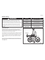 7
7
-
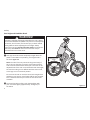 8
8
-
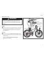 9
9
-
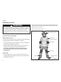 10
10
-
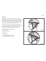 11
11
-
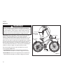 12
12
-
 13
13
-
 14
14
-
 15
15
-
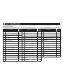 16
16
-
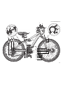 17
17
-
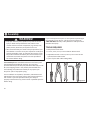 18
18
-
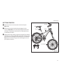 19
19
-
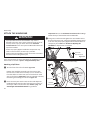 20
20
-
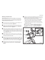 21
21
-
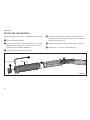 22
22
-
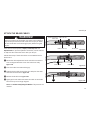 23
23
-
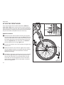 24
24
-
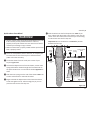 25
25
-
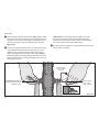 26
26
-
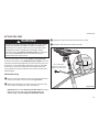 27
27
-
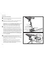 28
28
-
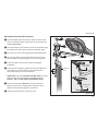 29
29
-
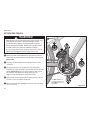 30
30
-
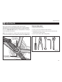 31
31
-
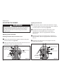 32
32
-
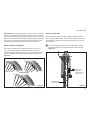 33
33
-
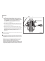 34
34
-
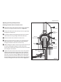 35
35
-
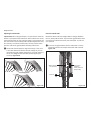 36
36
-
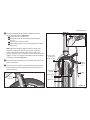 37
37
-
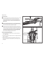 38
38
-
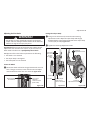 39
39
-
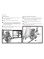 40
40
-
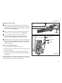 41
41
-
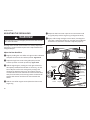 42
42
-
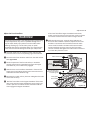 43
43
-
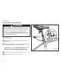 44
44
-
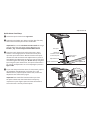 45
45
-
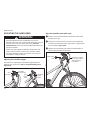 46
46
-
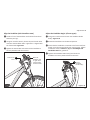 47
47
-
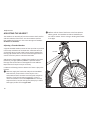 48
48
-
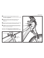 49
49
-
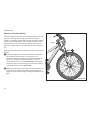 50
50
-
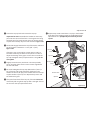 51
51
-
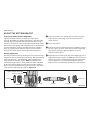 52
52
-
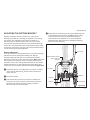 53
53
-
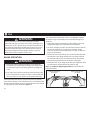 54
54
-
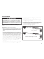 55
55
-
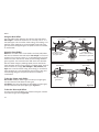 56
56
-
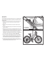 57
57
-
 58
58
-
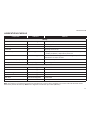 59
59
-
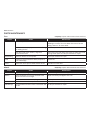 60
60
-
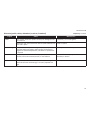 61
61
-
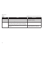 62
62
-
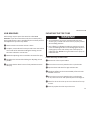 63
63
-
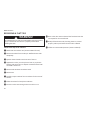 64
64
-
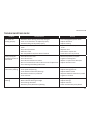 65
65
-
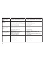 66
66
-
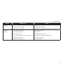 67
67
-
 68
68
-
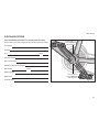 69
69
-
 70
70
-
 71
71
-
 72
72
-
 73
73
-
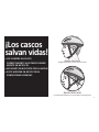 74
74
-
 75
75
-
 76
76
-
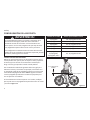 77
77
-
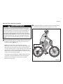 78
78
-
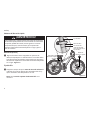 79
79
-
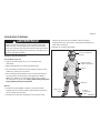 80
80
-
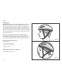 81
81
-
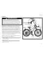 82
82
-
 83
83
-
 84
84
-
 85
85
-
 86
86
-
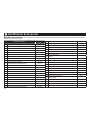 87
87
-
 88
88
-
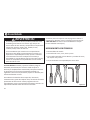 89
89
-
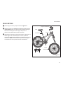 90
90
-
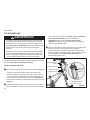 91
91
-
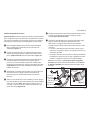 92
92
-
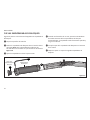 93
93
-
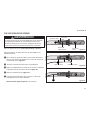 94
94
-
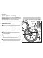 95
95
-
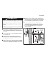 96
96
-
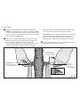 97
97
-
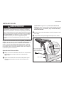 98
98
-
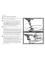 99
99
-
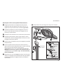 100
100
-
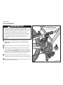 101
101
-
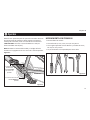 102
102
-
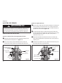 103
103
-
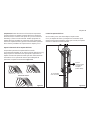 104
104
-
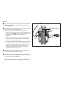 105
105
-
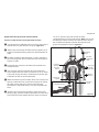 106
106
-
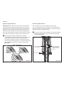 107
107
-
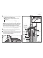 108
108
-
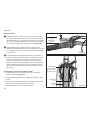 109
109
-
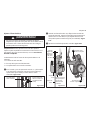 110
110
-
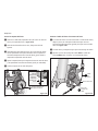 111
111
-
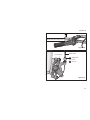 112
112
-
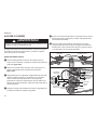 113
113
-
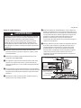 114
114
-
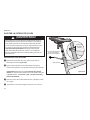 115
115
-
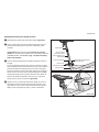 116
116
-
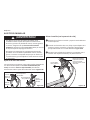 117
117
-
 118
118
-
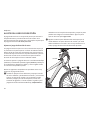 119
119
-
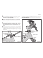 120
120
-
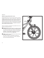 121
121
-
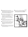 122
122
-
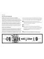 123
123
-
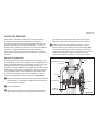 124
124
-
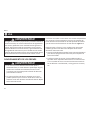 125
125
-
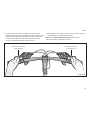 126
126
-
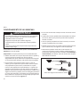 127
127
-
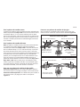 128
128
-
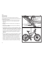 129
129
-
 130
130
-
 131
131
-
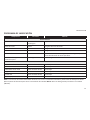 132
132
-
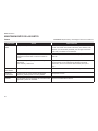 133
133
-
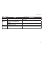 134
134
-
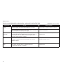 135
135
-
 136
136
-
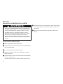 137
137
-
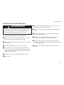 138
138
-
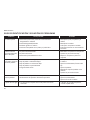 139
139
-
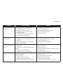 140
140
-
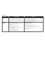 141
141
-
 142
142
-
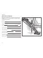 143
143
-
 144
144
-
 145
145


Mongoose 6061 El manual del propietario
- Categoría
- Bicicletas
- Tipo
- El manual del propietario
- Este manual también es adecuado para
en otros idiomas
- English: Mongoose 6061 Owner's manual
Artículos relacionados

Otros documentos
-
 Schwinn Bicycles BMX Bicycle El manual del propietario
-
 Schwinn Bicycles Cruiser Bicycle El manual del propietario
-
Schwinn Road Bicycle El manual del propietario
-
-
 Hover-1 H1-CZR28 Instrucciones de operación
-
Shimano BF-PA01 Service Instructions
-
AcuRite Rain Chain Manual de usuario
-
YOSE POWER E-bike Kits El manual del propietario
-
BENDIX SD-23-7541S Manual de usuario
-
Razor Sportmod El manual del propietario


