YOSE POWER E-bike Kits El manual del propietario
- Tipo
- El manual del propietario

E-bike Kits
UserManual
For 500W Rear Motor

Content
Appreciate for purchasing YOSE POWER electric bicycle Kits
Please turn to page 2 to obtain the user manual in English. 02
Gracias por comprar el kit de bicicleta eléctrica YOSE POWER
Para leer el manual en español, vaya a la página 09 09

1
Notices of user manual
Important information
E-Bike assembling & repair guide
Safety Regulation
When you install the product,please make sure that you observe all instructions provided by the user manual. It is suggested
that you use all components provided by yosepower. Serious injuries may be incurred due to damaged screws or because
the nuts suddenly malfunction.
Please make sure that you wear a goggle or other eye goggle device when you are repairing the bike or replacing
components.
If the content of the usermanualdoes not include your product, please browse the official website- www.yosepower.com,
or contact the yosepower team.
Please put the user manual in the proper place for reference in the future.
Please add the following items when our system users provide the descriptions written by themselves :
Pleasedo notpaytoomuchattentionto thescreenof theE-Bikedisplay whenyouareridingthebike, oraccidentsmaybe
incurred.
Pleasedo checkthewheelssets and the tiresarecorrectlyinstalled on thebike. Seriousinjuriesmay be incurredif youfailto
confirmthatthesecomponentsarecorrectlyinstalledon thebike.or contacttheyosepowerteamforassistance.
WhenyouareridingtheE-Bike,youshouldbe very familiarwiththecharacteristicsofthebikebeingactivatedor deactivated.
If the bikeis suddenlyactivatedbutyouarenot familiarwiththesecharacteristics,accidents will beincurred.
Please turn on the light if you ride the bike at night or in the place without sufficient light provision.
Please observe the safety instructions of the user manual for your safety.
Whenusingtheproduct,pleaseobservethesafetyinstructionsprovidedbythesafety inspectorortheusermanual,
theproductis not suitable for mental disabled, physicaldisable or people without bicycle riding experienceand
relevant knowledge, including children.
Pleasedonotmodify thesystem.Thesystemwillbeoutoforderifyouimproperlymodifythesystem.
Pleasecontactfor help aboutthe installation and theadjustment of the productyosepowerteam.
Theproductis designedto be havethecompletely water-prooffunctionandcanbe safely usedin moistplaces.
However, please do not immerse the productinto water on purpose.
Pleasedo not usehigh-pressurewaterjet to washthebike.If watercontacts the components,thebikewillbe outof
order andthe components will be rusted.
Please handle product with care to prevent from serious impact.
Somesafety instructionsof theuser manualcanbe alsoseenin the relevant warningmarks on theproduct.
Please contact yosepowerfor any questions about maintenance team.
Abrasion due to normal use is not within the warranty range provided by us.
Pleaseremove the batterybefore you install the componentsand the cablesof theE-Bikein orderto prevent from accident.
WhenyouinstalltheE-Bike, pleasemake surethat you observe all instructionsof the user manual.If the screwsand nutsare
not correctly tightened or the components are damaged,the E-Bike may fall over and serious injuriesmay be incurred.
Thefrequenciesof maintenanceand repairwillbe differentaccordingto theusagesituationof the E-Bike.Thesystemof the
bikeshouldbe periodically cleaned by the proper cleaning products. If you need to cleanthe bike, please usea neutral
detergentandsoft clothorlow-pressurewaterjet to washthebike,andthedry thebike.Pleaseproperlyusethesuggested
oils to lubricate the rotational components.

2
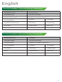
Cassette Freewheel / Tools and Packing Components
Screwed Freewheel / Tools and Packing Components
English
Installation tool
Components
Adiustable wrench
Hub motor with wheel
Freewheel chain wrench
Waterproof connection cable (4 in 1)
Cross screwdriver
Controller
LCD display
Cassette freewheel sleeve
PAS Sensor
Controller bag
Hex wrench
Thumb throttle
Brake lever
Puller
Installation tool
Material
Adiustable wrench
Hub motor with wheel
freewheel sleeve
Waterproof connection cable (4 in 1)
Cross screwdriver
Controller
LCD display
Hex wrench
PAS Sensor
Controller bag
Puller
Thumb throttle
Brake lever

3
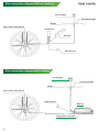
LCD display
Thumb throttle
Brake
Hub motor with wheel
Controller
Battery
PAS Sensor
Kits connection diagram(with battery)
LCD display
Thumb throttle
Brake
Hub motor with wheel
PAS Sensor
Battery
Integrated controller
Kits connection diagram(Without battery)

4
1
2
3
4
5
6
7
8
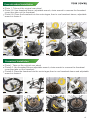
Freewheel installation
1
2
3
4
5
6
7
8
Cassette wheel installation
Photo 1: Take out the original rear wheel
Photo 3-5: Use freewheel sleeve, adjustable wrench, chain wrench to unscrew the freewheel
cover, then take out the freewheel.
Photo 6-8: Place the freewheel into the motor tagee, then to use freewheel sleeve, adjustable
wrench to fasten it.
Photo1: Take out the original rear wheel
Photo3-5: Use freewheel sleeve,adjustable wrench, chain wrench to unscrew the freewheel
cover,then take out the freewheel.
Photo6-8: Place the freewheel into the motor tagee,then to use freewheel sleeve and adjustable
wrench to fasten it.

5
1
2
3
4
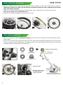
Rear wheel installation
Brake disk/Tire installation
Photo 1: Unscrew the original brake disc and then install it on the motor with the hex wrench
(Attention: Please use the screws from the motor to fasten the disc,otherwise the motor
may not work properly).
Photo 2,3: Remove the original tire and guard ring, install them on the motor wheel
(The guard ring can protect the tire).
Photo 4: Install the original tire to the motor hub.
Photo 1: place the washer(with part bulge), shim, and nut in sequence into both sides of the
motor axle.
Photo 2~4:Put the rear wheel into the rear fork, place the washer between the motor and fork,
then use the wrench to fasten the nut.Please note the motor cable should face down,cover the
waterproof plug, waterproof and dustproof.
(1)Shim
(2) Washer
(with part bulge)
* Washer install direction
(3) Nut (4)Waterproof cover
* Cable direction
* Spring sheath around
the cable corner to
protect the cable
2
3
1
4
2
3
1

6
1
2
3
4
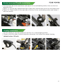
Display installation
1
2
3
4
Brake Lever and Throttle installation
Put the brake bar to the handle bar and adjust it to a comfortable position, then use the hex
wrench to fix it.
Photo 1,2: Pull out the original brake line of bike, then connect the line to the new brake lever.
Photo 3,4: Place throttle on the right side of the bar, find a comfortable position and fasten it
with hex wrench.
Put the display on the left handle bar and fix it in a comfortable position.
Please re-set the data of wheel diameter otherwise it will affect the speed showing
(default value: 26 inch)

7
1
2
3
4
5
6
7
8
9
10
11
12
Install the PAS in the left pedal side
Photo 1,2: Use the puller and hex wrench to take down the left and right cranks
Photo 5,8: Use sleeve to take down the left and right axis covers.Put the pas sensor into
the axis.
Attention: Firstly take down the left side axis cover;Then take down the right side axis
cover;
Photo 8~12: Firstly tighten the axis with sleeve,then use the hex wrench to close the crank.
Attention: The pas sensor disk must in counterclockwise
direction as showed.
13

8
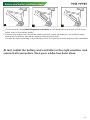
Battery and holder installation steps
1
2
3
Put the battery holder(with integrated controller) on the downtube and match to the screw
holes, then fix the battery holder.
Take out the battery and unlock the battery with key, insert the battery to the battery holder,
then block the battery, ensure the battery has been fixed well.
Connect all parts according to the drawing, check if all parts can work properly after installation.
At last, install the battery and controller in the right position, and
connect all connectors, then your e-bike has been done.

9
卡飞 Lista de herramientas y productos
旋飞 Lista de herramientas y productos
espa
的
l
Herramienta de instalaci6n
Material
Llave inglesa
Motor de cubo con rueda
Freewheel chain wrench
Cable de conexión impermeable (4 en 1)
Destornillador cruzado
Controlado
Pantalla LCD
Cassette freewheel sleeve
PAS Sensor
Bolsa de controlador
Llave hexagonal
Acelerador
Freno de mano
Herramientas para tirar
Herramienta de instalaci6n
Material
Llave inglesa
Motor de cubo con rueda
Freewheel sleeve
Cable de conexión impermeable (4 en 1)
Destornillador cruzado
Controlado
Pantalla LCD
Llave hexagonal
PAS Sensor
Bolsa de controlador
Herramientas para tirar
Acelerador
Freno de mano

10
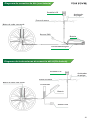
Pantalla LCD
Acelerador
de pulgar
Frono de mano
Motor de cubo con rueda
Sensor PAS
Batería
Controladorintegrad
Diagrama de instrucciones de conexión del kit(Sin batería)
Pantalla LCD
Acelerador
de pulgar
Frono de mano
Motor de cubo con rueda
Controlado
Batería
Sensor PAS
Diagrama de conexión de kits (con batería)

11
1
2
3
4
5
6
7
8
旋式飞轮安装
1
2
3
4
5
6
7
8
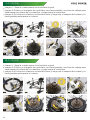
卡式飞轮安装
Imagen 1: Saca la rueda trasera de la bicicleta original.
Imagen 3-5:Utilice un manguito de rueda libre, una llave ajustable, una llave de cadena para
desenroscar la cubierta de la rueda libre y luego saque la rueda libre.
Imagen 6-8:Coloque el volante en la base del motor y luego use el casquillo del volante y la
llave ajustable para apretar el volante.

12
1
2
3
4
Instale la rueda trasera
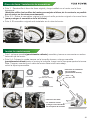
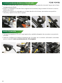
Disco de freno / instalación de neumáticos
Foto 1:Desatornille el disco de freno original y luego instálelo en el motor con la llave
hexagonal.
(Atención:utilice los tornillos del motor para sujetar el disco, de lo contrario,es posible
que el motor no funcionecorrectamente)
Foto 2-3:Retire el neumático original y mueva el anillo protector original a la nueva llanta
(para proteger el neumático de la bicicleta)
Foto 4: El neumático original está instalado en el cubo del motor.
Foto1: coloque arandela(parcialmente saliente), arandela y tuerca en secuencia en ambos
lados del eje del motor.
Foto 2-4: Coloque la rueda trasera en la horquilla trasera, coloque arandela
(parcialmente saliente) entre el motory la horquilla, luego use la llave para apretar la tuerca.
Nota: Tenga en cuenta que el cable del motor debe mirar hacia abajo,
cubrir la tapa impermeable.
(1)Arandela
(2)Arandela
(parcialmente saliente)
* Dirección de instalación
de la arandela
(parcialmente saliente)
(3) Tuerca (4) la tapa impermeable.
* Dirección del cable
* La funda de resorte
protege la línea alrededor
de la esquina de la salida.
2
3
1
4
2
3
1

13
1
2
3
4
Instale la pantalla
1
2
3
4
Instale la palanca de freno y el acelerador
Coloque la barra de freno en el manillar y ajústela a una posición cómoda, luego use la llave
hexagonal para fijarla.
photo1-2: Extraiga la línea de freno original de la bicicleta, luego conecte la línea a la nueva
palanca de freno.
photo3-4: Coloque el acelerador en el lado derecho de la barra, encuentre una posición
cómoda y fíjela con hex llave inglesa.
Coloque la pantalla LCD en el asa izquierda y apriétela después de encontrar una posición
cómoda.
Vuelva a configurar los datos del diámetro de la rueda; de lo contrario, afectará la velocidad
que se muestra (valor predeterminado: 26 pulgada)

14
1
2
3
4
5
6
7
8
9
10
11
12
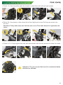
Install the PAS in the left pedal side
Photo 1,2: Use the puller and hex wrench to take down the left and right cranks
Photo 5,8: Use sleeve to take down the left and right axis covers.Put the pas sensor into
the axis.
Attention: Firstly take down the left side axis cover;Then take down the right side axis
cover;
Photo 8~12: Firstly tighten the axis with sleeve,then use the hex wrench to close the crank.
Attention: The pas sensor disk must in counterclockwise
direction as showed.
13

15
1
2
3
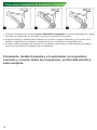
Pasos para la instalación de la batería y el soporte
Coloque el soporte de la batería (con controlador integrado) en el tubo descendente y haga
coincidir los orificios de los tornillos, luego fije el soporte de la batería.
Saque la batería y desbloquee la batería con la llave, inserte la batería en el soporte de la
batería, luego bloquee la batería, asegúrese de que la batería se haya fijado bien.
Conecte todas las piezas de acuerdo con el dibujo, compruebe si todas las piezas pueden
funcionar correctamente después de la instalación.
Finalmente, instale la batería y el controlador en la posición
correcta, y conecte todos los conectores, su bicicleta eléctrica
está completa.

16
Watch the installation video on youtube yosepower official channel
Europe USA
Official website
www.yosepower.com
Official website
www.yosepowershop.com
Marking
EC REP EUBRIDGE ADVISORYGMBH
Virginia Str. 2 35510 Butzbach,Germany eubridge@outlook.com Tel: 004915731153070
TANMET INT'L BUSINESS LTD
UK REP
9 Pantygraigwen Road, Pontypridd, Mid Glamorgan, CF37 2RR,UK tanmetbiz@outlook.com
Tel: 00442922550866
Batt-Reg.-Nr.DE 10983121
VerpackG:DE 5677895103216
WEEE-Reg-Nr:DE 31838004

-
 1
1
-
 2
2
-
 3
3
-
 4
4
-
 5
5
-
 6
6
-
 7
7
-
 8
8
-
 9
9
-
 10
10
-
 11
11
-
 12
12
-
 13
13
-
 14
14
-
 15
15
-
 16
16
-
 17
17
-
 18
18
-
 19
19


YOSE POWER E-bike Kits El manual del propietario
- Tipo
- El manual del propietario
En otros idiomas
Otros documentos
-
 Schwinn Bicycles Cruiser Bicycle El manual del propietario
-
 Schwinn Bicycles Hybrid Bicycle El manual del propietario
-
 Schwinn Bicycles Full Suspension Bicycle El manual del propietario
-
 Schwinn Bicycles Mountain Bicycle El manual del propietario
-
Schwinn Road Bicycle El manual del propietario
-
 Mongoose 6061 El manual del propietario
-
-
-
 Schwinn Bicycles Juvenile Bicycle El manual del propietario
-
 PJMASKS R0402TR Instrucciones de operación


