PJMASKS R0402TR Instrucciones de operación
- Categoría
- Bicicletas
- Tipo
- Instrucciones de operación
Este manual también es adecuado para

JUVENILE BICYCLE OWNER'S MANUAL
THIS MANUAL CONTAINS IMPORTANT SAFETY, PERFORMANCE AND MAINTENANCE
INFORMATION. READ THE MANUAL BEFORE TAKING YOUR FIRST RIDE ON YOUR NEW
BICYCLE, AND KEEP THE MANUAL HANDY FOR FUTURE REFERENCE.


Contents
1 Safety ............................................4
Safety Signal Words ...............................4
User Responsibility................................4
Bicycle Setup ....................................5
Personal Safety...................................8
Riding Safety....................................11
Before You Ride Safety Checklist ...................13
2 Parts Idencaon . . . . . . . . . . . . . . . . . . . . . . . . . . . . . . . . 14
3 Assembly . . . . . . . . . . . . . . . . . . . . . . . . . . . . . . . . . . . . . . . . 16
Tools Required . . . . . . . . . . . . . . . . . . . . . . . . . . . . . . . . . . 16
GengStarted..................................17
AachtheHandlebar.............................18
AachtheFrontBrakeCable . . . . . . . . . . . . . . . . . . . . . . 21
AachtheFrontWheel ...........................21
AachtheSeat..................................23
AachthePedals ................................24
AachtheTrainingWheels........................25
AachthePegs..................................28
4 Adjustments......................................29
Tools Required . . . . . . . . . . . . . . . . . . . . . . . . . . . . . . . . . . 29
AdjusngtheBrakes . . . . . . . . . . . . . . . . . . . . . . . . . . . . . 30
AdjusngtheSeatHeight . . . . . . . . . . . . . . . . . . . . . . . . . 37
AdjusngtheHandlebar . . . . . . . . . . . . . . . . . . . . . . . . . . 38
AdjusngtheHeadset ............................39
AdjusngtheBoomBracket......................41
5 Use..............................................42
BrakeOperaon.................................42
Security ........................................44
6 Maintenance . . . . . . . . . . . . . . . . . . . . . . . . . . . . . . . . . . . . . 45
Basic Maintenance ...............................45
LubricaonSchedule .............................46
Parts Maintenance . . . . . . . . . . . . . . . . . . . . . . . . . . . . . . 47
HubBearings....................................50
InangtheTireTube . . . . . . . . . . . . . . . . . . . . . . . . . . . . 50
RepairingaFlatTire ..............................51
TroubleshoongGuide ...........................52
7 Warranty.........................................55
Purchase Record.................................56

2
Congratulaons
onyournewbicycle!Properassemblyandoperaonofyour
bicycleisimportantforyoursafetyandenjoyment.Our
customerservicedepartmentisdedicatedtoyoursasfacon
withPacicCycleanditsproducts.Ifyouhavequesonsorneed
adviceregardingassembly,parts,performance,orreturns,
pleasecontacttheexpertsatPacicCycle.Enjoy the ride!
Toll free: 1-800-626-2811.
Customer Service hours:Monday-Friday8AM-5PMCentral
StandardTime(CST)
Youmayalsoreachusat:
Web:www.pacic-cycle.com
Email:customerservice@pacic-cycle.com
Mail: P. O. Box 344
4730 E. Radio Tower Lane
Olney,IL62450
Do not return this item to the store. Please call Pacic Cycle
customer service if you need assistance. You will need your
modelnumberanddatecodelocatedontheservicesckernear
theboombracketarea.SeeSecon 7: Purchase Record for the
locaonofthemodelnumberonyourbicycle.
About This Manual
Itisimportantforyoutounderstandyournewbicycle.
Byreadingthismanualbeforeyougooutonyourrstride,you’ll
knowhowtogetbeerperformance,comfort,andenjoyment
fromyournewbicycle.Itisalsoimportantthatyourrstrideon
yournewbicycleistakeninacontrolledenvironment,awayfrom
cars,obstaclesandothercyclists.
Thismanualcontainsimportantinformaonregardingsafety,
assembly,use,andmaintenanceofthebicyclebutisnot
intendedtobeacompleteorcomprehensivemanualcoveringall
aspectsconcerningbicycleownership.Werecommend
consulngabicyclespecialistifyouhaveanydoubtsorconcerns
regardingyourexperienceorabilitytoproperlyassembleand
maintainthebicycle.
A Special Note For Parents and Guardians
Itisatragicfactthatmostbicycleaccidentsinvolvechildren.
Asaparentorguardian,youbeartheresponsibilityforthe
acviesandsafetyofyourminorchild.Amongthese
responsibiliesaretomakesurethatthebicyclewhichyour
childisridingisproperlyedtothechild;thatitisingood
repairandsafeoperangcondion;thatyouandyourchild
havelearned,understandandobeynotonlytheapplicablelocal
motorvehicle,bicycle,andtraclaws,butalsothecommon
senserulesofsafeandresponsiblebicycling.Asaparent,you
shouldreadthismanualbeforelengyourchildridethe
bicycle.Pleasemakesurethatyourchildalwayswearsan
approvedbicyclehelmetwhenriding.

3
CorrectFing
Makesureyourhelmetcoversyourforehead
IncorrectFing
Foreheadisexposedandvulnerabletoseriousinjury
• ALWAYS WEAR A PROPERLY FITTED
HELMET WHEN RIDING YOUR BICYCLE
• DO NOT RIDE AT NIGHT
• AVOID RIDING IN WET CONDITIONS
Helmets
Save
Lives!

4
1 Safety
WARNING!
CAUTION!
SAFETY SIGNAL WORDS
The following safety signal words indicate a safety message.
The symbol alerts you to potenal hazards. Failure to follow the
warning may result in damage to property, injury, or death.
This manual contains many Warnings and Cauons concerning
the consequences of failure to follow safety warnings. Because
any fall can result in serious injury or even death, we do not
repeat the warning of possible injury or death whenever the risk
of falling is menoned.
Indicates a hazard or unsafe pracce that will result in severe
injury or death. Failure to read, understand and follow the safety
informaon in this manual may result in serious injury or death.
Indicates a hazard or unsafe pracce that could result in
minor injury.
Indicates a hazard unrelated to personal injury, such as
property damage.
❶ Safety
NOTICE
USER RESPONSIBILITY
All persons assembling, using, and maintaining the bicycle must
read and understand the safety warnings and operang
instrucons in this manual before using the bicycle.
It is the responsibility of the user, or in the case of a child rider,
an adult, to ensure the bicycle is properly maintained and in
proper operang condion. Doing so will reduce the risk of
injury. Always conduct regular maintenance and inspecon of
your bicycle. Complete the Safety Checklist at the end of this
secon before each use.
A responsible adult must always supervise the use of the bicycle
by a child. You must ensure:
WARNING!
• The child is wearing the proper protecve are and approved
bicycle helmet.
• The child is seated securely and the bicycle is properly ed
to the child.
• The child understands applicable laws and common sense
rules of safe responsible bicycling.
Do not install any kind of power plant or internal combuson
engine to a bicycle. Adapng a bicycle in this manner poses an
extreme safety risk to rider and could result in loss of control
or death.

Safety 1
5
Figure 1.1
BICYCLE SETUP
Correct Bicycle Size
Riding a bicycle that is not correctly sized to the rider may result
in the rider’s feet not being able to touch the ground and
balance the bicycle, properly reach the handlebar for steering or
braking, and loss of control when pedaling.
Use the wheel size in the following table as a guide to match the
rider and bicycle. For example, bicycles with a wheel size of 12
inches t a rider that is 28 to 38 inches tall. Note: Some bicycles
such as folding bicycles may have smaller wheels but sll t
adults.
If the bicycle has a top tube on the frame, check that there is
one to three inches of clearance between the rider and the top
tube. Figure 1.1
Inability to safely reach the handlebars and dismount the
bicycle may result in loss of control of the bicycle. If the
bicycle has a top tube on the frame, ensure there is one to
three inches of clearance between the rider and the top tube.
Improper setup or maintenance of the bicycle may result in
an unexpected movement, loss of control, and serious injury
or death.
WARNING!
Wheel Size Riders Approximate Height
12 inch 28 - 38 inches tall
16 inch 38 - 48 inches tall
18 inch 42 - 52 inches tall
20 inch 48 - 60 inches tall
24 inch 56 - 66 inches tall
26 inch, 27.5 inch,
29 inch, 700c
64 - 74 inches tall
1 to 3 inch
clearance
Top tube

6
1 Safety
Figure 1.2
Seat Height and Handlebar Reach
Improperly adjusted seat height could aect the rider’s ability
to reach the handlebar and pedals may result in an unexpected
movement, loss of control, and serious injury or death. Follow
these guidelines when adjusng the seat height. Always
ensure the seat post minimum inseron marks are below the
seat clamp and cannot be seen. Ensure the seat clamp is
locked and the seat cannot move.
WARNING!
❶ Your legs should be almost completely straight when the
pedal is in the down most posion, just a slight bend in
the knee. Figure 1.2
Note: The rider’s feet may not touch the ground easily. If
this is the case the rider can simply move forward o the
seat to mount and dismount the bicycle or the seat can be
adjusted lower if the rider is uncomfortable with the height,
but note that riding is more dicult with the seat too low,
as the legs are in an unnatural posion.
Do not raise the seat so much the knees lock straight when
pedaling or you have to move forward o the seat to pedal.
This is unsafe and the bicycle cannot be controlled in this
condion.
❷ You should be able to safely reach the handlebar with
your arms bent slightly (approximately 10 degrees) at
the elbow.
Adjust the seat
height
1
2

Safety 1
7
Figure 1.3
Improper setup or maintenance of the quick-release levers
may result in an unexpected movement, loss of control, and
serious injury or death. Before riding always check that the
quick-release lever is rmly locked in place and the seat does
not move.
Seat Post
❷ Ensure the seat post’s minimum inseron marks are not
visible above the seat clamp and the clamp is locked in
place. Figure 1.3
Note: See Secon 4: Adjusng the Seat Height if
adjustments are needed.
Quick-release Lever
WARNING!
Minimum inseron
marks are located
on the seat post
Quick-release
seat clamp
2
Seat post
Seat tube

8
1 Safety
Figure 1.4
Riding a bicycle without protecve gear, clothing, or a helmet
may result in serious injury or death. Always wear protecve
gear, clothing, and helmet when riding the bicycle. Ensure
protecve gear does not interfere with steering, braking, and
pedaling.
WARNING!
PERSONAL SAFETY
ProtecveGearandClothing
Always wear: Figure 1.4
• Colors that are easily seen and, if possible, reecve clothing.
• Clothing appropriate for the weather condions.
• Use of protecve gear such as pads for the knees and elbows
is highly recommended for children.
• A properly ed, ASTM or SNELL approved, bicycle helmet
shall be worn at all mes by riders of the bicycle. For
informaon regarding how to properly t a helmet visit:
hp://www.nhtsa.gov/people/injury/pedbimot/bike/
easystepsweb
Do not wear:
• Loose clothing parts, strings, or jewelry that may become
entangled with moving parts on the bicycle or interfere with
handling of the bicycle.
• Pants with loose pant legs. If necessary, always tuck pant legs
into a sock or use a leg band to avoid the clothing becoming
caught in the drive chain.
• Shoes with uned shoe laces.
Properly ed helmet
Elbow pads
Knee pads
Leg band
Shoes fastened
or ed
Easily seen or
reecve clothing

Safety 1
9
Figure 1.6
Figure 1.5
Helmet Use
Important! Many states have passed helmet laws regarding
children. Make sure you know your state’s helmet laws. It is your
job to enforce these rules with your children. Even if your state
does not have a children’s helmet law, it is recommended that
everyone wear a helmet when cycling. When riding with a child
carrier seat or trailer, children must wear a helmet.
It is strongly advised that a properly ng, ASTM or SNELL
approved, bicycle safety helmet be worn at all mes when riding
your bicycle. In addion, if you are carrying a passenger in a
child safety seat, they must also be wearing a helmet.
The correct helmet should: Figure 1.5
• Be comfortable
• Have good venlaon
• Fit correctly
• Cover forehead
Incorrecthelmetposion:Figure1.6
• Helmet does not cover the forehead

10
1 Safety
Figure 1.7
Missing, damaged, or dirty reectors will aect the ability of
others to see and recognize you as a moving bicyclist, increasing
the risk of being hit, serious injury or death. Always check the
reectors are in place and make sure they are clean, straight,
unbroken and securely mounted before riding the bicycle.
WARNING!
Important! Federal regulaons require every bicycle over 16
inches to be equipped with front, rear, wheel, and pedal
reectors. Many states require specic safety devices. It is your
responsibility to familiarize yourself with the laws of the state
where you ride and to comply with all applicable laws, including
properly equipping yourself and your bike as the law requires.
Bicycles under 16 inches are considered “sidewalk bicycles” and
may not be ed with reectors. These bicycles should not be
ridden on streets, at night or unsupervised by an adult.
Check and conrm the front and rear reectors are in the
correct posion: Figure 1.7
• FrontReector: Should aim forward (when viewed from
above) and be mounted so it is within 5 degrees of vercal.
• RearReector: Should aim straight back (when viewed from
above) and be mounted so it is within 5 degrees of vercal.
Reectors
Rear (red)
Plus or minus
5 degrees of
vercal
Front wheel
(white)
Rear wheel
(white)
Pedal (orange)
Front (white)

Safety 1
11
General Safety
• Familiarize yourself with all the bicycle’s features before
riding. Pracce gear shis, braking, and the use of toe clips
and straps, if installed.
• Always ride defensively in a predictable, straight line. Never
ride against trac.
• Expect the unexpected (e.g. opening car doors or cars backing
out of concealed driveways).
• Take extra care at intersecons and when preparing to pass
other vehicles.
• Maintain a comfortable stopping distance from all other
riders, vehicles and objects. Safe braking distances and forces
are subject to the prevailing weather condions. Do not lock
up the brakes. When braking, always apply the rear brake
rst, then the front. The front brake is more powerful and if it
is not correctly applied, you may lose control and fall.
• Always use the correct hand signals to indicate turning
or stopping.
• Obey the trac laws (e.g., stopping at a red light or stop sign,
giving way to pedestrians).
• Wear proper riding are, reecve if possible, and avoid
open toe shoes.
• Do not use items that may restrict your hearing and vision.
• Do not carry packages or passengers that will interfere with
your visibility or control of the bicycle.
RoadCondions
• Be aware of road condions. Concentrate on the path ahead.
Avoid pot holes, gravel, wet road markings, oil, curbs, speed
bumps, drain grates and other obstacles.
• Cross train tracks at a 90 degree angle or walk your bicycle
across.
Wet Weather
• When riding in wet weather always wear reecve clothing
and use safety lights to enhance visibility.
• Exercise extreme cauon when riding in wet condions.
• Ride at a slower speed. Turn corners gradually and avoid
sudden braking.
• Brake earlier, it will take a longer distance to stop.
• Pot holes and slippery surfaces such as line markings and train
tracks all become more hazardous when wet.
WARNING!
RIDING SAFETY
Riding the bicycle in unsafe condions (i.e. at night), in an unsafe
manner, or disregarding trac laws may result in an unexpected
movement, loss of control, and serious injury or death.

12
1 Safety
Night Riding
• Important! Riding a bicycle at night is not recommended.
Check your local laws regarding night riding.
• Ensure bicycle is equipped with a full set of correctly
posioned and clean reectors.
• Use a white light on the front and a red light on the rear.
Use lights with ashing capability for enhanced visibility.
• If using baery powered lights, make sure baeries are
well charged.
• Wear reecve and light colored clothing. Wear reecve
clothing and use safety lights for increased visibility.
• Ride at night only if necessary. Slow down and use familiar
roads with street lighng.
Hill Technique
• Gear down before a climb and connue gearing down as
required to maintain pedaling speed.
• If you reach the lowest gear and are struggling, stand up on
your pedals. You will then obtain more power from each
pedal revoluon.
• On the descent, use the high gears to avoid rapid pedaling.
• Do not exceed a comfortable speed; maintain control and
take addional care.
• Braking will require addional distance. Iniate braking slowly
and earlier than usual.
Cornering Technique
• Brake slightly before cornering and prepare to lean your body
into the corner.
• Maintain the inside pedal at the 12 o’clock posion and
slightly point the inside knee in the direcon you are turning.
• Keep the other leg straight, do not pedal through fast or ght
corners.
• Decrease your riding speed, avoid sudden braking and
sharp turns.
Safe Riding Rules for Children
• Many states require that children wear a helmet while cycling.
Always wear a properly ed helmet.
• Do not play in driveways or the road.
• Do not ride on busy streets.
• Do not ride at night.
• Obey all the trac laws, especially stop signs and red lights.
• Be aware of other road vehicles behind and nearby.
• Before entering a street: Stop, look le, right, and le again
for trac. If there’s no trac, proceed into the roadway.
• If riding downhill, be extra careful. Slow down using the
brakes and maintain control of the steering.
• Never take your hands o the handlebars, or your feet o the
pedals when riding downhill.

Safety 1
13
BEFORE YOU RIDE SAFETY CHECKLIST
Before every ride, it is important to carry out the following
safety checks. Do not ride a bicycle that is not in proper
workingcondion!
Accessories
□ The reectors are properly placed and not obscured. Note:
Bicycles 16” and under may not be equipped with reectors
since small children should not ride at night.
□ All other ngs on the bike are properly and securely
fastened, and funconing.
□ The rider is wearing a properly ed helmet (protecve gear
if necessary) and that clothing and loose items are properly
constrained.
Bearings
□ All bearings are lubricated, run freely and display no excess
movement, grinding or raling.
Brakes
□ The front and rear brakes work properly.
□ The brake shoe pads are not overly worn and are correctly
posioned in relaon to the rims.
□ The brake control cables are lubricated, correctly adjusted
and display no obvious wear.
□ The brake control levers are lubricated and ghtly secured
to the handlebar.
Chains
□ The chain is oiled, clean and runs smoothly.
Cranks and Pedals
□ The pedals are securely ghtened to the crank arms.
□ The crank arms are secured to the axle and are not bent.
Frame and Fork
□ The frame and fork are not bent or broken.
□ The quick-release clamps are locked in place.
Steering
□ The handlebar and post are correctly adjusted and
ghtened, and allow proper steering.
□ The handlebars are set correctly in relaon to the forks and
the direcon of travel.
□ The handlebar binder bolt is ghtened.
Wheels and Tires
□ The rims do not have dirt or grease on them.
□ The wheels are properly aached to the bicycle and axle.
□ The res are properly inated within the recommended
pressures displayed on the res sidewall.
□ The res have the proper amount of tread, no bulges or
excessive wear.

Part name Torque (in.-lb)
1 Handlebar grip -
2 Rear brake lever 55 - 70
3 Brake cable -
4 Handlebar -
5 Handlebar binder bolt(s) 145 - 200
6 Stem -
7 Stem binder bolt 100 - 120
8 Headset 175 - 260
9 Caliper brake assembly 50 - 70
9A Brake cable pinch bolt 50 - 70
9B Brake pads -
9C Brake pads hardware 50 - 60
10 Caliper brake aaching nut 70-85
11 Wheel axle nut (front) 180-240
11A Wheel axle nut (rear) 240-300
12 Tire -
13 Rim -
14 Spoke -
15 Valve stem -
Part name Torque (in.-lb)
16 Fork dropout -
17 Fork -
18 Pedal 300-360
19 Crank arm (1-piece) 300
19A Crank arm (3-piece) 390
20 Chain -
21 Chainwheel -
22 Boom bracket lockring 300
23 Seat post -
24 Seat post aaching hardware 130-170
25 Saddle (seat) -
26 Seat post clamp 60-80
27 Linear brake assembly -
27A Brake cable pinch bolt 50 -70
27B Brake pad -
27C Brake pad hardware 50-60
27D Brake spring -
27E Brake pivot bolt 17-20
28 Freewheel -
Juvenile Bicycle
Get to know the parts of your bicycle. This will help with assembly, maintenance, and troubleshoong. Models vary in color and style.
❷ Parts Idencaon
14

Parts Idencaon 2
15
2
1
5
3
13
21
25
26
23
15
17
19, 19A
14
20
6
24
7
12
11
18
4
9C
8
12
9
27C
27B
27A
9B
9A
10
11A
16
22
27D
27E
28
27E
27

3 Assembly
16
Figure 3.1
Figure 3.1
If you need replacement parts or have quesons pertaining to
the assembly of your bicycle, call the service line direct at:
1-800-626-2811. Monday - Friday 8:00 am to 5:00 pm Central
Standard Time (CST).
TOOLS REQUIRED
• Phillips head screw driver
• 4 mm, 5 mm, 6 mm and 8 mm Allen wrench
• Adjustable wrench or a 9 mm, 10 mm, 14 mm and 15 mm
open and box end wrenches
• A pair of pliers with cable cung ability
Your new bicycle was assembled and tuned in the factory and
then parally disassembled for shipping. You may have
purchased the bicycle already fully assembled and ready to
ride or in the shipping carton in the parally disassembled
form. The following instrucons will enable you to prepare
your bicycle for years of enjoyable cycling.
For more details on inspecon, lubricaon, maintenance and
adjustment of any area please refer to the relevant secons in
this manual. If you have quesons about your ability to
properly assemble this unit, please consult a qualied specialist
before riding.
❸ Assembly
WARNING!
• Improper assembly of this product may result in serious
injury or death. Always follow the instrucons in this
manual and check crical components (e.g. wheels, seat,
pedals, brakes, derailleurs, res) before each use.
• We recommend that you consult a bicycle specialist if you
have doubts or concerns as to your experience or ability to
properly assemble, repair, or maintain your bicycle. If your
bicycle was obtained assembled, we recommend that you
read these instrucons and perform checks specied in
this manual before riding.

Assembly 3
17
17
Figure 3.2
GETTING STARTED
❶ Open the carton from the top and remove the bicycle.
Figure 3.2
❷ Remove the straps and protecve packaging from the
bicycle. Important! Do not discard packing materials unl
assembly is complete to ensure that no required parts are
accidentally discarded.
❸ Inspect the bicycle and all accessories and parts for possible
shortages. It is recommended that the threads and all moving
parts in the parts package be lubricated prior to installaon.
Note: We recommend using a lithium based grease on the
parts before assembly.
Pedals
Seat
Frame
Seat post
Training
wheels (2)
Front
wheel
Handlebar
assembly

3 Assembly
18
Figure 3.4
Figure 3.3
ATTACH THE HANDLEBAR
There are two types of stems that aach the handlebar to the
steerer tube. It is either a quill or clamp (threadless) stem.
AachingaQuillStem
❶ Turn the front fork to face forward. Figure 3.3
Posion the handlebar assembly over the steerer tube. Look
at all the cables to be sure they run in a smooth arc from
the shier or brake lever to the front brake or cable stop on
the frame. Important! If they are twisted or kinked, the
shiing and braking will not work. Figure 3.4
❸ Insert the stem post into the steerer tube and adjust the
handlebar height unl the rider feels they have control of
the bicycle and are comfortable. See Secon 1, Fig. 1.2:
Seat Height and Handlebar Reach for guidelines.
WARNING!
• Improper aachment of the handlebar may result in
damage to the stem post, steering tube and result in loss of
control, serious injury or death. Ensure the minimum
inseron marks on the stem post are not visible above the
top of the headset.
• Failure to properly ghten handlebar components may
result in loss of control, serious injury or death. Always
check the handlebar cannot move and is secured to the
frame before riding the bicycle.
Important! Be sure the minimum inseron marks do not go
above the top of the headset and are not visible.
❸ Using a 6 mm Allen wrench ghten the stem binder bolt at
the top of the stem post. Check the handlebar binder bolt(s)
to be sure they are properly ghtened and the handlebar is
clamped in place. Note: See Secon 4: Adjusng the
Handlebar if adjustments are needed.
Stem binder bolt
Minimum inseron marks
Handlebar binder bolt(s)
Front fork
facing forward
Headset
Steerer
tube
Stem post
1
2
3

Assembly 3
19
19
Figure 3.6
Figure 3.5
AachingaThreadlessStem
Important! Do not disassemble the headset or lose any parts.
Be sure the end of the fork is on the ground or being held with
your free hand, because once you loosen the top cap the fork
assembly may fall out of the frame.
❶ Turn the front fork to face forward (ie: the fork dropout is in
the furthest forward posion). Figure 3.3
❷ Using a 5 mm Allen wrench loosen the top cap bolt on the
steerer tube and remove the top cap and bolt. Important!
Do not remove the spacers. Figure 3.5
❸ Posion the handlebar assembly over the steerer tube.
Look at all the cables to be sure they run in a smooth arc
from the shier or brake lever to the front brake or cable
stop on the frame. Important! If they are twisted or kinked,
the shiing and braking will not work.
❹ While holding the fork assembly in place, use a 6 mm Allen
wrench and loosen the stem pinch bolts. Slide the handlebar
assembly onto the steerer tube.
❺ Align and center the stem to the fork and wheel. Tighten the
stem pinch bolts unl there is no play between the stem and
stem tube. Note: There should be a 3 to 5 mm (1/8" - 3/16")
gap between the top of the stem and stem post. Figure 3.6
❻ Place the top cap onto the top of the steerer tube. Insert
and tighten the top cap bolt until it is snug. Do not over
tighten.
❼ Using a 5 mm Allen wrench ghten the top cap bolt. Do the
following checks to determine if the headset is properly set.
Tighten or loosen the top cap bolt if necessary.
• Li up the front wheel of the bicycle, if the wheel does
not move freely le to right the headset is too ght.
• Hold the handlebar, close the brakes and rock the fork
back and forth. If you hear a knock or clunking sound the
headset is too loose.
Note: If needed, see Secon 4: Adjusng the Headset for
more detailed informaon. See Secon 4: Adjusng the
Handlebar for informaon on aligning the handlebar.
Stem pinch
bolts
3
2
Top cap
and bolt
1/8" - 3/16"
(3 - 5 mm)
5
5

3 Assembly
20
WARNING!
Figure 3.7
Figure 3.8
Figure 3.9
ATTACH THE FRONT BRAKE CABLE
Failure to properly set the brakes may result in the inability to
stop the bicycle movement and cause serious injury or death.
Be sure the brakes are funconing properly before using the
bicycle.
If the brakes are not aached follow these steps:
❶ Rotate the cable adjustment barrel and cable nut unl the
slots are aligned with the slot on the brake lever body.
Figure 3.7
❷ Press the brake lever towards the grip.
❸ Slide the brake cable through the slots and place the cable
head into the brake lever. Figure 3.8
❹ Release the brake lever. Figure 3.9
❺ Lightly pull on the cable, and rotate the cable nut and cable
barrel so they are no longer aligned.
Note: See Secon 4: Adjusng the Brakes if adjustments are
needed.
Cable adjustment
barrel slot
Cable nut slot
Brake cable slot Brake lever
Cable head
Brake cable
4
2
5
3
1

Assembly 3
21
21
Figure 3.10
ATTACH THE FRONT WHEEL
There are two types of front wheel assemblies; nued with step
retaining washer, and nued with clip retaining washer.
Note: Quick-release wheels may be on both the front and rear
wheels or just one. Also, some re tread paerns have a
direcon, so compare your front re and rear re of the bicycle
so that both tread paerns face the same way.
NuedwithStepRetainingWasher
❶Posion the front wheel between the front fork legs with
the axle resng inside the fork drop outs. Important! Be
sure the wheel is as centered as possible between the fork
legs. Figure 3.10
❷ Place a step washer on each end of the axle. Note: The at
side of the step washer must be facing out, and the
protrusion on the washer must t into the fork drop out.
Figure 3.11
❸ Aach the two axle nuts on the axle. Tighten one nut part
way, then ghten the other nut. Repeat unl both sides are
ghtened securely. Be sure that the wheel is centered
between the fork legs.
❹ If the wheel is o center, loosen the axle nut on the side that
has a smaller gap between re and fork leg, and use your
hand to push the wheel to a centered posion; hold the
wheel with one hand, and ghten the axle nut and check
again. Repeat if needed to be sure the wheel is centered
and securely ghtened.
Axle
Fork
dropout
Step
retaining
washer
Axle
nut
Step
retaining
washer
Protrusion on
step retaining
washer ts into
the fork dropout
Axle
nut
Figure 3.11
2
3
1
2
3
2

3 Assembly
22
Figure 3.12
Figure 3.13
NuedwithClipRetainingWasher
❶ Loosen the axle nuts on the front wheel. If there is a washer
inside of the axle nut, it belongs outside of the fork
dropouts. Figure 3.12
❷ Posion the front wheel between the front fork legs with
the axle resng inside the fork drop out.
Important! Be sure the wheel is as centered as possible
between the fork legs.
❸ Place the clip retaining washer on the axle and slide it up
against the fork drop out. Make sure the hooked end is
inside the small hole of the fork dropout. Figure 3.13
❹ Place the two outer axle nuts on and ghten evenly. Tighten
one side part way, then ghten the other side and repeat
unl both sides are ghtened securely. Be sure that the
wheel remained centered between the fork legs.
❺ If it is o center, loosen the axle nut on the side that has a
smaller gap between re and fork leg and use your hand to
push the wheel to a centered posion; hold the wheel with
one hand and ghten the axle nut and check again.
Repeat if needed to be sure the wheel is centered and
securely ghtened.
Axle
nut
Axle
nut
Clip
retaining
washer
Clip
retaining
washer
Dropout
hole
Axle
Fork
dropout
Clip retaining
washer
inserted into
dropout hole
4
3
4
3
3

Assembly 3
23
23
Figure 3.14
ATTACH THE SEAT
Improperly adjusted seat height could aect the rider’s ability
to reach the handlebar and pedals resulng in unexpected
movement, loss of control, and serious injury or death. Follow
these guidelines when adjusng the seat height. Always
ensure the seat post minimum inseron marks are below the
seat clamp and cannot be seen. Ensure the seat clamp is
locked and the seat cannot move.
WARNING!
❶ Unlock the quick-release lever and insert the seat post into
the seat tube. Figure 3.14
❷ Adjust the seat height up or down unl the rider feels they
have control of the bicycle and is comfortable.
Important! Be sure the minimum inseron marks do not go
past the top of the seat clamp and are not visible. See
Secon 1, Fig. 1.2: Seat Height and Handlebar Reach.
❸ Close the quick-release lever and lock the seat in place.
If there is not enough pressure to hold the seat in place
open the quick-release lever. With one hand on the quick-
release lever and one hand on the adjustment nut, start to
hand ghten the adjustment nut unl you start to feel some
resistance against the post clamp. Do not aempt to ghten
by turning the quick-release lever. The quick-release lever is
for closing, the adjustment nut is for adjusng the pressure.
❹ Try to close the quick-release lever. If it closes easily, open it
up and ghten the adjustment nut further. If it is too dicult
to close, open the quick-release lever up and loosen the
adjustment nut a lile and try again.
Important! You should feel resistance when you close
the quick-release lever that should leave a temporary
impression on your ngers. Open and close the handle to
ensure the seat is securely locked in place.
Minimum
inseron marks on
the seat post
Seat post
Minimum
inseron
marks
Quick-release
lever
Quick-release
seat clamp
Adjustment nut
2
1
3

3 Assembly
24
WARNING!
Figure 3.15
❶ Match the pedal marked R with the right-hand crank arm,
and match the pedal marked L with the le-hand crank arm.
Figure 3.15
❷ Place the threaded pedal into the threaded hole on the
crank arm.
❸ By hand, slowly turn the spindle the correct direcon.
Clockwise for right side pedal, counterclockwise for le side
pedal. Important! Stop if you feel resistance! This may be
an indicaon the spindle is entering the hole at an
angle. Remove the spindle and repeat step two and three.
❹ If the spindle is entering the hole cleanly then use a 15 mm
wrench or pliers to ghten completely.
❺ Repeat steps 1- 4 for the remaining pedal.
ATTACH THE PEDALS
• Aachment of an incorrect pedal into a crank arm can strip
pedal threads and cause irreparable damage. Visually
match the R and L sckers on the pedal and crank arm
before aaching the pedals. Before your rst ride, please
check to ensure your pedals are aached correctly.
• It is very important that you check the crank set for correct
adjustment and ghtness before riding your bicycle.
The left pedal turns
counter-clockwise and
the right pedal turns
clockwise.
1
1
2
3
3

Assembly 3
25
25
Figure 3.16
Note: Not all bicycles will accept training wheels. If your bicycle
did not come stock with training wheels, please call Pacic Cycle
to help determine if aer-market training wheels can be
aached.
There are three dierent braces used to aach the training
wheels to the bicycle: the c-shape brace, the at brace and the
at brace with stabilizer. Determine which brace was included
with your bicycle and follow the instrucons below.
C-ShapeBrace
❶ Remove the outer axle nut and washer from the rear wheel
axle. Figure 3.16
❷ Place the brace stabilizer washer onto the axle and align the
washer so that the notch on the washer ts into the frame
drop out.
❸ Place the C-shaped wheel brace onto the axle.
ATTACH THE TRAINING WHEELS
Failure to properly assemble and set up the training wheels
may cause instability and p over resulng in serious injury or
death. Always check the training wheels before using the
bicycle.
❹ Replace the washer and axle nut. Tighten the axle nut
securely, making sure that the wheel brace stays in the
proper vercal posion.
❺ The elongated hole on the wheel brace allows the training
wheel height to be adjusted for proper t.
WARNING!
Brace stabilizer washer
C-shaped wheel brace
Axle nut
Training wheel
Rear wheel axle
Inner axle nut
DO NOT REMOVE!
2
3
Washer
4
5

3 Assembly
26
Flat Brace
❶ Remove the outer axle nut and washer from the rear
wheel axle. Figure 3.17
❷ Place the at wheel brace onto the axle.
❸ Place the brace stabilizer washer onto the axle and align it
so that the notch ts into the rear frame drop out.
❹ Replace the washer and axle nut.
❺ Tighten the axle nut securely, making sure that the wheel
brace stays in the proper vercal posion. The elongated
hole on the wheel brace allows the training wheel height to
be adjusted for proper t.
Brace stabilizer washer
C-shaped wheel brace
Axle nut
Training wheel
Rear wheel axle
Inner axle nut
DO NOT REMOVE!
2
3
Washer
4 5
4
Figure 3.17

Assembly 3
27
27
Figure 3.18
TrainingWheelStabilizerBracket
❶ Remove the outer axle nut and washer from the rear
wheel axle. Figure 3.18
❷ Insert the training wheel brace into the stabilizer bracket so
that the forked end of the stabilizer bracket faces in.
❸ Slide assembly onto the rear axle so that the forked end
hooks around the chain stay of the bicycle.
❹ Replace the axle nut and washer, secure ghtly.
❺ The elongated hole on the brace allows for raising and
lowering the training wheel to the proper height.
Stabilizer brace
Wheel brace
Axle nut
Washer
5
2
3
4

3 Assembly
28
Figure 3.20
ATTACH THE PEGS
Important! Periodically check to make sure pegs are ght.
Some models may come equipped with 2 or 4 pegs. To install:
❶ Do not loosen or remove axle nuts. Figure 3.19
❷ Check to make sure axle nuts are properly ghtened before
installing pegs.
❸ Thread the pegs on the axle over the axle nut.
❹ Insert a screwdriver or similar tool through the peg holes
and ghten by turning the peg with the tool. Figure 3.20
❺ Repeat steps three and four for the remaing pegs.
Figure 3.19
Axle nut
3
Peg
4
2

Adjustments 4
29
29
Figure 4.1
Figure 4.2
Aer your bicycle is assembled you will need to make
adjustments. If you need replacement parts or have quesons
pertaining to the assembly of your bicycle, call the service line
direct at: 1-800-626-2811. Monday - Friday 8:00 am to 5:00 pm
Central Standard Time (CST).
Note: You will need your model number and date code located
on the service scker near the boom bracket area. Figure 4.1
TOOLS REQUIRED
• Phillips head screw driver
• 4 mm, 5 mm, 6 mm and 8 mm Allen wrench
• Adjustable wrench or a 9 mm, 10 mm, 14 mm and 15 mm
open and box end wrenches
• A pair of pliers with cable cung ability
Service scker is
located above
the boom
bracket area.
The serial number is
located under the
boom bracket.
❹ Adjustments

4 Adjustments
30
Figure 4.3 Figure 4.4
ADJUSTING THE BRAKES
Failure to properly set the brakes may result in the inability
to stop the bicycle movement and cause serious injury or
death. Be sure the brakes are funconing properly before
using the bicycle.
WARNING!
Adjusng Linear Pull Brakes
Aaching the Brake Cable to the Brake Carrier
❶ Squeeze the two brake arms together unl the brake pads
touch the wheel rim. Figure 4.3
❷ With your other hand, pull on the brake cable and insert the
end of the “noodle” into the brake carrier.
Adjusng the Brake Pads
❸ Check the brake cable is seated in the brake lever. Using a 5
mm allen wrench loosen the cable anchor bolt enough so
the brake cable can move freely. Figure 4.4
❹ Pull the brake cable through the cable anchor so the
le brake arm moves towards the rim and there is
approximately a 1/8” (3 mm) gap between the brake
pad and rim.
❺ Move the right brake arm towards the rim unl there is
approximately a 1/8” (3 mm) gap between the brake pad
and rim.
❻ Using the 5 mm allen wrench, rmly ghten the cable
anchor bolt completely.
Cable anchor bolt
Wheel rim
5 mm Allen wrench
1/8” gap
(both pads)
Brake carrier
End of “noodle” in
the brake carrier
Brake arm
Brake cable
Brake arm
4
2
3
5
1

Adjustments 4
31
31
Figure 4.5
Figure 4.6
Important! Before riding the bicycle it is important to check the
brakes. If you squeeze the brake lever and one brake arm moves
more than the other (or not at all) the brake is not centered. You
will need to ne-tune the brake pads. Mulple adjustments may
be necessary to center the brake pads, correctly set the brake
pressure, and set the gap between the brake pad and rim.
Adjust the Brake Pad Alignment
Check that all brake pads are aligned correctly. If not, use a
5 mm allen wrench and loosen the bolt enough so you can
reposion the pad. Posion the pad so it is evenly centered on
the rim. Reghten the bolt aer posioning the pad correctly.
Figure 4.5
Center the Brake Pads
Rotate the wheel and look straight down at the gap between
the rim, brake pads, and fork. If you nd the gap between these
are uneven it indicates the wheel, the brake pads, or both are
not centered.
❶ If you see the gap between the fork and wheel is uneven
loosen the axle nuts and adjust the wheel unl centered.
Figure 4.6
1
Incorrect Alignment
Correct Alignment
Even space
between
wheel and fork
(both sides)
Wheel should
be centered

4 Adjustments
32
Figure 4.7
❷ If the gap between the brake pad and wheel is uneven,
adjust the posion of the brake pad.
• Using a phillips head screwdriver, adjust the brake arm
screws on either side of the brake arm. Note: Turning the
screw clockwise moves the pad away from the rim.
Turning the screw counterclockwise moves the pad
towards the rim. Figure 4.7
• Start with the side where the pad is closest to the rim or
is not moving properly. Turn the screw to move the pad
towards or away from the rim.
• Adjustments to these screws should be made in small
increments, one-quarter to one-half turn then checked
by acvang the brake lever three to four mes aer
each adjustment. If you connue to adjust the screw unl
you have noceable movement you will run out of
adjustment.
❸ Pull and release the brake lever a few mes and check if the
pads are centered.
❹ If necessary, repeat steps one through three unl the brake
pads are centered and the gap between the pads and rim is
close to 1/8 inch.
Note: If you run out of adjustment capability on one side,
adjust the screw on the opposite side. If you run out of
adjustment capability on both screws do a minor
adjustment to the brake cable. Adjustments should be made
to each side as equally as possible to prevent running out of
adjustment capability.
Even space between
brake pad and wheel
Brake arm screw
Brake arm
screw
2

Adjustments 4
33
33
Figure 4.8
Figure 4.9
Adjusng the Side-pull Caliper Brake
Aaching the Brake Cable to the Brake Carrier
❶ If the brake cable is disconnected at the caliper, thread the
brake wire through the adjustment barrel. Figure 4.8
❷ Loosen the cable anchor bolt unl you can see a gap large
enough for the cable wire.
❸ Thread the cable wire through the gap. By hand, screw the
cable anchor bolt snug enough to hold the cable wire.
❹ Check the cable end is seated in the brake lever.
❺ With one hand squeeze the caliper arms unl both brake
pads contact the rim. Loosen the cable anchor bolt just
enough to allow the cable wire to move freely.
❻ While holding the caliper closed, use your other hand to pull
the brake cable ght (through the cable anchor bolt).
Check that the cable end is seated in the brake lever and the
barrel adjuster of the brake.
❼ Tighten the cable anchor bolt as much as you can by hand
and then while sll squeezing the caliper arms unl both
brake pads contact the rim, ghten the cable anchor bolt
fully with a 10 mm box wrench. Note: Use the adjustment
barrel(s) to ne-tune the brake cable tension. Turning the
barrel clockwise will loosen the brake cable tension, counter-
clockwise will ghten the brake cable tension. Figure 4.9
Brake cable end at
brake lever
4
Cable
anchor bolt
Brake pad
Cable wire
Brake cable
Side-pull
caliper brake
Wheel rim
1
2
3
Cable
adjustment
barrel
5
Caliper
arms

4 Adjustments
34
Figure 4.11Figure 4.10
Adjusng the Brake Pads
Important! Before riding the bicycle it is important to check the
brakes. If you squeeze the brake lever and one brake arm moves
more than the other (or not at all) the brake is not centered. You
will need to ne-tune the brake pads. Mulple adjustments may
be necessary to center the brake pads, correctly set the brake
pressure and set the gap between the brake pad and rim.
❶ Check that all brake pads are aligned correctly. If not, use a
5 mm Allen wrench and loosen the bolt enough so you can
reposion the pad. Posion the pad so it is evenly centered
on the rim. Reghten the bolt aer posioning the pad
correctly. Figure 4.10
Center the Brake Pads
Rotate the wheel and look straight down at the gap between
the rim, brake pads and fork. If you nd the gap between these
are uneven it indicates the wheel, the brake pads, or both are
not centered.
❶ If you see the gap between the fork and wheel is uneven
loosen the axle nuts and adjust the wheel unl centered.
Figure 4.11
Even space
between
wheel and fork
(both sides)
Wheel should
be centered
Incorrect Alignment
Correct Alignment
Axle nut
1

Adjustments 4
35
35
1
Figure 4.13
❷ If the gap between the brake pad and wheel is uneven,
adjust the cable tension. Figure 4.13
2a
Loosen the cable anchor nut.
2b
Using one hand, squeeze the brake pads against
the rim.
2c
Pull the slack out of the cable.
2d
While holding tension on the cable, ghten the cable
anchor nut.
Note: Watch the brake if it begins to shi or rotate, then
release the brake lever and use your hand to rotate the
brake caliper back unl both sides of the brake move
equally. Somemes it is necessary to over-rotate the brake
slightly, so that as you ghten the caliper locknut, the brake
will end up centered. Figure 4.12
❸ Pull and release the brake lever a few mes and check if the
pads are centered.
❹ If necessary, repeat steps one through three unl the brake
pads are centered and the gap between the pads and rim is
close to 1/8 inch.
Brake pad
locknut
Brake pads
Tire
Wheel rim
Distance from
brake pad to
wheel rim 1/8”
Caliper
locknut
Cable
anchor
nut
2a
2c
3
4
Cable
Figure 4.12

4 Adjustments
36
Figure 4.15
Figure 4.14
Check the Brakes
❶ Aer adjusng the brake, squeeze the brake lever as hard as
you can several mes and re-inspect the brake pads,
centering and brake lever travel. If the brake pads are no
longer square to the rim, repeat brake pad adjustments.
Figure 4.14
❷ Be sure that brake pads return to a centered posion by
spinning the wheel and listening for the brake pad rubbing
the rim on either side. Re-adjust as needed.
❸ Check that the brake cable tension allows the brake lever
about 1/3 of the travel before the brake pads contact the
rim. If the cable has stretched or slipped, re-adjust the brake
cable tension by loosening cable anchor bolt and pulling
more cable through the anchor or use brake adjustment
barrels for ne tuning brake cable tension.
Brake is correctly adjusted when:
• The brake pads do not drag on the rim when the brake is
open. Figure 4.15
• Both brake pads move away from the rim equally when the
brake is released.
• When the brake is applied, the brake pads contact the rim
before the brake lever reaches about 1/3 of the way to the
handlebar.
Equal space
between brake
pad and the rim
on both sides
Brake pads
Wheel rim
1/3 distance to
handlebar
1

Adjustments 4
37
37
Figure 4.16
ADJUSTING THE SEAT HEIGHT
Improperly adjusted seat height could aect the rider’s ability
to reach the handlebar and pedals resulng in unexpected
movement, loss of control, and serious injury or death. Follow
these guidelines when adjusng the seat height. Always
ensure the seat post minimum inseron marks are below the
seat clamp and cannot be seen. Ensure the seat clamp is
locked and the seat cannot move.
WARNING!
❶ Unlock the quick-release lever. Figure 4.16
❷ Adjust the seat height up or down unl the rider feels they
have control of the bicycle and are comfortable.
Important! Be sure the minimum inseron marks do not go
past the top of the seat clamp and are not visible. See
Secon 1, Fig. 1.2: Seat Height and Handlebar Reach.
❸ Close the quick-release lever and lock the seat in place.
If there is not enough pressure to hold the seat in place
open the quick-release lever. With one hand on the quick-
release lever and one hand on the adjustment nut, start to
hand ghten the adjustment nut unl you start to feel some
resistance against the seat clamp. Do not aempt to ghten
by turning the quick-release lever. The quick-release lever is
for closing, the adjustment nut is for adjusng the pressure.
❹ Try to close the quick-release lever. If it closes easily, open it
up, and ghten the adjustment nut further. If it is too
dicult to close, open the quick-release lever up, and loosen
the adjustment nut a lile and try again.
Important! You should feel resistance when you close
the quick-release lever that should leave a temporary
impression on your ngers. Open and close the handle to
ensure the seat is securely locked in place.
Minimum
inseron marks on
the seat post
Seat post
Quick-release
lever
Quick-release
seat clamp
Adjustment nut
2
1
3
Minimum
inseron
marks

4 Adjustments
38
Figure 4.17
WARNING!
• Improper adjustment of the handlebar may result in
damage to the stem post, steering tube and result in loss of
control, serious injury or death. Ensure the minimum
inseron marks on the stem post are not visible above the
top of the headset.
• Failure to properly ghten handlebar components may
result in loss of control, serious injury or death. Always
check the handlebar is funconing properly and secured to
the frame before riding the bicycle.
ADJUSTING THE HANDLEBAR
Adjusng the Handlebar Height
Instrucons for adjusng the handlebar height depend on
whether your bicycle has a quill or clamp (threadless) stem.
Refer to Secon 3: Aach the Handlebar for instrucons on
adjusng the handlebar height.
Align the Handlebar
❶ Stand in front of the handlebar and hold the front wheel
between your legs.
❷ Using a 6 mm Allen wrench, loosen the stem binder bolt, or
pinch binder bolts, and move the handlebar le or right
unl it is aligned with the front wheel. Figure 4.17
❸ Tighten the stem binder bolt and check the handlebar is
securely aached and funconing properly.
Adjust the Handlebar Angle
❶ Using a 6 mm Allen wrench loosen the handlebar binder
bolt(s). Figure 4.17
❷ Rotate the handlebar into the desired posion.
❸ Check that the handlebar is centered to the frame and front
wheel. Sit on the seat and check your reach to grips,
shiers, and brakes. Refer to Secon 1: Seat Height and
Handlebar Reach for guidelines.
❹ Tighten the handlebar binder bolt(s) and check the
handlebar is securely aached and funconing properly.
Stem binder bolt
Note: The clamp
on threadless
stems have two
pinch binder bolts.
Handlebar binder bolt(s)
Stem post
4

Adjustments 4
39
39
ADJUSTING THE HEADSET
Threadless headsets are similar to threaded headsets, they use
two sets of bearings and bearing cups. Unlike a threaded
headset, a threadless headset does not have an upper threaded
race or use a threaded steerer tube. Instead the steerer tube
extends from the fork all the way through the head tube and
above the headset and is held in place by the stem clamped
on top.
Conduct the following checks to determine if there is play in the
headset:
❶ Shakiness: Apply the front brake and push the handlebars
back and forth, front to back. Or if the bicycle is on a
workstand and the front wheel removed, push and pull on
the forks. If you feel a knocking sensaon or "clunk" it
means the headset is too loose.
❷ Sness: Li the front of the frame so the front wheel is
o the ground. The handlebar and wheel should op to
one side or another. If there is drag or binding the headset
is too ght.
Figure 4.18
Headset
1
2

4 Adjustments
40
Figure 4.20
Figure 4.19
❶ Loosen the top cap bolt and remove the top cap.
Important! Do not disassemble the headset or lose any
parts. Be sure the end of the fork is on the ground or being
held with your free hand, because once you loosen the top
cap the fork assembly may fall out of the frame. Figure 4.19
❷ Check that the gap between the top of the steerer tube and
top of the stem is between 3 - 5 mm (1/8" - 3/16").
Figure 4.20
If the gap is not correct add or remove spacers unl it is.
The stem needs to press down on the spacers in order to
adjust the bearings. If the gap is correct then re-install the
top cap and tighten the top cap bolt until it is snug. Do not
over tighten.
❸ Slightly loosen the stem pinch bolts. The stem probably
won't move but make sure the stem remains aligned with
the fork and wheel.
❹ Re-install and ghten the top cap down with a 1/4 to 1/2
turn of the top cap screw and test for shakiness in the
headset. If there is sll play in the headset then turn the top
cap bolt another 1/4 to 1/2 turn. Repeat this process unl
the shakiness is gone.
❺ Li up the front wheel of the bicycle, if the wheel does not
move freely le to right the top cap bolt is too ght. If this is
the case turn the top cap bolt back some.
❻ Repeat steps 3 and 4 unl there is no play in the headset. If
the play in the headset cannot be reced with these
adjustments see a qualied bicycle mechanic for these
repairs.
Top cap
Star nut
Steerer tube
Stem pinch
bolts
Stem
Top cap
bolt
Spacers
1/8" - 3/16"
(3 - 5 mm)
2
1
3

Adjustments 4
41
41
Figure 4.21
ADJUSTING THE BOTTOM BRACKET
Typically the boom bracket contains four major pieces:
lockring, adjustable cone, bearings, and washers. The lockring
has notches. The adjustable cone will have notches for a
spanner wrench or boom bracket tool. The cones can be
removed and replaced separately. A set of round ball bearings
are found in each adjustable cone. A typical ball bearing is 5/16"
in diameter and contains nine balls. This type of boom bracket
may be cleaned, greased and adjusted.
Bearing Adjustment
The basic concept for bearing adjustments is to get the bearings
adjusted as loose as possible but without play. Start by
purposely beginning with play in the adjustment and then
ghtening in small increments unl play is gone. Note: Extended
use may cause the bearings, cups (or cones) to become worn
and pied. In this case, bearing adjustment will not be possible.
If boom bracket is correctly adjusted, but grinds when spun,
cups and/or cones are worn and should be replaced. Figure 4.21
❶ Loosen the locknut. Turn adjusng cone counter-clockwise
unl it hits the ball bearing, then turn back clockwise to
loosen 1/4 turn.
❷ Secure the locknut.
❸ Grab the end of the crank arms and rock it sideways to
check for play. If play is present, loosen locknut and turn
adjusng cone counter-clockwise slightly to ghten.
Re-secure locknut and check again.
❹ Repeat process of checking for play and re-ghtening cone a
slight amount unl no play is felt. Note: The one-piece crank
systems do not use a polished bearing system. There will be
some roughness to a correctly adjusted boom bracket.
Adjust as loose as possible but without play in the crank
assembly.
Boom bracket shown
with crank arm
removed
Locknut
Ball bearings
Crank arm
Chainwheel
Adjustable cones
Lockring
Crank arm
Washers

5 Use
42
WARNING!
Figure 5.1
BRAKE OPERATION
Failure to follow all local and state regulaons and laws
pertaining to bicycle use as well as the safety warnings in this
manual may result in serious injury or death. Always follow all
local and state regulaons and laws pertaining to bicycle use,
follow the safety warnings in this manual and use common
sense when riding the bicycle. Always conduct a pre-ride
check of the bicycle condion before riding.
There are two types of braking systems for bicycles; foot
operated and hand operated.
Foot Operated Brakes
Foot operated brakes allow the rider to pedal forward to
accelerate the bicycle, and pedal backwards to brake. The
harder you push back on the pedals, the more braking force is
applied to the rear wheel. Figure 5.1
In most cases a foot operated brake is strong enough to lock up
(stop the wheel from turning) the rear wheel and cause the re
to skid. While this will decelerate the bicycle quickly, it will also
cause unnecessary wear on the re, and terrain, and can cause a
loss of steering control.
It is recommended to pracce braking so that you have control
over how quickly the bicycle comes to a stop. It is also important
to know the environment that you are riding on. For example, a
dry paved road is very predictable when stopping. But if you add
rain, gravel, snow or anything else, the rider needs to be extra
careful, and allow extra stopping distance, and slow down
before turning. The rider should also be careful as terrain
changes to keep the bicycle at a controllable speed.
Some models may have a combinaon of foot and hand
operated brakes. It is OK to operate them at the same me or
independently. However, if the bicycle is equipped with a front
wheel hand brake, be careful to use front and rear brake
simultaneously, and avoid locking up the front wheel, as this can
cause a loss of steering control, and cause a crash. See hand
operated brakes on the next page for more detail.
❺ Use
Push backwards
to brake

Use 5
43
43
Figure 5.2
Hand operated brakes have a separate hand lever to operate
front and rear brakes. Front hand brake levers are located on
the le side of the handlebar, and rear hand brake levers are
located on the right side of the handlebar. Figure 5.2
Hand operated brakes may be used alone or on some models in
conjuncon with foot operated brakes. It is OK to operate one
brake at a me or all together, depending on your style,
comfort, and riding condions, however, be careful to pay close
aenon to front brakes locking up.
To best avoid this:
• Apply the front and rear brakes simultaneously, while shiing
your body weight back slightly to compensate for braking
force.
• As terrain changes, the rider must pracce and learn how the
bicycle will respond in a new terrain or weather change. The
same bicycle will react dierently if it is wet, or if there is
gravel on the road etc.
If the front brake is applied too quickly or too hard, the front
wheel can stop turning resulng in a front pitch over or cause
the bicycle to lose steering funcon leading to a crash.
Hand Operated Brakes
• Always test the brakes and be sure you feel comfortable with
the reacon. If the riding condions are too steep (o road
for example) and you are unsure, dismount the bicycle and
walk past the quesonable terrain before riding again.
• Remember that as you apply the brakes your weight will want
to shi forward, and the wheels will want to stop.
Note: See Secon 4: Adjusng the Brakes for informaon on
brake adjustment.
WARNING!
Pull to engage brakes

5 Use
44
Figure 5.4
Figure 5.3
SECURITY
You just bought a new bicycle! Don’t lose it. It is advisable that
the following steps be taken to prepare for and help prevent
possible the:
• Maintain a record of the bicycle’s model number. Serial
number is underneath the boom bracket. Model number is
above the boom bracket. Figure 5.3
• Register the bicycle with the local police and/or bicycle
registry.
• Invest in a high quality bicycle lock that will resist hacksaws
and bolt cuers.
• Always lock your bicycle to an immovable object if it is le
unaended. Keep in mind that individual parts of a bicycle
may be stolen. Most commonly, if you lock just a wheel or just
the frame, other parts may be removed from the bicycle.
Although it is impossible to lock all the parts, it is suggested
to lock the major components if possible. Figure 5.4
• Use a lock that is long enough to lock the frame and both
wheels if possible. Some models with quick-release front
wheels allow the front wheel to be placed beside the frame
so a smaller lock can be used to lock all 3 components.
• Be aware that a quick-release seat post can be stolen. It is
recommended to remove the seat post and saddle and carry
it with you if you believe that this is a risk.
Service scker
and model
number is located
above the boom
bracket area.
The serial number
is located under the
boom bracket.

Maintenance 6
45
• Failuretoconductmaintenanceonthebicyclemayresult
inmalfunconofacricalpartandseriousinjuryordeath.
Propermaintenanceiscricaltotheperformanceandsafe
operaonofthebicycle.
• Therecommendedintervalsandneedforlubricaonand
maintenancemayvarydependingoncondionsthebicycle
isexposedto.Alwaysinspectthebicycleandconduct
necessarymaintenancebeforeeachuseofthebicycle.
Thisseconpresentsimportantinformaononmaintenance
andwillassistyouindeterminingthepropercourseofaconto
takeifyoudohaveaproblemwiththeoperaonofthebicycle.
Ifyouhavequesonsregardingmaintenancepleasecallour
customerservice,tollfree,at1-800-626-2811 orseeaqualied
bicyclemechanic.Do notcallthestorewherethebicyclewas
purchased.
Correct roune maintenance of your new bike
will ensure:
• Smoothrunning
• Longerlasngcomponents
• Saferriding
• Lowerrunningcosts
BASIC MAINTENANCE
Thefollowingprocedureswillhelpyoumaintainyourbicyclefor
yearsofenjoyableriding.
• Forpaintedframes,dustthesurfaceandremoveanyloose
dirtwithadrycloth.Toclean,wipewithadampclothsoaked
inamilddetergentmixture.Drywithaclothandpolishwith
carorfurniturewax.Usesoapandwatertocleanplasc
partsandrubberres.Chromeplatedbikesshouldbewiped
overwitharustpreventaveuid.
• Storeyourbicycleundershelter.Avoidleavingitintherain
orexposedtocorrosivematerials.
• Ridingonthebeachorincoastalareasexposesyourbicycle
tosaltwhichisverycorrosive.Washyourbicyclefrequently
andwipeorsprayallunpaintedpartswithanan-rust
treatment.Makesurewheelrimsaredrysobraking
performanceisnotaected.Aerrain,dryyourbicycleand
applyan-rusttreatment.Ifthehubandboombracket
bearingsofyourbicyclehavebeensubmergedinwater,they
shouldbetakenoutandre-greased.Thiswillprevent
acceleratedbearingdeterioraon.
• Ifpainthasbecomescratchedorchippedtothemetal,use
touchuppainttopreventrust.Clearnailpolishcanalsobe
usedasapreventavemeasure.
• Regularlycleanandlubricateallmovingparts,ghten
componentsandmakeadjustmentsasrequired.
❻ Maintenance
WARNING!

6 Maintenance
46
LUBRICATION SCHEDULE
Note: Thefrequencyofmaintenanceshouldincreasewithuseinwetordustycondions.Donotoverlubricate.Removeexcess
lubricanttopreventdirtbuildup.Never useadegreasertolubricateyourchains(WD-40®).
Component Lubricant Method
Weekly
Chains Chainlubeorlightoil Brushonorsquirt
Brakecalipers O il Threedropsfromoilcan
Brakelevers Oil Twodropsfromoilcan
Freewheel Oil Twodropsfromoilcan
DerailleurSystems Lightoilorgrease Allpivotpointsshouldbelubricated(moreoeninseverelyrainy
ormuddycondions).Wipeoanyexcessoil.
Brakecables Lithiumbasedgrease Removecablefromcasing.Greaseenrelength.Wipeoexcess
lubricaonfromothersurfaces.
Brakeleverandcaliperpivotpoints Lightoil Twotothreedropsfromoilcan
Shiingcables Thinlayerofgrease Cleanandgrease
Yearly
Boombracket Lithiumbasedgrease Disassemble
Pedals Lithiumbasedgrease Disassemble
Wheelbearings Lithiumbasedgrease Disassemble
Headset Lithiumbasedgrease Disassemble
Seatstem Lithiumbasedgrease Disassemble
Pedals:thatcanbedisassembled Seebicyclemechanicformaintenance.

Maintenance 6
47
PARTS MAINTENANCE
Inspect Acon Maintenance
TireInaon Checkrepressure. Inateretothepressureindicatedontheresidewall.See
“InangaTireTube”formoredetail.Ifthereisatsee
“FixingaFlatTire”formoredetail.
Checkthebeadisproperlyseatedwhileinang
orrengthere.
Reduceairpressureinthetubeandre-seatthebead.
Spinwheelandcheckrotaon/alignment
issmoothandeven.
Loosenaxlenut(s)andadjustunlproperlyseated.Ifthehub
bearingsneedrepairseeabicyclemechanicforrepair.
BeadSeang Checkforbrokenorloosespokes. Seebicyclemechanicforrepair.
Tread Inspectforsignsofexcessivewear,atspotsor
cutsanddamage.
Replacere.
Valves Checkthatvalvecapsareedandfreeofdirt. Cleandirtfromthevalve.
Inspect Acon Maintenance
Rims Inspectfordirtandgrease. Useacleanragorwashwithsoapywater,rinse,andairdry.
Wheels Checkthewheelsaresecurelyfastenedtothe
bicycleandaxlenutsareght.
Adjustifnecessaryandghtenaxlenuts.
Spinwheelandcheckrotaon/alignmentistrue Seebicyclemechanicforrepair.
Spokes Checkforbrokenorloosespokes. Seebicyclemechanicforrepair.
HubBearings Lieachwheelandseeifthereismovementside
toside.
Seebicyclemechanicforrepair.
Frequency:Inspectandmaintainatleasteachuse
Frequency:Inspectandmaintainatleasteachuse
Tires
Wheels

6 Maintenance
48
Drivetrain (pedals, chains, chainwheel, crank set, freewheel)
Inspect Acon Maintenance
Pedals Everymonth,checkeachpedalissecurelysetandghteninto
thecrankarm.
Ifnecessary,re-setandghten.
Beforeeachride,checkeachfrontandrearpedalreectorsare
cleanandinplace.
Cleanorreplace.
PedalBearings Everyride,checkthepedalbearingsareproperlyadjusted.
Movethepedalupanddown,leandright.Ifloosenessor
roughnessisdetectedadjustment,lubricaonorreplacement
isrequired.
Seebicyclemechanicforrepair.
Chains Everyweek,checkthechainisclean,properlylubricated,
rust-free,andisnotstretched,broken,orhasslinks.
Lubricateifnecessary.Replaceifrusted,
stretched,orbroken.
CrankSet Everymonth,checkthecrankset(crankarms,chainrings,and
boombracketaxleandbearings)iscorrectlyadjustedand
ght.
Seebicyclemechanicforrepair.
Frequency:asnoted

Maintenance 6
49
Brakes
Inspect Acon Maintenance
Levers Checktheleversaresecurelyfastenedtothehandlebar. Posiontheleverstottherider’sgripand
screwghttohandlebar.
Pads Checkpadposion,gapandpressure. See Secon 4: Adjusng the Brakes
Cables Checktheoutercasingforkinks,stretchedcoilsanddamage.
Checkcablesforkinks,rust,brokenstrandsorfrayedends.
Checktheoutercasingforkinks,stretchedcoilsanddamage.
Replacecable.
Checkthehousingisseatedproperlyintoeachcablestopof
thebicycle.
Itisrecommendedthatthecablesand
housingbereplacedeveryridingseason.
Frequency:Inspectandmaintainbeforeeachuse

6 Maintenance
50
INFLATING THE TIRE TUBEHUB BEARINGS
Hubbearingsrequirespecialthinwrenchescalled cone
wrenches.Ifyoudonotownthesetools,donotaempthub
bearingadjustments.Haveaqualiedbicyclemechanicperform
theadjustmentifyouhaveanydoubts.
❶Checktomakesureneitherlocknutisloose.
❷Toadjust,removewheelfrombicycleandloosenthelocknut
ononesideofthehubwhileholdingthebearingconeon
thesamesidewithaconewrench.
❸Rotatetheadjusngconeasneededtoeliminatefreeplay.
❹Re-ghtenthelocknutwhileholdingtheadjusngconein
posion.
❺Re-checkthatthewheelcanturnfreelywithoutexcessive
sideplay.
Follow these steps to inate a re:
❶Removethevalvecapandaddair.
❷Besurethereisevenlyseatedontherim,bothsides.
❸Spinthewheelandcheckforhighandlowareas.
❹Completeinaontotherecommendedpsifoundonthe
sidewallofthere.
❺Besurethereisevenlyseatedontherim,bothsides.
Ifnot,releasesomeairandrepeatstepsthreethroughsix.
❻Checkfordirtinthevalvecaporstem.Cleandirtfromcap
orstem.
❼Securelyreplacethevalvecaponthestem.
• Anunseatedrecanruptureunexpectedlyandcause
seriousinjuryordeath.Besurethereisproperlyseated
wheninangthetube.
• Overinaonorinangthetubetooquicklymayresult
inthereblowingotherimanddamagingthebicycleor
causinginjurytotherider.Alwaysuseahandpumpto
inatethetube.Do notuseagasstaonservicepumpto
inatethetube.
WARNING!

Maintenance 6
51
Anunseatedrecanruptureunexpectedlyandcauseserious
injuryordeath.Besurethereisproperlyseatedwhen
inangthetube.
Follow these steps to x a at re:
❶Matchtubesizeandresize(seeresidewallforsize).
❷Removethewheelfromthebicycle.Deatetheretube
completely.
❸Squeezetherebeadsintothecenteroftherim.
❹Oppositethevalve,useabicyclerelevertoprythere
beadupandoutoftherim.Repeataroundthewheelunl
onebeadisotherim.
❺Removetube.Releasesecondrebead.
❻Removere.
❼Carefullyinspectinsideoftherimandreforthecauseof
theat.
❽Inatethetube¼fullandplaceinsidere.
❾Insertthevalvestemthroughvalvestemholeinrim.
REPAIRING A FLAT TIRE
❿Startatthevalvestemandinstalltherstbeadontothe
rim.Repeatforthesecondbead.
⓫Slowlyinatetheretube,checkingthereisseated
properlyandnotpinchedastheretubeisinated.
⓬Inatetorecommendedpressure(seeresidewall).
WARNING!

6 Maintenance
52
Problem Possible Cause Remedy
Slippingchain • Excessivelyworn/chippedchainringorfreewheelsprocket
teeth
• Chainworn/stretched
• Slinkinchain
• Noncompablechain/chainringfreewheel
• Replacechainring,sprocketsandchain
• Replacechain
• Lubricateorreplacelink
• Seekadviceatabicycleshop
Chainjumpingo
freewheelsprocket
orchainring
• Chainringoutoftrue
• Chainringloose
• Chainringteethbentorbroken
• Rearorfrontderailleurside-to-sidetraveloutofadjustment
• Crosschainingandshiingunderload
• Re-trueifpossible,orreplace
• Tightenmounngbolts
• Repairorreplacechainring/set
• Adjustderailleurtravel
Constantclicking
noiseswhen
pedaling
• Schainlink
• Loosepedalaxle/bearing
• Looseboombracketaxle/bearings
• Bentboombracketorpedalaxle
• Loosecrankset
• Lubricatechain/adjustchainlink
• Adjustbearings/axlenut
• Adjustboombracket
• Replaceboombracketaxleorpedals
• Tightencrankbolts
Grindingnoisewhen
pedaling
• Pedalbearingstooght
• Boombracketbearingstooght
• Chainfoulingderailleurs
• Derailleurjockeywheelsdirty/binding
• Adjustbearings
• Adjustbearings
• Adjustchainline
• Cleanandlubricatejockeywheels
Freewheeldoesnot
rotate
• Freewheelinternalpawlpinsarejammed • Lubricate.Ifproblempersists,replace
freewheel
TROUBLESHOOTING GUIDE

Maintenance 6
53
Problem Possible Cause Remedy
Brakesnotworking
eecvely
• Brakepadsworndown
• Brakepads/rimgreasy,wetordirty
• Brakecablesarebinding/stretched/damaged
• Brakeleversarebinding
• Brakesoutofadjustment
• Replacebrakepads
• Cleanpadsandrim
• Clean/adjust/replacecables
• Adjustbrakelevers
• Centerbrakes
Whenapplyingthe
brakestheysqueal/
squeak
• Brakepadsworndown
• Brakepadstoe-inincorrect
• Brakepads/rimdirtyorwet
• Brakearmsloose
• Replacepads
• Correctpadstoe-in
• Cleanpadsandrim
• Tightenmounngbolts
Knockingorshuddering
whenapplyingbrakes
• Bulgeintherimorrimoutoftrue
• Brakemounngboltsloose
• Brakesoutofadjustment
• Forklooseinheadtube
• Truewheelortaketoabikeshopforrepair
• Tightenbolts
• Centerbrakesand/oradjustbrakepadstoe-in
• Tightenheadset
Wobblingwheel • Axlebroken
• Wheeloutoftrue
• Hubcomesloose
• Headsetbinding
• Hubbearingscollapsed
• Quick-releasemechanismloose
• Replaceaxle
• Truewheel
• Adjusthubbearings
• Adjustheadset
• Replacebearings
• Adjustquick-releasemechanism

6 Maintenance
54
Problem Possible Cause Remedy
Steeringnot
accurate
• Wheelsnotalignedinframe
• Headsetlooseorbinding
• Frontforksorframebent
• Alignwheelscorrectly
• Adjust/ghtenheadset
• Takebiketoabikeshopforpossibleframerealignment
Frequent
punctures
• Innertubeoldorfaulty
• Tiretread/casingworn
• Tireunsuitedtorim
• Tirenotcheckedaerpreviouspuncture
• Tirepressuretoolow
• Spokeprotrudingintorim
• Replaceinnertube
• Replacere
• Replacewithcorrectre
• Removesharpobjectembeddedinre
• Correctrepressure
• Filedownspoke

Warranty 7
55
❼ Warranty
LIMITED WARRANTY AND POLICY ON REPLACEMENT PROCEDURES & RESPONSIBILITIES
Your purchase includes the following warranty which is in lieu of all other express warranes. This warranty is extended only to the inial consumer purchaser.
No warranty registraon is required. This warranty gives you specic legal rights and you may have other rights which vary from state to state.
FRAME
Steel frames are guaranteed against faulty materials and workmanship for as long as the inial consumer purchaser has the bicycle, subject to the condion of the
warranty listed below. Aluminum and dual suspension frames are guaranteed against manufacturing defects for a period of 5 years. If frame failure should occur due to
faulty materials or workmanship during the guarantee period, the frame will be replaced. For frame replacement under this Pacic Limited Warranty, contact us, stang
the nature of the failure, model number, date received and the name of the store from which the bike was received, at the address given on this page. Frame must be
returned for inspecon at customer’s expense. Please note: the fork is not part of the frame. A lifeme warranty on your frame does not guarantee that the product will
last forever. The length of the useful life cycle will vary depending on the type of bike, riding condions and care the bicycle receives. Compeon, jumping, downhill
racing, trick riding, trial riding, riding in severe condions or climates, riding with heavy loads or any other non-standard use can substanally shorten the useful product
life cycle. Any one or a combinaon of these condions may result in an unpredictable failure that is not covered by this warranty. All bicycles and frame sets should be
periodically checked by an authorized dealer for indicaons of potenal problems, inappropriate use or abuse. These are important safety checks and are very important
to help prevent accidents, bodily injury to the rider and shortened useful product life cycle.
PARTS
All other parts of the unit except Normal Wear Parts are warranted against defecve materials and workmanship for a period of 1 year from the date of purchase by the
inial consumer purchaser, subject to the Terms and Condions of the warranty listed below. If failure of any part should occur due to faulty materials or workmanship
during the warranty period, the part will be replaced. All warranty claims must be submied to the address below and must be shipped prepaid and accompanied by
proof of purchase. Any other warranty claims not included in this statement are void. This especially includes installaon, assembly, and disassembly costs. This warranty
does not cover paint damage, rust, or any modicaons made to the bicycle. Normal Wear Parts are dened as grips, res, tubes, cables, brake shoes and saddle
covering. These parts are warranted to be free from defects in material and workmanship as delivered with the product. Any claim for repair or replacement of Normal
Wear Parts (grips, tubes, res, cables, brake shoes and saddle covering) and missing parts must be made within thirty (30) days of the date of purchase. The warranty
does not cover normal wear and tear, improper assembly or maintenance, or installaon of parts or accessories not originally intended or compable with the bicycle as
sold. The warranty does not apply to damage or failure due to accident, abuse, misuse, neglect, or the. Claims involving these issues will not be honored.
CONDITIONS OF WARRANTY
1. Your bicycle has been designed for general transportaon and recreaonal use, but has not been designed to withstand abuse associated with stunng and jumping.
This warranty ceases when you rent, sell, or give away the bicycle, ride with more than one person, or use the bicycle for stunng or jumping.
2. This warranty does not cover ordinary wear and tear or anything you break accidentally or deliberately.
3. It is the responsibility of the individual consumer purchaser to assure that all parts included in the factory-sealed carton are properly installed, all funconal
parts are inially adjusted properly, and subsequent normal maintenance services and adjustments necessary to keep the bicycle in good operang condion are
properly made. This warranty does not apply to damage due to improper installaon of parts, installaon of any kind of power plant or internal combuson engine,
modicaon or alteraon of the brakes, drive train, or frame in any way, or failure to properly maintain or adjust the bicycle. NOTICE: Bicycle specicaons subject to
change without noce.
Pacic Cycle · PO Box 344 Olney, IL 62450

7 Warranty
56
Figure 7.1
PURCHASE RECORD
Fill in immediately and retain as a record of your purchase.
Please retain your sales receipt for any possible warranty claims.
Your Name:
Address:
City: State:
Date Purchased:
Place of Purchase:
Model & Brand Informaon:
Wheel Size: Color:
Model Number:
Date Code:
Serial Number:
Service scker
is located above
the boom
bracket area
The serial number is
located below the
boom bracket

MANUAL DE LA BICICLETA
ESTE MANUAL CONTIENE IMPORTANTE INFORMACION DE SEGURIDAD,
FUNCIONAMIENTO, Y MANTENIMIENTO. LEE EL MANUAL ANTES DE IR A EL PRIMER
PASEO EN SU BICICLETA NUEVA, Y GUARDE EL MANUAL REFERENCIA FUTURE.

Contenido
1 Seguridad . . . . . . . . . . . . . . . . . . . . . . . . . . . . . . . . . . . . . . . . . . . 4
Palabras De Advertencia De Seguridad .................4
Responsabilidad Del Usuario . . . . . . . . . . . . . . . . . . . . . . . . . 5
ConguraciónDeLaBicicleta .........................6
Seguridad Personal . . . . . . . . . . . . . . . . . . . . . . . . . . . . . . . . .9
SeguridadAlMontarEnBicicleta .....................12
ListaDeComprobaciónDeSeguridadAntes
DeMontarEnBicicleta .............................14
2 Idencación De Las Partes . . . . . . . . . . . . . . . . . . . . . . . . . . 16
3 Ensamblado.........................................18
HerramientasNecesarias............................18
ParaEmpezar .....................................19
Fije El Manillar.....................................20
FijeLosCablesDelFreno ............................22
InstaleLaRuedaDelantera . . . . . . . . . . . . . . . . . . . . . . . . . .23
Instalar El Sillín . . . . . . . . . . . . . . . . . . . . . . . . . . . . . . . . . . . .25
FijeLosPedales....................................26
InstaleLasRuedasDeAprendizaje ....................27
MontajeDeLasClavijas .............................30
4 Ajustes . . . . . . . . . . . . . . . . . . . . . . . . . . . . . . . . . . . . . . . . . . . . 31
Herramientasnecesarias ............................31
Ajustar los frenos . . . . . . . . . . . . . . . . . . . . . . . . . . . . . . . . . . 32
Ajustedelmanillar .................................40
Ajustedeljuegodedirección . . . . . . . . . . . . . . . . . . . . . . . . 41
5 Uso............................................ 44
Funcionamientodelosfrenos . . . . . . . . . . . . . . . . . . . . . 44
Seguridad . . . . . . . . . . . . . . . . . . . . . . . . . . . . . . . . . . . . . . 46
6 Mantenimiento . . . . . . . . . . . . . . . . . . . . . . . . . . . . . . . . . . 47
Mantenimientobásico............................48
Programadelubricación ..........................49
Mantenimientodelaspartes......................50
Rodamientosdelbuje . . . . . . . . . . . . . . . . . . . . . . . . . . . . 54
Desinelacámaradelallanta......................54
Reparar una llanta pinchada .......................55
Guíadeidencaciónysolucióndeproblemas .......56
Garana.......................................... 59
Garanalimitadadeporvidaypolícasobrelos
procedimientosdereemplazoyresponsabilidades ...59
Registrodecompra . . . . . . . . . . . . . . . . . . . . . . . . . . . . . . 60

2
¡Enhorabuena
porsunuevabicicleta!Esimportanteelmontajey
funcionamientocorrectosdesubicicletaparasuseguridady
disfrute.NuestrodepartamentodeServicioalClienteestá
dedicadoasusasfacciónconPacicCycleysusproductos.Si
enepreguntasonecesitaasesoramientoconrespectoal
montaje,partes,funcionamientoodevoluciones,póngaseen
contactoconlosexpertosenPacicCycle.¡Disfrute su
recorrido!
Llamada sin costo: 1-800-626-2811.
Horario de Servicio al Cliente:Delunesaviernesde8ama5pm
horarioestándarcentral(CST)
Tambiénpuedeencontrarnosen:
Web:www.pacic-cycle.com
Correo electrónico:customerservice@Pacic-Cycle.com
Correo:P.O.Box344
4730E.RadioTowerLane
Olney,IL62450
No devuelva este arculo a la enda. Llame a Servicio al Cliente
de Pacic Cycle si necesita ayuda. Necesitaráelnúmerodel
modeloyelcódigodefechaubicadosenlaequetadeservicio
cercadelazonadelpedalier.Veala sección 7: Registro de
compra paralaubicacióndelnúmerodemodeloensubicicleta.
Sobre este manual
Esimportantequeenendasunuevabicicleta.
Alleerestemanualantesdesalirensuprimerrecorrido,sabrá
cómoobtenermejorrendimiento,confortydisfrutedesunueva
bicicleta.Tambiénesimportantequerealiceelprimerrecorrido
enlanuevabicicletaenunambientecontrolado,lejosdelos
coches,obstáculosyotrosciclistas.
Estemanualconeneinformaciónimportantesobreseguridad,
montaje,usoymantenimientodelabicicleta,perono pretende
serunmanualcompletoointegralquecubratodoslosaspectos
relavosalaposesióndelabicicleta.Lerecomendamos
consultaraunespecialistaenbicicletassienedudaso
inquietudesconrespectoasuexperienciaocapacidadpara
montarymantenerlabicicletaadecuadamente.
Aviso especial para padres y tutores
Esunhechotrágicoquelamayoríadelosaccidentesdebicicleta
involucrananiños.Comopadreotutor,enelaresponsabilidad
delasacvidadesylaseguridaddesuhijomenor.Entreestas
responsabilidadesestáasegurarsedequelabicicletaquesuhijo
vaamontarseajustecorrectamentealniño;queestéenbuenas
condicionesyenunestadodefuncionamientoseguro;que
ustedysuhijohayanaprendido,enendanyobedezcannosólo
lasleyeslocalesaplicablesalosvehículosdemotor,lasbicicletas
yeltráco,sinotambiénlasreglasdesendocomúnsobre
cómomontarenbicicletademanerasegurayresponsable.
Comopadre,deberíaleerestemanualantesdepermirasu
hijomontarenlabicicleta.Asegúresedequesuhijosiempre
lleveuncascodebicicletahomologadocuandomontaen
bicicleta.

3
Ajuste correcto
Asegúresedequeelcascocubrasufrente
Ajuste incorrecto
Lafrenteestáexpuestayesvulnerablealesionesgraves
• USE SIEMPRE UN CASCO
CORRECTAMENTE AJUSTADO CUANDO
MONTE EN BICICLETA
• NO MONTE EN BICICLETA POR LA NOCHE
• EVITE MONTAR EN BICICLETA EN
CONDICIONES HÚMEDAS
¡Los cascos
salvan vidas!

4
1 Safety
❶ Safety
PALABRAS DE ADVERTENCIA DE
SEGURIDAD
Las siguientes palabras de advertencia de seguridad indican un
mensaje de seguridad. El símbolo lo alerta de riesgos
potenciales. No respetar la advertencia puede ocasionar daños
a la propiedad, lesiones o la muerte.
Este manual conene numerosas Advertencias y Precauciones
sobre las consecuencias que ene no respetar las advertencias
de seguridad. Ya que cualquier caída puede dar como resultado
lesiones graves o incluso la muerte, no reperemos la
advertencia de posibles lesiones o muerte cuando se mencione
el riesgo de caer.
Indica una prácca de riesgo o inseguridad que dará como
resultado lesiones graves o la muerte. No leer, entender y
respetar la información de seguridad de este manual puede dar
como resultado lesiones graves o la muerte.
Indica una prácca de riesgo o inseguridad que podría dar
como resultado una lesión leve.
Indica un riesgo no relacionado con lesiones personales, como
pueden ser los daños materiales.
AVISO
¡ADVERTENCIA!
¡PRECAUCIÓN!

Safety 1
5
RESPONSABILIDAD DEL USUARIO
¡ADVERTENCIA!
No instale ningún po de planta eléctrica o motor de
combusón interna en una bicicleta. Modicar una bicicleta
de esta manera plantea un riesgo de seguridad extremo para
el ciclista y puede dar como resultado la pérdida de control o
la muerte.
Todas las personas que ensamblen, usen y mantengan la
bicicleta deben leer y entender las advertencias de seguridad y
las instrucciones de operación de este manual antes de ulizar
la bicicleta.
Es responsabilidad del usuario o, en el caso de un niño ciclista,
de un adulto, asegurarse de que la bicicleta tenga un
mantenimiento correcto y esté en condiciones adecuadas de
funcionamiento. Hacerlo reducirá el riesgo de lesiones. Realice
siempre un mantenimiento regular y una inspección a su
bicicleta. Antes de cada uso, complete la lista de comprobación
de seguridad que está al nal de esta sección.
Un adulto responsable siempre debe supervisar el uso de la
bicicleta por parte de un niño. Debe asegurarse de que:
• El niño lleve la vesmenta protectora adecuada y un casco de
bicicleta homologado.
• El niño esté sentado de forma segura y la bicicleta esté
debidamente ajustada para el niño.
• El niño enende las leyes aplicables y las normas de sendo
común sobre el ciclismo responsable seguro.

6
1 Safety
Figura 1.1
Tamaño de la rueda Altura aproximada del ciclista
12 pulgadas 28 - 38 pulgadas de alto
16 pulgadas 38 - 48 pulgadas de alto
18 pulgadas 42 - 52 pulgadas de alto
20 pulgadas 48 - 60 pulgadas de alto
24 pulgadas 56 - 66 pulgadas de alto
26 pulgadas,
27,5 pulgadas,
29 pulgadas, 700 c
64 - 74 pulgadas de alto
CONFIGURACIÓN DE LA BICICLETA
La incapacidad para alcanzar el manillar y desmontar de la
bicicleta de forma segura puede dar como resultado la
pérdida de control de la bicicleta. Si la bicicleta ene una
barra superior en el cuadro, asegúrese de que haya de una a
tres pulgadas de espacio libre entre el ciclista y esa barra.
Una conguración o mantenimiento incorrectos de la bicicleta
pueden dar como resultado un movimiento inesperado, pérdida
de control, lesiones graves o la muerte.
¡ADVERTENCIA!
Tamaño correcto de la bicicleta
Montar en una bicicleta que no es del tamaño correcto para el
ciclista puede hacer que sus pies no toquen el suelo y equilibrar
la bicicleta, que no alcance correctamente el manillar para
dirigir o frenar y que pierda el control cuando pedalea.
Use el tamaño de rueda de la siguiente tabla como guía para
adecuar al ciclista y la bicicleta. Por ejemplo, las bicicletas con
un tamaño de rueda de 12 pulgadas se ajustan a un ciclista que
mida de 28 a 38 pulgadas de altura. Nota: Algunas bicicletas
como las plegables pueden tener ruedas más pequeñas pero
aun así ajustarse a los adultos.
Si la bicicleta ene una barra superior en el cuadro, verique
que haya de una a tres pulgadas de espacio libre entre el ciclista
y esa barra. Figura 1.1
1 a 3
pulgadas de
margen
Barra superior

Safety 1
7
Figura 1.2
Altura del sillín y alcance del manillar
La altura del sillín incorrectamente ajustada puede afectar la
capacidad del ciclista para alcanzar el manillar y los pedales, lo
que puede ocasionar un movimiento inesperado, pérdida de
control y lesiones graves o la muerte. Siga estas directrices para
ajustar la altura del sillín. Asegúrese siempre de que la marca de
inserción mínima de la ja del sillín esté por debajo de la
abrazadera del sillín y no se vea. Asegúrese de que la abrazadera
del sillín esté bloqueada y que éste no se pueda mover.
¡ADVERTENCIA!
❶ Sus piernas deben estar casi completamente rectas cuando
el pedal está en la posición más baja, con sólo una leve
curva en la rodilla. Figura 1.2
Nota: Los pies del ciclista no pueden tocar el suelo
fácilmente. Si este es el caso, el ciclista puede simplemente
adelantarse fuera del sillín para montar y desmontar de la
bicicleta o puede ajustarse el sillín más bajo si el ciclista está
incómodo con la altura, pero tenga en cuenta que es más
dicil circular con el sillín demasiado bajo, ya que las piernas
están en una posición poco natural.
No levante el sillín tanto que las rodillas se bloqueen rectas
al pedalear o tenga que adelantarse fuera del sillín para
pedalear. Esto es inseguro y la bicicleta no se puede
controlar en esta forma.
❷ Debe poder alcanzar el manillar con los brazos ligeramente
exionados (aproximadamente 10 grados) en el codo.
1
2
Ajuste la altura
del sillín

8
1 Safety
Figura 1.3
Tija del sillín
Asegúrese siempre de que la marca de inserción mínima de la
ja del sillín esté por debajo de la abrazadera del sillín y que la
abrazadera esté bloqueada en su sio. Figura 1.2
Nota: Vea la Sección 4: Ajustar la altura del sillín si es necesario.
Una conguración o mantenimiento incorrectos de las palancas
de liberación rápida pueden dar como resultado un movimiento
inesperado, pérdida de control, lesiones graves o la muerte.
Compruebe siempre, antes de montar, que la palanca de
liberación rápida esté rmemente jada en su lugar y que el
sillín no se mueva.
Palancas de liberación rápida
¡ADVERTENCIA!
Abrazadera de
liberación rápida
del sillín
Las marcas de
inserción mínima
están situadas en
la ja del sillín
Tija del sillín
Tubo del sillín
2

Safety 1
9
Montar en bicicleta sin equipo, ropa o casco de protección,
puede dar lugar a lesiones graves o la muerte. Use siempre
casco, ropa y equipo de protección cuando monte en bicicleta.
Asegúrese de que el equipo de protección no interera con la
dirección, frenado y pedaleo.
¡ADVERTENCIA!
Equipo y ropa de protección.
Use siempre: Figura 1.4
• Colores que sean fáciles de ver y, si es posible, ropa
reectante.
• Ropa adecuada para las condiciones del empo.
• Se recomienda vivamente el uso de equipo protector como
rodilleras y coderas para los niños.
• Los usuarios de bicicletas deben usar en todo momento un
casco ajustado correctamente, homologado por ASTM o
SNELL. Para obtener más información sobre cómo ajustar
correctamente el casco, visite: hp://www.nhtsa.gov/
people/injury/pedbimot/bike/easystepsweb
No use:
• Prendas de ropa holgadas, cadenas o joyas que puedan
engancharse en las partes móviles de la bicicleta o interferir
con el manejo de la bicicleta.
• Pantalones con perneras holgadas. Si es necesario, meta
SEGURIDAD PERSONAL
siempre las perneras en un calcen o ulice una pinza.
sujetapantalón para evitar que la ropa quede atrapada en la
cadena de transmisión.
• Zapatos con cordones desatados.
Figura 1.4
Casco correctamente
ajustado
Coderas
Rodilleras
Pinza para la
pierna
Zapatos
abrochados o
atados
Ropa fácilmente
visible o reectante

10
1 Safety
Figura 1.6
Figura 1.5
Uso del casco
¡Importante! Muchos estados han aprobado leyes sobre el uso
del casco con respecto a los niños. Asegúrese de conocer las
leyes sobre el uso del casco de su estado. Es su trabajo hacer
que sus hijos cumplan estas reglas. Aunque su estado no tenga
una ley sobre el uso del casco para niños, se recomienda que
todo el mundo ulice un casco cuando pracca ciclismo. Cuando
monte en bicicleta con un asiento o un remolque infanles, los
niños deben usar casco.
Se recomienda vivamente que ulice en todo momento un
casco de seguridad para bicicleta correctamente ajustado,
homologado por ASTM o SNELL. Además, si lleva pasajeros en
un asiento de seguridad infanl, también deberán llevar casco.
El casco correcto debe: Figura 1.5
• Ser cómodo
• Tener buena venlación
• Ajustarse correctamente
• Cubrir la frente
Posición incorrecta del casco: Figura 1.6
• El casco no cubre la frente

Safety 1
11
Figura 1.7
Los reectores faltantes, dañados o sucios, afectarán la
capacidad de los demás para verlo y reconocerlo como un
ciclista móvil aumentando el riesgo de ser golpeado, lesiones
graves o la muerte. Revise siempre que los reectores estén
en su lugar y asegúrese de que estén limpios, rectos, intactos
y rmemente instalados antes de montar en la bicicleta.
¡ADVERTENCIA!
¡Importante! Los reglamentos federales requieren que cada
bicicleta de más de 16 pulgadas se equipe con reectores
delanteros, traseros, en las ruedas y en los pedales. Muchos
estados requieren disposivos especiales de seguridad. Es su
responsabilidad familiarizarse con las leyes del estado donde
monta en bicicleta y cumplir todas las leyes aplicables,
incluyendo equiparse correctamente y equipar su bicicleta como
requiere la ley. Las bicicletas de menos de 16 pulgadas se
consideran "bicicletas de acera" y no podrán estar equipadas
con reectores. Estas bicicletas no deben circular en las calles,
de noche o sin la supervisión de un adulto.
Verique y conrme que los reectores delantero y trasero
estén en la posición correcta: Figura 1.7
• Reectordelantero: Debe apuntar hacia delante (visto desde
arriba) e instalarse de tal manera que no esté a más de 5
grados de la vercal.
Reectores
• Reectortrasero: Debe apuntar hacia atrás (visto desde
arriba) e instalarse de tal manera que no esté a más de 5
grados de la vercal.
Parte trasera
(rojo)
Más o menos
5 grados de
la vercal
Rueda
delantera
(blanco)
Rueda
trasera
(blanco)
Pedal (naranja)
Ruedas

12
1 Safety
Seguridad general
• Familiarícese con las caracteríscas de la bicicleta antes de
usarla. Pracque cambios de marcha, de frenado y el uso de
calapiés y correas, si están instalados.
• Circule siempre a la defensiva en una línea recta, predecible.
Nunca circule contra el tráco.
• Espere lo inesperado (por ejemplo, puertas de coche que se
abren o coches saliendo marcha atrás de salidas ocultas).
• Tenga mucho cuidado en las intersecciones y cuando se
prepare para adelantar a otros vehículos.
• Mantenga una distancia de parada cómoda respecto de todos
los demás ciclistas, vehículos y objetos. Las distancias y
fuerzas de frenado seguras están sujetas a las condiciones
climácas prevalecientes. No bloquee los frenos. Al frenar,
ulice siempre el freno trasero primero, luego el delantero.
El freno delantero es más potente y si no se aplica
correctamente, puede perder el control y caer.
• Ulice siempre las señales de mano correctas para indicar que
va a girar o a detenerse.
• Obedezca las leyes de tráco (por ejemplo, detenerse en un
semáforo en rojo o una señal de stop, dando paso a los
peatones).
• Use vesmenta adecuada para montar en bicicleta, de ser
posible reejante, y evite los zapatos de puntera abierta.
• No use arculos que puedan restringir su visión y audición.
• No lleve paquetes o pasajeros que intereran con su
visibilidad o control de la bicicleta.
Condiciones de la carretera
• Tenga en cuenta las condiciones de la carretera. Concéntrese
en el camino a seguir. Evite baches, grava, marcas de carretera
mojada, aceite, bordillos, badenes, alcantarillas y otros
obstáculos.
• Cruce las vías del tren en un ángulo de 90 grados o crúcelas
caminando con su bicicleta.
Tiempo húmedo
• Cuando monte en bicicleta con lluvia, ulice siempre ropa
reectante y luces de seguridad para mejorar la visibilidad.
• Extreme la precaución cuando circule en condiciones
húmedas.
• Circule a una velocidad más lenta. Gire las esquinas
gradualmente y evite los frenazos bruscos.
¡ADVERTENCIA!
SEGURIDAD AL MONTAR EN BICICLETA
Montar en bicicleta en condiciones inseguras (por ejemplo, en la
noche), de manera insegura o ignorando las leyes de tráco
puede dar como resultado un movimiento inesperado, pérdida
de control, lesiones graves o la muerte.

Safety 1
13
• Frene antes, le tomará una distancia mayor parar.
• Los baches y las supercies resbaladizas como las líneas
pintadas y las vías de tren se vuelven todos más peligrosos
cuando están mojados.
Montar en bicicleta en la noche
• ¡Importante! Montar en bicicleta por la noche no es
recomendable. Verique las leyes locales relavas a andar en
bicicleta por la noche.
• Asegúrese de que la bicicleta esté equipada con un conjunto
completo de reectores correctamente colocados y limpios.
• Ulice una luz blanca en el frente y una roja en la parte
trasera. Use luces con capacidad de destello para tener una
mejor visibilidad.
• Si uliza luces accionadas por baterías, asegúrese de que las
baterías estén bien cargadas.
• Use ropa reectora y de colores claros. Use ropa reectante y
luces de seguridad para mejorar la visibilidad.
• Sólo monte en bicicleta por la noche si es necesario. Circule
despacio y ulice carreteras iluminadas con las que esté
familiarizado.
Técnica de montaña
• Ponga una marcha menor antes de una subida y siga bajando
de marchas lo que sea necesario para mantener la velocidad
de pedaleo.
• Si alcanza la marcha más baja y sigue luchando, póngase de
pie sobre los pedales. Obtendrá más energía de cada
revolución del pedal.
• En el descenso, ulice las marchas largas para evitar pedalear
rápido.
• No supere una velocidad cómoda, mantenga el control y tome
precauciones adicionales.
• Frenar requerirá una distancia adicional. Inicie el frenado
lentamente y antes de lo habitual.
Técnica de giro
• Frene ligeramente antes de girar y prepárese para inclinar el
cuerpo en la esquina.
• Mantenga el pedal interior en posición de las 12 en punto y
apunte ligeramente la rodilla interior en la dirección en la que
gira.
• Mantenga la otra pierna recta; no pedalee cuando gire en
esquinas rápidas o cerradas.
• Disminuya la velocidad de su bicicleta, evite las frenadas
bruscas y los giros repennos.

14
1 Safety
LISTA DE COMPROBACIÓN DE SEGURIDAD ANTES DE MONTAR EN BICICLETA
Antesdecadarecorrido,esimportantellevaracabolas
siguientes comprobaciones de seguridad. ¡No monte en una
bicicleta que no esté en condiciones de funcionamiento
adecuadas!
Accesorios
□ Los reectores están colocados correctamente y no están
ocultos. Nota: Las bicicletas de 16" y menores no deben
estar equipadas con reectores dado que los niños
pequeños no deberían circular por la noche.
□ Todos los demás accesorios de la bicicleta están sujetos
correcta y seguramente, y funcionan
□ El ciclista lleva un casco correctamente ajustado (equipo de
protección si es necesario) y la ropa y arculos holgados
están correctamente controlados.
Rodamientos
□ Todos los rodamientos están lubricados, funcionan
libremente y no muestran ningún exceso de movimiento,
rechinidos o repiqueteo.
Frenos
□ Los frenos delantero y trasero funcionan correctamente.
□ Las zapatas del freno no están excesivamente desgastadas y
están colocadas correctamente en relación con los aros de
la rueda o rines.
□ Los cables de control de freno están lubricados, ajustados
correctamente y no muestran ningún desgaste evidente.
□ Las palancas de control del freno están lubricadas y
rmemente aseguradas al manillar.
Cadenas
□ La cadena está engrasada, limpia y funciona con suavidad.
Bielas y pedales
□ Los pedales están bien apretados a las bielas.
□ Las bielas están jadas al eje y no están dobladas.
Cuadro y horquilla
□ El cuadro y la horquilla no están doblados o rotos.
□ Las abrazaderas de liberación rápida están bloqueadas en su
lugar.

Safety 1
15
Dirección
□ El manillar y el poste están correctamente ajustados y
apretados, y permiten una dirección adecuada.
□ El manillar está ajustado correctamente en relación con las
horquillas y el sendo de la marcha.
□ El perno jador del manillar está apretado.
Ruedas y llantas
□ Los rines no enen grasa o suciedad en ellos.
□ Las ruedas están conectadas correctamente a la bicicleta y
el eje.
□ Las llantas están correctamente inadas dentro de las
presiones recomendadas que se muestran en el lateral de
las mismas.
□ Las llantas enen la candad apropiada de banda de
rodadura, sin protuberancias o desgaste excesivos

❷ Idencación de las partes
Bicicleta juvenil
Conozca las partes de su bicicleta. Esto ayudará con el armado, mantenimiento y solución de problemas. Los modelos varían de color y eslo.
Nombre de la parte
Par de torsión
(in-lb)
1 Empuñadura del manillar -
2 Maneta del freno trasero 55 - 70
3 Cable del freno -
4 Manillar -
5 Pernos jadores del manillar 145 - 200
6 Potencia -
7 Perno jador de la potencia 100 - 120
8 Juego de dirección 175 - 260
9 Conjunto del freno de pinza 50 - 70
9A Perno de jación del cable de freno 50 - 70
9B Zapatas del freno -
9C Material de montaje de las zapatas del freno 50 - 60
10 Tuerca de jación del freno de pinza 70-85
11 Tuerca del eje de la rueda (delantera) 180-240
11A Tuerca del eje de la rueda (trasera) 240-300
12 Llanta -
13 Rin -
14 Radio -
15 Vástago de la válvula -
Nombre de la parte
Par de torsión
(in-lb)
16 Punteras de la horquilla -
17 Horquilla -
18 Pedal 300-360
19 Brazo del cigüeñal (1 pieza) 300
19A Brazo del cigüeñal (3 pieza) 390
20 Cadena -
21 Plato -
22 Contratuerca del pedalier 300
23 Tija del sillín -
24 Material para jar la ja del sillín 130-170
25 Asiento (sillín) -
26 Abrazadera de la ja del sillín 60-80
27 Montaje del freno lineal -
27A Perno de jación del cable de freno 50-70
27B Zapata de freno -
27C Material de montaje de las zapatas del freno 50-60
27D Resorte del freno -
27E Perno del pivote del freno 17-20
28 Piñón libre -
16

Idencación de las partes 2
17
2
1
5
3
13
21
25
26
23
15
17
19, 19A
14
20
6
24
7
12
11
18
4
9C
8
12
9
27C
27B
27A
9B
9A
10
11A
16
22
27D
27E
28
27E
27

3 Montaje
18
• Unmontajedefectuosodeesteproductopuededarcomo
resultadograveslesionesolamuerte.Sigasiemprelas
instruccionesdeestemanualycompruebelos
componentescrícos(porejemplo,ruedas,sillín,pedales,
frenos,cambios,llantas)antesdecadauso.
• Lerecomendamosqueconsulteconunespecialistaen
bicicletassienedudasopreocupacionesencuantoasu
experienciaocapacidadparamontar,repararomantener
correctamentesubicicleta.Siadquiriósubicicletaya
ensamblada,lerecomendamosqueleaestasinstrucciones
yrealicelascomprobacionesespecicadasenestemanual
antesdesubirseaella.
Sinecesitapiezasderepuestooenepreguntasrelavasal
montajedesubicicleta,llamealalíneadeserviciodirectoal:
1-800-626-2811. Delunesaviernesde8:00ama5:00pm
horarioestándarcentral(CST).
HERRAMIENTAS NECESARIAS
• Destornilladordeestrella
• LlaveAllende4mm,5mm,6mmy8mm
• Llaveinglesaajustableollavesabiertasycerradasde9mm,
10mm,14mmy15mm
• Unpardealicatesconcapacidadparacortarcable
Su nueva bicicletasemontóyajustóenlafábricayluegose
desmontóparcialmenteparasuenvío.Puedecomprarla
bicicletayacompletamenteensambladaylistaparausarseoen
lacajadeenvíoenformaparcialmentedesmontada.Las
siguientesinstruccioneslepermiránprepararsubicicleta
paraañosdedisfrutedelciclismo.
Paraobtenermásdetallessobreinspección,lubricación,
mantenimientoyajustedecualquierárea,consultelas
seccionespernentesdeestemanual.Sienepreguntassobre
sucapacidadparaarmarcorrectamenteestaunidad,consulte
aunespecialistacalicadoantesdemontarenbicicleta.
Figura 3.1
❸ Ensamblado
¡ADVERTENCIA!

Ensamblado 3
19
19
PARA EMPEZAR
❶ Abralacajaporarribaysaquelabicicleta.Figura 3.2
❷ Quitelascorreasyelembalajedeproteccióndelabicicleta.
¡Importante!Norelosmaterialesdeembalajehastaque
termineelmontajeparaestarsegurodequenose
descartenaccidentalmentepiezasnecesarias.
❸ Inspeccionelabicicletaytodoslosaccesoriosypiezasporsi
faltasealguna.Serecomiendaquelasroscasytodaslas
piezasmóvilesdelpaquetedepiezasselubriquenantesdela
instalación.Nota: Lerecomendamosqueuliceunagrasa
conbasedelioenlaspiezasantesdeensamblarlas.
Figura 3.2
Pedales
Sillín
Cuadro
Tijadel
sillín
Ruedasde
aprendizaje(2)
Rueda
delantera
Conjunto
delmanillar

3 Montaje
20
Haydosposdesistemasparajarelmanillaraltubode
dirección.Esunapotenciade cuñaodeabrazadera (sin rosca).
Instalar una potencia de cuña
❶Girelahorquilladelanteraparaquemirehaciadelante.
Figura 3.3
Coloqueelconjuntodelmanillarsobreeltubodedirección.
Compruebetodosloscablesparaestarsegurodeque
recorranunarcosuavedesdelapalancadecambiosodel
frenohastaelfrenodelanterooeltopedelcableenel
cuadro.¡Importante!Siestántorcidosodoblados,no
funcionaránelcambionilosfrenos.Figura 3.4
❷ Inserteelpostedelapotenciaeneltubodedireccióny
ajustelaalturadelmanillarhastaqueelciclistasientaque
eneelcontroldelabicicletayestécómodo.VeaSección 1,
Fig. 1.2: Altura del sillín y alcance del manillarparaverlos
lineamientos.¡Importante!Asegúresedequelas marcas
de inserción mínimanovayanporencimadelaparte
superiordeljuegodedirecciónyqueno seanvisibles.
❸ UliceunallaveAllende6mmparaapretarelpernojador
delapotenciaenlapartesuperiordelpostedelapotencia.
Compruebelospernosjadoresdelmanillarpara
asegurarsedequeesténcorrectamenteapretadosyqueel
manillarestésujetoensulugar. Nota: Vealasección 4:
Ajuste del manillar siesnecesariohaceralgúnajuste.
Figura 3.4
FIJE EL MANILLAR
• Unainstalaciónincorrectadelmanillarpuededarcomo
resultadodañosalpostedelapotenciaodeltubode
direcciónyprovocarpérdidadecontrol,lesionesgravesola
muerte.Asegúresedequelas marcas de inserción mínima
delpostedelapotenciano seanvisiblesporencimadela
partesuperiordeljuegodedirección.
• Noapretarcorrectamenteloscomponentesdelmanillar
puededarcomoresultadolapérdidadelcontrol,lesiones
gravesolamuerte.Compruebesiemprequeelmanillarno
sepuedamoveryqueestéjadoalcuadroantesdemontar
enlabicicleta.
¡ADVERTENCIA!
Figura 3.3
1
2
3
Horquilladelantera
mirandohaciael
frente
Pernojador
delapotencia
Marcasdeinserciónmínima
Pernosjadoresdelmanillar
Juegodedirección
Tubodedirección
Postedelapotencia

Ensamblado 3
21
21
Instalar una potencia sin rosca
¡Importante!No desmonteeljuegodedirecciónnipierdaninguna
pieza.Asegúresedequeelextremodelahorquillaestéenelsuelo
oqueloestésujetandoconlamanolibre,porqueunavezaojela
tapasuperior,elconjuntodelahorquillapuedecaerdelcuadro.
❶ Girelahorquilladelanteraparaquemirehaciadelante(es
decir:lapunteradelahorquillaestáenlaposiciónmás
adelantada).Figura 3.3
❷ UsandounallaveAllende5mm,aojeelpernodelatapa
superiordeltubodedirecciónyquitetantolatapacomoel
perno.¡Importante!¡No quitelosespaciadores.Figura 3.5
❸
Coloqueelconjuntodelmanillarsobreeltubodedirección.
Compruebetodosloscablesparaestarsegurodeque
recorranunarcosuavedesdelapalancadecambiosodel
frenohastaelfrenodelanterooeltopedelcableenel
cuadro.¡Importante!Siestántorcidosodoblados,no
funcionaránelcambionilosfrenos.
❹ Sosteniendoelconjuntodelahorquillaensusio,uliceuna
llaveAllende6mmyaojelospernosdejacióndela
potencia.Desliceelconjuntodelmanillareneltubode
dirección.
❺ Alineeycentrelapotenciaconlahorquillaylarueda.Apriete
lospernosdejacióndelapotenciahastaquenohaya
holguraentreéstayeltubo.Nota: Debehaberunespaciode
3a5mm(1/8"-3/16")entrelapartesuperiordelapotencia
yelpostedelamisma.Figura 3.6
❻ Coloquelatapasuperiorencimadeltubodedirección.Inserte
yaprieteelpernodelatapasuperiorhastaquequede
ajustado.No lo apriete en exceso.
❼
UsandounallaveAllende5mm,aprieteelpernodelatapa
superior.Realicelassiguientescomprobacionesparadeterminar
sieljuegodedirecciónestácorrectamenteajustado.Aprieteo
aojeelpernodelatapasuperiorsifueranecesario.
• Levantelaruedadelanteradelabicicleta;sinosemueve
librementeaizquierdayderecha,eljuegodedirecciónestá
demasiadoapretado.
• Sostengaelmanillar,cierrelosfrenosybalanceelahorquilla
haciadelanteyhaciaatrás.Siescuchaungolpeteoosonido
metálico,eljuegodeladirecciónestádemasiadoojo.
Nota:Siesnecesario,veala sección 4: Ajustar el juego de
dirección paraobtenerinformacióndetallada.Veala sección
4: Ajustar el manillar paraobtenerinformaciónsobrecómo
alinearlo.
Figura 3.6
Figura 3.5
3
2
1/8"-3/16"
(3-5mm)
5
5
Pernosde
jacióndela
potencia
Tapasuperior
yperno

3 Montaje
22
Haytresopcionesdefreno,pinza, tracción lineal, y de disco.
Sigaestospasossiloscablesdefrenonoestánjadosalas
manetasdefreno:
❶ Gireelbarrildeajustedelcableylatuercadelcablehasta
quelasranurasesténalineadasconlaranuradelcuerpode
lamanetadefreno.Figura 3.6
❷ Presionelamanetadefrenohacialaempuñadura.
❸ Desliceelcabledelfrenoatravésdelasranurasycoloquela
cabezadelcableenlamanetadefreno.Figura 3.7
❹ Sueltelamanetadefreno.Figura 3.8
❺ Tireligeramentedelcableygirelatuercayelbarrildel
cableparaqueyanoesténalineados.
Nota:Sección 4: Ajuste los frenossiesnecesario
Unajusteincorrectodelosfrenospuededarcomoresultado
laincapacidaddedetenerelmovimientodelabicicletay
causarlelesionesgravesolamuerte.Asegúresedequelos
frenosfuncionancorrectamenteantesdeusarlabicicleta.
FIJE LOS CABLES DEL FRENO
¡ADVERTENCIA!
4
2
5
3
1
Ranuradelbarril
deajustedel
cable
Ranuradela
tuercadel
cable
Ranuradel
cabledefreno
Manetade
freno
Cabezadelcable
Cabledelfreno
Figura 3.6
Figura 3.7
Figura 3.8

Ensamblado 3
23
23
INSTALE LA RUEDA DELANTERA
Haydosposdemontajedelaruedadelantera;detuercacon
arandela de retención progresivaydetuercaconarandela de
retención de clip.
Nota:Lasruedasdeliberaciónrápidapuedenestartantoen
ambasruedascomosóloenuna.También,algunosdibujosdela
bandaderodamientodelallantaenenunadirección,asíque
comparelasllantasdelanteraytraseradelabicicletaparaque
ambosdibujosmirenhaciaelmismolado.
De tuerca con arandela de retención progresiva
❶Coloquelaruedadelanteraentrelaspatasdelahorquilla
delanteraconelejedescansandoenlaspunterasdela
horquilla.¡Importante!Asegúresedequelaruedaestélo
máscentradaposibleentrelaspatasdelahorquilla.
Figura 3.10
❷ Coloqueunaarandelaprogresivaencadaextremodeleje.
Nota:Laparteplanadelaarandelaprogresivadebeestar
mirandohaciafuera,yelsalientedelaarandeladebe
encajarenlahorquilladeretención.Figura 3.11
❸ Coloquelasdostuercasdelejeenelmismo.Aprieteuna
tuercaparcialmenteyluegolaotra.Repitahastaqueambos
ladosesténapretadosdemodoseguro.Asegúresedequela
ruedaestécentradaentrelaspatasdelahorquilla.
❹ Silaruedaestádescentrada,aojelatuercadelejedellado
quetengaunamenorseparaciónentrelallantaylapatade
lahorquilla,yulicelamanoparaempujarlaruedaauna
posicióncentrada;sujetelaruedaconunamano,aprietela
tuercadelejeyrevisedenuevo.Repitasiesnecesariopara
estarsegurodequelaruedaestécentradaybienapretada.
Figura 3.10
Elsalientedelaarandelade
retenciónprogresivaencajaen
lapunteradelahorquilla
Figura 3.11
2
Arandelade
retención
progresiva
Tuerca
deleje
Tuerca
deleje
2
3
3
2
Eje
Horquilla
puntera
1
Arandelade
retención
progresiva

3 Montaje
24
Arandelade
retenciónde
clipinsertada
eneloriciode
lapuntera
4
3
4
3
3
Figura 3.12
Figure 3.13
De tuerca con arandela de retención de clip
❶ Aojelastuercasdelejedelaruedadelantera.Sihayuna
arandelaenelinteriordelatuercadeleje,pertenecefuera
delaspunterasdelahorquilla.
❷ Posicionelaruedadelanteraentrelaspatasdelahorquilla
delanteraconelejedescansandodentrodelapunteradela
horquilla.Figura 3.12
¡Importante!Asegúresedequelaruedaestélomás
centrada
❸ Coloquelaarandeladeretencióndeclipenelejeydeslícela
haciaarribacontralapunteradelahorquilla.Asegúresede
queelextremocurvoestédentrodelpequeñooriciodela
punteradelahorquilla.Figura 3.13
❹ Coloquelasdostuercasexternasdelejeyapriételas
uniformemente.Aprieteparcialmenteunlado,luegoapriete
elotroladoyrepitahastaqueambosladosestén
rmementeapretados.Asegúresedequelaruedasehaya
mantenidocentradaentrelaspatasdelahorquilla.
❺ Siestádescentrada,aojelatuercadelejedelladoque
eneunamenorseparaciónentrelallantaylapatadela
horquilla,yuselamanoparaempujarlaruedaauna
posicióncentrada;sujetelaruedaconunamano,aprietela
tuercadelejeyrevisedenuevo.Repitasiesnecesariopara
estarsegurodequelaruedaestécentradaybienapretada.
Tuercadeleje
Tuerca
deleje
Arandela
de
retención
declip
Oricio
dela
puntera
Eje
Horquilla
puntera
Arandelade
retención
declip

Ensamblado 3
25
25
Figura 3.14
Laalturadelsillínincorrectamenteajustadapuedeafectarla
capacidaddelciclistaparaalcanzarelmanillarylospedales,
dandocomoresultadounmovimientoinesperado,pérdidade
control,lesionesgravesolamuerte.Sigaestasdirectricespara
ajustarlaalturadelsillín.Asegúresesiempredequelamarca de
inserción mínimadelajadelsillínestépordebajodela
abrazaderadelsillíny no sevea.Asegúresedequelaabrazadera
delsillínestébloqueadayqueéstenosepuedamover.
¡ADVERTENCIA!
INSTALAR EL SILLÍN
❶
Accionelapalancadeliberaciónrápidaeinsertelatijadelsillín
eneltubodelsillín. Figura 3.14
❷ Ajustelaalturadelsillínhaciaarribaoabajohastaqueelciclista
sientaqueeneelcontroldelabicicletayestécómodo.
¡Importante!Asegúresedequelas marcas de inserción
mínimanopasenlapartesuperiordelaabrazaderadelsillíny
no seanvisibles. VeaSección 1, Fig. 1.2: Altura del sillín y
alcance del manillar.
❸ Cierrelapalancadeliberaciónrápidaybloqueeelsillínensu
lugar.Sinohaysucientepresiónparasujetarelsillínensu
lugar,abralapalancadeliberaciónrápida.Conunamanosobre
lapalancadeliberaciónrápidayotraenlatuercadeajuste,
empieceaapretarlatuercadeajustehastaquecomiencea
senrciertaresistenciacontralaabrazaderadelaja.No
intenteapretargirandolapalancadeliberaciónrápida.La
palancadeliberaciónrápidaesparacerrar,latuercadeajuste
esparaajustarlapresión.
❹ Intentecerrarlapalancadeliberaciónrápida.Sisecierra
fácilmente,ábralayaprietemáslatuercadeajuste.Sisecierra
condemasiadadicultad,abralapalancadeliberaciónrápida,
aojelatuercadeajusteunpocoyvuelvaaintentarlo.
¡Importante! Alcerrarlapalancadeliberaciónrápidadebe
senrunaresistenciaquedebedejarunaimpresióntemporal
ensusdedos.Abraycierrelapalancaparaestarsegurodeque
elsillínestábloqueadodeformaseguraensulugar.
2
1
3
Tijadelsillín
Abrazaderade
liberaciónrápida
delsillín
Lasmarcasde
inserciónmínima
estánsituadasenla
jadelsillín
Tuercadeajuste
Palancade
liberación
rápida
Marcasde
inserción
mínima

3 Montaje
26
Figura 3.15
❶ HagacoincidirelpedalmarcadoRconlabieladerechay
hagacoincidirelpedalmarcadoLconlabielaizquierda.
Figura 3.15
❷ Coloqueelpedalroscadoeneloricioroscadodelabiela.
❸ Amano,girelentamenteelejeenladireccióncorrecta.
Hacialaderechaparaelpedalderechoyhacialaizquierda
paraelizquierdo.¡Importante!¡Paresiperciberesistencia!
Estopuedeserunaindicacióndequeelejeestáentrando
enánguloeneloricio.Rereelejeyrepitalospasos
dosytres.
❹ Sielejeestáentrandocorrectamenteeneloricio,ulice
unallavede15mmoalicatesparaapretarlo
completamente.
❺ Repitalospasos1al4paraelpedalrestante.
¡ADVERTENCIA!
FIJE LOS PEDALES
• Elajustedeunpedalincorrectoenunabielapuede
estropearelpedalycausardañosirreparables.Visualmente
hagacoincidirlaspeganasRyLdelpedalylabielaantes
decolocarlospedales.Antesdesuprimerrecorrido,
veriquequelospedalesesténcorrectamentecolocados.
• Esmuyimportantequecompruebeelajusteylarantez
correctosdelconjuntodelabielaantesdemontarsu
bicicleta.
1
1
2
3
3
Elpedalizquierdo
girahacialaizquierda
yelpedalde recho
girahacialaderecha.

Ensamblado 3
27
27
Figura 3.16
Nota: Notodaslasbicicletasaceptaránruedasdeaprendizaje.Si
subicicletanovinoconruedasdeaprendizaje,llameaPacic
Cycleparaqueleayudenadeterminarsipuedeninstalarse
ruedasdeaprendizajepostventa.
Seulizantresposdeabrazaderasdiferentesparasujetarlas
ruedasdeaprendizajealabicicleta:laabrazadera en forma de
C,la abrazadera planaylaabrazadera plana con estabilizador .
Determinequéabrazaderaseincluyóconsubicicletaysigalas
instruccionessiguientes.
Abrazadera en forma de C
❶ Quitelatuercaylaarandelaexternasdelejedelarueda
traseraFigura 3.16
❷ Coloquelaarandeladelestabilizadordelaabrazaderaenel
ejeyalineedichaarandelaparaquelamuescadelamisma
encajeenlapunteradelcuadro.
❸ ColoquelaabrazaderaderuedaenformadeCeneleje.
INSTALE LAS RUEDAS DE APRENDIZAJE
Noensamblaryajustarcorrectamentelasruedasde
aprendizajepuedeprovocarinestabilidadycaídas,dando
comoresultadolesionesgravesolamuerte.Compruebe
siemprelasruedasdeaprendizajeantesdeusarlabicicleta.
❹ Reemplacelaarandelaylatuercadeleje.Aprietelatuerca
delejermemente,paraestarsegurodequelaabrazadera
delaruedasemantengaenlaposiciónvercalcorrecta.
❺ Elagujeroalargadoenlaabrazaderadelaruedapermite
quelaalturadelaruedadeaprendizajeseajuste
correctamente.
¡ADVERTENCIA!
Arandeladel
estabilizadordela
abrazadera
Abrazaderadelarueda
enformadeC
Tuercadeleje
Ruedade
aprendizaje
Ejedelaruedatrasera
Tuercadelejeinterior
¡NOQUITAR!
2
3
Arandela
4
5

3 Montaje
28
Abrazadera plana
❶Quitelatuercaylaarandelaexternasdelejedelarueda
traseraFigura 3.17
❷Coloquelaabrazaderaplanadelaruedaeneleje.
❸ Coloquelaarandeladelestabilizadordelaabrazaderaenel
ejeyalinéelaparaquelamuescaencajeconlapuntera
traseradelcuadro.
❹Reemplacelaarandelaylatuercadeleje.
❺Aprietelatuercadelejermemente,paraestarsegurode
quelaabrazaderadelaruedasemantengaenlaposición
vercalcorrecta.Elagujeroalargadoenlaabrazaderadela
ruedapermitequelaalturadelaruedadeaprendizajese
ajustecorrectamente.
Figura 3.17
Arandeladel
estabilizadordela
abrazadera
Abrazaderadelarueda
enformadeC
Tuercadeleje
Ruedade
aprendizaje
Ejedelaruedatrasera
Tuercadelejeinterior
¡NOQUITAR!
2
3
Arandela
4
5

Ensamblado 3
29
29
Abrazadera plana
❶ Quitelatuercaylaarandelaexternasdelejedelarueda
traseraFigura 3.17
❷ Coloquelaabrazaderaplanadelaruedaeneleje.
❸ Coloquelaarandeladelestabilizadordelaabrazaderaenel
ejeyalinéelaparaquelamuescaencajeconlapuntera
traseradelcuadro.
❹Reemplacelaarandelaylatuercadeleje.
❺Aprietelatuercadelejermemente,paraestarsegurode
quelaabrazaderadelaruedasemantengaenlaposición
vercalcorrecta.Elagujeroalargadoenlaabrazaderadela
ruedapermitequelaalturadelaruedadeaprendizajese
ajustecorrectamente.
Figura 3.18
5
2
3
4
Abrazadera
estabilizadora
Abrazaderade
larueda
Tuerca
deleje
Arandela

3 Montaje
30
Figura 3.20
Figura 3.19
MONTAJE DE LAS CLAVIJAS
¡Importante!Reviseperiódicamenteparaestarsegurodeque
lasclavijasestánapretadas.Algunosmodelospuedenvenir
equipadoscon2o4clavijas.Parainstalarlas:
❶No aojeniquitelastuercasdeleje.Figura 3.19
❷ Compruebeparaestarsegurodequelastuercasdeleje
estánbienapretadasantesdeinstalarlasclavijas.
❸Enrosquelasclavijasdelejesobrelatuercadeleje.
❹ Introduzcaundestornilladorounaherramientasimilara
travésdelosoriciosdelaclavijayapriételagirándolacon
estaherramienta.Figura 3.20
❺ Repitalospasostresycuatroconlasclavijasrestantes.
3
4
2
Tuercadeleje
Clavija

Ajustes 4
31
31
❹ Ajustes
Figura 4.1
Figura 4.2
Deberá hacer ajustes después de que esté montada su bicicleta.
Si necesita piezas de repuesto o ene preguntas relavas al
montaje de su bicicleta, llame a la línea de servicio directo al:
1-800-626-2811. De lunes a viernes de 8:00 am a 5:00 pm
horario estándar central (CST).
Nota:Necesitará el número del modelo y el código de fecha
ubicados en la pegana de servicio cerca de la zona de
pedalier Figura 4.1
HERRAMIENTAS NECESARIAS
• Destornillador de estrella
• Llave Allen de 2,5 mm, 4 mm, 5 mm, 6 mm y 8 mm
• Llave inglesa ajustable o llaves abiertas y cerradas de 9 mm,
10 mm, 14 mm y 15 mm
• Un par de alicates con capacidad para cortar cable
La pegana
de servicio
está situada
encima de la
zona del
pedalier
El número de serie está
situado debajo del
pedalier

4 Ajustes
32
AJUSTAR LOS FRENOS
No jar apropiadamente los frenos puede dar como resultado
la incapacidad
de detener el movimiento de la bicicleta y ocasionar lesiones
graves o la muerte. Asegúrese de que los frenos funcionan
correctamente antes de usar la bicicleta.
¡ADVERTENCIA!
Ajuste de frenos de tracción lineal
Conecte el cable del freno al transportador del freno
❶ Apriete los dos brazos del freno uniéndolos hasta que las
zapatas del freno toquen el rin. Figura 4.3
❷ Con la otra mano, re del cable del freno e inserte el
extremo del "deo" dentro del transportador del freno.
Ajustar las zapatas del freno
❸ Revise que el cable del freno esté asentado en la maneta de
freno. Usando una llave Allen de 5 mm, aoje el perno de
anclaje del cable lo suciente para que el cable del freno se
pueda mover libremente. Figura 4.4
❹ Tire del cable del freno a través del tornillo de sujeción de
modo que el brazo izquierdo del freno se mueva hacia el rin
y haya aproximadamente un espacio de 1/8" (3 mm) entre la
zapatas del freno y el rin.
❺ Mueva el brazo del freno derecho hacia el rin hasta que
haya aproximadamente un espacio de 1/8 "(3 mm) entre la
zapata y el rin.
❻ Usando la llave Allen de 5 mm, apriete rmemente el perno
de anclaje del cable completamente.
4
2
3
5
1
Figura 4.3
Figura 4.4
Perno de anclaje
del cable
Rin de la rueda
Llave Allen de 5 mm
Espacio de 1/8"
(ambas zapatas)
Transportador
del freno
Final del "deo"
en el transporta-
dor del freno
Brazo del freno
Cable del
freno
Brazo del freno

Ajustes 4
33
33
Figura 4.6
Figura 4.5
1
Alineación incorrecta
Alineación correcta
Espacio uniforme
entre la rueda y
la horquilla
(ambos lados)
La rueda debe
estar centrada
¡Importante! Antes de montar en la bicicleta es importante
revisar los frenos. Si aprieta la maneta de freno y uno de los
brazos del freno se mueve más que el otro (o no se mueve en
absoluto), el freno no está centrado. Tendrá que ajustar las
zapatas del freno. Pueden ser necesarios varios ajustes para
centrar las zapatas del freno, ajustar correctamente la presión
de los frenos y establecer el espacio entre la zapata y el rin.
Ajuste la alineación de las zapatas del freno
Compruebe que todas las zapatas del freno estén
correctamente alineadas. Si no, ulice una llave Allen de 5 mm y
aoje el perno lo suciente como para poder reposicionar la
zapata. Posicione la zapata de modo que esté uniformemente
centrada en el rin. Apriete de nuevo el perno después de
posicionar la zapata correctamente. Figura 4.5
Centre las zapatas del freno
Gire la rueda y mire recto hacia abajo al espacio entre
el rin, las zapatas del freno y la horquilla. Si encuentra que el
espacio entre éstos es desigual, indica que la rueda, las zapatas
del freno o ambas no están centradas.
❶ Si ve que el espacio entre la horquilla y la rueda es desigual,
aoje las tuercas del eje y ajuste la rueda hasta que esté
centrada. Figura 4.6
1

4 Ajustes
34
2
Figura 4.7
Espacio uniforme entre
la zapata de freno y la
rueda
Tornillo del brazo
del freno
Tornillo del
brazo del
freno
❷ Si el espacio entre la zapata del freno y la rueda es desigual,
ajuste la posición de la zapata del freno.
• Ulizando un destornillador de estrella, ajuste los
tornillos de ambos lados del brazo de freno. Nota: Girar el
tornillo hacia laderecha separa la zapata del rin. Girar el
tornillo hacia laizquierda acerca la zapata al rin. Figura 4.7
• Empiece con el lado donde la zapata esté más cerca del
rin o no se mueva correctamente. Gire el tornillo para
acercar o separar la zapata del rin.
• Los ajustes de estos tornillos deben hacerse en pequeños
incrementos, de un cuarto de vuelta a media vuelta, y
comprobarse luego acvando la maneta de freno tres o
cuatro veces después de cada ajuste. Si connúa
ajustando el tornillo hasta que tenga un movimiento
percepble, se quedará sin ajuste.
❸ Apriete y suelte la maneta de freno unas cuantas veces y
compruebe si están centradas las zapatas.
❹ Si es necesario, repita los pasos del uno al tres hasta que las
zapatas del freno estén centradas y el espacio entre ellas y
el rin esté cerca de 1/8 de pulgada.
Nota:Si se queda sin capacidad de ajuste de un lado, ajuste
el tornillo del lado opuesto. Si se queda sin capacidad de
ajuste en ambos tornillos, haga un pequeño ajuste en el
cable del freno. Los ajustes deben hacerse a ambos lados
tan iguales como sea posible para evitar quedarse sin
capacidad de ajuste.

Ajustes 4
35
35
Figura 4.8
Ajuste del freno de pinza de tracción lateral
Conecte el cable del freno al transportador del freno
❶ Si se desconecta el cable del freno en la pinza, haga pasar el
cable de freno a través del barril de ajuste. Figura 4.8
❷ Aoje el perno de anclaje del cable hasta que pueda ver un
espacio lo sucientemente grande como parael alambre de
cable.
❸ Enrosque el cable a través del espacio . A mano, atornille el
perno de anclaje del cable lo sucientemente cómodo para
sostener el cable.
❹ Compruebe que el extremo del cable esté asentado en la
maneta de freno .
❺ Con una mano, apriete los brazos de la pinza hasta que
ambas zapatas del freno estén en contacto con el rin. Aoje
el perno de anclaje del cable lo suciente para permir que
el alambre de cable se mueva libremente.
❻ Mientras sosene la pinza cerrada, ulice la otra mano para
apretar el cable del freno (a través de los pernos de anclaje
del cable). Compruebe que el extremo del cable esté
asentado en la maneta de freno y en el barril ajustador del
freno.
❼ Apriete el perno de anclaje del cable a mano tanto como
pueda y luego, mientras connúa apretando los brazos de la
pinza hasta que ambas zapatas del freno estén en contacto
con el rin, apriete el perno de anclaje del cable
completamente con una llave de 10 mm. Nota: Use el barril
de ajuste para anar la tensión del cable del freno. Girar el
barril a la derecha aojará la tensión del cable de freno,
girarlo a la izquierda lo tensará. Figura 4.9
1
2
3
5
Rin de la
rueda
Zapata de
freno
Cable
Perno de
anclaje del
cable
Cable del
freno
Barril de
ajuste del
cable
Freno de pinza
de tracción
lateral
Brazos de
la pinza
Figura 4.9
Extremo del cable en
la maneta de freno
4

4 Ajustes
36
1
Ajustar las zapatas del freno
¡Importante! Antes de montar en la bicicleta es importante
revisar los frenos. Si aprieta la maneta de freno y uno de los
brazos del freno se mueve más que el otro (o no se mueve en
absoluto), el freno no está centrado. Tendrá que ajustar las
zapatas del freno. Pueden ser necesarios varios ajustes para
centrar las zapatas del freno, ajustar correctamente la presión
de los frenos y establecer el espacio entre la zapata y el rin.
❶ Compruebe que todas las zapatas del freno estén
correctamente alineadas. Si no, ulice una
llave Allen de 5 mm y aoje el perno lo suciente como para
poder reposicionar la zapata. Posicione la zapata de modo
Centre las zapatas del freno
Gire la rueda y mire recto hacia abajo al espacio entre
el rin, las zapatas del freno y la horquilla. Si encuentra que el
espacio entre éstos es desigual, indica que la rueda, las zapatas
del freno o ambas no están centradas.
❶ Si ve que el espacio entre la horquilla y la rueda es desigual,
aoje las tuercas del eje y ajuste la rueda hasta que esté
centrada. Figura 4.11
que esté uniformemente centrada en el rin. Apriete de
nuevo el perno después de posicionar la zapata
correctamente. Figura 4.10
Figura 4.10
Figura 4.11
Espacio
uniforme entre
la rueda y la
horquilla
(ambos lados)
La rueda debe
estar centrada
Tuerca del eje
Alineación incorrecta
Alineación correcta

Ajustes 4
37
37
Figura 4.12
1
2a
2c
3
4
Contratuerca
de la pinza
Figura 4.13
Contratuerca
de la zapata
de freno
Zapatas del
freno
Llanta
Rin de la
rueda
La distancia
desde la zapata
del freno al rin
de la rueda es
de 1/8"
Tuerca
de
anclaje
del
cable
Cable
❷ Si el espacio entre la zapata de freno y la rueda es desigual,
ajuste la tensión del freno. Figura 4.13
2a
Aoje la tuerca de anclaje del cable.
2b
Con una sola mano, apriete las zapatas del freno
contra el rin.
2c
Tire del cable para que no esté holgado.
2d
Mientras manene la tensión en el cable, apriete la
vtuerca de anclaje del cable.
Nota: Mire el freno por si comienza a moverse o girar, luego
suelte la maneta de freno y use la mano para girar la pinza
de freno hasta que ambos lados del freno se muevan
igualmente. A veces es necesario girar ligeramente el
freno en exceso, de modo que al apretar la contratuerca de
la pinza, el freno se terminará centrando. Figura 4.12
❸ Apriete y suelte la maneta de freno unas cuantas veces y
compruebe si están centradas las zapatas.
❹ Si es necesario, repita los pasos del uno al tres hasta que las
zapatas del freno estén centradas y el espacio entre ellas y
el rin esté cerca de 1/8 de pulgada

4 Ajustes
38
Figura 4.15
1
Revise los frenos
❶ Después de ajustar el freno, apriete la maneta del mismo
tan fuerte como pueda varias veces y vuelva a inspeccionar
las zapatas del freno, el centrado y el recorrido de la maneta
de freno. Si las zapatas del freno ya no están a escuadra con
el rin, repita los ajustes de la zapata de freno. Figura 4.14
❷ Asegúrese de que las zapatas del freno regresen a una
posición centrada girando la rueda y escuchando si hay roce
de la zapata de freno con el rin a cada lado. Vuelva a ajustar
si es necesario.
❸ Compruebe que la tensión del cable del freno permite a la
maneta de freno aproximadamente 1/3 del recorrido antes
de que las zapatas del freno entren en contacto con el rin.
Si el cable se ha esrado o deslizado, vuelva a ajustar la
tensión del cable del freno aojando el perno de anclaje del
cable y rando de más cable a través del anclaje o use los
barriles de ajuste del freno para un ajuste no de la tensión
del mismo.
El freno está correctamente ajustado cuando:
• Las zapatas del freno no arrastran sobre el rin cuando el
freno está abierto. Figura 4.15
• Ambas zapatas se alejan del rin igualmente cuando se suelta
el freno.
• Cuando se frena, las zapatas del freno entran en contacto con
el rin antes de que la maneta de freno alcance
aproximadamente 1/3 del camino al manillar.
Figura 4.14
Espacio igual
entre la zapata
de freno y el rin
en ambos lados
Zapatas del
freno
Rin de la
rueda
1/3 de distancia al
manillar

Ajustes 4
39
39
Figura 4.16
Abrazadera de liberación rápida del sillín ❹ Intente cerrar la palanca de liberación rápida. Si se cierra
fácilmente, ábrala y apriete más la tuerca de ajuste. Si es muy
dicil de cerrar, abra la palanca de liberación rápida, aoje la
tuerca de ajuste un poco y vuelva a intentarlo.
¡Importante! Al cerrar la palanca de liberación rápida debe senr
una resistencia que debe dejar una impresión temporal en sus
dedos. Abra y cierre la palanca para estar seguro de que el sillín
está bloqueado de forma segura en su lugar.
2
3
Las marcas de
inserción mínima
están situadas en
la ja del sillín
Palanca de
liberación
rápida
La altura del sillín incorrectamente ajustada puede afectar la
capacidad del ciclista para alcanzar el manillar y los pedales,
dando como resultado un movimiento inesperado, pérdida de
control, lesiones graves o la muerte. Siga estas directrices para
ajustar la altura del sillín. Asegúrese siempre de que la marca de
inserción mínima de la ja del sillín esté por debajo de la
abrazadera del sillín y no se vea. Asegúrese de que la abrazadera
del sillín esté bloqueada y que éste no se pueda mover.
¡ADVERTENCIA!
❶ Desbloquee la palanca de liberación rápida. Figura 4.16
❷ Ajuste la altura del sillín hacia arriba o abajo hasta que el ciclista
sienta que ene el control de la bicicleta y esté cómodo.
¡Importante! Asegúrese de que las marcas de inserción mínima
no pasen la parte superior de la abrazadera del sillín y no sean
visibles. Vea Sección 1, Fig. 1.2: Altura del sillín y alcance del
manillar.
❸ Cierre la palanca de liberación rápida y bloquee el sillín en su
lugar. Si no hay suciente presión para sujetar el sillín en su lugar,
abra la palanca de liberación rápida. Con una mano sobre la
palanca de liberación rápida y otra en la tuerca de ajuste,
empiece a apretar a mano la tuerca de ajuste hasta que comience
a senr cierta resistencia contra la abrazadera del sillín. No
intente apretar girando la palanca de liberación rápida. La
palanca de liberación rápida es para cerrar, la tuerca de ajuste es
para ajustar la presión.
Marcas de
inserción
mínima
1
Abrazadera de
liberación rápida
del sillín
Tuerca de ajuste
Tija del sillín

4 Ajustes
40
Figura 4.17
• El ajuste incorrecto del manillar puede dar como resultado daños
al poste de la potencia o al tubo de la dirección y provocar la
pérdida de control, lesiones graves o la muerte. Asegúrese de que
las marcas de inserción mínima del poste de la potencia no sean
visibles por encima de la parte superior del juego de dirección.
• No apretar correctamente los componentes del manillar puede
dar como resultado la pérdida del control, lesiones graves o la
muerte. Compruebe siempre que el manillar esté funcionando
correctamente y bien jado al cuadro antes de montar en la
bicicleta.
AJUSTE DEL MANILLAR
Ajuste de la altura del manillar
Las instrucciones para ajustar la altura del manillar dependen de
si su bicicleta ene potencia de cuña o de abrazadera (sin
rosca. Consulte la sección 3: Fije el manillar para obtener
instrucciones sobre el ajuste de la altura del mismo.
Alinee el manillar
❶ Póngase de pie frente al manillar y sujete la rueda delantera
entre las piernas.
❷ Con una llave Allen de 6 mm, aoje el perno jador de la
potencia, o los pernos jadores de apriete, y mueva el
manillar a izquierda o derecha hasta que quede alineado
con la rueda delantera . Figura 4.17
❸ Apriete el perno jador de la potencia y compruebe que el
manillar esté sujeto rmemente y funcionando
correctamente.
Ajuste el ángulo del manillar
❶ Usando una llave Allen de 6 mm, aoje el perno o pernos de
jación del manillar). Figura 4.17
❷ Gire el manillar a la posición deseada.
❸ Compruebe que el manillar esté centrado con el cuadro y la
rueda delantera. Siéntese en el sillín y compruebe que
alcanza las empuñaduras, las palancas de cambios y los
frenos. Consulte la sección 1: Altura del sillín y alcance del
manillar para ver los lineamientos.
❹ Apriete el perno o pernos de jación del manillar y
compruebe que éste se encuentre sujeto rmemente y
funcionando correctamente.
¡ADVERTENCIA!
4
Perno de jación
de la potencia
Nota: La abraza-
dera de las
potencias sin rosca
enen dos pernos
de jación de
apriete.
Pernos jadores del
manillar
Poste de la
potencia

Ajustes 4
41
41
Figura 4.18
1
2
AJUSTE DEL JUEGO DE DIRECCIÓN
El juego de dirección sin rosca es similar al de rosca, usan dos
juegos de rodamientos y copas de rodamientos. A diferencia de
un juego de dirección de rosca, el que no lleva rosca no ene un
rodamiento interno superior de rosca ni uliza un tubo de
dirección con rosca. En cambio, el tubo de dirección se exende
desde la horquilla todo el camino a través del tubo de cabezal y
por encima del juego de dirección, y lo sosene en su sio la
potencia jada en la parte superior.
Realice las siguientes comprobaciones para determinar si hay
holgura en el juego de dirección:
❶ Temblores: Apriete el freno delantero y empuje el manillar
atrás y adelante, adelante y atrás. O, si la bicicleta está en
un soporte de montaje y se ha quitado la rueda delantera,
empuje y re de las horquillas. Si siente una sensación de
golpeteo o "sonido metálico" signica que el juego de
dirección está demasiado ojo.
❷ Rigidez: Levante la parte delantera del cuadro para que la
rueda delantera se separe
del suelo. El manillar y la rueda deben tambalearse a
un lado u otro. Si hay resistencia o se traba, el juego de
dirección está demasiado apretado.
Juego de dirección

4 Ajustes
42
2
1
3
Tapa
superior
Tuerca de
estrella
Tubo de dirección
Pernos de
jación de
la potencia
Perno de
la tapa
superior
Espaciadores
Figura 4.20
1/8" - 3/16"
(3 - 5 mm)
Figura 4.19
❶ Aoje el perno de tapa y rere la tapa superior.
¡Importante! No desmonte el juego de dirección ni pierda
ninguna pieza. Asegúrese de que el extremo de la horquilla
esté en el suelo o que lo esté sujetando con la mano libre,
porque una vez aoje la tapa superior, el conjunto de la
horquilla puede caer del cuadro. Figura 4.19
❷ Compruebe que la separación entre la parte superior del
tubo de dirección y la parte superior de la potencia sea de
entre 3-5 mm (1/8" - 3/16").
Figura 4.20
Si la separación no es correcta, añada o quite espaciadores
hasta que lo sea. La potencia debe presionar los
espaciadores con el n de ajustar los rodamientos. Si el
espacio es correcto, vuelva a colocar la tapa superior y
apriete el perno de ésta hasta que esté ajustado. No lo
apriete en exceso.
❸ Aflojeligeramente los pernos de jación de la potencia.
Probablemente la potencia no se mueva, pero asegúrese de
que queda alineada con la horquilla y la rueda.
❹ Reinstale y apriete la tapa superior hacia abajo un 1/4 o 1/2
vuelta de su tornillo y revise por si hay temblores en el
juego de dirección. Si todavía hay holgura en el juego de
dirección, gire el perno de la tapa superior otro 1/4 o 1/2
vuelta. Repita el proceso hasta que los temblores
desaparezcan.
❺ Levante la rueda delantera de la bicicleta; si no se mueve a
izquierda y derecha libremente, el perno de la tapa superior
está demasiado apretado. Si es el caso, gire hacia atrás un
poco el perno de la tapa superior.
❻ Repita los pasos 3 y 4 hasta que no haya juego en el juego
de dirección. Si no puede solucionarse la holgura en el juego
de dirección con estos ajustes, vea a un mecánico de
bicicletas cualicado para hacer estas reparaciones.
Potencia

Ajustes 4
43
43
Figura 4.21
Pedalier de una pieza
Normalmente el pedalier conene cuatro piezas principales:
contratuerca, cono ajustable, rodamientos y arandelas. La
contratuerca ene muescas. El cono ajustable tendrá muescas
para una llave inglesa o herramienta de pedalier. Los conos se
pueden quitar y sustuir por separado. En cada cono ajustable
se encuentra un juego de rodamientos de bolas redondos. Un
rodamiento de bolas pico ene 5/16" de diámetro y conene
nueve bolas. Este po de pedalier puede limpiarse, engrasarse y
ajustarse.
Ajuste de los rodamientos
El concepto básico para ajuste del rodamiento es conseguir que
los rodamientos se ajusten tan holgado como sea posible pero
sin juego. Inicie deliberadamente comenzando con juego en el
ajuste y después apretando en pequeños incrementos hasta que
desaparezca el juego. Nota: El uso extendido puede causar que
los rodamientos, copas (o conos) se desgasten y piquen. En este
caso, no será posible el ajuste de los rodamientos. Si el pedalier
está correctamente ajustado, pero rechina cuando gira, la copas
o conos están desgastados y deben reemplazarse. Figura 4.21
❶ Aoje la contratuerca. Gire el cono de ajuste hacia la
izquierda hasta que toque el rodamiento, luego gírelo hacia
la derecha 1/4 de vuelta para aojarlo.
❷ Fije la contratuerca.
❸ Agarre el extremo de las bielas y balancéelo lateralmente
para vericar el juego. Si hay juego, aoje la contratuerca y
gire ligeramente hacia la izquierda el cono de ajuste para
apretarlo. Vuelva a jar la contratuerca y revise de nuevo.
❹ Repita el proceso de comprobación del juego y vuelva a
apretar el cono un poco hasta que no se sienta juego.
Nota: Los sistemas de biela de una pieza no ulizan un
sistema de rodamiento pulido. Habrá alguna brusquedad en
un pedalier debidamente ajustado. Ajústelo tan holgado
como sea posible pero sin que haya juego en el conjunto de
la biela.
El pedalier se muestra
sin la biela.
Contratuerca
Rodamientos de bolas
Biela
Plato
Conos ajustables
Anillo de
bloqueo
Biela
Arandelas

5 Uso
44
¡ADVERTENCIA!
Figura 5.1
No seguir las normavas y leyes locales y estatales relavas al
uso de la bicicleta, así como las advertencias de seguridad de
este manual, puede dar como resultado lesiones graves o la
muerte. Siga siempre todas las normavas y leyes locales y
estatales relavas al uso de la bicicleta, siga las advertencias
de seguridad de este manual y use el sendo común cuando
monte en bicicleta. Realice siempre una comprobación previa
de las condiciones de la bicicleta antes de montar en ella.
Hay dos pos de sistemas de freno para bicicletas: accionados
con el pie y accionados con la mano.
Frenos accionados con el pie
Los frenos accionados con el pie permiten al ciclista pedalear
hacia delante para acelerar la bicicleta y pedalear hacia atrás
para frenar. Cuanto más empuje hacia atrás sobre los pedales,
más fuerza de frenado se aplica a la rueda trasera. Figura 5.1
En la mayoría de los casos, un freno operado con el pie es
sucientemente fuerte para bloquear (detener el giro de la
rueda) la rueda trasera y provocar que la llanta pane. Aunque
esto desacelerará la bicicleta rápidamente, también causará un
desgaste innecesario de la llanta y el terreno, y puede provocar
una pérdida de control de la dirección.
Se recomienda praccar el frenado de modo que tenga control
sobre lo rápido que se deene la bicicleta. También es
importante conocer el entorno por el que va a circular. Por
ejemplo, una carretera pavimentada seca es muy predecible
cuando se para. Pero si añade lluvia, grava, nieve o cualquier
otra cosa, el ciclista ene que ser muy cuidadoso y permirse
una distancia extra de frenada antes de girar. El ciclista también
debe ser cuidadoso con los cambios de terreno para mantener
la bicicleta a una velocidad controlable.
Algunos modelos pueden tener una combinación de frenos
accionados con el pie y la mano. Es correcto accionar ambos al
mismo empo o de manera independiente. Sin embargo, si la
bicicleta está equipada con un freno de mano en la rueda
delantera, tenga cuidado de usar los frenos delantero y trasero
simultáneamente, y evite bloquear la rueda delantera, ya que
esto puede provocar una pérdida de control de la dirección y
causar una colisión. Vea frenos accionados con la mano en la
siguiente página para obtener más detalles.
FUNCIONAMIENTO DE LOS FRENOS
Presione hacia
atrás para frenar
❺ Uso

Uso 5
45
45
Figura 5.2
Los frenos accionados a mano enen una maneta independiente
para accionar los frenos delantero y trasero. Las manetas del
freno delantero están situadas en el lado izquierdo del manillar
y las del trasero están situadas en el lado derecho. Figura 5.2
Los frenos accionados a mano pueden usarse solos o, en algunos
modelos, en conjunción con los frenos accionados por el pie.
Está bien hacer funcionar un freno a la vez, o todos juntos,
dependiendo de su eslo, comodidad y condiciones de viaje,
pero cuide de prestar mucha atención al bloqueo de los frenos
delanteros.
La mejor forma de evitar esto:
• Accione simultáneamente los frenos delantero y trasero,
mientras desplaza el peso de su cuerpo ligeramente hacia
atrás para compensar la fuerza de frenado.
• Conforme cambia el terreno, el ciclista debe praccar y
aprender cómo responderá la bicicleta en un nuevo terreno o
en un cambio de clima. La misma bicicleta reaccionará de
forma diferente si está húmedo, o si hay grava en el camino,
etc.
Si se acciona el freno delantero demasiado rápido o
demasiado fuerte, la rueda delantera puede dejar de girar
dando como resultado un lanzamiento hacia delante o
provocar que la bicicleta pierda la función de dirección
provocando una colisión.
Frenos accionados a mano
• Pruebe siempre los frenos y asegúrese de que se siente
cómodo con la reacción. Si las condiciones de conducción son
demasiado empinadas (por ejemplo a campo traviesa) y se
siente inseguro, desmonte de la bicicleta y pase a pie el
terreno cuesonable antes de montar otra vez.
• Recuerde que al accionar los frenos su peso querrá moverse
hacia delante, y las ruedas querrán parar.
Nota: Vea la Sección 4: Ajustar los frenos para obtener
información sobre el ajuste de los frenos.
¡ADVERTENCIA!
Tire para acvar los frenos

5 Uso
46
Figura 5.4
Figura 5.3
SEGURIDAD
¡Acaba de comprar una bicicleta nueva! No la pierda. Es
recomendable que dé los pasos siguientes para prepararse para
un posible robo y evitarlo:
• Conserve un registro del número de modelo de la bicicleta. El
número de serie está debajo del pedalier. El número de
modelo está encima del pedalier. Figura 5.3
• Registre la bicicleta con la policía local o en el registro de
bicicletas.
• Invierta en un candado para bicicletas de alta calidad que
resista sierras y cizallas.
• Cande siempre su bicicleta a un objeto inamovible si la deja
desatendida. Tenga en cuenta que se pueden robar las piezas
individuales de una bicicleta. Más comúnmente, si canda sólo
una rueda o sólo el cuadro, pueden quitarse otras piezas de
la bicicleta. Aunque es imposible candar todas las piezas, se
sugiere candar los principales componentes si es posible.
Figura 5.4
• Ulice un candado que sea suciente para bloquear el cuadro
y las dos ruedas, si es posible. Algunos modelos con ruedas
delanteras de liberación rápida permiten que la rueda
delantera se coloque junto al cuadro y así se puede ulizar un
candado más pequeño para candar los 3 componentes.
• Tenga en cuenta que una ja del sillín de liberación rápida
también se puede robar. Se recomienda quitar la ja del sillín
y el sillín y llevarlos con usted si cree que esto es un riesgo.
La pegana de
servicio está
situada encima
de la zona del
pedalier
El número de serie
está ubicado
debajo del pedalier.

Mantenimiento 6
47
❻ Mantenimiento
• Norealizarelmantenimientodelabicicletapuede
ocasionarunmalfuncionamientodeunapiezacrícay
lesionesgravesolamuerte.
Unmantenimientoadecuadoesfundamentalparaun
rendimientoyfuncionamientosegurosdelabicicleta.
• Losintervalosrecomendadosylanecesidaddelubricación
ymantenimientopuedenvariardependiendodeaqué
condicionesestéexpuestalabicicleta.Inspeccionesiempre
labicicletayrealiceelmantenimientonecesarioantesde
cadauso.
¡ADVERTENCIA!
Estasecciónpresentainformaciónimportantesobreel
mantenimientoyleayudaráadeterminarelcursodeacción
correctoaseguirsieneunproblemaconelfuncionamientode
labicicleta.Sienepreguntasacercadelmantenimientollame,
sinningúncosto,aServicioalClienteal1-800-626-2811 oveaa
unmecánicoespecializadodebicicletas.No llamealaenda
dondecomprólabicicleta.
El correcto mantenimiento de su nueva bicicleta
garanzará:
• Unfuncionamientosinproblemas
• Componentesdemáslargaduración
• Montarenbicicletademodoseguro
• Costosdemantenimientomásbajos

6 Mantenimiento
48
MANTENIMIENTO BÁSICO
Losprocedimientossiguientesleayudaránamantenersu
bicicletaduranteañosdeconducciónagradable.
• Enelcasodecuadrospintados,rereelpolvodela
supercieyquitelasuciedadsueltaconunpañoseco.Para
lavar,limpieconunpañohúmedoempapadoenunamezcla
ligeradedetergente.Sequeconunpañoypulaconcerade
cocheodemuebles.Uliceaguayjabónparalaspiezasde
pláscoylasllantasdegoma.Lasbicicletascromadasdeben
limpiarseconunlíquidoprevenvodelóxido.
• Guardesubicicletabajoabrigo.Evitedejarlabajolalluviao
expuestaamaterialescorrosivos.
• Montarenbicicletaenlaplayaoenzonascosteraslaexpone
alasal,queesmuycorrosiva.Lavefrecuentementesu
bicicletaylimpieorocíetodaslaspartessinpintarconun
tratamientoanoxidante.Asegúresedequelosrinesestén
secosparaqueelrendimientodelfrenadonosevea
afectado.Despuésdelalluvia,sequesubicicletayaplique
tratamientoanoxidante.Silosrodamientosdelbujeydel
pedalierdesubicicletasehansumergidosenagua,debe
secarlosyvolverlosaengrasar.Estoayudaráaprevenirun
deterioroaceleradodelosrodamientos.
• Silapinturaestárayadaodesconchadahastaelmetal,ulice
pinturaderetoqueparaevitarqueseoxide.Tambiénse
puedeusaresmaltedeuñastransparentecomomedida
prevenva.
• Limpieylubriqueperiódicamentetodaslaspartesmóviles,
aprieteloscomponentesyhagalosajustesquesean
necesarios.

Mantenimiento 6
49
PROGRAMA DE LUBRICACIÓN
Nota: Lafrecuenciademantenimientodebeaumentarconelusoencondicioneshúmedasopolvorientas.Nolubriqueenexceso.
Quiteelexcesodelubricanteparaevitarlaacumulacióndesuciedad.Nunca uliceundesengrasanteparalubricarlascadenas
(WD-40®).
Componente Lubricante Método
Semanalmente
Cadenas Lubricantedecadenao
aceiteligero
Cepilloochorro
Pinzasdefrenos Aceite Tresgotasdelalatadeaceite
Manetasdefreno Aceite Dosgotasdelalatadeaceite
Piñónlibre Aceite Dosgotasdelalatadeaceite
Cablesdefreno Grasaconbasedelio Quiteelcabledelacarcasa.Engraseatodololargo.Limpieel
excesodelubricacióndeotrassupercies.
Manetadefrenoypuntosde
pivotedelapinza
Aceiteligero Dosotresgotasdelalatadeaceite
Anualmente
Abrazaderainferior Grasaconbasedelio Desmontaje
Pedales Grasaconbasedelio Desmontaje
Rodamientosdelarueda Grasaconbasedelio Desmontaje
Juegodedirección Grasaconbasedelio Desmontaje
Tijadelsillín Grasaconbasedelio Desmontaje
Pedales:quepuedendesmontarse Veaaunmecánicodebicicletasparaelmantenimiento.

6 Mantenimiento
50
MANTENIMIENTO DE LAS PARTES
Inspeccione Acción Mantenimiento
Inadodela
llanta
Compruebelapresióndelallanta. Inelallantaalapresiónindicadaenlaparedlateraldela
misma.Vea"Inarunacámaradellanta"paraobtenermás
detalles.Silallantaestápinchada,vea"Arreglarunallanta
pinchada"paraobtenermásdetalles.
Compruebequeelrebordeestédebidamente
asentadomientrasinaovuelveamontarla
llanta.
Reduzcalapresióndeaireenlacámarayreposicioneel
reborde.
Girelaruedayveriquequelarotaciónyla
alineación
seansuavesyuniformes.
Aojelastuercasdelejeyajustehastaqueasiente
correctamente.Silosrodamientosdelbujenecesitan
reparación,veaaunmecánicodebicicletasparaquelo
haga.
Asentamiento
delreborde
Compruebequenohayaradiosrotososueltos. Veaaunmecánicodebicicletasparalasreparaciones.
Bandade
rodamiento
Inspeccioneporsihayseñalesdedesgaste
excesivo,puntosplanosocortesydaños.
Reemplacelallanta.
Válvulas Compruebequeloscasquillosdelaválvulaestén
ajustadosylibresdesuciedad.
Limpielasuciedaddelaválvula.
Frecuencia:Inspeccioneymantengaalmenosencadauso.
Llantas

Mantenimiento 6
51
Inspeccione Acción Mantenimiento
Rines Inspeccioneporsihaysuciedadograsa. Useuntrapoparalimpiarolaveconaguajabonosa,aclarey
sequealaire.
Delanteras
(blanco)
Compruebequelasruedasesténbienjadasala
bicicletayquelastuercasdelejeestén
apretadas.
Ajustesiesnecesarioyaprietelastuercasdeleje.
Hagagirarlaruedayveriquequelarotacióny
laalineaciónseancorrectas
Veaaunmecánicodebicicletasparalasreparaciones.
Radios Compruebequenohayaradiosrotososueltos. Veaaunmecánicodebicicletasparalasreparaciones.
Rodamientos
delbuje
Levantecadaruedayveasihaymovimientode
ladoalado.
Veaaunmecánicodebicicletasparalasreparaciones.
Frecuencia:Inspeccioneymantengaalmenosencadauso.Delanteras (blanco)

6 Mantenimiento
52
Tren de transmisión (pedales, cadenas, plato, conjunto de la biela, piñón libre)
Inspeccione Acción Mantenimiento
Pedales Todoslosmeses,revisequecadapedalestérmemente
ajustadoyapriételoenelbrazodelabiela.
Siesnecesario,vuelvaaajustaryapretar.
Antesdecadaviaje,compruebequecadareectordelanteroy
traserodelpedalestélimpioyensulugar.
Limpieoreemplace.
Rodamientos
delpedal
Encadaviaje,veriquequelosrodamientosdelpedalestén
bienajustados.Muevaelpedalhaciaarribayhaciaabajo,a
izquierdayderecha.Sisedetectasolturaoaspereza,es
necesarioajustar,lubricarosustuir.
Veaaunmecánicodebicicletasparalas
reparaciones.
Cadenas Cadasemana,compruebequelacadenaestélimpia,bien
lubricada,sinóxidoyquenoestéesrada,rotaotenga
eslabonesrígidos.
Lubriquesiesnecesario.Reemplácelasiestá
oxidada,esradaorota.
Conjuntodela
biela
Cadames,compruebequeelconjuntodelabiela(brazosdela
biela,platos,,ejedelpedalieryrodamientos)esté
correctamenteajustadoyapretado.
Veaaunmecánicodebicicletasparalas
reparaciones.
Frecuencia:comoseseñale

Mantenimiento 6
53
Frenos
Inspeccione Acción Mantenimiento
Palancas Compruebequelaspalancasesténrmementesujetasal
manillar
Coloquelaspalancasparaajustarseal
agarredelciclistayatorníllelasjamenteal
manillar.
Zapatas Reviselaposicióndelaszapatas,elespacioylapresión. Veala sección 4: Ajustar los frenos
Cables Compruebelacarcasaexteriorporsihaytorceduras,bucles
esradosydaños.Compruebeloscablesporsihaytorceduras,
óxido,hebrasrotasoextremosdeshilachados.Compruebela
carcasaexteriorporsihaytorceduras,buclesesradosy
daños.
Reemplaceelcable.
Compruebequelacubiertaestécorrectamenteasentadaen
cadatopedelcabledelabicicleta.
Serecomiendaqueloscablesylasfundasse
sustuyancadatemporadaciclista.
Frecuencia: Inspeccioneymantengaantesdecadauso

6 Mantenimiento
54
DESINFLE LA CÁMARA DE LA LLANTA.RODAMIENTOS DEL BUJE
Losrodamientosdelbujerequierenllavesnasespeciales
llamadasllaves cónicas.Sinodisponedeestasherramientas,no
tratedeajustarlosrodamientosdelbuje.Vayaaunmecánico
debicicletascualicadopararealizarelajuste,sienealguna
duda.
❶Compruebeparaestarsegurodequeningunacontratuerca
estésuelta
❷Paraajustarla,quitelaruedadelabicicletayaojela
contratuercaaunladodelbujemientrassoseneelcono
delrodamientodelmismoladoconunallavecónica.
❸Gireelconodeajustesegúnseanecesarioparaeliminarel
juego.
❹Aprietelacontratuercamientrassoseneelconodeajuste
enposición.
❺Vuelvaacomprobarquelaruedapuedegirarlibrementesin
juegolateralexcesivo.
Siga estos pasos para inar una llanta:
❶Rereeltapóndelaválvulayañadaaire.
❷Asegúresedequelallantaestéuniformementeasentadaen
elrinporamboslados.
❸Girelaruedaybusquezonasaltasybajas.
❹Completeelinadoalvalorpsirecomendadoenlapared
lateraldelallanta.
❺Asegúresedequelallantaestéuniformementeasentadaen
elrinporamboslados.Si
no,libereunpocodeaireyrepitalospasosdeltresalseis.
• Unallantamalasentadapuedepincharinesperadamente
yocasionarlesionesgravesolamuerte.Asegúresedeque
lallantaestédebidamenteasentadaalinarlacámara.
• Uninadoexcesivoodemasiadorápidodelacámara
puedeprovocarquelallantasalgavolandodelrinydañe
labicicletaoleprovoquelesionesalciclista.Ulice
siempreunabombademanoparainarlacámara.No
uliceelserviciodebombadelasgasolinerasparainarla
cámara.
¡ADVERTENCIA!

Mantenimiento 6
55
Unallantamalasentadapuedepincharinesperadamentey
ocasionarlesionesgravesolamuerte.Asegúresedequela
llantaestédebidamenteasentadaalinarlacámara.
Siga estos pasos para reparar una llanta pinchada:
❶Revisequecoincidaneltamañodelacámaraydelallanta
(veaeltamañoenlaparedlateraldelallanta).
❷Quitelaruedadelabicicleta.Desinetotalmentelacámara
delallanta.
❸Aprieteelrebordedelallantaenelcentrodelrin.
❹Enfrentedelaválvula,uliceunapalancadellantade
bicicletaparaapalancarelrebordedelallantayquesalga
delrin.Repitaalrededordelaruedahastaqueunodelos
rebordesestéfueradelrin.
REPARAR UNA LLANTA PINCHADA
❺Quitelacámara.Libereelsegundorebordedelallanta.
❻Quitelallanta.
❼Inspeccionecuidadosamenteenelinteriordelrinydela
llantaparaverlacausadelpinchazo.
❽Inelacámaraa¼desucapacidadycolóqueladentrodela
llanta.
❾Introduzcaelvástagodelaválvulaatravésdelagujero
correspondienteenelrin.
❿Empiececonelvástagodelaválvulaeinstaleelprimer
rebordeenelrin.Repitaconelsegundoreborde.
⓫Inelentamentelacámara,compruebequelallantaesté
correctamenteasentadaynoquedepellizcadamientrasina
lacámaradelallanta.
⓬Inealapresiónrecomendada(vealaparedlateraldela
llanta).
¡ADVERTENCIA!
❻Compruebequenohayasuciedadeneltapóndelaválvulao
enelvástago.Limpielasuciedaddeltapóndelaválvulao
delvástago.
❼Vuelvaacolocarrmementeeltapóndelaválvulaenel
vástago.

6 Mantenimiento
56
Problema Causa probable Remedio
Lacadenapana • Dientesdelplatoodelpiñónlibreexcesivamente
desgastadosomellados
• Cadenadesgastada/esrada
• Eslabónrígidoenlacadena
• Cadenaincompableconelplatoyelpiñónlibre
• Reemplaceelplato,lospiñonesyla
cadena
• Reemplacelacadena
• Lubriqueoreemplaceeleslabón
• Pidaasesoramientoenunaendade
bicicletas
Cadenasaltadel
engranajedelpiñón
libreodelplato
• Elplatoestádesalineado
• Elplatoestásuelto
• Dientesdelplatodobladosorotos
• Realinéelosiesposibleoreemplácelo
• Aprietelospernosdemontaje
• Repareoreemplaceelplatooel
conjunto
Hayruidosde
chasquidoconnuos
mientraspedalea
• Eslabóndelacadenarígido
• Ejedelpedalorodamientoojos
• Ejedelpedalierorodamientoojo
• Ejedelpedalieropedaldoblado
• Juegodebielasuelto
• Lubriquelacadena/ajusteeleslabónde
lacadena
• Ajustelosrodamientos/latuercadel
eje
• Ajusteelpedalier
• Reemplaceelejedelpedalierolos
pedales
• Aprietelospernosdelabiela
Ruidoschirriantes
cuandopedalea
• Rodamientosdelpedaldemasiadoapretados
• Rodamientosdelpedalierdemasiadoapretados
• Ajustelosrodamientos
• Ajustelosrodamientos
• Ajustelalíneadelacadena
Elpiñónlibrenogira • Lospernosdetrinqueteinternodelpiñónlibreestán
atascados
• Lubrique.Sielproblemapersiste,
cambieelpiñónlibre
GUÍA DE IDENTIFICACIÓN Y SOLUCIÓN DE PROBLEMAS

Mantenimiento 6
57
Problema Causa probable Remedio
Losfrenosnofuncionan
conecacia
• Laszapatasdelfrenoestángastadas
• Laszapatasdelfrenooelrinestán
grasientos,húmedososucios
• Loscablesdelfrenoestántrabándose/
esrados/dañados
• Lasmanetasdefrenoestántrabándose
• Losfrenosestándesajustados
• Reemplacelaszapatasdelfreno
• Limpielaszapatasyelrin
• Limpie/ajuste/reemplaceloscables
• Ajustelaspalancasdefreno
• Centrelosfrenos
Alaccionarlosfrenos
chirrían/chillan
• Laszapatasdelfrenoestángastadas
• Laszapatasdelfrenoconvergendemanera
incorrecta
• Zapatasdelfreno/rinsuciosohúmedos
• Brazosdelfrenoojos
• Reemplacelaszapatas
• Corrijalaconvergenciadelaszapatas
• Limpielaszapatasyelrin
• Aprietelospernosdemontaje
Golpeteootemblor
cuandoseaccionanlos
frenos
• Hayunbultoenelrinoelrinestá
desalineado
• Lospernosdeinstalacióndelfrenoestán
ojos
• Losfrenosestándesajustados
• Horquillasueltaeneltubodecabezal
• Alineelaruedaollévelaaunaendadebicicletas
parasureparación
• Aprietelospernos
• Centrelosfrenosoajustelaconvergenciadelas
zapatasdelfreno
• Aprieteeljuegodedirección
Ruedatambaleante • Ejeroto
• Ruedadesalineada
• Elbujeseaoja
• Eljuegodedirecciónsetraba
• Rodamientosdelbujecolapsados
• Elmecanismodeliberaciónrápidaestáojo
• Reemplaceeleje
• Alineelarueda
• Ajustelosrodamientosdelbuje
• Ajusteeljuegodedirección
• Reemplacelosrodamientos
• Ajusteelmecanismodeliberaciónrápida

6 Mantenimiento
58
Problema Causa probable Remedio
Ladirecciónnoes
precisa
• Lasruedasnoestánalineadasenelcuadro
• Eljuegodedirecciónestásueltoosetraba
• Horquillasdelanterasocuadrodoblados
• Alineelasruedascorrectamente
• Ajuste/aprieteeljuegodedirección
• Llevelabicicletaaunaendadebicicletasparala
posiblerealineacióndelcuadro
Pinchazos
frecuentes
• Cámaraviejaodefectuosa
• Bandaderodadura/cubiertadelallanta
gastadas
• Llantainadecuadaparaelrin
• Llantanocomprobadadespuésdeun
pinchazoanterior
• Presióndelallantamuybaja
• Radioquesobresaleenelrin
• Reemplacelacámara
• Reemplacelallanta
• Reemplaceconlallantacorrecta
• Rereelobjetopunzanteincrustadoenlallanta
• Corrijalapresióndelallanta
• Limeelradio

Warranty 7
59
❼ Warranty
GARANTÍA LIMITADA Y POLÍTICA SOBRE PROCEDIMIENTOS Y RESPONSABILIDADES DE REEMPLAZO
Su compra incluye la siguiente garana que sustuye a todas las demás garanas explícitas. Esta garana se exende sólo al comprador inicial. No se necesita registrar la garana. Esta garana
le otorga derechos legales concretos y es posible que tenga también otros derechos que varían según el estado.
CUADRO
Los cuadros de acero están garanzados contra materiales y mano de obra defectuosos en tanto el comprador inicial tenga la bicicleta, sujeto a las condiciones de la garana abajo indicadas.
Los cuadros de aluminio y los de doble suspensión están garanzados contra defectos de fabricación durante un período de 5 años. Si hay un fallo en el cuadro que ocurriera por materiales o
mano de obra defectuosos durante el período de garana, se reemplazará el cuadro. Para la sustución del cuadro de conformidad con esta garana limitada de Pacic, póngase en contacto
con nosotros en la dirección que aparece en esta página, indicando la naturaleza del fallo, el número de modelo, la fecha en que la recibió y el nombre de la enda en que se adquirió la
bicicleta. El cuadro debe devolverse para su inspección a cargo del cliente. Tenga presente: la horquilla no es parte del cuadro. Una garana de por vida del cuadro no garanza que el producto
dure para siempre. La duración de la vida úl de la bicicleta variará según el po de bicicleta, las condiciones de su uso y la atención que reciba. La compeción, los saltos, las carreras cuesta
abajo, las acrobacias, el trial, montar en condiciones o climas severos, montar con cargas pesadas o cualquier otro uso no estándar pueden acortar considerablemente el ciclo de vida úl del
producto. Cualquiera de estas condiciones o una combinación de ellas pueden dar como resultado un fallo imprevisible que no esté cubierto por esta garana. Todas las bicicletas y conjuntos
de cuadros deben ser comprobados periódicamente por un distribuidor autorizado que vea que no haya indicaciones de posibles problemas, uso inadecuado o maltrato. Éstas son
comprobaciones de seguridad importantes para ayudar a prevenir accidentes, lesiones al ciclista y un ciclo de vida úl reducido.
PIEZAS
Todas las piezas de esta unidad, excepto las piezas con desgaste normal, están garanzadas contra materiales y mano de obra defectuosos durante un período de 1 año desde la fecha de
compra por el comprador inicial, sujeto a los términos y condiciones de la garana abajo indicados. Si hay un fallo en cualquier pieza que pueda atribuirse a los materiales o mano de obra
defectuosos durante el período de garana, dicha pieza será reemplazada. Todas las reclamaciones por garana deben presentarse en la dirección que aparece abajo y deben enviarse con
portes pagados y acompañadas del comprobante de compra. Cualquier otra reclamación de la garana no incluida en esta declaración es nula. Esto incluye especialmente los costos de
instalación, montaje y desmontaje. Esta garana no cubre daños a la pintura, óxido o cualquier modicación que se le haga a la bicicleta. Las piezas con desgaste normal se denen como
empuñaduras, llantas, tubos, cables, zapatas del freno y cubierta del sillín. Se garanza que estas piezas están libres de defectos de material y mano de obra cuando se entregan con el
producto. Cualquier reclamación para la reparación o reemplazo de piezas con desgaste normal (empuñaduras, tubos, llantas, cables, zapatas del freno y cubierta del sillín) y por piezas
faltantes debe hacerse en un plazo de treinta (30) días desde la fecha de compra. Esta garana no cubre el desgaste normal, el montaje o mantenimiento incorrectos, ni la instalación de piezas
o accesorios no originalmente previstos o compables con la bicicleta tal como se vendió. La garana no cubre daños o fallos debidos a accidentes, maltrato, mal uso, negligencia o robo. No
se aceptarán reclamaciones que impliquen estas cuesones.
CONDICIONES DE LA GARANTÍA
1. Su bicicleta se ha diseñado para el transporte general y uso recreavo, pero no para soportar el maltrato asociado con las acrobacias y los saltos. Esta garana cesa cuando usted alquile,
venda o regale la bicicleta, monte con más de una persona o use la bicicleta para hacer acrobacias o saltos.
2. Esta garana no cubre el desgaste ordinario ni nada que usted rompa accidental o deliberadamente.
3. Es responsabilidad del comprador individual asegurarse de que todas las piezas incluidas en la caja sellada de fábrica se instalen correctamente, que todas las piezas funcionales
se ajusten correctamente y que se realicen correctamente los posteriores servicios de mantenimiento y ajustes normales necesarios para mantener la bicicleta en buenas condiciones de
funcionamiento. Esta garana no se aplica a daños debidos a la incorrecta instalación de piezas, la instalación de cualquier po de central eléctrica o motor de combusón interna, la
modicación o alteración de cualquier manera de los frenos, el tren de transmisión o el cuadro, o la falta de mantenimiento o ajuste correctos de la bicicleta. AVISO: Las especicaciones de la
bicicleta están sujetas a cambios sin previo aviso.
Pacic Cycle · PO Box 344 Olney, IL 62450

7 Warranty
60
Figure 7.1
REGISTRO DE COMPRA
Rellénelo inmediatamente y consérvelo como registro de su
compra. Conserve su recibo de venta para cualquier posible
reclamación de la garana.
Su nombre:
Dirección:
Ciudad: Estado:
Fecha de compra:
Lugar de compra:
Información de modelo y marca:
Tamaño de rueda: Color:
Número de modelo:
Código de fecha:
Número de serie:
La pegana de
servicio
está situada
encima del área
del pedalier
El número de serie
está situado debajo


©2012
4902 Hammersley Road
Madison, WI 53711
Service: 1-800-626-2811
www.pacic-cycle.com
©2014 OMLJUV
-
 1
1
-
 2
2
-
 3
3
-
 4
4
-
 5
5
-
 6
6
-
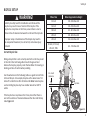 7
7
-
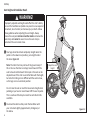 8
8
-
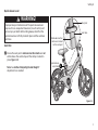 9
9
-
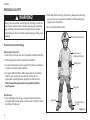 10
10
-
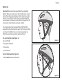 11
11
-
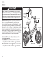 12
12
-
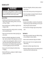 13
13
-
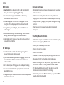 14
14
-
 15
15
-
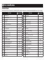 16
16
-
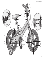 17
17
-
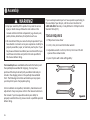 18
18
-
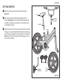 19
19
-
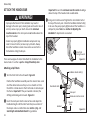 20
20
-
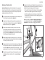 21
21
-
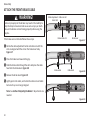 22
22
-
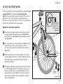 23
23
-
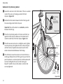 24
24
-
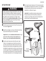 25
25
-
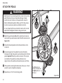 26
26
-
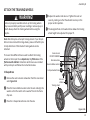 27
27
-
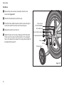 28
28
-
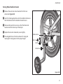 29
29
-
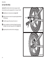 30
30
-
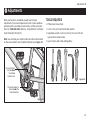 31
31
-
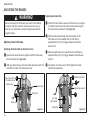 32
32
-
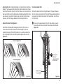 33
33
-
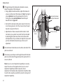 34
34
-
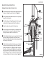 35
35
-
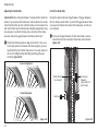 36
36
-
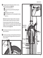 37
37
-
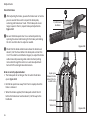 38
38
-
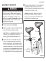 39
39
-
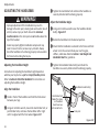 40
40
-
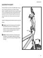 41
41
-
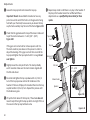 42
42
-
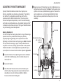 43
43
-
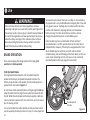 44
44
-
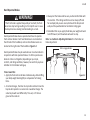 45
45
-
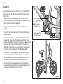 46
46
-
 47
47
-
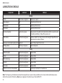 48
48
-
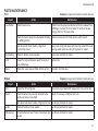 49
49
-
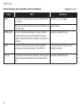 50
50
-
 51
51
-
 52
52
-
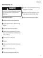 53
53
-
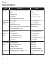 54
54
-
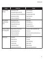 55
55
-
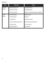 56
56
-
 57
57
-
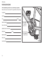 58
58
-
 59
59
-
 60
60
-
 61
61
-
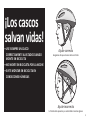 62
62
-
 63
63
-
 64
64
-
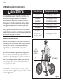 65
65
-
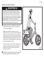 66
66
-
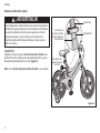 67
67
-
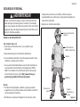 68
68
-
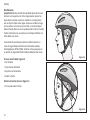 69
69
-
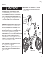 70
70
-
 71
71
-
 72
72
-
 73
73
-
 74
74
-
 75
75
-
 76
76
-
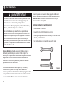 77
77
-
 78
78
-
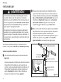 79
79
-
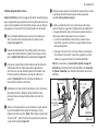 80
80
-
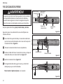 81
81
-
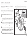 82
82
-
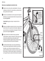 83
83
-
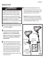 84
84
-
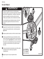 85
85
-
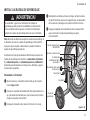 86
86
-
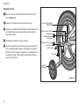 87
87
-
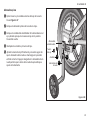 88
88
-
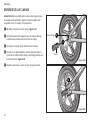 89
89
-
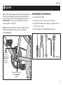 90
90
-
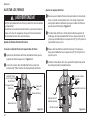 91
91
-
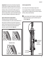 92
92
-
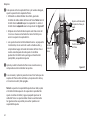 93
93
-
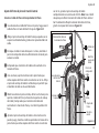 94
94
-
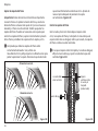 95
95
-
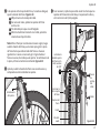 96
96
-
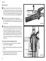 97
97
-
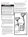 98
98
-
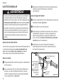 99
99
-
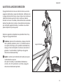 100
100
-
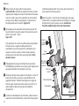 101
101
-
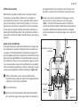 102
102
-
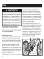 103
103
-
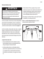 104
104
-
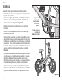 105
105
-
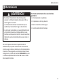 106
106
-
 107
107
-
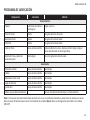 108
108
-
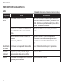 109
109
-
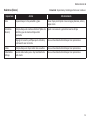 110
110
-
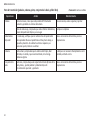 111
111
-
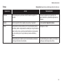 112
112
-
 113
113
-
 114
114
-
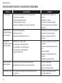 115
115
-
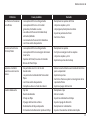 116
116
-
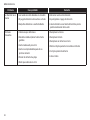 117
117
-
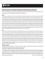 118
118
-
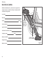 119
119
-
 120
120
-
 121
121


PJMASKS R0402TR Instrucciones de operación
- Categoría
- Bicicletas
- Tipo
- Instrucciones de operación
- Este manual también es adecuado para
en otros idiomas
Otros documentos
-
Schwinn S1671TRB Instrucciones de operación
-
 Schwinn Bicycles Full Suspension Bicycle El manual del propietario
-
 Schwinn Bicycles Hybrid Bicycle El manual del propietario
-
 Schwinn Bicycles Mountain Bicycle El manual del propietario
-
 Schwinn Bicycles BMX Bicycle El manual del propietario
-
 Schwinn Bicycles Cruiser Bicycle El manual del propietario
-
-
-
Momentum Bicycle El manual del propietario
-
Giant Liv Bicycle El manual del propietario


