Hitachi C 6 Handling Instructions Manual
- Categoría
- Herramientas eléctricas
- Tipo
- Handling Instructions Manual
Este manual también es adecuado para

Circular Saw
Sierra Circular
원형톱
C 6
•
C 7
HANDLING INSTRUCTIONS
INSTRUCCIONES DE MANEJO
취급 설명서
Read through carefully and understand these instructions before use.
Leer cuidadosamente y comprender estas instrucciones antes del uso.
본 설명서를 자세히 읽고 내용을 숙지한 뒤 제품을 사용하십시오.
C 7

1
12
34
56
7
1
3
4
2
e
r
7
8
9
5
6
!
@
0
#
$
%
^
&
%
*
(
)
q
w

2
English Español
한국어
1
Lumber Madera útil
목재
2
Base Base
베이스
3
Work bench Banco de trabajo
작업대
4
Saw blade Cuchilla de sierra
톱날
5
Base Base
베이스
6
Wing nut Tuerca de mariposa
윙 너트
7
Cutting position at
45°
Posición de corte 45°
45° 절단 위치
45
8
Wing bolt Perno de mariposa
윙 볼트
9
Scale Escala
스케일
0
Guide piece
Pieza guía
가이드 피스
!
Front scale at 45°
incline
Escala frontal com
45° de inclinación
45° 기울기의
프론트 스케일
45
@
Front scale when not
inclined
Escala frontal sin niet
hellend zaagblad
inclinación
기울지 않았을 때의
프론트 스케일
#
Guide Guía
가이드
$
Depress the lock
lever
Apretar
잠금 레버를 누름
%
Bolt Perno
볼트
^
Loosen Soltar
풀다
&
Tighten Apretar
죄다
*
Washer (B) Arandela (B)
와셔 (B)
(B)
(
Saw blade Cuchilla de sierra
톱날
)
Washer (A) Arandela (A)
와셔 (A)
(A)
q
Distance piece Pieza distanciadora
디스턴스 피스
w
Spindle Eje
스핀들
e
Wear limit Límit de uso
마모 한도
r
No. of carbon brush
No. de carbón de
contacto
카본 브러시 번호

3
English
GENERAL SAFETY RULES
WARNING!
Read all instructions
Failure to follow all instructions listed below may result in
electric shock, fi re and/or serious injury.
The term “power tool” in all of the warnings listed below
refers to your mains operated (corded) power tool or battery
operated (cordless) power tool.
SAVE THESE INSTRUCTIONS
1) Work area
a) Keep work area clean and well lit.
Cluttered and dark areas invite accidents.
b) Do not operate power tools in explosive
atmospheres, such as in the presence of
fl ammable liquids, gases or dust.
Power tools create sparks which may ignite the dust
of fumes.
c) Keep children and bystanders away while
operating a power tool.
Distractions can cause you to lose control.
2) Electrical safety
a) Power tool plugs must match the outlet.
Never modify the plug in any way.
Do not use any adapter plugs with earthed
(grounded) power tools.
Unmodifi ed plugs and matching outlets will reduce
risk of electric shock.
b) Avoid body contact with earthed or grounded
surfaces such as pipes, radiators, ranges and
refrigerators.
There is an increased risk of electric shock if your
body is earthed or grounded.
c) Do not expose
power tools to rain or wet
conditions.
Water entering a power tool will increase the risk
of electric shock.
d) Do not abuse the cord. Never use the cord for
carrying, pulling or unplugging the power tool.
Keep cord away from heat, oil, sharp edges or
moving parts.
Damaged or entangled cords increase the risk of
electric shock.
e) When operating a power tool outdoors, use an
extension cord suitable for
outdoor use.
Use of a cord suitable for outdoor use reduces
the risk of electric shock.
3) Personal safety
a) Stay alert, watch what you are doing and use
common sense when operating a power tool.
Do not use a power tool while you are tired
or under the infl uence of drugs, alcohol or
medication.
A moment of inattention while operating power
tools may result in serious personal injury.
b) Use safety equipment. Always wear eye
protection.
Safety equipment such as dust mask, non-skid
safety shoes, hard hat, or hearing protection used for
appropriate conditions will reduce personal injuries.
c) Avoid accidental starting. Ensure the switch is in
the off position before plugging in.
Carrying power tools with your fi nger on the
switch or plugging in power tools that have the switch
on invites accidents.
d) Remove any adjusting key or wrench before
turning the power tool on.
A wrench or a key left attached to a rotating part
of the power tool may result in personal injury.
e) Do not overreach. Keep proper footing and
balance at all times.
This enables better control of the power tool in
unexpected situations.
f) Dress properly. Do not wear
loose clothing or
jewellery. Keep your hair, clothing and gloves
away from moving parts.
Loose clothes, jewellery or long hair can be caught in
moving parts.
g) If devices are provided for the connection of
dust extraction and collection facilities, ensure
these are connected and properly used.
Use of these devices can reduce dust related
hazards.
4) Power tool use and care
a) Do not force the power tool. Use the
correct
power tool for your application.
The correct power tool will do the job better and safer
at the rate for which it was designed.
b) Do not use the power tool if the switch does not
turn it on and off .
Any power tool that cannot be controlled with the
switch is dangerous and must be repaired.
c) Disconnect the plug from the power source
before making any adjustments, changing
accessories, or storing power tools.
Such preventive safety measures reduce the risk
of starting the power tool accidentally.
d) Store idle power tools out of
the reach of children
and do not allow persons unfamiliar with the
power tool or these instructions to operate the
power tool.
Power tools are dangerous in the hands of
untrained users.
e) Maintain power tools. Check for misalignment or
binding of moving parts, breakage of parts and
any other condition that may aff ect the power
tools operation.
If damaged, have the power tool repaired before
use.
Many accidents are caused by poorly maintained
power tools.
f) Keep cutting tools sharp and clean.
Properly maintained cutting tools with sharp cutting
edges are less likely to bind and are easier to
control.
g) Use the power tool, accessories and tool bits
etc., in accordance with these instructions and
in the manner intended for the particular type
of power tool, taking into account the working
conditions and
the work to be performed.
Use of the power tool for operations diff erent from
intended could result in a hazardous situation.
5) Service
a) Have your power tool serviced by a qualifi ed
repair person using only identical replacement
parts.
This will ensure that the safety of the power tool
is maintained.
PRECAUTION
Keep children and infi rm persons away.
When not in use, tools should be stored out of reach of
children and infi rm
persons.

English
4
SAFETY INSTRUCTIONS FOR ALL SAWS
a) DANGER: Keep hands away from cutting area
and the blade. Keep your second hand on auxiliary
handle, or motor housing.
If both hands are holding the saw, they cannot be cut by
the blade.
b) Do not reach underneath the workpiece.
The guard cannot protect you from the blade below the
workpiece.
c) Adjust the cutting depth to the thickness of the
workpiece.
Less than a full tooth of the blade teeth should be visible
below the workpiece.
d) Never hold piece being cut in your hands or across
your leg. Secure the workpiece to a stable platform.
It is important to support the work properly to minimize
body exposure, blade binding, or loss of control.
e) Hold power tool by insulated gripping surfaces
when performing an operation where the cutting
tool may contact hidden wiring or its own cord.
Contact with a “live” wire will also make exposed metal
parts of the power tool “live” and shock the operator.
f) When ripping always use a rip fence or straight
edge guide.
This improves the accuracy of cut and reduces the
chance of blade binding.
g) Always use
blades with correct size and shape
(diamond versus round) of arbour holes.
Blades that do not match the mounting hardware of the
saw will run eccentrically, causing loss of control.
h) Never use damaged or incorrect blade washers or
bolt.
The blade washers and bolt were specially designed
for your saw, for optimum performance and safety of
operation.
FURTHER SAFETY INSTRUCTIONS FOR ALL
SAWS
Causes and operator prevention of kickback:
– kickback is a sudden reaction to a pinched, bound or
misaligned saw blade, causing an uncontrolled saw to lift
up and out of the workpiece toward the operator;
– when the blade is pinched or bound tightly by the kerf
closing down, the blade stalls
and the motor reaction
drives the unit rapidly back toward the operator;
– if the blade becomes twisted or misaligned in the cut, the
teeth at the back edge of the blade can dig into the top
surface of the wood causing the blade to climb out of the
kerf and
jump back toward the operator.
Kickback is the result of saw misuse and/or incorrect
operating procedures or conditions and can be avoided by
taking proper precautions as given below.
a) Maintain a fi rm grip with both hands on the saw and
position your arms to resist kickback forces.
Position your body
to either side of the blade, but
not in line with the blade.
Kickback could cause the saw to jump backwards, but
kickback forces can be controlled by the operator, if
proper precautions are taken.
b) When blade is binding, or when interrupting a cut
for any reason, release the trigger and hold the saw
motionless in the material until the blade comes to a
complete stop.
Never attempt to remove the saw from the work or
pull the saw backward while the blade is in
motion
or kickback may occur.
Investigate and take corrective actions to eliminate the
cause of blade binding.
c) When restarting a saw in the workpiece, centre the
saw blade in the kerf and check that saw teeth are
not engaged into the material.
If saw blade is binding, it may walk up or kickback from
the workpiece as the saw is restarted.
d) Support large panels to minimise the risk of blade
pinching and kickback.
Large panels tend to sag under their own weight.
Supports must be placed under the panel on both sides,
near the line of cut and near the edge of the panel.
e) Do not use dull
or damaged blades.
Unsharpened or improperly set blades produce narrow
kerf causing excessive friction, blade binding and
kickback.
f) Blade depth and bevel adjusting locking levers must
be tight and secure before making cut.
If blade adjustment shifts while cutting, it may cause
binding and kickback.
g) Use extra caution when making a “plunge cut” into
existing walls or other blind areas.
The protruding blade may cut objects that can cause
kickback.
SAFETY INSTRUCTIONS FOR SAWS WITH
PENDULUM GUARD OR TOW GUARD
a) Check lower guard for proper closing before each
use. Do not operate the saw if lower guard does not
move freely and close instantly. Never clamp or tie
the lower guard into the open position.
If saw is accidentally dropped, lower guard may be bent.
Raise the lower guard with the retracting handle and
make sure it moves freely and does not touch the blade
or any other part, in all angles and depths of cut.
b) Check the operation of the lower guard spring. If
the guard and the
spring are not operating properly,
they must be serviced before use.
Lower guard may operate sluggishly due to damaged
parts, gummy deposits, or a build-up of debris.
c) Lower guard should be retracted manually only for
special cuts such as “plunge cuts” and “compound
cuts”. Raise lower guard by retracting handle and as
soon as blade enters the material, the lower guard
must be released.
For all other sawing, the lower guard should operate
automatically.
d)
Always observe that the lower guard is covering the
blade before placing saw down on bench or fl oor.
An unprotected, coasting blade will cause the saw to
walk backwards, cutting whatever is in its path.
Be aware of the time it takes for the blade to stop after
switch is released.

5
English
PRECAUTIONS ON USING CIRCULAR SAW
1. Proceed with cutting operation when full speed has been
reached.
2. Never use the circular saw with its lower guard fi xed
open.
3. Ascertain that lower guard moves smoothly.
4. Never lay down the circular saw while the saw blade is
revolving.
5. Turn OFF the switch immediately when
a fault occurs.
6. Never operate circular saw with its saw blade turned
upward.
7. Cutting glass fi ber is not recommended.
8. Do not use the saw blade of which the diameter at the
end of the teeth is less than 134 mm (C6) or 162 mm
(C7).
9. Always keep
the saw blade sharp.
10. Ascertain that the workpiece is free of foreign matter
such as nails.
11. Exercise care to position the circular saw at a safe, stable
spot when sawing.
SPECIFICATIONS
Model C6 C7
Voltage* (110 V, 115 V, 120 V, 127 V, 220 V, 230 V, 240 V)
Power Input* 670 W 1050 W
Max. Cutting Depth 55 mm 65 mm
Saw Blade: external diam.
160 mm 185 mm
thickness 1.05 mm 1.25 mm
internal diam. 19 mm 19 mm
No-load Speed 4700 / min
Weight (without cord) 3.1 kg 3.9 kg
*Be sure to check the nameplate on product as it is subject to change by areas.
STANDARD ACCESSORIES
(1) Combination Saw Blade (Monted to the tool) ................1
(2) Box Wrench ..................................................................1
(3) Guide .... .......................................................................1
Standard accessories are subject to change without notice.
OPTIONAL ACCESSORIES (sold separately)
1. Side Handle Set (for only C7)
1 Side Handle ..................................................................1
2 Plate ..........................................................................1
3 Spring Lock Washer (for M10) ......................................1
4 M10 Hexagon Cap Nut .................................................1
5 M5×12
⊕ Hd. Machine Screw .....................................2
(w/washer)
(Attached condition)
Combination Saw Blade
2. Combination Saw Blade (for only C7)
Application: Cutting various types of wood
Size:
185 mm external diam. × 1.25 mm thickness

English
6
Planer Saw Blade
3. Planer Saw Blade
Applications: For applications requiring an especially fi ne surface after cutting
After cutting the surface will be smooth and fi ne, and it is possible to perform
fi nishing highly accurately.
Size:
160 mm external diam. × 1.05 mm thickness ............................................ C6
185 mm external diam. × 1.25 mm thickness
............................................ C7
Saw Blade for Plastics
4. Saw Blade for Plastics
Applications: Cutting various decorative boards, thin plastic boards, and new types of
building material which are soft
There is a fi ne surface after cutting, and end-breaking and cracking will not
occur.
Size:
160 mm external diam. × 1.05 mm thickness ............................................ C6
185 mm
external diam. × 1.25 mm thickness ............................................ C7
CAUTION
In the case of both the Planer Saw Blade and the Saw Blade for Plastics, the saw teeth
maybe sharpened, but do not attempt to the saw blade.
Rip Saw Blade
5. Rip Saw Blade
Applications: Suitable for roughing or ripping lumber
Demonstrates good operating effi ciency
Size:
160 mm external diam. × 1.05 mm thickness ............................................ C6
185 mm external diam. × 1.25 mm thickness ............................................ C7
Carbide-Tipped Saw Blade
6. Carbide-Tipped Saw Blade (for only C7)
Application: Cutting various types of wood
Size:
185 mm external diam. × 1.4 mm thickness
Groove Cutter
7. Groove Cutter (for both C6 and C7)
Application: Grooving various types of wood
Cutting depth:
0 – 15 mm
Size:
100 mm external diam. × 9 mm width
CAUTION
When using a groove cutter, use a distance piece sold separately. (Code No. 957074)
Washer (B)
Bolt
Groove Cutter
Spindle
Distance
Piece
Washer (B)
Bolt
Groove Cutter
Spindle
Distance
Piece
Saw Blade for Aluminum
8. Saw Blade for Aluminum
Application: Cutting thin aluminum sheets
Size:
160 mm external diam. × 1.25 mm thickness ............................................ C6
185 mm external diam. × 1.25 mm thickness ............................................ C7

7
English
Super Polynet Saw
9. Super Polynet Saw (for both C6 and C7)
(Label color ......................................... yellowish green)
Application: Cutting nonmetallic materials such as slate, gypsum board, cemented
excelsior board, etc.
Size:
150 mm external diam. × 1.7 mm thickness
Contact Guard
Bench
Stand
10. Circular Saw Bench Stand
(with Contact Guard) Model: PS7-BS3 (for C6 and C7)
For use in stationary operations with circular saw
11. Contact Guard
Model: PS7-S3 (for PS7-BS3)
Safer operations can be conducted with the circular saw bench stand in a stationary
condition.
Optional accessories are subject to change without
notice.
APPLICATION
○ Cutting various types of wood
○ Grooving various types of wood (use a groove cutter)
○ Cutting various decorative boards, thin plastic boards,
and new types of building materials which are soft (use
a saw blade for plastics)
○ Cutting thin aluminum sheets (use a saw blade for
aluminum)
○ Cutting nonmetallic
materials such as slate, gypsum
board, cemented excelsior board, etc. (use a super
polynet saw)
PRIOR TO OPERATION
1. Power source
Ensure that the power source to be utilized conforms
to the power requirements specifi ed on the product
nameplate.
2. Grounding
This tool should be grounded while in use to protect the
operator from electric shock. The tool is equipped with a
three conductor cord and grounding type
plug to fi t the
proper grounding type receptacle. The green (or green
and yellow) conductor in the cord is the grounding wire.
Never connect the green (or green and yellow) wire to a
live terminal.
3. Power switch
Ensure that the power switch is in the OFF position. If the
plug
is connected to a receptacle while the power switch
is in the ON position, the power tool will start operating
immediately, inviting serious accident.
4. Extension cord
When the work area is removed from the power source.
Use an extension cord of suffi cient thickness and rated
capacity. The extension cord
should be kept as short as
practicable.
5. Prepare a wooden workstand (Fig. 1)
Since the saw blade will extend beyond the lower
surface of the lumber, place the lumber on a workstand
when cutting. If a square block is utilized as a workstand,
select level ground to ensure it is
properly stabilized. An
unstable workstand will result in hazardous operarion.
CAUTION
To avoid possible accident, always ensure that the portion
of lumber remaining after cutting is securely anchored or
held in position.
ADJUSTING THE POWER TOOL PRIOR TO USE
1. Adjusting the cutting depth
The cutting depth can be adjusted by moving the base
after loosening its wing nut (Fig. 2).
CAUTION
Should this wing nut remain loosened, it will create a very
hazardous situation. Always thoroughly clamp it.
2. Adjusting the angle of inclination
By loosening the wing
bolt at the scale, the saw blade
can be tilted up to maximum angle of 45° against the
base (Fig. 3).
The angle of inclination can also be regulated by
loosening the wing bolt at the scale (Fig. 3).
CAUTION
It is very hazardous to allow this wing bolt to
remain
loosened. Always thoroughly clamp it.
3. Regulating the guide
The cutting position can be regulated by moving the
guide to the left or right after loosening its wing bolt.
The guide can be mounted on either the left or the right
side.
CUTTING PROCEDURES
1. Place the saw body (base) on the lumber, and align the
cutting line with the saw blade at the guide piece (Fig. 4).
2. Turn ON the switch before the saw blade contacts the
lumber. The switch is turned ON when the trigger is
squeezed, and turned OFF when
the trigger is released.
CAUTIONS
○ Before starting to saw, confi rm that the saw blade has
attained full-speed revolution.
○ Should the saw blade stop or make an abnormal noise
while operating, promptly turn OFF the switch.
○ Always take care in preventing the power cord from
coming near to the revolving
saw blade.
○ Using the circular saw with the saw blade facing upwards
or sideways is very hazardous. Such uncommon
applications should be avoided.
○ When cutting materials, always wear protective glasses.
○ When fi nished with a job, pull out the plug from the
receptacle.

English
8
○ Replacing carbon brushes
Disassemble the brush cap with a slotted-head
screwdriver. The carbon brush can then be easily
removed.
5. Inspecting lower guard functioning and its
maintenance
Carefully maintain the lower guard so that it remains
capable of smoothly functioning. Completely remove
sawdust deposited around the rotary portion of the
lower
guard, and then apply spindle oil to its siding section to
attain better functioning.
6. Service parts list
A: Item No.
B: Code No.
C: No. Used
D: Remarks
CAUTION
Repair, modifi cation and inspection of Hitachi Power
Tools must be carried out by a Hitachi Authorized Service
Center.
This Parts List will
be helpful if presented with the tool to
the Hitachi Authorized Service Center when requesting
repair or other maintenance.
In the operation and maintenance of power tools, the
safety regulations and standards prescribed in each
country must be observed.
MODIFICATIONS
Hitachi Power Tools are constantly being improved
and modifi ed to
incorporate the latest technological
advancements.
Accordingly, some parts (i.e. code numbers and/or
design) may be changed without prior notice.
NOTE
Due to HITACHI’s continuing program of research and
development, the specifi cations herein are subject to change
without prior notice.
MOUNTING AND DISMOUNTING THE SAW
BLADE
CAUTION
To avoid serious accident, ensure the switch is in the OFF
position, and the power source is disconnected.
1. Dismounting the saw blade
(1) Set the cutting depth to maximum and place the
circular saw in a rigid position (Fig. 5).
(2) Keeping the lock lever depressed, carefully turn the
bolt
with the supplied box wrench.
(3) When the saw shaft is fi xed, turn the box wrench
counterclockwise to remove bolt and washer (B).
(4) While gripping the lower guard knob, retract the lower
guard into the saw cover and take out the saw blade.
2. Mounting the saw blade
(1) Install the
saw blade in the reverse order to removal.
(2) Wipe off the swarf from the spindle, washer, etc.
(3) When installing a saw blade with a hole diameter of
19 mm, such as the HITACHI genuine part, install
washer (A) so that the deeper groove faces toward
the saw blade. When
installing a saw blade with a
hole diameter of 20 mm, install washer (A) so that the
shallow groove faces toward the saw blade. In both
cases, install washer (B) so that the groove faces
toward the saw blade. (Fig. 6).
CAUTION
When reinstalling the saw blade, do not forget
to
install the distance piece. The size of the distance
piece diff ers from that of the optionally available one
(refer to 7. Groove cutter, page 6). Always install the
correct distance washer.
(4) The saw blade should be installed so that the arrow
on the saw blade is aligned
with the arrow on the saw
cover.
(5) Tighten the bolt securely.
CAUTIONS
○ If a box wrench other than the one supplied is used,
the bolt cannot be tightened correctly. Always use the
supplied box wrench.
○ Before connecting the power cord, check that the lock
lever is returned to its original
position and the saw blade
rotates smoothly.
MAINTENANCE AND INSPECTION
1. Inspecting the saw blade
Since use of a dull saw blade will cause motor
malfunctioning and degraded effi ciently, whet it or
replace with a new one without delay when abrasion is
noted.
2. Inspecting the mounting screws
Regularly inspect all mounting screws and ensure that
they are properly tightened.
Should any of the screws be
loose, retighten them immediately. Failure to do so could
result in serious hazard.
3. Maintenance of the motor
The motor unit winding is the very “heart” of the power
tool. Exercise due care to ensure the winding does not
become damaged and/or wet with oil
or water.
4. Inspecting the carbon brushes (Fig. 7)
The motor employs carbon brushes which are
consumable parts. Since an excessively worn carbon
brush could result in motor trouble, replace the carbon
brushes with new ones which having the same carbon
brush No. shown in the fi gure when they become worn
to
or near the “wear limit”. In addition, always keep carbon
brushes clean and ensure that they slide freely within the
brush holders.

9
Español
NORMAS GENERALES DE SEGURIDA
¡ADVERTENCIA!
Lea todas las instrucciones
Si no se siguen las instrucciones de abajo podría producirse
una descarga eléctrica, un incendio y/o daños graves.
El término “herramienta eléctrica” en todas las advertencias
indicadas a continuación hace referencia a la herramienta
eléctrica que funciona con la red de suministro (con cable) o
a la herramienta eléctrica que funciona con pilas (sin cable).
CONSERVE ESTAS INSTRUCCIONES
1) Área de trabajo
a) Mantenga la zona de trabajo limpia y bien
iluminada.
Las zonas desordenadas y oscuras pueden provocar
accidentes.
b) No utilice las herramientas eléctricas en entornos
explosivos como, por ejemplo, en presencia de
líquidos infl amables, gases o polvo.
Las herramientas eléctricas crean chispas que
pueden hacer que el polvo desprenda humo.
c) Mantenga a los niños y transeúntes alejados
cuando utilice una herramienta eléctrica.
Las distracciones pueden hacer que pierda el
control.
2) Seguridad eléctrica
a) Los enchufes de las herramientas eléctricas
tienen que ser adecuados a la toma de
corriente.
No modifi que el enchufe.
No utilice enchufes adaptadores con
herramientas eléctricas conectadas a tierra.
Si no se modifi can los enchufes y se utilizan tomas
de corriente adecuadas se reducirá el riesgo de
descarga eléctrica.
b) Evite el contacto corporal con superfi cies
conectadas
a tierra como tuberías, radiadores y
frigorífi cos.
Hay mayor riesgo de descarga eléctrica si su cuerpo
está en contacto con el suelo.
c) No exponga las herramientas eléctricas a la
lluvia o a la humedad.
La entrada de agua en una herramienta eléctrica
aumentará el riesgo de descarga eléctrica.
d) No utilice el cable incorrectamente. No utilice el
cable para transportar, tirar de la herramienta
eléctrica o desenchufarla.
Mantenga el cable alejado del calor, del aceite,
de bordes afi lados o piezas móviles.
Los cables dañados o enredados aumentan el riesgo
de descarga eléctrica.
e) Cuando utilice una herramienta eléctrica al aire
libre, utilice un cable prolongador adecuado
para utilizarse al aire libre.
La utilización de un cable adecuado para usarse al
aire libre reduce el riesgo de descarga eléctrica.
3) Seguridad personal
a) Esté atento, preste atención a lo que hace y
utilice el sentido común cuando utilice una
herramienta eléctrica.
No utilice
una herramienta eléctrica cuando esté
cansado o esté bajo la infl uencia de drogas,
alcohol o medicación.
La distracción momentánea cuando utiliza
herramientas eléctricas puede dar lugar a importantes
daños personales.
b) Utilice equipo de seguridad. Utilice siempre una
protección ocular.
El equipo de seguridad como máscara para el
polvo, zapatos de seguridad antideslizantes, casco
o protección para oídos utilizado para condiciones
adecuadas reducirá los daños personales.
c) Evite un inicio accidental. Asegúrese de que el
interruptor está en “off ” antes de enchufarlo.
El transporte de herramientas eléctricas con el
dedo en el interruptor o el enchufe de herramientas
eléctricas con el interruptor encendido puede
provocar accidentes.
d) Retire las llaves
de ajuste antes de encender la
herramienta eléctrica.
Si se deja una llave en una pieza giratoria de la
herramienta eléctrica podrían producirse daños
personales.
e) No se extralimite. Mantenga un equilibrio
adecuado en todo momento.
Esto permite un mayor control de la herramienta
eléctrica en situaciones inesperadas.
f) Vístase adecuadamente. No lleve prendas
sueltas o joyas. Mantenga el pelo, la ropa y los
guantes alejados de las piezas móviles.
La ropa suelta, las joyas y el pelo largo pueden
pillarse en las piezas móviles.
g) Si se proporcionan dispositivos para la conexión
de extracción de polvo e instalaciones de
recogida, asegúrese de que están conectados y
se utilizan adecuadamente.
La utilización de estos dispositivos puede reducir los
riesgos relacionados con el polvo.
4) Utilización y mantenimiento de las herramientas
eléctricas
a) No fuerce la herramienta eléctrica. Utilice
la herramienta eléctrica correcta para su
aplicación.
La herramienta eléctrica correcta trabajará mejor y
de forma más segura si se utiliza a la velocidad para
la que fue diseñada.
b) No utilice la herramienta elétrica si el interruptor
no la
enciende y apaga.
Las herramientas elétricas que no pueden controlarse
con el interruptor son peligrosas y deben repararse.
c) Desconecte el enchufe de la fuente eléctrica
antes de hacer ajustes, cambiar accesorios o
almacenar herramientas eléctricas.
Estas medidas de seguridad preventivas reducen el
riesgo de que la herramienta eléctrica se ponga en
marcha accidentalmente.
d) Guarde las herramientas eléctricas que no se
utilicen para que no las cojan los niños y no
permita que utilicen las herramientas eléctricas
personas no familiarizadas con las
mismas o
con estas instrucciones.
Las herramientas eléctricas son peligrosas si son
utilizadas por usuarios sin formación.
e) Mantenimiento de las herramientas eléctricas.
Compruebe si las piezas móviles están mal
alineadas o unidas, si hay alguna pieza rota u otra
condición que pudiera afectar al funcionamiento
de las herramientas eléctricas.
Si la herramienta eléctrica está dañada, llévela a
reparar antes de utilizarla.
Se producen muchos accidentes por no realizar
un mantenimiento correcto de las herramientas
eléctricas.
f) Mantenga las herramientas de corte afi ladas y
limpias.

Español
10
Las herramientas de corte correctamente mantenidas
con los bordes de corte afi lados son más fáciles de
controlar.
g) Utilice la herramienta eléctrica, los accesorios
y las brocas de la herramienta, etc., de acuerdo
con estas instrucciones y de la manera adecuada
para el tipo de herramienta eléctrica, teniendo
en cuenta las condiciones laborales y el trabajo
que se va a realizar.
La utilización de la herramienta eléctrica para
operaciones diferentes a pretendidas podría dar
lugar a una situación peligrosa.
5) Revisión
a) Lleve
su herramienta a que la revise un experto
cualifi cado que utilice sólo piezas de repuesto
idénticas.
Esto garantizará el mantenimiento de la seguridad de
la herramienta eléctrica.
PRECAUCIÓN
Mantenga a los niños y a las personas enfermas
alejadas.
Cuando no se utilicen, las herramientas deben
almacenarse fuera del alcance de los niños y de las
personas enfermas.
INSTRUCCIONES DE SEGURIDAD PARA TODAS
LAS SIERRAS
a) PELIGRO: Mantenga las manos alejadas del área
de corte y de la hoja. Mantenga la otra mano en el
mango auxiliar o en la cubierta del motor.
Si sujeta las sierra con las dos manos, no se cortará con
la hoja.
b) No se coloque debajo de la pieza de trabajo.
El protector no puede protegerle de la hoja debajo de la
pieza de trabajo.
c) Ajuste la profundidad de corte al grosor de la pieza
de
trabajo.
Debajo de la pieza de trabajo sólo debe quedar visible
menos de un diente completo de la hoja.
d) No sujete nunca la pieza que está cortando con las
manos o sobre una pierna. Fije la pieza de trabajo a
una plataforma estable.
Es importante que apoye la pieza de trabajo de forma
adecuada para evitar que su cuerpo quede expuesto a la
sierra, que la hoja se quede atascada o que se pierda el
control.
e) Sujete la herramienta eléctrica por las superfi cies
de sujeción aisladas cuando realice una operación
en la que la herramienta de corte
puede entrar en
contacto con cables ocultos o con su propio cable.
El contacto con un cable “cargado” cargará las piezas
metálicas de la herramienta eléctrica y provocará una
descarga al operador.
f) Cuando realice un corte al hilo, utilice siempre un
tope-guía o una guía de borde recto.
Esto mejorará la precisión del corte y reducirá las
posibilidades de que se atasque la hoja.
g) Utilice siempre hojas con orifi cios de árbol con
el tamaño y la forma correctos (rombo frente a
círculo).
Las hojas que no coincidan con los componentes de
montaje de la sierra no funcionarán correctamente y
pueden provocar una pérdida de control.
h) No utilice nunca arandelas o pernos de hoja
dañados o inadecuados.
Las arandelas y los pernos de la hoja han sido diseñados
especialmente para dicha hoja, con el fi n de garantizar
un rendimiento y seguridad óptimos.
INSTRUCCIONES DE SEGURIDAD
ADICIONALES PARA TODAS LAS SIERRAS
Causas del retroceso y modos en que el operador puede
evitarlo:
– el retroceso es una reacción repentina de la sierra
cuando la hoja se engancha, se atasca o está mal
alineada, lo cual provoca la pérdida de control de la
sierra, que se elevará y se saldrá de la pieza
de trabajo
hacia el operador;
– cuando la hoja se engancha o se atasca por el cierre de
la vía, la hoja se detiene y la reacción del motor hace que
la unidad retroceda rápidamente hacia el operador;
– si la hoja se tuerce o pierde la alineación durante el
corte, los
dientes del borde posterior de la hoja pueden
clavarse en la superfi cie superior de la madera y hacer
que la hoja se salga de la vía y vuelva hacia el operador.
El retroceso es el resultado de un mal uso de la sierra y/o
unos procedimientos o condiciones de funcionamiento
incorrectos y se puede evitar tomando las precauciones
adecuadas que se indican a continuación.
a) Sujete la sierra fi rmemente con las dos manos y
coloque los brazos de tal forma que resistan las
fuerzas de retroceso.
Coloque el cuerpo a uno de los lados de la hoja, no
en línea
con ésta.
El retroceso podría hacer que la sierra salte hacia atrás,
pero las fuerzas de retroceso pueden ser controladas por
el operador, si se toman las precauciones adecuadas.
b) Cuando se atasca la hoja o se interrumpe el corte por
cualquier razón, libere el interruptor de activación y
mantenga la sierra sin moverla en el material hasta
que ésta se detenga por completo.
No intente extraer la sierra de la pieza de trabajo
ni tire de
ella hacia atrás mientras la hoja está
en movimiento, ya que puede producirse un
retroceso.
Investigue y tome las medidas adecuadas para eliminar
la causa del atascamiento de la hoja.
c) Cuando vuelva a poner en marcha la sierra en la
pieza de trabajo, centre la hoja de la sierra en la vía
y compruebe que los dientes no están enganchados
en el material.
Si la hoja de la sierra está atascada, ésta puede saltar o
retroceder de la pieza de trabajo al poner en marcha la
sierra.
d) Utilice soportes adecuados para apoyar los paneles
grandes, con el fi n de minimizar el riesgo de que la
hoja se enganche o se produzca un retroceso.
Los paneles grandes tienden a combarse por su propio
peso. Se deben colocar soportes bajo el panel en ambos
lados, cerca de la línea de corte y cerca del borde del
panel.
e) No utilice hojas melladas o dañadas.
Las hojas no afi ladas o mal ajustadas hacen que una vía
estrecha provoque una fricción excesiva, que se atasque
la hoja y que se produzca un retroceso.
f) La profundidad de la hoja y las palancas de bloqueo
del ajuste del
bisel deben estar bien fi jadas antes de
realizar el corte.
Si el ajuste de la hoja cambia durante el corte, se puede
producir un atasco de la hoja o un retroceso.
g) Tenga especial cuidado cuando realice un “corte
profundo” en paredes existentes o en otras áreas
ciegas.
La hoja que sobresale puede cortar objetos y provocar
un retroceso.

11
Español
INSTRUCCIONES DE SEGURIDAD PARA
SIERRAS CON UN PROTECTOR DE PÉNDULO O
PROTECTOR DE ESTOPA
a) Compruebe que el protector inferior se cierra
correctamente antes de cada uso. No utilice la sierra
si el protector inferior no se mueve libremente o
se cierra de forma instantánea. No sujete ni ate el
protector inferior en la posición de apertura.
Si la sierra se cae de forma accidental, el protector
inferior se puede doblar.
Levante el protector inferior con el mango retráctil
y asegúrese de que se mueve libremente y no toca
la hoja ni ninguna otra pieza, en todos los ángulos y
profundidades de corte.
b) Compruebe el funcionamiento del resorte
del
protector inferior. Si el protector y el resorte no
funcionan correctamente, deben ser reparados
antes de usar la sierra.
El protector inferior puede funcionar lentamente porque
hay alguna pieza dañada, hay restos de pegamento o
existe una acumulación de residuos.
c) El protector inferior sólo se debe retraer
manualmente para realizar cortes especiales, como,
por ejemplo, “punteados” y “cortes compuestos”.
Levante el protector inferior retrayendo el mango y
libere el
protector inferior en cuanto la hoja entre en
contacto con el material.
Para el resto de cortes, el protector debería funcionar
automáticamente.
d) Compruebe siempre que el protector inferior cubre
la hoja antes de colocar la sierra sobre un banco o
sobre el suelo.
El deslizamiento de la hoja sin protección puede hacer
que la sierra se desplace hacia atrás y corte lo que
encuentre a su paso.
Tenga en cuenta el tiempo que tarda la hoja en detenerse
después de accionar el interruptor.
PRECAUCIONES AL UTILIZAR LA SIERRA
CIRCULAR
1. Realice la operación de corte cuando la sierra haya
alcanzado la plena velocidad.
2. Nunca usar la sierra circular con su cubierta de seguridad
fi jada en la posición abierta.
3. Asegurarse de que la cubierta de seguridad se mueva
suave.
4. No coloque en el suelo la sierra circular
mientras la
cuchilla de sierra esté girando.
5. Cuando se produzca algún problema, ponga
inmediatamente en OFF el interruptor.
6. Nunca accionar la sierra circular con la cuchilla vuelta
hacia arriba.
7. No se recomienda cortar fi bra de vidrio.
8. Reemplace la cuchilla de sierra cuando el diámetro de la
misma sea inferior a 134 mm (C6) o 162 mm (C7) en la
base de los dientes.
9. Mantener siempre la cuchilla afi lada.
10. Asegurarse de que la pieza de trabajo esté libre de
cuerpos extraños tales como clavos.
11. Tenga cuidado de colocar la sierra circular en un lugar
seguro
y estable cuando sierre.
ESPECIFICACIONES
Model oC6C7
Voltaje (por áreas)* (110 V, 115 V, 120 V, 127 V, 220 V, 230 V, 240 V)
Acometida* 670 W 1050 W
Profundidad de corte 55 mm 65 mm
Cuchilla de sierra: diámetro exterior
160 mm 185 mm
grosor 1,05 mm 1,25 mm
diámetro interno 19 mm 19 mm
Velocidad de marcha en vacío 4700 / min
Peso (sin cable) 3,1 kg 3,9 kg
* Verifi car indefectiblemente los datos de la placa de características de la máquina, pués varian de acuerdo al país
de
destino.
ACCESORIOS NORMALES
(1) Cuchilla de sierra de combinación
(montada en la herramienta) .........................................1
(2) Llave anular ..................................................................1
(3) Guía ..............................................................................1
Los accesorios normales están sujetos a cambio sin previo
aviso.

Español
12
ACCESORIOS FACULTATIVOS
(de vanta por separado)
1. Juego de manija lateral
(para C7 solamente)
1 Manija lateral .................................................................1
2 Placa .............................................................................1
3 Arandela elástica de seguridad
(para Ml0) .....................................................................1
4 M10 Tuerca ciega hexagonal .......................................1
5 Tornillo de cabeza para máquina M5 × 12 ....................2
(con arandela)
(En condición de fi jado)
Cuchilla de sierra de combinatión
2. Cuchilla de sierra de combinatión (para C7 solamente)
Aplicación: Corte de diversos tipos de madera
Tamaño: 185 mm de diámetro exterior × 1,25 mm de grosor
Cuchilla de sierra aplanadora
3. Cuchilla de sierra aplanadora
Aplicación: Para aplicacion que requieran una superfi cie especialmente lisa después del
corte.
Después del corte, la superfi cie será uniforme y lisa, y será posible realizar
un acabado de gran precisión.
Tamaño: 160 mm de diámetro exterior × 1,05 mm de grosor .................................. C6
185
mm de diámetro exterior × 1,25 mm de grosor .................................. C7
Cuchilla de sierra para
plástico
4. Cuchilla de sierra para plástico
Aplicación: Corte de varios paneles decorativos, paneles fi nos de plástico, y nuevos
tipos de materiales de edifi cación que sean suaves.
Después del corte habrá una superfi cie lisa, y no se producirá rotura ni
rajado al fi nal.
Tamaño: 160 mm
de diámetro exterior × 1,05 mm de grosor .................................. C6
185 mm de diámetro exterior × 1,25 mm de grosor .................................. C7
PRECAUCIÓN
En el caso de la cuchilla de sierra aplanadora y de la cuchilla de sierra para plástico, los
dientes de la sierra pueden afi larse, peso no lo intente con la
cuchilla de sierra.
Cuchilla de sierra para corte
longitudinal
5. Cuchilla de sierra para corte longitudinal
Aplicación: Adecuada para cortar longitudinalmente madera.
Ofrece una buena efi cacia de operación.
Tamaño: 160 mm de diámetro exterior × 1,05 mm de grosor .................................. C6
185 mm de diámetro exterior × 1,25 mm de grosor .................................. C7
Cuchilla de sierra de punta de
carburo
6. Cuchilla de sierra de punta de carburo (para C7 solamente)
Aplicación: Corte de varios tipos de madera.
Tamaño: 185 mm de diámetro exterior × 1,4 mm de grosor

13
Español
Cortador renurado
7. Cortador renurado (para C6 y C7)
Aplicación: Ranurado de diversos tipos de madera.
Profundidad de corte: 0-15 mm
Tamaño: 100 mm de diámetro exterior × 9 mm de anchura
PRECAUCIÓN
Cuando utilice un cortador ranurador, utilice una pieza distanciadora vendida aparte.
(Código núm. 957074)
Arandela (B)
Perno
Cortador ranurador
Eje
Pieza
distanciadora
Hoja de sierra para aluminio
8. Hoja de sierra para aluminio
Aplicación: Corte de planchas fi nas de aluminio.
Tamaño: 160 mm de diámetro exterior × 1,25 mm de grosor .................................. C6
185 mm de diámetro exterior × 1,25 mm de grosor .................................. C7
Sierra Super Polynet
9. Sierra Super Polynet (para C6 y C7)
(Color de le etiqueta ......................... verde amarillento)
Aplicación: Corte de materiales no metálicos tales como pizarra, panel de yeso, panel
excelsior cementado, etc.
Tamaño: 150 mm de diámetro exterior × 1,7 mm de grosor
Protector de
contacto
Soporte
ce banco
10. Soporte de banco de sierra circular
(Con protector de contacto) Modelo: PS7-BS3 (para C6 y C7)
Para utilización en operaciones estacionarias con sierra circular
11. Protector de contacto
Modelo: PS7-S3 (para PS7-BS3)
Con el soporte de banco para sierra circular, podrá realizar operaciones más seguras en
condición estacionaria.
Los accesorios
facultativos están sujetos a cambio sin previo aviso.
APLICACIONES
○ Cortar diversos tipos de madera
○ Ranurado de varios tipos de madera (utilice un cortador
ranurador)
○ Corte de varios paneles decorativos, paneles de plástico
fi no, y nuevos tipos de materiales de edifi cación que
sean suaves (utilice una cuchilla de sierra para plástico)
○ Corte de planchas fi nas de aluminio
(utilice una cuchilla
de sierra para aluminio)
○ Corte de materiales no magnéticos tales como pizarra,
paneles de yeso, paneles excelsior cementados, etc.
(utilice una sierra Super polynet)
ANTES DE LA PUESTA EN MARCHA
1. Alimentación
Asegurarse de que la alimentación de red que ha de
ser utilizada responda a las exigencias de corriente
especifi cadas en la placa de características del
producto.
2. Puesta a tierra
Esta herramienta deberá ponerse a tierra mientras esté
utilizándose para proteger al operador contra descargas
eléctricas. La herramienta
dispone ae un cable con
tres conductores y un enchufe de tipo puesta atierra
que encaja en un tomacorriente de tipo apropiado. El
conductor verde (o verde y amarillo) del cable es el de
conexión a tierra. No conecte nunca el conduc tor verde
(o verde y amarillo) a un terminal
activo.

Español
14
3. Conmutador de alimentación
Asegurarse de que el conmutador de alimentación esté
en la posición OFF (desconectado). Si la clavija está
conectada en la caja del enchufe mientras el conmutador
de alimentación esté en pocisión ON (conectado)
las herramientas eléctricas empezarán a trabajar
inmediatamente, provocando un serio accidente.
4. Cable de
prolongación
Cuando está alejada el área de trabajo de la red de
alimentación, usar un cable de prolongación de un grosor
y potencia nominal sufi ciente. El cable de prolongación
debe ser mantenido lo más corto posible.
5. Preparar un banco de trabajo de madera (Fig. 1)
Como la cuchilla sobresale
debajo de la superfi cie inferior
de la madera útil, situar la madera útil encima de un
banco de trabajo al cortar. Si se usa un bloque cuadrado
como banco de trabajo, seleccionar un fondo liso para
asegurar que sea estable. Un banco de trabajo inestable
tendrá como resultado una operación
peligrosa.
PRECAUCIÓN
Para evitar posibles accidentes, asegurarse siempre
de que la parte de la madera útil restante después de
haberla cortado, quede sujetado fi rmemente y mantenido
en su posición.
AJUSTE DE LA HERRAMIENTA ANTES DE SU
USO
1. Ajuste de la profundidad de corte
Puede ajustar la profundidad de corte moviendo la base
tras afl ojar la palanca (A) (Fig. 2).
PRECAUCIÓN
Es muy peligroso que la palanca (A) se quede fl oja.
Apriétela siempre con fuerza.
2. Ajuste del ángulo de inclinación
Al afl ojar el perno de
mariposa, se puede inclinar la
hoja de la sierra hasta un máximo de 45° contra la base
(Fig. 3).
El ángulo de inclinación también se puede regular
afl ojando la palomilla de la escala (Fig. 3).
PRECAUCIÓN
Es muy peligroso que el perno de mariposa quede fl ojo.
Apriételo siempre con
fuerza.
3. Regulación de la guía
Se puede regular la posición de corte moviendo la guía a
izquierda y derecha tras afl ojar el perno de mariposa.
La guía se puede montar tanto en el lado derecho como
en el izquierdo.
PROCEDIMIENTO DE CORTE
1. Coloque el cuerpo de la sierra (base) sobre la madera y
alinee la línea de corte con la hoja de la sierra en la pieza
quía (Fig. 4).
2. Ponga el interruptor en la posición de encendido (ON)
antes de que la hoja de la sierra entre en contacto
con
la madera. La máquina se pone en marcha al apretar el
disparador y se apaga al soltarlo.
PRECAUCIÓN
○ Antes de empezar a serrar, verifi que que la hoja de
la sierra ha alcanzado las revoluciones de velocidad
máxima.
○ Si la hoja se detiene o emite un ruido extraño durante el
funcionamiento, desconecte de inmediato la máquina.
○ Tenga siempre cuidado de que el cable de alimentación
esté alejado de la hoja de la sierra cuando ésta está en
marcha.
○ Es muy peligroso utilizar la sierra circular con la hoja
apuntando hacia arriba o de lado. Evite estas posiciones
en la
medida de lo posible.
○ Al cortar material, utilice siempre gafas protectoras.
○ Cuando termine de trabajar, desenchufe el cable de la
toma de pared.
MONTAR Y DESMONTAR LA CUCHILLA
PRECAUCIÓN
Para evitar accidentes graves asegurarse de que el
conmutador está la posición OFF (desconectado) y la
acometida de red también esté desconectada.
1. Desmontaje de la cuchilla de sierra
(1) Ajuste la profundidad de corte al máximo y coloque la
sierra circular en posición rígida (Fig. 5).
(2) Manteniendo la palanca
de bloqueo presionada,
gire cuidadosamente el perno con la llave de cubo
suministrada.
(3) Cuando el eje de la sierra quede fi jado, gire la llave
de cubo hacia la izquierda para extraer el perno y la
arandla (B).
(4) Sujetando la perilla de la cubierta de seguridad,
repliegue la cubierta de
seguridad dentro de la
cubierta de la sierra y extraiga la hoja de sierra.
2. Montaje de la cuchilla de sierra
(1) Instale la cuchilla de sierra en orden inverso al de
extracción.
(2) Limpie el serrín del eje, la arandela, etc.
(3) Cuando instale una cuchilla de sierra con un diámetro
de
orifi cio de 19 mm, como una pieza genuina de
HITACHI, instale la arandela (A) de forma que la
ranura más profunda quede encarada hacia la hoja
de sierra. Cuando instale una hoja de sierra con un
diámetro de 20 mm, instale la tuerca (A) de forma
que la ranura
menos profunda quede encarada hacia
la cuchilla de sierra. (Fig. 6).
PRECAUCIÓN
Cuando reinstale la cuchilla de sierra, no se olvide de
instalar la pieza distanciadora. El tamaño de la pieza
distanciadora difi ere de la opcionalmente disponible
(consulte 7. Cortador ranurado, página 13). Instale
siempre la arandela distanciadora
correcta.
(4) La cuchilla de sierra deberá Instalarse de forma que
la fl echa de la misma quede alineada con la fl echa de
la cubierta de la sierra.
(5) Apriete el perno con seguridad.
PRECAUCIÓN
○ Si utiliza una llave de cubo que no sea la suministrada, el
perno no podrá apretarse correctamente. Utilice
siempre
la llave de cubo suministrada.
○ Antes de conectar el cable de alimentación, compruebe
que la palanca de bloqueo esté en su posición original y
de que la hoja de sierra gire uniformemente.
MANTENIMIENTO E INSPECCIÓN
1. Inspeccionar la cuchilla
Como el uso de una cuchilla desgastada disminuye la
efi ciencia y origina posible funcionamiento defectuoso
del motor, afi lar o reemplazar la cuchilla tan pronto como
se note un desgaste.
2. Inspeccionar los tornillos de montaje
Regularmente inspeccionar todos los tornillos de
montaje y asegurarse de
que estén apretados
fi rmemente. Si cualquier tornillo estuviera suelto, volver
a apretarlo inmediatamente. El no hacer esto provocaría
un riesgo serio.
3. Mantenimiento de motor
La unidad de bobinado del motor es el verdadero
“corazón” de las herramientas eléctricas. Prestar el
mayor cuidado a asegurarse de que el bobinado no se
dañe y/o se humedezca con aceite o agua.

15
Español
4. Inspección de escobillas de carbón: (Fig.7)
El motor emplea carbones de contacto que son
partes consumibles. Como un carbón de contacto
excesivamente desgastado podría dar problemas al
motor, reemplazar el carbón de contacto por uno nuevo,
y que tenga el mismo número, como muestra en la fi gura,
cuando se haya
desgastado o esté cerca del límite de
uso. Adicionalmente, mantener siempre los carbones de
contacto limpios y asegurarse de que corran libremente
dentro de los sujetadores de carbón.
○ Reemplazar el carbón de contacto
Quiter la cápsula de carbón con un destornillador con
cabeza pequeña. El carbón de contacto se deja
y luego
se quita con facilidad.
5. Inspección del funcionamiento del protector inferior
y mantenimiento del mismo
Extreme los cuidados del protector inferior para que
pueda funcionar sin problemas. Elimine el serrín
depositado en la parte rotatoria del protector inferior y
aplique aceite del eje en la sección lateral para obtener
un mejor funcionamiento.
6. Lista de repuestos
A: N°. ítem
B: N°. código
C: N°. usado
D: Observaciones
PRECAUCIÓN
La reparación, modifi cación e inspección de las
herramientas eléctricas Hitachi deben ser realizadas por
un Centro de Servicio Autorizado de Hitachi.
Esta lista de repuestos será de utilidad si es presentada
junto con la
herramienta al Centro de Servicio Autorizado
de Hitachi, para solicitar la reparación o cualquier otro
tipo de mantenimiento.
En el manejo y el mantenimiento de las herramientas
eléctricas, se deberán observar las normas y reglamentos
vigentes en cada país.
MODIFICACIONES
Hitachi Power Tools introduce constantemente mejoras
y modifi caciones para incorporar
los últimos avances
tecnológicos.
Por consiguiente, algunas partes (por ejemplo, números
de códigos y/o diseño) pueden ser modifi cadas sin
previo aviso.
OBSERVACIÓN
Debido al programa continuo de investigación y desarrollo
de HITACHI estas especifi caciones están sujetas a cambio
sin previo aviso.

16

17

18

1
2
3
4
5
⊕
19

20

○
○
○
○
○
●
●
●
●
●
●
21

22
●
●
○
注
注

23
한국어
일반적인 안전 수칙
경고!
설명서를 자세히 읽으십시오.
설명서의 내용에 따르지 않을 시에는 감전 사고나 화재가 발
생할 수 있으며 심각한 부상을 입을 수도 있습니다.
아래에 나오는 ‘전동 툴’이란 용어는 플러그를 콘 센트에 연
결해 유선 상태로 사용하는 제품 또는 배터리를 넣어 무선
상태로 사용하는 제품을 가리킵니다.
설명서의 내용을 숙지하십시오.
1) 작업 공간
a) 작업 공간을 깨끗하게 청소하고 조명을 밝게 유지하
십시오.
작업 공간이 정리되어 있지 않거나 어두우면 사고가
날 수 있습니다.
b) 인화성 액체나 기체 또는 먼지 등으로 인해 폭발 위
험이 있는 환경에서는 전동 툴을 사용하지 마십시오.
전동 툴을 사용하다 보면 불꽃이 튀어서 먼지나 기체
에 불이 붙을 수 있습니다.
c) 어린이를 비롯하여 사용자 외에는 작업장소에 접근
하지 못하도록 하십시오.
주의가 산만해지면 문제가 생길 수 있습니다.
2) 전기 사용시 주의사항
a) 전동 툴 플러그와 콘센트가 일치해야 합니다.
플러그를 절대로 변형하지 마십시오.
접지된 전동 툴에는 어댑터 플러그를 사용하지 마십
시오.
플러그를 변형하지 않고 알맞은 콘센트에 꽂아 사용
하면, 감전 위험을 줄일 수 있습니다.
b) 파이프, 라디에이터, 레인지, 냉장고 등 접지된 표면
에 몸이 닿지 않도록 주의하십시오.
작업자의 몸이 접지되면, 감전될 위험이 있습니다.
c) 전동 툴에 비를 맞히거나 젖은 상태로 두지 마십시
오.
물이 들어가면 감전될 위험이 있습니다.
d) 코드를 조심해서 다루십시오. 전동 툴을 들거나 당기
거나 콘센트에서 뽑으려고 할 때 코드를 잡아당기면
안 됩니다.
열, 기름, 날카로운 물건, 움직이는 부품 등으로부터
코드를 보호하십시오.
코드가 파손되거나 엉키면 감전될 위험이 높아집니
다.
e) 실외에서 전동 툴을 사용할 때는 실외 용도에 적합한
연장선을 사용하십시오.
실외 용도에 적합한 코드를 사용해야 감전 위험이 줄
어듭니다.
3) 사용자 주의사항
a) 전동 툴을 사용할 때는 작업에 정신을 집중하고, 상
식의 범위 내에서 사용하십시오.
약물을 복용하거나 알코올을 섭취한 상태 또는 피곤
한 상태에서는 전동 툴을 사용하지 마십시오.
전동 툴을 사용할 때 주의가 흐트러지면 심각한 부상
을 입을 수 있습니다.
b) 안전 장비를 사용하십시오. 항상 눈 보호 장구를 착
용해야 합니다.
먼지 보호 마스크, 미끄럼 방지 신발, 안전모, 청각 보
호 장비 등을 사용하면 부상을 줄일 수 있습니다.
c) 전동 툴이 갑자기 작동되지 않도록 합니다. 플러그를
꽂기 전에 스위치가 ‘OFF’ 위치에 있는지 확인하
십시오.
손가락을 스위치에 접촉한 채 전동 툴을 들거나 스위
치가 켜진 상태로 플러그를 꽂으면 사고가 날 수 있습
니다.
d) 전원을 켜기 전에 조정 키 또는 렌치를 반드시 제거
해야 합니다.
전동 툴의 회전 부위에 키 또는 렌치가 부착되어 있으
면, 부상을 입을 수 있습니다.
e) 작업 대상과의 거리를 잘 조절하십시오. 알맞은 발판
을 사용하고 항상 균형을 잡고 있어야 합니다.
그렇게 하 면 예기치 못한 상황에서도 전동 툴을 잘 다
룰 수 있습니다.
f) 알맞은 복장을 갖추십시오. 헐렁한 옷이나 장신구를
착용하면 안 됩니다. 머리카락, 옷, 장갑 등을 움직이
는 부품으로부터 보호하십시오.
헐렁한 옷이나 장신구, 긴 머리카락이 부품에 딸려 들
어갈 수도 있습니다.
g) 분진 추출 및 집진 장비에 연결할 수 있는 장치가 제
공되는 경우, 그러한 장치가 잘 연결되어 있고 제대로
작동하는지 확인하십시오.
이러한 장치를 사용하면, 먼지와 관련된 사고를 줄일
수 있습니다.
4) 전동 툴 사용 및 관리
a) 전동 툴을 아무 곳에나 사용하지 마십시오. 용도에
알맞은 전동 툴을 사용하십시오.
적절한 전동 툴을 사용하면, 정상 속도로 안전하고 효
과적으로 작업을 수행할 수 있습니다.
b) 스위치를 눌렀을 때 전동 툴이 켜지거나 꺼지지 않으
면 사용하지 마십시오.
스위치로 작동시킬 수 없는 전동 툴은 위험하므로, 수
리를 받아야 합니다.
c) 전동 툴을 조정하거나 부속품을 바꾸거나 보관할 때
는 반드시 전원에서 플러그를 빼야 합니다.
이러한 안전 조치를 취해야 전동 툴이 갑자기 켜지는
위험을 피할 수 있습니다.
d) 사용하지 않는 전동 툴은 어린이의 손이 닿지 않는
곳에 보관하고, 사용법을 잘 모르는 사람이 사용하지
못하도록 하십시오.
전동 툴은 미숙련자가 다루기에는 매우 위험한 물건
입니다.
e) 전동 툴을 잘 관리하십시오. 움직이는 부품이 잘못
결합되어 있거나 꽉 끼어 움직이지 못하게 되어 있지
않은지 점검하십시오. 또한 전동 툴의 작동에 영향을
미칠 수 있는 기타 파손이 없는지 확인하십시오.
파손된 부분이 있는 경우, 사용하기 전에 수리하십시
오.
전동 툴을 제대로 관리하지 못해서 생기는 사고가 많
습니다.
f) 절삭 툴은 날카롭고 청결한 상태로 관리하십시오.
절삭 날을 날카로운 상태로 잘 관리하면, 원활하게
잘 움직이며 다루기도 훨씬 편합니다.
g) 설명서를 참조하여 전동 툴과 부속품, 툴 비트 등을
사용하십시오. 또한 작업 환경과 수행할 작업의 성격
을 고려해서 알맞은 종류의 전동 툴을 선택하고, 적
절한 방식으로 사용하십시오.
원래 목적과 다른 용도로 전동 툴을 사용하면 위험한
사고가 날 수 있습니다.
5) 서비스
a) 자격을 갖춘 전문가에게 서비스를 받고, 항상 원래
부품과 동일한 것으로 교체해야 합니다.
그렇게 하면 전동 툴을 보다 안전하게 사용할 수 있습
니다.
주의사항
어린이나 노약자가 가까이 오지 못하도록 하십시오.
전동 툴을 사용하지 않을 때는 어린이나 노약자의 손이 닿지
않는 곳에 보관해야 합니다.

24
한국어
모든 톱을 위한 안전 지침
a) 위험: 절단 영역 및 날에서 손을 멀리 하십시오. 보조
핸들 또는 모터 하우징에 두 번째 손을 대십시오.
양 손으로 톱을 잡으면 날이 절단할 수 없습니다.
b) 가공물 아래에 손을 뻗지 마십시오.
가드가 가공물 아래에 있는 날로부터 여러분을 보호할
수 없습니다.
c) 절단 깊이를 가공물의 두께에 맞추십시오.
가공물 아래에 날 이빨들의 완전한 이빨 한 개 미만이 보
여야 합니다.
d) 자르고 있는 가공물을 두 손으로 잡거나 다리 사이에 끼
우지 마십시오. 가공물을 안정된 플랫폼에 고정하십시
오.
신체 노출, 날 낌 또는 통제력 상실을 최소화하기 위해 가
공물을 적절하게 받치는 것이 중요합니다.
e) 절단 도구가 숨은 와이어 또는 자신의 코드에 닿을 수 있
는 경우, 작업 수행시 절연된 잡는 표면으로 전동 공구를
잡으십시오.
“통전”된 와이어에 닿으면 전동 공구의 노출된 금속 부
분도 “통전”되어 작업자가 감전될 수 있습니다.
f) 절단시 항상 립 펜스 또는 가장자리가 똑바른 가이드를
사용하십시오.
절단의 정확성이 높아지고 날이 낄 가능성이 낮아집니
다.
g) 항상 올바른 크기 및 모양(마름모꼴 대 원형)의 아버 홀
을 가진 날을 사용하십시오.
톱의 장착 기구와 맞지 않는 날은 가동시 중심을 벗어나
서 통제할 수 없게 됩니다.
h) 손상되거나 부정확한 날 와셔 또는 볼트를 사용하지 마
십시오.
날 와셔 및 볼트는 톱을 위해 그리고 최적 성능 및 안전
작업을 위해 특별 설계되었습니다.
모든 톱을 위한 추가 안전 지침
반동의 원인 및 작업자 예방:
- 반동은 톱날이 끼거나 오정렬되어 갑작스럽게 반응하는
것으로, 통제되지 않은 톱이 가공물에서 빠져 나와 작업
자 쪽으로 튀어 오르는 것입니다.
- 접근하는 절단면에 의해 날이 꽉 끼면 날은 멎고 모터 반
응에 의해 톱이 급격하게 뒤의 작업자 쪽으로 돌진하게
됩니다.
- 절단시 날이 뒤틀리거나 오정렬되면 날의 뒤 가장자리에
있는 이빨이 목재의 상부 표면 안으로 파고 들어가서 날
이 절단면 바깥으로 삐져 나와 작업자 쪽으로 뒤로 튈 수
있습니다.
반동은 톱 오용 및/또는 부정확한 작업 절차 또는 조건의 결
과인데 아래 제시된 적절한 주의를 취함으로써 피할 수 있
습니다.
a) 양 손으로 톱을 계속 단단히 잡고 팔은 반동력에 저항할
수 있는 위치에 둡니다.
신체는 날의 어느 한 쪽에 위치시키되 날과 일직선으로
는 두지 않습니다.
반동으로 인해 톱이 뒤쪽으로 튈 수 있지만 작업자가 적
절한 주의만 취하면 반동력을 억제할 수 있습니다.
b) 어떤 이유로 날이 끼거나 절단이 방해되면 방아쇠를 놓
고 날이 완전히 설 때까지 톱을 목재 속에서 가만히 붙들
고 있습니다.
날이 움직이고 있는 동안 톱을 가공물에서 빼내거나 톱
을 뒤쪽으로 당기려고 하지 마십시오. 반동이 발생할 수
있습니다.
날 낌의 원인을 제거하기 위해 조사한 후 시정 조치를 취
하십시오.
c) 톱을 가공물 속에서 다시 시동할 때는 톱날을 절단 자국
의 중앙에 맞추고 톱 이빨이 목재 안에 물리지 않게 합니
다.
톱날이 낀 경우, 톱을 다시 시동할 때 톱날이 위로 걸어올
라 오거나 가공물로부터 갑자기 되튈 수 있습니다.
d) 날 낌 및 반동의 위험을 최소화하기 위해 큰 패널을 받칩
니다.
큰 패널은 자체 무게로 처지는 경향이 있습니다. 받침은
패널 아래 양 쪽에 절단선 인근 및 패널 가장자리 인근에
놓여야 합니다.
e) 무디거나 손상된 날을 사용하지 마십시오.
날이 날카롭지 않거나 세팅이 부적절하면 절단 자국이
좁아져서 마찰이 과도하게 되고 날이 끼어 반동이 발생
합니다.
f) 절단하기 전에 날 깊이 및 빗각 조절 로킹 레버를 죄어 고
정시켜야 합니다.
절단 중에 날 조정이 움직이면 날이 끼어 반동이 발생할
수 있습니다.
g) 기존 벽 또는 기타 사각 지역 안으로 "플런지 커팅"할 때
특히 주의하십시오.
돌출된 날이 물체를 절단하면서 반동이 발생할 수 있습
니다.
흔들이 가드 또는 견인 가드가 있는 톱을 위한 안
전 지침
a) 매번 사용하기 전에 하부 가드가 적절하게 닫혀 있는지
확인합니다. 하부 가드가 자유롭게 움직이면서 즉각 닫
히지 않으면 톱을 작동하지 마십시오. 하부 가드를 묶거
나 클램프로 고정하여 열리게 하지 마십시오.
톱이 뜻하지 않게 떨어지면 하부 가드가 굽을 수 있습니
다.
끌어당김 핸들로 하부 가드를 올려서 하부 가드가 자유
롭게 움직이면서도 모든 각도 및 깊이의 절단에서 날이나
기타 부품에 닿지 않게 하십시오.
b) 하부 가드 스프링의 작동을 점검하십시오. 가드와 스프
링이 제대로 작동하지 않으면 사용하기 전에 수리해야
합니다.
손상된 부품, 끈적끈적한 침착물 또는 쌓인 부스러기로
인해 하부 가드가 느릿느릿 작동할 수 있습니다.
c) “플런지 커팅” 및 “복합 절단” 같은 특수 절단의 경
우에만 하부 가드를 손으로 집어넣어야 합니다. 끌어당
김 핸들로 하부 가드를 올렸다가 날이 목재에 들어가는
즉시 하부 가드를 놓아야 합니다.
기타 모든 톱질의 경우, 하부 가드는 자동으로 작동되어
야 합니다.
d) 톱을 작업대 또는 바닥에 놓기 전에 하부 가드가 날을 가
리고 있는지 항상 확인하십시오.
날이 가려지지 않은 채 관성으로 움직이는 경우 톱이 뒤
로 움직여서 그 경로에 무엇이 있든 절단할 것입니다.
스위치를 끈 후 날이 정지하는데 걸리는 시간 에 주의하 십
시오.
원형톱 사용시 주의사항
1. 전속력에 도달한 상태에서 절단 작업을 진행하십시오.
2. 하부 보호대가 열린 채로 고정된 상태에서 원형톱을 절대
로 사용하지 마십시오.
3. 하부 보호대가 부드럽게 움직이는지 확인하십시오.
4. 톱날이 회전하는 중에 원형톱을 절대로 내려놓지 마십시
오.
5. 고장이 발생할 경우 스위치를 즉시 끄십시오.
6. 톱날이 위로 회전된 상태에서 원형톱을 절대로 조작하지
마십시오.

25
한국어
사양
모델
C6 C7
전압
*
(110 V, 115 V, 120 V, 127 V, 220 V, 230 V, 240 V)
소비 전력
*
670 W 1050 W
최대 절단 깊이
55 mm 65 mm
톱날: 외경 160 mm 185 mm
두께 1.05 mm 1.25 mm
내경 19 mm 19 mm
무부하 속도 4700 /분
중량 (코드 핸들 제외) 3.1 kg 3.9 kg
* 지역별로 차이가 있을 수 있으므로, 제품 명판의 기재내용을 반드시 확인하십시오.
기본 부속품
(1) 콤비네이션 톱날 (툴에 장착) ............................ 1
(2) 박스 렌치 .................................................. 1
(3) 가이드 ...................................................... 1
기본 부속품은 예고 없이 변경될 수 있습니다.
옵션 부속품 (별도 판매)
1. 사이드 핸들 세트 (C7 전용)
1 사이드 핸들 .................................................. 1
2 플레이트 ...................................................... 1
3 스프링 로크 와셔 (M10용) ................................. 1
4 M10 육각 캡 너트 ........................................... 1
5 M5×12
⊕ 헤드 기계 나사 ................................. 2
(와셔 포함)
(장착 상태)
콤비네이션 톱날
2. 콤비네이션 톱날 (C7 전용)
용도: 다양한 종류의 목재 절단
치수: 185 mm 외경 × 1.25 mm 두께
대패톱날
3. 대패톱날
용도: 절단 후 특히 고운 절단면이 요구되는 작업용.
절단 후 절단면이 곱고 부드러워지며 매우 정확하게 정삭을 수행할 수 있습니다.
치수: 160 mm 외경 × 1.05 mm 두께 ................................................... C6
185 mm 외경 × 1.25 mm 두께 ................................................... C7
7. 유리섬유 절단은 권장되지 않습니다.
8. 톱니 끝의 직경이 134 mm (C6) 또는 162 mm (C7) 미
만인 톱날을 사용하지 마십시오.
9. 항상 톱날을 날카롭게 하십시오.
10. 작업물에 손톱과 같은 이물질이 없는지 확인하십시오.
11. 톱질 중에 원형톱을 안전하고 평평한 위치에 주의하여 놓
으십시오.

26
한국어
플라스틱용 톱날
4. 플라스틱용 톱날
용도: 각종 장식용 보드, 얇은 플라스틱 보드, 부드러운 신종 건축 자재의 절단.
절단 후 절단면이 곱고 단부 파손 및 균열이 발생하지 않습니다.
치수: 160 mm 외경 × 1.05 mm 두께 .................................................. C6
185 mm 외경 × 1.25 mm 두께 .................................................. C7
주의
대패톱날 및 플라스틱 톱날의 경우, 톱니를 날가롭게 할 수 있지만 톱날을 날카롭게 하려
하지 마십시오.
내릴톱날
5. 내릴톱날
용도: 목재 황삭 또는 세로로 켜기에 적합합니다.
우수한 작동 효율을 보여 줍니다.
치수: 160 mm 외경 × 1.05 mm 두께 .................................................. C6
185 mm 외경 × 1.25 mm 두께 .................................................. C7
카바이드 팁 톱날
6. 카바이드 팁 톱날 (C7 전용)
용도: 다양한 종류의 목재 절단.
치수: 185 mm 외경 × 1.4 mm 두께
홈 커터
7. 홈 커터 (C6 및 C7용)
용도: 다양한 종류의 목재 홈파기.
절단 깊이: 0 - 15 m
치수: 100 mm 외경 × 9 mm 폭
주의
홈 커터를 사용할 때 별도로 판매되는 디스턴스 피스를 사용하 십시오. (코드 번호 957074)
와셔 (B)
볼트
홈 커터
스핀들
디스턴스
피스
알루미늄용 톱날
8. 알루미늄용 톱날
용도: 얇은 알루미늄 시트 절단.
치수: 160 mm 외경 × 1.25 mm 두께 .................................................. C6
185 mm 외경 × 1.25 mm 두께 .................................................. C7
수퍼 폴리넷 톱
9. 수퍼 폴리넷 톱 (C6 및 C7용)
(라벨 색 . ........................... 노란색이 섞인 녹색)
용도: 슬레이트, 석고보드, 목모 시멘트 보드와 같은 비금속성 자재의 절단.
치수: 150 mm 외경 × 1.7 mm 두께

27
한국어
접촉 보호대
작업대
10. 원형톱 작업대
(접촉 보호대 포함) 모델: PS7-BS3 (C6 및 C7용)
원형톱을 이용한 정적 상태의 작업에서 사용
11. 접촉 보호대
모델: PS7-S3 (PS7-BS3용)
원형톱 작업대를 정적 상태에 두면 더 안전한 작업을 수행할 수 있습니다.
옵션 부속품은 예고 없이 변경될 수 있습니다.
용도
○ 다양한 종류의 목재 절단
○ 다양한 종류의 목재의 홈파기 (홈 커터 사용)
○ 각종 장식용 보드, 얇은 플라스틱 보드, 부드러운 신종 건
축 자재의 절단 (플라스틱용 톱날 사용)
○ 얇은 알루미늄 시트 절단 (알루미늄용 톱날 사용)
○ 슬레이트, 석고보드, 목모 시멘트 보드와 같은 비금속성
자재의 절단 (수퍼 폴리넷 톱 사용)
사용 전 주의사항
1. 전원
사용 전원이 제품 명판에 표시된 전원 요건과 부합하는지
확인하십시오.
2. 접지
이 공구는 사용 중에 조작자를 감전으로부터 보호하기
위해서 접지되어야 합니다. 이 공구에는 적합한 접지형
소켓에 연결하도록 3도체 코드 및 접지형 플러그가 장착
되어 있습니다. 코드에 있는 녹색 (또는 녹색과 황색) 도
체는 접지선입니다.
녹색 (또는 녹색과 황색) 전선을 통전 단자에 절대로 연
결하지 마십시오.
3. 전원 스위치
전원 스위치가 ‘OFF’ 위치에 있는지 확인하십시오.
전원 스위치가 ‘ON’ 위치에 있는 상태로 플러그를 꽂
으면, 제품이 갑자기 작동하기 시작해서 심각한 사고가
날 수 있습니다.
4. 연장선
작업 공간에 전원이 없으면, 두께가 충분한 정격 용량의
연장선을 사용하십시오. 연장선은 가능한 한 짧을수록
좋습니다.
5. 목재 작업대 준비 (그림 1)
톱날이 목재의 하단 표면을 지나 뻗으므로 절단시 목재를
작업대 위에 놓으십시오. 작업대로 사각 블록을 활용하
는 경우 블록이 적절하게 안정되도록 평평한 지면을 선택
하십시오. 작업대가 안정되지 않으면 작업이 위험해집니
다.
주의
사고 가능성을 방지하기 위해 항상 절단 후 남는 목재 부
분이 고정되거나 제 자리에 유지되게 하십시오.
사용전 전동 톱 조정
1. 절단 깊이 조정
절단 깊이는 윙 너트를 풀어 베이스를 이동하여 조정할
수 있습니다 (그림 2).
주의
이 레버 (A)를 느슨하게 두면 매우 위험한 상황을 야기합
니다. 항상 철저하게 죄어두십시오.
2. 경사각 조정
스케일의 윙 볼트를 풀어서 톱날을 베이스에 대해 최대
45° 각도까지 기울일 수 있습니다 (그림 3).
스케일의 윙 볼트를 풀어서 경사각을 조절할 수도 있습
니다 (그림 3).
주의
이 윙 볼트를 느슨하게 두면 매우 위험합니다. 항상 철저
하게 죄어두십시오.
3. 가이드 조절
윙 볼트를 푼 후 가이드를 좌우로 움직여서 절단 위치를
조절할 수 있습니다. 가이드는 왼쪽 또는 오른쪽에 장착
할 수 있습니다.
절단 절차
1. 톱 본체 (베이스) 를 목재 위에 놓고 절단선을 가이드 피
스에 있는 톱날에 맞추십시오 (그림 4).
2. 톱날이 목재에 닿기 전에 스위치를 켭니다. 방아쇠를 당
기면 스위치가 켜지고 방아쇠를 놓으면 스위치가 꺼집니
다.
주의
○ 톱질을 시작하기 전에 톱날이 최고 속도 회전에 도달하였
는지 확인하십시오.
○ 작동 중에 톱날이 멈추거나 비정상적인 소음을 내는 경우
즉시 스위치를 끄십시오.
○ 전원 코드가 회전 톱날 가까이 오지 않도록 항상 주의하
십시오.
○ 톱날이 위쪽 또는 옆쪽으로 향하게 하여 원형톱을 사용
하는 것은 매우 위험합니다. 그러한 비정상적 적용은 피
해야 합니다.
○ 목재 절단시 항상 보호경을 착용하십시오.
○ 작업이 끝나면 콘센트에서 플러그를 빼십시오.
톱날 장착 및 탈거
주의
심각한 사고를 방지하기 위해 스위치가 OFF 위치에 있고 전
원이 분리되어 있는지 확인하십시오.
1. 톱날 탈거
(1) 절단 깊이를 최대로 설정하고 원형톱을 고정 위치에 놓으
십시오 (그림 5).
(2) 잠금 레버를 누른 상태에서 볼트를 부속된 박스 렌치로
조심스럽게 돌리십시오.
(3) 톱 샤프트가 고정되면 박스 렌치를 반시계 방향으로 돌려
볼트와 와셔 (B)를 탈거하십시오.
(4) 하부 보호대 손잡이를 잡고 하부 보호대를 톱 커버 안에
밀어 넣어 톱날을 밖으로 꺼내십시오.
2. 톱날 장착
(1) 톱날을 탈거의 역순으로 장착하십시오.
(2) 스핀들과 와셔 등에서 부스러기를 쓸어내십시오.

28
한국어
(3) HITACHI 순정 부품과 같은 구멍 직경 19 mm의 톱날을
장착할 경우, 와셔 (A)를 더 깊은 홈이 톱날을 향하도록
하여 장착하십시오. 구멍 직경 20 mm의 톱날을 장착할
경우, 와셔 (A)를 얕은 홈이 톱날을 향하도록 하여 장착
하십시오. 두 가지 경우 모두에 와셔 (B)를 홈이 톱날을
향하도록 하여 장착하십시오. (그림 6).
주의
톱날을 재장착할 때 반드시 디스턴스 피스를 장착하십시
오. 디스턴스 피스의 크기는 옵션으로 제공되는 디스턴스
피스의 크기와 다릅니다(7. 홈 커터, 6페이지 참조). 항상
올바른 디스턴스 와셔를 장착하십시오.
(4) 톱날을 톱날의 화살표가 톱 커버의 화살표와 정렬되도록
장착해야 합니다.
(5) 볼트를 단단히 조이십시오.
주의
○ 부속된 박스 렌치 이외의 다른 박스 렌치를 사용할 경우
볼트를 올바르게 조일 수 없습니다. 항상 부속된 박스 렌
치를 사용하십시오.
○ 전원 코드를 연결하기 전에, 잠금 레버가 원위치로 돌아
가 있고 톱날이 부드럽게 회전하는지 확인하십시오.
관리 및 검사
1. 톱날 검사
무딘 톱날을 사용하면 모터가 오작동하여 손상되므로,
마모가 발견되는 즉시 새것으로 교체하십시오.
2. 부착 나사 검사
정기적으로 모든 부착 나사를 검사하고 잘 고정되어 있는
지 확인합니다. 느슨한 나사가 있는 경우, 즉시 꽉 조여야
합니다. 그렇게 하지 않으면 심각한 사고가 날 수 있습니
다.
3. 모터 관리
모터부 권선은 전동 툴의 ‘심장부’입니다. 권선이 손상
되거나 물 또는 기름에 젖지 않도록 주의를 기울여야 합
니다.
4. 카본 브러시 검사 (그림 7)
모터는 소모 부품인 카본 브러시를 채용합니다. 카본 브
러시가 과다 마모되면 모터에 장애가 발생할 수 있으므
로 "마모 한계"까지 또는 가까이 마모될 때 카본 브러시
를 그림에 표시된 같은 카본 브러시 번호를 가진 새 것으
로 교체하십시오. 또한 카본 브러시를 항상 청결하게 유
지하고 브러시 홀더 내에서 자유롭게 미끄러지는지 확인
하십시오.
○ 카본 브러시 교체
헤드가 납작한 스크류드라이버로 브러시 캡을 떼어냅니
다. 그러면 카본 브러시를 쉽게 분리할 수 있습니다.
5. 하부 보호대 기능 검사 및 유지보수
하부 보호대를 주의하여 유지보수하여 부드럽게 기능할
수 있는 상태로 유지하십시오. 하부 보호대의 회전부에
쌓여 있는 톱밥을 완전히 제거한 후 스핀들 오일을 측면
동작부에 도포하여 더 부드럽게 기능하도록 하십시오.
6. 서비스 부품 정보
A: 품목 번호
B: 코드 번호
C: 사용 개수
D: 비고
주의
Hitachi 전동 툴의 수리, 변경 및 검사는 반드시 공식
Hitachi 서비스 센터를 통해서 해야 합니다.
공식 Hitachi 서비스 센터에 수리 또는 기타 점검을 요청
할 때 툴과 함께 부품 정보를 제공하면 도움이 됩니다.
전동 툴을 사용하거나 점검할 때는 각국의 안전 수칙 및
규정을 준수해야 합니다.
변경
Hitachi 전동 툴은 개선 및 수정을 통해 끊임없이 최신
기술 발전을 반영하고 있습니다.
따라서 일부 부품(코드 번호 및/또는 디자인)은 사전 예
고 없이 변경될 수 있습니다.
참고
HITACHI는 지속적인 연구개발 프로그램을 진행하고 있으므
로, 본 설명서의 사양은 사전 예고 없이 변경될 수 있습니다.

29
!
/
""
() ( )
1)
a)
b)
c)
2)
a)
b)
c)
d)
e)
3)
a)
b)
c)
d)
e)
f)
g)
4)
a)
b)
c)
d)
e)
f)
g)
5)
a)

30
a) :
b)
c)
d)
e)
f)
g) ()
h)
–
–
–
/
a)
b)
c)
d)
e)
f)
g)
a)
b)
c)
d)

31
1
2.
3.
4.
5. OFF
6.
7.
8.
134 . ( C6) 162
. ( C7)
9.
10.
11.
C6 C7
* (110 115 120 127 220 230 240 )
* 670 1050
55 . 65 .
:
160 . 185 .
1.05 . 1.25 .
19 . 19 .
4700/
() 3.1 . 3.9 .
*
(1) () .....................................................1
(2) ................................................................................1
(3) ....................................................................................................... 1
()
1. ( C7)
1 ..................................................................................... 1
2 ........................................................................................... 1
3 ( M10)............................................................1
4 M10 ................................................................. 1
5 M5x12 ⊕ Hd. () ..................................... 2
()
2. ( C7)
:
:
185 . × 1.25 .

32
3.
:
:
160 . × 1.05 . ..................................................... C6
185 . × 1.25 . ..................................................... C7
4.
:
:
160 . × 1.05 . ..................................................... C6
185 . × 1.25 . ..................................................... C7
5.
:
:
160 . × 1.05 . ..................................................... C6
185 . × 1.25 . ..................................................... C7
6. ( C7)
:
:
185 . × 1.4 .
7. ( C6 C7)
:
:
0 – 15 .
:
100 . × 9 .
( 957074)
(B)

33
8.
:
:
160 . × 1.25 . ..................................................... C6
185 . × 1.25 . ..................................................... C7
9. ( C6 C7)
( … … … … … … )
:
:
150 . × 1.7 .
10.
() : PS7-BS3 ( C6 C7)
11.
: PS7-S3 ( PS7-BS3)
○
○ ()
○
()
○ ()
○
()
1.
2.
3
()
()
3.
OFF
ON
4.
5. ( 1)
1.
( 2)

34
(3) 19 .
(A)
20 .
(A)
(B)
( 6)
( 7 ,
26)
(4)
(5)
○
○
1.
2.
3.
/
4. ( 7)
""
○
5.
2.
45 ( 3)
( 3)
3. (
)
1. ()
( 4)
2. ON ON
OFF
○
○
OFF
○
○
○
○
OFF
1.
(1)
( 5)
(2)
(3)
(B)
(4)
2.
(1)
(2)

35
6.
A:
B:
C:
D:
( /
)

36
C6
ABC
D
1 606UMC 1 606C2
2 990313 1
3 873095 1 P-16
4 941048 1
5A 990430 2 M4×10
6 990315 1
7 957062 1
8 6202VV 1 6202VVCMPS2L
9 949451 3 M3
10 949203 3 M3×8
11 939947 1 60MM-D19
12 957064 1
13 957738 1 "14"
14 961725 1
15 949219 7 M4×16
16 941049 1
17 961366 1
18 957076 1 FOR D19/20
HOLE, INCLUD.17
19 957749 1 M7×17.5
20 949235 2 M5×8
21 949454 7 M5
22 957065 1
23 990312 1
24 949249 3 M5×45
25 ––––––– 1
26 956127 2
27 957730 1 "49A, 50"
28A 608VVM 1 608VVC2PS2L
29 930703 2
30-1 990311C 1 110V-115V "29"
30-2 990311D 1 120V-127V "29"
30-3 990311E 1 220V-230V "29"
30-4 990311F 1 240V "29"
31 987980 1
32A-1 987977C 1 110V-115V
32A-2 987977D 1 120V-127V
32A-3 987977E 1 220V-230V
32A-4 987977F 1 240V
33 987981 1
ABC
D
34 6000VV 1 6000VVCMPS2L
35 957754 1
36 987982 1 "35, 37, 38"
37 961729 1
38 949794 1 M6×20
39 986723 1 M4×8
40 931701 1
41 949292 1 M4×6
42 949250 2 M5×50
43A 937631 1
45A 949218 2 M4×14
46A 948167 1 M6
48 949313 1 M6
49A 938477 2 M5×8
50 957051 2
51 999043 2
52 935829 2
54 957755 1 "65"
55-1 938051 1 D10.1
55-2 958049 1 D8.2
56 941055 1 M6×15
57 941056 1
58 949515 1 D6×30
59A 990316 1 M6×15
60 959140 1
61A 994273 1
62 ––––––– 1
63 980060 2 M3.5×5
64 957747 1 "63"
65 958133 1
66 ––––––– 1
67A 957739 1 "56, 57, 59A, 68"
68 958131 1 M6×20 "46-48"
71 960356 1 M3.5
72 959144 1
73 949423 2 M4
74 949424 2 M5
501A 316106 1
502 940543 1 10MM

37
C7
ABC
D
1 626VVM 1 626VVC2PS2L
2 957059 1
3 873095 1 P-16
4 940867 1
5 987950 1
6 957062 1
7 6202VV 1 6202VVCMPS2L
8 986723 1 M4×8
9 949453 3 M4
10 949216 3 M4×10
11A 879139 1 185MM-D20
12 957058 1 "14"
13 949219 7 M4×16
14 961725 1
15A 990299 2 M5×10
16 940868 1
17 961366 1
18 957076 1 "17"
19 957064 1
20 957749 1 M7×17.5
21 949235 2 M5×8
22 949454 7 M5
23 957065 1
24 987944 1
25 949249 3 M5×45
26 956127 2
27 ––––––– 1
28 961360 1 "49A, 50"
29 931701 1
30A 608VVM 1 608VVC2PS2L
31 930703 2
32-1 958128C 1 110V-115V "31"
32-2 958128D 1 120V-127V "31"
32-3 958128E 1 220V-230V "31"
32-4 958128F 1 240V "31"
33 987940 1
34A-1 987957C 1 110V
34A-2 987957D 1 120V-127V
34A-3 987957E 1 220V-230V
34A-4 987957F 1 240V
ABC
D
35 987981 1
36 6001VV 1 6001VVCMPS2L
37 958130 1
38 987941 1 "37, 44, 45"
39-1 938051 1 D10.1
39-2 958049 1 D8.2
40 949292 1 M4×6
41A 937631 1
42B 949218 2 M4×14
43 949233 2 M5×55
44 961729 1
45 949794 1 M6×20
46A 948167 1 M6
47 949455 1 M6
48 949313 1 M6
49A 938477 2 M5×8
50 957051 2
51 999043 2
52 935829 2
53 ––––––– 1
54 959141 1
55 958132 1 "56"
56 958133 1
57 ––––––– 1
58 957747 1 "59"
59 980060 2 M3.5×5
60 941055 1 M6×15
61 941056 1
62 949515 1 D6×30
63A 957060 1 "46-48, 60, 61, 64A, 65"
64A 990316 1 M6×15
65 958131 1 M6×20 "46-48"
67 950744 1 I.D.8×T1.0×25
69A 949423 2 M4
70 930039 1
71 949424 2 M5
501A 316106 1
502 940543 1 10MM

38

110
Code No. C99014734 N
Printed in Japan
Transcripción de documentos
Circular Saw Sierra Circular 手提電動圓鋸 원형톱 เลื่อยวงเดือน C6•C7 HANDLING INSTRUCTIONS INSTRUCCIONES DE MANEJO 使用說明書 취급 설명서 คูมือการใชงาน C7 Read through carefully and understand these instructions before use. Leer cuidadosamente y comprender estas instrucciones antes del uso. 使用前務請詳加閱讀 본 설명서를 자세히 읽고 내용을 숙지한 뒤 제품을 사용하십시오. โปรดอานโดยละเอียดและทําความเขาใจกอนใชงาน 000Book̲C6̲KoT.indb A 2011/08/18 10:24:51 1 2 1 2 5 6 4 3 3 4 @ ! # 0 8 9 7 5 6 % * ^ ( q % w & ) $ 7 e r 1 000Book̲C6̲KoT.indb 1 2011/08/18 10:24:53 English Español 한국어 中國語 ไทย ไม ฐาน โตะงาน ใบเลื่อย ฐาน น็อตปกผีเสื้อ ตําแหนงตัดที่มุม 45 องศา โบลตปกผีเสื้อ บรรทัด ไกดพีส เมื่อเอียงบรรทัดไปทางหนา 45 องศา 1 Lumber Madera útil 鋸木 목재 2 Base Base 底座 베이스 3 Work bench Banco de trabajo 工作臺 작업대 4 Saw blade Cuchilla de sierra 鋸片 톱날 5 Base Base 底座 베이스 6 Wing nut Tuerca de mariposa 蝶形螺母 윙 너트 7 Cutting position at 45° Posición de corte 45° 45度角的切斷位置 45° 절단 위치 8 Wing bolt Perno de mariposa 蝶形螺栓 윙 볼트 9 Scale Escala 刻度盤 스케일 0 Guide piece Pieza guía 導桿 가이드 피스 ! Front scale at 45° incline Escala frontal com 45° de inclinación 傾 斜 4 5 度 時 的 前 刻 45° 기울기의 度盤 프론트 스케일 @ Front scale when not inclined Escala frontal sin niet 不傾斜時的前刻度盤 hellend zaagblad inclinación 기울지 않았을 때의 프론트 스케일 เมื่อไมเอียงบรรทัดหนา # Guide Guía 引導器 가이드 $ Depress the lock lever Apretar 按下鎖緊桿 잠금 레버를 누름 % Bolt Perno 螺栓 볼트 ^ Loosen Soltar 鬆 풀다 & Tighten Apretar 緊 죄다 * Washer (B) Arandela (B) 襯墊(B) 와셔 (B) ( Saw blade Cuchilla de sierra 鋸條 톱날 ) Washer (A) Arandela (A) 襯墊(A) 와셔 (A) q Distance piece Pieza distanciadora 隔片 디스턴스 피스 w Spindle Eje 心軸 스핀들 e Wear limit Límit de uso 磨損極限 마모 한도 r No. of carbon brush No. de carbón de contacto 碳刷號 카본 브러시 번호 ราง กดคันล็อกลง โบลต คลาย ขันใหแนน แหวนสกรู (B) ใบเลื่อย แหวนสกรู (A) แผนคั่น เพลา ขอบเขตระยะสึกหรอ จํานวนแปรงถาน 2 000Book̲C6̲KoT.indb 2 2011/08/18 10:24:54 English GENERAL SAFETY RULES WARNING! Read all instructions Failure to follow all instructions listed below may result in electric shock, fire and/or serious injury. The term “power tool” in all of the warnings listed below refers to your mains operated (corded) power tool or battery operated (cordless) power tool. SAVE THESE INSTRUCTIONS 1) Work area a) Keep work area clean and well lit. Cluttered and dark areas invite accidents. b) Do not operate power tools in explosive atmospheres, such as in the presence of flammable liquids, gases or dust. Power tools create sparks which may ignite the dust of fumes. c) Keep children and bystanders away while operating a power tool. Distractions can cause you to lose control. 2) Electrical safety a) Power tool plugs must match the outlet. Never modify the plug in any way. Do not use any adapter plugs with earthed (grounded) power tools. Unmodified plugs and matching outlets will reduce risk of electric shock. b) Avoid body contact with earthed or grounded surfaces such as pipes, radiators, ranges and refrigerators. There is an increased risk of electric shock if your body is earthed or grounded. c) Do not expose power tools to rain or wet conditions. Water entering a power tool will increase the risk of electric shock. d) Do not abuse the cord. Never use the cord for carrying, pulling or unplugging the power tool. Keep cord away from heat, oil, sharp edges or moving parts. Damaged or entangled cords increase the risk of electric shock. e) When operating a power tool outdoors, use an extension cord suitable for outdoor use. Use of a cord suitable for outdoor use reduces the risk of electric shock. 3) Personal safety a) Stay alert, watch what you are doing and use common sense when operating a power tool. Do not use a power tool while you are tired or under the influence of drugs, alcohol or medication. A moment of inattention while operating power tools may result in serious personal injury. b) Use safety equipment. Always wear eye protection. Safety equipment such as dust mask, non-skid safety shoes, hard hat, or hearing protection used for appropriate conditions will reduce personal injuries. c) Avoid accidental starting. Ensure the switch is in the off position before plugging in. Carrying power tools with your finger on the switch or plugging in power tools that have the switch on invites accidents. d) Remove any adjusting key or wrench before turning the power tool on. A wrench or a key left attached to a rotating part of the power tool may result in personal injury. e) Do not overreach. Keep proper footing and balance at all times. This enables better control of the power tool in unexpected situations. f) Dress properly. Do not wear loose clothing or jewellery. Keep your hair, clothing and gloves away from moving parts. Loose clothes, jewellery or long hair can be caught in moving parts. g) If devices are provided for the connection of dust extraction and collection facilities, ensure these are connected and properly used. Use of these devices can reduce dust related hazards. 4) Power tool use and care a) Do not force the power tool. Use the correct power tool for your application. The correct power tool will do the job better and safer at the rate for which it was designed. b) Do not use the power tool if the switch does not turn it on and off. Any power tool that cannot be controlled with the switch is dangerous and must be repaired. c) Disconnect the plug from the power source before making any adjustments, changing accessories, or storing power tools. Such preventive safety measures reduce the risk of starting the power tool accidentally. d) Store idle power tools out of the reach of children and do not allow persons unfamiliar with the power tool or these instructions to operate the power tool. Power tools are dangerous in the hands of untrained users. e) Maintain power tools. Check for misalignment or binding of moving parts, breakage of parts and any other condition that may affect the power tools operation. If damaged, have the power tool repaired before use. Many accidents are caused by poorly maintained power tools. f) Keep cutting tools sharp and clean. Properly maintained cutting tools with sharp cutting edges are less likely to bind and are easier to control. g) Use the power tool, accessories and tool bits etc., in accordance with these instructions and in the manner intended for the particular type of power tool, taking into account the working conditions and the work to be performed. Use of the power tool for operations different from intended could result in a hazardous situation. 5) Service a) Have your power tool serviced by a qualified repair person using only identical replacement parts. This will ensure that the safety of the power tool is maintained. PRECAUTION Keep children and infirm persons away. When not in use, tools should be stored out of reach of children and infirm persons. 3 000Book̲C6̲KoT.indb 3 2011/08/18 10:24:55 English SAFETY INSTRUCTIONS FOR ALL SAWS a) b) c) d) e) f) g) h) DANGER: Keep hands away from cutting area and the blade. Keep your second hand on auxiliary handle, or motor housing. If both hands are holding the saw, they cannot be cut by the blade. Do not reach underneath the workpiece. The guard cannot protect you from the blade below the workpiece. Adjust the cutting depth to the thickness of the workpiece. Less than a full tooth of the blade teeth should be visible below the workpiece. Never hold piece being cut in your hands or across your leg. Secure the workpiece to a stable platform. It is important to support the work properly to minimize body exposure, blade binding, or loss of control. Hold power tool by insulated gripping surfaces when performing an operation where the cutting tool may contact hidden wiring or its own cord. Contact with a “live” wire will also make exposed metal parts of the power tool “live” and shock the operator. When ripping always use a rip fence or straight edge guide. This improves the accuracy of cut and reduces the chance of blade binding. Always use blades with correct size and shape (diamond versus round) of arbour holes. Blades that do not match the mounting hardware of the saw will run eccentrically, causing loss of control. Never use damaged or incorrect blade washers or bolt. The blade washers and bolt were specially designed for your saw, for optimum performance and safety of operation. FURTHER SAFETY INSTRUCTIONS FOR ALL SAWS Causes and operator prevention of kickback: – kickback is a sudden reaction to a pinched, bound or misaligned saw blade, causing an uncontrolled saw to lift up and out of the workpiece toward the operator; – when the blade is pinched or bound tightly by the kerf closing down, the blade stalls and the motor reaction drives the unit rapidly back toward the operator; – if the blade becomes twisted or misaligned in the cut, the teeth at the back edge of the blade can dig into the top surface of the wood causing the blade to climb out of the kerf and jump back toward the operator. Kickback is the result of saw misuse and/or incorrect operating procedures or conditions and can be avoided by taking proper precautions as given below. a) Maintain a firm grip with both hands on the saw and position your arms to resist kickback forces. Position your body to either side of the blade, but not in line with the blade. Kickback could cause the saw to jump backwards, but kickback forces can be controlled by the operator, if proper precautions are taken. b) When blade is binding, or when interrupting a cut for any reason, release the trigger and hold the saw motionless in the material until the blade comes to a complete stop. Never attempt to remove the saw from the work or pull the saw backward while the blade is in motion or kickback may occur. Investigate and take corrective actions to eliminate the cause of blade binding. c) When restarting a saw in the workpiece, centre the saw blade in the kerf and check that saw teeth are not engaged into the material. If saw blade is binding, it may walk up or kickback from the workpiece as the saw is restarted. d) Support large panels to minimise the risk of blade pinching and kickback. Large panels tend to sag under their own weight. Supports must be placed under the panel on both sides, near the line of cut and near the edge of the panel. e) Do not use dull or damaged blades. Unsharpened or improperly set blades produce narrow kerf causing excessive friction, blade binding and kickback. f) Blade depth and bevel adjusting locking levers must be tight and secure before making cut. If blade adjustment shifts while cutting, it may cause binding and kickback. g) Use extra caution when making a “plunge cut” into existing walls or other blind areas. The protruding blade may cut objects that can cause kickback. SAFETY INSTRUCTIONS FOR SAWS WITH PENDULUM GUARD OR TOW GUARD a) Check lower guard for proper closing before each use. Do not operate the saw if lower guard does not move freely and close instantly. Never clamp or tie the lower guard into the open position. If saw is accidentally dropped, lower guard may be bent. Raise the lower guard with the retracting handle and make sure it moves freely and does not touch the blade or any other part, in all angles and depths of cut. b) Check the operation of the lower guard spring. If the guard and the spring are not operating properly, they must be serviced before use. Lower guard may operate sluggishly due to damaged parts, gummy deposits, or a build-up of debris. c) Lower guard should be retracted manually only for special cuts such as “plunge cuts” and “compound cuts”. Raise lower guard by retracting handle and as soon as blade enters the material, the lower guard must be released. For all other sawing, the lower guard should operate automatically. d) Always observe that the lower guard is covering the blade before placing saw down on bench or floor. An unprotected, coasting blade will cause the saw to walk backwards, cutting whatever is in its path. Be aware of the time it takes for the blade to stop after switch is released. 4 000Book̲C6̲KoT.indb 4 2011/08/18 10:24:55 English 6. Never operate circular saw with its saw blade turned upward. 7. Cutting glass fiber is not recommended. 8. Do not use the saw blade of which the diameter at the end of the teeth is less than 134 mm (C6) or 162 mm (C7). 9. Always keep the saw blade sharp. 10. Ascertain that the workpiece is free of foreign matter such as nails. 11. Exercise care to position the circular saw at a safe, stable spot when sawing. PRECAUTIONS ON USING CIRCULAR SAW 1. Proceed with cutting operation when full speed has been reached. 2. Never use the circular saw with its lower guard fixed open. 3. Ascertain that lower guard moves smoothly. 4. Never lay down the circular saw while the saw blade is revolving. 5. Turn OFF the switch immediately when a fault occurs. SPECIFICATIONS Model C6 Voltage* C7 (110 V, 115 V, 120 V, 127 V, 220 V, 230 V, 240 V) Power Input* 670 W Max. Cutting Depth 55 mm 65 mm Saw Blade: external diam. 160 mm 185 mm 1.05 mm 1.25 mm thickness internal diam. 1050 W 19 mm No-load Speed 19 mm 4700 / min Weight (without cord) 3.1 kg 3.9 kg *Be sure to check the nameplate on product as it is subject to change by areas. STANDARD ACCESSORIES (1) Combination Saw Blade (Monted to the tool) ................1 (2) Box Wrench ..................................................................1 (3) Guide .... .......................................................................1 Standard accessories are subject to change without notice. OPTIONAL ACCESSORIES (sold separately) 1. 1 2 3 4 5 Side Handle Set (for only C7) Side Handle ..................................................................1 Plate ..........................................................................1 Spring Lock Washer (for M10) ......................................1 M10 Hexagon Cap Nut .................................................1 M5×12 ⊕ Hd. Machine Screw .....................................2 (w/washer) (Attached condition) 2. Combination Saw Blade (for only C7) Application: Cutting various types of wood Size: 185 mm external diam. × 1.25 mm thickness Combination Saw Blade 5 000Book̲C6̲KoT.indb 5 2011/08/18 10:24:55 English 3. Planer Saw Blade Applications: For applications requiring an especially fine surface after cutting After cutting the surface will be smooth and fine, and it is possible to perform finishing highly accurately. Size: 160 mm external diam. × 1.05 mm thickness ............................................ C6 185 mm external diam. × 1.25 mm thickness ............................................ C7 Planer Saw Blade Saw Blade for Plastics 4. Saw Blade for Plastics Applications: Cutting various decorative boards, thin plastic boards, and new types of building material which are soft There is a fine surface after cutting, and end-breaking and cracking will not occur. Size: 160 mm external diam. × 1.05 mm thickness ............................................ C6 185 mm external diam. × 1.25 mm thickness ............................................ C7 CAUTION In the case of both the Planer Saw Blade and the Saw Blade for Plastics, the saw teeth maybe sharpened, but do not attempt to the saw blade. 5. Rip Saw Blade Applications: Suitable for roughing or ripping lumber Demonstrates good operating efficiency Size: 160 mm external diam. × 1.05 mm thickness ............................................ C6 185 mm external diam. × 1.25 mm thickness ............................................ C7 Rip Saw Blade 6. Carbide-Tipped Saw Blade (for only C7) Application: Cutting various types of wood Size: 185 mm external diam. × 1.4 mm thickness Carbide-Tipped Saw Blade 7. Groove Cutter (for both C6 and C7) Application: Grooving various types of wood Cutting depth: 0 – 15 mm Size: 100 mm external diam. × 9 mm width CAUTION When using a groove cutter, use a distance piece sold separately. (Code No. 957074) Groove Cutter Washer (B) Bolt Groove Cutter Spindle Distance Piece 8. Saw Blade for Aluminum Application: Cutting thin aluminum sheets Size: 160 mm external diam. × 1.25 mm thickness ............................................ C6 185 mm external diam. × 1.25 mm thickness ............................................ C7 Saw Blade for Aluminum 6 000Book̲C6̲KoT.indb 6 2011/08/18 10:24:56 English 9. Super Polynet Saw (for both C6 and C7) (Label color ......................................... yellowish green) Application: Cutting nonmetallic materials such as slate, gypsum board, cemented excelsior board, etc. Size: 150 mm external diam. × 1.7 mm thickness Super Polynet Saw Contact Guard 10. Circular Saw Bench Stand (with Contact Guard) Model: PS7-BS3 (for C6 and C7) For use in stationary operations with circular saw 11. Contact Guard Model: PS7-S3 (for PS7-BS3) Bench Stand Safer operations can be conducted with the circular saw bench stand in a stationary condition. Optional accessories are subject to change without notice. APPLICATION ADJUSTING THE POWER TOOL PRIOR TO USE ○ Cutting various types of wood ○ Grooving various types of wood (use a groove cutter) ○ Cutting various decorative boards, thin plastic boards, and new types of building materials which are soft (use a saw blade for plastics) ○ Cutting thin aluminum sheets (use a saw blade for aluminum) ○ Cutting nonmetallic materials such as slate, gypsum board, cemented excelsior board, etc. (use a super polynet saw) 1. Adjusting the cutting depth The cutting depth can be adjusted by moving the base after loosening its wing nut (Fig. 2). CAUTION Should this wing nut remain loosened, it will create a very hazardous situation. Always thoroughly clamp it. 2. Adjusting the angle of inclination By loosening the wing bolt at the scale, the saw blade can be tilted up to maximum angle of 45° against the base (Fig. 3). The angle of inclination can also be regulated by loosening the wing bolt at the scale (Fig. 3). CAUTION It is very hazardous to allow this wing bolt to remain loosened. Always thoroughly clamp it. 3. Regulating the guide The cutting position can be regulated by moving the guide to the left or right after loosening its wing bolt. The guide can be mounted on either the left or the right side. PRIOR TO OPERATION 1. Power source Ensure that the power source to be utilized conforms to the power requirements specified on the product nameplate. 2. Grounding This tool should be grounded while in use to protect the operator from electric shock. The tool is equipped with a three conductor cord and grounding type plug to fit the proper grounding type receptacle. The green (or green and yellow) conductor in the cord is the grounding wire. Never connect the green (or green and yellow) wire to a live terminal. 3. Power switch Ensure that the power switch is in the OFF position. If the plug is connected to a receptacle while the power switch is in the ON position, the power tool will start operating immediately, inviting serious accident. 4. Extension cord When the work area is removed from the power source. Use an extension cord of sufficient thickness and rated capacity. The extension cord should be kept as short as practicable. 5. Prepare a wooden workstand (Fig. 1) Since the saw blade will extend beyond the lower surface of the lumber, place the lumber on a workstand when cutting. If a square block is utilized as a workstand, select level ground to ensure it is properly stabilized. An unstable workstand will result in hazardous operarion. CAUTION To avoid possible accident, always ensure that the portion of lumber remaining after cutting is securely anchored or held in position. 7 000Book̲C6̲KoT.indb 7 CUTTING PROCEDURES 1. Place the saw body (base) on the lumber, and align the cutting line with the saw blade at the guide piece (Fig. 4). 2. Turn ON the switch before the saw blade contacts the lumber. The switch is turned ON when the trigger is squeezed, and turned OFF when the trigger is released. CAUTIONS ○ Before starting to saw, confirm that the saw blade has attained full-speed revolution. ○ Should the saw blade stop or make an abnormal noise while operating, promptly turn OFF the switch. ○ Always take care in preventing the power cord from coming near to the revolving saw blade. ○ Using the circular saw with the saw blade facing upwards or sideways is very hazardous. Such uncommon applications should be avoided. ○ When cutting materials, always wear protective glasses. ○ When finished with a job, pull out the plug from the receptacle. 2011/08/18 10:24:57 English MOUNTING AND DISMOUNTING THE SAW BLADE CAUTION To avoid serious accident, ensure the switch is in the OFF position, and the power source is disconnected. 1. Dismounting the saw blade (1) Set the cutting depth to maximum and place the circular saw in a rigid position (Fig. 5). (2) Keeping the lock lever depressed, carefully turn the bolt with the supplied box wrench. (3) When the saw shaft is fixed, turn the box wrench counterclockwise to remove bolt and washer (B). (4) While gripping the lower guard knob, retract the lower guard into the saw cover and take out the saw blade. 2. Mounting the saw blade (1) Install the saw blade in the reverse order to removal. (2) Wipe off the swarf from the spindle, washer, etc. (3) When installing a saw blade with a hole diameter of 19 mm, such as the HITACHI genuine part, install washer (A) so that the deeper groove faces toward the saw blade. When installing a saw blade with a hole diameter of 20 mm, install washer (A) so that the shallow groove faces toward the saw blade. In both cases, install washer (B) so that the groove faces toward the saw blade. (Fig. 6). CAUTION When reinstalling the saw blade, do not forget to install the distance piece. The size of the distance piece differs from that of the optionally available one (refer to 7. Groove cutter, page 6). Always install the correct distance washer. (4) The saw blade should be installed so that the arrow on the saw blade is aligned with the arrow on the saw cover. (5) Tighten the bolt securely. CAUTIONS ○ If a box wrench other than the one supplied is used, the bolt cannot be tightened correctly. Always use the supplied box wrench. ○ Before connecting the power cord, check that the lock lever is returned to its original position and the saw blade rotates smoothly. ○ Replacing carbon brushes Disassemble the brush cap with a slotted-head screwdriver. The carbon brush can then be easily removed. 5. Inspecting lower guard functioning and its maintenance Carefully maintain the lower guard so that it remains capable of smoothly functioning. Completely remove sawdust deposited around the rotary portion of the lower guard, and then apply spindle oil to its siding section to attain better functioning. 6. Service parts list A: Item No. B: Code No. C: No. Used D: Remarks CAUTION Repair, modification and inspection of Hitachi Power Tools must be carried out by a Hitachi Authorized Service Center. This Parts List will be helpful if presented with the tool to the Hitachi Authorized Service Center when requesting repair or other maintenance. In the operation and maintenance of power tools, the safety regulations and standards prescribed in each country must be observed. MODIFICATIONS Hitachi Power Tools are constantly being improved and modified to incorporate the latest technological advancements. Accordingly, some parts (i.e. code numbers and/or design) may be changed without prior notice. NOTE Due to HITACHI’s continuing program of research and development, the specifications herein are subject to change without prior notice. MAINTENANCE AND INSPECTION 1. Inspecting the saw blade Since use of a dull saw blade will cause motor malfunctioning and degraded efficiently, whet it or replace with a new one without delay when abrasion is noted. 2. Inspecting the mounting screws Regularly inspect all mounting screws and ensure that they are properly tightened. Should any of the screws be loose, retighten them immediately. Failure to do so could result in serious hazard. 3. Maintenance of the motor The motor unit winding is the very “heart” of the power tool. Exercise due care to ensure the winding does not become damaged and/or wet with oil or water. 4. Inspecting the carbon brushes (Fig. 7) The motor employs carbon brushes which are consumable parts. Since an excessively worn carbon brush could result in motor trouble, replace the carbon brushes with new ones which having the same carbon brush No. shown in the figure when they become worn to or near the “wear limit”. In addition, always keep carbon brushes clean and ensure that they slide freely within the brush holders. 8 000Book̲C6̲KoT.indb 8 2011/08/18 10:24:57 Español NORMAS GENERALES DE SEGURIDA ¡ADVERTENCIA! Lea todas las instrucciones Si no se siguen las instrucciones de abajo podría producirse una descarga eléctrica, un incendio y/o daños graves. El término “herramienta eléctrica” en todas las advertencias indicadas a continuación hace referencia a la herramienta eléctrica que funciona con la red de suministro (con cable) o a la herramienta eléctrica que funciona con pilas (sin cable). CONSERVE ESTAS INSTRUCCIONES 1) Área de trabajo a) Mantenga la zona de trabajo limpia y bien iluminada. Las zonas desordenadas y oscuras pueden provocar accidentes. b) No utilice las herramientas eléctricas en entornos explosivos como, por ejemplo, en presencia de líquidos inflamables, gases o polvo. Las herramientas eléctricas crean chispas que pueden hacer que el polvo desprenda humo. c) Mantenga a los niños y transeúntes alejados cuando utilice una herramienta eléctrica. Las distracciones pueden hacer que pierda el control. 2) Seguridad eléctrica a) Los enchufes de las herramientas eléctricas tienen que ser adecuados a la toma de corriente. No modifique el enchufe. No utilice enchufes adaptadores con herramientas eléctricas conectadas a tierra. Si no se modifican los enchufes y se utilizan tomas de corriente adecuadas se reducirá el riesgo de descarga eléctrica. b) Evite el contacto corporal con superficies conectadas a tierra como tuberías, radiadores y frigoríficos. Hay mayor riesgo de descarga eléctrica si su cuerpo está en contacto con el suelo. c) No exponga las herramientas eléctricas a la lluvia o a la humedad. La entrada de agua en una herramienta eléctrica aumentará el riesgo de descarga eléctrica. d) No utilice el cable incorrectamente. No utilice el cable para transportar, tirar de la herramienta eléctrica o desenchufarla. Mantenga el cable alejado del calor, del aceite, de bordes afilados o piezas móviles. Los cables dañados o enredados aumentan el riesgo de descarga eléctrica. e) Cuando utilice una herramienta eléctrica al aire libre, utilice un cable prolongador adecuado para utilizarse al aire libre. La utilización de un cable adecuado para usarse al aire libre reduce el riesgo de descarga eléctrica. 3) Seguridad personal a) Esté atento, preste atención a lo que hace y utilice el sentido común cuando utilice una herramienta eléctrica. No utilice una herramienta eléctrica cuando esté cansado o esté bajo la influencia de drogas, alcohol o medicación. La distracción momentánea cuando utiliza herramientas eléctricas puede dar lugar a importantes daños personales. b) Utilice equipo de seguridad. Utilice siempre una protección ocular. El equipo de seguridad como máscara para el polvo, zapatos de seguridad antideslizantes, casco o protección para oídos utilizado para condiciones adecuadas reducirá los daños personales. c) Evite un inicio accidental. Asegúrese de que el interruptor está en “off” antes de enchufarlo. El transporte de herramientas eléctricas con el dedo en el interruptor o el enchufe de herramientas eléctricas con el interruptor encendido puede provocar accidentes. d) Retire las llaves de ajuste antes de encender la herramienta eléctrica. Si se deja una llave en una pieza giratoria de la herramienta eléctrica podrían producirse daños personales. e) No se extralimite. Mantenga un equilibrio adecuado en todo momento. Esto permite un mayor control de la herramienta eléctrica en situaciones inesperadas. f) Vístase adecuadamente. No lleve prendas sueltas o joyas. Mantenga el pelo, la ropa y los guantes alejados de las piezas móviles. La ropa suelta, las joyas y el pelo largo pueden pillarse en las piezas móviles. g) Si se proporcionan dispositivos para la conexión de extracción de polvo e instalaciones de recogida, asegúrese de que están conectados y se utilizan adecuadamente. La utilización de estos dispositivos puede reducir los riesgos relacionados con el polvo. 4) Utilización y mantenimiento de las herramientas eléctricas a) No fuerce la herramienta eléctrica. Utilice la herramienta eléctrica correcta para su aplicación. La herramienta eléctrica correcta trabajará mejor y de forma más segura si se utiliza a la velocidad para la que fue diseñada. b) No utilice la herramienta elétrica si el interruptor no la enciende y apaga. Las herramientas elétricas que no pueden controlarse con el interruptor son peligrosas y deben repararse. c) Desconecte el enchufe de la fuente eléctrica antes de hacer ajustes, cambiar accesorios o almacenar herramientas eléctricas. Estas medidas de seguridad preventivas reducen el riesgo de que la herramienta eléctrica se ponga en marcha accidentalmente. d) Guarde las herramientas eléctricas que no se utilicen para que no las cojan los niños y no permita que utilicen las herramientas eléctricas personas no familiarizadas con las mismas o con estas instrucciones. Las herramientas eléctricas son peligrosas si son utilizadas por usuarios sin formación. e) Mantenimiento de las herramientas eléctricas. Compruebe si las piezas móviles están mal alineadas o unidas, si hay alguna pieza rota u otra condición que pudiera afectar al funcionamiento de las herramientas eléctricas. Si la herramienta eléctrica está dañada, llévela a reparar antes de utilizarla. Se producen muchos accidentes por no realizar un mantenimiento correcto de las herramientas eléctricas. f) Mantenga las herramientas de corte afiladas y limpias. 9 000Book̲C6̲KoT.indb 9 2011/08/18 10:24:57 Español Las herramientas de corte correctamente mantenidas con los bordes de corte afilados son más fáciles de controlar. g) Utilice la herramienta eléctrica, los accesorios y las brocas de la herramienta, etc., de acuerdo con estas instrucciones y de la manera adecuada para el tipo de herramienta eléctrica, teniendo en cuenta las condiciones laborales y el trabajo que se va a realizar. La utilización de la herramienta eléctrica para operaciones diferentes a pretendidas podría dar lugar a una situación peligrosa. 5) Revisión a) Lleve su herramienta a que la revise un experto cualificado que utilice sólo piezas de repuesto idénticas. Esto garantizará el mantenimiento de la seguridad de la herramienta eléctrica. PRECAUCIÓN Mantenga a los niños y a las personas enfermas alejadas. Cuando no se utilicen, las herramientas deben almacenarse fuera del alcance de los niños y de las personas enfermas. INSTRUCCIONES DE SEGURIDAD PARA TODAS LAS SIERRAS a) b) c) d) e) f) g) h) PELIGRO: Mantenga las manos alejadas del área de corte y de la hoja. Mantenga la otra mano en el mango auxiliar o en la cubierta del motor. Si sujeta las sierra con las dos manos, no se cortará con la hoja. No se coloque debajo de la pieza de trabajo. El protector no puede protegerle de la hoja debajo de la pieza de trabajo. Ajuste la profundidad de corte al grosor de la pieza de trabajo. Debajo de la pieza de trabajo sólo debe quedar visible menos de un diente completo de la hoja. No sujete nunca la pieza que está cortando con las manos o sobre una pierna. Fije la pieza de trabajo a una plataforma estable. Es importante que apoye la pieza de trabajo de forma adecuada para evitar que su cuerpo quede expuesto a la sierra, que la hoja se quede atascada o que se pierda el control. Sujete la herramienta eléctrica por las superficies de sujeción aisladas cuando realice una operación en la que la herramienta de corte puede entrar en contacto con cables ocultos o con su propio cable. El contacto con un cable “cargado” cargará las piezas metálicas de la herramienta eléctrica y provocará una descarga al operador. Cuando realice un corte al hilo, utilice siempre un tope-guía o una guía de borde recto. Esto mejorará la precisión del corte y reducirá las posibilidades de que se atasque la hoja. Utilice siempre hojas con orificios de árbol con el tamaño y la forma correctos (rombo frente a círculo). Las hojas que no coincidan con los componentes de montaje de la sierra no funcionarán correctamente y pueden provocar una pérdida de control. No utilice nunca arandelas o pernos de hoja dañados o inadecuados. Las arandelas y los pernos de la hoja han sido diseñados especialmente para dicha hoja, con el fin de garantizar un rendimiento y seguridad óptimos. INSTRUCCIONES DE SEGURIDAD ADICIONALES PARA TODAS LAS SIERRAS Causas del retroceso y modos en que el operador puede evitarlo: – el retroceso es una reacción repentina de la sierra cuando la hoja se engancha, se atasca o está mal alineada, lo cual provoca la pérdida de control de la sierra, que se elevará y se saldrá de la pieza de trabajo hacia el operador; – cuando la hoja se engancha o se atasca por el cierre de la vía, la hoja se detiene y la reacción del motor hace que la unidad retroceda rápidamente hacia el operador; – si la hoja se tuerce o pierde la alineación durante el corte, los dientes del borde posterior de la hoja pueden clavarse en la superficie superior de la madera y hacer que la hoja se salga de la vía y vuelva hacia el operador. El retroceso es el resultado de un mal uso de la sierra y/o unos procedimientos o condiciones de funcionamiento incorrectos y se puede evitar tomando las precauciones adecuadas que se indican a continuación. a) Sujete la sierra firmemente con las dos manos y coloque los brazos de tal forma que resistan las fuerzas de retroceso. Coloque el cuerpo a uno de los lados de la hoja, no en línea con ésta. El retroceso podría hacer que la sierra salte hacia atrás, pero las fuerzas de retroceso pueden ser controladas por el operador, si se toman las precauciones adecuadas. b) Cuando se atasca la hoja o se interrumpe el corte por cualquier razón, libere el interruptor de activación y mantenga la sierra sin moverla en el material hasta que ésta se detenga por completo. No intente extraer la sierra de la pieza de trabajo ni tire de ella hacia atrás mientras la hoja está en movimiento, ya que puede producirse un retroceso. Investigue y tome las medidas adecuadas para eliminar la causa del atascamiento de la hoja. c) Cuando vuelva a poner en marcha la sierra en la pieza de trabajo, centre la hoja de la sierra en la vía y compruebe que los dientes no están enganchados en el material. Si la hoja de la sierra está atascada, ésta puede saltar o retroceder de la pieza de trabajo al poner en marcha la sierra. d) Utilice soportes adecuados para apoyar los paneles grandes, con el fin de minimizar el riesgo de que la hoja se enganche o se produzca un retroceso. Los paneles grandes tienden a combarse por su propio peso. Se deben colocar soportes bajo el panel en ambos lados, cerca de la línea de corte y cerca del borde del panel. e) No utilice hojas melladas o dañadas. Las hojas no afiladas o mal ajustadas hacen que una vía estrecha provoque una fricción excesiva, que se atasque la hoja y que se produzca un retroceso. f) La profundidad de la hoja y las palancas de bloqueo del ajuste del bisel deben estar bien fijadas antes de realizar el corte. Si el ajuste de la hoja cambia durante el corte, se puede producir un atasco de la hoja o un retroceso. g) Tenga especial cuidado cuando realice un “corte profundo” en paredes existentes o en otras áreas ciegas. La hoja que sobresale puede cortar objetos y provocar un retroceso. 10 000Book̲C6̲KoT.indb 10 2011/08/18 10:24:57 Español INSTRUCCIONES DE SEGURIDAD PARA SIERRAS CON UN PROTECTOR DE PÉNDULO O PROTECTOR DE ESTOPA a) Compruebe que el protector inferior se cierra correctamente antes de cada uso. No utilice la sierra si el protector inferior no se mueve libremente o se cierra de forma instantánea. No sujete ni ate el protector inferior en la posición de apertura. Si la sierra se cae de forma accidental, el protector inferior se puede doblar. Levante el protector inferior con el mango retráctil y asegúrese de que se mueve libremente y no toca la hoja ni ninguna otra pieza, en todos los ángulos y profundidades de corte. b) Compruebe el funcionamiento del resorte del protector inferior. Si el protector y el resorte no funcionan correctamente, deben ser reparados antes de usar la sierra. El protector inferior puede funcionar lentamente porque hay alguna pieza dañada, hay restos de pegamento o existe una acumulación de residuos. c) El protector inferior sólo se debe retraer manualmente para realizar cortes especiales, como, por ejemplo, “punteados” y “cortes compuestos”. Levante el protector inferior retrayendo el mango y libere el protector inferior en cuanto la hoja entre en contacto con el material. Para el resto de cortes, el protector debería funcionar automáticamente. d) Compruebe siempre que el protector inferior cubre la hoja antes de colocar la sierra sobre un banco o sobre el suelo. El deslizamiento de la hoja sin protección puede hacer que la sierra se desplace hacia atrás y corte lo que encuentre a su paso. Tenga en cuenta el tiempo que tarda la hoja en detenerse después de accionar el interruptor. PRECAUCIONES AL UTILIZAR LA SIERRA CIRCULAR 1. Realice la operación de corte cuando la sierra haya alcanzado la plena velocidad. 2. Nunca usar la sierra circular con su cubierta de seguridad fijada en la posición abierta. 3. Asegurarse de que la cubierta de seguridad se mueva suave. 4. No coloque en el suelo la sierra circular mientras la cuchilla de sierra esté girando. 5. Cuando se produzca algún problema, ponga inmediatamente en OFF el interruptor. 6. Nunca accionar la sierra circular con la cuchilla vuelta hacia arriba. 7. No se recomienda cortar fibra de vidrio. 8. Reemplace la cuchilla de sierra cuando el diámetro de la misma sea inferior a 134 mm (C6) o 162 mm (C7) en la base de los dientes. 9. Mantener siempre la cuchilla afilada. 10. Asegurarse de que la pieza de trabajo esté libre de cuerpos extraños tales como clavos. 11. Tenga cuidado de colocar la sierra circular en un lugar seguro y estable cuando sierre. ESPECIFICACIONES Modelo C6 Voltaje (por áreas)* C7 (110 V, 115 V, 120 V, 127 V, 220 V, 230 V, 240 V) Acometida* 670 W Profundidad de corte 55 mm 65 mm Cuchilla de sierra: diámetro exterior 160 mm 185 mm 1,05 mm 1,25 mm grosor diámetro interno 19 mm Velocidad de marcha en vacío Peso (sin cable) 1050 W 19 mm 4700 / min 3,1 kg 3,9 kg * Verificar indefectiblemente los datos de la placa de características de la máquina, pués varian de acuerdo al país de destino. ACCESORIOS NORMALES (1) Cuchilla de sierra de combinación (montada en la herramienta) .........................................1 (2) Llave anular ..................................................................1 (3) Guía ..............................................................................1 Los accesorios normales están sujetos a cambio sin previo aviso. 11 000Book̲C6̲KoT.indb 11 2011/08/18 10:24:58 Español ACCESORIOS FACULTATIVOS (de vanta por separado) 1. Juego de manija lateral (para C7 solamente) 1 Manija lateral.................................................................1 2 Placa .............................................................................1 3 Arandela elástica de seguridad (para Ml0) .....................................................................1 4 M10 Tuerca ciega hexagonal .......................................1 5 Tornillo de cabeza para máquina M5 × 12 ....................2 (con arandela) (En condición de fijado) 2. Cuchilla de sierra de combinatión (para C7 solamente) Aplicación: Corte de diversos tipos de madera Tamaño: 185 mm de diámetro exterior × 1,25 mm de grosor Cuchilla de sierra de combinatión 3. Cuchilla de sierra aplanadora Aplicación: Para aplicacion que requieran una superficie especialmente lisa después del corte. Después del corte, la superficie será uniforme y lisa, y será posible realizar un acabado de gran precisión. Tamaño: 160 mm de diámetro exterior × 1,05 mm de grosor .................................. C6 185 mm de diámetro exterior × 1,25 mm de grosor .................................. C7 Cuchilla de sierra aplanadora 4. Cuchilla de sierra para plástico Aplicación: Corte de varios paneles decorativos, paneles finos de plástico, y nuevos tipos de materiales de edificación que sean suaves. Después del corte habrá una superficie lisa, y no se producirá rotura ni rajado al final. Tamaño: 160 mm de diámetro exterior × 1,05 mm de grosor .................................. C6 185 mm de diámetro exterior × 1,25 mm de grosor .................................. C7 Cuchilla de sierra para plástico PRECAUCIÓN En el caso de la cuchilla de sierra aplanadora y de la cuchilla de sierra para plástico, los dientes de la sierra pueden afilarse, peso no lo intente con la cuchilla de sierra. 5. Cuchilla de sierra para corte longitudinal Aplicación: Adecuada para cortar longitudinalmente madera. Ofrece una buena eficacia de operación. Tamaño: 160 mm de diámetro exterior × 1,05 mm de grosor .................................. C6 185 mm de diámetro exterior × 1,25 mm de grosor .................................. C7 Cuchilla de sierra para corte longitudinal 6. Cuchilla de sierra de punta de carburo (para C7 solamente) Aplicación: Corte de varios tipos de madera. Tamaño: 185 mm de diámetro exterior × 1,4 mm de grosor Cuchilla de sierra de punta de carburo 12 000Book̲C6̲KoT.indb 12 2011/08/18 10:24:58 Español 7. Cortador renurado (para C6 y C7) Aplicación: Ranurado de diversos tipos de madera. Profundidad de corte: 0-15 mm Tamaño: 100 mm de diámetro exterior × 9 mm de anchura Cortador renurado PRECAUCIÓN Cuando utilice un cortador ranurador, utilice una pieza distanciadora vendida aparte. (Código núm. 957074) Arandela (B) Perno Cortador ranurador Eje Pieza distanciadora 8. Hoja de sierra para aluminio Aplicación: Corte de planchas finas de aluminio. Tamaño: 160 mm de diámetro exterior × 1,25 mm de grosor .................................. C6 185 mm de diámetro exterior × 1,25 mm de grosor .................................. C7 Hoja de sierra para aluminio 9. Sierra Super Polynet (para C6 y C7) (Color de le etiqueta ......................... verde amarillento) Aplicación: Corte de materiales no metálicos tales como pizarra, panel de yeso, panel excelsior cementado, etc. Tamaño: 150 mm de diámetro exterior × 1,7 mm de grosor Sierra Super Polynet Protector de contacto 10. Soporte de banco de sierra circular (Con protector de contacto) Modelo: PS7-BS3 (para C6 y C7) Para utilización en operaciones estacionarias con sierra circular 11. Protector de contacto Modelo: PS7-S3 (para PS7-BS3) Soporte ce banco Con el soporte de banco para sierra circular, podrá realizar operaciones más seguras en condición estacionaria. Los accesorios facultativos están sujetos a cambio sin previo aviso. APLICACIONES ANTES DE LA PUESTA EN MARCHA ○ Cortar diversos tipos de madera ○ Ranurado de varios tipos de madera (utilice un cortador ranurador) ○ Corte de varios paneles decorativos, paneles de plástico fino, y nuevos tipos de materiales de edificación que sean suaves (utilice una cuchilla de sierra para plástico) ○ Corte de planchas finas de aluminio (utilice una cuchilla de sierra para aluminio) ○ Corte de materiales no magnéticos tales como pizarra, paneles de yeso, paneles excelsior cementados, etc. (utilice una sierra Super polynet) 1. Alimentación Asegurarse de que la alimentación de red que ha de ser utilizada responda a las exigencias de corriente especificadas en la placa de características del producto. 2. Puesta a tierra Esta herramienta deberá ponerse a tierra mientras esté utilizándose para proteger al operador contra descargas eléctricas. La herramienta dispone ae un cable con tres conductores y un enchufe de tipo puesta atierra que encaja en un tomacorriente de tipo apropiado. El conductor verde (o verde y amarillo) del cable es el de conexión a tierra. No conecte nunca el conduc tor verde (o verde y amarillo) a un terminal activo. 13 000Book̲C6̲KoT.indb 13 2011/08/18 10:24:58 Español 3. Conmutador de alimentación Asegurarse de que el conmutador de alimentación esté en la posición OFF (desconectado). Si la clavija está conectada en la caja del enchufe mientras el conmutador de alimentación esté en pocisión ON (conectado) las herramientas eléctricas empezarán a trabajar inmediatamente, provocando un serio accidente. 4. Cable de prolongación Cuando está alejada el área de trabajo de la red de alimentación, usar un cable de prolongación de un grosor y potencia nominal suficiente. El cable de prolongación debe ser mantenido lo más corto posible. 5. Preparar un banco de trabajo de madera (Fig. 1) Como la cuchilla sobresale debajo de la superficie inferior de la madera útil, situar la madera útil encima de un banco de trabajo al cortar. Si se usa un bloque cuadrado como banco de trabajo, seleccionar un fondo liso para asegurar que sea estable. Un banco de trabajo inestable tendrá como resultado una operación peligrosa. PRECAUCIÓN Para evitar posibles accidentes, asegurarse siempre de que la parte de la madera útil restante después de haberla cortado, quede sujetado firmemente y mantenido en su posición. AJUSTE DE LA HERRAMIENTA ANTES DE SU USO 1. Ajuste de la profundidad de corte Puede ajustar la profundidad de corte moviendo la base tras aflojar la palanca (A) (Fig. 2). PRECAUCIÓN Es muy peligroso que la palanca (A) se quede floja. Apriétela siempre con fuerza. 2. Ajuste del ángulo de inclinación Al aflojar el perno de mariposa, se puede inclinar la hoja de la sierra hasta un máximo de 45° contra la base (Fig. 3). El ángulo de inclinación también se puede regular aflojando la palomilla de la escala (Fig. 3). PRECAUCIÓN Es muy peligroso que el perno de mariposa quede flojo. Apriételo siempre con fuerza. 3. Regulación de la guía Se puede regular la posición de corte moviendo la guía a izquierda y derecha tras aflojar el perno de mariposa. La guía se puede montar tanto en el lado derecho como en el izquierdo. PROCEDIMIENTO DE CORTE 1. Coloque el cuerpo de la sierra (base) sobre la madera y alinee la línea de corte con la hoja de la sierra en la pieza quía (Fig. 4). 2. Ponga el interruptor en la posición de encendido (ON) antes de que la hoja de la sierra entre en contacto con la madera. La máquina se pone en marcha al apretar el disparador y se apaga al soltarlo. PRECAUCIÓN ○ Antes de empezar a serrar, verifique que la hoja de la sierra ha alcanzado las revoluciones de velocidad máxima. ○ Si la hoja se detiene o emite un ruido extraño durante el funcionamiento, desconecte de inmediato la máquina. ○ Tenga siempre cuidado de que el cable de alimentación esté alejado de la hoja de la sierra cuando ésta está en marcha. ○ Es muy peligroso utilizar la sierra circular con la hoja apuntando hacia arriba o de lado. Evite estas posiciones en la medida de lo posible. ○ Al cortar material, utilice siempre gafas protectoras. ○ Cuando termine de trabajar, desenchufe el cable de la toma de pared. MONTAR Y DESMONTAR LA CUCHILLA PRECAUCIÓN Para evitar accidentes graves asegurarse de que el conmutador está la posición OFF (desconectado) y la acometida de red también esté desconectada. 1. Desmontaje de la cuchilla de sierra (1) Ajuste la profundidad de corte al máximo y coloque la sierra circular en posición rígida (Fig. 5). (2) Manteniendo la palanca de bloqueo presionada, gire cuidadosamente el perno con la llave de cubo suministrada. (3) Cuando el eje de la sierra quede fijado, gire la llave de cubo hacia la izquierda para extraer el perno y la arandla (B). (4) Sujetando la perilla de la cubierta de seguridad, repliegue la cubierta de seguridad dentro de la cubierta de la sierra y extraiga la hoja de sierra. 2. Montaje de la cuchilla de sierra (1) Instale la cuchilla de sierra en orden inverso al de extracción. (2) Limpie el serrín del eje, la arandela, etc. (3) Cuando instale una cuchilla de sierra con un diámetro de orificio de 19 mm, como una pieza genuina de HITACHI, instale la arandela (A) de forma que la ranura más profunda quede encarada hacia la hoja de sierra. Cuando instale una hoja de sierra con un diámetro de 20 mm, instale la tuerca (A) de forma que la ranura menos profunda quede encarada hacia la cuchilla de sierra. (Fig. 6). PRECAUCIÓN Cuando reinstale la cuchilla de sierra, no se olvide de instalar la pieza distanciadora. El tamaño de la pieza distanciadora difiere de la opcionalmente disponible (consulte 7. Cortador ranurado, página 13). Instale siempre la arandela distanciadora correcta. (4) La cuchilla de sierra deberá Instalarse de forma que la flecha de la misma quede alineada con la flecha de la cubierta de la sierra. (5) Apriete el perno con seguridad. PRECAUCIÓN ○ Si utiliza una llave de cubo que no sea la suministrada, el perno no podrá apretarse correctamente. Utilice siempre la llave de cubo suministrada. ○ Antes de conectar el cable de alimentación, compruebe que la palanca de bloqueo esté en su posición original y de que la hoja de sierra gire uniformemente. MANTENIMIENTO E INSPECCIÓN 1. Inspeccionar la cuchilla Como el uso de una cuchilla desgastada disminuye la eficiencia y origina posible funcionamiento defectuoso del motor, afilar o reemplazar la cuchilla tan pronto como se note un desgaste. 2. Inspeccionar los tornillos de montaje Regularmente inspeccionar todos los tornillos de montaje y asegurarse de que estén apretados firmemente. Si cualquier tornillo estuviera suelto, volver a apretarlo inmediatamente. El no hacer esto provocaría un riesgo serio. 3. Mantenimiento de motor La unidad de bobinado del motor es el verdadero “corazón” de las herramientas eléctricas. Prestar el mayor cuidado a asegurarse de que el bobinado no se dañe y/o se humedezca con aceite o agua. 14 000Book̲C6̲KoT.indb 14 2011/08/18 10:24:59 Español 4. Inspección de escobillas de carbón: (Fig.7) El motor emplea carbones de contacto que son partes consumibles. Como un carbón de contacto excesivamente desgastado podría dar problemas al motor, reemplazar el carbón de contacto por uno nuevo, y que tenga el mismo número, como muestra en la figura, cuando se haya desgastado o esté cerca del límite de uso. Adicionalmente, mantener siempre los carbones de contacto limpios y asegurarse de que corran libremente dentro de los sujetadores de carbón. ○ Reemplazar el carbón de contacto Quiter la cápsula de carbón con un destornillador con cabeza pequeña. El carbón de contacto se deja y luego se quita con facilidad. 5. Inspección del funcionamiento del protector inferior y mantenimiento del mismo Extreme los cuidados del protector inferior para que pueda funcionar sin problemas. Elimine el serrín depositado en la parte rotatoria del protector inferior y aplique aceite del eje en la sección lateral para obtener un mejor funcionamiento. 6. Lista de repuestos A: N°. ítem B: N°. código C: N°. usado D: Observaciones PRECAUCIÓN La reparación, modificación e inspección de las herramientas eléctricas Hitachi deben ser realizadas por un Centro de Servicio Autorizado de Hitachi. Esta lista de repuestos será de utilidad si es presentada junto con la herramienta al Centro de Servicio Autorizado de Hitachi, para solicitar la reparación o cualquier otro tipo de mantenimiento. En el manejo y el mantenimiento de las herramientas eléctricas, se deberán observar las normas y reglamentos vigentes en cada país. MODIFICACIONES Hitachi Power Tools introduce constantemente mejoras y modificaciones para incorporar los últimos avances tecnológicos. Por consiguiente, algunas partes (por ejemplo, números de códigos y/o diseño) pueden ser modificadas sin previo aviso. OBSERVACIÓN Debido al programa continuo de investigación y desarrollo de HITACHI estas especificaciones están sujetas a cambio sin previo aviso. 15 000Book̲C6̲KoT.indb 15 2011/08/18 10:24:59 中國語 一般安全規則 警告! 閱讀所有說明,未遵守下列之說明可能導致電擊、火 災及/或嚴重傷害。 「電動工具」一詞在下列警告中,關係到電源操作 (有線)之電動工具或電池操作(無線)之電動工 具。 記住這些說明 1) 工作場所 a) 保持工作場所清潔及明亮。 雜亂及昏暗區域易發生意外。 b) 勿在易產生爆炸之環境中操作,譬如有易燃液 體、瓦斯或粉塵存在之處。 電動工具產生火花會引燃粉塵或煙氣。 c) 當操作電動工具時,保持兒童及過往人員遠 離。 分神會讓你失去控制。 2) 電氣安全 a) 電動工具插頭必須與插座配合,絕不可以任何 方法修改插頭,且不得使用任何轉接插頭於有 接地之電動工具。 不修改插頭及所結合之插座可減少電擊。 b) 避免身體接觸到接地面諸如管子、散熱器、爐 灶及冰箱。 如果你的身體接地或搭地,會增加電擊的危 險。 c) 勿讓電動工具淋雨或曝露在潮濕的環境下。 電動工具進水會增加電繫的危險。 d) 勿濫用電源線。絕勿使用電源線去纏繞、拖拉 電動工具或拔插頭,保持電源線遠離熱氣、油 氣、尖角或可動零件。 損壞或纏繞的電源線會增加電繫之危險。 e) 電動工具在室外操作時要使用一適合室外用的 延長線。 使用合適之室外用延長線會減少電擊的危險。 3) 人員安全 a) 保持機警,注意你正在做什麼,並運用普通常 識操作電動工具。 當你感到疲勞或受藥品、酒精或醫療影響時, 勿操作電動工具。 操作中瞬間的不注意可能造成人員嚴重的傷 害。 b) 使用安全裝備,常時佩戴安全眼鏡。 安全裝備有防塵口罩、防滑安全鞋、硬帽,或 在適當情況下使用聽覺防護,可減少人員傷 害。 c) 避 免 意 外 地 啟 動 。 在 插 電 前 確 認 開 關 是 在 “off”的位置。 以手指放在開關握持電動工具,或在電動工具 的開關於“on”的狀況下插上插頭,都會導致 意外發生。 d) 在將電動工具啟動前,先卸下任何調整用鑰匙 或扳手。 扳手或鑰匙遺留在電動工具的轉動部位時,可 能導致人員傷害。 e) 身體勿過度伸張,任何時間要保持站穩及平 衡。 以便在不預期的狀態下,能對電動工具有較好 的控制。 f) 衣著要合宜,別穿太鬆的衣服或戴首飾。 保持你的頭髮、衣服及手套遠離轉動部位。 寬鬆的衣服、手飾及長髮會被捲入轉動部位。 g) 如果裝置要用於粉塵抽取及集塵設施,要確保 其連接及正當使用。 使用此類裝置能減少與粉塵有關之危害。 4) 電動工具之使用及注意事項 a) 勿強力使用電動工具,使用正確之電動工具為 你所需。 正確使用電動工具會依其設計條件使工作做得 更好更安全。 b) 如果開關不能轉至開及關的位置,勿使用電動 工具。 任何電動工具不能被開關所控制是危險的,必 須要修理。 c) 在做任何調整、更換配件或收存電動工具時, 要將插頭與電源分開,且/或將電池從電動工 具中取出。 此種預防安全措施可減少意外開啟電動機之危 險。 d) 收存停用之電動工具,遠離兒童,且不容許不 熟悉電動工具或未瞭解操作電動工具說明書的 人操作電動工具。 在未受過訓練的人手裡,電動工具極為危險。 e) 保養電動工具,檢核是否有可動零件錯誤的結 合或卡住、零件破裂及可能影響電動工具操作 的任何其他情形。 電動工具如果損壞,在使用前要修好。許多意 外皆肇因於不良的保養。 f) 保持切割工具銳利清潔。 適當的保養切割工具,保持銳利之切削鋒口, 可減少卡住並容易控制。 g) 按照說明書使用電動工具、配件及刀具等,使 用特殊型式之電動工具時要考量工作條件及所 執行之工作。 使用電動工具未如預期用途之操作時,會導致 危害。 16 000Book̲C6̲KoT.indb 16 2011/08/18 10:24:59 中國語 5) 維修 a) 讓你的電動工具由合格修理人員僅使用相同的 維修零件更換。 如此可確保電動工具的安全得以維持。 注意事項: 不可讓孩童和體弱人士靠近工作場所。 應將不使用的工具存放在孩童和體弱人士伸手不及的 地方。 所有圓鋸機之安全說明 a) b) c) d) e) f) g) h) 危險:手部必須遠離鋸片與切割區域。另一手 須握持輔助把手或馬達外殼。 如果雙手皆握住圓鋸機,雙手便可免於鋸片所 傷。 不可碰觸下方的工件。 否則保護罩無法保護您免於鋸片所傷。 調整工件厚度的相對鋸切深度。 在工件下方應可看到小於鋸片全齒深之深度。 不可使用手按住或腿壓住正在鋸切的工件。必 須 將工件固定於平穩的工作台。 減少身體的暴露、鋸片卡住或失控,是正確的 完 成工作的重要憑藉。 在鋸切工具可能接觸到隱藏線路或其本身的線 路 之情況下進行操作時,須握持鋸切工具的絕 緣握 持面。 否則接觸到「有電」的線路與置身在電動工具 的 金屬部位時,將會造成操作員觸電的危險。 進行鋸切時應使用鋸切護罩或直線導向器。 此舉可改善鋸切的精確度並減少發生鋸片卡住 的 機會。 使用正確的軸孔尺寸與形狀(菱形端或圓端)的 鋸 片。 鋸片安裝不正確將有導致鋸切失控的危險。 不可使用已損壞或不正確的鋸片墊圈或螺栓。 鋸片墊圈與螺栓是特別專為圓鋸機所設計以提 供 最佳的性能表現與最安全的操作。 所有圓鋸機之詳細安全說明 反衝作用是圓鋸機誤用與/或操作程序或條件不正確 所造成的結果,以下所列的正確防範措施可以避免此 類問題的發生。 a) 兩手保持緊握圓鋸機並且將手臂置於適當的位置 以抵抗反衝作用力。 身體須位於鋸片的任一側,身體與鋸片不可成一 直線。 反衝作用力會導致圓鋸向後彈跳,但如果有採取 適當的預防措施,反衝作用力是可以被操作者所 控制。 b) 當鋸片被夾住時或者由於某些原因中斷時,請鬆 開扳機並且保持圓鋸機不動,直到鋸片作動完全 停止。 當鋸片在運行中或者有可能發生反衝作用力時, 決不可試圖從工件上移開圓鋸機或者將圓鋸機向 後拉。 須進行研究並且採取矯正措施以消除鋸片夾住的 原因。 c) 重新啟動鋸切工件時,須將鋸片定位在切口中央 並檢查鋸片是否未夾入材料中。 如果鋸片有夾入,則重新啟動鋸片時可能會造成 工件的移動或產生反衝作用力。 d) 採用大面板支撐座,使鋸片受夾住或產生反衝作 用力的風險降到最低。 由於其自身重力,大面板支撐座趨於下陷。 支撐座必須置於面板兩側的下方,靠近鋸切路徑 與面板邊緣。 e) 不要使用不鋒利或已損壞的鋸片。 裝設不鋒利或不正確的鋸片會產生狹窄切口而造 成過大的磨擦力、鋸片夾住以致產生反衝作用 力。 f) 在進行鋸切之前,鋸片深度與斜度調整鎖定控制 桿必須安全固定。 如果鋸片調整裝置在鋸切時移動,可能會造成夾 住並產生反衝作用力。 g) 在進行牆壁或其他隱蔽區域之鋸切時請格外小 心。 鋸片可能會鋸切到足以產生反衝作用力的物體。 反衝作用之發生原因與防止: 安裝有擺鋸罩或牽引罩電鋸的 安全說明書 – 反衝作用是因鋸片受夾住、卡住或不對準 而導致 鋸片失控舉起或脫離工件而朝向操 作員的作用 力; – 當鋸片緊固地夾住、卡住於切口時,此時 馬達會 有反向作用力朝向操作員; – 鋸切時鋸片扭曲或不正,鋸片後緣的齒部 便會戳 入木材的上表面而造成鋸片脫離切 口並回彈朝向 操作員。 a) 在每次使用之前,先檢查下罩是否能正確的關 閉。如果下罩無法自由移動與立即關閉,決不可 操作圓鋸機。不可將下罩夾入或拴入開啟位置。 如果圓鋸機不慎掉落,其下罩可能會折彎。 使用縮回操作以升起下罩,並確定它可自由移動 而且在各種角度和深度之鋸切皆不會接觸到鋸片 或者任何其他部位。 17 000Book̲C6̲KoT.indb 17 2011/08/18 10:24:59 中國語 b) 檢查下罩彈簧之作動狀況。如果下罩與彈簧皆無 法正確的作動,請在使用之前必須先行將它們修 復。 下罩可能由於零件損壞、黏膠沉澱,殘屑生成而 造成作動遲滯。 c) 僅在使用「切入式鋸切(plunge cuts)」與 「複合 式鋸切(compound cuts)」之類的特殊鋸切方式時 才須使用手動縮回下罩。利用縮回把手可將下罩 舉起,當鋸片開始鋸切工件材料時,必須釋放下 罩。 所有圓鋸機的下罩皆應可自動的作動。 d) 在將圓鋸機置於工作台或地板上之前,先檢查下 罩是否有覆蓋於鋸片上。 一個未受保護、限制的鋸片將會導致圓鋸機反向 行進而產生任意鋸切的情形。請務必明瞭在鬆開 開關後至鋸片完全停止時所需的時間。 使用手提電動圓鋸時應注意事項 1. 2. 3. 4. 5. 6. 7. 8. 當達到全速後進行切削操作。 在下罩打開時,不可使用手提電動圓鋸。 確認下罩移動靈活。 鋸片在轉動時,不可把手提電動圓踞放下。 發生錯誤時,應即關掉開關。 鋸片向上轉動時,不可操作手提電動圓鋸。 不要用來鋸玻璃纖維。 不得使用鋸齒根部的直徑小於 134 mm (C6) 或 162 mm(C7)以下的鋸片。 9. 鋸片應經常保持銳利。 10.確認工作上,沒有釘子之類的異物。 11.鋸木時,要注意把手提電動圓鋸放在安全,穩定 時位置。 規 格 型 式 C6 電壓(按地區)* C7 (110 V, 115 V, 120 V, 127 V, 220 V, 230 V, 240 V) 輸入功率 * 670W 額定輸出功率 310W 550W 最大切削深度 55 mm 65 mm 鋸片: 1050W 外 徑 160 mm 185 mm 厚 度 1.05 mm 1.25 mm 尖 寬 19 mm 無負荷速度 19 mm 4700 轉 重量(不含線纜) 3.1kg 分 3.9kg * 當須改變地區時應檢查產品上的銘牌。 標 準 附 件 (1) 組合鋸條(裝在工具上) ........................................1 (2) 套筒扳手 ............................................................1 (3) 引導器 ................................................................1 標準附件可能不預先通告而徑予更改。 18 000Book̲C6̲KoT.indb 18 2011/08/18 10:24:59 中國語 選購附件(分開銷售) 1. 成套側手柄(只適用於C7) 1 側柄 ..............................................................1 2 板 ..................................................................1 3 彈簧鎖緊墊園(用于Ml0) .................................1 4 Ml0六角螺母..................................................1 5 M5×12 ⊕ 頭機用螺釘..... .............................2 (帶墊圈) (安裝狀態) 2. 組合鋸條 (只適用於C7) 用途: 切斷各種木材。 尺寸: 185毫米外徑×1.25毫米厚度 組合鋸條 3. 刨床鋸條 用途: 適用於切斷後表面要求特別精滑的工件。 切斷後,表面精滑。終加工精度高。 尺寸: 160毫米外徑×1.05毫米厚 ....................C6 185毫米外徑×1.25毫米厚 ....................C7 刨床鋸條 4. 塑料用鋸條 用途: 適用於切斷各種裝飾板、薄塑料板和新型軟質建材。 切斷後表面精滑,端部不會發生破裂或龜裂。 尺寸: 160毫米外徑×1.05毫米厚 ....................C6 185毫米外徑×1.25毫米厚 ....................C7 注意: 刨床鋸條和塑料用鋸條,其鋸齒會被磨快,但不可用來鋸鋸條。 塑料用鋸條 5. 組齒鋸條 用途: 適用於木材的粗加工或割鋸。 表演高工作效率高。 尺寸: 160毫米外徑×1.05毫米厚 ....................C6 185毫米外徑×1.25毫米厚 ....................C7 組齒鋸條 19 000Book̲C6̲KoT.indb 19 2011/08/18 10:25:00 中國語 6. 硬質合金鋸條 (只適用於C7) 用途: 用於切斷各種木材。 尺寸: 185毫米外徑×1.4毫米厚 硬質合金鋸條 7. 開槽刀具 (適用於C6和C7) 用途: 用於各種木材的開槽 切割深度: 0 ∼ 15毫米 尺寸: 100毫米外徑×9毫米寬 注意: 使用開槽刀具時,應使用另售的隔片。(代碼: 957074) 開槽刀具 襯墊 (B) 螺栓 心軸 開槽刀具 隔片 8. 鋁用鋸條 用途: 用於鋸斷薄鋁板 尺寸: 160毫米外徑×1.25毫米厚 ....................C6 185毫米外徑×1.25毫米厚 ....................C7 鋁用鋸條 9. 超多網鋸 (適用於C6和C7) (標簽顏色 ..................... 黃綠色) 用途: 通用於鋸割石板、石膏板、水泥刨花板等非金屬材料。 尺寸: 150毫米外徑×1.7毫米厚 超多網鋸 接觸護板 10. 手提電動圓鋸臺架 (帶接觸護板) 型號: PS7-BS3 (用於C6和C7) 供使用手提電動圓鋸進行固定作業用。 11. 接觸護板 臺架 型號: PS7-S3 (用於PS7-BS3) 利用手提電動圓鋸壹架在固定狀態下進行作業可以確保安全。 選購附件可能不預先通告而徑于更改。 20 000Book̲C6̲KoT.indb 20 2011/08/18 10:25:00 中國語 用 途 ○ 鋸割各種木材。 ○ 對各種木材進行開槽(使用開槽刀具)。 ○ 鋸割各種裝飾板、薄塑料板和新型軟質建材(使 用塑料用鋸條)。 ○ 鋸割薄鋁板(使用鋁用鋸條)。 ○ 鋸割石材、石膏板、水泥刨花板等非金屬材料(使 用超多網鋸)。 作 業 之 前 1. 電源 確認所使用的電源與工具銘牌上標示的規格是否 相符。 2. 接地 這個工具在使用時一定要接地以防操作者受到電 擊。工具是配備有三導線和接地式插銷以適應 正常接地插座。在電纜中的綠色(或綠和黃)導線 是接地線。千萬不要把綠地(綠和黃)線接到火線 上。 3. 電源開關 確認電源開關是否切斷。若電源開關接通,則插 頭插入電源插座時電動工具將出其不意地立刻轉 動,從而招致嚴重事故。 4. 延伸線纜 若作業場所移到離開電源的地點,應使用容量足 夠、鎧裝合適的延伸線纜,並且要盡可能地短 些。 5. 制備木質工作薹(圖1) 鋸片將露出踞木下面,所以鋸割時,應將鋸木放 在工作薹上。若用方木塊作為工作薹,則應選擇 平坦地面,以保持穩定。使用不穩定的工作薹, 工作時非常危險。 注意 為避免可能發生的事故,鋸割後的鋸木剩餘部 分拴住放妥。 使用前調整電動工具 1. 調整鋸切深度 鋸切深度可於擰鬆底座蝶形螺母後,移動底座來 進行調整(圖 2)。 注意 如果蝶形螺母後鬆動沒擰緊,將會造成嚴重事 故,故應經常把它夾緊。 2. 調整傾斜角 擰鬆刻度處的蝶形螺栓,鋸片即可提高到與底座 成最大 45°角(圖 3)。 擰鬆刻度處的蝶形螺栓,即可調整傾斜角(圖 3)。 注意 此蝶形螺栓若不加擰緊,是非常危險的,故總 要加以緊固。 3. 調整導向器 擰鬆蝶形螺栓,將導向器左右移動,即可調整踞 割位置。 導向器可以安裝在左邊或右邊。 鋸 割 步 驟 1. 將鋸體(底座)放在鋸木上,把導桿處的鋸條對 準割線(圖 4)。 2. 在鋸片踫到鋸木之前打開開關。 扳動板機關就打開;鬆開扳機開關就關掉。 注意 ● 在開始鋸割之前,先確認鋸片已達到全速轉 速。 ● 工作中若鋸片停止下來或發出異常噪聲,應即 關掉開關。 ● 隨時注意不要讓電源線靠近轉動的鋸片。 ● 鋸片朝上或朝側面使用手提電動圓鋸是非常危 險的,這種不正常的用途應予避免。 ● 踞割材料時,務請戴上護眼鏡。 ● 完成作業時,應將插頭從電源座拔出。 鋸 片 的 裝 卸 注意 為了避免發生嚴重事故, 務必將開關於 OFF (斷開)位置,並把電源切斷。 1. 拆卸踞片 (1) 將鋸割深度調到最大,把手提電動圓踞放在堅 硬位置上(圖 5)。 (2) 壓住鎖緊桿,用附屬的套筒扳手小心轉動螺 栓。 (3) 鋸軸固定時,反時針方向轉動套筒扳手拆下螺 栓和墊圈(B)。 (4) 握著下罩旋鈕時,把下罩縮入鋸蓋內,取出鋸 片。 21 000Book̲C6̲KoT.indb 21 2011/08/18 10:25:01 中國語 2. 安裝鋸片 (1) 按輿拆卸相反順序安裝鋸片。 (2) 將主軸,墊圈等上面的切屑擦拭乾淨。 (3) 安裝帶直徑為19毫米孔的鋸條,例如日立純牌 零件時,可裝上墊圈(A),使深槽朝向鋸條。 安裝帶直徑為20毫米孔的鋸條時,可安裝墊 圈(A),使淺槽朝向鋸條。在這兩種情況情況 下,可安裝墊國(B),使槽朝向鋸條(圖 6)。 6. 維修部件目錄 A: 項目號碼 B: 代碼號碼 C: 所使用號碼 D: 備註 注 日立電動工具的修理、維護和檢查必須由日立 所認可的維修中心進行。 當尋求修理或其他維護時,將本部件目錄與工 具一起提交給日立所認可的維修中心會對您有 所幫助。 在操作和維護電動工具中,必須遵守各國的安 全規則和標准規定。 注意 復裝鋸條時,不要忘記安裝隔片。附片尺寸因 選購件不同而不同。(見第20頁上的第7項間槽 刀具)附片不要接錯。 (4) 鋸片應妥加安裝,使鋸片的箭頭同踞蓋上的箭 頭對準。 (5) 擰緊螺栓。 注意 ● 若使用附件以外的套筒扳手,螺栓不能擰緊, 故務必使用附屬的套筒扳手。 ● 連接電源線之前,應先檢查鎖緊桿回到原來位 置,鋸片轉動平順。 維 護 和 檢 改進 日立電動工具隨時都在進行改進以適應最新的技 術進步。 因此,有些部件(如,代碼號碼和 或設計)可 能未預先通知而進行改進。 注 為求改進,本手冊所載規格可能不預先通告徑予 更改。 查 1. 檢查鋸片 使用純鋸片,將會導致電動機故障,降低工作效 率,故發現磨損時應盡快加以磨快或更換新的。 2. 檢查安裝螺釘 要經常檢查安裝螺釘是否緊固妥善。若發現螺釘 鬆了,應立即重新扭緊,否則會導致嚴重的事 故。 3. 電動機的維護 電動機繞線是電動工具的心臟部。應仔細檢查有 無損傷,是否被油液或水沾濕。 4. 檢查碳刷(圖 7) 馬達使用碳刷,它是消耗部品,因為使用過久的 碳刷將會導致馬達故障,用具有相同碳刷號的新 碳刷去更換舊的,碳刷編號用數字表示碳刷何時 用舊或接近於磨損極限此之外,要經常保持碳刷 清潔以及保証它在刺握裡能自由滑動。 ○ 更換碳刷 用無頭螺絲刀卸下碳刷蓋,然後可以很容易地取 下碳刷。 5. 檢查下罩的作用,並進行維修 小心維護下罩,使它保持正常作用。將下罩旋轉 部分周圍積留的鋸屑去除乾淨,以提高其性能。 22 000Book̲C6̲KoT.indb 22 2011/08/18 10:25:01 한국어 일반적인 안전 수칙 경고! 설명서를 자세히 읽으십시오. 설명서의 내용에 따르지 않을 시에는 감전 사고나 화재가 발 생할 수 있으며 심각한 부상을 입을 수도 있습니다. 아래에 나오는 ‘전동 툴’이란 용어는 플러그를 콘센트에 연 결해 유선 상태로 사용하는 제품 또는 배터리를 넣어 무선 상태로 사용하는 제품을 가리킵니다. 설명서의 내용을 숙지하십시오. 1) 작업 공간 a) 작업 공간을 깨끗하게 청소하고 조명을 밝게 유지하 십시오. 작업 공간이 정리되어 있지 않거나 어두우면 사고가 날 수 있습니다. b) 인화성 액체나 기체 또는 먼지 등으로 인해 폭발 위 험이 있는 환경에서는 전동 툴을 사용하지 마십시오. 전동 툴을 사용하다 보면 불꽃이 튀어서 먼지나 기체 에 불이 붙을 수 있습니다. c) 어린이를 비롯하여 사용자 외에는 작업장소에 접근 하지 못하도록 하십시오. 주의가 산만해지면 문제가 생길 수 있습니다. 2) 전기 사용시 주의사항 a) 전동 툴 플러그와 콘센트가 일치해야 합니다. 플러그를 절대로 변형하지 마십시오. 접지된 전동 툴에는 어댑터 플러그를 사용하지 마십 시오. 플러그를 변형하지 않고 알맞은 콘센트에 꽂아 사용 하면, 감전 위험을 줄일 수 있습니다. b) 파이프, 라디에이터, 레인지, 냉장고 등 접지된 표면 에 몸이 닿지 않도록 주의하십시오. 작업자의 몸이 접지되면, 감전될 위험이 있습니다. c) 전동 툴에 비를 맞히거나 젖은 상태로 두지 마십시 오. 물이 들어가면 감전될 위험이 있습니다. d) 코드를 조심해서 다루십시오. 전동 툴을 들거나 당기 거나 콘센트에서 뽑으려고 할 때 코드를 잡아당기면 안 됩니다. 열, 기름, 날카로운 물건, 움직이는 부품 등으로부터 코드를 보호하십시오. 코드가 파손되거나 엉키면 감전될 위험이 높아집니 다. e) 실외에서 전동 툴을 사용할 때는 실외 용도에 적합한 연장선을 사용하십시오. 실외 용도에 적합한 코드를 사용해야 감전 위험이 줄 어듭니다. 3) 사용자 주의사항 a) 전동 툴을 사용할 때는 작업에 정신을 집중하고, 상 식의 범위 내에서 사용하십시오. 약물을 복용하거나 알코올을 섭취한 상태 또는 피곤 한 상태에서는 전동 툴을 사용하지 마십시오. 전동 툴을 사용할 때 주의가 흐트러지면 심각한 부상 을 입을 수 있습니다. b) 안전 장비를 사용하십시오. 항상 눈 보호 장구를 착 용해야 합니다. 먼지 보호 마스크, 미끄럼 방지 신발, 안전모, 청각 보 호 장비 등을 사용하면 부상을 줄일 수 있습니다. c) 전동 툴이 갑자기 작동되지 않도록 합니다. 플러그를 꽂기 전에 스위치가 ‘OFF’ 위치에 있는지 확인하 십시오. 손가락을 스위치에 접촉한 채 전동 툴을 들거나 스위 치가 켜진 상태로 플러그를 꽂으면 사고가 날 수 있습 니다. d) 전원을 켜기 전에 조정 키 또는 렌치를 반드시 제거 해야 합니다. 전동 툴의 회전 부위에 키 또는 렌치가 부착되어 있으 면, 부상을 입을 수 있습니다. e) 작업 대상과의 거리를 잘 조절하십시오. 알맞은 발판 을 사용하고 항상 균형을 잡고 있어야 합니다. 그렇게 하면 예기치 못한 상황에서도 전동 툴을 잘 다 룰 수 있습니다. f) 알맞은 복장을 갖추십시오. 헐렁한 옷이나 장신구를 착용하면 안 됩니다. 머리카락, 옷, 장갑 등을 움직이 는 부품으로부터 보호하십시오. 헐렁한 옷이나 장신구, 긴 머리카락이 부품에 딸려 들 어갈 수도 있습니다. g) 분진 추출 및 집진 장비에 연결할 수 있는 장치가 제 공되는 경우, 그러한 장치가 잘 연결되어 있고 제대로 작동하는지 확인하십시오. 이러한 장치를 사용하면, 먼지와 관련된 사고를 줄일 수 있습니다. 4) 전동 툴 사용 및 관리 a) 전동 툴을 아무 곳에나 사용하지 마십시오. 용도에 알맞은 전동 툴을 사용하십시오. 적절한 전동 툴을 사용하면, 정상 속도로 안전하고 효 과적으로 작업을 수행할 수 있습니다. b) 스위치를 눌렀을 때 전동 툴이 켜지거나 꺼지지 않으 면 사용하지 마십시오. 스위치로 작동시킬 수 없는 전동 툴은 위험하므로, 수 리를 받아야 합니다. c) 전동 툴을 조정하거나 부속품을 바꾸거나 보관할 때 는 반드시 전원에서 플러그를 빼야 합니다. 이러한 안전 조치를 취해야 전동 툴이 갑자기 켜지는 위험을 피할 수 있습니다. d) 사용하지 않는 전동 툴은 어린이의 손이 닿지 않는 곳에 보관하고, 사용법을 잘 모르는 사람이 사용하지 못하도록 하십시오. 전동 툴은 미숙련자가 다루기에는 매우 위험한 물건 입니다. e) 전동 툴을 잘 관리하십시오. 움직이는 부품이 잘못 결합되어 있거나 꽉 끼어 움직이지 못하게 되어 있지 않은지 점검하십시오. 또한 전동 툴의 작동에 영향을 미칠 수 있는 기타 파손이 없는지 확인하십시오. 파손된 부분이 있는 경우, 사용하기 전에 수리하십시 오. 전동 툴을 제대로 관리하지 못해서 생기는 사고가 많 습니다. f) 절삭 툴은 날카롭고 청결한 상태로 관리하십시오. 절삭 날을 날카로운 상태로 잘 관리하면, 원활하게 잘 움직이며 다루기도 훨씬 편합니다. g) 설명서를 참조하여 전동 툴과 부속품, 툴 비트 등을 사용하십시오. 또한 작업 환경과 수행할 작업의 성격 을 고려해서 알맞은 종류의 전동 툴을 선택하고, 적 절한 방식으로 사용하십시오. 원래 목적과 다른 용도로 전동 툴을 사용하면 위험한 사고가 날 수 있습니다. 5) 서비스 a) 자격을 갖춘 전문가에게 서비스를 받고, 항상 원래 부품과 동일한 것으로 교체해야 합니다. 그렇게 하면 전동 툴을 보다 안전하게 사용할 수 있습 니다. 주의사항 어린이나 노약자가 가까이 오지 못하도록 하십시오. 전동 툴을 사용하지 않을 때는 어린이나 노약자의 손이 닿지 않는 곳에 보관해야 합니다. 23 000Book̲C6̲KoT.indb 23 2011/08/18 10:25:01 한국어 모든 톱을 위한 안전 지침 a) b) c) d) e) f) g) h) 위험: 절단 영역 및 날에서 손을 멀리 하십시오. 보조 핸들 또는 모터 하우징에 두 번째 손을 대십시오. 양 손으로 톱을 잡으면 날이 절단할 수 없습니다. 가공물 아래에 손을 뻗지 마십시오. 가드가 가공물 아래에 있는 날로부터 여러분을 보호할 수 없습니다. 절단 깊이를 가공물의 두께에 맞추십시오. 가공물 아래에 날 이빨들의 완전한 이빨 한 개 미만이 보 여야 합니다. 자르고 있는 가공물을 두 손으로 잡거나 다리 사이에 끼 우지 마십시오. 가공물을 안정된 플랫폼에 고정하십시 오. 신체 노출, 날 낌 또는 통제력 상실을 최소화하기 위해 가 공물을 적절하게 받치는 것이 중요합니다. 절단 도구가 숨은 와이어 또는 자신의 코드에 닿을 수 있 는 경우, 작업 수행시 절연된 잡는 표면으로 전동 공구를 잡으십시오. “통전”된 와이어에 닿으면 전동 공구의 노출된 금속 부 분도 “통전”되어 작업자가 감전될 수 있습니다. 절단시 항상 립 펜스 또는 가장자리가 똑바른 가이드를 사용하십시오. 절단의 정확성이 높아지고 날이 낄 가능성이 낮아집니 다. 항상 올바른 크기 및 모양(마름모꼴 대 원형)의 아버 홀 을 가진 날을 사용하십시오. 톱의 장착 기구와 맞지 않는 날은 가동시 중심을 벗어나 서 통제할 수 없게 됩니다. 손상되거나 부정확한 날 와셔 또는 볼트를 사용하지 마 십시오. 날 와셔 및 볼트는 톱을 위해 그리고 최적 성능 및 안전 작업을 위해 특별 설계되었습니다. 모든 톱을 위한 추가 안전 지침 반동의 원인 및 작업자 예방: - 반동은 톱날이 끼거나 오정렬되어 갑작스럽게 반응하는 것으로, 통제되지 않은 톱이 가공물에서 빠져 나와 작업 자 쪽으로 튀어 오르는 것입니다. - 접근하는 절단면에 의해 날이 꽉 끼면 날은 멎고 모터 반 응에 의해 톱이 급격하게 뒤의 작업자 쪽으로 돌진하게 됩니다. - 절단시 날이 뒤틀리거나 오정렬되면 날의 뒤 가장자리에 있는 이빨이 목재의 상부 표면 안으로 파고 들어가서 날 이 절단면 바깥으로 삐져 나와 작업자 쪽으로 뒤로 튈 수 있습니다. 반동은 톱 오용 및/또는 부정확한 작업 절차 또는 조건의 결 과인데 아래 제시된 적절한 주의를 취함으로써 피할 수 있 습니다. a) 양 손으로 톱을 계속 단단히 잡고 팔은 반동력에 저항할 수 있는 위치에 둡니다. 신체는 날의 어느 한 쪽에 위치시키되 날과 일직선으로 는 두지 않습니다. 반동으로 인해 톱이 뒤쪽으로 튈 수 있지만 작업자가 적 절한 주의만 취하면 반동력을 억제할 수 있습니다. b) 어떤 이유로 날이 끼거나 절단이 방해되면 방아쇠를 놓 고 날이 완전히 설 때까지 톱을 목재 속에서 가만히 붙들 고 있습니다. 날이 움직이고 있는 동안 톱을 가공물에서 빼내거나 톱 을 뒤쪽으로 당기려고 하지 마십시오. 반동이 발생할 수 있습니다. c) d) e) f) g) 날 낌의 원인을 제거하기 위해 조사한 후 시정 조치를 취 하십시오. 톱을 가공물 속에서 다시 시동할 때는 톱날을 절단 자국 의 중앙에 맞추고 톱 이빨이 목재 안에 물리지 않게 합니 다. 톱날이 낀 경우, 톱을 다시 시동할 때 톱날이 위로 걸어올 라 오거나 가공물로부터 갑자기 되튈 수 있습니다. 날 낌 및 반동의 위험을 최소화하기 위해 큰 패널을 받칩 니다. 큰 패널은 자체 무게로 처지는 경향이 있습니다. 받침은 패널 아래 양 쪽에 절단선 인근 및 패널 가장자리 인근에 놓여야 합니다. 무디거나 손상된 날을 사용하지 마십시오. 날이 날카롭지 않거나 세팅이 부적절하면 절단 자국이 좁아져서 마찰이 과도하게 되고 날이 끼어 반동이 발생 합니다. 절단하기 전에 날 깊이 및 빗각 조절 로킹 레버를 죄어 고 정시켜야 합니다. 절단 중에 날 조정이 움직이면 날이 끼어 반동이 발생할 수 있습니다. 기존 벽 또는 기타 사각 지역 안으로 "플런지 커팅"할 때 특히 주의하십시오. 돌출된 날이 물체를 절단하면서 반동이 발생할 수 있습 니다. 흔들이 가드 또는 견인 가드가 있는 톱을 위한 안 전 지침 a) 매번 사용하기 전에 하부 가드가 적절하게 닫혀 있는지 확인합니다. 하부 가드가 자유롭게 움직이면서 즉각 닫 히지 않으면 톱을 작동하지 마십시오. 하부 가드를 묶거 나 클램프로 고정하여 열리게 하지 마십시오. 톱이 뜻하지 않게 떨어지면 하부 가드가 굽을 수 있습니 다. 끌어당김 핸들로 하부 가드를 올려서 하부 가드가 자유 롭게 움직이면서도 모든 각도 및 깊이의 절단에서 날이나 기타 부품에 닿지 않게 하십시오. b) 하부 가드 스프링의 작동을 점검하십시오. 가드와 스프 링이 제대로 작동하지 않으면 사용하기 전에 수리해야 합니다. 손상된 부품, 끈적끈적한 침착물 또는 쌓인 부스러기로 인해 하부 가드가 느릿느릿 작동할 수 있습니다. c) “플런지 커팅” 및 “복합 절단” 같은 특수 절단의 경 우에만 하부 가드를 손으로 집어넣어야 합니다. 끌어당 김 핸들로 하부 가드를 올렸다가 날이 목재에 들어가는 즉시 하부 가드를 놓아야 합니다. 기타 모든 톱질의 경우, 하부 가드는 자동으로 작동되어 야 합니다. d) 톱을 작업대 또는 바닥에 놓기 전에 하부 가드가 날을 가 리고 있는지 항상 확인하십시오. 날이 가려지지 않은 채 관성으로 움직이는 경우 톱이 뒤 로 움직여서 그 경로에 무엇이 있든 절단할 것입니다. 스위치를 끈 후 날이 정지하는데 걸리는 시간에 주의하십 시오. 원형톱 사용시 주의사항 1. 전속력에 도달한 상태에서 절단 작업을 진행하십시오. 2. 하부 보호대가 열린 채로 고정된 상태에서 원형톱을 절대 로 사용하지 마십시오. 3. 하부 보호대가 부드럽게 움직이는지 확인하십시오. 4. 톱날이 회전하는 중에 원형톱을 절대로 내려놓지 마십시 오. 5. 고장이 발생할 경우 스위치를 즉시 끄십시오. 6. 톱날이 위로 회전된 상태에서 원형톱을 절대로 조작하지 마십시오. 24 000Book̲C6̲KoT.indb 24 2011/08/18 10:25:02 한국어 7. 유리섬유 절단은 권장되지 않습니다. 8. 톱니 끝의 직경이 134 mm (C6) 또는 162 mm (C7) 미 만인 톱날을 사용하지 마십시오. 9. 항상 톱날을 날카롭게 하십시오. 10. 작업물에 손톱과 같은 이물질이 없는지 확인하십시오. 11. 톱질 중에 원형톱을 안전하고 평평한 위치에 주의하여 놓 으십시오. 사양 C6 모델 전압* C7 (110 V, 115 V, 120 V, 127 V, 220 V, 230 V, 240 V) 소비 전력* 670 W 최대 절단 깊이 55 mm 65 mm 외경 160 mm 185 mm 두께 1.05 mm 1.25 mm 내경 19 mm 톱날: 무부하 속도 1050 W 19 mm 4700 /분 중량 (코드 핸들 제외) 3.1 kg 3.9 kg * 지역별로 차이가 있을 수 있으므로, 제품 명판의 기재내용을 반드시 확인하십시오. 기본 부속품 (1) 콤비네이션 톱날 (툴에 장착) ............................ 1 (2) 박스 렌치 .................................................. 1 (3) 가이드 ...................................................... 1 기본 부속품은 예고 없이 변경될 수 있습니다. 옵션 부속품 (별도 판매) 1. 1 2 3 4 5 사이드 핸들 세트 (C7 전용) 사이드 핸들 .................................................. 1 플레이트 ...................................................... 1 스프링 로크 와셔 (M10용) ................................. 1 M10 육각 캡 너트 ........................................... 1 M5×12 ⊕ 헤드 기계 나사 ................................. 2 (와셔 포함) (장착 상태) 2. 콤비네이션 톱날 (C7 전용) 용도: 다양한 종류의 목재 절단 치수: 185 mm 외경 × 1.25 mm 두께 콤비네이션 톱날 3. 대패톱날 용도: 절단 후 특히 고운 절단면이 요구되는 작업용. 절단 후 절단면이 곱고 부드러워지며 매우 정확하게 정삭을 수행할 수 있습니다. 치수: 160 mm 외경 × 1.05 mm 두께 ................................................... C6 185 mm 외경 × 1.25 mm 두께 ................................................... C7 대패톱날 25 000Book̲C6̲KoT.indb 25 2011/08/18 10:25:02 한국어 4. 플라스틱용 톱날 용도: 각종 장식용 보드, 얇은 플라스틱 보드, 부드러운 신종 건축 자재의 절단. 절단 후 절단면이 곱고 단부 파손 및 균열이 발생하지 않습니다. 치수: 160 mm 외경 × 1.05 mm 두께 .................................................. C6 185 mm 외경 × 1.25 mm 두께 .................................................. C7 플라스틱용 톱날 주의 대패톱날 및 플라스틱 톱날의 경우, 톱니를 날가롭게 할 수 있지만 톱날을 날카롭게 하려 하지 마십시오. 5. 내릴톱날 용도: 목재 황삭 또는 세로로 켜기에 적합합니다. 우수한 작동 효율을 보여 줍니다. 치수: 160 mm 외경 × 1.05 mm 두께 .................................................. C6 185 mm 외경 × 1.25 mm 두께 .................................................. C7 내릴톱날 6. 카바이드 팁 톱날 (C7 전용) 용도: 다양한 종류의 목재 절단. 치수: 185 mm 외경 × 1.4 mm 두께 카바이드 팁 톱날 7. 홈 커터 (C6 및 C7용) 용도: 다양한 종류의 목재 홈파기. 절단 깊이: 0 - 15 m 치수: 100 mm 외경 × 9 mm 폭 홈 커터 주의 홈 커터를 사용할 때 별도로 판매되는 디스턴스 피스를 사용하십시오. (코드 번호 957074) 와셔 (B) 볼트 홈 커터 스핀들 디스턴스 피스 8. 알루미늄용 톱날 용도: 얇은 알루미늄 시트 절단. 치수: 160 mm 외경 × 1.25 mm 두께 .................................................. C6 185 mm 외경 × 1.25 mm 두께 .................................................. C7 알루미늄용 톱날 9. 수퍼 폴리넷 톱 (C6 및 C7용) (라벨 색 . ........................... 노란색이 섞인 녹색) 용도: 슬레이트, 석고보드, 목모 시멘트 보드와 같은 비금속성 자재의 절단. 치수: 150 mm 외경 × 1.7 mm 두께 수퍼 폴리넷 톱 26 000Book̲C6̲KoT.indb 26 2011/08/18 10:25:03 한국어 접촉 보호대 10. 원형톱 작업대 (접촉 보호대 포함) 모델: PS7-BS3 (C6 및 C7용) 원형톱을 이용한 정적 상태의 작업에서 사용 11. 접촉 보호대 모델: PS7-S3 (PS7-BS3용) 작업대 원형톱 작업대를 정적 상태에 두면 더 안전한 작업을 수행할 수 있습니다. 옵션 부속품은 예고 없이 변경될 수 있습니다. 용도 ○ 다양한 종류의 목재 절단 ○ 다양한 종류의 목재의 홈파기 (홈 커터 사용) ○ 각종 장식용 보드, 얇은 플라스틱 보드, 부드러운 신종 건 축 자재의 절단 (플라스틱용 톱날 사용) ○ 얇은 알루미늄 시트 절단 (알루미늄용 톱날 사용) ○ 슬레이트, 석고보드, 목모 시멘트 보드와 같은 비금속성 자재의 절단 (수퍼 폴리넷 톱 사용) 사용 전 주의사항 1. 전원 사용 전원이 제품 명판에 표시된 전원 요건과 부합하는지 확인하십시오. 2. 접지 이 공구는 사용 중에 조작자를 감전으로부터 보호하기 위해서 접지되어야 합니다. 이 공구에는 적합한 접지형 소켓에 연결하도록 3도체 코드 및 접지형 플러그가 장착 되어 있습니다. 코드에 있는 녹색 (또는 녹색과 황색) 도 체는 접지선입니다. 녹색 (또는 녹색과 황색) 전선을 통전 단자에 절대로 연 결하지 마십시오. 3. 전원 스위치 전원 스위치가 ‘OFF’ 위치에 있는지 확인하십시오. 전원 스위치가 ‘ON’ 위치에 있는 상태로 플러그를 꽂 으면, 제품이 갑자기 작동하기 시작해서 심각한 사고가 날 수 있습니다. 4. 연장선 작업 공간에 전원이 없으면, 두께가 충분한 정격 용량의 연장선을 사용하십시오. 연장선은 가능한 한 짧을수록 좋습니다. 5. 목재 작업대 준비 (그림 1) 톱날이 목재의 하단 표면을 지나 뻗으므로 절단시 목재를 작업대 위에 놓으십시오. 작업대로 사각 블록을 활용하 는 경우 블록이 적절하게 안정되도록 평평한 지면을 선택 하십시오. 작업대가 안정되지 않으면 작업이 위험해집니 다. 주의 사고 가능성을 방지하기 위해 항상 절단 후 남는 목재 부 분이 고정되거나 제 자리에 유지되게 하십시오. 사용전 전동 톱 조정 1. 절단 깊이 조정 절단 깊이는 윙 너트를 풀어 베이스를 이동하여 조정할 수 있습니다 (그림 2). 주의 이 레버 (A)를 느슨하게 두면 매우 위험한 상황을 야기합 니다. 항상 철저하게 죄어두십시오. 2. 경사각 조정 스케일의 윙 볼트를 풀어서 톱날을 베이스에 대해 최대 45° 각도까지 기울일 수 있습니다 (그림 3). 스케일의 윙 볼트를 풀어서 경사각을 조절할 수도 있습 니다 (그림 3). 주의 이 윙 볼트를 느슨하게 두면 매우 위험합니다. 항상 철저 하게 죄어두십시오. 3. 가이드 조절 윙 볼트를 푼 후 가이드를 좌우로 움직여서 절단 위치를 조절할 수 있습니다. 가이드는 왼쪽 또는 오른쪽에 장착 할 수 있습니다. 절단 절차 1. 톱 본체 (베이스) 를 목재 위에 놓고 절단선을 가이드 피 스에 있는 톱날에 맞추십시오 (그림 4). 2. 톱날이 목재에 닿기 전에 스위치를 켭니다. 방아쇠를 당 기면 스위치가 켜지고 방아쇠를 놓으면 스위치가 꺼집니 다. 주의 ○ 톱질을 시작하기 전에 톱날이 최고 속도 회전에 도달하였 는지 확인하십시오. ○ 작동 중에 톱날이 멈추거나 비정상적인 소음을 내는 경우 즉시 스위치를 끄십시오. ○ 전원 코드가 회전 톱날 가까이 오지 않도록 항상 주의하 십시오. ○ 톱날이 위쪽 또는 옆쪽으로 향하게 하여 원형톱을 사용 하는 것은 매우 위험합니다. 그러한 비정상적 적용은 피 해야 합니다. ○ 목재 절단시 항상 보호경을 착용하십시오. ○ 작업이 끝나면 콘센트에서 플러그를 빼십시오. 톱날 장착 및 탈거 주의 심각한 사고를 방지하기 위해 스위치가 OFF 위치에 있고 전 원이 분리되어 있는지 확인하십시오. 1. 톱날 탈거 (1) 절단 깊이를 최대로 설정하고 원형톱을 고정 위치에 놓으 십시오 (그림 5). (2) 잠금 레버를 누른 상태에서 볼트를 부속된 박스 렌치로 조심스럽게 돌리십시오. (3) 톱 샤프트가 고정되면 박스 렌치를 반시계 방향으로 돌려 볼트와 와셔 (B)를 탈거하십시오. (4) 하부 보호대 손잡이를 잡고 하부 보호대를 톱 커버 안에 밀어 넣어 톱날을 밖으로 꺼내십시오. 2. 톱날 장착 (1) 톱날을 탈거의 역순으로 장착하십시오. (2) 스핀들과 와셔 등에서 부스러기를 쓸어내십시오. 27 000Book̲C6̲KoT.indb 27 2011/08/18 10:25:04 한국어 (3) HITACHI 순정 부품과 같은 구멍 직경 19 mm의 톱날을 장착할 경우, 와셔 (A)를 더 깊은 홈이 톱날을 향하도록 하여 장착하십시오. 구멍 직경 20 mm의 톱날을 장착할 경우, 와셔 (A)를 얕은 홈이 톱날을 향하도록 하여 장착 하십시오. 두 가지 경우 모두에 와셔 (B)를 홈이 톱날을 향하도록 하여 장착하십시오. (그림 6). 주의 톱날을 재장착할 때 반드시 디스턴스 피스를 장착하십시 오. 디스턴스 피스의 크기는 옵션으로 제공되는 디스턴스 피스의 크기와 다릅니다(7. 홈 커터, 6페이지 참조). 항상 올바른 디스턴스 와셔를 장착하십시오. (4) 톱날을 톱날의 화살표가 톱 커버의 화살표와 정렬되도록 장착해야 합니다. (5) 볼트를 단단히 조이십시오. 주의 ○ 부속된 박스 렌치 이외의 다른 박스 렌치를 사용할 경우 볼트를 올바르게 조일 수 없습니다. 항상 부속된 박스 렌 치를 사용하십시오. ○ 전원 코드를 연결하기 전에, 잠금 레버가 원위치로 돌아 가 있고 톱날이 부드럽게 회전하는지 확인하십시오. 변경 Hitachi 전동 툴은 개선 및 수정을 통해 끊임없이 최신 기술 발전을 반영하고 있습니다. 따라서 일부 부품(코드 번호 및/또는 디자인)은 사전 예 고 없이 변경될 수 있습니다. 참고 HITACHI는 지속적인 연구개발 프로그램을 진행하고 있으므 로, 본 설명서의 사양은 사전 예고 없이 변경될 수 있습니다. 관리 및 검사 1. 톱날 검사 무딘 톱날을 사용하면 모터가 오작동하여 손상되므로, 마모가 발견되는 즉시 새것으로 교체하십시오. 2. 부착 나사 검사 정기적으로 모든 부착 나사를 검사하고 잘 고정되어 있는 지 확인합니다. 느슨한 나사가 있는 경우, 즉시 꽉 조여야 합니다. 그렇게 하지 않으면 심각한 사고가 날 수 있습니 다. 3. 모터 관리 모터부 권선은 전동 툴의 ‘심장부’입니다. 권선이 손상 되거나 물 또는 기름에 젖지 않도록 주의를 기울여야 합 니다. 4. 카본 브러시 검사 (그림 7) 모터는 소모 부품인 카본 브러시를 채용합니다. 카본 브 러시가 과다 마모되면 모터에 장애가 발생할 수 있으므 로 "마모 한계"까지 또는 가까이 마모될 때 카본 브러시 를 그림에 표시된 같은 카본 브러시 번호를 가진 새 것으 로 교체하십시오. 또한 카본 브러시를 항상 청결하게 유 지하고 브러시 홀더 내에서 자유롭게 미끄러지는지 확인 하십시오. ○ 카본 브러시 교체 헤드가 납작한 스크류드라이버로 브러시 캡을 떼어냅니 다. 그러면 카본 브러시를 쉽게 분리할 수 있습니다. 5. 하부 보호대 기능 검사 및 유지보수 하부 보호대를 주의하여 유지보수하여 부드럽게 기능할 수 있는 상태로 유지하십시오. 하부 보호대의 회전부에 쌓여 있는 톱밥을 완전히 제거한 후 스핀들 오일을 측면 동작부에 도포하여 더 부드럽게 기능하도록 하십시오. 6. 서비스 부품 정보 A: 품목 번호 B: 코드 번호 C: 사용 개수 D: 비고 주의 Hitachi 전동 툴의 수리, 변경 및 검사는 반드시 공식 Hitachi 서비스 센터를 통해서 해야 합니다. 공식 Hitachi 서비스 센터에 수리 또는 기타 점검을 요청 할 때 툴과 함께 부품 정보를 제공하면 도움이 됩니다. 전동 툴을 사용하거나 점검할 때는 각국의 안전 수칙 및 규정을 준수해야 합니다. 28 000Book̲C6̲KoT.indb 28 2011/08/18 10:25:05 ไทย กฎความปลอดภัยโดยทั่วไป คําเตือน! โปรดอานคําแนะนําทั้งหมด ถาไมปฏิบัติตามคําแนะนําทั้งหมด อาจถูกไฟฟาดูด เกิดไฟไหม และ/หรือ บาดเจ็บสาหัสก็ ได คําวา "เครื่องมือไฟฟา" ในคําเตือนตอไปนี้ทั้งหมดหมายถึงเครื่องมือที่ คุณใชงานกับปลั๊กไฟฟา (มีสายไฟ) หรือใชงานกับแบตเตอรี่ (ไรสาย) โปรดปฏิบัติตามคําแนะนําตอไปนี้ 1) พื้นที่ทํางาน a) รักษาพื้นที่ทํางานใหสะอาดและมีแสงสวางเพียงพอ สิ่งที่เกะกะและความมืดทําใหเกิดอุบัติเหตุได b) อยาใชเครื่องมือไฟฟาในบรรยากาศที่อาจระเบิด เชน มีของเหลว ไวไฟ แกสหรือฝุน เครื่องมือไฟฟาอาจเกิดประกายไฟที่อาจทําใหฝุนและไอติดไฟ ได c) ใชงานเครื่องมือไฟฟาใหไกลจากเด็กและคนเฝาชม คนที่วอกแวกทําใหคุณขาดสมาธิในการทํางานได 2) ความปลอดภัยทางไฟฟา a) ปลั๊กของเครื่องมือไฟฟาตองเหมาะกับเตาเสียบ อยาดัดแปลงปลั๊ก อยาใชปลั๊กของตัวปรับแรงดันไฟฟากับเครื่องมือไฟฟาชนิดที่ตอลง ดิน ปลั๊กกับเตาเสียบที่ไมพอดีกันอาจทําใหคุณถูกไฟฟาดูด b) อยาใหตัวคุณสัมผัสกับพื้นผิวที่ตอลงดิน เชนทอโลหะ เครื่องทําความรอน เตาอบ ตูเย็น เปนตน อาจถูกไฟฟาดูดถารางกายของคุณตอวงจรลงดิน c) อยาใหเครื่องมือไฟฟาถูกกับน้ําฝนหรือความเปยกชื้น น้ําที่เขาไปในเครื่องมือไฟฟาจะเพิ่มความเสี่ยงที่จะถูกไฟฟาดูด d) อยาใชสายไฟฟาในงานอื่น อยาใชสายเพื่อหิ้ว ดึงหรือ เสียบ เครื่องมือไฟฟา ใหสายไฟอยูหางจากความรอน น้ํามัน ขอบ แหลมคมหรือชิ้นสวนที่เคลื่อนไหว สายที่ชํารุดหรือตึงอาจทําใหคุณถูกไฟฟาดูดไดงาย e) เมื่อใชงานเครื่องมือไฟฟานอกอาคาร ใชสายพวงชนิดที่ใชกับนอกอาคารเมื่อใชสายที่เหมาะสมจะลด ความเสี่ยงที่จะถูกไฟฟาดูด 3) ความปลอดภัยสวนบุคคล a) ระวังตัว ดูสิ่งที่คุณกําลังทํา ใชสามัญสํานึกเมื่อใชเครื่องมือ ไฟฟา อยาใชเครื่องมือไฟฟาเมื่อคุณออนเพลียหรือกินยา สุรา หรือยาเสพติด การขาดสติชั่วขณะเมื่อใชเครื่องมือไฟฟาอาจทําใหคุณบาดเจ็บ สาหัส b) ใชอุปกรณนิรภัย สวมแวนตาปองกันเสมอ อุปกรณปองกันเชนหนากากกันฝุน รองเทากันลื่น หมวกนิรภัย หรือจุกอุดหูที่เหมาะสมจะเลี่ยงการบาดเจ็บของรางกายได c) ระวังเครื่องทํางานโดยไมตั้งใจ ใหสวิทซอยูในตําแหนงปด กอนเสียบปลั๊ก เมื่อจับเครื่องมือไฟฟาเมื่อนิ้วอยูที่ตัวสวิทซ หรือเมื่อเสียบปลั๊ก ขณะเปดสวิทซไวอาจทําใหเกิดอุบัติเหตุ d) เอาสลักปรับแตงหรือประแจออกกอนเปดสวิทซไฟฟา สลักหรือประแจที่ติดกับสวนหมุนของเครื่องมือไฟฟาอาจทําให คุณบาดเจ็บได e) อยาเอื้อมตัว ยืนใหมั่นและสมดุลตลอดเวลา ทําใหควบคุมเครื่องมือไฟฟาไดดีขึ้นเมื่อมีเหตุที่ไมคาดฝน f) แตงตัวใหรัดกุม อยาสวมเสื้อผาหลวมหรือใชเครื่องประดับ ใหผม เสื้อผาและถุงมืออยูหางจากชิ้นสวนที่เคลื่อนที่ เสื้อผาหลวม เครื่องประดับหรือผมยาวอาจถูกชิ้นสวนหมุนรั้ง เขาไป g) ถ า ออกแบบเครื่ อ งมื อ ไฟฟ า ไว ใ ห ต อ กั บ ชุ ด ดู ด ฝุ น หรื อ เศษวั ส ดุ ใหเชื่อมตอและใชงานอยางถูกตอง เมื่อใชกับชุดอุปกรณเหลานี้ จะลดอันตรายจากฝุน 4) การใชและบํารุงรักษาเครื่องมือไฟฟา a) อยาใชเครื่องมือไฟฟาโดยฝนกําลัง ใชเครื่องมือที่ถูกตองกับ งานของคุณ เครื่องมือไฟฟาที่ถูกตองจะทํางานไดดีกวาและปลอดภัยกวา ใน อัตราตามที่ออกแบบไวแลว b) อยาใชเครื่องมือไฟฟาถาสวิทซปดเปดไมได เครื่องมือไฟฟาที่ควบคุมดวยสวิทซไมไดจะมีอันตรายและตอง ซอมเสีย c) ถอดปลั๊กจากแหลงไฟฟากอนปรับแตง เปลี่ยนอะไหล หรือเก็บ รักษา มาตรการป อ งกั น เช น นี้ จ ะลดความเสี่ ย งของอุ บั ติ เ หตุ ที่ เครื่องมือไฟฟาจะเริ่มทํางานโดยไมไดตั้งใจ d) เก็บเครื่องมือไฟฟาใหหางจากเด็ก และอยายอมใหผูที่ไม เคยชิ น กั บ เครื่ อ งมื อ ไฟฟ า หรื อ คํ า แนะนํ า เหล า นี้ ใ ห ใ ช เ ครื่ อ งมื อ ไฟฟา เครื่องมือไฟฟาเปนสิ่งที่มีอันตรายมากเมื่ออยูในมือของคนที่ไม ชํานาญ e) บํารุงรักษาเครื่องมือไฟฟา ตรวจดูศูนยเคลื่อน สวนบิด งอ ชํารุดหรือสภาพอื่นๆ ที่มีผลตอการทํางานของเครื่องมือ ไฟฟา หากชํารุด ใหซอมแซมเสียกอนใชงาน อุ บั ติ เ หตุ จํ า นวนมากเกิ ด จากเครื่ อ งมื อ ไฟฟ า ที่ บํ า รุ ง รั ก ษา ไมดีพอ f) ใหเครื่องมือตัดมีความคมและสะอาด เครื่องมือตัดที่บํารุงรักษาอยางถูกตองและมีขอบคมจะไมคอย บิดงอ และควบคุมไดงายกวา g) ใชเครื่องมือไฟฟา สวนประกอบและปลายเครื่องมือตัดตาม คําแนะนําเหลานี้ และตามที่ออกแบบไว โดยพิจารณาสภาพงาน และสิ่งที่จะใชงาน ถ า ใช เ ครื่ อ งมื อ ไฟฟ า กั บ งานที่ ไ ม ไ ด อ อกแบบไว อ าจเกิ ด ความ เสียหายได 5) การซอมบํารุง a) ใหชางซอมที่ชํานาญเปนผูซอม และเปลี่ยนอะไหลที่เปน ของแท ทําใหเครื่องมือไฟฟามีความปลอดภัย คําเตือน เก็บใหพนมือเด็กและผูไมชํานาญ หากไมไดใช ควรเก็บใหพนมือเด็กและผูไมชํานาญ 29 000Book̲C6̲KoT.indb 29 2011/08/18 10:25:05 ไทย คําแนะนําความปลอดภัยสําหรับเลื่อยไฟฟา a) b) c) d) e) f) g) h) อันตราย: อยาใหมือถูกกับคลองเลื่อยและใบเลื่อย ใชอีก มือหนึ่งจับคันจับ หรือตัวมอเตอร ถาจับเลื่อยดวยมือทั้งสอง จะใชใบเลื่อยตัดไมได อยาเขาไปใตชิ้นงาน แผนกั้นปองกันคุณจากใบเลื่อยใตชิ้นงานไมได ปรับแตงความลึกของคลองเลื่อยไปตามความหนาของชิ้นงาน ควรเห็นคลองเลื่อยนอยกวาความยาวของฟนเลื่อยที่อยูใตชิ้นงาน อยาจับชิ้นงานที่จะเลื่อยไวในมือหรือครอมเทา ใหจับชิ้นงานกับ แทนงานที่แนนหนา ตองจับชิ้นงานใหแนนเพื่อลดความเสี่ยงที่รางกายจะกระทบ ใบเลื่อยงอ หรือขาดการควบคุม จั บ เครื่ อ งมื อ ไฟฟ า ที่ ผิ ว จั บ ซึ่ ง เป น ฉนวนเมื่ อ ใช ง านโดยที่ เ ครื่ อ งมื อ ไฟฟาอาจแตะกับสายไฟฟาหรือลวดที่มองไมเห็น เมื่อแตะกับสายที่มีไฟฟา ทําใหชิ้นสวนโลหะของเครื่องมือไฟฟามี กระแสและคุณอาจถูกไฟฟาดูด เมื่อตัดหรือเซาะรอง ใหใชแผนเซาะหรือรางขอบตรง เพิ่มความแมนยําของงานตัดและลดโอกาสที่ใบเลื่อยจะบิดงอ ใชใบเลื่อยที่ถูกขนาดและมีรูความคม (แบบกลมหรือเหลี่ยม) ใบเลื่อยที่ไมตรงกับแทนยึดของเครื่องเลื่อยจะหมุนไมตรงศูนย ทําให สูญเสียการควบคุม อยาใชแหวนหรือสกรูยึดใบเลื่อยที่ไมชํารุดหรือผิดขนาด เราไดออกแบบแหวนหรือสกรูยึดที่ตรงกับเลื่อยไฟฟาของคุณ เพื่อให เกิดสมรรถนะและความปลอดภัยสูงสุด คําแนะนําเพิ่มเติมเพื่อความปลอดภัยของเลื่อยไฟฟาทุกชนิด สาเหตุและการปองกันผูใชงานจากการกระดอน – การกระดอนเปนปฏิกิริยาทันทีจากใบเลื่อยที่ฝด สะทอนหรือ ไมได ศูนย ทําใหเลื่อยไฟฟาที่ควบคุมไม ไดยกตัวขึ้นออกจากชิ้นงาน และ เขาหาผู ใชงาน – เมื่อใบเลื่อยฝดหรือกระดอนเพราะผาคลองเลื่อยเสร็จ ใบเลื่อย จะหยุดและมอเตอรขับเลื่อยไฟฟากลับเขาหาตัวผู ใชงานโดยทันที – ถาใบเลื่อยบิดหรือไมไดศูนยขณะตัด ฟนเลื่อยที่ขอบหลังจะฝงเขาที่ผิว บนของแทงไม ทําให ใบเลื่อยไตออกจากคลองเลื่อย และกระโดดกลับ มายังผู ใชงาน การกระดอนเปนปฏิกิริยาจากการใชเลื่อยและ/หรือขั้นตอนและสภาพการใช งานที่ไมถูกตอง และอาจเลี่ยงไดโดยใชความระมัดระวังดังตอไปนี้ a) ใชมือทั้งสองจับเลื่อยใหแนน และวางตําแหนงมือใหตานแรง กระดอนกลับ วางตําแหนงลําตัวไปทางดานใดดานหนึ่งของใบเลื่อย แตไมให ตรงกับ ใบเลื่อย การกระดอนอาจทําใหเลื่อยไฟฟากระโดดกลับ แตผูใชงานอาจ ควบคุมแรงกระดอนได หากใชความระมัดระวังตามสมควร b) เมื่อบิดใบเลื่อย หรือหยุดตัดเพราะความจําเปนบางอยาง ใหปลอยส วิทซ และจับจนเลื่อยหยุดนิ่งในเนื้อไม อยาพยายามเอาเลื่อยออกจากชิ้นงานหรือดึงเลื่อยกลับเมื่อใบเลื่อย กําลังหมุน เพราะอาจกระดอนกลับได ตรวจสอบและหาทางแกไขเพื่อไมใหใบเลื่อยบิดงอ c) เมื่อหมุนเลื่อยในชิ้นงานอีกครั้ง ใหใบเลื่อยอยูในคลองเลื่อย และไมให ฟนเลื่อยขบเนื้อไม ถาใบเลื่อยบิดตัว อาจกระดอนหรือกระโจนออกจากชิ้นงานเมื่อคุณเปด สวิทซ d) ยึดแทงไมใหญใหแนนเพื่อไมใหใบเลื่อยฝดและกระดอนกลับ ชิ้นไมใหญมักแอนเพราะน้ําหนักของตัวเอง ตองรองรับใตชิ้นไมหรือทั้งสองขาง ใกลคลองเลื่อยและใกลขอบไม e) อยาใชใบเลื่อยที่ทื่อหรือชํารุด ใบเลื่อยที่ทื่อหรือไมไดดัดอยางถูกตองทําใหเกิดคลองเลื่อยแคบๆ เกิด แรงฝด ใบเลื่อยบิดงอและกระดอนกลับได f) ต อ งขั น คั น ล็ อ กความลึ ก และปรั บ แต ง มุ ม ของใบเลื่ อ ยให แ น น ก อ น ใชงาน ถาตําแหนงใบเลื่อยเปลี่ยนไปขณะตัด ทําใหใบเลื่อยบิดและ กระดอนกลับได g) ใชความระมัดระวังเปนพิเศษเมื่อบากเขาไปในผนังหรือสวนอื่นๆ ที่มอง ไมเห็น ใบเลื่อยที่ยื่นออกมาอาจตัดสิ้นสวนอื่นจนกระดอนกลับได คําแนะนําความปลอดภัยของเลื่อยที่มีแผนกั้นแกวงหรือ แผนกั้นฉุด a) ตรวจดูใหแผนกั้นลางปดสนิทกอนใชงาน อยาเปดสวิทซเมื่อแผน กั้นลางไมเลื่อนอยางคลองตัวและปดโดยทันที อยารั้งหรือมัดแผนกั้น ลางใหอยูในตําแหนงเปด ถาเลื่อยตกกระแทกโดยบังเอิญ แผนกั้นลางอาจบิดงอ ยกแผนกั้นลางที่มือจับรั้ง และตรวจดูใหเลื่อนโดยอิสระและไมแตะกับ ใบเลื่อยหรือสวนอื่นๆ ในทุกทิศทางและทุกความลึกที่ตัด b) ตรวจดูการทํางานของสปริงกดแผนกั้นลาง ถาแผนกั้นและสปริง ไมทํางานอยางถูกตอง จะตองซอมกอนใชงาน แผนกั้นลางอาจทํางานไมคลองตัว จนชิ้นสวนชํารุด มีขี้เลื่อยติด หรือ อุดตัน c) ควรรั้งแผนกั้นลางเองเมื่อใชในงานตัดพิเศษ เชนเซาะลาก หรือ ตัดแบบซับซอน ยกแผนกันลางที่ตัวจับรั้ง และเมื่อใบเลื่อย ตัดไมแลว ตองเลิกรั้งแผนกั้นลางทันที ในงานตัดอื่นๆ นั้น แผนกั้นลางควรทํางานโดยอัตโนมัติ d) ตรวจดู ใ ห แ ผ น กั้ น ล า งป ด ใบเลื่ อ ยก อ นวางเลื่ อ ยไฟฟ า ลงบนแท น งานหรือพื้น ใบเลื่อยที่ไมมีแผนกั้นและกําลังหมุนทําใหเลื่อยไฟฟาถลากลับ และตัด อะไรตอมิอะไรที่อยูใกลๆ ใหสังเกตระยะเวลาที่ใบเลื่อยหยุดหลังจากปดสวิทซ 30 000Book̲C6̲KoT.indb 30 2011/08/18 10:25:05 ไทย ขอควรระวังในการใชเลื่อยวงเดือน 1 2. 3. 4. 5. เริ่มตัดเมื่อมีความเร็วสูงสุด อยาใชเลื่อยวงเดือนที่ล็อกแผนกั้นลางไวในตําแหนงเปด โปรดแนใจวา ครอบลางเลื่อนไดอยางคลองตัว อยาวางเลื่อยวงเดือนลง เมื่อใบเลื่อยยังหมุนอยู ปดสวิทซ OFF ทันทีเมื่อเกิดความผิดพลาด 6. อยาใชงานเลื่อยวงเดือนเมื่อใบเลื่อยหมุนขึ้น 7. ไมควรใชตัดไฟเบอรกลาส 8. อยาใชใบเลือ่ ยที่เสนผานศูนยกลางที่ปลายฟนเลื่อยนอยกวา 134 มม. (รุน C6) หรือ 162 มม. (รุน C7) 9. รักษาใบเลื่อยใหคมอยูเสมอ 10. โปรดแนใจวา ชิ้นงานไมมีสิ่งแปลกปลอม เชนตะปู 11. ใชความระมัดระวังเมื่อตัด โดยตั้งตําแหนงใหปลอดภัยและมั่นคง รายละเอียดจําเพาะ รุน C6 C7 แรงดันไฟฟา* (110 โวลท 115 โวลท 120 โวลท 127 โวลท 220 โวลท 230 โวลท 240 โวลท) กําลังไฟฟา* 670 วัตต 1050 วัตต ความลึกของคลองเลื่อยสูงสุด 55 มม. 65 มม. ใบเลื่อย: เสนผานศูนยกลางภายนอก 160 มม. 185 มม. ความหนา 1.05 มม. 1.25 มม. เสนผานศูนยกลางภายใน 19 มม. 19 มม. ความเร็วอิสระ 4700/นาที น้ําหนัก (ไมรวมสายไฟฟา) 3.1 กก. 3.9 กก. * โปรดตรวจดูปายที่ตัวเลื่อยไฟฟา เพราะแตกตางไปตามทองที่ใชงาน อุปกรณมาตรฐาน (1) ชุดใบเลื่อย (ติดตั้งบนเครื่องมือ).....................................................1 (2) ประแจบ็อกซ ................................................................................1 (3) ราง ....................................................................................................... 1 อาจเปลี่ยนแปลงอุปกรณมาตรฐานได โดยไมตองแจงลวงหนา อุปกรณประกอบ (แยกจําหนาย) 1. ชุดมือจับขาง (เฉพาะสําหรับ C7) 1 มือจับขาง .....................................................................................1 2 เพลต ...........................................................................................1 3 แหวนสปริง (สําหรับ M10)............................................................1 4 น็อตหัวหกเหลี่ยม M10 .................................................................1 5 M5x12 ⊕ Hd. สกรูเครื่อง (พรอมแหวน) .....................................2 (สภาพการติดตั้ง) 2. ชุดใบเลื่อย (เฉพาะสําหรับ C7) การใชงาน: ใชตัดไมชนิดตางๆ ขนาด: เสนผานศูนยกลางภายนอก 185 มม. × ความหนา 1.25 มม. ชุดใบเลื่อย 31 000Book̲C6̲KoT.indb 31 2011/08/18 10:25:06 ไทย 3. ใบเลื่อยวงเดือน การใชงาน: ใชกับงานที่ตองการผิวคลองเลื่อยที่ละเอียดเปนพิเศษ เมื่อตัดแลว หนาตัดจะเรียบและเนียน และตกแตงใหมีความแมนยําสูงได ขนาด: เสนผานศูนยกลางภายนอก 160 มม. × ความหนา 1.05 มม. .....................................................C6 เสนผานศูนยกลางภายนอก 185 มม. × ความหนา 1.25 มม. .....................................................C7 ใบเลื่อยวงเดือน 4. ใบเลื่อยตัดพลาสติก การใชงาน: ตัดบอรดตกแตงชนิดตางๆ แผนพลาสติกบาง และวัสดุกอสรางชนิดนิ่ม หนาตัดมีความละเอียด และปลายไมแตกหรือหัก ขนาด: เสนผานศูนยกลางภายนอก 160 มม. × ความหนา 1.05 มม. .....................................................C6 เสนผานศูนยกลางภายนอก 185 มม. × ความหนา 1.25 มม. .....................................................C7 ใบเลื่อยตัดพลาสติก ขอควรระวัง ในกรณีของทั้งใบเลื่อยวงเดือนและใบเลื่อยตัดพลาสติก ใบเลื่อยอาจคม แตอยาพยายามจับใบเลื่อย 5. ใบเลื่อยปาด การใชงาน: เหมาะกับงานตัดหยาบหรืองานปอกไม ใหประสิทธิภาพการทํางานสูง เสนผานศูนยกลางภายนอก 160 มม. × ความหนา 1.05 มม. .....................................................C6 เสนผานศูนยกลางภายนอก 185 มม. × ความหนา 1.25 มม. .....................................................C7 ขนาด: ใบเลื่อยปาด 6. ใบเลื่อยปลายคารไบด (เฉพาะสําหรับ C7) การใชงาน: ใชตัดไมชนิดตางๆ ขนาด: เสนผานศูนยกลางภายนอก 185 มม. × ความหนา 1.4 มม. ใบเลื่อยปลายคารไบด ใบเลื่อยเซาะรอง 7. ใบเลื่อยเซาะรอง (สําหรับทั้ง C6 และ C7) การใชงาน: ใชเซาะรองไมตางๆ คลองเลื่อย: 0 – 15 มม. ขนาด: เสนผานศูนยกลางภายนอก 100 มม. × ความกวาง 9 มม. ขอควรระวัง เมื่อใชใบเลื่อยเซาะรอง ใชแผนคั่นที่มีแยกจําหนาย (หมายเลขสินคา 957074) แหวนสกรู (B) โบลต เพลา ใบเลื่อยเซาะรอง แผนคั่น 32 000Book̲C6̲KoT.indb 32 2011/08/18 10:25:06 ไทย 8. ใบเลื่อยสําหรับอะลูมิเนียม การใชงาน: ใชตัดอะลูมิเนียมแผนบาง ขนาด: เสนผานศูนยกลางภายนอก 160 มม. × ความหนา 1.25 มม. .....................................................C6 เสนผานศูนยกลางภายนอก 185 มม. × ความหนา 1.25 มม. .....................................................C7 ใบเลื่อยสําหรับอะลูมิเนียม 9. ใบเลื่อยซูเปอรโปลีเนต (สําหรับทั้ง C6 และ C7) (สีปาย ……………… เขียวเหลือง) การใชงาน: ใชตัดวัสดุอโลหะ เชนหินชนวน แผนยิปซั่ม แผนเซลโลกรีต เปนตน ขนาด: เสนผานศูนยกลางภายนอก 150 มม. × ความหนา 1.7 มม. ใบเลื่อยซูเปอรโปลีเนต แผนปองกันสัมผัส ขาแทน 10. ขาแทนเลื่อยวงเดือน (พรอมแผนปองกันสัมผัส) รุน: PS7-BS3 (สําหรับ C6 และ C7) สําหรับใชทํางานแบบติดตั้งตายตัวกับเลื่อยวงเดือน 11. แผนปองกันสัมผัส รุน: PS7-S3 (สําหรับ PS7-BS3) อาจทํางานกับเลื่อยวงเดือนไดปลอดภัยกวา เมื่อขาแทนเลื่อยวงเดือนอยูในตําแหนงคงที่ อาจเปลี่ยนแปลงอุปกรณประกอบไดโดยไมตองแจงลวงหนา การใชงาน ○ ○ ○ ○ ○ ใชตัดไมชนิดตางๆ ใชเซาะรองไมตางๆ (ใชใบเลื่อยเซาะรอง) ใชตัดแผนประดับ แผนพลาสติกบางและวัสดุกอสรางชนิดใหมที่นุม (ใชใบเลื่อยกับพลาสติก) ใชตัดอะลูมิเนียมแผนบาง (ใชใบเลื่อยตัดอะลูมิเนียม) ใชตัดวัสดุอโลหะ เชนหินชนวน แผนยิปซั่ม แผนเซลโลกรีต เปนตน (ใชใบเลื่อยซูเปอรโปลีเนต) คําแนะนํากอนการใชงาน 1. แหลงไฟฟา ตรวจดูใหแหลงไฟฟาที่จะใชตรงกับรายละเอียดจําเพาะบนแผนปาย ของเลื่อยไฟฟา 2. การตอสายดิน ควรตอสายดินของเครื่องมือนี้ขณะใชงาน เพื่อปองกันผู ใชงานจาก ไฟฟาดูด เครื่องมือนี้มีสายไฟ 3 สาย และปลั๊กมีสายดิน เพื่อใชกับ เตาเสียบที่เหมาะสม สายสีเขียว (หรือเหลืองและเขียว) เปนสายดิน อยาตอสายสีเขียว (หรือเหลืองและเขียว) กับขั้วสายที่มีกระแส โดยเด็ดขาด 3. สวิทซไฟฟา ตรวจดูใหสวิทซไฟฟาอยูในตําแหนง OFF ถาเสียบปลั๊กเขากับ เตาเสียบเมื่อสวิทซอยูในตําแหนง ON เครื่องใชไฟฟาจะทํางานทันที และทําใหเกิดอุบัติเหตุที่รายแรงได 4. สายไฟฟาพวง เมื่อพื้นที่ทํางานอยูหางจากแหลงจายไฟ ใหใชสายพวงที่โตและ มีความจุไฟฟามากพอ ควรพยายามใหสายพวงสั้นที่สุดเทาที่จะทําได 5. เตรียมแทนงานไม (รูปที่ 1) เนื่องจากใบเลื่อยจะตัดผานไปทางผิวลางของชิ้นไม จึงใหวาง ไม บนแทนงานขณะที่ตัด ถาใชไมเหลี่ยมเปนแทนงาน ใหใชพื้นที่ ระดับราบเพื่อใหมั่นคง แทนงานที่ไมมั่นคงอาจทําใหเกิดความ เสียหายใชทํางาน ขอควรระวัง เพื่อเลี่ยงอุบัติเหตุ ตรวจดูใหยึดหรือตรึงสวนที่เหลือของไมไวได หลังจากตัดเสร็จแลว การปรับแตงเครื่องมือไฟฟากอนใชงาน 1. การปรับแตงคลองเลื่อย อาจปรั บ แต ง คลองเลื่ อ ยโดยเลื่ อ นฐานหลั ง จากคลายน็ อ ตป ก ผี เ สื้ อ (รูปที่ 2) 33 000Book̲C6̲KoT.indb 33 2011/08/18 10:25:07 ไทย ขอควรระวัง ถาน็อตปกผีเสื้อยังหลวมอยู จะเกิดอันตรายมากใหล็อก ใหแนน อยู เสมอ 2. การปรับแตงมุมเอียง เมื่อคลายน็อตปกผีเสื้อที่บรรทัด อาจเอียงใบเลื่อยจากฐานไดจนถึง 45 องศา (รูปที่ 3) อาจปรับแตงมุมเอียงไดโดยคลายน็อตปกผีเสื้อ (รูปที่ 3) ขอควรระวัง ถาน็อตปกผีเสื้อยังหลวมอยู จะเกิดอันตรายมาก ใหล็อกใหแนน อยู เสมอ 3. การปรับแตงราง (อุปกรณประกอบ) อาจปรั บ แต ง ตํ า แหน ง ตั ด โดยเลื่ อ นรางไปทางซ า ยหรื อ ทางขวา หลังจากคลายน็อตปกผีเสื้อ อาจติดตั้งรางไวทางดานซายหรือดานขวาก็ได ลําดับการตัด 1. วางเลื่อยไฟฟา (ฐาน) บนแทงไม และจัดใหแนวตัดตรงกับใบเลื่อยที่ ไกดพีส (รูปที่ 4) 2. เปดสวิทซ ON กอนใบเลื่อยแตะกับแทงไม สวิทซจะเปด ON เมื่อใช นิ้วกดสวิทซ และปด OFF เมื่อปลอยนิ้วจากสวิทซ ขอควรระวัง ○ กอนจะใชตัดดวยเลื่อยไฟฟา ตรวจดูใหมีรอบหมุนสูงสุดเสียกอน ○ ถาใบเลื่อยหยุดหมุนหรือมีเสียงผิดปกติขณะทํางาน ปดสวิทซไปที่ OFF โดยทันที ○ ระวังอยูเสมอ ไมใหสายไฟฟาเขาไปใกลใบเลื่อยที่กําลังหมุน ○ การใชเลื่อยวงเดือนที่ใบเลื่อยหันขึ้นหรือหันไปดานขางจะมีอันตราย มาก ควรเลี่ยงการทํางานในทาทางที่ไมปกติเชนนั้น ○ เมื่อตัดวัสดุ ใชแวนตาปองกันเสมอ ○ เมื่อทํางานเสร็จแลว ใหถอดปลั๊กออกจากเตาเสียบ การติดและถอดใบเลื่อย ขอควรระวัง เพื่อเลี่ยงอุบัติเหตุรายแรง กดสวิทซ ไปที่ตําแหนง OFF และถอดจาก แหลงจายไฟเสมอ 1. ถอดใบเลื่อยออก (1) ตั้งใหคลองเลื่อยลึกที่สุด และวางเลื่อยวงเดือนในตําแหนงที่ แนน (รูปที่ 5) (2) กดคันล็อกลง หมุนโบลตอยางระมัดระวังดวยประแจบ็อกซที่ ใหมา (3) เมื่อยึดเพลาเลื่อยแลว ขันประแจบ็อกซในทิศทางทวนเข็มนาิกา เพื่อถอดโบลตและแหวน (B) ออกไป (4) จับกําบังลาง เลื่อนกําบังลางไปยังครอบใบเลื่อย และเอาใบเลื่อย ออกมา 2. การติดตั้งใบเลื่อย (1) ติดตั้งใบเลื่อยในลําดับกลับกับลําดับการถอดออก (2) เช็ดเศษวัสดุออกจากเพลา แหวน เปนตน (3) เมื่อติดตั้งใบเลื่อยที่มีรูเสนผานศูนยกลาง 19 มม. เชนอะไหลแท ของฮิตาชิ ใหติดตั้งแหวนสกร (A) เพื่อใหรองที่ลึกกวาหันใบทาง ใบเลื่อย เมื่อติดตั้งใบเลื่อยดวยรูเสนผานศูนยกลาง 20 มม. ให ติดตั้งแหวนสกร (A) เพื่อใหรองที่ตื้นกวาหันไปทางใบเลื่อย ใน ทั้งสองกรณี ติดตั้งแหวนสกรู (B) เพื่อใหรองหันไปทางใบเลื่อย (รูปที่ 6) ขอควรระวัง เมื่อติดตั้งใบเลื่อยอีกครั้ง อยาลืมติดตั้งแผนคั่น ขนาดของแผนคั่น จะตางจากขนาดที่มีใหเลือก (โปรดดูขอ 7 ใบเลื่อยเซาะรอง, หนา 26) ติดตั้งแหวนคั่นระยะที่ถูกตองเสมอ (4) ควรติดตั้งใบเลื่อยใหทิศทางของลูกศรบนใบเลื่อยตรงกับลูกศรบน ครอบใบเลื่อย (5) ขันโบลตใหแนน ขอควรระวัง ○ ถาใชประแจบ็อกซชนิดอื่นที่บริษัทไมไดเตรียมใหมา อาจขันโบลต แนนไมพอก็ได โปรดใหใชประแจบ็อกซชนิดอื่นที่บริษัทได เตรียมใหมาเสมอ ○ กอนตอสายไฟฟา ตรวจดูใหคันล็อกกลับสูตําแหนงเดิม และใบ เลื่อยหมุนไดอยางคลองตัวเสียกอน การบํารุงรักษาและการตรวจสอบ 1. การตรวจสอบใบเลื่อย เนื่ อ งจากการใช ใ บเลื่ อ ยที่ ทื่ อ จะทํ า ให ม อเตอร ทํ า งานผิ ด ปกติ และเสื่อมประสิทธิภาพโดยเร็ว ใหลับหรือเปลี่ยนใหมโดยเร็ว ถาพบวา สึกหรอ 2. การตรวจสอบสกรูยึด ใหตรวจสอบสกรูยึดเสมอ และใหขันไวอยางถูกตอง ถาสกรูหลวม ให ขันเสียใหมโดยทันที มิฉะนั้นอาจเกิดอันตรายมาก 3. การบํารุงรักษามอเตอร การขดลวดของมอเตอรเปนหัวใจสําคัญของเครื่องมือไฟฟา ใหใช ความระมั ด ระวั ง เพื่ อ ไม ใ ห ข ดลวดของมอเตอร ชํ า รุ ด และ/หรื อ เปยกน้ําหรือน้ํามัน 4. การตรวจสอบแปรงถาน (รูปที่ 7) มอเตอรมีแปรงถาน ซึ่งเปนชิ้นสวนที่สิ้นเปลือง เนื่องจากแปรงถาน ที่สึกหรอมากจะทําใหมอเตอรขัดของได โปรดเปลี่ยนแปรงถาน เสียใหมดวยชนิดที่มีหมายเลขเดียวกับตามรูป เมื่อแปรงถานสึกหรอ จนถึง หรือใกลระดับ "ขอบเขตระยะสึกหรอ" นอกจากนี้ รักษา แปรงถานใหสะอาดเสมอ และตรวจดูใหเลื่อนไดโดยอิสระใน ปลอกแปรง ○ การเปลี่ยนแปรงถาน ถอดฝาแปรงถานดวยไขควงปากแบน ตอมาจะถอดแปรงถาน ออกได โดยงายดาย 5. การตรวจสอบการทํางานและบํารุงรักษากําบังลาง ใหบํารุงรักษากําบังลางอยางระมัดระวัง เพื่อใหทํางานไดอยางคลองตัว อยูเสมอ โปรดเอาขี้เลื่อยที่สะสมที่ปองกันของรอบชิ้นสวนหมุนของ ครอบลาง และหยอดน้ํามันเพลาที่หนาตัดเลื่อน เพื่อใหทํางานไดดีขึ้น 34 000Book̲C6̲KoT.indb 34 2011/08/18 10:25:07 ไทย 6. รายการอะไหลซอม A: หมายเลขอะไหล B: หมายเลขรหัส C: จํานวนที่ใช D: หมายเหตุ ขอควรระวัง ศูนยบริการที่ไดรับอนุญาตของฮิตาชิเทานั้นเปนผูซอม ดัดแปลง และตรวจสอบเครื่องมือไฟฟาของฮิตาชิ รายการอะไหลซอมนี้จะเปนประโยชนเมื่อสงใหศูนยบริการที่ไดรับ อนุญาตของฮิตาชิเทานั้นเพื่อแจงซอมหรือบํารุงรักษา ต อ งปฏิ บั ติ ต ามระเบี ย บและมาตรฐานความปลอดภั ย ของแต ล ะ ประเทศในการใชงานและบํารุงรักษาเครื่องมือไฟฟา การแกไข มีการปรับปรุงและแกไขเครื่องมือไฟฟาของฮิตาชิเสมอ เพื่อให สอดคลองกับความกาวหนาลาสุดทางเทคโนโลยี ดังนั้น จึงอาจเปลี่ยนแปลงชิ้นสวนบางอยาง (คือ หมายเลขรหัสและ/ หรือรุน) ไดโดยไมตองแจงลวงหนา หมายเหตุ เนื่องจากฮิตาชิมีแผนงานวิจัยและพัฒนาอยางตอเนื่อง จําเพาะนี้จึงอาจเปลี่ยนแปลงได โดยไมตองแจงลวงหนา รายละเอียด 35 000Book̲C6̲KoT.indb 35 2011/08/18 10:25:07 36 000Book̲C6̲KoT.indb 36 2011/08/18 10:25:07 C6 B 606UMC 990313 873095 941048 990430 990315 957062 6202VV 949451 949203 939947 957064 957738 961725 949219 941049 961366 957076 957749 949235 949454 957065 990312 949249 ––––––– 956127 957730 608VVM 930703 990311C 990311D 990311E 990311F 987980 987977C 987977D 987977E 987977F 987981 A 1 2 3 4 5A 6 7 8 9 10 11 12 13 14 15 16 17 18 19 20 21 22 23 24 25 26 27 28A 29 30-1 30-2 30-3 30-4 31 32A-1 32A-2 32A-3 32A-4 33 M4×16 "14" 6202VVCMPS2L M3 M3×8 60MM-D19 M4×10 P-16 D 606C2 FOR D19/20 HOLE, INCLUD.17 1 M7×17.5 2 M5×8 7 M5 1 1 3 M5×45 1 2 1 "49A, 50" 1 608VVC2PS2L 2 1 110V-115V "29" 1 120V-127V "29" 1 220V-230V "29" 1 240V "29" 1 1 110V-115V 1 120V-127V 1 220V-230V 1 240V 1 C 1 1 1 1 2 1 1 1 3 3 1 1 1 1 7 1 1 1 A 34 35 36 37 38 39 40 41 42 43A 45A 46A 48 49A 50 51 52 54 55-1 55-2 56 57 58 59A 60 61A 62 63 64 65 66 67A 68 71 72 73 74 501A 502 B 6000VV 957754 987982 961729 949794 986723 931701 949292 949250 937631 949218 948167 949313 938477 957051 999043 935829 957755 938051 958049 941055 941056 949515 990316 959140 994273 ––––––– 980060 957747 958133 ––––––– 957739 958131 960356 959144 949423 949424 316106 940543 C 1 1 1 1 1 1 1 1 2 1 2 1 1 2 2 2 2 1 1 1 1 1 1 1 1 1 1 2 1 1 1 1 1 1 1 2 2 1 1 10MM M4 M5 "56, 57, 59A, 68" M6×20 "46-48" M3.5 M3.5×5 "63" D6×30 M6×15 "65" D10.1 D8.2 M6×15 M4×14 M6 M6 M5×8 M4×6 M5×50 M6×20 M4×8 "35, 37, 38" D 6000VVCMPS2L 37 000Book̲C6̲KoT.indb 37 2011/08/18 10:25:07 C7 A 1 2 3 4 5 6 7 8 9 10 11A 12 13 14 15A 16 17 18 19 20 21 22 23 24 25 26 27 28 29 30A 31 32-1 32-2 32-3 32-4 33 34A-1 34A-2 34A-3 34A-4 B 626VVM 957059 873095 940867 987950 957062 6202VV 986723 949453 949216 879139 957058 949219 961725 990299 940868 961366 957076 957064 957749 949235 949454 957065 987944 949249 956127 ––––––– 961360 931701 608VVM 930703 958128C 958128D 958128E 958128F 987940 987957C 987957D 987957E 987957F C 1 1 1 1 1 1 1 1 3 3 1 1 7 1 2 1 1 1 1 1 2 7 1 1 3 2 1 1 1 1 2 1 1 1 1 1 1 1 1 1 110V 120V-127V 220V-230V 240V 110V-115V "31" 120V-127V "31" 220V-230V "31" 240V "31" 608VVC2PS2L "49A, 50" M5×45 M7×17.5 M5×8 M5 "17" M5×10 6202VVCMPS2L M4×8 M4 M4×10 185MM-D20 "14" M4×16 P-16 D 626VVC2PS2L A 35 36 37 38 39-1 39-2 40 41A 42B 43 44 45 46A 47 48 49A 50 51 52 53 54 55 56 57 58 59 60 61 62 63A 64A 65 67 69A 70 71 501A 502 B 987981 6001VV 958130 987941 938051 958049 949292 937631 949218 949233 961729 949794 948167 949455 949313 938477 957051 999043 935829 ––––––– 959141 958132 958133 ––––––– 957747 980060 941055 941056 949515 957060 990316 958131 950744 949423 930039 949424 316106 940543 C 1 1 1 1 1 1 1 1 2 2 1 1 1 1 1 2 2 2 2 1 1 1 1 1 1 2 1 1 1 1 1 1 1 2 1 2 1 1 10MM M5 D6×30 "46-48, 60, 61, 64A, 65" M6×15 M6×20 "46-48" I.D.8×T1.0×25 M4 "59" M3.5×5 M6×15 "56" M6×20 M6 M6 M6 M5×8 M4×14 M5×55 "37, 44, 45" D10.1 D8.2 M4×6 6001VVCMPS2L D 38 000Book̲C6̲KoT.indb 38 2011/08/18 10:25:08 110 Code No. C99014734 N Printed in Japan 06Back̲C6̲KoT.indd 39 2011/08/28 13:48:22-
 1
1
-
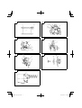 2
2
-
 3
3
-
 4
4
-
 5
5
-
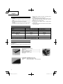 6
6
-
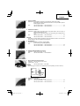 7
7
-
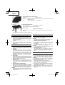 8
8
-
 9
9
-
 10
10
-
 11
11
-
 12
12
-
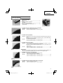 13
13
-
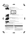 14
14
-
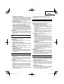 15
15
-
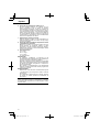 16
16
-
 17
17
-
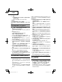 18
18
-
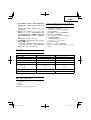 19
19
-
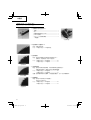 20
20
-
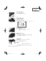 21
21
-
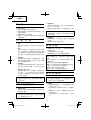 22
22
-
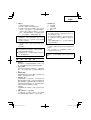 23
23
-
 24
24
-
 25
25
-
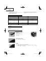 26
26
-
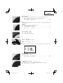 27
27
-
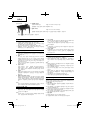 28
28
-
 29
29
-
 30
30
-
 31
31
-
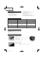 32
32
-
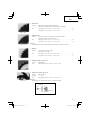 33
33
-
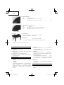 34
34
-
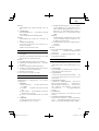 35
35
-
 36
36
-
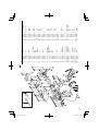 37
37
-
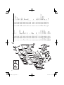 38
38
-
 39
39
-
 40
40


Hitachi C 6 Handling Instructions Manual
- Categoría
- Herramientas eléctricas
- Tipo
- Handling Instructions Manual
- Este manual también es adecuado para
en otros idiomas
- English: Hitachi C 6
Artículos relacionados
-
Hitachi C 6SSl C 7SS Handling Instructions Manual
-
Hitachi Koki C18DL Manual de usuario
-
-
Hikoki CD7SA Manual de usuario
-
-
-
Hikoki C7SB2 Manual de usuario
-
-
-

