Poulan 220LE El manual del propietario
- Categoría
- Motosierras inalámbricas
- Tipo
- El manual del propietario
Este manual también es adecuado para

PoulanPRO
Instruction Manual
Manual de Instrucciones
Manuel d'lnstructions
220 LE / 260 LE
For Occasional Use Only
&
WARNING:
Read and follow all Safety Rules and Operating Instructionsbefore
using this product. Failure to do so can result in serious injury.
ADVERTENCIA:
Lea el manual de instrucciones y siga todas las advertencias e en-
strucciones de seguridad. El no hacerlo puede resultar en lesiones
graves.
AVERTI SSEM ENT:
Lire le manuel d'instructions et bien respecter tousles avertisse-
ments et routes les instructions de s_curit_. Tout d_faut de le faire
pourrait entralner des blessures graves.
Electrotux Home Products, Inc, Electrotux Canada Corporation
104Warren Road 6150 McLaughlin Road
Augusta, GA30907 Mississauga, Ontario L5R4C2
[] The Ele_,olux Group, Ti'_ wortd's No.1 choice,
Kr_H_,,_ CLFANtr_e_NDOUTDO0_Ap,_U4_C_,SCOM_INJ'D
Copynght l<2003 Electrolux Home Products, Inc 530164365 12/16/03

----_ ARNING! This chain _--_
saw can bedangerous! Care-
less orimproperuse cancause
seriousor even fatal injury.
Read and understand the
instruction manual before
using the chain saw.
Always wear appropriate ear protection, eye protection and head protection.
'"_' _ Always use two hands when operatthg the chain saw.
WARNING! Contacting the guide bar tip with any object
should be avoided; tip contact may cause the guide bar to
move suddenly upward andbackward, which may cause se-
rious injury.
Measured maximum kickback value without chain brake for the bar
and chain combination on the label
,1_ WARNING: Always disconnect
spark plug wire and place wire where it can-
not contact spark plug to prevent accidental
starting when setting up, transporting, ad-
justing or making repairs except carburetor
adjustments.
Because a chain saw is a high-speed wood-
cutting toot, special safety precautions must
be observed to reduce the risk of accidents.
Careless or improper use of this tool can
cause serious injury.
PLAN AHEAD
• Read this manual carefully untii you com-
pletely understand and can follow all safety
rules, precautions, and operating instruc-
tions before attempting to use the unit.
• Restrict the use of your saw to adult users
who understand and can follow safety
rules, precautions, and operating instruc-
tions found in this manual.
• Wear protective gear. Always use steel-
toed safety footwear with non-slip soles;
snug-fitting clothing; heavy-duty, non-slip
gloves; eye protection such as non-fog-
ging, vented goggles or face screen; an
approved safety hard hat; and sound barrb
ers (ear plugs or mufflers) to protect your
hearing. Regular usersshould havehear-
ing checked regularly as chain saw noise
can damage hearing. Secure hair above
shoulder length.
Hearing Safety Hat
Protection _Eye
"_d_l qMpiJ_ Protection
Snug
Fittin Heavy Duty
Clothing Gloves
Safety Safety Chaps
Shoes
Keep all parts of your body away from the
chain when the engine is running.
Keep children, bystanders, and animals a
minimum of 30 feet (10 meters) away from
the work area. Do not allow other peopte
or animals to be near the chain saw when
starting or operating the chain saw.
Do not handle or operate a chain saw
when you are fatigued, ill, or upset, or if you
have taken alcohol, drugs, or medication.
You must be in good physical condition
and mentally alert. Chain saw work is
strenuous. If you have any condition that
might be aggravated by strenuous work,
check with your doctor before operating a
chain saw.

• Carefullyplanyoursawingoperationinad-
vance.Donotstartcuttinguntilyouhavea
clearworkarea,securefooting,and,ifyou
arefellingtrees,aplannedretreatpath.
OPERATE YOUR SAW SAFELY
• Do not operate a chain saw with one hand.
Serious injury to the operator, helpers, by-
standers or any combination of these per-
sons may result from one-handed opera-
tion. A chain saw is intended for
two-handed use.
• Operate the chain saw only in a wetbventi-
lated outdoor area.
• Do not operate saw from a ladder or in a
tree.
• MakesurethechainwiH not makecontact
with any object while starting the engine.
Never try to start the saw when the guide
bar is in a cut.
• Do not put pressure on the saw at the end
of the cut. Applying pressure can cause
you to lose control when the cut is com-
pleted.
• Stop the engine before setting the saw
down.
• Do not operate a chain saw that is dam-
aged, improperly adjusted, or not com-
pletely and securely assembled. Always
replace bar, chain, hand guard, or chain
brake immediately if it becomes damaged,
broken or is otherwise removed.
• With the engine stopped, hand carry the
chain saw with the muffler away from your
body, and the guide bar and chain to the
rear, preferably covered with a scabbard.
MAINTAIN YOUR SAW IN GOOD
WORKING ORDER
• Have all chain saw service performed by a
qualified service dealer with the exception
of the items listed in the maintenance sec-
tion oftMs manual. Forexample, if improp-
er tools are used to remove or hold the fly-
wheel when servicing the clutch, structura]
damage to the flywheel can occur and
cause the flywheel to burst.
• Make certain the saw chain stops moving
when the throttle trigger is released. For
correction, refer to CARBURETOR AD_
JUSTMENTS.
• Never modify your saw in any way.
• Keep the handles dry, clean, and free of oil
or fuel mixture.
• Keep fuel and oil caps, screws, and fas_
tenets securely tightened.
• Use only Poulan PRO_; accessories and
replacement parts as recommended.
HANDLE FUEL WITH CAUTION
• Do not smoke while handling fuel or while
operating the saw.
• Eliminate all sources of sparks or flame in
the areas where fuel is mixed or poured.
There should be nosmoking, open flames,
orworkthat could cause sparks. Allow en-
gine to cool before refueling.
• Mix and pour fuel in an outdoor area on
bare ground; store fuel in a cool, dry, well
ventilated place; and use an approved,
marked container for all fuel purposes.
Wipe up all fuel spills before starting saw.
• Move at least 1g feet (3 meters) from fuel-
ing site before starting engine.
• Turn the engine off and let saw coo] in a
non-combustible area, not on dry reaves,
straw, paper, etc. Slowly remove fuel cap
and refuel unit.
• Storethe unit and fuetin an area wherefuel
vapors cannot reach sparks or open
flames from water heaters, electric motors
or switches, furnaces, etc.
KICKBACK
,_WARNING: Avoid kickback which
car/result in serious injury. Kickback is the
backward, upward or sudden forward motion
of the guide bar occurring when the saw
chain near the upper tip of theguide bar con-
tacts any object such as a log or branch, or
when the wood closes in and pinches the
saw chain in the cut. Contactfl/g a foreign ob-
ject in the wood can also result in loss of
chain saw control.
• Rotational Kickback can occur when the
moving chain contacts an object at the up-
per tip of the guide bar. This contact can
cause the chain to dig into the object,
which stops the chain for an instant. The
result is a lightning fast, reverse reaction
which kicks the guide bar up and back to-
ward the operator.
• Pinch-Kickbackcan occur when the the
wood closes in and pinches the moving
saw chain in the cut along the top of the
guide bar and the saw chain is suddenly
stopped. This sudden stopping of the
chain results in a reversal of the chain
force used to cut wood and causes the
saw to move in the opposite direction of the
chain rotation. The saw is driven straight
back toward the operator.
• Pull-In can occur when the moving chain
contacts a foreign object in the wood in the
cut alcng the bottom of the guide bar and the
saw chatn is suddenly stopped. This sudden
stopping pulls the saw forward and away
from the operator and could easily cause the
operator to lose contrc4 of the saw.
Avoid Pinch-Kickback:
• Be extremely aware of situations or ob-
structions that ca n ca use material to pinch
the top of or otherwise stop the chain.
• Do not cut more than one log at a time.
• Do not twist the saw as the bar is with-
drawn from an undercut when bucking.
Avoid Pull-In:
• Always begin cutting with the engine at full
speed and the saw housing against wood.
• Use wedges made of plastic or wood.
Never use metal to hold the cut open.
Kickback Path

AvoidObstructions
CiearTheWorkingArea
REDUCE THE CHANCE OF
KICKBACK
• Recognize that kickback can happen.
With a basic understanding of kickback,
you can reduce the element of surpbse
which contributes to accidents.
• Never let the moving chain contact any ob-
ject at the tip of the guide bar.
• Keep the working area free from obstruc-
tions such as other trees, branches, rocks,
fences, stumps, etc. Eliminate or avoid
any obstruction that your saw chain could
hit while you are cutting. When cutting a
branch, do not let the guide bar contact
branch or other objects around it.
• Keep your saw chain sharp and properly
tensioned. A loose or dull chain can in-
crease the chance of kickback occurring.
Follow manufacturer's chain sharpening
and maintenanceinstructions. Checkten-
sion at regular intervals with the engine
stopped, never with the engine running.
Make sure the chain brake nuts are se-
curely tightened after tensioning the chain.
• Begin and continue cutting at full speed, if
the chain is moving at a slower speed,
there is greater chance of kickback occur-
ring.
• Cut one log at a time.
• Use extreme caution when re-entering a
previous cut.
• Do not attempt cuts starting with the tip of
the bar (plunge cuts).
• Watch for shifting logs or other forces that
could close a cut and pinch or fall into
chain.
• Use the Reduced-Kickback Guide Bar
and Low-Kickback Chain specified for
your saw.
MAINTAIN CONTROL
Stand to the left
of the saw _
Thumb on
underside of
handlebar
Never reverse
hand positions
Elbow locked
Thumb on underside of
handlebar
• Keep a good, firm grip on the saw with both
hands when the engine is running and
don't let go. A firm grip will help you reduce
kickback and maintain control of the saw.
Keep the fingers of your left hand encir-
cling and your left thumb under the front
handlebar. Keep your right hand com-
pletely around the rear handle whether
your are right handed or left handed. Keep
your left arm straight with the elbow
locked.
• Position your left hand on the front handle-
bar so it is in a straight line with your right
hand on the rear handle when making
bucking cuts. Never reverse right and left
hand positions for any type of cutting.
• Stand with your weight evenly balanced on
both feet.
• Stand slightly to the ]eft side of the saw to
keep your body from being in a direct line
with the cutting chain.
• Do not overreach. You could be drawn or
thrown off balance and lose control of the
saw.
• Donotcutaboveshoulderheight. Itisdiffi-
cult to maintain control of saw above
shoulder height.
KICKBACK SAFETY FEATURES
_ WARNING: The followingfeatures
are included on your saw to help reduce the
hazard of kickback; however, such features
will not totally eliminate this danger As a
chain saw user, do not re{y only on safety de-
vices. You must follow all safety precau-
fions, instructions, and maintenance in this
manua{ to help avoid kickback and other
forces which can result in serious injury.
• Reduced-Kickback Guide Bar, designed
with a smalJ radius tip which reduces the
size of the kickback danger zone on the
bar tip. A Reduced-Kickback Guide Bar
has been demonstrated to significantly re-
duce the number and seriousness of kick-
backs when tested in accordance with
safety requirements for gasoline powered
chain saws as set by ANSI B175.1.
ReducedKickbackSym(_etrica_GuideBar
_t_all RadiusTip

SymmetricalGuideBar _._'_4_
large Radius Tip
• Low-Kickback Chain, designed with a
contoured deNh gauge and guard link
which deflect kickback force and allow
wood to grad ually ride into the cutter. Low-
Kickback Chain has met kickback per-
formance requirements when tested on a
representative sample of chain saws be-
low 3.8 cubic inch displacement specified
in ANSI B175.f.
Contoured DepthGauge
_[k ElongatedGuardLink
Deflects
iekbackforce
Low-Kickback '_ anda_lowswood
Chain to gradually ride
Infocutter
_Oan Obstruct Material
Nota Low-Kickback Chain
• Front Hand Guard, designed to reduce the
chance of your left hand contacting the chain
if your hand slips off the front handlebar.
• Position of front and rear handlebars, de-
signed with distance between handles and
"in-line" with each other The spread and
"in-line" position of the hands provided by
this design work together to give balance
and resistance in controlling the pivot of
the saw back toward the operator if kick-
back occurs.
CHAIN BRAKE AND CKA ANGLE
• Chain Brake, designed to stop the chain in
the event of kickback.
_I_WARNING: WE DO NOT REP-
RESENT AND YOU SHOULD NOT AS-
SUME THAT THE CHAIN BRAKE WILL
PROTECT YOU IN THE EVENT OF A
KICKBACK. Kickback is a lightning fast ac-
tion which throws the bar and rotating chain
back and up toward the operatoE Kickback
can be ca used by allowing contact of the bar
tip in the danger zone with any hard object.
Kickback can also be caused by pinching the
saw chain along the top ofthe guide bar. This
action may push the guide bar rapidly back
toward the operator. Either of these events
may cause you to lose controt of the saw
which could result in serious injury or even
death. DO NOT RELY UPON ANY OF THE
DEVICES BUILT INTO YOUR SAW. YOU
SHOULD USE THE SAW PROPERLY AND
CAREFULLY TO AVOID KICKBACK. Re-
duced-kickback guide bars and low-kick-
back saw chains reduce the chance and
magnitude of kickback and are recom-
mended. Your saw has a low kickback chain
and bar as original equipment. Repairs on a
chain brake should be made by an autho-
rized servicing dealer. Take your unit to the
place of purchase if purchased from a ser-
vicing dealer, or to the nearest authorized
master service dealer.
• Tip contact in some cases may cause a light-
ning fast reverse REACTION, kicking the
guide bar up and back toward the operator.
• Pinching the saw chain along the top of the
guide bar may push the guide bar rapidly
back toward the operator.
• Either of these reactions may cause you to
lose controt of the saw which could result
in serious injury.Do not rely exclusively
upon the safety devices built into your saw.
,1_ WARNING: Computed kickback
angle (CKA) listed on your saw and listed in
the CKA table below represents angie of
kickback your bar and chain combinations
will have when tested in accordance with
CSA and ANSI standards. When purchasing
replacement bar and chain, considerations
should be given to the lower CKA values.
Lower CKA values represent safer angles to
the user, higher values indicate more angle
and higher kick energies. Computed angles
represented in the non-activated cotumn in-
dicate total energy and angle associated
without activation of the chain brake during
kickback. Activated angle represents chain
stopping time relative to activation angle of
chain brake and resulting kick angle of saw.
In all cases lower CKA values represent a
safer operating environment for the user.
The following guide bar and chain combina-
tions meet kickback requirements of CSA
Z62.1, Z62.3, & ANSI B175.1 when used on
saws listed in this manual. Use of bar and
chain combinations other than those listed is
not recommended and may not meet the
CKA requirements per standard.
Computed kickback an_le (CKA) Table
BAR
MODEL P/N Length CHAIN P/N
220 LE 530044834 16" 952051480
260 LE 530044835 18" 952051481
CKA without chain brake
8°
6°

NOTE: If this saw is to be used for commer-
cial Icggthg, a chain brake is required and shall
not be removed or otherwise disabled to com-
ply with Federal OSHA Regulations for Com-
mercial Legging,
SAFETY NOTICE: Exposure to vibrations
through prolonged use of gasoline powered
hand tools could cause b]oed vesse] or nerve
damage in the fingers, hands, and joints of
people prone to circulation disorders or
abnormal swellings, Prolonged use in cold
weather has been linked to blood vessel
damage in otherwise healthy beop]e, If
symptoms occur such as numbness, pain,
loss of strength, change in skin color or texture,
or loss of feelieg in the fingers, bend& or joints,
discontinue the use of this tool and seek
medical attention. An anti-vibration system
does not guarantee the avc_dance of these
problems. Users who operate power tools on
a continual and regular basis must monitor
closely their physical condition and the
condition of this tool
SPECIAL NOTICE: Your saw is equipped
with a temperaturelimiting muffler and spark
arresting screen which meets the
requirements of California Codes 4442 and
4443. All U.S. forest land and the states of
California, Idaho, Maine, Minnesota, New
Jersey, Oregon, and Washington require by
law that many internal combustion engines
to be equipped with a spark arresting screen.
Ifyou operate a chain saw in a state or locale
where such regulations exist, you are legally
responsible for maintaining the operating
condition of these parts. Failure to do so is
a violation of the law. Refer to the SERVICE
section for maintenance of the spark
arresting screen.
Failureto follow all Safety Rules and Precau-
tions can result in serious injury. If situations
occur which are not covered in this manual,
use care and good judgement. If you need
assistance, contact your authorized service
dealer or call 1-800-554-6723.
STANDARDS: This saw is ]isted by Under-
writer's Laboratories, Inc., and the Canadian
Standards Association in accordance with:
ANSI BI75.1=280g American National
Standard for Powered Tools ~ Gasoline
Powered Chain Saw ~ Safety Requirements
CSA Z62.1-03 Chain Saws ~ Occupational
Health and Safety
CSA Z62.3-96 Chain Saw Kickback Occu-
pational Health and Safety
Protective gloves (not provided) should be
worn during assembly.
ATTACHING THE BAR & CHAIN (If not
already attached)
_]kWARNING: If received assembled,
repeat all steps to ensure your saw is properly
assembled and all fasteners are secure. Al-
ways wear gloves when handling the chain.
The chain is sharp and can cut you even when
it is not moving!
1. Loosen and remove the chain brake nuts
and the chain brake from the saw.
2. Remove the plastic shipping spacer (if
present).
Location of shipping spacer
a_ Chain Brak_e
Ch Nuts
Bar Tool
3. Turn adjusting screw on bar counter-
clockwise to move the tensioning rack as
far as it will go toward the front of the bar.
(__ Adjusl_g
Tensioning Rac_k _
4. Slide the bar behind clutch drum until bar
stops against clutob drum sprocket.
5. Prepare the chain by checking the proper
direction. Without following the illustration it
is easy to I_ace the chain on the saw in the
wrong direction. Use the illustration of the
chain to determine the proper direction.
Tip of
Bar
DIIRECTION OF ROTATION
Cutters Dept_ Gauge
Drive Links

6. Placethechainoverandbehindthe
clutch,fittingthedrivelinksinthedutch
drumsprocket.
Placechainontothesprocket
7. Fitbottomofdrivelinksbetweenthe
teethinthesprocketinthenoseofthe
guidebar.
8. Fitchaindrivelinksintobargroove.
9. Pullthebarforwarduntilthechainis
snuginthegrooveofthebar.Ensureall
drivelinksareinthebargroove.
10.Holdguidebaragainstthesawframe
andinstallthechainbrake.
1I.Replacethechainbrakenutsandfighten
fingertight.Oncethechainistensioned
youwillneedtotightenchainbrakenuts.
CHAINTENSION(Includingunitswith
chainalready installed)
NOTE: When adjusting chain tension,
make sure the chain brake nuts are finger
tight only. Attempting to tension the chain
when the chain brake nuts are tight can
cause damage.
Checking the tension:
Use the screwd river end of the chain adjust-
ment tool (bar tool) to move the chain around
the bar. If the chain does not rotate, it is too
tight. Iftoo loose, the chain will sag belowthe
bar.
Chain Brake Nuts Tool (Bar Tool)
Adjusting the tension:
Chain tension is very important. Chain
stretches during use. This is especially true
during the first few times you use your saw.
Always check chain tension each time you
use and refuel your saw.
An adjusting screw (located on the guide bar)
is used to adjust the tension of the chain (see
illustration).
1. Turn adjusting screw clockwise until
chain solidly contacts bottom of guide
bar rail.
Guide bar
Ad2Ur 2i' g
2. Using the screwdriver end of the bar tool,
roll chain around guide bar to ensure all
links are in bar groove.
3. Lift up tip of guide bar to check for sag.
Release tip of guide bar, then turn adjus#
ing screw until sag does not exist.
4. Tighten bar clamp nuts securely with the
bar tool.
Chain Brake t
Nuts
5. Use the screwdriver end of the bar tool to
move chain around guide bar.
6. If chain does not rotate, it is too tight.
Slightly loosen bar clamp nuts and loos-
en chain by turning the adjusting screw.
Retighten bar clamp nuts.
7. If chain is too loose, it will sag below the
guide bar. DO NOT operate the saw if the
chain is loose.
,I_WARNING: If the saw is operated
with a loose chain, the chain could jump off
the guide bar and result in serious injury.

KNOW YOURSAW
READ THIS INSTRUCTION MANUAL AND SAFETY RULES BEFORE OPERATING YOUR
CHAIN SAW. Compare the illustrations with your unit to familiarize yourself with the location of
the various controls and adjustments. Save this manual for future reference.
Chain
Adjustment Tool Front Hand Guard
(Bar Tool)
Chain Muffler
Bar Oil Fill Cap
Housing
Front Handle
Starter Rope
ON/STOP
Switch
Primer
Bulb
Fuel Mix Fill Cap
Cylinder Cover
Throttle
Lockout
Rear
Handle
Chain
Direction
of Travel
Throttle Choke/ Chain Chain Chain
Trigger Fast Idle Brake Catcher
Lever
ON/STOP SWITCH
The ON/STOP SWITCH is used to stop the
engine.
THROTTLE TRIGGER
The THROTTLE TRIGGER controls engine
speed.
THROTTLE LOCKOUT
The THROTTLE LOCKOUT must be pressed
before you can squeeze the throttle trigger.
This feature prevents you from accidentally
squeezing the trigger.
CHOKE/FAST IDLE LEVER
The choke and fast idle are set by pulling the
CHOKE/FAST iDLE LEVER out to the full ex-
tent for cold starting or after refueling. The
choke provides additional fuel to the engine
during cold starting.
PRIMER BULB
The PRIMER BULB circulates fuet to the
carburetor to provide quicker starting.
Brake Nuts Guide Bar
CHAIN BRAKE
The CHAIN BRAKE is a device designed to
stop the chain if kickback occurs. The chain
brake activates automatically in the event of
kickback. The chain brake activates manu-
ally if the front hand guard is pushed forward.
The chain brake is disengaged by pulling the
front hand guard back toward the front han-
dle as far as possible.
CHAIN TENSION
it is normal for a new chain to stretch during first
30 minutes of operation. You should check
your chain tensicn frequently. See CHAIN
TENSION under the ASSEMBLY section.
_I_WARNING: Muffler is very hotdur-
ing and after use. Do not touch the muftler or
allow combustible material such as dry
grass or fuel to do so.

_lk WARNING: Remove fuel cap slow-
ly when refueling.
FUELING ENGINE
This engine is certified to operate on
unleaded gasoline. Before operation,
gasoline must be mixed with a good quality
synthetic 2-cycle air-cooled engine oil
designed to be mixed at a ratio of 40:1.
Poulan/Weed Eater brand synthetic oil is
recommended. A 40:1 ratio is obtained by
mixing 3.2 ounces (95 m0 ofoil with 1 gallon (4
liters) of unleaded gasoline. Included with this
saw is a 3.2 ounce container of Poulan/Weed
Eater brand synthetic oil. Pour the entire
contents of this container into 1 gallon of
gasoline to achieve the proper fuel mixture.
DO NOT USE automotive or boatoil. These
oils will cause engine damage. When mixing
fuel fotlow the instructions printed on the
container. Always read and follow the safety
rules listed under HANDLE FUEL WiTH
CAUTION.
BAR AND CHAIN LUBRICATION
The bar and chain require continuous lubri-
cation. Lubrication is provided by the auto-
matic oiler system when the oil tank is kept
filled. Lack of oil will quickly ruin the bar and
chain. Too little oil will cause overheating
shown by smoke coming from the chain and/
or discoloration of the bar.
In freezing weather oil will thicken, making it
necessary to thin bar and chain oil with a
small amount (5 to 10%) of #1 Diesel Fuel or
kerosene. Bar and chain oil must be free
flowing for the oil system to pump enough oil
for adequate lubrication.
Genuine Poulan or Poulan PROQ) bar and
chain oil is recommended to protect your unit
against excessive wear from heat and
friction. Poulan or Poulan PRO® oH resists
high temperature thinning. If Poulan or
Poulan PRO® bar and chain oil is not
available, use a good grade SAE 30 oil.
• Never use waste oil for bar and chain lubri-
cation.
• Always stop the engine before removing
the oil cap.
IMPORTANT
Experience indicates that alcohol-blended
fuels (called gasohol or using ethanol or
methanol) can attract moisture which leads
to separation and formation of acids during
storage. Acidic gas can damage the fuel
system of an engine while in storage. To
avoid engine problems, the fuel system
should be emptied before storage for 30
days or longer. Drain thegns tank, start the
engine and let it run until the fuel lines and
carburetor are empty. Use fresh fuel next
season. See STORAGE section for addi-
tional information.
,mbWARNING: The chain must not
move when the engine runs at idle speed. If
the chain moves at idle speed refer to CAR-
BURETOR ADJUSTMENT within this
manual Avoid contact with the muffler. A hot
muffler can cause serious burns.
To stop the engine move the ON/STOP
switch to the STOP position.
To start the engine hold the saw firmly on the
ground as illustrated. Make sure the chain is
free to turn without contacting any object.
Use only 15 - 18 inches (38 - 45 cm) of
rope per pull.
Hold saw firmty while pulling starter rope.
Starter rope handle
..../_-_/_41__.,[_._ Left hand
I, onf ont
Right foot through rear handle
IMPORTANT POINTS TO REMEMBER
When pulling the starter rope, do not use the full
extent of the rope as this can cause the rope to
break. Do not let starter rope snap back. Hold
the handle and let the rope rewind slowly.
For cold weather starting, start the unit at
FULL CHOKE; allow the engine to warm up
before squeezing the throttle trigger.
NOTE: Do not cut material with the choke/
fast idle lever at the FULL CHOKE position.
STARTING A COLD ENGINE (or
warm engine after running out of
fuel):
NOTE: In the following steps, when the
choke/fast idle lever is pulled out to the full
extent, the correct throttle setting for starting
is set automatically.
ON/STOP SWITCH
(SIDE VIEW)
.,_ ON
STOP
1. Move ON/STOP switch to the ON posi-
tion.
2. Pull out choke/fast idle to the full extent
(to the FULL CHOKE position).
3. Slowly press primer buth 6 times.
4. Pull the starter rope sharply 5 times with
your right hand. Then, proceed to the
next step.
NOTE: If the engine sounds as if it is trying
to start before the 5th pull, stop pulling and
immediately proceed to the next step.
5. Push the choke/fast idle lever in to the
HALF CHOKE position.

CHOKE/FAST IDLE LEVER
o_,IEW)
I I
Ch k
fast idle lever OFF HALF FULL
6. Pull the starter rope sharply with your
right hand until the engine starts.
7. Allow the engine to run for approximatety
5 seconds. Then, squeeze and release
throttletdgger to allow engineto returnto
idle speed.
STARTING A WARM ENGINE:
1. Move ON/STOP switch to the ON posi-
tion.
2. Pull the choke/fast idle lever out to the
HALF CHOKE position.
3. Slowly press the primer bulb 6 times.
4. Pull the starter rope sharply with your
right hand until the engine starts.
5. Squeeze and release throttle trigger to
allow engine to return to idle speed.
DIFFICULT STARTING (or starting a
flooded engine):
The engine may be hooded with too much
fuel if it has not started after 10 pulls.
Flooded engines can be cleared of excess
fuel by pushing the choke/fast idle lever in
completely (to the OFF CHOKE position)
and then following the warm engine starting
procedure listed above. Ensure the ON/
STOP switch is in the ON position.
Starting could require pulling the starter rope
handle many times depending on how badly
the unit is flooded. If engine fails to start, refer
to the TROUBLESHOOTING TABLE or call
1-500-554-6723.
CHAIN BRAKE
,_kWARNING: If the brake band is
worn too thin it may break when the chain
brake is triggered. With a broken brake band,
the chain brake will not stop the chain. The
chain brake should be replaced by an autho-
rized service dealer if any part is worn to less
than 0.020" (0.5 ram) thick. Repairs on a
chain brake should be made by an autho-
rized service dealer. Take your unit to the
place of purchase if purchased from a ser-
vicing dea]eh or to the nearest authorized
rnaster service dealer.
• This saw is equipped with a chain brake.
The brake is designed to stop the chain if
kickback occurs.
• The inertia-activated chain brake is
activated if the front hand guard is pushed
forward, either manually (by hand) or
automatically (by sudden movement).
• If the brake is already activated, it is
disengaged by pulling the front hand guard
back toward the front handle as far as
possible.
• When cuttthg with the saw, the chain brake
must be disengaged.
Disengaged
_ Engaged
Braking function control
CAUTION: The chain brake must be
checked several times daily. The engine
must be running when performing this proce-
dure. This is the only instance when the saw
should be placed on the ground with the en-
gine running.
Place the saw on firm ground. Grip the rear
handle with your right hand and the front han-
dle with your left hand. Apply full throttle by
fully depressing the throttle trigger. Activate
the chain brake by turning your ]eft wrist
against the hand guard without releasing
your grip around the front band]e. The chain
should stop immediately.
Inertia activating function control
_I_WARNING: When performing the
following procedure, the engine must be
turned off.
Grip the rear hand]ewith your right hand and
the front handle with your left hand. Hold the
chain saw approximately 14 inches (35 cm)
above a stump or other wooden surface. Re-
lease your grip on the front handle and use
the weight of the saw to let the top of the
gwuidebar fall forward and contact the stump.
hen the tip of the bar hits the stump, the
brake should activate.
IMPORTANT POINTS
• Check chain tension before first use and
after I minute of operation. See CHAIN
TENSION in the ASSEMBLY section.
• Cut wood only. Do not cut metat, plastics,
masonry, non-wood building materials, etc.
• Stop the saw if the chain strikes a foreign
object, thspect the saw and repair or re-
place parts as necessary.
• Keepthechain out of dirt and sand. Even a
small amount of dirt will quickly bah a chain
and thus increase the possibility of kickback.
• Practice cutting a few small logs using the
following techniques to get the "feeF of us-
ing your saw before you begin a major
sawing operation.
• Squeeze the throttle trigger and allow
the engine to reach full speed before
cutting.
• Begin cutting with the saw frame
against the log.
• Keep the engine at full speed the entire
time you are cutting.
• AIIowthechaintocutforyou. ExertonJy
light downward pressure, tf you force
the cut, damage to the bar, chain, or en-
gine can result.
10

• Release the throttle trigger as soon as
the cut is completed, allowing the en-
gine to idle. If you run the saw at full
throttle without a cuttthg load, unneces-
sary wear can occur to the chain, bar,
and engine. It is recommended that
the engine not be operated for lon-
ger than 30 seconds at full throttle,
• To avoid losing controlwhen cut is com-
plete, do not put pressure on saw at end
of cut.
• Stop the engine before setting the saw
down after cutting.
TREE FELLING TECHNIQUES
_I_WARNING: Check for broken or
dead branches which can fall while cutting
causing serious injury. Do not cut near bui_d-
thgs or electrical wires Jfyou do not know the
direction oftreefall, norcut at night since you
will not be ale to see well, nor during bad
weather such as rain, snow, or strong winds,
etc. If the tree makes contact with any utility
line, the utility company should be notified
immediately.
• Carefully plan your sawing operation in ad-
vance.
• Cleartheworkarea. You needacleararea
all around the tree so you can have secure
footing.
• Study the natural conditions that can cause
the tree to fall in a pedicular direction.
Natural conditions that can cause a tree to
fall in a particular direction include:
• The wind direction and speed.
• The lean of the tree. The lean of a tree
might not be apparent due to uneven or
sloping terrain. Use a ptumb or level to de-
termine the direction of tree _ean.
• Weight and branches on one side.
• Surrounding trees and obstacles.
Look for decay and rot. tfthe trunk is rolled, it
can snap and fatl toward the operator. Check
for broken or dead branches which can fail on
you while cL_ting.
Make sure there is enough room for the tree to
fall. Maintath a distance of 2-1/2 tree lengths
from the nearest person or other objects. En-
gine nc4se can drown out a warnthg call.
Remove dirt, stones, loose bark, nails, staples,
and wire from the tree where cuts are to be
made.
Plan a clear retreat path to the rear and diag-
onal to the line of fall.
Plan a clear retreat path
:t" ÷- "O" u,,,,,,_ - Direction of Fall
FELLING LARGE TREES
(6 inches (15 cm) in diameter or targer)
The notch method is used to fell large trees.
A notch is cut on the side of the tree in thede-
sired direction of fall. After a felling cut is
made on the opposite side of tree, the tree
will tend to fall into the notch.
NOTE: If the tree has large buttress roots,
remove them before making the notch. If us-
ing saw to remove buttress roots, keep saw
chain from contacting ground to prevent dull-
ing of the chain.
NOTCH CUT AND FELLING THE
TREE
• Make notch cut by cutting the top of the
notch first. Cut through 1/3 of the diameter
ofthetree. Next complete the notch bycut-
ting the bottom of the notch. See illustra-
tion. Once the notch is cut remove the
notch of wood from the tree.
Final felling cut here, 2 inches
5 cm above center o notch.
Firstcot\ '!.,_
Notch _
Second cut_
• After removing the cutout of wood, make
the felling cut on the opposite side of the
notch. This is done by making a cut about
twoinches (5 cm) higher than the center of
the notch. This will leave enough uncut
wood between the felli ng cut and the notch
to form a hinge. This hinge will help pre-
vent the tree from falling in the wrong direc-
tion.
Hinge holds tree on stump and helps
control fall
Opening
of felling
Closing of
notch
NOTE: Before felling cut is complete, use
wedges to open the cut when necessary to
controtthedirection of fall. To avoid kickback
and chain damage, use wood or plastic
wedges, but never steel or iron wedges.
• Be alert to signs that the tree is ready to falh
cracking sounds, widening of the felling cut,
or movement in the upper branches.
• As tree starts to fall, stop saw, put Jtdown,
and get away quickly on your planned re-
treat path.
11

• DONOTcutdownapartiallyfallentree
withyoursaw.Beextremelycautiouswith
partiallyfallentreesthatmaybepoorly
supported.Whenatreedoesn'tfallcom-
pletely,setthesawasideandpulldownthe
treewithacablewinch,blockandtackle,
ortractor.
CUTTING A FALLEN TREE
(BUCKING)
Bucking is the term used for cutting a fallen
tree to the desired log size.
_WARNING: Donotstandonthelog
being cut. Any portion can roll causing loss
of footing and control. Do not stand downhill
of the log being cut.
IMPORTANT POINTS
• Cut only one log at a time.
• Cut shattered wood very carefully; sharp
pieces ofwood could be flung toward oper-
ator.
• Use a sawhorse to cut small logs. Never
allow another person to hotd the log wMe
cutting and never hold the log with you r leg
or foot.
• Do not cut in an area where logs, limbs,
and roots are tangled such as in a blown
down area. Drag the logs into a clear area
before cutting by pulling out exposed and
cleared logs first.
TYPES OF CUTTING USED FOR
BUCKING
,I_WARNING: tf saw becomes
pinched or hung in a log, don't try to force it
out. You ca n lose control of the saw resulting
in injury and/or damage to the saw. Stopthe
saw, drive a wedge of plastic or wood into the
cut until the saw can be removed easily. Re-
start the saw and carefully reenter thecut. To
avoid kickback and chain damage, do not
use a metal wedge. Do not attempt to restart
your saw when it is pinched or hung in a log.
Use a wed e to remove pinched saw
Turn saw OFF and use a plastic or
wooden wedge to force cut open.
Overcutting begins on thetop side of thelog
with the bottom of the saw against the log.
When overcutting use light downward pres_
sure.
Overcutting Undercutting
,1_ WARNING: Never turn saw upside
down to undercut. The saw cannot be con-
trolled in this position.
Always make your first cut on the compres-
sion side oftheiog. Thecompression side of
the log is where the pressure of the log's
weight is concentrated.
First cut on compression side of log
Second out
Second cut
g
First cut on compression side of log
BUCKING WITHOUT A
SUPPORT
• Overcut through 1/3 of the diarneter of the
log.
• Roll the log over and finish with a second
overcut.
• Watch for logs with a compression side to
prevent the saw from pinching. See il-
lustrations for cutting logs with a compres-
sion side.
BUCKING USING A LOG OR
SUPPORT STAND
• Remember your first cut is always onthe
compression side of the tog.
(Refer to the illustrations below for your
first and second cut)
• Your first cut should extend 1/3 of the
diameter of the log.
• Finish with your second cut.
Using a log for support
1st Cut
Undercutting involves cutting on the under-
side of the log with top of saw against the log.
When undercutting use light upward pres-
sure. Hold saw firmly and maintain controt.
The saw will tend to push back toward you.

Using a support stand
2 nd Cut ,_
LIMBING AND PRUNING
,_I_WARNING: Be alert for and guard
against kickback. Do not allow the moving
chain to contact any other branches or ob-
jects at the nose of the guide bar when limb-
ing or pruning. Allowing such contact can re-
sult in serious injury.
d_il_WARNING: Neverclimbintoatree
to limb or prune. Do not stand on ladders,
platforms, a log, or in any position which can
cause you to lose your balance or control of
the saw.
IMPORTANT POINTS
• Work slowly, keeping both hands firmly
gripped on the saw. Maintain secure foot-
ing and balance.
• Watch out for springpo]es. Spdngpoles
are small size limbs which can catch the
saw chain and whip toward you or pull you
off balance. Use extreme caution when
cutting small size limbs.
• Be alert for springback. Watch out for
branches that are bent or under pressure.
Avoid being struck by the branch or the
saw when the tension in the wood fibers is
released.
• Keep a clear work area. Frequently clear
branches out of the way to avoid tripping
over them.
LIMBING
• Always limb atree after it is cut down. Only
then can limbing be done safely and prop-
erly.
• Leave the larger limbs underneath the
felled tree to support the tree as you work.
• Start at the base of the felled tree and work
toward the top, cutting branches and
limbs. Remove small limbs with one cut.
• Keep the tree between you and the chain.
Cut from the side of the tree opposite the
branch you are cutting.
• Remove larger, supporting branches with
the cutting techniques descdbed in BUCK_
ING WITHOUT A SUPPORT.
• Always use an overcuf to cut small and
freely hanging limbs. Undercutting could
cause Jimbs to fail and pinch the saw.
PRUNING
WARNING: Limit pruning to limbs
shoulder height or below. Do not cut if
branches are higher than your shoulder. Get
a professional to do the job.
• Make your fist cut 1/3 of the way
through the bottom of the timb.
• Next make a 2nd cut all the way
through the limb, Then cut a third
overcuUeaving a f to2 inch (2.5 ~ 5cm)
collar from the truck of the tree.
i {l'i Secondcut_'l_ _J_
Third eel j_///
Collar
_]1_ _ Firstcut
Pruning technique
WARNING: Disconnect the spark
plug before performing maintenance except
for carburetor adjustments.
We recommend atl service and adjustments
not listed in this manual be performed by an
authorized service dealer.
MAINTENANCE SCHEDULE
Check:
Fuel mixture {evel .... Before each use
Bar lubrication ....... Before each use
Chain tension ....... Before each use
Chain sharpness .... Before each use
For damaged parfs .. Before each use
For loose caps ...... Before each use
For loose fasteners... Before each use
For loose parts ...... Before each use
Inspect and Clean:
Bar ................ Before each use
Complete saw ....... After each use
Air filter ............. Every 5 hours*
Chain brake ........ Every 5 hours*
Spark arresting screen
and muffler ......... Every 25 hours*
Replace spark plug . Yearly
Replace fuel filter... Yearly
* Hours of Operation
13

AIR FILTER
CAUTION: Donot clean filter in gasoline
or other flammable solvent to avoid creating
a fire hazard or producing harmful evapora-
tive emissions.
Cleaning the air filter:
A dirty air filter decreases engine perform-
ance and increases fuel consumption and
harmful emissions. Always clean after every
5 hours of operation.
1. Loosen 3 screws on cylinder cover.
2. Remove cylinder cover.
3. Remove air filter.
4. Clean the air filter using hot soapywater.
Rinse with clean cool water. Air dry com-
pletely before reinstalling.
5. Lightly oil air filter before fflstallJng to im-
prove the efficiency of aff filter. Use
2-cycle engine oil or motor oil (SAE 30).
Squeeze excess oil from filter.
6. Reinstall air filter.
7. Reinstall cylinder cover and 3 screws.
Tighten securely.
Cylinder
Air Filter Cover
_Screws
Cylinder
Cover
/I
INSPECT MUFFLER AND SPARK
ARRESTING SCREEN
,_IkWARNING: The muffler on this
product contains chemicals known to the
State of California to cause cancer.
As the unit is used, carbon deposits build up
on the muffter and spark arresfing screen,
and must be removed to avoid creating a fire
hazard or affecting engine performance.
Replace the spark arresting screen if breaks
occur.
CLEANING THE SPARK ARREST-
ING SCREEN
Cleaning is required every 25 hours of op_
eration or annually, whichever comes first.
_i utlet
Guide
)
Muffler
Gasfiot
Bolt Cover "_
Looknut
1. Loosen and remove the Iooknut from the
bolt cover.
2. Remove the bott cover.
3. Loosen and remove the 2 muffler bolts.
Remove the muffler, muffler gasket, out-
let guide and backplate. Notice the ori-
entation of these parts for reassembling.
4. Locate the 2 outlet cover screws on the
muffler. Loosen and remove both
screws.
5. Remove the ouflet cover.
_, Outlet Cover BACK VIEW OF
6.
7.
8.
9.
Remove spark arresting screen.
Clean the spark arresting screen with a
wire brush. Replace screen if any wires are
broken or screen is blocked after c{eaning.
Reinstall spark arresting screen.
Reinstall outlet cover and 2 screws. En-
su re outlet cover and both screws are re-
installed correctly (see illustrations) to
prevent damage to the saw. The ex-
haust outlet must face the chain brake
(bar side) of the saw.
Outlet Cover
Exhaust _ _/
outlet
Exhaust Outlet must face chain
brake (bar side) of chain saw
10. Inspect the muffler gasket and replace if
damaged.
11. Reinstall baokplate, ouflet guide, muffler
gasket, and muffler using muffler bolts.
Tighten until secure.
12. Reinstall bolt cover andtocknut. Tighten
securely.
CARBURETOR ADJUSTMENT
_k WARNING: The chain will be mov-
ing during most of this procedure. Wear your
protective equipment and observe all safety
precautions. The chain must not move at idle
speed.
The carburetor has been carefully set at the
factory. Adjustments may be necessary if
you notice any of the following conditions:
• Chain moves at idle. See tDLE SPEED-T
adjusting procedure.
• Saw will not idle. See IDLE SPEED~T ad-
justing procedure.
Idle Speed-T
Allow engine to idle. If the chain moves, idle
istoofast. Ifthe engine stalls, idle is too slow.
Adjust speed until engine runs without chain
movement (idle too fast) or stalling (idle too
slow). The idle speed screw is located in the
area above the primer bulb and is labeled T.
• Turn idle speed screw (T) clockwise to in-
crease engine speed.
14

• Turn idle speed screw (T) counterclock-
wise to decrease engine speed.
If you require further assistance or are unsure
about performing this procedure, contact your
authorized service dealer or call
1-800-554-6723.
BAR MAINTENANCE
If your saw cuts to one side, has to be forced
through the cut, or been run with an improper
amoun_ of bar lubrication it may be necessary
to service your bar. A worn bar will damage
your chain and make cutting difficult.
After each use, ensure ON/STOP switch is in
the STOP position, then clean all sawdust from
the guide bar and sprocket hole.
To maintain guide bar:
• Move ON/STOP switch to the STOP posi-
tion.
• Loosen and remove chain brake nuts and
chain brake. Remove bar and chain from
saw.
• Clean the oil holes and bar groove after each
5 hours of operation.
Remove Sawdust From
Guide Bar _o_
_1_ OilHoles
o _A
• Burring of guide bar rails is a normal process
of rail wear. Remove these burrs with a flat
tile.
• When rail top is uneven, use a fiat tile to re-
store square edges and sides.
-_ FileRail Edges_ _Jr_
and Sides
Square
Worn Groove Correct Groove
Replace guide bar when the groove is worn,
the guide bar is bent or cracked, or when exce-
ss heating or burring of the rails occurs. If re-
placement is necessary, use only the guide bar
specified for your saw in the repair parts list or
on the decal located on the chain saw.
CHAIN SHARPENING
Chain sharpening is a complicated task that
requires special tools. We recommended
you refer chain sharpening to a professional
chain sharpener
IGNITION TIMING
Ignition timing is fixed and nonadjustable.
SPARK PLUG
The spark plug should be replaced each
year to ensure the engine starts easier and
runs better.
1. Loosen 3 screws on cylinder cover.
2. Remove the cylinder cover.
3. Pull off the spark plug boot.
4. Remove spark plug from cylinder and dis-
card.
5. Replace with Champion RCJ-7Y agark
plug and tighten securely with a 3/4 inch
(19 ram) socket wrench. Spark plug gap
should be 0.025 inch (0.6 ram).
6. Reinstall the spark plug hoot.
7. Reinstall the cylinder cover and 3 screws.
]qghten securely.
er
STORAGE
WARNING: Stop engine and allow
to cool, and secure the unit before storing or
transporting in a vehicle. Store unit and fuel
in an area where fuel vapors cannot reach
sparks or open flames from water heaters,
electric motors or switches, furnaces, etc.
Store unit with ati guards in place. Position so
that any sharp object cannot accidentally
cause injury to passersby. Storethe unit out
of reach of children.
• Before storing, drain all fuel from the unit.
Start engine and allow to run until it stops.
• Clean the unit before storing. Pay particu-
lar attention to the air intake area, keeping
it free of debris. Use a mild detergent and
sponge to clean the plastic surfaces.
• Do not store the unit or fuel in a closed area
where fuel vapors can reach sparks or an
open flamefrom hot water heaters, electric
motors or switches, furnaces, etc.
• Store in a dry area out of the reach of chil-
dren.
CAUTION: It is important to prevent gum
deposits from forming in essentiat fuel system
parts such as the carburetor, fuel tilter, fuel
hose, or fuel tank during storage. Alcohol
blended fuels (called gasohol or using ethanol
or methanol) can attract moisture which leads
to fuel mixture separaticn and formation of
acids during storage. Acidic gas can damage
the e{/gine.
NEED ASSISTANCE?
Call 1-800-554-6723.
NEED SERVICE PART?
Contact your authorized service dealer.
15

TROUBLESHOOTING TABLE
_k WARNI Always stop unit and disconnect spark plug before perforrning all of
NG:
the recommended remedies below except remedies that require operation ofthe unit.
TROUBLE CAUSE REMEDY
Engine wil( not 1. Ignition switch off. 1. Move ignition switch to ON.
start or will run 2. Engine flooded. 2. See "Difficult Starting" in
only a few Operation Section.
seconds after 3. Fuel tank empty. 3. Fill tank with correct fuel mixture.
starting. 4. Spark plug not firing. 4. Install new spark plug.
5. Fuel not reaching 5. Check for dirty fuel filter; replace.
carbureton Check for kinked or split fuel line;
repair or replace.
Engine will 1. Carburetor requires I. See "Carburetor Adjustment" in the
not idle adjustment. Service and Adjustments Section.
properly. 2. Crankshaft seals worn. 2. Contact an authorized service dealer.
Engine will not 1. Air filter dffty. 1. Clean or replace aff filter.
accelerate, 2. Spark plug fouled. 2. Clean or replace plug and regap.
lacks power, 3. Chain brake engaged. 3. Disengage chain brake.
or dies under 4. Carburetor requires 4. Contact an authorized service dealer.
a load. adjustment.
Engine 1. Too much oi( mixed with 1. Empty fuel tank and refill with
smokes gasoline, correct fuel mixture.
excessively.
Chain moves I. Idle speed requires 1. See "Carburetor Adjustmenfl' in the
at idle speed, adjustment. Service and Adjustments Section.
2. Clutch requires repaff. 2. Contact an authorized service dealer.
ELECTROLUX HOME PRODUCTS, INC,,
warrants to the original purchaser that each
new Poulan PRO® brand gasoline chain
saw is free from defects in material and
workmanship and agrees to repaff or replace
under this warranty any defective gasoline
chain saw as follows from the odgin al date of
purchase.
2 YEARS - Parts and Labor, when used for
Household purposes.
60 DAYS - Parts and Labor, when used for
Commercial, Professional, or Income Pro-
ducing purposes.
30 DAYS - Parts and Labor, if used for rental
purposes.
This warranty is not transferable and does
not cover damage or liability caused by im-
proper handling, improper maintenance, or
the use of accessories and/or attachments
not specifically recommended by ELEC-
TROLUX HOME PRODUCTS, INC., for this
chain saw. Additionally, this warranty does
not cover damage caused by improper han-
dling, improper maintenance, or ff the saw is
altered in any waywhich in ourjudgementaf-
fects its condition or operation. This warranty
does not cover tune-up, spark plugs, filters,
starter ropes, starter spdngs, chain sharpen-
ing, bars, chains, and other parts which wear
and require replacement with reasonable
use during the warranty period. This warran-
ty does not cover predelivery set-up, lnstal-
lafion of guide bar and chain, and normal ad-
justments explained in the instruction
manual such as carburetor adjustments and
chain tension adjustments. This warranty
does not cover transportation costs.
THIS WARRANTY GIVES YOU SPECIFtC
LEGAL RIGHTS, AND YOU MAY HAVE
OTHER RIGHTS WHICH VARY FROM
STATE TO STATE.
NO CLAIMS FOR CONSEQUENTIAL OR
OTHER DAMAGES WILL BE ALLOWED,
AND THERE ARE NO OTHER EXPRESS
WARRANTIES EXCEPT THOSE EXPRESS-
LY STIPULATED HEREIN.
SOME STATES DO NOT ALLOW LIMITA-
TIONS ON HOW LONG AN IMPLIED WAR-
RANTY LASTS OR THE EXCLUSION OR
LIMITATIONS OF INCIDENTAL OR CONSE-
QUENTIAL DAMAGES, SO THE ABOVE
LIMITATIONS OR EXCLUSION MAY NOT
APPLY TO YOU.
The policy of ELECTROLUX HOME PRO-
DUCTS, INC., is to continuously improve its
products. Therefore, ELECTROLUX HOME
PRODUCTS, INC., reserves the right to
change, modify, or discontinue models, de-
signs, specifications, and accessories of all
prod ucts at any fime without notice or obJiga-
fion to any purchaser.
16

YOUR WARRANTY RIGHTS AN D OBLIGA-
TIONS: The U.S. Environmental Protection
Agency, California Air Resources Board, Envi-
ronment Canada and ELECTROLUX HOME
PRODUCTS, INC., are pleased to explain the
emissions control system warranty on your
year 2002-2004 small off-road engine. InCali-
fornia, all small off-toed engines must be de-
signed, built, and equipped to meet the State's
stdogent anti-smog standards. ELECTRO-
LUX HOME PRODUCTS, INC., must warrant
the emission controt system on your small off-
road engine for the periods of time listed below
provided there has been no abuse, neglect, or
improper maintenance of your small off-road
engine. Your emission control system includes
ports such as the carburetor and the ignition
system. Where a warrantable condition exists,
ELECTROLUX HOME PRODUCTS, INC.,
will repair your smati off-road engine engine at
no cost to you. Expenses covered under war-
ranty include diagnosis, ports and labor.
MANUFACTURER'S WARRANTY COVER-
AGE: Ifany ecnissions related par[ on your en-
gine (as listed under Emissions Control War-
ranty Pads List) is defective or a defect in the
materials or workmanship of the engine
causes the failure of such an emission related
por[, the pad will be repaired or replaced by
ELECTROLUX HOME PRODUCTS, INC.
OWNER'S WARRANTY RESPONSIBILI-
TIES: As the small off-road engine engine
owner, you are responsible for the perfor-
mance of the required maintenance listed in
your instruction manual. ELECTROLUX
HOME PRODUCTS, INC., recommends that
you retain all receipts covering maintenance on
your small off-road eogine, but ELECTROLUX
HOME PRODUCTS, iNC., cannot deny war-
ranty solely for the lack of receipts or for your
failure to ensure the performance of all sched-
uled maintenance. As the small off-road en-
gine engine owner, you should be aware that
ELECTROLUX HOME PRODUCTS, INC.,
may deny you warracty coverage if your small
off-road engine engine or a part of it has failed
due to abuse, neglect, improper maintenance,
unapproved modifications, or the use of parts
not made or approved by the original equip-
ment manufacturer. You are responsible for
presenting your small off-road engine to an
ELECTROLUX HOME PRODUCTS, INC.,
authorized repair center as soon as a problem
exists. Warranty repairs should be completed
in a reasonable amount of time, not to exceed
30 days. If you have any questions regarding
your warranty rights and responsibitities, you
should contact your nearest authorized service
center or call ELECTROLUX HOME PROD-
UCTS, INC., at 1-800-554-6723. WARRAN-
TY COMMENCEMENT DATE: The warranty
period begins on the date the small off-road
engine is purchased. LENGTH OF COVER-
AGE: This warranty shati be for a period of two
years from the initial date of purchase. WHAT
IS COVERED: REPAIR OR REPLACE-
MENT OF PARTS, Repair or replacement of
any warranted part will be performed at no
charge to the owner at an approved ELEC-
TROLUX HOME PRODUCTS, INC., servic-
ing center. Ifyou have any questions regarding
your warranty rights and responsil:41itJes, you
sbeu]d contact your nearest authorized service
center or ca]i ELECTROLUX HOME PROD-
UCTS, INC., at 1-800-554-6723. WARRAN-
TY PERIOD: Any warracted part which is not
scheduled for replacement as required mainte-
nance, or which is scheduled only for regular
inspection to the effect of "repair or replace as
necessary" shall bewarranted for 2 years. Any
warranted part which is scheduled for replace-
ment as required maintenance shaft be war-
ranted for the period of time up to the first
scheduled replacement point for that part.
DIAGNOSIS: The owner shall not be charged
for diagnostic labor which leeds to the deter-
mination that a warracted part is defective ifthe
diagnostic work is performed at an approved
ELECTROLUX HOME PRODUCTS, INC.,
servicing cecter. CONSEQUENTIAL DAM-
AGES: ELECTROLUX HOME PRODUCTS,
INC., may be liable for damages to other en-
gine components caused by the failure of a
warranted part still under warranty. WHAT IS
NOT COVERED: All failures caused by abuse,
neglect, or improper maictenance are not cov-
ered. ADD-ON OR MODIFIED PARTS: The
use of add-on or modified ports can be
grounds for disallowing a warranty claim.
ELECTROLUX HOME PRODUCTS, INC., is
not liable to cover failures of warranted parts
caused by the use of add-on or modified pods.
HOW TO FILE A CLAIM: If you have any
questions regarding your warranty rights and
responsibilities, you sbeuld contact your near-
est authorized service center or call ELEC-
TROLUX HOME PRODUCTS, INC., at
1-800-554-6723. WHERE TO GET WAR-
RANTY SERVICE: Warrar_ty services or re-
pairs shall be provided at aft BLECTROLUX
HOME PRODUCTS, INC., service centers.
Call: 1-800-554-6723 MAINTENANCE, RE-
PLACEMENT AND REPAIR OF EMISSION
RELATED PARTS: Any ELECTROLUX
HOME PRODUCTS, INC., approved replace-
ment par[ used inthe performance of any war-
ranty maintenance or repair on emission re-
lated parts will be provided without charge to
the owner if the par[ is under warranty. EMIS-
SION CONTROL WARRANTY PARTS LIST:
Carburetor, Ignition System: Spark Plug (cov-
ered up to maintenance schedule), Ignition
Module, Muffler including catalyst. MAINTE-
NANCE STATEMENT: The owner is responsi-
ble for the performance of all required mainte-
nance as defined in the instruction manual.
17

The information on the product label indicates which standard your engine is certified.
Example: (Year) EPA Phase 1 or Phase 2 and/or CALIFORNIA.
41 I 61 I el I
This engine is certified to be emissions compliant for the foiJow]ng use:
[]Moderate (50 hours)
[] Intermediate (125 hours)
[] Extended (300 hours)
18

ADVERTENCIA: iEsta
sierra de cadena puede ser
peligrosa! El uso descuidado
oindebido deesta herramlenta
puede causar graves heddas.
r_ Lea y comprenda el
manual de instruc-
clones antes de usar la
sierra.
Use siempre la proteccl6n de oidos apropiada, la proteccion de
ojos y la protecciSn de la cabeza.
Use siempre Jasdos manos cuandotrabaje con la sierra de
caderla.
ADVERTENClA: Debe evitarse cualquier contacto de
la punta de labarra guia con cualguier objeto, ya quepuede
causar que la barra guia se desplace repentlnamente hacia
ardba y hacia atras, con posibles graves heridas.
M_ximo valor de kickback medido sin el freno de cadena para la
combinaci6n de barra y cadena indicada en la etiqueta.
_lk ADVERTENCIA: Desconecte
siempre el cable de la bujia y coloquelo
donde no puede entrar en contacto con el
bujia, para evitar cualquier arranque acci-
dental al preparar, transportar, ajustar o re-
parar el aparato, excepto en el caso de
ajustes al carburado£
Debido a que las sierras de cadena son
instrumentos para cortar madera a alta veto-
cidad, deben observarse precauciones de
seguridad especiales para reducir el riesgo
de accJdentes. El uso descuidado oindebJ-
do de esta herramienta puede causar
graves heridas.
PIENSE ANTES DE PROOEDER
• Antes de _lizar la sierra, lea attentamente
este manual basra estar seguro o compren-
dedo completamente y poder seguir todas
las reglas de seguridad, precauci6ns e
instrucciones de uso que se dan en el.
• Umite ei uso de la sierra a aquellos usuarios
adultos que comprendad y puedan imple-
mentar todas las precauclones, reglas de
seguridad e instrucciones de uso que se en-
cuentran en este manual.
Protecci6n Casco Duro
de
Oidos
Protecci6n de
"_.1 _ Ojos
Ropa Ajustada
Guantes de
Uso Industria
Zapatos de Pantorrilleras
Seguridad
Use equipo protector. Siempre use calzado
de seguridad con puntas de acero y suelas
anti-deslizantes; ropa ajustada el cuerpo;
guantes gruesos de uso industrial anti-desii-
zantes; proteccJ6n de ojos tales como galas
de seguridad que no se empa6an y ccn ab_
erturas de ventiliacJ6n o mascara protectora
para la cara; casco duro aprobado; y barrera
de sonido (tapones de oido u orejeras anti-
sonJdo) para proteger la audici6n. Los que
usan sierras de fuerza deberan hacerse re-
vJsar la audici6n frecuentemente ya que el
ruido de las sierras de cadena puede da6ar
los oidos.
19

• Mantenga todas tas lirtes del cuerli aleja-
das de la cadena siempre que el motor est6
en funcionamierto.
• Mantenga a los nJSos, eslictadores y anJ-
males a una distancia minima de 10 metros
(30 pies) del area de trabajo o cuando esla
haoienco arrancar el motor.
• No levante ni opere la sierras de cadena
cuando esta faigado, enfermo, ansioso o si
ha tornado alcohol, drogas o remedios. Es
imprescindible que ed. este en buenas con-
diciones fisicas y alerta mentalmerte. Si ud.
sufre de cualquier condici6n que pueda em-
peorar con el trabajo arduo, ases6rese con
su me:tico.
• No ponga en marcha la sierra sin tenet un
area de trabajo despejada, superticie est-
able para pararse y, si esla derrubando
arboles, un camino predeterminado de retro-
ceso.
USE LA SIERRA OBSERVANDO
TODOS LOS PROCEDIMIENTOS
DE SEGURIDAD
• Mantenga las dos manos en las rnanijas
siempre que el aparato este en march& El
uso de1 aparato con una sola mano puede
causar graves hetidas al usuatio, a los asis-
tentes, o a los espectadores. Las sierras de
cadena estan dise_adas para que se las use
col/las dos l;qanos en todo momento.
• Haga uso de la sierra de cadena Qnicamente
en lugares exteriores bien ventillados.
• No haga uso de la sierra desde las escaler_
as portaflles ni de los _rboles.
• Aseg_rese de que la cadena no vaya a hac-
er contacto con ningQn objeto antes de lin-
eren maroha el motor. Nunca intente hacer
arrancar la sierra con la barra quia en un
corte.
• No aplique presi6n a la sierra at final de los
cortes. Aplicar presi6n liede hacer que
pierda et control al completarse el corte.
• Pare el motor antes de aliyar la sierra en
ning_n lado.
• No linga en funcionamiento la sierra de ca-
dena si est_ da_ada, incorrectamente ajus-
tad& o si no est_ armada completa y segu-
ramente. Siempre cambie el protector de
mano immediatamente si 6sta queda daiia-
do, roto, o se sale pot cualquier motivo.
• Cuando cargue la sierra de cadena en las
manos, h_galo con el motor parado, el silen-
ciador alejado del cuerl!, y la cade{/a hacia
arras y cubierta con un estuche.
MANTENGA LA SIERRA EN BUE-
NAS CONDICIONES DE FUNC-
TIONAMIENTO
• L]eve la sierra de cadena a un distribuidor
autorizado del servicio para que haga todo
servicio menos aquellos procedimJentos lis-
tados en la secci6n de mantenimiento de
este manual. Por ejempplo, si se usan her-
ramJentas que no correslinden para retirar
o sostener el volante al hacer servicio al em-
brague, bueden ocurrir da_os estructura]es
al volante y causar que reviente.
• Aseg_rese de que la cadena se detenga lir
completo cuando se suetta el gatillo. Para
hacer correcciones, vea los AJUSTES AL
CARBURADOR.
• Nunca haga modificaciones de ninguna in-
dole a su sierra.
• Martenga las manijas secas, limpias y libres
de aceite o de mezcia de combustible.
• Martenga las tapas y los fijadores blen fijos.
• Use exclusivarnente los acoesodos y re-
puestos Poulan PRO_; recomendados.
MANEJE EL COMBUSTIBLE CON
EXTREMO CUIDADO
• No fume mientras trabaaal con el combustible
ni cuando esta haciendo uso de ta sierra.
• Elimine todas las lisibles fuentes de chis-
lis o llamas en las areas donde se mezcla o
vierte el combustible. No debe haber el fu-
mar, llamas abiedas, o trabajo que lidria
causar chislis. Permita que el motor es fifo
antes de reaprovisionar de combustible.
• Mezcle y vierta et combustible afuera y use
recipiente aprobado para combustibles y
marcado como tal. Umpie todos los der-
rames de combustible.
• Alejese a por Io mendos 3 metros (10 pies)
del lugar de abastecimie{/to antes de liner
el motor en marcha.
• Aligue el motor y deje que la sierra se
enfde en un lugar libre de substancias com-
bustibles y no sobre hcjas secas, lija, l!-
pel, etc. Retire la tali lentamente y reabas-
tezca el alirato.
• Guarde el aparato e{/ un espaciuo fresco,
seco y bien ventilado donde los vapores del
combustible no lieden entrar en contacto
con chispas ni llamas ablertas provenientes
de termotangues, motores o interruptores
el_ctricos, calefactores centrales, etc.
RECULADA
_k ADVERTENCIA: Evite reculada le
pueden causar graves heridas. Reculada
es el movimiento hacia el frente, hacia atr_s
o r_pidamente hacia adelante, esto puede
ocu rrir cua ndo ta punta de la barra guia de la
sierra de cadena entra en contacto con cual-
quier objeto como puede ser otra rama o
tronco, o cuaRdo la madera se cierra y atas-
ca mieRtras se hace el corte. El entrar en
contacto con algQn objeto extra5o a la mad-
era le puede causar al usuado la p6rdida del
controt de ta sierra de cadena.
• La Reculada Rotacional liede acontecer
cuando la cadena en movimiento entra en
contacto con algQn objeto en la lirte superi-
or de la punta de la barra guia puede causar
que la cadena entre al material y se detenga
lit un instante. Et resultado es una reacci6n
inversa, a velocidad de rel_mpago, que hace
recular la barra guia hacia artiba y hacia
atr_s hacia el usuari&
• La Reculada pot Atasco acontecen cuan-
do la madera se cierra y atasca la cadena en
movimiento en el corte a Io largo de la parte
superior de la barra guia y la cadena se de-
tiene repenflnamente. Esta detenci6n re-
lintina de la cadena tie{/e como resultado
una inversi6n de la fuerza de la cadena usa-
da para codar madera y causa que la sierra
se mueva en se{/tido opuesto al de la rota-
2O

ci6n de la cadena. La sierra directamente
hacia arras en direcci6n al usuano.
• La Reculada por Impulsibn puede acon-
tecer cuando la cadena en movimiento entra
en contacto con algQn objeto extraSo a la
madera en el code a Iolargo de la perte infe-
rior de la barra guia y la cadena se detiene
repertinamente. Esta detenci6n repertina
de la cadena tira de la sierra adelante y lejos
del usuario y pedria hacer facilmente al
usuario perder el control de la sierra.
Para Evitar la Reculada por Atasco:
• Mant6ngase completamente conciente de
toda situaci6n u obstrucci6n que pueda hac_
er que el material presione la cadena en la
parte superior o que pueda parar la cadena
de cualquier otro modo.
• No code m_s de un tronco a la vez.
• No retuerza la sierra al retirar la barra de un
code ascendiente cuando esta seccionando
troncos.
Para Evitar la Reculada por Impulsi6n:
• Empiecetodocorteoon elmotor aceleradoa
fondo y con la caja de la sierra apoyada con-
tra la madera.
• Use cuSas de plastico o de madera (nunca
de metal) para mantener al:4erto el coke.
Trayectoria de
la Reculada
Evite las obstrucciones
Despeje el Area de Trabajo
REDUZCA LAS PROBABILIDADES
DE RECULADA
• Reconozcaque lasierra puede recular.Con
unacomprensi6n basicadel fenomenode la
reculada de la sierra, ud. puede reducir el
elemento de sorpresa que contribuye a los
accider_es.
• Nuncapermita quelacadenaenmovimiento
toque ningenobjeto en la punta de la barra
guEa.
• Mantengael areadetrabajolibredeob_truc-
ciones como per ejemplootros arboles,ra-
mas, piedras,cercas, tocones, etc. Elimine
o evite todo ob_tAculoque la sierra peeda
enfrentar al cortar. AI codar una rama, no
deje labarra guiaentrar encontacto conotra
rama o otros objetos alrededor.
• Mantenga la sierra afilada y con la tensi6n
correcta. Las cadenascon 130oofilo oflojas
incremer_an la probabilidad de reculada.
Siga lasinstruccionesdelfabricanteparaaft-
lar y efectuar mar_enimientode la cadena.
Venfique la tensi6n a ir_ervalos regulares
con el motor parsdo, rlUrlCa en march&
AsegQrese de que las tuercas de la freno de
cadena est6n ajustadas firmemente.
• Empiece y efectQe la totalidad de carla corte
con el acelerador a fondo. Si la cadena se
esta moviendo a una velocidad menor que la
m_xJma, hay mas probabilidad de que la
sierra recule.
• Corte Qnicamente un tronco a la vez.
• Use cuidado extremo al entrar de nuevo en
un corte ya empezado.
• No intente hacer codes empexando con la
punta de la barra (cortes de taladro).
• Tenga cuidado con troncos que se despla-
zany con las demos fuerzas que pedrian
cerrar un code y apretar la cadena o oaer
sobre ella.
• Use la Barra Guia Reducidora de Recula-
das y la Cadena Minimizadora de Recula-
das.
MANTENGA EL CONTROL
P_trese hacia la
izquierda de la
sierra
ar por
debajo de la
Nunca invierta manija
la posici6n de
las manos
Codo rigido
El pulgar por debajo de
la manija
• Sostener firmemente con las dos manos le
ayudara a mantener el control de la sierra.
No aftoje. Mantenga la mano derecha envol-
viendo totalmente la manija trsera, sea ud.
derecho o zurdo. Sostenga la manija delan-
tera con la mano izquierda, cotocando el pul-
gar debajo de la manija y rodeando la manija
con los dedos. Martenga el brazo izquierdo
totalmente extendido con el codo fijo.
• Coloque le mano izquierda el la manija de-
lantera, de modo que quede en tinea recta
con la mano derecha en la manija trasera,
cuando est6 haciendo cortes de secciona-
miento. Parese levemente hacia laizquierda
de la sierra para evitar que el cuerpe este el
linea directa con la cadena.
• Parese con el peso dJstribuido Jgualmente
entre los dos pies.
• Parese levemente hacia la izquierda de la
sierra de cadena para evitar que el cuerpo
est6 en linea directa con la cadena.
21

• No se extienda excesivamente. La sierra
puede impulsario o empujarlo y ud. puede
perder el equilibrio y el control de la sierra.
• No corte arriba del nival de los hombros. Es
difldl mantener el control de la sierra sJest_
por encJma del nJvel de los hombros.
DISPOSITIVOS DE SEGURIDAD
CONTRA LAS REGULADAS
_kADVERTENCIA: Los siguJentes
dispositivos han sido incluJdos en la sierra
para ayudar a reducir el riesgo de reculadas;
sin embargo, tales Jmptementos no pueden
elJmJnar totalmente esta peligro. Como
usuario de sierra de cadena, ud. no debe
confiarse solamente en los dispositJvos de
seguridad. Ud. debe seguir todas las pre-
cauciones de segurided, instrucciones y
rnantenirniento que se encuentran en este
manual para ayudar a evitar {as reculadas y
otras fuerzas que pueden oausar graves
heridas.
• Barra Guia Reducidora de Reculadas, dis-
edada con punta de redio pequeiio que re_
duce el tamaSo de la zona de pelJgro en la
punfa de la barra. Este tipo de barra ha de-
monstrado que reduce significalJvamente la
cantided y la seriedad de las reculedas
cuando han sido examinado de acuerdo con
ANSI (American National Standards Insti-
tute, Inc.) B175.1.
BarraGu_aSim6tricaReducidoradeReculadas
Zona De Peligro
pur]la de Radio
Pequer3o
Z_na De
Barra Gu[a Simdtrica Pellgro
Punta de Radio Grarlde
• Las Cadet/as Minimizadoras de Reculadas
han salJsfecho los requisJtos de rendimiento
en gruebas col/una muestra representalJva
de sierras de cedena con desplazamiento
de menos de 3,8 pulgadas, como se espe-
cifica en ANSI B175.1.
M cador de Profundidad Perfilado
_r Estabdn Protector
" Alargado
Desv_ala ft_erza
de reacci6n y
pem_ite que la
Cadena Mini- \ madera entre
m zadora de gradua]menfe a
Reculadas _acuchiNa
PuedeObStruirMaterial
NOun CadenaMin_mizadorade Reculadas
• Protector de Mano Delantera, disedado para
reducir la grobabilidad que su mano izquier-
da entre en contacto con la cadena, si la
mano se desgrende de la manija delantera.
• La posici6n de las manijas delantera y tras-
era, diseiiadas con dJstancia entre las man-
Jjasy "en lined' la una con la otra. La separa-
cJ6n y la colocaci6n en linea que este dJseiio
provee se combinan para dar eduilibrio y re-
sJstencJa para controlar la propulsi6n de la
sierra hacia el usuario si acontece una recu-
led&
FRENO DE CADENAY ANGULO
ACR
• Freno de Cadena, disedado para detener la
cadena en el caso de reculada.
,1_ ADVERTENCIA: NUESTRA
COMPAi_IA NO REPRESENTA Y USTED
NO DEBERA ASUMIR QUE EL FRENO DE
CADENA LO PROTEGER/k EN CASO DE
RECULADAS. Una reculada es una acci6n
rapida la cual ]anza la barra y la cadena rota-
tiva hacia atras y hacia arriba en direcci6n al
usuario. Una reoulada podda set causada
cuando se permite que ]a punta de la barra
en la zona de petigro entre en contacto con
cualquier objeto en la zona superior de {a
barra gu[a. Esta acci6n puede empujar la
barra guia rapidamente hacia atras en direc-
ci6n donde se encuentra el usuado. Cua]-
quiera de estos dos acontecimientos puede
causar que el usuario pierda el control de la
sierra ]o que podria resultar en lesiones de
alta gravedad o hasta la muerte. NO DE-
PENDA ClEGAMENTE EN CUALQUIERA
DE LOS DtSPOS]TIVOS INCLUIDOS EN
SU CUIDADOSAMENTE PAPA EV]TAR
LAS RECULADAS. Las barras guia reduci-
doras de reculadas y ]as cadenas de sierra
de baja acci6n de reculadas reducen la oca-
si6n y magnitud de tas recu]adas y son re-
comendadas. Con su sierra vienen in-
clufdas una cadena de baja acci6n de
reculadas y una barra de equipo original.
Las reparaciones de{ freno de cadena deb-
er_n ser efectuadas por un distdbuidor atu-
roizado del servicio. Lleve su aparato ai lu-
gar de compra, si Io adquiri6 en una agencia
de servicio, o al agente perito autorizado
para este tipo de servicio mas cercano.
• E] contacto con ]a pqrta de la sierra puede
causar una REACCION contrada que a una
velocidad vertiginosa expulsa la espeda ha-
cJa arriba y hacia arras, en direccJed al
operador.
• SJla cadena queda atrapada por la parte su-
perior de la espada, 6sta puede rebotar
bruscamente hacia el operador.
• Cualquiera de estas dos reacciones puede
provocar la i_rdida del control de la motosJe-
rra y causar una grave lesJ6n. No coRffe ex-
clusivamente et/ los disposJtivos de seguri-
dad que incorpora su sierra.
_k ADVERTENCIA: El angulo com-
putado de reculada (ACR) que consta el la
sierra (como CKA) y el la tabla a continuci6n,
representa el anlglulo de reculada que tendra
la corn binaci6n de barra y cadena de su apa-
rato, el ser probada de acuerdo con los pa-
drones CSA y ANSI. AI comprar barra y ca-
dena de repuesto, deben tomarse en
22

consideraci6nlosvaloresmasbajosde
ACR.LosvaloresmasbajosdeACRre-
presentan_ngulosm_ssegurosparael
usuario,mientrasqualosvaloresm_saltos
indicanmayoranguloyenergiasmasaltas
enlasreculadas.Losanguloscomputados
representadosenlacolumnano-activada
Jndicanlaenergiatotalyelanguloasociado
sinactivaci6ndelfrenodecadenaduranteia
reculada.Elanguloactivadorepresentael
tiempodedetenciSndelacadenarelatJvoal
anguloconactivaci6nyel_nguloresultante
dereculadadelasierra.
LasJguientecombinaci6ndebarraguiayca-
dena,satisfacelosrequisitosencontrade
reculadasdeCSlZ62.1,Z62.3ydeANSI
B175.f,alsetusadasenconjuntoconlas
sierrasquemencionamosenestemanual.
Elusodecualquierotracombinaci6ndebar-
rayoadenanollqencionadaenelmanualno
esrecomendadoyadem_s,puedequeno
satisfagalosrequisitosdelasnormasde
CKA.
Tabla de bngu o computado de reculada (ACR-[C KA])
BARRA N°Pza.
MODELO N°Pza. Largo Cadena ACR sin ffeno de cadena
220 LE 530044834 16" 952051480 8°
260 LE 530044835 18" 952051481
6 °
AVISO: Siesta sierra ha de usarse para el
tumbado comercial de arboles, un freno de
cadena se requJere y no sera quitado nJsera
lisiado de otra manera conformarse con las
Regulaciones Federales del OSHA para el
tumbado comercial de arboles.
AVISO SEGURIDAD: El estarexpuesto
alas vibraciones traves del uso prolongado
de herramientas de fuerza a gasolina puede
causar daiios a los vasos sanguineoso a los
nervJos de los dedos, las manosy las coyun-
turas en aquellas personas que tienen pro-
pensidad a los trastomos de la clrculaci6n o
a las hinchazonees anormales. El uso pro-
Iongado en tiempo frio ha sldo asociado con
dafios a los vasos sanguirleos de personas
que por otra parte se encuentran en perfecto
estado de salud. Si ocurren sintomas tales
como el entumecimiento, el dolor, la falta de
fuerza, las cambios en el color o la textura de
la piel o falta de sentido en los dedos, las
manos o las coyunturas, pare de suar esta
maquina immediatamente y procure atem
si6n medica. Los slsternas de antl-vibra-
ci6n no garantizan que se eviten tales pro-
blemas. Los usuarios que haoen uso
continuoy protongandode las herramientas
de fuerza deben fiscalizar atentamente su
estado fisJco y el estado det aparato.
AVISO ESPECIAL: Su sierra viene
equJpada con silencJador limitador de
temperatura y con rejilla antichispa que
cumple los requJsJtos de los C6digos de
California 4442 y 4443. Todas las tierras
forestadas federales, mas los estados de
California, Idaho, Maine, Minnesota, Nueva
Jersey, Washington y Oreg6n, requieren pot
ley que muchos motores de combustJ6n
interna esten equipados con rejJlla
antichispa. Si usted usa una sierra de
cadena donde existen tales reglamentos, ,
usted tlene {a responsablhdad jundlca de
mantener estas piezas en oorreoto estado
de funcionameineto. De Io contrario, estara
en infracci6n de la ley. Refiera a la secci6n
de{ SERVlCIO para el mantenimJento de la
rejilla antichispas.
El no cumplJmJento de todos los reglas de
seguridad e de las precauci6nes puede ten-
er graves heridas como resultado. Si acon-
teoen situaoJones no prevJstas en este
manual, tenga cuidado y use buen criterio.
SJ neoesita ayuda, entre en contacto col/su
distribuidor autorizado dei servicio o Ilame al
nQmero 1-800-554-6723.
CRITERIOS: Este producto esta enlista-
do por Underwdter's Laboratores, Inc., de
acuerdo con:
ANSI B175.1-2000 Padr6n Estadouni-
dense Nacional para Herramientas de Fuer-
za -Sierra de Cadena A Gasolina-Requisi-
tos de Seguridad
CSA Z62.1-03 Seguridad y Salud Ocupa-
cional en relaci6n con las Sierras de Cadena
CSA Z62.3-96 Seguridad y Salud Ocupa-
cional en relaci6n con Reculadas de Sierras
de Cadena
Es necessarJo utJlizar guantes protectores
(no incluidos) durante el montaje.
INSTALACION DE LA BARRA Y LA
CADENA (si no vinieron ya instaladoas)
_kADVERTENCIA: Verifique cada
paso del montaje si recibi6 la sierra ya arm a-
da. Use siempre quantes protectiores al to-
car la cadena, iLa cadena es filosa y Io
puede cortar, aQn no estando en movimien-
to!
1. Afloje y saque las tuercas de la freno de
cadena y la freno de cadena de la sierra.
2. Retire el separador de plastico (si pres-
ente).
23

Ubicaci6n del separador de pl&stico
Tuercas del
Freno de freno de cadena
cad
Herramienta
3. Gire el tornillo de ajuste en la barra para
mover el piii6n de tensi6n tan lejos como
se posible en direcci6n hacia la parte de-
lantera de la barra.
Tomillo de
_ Ajuste
Piii6n de Te_isioh_ __ c
4. Haga deslizar la barra por detr_s de1 ci-
lindro de1 embrague hasta que la barra
se detenga ai tocar el engranaje de1 cili n-
dro del embrague.
a
5. Use la ilustraci6n de la cadena para de-
terminar la direcci6n correcta.
Punta de
la Barra
DEBERAN APUNTAR EN
DIRECCtON A LA ROTACtON
Cuchillas Marcador de Profundidad
Eslabones de Funcionamiento
6. Cc_oque ]acadena por encima y detras del
embrague, poner las eslabones de funcio-
namiento end cilindro del embrague.
Apoye ]a cadena en et engranaje
7. Coloque los eslabones de propulsi6n
entre los dientes de la engranaje en la
punta de la barra.
8. Coloque los eslabones de propulsi6n en
la ranura de la barra.
9. Tire la barra hacia adelante hasta que la
cadena quede tirante en ta ranura de la
barra. Asegure todas las eslabones de
propulsi6n estan en el ranura de la barra.
10. Sostenga la barra g uia contra el bastidor
de la sierra e instale la freno de cadena.
11. Repongalas tuercas dela frenode cade-
nay ajQstelas con los dedos. Ajuste las
tuercas de la freno de cadena despues
de que la cadena est6 tensionada.
TENSION DE LA CADENA (inclusive
los aparatos con la cadena ya instalada)
AVISO: AI hacer ajuste a la tensi6n de la
cadena_ asseg_rese que las tuercas del fre-
nodeoadenaest6n ajustadasa manoQnica-
mente. Si intenta tensionar {a cadena con
las tuercas del freno de cadena ajustadas,
puede da_ar el aparato.
Para verificar la tensibn:
Use la purta destornilladora de ]a herramienta
doble para hacer girar la cadena alrededor de
la barra. Si la cadena no gira, esta demasiado
tirante. Siesta demasiado floja, se ]a vera co]-
gar separada de la parte inferior de la barra.
Tuerca del de la Cadena (Herra-
freno de cadena mienta de la Barra)
Para ajustar la tensi6n:
La tensi6n de la cadena es muy importante.
ha cadena se va estirando con el uso, espe-
cialmente durante las primeras veces que
usa la sierra. Verifique sin falta la tensi6n de
la oadena oaga vez que use la sierra y oada
vez que la abastezca de combustible.
Un tornillo de ajuste(situado en la barra de la
guia) se utiliza para ajustar la tensi6n de la
cadena (v6a la ilustraci6n).
1. Gire el tomillo de ajuste a la derecha (en
el sentido del reloj basra entra en con-
tactoconso damentee fondode re de
la barra guia.
24

Barra Guia
2. Usandolaherramientadelabarra, haga
girarlacadenaalrededordelabarraguia
para asegurarse de que todos los esla-
bones se encuentren dentrode las ranu-
ras de la barra.
3. Levante la punta de la barra guia para
asegurarse qua nonguna partede la ca-
dana se encuentre floja o cuelgue.
Suelte la pu nta de la barra, entonces gire
el tornillo de ajuste hasta que la cadena
quede tirante.
4. Ajuste las tuercas de la freno de cadena
con la herramienta de la barra. Apriete
firmemente.
CONOZCA EL APARATO
5. Use ]a punta en forma de destomil]ador
de ]a herramienta de la barra para hacer
rotar ]a cadena por la barra.
6. Si no puede hacer rotar la cadena, esta
demasiado ajustada. Afloje ]evemente
las tuercas de ]a freno de cadena y afloje
cadena dar vuelta el tomi]lo de ajuste ha-
cia la izquierda (en contra del sentido del
re]oj). Vue]va a ajustar las tuercas de la
freno de cadena.
7. Si ]a cadena se encuentra demasiado
floja, colgara por debajo de ]a barra guia.
NO USE la sierra si la cadena se en-
cuentra floja.
_ADVERTENClA: Si la sierra se
funciona con un cadena flojo, la cadena
podria saltar de la barra y resultado en acci-
dentes muy graves.
LEA ESTE MANUAL DEL USUARIO Y LAS REGLAS DE SEGURIDAD ANTES DE USAR LA
SIERRA DE CADENA. Compare las ilustraciones con su aparato para familiarizarse con la ubica-
ci6n de los varios contro]es y ajutes. Guarde este manual para uso futuro.
Herramienta de Protector
de Mano Manija Delantera
Ajuste de la Cadena Delantera Cuerda de Arranque
(Herramienta de la
Barra) Interruptor
:_Cadena Silenciador ON/STOP
Bombeador
Tapa del Tanque de
Lubricante de Barra Caja del Tapa del Tanque
Arranque de Combustible
Tapa del Cilindro
_ ,r_ Bordes de,torte Marcador de profundidad
Acelerador VZ Y / _'J _5_./
Manija / ,_" "_:_ / Eslab&ones_e 4unc,onaJmiento DireccJ6n de
Trasera I' ( Rotaci6n de la
Tornillo de Ajuste Cadena
GatHIo/ _laalranhCaade_ta_bapi_r/ / Ca tadFored°_eaCeadena Barra _r
P buia
Acelerador Freno de Cadena
25

INTERRUPTOR ON/STOP
El INTERRUPTOR ON/STOP esta acostum-
brado a detener la maquina.
GATILLO DE ACELERADOR
El GATILLO DE ACELERADOR controla ve-
Iocidad de m_quina.
TRABA DEL ACELERADOR
Es necesario apretar pdmerola TRABA DEL
ACE LE RADOR para poder accionar el acel-
erador. Este dispositivo previene el aciona-
miento accidental del acelerado£
PALANCA DEL CEBADOR/MARCHA
LENTA RAPIDA
El cebador y la marcha lenta rapida sol/fijadas
tirando la PALANCA DEL CEBADOR/MAR-
CHA LENTA RAPIDA completamente para ar-
rancar el aparato en frio o despues reaprovi-
sionado de combustible. La palanca del
cebador provee combustible adicional al motor
al arrancar frio.
BOMBEADOR
El BOMBEADOR circula combustible al car-
burador.
FRENO DE CADENA
El FRENO DE CADENA esta dise_ado para
detener la cadena en caso de reculada. El fre-
no de cadena se activa autom_ticarnente en
caso de reculadas. El freno de cadena se actJ-
va manualmente si empujan al protector de
mano delantero adelante. Para desactivar el
freno de cadena, tire Io mas posible del protec-
tor de mano delantero habla la manija delan-
tera.
TENSION DE LA CADEI',L&.
ES Normal que las cadenas nuevas se 8stJisn
durante los ptimeros 30 minutos de uso. Deb-
er_l verificarse la tensipn de la cadena frecuen-
temente. Vea TENSION DE LA CADENA en
la secci6n de MONTAJE.
,I_ADVERTENCIA: El silenciador es
extremedament caliente durante el uso y
despues de usar aparato. No toque el silen-
ciador ni permita que el material combustible
tal como gasolina o hierba seca hagan con-
tacto.
,_tkADVERTENCIA: Remueva la
tapa del tanque de combustible lentamente
al reabastecer combustible.
ABASTECIMIENTO DEL MOTOR
Este motor esta habllitado para funcionar con
gasolina sin i_omo. Antes de usar, se debera
mezblar la gasoNna con un aceite de sint6tico
de buena calidad para motores de 2 tiempos
enftiados a aire dise6ado para ser usado en
una mezbla con proporbl6n de 40:1.
Recomendamos el aceite de sint6tico de la
marca Poulan/Weed Eater_. Se obtiene una
proporci6n de 40:1 mezclando 3,2 onzas (95
ml) de aceite con cada gal6n (4 litros) de
gasolina sin plomo. Se inbluyeccn esta sierra
un recipiente de 3,2 onzas (95 ml) de aceite de
sint6tico de la marca Poulan/Weed Eate£
Adiera el cor_enido er_ero de este recipiente
en 4 litros de gasc4ina para alcanzar le mezcla
apropiada del combustible.
NO USE aceite para autom6viles ni para
barcos. Estos aceites da6aran el motor. AI
mezclar combustible, siga las instrucciones
impresas en el recipiente de aceite. Lea
siempre y siga las reglas de seguddad que
se encuentran bajo MANEJE EL
COMBUSTIBLE CON EXTREMO
CUIDADO.
LUBRICACION DE LA BARRA Y DE
LA CADENA
La barra y la cadena requieren lubricabl6n
constante. El sistema autom_tico de lubri-
caci6n proveela lubdcaci6n necesaria mien-
tras se mantenga Ileno el tanque de aceite.
Lafalta deaceite arruinar_la barray tacade-
na rapidamente. El use dedemasiado poco
aciete causara exceso de calentamiento
que ser_detectable pot el humo proveniente
de la cadena y/o por la descoloracion de la
barra.
Cuando la temperaturea es inferior a O
grados centdgrados, el aceite se pone m_s
grueso, tornando necesada la adicion de
una pequeSa cantidad (de 5 a 10%) de Fuel
Oil #1 (#1 Diesel Fuel) o queros¢n para diluir
el aceite de la barra y la cadena. El aceite
para barra y cadena fluir libremente para que
el sistema de lubricaci6n pueda bombear
suficiente aceite para lubdcar
adeouadarnente.
Se recomienda el aceite Poulan o Poulan
PRO(_) genuino para barra y cadena para
proteger el aparato contra el desgaste
excesivo provocado pot el calory la fricci6n.
El aceite Poulan o Poulan PROC_ resiste la
p_rdida de espesura a alias temperaturas.
Si no nay disponibilidad de aceite para barra
y cadena Poulan o Poulan PRO_) use un
aceite de buena calidad tipo SAE 30.
• Nunca utilice aceite usado para la lubtica-
bl6n de la barra y de la cadena.
• Pare siempre el motor antes de abrir la tapa
del tanque de aceite.
IMPORTANTE
La expedenbla india que los combustibles
mezclados con alcohol (los Ilamados gasohot
o los que conflenen etanol o los que contienen
etanot o metanol) pueden atraer humedad, Io
que puede causar la separaci6n y la formaci6n
de acidos durarte el almacenamierto. La ga-
solina acfdica buede da_ar el sistema de com-
bustible del motor durante el almacenamiento.
Para evitar problemas con el motor, deber_ va-
ciarse el sistema de combustible antes de ala-
macenar el aparato por 30 dias o m_s. Vacie
et tanque de combustible, ponga el motor en
marcha y d_jeto en marcha hasta que las
Ifneas de combustible y el carburador queden
vacios. Cuandovaya a usar el aparato nueva-
mente, use combustible fresco. Vea la secci6n
de ALAMACENAJE para mas informablones.
26

IIL________A._
_]IbAUVI"N/I"NL;IA:Lacadenano
debemoversecuandoelmotorseencuentre
enmarchainactiva.Silacadenasemueve
enmarchainactiva,yealasecci6nde
AJUSTESALCARBURADOReneste
manual.Evitecontactoconelsilenciador.
Unsilenciadorcalientepoddacausarque-
madurasmuygraves.
Paradetenerelmotor,muevaelinterruptor
ON/STOPalaposici6nSTOR
Para poner en marcha el motor, sujete la
sierra firmemente en el suelo como se ilus-
tra.AsegQresede quela cadena pueda mov-
erse libremente sin tocar ningQn objeto.
Use Qnicamente de 38 - 45 cm (15 a 18
pulgadas) de cuerda por tir6n.
Sujete la sierra firmemente mientras
tira de la cuerda de arranque.
Mango de la cuerda de arranque
' La mano iz-
l/ quierda en
, ' la mango
El pie derecho en el intebor de la
mango trasera.
PUNTOS IMPORTANTES PARA
RECORDAR
AI tirar de la cuerda de arranque, no use la
extensi6n completa de la cuerda ya que esto
puede causar que la cuerda se parta. No
permita que la cuerda de arranque regrese a
su lugar bruscamente. Sujete el mango y
permita que la cuerda rebobine lentamente.
Para arranques bajo condiciones de clima
frio, ponga en marcha el motor con el ceba-
dot en la posici6n FULL CHOKE; permita
que el motor caliente antes de apretar el ga-
tillo acelerador.
AVISO: No intente a cortar ningQn tipo de
material si la palanca del cebador/marcha
lenta rapida se encuentran en la posicion
FULL CHOKE.
PARA ARRANCAR EL MOTOR
FRIO (o motor caliente despu_s de
quedar sin combustible)
AVISO: En los pasos siguientes, cuando ta
palanca del cebador/marcha lenta rapida se
activa en su maxima extensi6n, automatica-
mente fijara la aceleraci6n para la puesta en
march&
INTERRUPTOR ON/STOP
(VISTA LATERAL)
STOP
1. Mueva el interruptor ON/STOP a la posi-
ci6n ON.
2. Tire de la palanca del cebador/marcha
lenta rapida su maxima extensi6n.
3. Lentamente, opnma ei bombeador 6
veces.
4. Firmemente, tire det mango de ta cuerda
de arranque 5 veces con su mano dere_
cha. Luego, pase al siguiente paso.
AVISO: Si e] motor parece que est6 intentan-
do arrancar antes del quinto tir6n, pare de tirar
y proceda inmediatamente al siguiente paso.
5. Empuje la palanca del cebador/marcha
lenta rapida a la posici6n HALF CHOKE.
PALANCA DEL CEBADOR/
MARCHA LENTA RAPIDA
(VISTA LATERAL)
J I
Palanca I_ I_
cebador/marcha OFF HALF FULL
lenta rapida
6. Firmemente, tire det mango de la cuerda
de arranque hasta que el motor se ponga
en marcha.
7. Permita que el motor continue en mar-
cha por approximadamente5 segundos.
Luego, aprietey suelte el gatillo acelera-
dor para permitir que el motor regrese a
marcha lenta.
PARA ARRANCAR CON EL
MOTOR CALIENTE
1. Mueva el interruptor ON/STOP a la posi-
ci6n ON.
2. Tire de la palanca del cebador/marcha
lenta rapida a la posici6n HALF CHOKE.
3. Lentamente, optima el bombeador 6
veces.
4. Firmemente, tire de la cuerda de arran-
que con su mano derecha hasta que el
motor se ponga eR march&
5. Apriete y suelte el gatillo acelerador para
para permitir que el motor regrese a mar-
cha lenta.
ARRANQUE DIFICIL (o arranque de
motor ahogado)
El motor puede encontrarse ahogado con de-
masiado combustible si no se ha puesto en
marcha despues dei 10 tir6n.
Un motor que se encuentre ahogado puede
set aclarado del exceso de combustible empu-
jando la palanca del cebador/marcha lenta ra-
pida en totalmente (a la pasici6n OFF CHOKE)
y luego siguiendo el procedimiento de paesta
en l:qarcha para motores calientes que se has
indicado antedormente. AsegQrese de que el
interruptor ON/STOP se encuentre en la posi-
ci6n ON.
Que el motor se ponga en marcha paede re-
quebr que se tire de la cuerda de arranque mu-
chas veces, dependiendo cu_n ahogado se
encuentre el motor.
27

Si el motor no arranca, refl6rase a la TABLA
DIAGNOSTICA o Ilame al 1-800-554-6723.
FRENO DE CADENA
_lk ADVERTENCIA: La banda del fre-
no podra romperse at acflvar el freno siesta se
encuentra demasJado usada y fin& Si la ban-
da del freno se encuentra rota, el freno de ca-
dena no detendr_ la cadena. La banda del fre-
no se debe substJtuir pot un distribuidor
autorizado de1 servJcio si cualquier pade se
desgasta menos de 0+5 mm (0,020 putgada)
de grueso. Las reparacJones de1freno de ca-
dena deber_n ser efectuadas por un distribuF
dor autorizado del servicJo. Lleve su aparato al
lugar de compra, si Io adquid6 en una agencia
de servicio, o al agente perito autorizado para
este flpo de servicio m_s cercano.
• Esta sierra viene equipada con un freno de
cadena dise_ada para detener la cadena en
el caso de reculada.
• El freno de cadena inercia~activado se acti-
va si el protector delantero de mano es em-
pujado hacia adelante ya sea manualmente
(a mano) o autom_ticamente (pot el movi-
miento repentino.
• S e freno ya esta activado, se o desactiva
tirando el protector de mano delantero hacia
anoa, acercandolo a la manija delantera todo
Io que sea posible.
• Rata cortar con {a sierra, es necesado de-
sactivar el freno de cadena.
Desactivado
Control del freno
PRECAUCION: El frenodecadenadebe
ser inspeccionado varias veces al dia. AI
hacer esta inspecci6n, et motor siempre
debe estar prendido.
Coloque la sierra en suelo firm e. Sostenga la
manija trasera con la mano derecha y la manija
delantera con la mano Jzquierda. Aplique a la
velocidad m_xima presJonando el gatillo del
acelerado_ Active el freno de cadena dando
vuelta a su mu_eca Jzquierda contra el pro-
tector de mano delantera sin sottar la manija
delantera. La cadena debe parar inmediata+
mente.
Control del funcionamiento activa-
do por inercia
,_IkADVERTENCIA: CuandoIlevea
cabo el procedimiento siguJente, el motor
debera estar apagado.
Sostenga la manija trasera con la mano dere-
cha y la manija delantera con la mano Jzquier-
da. Sujete la sierra unos 35 cm (14 pulga-
das) por encima de un toc6n u otro superfice
de madera. Libere la empu6adura del mango
delantero y que la punta de la barra guia caiga
hacJa adelanta y pueda entrar en contacto con
el tocon. Cuando la punta de ta barra gc4pee el
tocon, el freno debe activarse.
PUNTOS IMPORTANTES
• Verifique la tensi6n de la cadena antes del
primer uso y despues de un minuto de fun-
cJonamiento. Vea TENSION DE LA CADE-
NA en la seccJ6n de MONTAGE.
• Corte madera _nicamente. No corte metal,
pl_stico, ladrillos+ ceme_o, otros materiales
de construcci6n que no sean de madera,
etc.
• Pare la sierra si la cadena toca cualquier ob-
jeto ajeno+ Inspeccione la sierra y repare o
Jnstale repuestos seg0n la necesJdad.
• Ma_enga la cadena fuera de la arena y la
flerra. La menor cantidad de tierra desafila
rapidamente las cadenas y asi incrementa la
posJbilidad de reculadas.
• Corte varios troncos peque_os como practi-
ca, usando la siguiente t_+cnica, para acos+
tumbrarse al manejo de la sierra, antes de
empezar un proyecto de grandes dJmensJo-
nes.
Acelere el motor a fondo antes de em-
pezar a cortar apretando el gatillo
acelerador.
Empiece el corte con el bastJdor de la
sierra apoyada contra el tronco.
Mantenga el rnotor con aceterador a
fondo constantemente mientras coda.
Deje que la sierra haga todo el trabajo
de cortar; no use mas que una muy IJg-
era presJ6n hacia abajo.
Suelte el gatillo acelerador
inmedJatamente al terminar de cortar,
dejando que el motor funcJone a mar-
cha lent& SJ mantiene la sierra en
rnarcha col/aoelerador a fondo sin es-
tar cortando, puede causar desgaste
innecesado. Se recomienda que no
opere el motor por mas de 30 se-
gundos a la velocidad m_xima,
Para no perder el controt cuando se
haya completado ei code, no le ponga
presJ6n a la sierra al final del corte.
• Pare el motor antes de apoyer la sierra al
finalizar un code.
TECNICAS PARA TUMBAR ARBO-
LES
_k ADVERTENCIA: Yeaquenohaya
ramas rotas o muedas que podrian caede
encima mientras coda, causando heridas
graves. No corte cerca de edificios ni cabtes
el6ctricos si no sabe la direccJ6n de tumbado
del arbol, ni de noche ya que no podr_ ver
bien, ni durante real tiempo como liuvia,
nieve, o vientos fuertes, etc. Si el arbol hace
contacto con algt)n cable de linea de servicio
pt)blJco+ la compa_a de servicio pQblico deb+
er_ ser notificada de JnmedJato.
• Planifique la operaci6n de corte cuidadosa-
me_e pot adelantado.
• Despeje al area de trabajo. Ud. precisa un
area despejada en todo el contomo de arbol
28

donde pueda pisar con firmeza entodo mo-
mento.
• Estudie las condiciones naturales que pue-
dan causar que el _rbol caiga en una direc-
ci6n determinada.
Entre las condiciones naturales que pueden
causar que el arbol caiga en una direcci6n
determinada, se enouentran:
• La direcci6n y ]a velocidad del viento.
• El angu]o de inclinaci6n del _rbol. E] angulo
de los arboles a veces no se nora debido al
declive de] terreno o a terreno desparejo.
Use plana o cordel de sonda para determi-
nar ] direcci6n de la inclinaci6n de _rbol.
• El arbol es mas pesado o tie{/o mucho mas
ramas de un ]ado.
• Arboles y obst_culos en derredor.
Verifique si hay porciones descompuestas o
podddas. Si el tronco esta podrido, puede
partirse repentinamente sin aviso y caer
sobre el usuario.
AsegQrese de que haya suficiente espacio
para ]a caida del _rbol. Mantenga una dis-
tancia equivalente a dos veces y medio dei
larbo del _rbol que esta cortando entre e]
rbo] y ]a persona m_s cercana u otros obje-
tos. El ruido det motor puede impedir que se
escuchen ]as advertencias gdtadas.
Retirela tierra, las piedras, la corteza suelta,
los clavos, las grampas y el a]ambre que
pueda haber en el arbo] en et ]ugar dei corte.
Planifique una ruta predeterrninada
y despejada de retroceso
troceso
:t'+ - "O" _ - Retroceso
2 R_eetroceso
PARA TUMBAR ARBOLES
GRAN DES (con di_metro de 15 cm
(6 pulgadas) o mas)
Se usa el m6todo de corte de muesca para
los arboles grandes. La muesca es un corte
en el lado del arbol hacia el cual se desea
que caiga. Despu6s de hacer el corte de
tumbado del lado opuesto, el _rbol tendr_ la
tendencia de caer hacia el lado en que se ha
hecho el corte de muesca.
AVISO: Si el _rbol tiene raices de apoyo
grandes, retirelas antes de hacer el corte de
muesca. Si us6 la sierra para quitar raices
grandes de apoyo, prevenir la cadena de en-
trar en contacto con la tierra esto le previene de
perder del filo.
CORTE DE MUESCA Y TUMBADO
DEL ARBOL
• Haga el corte de muesca cortando ptimero
la base de la muesca. Haga que el torte
atraviese un tercio del ancho del tronco. Lue-
go complete el code de muesca cortando en
angulo como se muestra en la ilustraci6n
"Metodomuesca", abajo.Una vezcompleto
el cortede muesca, retirelacuba demadera
del _rbol.
Corte final (corte de tumbada)
aqui, a 5 cm (2 pulgadas) arriba
del centro de la muesca.
Primercc_l "_'"q-:_m }7
Muesoa-- _:J". _I : cm
• Despu6s de retirada la cuba de madera, del
lado opuesto al corte de muesca haga el
corte de tumbado. El corte de tumbado debe
quedar a 5 cm (2 pulgadas) mas artiba que
la base del code de muesca. Este procedi-
miento dejara suficierte madera sin cortar
entre el corte de tumbado y la muesca para
formar una 1:4sagra. Esta bisagra ayudara a
evitar que el _rbol ciaga en la direcci6n equi-
vocada.
La bisagra sostiene el _rbol en el
tocon y ayuda a controlar la caida
Abertura del
corte de
tumbada
Cierre de
la muesca
AVISO: Antes de completar el tumbado, use
cu6as para abrir el code, cuando sea
necesario, para controlar la direcoi6n de la
caida. Use cu6as de madera o de plastico,
pero nunca de acero o de hierro, para evitar
que la sierra recule y para evitar da_os a la
cadena.
• Este alerta a los indicios de que el arbol esta
por caer: toscrujidos, el ensanchamiento de{
torte de tumbado y los movimientos de las
ramas superiores.
• En el instante en que el _rbol comienza a
caer, pare la sierra, ap_yela en el suelo y re-
troceda rapidamente, pot la trayectotia de
retroceso prevista.
• Para evitar heridas, NO corte un _rbol par-
cialmente caido con la sierra. Tome extremo
cuidado con los _rboles parcialmente tum-
bados que tienen apoyo precatio. Cuando el
arbol no cae totalmente, ponga la sierra de
lado y use un montacargas a cable, un apa-
rejo de pcdeas o un tractor para bajarlo.
29

CORTANDO UN ARBOL TUMBADO
(SECCIONAMIENTO)
El termino seccionamiento significa cortar
un arbol tumbado en secciones del largo de-
seado.
,I_ADVERTENCIA: Noseparesobre
el tronco que est_ siendo codado. Cualquier
parle del tronco puede rodar haciendo que el
usuario pierda el equilibfio y el control No se
posicione cuesta abajo del tronco que est_
siendo codado.
PUNTOS IMPORTANTES
• Code _lnicamente UNtronco a la vez.
• Code con sumo cuidado ]a madera astiflada.
La sierra puede arrojar pedazos punteagu-
dos y fiJosos hacia el usuario.
• Use un cabaflete para cortar troncos pe-
qu@ios. Nunca permita a otra persona que
sostenga el tronco mientras ud. coda ni sos-
tenga el tronco con Ja pierna o el pie.
• No corte en lugares donde haya troncos, ra-
mas y raices entrelazadas como puede
acontecer despuCs de un vendaval. Arrastre
los troncos basra un Jugar despejado antes
de codaflos, empezando por los troncos ex-
puenstos y ya retirados.
TIPOS DE CORTE QUE SE USAN
PARA EL SECCIONAMIENTO
,I_IkADVERTENCIA: Si ia sierra queda
apretada o atascada dentro del tronco, no in-
tente sacafla a la fuerza. Puede perder elcon-
trol de la sierra, causando heridas o da6os al
aparato. Pare la sierra, madille una cuba de
pl_sflco o de madera en el code hasta que la
sierra salga f_cilmente. Ponga la sierra de
nuevo en marcha y col6quela cuidadosamente
de nuevo en el code. No intente poner en map
cha la sierra de nuevo cuando esta apretada o
atascada 8n uR tronco.
Use una cuSa para saear la sierra
A
ADVERTENCIA: Nuncainvierta la
sierra para hacer cortes ascendientes. No
se puede controlar la sierra de esa forma.
Haga siempre el primer corte del lado dei
tronco que esta bajo compresi6n. El ladode
compresi6n del tronco es donde la presi6n
det peso del tronco se concentra.
Primer corte del lado del tronco
bajo c0mpresi6n
Segundocode
Primer corte de lado del tronco
bajo compresi6n
SECCIONAMIENTO SIN APOYO
• Haga el corte desce_/diente de un tercio de{
di_metro.
• Haga rodar el tronco y termine con otro corte
descendiente.
• Tenga cuidado con los troncos presionados
de un ]ado. Vea ]a ilustraciones anterior para
seccionar un tronco presionado.
SECCIONAMIENTO USANDO
TRONCO O CABALLETE DE
APOYO
• Recuerde que el primer corte siempre es
de lado del tronco bajo compresi6n. (Vea
en la ilustraciones que sigue el primer
corte y el segundo corte.)
• El primer corte deberaextenderse por I/3
del di_metro del tronco.
• Termine pot el segundo corte.
Apague la sierra y use una cuba de
madera o de pi_stico para abrir el tajo.
Corte Descendiente: empieza desde el
lado superior del tronco con la pa de de abajo
de la sierra contra el tronco; haga una leve
presi6n hacia abajo.
Corte Ascendiente: empieza desde el lado
inferior del tronco con la partedearriba de ]a
sierra coRtra el tronco; haga una leve fuerza
hacia arriba. Su ete la sierra firmemente
para mantener e contro. La s erra tendra a
tendencia de empujar al usuario hacia arras.
Uso de tronco como apoyo
1er corte
1er corte
3O

Con caballete como apoyo
/ 2do corte
t oorto
1ercorte
PARA CORTAR RAMAS Y PODAR
_ADVERTENCIA: Est6alerta yten-
ga cuidado con los recu/ada. Cuando cortar
ramasy podar, nunca permita que la cadena
en movimiento toque ning0n objeto en la
punta de la perra guia. Permitir tal contacto
puede causar graves heridas.
4[_ADVERTENCIA: Nunce trepe a
los arboles para cortar ramas o para podar.
No se pare sobre escaleras, plataformas,
troncos ni en ninguna posici6n qua podria
causarle que pierda el equilibdo o el control
de la sierra•
PUNTOS IMPORTANTES
• Trabaje lentamente, con las dos manos su-
jetando firmemente la sierra. Mantenga el
equilibrio, con los pies en una superficie est-
ab/&
• Tome cuidado con las ramas chicas. Use
extremo cuidado al cortar ramas peque_as.
El material de poco diametro puede entre-
darse eft la cadena, dando un latJgazo al
usuario o hadendo que p4erda el equitibpe.
• Est6 aleria contra los rebotes. Teng8 cuida-
do al cortar ramas dobladas o bajo presi6n
para evitar set golpeado per la rama o la
sierra cuando se suelte ta tensipe en las fi-
bras de rnadera.
• Despeje frecuentemente las rams ecum_,_a_
das para no le hagan tropezar.
PARA CORTAR RAMAS
• Siempre corte las ramas del _rbol despues
de que se Io haya tumbado. Unicamente asi
Se _ued_ COrtaf I_S raD3asde fO,rma 8deGua-
day segura.
• Deje las ramas mas gruesas deba o del
arbol tumbado para que apoyen el arbo
mientras ud. trabaja.
• Empiece por la base del _rbol tumbado y
vaya trabajando hacia el tope, cortando las
ramas. Code las ramas pequeiias de un
solo corte.
• Mantenga el tronco de{ _rbol entre ud. y la
cadena tanto como fuere posible.
• Retire Jas ramas m&s grandes y las ramas
de apoyo con la t_cnica de un tercio y dos
tercios descirta en la secci6n SECCIONA-
MIENTO SIN APOYO.
• Use sJetn_e un corte descendiente para
cortar ramas pequeflas y ramas que cuel-
gan libremerte. Los cortes ascendientes
podrfan hacer que las ramas caigan y apre-
ten la sierra.
PARA PODAR
_& ADVERTENCIA: Pode 0nicamente
last la altura del hombro. No code las ramas
que queden mas altas que los hombros. Con-
siga a un profesional para efectuar ese trabajo.
• Haga el primer corte en forma ascendiente
de 1/3 del diamentro de ta rama.
• Despu6s haga un segundo corte atravesan-
do completamente la ram& Fimalmente
haga un tercer corte, descendiente, dejando
un toco de 2,5 a 5 cm (1 a 2 pulgada) so-
bresaliendo del tronco del arbol.
r'celrc Segundo cortei/J
Toco
T6cnica para podar
_&ADVERTENCIA: Desconecte la
bujia antes de hacer cualquier mantenimien-
to, con la excepci6n de los ajustes al carbu-
rador.
Recomendamos quetodo et servicio y todos
los ajustes no listados en este manual sean
efectuados por un distribuidor autorizadodel
servicio.
PLANILLA DE MANTENIMIENTO
Verifique:
El nivel de combustible Antes de cada uso-
Lubdeacion de la barca •Antes de cada uso
Tensi6n de la cadena • • • Antes de cada uso
Afilaci6n de la cadena • • Antes de cada uso
Piezas da_das ....... Antes de cada uso
Tapas sueltas ......... Antes de cada uso
Fijadores sueltas ...... Antes de cada uso
Piezas sueJ_s A_es de cada uso
Inspeccionar y Limpiar:
Ban ka ................ Antes de cada uso
Sierra completa ........ Despu6s de cada
uso
Filtro de aire .......... Cada 5 horas*
Freno de cadena ...... Cada 5 horas*
Rej]lla antichispas y
silenciador ............ Cada 25 horas*
Cambiar la bujia ...... Anualmente
Cambiar el filtro de
combustible .......... Anualmente
* Horas de Qso
31

FILTRO DE AIRE
PRECAUCION: No use gasolina ni ningpe
otro ](quido inflamabie para )impiar el filtro,
para evitar incendios y emisiones nocivas.
Limpieza del filtro de aire:
Un fi]tro de aire sucio dJsminuye el rendJ-
miento del motor e Jncrementa el consumo
de combustible y la producci6n de emJ-
siones nocivas. Limpie siempre e{ fi]tro de
aire despu6s de cada 5 horas de uso.
1. Afloje {os 3 tornil]os en la tapa de] cilindro.
2. Retire la tapa dei cJlindro.
3. Retire el filtro de aJre.
4. LimpJe e]fi]tro de aire con agua caliente y
jab6n. Enjuague bien con agua clara y
fria. S6que]o al aire tota]mente antes de
reinsta]ar]o.
5. Coloque una peque6a cantidad de aceite
a( filtro antes de Jnstalarlo. Use aceite para
motores de 2 tiempos o aceJte de motores
SAE 30. Escurra bien el exceso de aceite
apretando el fi]tro para mejorar ]a eficiencia
del flltro de aire.
6. Reinsta]e de flltro de aire.
7. Reinsta]e]a tapa del cilJndro y los 3 tornib
los. Apriete firmemente.
Filtro de aire 4- i_- Tor nil]os
o0o0e,
_/_, ,_" de la
_/__j_i)indro
INSPECCIONE EL SILENCIADOR Y
LA REJILLA ANTIOHISPAS
_kADVERTENCIA: E( silenciadoren
este producto contiene (as substancias
qu(micas que el estado de California recon-
oce como causantes de cancer.
A medida que se use el aparato, el si)encia-
dory la reji)(a antichispas se van carbonizan-
do. Es necesario sacar la carbonizaci6n
para evitar el riesgo de incendio o afectar e)
rendimiento del motor.
PARA LIMPIAR LA REJILLA
ANTICHISPAS
Se requiere la limpieza a cada 25 horas de uso
o anualmente, el que accontezca primero.
• Guia de JaSalida
de Desahogo
Silenciador
" Tornillos del
Silenciador
Placa Trasera _<'_ _/
Junta del Silenciador _ _
Cubierta del torn(llo/_" _''_
Tuerca
1. Afloje y retire la tuerca de la cubierta del
tornillo.
2. Retire ]a cubierta del tornillo.
3. Afloje y remueva los dos torni]los del si-
lenciador. Retire el si)encJador, ]a junta
del silenciador, la guia de ]a salida de de-
sahogo y la placa trasera. Tome nota de
la orientacJ6n de estas piezas para su re-
insta]aci6n.
4. Loca]ice los 2 tomillos de ]a cubierta del
salJda de desahogo del sJlenciador.
Afloje y remueva ambos torni]los.
5. Retire la cubJerta de) salida de desaho-
go.
Cubierta de] Sa]ida VISTA
_ de Desahogo TRASERA DEL
l _, SILENC,ADOR
_ _ Silenciador
Tornillos _ _ _,_
Rejilla Antichispas _.. _/]_\\'
6. Retire la rejilla antichispas.
7. Umpie la re]ilia antichispes con un cepilto
de alambre. Gamble la rejitla si cuenta con
alambres rotes o si despu6s de limpiada
conlara con obstrucciones.
& Reinstale la rejitla an_ichispas.
9. Reinstale lacubiertadelsalidadedesa-
hogo y los 2 tornillos. Asegarese de
instaJar correctamente la cubierta deJ
salJda de desahogo y ambos tomillos
(vea las ilustraciones) para prevenir
da_os a la sierra. La salida de escape
debera estar colocada mirando hacia el
freno de la cadena (del lado de la barra)
de la sierra.
Cubierta del
_ a_daapde_e Desah°g°
La salida de escape debera estar colo-
cape mirando hacia el freno de la cade-
na (de_ lado de la barra) de la sierra.
10. tnspeccione la junta del silenciador y re-
emplace siesta se encontrara dafiada.
11. ReJnstale la placa trasera, la guia de la
salJda de desahogo, la junta del sJlencia-
dor, y el sJlenciador utilizando los tornJl-
los del silenciador. AprJete firmemente
hasta quedar seguros.
12. Reinslale la cubieda del tornJtlo y la tuerca.
Apriete firmemente.
AJUSTE AL CARBURADOR
_IkADVERTENCIA: La cadena es_
tara en movimiento durante la mayor parte
deeste prodecimiento. Usee( equipo protec-
tor y observe todad las precauciones de se-
gpedad. La cadena no debe moverse con el
motor en marcha lent&
El carburador ha sido ajustado cuidadosa-
mente en la fabdca. PosJblemente se hagan
necesarios ajustes si se nora cualquiera de ias
siguientes condiciones:
32

• La cadena se mueve con el motor en mar-
cha lent& Yea procedJmiento de MARCHA
LENTA "T".
• La sierra no anda a marcha lenta. Vea pro-
cedimiento de MARCHA LENTA "T'.
Marcha Lenta "T"
Deje que el motor trabaje en marcha lenta. Si
ia cadena se mueve, la marcha lenta es de-
masiado. Si el motor se para, la marcha ten-
ta es demasiado lenta. Ajuste las revotu-
ciones hasta que el motor se mantenga en
marcha sin que la cadena se mueva (la mar-
cha lenta es demasiado) o que el motor se
ahogue (la marcha lenta es demasiado len-
ta). El tornillo de la marcha est_ situado arri-
ba del bombeador y marcado con ia "T".
• Gire e]torniilo de ]a marcha lenta "T" a lader-
echa (en el sentido de reloj) para aumertar
las revoluciones del motor.
• Gire el tornillo de la marcha lenta "T' a ]a Jz-
quierda (en contra del sentido del relcj) para
bajar las revoluciones.
Si necesita mas ayuda o no esta seguro de
c6mo hacer el procedimiento, entre en con-
tacto con su dJstribuJdor autonzado del servi-
cio o Ilame al 1-800-554-6723.
MANTENIMIENTO DE LA BARRA
Si la sierra corta para un ]ado, si hay quefor-
zarla para que atravlese el corte, o si se la ha
hecho funcionar con una cantidad inadecua-
da de lubdcante de barra, tal vez sea nece-
sario un mantenimiento de {a barra. Las bar-
ras gastadas daiian la cadena y tornan dificil
el trabajo de cortar.
Despu_s de usar, asegQrese el interruptor
ON/STOP est_ en posicion STOP, luegofim-
pie todo el aserrin y cualquler otto escom bro
de la ranura de la barra y del orrficio de1 en-
granaje.
Para mantener la barra guia:.
• Mueva el interruptor ON/STOP en posJci6n
STOR
• Afloje y retire las tuercas de{ freno de cadena
y el freno de cadena. Retire la barra y la ca-
dena del aparato.
• Limpie los orificios del aceite y el ranura de la
barra despu6s de cape 5 horas de la opera-
ci6n.
Retire el asserrin de la
ranura de la b_rra_
Orificios de Aceite • o_
• Los rietes de la barra desarrollan protuber-
ancias al gastarse. S_quelas con una lima
plan&
• Si la superficie superior del riel esta desnive-
lada, use una lima plana para restaurar la
forma cuadrada.
-_ Encuadrelos _
Bordes del Riels
con una Lima
Ranura Ranura
gastada oorreota
Cambie la barra si la ranura esta gastada, si
la ba rra esta torcida o resq uebrajada o si hay
calentamiento excesivo o formaci6n de pro-
tuberancias en los deles. Si es necesario
cambiar la barra, use exclusivamente la bar-
ra gu{a especificada para su sierra en la lista
de repuestos, especrficada tambien en la
calcomania de repuesto de barra y cadena
que se encuentra en la sierra.
AFILADO DE LA CADENA
El afilado de la cadena es una tarea col'n pli-
cada que requiere herramientas especiales.
Reoomendarnos que Ileve la cadena a un
afilador profesional.
ENCENDIDO
El encendido es fijo y no ajustable.
BUJIA
Debera cambiarse la bujia anualmente para
asegurar que el motor arranque m_s f_cil-
mente y marche mejor.
1. Afloje los tres torrfillos en la tapa del cilin-
dro.
2. Retire la tape del cilindro.
3. Saque la cubierta de la bujia.
4. Retire ]a bujia de] ci]indro y des6chela.
5. Reemp]_cela con una bujia Champion
RCJ-7Y aj_ste]a con una Have de 19 mm
(3/4 de pulgada). Apriete firmemente.
Separaci6n de electrodos: 0,6 mm
(0,025 de pu]gada).
6. ReJnstale ]a cubierta de la bujia.
7. ReJnstale la tape del cJlindro y tos tres
tomJllos. Apriete firmemente.
Tomillos
Cubier_ CilJndro
de la
Bujia
ALMACENAJE
ADVERTENCIA: Pare el motor y
deje que se enfrie y flje bJen ei aparato antes
de guardarlo o de transportarlo en un
vehiculo. Guarde el aparatoy el combustible
en un lugar donde los vapores de combus-
tible no pueden hacer contacto con chispas
rfi llamas abiertas provenJentes de los termo-
tanques, los motores o Jnterruptores electri-
cos, los calefactores centrales, etc. Guarde
el aparato con todos los protectores en sus
lugares respectivos. Col6quelo de modo
que no pueda haber accidentes a los trans-
eQntes con objetos fHosos. Guarde el apara-
to fuera del alcance de los nrfios.
• Antes de guardar el aparato, vacie tcdo el
combustilbe. Ponga en marcha et motor y
d6jelo en marcha lenta hasta que el motor
para solo.
• LimpJe el aparato antes de guardado. Preste
atenci6n especialmen_e at area de entrada
de aire, manteniendola IJbre de escombros.
Use un detergente suave y una esponja
para limpJar las superficies de plastico.
33

• Noguardeelaparatonielcombustibleen
lugarescerradosdondelosvaporesde
combustiblepuedanalcanzarchispsaso
llamasabiertasdelostermotanques,cale-
factoresoentrales,motoresointerrup-
toreselCctricos,etc.
• Guardeelaparatoenunlugarsecofuerade{
alcancedelosniiios.
PRECAUClON;Esimportanteprevenirla
formacCndedepCsitosdegomaenlaspie-
zasesencialesdelsistemadecombustible,
talescomoelcarburador,elfiltrodecombus-
tible,lamangueradecombustibleoeltan-
que,duranteelaimacenado.Loscombus-
tiblesconmezcladealcohol(elIlamado
TABLA DIAGNOSTICA
gasohol o que use etanol o methanol) pue-
den atraer humedad, que Ileva a la sepa-
ration y a la formac'on de'acidos durante el
almacenado. La gasolina acidica puede
daiiar el motor.
&NECESITA AYUDA?
Llame at 1-800-554-6723.
&NEOESITA REPUESTO?
Entre en contacto con su distribuidor autori-
zado del servicio.
_k ADVERTENCIA: Siempreapaguee{ aparatoy desconectela bujiaantesdehacer
cualquiera de las reparaciones recomendadas a continuacion excepto reparaciones
que requieran que la unidad est6 en operaciCn.
PROBLEMA
El motor no
arranoa o se
manfiene en
marcha sCIo
unos segundos
despues de ar-
rsnosr.
EJ motor no
anda en
marcha lenta 2.
como debe.
El motor no 1.
acelera, Je falta
potencia o se 2.
para bajo car-
ga. 3.
4.
El motor 1.
humea
excesivamente.
La cadena se 1.
mueve en
marcha lenta. 2.
CAUSA
1. El interruptoresta off.
2. El motor esta ahogado.
3. El tanque de
combustible est_ vacio.
4. La bujia no hace chispa.
5. El combustible noest_
Ilegando al carburador.
1. La marcha ]enta
requiere ajuste.
Ei carburador requiere
ajuste.
El fiitro de aire esta
suoio.
La buj{a esta
carbonizada.
La freno de cadena es
activado.
El carburador requiere
ajuste.
La mezcla de combus-
tible se ha hecho.
SOLUCION
1. Coloque el interruptor en ON.
2. Vea "Arranque DificiF en la
secciCn Uso.
3. Llene el tanque con la mezcla
correcta de combustible.
4. instale una bujia nueva.
5. Verifique si el filtro de combustible
est_ sucio; limpielo. Veriflque si hay
dobleces en la linea de combustible
o siesta partida: reparla o cambiela.
1. Vea "Ajuste al Carburador"en la
secciCn Servicio.
2. Entre en contacto con su distribuidor
autorizado del servicio.
1. Limpie o cambie el flltro de aire.
2. Limpie o cambie la bujia y
calibre la separaciCn.
3. Desactive el freno de cadena.
4. Entre en contacto con su distribuidor
autorizado del servicio.
1. Vacie el tanque de combustible
y 116nelo de combustible con la
mezcla correcta.
La marcha lenta 1. Vea "Ajuste al Carburador"en la
requiere ajuste, secciCn Servicio.
El embrague requiere 2. Entre en contacto con su distribuidor
reparaciones, autorizado del servicio.
ELECTROLUX HOME PRODUCTS, INC.,
garantiza al comprador original que cada sierra
de cadena a gasolina marca Poulan PROQ)
nueva sera libre de defectos de matedales y de
mano de obra y que se compromete a reparar
o reemplazar, bajo las condiciones de esta ga-
rantia, toda sierra de cadena a gasolina do-
mCstica defectuosa, como se detalla a conti-
nuaciCn, a partir de la fecha de compra original:
2 AI_IOS - Repuestos y Mano de Obra,
cuando usada para propCsitos domesticos.
60 DIAS - Repuestos y Mano de Obra, si usa-
do para prol_sitos comerciales, profesionales
o para producir ingresos.
30 DIAS - Repuestos y Mano de Obra, si usa-
do para propCsitos de alquiler.
Esta garantia no es transferible y no cubre
daSos ni responsabilidad civil debidos a man-
ejo indel:4do, mantenimiento incorrecto ni uso
de accesorios y/o juegos de piezas adicio-
nales no recomendados especiflcamente por
ELECTROLUX HOME PRODUCTS, INC.,
34

para esta sierra de cadena. Asimismo, esta
garantia no cubre da6os causados por manejo
indebido, mantenimiento incorrecto ni tampoco
si la sierra ha sido alterada de cualquier modo
que segQn nuestro criterio afecte su condici6n
o su operaci6n. Esta garartia no cubre afina-
clones, bujias, filtros, sogas de arranque, re-
sories de arranque, afilado de cadenas, bar-
ras, cadenas ni otras piezas que se gastan y
requieren reemplazo con el uso razonal::4e du-
rante el periodo de vigencia de la garantia.
Esta garantia no cubre la preparaci6n de pre~
entrega, la instalaci6n de la barra guia y la ca-
dena y los ajustes normales explicados en el
manual de instrucciones tales como los
ajustes al carburador y a la tensi6n de la cade-
ha. Esta garantia no cubre el costo de flete.
ESTA GARANTIA CONFIERE DERECHOS
JURIDICOS ESPECIFICOS AL COMPRA-
DOR, QUE PUEDE TENER OTROS DERE-
CHOS QUE VARIAN ENTRE ESTADOS.
NO SE ADMITIRAN RECLAMOS POR
DAi_IOS CONSECUENTES NI POR OTROS
DA_IOS NI SE APLICARA NINGUNA OTRA
GARANTIA EXPRESA ADEMAS DE
AQUELLAS EXPRESAMENTE ESTIPULA-
DAS EN LA PRESENTE.
ALGUNOS ESTADOS NO PERMITEN LIMI-
TAClONES DEL PERIODO DE VlGENClA
DE GARANTIAS IMPL]CtTAS, NI LA EXCLU-
SION DE DAi_IOS CONSECUENTES O IN-
CIDENTALES, NI SU L]MITACION, DE
MODO QUE LA EXCLUSION Y LAS L]MITA-
CLONES ANTERtORES PUEDEN NO TEN-
ER VALIDEZ EN SU CASO.
Es norma de ELECTROLUX HOME PRO-
DUCTS, INC., mejorar sus productos conti-
nuamerte. Por Io tanto, ELECTROLUX
HOME PRODUCTS, INC., se reserva el dere-
cho de cambiar, modificar o descortinuar
modelos, diseSos, especificationes y acceso-
dos de todos los produotos en cualquier mo-
mento sin previo aviso ni resbonsabilidad para
con ning_n comprador.
SUS DERECHOS Y OBMGACIONES DE
GARANTIA: La Agencia de Protacci6n Ambi-
ental de los Estados Unidos, la Junta de Re-
cursos Ambientales de California, la Agencia
AmbJental Canadiense y ELECTROLUX
HOME PRODUCTS, INC., se complacen en
explicar la garantia con la que cuenta el siste-
ma de control de emisi6n en su motor pe-
queSo, modelo 2002-2004, para uso fuera de
carretera. En California, todos los motores pe-
queSos para uso fuera de carretera deben set
diseSados< construidos y equipados para sa-
tisfacer las rigurosas normas antihumo que po-
see el estado. ELECTROLUX HOME PROD-
UCTS, INC., deber_ garantizar el sistema de
control de emisi6n en su mDquina de motor pe-
queSo para uso fuera de carretera por los per-
iodos de tiempo que explicamos a continua-
ci6n y con la condici6n de que su m_quina de
motor pequeSo para uso fuera de carretera no
haya sufddo ningDn tipo de abuso, negligencia
o mantenimiento inapropiabo. Su sistema de
control de emisi6n incluye piezas tales como el
carburador y el sistema de ignici6n. Donde ex-
ista una condici6n que requiera reparaci6n
bajo garantia, ELECTROLUX HOME PROD-
UCTS, INC., reparara gratis su motor pequeiio
para uso fuera de carretera. Los gatos cubier-
tos bajo la garantia incluyen el diagn6stJco, las
piezas y labor. CUBIERTA DE GARANTIA
DEL FABRICANTE: Si cualquier pieza reia-
cionada con el sistema de emisi6n de su motor
(como hemos enumerado en la Iista de piezas
de control de emisi6n bajo garantia) se encon-
trara defectuosa o defectos en el material o en
la labor del motor causaran que tal pieza com-
enzara a fallar, la pieza ser_ reparada o reem-
plazada por ELECTROLUX HOME PROD-
UCTS, INC. GARANTIA DE
RESPONSABILIDAD DE DEL DUEllO:
Como dueSo de una m_quina de motor pe-
que_o para uso fuera de carretera, usted sera
responsable por el mantenimiento adecuado
en los periodos previamente programados y
enumerados en su manual de Jnstruociones.
ELECTROLUX HOME PRODUCTS, INC., re-
comienda que guarde todos los recibos que in-
diquen que se ha desem peSado mantenimien-
to en su maquina de motor pequeSo para uso
fuera de carretera, pero ELECTROLUX
HOME PRODUCTS, iNC., no podra negar el
servicio bajo garartia Dnicamente a causa de
la falta de recibos o por el incumplimiento de su
parte en asegurarse que el mantenimiento pro-
gramado haya sido desempe6ado. Como
dueiio de una mDquina de motor pequeffo para
uso fuera de carretera, usted debera contar
con el conccimiento de que ELECTROLUX
HOME PRODUCTS, INC., puede negar la cu-
bieda bajo garantia si su maquina de motor pe-
que_o para uso fuera de carretera o alguna
pieza de la misma ha dejado de funcionar debi-
do al abuso, negligencia, mantenimiento in-
apropiado, modificaciones no aprobadas o el
uso de piezas que no hayan sido fabricadas o
aprobadas porel fabricante original del equipo.
Es responsabilidad suya el ltevar su maquina
de motor pequeiio para uso fuera de carretera
a un centro de reparaci6n a_orizado ELEC-
TROLUX HOME PRODUCTS, INC., tan pron-
to como se presente el problema. Las repara-
ciones bajo garantia deber_n ser completadas
en un periodo de tiempo razonable, que no ex-
ceda los 30 dias. Si cuenta usted con alguna
pregunta en relaci6n a sus derechos y respcm
sabilidades de garantia, usted debera comuni-
carse con su centro de servicio autorizado
mas cercano o Ilamar a ELECTROLUX
HOME PRODUCTS, iNC., al
1-800-554-6723. FECHA DEL COMIENZA
DE LA GARANTIA: El periodo de garantia
comienza en la fecha de compra de la m_quina
de motor peque6o para uso fuera de carretera.
DURAClON DE LA GARANT1A: Esta ga-
35

rantiacuentaconunpedododeduracl6nde
dosaSoscomenzandoenlafechainicialde
compra.QUE CUBRE LA GARANTIA: RE-
PARACION O REEMPLAZO DE PIEZAS.
La reparaci6n o el reemplazo de cualquier pie-
za garantizada seran desempe6ados y ofreci-
dos al due_o sin costo alguno en un centro de
servicio ELECTROLUX HOME PRODUCTS,
INC. SJcuenta usted con alguna pregun_a en
relaci6n a sus derechos y responsabilidades
de garantia, usted deber_ comunicarse con su
centro de servJcio autorizado mas cercano o
Ilamar a ELECTROLUX HOME PRODUCTS,
INC., al 1-800-554-6723. PERIODO DE GA-
RANTIA: Cualquier pieza garanflzada que no
est6 pregramada para ser reemplazada como
par_e del mantenJmiento requerido, o que este
pregramada _nJcamente para inspeccJ6n reg-
ular para efectos de _reparacJ6n o reemplazo si
fuera necesarid' deber_ garanflzarse por un
periodo de dos a_3s. Cualquier pieza garanfi-
zada que est6 pregramada para set reempla-
zada como parte del mantenimiento requerido
debera estar garanfizada pot el periodo de
tiempo que comienza en la fecha de compra
inicial hasta la fecha del primer reeml_azo pro-
gramado para dicha pieza. DIAGNOSTICO:
No se debera cobrar al due6o niegQn tipo de
cargos por la lal_or de diegn6stico la cual deter-
mine que uRa plaza garantizada se eRcuentra
defectuosa si el trabajo de diegn6stico ha sJdo
desempe_ado pot un cen_ro de servicJo autod-
zado ELECTROLUX HOME PRODUCTS,
INC. DANOS POR CONSECUECIA: ELEC-
TROLUX HOME PRODUCTS, INC., podr_
ser responsable de da_os ocurridos a otras
piezas del motor causados por la falla de una
pieza garantizada que se encuentre bajo el
periodo de garantia. QUE NO CUBRE LA
GARANT1A: Todas las fallas causadas por el
abuso, negligencia o mantenimiento Jnapropia-
do no estan cubiertas. PIEZAS ANADIDAS O
MODIFICADAS: El uso de piezas a_adidas o
la modificaci6n de piezas pedran servir como
base para que se anule la reclamaci6n de ga_
rantia. La garantia de ELECTROLUX HOME
PRODUCTS, INC., no se responsabiliza por el
mal funcionamierto debido al uso de piezas
a_adidas o de piezas modificadas. COMO
ENTABLAR UNA RECLAMACION: Si cuem
ta usted con alguna pregunta relacionada con
sus derechos y responsabilidades de garantia,
usted debera entrar en contacto con su centro
de servicio autorizado ELECTROLUX HOME
PRODUCTS, INC., mas cercano o Ilamar a
ELECTROLUX HOME PRODUCTS, INC., al
1-800-554-6723. DONDE OBTENER SER-
VIClO DE GARANTIA: ServicJo o repara-
ciones bajo garantia deberan set provistas en
todos los centros de servicio ELECTROLUX
HOME PRODUCTS, INC. Por favor comum
iquese al %800-554-6723. MANTENIMIEN-
TO, REEMPLAZO Y REPARAClON DE PIE-
ZAS RELACIONADAS CON LA EMISION:
CualquJer pieza de repuesto ELECTROLUX
HOME PRODUCTS, INC., aprobada y utiliza-
da en el desempe_o de cualquier servicio de
mantenimiento o servicio de reparaci6n bajo
garantia de pJezas reiacJonadas con la emJsi6n
sera provisto sin costo alguno al due_o si la
pieza se encuentra bajo garantia. MSTA SE
PIEZAS DE CONTROL DE EMISION GA-
RANTIZADAS: Carburador, Sistema de Ignl-
ci6a: Bujia (cul:4erta hasta la fecha de manten-
imiento pregramada), M6dulo de Ignici6n,
SilencJador incluyendo el CatalJzador. DE-
CLARACION DE MANTENIMIENTO: El
dueiio es responsal:4e de adquirir todo e] man-
tenimiento requerido como Io define en el
manual de instrucciones.
La Jnformaci6m en la etiqueta del producto indica las normas de certJficacJ6n de su motor.
Ejemplo: (ASo) EPA Fase 1 o Fase 2 y/o CALIFORNIA.
InformacJon Importante en relation
al motor. Este motor satisface las
regulaciones de emision para mo-
tores peque6os operados fuera de
la oarretera.
Familia
# De Serie
Horas de la durabllidad del motor
Yea el manual de instrucciones
para especificaciones de manten-
imJento y ajustes.
41 I 61 I el I
Ce moteur est certJfi6 se conformer aux regles d'emissions pour les usages suivants :
[] Mod6r6 (50 heures)
[] Interm6diaire (125 heures)
[] Etendu (300 heures)
36
-
 1
1
-
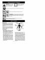 2
2
-
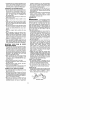 3
3
-
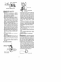 4
4
-
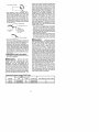 5
5
-
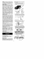 6
6
-
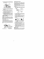 7
7
-
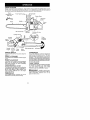 8
8
-
 9
9
-
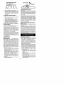 10
10
-
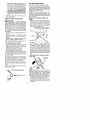 11
11
-
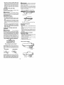 12
12
-
 13
13
-
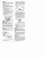 14
14
-
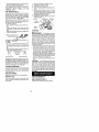 15
15
-
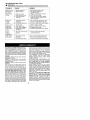 16
16
-
 17
17
-
 18
18
-
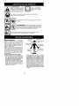 19
19
-
 20
20
-
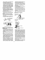 21
21
-
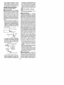 22
22
-
 23
23
-
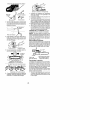 24
24
-
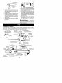 25
25
-
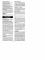 26
26
-
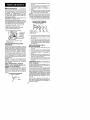 27
27
-
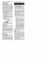 28
28
-
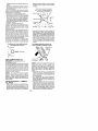 29
29
-
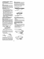 30
30
-
 31
31
-
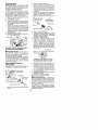 32
32
-
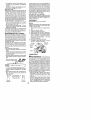 33
33
-
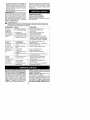 34
34
-
 35
35
-
 36
36


Poulan 220LE El manual del propietario
- Categoría
- Motosierras inalámbricas
- Tipo
- El manual del propietario
- Este manual también es adecuado para
en otros idiomas
- English: Poulan 220LE Owner's manual
Artículos relacionados
-
Poulan Pro 2050 El manual del propietario
-
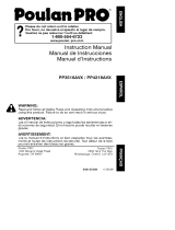 Poulan Pro PP4218AVX El manual del propietario
-
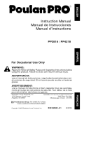 Poulan Pro PP4218 TYPE 1 El manual del propietario
-
 Poulan Pro 3450 El manual del propietario
-
Poulan 2155 El manual del propietario
-
 Poulan Pro PP4620AVL El manual del propietario
-
Poulan Pro 2450 LE El manual del propietario
-
 Poulan Pro PP4620AVHD El manual del propietario
-
Poulan PP3816AV TYPE 1 El manual del propietario
-
Poulan Pro P3314WSA TYPE 1 El manual del propietario


