
28A
24A
bi-amped, active
loudspeaker systems

28A - 24A bi-amped, active loudspeaker systems
ITALIANO 3 - 8
ENGLISH 9 - 14
DEUTSCH 15 - 20
FRANÇAIS 21 - 26
ESPAÑOL 27 - 32
APPENDIX 33 - 42
SAFETY INSTRUCTIONS 43 - 45
July 2009

28A - 24A bi-amped, active loudspeaker systems
__________________________________________
__________________________________________
__________________________________________
__________________________________________
__________________________________________
__________________________________________
__________________________________________
__________________________________________
__________________________________________
__________________________________________
__________________________________________
INDICE
Introduzione
Descrizione
Pannello controlli e connessioni
Importante !!!
Appendice:
Dati tecnici
Curva di risposta
Schema a blocchi
Connettori
Esempi di collegamento
Parti di ricambio
4
4
5
6 - 8
33 - 43
34
35
36
37
38 - 40
41 - 42
ITALIANO
ITALIANO
3
Il lampo con la freccia inserito in un triangolo equilatero avvisa l'utilizzatore della presenza
di tensione pericolosa, senza isolamento, all'interno dell'apparecchio che potrebbe essere
sufcientemente alta da generare il rischio di scossa elettrica.
Il punto esclamativo inserito in un triangolo equilatero avvisa l'utilizzatore della presenza di
importanti istruzioni per l'utilizzo e per la manutenzione.
CONTENUTO DELL’IMBALLO
Sistema attivo biamplicato
Connettore PowerCon
®
Manuale istruzioni
Certicato di garanzia
Dichiarazione di conformità CE
IMPORTANTE ! Norme di sicurezza
ATTENZIONE
Nell'interesse della propria e della altrui sicurezza, e per non invalidare
la garanzia, si raccomanda una attenta lettura di questa sezione prima di
utilizzare il prodotto.
- Questo apparecchio è stato progettato e costruito per venire utilizzato come sistema
di altoparlanti con amplicatore nel contesto tipico di un sistema di amplicazione
sonora e/o di un sistema di registrazione sonora. L'utilizzo per scopi diversi da questi
non è contemplato dal costruttore, ed avviene pertanto sotto la diretta responsabilità
dell'utilizzatore/installatore.
- Questo apparecchio è conforme alla Classe di isolamento I (è necessario il
collegamento alla terra di protezione).
PER EVITARE IL RISCHIO DI INCENDIO E/O DI FOLGORAZIONE:
• Non esporre il prodotto alla pioggia, non utilizzarlo in presenza di elevata umidità
o vicino all'acqua. Non lasciare penetrare all'interno dell'apparecchio alcun liquido,
né alcun oggetto solido. In caso ciò avvenga, scollegare immediatamente
l'apparecchio dalla rete elettrica e rivolgersi ad un servizio di assistenza qualicato
prima di adoperarlo nuovamente. Non appoggiare candele accese od altre sorgenti
di amma nuda sopra l'apparecchio.
• Prima di collegare l'apparecchio alla rete elettrica assicurarsi che la tensione
corrisponda a quella indicata sull'apparecchio stesso.
• Collegare questo apparecchio esclusivamente ad una presa di corrente dotata
di contatto di terra, rispondente alle norme di sicurezza vigenti, tramite il cavo di
alimentazione in dotazione. Nel caso in cui il cavo necessiti di sostituzione, utilizzare
esclusivamente un cavo di identiche caratteristiche.
• L'apparecchio è collegato alla rete anche quando l'interruttore di rete è in posizione
'0' (spento) e la spia luminosa è spenta. All'interno sono presenti potenziali elettrici
pericolosi. Prima di qualunque intervento di manutenzione, scollegare il cavo di
alimentazione dalla presa di rete.
• Non appoggiare alcun oggetto sul cavo di alimentazione. Non posarlo dove possa
costituire intralcio e causare inciampo. Non schiacciarlo e non calpestarlo.
• Installare questo apparecchio prevedendo ampio spazio circostante per un'abbon-
dante circolazione d'aria, necessaria al raffreddamento. Non ostruire le aperture o
le prese d'aria presenti sull'apparecchio. Lasciare spazio sufciente per accedere alla
presa di alimentazione elettrica e al connettore di rete sul pannello posteriore.
• In caso di sostituzione del fusibile esterno, utilizzare esclusivamente un fusibile di
caratteristiche identiche, come riportato sull'apparecchio.
• Prima di effettuare qualsiasi operazione di collegamento, assicurarsi che l'interruttore
di accensione dell'apparecchio sia in posizione '0'.
• Prima di effettuare qualsiasi spostamento del prodotto già installato o in funzione,
rimuovere tutti i cavi di collegamento.
• Per scollegare l'apparecchio dalla rete elettrica, non tirare mai lungo il cavo, ma
afferrarlo sempre per il connettore.
ATTENZIONE!
Questo apparecchio non contiene parti interne destinate all'intervento
diretto da parte dell'utilizzatore. Per evitare il rischio di incendio e/o
folgorazione, non smontarlo e non rimuovere il pannello posteriore.
Per qualsiasi intervento di manutenzione o riparazione, rivolgetevi alla
Elettronica Montarbo srl e/o a personale altamente qualicato
specicamente segnalato da questa.
- Nel predisporre l'apparecchio all'utilizzo, assicurarsi che la forma e la portata
della supercie di appoggio siano idonee a sostenerlo. Nel caso si desideri installare
la cassa su di un'asta di supporto, utilizzarne una di portata adeguata al peso del
prodotto, inserendola nell'apposito adattatore. Qualora si desideri sospendere il
sistema, accertarsi che vengano rispettate le prescrizioni riportate a pag. 7.
- Per evitare urti, calci, inciampi, riservate come luogo per l'istallazione del prodotto
un'area protetta inaccessibile a personale non qualicato. Qualora l'apparecchio
venga utilizzato in presenza di bambini e animali, si rende necessaria una strettissima
sorveglianza.
- Questo prodotto è in grado di generare pressioni acustiche molto elevate, pericolose
per la salute del sistema uditivo. Evitarne quindi l'utilizzo ad elevati livelli acustici se il
pubblico si trova eccessivamente vicino al prodotto (almeno ad 1 m di distanza).
Non esporre i bambini a forti sorgenti sonore.

28A - 24A bi-amped, active loudspeaker systems
Descrizione
4
ITALIANO
A Tromba a direttività costante (dispersione 60° H x 40° V) accoppiata
ad un driver a compressione da 2" in neodimio; bobina mobile
(da 4" per W28As, da 3" per W24As ) in piattina di
alluminio, centratore in kapton, diaframma in titanio.
B W28As: 2 woofer da 15", con magnete in neodimio.
W24As: 2 woofer da 12", con magnete in neodimio.
C Costruzione in multistrato di betulla ad incollaggio fenolico,
rinforzata internamente con angolari di acciaio.
D Griglia in acciaio (verniciatura epossidica).
E Tubi di accordo.
F Pratiche maniglie laterali per il trasporto.
G Pannello controlli e connessioni.
H Adattatore per asta di supporto.
I W28As / W24As: Binari per anelli di ancoraggio standard che con
sentono la sospensione della cassa.
L W28As / W24As: Anelli ad incasso che consentono di regolare
l'inclinazione della cassa sospesa.
W28As / W24As
POWER
I
0
SERIAL N.
FUSE
F 6,3AL
MAINS LINKMAINS INPUT
230V 50/60Hz
( 10K 0,775V RMS )
INOUT LINK
XLR BAL.
1 = GND
2 = HOT
3 = COLD
VOL.
100
H.F.
100
processor controlled active speaker system
1200W (900+300)
2A8
POUR ÉVITER TOUT RISQUE DE CHOC
ELECTRIQUE, NE PAS OUVRIR
POUR ÉVITER TOUT RISQUE DE FEU TOUJOURS REMPLACER
LE FUSIBLE PAR UN DE MÊMES CARACTERISTIQUES
CET APPAREIL DOIT ÊTRE RELIÉ A LA TERRE
TO PREVENT RISK OF FIRE ALWAYS REPLACE
FUSES WITH SAME TYPE AND RATING
THIS APPARATUS MUST BE EARTHED
TO PREVENT ELECTRIC SHOCK,
DO NOT REMOVE COVERS
CAUTION !
AVIS !
PUSH
3
12
NEUTRIK
B
L
D
E
H
A
C
G
L
Introduzione
W28As e W24As sono sistemi professionali ad altissime
prestazioni, progettati per rispondere alle situazioni più
impegnative sia del musicista che del service professionale,
rivelandosi ideali per applicazioni che richiedono alta pressione
sonora, massima denizione e suono cristallino.
Ogni sistema incorpora:
Componenti progettati appositamente per le caratteristiche
del sistema e perciò perfettamente integrati con l'elettronica ad
essi dedicata. L'utilizzo di woofer e driver in neodimio
offre la più elevata qualità in un peso estremamente ridotto.
2 amplicatori MosFet in classe AB.
Potenza di uscita:
W28As 900 + 300 W continui, 1200 + 350 W di picco
W24As 800 + 250 W continui, 1100 + 350 W di picco
2 processori indipendenti che ottimizzano la dinamica
e la risposta in frequenza del sistema.
Crossover elettronico attivo ad elevata pendenza
(24dB per ottava, Linkwitz-Riley).
F
I
W28As / W24As

28A - 24A bi-amped, active loudspeaker systems
POWER
I
0
SERIAL N.
FUSE
F 6,3AL
MAINS LINKMAINS INPUT
230V 50/60Hz
( 10K 0,775V RMS )
INOUT LINK
XLR BAL.
1 = GND
2 = HOT
3 = COLD
VOL.
100
H.F.
100
processor controlled active speaker system
1200W (900+300)
2A8
POUR ÉVITER TOUT RISQUE DE CHOC
ELECTRIQUE, NE PAS OUVRIR
POUR ÉVITER TOUT RISQUE DE FEU TOUJOURS REMPLACER
LE FUSIBLE PAR UN DE MÊMES CARACTERISTIQUES
CET APPAREIL DOIT ÊTRE RELIÉ A LA TERRE
TO PREVENT RISK OF FIRE ALWAYS REPLACE
FUSES WITH SAME TYPE AND RATING
THIS APPARATUS MUST BE EARTHED
TO PREVENT ELECTRIC SHOCK,
DO NOT REMOVE COVERS
CAUTION !
AVIS !
PUSH
3
12
NEUTRIK
5
Pannello controlli e connessioni
ITALIANO
3
4
5
76
1
2
Il pannello controlli e connessioni è uguale per tutti e tre i modelli.
1 I sistemi acustici W28As e W24As sono dotati di prese XLR maschio
(OUT) e femmina (IN) collegate in parallelo: ciò semplica il collegamento
di più sistemi.
uscita mixer ingresso sistema acustico (presa 'IN')
uscita sistema acustico (presa 'OUT') ingresso del sistema da
collegare in parallelo (presa 'IN').
Vedere "connettori" ed "esempi di collegamento" alle pagine
19, 20, 21 e 22.
2 Volume generale (VOL). Permette di regolare i livelli di ingresso dei
2 nali di potenza incorporati, per adattarli al livello di uscita del mixer.
3 Volume delle frequenze alte (H.F.).
N.B: se utilizzate un mixer Montarbo, o comunque un mixer avente
livello di uscita 0dB, per un rendimento ottimale consigliamo di regolare
entrambi questi due volumi al massimo (in senso orario).
4 Interruttore di rete (I/0).
5 Portafusibile con fusibile incorporato.
6 Connettore di alimentazione PowerCon
®
tipo A (di colore blu), che
garantisce un contatto afdabile anche in presenza di forti vibrazioni.
Utilizzare solamente un cavo di alimentazione dotato di conduttore di
terra e riportante i marchi di sicurezza applicabili nel paese di impiego,
con conduttori di sezione adeguata alla corrente assorbita e spina di
alimentazione certicata per questo valore di corrente.
Per le istruzioni di cablaggio del connettore, fare riferimento a pag. 8.
Nell'installazione del diffusore, accertarsi che sia possibile accedere
facilmente a questo connettore e alla presa di alimentazione elettrica.
7 Connettore PowerCon
®
tipo B (di colore grigio) che permette il
collegamento (link) alla rete elettrica di altre apparecchiature
(max. 13,7A disponibili).
ATTENZIONE: la corrente massima che il connettore di alimentazione
PowerCon (6) può trasportare è pari a 20A. La corrente massima che
può essere fornita dal connettore 'AC LOOP OUT' (7) è pari a 13,7A.
Nel caso venga utilizzato il connettore 'AC Loop Out' (7) per
alimentare altre apparecchiature, è responsabilità dell'utente
vericare che:
- questo valore massimo di assorbimento non sia superato,
- l'assemblaggio del cordone di rete sia effettuato da personale
specializzato seguendo le regole impiantistiche nazionali.
Esempio:
3 W28As assorbono circa 19 A (6,3 A x 3) -> OK (19 A < 20 A)
4 W28As assorbono circa 25 A -> NO !
Nel secondo caso è necessario utilizzare 2 collegamenti di alimentazione
indipendenti (ad esempio: 2 linee che collegano 2 mod. W28As ciascuna).

28A - 24A bi-amped, active loudspeaker systems
Importante !
6
ITALIANO
Cura e manutenzione del prodotto
• Questo prodotto è stato progettato per essere utilizzato in climi
tropicali e particolarmente caldi.
• Non porre sulla cassa sorgenti di amme nude, quali candele accese.
• Posizionare la cassa lontano da fonti di calore (caloriferi o qualsiasi
altro oggetto che produca calore).
• Evitare di esporre la cassa alla radiazione solare diretta, ad eccessive
vibrazioni e ad urti violenti.
• Evitare l'uso ed il deposito dell'apparecchio in ambienti polverosi
o umidi: si eviteranno così cattivi funzionamenti e deterioramento
anticipato delle prestazioni.
• Evitare l'uso dell'apparecchio vicino a fonti di interferenze
elettromagnetiche (monitor video, cavi elettrici di alta potenza).
Ciò potrebbe compromettere la qualità audio.
• Nel caso in cui il sistema venga utilizzato all’aperto fare attenzione
a proteggerlo dalla pioggia.
• Proteggere l'apparecchio dal rovesciamento accidentale di liquidi
o sostanze di qualsiasi tipo. In particolare nelle condizioni di utilizzo
tipiche, prestare la massima attenzione alla collocazione dell'apparec-
chio onde evitare che il pubblico, i musicisti, i tecnici o chicchessia
possa poggiarvi sopra bicchieri, tazze, contenitori di cibo o di bevande,
posacenere o sigarette accese.
• Non togliere la griglia di protezione dalla cassa.
• Per rimuovere la polvere usare un pennello o un sofo d'aria,
non usare mai detergenti, solventi o alcool.
• Avere cura dei cavi di collegamento, avvolgerli evitando nodi
e torsioni.
• Non forzare i connettori ed i comandi.
• Accertarsi che l'interruttore di rete sia in posizione '0' (spento)
prima di effettuare qualsiasi collegamento.
• All’interno dell’apparecchio possono essere presenti potenziali elettrici
pericolosi anche quando l’interruttore di rete è in posizione '0' (spento)
e la spia luminosa è spenta. Prima di qualunque intervento di
manutenzione, scollegare il cavo di alimentazione dalla presa di rete
Collegamento alla rete
• Accertarsi che l'interruttore di rete sia in posizione "0".
• Accertarsi che la tensione di alimentazione corrisponda a quella
indicata sul pannello.
• Collegare il cavo di alimentazione ad una presa di corrente dotata
di contatto di terra di sicura efcienza. Utilizzare solamente il cavo di
alimentazione fornito con l’apparecchio o un altro dotato di contatto di
terra e riportante i marchi di sicurezza applicabili nel paese di impiego.
• Lasciare spazio sufciente per accedere alla presa di alimentazione
elettrica e al connettore di rete sul pannello posteriore.
All’interno dell’apparecchio possono essere presenti potenziali elettrici
pericolosi anche quando l’interruttore di rete è in posizione '0' (spento)
e la spia luminosa è spenta. Prima di qualunque intervento di
manutenzione, scollegare il cavo di alimentazione dalla presa di rete.
Collegamento al mixer
Se il mixer ha uscite bilanciate XLR: utilizzare dei normali connettori
XLR bilanciati.
Se il mixer ha uscite sbilanciate XLR e non è un Montarbo: è bene
accertarsi che le uscite XLR del mixer siano sbilanciate a norme IEC 268 e
cioé 1 = massa (GND), 2= caldo (HOT), 3=massa (GND).
Se il mixer ha uscite JACK bilanciate (Jack stereo): è possibile
utilizzare adattatori Jack stereo-XLR bilanciati, a norme IEC 268 e cioé
pin 1 = massa, pin 2 = punta, pin 3 = anello.
Se il mixer ha uscite JACK sbilanciate (Jack mono): è possibile
utilizzare adattatori Jack-XLR maschio sbilanciati a norme IEC 268 e
cioé pin 1 = massa, pin 2 = punta, pin 3 = massa.
Vedere "connettori" a pagina 37.
• Utilizzare sempre solo cavi SCHERMATI (cavi di segnale) di adeguata
sezione e di buona qualità.
• Prima di effettuare i collegamenti tra casse attive e mixer accertarsi
che tutti gli interruttori di rete siano spenti (0).
In tal modo si eviteranno fastidiosi rumori e picchi di segnale talvolta
pericolosi per le casse stesse.
Collegamento in parallelo di più sistemi
• Utilizzare sempre cavi SCHERMATI (cavi di segnale) di adeguata
sezione e di buona qualità. Collegare l’uscita (LINK OUT) del primo
sistema all’ingresso (LINK IN) del secondo, l’uscita (LINK OUT) del
secondo all’ingresso (LINK IN) del terzo ecc.
Vedere "esempi di collegamento" a pagina 38.

28A - 24A bi-amped, active loudspeaker systems
Sensibilità e clipping. Come evitare il clipping.
Ogni sistema amplicatore-altoparlante è caratterizzato da una
sensibilità di ingresso. La sensibilità è denita come il valore del segnale
di ingresso all'amplicatore che produce la massima potenza in uscita.
Aumentando il segnale oltre tale valore, infatti, non si ottiene una
maggiore potenza di uscita, ma soltanto un fenomeno di distorsione
detto 'clipping' (saturazione).
In questa situazione l'altoparlante lavora in modo improprio. Si hanno
delle sovraescursioni e una dissipazione anomala nella bobina mobile,
che si surriscalda e può rompersi. I processori attivi possono evitare solo
parzialmente il clipping, abbassando il guadagno dell'amplicatore.
È possibile, in casi estremi, oltrepassare anche questo tipo di protezione.
Ciò che il processore non può modicare è un'onda che arrivi già
distorta in ingresso all'amplicatore.
Gli effetti di un segnale di questo tipo sono gli stessi descritti sopra.
Come evitare il clipping
Il metodo più semplice sta nel controllare i livelli della catena del segna-
le. Partendo dal canale del mixer bisogna impostare i controlli (gain ed
equalizzatori) in modo tale che il VU-meter del PFL non oltrepassi mai
(o solo occasionalmente) gli 0dB o, in mixer più semplici, che la spia
'clip' o 'peak' non si accenda mai (o solo occasionalmente).
Se si oltrepassano tali livelli occorre diminuire il gain del canale.
Una volta impostato il giusto mix, bisogna fare attenzione ad imposta-
re il livello di uscita in modo tale che il VU-meter non oltrepassi mai il
livello della sensibilità di ingresso della cassa amplicata o del nale di
potenza. Nel caso dei modelli W28As e W24As la sensibilità di ingresso
è 0dB .
7
ITALIANO
Importante !
Sospensione dei sistemi
W28As - W24As
Incorporano su entrambi i lati un binario per anello di ancoraggio
standard per la sospensione del cabinet e sulla parte posteriore 2 anelli
ad incasso che ne consentono l'inclinazione secondo le necessità.
W28As - W24As
Ricordare sempre che nel caso di installazione sospesa, questa
deve avvenire sotto la responsabilità dell'installatore, nel rispetto
di tutte le precauzioni e le norme di sicurezza applicabili nel caso
specico. Non è possibile fornire regole e consigli dettagliati
e validi per tutti i casi, ma ricordiamo che, per la sicurezza
dell'installazione, occorre seguire alcune precauzioni importanti:
1 - Per la sospensione, utilizzare accessori (conformi alle nome
di sicurezza applicabili nel paese di impiego) il cui produttore
ne dichiari e ne garantisca la portata.
2 - Non usare un solo accessorio per la sospensione (ad esempio,
una sola catena), ma almeno due, di portata adeguata. In caso di
rottura di uno di essi, l’altro sarà in grado di sostenere il sistema.
3 - Non agganciare mai un diffusore a quello superiore. Ogni
diffusore deve essere agganciato ai sostegni autonomamente.
4 - Vericare sempre che la struttura cui i diffusori sono sospesi
sia in grado di sopportarne il peso, anche in condizioni avverse.
Considerare l’effetto di altri carichi (ad esempio, il vento nelle
installazioni all’aperto).

28A - 24A bi-amped, active loudspeaker systems
connettore chiuso
corpo
bussolaserracavo
cavo
morsetti
vista interna
inserto
fili
cavo
fili
20 mm
8 mm
Importante !
8
ITALIANO
Inserimento Disinserimento
Cablaggio del cavo di alimentazione sul
connettore PowerCon
®
(fornito con l'apparecchio).
L'assemblaggio del cordone di rete deve essere effettuato da personale
specializzato seguendo le regole impiantistiche nazionali.
Spelare il cavo per una lunghezza di 20 mm ed ogni singolo lo per una
lunghezza di 8 mm. Consigliamo l'utilizzo di un cavo di alimentazione
con conduttori aventi sezione di almeno 2,5 mm
2
(i morsetti dell'in-
serto possono comunque portare un cavo con li aventi sezione no a
4mm
2
/12AWG).
Inlare il cavo prima nella bussola poi nel serracavo (bianco per un cavo
con diametro 5÷11mm; nero per un cavo con diametro 9.50 ÷ 15mm).
Effettuare i collegamenti dei conduttori ai morsetti dell'inserto.
I conduttori potranno essere serrati nei morsetti oppure saldati, facendo
però sempre attenzione ai simboli che compaiono sul connettore stesso:
L (Line - corrispondente al lo di colore marrone),
N (Neutro - corrispondente al lo di colore azzurro) e
(Terra - corrispondente al lo di colore giallo e verde).
Effettuati i collegamenti dei li sull'inserto inlare il cavo nel corpo e
avvitare quest'ultimo alla bussola utilizzando una chiave da 3/4"con
una coppia di serraggio minima pari a 2,5Nm.
Il cavo utilizzato per il cablaggio deve essere conforme alle normative
vigenti nel paese di utilizzo. La sezione minima dei conduttori è:
2,5mm
2
per cavo collegato al connettore NC3 MPA (AC Line In)
1,5mm
2
per cavo collegato al connettore NC3 MPB (AC Loop Out)
La spina di corrente sul lato opposto deve essere certicato per una
corrente pari almeno a 20A (es: IEC309 32 A).
Quando, per qualunque motivo, il cavo di alimentazione risulta danneg-
giato, occorre provvedere alla sua riparazione prima di riutilizzarlo.
Per la sostituzione del cavo:
1 - scollegare il cavo completamente
2 - svitare la bussola (chiave 3/4")
3 - mediante cacciavite, scollegare i 3 conduttori dal connettore.
4 - rimuovere serracavo e bussola dal cavo
5 - utilizzando un nuovo cavo conforme ai requisiti indicati, procedere
al montaggio del connettore (vedi sopra)
ATTENZIONE:
- Prima di collegare e/o scollegare il connettore Powercon, è necessario
spegnere tutte le apparecchiature alle quali è collegato il cavo e
disconnettere il cavo dalla rete elettrica.
- Occorre utilizzare sempre questa procedura anche quando si procede
allo spostamento delle casse.
Per scolegare o collegare il connettore operare come indicato nel dise-
gno qui a lato.

28A - 24A bi-amped, active loudspeaker systems
__________________________________________
__________________________________________
__________________________________________
__________________________________________
__________________________________________
__________________________________________
__________________________________________
__________________________________________
__________________________________________
__________________________________________
__________________________________________
10
10
11
12 - 14
33 - 43
34
35
36
37
38 - 40
41 - 42
ENGLISH
9
ENGLISH
INDEX
Introduction
Description
Control and connection panel
Important !!!
Appendix
Technical Specications
Response curve
Block diagram
Connectors
Connection examples
Spare parts
The lighting ash with arrowhead symbol within an equilateral triangle, is intended to alert
the user to the presence of uninsulated 'dangerous voltage' within the product's enclosure,
that may be of sufcient magnitude to constitute a risk of electric shock to humans.
The exclamation point within an equilateral triangle, is intended to alert the user to the
presence of important operating and maintenance (servicing) instructions.
PACKAGE CONTENTS
Bi-amplied active system
PowerCon
®
connector
Owner’s manual
Warranty certicate
CE declaration of conformity
IMPORTANT ! SAFETY INSTRUCTIONS
WARNING
In order to protect your own and others' safety and to avoid invalidation
of the warranty of this product, please read this section carefully
before operating this product.
- This product has been designed and manufactured for being operated as active
speaker system in the applications tipical of a sound reinforcement system or of a
sound recording system. Operation for purposes and applications other than these
has not been covered by the manufacturer in the design of the product, and is
therefore to be undertaken at end user's and/or installer's sole risk and responsability.
- This unit conforms to Class I insulation, and for safe use it is required that the
protective earth contact is connected to a grounded (earthed) outlet.
TO AVOID THE RISK OF FIRE AND/OR ELECTRIC SHOCK:
• Never expose this product to rain or moisture, never use it in proximity of water
or on a wet surface. Never let any liquid, as well as any object, enter the product.
In case, immediately disconnect it from the mains supply and refer to servicing before
operating it again. Never place burning candles or other sources of open ame on
top of the device.
• Before connecting this product to the mains supply, always make sure that the
voltage on the mains outlet corresponds to that stated on the product.
• This product must be connected only to a grounded mains outlet complying to
the safety regulations in force via the supplied power cable. In case the power cable
needs to be substituted, use exclusively a cable of the same type and characteristics.
• This device is connected to the power line even when the mains switch is in the
O (off) position and the power indicator is off. As long as it is plugged in there are
dangerous electrical potentials inside the device, so, before undertaking any sort of
maintenance work etc., always make sure it has been unplugged from the mains
socket.
• Never place any object on the power cable. Never lay the power cable on a
walkway where one could trip over it. Never press or pinch it.
• Never install the product without providing adequate airow to cool it.
Never obstruct the air intake openings on it. Leave enough room to get to the
mains power socket and the mains connector on the back panel.
• In case the external fuse needs replacement, substitute it only with one of the
same type and rating, as stated on the product.
• Always make sure the Power switch is in its '0' (= off) position before doing any
operation on the connections of the product.
• Before attempting to move the product after it has been installed, remove all
the connections.
• To disconnect the power cable of this product from the mains supply never pull
the cable directly. Hold the body of the plug rmly and pull it gently from the mains
supply outlet.
CAUTION!
This product does not contain user serviceable parts.
To prevent re and/or electrical shock, never disassemble it or
remove the rear panel. For maintenance and servicing always
refer to the ofcial Montarbo Distributor in your Country or
to qualied personnel specically authorised by the Distributor.
- Before placing the product on a surface of any kind, make sure that its shape and
load rating safely match the product size and weight. When installing the speaker
system on a stand, use a stable stand that will t in the adapter and may carry the
loudspeaker weight.
If you wish to suspend the system, follow the directions at page 13.
- To avoid shocks, kicks, or whatever action, always reserve a protected area with
no access to unqualied personnel as installation site of the product.
In case the product is used near children and animals closest supervision is necessary.
- This product can generate very high acoustic pressures which are dangerous for the
hearing system. Always avoid operation at loud levels if anyone is excessively near to
the product (at least 1 m of distance).
Never expose children to high sound sources.

28A - 24A bi-amped, active loudspeaker systems
10
ENGLISH
Introduction
Ideally suited to applications requiring high sound pressure
levels, maximum denition and clean sound, W28As and W24A
professional loudspeaker systems provide outstanding sound
performance in the most diverse situations
Each system is equipped with:
The custom made neodymium-based transducers combine high
performance with great weight saving and operate in complete
synergy with the dedicated electronic circuitry.
Two class A-B MosFet power ampliers.
Output powers:
W28As 900 + 300 W continuous, 1200 + 350 W peak
W24As 800 + 250 W continuous, 1100 + 350 W peak
Two independent processors optimize the dynamic range
and the frequency response of the system.
High slope active crossover lter (24dB/oct Linkwitz-Riley).
A Constant directivity, high frequency horn (dispersion 60°H x 40°V)
with 2" neodymium compression driver featuring (4" in W28As,
3" in W24As) aluminum at wire voice coil, kapton
former, titanium dome.
B W28As: 2 x 15" woofers with neodymium magnet
W24As: 2 x 12" woofers with neodymium magnet
C High grade phenyl-glued multiply birch construction, reinforced
with internal steel braces.
D Powder coated, perforated steel grid.
E Tuning ports.
F Side transport handles.
G Controls and connections panel.
H Speaker stand adaptor.
I W28As / W24As: Industry standard aluminium y-track suspension
system.
L W28As / W24As: Recessed rings, for tilt adjustment of the
suspended speaker.
Description
W28As / W24As
POWER
I
0
SERIAL N.
FUSE
F 6,3AL
MAINS LINKMAINS INPUT
230V 50/60Hz
( 10K 0,775V RMS )
INOUT LINK
XLR BAL.
1 = GND
2 = HOT
3 = COLD
VOL.
100
H.F.
100
processor controlled active speaker system
1200W (900+300)
2A8
POUR ÉVITER TOUT RISQUE DE CHOC
ELECTRIQUE, NE PAS OUVRIR
POUR ÉVITER TOUT RISQUE DE FEU TOUJOURS REMPLACER
LE FUSIBLE PAR UN DE MÊMES CARACTERISTIQUES
CET APPAREIL DOIT ÊTRE RELIÉ A LA TERRE
TO PREVENT RISK OF FIRE ALWAYS REPLACE
FUSES WITH SAME TYPE AND RATING
THIS APPARATUS MUST BE EARTHED
TO PREVENT ELECTRIC SHOCK,
DO NOT REMOVE COVERS
CAUTION !
AVIS !
PUSH
3
12
NEUTRIK
B
L
D
E
H
A
B
C
G
L
F
I
W28As / W24As

28A - 24A bi-amped, active loudspeaker systems
11
ENGLISH
POWER
I
0
SERIAL N.
FUSE
F 6,3AL
MAINS LINKMAINS INPUT
230V 50/60Hz
( 10K 0,775V RMS )
INOUT LINK
XLR BAL.
1 = GND
2 = HOT
3 = COLD
VOL.
100
H.F.
100
processor controlled active speaker system
1200W (900+300)
2A8
POUR ÉVITER TOUT RISQUE DE CHOC
ELECTRIQUE, NE PAS OUVRIR
POUR ÉVITER TOUT RISQUE DE FEU TOUJOURS REMPLACER
LE FUSIBLE PAR UN DE MÊMES CARACTERISTIQUES
CET APPAREIL DOIT ÊTRE RELIÉ A LA TERRE
TO PREVENT RISK OF FIRE ALWAYS REPLACE
FUSES WITH SAME TYPE AND RATING
THIS APPARATUS MUST BE EARTHED
TO PREVENT ELECTRIC SHOCK,
DO NOT REMOVE COVERS
CAUTION !
AVIS !
PUSH
3
12
NEUTRIK
Control and connection panel
3
4
5
76
1
2
Controls and connections are the same for the three models.
1 The W28As and W24As speaker systems are equipped with XLR
male (OUT) and female (IN) parallel connected sockets allowing
easier daisy-chaining.
Mixer output Input ('IN' socket) of the speaker system
Output ('OUT' socket) of the speaker system Input ('IN' socket) of
the speaker system to be connected in parallel.
See 'connectors' and 'connection examples' at pages 19, 20, 21
and 22.
2 Main volume (VOL). Adjusts the input levels of the two built-in
ìpower ampliers to adapt them to the output level of the mixer.
3 High frequencies level control (H.F.).
Note: if you are using a Montarbo mixer (or any mixer having an
output level of 0dB) for optimum performance it is advisable to set
both controls fully clockwise (to their maximum settings).
4 POWER / 0 - I: Mains power on/off switch.
5 Fuse holder with built-in fuse.
6 Mains supply inlet socket with type A PowerCon
®
(blue) connector,
which guarantees a reliable, vibration-proof contact. Use only a mains
cable with suitable conductors capable of handling the current involved,
equipped with a ground conductor, marked with the applicable, country
specic, safety approvals and tted with a power plug certied for the
actual current value. Refer to page 14 for connector wiring instructions.
When installing make sure that it is easy to get to this socket and to the
mains plug.
7 Power 'AC LOOP OUT' socket (type B gray PowerCon
®
connector)
that allows you to link other devices to the mains power (max. current
available: 13.7 A).
CAUTION
The power supply PowerCon® socket (6) is rated for a 20 A maximum
current. The maximum current that may be sourced from the
'AC LOOP OUT' socket is 13.7 A.
If the 'AC LOOP OUT' (7) socket is used to supply power to other
devices, it is the user's responsibility to verify that:
- this maximum current drain is not exceeded,
- the power cord assembly is made by a qualied techncian in
compliance with the national regulations in force for electrical
systems.
Example:
Three model W28As speakers have a maximum current drain of about
19 A (6.3 A x 3) > OK (19 A < 20 A).
Four model W28As speakers have a maximum current drain of about
25 A (6.3 A x 4) > NOT OK!
In this case you must use two independent power supply cables.
(two lines, each powering two W28As).

28A - 24A bi-amped, active loudspeaker systems
Important !
12
ENGLISH
Product care and maintenance
• This product has been designed for use in tropical climates and
particularly warm weather conditions.
• Never place burning candles or other sources of open ame on top
of the device.
• Never expose the enclosure to heat sources (heaters or other
products that produce heat).
• Never expose the enclosure to direct sunlight, excessive vibrations
or mechanical shocks.
• Avoid operating and storing the enclosure in damp or dusty places:
this may lead to malfunctions and premature degrading of specications.
• Avoid using the enclosure close to strong sources of electromagnetic
interferences (e.g. video monitors, high power electrical cabling).
This may lead to degradation of audio quality.
• When setting up the system up outdoors, be sure to protect it
against rain.
• Care should be taken so that objects do not fall and liquid is not
spilled onto the enclosure. In public event don't let people, musicians,
technicians or anyone put glasses, cups, ashtrays or cigarettes on the
enclosure.
• Always leave the protective grid mounted on the enclosure.
• Use a soft brush or a jet of air to clean the enclosure. Do not use
alcohol, solvents or detergents.
• Take care of your connector cables. Make sure that they are not
damaged, knotted or twisted.
• Do not force connectors and controls.
• Make sure the mains power switch is off ('0') before starting any con-
nection.
• As long as it is plugged in there can be dangerous electrical potentials
inside the device, so, before undertaking any sort of maintenance work
etc., always make sure it has been unplugged from the mains socket.
Mains power connection
• Make sure the mains power switch is off ('0').
• Check that mains voltage corresponds to the voltage indicated
on the panel, under the mains socket.
• Use only the factory supplied mains cable or, if a different plug style
is needed, a suitable cable with a ground connection and marked with
the safety approvals valid in the country of use.
• Leave enough room to get to the mains power socket and the mains
connector on the back panel.
As long as it is plugged in there can be dangerous electrical potentials
inside the device, even when the mains switch is in the '0' (off) position
and the power indicator is off so, before undertaking any sort of
maintenance work etc., always make sure it has been unplugged from
the mains socket
Connection to the mixer
If the mixer has XLR balanced outputs: use standard balanced XLR
connectors.
If the mixer has XLR unbalanced outputs: in this case, unless using
a Montarbo mixer, make sure that the XLR outputs on the mixer are
unbalanced to IEC 268 standard 1 = GND, 2 = HOT, 3 = GND.
If the mixer has JACK balanced outputs (stereo jacks): it is
possible to use stereo jack-XLR adapters, wired according to IEC 268
pin 1 = ground (sleeve), pin 2 = tip, pin 3 = ring.
If the mixer has JACK unbalanced outputs (mono jacks):
use suitable Jack-XLR male adapters unbalanced according to IEC 268
pin 1 = ground, pin 2 = tip, pin 3 = ground.
See 'connectors' at page 37.
• Always use only heavy gauge, high quality SHIELDED cables
(signal cables).
• Always make sure that the mixer and the powered enclosures are
switched off before connecting them.
This will to avoid annoying noises and signal peaks, which can also be
dangerous for the enclosures themselves.
Parallel connection of two or more systems
• Always use only heavy gauge, high quality SHIELDED cables (signal
cables). Connect the LINK OUT socket of the rst system to the LINK IN
socket the second system and the LINK OUT of the second system to
the LINK IN of the third, and so on.
See 'connection examples' at page 38.

28A - 24A bi-amped, active loudspeaker systems
Input sensitivity and clipping. How to avoid clip-
ping
Every amplied speaker system is characterized by a value of input
sensitivity. The sensitivity is dened as the value of the amplier's input
signal that will result in maximum power output. An increase in input
signal over that threshold will result, not in increased power, but in a
distortion phenomenon called 'clipping' (output stage saturation).
In this condition, the speaker will operate improperly. The diaphragm
will exceed it's excursion limits, and the voice coil will overheat beyond
it's thermal limits, resulting in overheating and premature failure.
The active processors will help in avoiding clipping, by reducing the
amplier gain and thus the input sensitivity, but this type of protections
may be overridden in very extreme conditions.
What the active processor cannot modify is a signal that is distorted
before getting to the active speaker's input.
The effects of this type of signal are the same as described above.
How to avoid clipping
The simplest way to avoid clipping is to check each level in the signal's
chain. Start from each input channel of the mixer and adjust the gain
control and the equalizer's controls so that the PFL meter will never (or
only occasionally) indicate more than 0dB. In simpler mixers, check that
the 'clip' or 'peak' indicator is always off, or blinks only occasionally.
If these levels are exceeded, reduce the channel's input gain.
Once the desired mix is obtained, adjust the output level so that it never
exceeds the active speaker's or the power amplier's input sensitivity,
as displayed on the master output VU-meter.
In models W28As and W24As the input sensitivity is 0dB.
13
ENGLISH
Important !
Hanging the speakers. Tips and warnings.
W28As - W24As
Both sides of their cabinet embody a slide guide for standard anchor
ring to allow the loudspeaker suspension.
On the rear side there are
two recessed rings allowing tilt adjustment.
W28As - W24As
Please bear in mind that all hanging installation jobs are carried
out under the sole responsibility of the person doing the actual
work and must be done in full compliance with all the applicable
safety rules and regulations. We do not attempt to provide
detailed guidelines for all the potential ways in which these
extremely exible systems can be installed, but do want to
remind you that to ensure a safe installation, it is necessary
to adhere to the following:
1 - When hanging the speakers, use only means of suspension
(in accordance with the safety regulation valid in the country
of use) having a carrying capacity rated and guaranteed by the
manufacturer.
2 - Never depend on only one means of suspension for hanging
speakers (for example one chain); always use at least two of
them and make sure they are sufciently strong. So, if one fails
the other will sustain the load.
3 - Never hook a speaker to the one above.
Each speaker must be individually hooked to the supports.
4 - Always make sure that the truss structure intended to support
the speakers is sturdy enough to hold their weight, even under
stressful, adverse conditions.
Always consider the effect of additional loads (for example, the
wind in case of outdoor installations).

28A - 24A bi-amped, active loudspeaker systems
Important !
power con
®
connector
housing
bushingchuck
cable
setscrews
inside view
insert
wires
cable
wires
20 mm
8 mm
14
ENGLISH
Plugging Unplugging
Wiring of the power cable for the PowerCon
®
connector (supplied with the unit).
The power cord assembly must be made by a qualied techncian in
compliance with the national regulations in force for electrical systems.
Strip the cable for 20 mm of length and strip each wire for 8 mm of
length. We suggest to use a power cable with 2,5 mm
2
section
wires (the insert terminals can however support a cable with wires up
to a section of 4 mm
2
/12AWG).
Insert the power cable into the bushing and into the chuck (white
chuck for a cable diameter of 5 ÷ 11 mm; black chuck for a cable
diameter of 9.50 ÷ 15 mm). Insert the wires into the terminals and
fasten the clamping device by a at screw driver.
The wire ends can be clamped in or soldered to the terminal, always
paying attention to the symbols shown on the connector:
L (Live - corresponding to the brown wire),
N (Neutral - corresponding to the light blue wire) and
(Ground - corresponding to the yellow and green wire).
Once the wires have been connected to the insert, lead the cable
through the housing and screw down the bushing by means of a 3/4"
fork wrench (min. torque 2.5 Nm / 1.8 lb-ft).
The cable must comply with the applicable, country specic, safety
regulations.
The minimum conductor size must be:
2.5 mm
2
(13 AWG) for the cable wired to the NC3 MPA (AC line in) plug
1.5 mm
2
(15 AWG) for the cable wired to the NC3 MPB (AC loop out)
plug.
The mains power plug on the other end of the cable must be certied
for a current equal to 20A at least (eg: IEC309 32A).
When, for any reason, the power cable show signs of damage, it is
mandatory to replace or repair it before any further use.
To replace the cable:
1 - disconnect the cable at both ends
2 - unscrew the bushing (3/4" wrench)
3 - using a screwdriver, disconnect all three conductors from the insert
4 - remove the chuck and the bushing from the cable
5 - using a new cable, complying with the previous reported require-
ments, proceed with the connector's assembly, as described above.
CAUTION:
- Before plugging and/or unplugging the PowerCon connector, it is
mandatory to switch off all the equipment that is connected to the
cable and to disconnect the cable from AC mains.
- Follow this procedure also when the speakers must be moved.
Operate as illustrated in the side drawing when you have to plug and/or
unplug the connector.

28A - 24A bi-amped, active loudspeaker systems
15
DEUTSCH
Das Blitzsymbol mit Pfeilspitze innerhalb eines gleichschenkligen Dreiecks warnt den
Benutzer vor dem Vorhandensein nicht isolierter gefährlicher Netzspannungen im
Inneren des Geräts, die so stark sein können, dass für Menschen die Gefahr eines
Stromschlags besteht.
Das Ausrufezeichen innerhalb eines gleichschenkligen Dreiecks macht den Benutzer
auf das Vorhandensein wichtiger Betriebs- und Wartungsanleitungen aufmerksam.
WICHTIG ! Sicherheitsvorschriften
ACHTUNG
Im Interesse Ihrer eigenen Sicherheit und der Sicherheit anderer
und um die Garantie nicht zu gefährden, sollte der vorliegende
Abschnitt vor Gebrauch des Produkts aufmerksam gelesen werden.
- Dieses Gerät wurde für den Gebrauch als Aktivlautsprechersystem im Rahmen
typischer Anwendungen von Verstärkungssystemen und/oder Tonaufnahmesystemen
entwickelt und hergestellt. Der Gebrauch zu anderen als den genannten Zwecken ist
vom Hersteller nicht vorgesehen und erfolgt somit unter direkter Verantwortung des
Benutzers/Installateurs.
- Dieses Gerät entspricht der Isolierungsklasse 1 (Schutzerdung ist unbedingt
erforderlich).
Zur Vermeidung der Gefahr von Bränden oder elektrischen Schlägen:
• Dieses Produkt nicht Regen oder Feuchtigkeit aussetzen und nicht in der Nähe von
Wasser betreiben. Verhindern, dass in das Gerät Flüssigkeiten oder Gegenstände
eindringen. Sollte dies dennoch geschehen, unverzüglich das Gerät vom Stromnetz
abnehmen und vor der erneuten Inbetriebnahme durch einen qualizierten Service-
techniker überprüfen lassen. Stellen Sie keine offenen Flammen, beispielsweise
angezündete Kerzen, auf das Gerät.
• Vor dem Anschluss an das Stromnetz sicherstellen, dass die Netzspannung mit der
auf dem Gerät angegebenen Nennspannung übereinstimmt.
• Das Gerät ausschließlich mit dem mitgelieferten Netzkabel an eine Steckdose mit
Schutzkontakt anschließen, die den geltenden Sicherheitsvorschriften entspricht.
Muss das Netzkabel ersetzt werden, ausschließlich ein Netzkabel mit identischen
Eigenschaften verwenden.
• Selbst wenn der Netzschalter sich in der Stellung '0' (aus) bendet, ist das Gerät
nicht vollständig vom Netz getrennt und kann gefährliche elektrische Potentiale
aussenden. Vor jedem Wartungseingriff ist das Gerät vom Stromnetz zu trennen
(Netzkabel ausstecken)
• Zum Ausstecken des Netzkabels aus der Steckdose keinesfalls am Netzkabel ziehen,
sondern das Kabel stets direkt am Stecker anfassen.
• Keine Gegenstände auf dem Netzkabel abstellen. Das Netzkabel so verlegen, dass
es kein Hindernis darstellt und keine Stolpergefahr besteht. Das Netzkabel nicht quet-
schen und nicht darauf treten.
• Bei der Installation genug freien Raum um das Gerät lassen, um eine ausreichende
Luftzirkulation für die Kühlung zu gewährleisten. Die Lüftungs- und Ansaugöffnungen
nicht verdecken. Genug freien Raum lassen um die Steckdose und den Netzstecker
auf der Rückeite zu erreichen.
• Muss die externe Sicherung ausgetauscht werden, ausschließlich eine Sicherung
mit identischen Eigenschaften gemäß den Angaben auf dem Gerät verwenden.
• Vor dem Anschluss des Geräts sicherstellen, dass sich der Ein/Aus-Schalter in
Schaltstellung '0' bendet.
• Vor dem Transport des bereits installierten oder bereits in Betrieb bendlichen
Geräts zunächst alle Anschlusskabel abnehmen.
ACHTUNG!
Dieses Gerät enthält keine Teile, bei denen ein direkter Eingriff seitens des
Benutzers vorgesehen ist. Das Gerät keinesfalls auseinanderbauen oder
die Rückwand abnehmen, um die Gefahr von Bränden und elektrischen
Schlägen zu vermeiden. Für Wartungs- und Reparatureingriffe aller Art
wenden Sie sich stets an das Unternehmen Elettronica Montarbo srl und/
oder qualizierte Fachtechniker, die vom Unternehmen genannt werden.
- Bei der Vorbereitung des Geräts auf den Betrieb sollte sichergestellt werden, dass
die Form und die Tragfähigkeit der Auageäche für die Aufstellung desselben
geeignet sind. Sollte die Lautsprecherbox auf einem Stativ installiert werden, so
sollte dieses hinsichtlich der Tragfähigkeit dem Gewicht des Produktes entsprechend
ausgelegt sein, und in den hierfür vorgesehenen Adapter eingesteckt werden.
Wird das System aufgehängt, müssen die auf Seite 19 aufgeführten
Vorschriften beachtet werden.
- Zur Vermeidung von Stößen, Tritten und sonstigen gewaltsamen Einwirkungen das
Gerät nur an einem geschützten und Unbefugten nicht zugänglichen Ort aufstellen.
Wenn das Gerät in Gegenwart von Kindern oder Haustieren betrieben wird, ist eine
strikte Überwachung erforderlich.
- Dieses Gerät kann sehr hohe Schalldruckwerte erzeugen, die zu Gehörschäden
führen können. Daher sind hohe Lautstärkepegel zu vermeiden, wenn sich das
Publikum in großer Nähe zum Gerät bendet. Sicherstellen, dass ein Abstand von
mindestens 1m zwischen Gerät und Publikum gewährleistet ist.
Niemals Kinder starken Schallemissionen aussetzen !
__________________________________________
__________________________________________
__________________________________________
__________________________________________
__________________________________________
__________________________________________
__________________________________________
__________________________________________
__________________________________________
__________________________________________
__________________________________________
INHALTSVERZEICHNIS
Einführung
Beschreibung
Bedien- und Anschlußfeld
Wichtig !!!
Appendix
Technische Daten
Frequenzkurve
Blockdiagramm
Anschlüsse
Anschlussbeispiele
Ersatzteile
16
16
17
18 - 19
33 - 43
34
35
36
37
38 - 40
41 - 42
DEUTSCH
PACKUNGSINHALT
Aktives Lautsprechersystem
PowerCon
®
Netz Kabelstecker
Bedienungsanleitung
Garantiebescheinigung
EG-Konformitätserklärung

28A - 24A bi-amped, active loudspeaker systems
16
DEUTSCH
Einführung
W28As und W24As wurden für Leistungen auf höchstem
Niveau entwickelt. Beide Systemen stellen die ideale Lösung für
Anwendungen dar, die einen hohen Schalldruck, eine maximale
Auösung und einen kristallklaren Ton erfordern.
Beide Systemen verfügen über:
Nach Montarbo-Angaben speziell gefertigten Komponenten, die
mit der für sie vorgesehenen Elektronik perfekt übereinstimmen.
Sowohl der Tieftöner als auch der Mittel/Hochtontreiber sind aus
NEODYM gefertigt und bieten höchste Qualität bei einem äußert
geringen Gewicht.
2 MosFet-Verstärker der Klasse AB.
Ausgangsleistungen:
W28As 900 + 300 W Dauerleistung, 1200 + 350 W Spitzenleistung
W24As 800 + 250 W Dauerleistung, 1100 + 350 W Spitzenleistung
z
2 unabhängige Prozessoren optimieren den Frequenzgang
und die Dynamik des Systems.
Elektronische aktive Frequenzweiche (24dB/oct., Linkwitz-Riley).
A 2"-Neodym-Kompressionstreiber (Titanmembrane; 4" Schwingspule
bei W28A, 3" Schwingspule bei W22A und W24A) und Horn mit
abgeregeltem Abstrahl (60°H x 40°V).
B W28As: Zwei 15" Hochleistungs-Tieftöner mit Neodymmagnet.
W24As: Zwei 12" Hochleistungs-Tieftöner mit Neodymmagnet
C Konstruktion aus phenolverleimtem Birkenholz, intern verstärkt
mit Stahlwinkeln.
D Stahlgitter mit Epoxydharzbeschichtung.
E Reexöffnungen.
F Praktische seitliche Tragegriffe für den Transport.
G Bedien- und Anschlußfeld.
H Adapter für Hochständer.
I W28As / W24As: Schiene für den Standard-Verankerungsring zur
Aufhängung der Lautsprecherbox.
L W28As / W24As: Versenkter Ring zur Einstellung des
Neigungswinkels der Lautsprecherbox.
Beschreibung
W28As / W24As
POWER
I
0
SERIAL N.
FUSE
F 6,3AL
MAINS LINKMAINS INPUT
230V 50/60Hz
( 10K 0,775V RMS )
INOUT LINK
XLR BAL.
1 = GND
2 = HOT
3 = COLD
VOL.
100
H.F.
100
processor controlled active speaker system
1200W (900+300)
2A8
POUR ÉVITER TOUT RISQUE DE CHOC
ELECTRIQUE, NE PAS OUVRIR
POUR ÉVITER TOUT RISQUE DE FEU TOUJOURS REMPLACER
LE FUSIBLE PAR UN DE MÊMES CARACTERISTIQUES
CET APPAREIL DOIT ÊTRE RELIÉ A LA TERRE
TO PREVENT RISK OF FIRE ALWAYS REPLACE
FUSES WITH SAME TYPE AND RATING
THIS APPARATUS MUST BE EARTHED
TO PREVENT ELECTRIC SHOCK,
DO NOT REMOVE COVERS
CAUTION !
AVIS !
PUSH
3
12
NEUTRIK
B
L
D
E
H
A
B
C
G
L
F
I
W28As / W24As

28A - 24A bi-amped, active loudspeaker systems
DEUTSCH
17
POWER
I
0
SERIAL N.
FUSE
F 6,3AL
MAINS LINKMAINS INPUT
230V 50/60Hz
( 10K 0,775V RMS )
INOUT LINK
XLR BAL.
1 = GND
2 = HOT
3 = COLD
VOL.
100
H.F.
100
processor controlled active speaker system
1200W (900+300)
2A8
POUR ÉVITER TOUT RISQUE DE CHOC
ELECTRIQUE, NE PAS OUVRIR
POUR ÉVITER TOUT RISQUE DE FEU TOUJOURS REMPLACER
LE FUSIBLE PAR UN DE MÊMES CARACTERISTIQUES
CET APPAREIL DOIT ÊTRE RELIÉ A LA TERRE
TO PREVENT RISK OF FIRE ALWAYS REPLACE
FUSES WITH SAME TYPE AND RATING
THIS APPARATUS MUST BE EARTHED
TO PREVENT ELECTRIC SHOCK,
DO NOT REMOVE COVERS
CAUTION !
AVIS !
PUSH
3
12
NEUTRIK
Bedien- und Anschlußfeld
3
4
5
76
Bedienungselemente und Anschluße sind identisch für die drei
Modellen.
1 Das Anschlussfeld jedes Systems verfügt über parallelgeschaltene
XLR-Buchsen - sowohl männlich (OUT) als weiblich (IN) - die den
Anschluss von weiteren Aktivboxen erleichtern.
Ausgang des Mischpults Eingang des Lautsprechersystems
('IN'-Buchse).
Ausgang des Lautsprechersystems ('OUT'-Buchse) Eingang eines
weiteren Systems ('IN'-Buchse).
Siehe Seiten 37, 38, 39, 40 (Anschlusse und
Anschlußbeispiele).
2 Eingangspegelkontrolle (VOL). Damit kann die Eingangs-
empndlichkeit der integrierten Leistungsendstufe an den
Ausgangspegel des Mischpults angepaßt werden.
3 Klangregler (H.F.). Verringert den Höhenanteil des Signals.
N.B: Benutzen Sie ein Montarbo-Mischpult, bzw. ein anderes Mischpult
mit Ausgangspegel 0dB, ist es empfehlenswert diese beiden Lautstärke
auf Maximal einzustellen (im Uhrzeigersinn).
4 Netzschalter (I/0).
5 Sicherungshalter mit Sicherung.
6 Netzverbinder PowerCon
®
(Typ A - blau), der auch bei starken
Vibrationen einen zuverlässigen Kontakt gewährleistet.
Nur ein Netzkabel mit Erdungsleiter und den im jeweiligen Einsatzland
geltenden Sicherheitskennzeichnungen, mit Leitern mit einem dem
aufgenommenen Strom angemessenen Querschnitt und mit einem für
diesen Stromwert zertizierten Stecker verwenden. Für die Anleitung
bezüglich des Netzverbinderanschlusses auf Seite 20 nachlesen.
Bei der Installation darauf achten, dass sowohl der Netzverbinder als
auch die Steckdose leicht erreichbar sind.
7 Netzverbinder PowerCon
®
(Typ B - grau) für die Verbindung (Link)
von anderen Geräten an das Stromnetz (max. 13,7 A verfügbar).
ACHTUNG: Der höchste Stromwert, den der Netzverbinder PowerCon
®
(6) transportieren kann, beträgt 20 A. Der höchste Stromwert, der vom
Netzverbinder 'LINK' (7) geliefert werden kann, beträgt 13,7 A.
Sollte der Verbinder 'LINK' (7) zur Versorgung anderer Geräte
verwendet werden, ist der Benutzer dafür verantwortlich,
Folgendes zu prüfen:
- dass der Höchstwert der Stromaufnahme nicht überschritten
wird.
- dass der Versorgungskreis (elektrische Schalttafel, Netzsteck-
dose, Stecker und Kabel) korrekt dimensioniert ist.
Im Zweifelsfall wenden Sie sich an einen qualizierten Techniker.
Beispiel:
3 W28As nehmen ungefähr 19 A (6,3 A x 3) aus -> OK (19 A < 20 A)
4 W28 nehmen ungefähr 25 A auf -> NEIN!
Im zweiten Fall sind 2 unabhängige Netzverbindungen zu verwenden
(zum Beispiel: 2 Leitungen, die je 2 Mod. W28As verbinden).
1
2

28A - 24A bi-amped, active loudspeaker systems
Pege und Wartung des Geräts
• Die Lautsprecherbox ist entfernt von Wärmequellen (Heizkörpern
oder jedem anderen Gerät, das Wärme produziert) aufzustellen.
• Stellen Sie keine offenen Flammen, beispielsweise angezündete
Kerzen, auf das Gerät.
• Setzen Sie das Gerät nicht für längere Zeit direkter
Sonneneinstrahlung aus. Vermeiden Sie starke Vibrationen und Stöße.
• Die Lautsprecherbox darf nicht in feuchter oder staubiger Umgebung
betrieben oder gelagert werden. Sie darf niemals Regen ausgesetzt
werden. Somit vermeiden Sie Störungen und eine vorzeitige Verschlech-
terung der Leistungen oder gar elektrische Stromschläge bzw. Brand.
• Achten Sie beim Einsatz im Freien darauf, dass Ihr System vor Regen
geschützt aufgestellt wird.
• Vermeiden Sie den Betrieb des Systems in der Nähe von elektro-
magnetischen Störquellen (wie Video-Monitoren, Starkstromkabel etc.).
Dies könnte die Tonqualität beeinträchtigen.
• Keine Gegenstände auf die Lautsprecherbox fallen lassen.
Keine Flüssigkeiten auf die Lautsprecherbox stellen. Achten Sie
besonders darauf, dass keine Gläser, Tassen, Aschenbecher und
Zigaretten auf die Lautsprecherbox gelegt werden.
• Zum Säubern sollte eine weiche Bürste oder Druckluft verwendet wer-
den. Benutzen Sie keine Reinigungs- oder Lösungsmittel oder Alkohol.
• Schutzgitter keinesfalls entfernen.
• Vergewissern Sie sich stets, dass die Kabel intakt sind und
vermeiden Sie das Knoten und Knicken von Kabeln.
• Vermeiden Sie das Anstoßen an die Bedienungselemente.
• Vor dem Anschluss sicherstellen, dass sich der Netzschalter des
Systems in Schaltstellung '0' (aus) bendet.
• Selbst wenn der Netzschalter sich in der Stellung '0' (aus) bendet,
ist das Gerät nicht vollständig vom Netz getrennt und kann gefährliche
elektrische Potentiale aussenden. Vor jedem Wartungseingriff ist das
Gerät vom Stromnetz zu trennen (Netzkabel ausstecken)
Wichtig !
Netzanschluss
• Überprüfen, ob die Netzspannung mit der auf dem Bedienfeld
angegebenen Spannung übereinstimmt.
• Das Netzkabel mit einer Steckdose verbinden, deren Erdung sicher
gewährleistet ist. Nur jenes Kabel verwenden, das zusammen mit
dem Gerät geliefert wurde, ansonsten muß ein Kabel mit Erdungsleiter
verwendet werden, das die im jeweiligen Einsatzland geltenden
Sicherheitskennzeichnungen aufweist.
• Genug freien Raum hinter der Box lassen um die Steckdose und den
Netzstecker auf der Rückseite zu erreichen.
Selbst wenn der Netzschalter sich in der Stellung '0' (aus) bendet, ist
das Gerät nicht vollständig vom Netz getrennt und kann gefährliche
elektrische Potentiale aussenden. Vor jedem Wartungseingriff ist das
Gerät vom Stromnetz zu trennen (Netzkabel ausstecken).
Anschluss an das Mischpult
• Verfügt das Mischpult über symmetrische XLR-Ausgänge,
werden normale Kabel mit symmetrischen XLR-Steckern benutzt.
• Verfügt das Mischpult über unsymmetrische XLR-Ausgänge
und stammt nicht aus dem Haus Montarbo, prüfen Sie vorher, ob
die Ausgänge gemäß der IEC-Norm 268 unsymmetriert sind, d.h.:
1 = Masse (GND), 2 = heiß (HOT), 3 = Masse (GND).
• Verfügt das Mischpult über symmetrische Klinken-Ausgänge
(Stereo-Klinken) werden Kabel mit Adapter-Klinken symmetrischer XLR
benutzt, die gemäß der IEC-Norm 268 symmetriert sind, und zwar:
Pin 1 = Masse, Pin 2 = Spitze, Pin 3 = Ring.
• Verfügt das Mischpult über unsymmetrische Klinken-Ausgänge
(Mono-Klinken), werden Kabel mit Klinken-XLR-Adapter verwendet,
die gemäß der IEC-Norm 268 unsymmetriert sind, und zwar:
pin 1 = Masse, pin 2 = Spitze, pin 3 = Masse.
Siehe Anschlüsse auf Seite 37
• Stets ausschließlich ABGESCHIRMTE Kabel (Signal-Kabel) mit
ausreichendem Querschnitt und von guter Qualität benutzen.
• Sicherstellen, dass sich alle Netzschalter in Position '0' (aus) benden,
bevor die Anschlüsse zwischen den Aktivlautsprechern und dem
Mischpult vorgenommen werden. Auf diese Weise können
unangenehme Geräusche sowie Signalübersteuerungen vermieden
werden, die für die Boxen selbst eine Gefahr darstellen können.
Parallelanschluss mehrerer Systeme
• Stets ausschließlich ABGESCHIRMTE Kabel (Signal-Kabel) mit
ausreichendem Querschnitt und von guter Qualität benutzen.
Den Ausgang (LINK OUT) des ersten Systems an den Eingang (LINK IN)
des zweiten Systems anschließen, den Ausgang des zweiten Systems
an den Eingang des dritten Systems usw. anschließen.
Siehe Anschlussbeispiele auf Seite 38.
18
DEUTSCH

28A - 24A bi-amped, active loudspeaker systems
Empndlichkeit und Clipping (Übersteuerung).
Tipps zur Vermeidung von Clipping.
Jedes Aktiv-System ist durch einen Eingangsempndlichkeitwert
gekennzeichnet. Die Empndlichkeit ist deniert als den Eingangs-
signalwert des Verstärkers, der die maximale Ausgangsleistung erzeugt.
Eine Steigerung des Eingangssignals über diesen Wert, führt zu keiner
höheren Ausgagsleistung sondern zu einem Verzerrungsphänomen,
das sogenanntes Clipping (Übersteuerung)
Unter dieser Bedingung wird der Lautsprecher falsch arbeiten.
Die Membran wird stark überschwingen und die Spule wird
überhitzten und kaputt gehen. Die integrierte Aktiv-Prozessoren können
das Clipping nur teilweise verhindern, durch Verminderung des Gains
(und daher der Eingangsempndlichkeit) des Verstärkers.
In extreme Fälle wird jedoch auch dieser Typ von Schutz überschritten.
Was der Prozessor nicht ändern kann ist eine verzerrte Welle am
Eingang des im Lautsprechersystems eingebauten Verstärkers.
Die Wirkungen eines solchen Signals sind dieselbe wie die oben
beschrieben.
Tipps zur Vermeidung von Clipping.
Die einfachste Weise um das Clipping zu verhindern ist alle Pegel der
Signalkette zu kontrollieren. Auf allen Kanälen des Mischpults, jeweils
nur ein Kanal, Gain und Klangregelungen so einstellen, daß der
VU-meter des PFL nie oder nur gelegentlich 0dB überschreitet, oder
bei einfachere Mischpulte, daß die Peak (oder Clip)-LED nie oder nur
gelegentlich aueuchtet. Werden solche Pegelgrenzen überschritten,
soll man den Gain des Kanals zurückdrehen. Nachdem man den
gewünschten Mix erreicht hat muß man den Ausgangspegel des
Mischpults so einstellen, daß der VU-Meter den Pegel der
Eingangsempndlichkeit des Aktiv-Lautsprechers nie überschreitet.
Bei den Modellen W28As und W24As ist die Eingangs-
empndlichkeit 0dB.
19
DEUTSCH
Wichtig !
Aufhängung der Lautsprecher
W28As - W24As
In die Lautsprecherbox ist auf beiden Seiten des Gehäuses eine Schiene
für den Standard-Verankerungsring zur Aufhängung der Lautsprecher-
box integriert und an der Rückseite der Lautsprecherbox benden sich
zwei versenkte Ringe zur individuellen Einstellung des Neigungswinkels.
W28As - W24As.
Bei Installationen in hängender Position muss die Lautsprecherbox
unter Beachtung der jeweiligen Sicherheitsanforderungen durch
einen Installateur ausgeführt werden.
Es ist nicht möglich, an dieser Stelle allgemein gültige Regeln und
Vorschriften zu formulieren, die für alle Installationslösungen
anwendbar sind. Die folgenden wichtigen Vorsichtsmaßnahmen
sollten jedoch beachtet werden:
1 - Für die Aufhängung ist Installationszubehör zu verwenden,
das mit den im Einsatzland geltenden Sicherheitsvorschriften
übereinstimmt und dessen Hersteller die Tragfähigkeit dieser
Teile angibt und dafür haftet.
2 - Die Aufhängung sollte nicht mit lediglich einem Zubehörteil
ausgeführt werden (beispielsweise mit nur einer Kette) sondern
mit mindestens zwei, die hinsichtlich der Tragfähigkeit
entsprechend ausgelegt sind. Sollte eines dieser Teile versagen,
so ist dennoch das andere in der Lage, das System in seiner
Position zu halten.
3 - Niemals einen Lautsprecher an einen anderen Lautsprecher
hängen. Jeder Lautsprecher muss einzeln an einer Aufhängung
befestigt werden.
4 - Es sollte stets überprüft werden, ob die Struktur, an der die
Lautsprecher aufgehängt werden, für dieses Gewicht auch
unter widrigen Bedingungen ausgelegt ist. Hierbei ist auch die
Einwirkung anderer Lasten zu berücksichtigen (beispielsweise
der Wind bei Installationen im Freien).

28A - 24A bi-amped, active loudspeaker systems
20
DEUTSCH
Vorbereitung des Speisekabels für den Verbinder
PowerCon
®
(zusammen mit der Box geliefert)
Das Kabel auf einer Länge von 20mm, jeden einzelnen Draht auf
einer Länge von 8mm bloßlegen. Es wird die Verwendung von
Speisekabeln empfohlen, die einen Querschnitt von 1,5 ÷ 2mm
2
aufweisen (die Einsatzklemmen sind jedoch für Drähte mit einem
Querschnitt von bis zu 4mm
2
/ 12AWG konzipiert).
Das Kabel zuerst in die Spannhülse, anschließend in die Spannzange
stecken (weiß für ein Kabel mit Durchmesser 5 ÷ 11mm; schwarz für
ein Kabel mit Durchmesser 9.50 ÷ 15mm).
Anschließend die Drähte an den Einsatz anschließen.
Diese Endungen können in den Klemmen festgeschraubt oder
überhaupt festgeschweisst werden, wobei immer auf die Symbole
zu achten ist:
L Linie - entspricht dem braunen Draht),
N (Neutral - entspricht dem hellblauen Draht) und
(Boden - entspricht dem gelb-grünen Draht).
Diese Symbole benden sich auf dem Verbinder selbst.
Sind die Drähte an den Einsatz angeschlossen, wird das Kabel in
das Gehäuse gesteckt und letzteres mit Hilfe der Spannhülse
festgeschraubt.
Wichtig !
zusammengesteckter
verbinder
gehäuse
spannhülsespannzange
kabel
klemmen
innenansicht
einsatz
drähte
kabel
drähte
20 mm
8 mm

28A - 24A bi-amped, active loudspeaker systems
__________________________________________
__________________________________________
__________________________________________
__________________________________________
__________________________________________
__________________________________________
__________________________________________
__________________________________________
__________________________________________
__________________________________________
__________________________________________
INDEX
Présentation
Description
Panneau contrôles et connexions
Important !!!
Appendice
Spécications techniques
Courbe de réponse
Schéma
Connecteurs
Exemples de branchement
Pièces de rechange
22
22
23
24 - 26
33 - 43
34
35
36
37
38 - 40
41 - 42
FRANÇAIS
FRANÇAIS
21
IMPORTANT ! Consignes de sécurité
ATTENTION
Dans l'intérêt de la sécurité personnelle et d'autrui, et pour ne pas
invalider la garantie, nous recommandons de lire attentivement ces
normes avant d'utiliser le produit.
- Cet appareil a été conçu et construit pour être utilisé en tant que système de
haut-parleurs avec amplicateur dans le contexte typique d'un système d'amplication
sonore et/ou d'un système d'enregistrement sonore. L'utilisation pour des objectifs
différents de ceux-ci n'est pas garantie par le constructeur et s'effectue par
conséquent sous la responsabilité directe de l'utilisateur/installateur.
- Cet appareil est classie de Classe 1 d’isolement (appareil relié à une terre de
protection).
POUR EVITER LE RISQUE D'INCENDIE ET/OU D'ÉLECTROCUTION:
• Ne pas exposer le produit à la pluie, ne pas l'utiliser en présence d'humidité élevée
ou près de l'eau. Ne pas laisser pénétrer de liquide à l'intérieur de l'appareil, ni aucun
autre objet solide. Dans le cas contraire débrancher immédiatement l'appareil et
s'adresser à un service d'assistance qualié avant de le réutiliser.
Ne pas déposer des bougies allumées et autres sources de amme sur l’appareil.
• Avant de brancher l'appareil au secteur, s'assurer que la tension correspond à celle
indiquée sur l'appareil.
• Brancher cet appareil exclusivement sur une prise de courant dotée de contact de
terre, répondant aux normes de sécurité en vigueur, au moyen du câble d'alimentation
fourni. Au cas où le câble devrait être remplacé, utiliser exclusivement un câble
possédant les mêmes caractéristiques.
• L’appareil est branché au réseau électrique même quand l’interrupteur est en
position O (éteint) et le voyant lumineux éteint. A l’intérieur sont présents des
potentiels électriques dangereux. Avant toute intervention, débrancher le câble
d’alimentation de la prise.
• Ne poser aucun objet sur le câble d'alimentation. Ne pas le positionner dans des
lieux où il pourrait entraver les déplacements ou provoquer une chute. Ne pas l'écraser
ni le piétiner.
• Installer cet appareil en prévoyant un espace sufsamment grand pour la circulation
de l'air nécessaire au refroidissement. Ne pas obstruer les ouvertures ou les prises
d'air présentes sur l'appareil. Laisser un espace sufsant pour accéder a la prise
d’alimentation et au connecteur d’alimentation sur le panneau arrière de l’appareil.
• En cas de remplacement du fusible extérieur, utiliser exclusivement un fusible de
caractéristiques identiques, comme indiqué sur l'appareil.
• Avant d'effectuer toute opération de branchement, s'assurer que l'interrupteur
d'allumage de l'appareil est sur 'Off' (éteint).
• Avant d'effectuer tout déplacement du produit déjà installé ou en service, enlever
tous les câbles de branchement.
• Pour déconnecter l'appareil, ne jamais tirer le câble mais le saisir par le connecteur.
ATTENTION!
Cet appareil ne contient pas de pièces destinées à l'intervention
directe de la part de l'utilisateur. Pour éviter le risque d'incendie
et/ou d'électrocution, ne pas l'ouvrir. Pour toute intervention
d'entretien ou de réparation, s'adresser au distributeur Montarbo
du pays concerné et/ou à du personnel hautement qualié,
spéciquement signalé par le distributeur.
- Au moment d'installer l'appareil, s'assurer que la forme et la surface d'appui en
constituent un support idéal. Si vous souhaitez installer l’enceinte sur une tige de
support, vériez que sa portée convient au poids du produit et l’introduire dans
l’adaptateur prévu à cet effet.
Si vous désirez suspendre le système, contrôlez que les prescriptions de la page
25 sont respectées.
- Pour éviter les chocs, les coups de pied, ou toute autre action, utiliser pour
l'installation du produit un lieu sûr comme une zone protégée dont l'accès est interdit
au personnel non qualié. Au cas où l'appareil serait utilisé en présence d'enfants et
d'animaux, une surveillance étroite est nécessaire.
- Ce produit est en mesure de générer des pressions acoustiques très élevées et
dangereuses pour l'appareil auditif. Par conséquent, éviter de l'utiliser à des niveaux
acoustiques élevés si le public se trouve trop près du produit.
Ne pas exposer les enfants à des sources sonores trop élevées !
CONTENU DE L'EMBALLAGE
Système actif biamplié
Connecteur PowerCon
®
Manuel d'instructions
Certicat de garantie
Declaration de conformité CE
Le symbole représentant un éclair se terminant par une èche dans un triangle équilatéral
indique la présence dans le boîtier d'un 'voltage dangereux' non isolé, sufsamment
important pour constituer un risque d'électrocution pour les personnes.
Le symbole représentant un point d'exclamation dans un triangle équilatéral renvoie
l'utilisateur à des instructions importantes relatives au fonctionnement et à l'entretien
de l'appareil.

28A - 24A bi-amped, active loudspeaker systems
22
FRANÇAIS
Présentation
Idéales pour les applications demandant une pression acoustique
élevée, une dénition maximalle et un son cristallin, les systémes
biampliés W28As et W24As permettent de résoudre
efcacement n'importe quelle installation et de répondre de
manière optimale aux différentes exigences professionnelles de
l'amplication et de la diffusion du son.
Les trois systémes sont dotés de:
Composants en NEODYME construits selon nos spécications,
qui coffrent la meilleure qualité possible dans un poids extrêmement
réduit et s’integrent parfaitement à l’électronique spécialisée
incorporée.
2 amplicateurs à MosFet de classe A-B.
Puissance de sortie:
W28As 900 + 300 W continus, 1200 + 350 W de crête
W24As 800 + 250 W continus, 1100 + 350 W de crête
2 processeurs indépendants qui optimisent la dynamique
et la réponse en fréquence.
Filtre crossover actif à 24 dB par octave Linkwitz-Riley.
A Trompe à directivité constante (dispersion 60° H x 40° V) avec
driver à compression de 2" en neodyme (bobine mobile -
de 4" dans le W28A, de 3" dans le W22A et W24A - en ruban
d'aluminium, centreur en kapton, diaphragme en titane.
B W28As: Deux woofer de 15" avec aimant en néodyme
W24As: Deux woofer de 12" avec aimant en néodyme
C Construction en bouleau multiplis à encollage phénolique,
renforcée à l'intérieur par des cornières d’acier.
D Grille en acier peinture époxy.
E Events d'accord.
F Poignées pour le transport.
G Panneau de contrôle et connexions.
H Adaptateur pour le support du bafe.
I W28As / W24As: Glissière pour anneaux d’ancrage standard pour
la suspension de l’enceinte.
L W28As / W24As: Anneaux encastrés pour le réglage de
l’inclinaison de l’enceinte.
Description
W28As / W24As
POWER
I
0
SERIAL N.
FUSE
F 6,3AL
MAINS LINKMAINS INPUT
230V 50/60Hz
( 10K 0,775V RMS )
INOUT LINK
XLR BAL.
1 = GND
2 = HOT
3 = COLD
VOL.
100
H.F.
100
processor controlled active speaker system
1200W (900+300)
2A8
POUR ÉVITER TOUT RISQUE DE CHOC
ELECTRIQUE, NE PAS OUVRIR
POUR ÉVITER TOUT RISQUE DE FEU TOUJOURS REMPLACER
LE FUSIBLE PAR UN DE MÊMES CARACTERISTIQUES
CET APPAREIL DOIT ÊTRE RELIÉ A LA TERRE
TO PREVENT RISK OF FIRE ALWAYS REPLACE
FUSES WITH SAME TYPE AND RATING
THIS APPARATUS MUST BE EARTHED
TO PREVENT ELECTRIC SHOCK,
DO NOT REMOVE COVERS
CAUTION !
AVIS !
PUSH
3
12
NEUTRIK
B
L
D
E
H
A
B
C
G
L
F
I
W28As / W24As

28A - 24A bi-amped, active loudspeaker systems
23
FRANÇAIS
POWER
I
0
SERIAL N.
FUSE
F 6,3AL
MAINS LINKMAINS INPUT
230V 50/60Hz
( 10K 0,775V RMS )
INOUT LINK
XLR BAL.
1 = GND
2 = HOT
3 = COLD
VOL.
100
H.F.
100
processor controlled active speaker system
1200W (900+300)
2A8
POUR ÉVITER TOUT RISQUE DE CHOC
ELECTRIQUE, NE PAS OUVRIR
POUR ÉVITER TOUT RISQUE DE FEU TOUJOURS REMPLACER
LE FUSIBLE PAR UN DE MÊMES CARACTERISTIQUES
CET APPAREIL DOIT ÊTRE RELIÉ A LA TERRE
TO PREVENT RISK OF FIRE ALWAYS REPLACE
FUSES WITH SAME TYPE AND RATING
THIS APPARATUS MUST BE EARTHED
TO PREVENT ELECTRIC SHOCK,
DO NOT REMOVE COVERS
CAUTION !
AVIS !
PUSH
3
12
NEUTRIK
Panneau contrôles et connexions
3
4
5
76
Les panneaux contrôles et connexions de ces trois systémes sont
identiques.
1 Prises XLR mâle (OUT) et femelle (IN) en parallèle simplient la
connexion en parallèle de plusieurs systèmes.
sortie mixeur entrée (prise 'IN') du système acoustique
sortie (prise 'OUT') du système acoustique entrée ('IN') d'un
deuxiéme système acoustique à raccorder en parallèle.
Voir pages 37, 38, 39 et 40 ('connecteurs' et 'exemples de
branchement').
2 Volume général (VOL). Permet de régler et d'adapter la sensibilité
d'entrée des deux amplis incorporés au niveau de la sortie du mixeur.
3 Contrôle des fréquences aigües (H.F.).
N.B: si vous utilisez un mixeur Montarbo ou un mixeur ayant un niveau
de sortie 0dB, réglez ces deux volumes au maximum (dans le sens d'une
montre) pour avoir un rendement optimal.
4 Interrupteur secteur (I/ 0).
5 Porte-fusible avec fusible incorporé.
6 - Connecteur d'alimentation PowerCon
®
(de type A de couleur
bleue) garantissant la abilité du contact, y compris en présence de
fortes vibrations. Utiliser uniquement un câble d'alimentation pourvu de
conducteur de mise à la terre, marqué des labels de sécurité en vigueur
dans le pays où il est utilisé et doté de conducteurs d'une section
adaptée au courant absorbé et d'une che d'alimentation certiée pour
cette valeur de courant. Pour les câblage du connecteur, voir page 26.
Lors de l’installation du diffuseur, s’assurer qu’il est possible d’accéder
facilement à ce connecteur et à la prise d’alimentation électrique.
7 Connecteur PowerCon
®
(de type B de couleur blanche) qui permet
le branchement (link) au secteur d'alimentation électrique d'autres
appareillages (max. 13,7A disponibles).
ATTENTION
Le courant maximum que le connecteur d'alimentation PowerCon
®
(6) est en mesure de transporter est de 20A. Le courant maximum que
peut fournir le connecteur 'LINK' (7) est de 13,7A.
Dans le cas où le connecteur 'LINK' (7) serait utilisé pour alimen-
ter d'autres appareillages, il incombe à l'utilisateur de s'assurer:
- que cette valeur maximum d'absorption n'est pas dépassée,
- que le circuit d'alimentation (tableau électrique, prise
d'alimentation, che et câble) est correctement dimensionné.
Au moindre doute, consulter un technicien qualié.
Exemple:
3 W28As absorbent environ 19 A (6,3 A x 3) -> OK (19 A < 20 A)
4 W28 absorbent environ 25 A -> NON !
Dans le second cas, il est nécessaire d'utiliser 2 branchements d'alimen-
tation indépendants (par exemple: 2 lignes pour le branchement de 2
mod. W28As chacune).
1
2

28A - 24A bi-amped, active loudspeaker systems
Soin et entretien de l'appareil
• Positionner l’enceinte loin de toute source de chaleur (radiateurs ou
tout autre objet produisant de la chaleur).
• Ne pas déposer des bougies allumées et autres sources de amme
sur l’appareil.
• Éviter d'exposer l'enceinte directement aux rayons du soleil, à des
vibrations excessives et à des coups violents.
• Éviter toute utilisation ou stockage dans les milieux poussiéreux ou
humides: on éviterà ainsi tout mauvais fonctionnement ou détérioration
prématurée des performances.
• Éviter toute utilisation prés de fortes sources de radiations
électromagnétiques ce qui peut réduire la qualité du son (écran,
câbles électriques a haute puissance).
• En cas d’utilisation à l’extérieur, veiller á ce que le système soit bien
protégé contre la pluie et les intempéries.
• Protéger l’appareil de façon à ce qu’aucun liquide ou autre substance
ne soit renversé sur ce dernier. Faire très attention à son positionnement,
en particulier lors des conditions d’utilisation pour lesquelles l’appareil
est prévu, de façon à ce que le public, les musiciens, les techniciens ou
autres ne puissent y poser des verres, des boissons, des cendriers ou des
cigarettes allumées.
• Ne pas enlever la grille de protection.
• Pour épousseter les enceintes, utiliser un pinceau ou de l’air comprimé.
Ne jamais utiliser d’alcool, de détergents ni de solvants.
• Utiliser des câbles et des connecteurs de qualité. Vérier le bon état
des câbles. S’assurer qu’ils ne sont pas dénudés et qu’il n’y a pas de
noeuds ni de torsades.
• Ne forcer ni les connecteurs ni les commandes.
• Avant d’effectuer toute opération de branchement, s'assurer que
l’interrupteur d'allumage soit en position '0' (éteint).
• A l’intérieur de l’appareil peuvent être présents des potentiels
électriques dangereux même quand l’interrupteur est en position
'0' (éteint) et le voyant lumineux éteint. Avant toute intervention,
débrancher le câble d’alimentation de la prise.
Branchement sur secteur
• S’assurer que la tension du réseau correspond bien à celui indiqué
sur le panneau.
• Brancher le câble d’alimentation sur une prise de courant équipée
d’une mise à la terre vraiment efcace. N’utiliser que le câble
d’alimentation fourni avec l’appareil ou un autre l pourvu qu’il soit
équipé de mise à terre et estampillé avec les marques de sécurité en
vigueur dans le pays d’utilisation.
• Laisser un espace sufsant pour accéder a la prise d’alimentation et
au connecteur de d’alimentation sur le panneau arrière de l’appareil.
A l’intérieur de l’appareil peuvent être présents des potentiels
électriques dangereux même quand l’interrupteur est en position
'0' (éteint) et le voyant lumineux éteint. Avant toute intervention,
débrancher le câble d’alimentation de la prise.
Branchement au mixeur
Si les sorties du mixeur sont en XLR symétriques: utiliser des
connecteurs XLR symétriques.
Si les sorties du mixeur sont en XLR asymétriques: dans ce cas, s’il
ne s’agit pas d’un mixeur Montarbo, il convient de vérier si les sorties
XLR du mixeur sont asymétriques selon les normes IEC 268
1 = GND, 2 = HOT, 3 = GND.
Si les sorties du mixeur sont en JACK symétriques (jack stéréo):
il est possible d’utiliser des adaptateurs symétriques jack stéréo-XLR,
selon IEC 268 broche 1 = masse, broche 2 = pointe, broche 3 = bague.
Si les sorties du mixeur sont en JACK asymétriques (jack mono):
utiliser des adaptateurs Jack-XLR mâles asymétriques, selon les normes
IEC 268: broche 1 = masse, broche 2 = pointe, broche 3 = masse.
Voir 'connecteurs' page 37.
• Utiliser toujours des câbles BLINDÉS (câbles de signal) de section
adaptée et de haute qualité.
• Avant d'effectuer les branchements des enceintes actives au mixeur
s'assurer que tous les interrupteurs sont en position '0' (éteints). Vous
éviterez bruits et crêtes de signal quelquefois dangereux pour les enceintes.
Branchement en parallèle de plusieurs systèmes
Utiliser toujours des câbles BLINDÉS (câbles de signal) de section adaptée
et de haute qualité. Raccordez la sortie (LINK OUTPUT) du premier
systéme à l’entrée (LINK INPUT) du deuxième, la sortie du second à
l’entrée du troisième, etc..
Voir page 38 ('exemples de branchement').
Important !
24
FRANÇAIS

28A - 24A bi-amped, active loudspeaker systems
Sensibilité d'entrée et 'clipping'.
Comment éviter le 'clipping'
Chaque enceinte amplié est caractérisé par une valeur de sensibilité
d'entrée. La sensibilité est dénie comme la valeur du signal d'entrée
a l'amplicateur qui aboutira à la puissance de sortie maximale.
Une augmentation du signal d'entrée sur cette valeur ne résultera pas
a une puissance accru, mais dans un phénomène de distorsion appelé
'clipping' (la saturation d'étage de sortie).
Dans cette condition, l'haut-parleur fonctionnera dans un mode
incorrect. Le diaphragme excédera ses limites d'excursion et la bobine
mobile surchauffera au-delà de se limites thermales, aboutissant au sur
chauffage et échec prématuré. Les processeurs actifs aideron dans la
fuite du 'clipping', en réduisant le gain de l'amplicateur et ainsi la
sensibilité d'entrée, mais ce type de protection peut être surmontée
dans des conditions très extrêmes. Ce que le processeur actif ne peut
pas modier est un signal ou la distorsion est déjà présent avant
l'arrivée à l'entrée de l'enceinte amplié.
Les effets de ce type de signal sont les mêmes décrits ci-dessus.
Comment éviter le 'clipping'
La méthode la plus simple d’éviter le 'clipping' est de vérier chaque
niveau dans la chaîne du signal. Sur chaque canal d'entrée du mixer il
faut ajuster le gain et les commandes de l’égaliseur pour que le mètre
de PFL n'indiquent jamais (ou seulement de temps en temps) plus de
0dB. Dans des mixers plus simples, vériez que l’indicateur 'clip' ou
'peak' soit toujours éteint, ou clignotant seulement de temps en temps.
Si ce niveau est excédé, il faut réduire le gain d’entrée du canal.
Une fois que le mélange désirable est obtenu, ajuster le niveau de sortie
pour qu'il n'excède jamais la sensibilité d'entrée de l’enceinte amplié
ou de l'amplicateur de puissance, comme indiqué sur le VU-mètre de
la sortie master.
La sensibilité d'entrée des modèles W28As et W24As est 0dB.
FRANÇAIS
25
Important !
Suspension des enceintes acoustiques
W28As - W24As
Les deux côtés du meuble de l’enceinte acoustique ont une glissière
pour anneaux d’ancrage standard incorporée pour la suspension de
l’enceinte et dans le côté postérieur deux anneaux encastrés qui en
règlent l’inclinaison selon les différentes nécessités.
Est munie de tiges letées M10 encastrées pour xer les
accessoires qui permettent d'accrocher l'enceinte.
La première chose à faire est de décider quels points d'accrochage
seront utilisés pour la suspension de l'enceinte.
Une fois que les points d'accrochage ont été déterminés, enlever les
vis de protection et les remplacer par des vis à œil M10.
ATTENTION: toutes les fois que les vis à œil sont enlevées il
faut les remplacer par les vis de protection.
W28As - W24As
Veuillez considérer que la suspension des enceintes doit être
faite uniquement sous la responsabilité de la personne chargée
du travail et conformément à tous le règlements applicables
en matière de sécurité. Il est impossible de fournir les directives
détaillées et les conseils pour tous les cas, nous rappelons
toutefois qu’il convient de prendre les précautions suivantes
pour garantir la sécurité de l’installation:
1 - Pour la suspension, utilisez des accessoires (conformes aux
normes de sécurité en vigueur dans le pays d’utilisation) dont
la portée est déclarée et garantie par le producteur.
2 - N’utilisez pas qu’un seul accessoire pour la suspension (par
exemple, une seule chaîne), mais utilisez au moins deux ayant
une portée adéquate. Si l’un d’eux devait ceder, l’autre serait
à même de supporter le système.
3 - Ne jamais accrocher un systéme à un supérieur. Chaque sys-
téme doit être singulièrement accroché aux supports prévus à cet
effet.
4 - Vériez toujours que la structure à laquelle les systémes sont
suspendus est en mesure d’en supporter le poids, même dans des
conditions défavorables. Tenez compte de l’effet d’autres charges
(tel que le vent dans les installations en plein air).

28A - 24A bi-amped, active loudspeaker systems
Câblage du câble d’alimentation
sur le connecteur PowerCon
®
(fourni avec l'appareil).
Dégainer le câble sur une longueur de 2mm et chaque l individuel sur
une longueur de 8mm. Nous conseillons d’utilisez un câble
d’alimentation avec des ls ayant une section de 1,5 à 2mm
2
(les bornes
de l’élément encastré peuvent de toute façon porter un câble avec des
ls ayant une section maxi de 4 mm
2
/12AWG).
Faire passer le câble dans la douille d’abord et puis dans le serre-câble
(blanc pour un câble avec un diamètre de 5 à 1 mm; noir pour un câble
avec un diamètre de 9,50 à 15 mm).
Effectuer le branchement des ls sur l’élément encastré.
Les ls peuvent être serrées dans les bornes ou bien soudées, en faisant
en tout cas très attention aux symboles:
L (Line, correspondant au l de couleur marron),
N (Neutre, correspondant au l de couleur bleue) et
(Terre, correspondant au l de couleur jaune et verte), indiqués
sur le connecteur.
Après avoir effectué le branchement des ls sur l’élément encastré,
faire passer le câble dans le corps et visser celui-ci avec la douille.
connecteur ferme
corps
douilleserre-cable
cable
bornes
vue interne
element encastre
fils
cable
fils
20 mm
8 mm
Important !
26
FRANÇAIS

28A - 24A bi-amped, active loudspeaker systems
27
ESPAÑOL
El rayo con la punta de echa dentro de un triángulo equilátero sirve para avisar al usuario
de la presencia de 'voltajes peligrosos' sin aislamiento dentro de la caja del producto, que
pueden ser de magnitud suciente para constituir un riesgo de descargas eléctricas para los
seres humanos.
El signo de exclamación dentro de un triángulo equilátero sirve para avisar a los usuario de la
existencia de importantes instrucciones de operación y mantenimiento (servicio).
¡ IMPORTANTE ! Normas de seguridad
¡ATENCION!
En defensa de la seguridad propia y ajena, y para no invalidar la garantía,
se recomienda leer atentamente esta sección antes de utilizar el producto.
- El presente aparato ha sido proyectado y realizado para utilizarse como sistema de
altavoces con amplicador, en el ámbito típico de un equipo de amplicación y/o gra-
bación sonora. El uso para nes distintos de los mencionados no está previsto por el
fabricante, por lo cual quedará bajo la responsabilidad directa del usuario/instalador.
- El presente aparato corresponde a la clase de protección 1 (toma de tierra protegida)
PARA EVITAR RIESGOS DE INCENDIO Y/O DESCARGAS ELECTRICAS
• No exponer el producto a la lluvia, ni utilizarlo en presencia de elevada humedad
o cerca del agua. No dejar penetrar en el interior del aparato ningún líquido ni objeto
sólido. Si ello sucediera, desconectarlo inmediatamente de la red eléctrica y dirigirse
a un servicio de asistencia calicado antes de utilizarlo nuevamente.
No deben colocarse sobre el aparato fuentes de llamas desnudas, como velas
encendidas.
• Antes de hacer la conexión a la red de electricidad, cerciorarse de que la tensión
disponible sea igual a la indicada en el aparato.
• Conectar el aparato exclusivamente a una toma de corriente dotada de contacto
de tierra conforme a las normas de seguridad vigentes, mediante el cable de
alimentación que se entrega de serie. Si fuera necesario sustituir el cable, utilizar
únicamente otro de características idénticas.
• Este aparato està conectado a la red electrica tambien cuando el interruptor
de alimentación està en posición ‘0’ (apagado) y el led luminoso està apagado.
En su interno este aparato contiene potenciales electricos peligrosos.
Antes de cualquier intervencion desenchufar el cable de alimentación.
• No apoyar ningún objeto sobre el cable de alimentación.
No pasarlo donde moleste o pueda causar tropezones. No aplastarlo ni pisarlo.
• Instalar el aparato dejando un amplio espacio entorno para asegurar una abundante
circulación de aire, necesaria para el enfriamiento. No obstruir las aberturas ni los
pasos de aire practicados en el mismo.
Al instalar el equipo asegúrese de tener facíl acceso al enchufe de red y al conector
para el cable de alimentación en el panel posterior.
• En caso de sustitución del fusible externo, emplear exclusivamente otro de
características idénticas, según las indicaciones que guran en el aparato.
• Antes de realizar cualquier operación de conexión, asegurarse de que el interruptor
de encendido del aparato esté en la posición '0' (apagado).
• Antes de efectuar cualquier desplazamiento del producto ya instalado o en
funcionamiento, quitar todos los cables de conexión.
• Para desconectar el aparato de la red de electricidad, no tirar nunca del cable,
sino del conector.
¡ATENCION!
Este aparato no contiene partes internas destinadas a la intervención
directa del usuario. Para evitar riesgos de incendio y/o de descargas
eléctricas, no abrirlo. Para cualquier operación de mantenimiento
o de reparación, dirigirse al Distribuidor ocial Montarbo de su
pais o a personal altamente calicado indicado por el distribudor.
- Al preparar el aparato para su utilización, asegurarse de que la forma y la capacidad
de la supercie de apoyo sean adecuadas para soportar su peso. Si se desea instalar
el altavoz sobre un soporte, utilizar uno cuya capacidad sea adecuada para el peso
del producto, introduciéndolo en el adaptador correspondiente. Si se desea colgar
el sistema, comprobar que se respetan las indicaciones de la pág. 31.
- A n de evitar golpes, puntapiés o cualquier otra acción perjudicial, instalar el
producto en un área protegida e inaccesible al personal no calicado. Si el aparato
debiera utilizarse en presencia de niños o de animales, mantenerlo estrictamente
vigilado.
- Este producto puede generar presiones acústicas muy elevadas, peligrosas para la
salud del aparato auditivo. Por esta razón, no emplearlo a niveles acústicos muy altos
si el público se encuentra excesivamente cerca (controlar que haya una distancia no
inferior a 1m).
No exponer los niños a fuentes sonoras intensas.
__________________________________________
__________________________________________
__________________________________________
__________________________________________
__________________________________________
__________________________________________
__________________________________________
__________________________________________
__________________________________________
__________________________________________
__________________________________________
INDICE
Introducción
Descripción
Panel de controles y conexiones
¡ Importante !
Apéndice
Datos técnicos
Curva de respuesta
Esquema de bloques
Conectores
Ejemplos de conexión
Piezas de repuesto
28
28
29
30 - 32
33 - 43
34
35
36
37
38 - 40
41 - 42
ESPAÑOL
CONTENIDO DEL EMBALAJE
Sistema activo biamplicado
Conector PowerCon
®
Manual de instrucciones
Certicado de garantía
Declaraciòn de Conformidad CE

28A - 24A bi-amped, active loudspeaker systems
28
ESPAÑOL
Introducción
Los sistemas profesionales W28As y W24As son ideales
para todas aplicaciones, bajo techo o al aire libre, que requieran
alta presión sonora, máxima denición y sonido cristalino.
Cada sistema està dotado de:
Componentes realizados bajo nuestras especícaciones y
perfectamente integrados con el sistema electrónico dedicado.
Los altavoces y los driver de neodimio incorporados ofrecen la
mejor calidad con un peso muy reducido.
2 amplicadores de MosFet en clase A-B.
Potencias de salida:
W28As 900 + 300 W continuos, 1200 + 350 W de pico
W24As 800 + 250 W continuos, 1100 + 350 W de pico
2 procesadores independientes que optimizan la dinamica
y la respuesta en frequencia del sistema.
Crossover electrónico activo de elevada inclinación
(24dB/Oct., Linkwitz-Riley).
A Bocina con directividad constante (dispersion 60°H
x
40°V) con
driver de compresión de 2" de neodimio (bobina móvil - de 3"
en W22A y W24A y de 4" en W28A - en cinta de aluminio,
centrator en kapton).
B W28As: 2 woofers de 15" con imán de neodimio
W24As: 2 woofers de 12" con imán de neodimio
C Construcción en multicapa de abedul con cola fenólica,
reforzada en su interior con ángulos de acero.
D Rejilla en acero pintada a polvos.
E Tubos de compensación.
F Manijas laterales para el trasporte.
G Panel de controles y conexiones.
H Adaptador para soporte caja.
I W28As / W24As: Guía para anillo de anclaje estándar para la
suspensión de la caja.
L W28As / W24As: Anillos de encastre para la regulación de la
inclinación de la caja.
Descripción
W28As / W24As
POWER
I
0
SERIAL N.
FUSE
F 6,3AL
MAINS LINKMAINS INPUT
230V 50/60Hz
( 10K 0,775V RMS )
INOUT LINK
XLR BAL.
1 = GND
2 = HOT
3 = COLD
VOL.
100
H.F.
100
processor controlled active speaker system
1200W (900+300)
2A8
POUR ÉVITER TOUT RISQUE DE CHOC
ELECTRIQUE, NE PAS OUVRIR
POUR ÉVITER TOUT RISQUE DE FEU TOUJOURS REMPLACER
LE FUSIBLE PAR UN DE MÊMES CARACTERISTIQUES
CET APPAREIL DOIT ÊTRE RELIÉ A LA TERRE
TO PREVENT RISK OF FIRE ALWAYS REPLACE
FUSES WITH SAME TYPE AND RATING
THIS APPARATUS MUST BE EARTHED
TO PREVENT ELECTRIC SHOCK,
DO NOT REMOVE COVERS
CAUTION !
AVIS !
PUSH
3
12
NEUTRIK
B
L
D
E
H
A
B
C
G
L
F
I
W28As / W24As

28A - 24A bi-amped, active loudspeaker systems
29
ESPAÑOL
POWER
I
0
SERIAL N.
FUSE
F 6,3AL
MAINS LINKMAINS INPUT
230V 50/60Hz
( 10K 0,775V RMS )
INOUT LINK
XLR BAL.
1 = GND
2 = HOT
3 = COLD
VOL.
100
H.F.
100
processor controlled active speaker system
1200W (900+300)
2A8
POUR ÉVITER TOUT RISQUE DE CHOC
ELECTRIQUE, NE PAS OUVRIR
POUR ÉVITER TOUT RISQUE DE FEU TOUJOURS REMPLACER
LE FUSIBLE PAR UN DE MÊMES CARACTERISTIQUES
CET APPAREIL DOIT ÊTRE RELIÉ A LA TERRE
TO PREVENT RISK OF FIRE ALWAYS REPLACE
FUSES WITH SAME TYPE AND RATING
THIS APPARATUS MUST BE EARTHED
TO PREVENT ELECTRIC SHOCK,
DO NOT REMOVE COVERS
CAUTION !
AVIS !
PUSH
3
12
NEUTRIK
Panel de controles y conexiones
3
4
5
76
El panel de controles y conexiones es identico en los tres modelos.
1 Tomas XLR macho (OUT) y hembra (IN) en paralel simplican la
conexión de más sistemas.
Salida mixer entrada ('IN'; XLR hembra) del sistema acústico
Salida ('OUT'; XLR macho) del sistema acústico entrada ('IN') del
segundo sistema de conectar en paralel.
Ver páginas 37, 38, 39 y 40 ('conectores' y 'ejemplos de
conexión').
2 Volumen general (VOL). Permite reglar los niveles de entrada de los
dos nales de potencia incorporados, para adaptarlos al nivel de salida
de la mesa mezcladora.
3 Atenuador de las altas frecuencias (H.F.).
N.B: si se utiliza una mesa de mezcla Montarbo o una mesa de
mezcla con nivel de salida 0 dB, para conseguir un rendimiento
óptimo aconsejamos reglar ambos volúmenes al máximo (girar
la perilla hacia la derecha).
4 Interruptor de la red (I/ 0).
5 Portafusible con fusible incorporado.
6 Conector de alimentación Neutrik PowerCon
®
(de tipo A, de color
azul) que garantiza un contacto seguro incluso cuando se verican
fuertes vibraciones. Utilizar solamente un cable de alimentación dotado
de puesta a tierra con la indicación de las marcas de seguridad aplicadas
en el país de instalación, con conductores de sección adecuada a la
corriente absorbida y clavija de alimentación certicada para este valor
de corriente. Respecto a las instrucciones de cableado del conector,
consultar la página 32.
Al instalar el difusor es necesario asegurarse que sea posible acceder
con facilidad al conector y al enchufe de alimentación eléctrica.
7 Conector PowerCon
®
(de tipo B, de color gris) permite conectar
(link) a la red eléctrica otros equipos (máx. 13,7 A disponibles).
ATENCIÓN
La corriente máxima que el conector de alimentación PowerCon
®
(6)
puede transportar es igual a 20 A. La corriente máxima que el conector
puede suministrar 'LINK' (7) es igual a 13,7 A.
Si se llegase a utilizar el conector 'LINK' (7) para alimentar otros
equipos, es responsabilidad del usuario vericar que:
- no se supere este valor máximo de absorción,
- el circuito de alimentación (cuadro eléctrico, enchufe de alimen-
tación, clavija y cable) estén dimensionados correctamente.
En caso de dudas, consultar un técnico calicado.
Ejemplo:
3 W28As absorben unos 19 A (6,3 A x 3) -> OK (19 A < 20 A)
4 W28 absorben unos 25 A -> NO !
En el segundo caso es necesario utilizar 2 conexiones de alimentación
independientes (por ejemplo: 2 líneas que conectan 2 mod. W28As
cada una).
1
2

28A - 24A bi-amped, active loudspeaker systems
Mantenimiento del aparato
• Colocar el sistema alejado de fuentes de calor (radiadores o cualquier
otro objeto que produzca calor).
• No deben colocarse sobre el aparato fuentes de llamas desnudas,
como velas encendidas.
• No exponer el sistema a radiación solar directa, vibraciones excesivas
ni golpes violentos.
• No utilizar, ni guardar el sistema en sitios excesivamente polvorientos o
húmedos a n de evitar defectos de funcionamiento, disminución antici-
pada de las prestaciones y riesgos de descargas eléctricas y de incendio.
• No utilizar el sistema cerca de fuentes de radiaciones electro-
magneticas (pantalla del monitor, cables eléctricos de alta potencia)
ya que pueden provocar una disminución de la calidad del sonido.
• Si se utiliza el sistema al aire libre, asegurarse de que se instala
protegido de la lluvia.
• Proteger el sistema del derrame accidental de líquidos o sustancias
de cualquier tipo. En particular en las condiciones típicas de utilización,
poner mucha atención a la colocación del aparato a n de evitar que el
público, los músicos, los técnicos puedan apoyar vasos, tazas, bebidas,
ceniceros o cigarillos encendidos encima del aparato.
• No remover la rejilla de protección.
• Para quitar el polvo utilizar un pincel o un chorro de aire.
No emplear detergentes, alcohol ni disolventes.
• Comprobar siempre que los cables no estén dañados anudados ni
retorcidos.
• No forzar los conectores y los mandos.
• Antes de realizar cualquier conexión, controlar que el interruptor de
alimentación esté en posición '0' (apagado).
• El aparato està conectado a la red electrica aunque el interruptor de
alimentación esté en posición ‘0’ (apagado) y el led luminoso esté apa-
gado y puede contener en su interior potenciales electricos peligrosos.
Antes de cualquier intervencion desconectar el cable de alimentacion.
Conexión a la red
• Controlar que el interruptor de la red sea en posicion '0'.
• Controlar que la tensión de alimentación tenga el mismo valor que
se indica en el panel.
• Conectar el cable de alimentación a una toma de corriente dotada
de contacto de tierra completamente seguro. Utilizar solamente el cable
de alimentación suministrado con el aparato u otro dotado de contacto
de tierra y conforme a las normas de seguridad que se aplican en el país
donde se lleva a cabo la instalación.
• Dejar bastante espacio para acceder al enchufe de red eléctrica y al
conector para el cable de alimentación en el panel posterior.
El aparato està conectado a la red de alimentacion aunque el interruptor
de alimentación esté en posición ‘0’ (apagado) y el led luminoso esté
apagado y puede contener en su interior potenciales electricos
peligrosos. Antes de cualquier intervencion desconectar el cable de
alimentacion.
Conexión a la mesa de mezcla
Si la mesa de mezcla tiene salidas XLR balanceadas: utilizar
conectores XLR balanceados.
Si la mesa de mezcla tiene salidas XLR desbalanceadas y no es
Montarbo: asegurarse de que las salidas XLR de la mesa de mezcla
estén desbalanceadas según las normas IEC 268
1 = GND, 2 = HOT, 3 = GND.
Si la mesa de mezcla tiene salidas JACK balanceadas (Jack estéreo):
utilizar adaptadores Jack estéreo-XLR balanceados, según normas
IEC 268 pin 1 = masa, pin 2 = punta, pin 3 = anillo.
Si la mesa de mezcla tiene salidas JACK desbalanceadas
(Jack mono): utilizar adaptadores Jack-XLR macho desbalanceados
según normas IEC 268 pin 1 = masa, pin 2 = punta, pin 3 = masa.
Ver pàgina 37.
• Utilizar siempre cables APANTALLADOS (cables de señal) de adecuada
sección y de calidad.
• Antes de conectar los altavoces activos a una mesa de mezcla
asegurarse de que todos los interruptores de la red estén en la posición
'0' (apagado). De esta manera se pueden evitar molestos ruidos y picos
de señal peligrosos para los altavoces.
Conexión de varios sistemas en paralelo
• Utilizar siempre cables APANTALLADOS (cables de señal) de adecuada
sección y de calidad. Conectar la salida (LINK OUTPUT) del primer
sistema a la entrada (LINK INPUT) del segundo, la salida del segundo a la
entrada del tercero, etc.
Ver página 38 ('ejemplos de conexión').
¡ Importante !
30
ESPAÑOL

28A - 24A bi-amped, active loudspeaker systems
Sensibilidad y 'clipping'. Como evitar el 'clipping'.
Cada sistema de altavoces autoamplicado está caracterizado por una
sensibilidad de entrada. La sensibilidad es el valor de la señal de entrada
en el amplicador que produce la maxima potencia de salida.
Si se aumenta la señal más allá de este valor, en realidad, no se obtiene
una mayor potencia de salida, pero solo una distorsion
y se llega el
fenómeno del '
clipping' (saturación)
En esta condicion el altavoz trabaja incorrectamente.
El diafragma del altavoz sobrepasa los límites de su excursión y la bobi-
na movíl se
recalienta más allá de sus límites térmicos, lo que causa un
sobrecalentamiento y una rotura prematura.
Los procesadores activos pueden evitar, limitadamente, el
fenómeno del
clipping, reduciendo la ganancia del amplicador (y por eso la sensibili-
dad de entrada), pero el procesador no puede modicar una señal que
llega a la entrada del ampliador ya distorsionada.
Los efectos de este tipo de señal son los mismos describidos antes.
Como evitar el clipping:
El modo más simple es controlar los niveles de la cadena de la señal.
En el canal de la mesa mezcladora regular los controles 'gain' y los
'ecualizadores' de manera que el VU-meter del PFL no llega 0dB
(o sólo ocasionalmente). En las mesas de mezcla mas simples procurarse
que los indicadores 'clip' o 'peak' no queden encendidos de forma
permanente. Si se pasan estos niveles baje la ganancia del canal.
Cuando se obtiene el mix que se desea ajuste el nivel de salida en
manera que el VU-meter no supere el nivel de la sensibilidad de entrada
de la caja amplicada o del amplicador.
La sensibilidad de entrada en los sistemas W28As y W24As es de 0dB.
31
ESPAÑOL
¡ Importante !
Suspensión de la caja acústica
W28As - W24As
La caja acústica incorpora en ambos lados una guía para anillo de
anclaje estándar para la suspensión de la misma, y en la parte trasera
dos anillos de encastre que permiten la inclinación según
las necesidades.
W28As - W24As
Considerar que todas las instalaciones están realizadas bajo
responsabilidad única de la persona que hace el trabajo real
y deben ser hechas en conformidad con todas las reglas y
regulaciones de seguridad. No podemos procurar informaciones
detalladas para todas las instalaciones posibles con este sistema,
pero deseamos recordar que para garantizar una instalación
segura es necesario seguir algunas precauciones importantes:
1 - Para la suspensión, utilizar accesorios (conformes a las normas
de seguridad que se aplican en el país de instalación) cuya
capacidad esté declarada y garantizada por el fabricante.
2 - No utilizar un solo accesorio para realizar la suspensión (por
ejemplo una sola cadena); usar como mínimo dos, de capacidad
adecuada. Si uno de ellos se rompe, el otro podrá sostener el
sistema.
3 - No enganchar nunca una caja en otra superior. Cada caja
debe ser enganchada en los soportes de modo autónomo.
4 - Vericar siempre que la estructura de sujeción de las cajas
puede soportar su peso, incluso en condiciones desfavorables.
Prever el efecto que pueden tener otras cargas (por ejemplo,
la fuerza del viento en instalaciones al abierto).

28A - 24A bi-amped, active loudspeaker systems
Cableado del cable de alimentación sobre el
conector PowerCon
®
(suministrado junto al aparato)
Pelar el cable por una longitud de 20 mm y cada alambre por una
longitud de 8mm. Se aconseja utilizar un cable de alimentación con
alambres de sección 1,5 ÷ 2mm
2
(los bornes del inserto pueden
soportar un cable con alambres con sección hasta 4 mm
2
/12AWG).
Insertar el cable antes en el casquillo y a continuación en la mordaza
de terminal (color blanco para un cable de diámetro 5 ÷ 11mm;
color negro para un cable de diámetro 9,50 ÷ 15mm).
Conectar los alambres sobre el inserto.
Los alambres se pueden apretar en los bornes o bien se pueden soldar,
observando siempre atentamente los símbolos sobre el conector:
L (Line, corresponde al alambre marrón),
N (Neutro, corresponde al alambre azul) y
(Tierra, corresponde al alambre amarillo y verde).
Tras conectar los alambres sobre el inserto, aplicar el cable en el cuerpo
y atornillarlo mediante el casquillo.
¡ Importante !
32
ESPAÑOL
connector cerrado
cuerpo
casquillomordaza de
terminal
cable
bornes
vista interior
inserto encastre
alambres
cable
alambres
20 mm
8 mm

28A - 24A bi-amped, active loudspeaker systems
APPENDIX
APPENDIX
33
__________________________________________
__________________________________________
__________________________________________
__________________________________________
__________________________________________
__________________________________________
__________________________________________
Technical Specications 34
Dati tecnici, Technische Daten,
Spécications techniques, Datos técnicos
Response curve 35
Curva di risposta, Frequenzkurve,
Courbe de réponse, Curva de respuesta
Block diagram 36
Schema a blocchi, Blockdiagramm,
Schéma, Esquema de bloques
Connectors 37
Connettori, Anschlüße,
Connecteurs, Conectores
Connection examples 38 - 40
-
Esempi di collegamento, Anschlußbeispiele,
Exemples de branchement, Ejemplos de conexion
Spare parts 41 - 42
Parti di ricambio, Ersatzteile,
Piéces de rechange, Piezas de repuesto

28A - 24A bi-amped, active loudspeaker systems
Specications
APPENDIX
34
Speaker system
• Components:
- bass frequencies
- mid/high frequencies
Exponential horn
Nominal coverage:
Cutoff frequency:
Throat diameter:
• Impedance
• Frequency response
• Sensitivity (1W / 1m)
• Max SPL
Built-in electronic crossover:
• crossover frequency
• slope
Built-in power ampliers
• Max. output power
- bass
- mid-high
• Frequency response
• Input impedance
• Input sensitivity
• Noise referred to input
• Power supply
Connections
Construction and nish
Dimensions (w x h x d)
Weight
W28As: 2-way bass reex
custom designed to Montarbo specs
2 x 15" neodymium magnet woofers
4" neodymium driver coupled
with a constant directivity horn
(HxV) 60°x40°
800 Hz
50 mm (2")
4 ohm (bass) / 8 ohm (mid/high)
45Hz ÷ 20kHz
- bass: 45Hz ÷ 900 Hz
- mid/high: 900Hz ÷ 20kHz
106 dB SPL
135 dB
900Hz
24dB/Oct
2 MosFet (class AB);
2 independent processors
1200 W continuous / 1550 W peak
900 W continuous (4 ohms @ 0,1%THD)
1200 W peak
300 W continuous (8 ohms @ 0,1%THD)
350 W peak
Forced cooling, thermostatically
controlled low turbolence fan
35Hz ÷ 25kHz +0/-1dB
10KOhms (balanced)
0dB (775 mV)
- 108dB (A weighted)
230 V.A.C. 50÷60 Hz / Fuse: F 6,3 AL
on request 117 V.A.C. 50÷60Hz (Fuse: F10AL)
Balanced male (OUT) and female (IN)
XLR inputs wired in parallel
Phenyl-glued multiply birch
Polyurethane paint
48 x 109,6 x 40 cm
47 Kg
W24As: 2-way bass reex
custom designed to Montarbo specs
2 x 12" neodymium magnet woofers
3" neodymium driver coupled
with a constant directivity horn
(HxV) 60°x40°
800 Hz
50 mm (2")
4 ohm (bass) / 8 ohm (mid/high)
50Hz ÷ 20kHz
- bass: 50Hz ÷1000 Hz
- mid/high: 1000Hz ÷20kHz
103 dB
134 dB
1000Hz
24dB/Oct
2 MosFet (class AB);
2 independent processors
1050 W continuous / 1450 W peak
800 W continuous (4 ohms @ 0,1%THD)
1100 W peak
250 W continuous (8 ohms @ 0,1%THD)
350 W peak
Forced cooling, thermostatically
controlled low turbolence fan
35Hz ÷ 25kHz +0/-1dB
10KOhms (balanced)
0dB (775 mV)
- 108dB (A weighted)
230 V.A.C. 50÷60 Hz / Fuse: F 6,3 AL
on request 117 V.A.C. 50÷60Hz (Fuse: F10AL)
Balanced male (OUT) and female (IN)
XLR inputs wired in parallel
Phenyl-glued multiply birch
Polyurethane paint
41,4 x 94,3 x 36,8 cm
42,5 Kg

28A - 24A bi-amped, active loudspeaker systems
APPENDIX
35
Response curve
W24As
W28As

28A - 24A bi-amped, active loudspeaker systems
APPENDIX
36
Block diagram
W24As
W28As

28A - 24A bi-amped, active loudspeaker systems
( 10K 0,775V RMS )
INOUT LINK
XLR BAL.
1 = GND
2 = HOT
3 = COLD
VOL.
10
0
H.F.
100
PUSH
3
12
NEUTRIK
PUSH
3
12
NEUTRIK
Connectors
APPENDIX
37
Nota: L'ingresso bilanciato accetta anche connettori sbilanciati (sbilanciamento
automatico).
Note: the balanced input can accept also unbalanced connectors (automatic
unbalancing)
Hinweis: der symmetrische Eingang akzeptiert auch unsymmetrische Verbinder
(automatische Unsymmetrie)
Note: il est aussi possible d’adapter des connecteurs non symétriques à l’entrée
symétrique (ils deviennent asymétriques automatiquement)
Nota: La entrada balanceada puede aceptar también conectores no balanceados
(desbalanceo automático).
balanced
XlR
Male
connectoR
balanced
XlR
Male
socket
balanced
XlR
FeMale
connectoR
Ground
Hot
Cold
(IEC 268 standard)
balanced
XlR
FeMale
socket

28A - 24A bi-amped, active loudspeaker systems
Connection examples
APPENDIX
38
Parallel connection (W28As, W24As)
Mixer ‘L/R’ outputs W28As or W24As inputs
W28As or W24As outputs W28As or W24As inputs
( 10K 0,775V RMS )
INOUT LINK
XLR BAL.
1 = GND
2 = HOT
3 = COLD
VOL.
100
H.F.
100
2A
8
PUSH
3
12
NEUTRIK
( 10K 0,775V RMS )
INOUT LINK
XLR BAL.
1 = GND
2 = HOT
3 = COLD
VOL.
100
H.F.
100
2A
8
PUSH
3
12
NEUTRIK
( 10K 0,775V RMS )
INOUT LINK
XLR BAL.
1 = GND
2 = HOT
3 = COLD
VOL.
100
H.F.
100
2A8
PUSH
3
12
NEUTRIK
( 10K 0,775V RMS )
INOUT LINK
XLR BAL.
1 = GND
2 = HOT
3 = COLD
VOL.
100
H.F.
100
2A8
PUSH
3
12
NEUTRIK
two W24As + one BX182 active subwoofer
Mixer ‘L/R’ outputs BX182 'L' and 'R' inputs
BX182 'L' x-over output input of one W24As
BX182 'R' x-over output input of one W24As
( 10K 0,775V RMS )
INOUT LINK
XLR BAL.
1 = GND
2 = HOT
3 = COLD
VOL.
100
H.F.
100
2A
4
PUSH
3
12
NEUTRIK
BX182 R OUT W24As IN
MIXER L/R OUTPUTS BX 182 L/R INPUTS
( 10K 0,775V RMS )
INOUT LINK
XLR BAL.
1 = GND
2 = HOT
3 = COLD
VOL.
100
H.F.
100
2A
4
PUSH
3
12
NEUTRIK
BX182 L OUT W24As IN

28A - 24A bi-amped, active loudspeaker systems
Connection examples
APPENDIX
39
four W24As + two BX182 active subwoofers
Mixer ‘L/R’ outputs 'R/mono' inputs of two BX182
'R' x-over output of each BX182 input of one W24As
output of one W24As input of another W24As
( 10K 0,775V RMS )
INOUT LINK
XLR BAL.
1 = GND
2 = HOT
3 = COLD
VOL.
100
H.F.
100
2A
4
PUSH
3
12
NEUTRIK
( 10K 0,775V RMS )
INOUT LINK
XLR BAL.
1 = GND
2 = HOT
3 = COLD
VOL.
100
H.F.
100
2A
4
PUSH
3
12
NEUTRIK
BX182 R/x-over OUT W24As IN
W24As OUT W24As IN
( 10K 0,775V RMS )
INOUT LINK
XLR BAL.
1 = GND
2 = HOT
3 = COLD
VOL.
100
H.F.
100
2A
4
PUSH
3
12
NEUTRIK
( 10K 0,775V RMS )
INOUT LINK
XLR BAL.
1 = GND
2 = HOT
3 = COLD
VOL.
100
H.F.
100
2A
4
PUSH
3
12
NEUTRIK
BX182 R/x-over OUT W24As IN
W24As OUT W24As IN
MIXER
L/R OUTPUTS BX182 R/mono INPUTS

28A - 24A bi-amped, active loudspeaker systems
Connection examples
two W28As or W24As + two BX182 active subwoofers
Mixer ‘L/R’ outputs 'R/mono' inputs of two BX182
'R' x-over output of each BX182 input of one W28As or W24As
( 10K 0,775V RMS )
INOUT LINK
XLR BAL.
1 = GND
2 = HOT
3 = COLD
VOL.
100
H.F.
100
2A
8
PUSH
3
12
NEUTRIK
BX182 R/x-over OUT W28As or W24As IN
( 10K 0,775V RMS )
INOUT LINK
XLR BAL.
1 = GND
2 = HOT
3 = COLD
VOL.
100
H.F.
100
2A
8
PUSH
3
12
NEUTRIK
BX182 R/x-over OUT W28As or W24As IN
MIXER
L/R OUTPUTS BX182 R/mono INPUTS
four W28A or W24A + four BX182 active subwoofers
Mixer ‘L/R’ outputs 'R/mono' inputs of two BX182
'R' x-over output of the each BX182 input of one W28As or W24As
Output of each W28As or W24As input of the another W28As or W24As, to be connected in parallel
'R/Link' ouputs of the two BX182 'R/mono' inputs of other two BX182, to be connected in parallel
( 10K 0,775V RMS )
INOUT LINK
XLR BAL.
1 = GND
2 = HOT
3 = COLD
VOL.
100
H.F.
100
2A
8
PUSH
3
12
NEUTRIK
BX182 R/x-over OUT W28As IN
( 10K 0,775V RMS )
INOUT LINK
XLR BAL.
1 = GND
2 = HOT
3 = COLD
VOL.
100
H.F.
100
2A
8
PUSH
3
12
NEUTRIK
W28As OUT W28As IN
BX182 R/LINK OUT BX182 R/mono INPUT
BX182 R/LINK OUT BX182 R/mono INPUT
MIXER
L/R OUTPUTS BX182 R/mono INPUTS
( 10K 0,775V RMS )
INOUT LINK
XLR BAL.
1 = GND
2 = HOT
3 = COLD
VOL.
100
H.F.
100
2A
8
PUSH
3
12
NEUTRIK
BX182 R/x-over OUT W28As IN
( 10K 0,775V RMS )
INOUT LINK
XLR BAL.
1 = GND
2 = HOT
3 = COLD
VOL.
100
H.F.
100
2A
8
PUSH
3
12
NEUTRIK
W28As OUT W28As IN
APPENDIX
40

28A - 24A bi-amped, active loudspeaker systems
APPENDIX
41
Spare parts
A300212
Constant directivity, high
frequency horn
B01W240 / B01W241
Fly-track suspension system
A300A16
15" neodymium magnet
woofer
A088675 / A088677
Transport handle
D2028AS
Steel grid
B010023
Speaker stand adaptor
A300599
:
Driver da 2" in neodimio / 2" Neodymium-Treiber / Driver de 2" en
neodyme / Driver de 2" de neodimio.
A300212:
Tromba a direttività costante / Horn mit abgeregeltem Abstrahl /
Trompe à directivité constante / Bocina con directividad controlada.
A300A16:
Woofer da 15" con magnete in neodimio / 15" Tieftöner mit
Neodymmagnet / Woofer de 15" avec aimant neodyme / Woofer de
15"con imán de neodimio.
D2028AS
:
Griglia in acciaio / Stahlgitter / Grille en acier / Rejilla de acero.
A088675 / A088677:
Maniglia per il trasporto / Tragegriff / Poigne de transport / Manija para
el trasporte.
B01W240 / B01W241:
Binario per la sospensione / Schiene zur Aufhängung der Box / Glissiére
pour la suspension de l'enceinte / Guía para la suspensión de la caja.
B01W242
:
Anello ad incasso / Versenkter Ring / Anneau encastré / Anillo de
encastre.
D52W280:
Telaio amplicatore / Verstärkerchassis / Châssis d’amplicateur
Bastidor del amplicador.
D00S28J:
Preamplicatore / Vorverstärker
Préamplicateur / Preamplicador..
D10W28W:
Filtro / Filter / Filtre / Filtro.
D00W18F:
Amplicatore di potenza / Leistungsverstärker / Amplicateur de
puissance / Amplicador de potencia.
D000WPS:
Alimentazione / Stromversorgung
Alimentation en courant / Alimentaciòn.
D52W22R:
Radiatore / Leistungsverstärker Kühlblock / Dissipateur de chaleur /
Disipador de calor.
B005148:
Trasformatore di potenza / Leistungstransformator
Transformateur de puissance / Transformador de potencia
B010023:
Adattatore per asta / Befestigungsbereich für Hochständer
Adaptateur pour support de l’enceinte / Adaptador para soporte caja.
W28As - Parti di Ricambio, Ersatzteile, Piéces de rechange, Piezas de Repuesto:
B01W242
Recessed ring
A300599
2" neodymium driver
D52W280
Amplier chassis:
D00S28J
Pre-amp
D10W28W
Filter
D00W18F
Power amp.
D000WPS
Power supply
D52W22R
Power amp. heat
sink
B005148
Power transformer
W28As

28A - 24A bi-amped, active loudspeaker systems
APPENDIX
42
Spare parts
A300212
Constant directivity, high
frequency horn
B01W240 / B01W241
Fly-track suspension system
A300080
12" neodymium magnet
woofer
A088675 / A088677
Transport handle
D2024AS
Steel grid
B010023
Speaker stand adaptor
A300602
:
Driver da 2" in neodimio / 2" Neodymium-Treiber / Driver de 2"
en neodyme / Driver de 2" de neodimio.
A300212:
Tromba a direttività costante / Horn mit abgeregeltem Abstrahl /
Trompe à directivité constante / Bocina con directividad controlada.
A300080:
Woofer da 12" con magnete in neodimio / 12" Tieftöner mit
Neodymmagnet / Woofer de 12" avec aimant neodyme / Woofer de
12" con imán de neodimio.
D2024AS
:
Griglia in acciaio / Stahlgitter / Grille en acier / Rejilla de acero.
A088675 / A088677:
Maniglia per il trasporto / Tragegriff / Poigne de transport / Manija para
el trasporte.
B01W240 / B01W241:
Binario per la sospensione / Schiene zur Aufhängung der Box / Glissiére
pour la suspension de l'enceinte / Guía para la suspensión de la caja.
B01W242
:
Anello ad incasso / Versenkter Ring / Anneau encastré /
Anillo de encastre.
D52W240:
Telaio amplicatore / Verstärkerchassis / Châssis d’amplicateur
Bastidor del amplicador.
D00S24J:
Preamplicatore / Vorverstärker
Préamplicateur / Preamplicador..
D10W24W:
Filtro / Filter / Filtre / Filtro.
D00W18F:
Amplicatore di potenza / Leistungsverstärker / Amplicateur de
puissance / Amplicador de potencia.
D000WPS:
Alimentazione / Stromversorgung
Alimentation en courant / Alimentaciòn.
D52W22R:
Radiatore / Leistungsverstärker Kühlblock / Dissipateur de chaleur /
Disipador de calor.
B005148:
Trasformatore di potenza / Leistungstransformator
Transformateur de puissance / Transformador de potencia
B010023:
Adattatore per asta / Befestigungsbereich für Hochständer
Adaptateur pour support de l’enceinte / Adaptador para soporte caja.
W24As - Parti di Ricambio, Ersatzteile, Piéces de rechange, Piezas de Repuesto:
B01W242
Recessed ring
A300602
2" neodymium driver
D52W240
Amplier chassis:
D00S24J
Pre-amp
D10W24W
Filter
D00W18F
Power amp.
D000WPS
Power supply
D52W22R
Power amp. heat
sink
B005148
Power transformer
W24As

28A - 24A bi-amped, active loudspeaker systems
!
IMPORTANT SAFETY INSTRUCTIONS
English
44
45

28A - 24A bi-amped, active loudspeaker systems
SAFETY INSTRUCTIONS
44
(
)
)
(
)
(
)
(
!
!!

28A - 24A bi-amped, active loudspeaker systems
SAFETY INSTRUCTIONS
45
English
WARNING!
In order to protect your own and other's safety and to avoid invalidation
of the warranty of this product, please read this section carefully before
operating this product.
This product has been designed and manufactured for being operated as
active speaker system in the applications typical of a sound reinforcement
system or a sound recording system. Operation for purposes and in
applications other than these has not been covered by the manufacturer in
the design of the product, and is therefore to be undertaken at end user's
and/or installer's sole risk and responsabiIity.
TO AVOID THE RISK OF FIRE AND/OR ELECTRIC SHOCK:
The apparatus shall not be exposed to dripping or splashing and no objects
lled with liquids, such as vases, shall be placed on the apparatus. Never
let any liquid, as well as any object, enter the product. In case, immediately
disconnect it from the mains supply and refer to servicing before operating
it again.
This unit conforms to CLASS I insulation, and for safe use it is required that
the protective earth contact is connected to a grounded (earthed) outlet.
Never place burning candles or other sources of open ame on top of the
device.
Before connecting this product to the mains supply, always make sure that
the voltage on the mains outlet corresponds to that stated on the product.
This product must be connected only to a grounded mains outlet complying
to the safety regulations in force via the supplied power cable.
In case the power cable needs to be substituted, use exclusively a cable of the
same type and characteristics.
This device is connected to the power line even when the mains switch is
in the 'O' (=off) position and the power indicator is off. As long as it is
plugged in there are dangerous electrical potentials inside the device, so,
before undertaking any sort of maintenance work etc., always make sure it
has been unplugged from the mains socket.
Never place any object on the power cable. Never lay the power cable on a
walkway where one could trip over it. Never press or pinch it.
Never install the product without providing adequate air ow to cool it.
Never obstruct the air intake openings on it. Leave enough room to get to
the mains power socket and the mains connector on the back panel.
In case the external fuse needs replacement, substitute it only with one of
the same type and rating, as stated on the product.
Always make sure the Power switch is in its 'O' (=off) position before doing
any operation on the connections of the product.
Before attempting to move the product after it has been installed, remove
alI the connections.
To disconnect the power cable of this product from the mains supply never
pull the cable directly. Hold the body of the plug rmly and pull it gently from
the mains supply outlet.
CAUTION!
This product does not contain user serviceable parts.
To prevent re and/or electrical shock, never disassemble it or
remove the rear panel. For maintenance and servicing always
refer to the ofcial Montarbo Distributor in your Country or to
qualied personnel specically authorized by the Distributor.
Before placing the product on a surface of any kind, make sure that its
shape and load rating safely match the product size and weight. Never
attempt to hang the product by any means not expressly provided or
approved by the manufacturer (i.e. ropes, chains, belts or whatever
medium, through carrying handles, bolts, hooks or whatever). In case
the product is factory-tted with specic mounting hardware, always
verify before installation that the lifting and/or hanging system you
intend to use is of a proper type and can carry the product weight
with the safety ratio required by the regulations in force.
To avoid shocks, kicks, or whatever action, always reserve a protected
area with no access to unqualied personnel as installation site of the
product. In case the product is used near children and animals, closest
supervision is necessary.
This product can generate very high acoustic pressures which are
dangerous for the hearing system. Always avoid operation at loud
levels if anyone is excessively near to the product (at least 1 m of
distance).
Never expose children to high sound sources.
IMPORTANT SAFETY INSTRUCTIONS

28A - 24A bi-amped, active loudspeaker systems
Note:
46

28A - 24A bi-amped, active loudspeaker systems
Note:
47

Le informazioni contenute in questo
manuale sono state attentamente redatte
e controllate. Tuttavia non si assume alcuna
responsabilità per eventuali inesattezze.
Questo manuale non può contenere una
risposta a tutti i singoli problemi che possono
presentarsi durante l'installazione e l'uso
dell'apparecchio. Siamo a vostra disposizione
per fornirvi eventuali ulteriori informazioni
e consigli.
La Elettronica Montarbo srl non può essere
ritenuta responsabile per danni o incidenti a
cose o persone, causati o connessi all’utilizza-
zione o malfunzionamento dell’apparecchio.
The information contained in this manual
has been carefully drawn up and checked.
However no responsibility will be assumed
for any inexactitude.
This manual can not cover all the possible
contingencies which may arise during
installation and use of the product.
Should further information be desired,
please contact us or our local distributor.
Elettronica Montarbo srl can not be
considered responsible for damages which
may be caused to people and things when
using this product.
Les indications contenues en ce manuel ont
été attentivement rédigées et contrôlées.
Toutefois nous n'assumons aucune
responsa-bilité pour des éventuelles
inexactitudes. Ce manuel ne peut contenir
une réponse pour problèmes particuliers qui
pourraient se présenter lors de l’installation
et de l’usage de l’appareil. Nous sommes à
votre disposition pour d’éventuels conseils
et informations supplémentaires.
Elettronica Montarbo srl ne peut être
consideré responsable des dommages causés
à des personnes ou à des objects lors de
l'utilisation du produit.
Die in dieser Bedienungsanleitung
enthaltenen Hinweise wurden sorgfältig
bearbeitet und korrigiert. Es wird jedoch
keine Gewähr für die Richtigkeit der
Angaben übernommen.
Diese Bedienungsanleitung kann nicht alle
Richtlinien und Probleme berücksichtigen,
welche während der Aufstellung und
Verwendung des Gerätes entstehen
können. Sollten Sie Fragen haben, wenden
Sie sich bitte an uns oder an den für Ihr
Land zuständigen Importeur.
Die Elettronica Montarbo srl haftet nicht,
für Personen- oder Sachschäden die durch
die Verwendung des Gerätes entstehen.
Las informaciónes contenidas en este manual
han sidos atentamente redactas y vericadas.
De todos modos no asumimos alguna
responsabilidad de eventuales inexactitudes.
Este manual no puede contener una respue-
sta a todos los problemas que pueden presen-
tarse durante la instalación y el uso
de estos aparatos. Estamos a vuestra
disposición para facilitar informes y consejos.
Elettronica Montarbo srl no puede ser
considerada responsable de daños que
puedan ser causados a personas o cosas
derivados de la utilizaciòn del aparato.
caratteristiche e dati tecnici possono essere modificati senza preavviso. specifications and features are subject to change without prior notice.
änderungen vorbehalten. las caracteristicas y los datos tecnicos pueden sufrir modificaciones sin previo aviso. sous reserve de modifications.
Elettronica Montarbo srl
40057 Cadriano - Bologna (Italy)
Tel +39 051 766437 | Fax +39 051 765226
[email protected] | www.montarbo.com
Company under the control of EKO Music Group SpA
-
 1
1
-
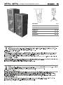 2
2
-
 3
3
-
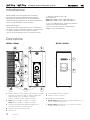 4
4
-
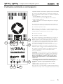 5
5
-
 6
6
-
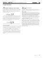 7
7
-
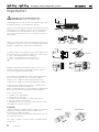 8
8
-
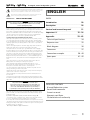 9
9
-
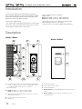 10
10
-
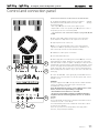 11
11
-
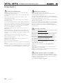 12
12
-
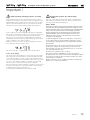 13
13
-
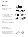 14
14
-
 15
15
-
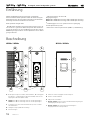 16
16
-
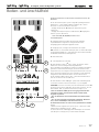 17
17
-
 18
18
-
 19
19
-
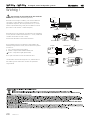 20
20
-
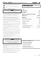 21
21
-
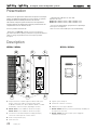 22
22
-
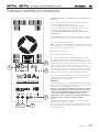 23
23
-
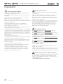 24
24
-
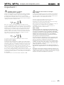 25
25
-
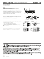 26
26
-
 27
27
-
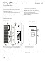 28
28
-
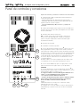 29
29
-
 30
30
-
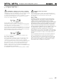 31
31
-
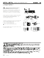 32
32
-
 33
33
-
 34
34
-
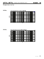 35
35
-
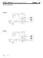 36
36
-
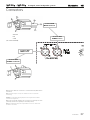 37
37
-
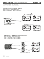 38
38
-
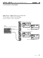 39
39
-
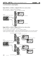 40
40
-
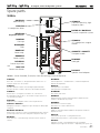 41
41
-
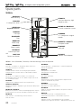 42
42
-
 43
43
-
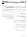 44
44
-
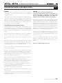 45
45
-
 46
46
-
 47
47
-
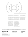 48
48


Montarbo W24 As Manual de usuario
- Tipo
- Manual de usuario
- Este manual también es adecuado para
en otros idiomas
- français: Montarbo W24 As Manuel utilisateur
- italiano: Montarbo W24 As Manuale utente
- English: Montarbo W24 As User manual
- Deutsch: Montarbo W24 As Benutzerhandbuch
- português: Montarbo W24 As Manual do usuário
Artículos relacionados
-
Montarbo W440A Manual de usuario
-
-
-
Montarbo NM250A Manual de usuario
-
-
-
-
-
-
Otros documentos
-
QSC Audio MD-FP122/124r Manual de usuario
-
dB Technologies ES503 Manual de usuario
-
 Master audio P-15SMA P-12CSW Manual de usuario
-
 Tributaries T200 Manual de usuario
-
 Pro DG Systems M 15 Manual de usuario
-
Vetus T12 Guía de instalación
-
Phonic iSK 15 Deluxe Manual de usuario
-


