
Multi Booster
BF16, BF24, BF32, BF40, BF48,
BF16T, BF24T, BF32T, BF40T, BF48T.

Content EN
1. Description .............................................................................................................3
1.1 Layout Multi Booster BF16 - BF24 ..................................................................4
1.2 Layout Multi Booster BF32 - BF40 - BF48 ......................................................5
1.3 Operation Diagrams Multi Booster BF16 - BF24 - BF32 - BF40 - BF48 .........6
2. Maintenance .........................................................................................................7
2.1 Filter ...............................................................................................................7
2.2 Long stops ......................................................................................................7
3. Start ...................................................................................................................... 7
3.1 New system ....................................................................................................7
4. Daily Operation .....................................................................................................7
4.1 Start ................................................................................................................7
4.2 Stop ................................................................................................................7
5. Service ..................................................................................................................8
5.1 Components ...................................................................................................8
5.1.1 Pump / Motor ......................................................................................8
5.1.2 Control system ...................................................................................8
5.1.3 Flow trigger ........................................................................................8
5.1.4 Non-return valve/intake side ..............................................................8
5.2 Recycling and scrapping .................................................................................8
6. Trouble Shooting ..................................................................................................9
6.1 The unit does not start ...................................................................................9
6.2 The "Δ"- lamp on the control panel is on ......................................................10
6.3 Too low or unstable pressure .......................................................................10
7. Recommended Spare Parts ...............................................................................11
.....................................................................................................11
9. Electric diagram ...................................................................................................12
10. Pump curve .........................................................................................................15
11. Declaration of Conformity ....................................................................................16

3
110002180
2
1
2
1. Description
The Booster in the Chameleon
Plus range is a completely functio-
ning pumping station that supplies
pressurised water to connected
satellite hygiene stations. There-
fore the Booster must be supplied
The station is then ready for hygi-
ene duties.
-
-
sures a constant working pressure
independent of usage pattern.
A typical Floor Booster installation
· Booster (1)
· Satellite (2)

4
15
11
14
2
7
4
8
6
12
5
3
9
10
13
24
1
16
10
110002115
110002183
17
22
18
20
23
21
19
1.7 Multi Booster BF16 - BF24
1. Water inlet
2. Manifold inlet
4. Pump
5. Manifold outlet
6. Outlet pipe
7. Inverter box
8. Filter box
9. Electrical connection box
10. Floor bracket
11. Inlet ball valve
12. Outlet ball valve
13. Operation panel
14. Strainer
15. Non Return Valve
16. Pressure sensor
17. Display
18. Navigation buttoms
19. Label
20. Name Label
21. • O Pushbutton.Stop
22. • I Pushbutton.Start
23. • Δ Lamp. Alight by error
24. Pressure sensor

5
110002116
110002183
17
22
18
20
23
21
19
14
11
2
4
8
7
3
12
5
6
9
10
13
24
1
15
16
26 10
25
1.3 Advanced Booster BF32 - BF40 - BF48
1. Water inlet
2. Manifold inlet
4. Pump
5. Manifold outlet
6. Outlet pipe
7. Inverter box
8. Filter box
9. Electrical connection box
10. Floor bracket
11. Inlet ball valve
12. Outlet ball valve
13. Operation panel
14. Strainer
15. Non Return Valve
16. Pressure sensor
17. Display
18. Navigation buttoms
19. Label
20. Name Label
21. • O Pushbutton.Stop
22. • I Pushbutton.Start
23. • Δ Lamp. Alight by error
24. Non return valve for by-pass
25. By-pass
26. Pressure sensor

6
W
D
FST1
SN8
B1
B2
PU 1
C1
F1
TE1 PE1
CP1
TE2 PE2
SN4
SN5
B1
B2
PU 2
C1
F1
TE1 PE1
CP1
TE2 PE2
SN4
SN5
B1
B2
PU x
C1
F1
TE1 PE1
CP1
TE2 PE2
SN4
SN5
110002307
1.3 Operating Diagrams acc. ISO14617
Multi Booster BF16 - BF24 - BF32 - BF40 - BF48
B. Ball valve.
F. Filter
FST. Flow switch.
C. Check valve.
PE. Pressure sensor.
TE. Temperature sensor.
CP. Centrifugal pump.
D. Outlet.
PU. Pump unit.
W. Water inlet.
SN : Socket no.

7
Fig. 1 0627106
Fig. 4 110002183
Fig. 3 0627131
A
Fig. 2 110002117
2. Maintenance
The Booster unit is maintenance
free. However, we recommend
cleaning the booster unit in connec-
tion with the occasional cleaning
-
venient intervals (approx. every 1-3
months) depending of the amount
of impurities in the water.
2.1 Filter
1. Press “0” on the control panel
to stop the Booster.
2. Interrupt the master switch
(Fig. 1).
3. Close the water inlet .
4. Open a tap to release the
system of pressure.
and place it in a descaling
solution.
Note: MB systems are not
delivered with a factory mount-
2.2 Before a longer
production stop
If long production stops are
planned (more than 6 months) and
the pump is drained, it is recom-
mended that the pump is secured
as follows:
1. Remove the coupling safety
guard.
2. Spray a couple of drops of sili-
cone oil onto the axle between
the top section and the cou-
pling.
Carefully follow the instructions
given in the manual provided by
the pump supplier.
3. Start
3.1 New system
In order to ensure a problem-free
start up of a new system the pipe
Bleeding the pipe system
1. Turn on the water supply to
rinse and bleed the entire sys-
tem. If satellites are installed
open the tap furthest away
until no air or dirt comes out.
Then rinse and bleed the next
tap and continue until the tap
closest to you has been rinsed
and bled.
2. Mount satellites, if any
Bleeding the pump
3. Press “0” on the control panel
to stop the Booster.
4. Loosen the relief plug (A,
Fig34) 1-2 revolutions until
Note. Never loosen the relief
plug while the pump is running
as this may damage the pack-
ing and cause personal injury.
5. Tighten the relief plug again
6. Start the pump so that all re-
maining air pockets are forced
up to the top of the pump.
7. Stop the pump.
8. Loosen the relief plug 1-2
revolutions again and bleed
the system until only water
9. Tighten the relief plug once
more.
The Booster is now ready for
operation. Press “I” on the control
4. Daily operation
4.1 Start
1. Check that water supplies for
the system are open.
2. Press “I” on the control board
in order to start up the unit.
4.2 Stop
1. Press “0” on the control panel
to stop.
Note. Due to the following it is very
water and air supply after use:
• If the air supply is open when
the main station or satellites are
not in use, air might leak into
the water line. If this happens,
the system must be bled once
more.
• The water separator, which is a
part of the air regulator, is only
to be emptied when the air sup-
ply is closed.
After a long time production stop
(holidays etc) it might be necessary
to bleed the piping system and the
booster unit again.
mounted in a MB system, the
descaling procedure is exactly
the same until the scale is dis-
solved.
-
oughly and remount.
800µ ->

8
5. Service
Service may only be carried out by
Warning: The system must only be
serviced when there is no voltage
or pressure on the system.
control box (Fig. 1)
2. Open a water outlet to depres-
surise the system.
5.1 Components
5.1.1 Pump / motor
Pump/motor are maintenance free,
see section 2.2
5.1.2 Control system
Maintenance free
If defective: Call service technician
5.1.3 Flow Switch
Maintenance-free.
has to be done in such way that
the plug/cable end of the switch is
5.1.3.1 Adjustment of ow switch
installed it has to be adjusted.
1. Press "1" on the control panel
to turn on the machine.
2. Turn "rinse/foam" handle on a
satellite to foam position.
3. Activate the spray handle on
the outlet hose of the satellite
so water runs out.
4.
turned the correct way (the
direction) (see picture).
5. Remove the white plug/screw
before adjusting (see picture).
6.
diode lights up (see picture).
7. Close the spray handle again
and check that the red diode
lights up.
8. Remount the white plug/screw.
5.1.4 Non-return valve / inlet side
Maintenance - free.
If defective, replace the non-return
valve.
5.2 Recycling/scrapping
Recycle the wrapping and scrap
the machine according to recom-
mendations from the local authori-
ties.
Remove
white plug Adjust settings
One green
diode
The red
diode
Plug/Cable
Flow direction
Flow switch
110004660
110004714

9
6. Troubleshooting
6.1 The unit does not start
Is there voltage
to the unit? Reconnect voltageNo
Is the ’Δ’ lamp
flashing?
Yes
Go to section 6.2Yes
No
Go to setup→settings
menu → Startup
method, and set it to
pressure
Does the unit start
Call a service
technician
Yes
No
Set unit back to
Flow start in setup
menu
Try to readjust
flow switch
(chapter 5.1.3.1)
Can the unit start?No
OK
Yes

10
6.2 The "Δ"- lamp on the control panel is on
6.3 If the inlet pressure is low or unstable
Check the display
for error
messages
Press ”0" wait for a few
seconds and then
press ”I” on the control
panel to restart the
system.
Does the error
come back
Go to
softwaremanual
Start using the unit
again
Yes
No
Check the inlet
pressure is
between 2-8bar, at
maximum water
consumption
Is the pump leaking
or making jarring
sounds?
Call a service
technician
Is there sufficient
water supply?
Yes
Is the filter
Clogged Clean the filter
Yes/no
No Yes
Secure higher inlet
pressure
No

11
7. Recommended spare parts
Technical Data Multi Booster.
BF16 BF24 BF32 BF40 BF48
Max. Outlet pressure. bar 25* 25* 25* 25* 25*
Consumption during rinsing. L/min 440 660 880 1100 1320
Consumption during foaming. L/min 160 240 320 400 480
Min. supply pressure. bar 2 2 2 2 2
Max. supply pressure. bar 8 8 8 8 8
Min. water supply. L/min 500 750 1000 1250 1500
Max. water temp. °C 70 70 70 70 70
Pipe dimension inlet Ø inch 2 1/2" 3" 4" 4" 4"
Pipe dimension outlet Ø inch 2 1/2" 3" 4" 4" 4"
Electricity
Supply voltage V 3/PE 400 V ±10%
50±2
Motor load (kW) kW 22 33 44 55 66
Installation to EN 60204-1
Nominal current A 55 82,5 110 137,5 165
Fuse A 63 100 125 160 200
L1, L2, L3, PE mm2 2.5 2.5 2,5 6 6
General
Sound level ISO 11202 dB 85 dB - - - -
Dimensions mm 1112x530x1043 1112x530x1477 1268x665x2399 1268 x 665 x 2822 1268 x 665 x 3248
Weight (kg) ca kg 190 300 400 500 600
Note:
* Pump pressure 20 bar + inlet pressure max. 25 bar
8. Specications
The recommended spare parts are marked with * in the spare part manual.

12
5
5
4
4
3
3
2
2
1
1
D D
C C
B B
A A
3/PE
400V/ 27A (Nom)
Max current 28A
Rubber cable
4 x 6,0mm2
Brown
1.5mm2
40cm
Black
1.5mm2
40cm
Shield cable
4 x 6,0mm2
120cm
Shield cable
4 x 4,0mm2
85cm
From Main box
Only one displayPump unit
Black 6,0mm2, 40cm
Grey 6,0mm2, 40cm
Brown 6,0mm2, 40cm
Grey
Brown
Yellow/green
Black
To Con 10 at next pump unit or tank control
No:
Desc:
Version/Revision
Product no:
Drawn by:
Initials: Date:
Sheet size:
Sheet no: of
A4
11
san 21Nov11
A
110002302
Electrical connections MB
Blytaekkervej 2
DK-9000 Aalborg
+45 72 18 20 00
www.nilfiskfood.com
No:
Desc:
Version/Revision
Product no:
Drawn by:
Initials: Date:
Sheet size:
Sheet no: of
A4
11
san 21Nov11
A
110002302
Electrical connections MB
Blytaekkervej 2
DK-9000 Aalborg
+45 72 18 20 00
www.nilfiskfood.com
No:
Desc:
Version/Revision
Product no:
Drawn by:
Initials: Date:
Sheet size:
Sheet no: of
A4
11
san 21Nov11
A
110002302
Electrical connections MB
Blytaekkervej 2
DK-9000 Aalborg
+45 72 18 20 00
www.nilfiskfood.com
L
I
N
E
L
O
A
D
EMC filter 30A
L1
L2
L3
L1
L2
L3
M
3
Motor 11kW
U1
V1
W1
Main Switch
1L1
3L2
5L3
2T1
4T2
6T3
1
2
3
Yellow/green
1
2
3
Yellow/green
ShieldShield
Controller PCB
AC1
AC2
JP12
CON10
CON11
Frequency inverter 11kW
L1
L2
L3
B-
B+
U
V
W
Display
Black
Grey
Brown
Yellow/green
Black
Grey
Brown
Yellow/green
1
2
3
Yellow/green
1
2
3
Yellow/green
Shield Shield
9. Electric diagram9. Electric diagram

13
5
5
4
4
3
3
2
2
1
1
D D
C C
B B
A A
To pump unit 1 To pump unit 2 To pump unit x
Yellow/green
Brown
Grey
Balck
Yellow/green
Brown
Grey
Balck
Yellow/green
Brown
Grey
Balck
No:
Desc:
Version/Revision
Product no:
Drawn by:
Initials: Date:
Sheet size:
Sheet no: of
A4
11
san 22Nov11
A
110002310
Main Box connections
Blytaekkervej 2
DK-9000 Aalborg
+45 72 18 20 00
www.nilfiskfood.com
No:
Desc:
Version/Revision
Product no:
Drawn by:
Initials: Date:
Sheet size:
Sheet no: of
A4
11
san 22Nov11
A
110002310
Main Box connections
Blytaekkervej 2
DK-9000 Aalborg
+45 72 18 20 00
www.nilfiskfood.com
No:
Desc:
Version/Revision
Product no:
Drawn by:
Initials: Date:
Sheet size:
Sheet no: of
A4
11
san 22Nov11
A
110002310
Main Box connections
Blytaekkervej 2
DK-9000 Aalborg
+45 72 18 20 00
www.nilfiskfood.com
Main Switch
Black
Grey
Brown
Yellow/green
Black
Grey
Brown
Yellow/green
F2
32A
Black
Grey
Brown
Yellow/green
Black
Grey
Brown
Yellow/green
Black
Grey
Brown
Yellow/green
Black
Grey
Brown
Yellow/green
Fx
32A
F1
32A

14
5
5
4
4
3
3
2
2
1
1
D D
C C
B B
A A
TANK
Last pump in unit
Control board plug 11
Max. load for signals 100mA
U
V
W
Pump start signal
Valve Open/close signal
Alarm Signal
+24VDC
No:
Desc:
Version/Revision
Product no:
Drawn by:
Initials: Date:
Sheet size:
Sheet no: of
A4
11
san 21Nov11
A
110002309
Tank Control
Blytaekkervej 2
DK-9000 Aalborg
+45 72 18 20 00
www.nilfiskfood.com
No:
Desc:
Version/Revision
Product no:
Drawn by:
Initials: Date:
Sheet size:
Sheet no: of
A4
11
san 21Nov11
A
110002309
Tank Control
Blytaekkervej 2
DK-9000 Aalborg
+45 72 18 20 00
www.nilfiskfood.com
No:
Desc:
Version/Revision
Product no:
Drawn by:
Initials: Date:
Sheet size:
Sheet no: of
A4
11
san 21Nov11
A
110002309
Tank Control
Blytaekkervej 2
DK-9000 Aalborg
+45 72 18 20 00
www.nilfiskfood.com
T1
400V/230V
HL
HLA
10
OUT1
OUT2
5
.
.
1
INP1 INP2 INP3 INP4
OUT3
U1
TankControl
F1
10A
LL
T2
230Vac/24VDC supply
L
N
+
-LLA
F2
Fuse

15
0
5
10
15
20
25
30
0 100 200 300 400 500 600 700 800 900 1000 1100 1200 1300 1400 1500
Pressure [bar]
Flow [l/min]
Pumpcurve BF16-BF48
BF16 (22kW) @ 4 bar supply
BF24 (33kW) @ 4 bar supply
BF32 (44kW) @ 4 bar supply
BF40 (55kW) @ 4 bar supply
BF48 (66kW) @ 4 bar supply
110000455
10. Pump curve

16
BF16, BF24, BF32, BF40, BF48
Declaration of Conformity
Konformitätserklärung
Déclaration de Conformité
Dichiarazione di Conformità
Declaración de Conformidad
Declaração de Conformidade
Δήλωση Συμμόρφωσης
Overeenkomstigheidsverklaring
Försäkran om överensstämmelse
Vaatimustenmukaisuusvakuutus
Overensstemmelseserklæring
Deklaracja zgodności
Декларация о соответствии
Megfelelőségi nyilatkozat
Izjava o skladnosti
Izjava o usklađenosti
Deklaracija o konformitetu
Declaraţie de Conformitate
11. Declaration of Conformity

17
Nilsk FOOD
Blytækkervej 2
9000 Aalborg
Danmark
Declaration of Conformity
BF16+, BF24+, BF32+, BF40+, BF48+, to which this declaration relates,
are in conformity with these Council directives on the approximation of
the laws of the EC menber states:
Function: Pumping Station
Model/Type: BF16-2+, BF24-3+, BF32-4+, BF40-5+, BF48-6+.
Serial number: All
Machinery Directive (2006/42/EC:2006-05-17).
Standard used: EN 60335-2-41/A2:2010
EMC Directive (2004/108/EC:2004-12-15).
Standard used: EN 55014-1/A1:2009 and EN 55014-2/A2:2008
Standard used: EN 61000-3-2/A2:2009 and EN 61000-3-3:2008
Konformitätserklärung
BF16+, BF24+, BF32+, BF40+, BF48+, in Übereinstimmung
Mitgliedstaaten ist:
Funktion: Pumpenstation
Modell/Typ: BF16-2+, BF24-3+, BF32-4+, BF40-5+, BF48-6+.
Seriennummer: Alle
Maschinendirektive (2006/42/EC:2006-05-17).
Standarden: EN 60335-2-41/A2:2010
EMC Direktive (2004/108/EC:2004-12-15).
Standarden: EN 55014-1/A1:2009 og EN 55014-2/A2:2008
Standarden: EN 61000-3-2/A2:2009 og EN 61000-3-3:2008
Déclaration de conformité
les produits BF16+, BF24+, BF32+, BF40+, BF48+,
Fonction : Station de pompage
BF16-2+, BF24-3+, BF32-4+, BF40-5+, BF48-6+.
Directive 2006/42/CE du 17 mai 2006 relative aux machines
Directive CEM (2004/108/CE:2004-12-15).
Dichiarazione di conformità
Modello/Tipo: BF16-2+, BF24-3+, BF32-4+, BF40-5+, BF48-6+.
Numero di serie: Tutti
Direttiva Macchine (2006/42/CE:2006-05-17).
Direttiva EMC (2004/108/CE:15.12.04).

18
Declaración de Conformidad
BF16+, BF24+, BF32+, BF40+,
BF48+,
miembros de la CE:
Modelo/tipo: BF16-2+, BF24-3+, BF32-4+, BF40-5+, BF48-6+.
All
Normativa usada: EN 60335-2-41/A2:2010
Directiva CEM (2004/108/EC:15.12.04).
Normativa usada: EN 55014-1/A1:2009 y EN 55014-2/A2:2008
Normativa usada: EN 61000-3-2/A2:2009 y EN 61000-3-3:2008
Declaração de Conformidade
produtos BF16+, BF24+, BF32+, BF40+, BF48+, referidos nesta
declaração, se encontram em conformidade com estas diretivas do
Estados-Membros da CE:
Função: Estação de bombagem
Modelo/Tipo: BF16-2+, BF24-3+, BF32-4+, BF40-5+, BF48-6+.
Diretiva CEM (2004/108/CE:2004-12-15).
Δήλωση Συμμόρφωσης
BF16+, BF24+, BF32+, BF40+, BF48+,
BF16-2+, BF24-3+, BF32-4+, BF40-5+, BF48-6+.
:
A2:2008
3-3:2008
Overeenkomstigheidsverklaring
dat de producten BF16+, BF24+, BF32+, BF40+, BF48+,
wetgevingen van de EG-lidstaten:
Functie: Pompinstallatie
Model/Type: BF16-2+, BF24-3+, BF32-4+, BF40-5+, BF48-6+.
Serienummer: Alle
Machinerichtlijn (2006/42/EG:17-05-2006).
Toegepaste norm: EN 60335-2-41/A2:2010
EMC-richtlijn (2004/108/EG:15-12-2004).
Toegepaste norm: EN 55014-1/A1:2009 en EN 55014-2/A2:2008
Toegepaste norm: EN 61000-3-2/A2:2009 en EN 61000-3-3:2008
Försäkran om överensstämmelse
BF16+, BF24+, BF32+, BF40+, BF48+, som omfattas av denna
Funktion: Pumpstation
Modell/typ: BF16-2+, BF24-3+, BF32-4+, BF40-5+, BF48-6+.
Serienummer: Alla
Maskindirektiv (2006/42/EC:2006-05-17).
EMC-direktivet (2004/108/EG :2004-12-15).
A2:2008
3:2008
Vaatimustenmukaisuusvakuutus
yhdenmukaisuutta koskien seuraavia:
Toiminto: Pumppuasema
Malli/tyyppi: BF16-2+, BF24-3+, BF32-4+, BF40-5+, BF48-6+.
Sarjanumero: Kaikki
Konedirektiivi (2006/42/EY:2006-05-17).
EMC-direktiivi (2004/108/EY:2004-12-15).

19
Overensstemmelseserklæring
medlemslandenes love:
Function: Pumping Station
Model/Type: BF16-2+, BF24-3+, BF32-4+, BF40-5+, BF48-6+.
Serial number: All
Machinery Directive (2006/42/EC:2006-05-17).
Standard used: EN 60335-2-41/A2:2010
EMC Directive (2004/108/EC:2004-12-15).
Standard used: EN 55014-1/A1:2009 and EN 55014-2/A2:2008
Standard used: EN 61000-3-2/A2:2009 and EN 61000-3-3:2008
Deklaracja zgodności
BF16+, BF24+, BF32+, BF40+, BF48+,
Model/typ BF16-2+, BF24-3+, BF32-4+, BF40-5+, BF48-6+.
Stosowana norma: EN 60335-2-41/A2:2010
(2004/108/EC:15.12.04).
Stosowane normy: EN 55014-1/A1:2009 i EN 55014-2/A2:2008
Stosowane normy: EN 61000-3-2/A2:2009 i EN 61000-3-3:2008
Декларация о соответствии
BF16+, BF24+,
BF32+, BF40+, BF48+,
BF16-2+, BF24-3+, BF32-4+, BF40-5+, BF48-6+.
:
A2:2008
3:2008
Megfelelőségi nyilatkozat
EMC irányelv (2004/108/EC:2004-12-15).
Izjava o skladnosti
Funkcija:
Model/Tip: BF16-2+, BF24-3+, BF32-4+, BF40-5+, BF48-6+.
Direktiva o strojih (2006/42/EC:2006-05-17).
Uporabljeni standardi: EN 60335-2-41/A2:2010
(2004/108/
EC:2004-12-15).
Uporabljeni standardi: EN 55014-1/A1:2009 and EN 55014-2/
A2:2008
Uporabljeni standardi: EN 61000-3-2/A2:2009 and EN 61000-3-
3:2008
Izjava o usklađenosti
EU:
Funkcija: Pumpna postaja
Model/vrsta: BF16-2+, BF24-3+, BF32-4+, BF40-5+, BF48-6+.
Serijski broj: Svi
Primijenjena norma: EN 60335-2-41/A2:2010
12-15).
Primijenjena norma: EN 55014-1/A1:2009 i EN 55014-2/A2:2008
Primijenjena norma: EN 61000-3-2/A2:2009 i EN 61000-3-3: 2008

20
Deklaracija o konformitetu
Funkcija:
Model/tip: BF16-2+, BF24-3+, BF32-4+, BF40-5+, BF48-6+.
serijski broj: Kompletna
Primenjen standard: EN 60335-2-41/A2:2010
EMC direktiva (2004/108/EC:2004-12-15).
Primenjen standard: EN 55014-1/A1:2009 i EN 55014-2/A2:2008
Primenjen standard: EN 61000-3-2/A2:2009 i EN 61000-3-3:2008
Declaraţie de Conformitate
Statelor Membre CE:
Model/Tip: BF16-2+, BF24-3+, BF32-4+, BF40-5+, BF48-6+.
toate
EN 60335-2-41/A2:2010
Directiva EMC (2004/108/EC:15.12.04).
Декларация за съответствие
: BF16-2+, BF24-3+, BF32-4+, BF40-5+, BF48-6+.
EN 60335-2-41/A2:2010
Prohlášení o shodě
oblastech:
Funkce:
Model/Typ: BF16-2+, BF24-3+, BF32-4+, BF40-5+, BF48-6+.
EN 60335-2-41/A2:2010
EN 55014-1/A1:2009 a EN 55014-2/A2:2008
EN 61000-3-2/A2:2009 a EN 61000-3-3:2008
Prehlásenie o konformite
Funkcia:
Model/typ: BF16-2+, BF24-3+, BF32-4+, BF40-5+, BF48-6+.
EN 60335-2-41/A2: 2010
Smernica o elektromagnetickej kompatibilite (2004/108/
ES: 15.12.2004).
EN 55014-1/A1: 2009 a EN 55014-2/A2: 2008
EN 61000-3-2/A2: 2009 a EN 61000-3-3: 2008
Uygunluk Bildirgesi
BF16+, BF24+, BF32+,
BF40+, BF48+,

21
Vastavusdeklaratsioon
Funktsioon: Pumbajaam
Seerianumber:
Masinadirektiiv (2006/42/EÜ:2006-05-17).
Kasutatav standard: EN 60335-2-41/A2:2010
EÜ:2004-12-15).
Kasutatav standard: EN 55014-1/A1:2009 ja EN 55014-2/A2:2008
Kasutatav standard: EN 61000-3-2/A2:2009 ja EN 61000-3-3:2008
Atitikties deklaracija
Paskirtis: Pumpavimo terminalas
Modelis / tipas: BF16-2+, BF24-3+, BF32-4+, BF40-5+, BF48-6+.
Serijos numeris: visi
taikytas standartas: EN 60335-2-41/A2:2010;
EB:2004-12-15),
taikytas standartas: EN 55014-1/A1:2009 ir EN 55014-2/A2:2008,
taikytas standartas: EN 61000-3-2/A2:2009 ir EN 61000-3-3:2008
Paziņojums par atbilstību prasībām
Funkcija:
Modelis/tips: BF16-2+, BF24-3+, BF32-4+, BF40-5+, BF48-6+.
visi.
EN 60335-2-41/A2:2010
EK, 15.12.2004.)
A2:2008
3:2008
Свідчення про відповідність вимогам
, BF16+, BF24+, BF32+, BF40+, BF48+,
,
- :
BF16-2+, BF24-3+, BF32-4+, BF40-5+, BF48-6+.
EN 60335-2-41/A2:2010
EC:2004-12-15).
Technical le responsible:
Flemming Asp
Blytaekkervej 2
9000 Aalborg, Denmark

Inhalt DE
1. Beschreibung .......................................................................................................23
1.1 Layout Multi Booster BF16 - BF24 ................................................................24
1.2 Layout Multi Booster BF32 - BF40 - BF48 ....................................................25
1.3 Funktionsdiagramme Multi Booster BF16 - BF24 - BF32 - BF40 - BF48 ......26
2. Wartung ...............................................................................................................27
2.1 Filter ..............................................................................................................27
.............................................................................................27
3. Start .....................................................................................................................27
3.1 Eine neue Anlage ..........................................................................................27
2
4. Tagliche Inbetriebnahme .....................................................................................27
4.1 Starten ...........................................................................................................27
4.2 Stoppen .........................................................................................................27
5. Service / inspektion .............................................................................................28
5.1 Komponenten ................................................................................................28
5.1.1 Pumpe / Motor ..................................................................................28
5.1.2 Kontrolsystem ..................................................................................28
5.1.3 Flowtrigger .......................................................................................28
5.1.4 ......................................................28
5.2 Recycling und Entsorgung ............................................................................28
6. Fehlersuche .........................................................................................................29
6.1 Die Anlage will nicht starten ..........................................................................29
6.2 "Δ"- Lampe an dem Kontroll-Paneel leuchtet ................................................30
.....................................................................30
...............................................................................31
....................................................................................................31
9. Schaltplan ............................................................................................................32
10. Pumpenkurve ......................................................................................................35
.........................................................................................36

23
110002180
2
1
2
1. Beschreibung
arbeitende Pumpstation, die unter
-
bundene Satellitenhygienesta-
-
kationen, muss die Booster immer
Stromversorgung versorgt werden.
-
eneaufgaben bereit.
-
-
muster, einen konstant arbeiten-
den Druck sichert.
Wichtig:
3
-
· Booster (1)
· Satellit (2)

24
15
11
14
2
7
4
8
6
12
5
3
9
10
13
24
1
16
10
110002115
110002183
17
22
18
20
23
21
19
1.1 Multi Booster BF16 - BF24.
1. Wassereinlassrohr
2. Verteilerrohreingang
4. Pumpe
5. Verteilerrohrausgang
6. Ausgangsrohr
7. Inverterkasten
8. Filterkasten
9. Elektrischer anschluss-kasten
11. Eingang Kugelhahn
13. Schalttafel
14. Filter
18. Navigationsknöpfe
19. Aufkleber
20. Namensaufkleber
21. • O Druckknopf. Stopp
22. • I Druckknopf.Start
23. • Δ Lampe. Leuchtet im fall eines Fehlers
24

25
110002116
110002183
17
22
18
20
23
21
19
14
11
2
4
8
7
3
12
5
6
9
10
13
24
1
15
16
26 10
25
1.2 Multi Booster BF32 - BF40 - BF48.
1. Wassereinlassrohr
2. Verteilerrohreingang
4. Pumpe
5. Verteilerrohrausgang
6. Ausgangsrohr
7. Inverterkasten
8. Filterkasten
9. Elektrischer anschluss-kasten
11. Eingang Kugelhahn
13. Schalttafel
14. Filter
18. Navigationsknöpfe
19. Aufkleber
20. Namensaufkleber
21. • O Druckknopf. Stopp
22. • I Druckknopf.Start
23. • Δ Lampe. Leuchtet im fall eines Fehlers
24.
25. By-pass
26

26
W
D
FST1
SN8
B1
B2
PU 1
C1
F1
TE1 PE1
CP1
TE2 PE2
SN4
SN5
B1
B2
PU 2
C1
F1
TE1 PE1
CP1
TE2 PE2
SN4
SN5
B1
B2
PU x
C1
F1
TE1 PE1
CP1
TE2 PE2
SN4
SN5
110002307
1.3 Funktionsdiagramme gemäß ISO14617
Multi Booster BF16 - BF24 - BF32 - BF40 - BF48
B. Kugelventil.
F. Filter
PE. Drucksensor.
TE. Temperatursensor.
D. Ausgang.
PU. Pump-Einheit.
W. Wassereinlassrohr.

27
Fig. 1 0627106
Fig. 4 110002183
Fig. 3 0627131
A
Fig. 2 110002117
2.2 Bevor einen längeren
Produktionstopp
-
wo die Pumpe von Wasser geleert
abmontieren.
2. Ein paar Tropfen Silikonöl in
-
derkopf und der Kuppelung
beiliegende Bedienungsanleitung
des Pumpenlieferanten genau-
3. Start
NB! Die Pumpe muss vor dem
3.1 Eine neue Anlage
Um einen problemfreien Start einer
-
Auslüftung des Rohrsystems
1. Die “0” auf der Schalttafel
-
-
-
liert, wird der am entfernteste
Unreinheiten und Luft mehr
austreten. Daraufhin wird der
und so weiter und so fort, bis
ist..
2. Wartung
Die Booster Anlage ist wartungsfrei.
Wir empfehlen aber, in Verbindung
mit der allgemeinen Reinigung im
reinigen. Das Filter mit passenden
von Unreinigkeiten im Wasser.
2.1 Filter
1. Die “0” auf der Schalttafel
2. Den Hauptschalter aus-
schalten (Fig. 1).
3. Den Wassereinlass unterbre-
chen.
5. Entfernen Sie den Filter (A,
Abb. 2), und legen Sie den Filter
in einer Entkalkunslösung.
Hinweis: MB-Systeme werden
nicht von der Fabrik mit einem
Filter geliefert. Im Falle einen
Filter in einem MB-System
montiert ist, ist das Entka-
lkungsverfahren wie oben
beschrieben.
6. Den gereinigten Filter
-
um anmontieren.
3. Eventuelle Satelliten werden
nun montiert.
Auslüftung der Pumpe(n)
-
hungen lockern (A, Fig.3), bis
Wasser und Luft herauskom-
men.
NB!
Pumpenbetrieb nie lösen als dies
-
sachen.
6. Die Pumpe starten, um die
7. Die Pumpe stoppen.
Umdrehungen lockern und
austritt.
-
triebnahme bereit.
“I“-
en (siehe Fig.4)
4. Tägliche
Inbetriebnahme
4.1 Starten
1. Sicherstellen, dass der
2. “I” auf dem Bedienung-
4.2 Stoppen
1. “0”-
2. Den Wassereingang

28
BERMERKEN. Aus folgenden
Sie die Wasser- und Luftver-
sorgung immer nach Gebrauch
abschalten.
•
ist, wenn die Hauptstation und
die Satelliten nicht in Gebrauch
sind, kann Luft in Wasserleitung
sickern. Dann muss das System
• Der Wasserabscheider, der
einen Teil des Luftreglers ist, nur
leeren, wenn die Luftversorgung
abgeschlossen ist.
-
tionsstopp (Urlaub usw.)
kann es notwendig sein, das
Rohrsystem und die Booster
5. Service / Inspektion
Die Inspektion darf nur von autorisi-
werden.
Warnung! Die Inspektion am
System darf erst vorgenommen
werden, wenn das System von
spannungs- und druckfrei ist.
1. Den Hauptschalter an der
Kontrollbox abschalten (Fig.1)
-
gang, um die Anlage druckfrei
5.1 Komponenten
5.1.1 Pumpe / Motor
Pumpe und Motor sind beide war-
tungsfrei (siehe Abschnitt 2.2).
5.1.2 Kontrollsystem
Das kontrollsystem ist ebenfalls
wartungsfrei. Im Fall eines Defekts,
einen Servicetechniker kontak-
tieren.
5.1.3 Flow Switch
Der Auslössensor (Switch) ist
ebenfalls wartungsfrei. Im Fall
eines Defekts, wird der Auslössen-
sor (Switch) ausgewechselt.
Die Ausrichtung des Strömungss-
chalters muss so erfolgen, dass der
Stecker/das Kabel des Schalters
weist.
Plug/Cable
Flow direction
Flow switch
5.1.3.1 Ausrichtung des
Strömungsschalters
Wenn der Strömungsschalter aus-
getauscht/installiert wird, muss er
ausgerichtet werden.
1.
"1", um die Maschine ein-
2.
Schaum" an einem Satel-
-
lung.
3. -
Wasser austritt.
4. -
mungsschalter auf die kor-
rekte Weise gedreht wird (der
Draht muss der Flussrichtung
-
dung).
5.
Stecker/die Schraube vor der
Ausrichtung (siehe Abbildung).
6. Richten Sie die Flussrichtung
-
7.
8.
Stecker/die Schraube wieder.
ausgerichtet.
Remove
white plug Adjust settings
One green
diode
The red
diode
5.1.4 Rückschlagventil /
Zugangsseite
Im Fall eines Defekts, wird das
Contraventil ausgewechselt.
5.2 Recycling und Ent-
sorgung
Verpackungsmaterial recyceln
den jeweils geltenden Vorschriften
entsorgen.
110004660
110004714

29
6. Fehlersuche
6.1 Die Anlage will nicht starten
Liegt am Gerät
Spannung an?
Spannungsversor
gung wieder
herstellen.
Nein
Blinkt dieΔ’-
Lampe?
Ja
Weiter mit
Abschnitt 6.2.
Ja
Nein
Unter Setup→Einstell-
menü → Startverfahren
die Option Druck
auswählen.
Startet das Gerät?
Servicetechniker
benachrichtigen.
Ja
Nein
Gerät im
Einstellmenü
zurücksetzen auf
Start Durchlauf.
Durchflussschalter
neu einstellen
(Kapitel 5.1.3.1).
Startet das Gerät?Nein
o. k.
Ja

30
6.2 "Δ"- Lampe an dem Kontroll-Paneel leuchtet
6.3 Falls der Einlassdruck zu niedrig oder unstabil ist.
Display auf
Fehlermeldungen
Systems am
einige Sekunden
Wird der Fehler
Siehe
Softwarehandbuch.
Betrieb nehmen.
Ja
Nein
Eingangsdruck bei
maximalem
Wasserverbrauch
Ist die Pumpe undicht oder
von sich?
Servicetechniker
benachrichtigen.
Ist die
ausreichend?
Ja
Ist der Filter
verstopft? Filter reinigen.
Ja/Nein
Nein Ja
Höheren
Eingangsdruck
sicherstellen.
Nein

31
7. Empfehlenswerte Ersatzteile
Die empfohlene Ersatzteile sind im Ersatzteilmanual mit * markiert.
8. Spezikationen
Technische Daten Booster/Main station.
Advanced* Pro.*
Wasser Unit. 3 (4 kW) 3 (4 kW) 4 (5.5 kW) 7 (10 kW)** 8 (11 kW)*
Max. Ausgangsdruck. bar 25 25 25 22 25
L/min 90 90 120 210 240
Verbrauch bei Schaumbetrieb. L/min 30 30 40 80 80
bar 2 2 2 2 2
bar 8 8 8 8 8
L/min 100 100 135 265 265
Max. Wassertemperatur. °C 70 70 70 70 70
inch 1.1/4" 1.1/4" 1.1/4" 2" 2"
inch 1.1/4" 1.1/4" 1.1/4" 2" 2"
Elektrizität
V3/PE 400 V±10%
Bewegungslast (kW) kW 4 4 5.5 10 10
Nominaler Strom A 10.6 10,6 14.2 27 27
Sicherung A 16 16 20 35 35
L1, L2, L3, PE mm2 2.5 2.5 2.5 6 6
Generell
dB 85 dB - - - -
mm 1070 x 550 x 375 785 x 550 x 375 1074 x 557 x 382 1074 x 557 x 382 990 x 535 x 364
Gewicht (kg) kg 85 60 75 75 80
Bemerkung:

32
5
5
4
4
3
3
2
2
1
1
D D
C C
B B
A A
3/PE
400V/ 27A (Nom)
Max current 28A
Rubber cable
4 x 6,0mm2
Brown
1.5mm2
40cm
Black
1.5mm2
40cm
Shield cable
4 x 6,0mm2
120cm
Shield cable
4 x 4,0mm2
85cm
From Main box
Only one displayPump unit
Black 6,0mm2, 40cm
Grey 6,0mm2, 40cm
Brown 6,0mm2, 40cm
Grey
Brown
Yellow/green
Black
To Con 10 at next pump unit or tank control
No:
Desc:
Version/Revision
Product no:
Drawn by:
Initials: Date:
Sheet size:
Sheet no: of
A4
11
san 21Nov11
A
110002302
Electrical connections MB
Blytaekkervej 2
DK-9000 Aalborg
+45 72 18 20 00
www.nilfiskfood.com
No:
Desc:
Version/Revision
Product no:
Drawn by:
Initials: Date:
Sheet size:
Sheet no: of
A4
11
san 21Nov11
A
110002302
Electrical connections MB
Blytaekkervej 2
DK-9000 Aalborg
+45 72 18 20 00
www.nilfiskfood.com
No:
Desc:
Version/Revision
Product no:
Drawn by:
Initials: Date:
Sheet size:
Sheet no: of
A4
11
san 21Nov11
A
110002302
Electrical connections MB
Blytaekkervej 2
DK-9000 Aalborg
+45 72 18 20 00
www.nilfiskfood.com
L
I
N
E
L
O
A
D
EMC filter 30A
L1
L2
L3
L1
L2
L3
M
3
Motor 11kW
U1
V1
W1
Main Switch
1L1
3L2
5L3
2T1
4T2
6T3
1
2
3
Yellow/green
1
2
3
Yellow/green
ShieldShield
Controller PCB
AC1
AC2
JP12
CON10
CON11
Frequency inverter 11kW
L1
L2
L3
B-
B+
U
V
W
Display
Black
Grey
Brown
Yellow/green
Black
Grey
Brown
Yellow/green
1
2
3
Yellow/green
1
2
3
Yellow/green
Shield Shield
9. Schaltplan

33
5
5
4
4
3
3
2
2
1
1
D D
C C
B B
A A
To pump unit 1 To pump unit 2 To pump unit x
Yellow/green
Brown
Grey
Balck
Yellow/green
Brown
Grey
Balck
Yellow/green
Brown
Grey
Balck
No:
Desc:
Version/Revision
Product no:
Drawn by:
Initials: Date:
Sheet size:
Sheet no: of
A4
11
san 22Nov11
A
110002310
Main Box connections
Blytaekkervej 2
DK-9000 Aalborg
+45 72 18 20 00
www.nilfiskfood.com
No:
Desc:
Version/Revision
Product no:
Drawn by:
Initials: Date:
Sheet size:
Sheet no: of
A4
11
san 22Nov11
A
110002310
Main Box connections
Blytaekkervej 2
DK-9000 Aalborg
+45 72 18 20 00
www.nilfiskfood.com
No:
Desc:
Version/Revision
Product no:
Drawn by:
Initials: Date:
Sheet size:
Sheet no: of
A4
11
san 22Nov11
A
110002310
Main Box connections
Blytaekkervej 2
DK-9000 Aalborg
+45 72 18 20 00
www.nilfiskfood.com
Main Switch
Black
Grey
Brown
Yellow/green
Black
Grey
Brown
Yellow/green
F2
32A
Black
Grey
Brown
Yellow/green
Black
Grey
Brown
Yellow/green
Black
Grey
Brown
Yellow/green
Black
Grey
Brown
Yellow/green
Fx
32A
F1
32A

34
5
5
4
4
3
3
2
2
1
1
D D
C C
B B
A A
TANK
Last pump in unit
Control board plug 11
Max. load for signals 100mA
U
V
W
Pump start signal
Valve Open/close signal
Alarm Signal
+24VDC
No:
Desc:
Version/Revision
Product no:
Drawn by:
Initials: Date:
Sheet size:
Sheet no: of
A4
11
san 21Nov11
A
110002309
Tank Control
Blytaekkervej 2
DK-9000 Aalborg
+45 72 18 20 00
www.nilfiskfood.com
No:
Desc:
Version/Revision
Product no:
Drawn by:
Initials: Date:
Sheet size:
Sheet no: of
A4
11
san 21Nov11
A
110002309
Tank Control
Blytaekkervej 2
DK-9000 Aalborg
+45 72 18 20 00
www.nilfiskfood.com
No:
Desc:
Version/Revision
Product no:
Drawn by:
Initials: Date:
Sheet size:
Sheet no: of
A4
11
san 21Nov11
A
110002309
Tank Control
Blytaekkervej 2
DK-9000 Aalborg
+45 72 18 20 00
www.nilfiskfood.com
T1
400V/230V
HL
HLA
10
OUT1
OUT2
5
.
.
1
INP1 INP2 INP3 INP4
OUT3
U1
TankControl
F1
10A
LL
T2
230Vac/24VDC supply
L
N
+
-LLA
F2
Fuse

35
0
5
10
15
20
25
30
0 100 200 300 400 500 600 700 800 900 1000 1100 1200 1300 1400 1500
Pressure [bar]
Flow [l/min]
Pumpcurve BF16-BF48
BF16 (22kW) @ 4 bar supply
BF24 (33kW) @ 4 bar supply
BF32 (44kW) @ 4 bar supply
BF40 (55kW) @ 4 bar supply
BF48 (66kW) @ 4 bar supply
110000455
10. Pumpenkennlinie

36
BF16, BF24, BF32, BF40, BF48
Declaration of Conformity
Konformitätserklärung
Déclaration de Conformité
Dichiarazione di Conformità
Declaración de Conformidad
Declaração de Conformidade
Δήλωση Συμμόρφωσης
Overeenkomstigheidsverklaring
Försäkran om överensstämmelse
Vaatimustenmukaisuusvakuutus
Overensstemmelseserklæring
Deklaracja zgodności
Декларация о соответствии
Megfelelőségi nyilatkozat
Izjava o skladnosti
Izjava o usklađenosti
Deklaracija o konformitetu
Declaraţie de Conformitate
11. Déclaration de Conformité

37
Nilsk FOOD
Blytækkervej 2
9000 Aalborg
Danmark
Declaration of Conformity
BF16+, BF24+, BF32+, BF40+, BF48+, to which this declaration relates,
are in conformity with these Council directives on the approximation of
the laws of the EC menber states:
Function: Pumping Station
Model/Type: BF16-2+, BF24-3+, BF32-4+, BF40-5+, BF48-6+.
Serial number: All
Machinery Directive (2006/42/EC:2006-05-17).
Standard used: EN 60335-2-41/A2:2010
EMC Directive (2004/108/EC:2004-12-15).
Standard used: EN 55014-1/A1:2009 and EN 55014-2/A2:2008
Standard used: EN 61000-3-2/A2:2009 and EN 61000-3-3:2008
Konformitätserklärung
BF16+, BF24+, BF32+, BF40+, BF48+, in Übereinstimmung
Mitgliedstaaten ist:
Funktion: Pumpenstation
Modell/Typ: BF16-2+, BF24-3+, BF32-4+, BF40-5+, BF48-6+.
Seriennummer: Alle
Maschinendirektive (2006/42/EC:2006-05-17).
Standarden: EN 60335-2-41/A2:2010
EMC Direktive (2004/108/EC:2004-12-15).
Standarden: EN 55014-1/A1:2009 og EN 55014-2/A2:2008
Standarden: EN 61000-3-2/A2:2009 og EN 61000-3-3:2008
Déclaration de conformité
les produits BF16+, BF24+, BF32+, BF40+, BF48+,
Fonction : Station de pompage
BF16-2+, BF24-3+, BF32-4+, BF40-5+, BF48-6+.
Directive 2006/42/CE du 17 mai 2006 relative aux machines
Directive CEM (2004/108/CE:2004-12-15).
Dichiarazione di conformità
Modello/Tipo: BF16-2+, BF24-3+, BF32-4+, BF40-5+, BF48-6+.
Numero di serie: Tutti
Direttiva Macchine (2006/42/CE:2006-05-17).
Direttiva EMC (2004/108/CE:15.12.04).

38
Declaración de Conformidad
BF16+, BF24+, BF32+, BF40+,
BF48+,
miembros de la CE:
Modelo/tipo: BF16-2+, BF24-3+, BF32-4+, BF40-5+, BF48-6+.
All
Normativa usada: EN 60335-2-41/A2:2010
Directiva CEM (2004/108/EC:15.12.04).
Normativa usada: EN 55014-1/A1:2009 y EN 55014-2/A2:2008
Normativa usada: EN 61000-3-2/A2:2009 y EN 61000-3-3:2008
Declaração de Conformidade
produtos BF16+, BF24+, BF32+, BF40+, BF48+, referidos nesta
declaração, se encontram em conformidade com estas diretivas do
Estados-Membros da CE:
Função: Estação de bombagem
Modelo/Tipo: BF16-2+, BF24-3+, BF32-4+, BF40-5+, BF48-6+.
Diretiva CEM (2004/108/CE:2004-12-15).
Δήλωση Συμμόρφωσης
BF16+, BF24+, BF32+, BF40+, BF48+,
BF16-2+, BF24-3+, BF32-4+, BF40-5+, BF48-6+.
:
A2:2008
3-3:2008
Overeenkomstigheidsverklaring
dat de producten BF16+, BF24+, BF32+, BF40+, BF48+,
wetgevingen van de EG-lidstaten:
Functie: Pompinstallatie
Model/Type: BF16-2+, BF24-3+, BF32-4+, BF40-5+, BF48-6+.
Serienummer: Alle
Machinerichtlijn (2006/42/EG:17-05-2006).
Toegepaste norm: EN 60335-2-41/A2:2010
EMC-richtlijn (2004/108/EG:15-12-2004).
Toegepaste norm: EN 55014-1/A1:2009 en EN 55014-2/A2:2008
Toegepaste norm: EN 61000-3-2/A2:2009 en EN 61000-3-3:2008
Försäkran om överensstämmelse
BF16+, BF24+, BF32+, BF40+, BF48+, som omfattas av denna
Funktion: Pumpstation
Modell/typ: BF16-2+, BF24-3+, BF32-4+, BF40-5+, BF48-6+.
Serienummer: Alla
Maskindirektiv (2006/42/EC:2006-05-17).
EMC-direktivet (2004/108/EG :2004-12-15).
A2:2008
3:2008
Vaatimustenmukaisuusvakuutus
yhdenmukaisuutta koskien seuraavia:
Toiminto: Pumppuasema
Malli/tyyppi: BF16-2+, BF24-3+, BF32-4+, BF40-5+, BF48-6+.
Sarjanumero: Kaikki
Konedirektiivi (2006/42/EY:2006-05-17).
EMC-direktiivi (2004/108/EY:2004-12-15).

39
Overensstemmelseserklæring
medlemslandenes love:
Function: Pumping Station
Model/Type: BF16-2+, BF24-3+, BF32-4+, BF40-5+, BF48-6+.
Serial number: All
Machinery Directive (2006/42/EC:2006-05-17).
Standard used: EN 60335-2-41/A2:2010
EMC Directive (2004/108/EC:2004-12-15).
Standard used: EN 55014-1/A1:2009 and EN 55014-2/A2:2008
Standard used: EN 61000-3-2/A2:2009 and EN 61000-3-3:2008
Deklaracja zgodności
BF16+, BF24+, BF32+, BF40+, BF48+,
Model/typ BF16-2+, BF24-3+, BF32-4+, BF40-5+, BF48-6+.
Stosowana norma: EN 60335-2-41/A2:2010
(2004/108/EC:15.12.04).
Stosowane normy: EN 55014-1/A1:2009 i EN 55014-2/A2:2008
Stosowane normy: EN 61000-3-2/A2:2009 i EN 61000-3-3:2008
Декларация о соответствии
BF16+, BF24+,
BF32+, BF40+, BF48+,
BF16-2+, BF24-3+, BF32-4+, BF40-5+, BF48-6+.
:
A2:2008
3:2008
Megfelelőségi nyilatkozat
EMC irányelv (2004/108/EC:2004-12-15).
Izjava o skladnosti
Funkcija:
Model/Tip: BF16-2+, BF24-3+, BF32-4+, BF40-5+, BF48-6+.
Direktiva o strojih (2006/42/EC:2006-05-17).
Uporabljeni standardi: EN 60335-2-41/A2:2010
(2004/108/
EC:2004-12-15).
Uporabljeni standardi: EN 55014-1/A1:2009 and EN 55014-2/
A2:2008
Uporabljeni standardi: EN 61000-3-2/A2:2009 and EN 61000-3-
3:2008
Izjava o usklađenosti
EU:
Funkcija: Pumpna postaja
Model/vrsta: BF16-2+, BF24-3+, BF32-4+, BF40-5+, BF48-6+.
Serijski broj: Svi
Primijenjena norma: EN 60335-2-41/A2:2010
12-15).
Primijenjena norma: EN 55014-1/A1:2009 i EN 55014-2/A2:2008
Primijenjena norma: EN 61000-3-2/A2:2009 i EN 61000-3-3: 2008

40
Deklaracija o konformitetu
Funkcija:
Model/tip: BF16-2+, BF24-3+, BF32-4+, BF40-5+, BF48-6+.
serijski broj: Kompletna
Primenjen standard: EN 60335-2-41/A2:2010
EMC direktiva (2004/108/EC:2004-12-15).
Primenjen standard: EN 55014-1/A1:2009 i EN 55014-2/A2:2008
Primenjen standard: EN 61000-3-2/A2:2009 i EN 61000-3-3:2008
Declaraţie de Conformitate
Statelor Membre CE:
Model/Tip: BF16-2+, BF24-3+, BF32-4+, BF40-5+, BF48-6+.
toate
EN 60335-2-41/A2:2010
Directiva EMC (2004/108/EC:15.12.04).
Декларация за съответствие
: BF16-2+, BF24-3+, BF32-4+, BF40-5+, BF48-6+.
EN 60335-2-41/A2:2010
Prohlášení o shodě
oblastech:
Funkce:
Model/Typ: BF16-2+, BF24-3+, BF32-4+, BF40-5+, BF48-6+.
EN 60335-2-41/A2:2010
EN 55014-1/A1:2009 a EN 55014-2/A2:2008
EN 61000-3-2/A2:2009 a EN 61000-3-3:2008
Prehlásenie o konformite
Funkcia:
Model/typ: BF16-2+, BF24-3+, BF32-4+, BF40-5+, BF48-6+.
EN 60335-2-41/A2: 2010
Smernica o elektromagnetickej kompatibilite (2004/108/
ES: 15.12.2004).
EN 55014-1/A1: 2009 a EN 55014-2/A2: 2008
EN 61000-3-2/A2: 2009 a EN 61000-3-3: 2008
Uygunluk Bildirgesi
BF16+, BF24+, BF32+,
BF40+, BF48+,

41
Vastavusdeklaratsioon
Funktsioon: Pumbajaam
Seerianumber:
Masinadirektiiv (2006/42/EÜ:2006-05-17).
Kasutatav standard: EN 60335-2-41/A2:2010
EÜ:2004-12-15).
Kasutatav standard: EN 55014-1/A1:2009 ja EN 55014-2/A2:2008
Kasutatav standard: EN 61000-3-2/A2:2009 ja EN 61000-3-3:2008
Atitikties deklaracija
Paskirtis: Pumpavimo terminalas
Modelis / tipas: BF16-2+, BF24-3+, BF32-4+, BF40-5+, BF48-6+.
Serijos numeris: visi
taikytas standartas: EN 60335-2-41/A2:2010;
EB:2004-12-15),
taikytas standartas: EN 55014-1/A1:2009 ir EN 55014-2/A2:2008,
taikytas standartas: EN 61000-3-2/A2:2009 ir EN 61000-3-3:2008
Paziņojums par atbilstību prasībām
Funkcija:
Modelis/tips: BF16-2+, BF24-3+, BF32-4+, BF40-5+, BF48-6+.
visi.
EN 60335-2-41/A2:2010
EK, 15.12.2004.)
A2:2008
3:2008
Свідчення про відповідність вимогам
, BF16+, BF24+, BF32+, BF40+, BF48+,
,
- :
BF16-2+, BF24-3+, BF32-4+, BF40-5+, BF48-6+.
EN 60335-2-41/A2:2010
EC:2004-12-15).
Technical le responsible:
Flemming Asp
Blytaekkervej 2
9000 Aalborg, Denmark

Contenido ES
..........................................................................................................43
.....................................44
1.2 .........................45
..........................................46
2. Mantenimiento .....................................................................................................47
2.1 Filtro ..............................................................................................................47
...........................................................47
3. Nuevo sistema .....................................................................................................47
3.1 Nuevas unidades ..........................................................................................47
4
4. Funcionamiento diario .........................................................................................47
4.1 Puesta en marcha .........................................................................................47
......................................................................................................47
5. Reparaciones ......................................................................................................48
5.1 Componentes ................................................................................................48
5.1.1 Bomba/motor ....................................................................................48
5.1.2 Sistema de control ...........................................................................48
5.1.3 ..............................................................................48
.................................48
5.1.4 ...........................................48
...................................................................................48
........................................................................................49
6.1 La unidad no se pone en marcha ..................................................................49
6.2 El indicador "Δ" del panel de control está encendido ....................................50
....................................................50
.....................................................................51
..................................................................................................51
...............................................................................................52
10. Curva de la bomba ..............................................................................................55
...............................................................................56

43
110002180
2
1
2
1. Descripción
de bombeo con funciones comple-
-
-
caciones.
Entonces estará lista para las
-
constante, independientemente de
· Propulsor (1)

44
15
11
14
2
7
4
8
6
12
5
3
9
10
13
24
1
16
10
110002115
110002183
17
22
18
20
23
21
19
1.7 Estación de propulsión
BF16 - BF24
1. Toma de agua
4. Bomba
8. Cuadro transformador
10. Soporte del piso
11. Vávula de bola de la entrada
12. Vávula de bola del enchufe
13. Panel del operador
14. Filtro de suciedad
15. Válvila no de vuelta
17. Visor
21. • O
22. • I
23. • Δ Indicador luminoso de error Δ
24.

45
110002116
110002183
17
22
18
20
23
21
19
14
11
2
4
8
7
3
12
5
6
9
10
13
24
1
15
16
26 10
25
1.3 Estación de propulsión
BF32 - BF40 - BF48
1. Toma de agua
4. Bomba
8. Cuadro transformador
10. Soporte del piso
11. Vávula de bola de la entrada
12. Vávula de bola del enchufe
13. Panel del operador
14. Filtro de suciedad
15. Válvila no de vuelta
17. Visor
21. • O
22. • I
23. • Δ Indicador luminoso de error Δ
25. By-pass

46
W
D
FST1
SN8
B1
B2
PU 1
C1
F1
TE1 PE1
CP1
TE2 PE2
SN4
SN5
B1
B2
PU 2
C1
F1
TE1 PE1
CP1
TE2 PE2
SN4
SN5
B1
B2
PU x
C1
F1
TE1 PE1
CP1
TE2 PE2
SN4
SN5
110002307
1.3 Diagramas de funcionamiento iht. ISO14617
Multiamplicador BF16 - BF24 - BF32 - BF40 - BF48
F. Filtro
TE. Sensor de temperatura
D. Salida
W. Toma de agua

47
Fig. 1 0627106
Fig. 4 110002183
Fig. 3 0627131
A
Fig. 2 110002117
2. Mantenimiento
-
ta mantenimiento. Sin embargo, se
recomienda limpiarla como el resto
(cada 1-3 meses aproximada-
mente), dependiendo de la canti-
2.1 Filtro
1. Pulse “0” en el panel de con-
propulsora
2. Active el interruptor del con-
3. Cierre la toma de agua.
4. Abra una tapa (regulador)
-
tema.
-
incrustante. Nota: Los sistemas
-
descrito anteriormente.
a montarlo.
7. Tamaño min. de la malla del
2.2 Antes de paradas
prolongadas
Si tiene previsto detener el fun-
tiempo prolongado (superior a 6
meses) y la bomba se ha vaciado
de agua, se recomienda asegurarla
de la siguiente forma:
-
dad del acoplamiento.
2. Pulverice unas gotas de aceite
de silicona en el eje (árbol)
-
rior y el acoplamiento.
Siga estrictamente las instruc-
ciones del manual suministrado por
el proveedor de la bomba.
3. Puesta en marcha
3.1 Sistema nuevo
marcha sin problemas de un
sistema nuevo, deberá enjuagar y
Purga del sistema de tu-
berías
1. Abra el suministro de agua
para enjuagar y purgar la
totalidad del sistema. Si hay
deje de salir aire o suciedad.
-
gando y purgando las tapas
siguientes por orden, hasta
se encuentra más cercana a
usted.
si las hay.
Purga de la bomba
3. Pulse “0” en el panel de con-
propulsora
aire.
Nota:
la bomba está funcionando
dañar el embalaje y causar
daños corporales.
vaciado.
6. Ponga en marcha la bomba
de aire suban hasta la parte
superior.
7. Detenga la bomba.
vaciado.
para su puesta en funcionamiento.
Pulse “I” en el panel de control.
4. Funcionamiento
diario
4.1 Puesta en marcha
-
tros de agua del sistema están
abiertos.
2. Pulse "I" en el panel de con-
trol para poner en marcha la
unidad.
4.2 Detención
1. Pulse “0” en el panel de con-
2. Cierre el suministro de agua.
3. Cierre el suministro de aire.
Nota: es importante cerrar el
-
ientes motivos:

48
• Si el suministro de aire está
-
volver a purgar el sistema.
-
ma parte del regulador de aire,
Tras interrupciones prolongadas
-
ciones o similares) puede ser
necesario volver a purgar el sis-
5. Reparaciones
-
-
Advertencia:
deberá repararse en ausencia de
1. Apague el interruptor princi-
pal en el cuadro de controles
2. Abra una salida de agua para
5.1 Componentes
5.1.1 Bomba/motor
5.1.2 Sistema de control
No necesita mantenimiento.
5.1.3 Activador de ujo
No necesita mantenimiento.
Si está defectuoso, sustituya el
del cable del interruptor apunte en
sentido contrario al caudal.
5.1.3.1 Ajuste del interrup-
tor de caudal
Al cambiar o instalar el interruptor
de caudal es necesario ajustarlo.
1. Pulse “1” en el panel de control
2. Gire el mango de “enjuague/
3. -
dor en la manguera de salida
salga el agua.
4.
correcto (el cable debe seguir
el sentido contrario del caudal)
5.
6.
7. Vuelva a cerrar el mango del
el diodo rojo se enciende.
8. Vuelva a montar el enchufe
blanco/tornillo.
Ahora está ajustado el interruptor
de caudal.
5.1.4 Válvula de retención
(toma de entrada)
Si está defectuosa, sustituya la
5.2 Reciclaje y eliminación
Recicle el embalaje y deseche la
-
ciones de las autoridades locales.
110004660
110004714
Plug/Cable
Flow direction
Flow switch
Remove
white plug Adjust settings
One green
diode
The red
diode

49
6. Solución de problemas
6.1 La unidad no se pone en marcha.
¿Hay voltaje en la
unidad?
Vuelva a conectar
el voltaje
No
¿Está laluz Δ
parpadeando?
Sí
Vaya al apartado
6.2
Sí
No
Vaya a
configuración→ajustes
menú → Método de
puesta en marcha y
ajústelo en presión
¿Se pone en
marcha la
unidad?
Llame a un
técnico de servicio
Sí
No
Ajuste la unidad de
nuevo en inicio de
Flujo en el menú de
configuración
Trate de reajustar
el interruptor de
flujo (capítulo
5.1.3.1)
¿Se puede pone en
marcha la unidad?
No
Correcto
Sí

50
6.2 El indicador “Δ” del panel de control está encendido.
6.3 ¡Si la presión de entrada es baja o inestable!
pantalla por si hay
mensajes de error
Pulse "0", espere unos
segundos, y luego
pulse "I" en el panel de
control para reiniciar el
sistema.
¿Se vuelve a
Vaya al manual del
software
Comience a
unidad
No
2 y 8 bar a
máximo consumo
de agua
¿Tiene fugas la
bomba o produce
ruidos irritantes?
de servicio
¿Hay suministro de
agua suficiente?
¿Está atascado el
filtro?
Limpie el filtro
No
Asegure una
No

51
7. Piezas de repuesto recomendadas
Los recambios recomendados se marcan con * en el manual del recambio.
8. Especificaciones
Données techniques Booster/Main station.
Advanced* Pro.*
Eau Unit. 3 (4 kW) 3 (4 kW) 4 (5.5 kW) 7 (10kW)** 8 (11 kW)*
Pression sortie max. bar 25 25 25 22 25
Consommation au rinçage 1) L/min 90 90 120 210 240
Consommation á l'aspersion
de mousse.
L/min 30 30 40 80 80
Pression alimentation min. bar 2 2 2 2 2
Pression alimentation max. bar 8 8 8 8 8
Alimentation eau min. L/min 100 100 135 265 265
Temp. Eau max. °C 70 70 70 70 70
Pouce 1.1/4" 1.1/4" 1.1/4" 1.1/4" 2"
Pouce 1.1/4" 1.1/4" 1.1/4" 1.1/4" 2"
Electricité
V3/PE 400/480 V ±10%
Charge moteur (kW) kW 4 4 5.5 5.5 10
Installation to EN 60204-1
Courante nominal A 10.6 10.6 14.2 14.2 27
Fusible A 16 16 20 20 35
L1, L2, L3, PE mm2 2.5 2.5 2.5 2.5 6
Généralités
Niveau sonore ISO 11202 dB 85 dB - - - -
Dimensions mm 1070 x 550 x 375 785 x 550 x 375 1074 x 557 x 382 1074 x 557 x 382 990 x 535 x 364
Poids (kg) kg 85 60 75 75 80
Nota
*
1) 1 usuario por 30l/min.

52
5
5
4
4
3
3
2
2
1
1
D D
C C
B B
A A
3/PE
400V/ 27A (Nom)
Max current 28A
Rubber cable
4 x 6,0mm2
Brown
1.5mm2
40cm
Black
1.5mm2
40cm
Shield cable
4 x 6,0mm2
120cm
Shield cable
4 x 4,0mm2
85cm
From Main box
Only one displayPump unit
Black 6,0mm2, 40cm
Grey 6,0mm2, 40cm
Brown 6,0mm2, 40cm
Grey
Brown
Yellow/green
Black
To Con 10 at next pump unit or tank control
No:
Desc:
Version/Revision
Product no:
Drawn by:
Initials: Date:
Sheet size:
Sheet no: of
A4
11
san 21Nov11
A
110002302
Electrical connections MB
Blytaekkervej 2
DK-9000 Aalborg
+45 72 18 20 00
www.nilfiskfood.com
No:
Desc:
Version/Revision
Product no:
Drawn by:
Initials: Date:
Sheet size:
Sheet no: of
A4
11
san 21Nov11
A
110002302
Electrical connections MB
Blytaekkervej 2
DK-9000 Aalborg
+45 72 18 20 00
www.nilfiskfood.com
No:
Desc:
Version/Revision
Product no:
Drawn by:
Initials: Date:
Sheet size:
Sheet no: of
A4
11
san 21Nov11
A
110002302
Electrical connections MB
Blytaekkervej 2
DK-9000 Aalborg
+45 72 18 20 00
www.nilfiskfood.com
L
I
N
E
L
O
A
D
EMC filter 30A
L1
L2
L3
L1
L2
L3
M
3
Motor 11kW
U1
V1
W1
Main Switch
1L1
3L2
5L3
2T1
4T2
6T3
1
2
3
Yellow/green
1
2
3
Yellow/green
ShieldShield
Controller PCB
AC1
AC2
JP12
CON10
CON11
Frequency inverter 11kW
L1
L2
L3
B-
B+
U
V
W
Display
Black
Grey
Brown
Yellow/green
Black
Grey
Brown
Yellow/green
1
2
3
Yellow/green
1
2
3
Yellow/green
Shield Shield
9. Piezas de repuesto recomendadas

53
5
5
4
4
3
3
2
2
1
1
D D
C C
B B
A A
To pump unit 1 To pump unit 2 To pump unit x
Yellow/green
Brown
Grey
Balck
Yellow/green
Brown
Grey
Balck
Yellow/green
Brown
Grey
Balck
No:
Desc:
Version/Revision
Product no:
Drawn by:
Initials: Date:
Sheet size:
Sheet no: of
A4
11
san 22Nov11
A
110002310
Main Box connections
Blytaekkervej 2
DK-9000 Aalborg
+45 72 18 20 00
www.nilfiskfood.com
No:
Desc:
Version/Revision
Product no:
Drawn by:
Initials: Date:
Sheet size:
Sheet no: of
A4
11
san 22Nov11
A
110002310
Main Box connections
Blytaekkervej 2
DK-9000 Aalborg
+45 72 18 20 00
www.nilfiskfood.com
No:
Desc:
Version/Revision
Product no:
Drawn by:
Initials: Date:
Sheet size:
Sheet no: of
A4
11
san 22Nov11
A
110002310
Main Box connections
Blytaekkervej 2
DK-9000 Aalborg
+45 72 18 20 00
www.nilfiskfood.com
Main Switch
Black
Grey
Brown
Yellow/green
Black
Grey
Brown
Yellow/green
F2
32A
Black
Grey
Brown
Yellow/green
Black
Grey
Brown
Yellow/green
Black
Grey
Brown
Yellow/green
Black
Grey
Brown
Yellow/green
Fx
32A
F1
32A

54
5
5
4
4
3
3
2
2
1
1
D D
C C
B B
A A
TANK
Last pump in unit
Control board plug 11
Max. load for signals 100mA
U
V
W
Pump start signal
Valve Open/close signal
Alarm Signal
+24VDC
No:
Desc:
Version/Revision
Product no:
Drawn by:
Initials: Date:
Sheet size:
Sheet no: of
A4
11
san 21Nov11
A
110002309
Tank Control
Blytaekkervej 2
DK-9000 Aalborg
+45 72 18 20 00
www.nilfiskfood.com
No:
Desc:
Version/Revision
Product no:
Drawn by:
Initials: Date:
Sheet size:
Sheet no: of
A4
11
san 21Nov11
A
110002309
Tank Control
Blytaekkervej 2
DK-9000 Aalborg
+45 72 18 20 00
www.nilfiskfood.com
No:
Desc:
Version/Revision
Product no:
Drawn by:
Initials: Date:
Sheet size:
Sheet no: of
A4
11
san 21Nov11
A
110002309
Tank Control
Blytaekkervej 2
DK-9000 Aalborg
+45 72 18 20 00
www.nilfiskfood.com
T1
400V/230V
HL
HLA
10
OUT1
OUT2
5
.
.
1
INP1 INP2 INP3 INP4
OUT3
U1
TankControl
F1
10A
LL
T2
230Vac/24VDC supply
L
N
+
-LLA
F2
Fuse

55
0
5
10
15
20
25
30
0 100 200 300 400 500 600 700 800 900 1000 1100 1200 1300 1400 1500
Pressure [bar]
Flow [l/min]
Pumpcurve BF16-BF48
BF16 (22kW) @ 4 bar supply
BF24 (33kW) @ 4 bar supply
BF32 (44kW) @ 4 bar supply
BF40 (55kW) @ 4 bar supply
BF48 (66kW) @ 4 bar supply
110000455
10. Curva de la bomba

56
BF16, BF24, BF32, BF40, BF48
Declaration of Conformity
Konformitätserklärung
Déclaration de Conformité
Dichiarazione di Conformità
Declaración de Conformidad
Declaração de Conformidade
Δήλωση Συμμόρφωσης
Overeenkomstigheidsverklaring
Försäkran om överensstämmelse
Vaatimustenmukaisuusvakuutus
Overensstemmelseserklæring
Deklaracja zgodności
Декларация о соответствии
Megfelelőségi nyilatkozat
Izjava o skladnosti
Izjava o usklađenosti
Deklaracija o konformitetu
Declaraţie de Conformitate
11. Declaración de Conformidad

57
Nilsk FOOD
Blytækkervej 2
9000 Aalborg
Danmark
Declaration of Conformity
BF16+, BF24+, BF32+, BF40+, BF48+, to which this declaration relates,
are in conformity with these Council directives on the approximation of
the laws of the EC menber states:
Function: Pumping Station
Model/Type: BF16-2+, BF24-3+, BF32-4+, BF40-5+, BF48-6+.
Serial number: All
Machinery Directive (2006/42/EC:2006-05-17).
Standard used: EN 60335-2-41/A2:2010
EMC Directive (2004/108/EC:2004-12-15).
Standard used: EN 55014-1/A1:2009 and EN 55014-2/A2:2008
Standard used: EN 61000-3-2/A2:2009 and EN 61000-3-3:2008
Konformitätserklärung
BF16+, BF24+, BF32+, BF40+, BF48+, in Übereinstimmung
Mitgliedstaaten ist:
Funktion: Pumpenstation
Modell/Typ: BF16-2+, BF24-3+, BF32-4+, BF40-5+, BF48-6+.
Seriennummer: Alle
Maschinendirektive (2006/42/EC:2006-05-17).
Standarden: EN 60335-2-41/A2:2010
EMC Direktive (2004/108/EC:2004-12-15).
Standarden: EN 55014-1/A1:2009 og EN 55014-2/A2:2008
Standarden: EN 61000-3-2/A2:2009 og EN 61000-3-3:2008
Déclaration de conformité
les produits BF16+, BF24+, BF32+, BF40+, BF48+,
Fonction : Station de pompage
BF16-2+, BF24-3+, BF32-4+, BF40-5+, BF48-6+.
Directive 2006/42/CE du 17 mai 2006 relative aux machines
Directive CEM (2004/108/CE:2004-12-15).
Dichiarazione di conformità
Modello/Tipo: BF16-2+, BF24-3+, BF32-4+, BF40-5+, BF48-6+.
Numero di serie: Tutti
Direttiva Macchine (2006/42/CE:2006-05-17).
Direttiva EMC (2004/108/CE:15.12.04).

58
Declaración de Conformidad
BF16+, BF24+, BF32+, BF40+,
BF48+,
miembros de la CE:
Modelo/tipo: BF16-2+, BF24-3+, BF32-4+, BF40-5+, BF48-6+.
All
Normativa usada: EN 60335-2-41/A2:2010
Directiva CEM (2004/108/EC:15.12.04).
Normativa usada: EN 55014-1/A1:2009 y EN 55014-2/A2:2008
Normativa usada: EN 61000-3-2/A2:2009 y EN 61000-3-3:2008
Declaração de Conformidade
produtos BF16+, BF24+, BF32+, BF40+, BF48+, referidos nesta
declaração, se encontram em conformidade com estas diretivas do
Estados-Membros da CE:
Função: Estação de bombagem
Modelo/Tipo: BF16-2+, BF24-3+, BF32-4+, BF40-5+, BF48-6+.
Diretiva CEM (2004/108/CE:2004-12-15).
Δήλωση Συμμόρφωσης
BF16+, BF24+, BF32+, BF40+, BF48+,
BF16-2+, BF24-3+, BF32-4+, BF40-5+, BF48-6+.
:
A2:2008
3-3:2008
Overeenkomstigheidsverklaring
dat de producten BF16+, BF24+, BF32+, BF40+, BF48+,
wetgevingen van de EG-lidstaten:
Functie: Pompinstallatie
Model/Type: BF16-2+, BF24-3+, BF32-4+, BF40-5+, BF48-6+.
Serienummer: Alle
Machinerichtlijn (2006/42/EG:17-05-2006).
Toegepaste norm: EN 60335-2-41/A2:2010
EMC-richtlijn (2004/108/EG:15-12-2004).
Toegepaste norm: EN 55014-1/A1:2009 en EN 55014-2/A2:2008
Toegepaste norm: EN 61000-3-2/A2:2009 en EN 61000-3-3:2008
Försäkran om överensstämmelse
BF16+, BF24+, BF32+, BF40+, BF48+, som omfattas av denna
Funktion: Pumpstation
Modell/typ: BF16-2+, BF24-3+, BF32-4+, BF40-5+, BF48-6+.
Serienummer: Alla
Maskindirektiv (2006/42/EC:2006-05-17).
EMC-direktivet (2004/108/EG :2004-12-15).
A2:2008
3:2008
Vaatimustenmukaisuusvakuutus
yhdenmukaisuutta koskien seuraavia:
Toiminto: Pumppuasema
Malli/tyyppi: BF16-2+, BF24-3+, BF32-4+, BF40-5+, BF48-6+.
Sarjanumero: Kaikki
Konedirektiivi (2006/42/EY:2006-05-17).
EMC-direktiivi (2004/108/EY:2004-12-15).

59
Overensstemmelseserklæring
medlemslandenes love:
Function: Pumping Station
Model/Type: BF16-2+, BF24-3+, BF32-4+, BF40-5+, BF48-6+.
Serial number: All
Machinery Directive (2006/42/EC:2006-05-17).
Standard used: EN 60335-2-41/A2:2010
EMC Directive (2004/108/EC:2004-12-15).
Standard used: EN 55014-1/A1:2009 and EN 55014-2/A2:2008
Standard used: EN 61000-3-2/A2:2009 and EN 61000-3-3:2008
Deklaracja zgodności
BF16+, BF24+, BF32+, BF40+, BF48+,
Model/typ BF16-2+, BF24-3+, BF32-4+, BF40-5+, BF48-6+.
Stosowana norma: EN 60335-2-41/A2:2010
(2004/108/EC:15.12.04).
Stosowane normy: EN 55014-1/A1:2009 i EN 55014-2/A2:2008
Stosowane normy: EN 61000-3-2/A2:2009 i EN 61000-3-3:2008
Декларация о соответствии
BF16+, BF24+,
BF32+, BF40+, BF48+,
BF16-2+, BF24-3+, BF32-4+, BF40-5+, BF48-6+.
:
A2:2008
3:2008
Megfelelőségi nyilatkozat
EMC irányelv (2004/108/EC:2004-12-15).
Izjava o skladnosti
Funkcija:
Model/Tip: BF16-2+, BF24-3+, BF32-4+, BF40-5+, BF48-6+.
Direktiva o strojih (2006/42/EC:2006-05-17).
Uporabljeni standardi: EN 60335-2-41/A2:2010
(2004/108/
EC:2004-12-15).
Uporabljeni standardi: EN 55014-1/A1:2009 and EN 55014-2/
A2:2008
Uporabljeni standardi: EN 61000-3-2/A2:2009 and EN 61000-3-
3:2008
Izjava o usklađenosti
EU:
Funkcija: Pumpna postaja
Model/vrsta: BF16-2+, BF24-3+, BF32-4+, BF40-5+, BF48-6+.
Serijski broj: Svi
Primijenjena norma: EN 60335-2-41/A2:2010
12-15).
Primijenjena norma: EN 55014-1/A1:2009 i EN 55014-2/A2:2008
Primijenjena norma: EN 61000-3-2/A2:2009 i EN 61000-3-3: 2008

60
Deklaracija o konformitetu
Funkcija:
Model/tip: BF16-2+, BF24-3+, BF32-4+, BF40-5+, BF48-6+.
serijski broj: Kompletna
Primenjen standard: EN 60335-2-41/A2:2010
EMC direktiva (2004/108/EC:2004-12-15).
Primenjen standard: EN 55014-1/A1:2009 i EN 55014-2/A2:2008
Primenjen standard: EN 61000-3-2/A2:2009 i EN 61000-3-3:2008
Declaraţie de Conformitate
Statelor Membre CE:
Model/Tip: BF16-2+, BF24-3+, BF32-4+, BF40-5+, BF48-6+.
toate
EN 60335-2-41/A2:2010
Directiva EMC (2004/108/EC:15.12.04).
Декларация за съответствие
: BF16-2+, BF24-3+, BF32-4+, BF40-5+, BF48-6+.
EN 60335-2-41/A2:2010
Prohlášení o shodě
oblastech:
Funkce:
Model/Typ: BF16-2+, BF24-3+, BF32-4+, BF40-5+, BF48-6+.
EN 60335-2-41/A2:2010
EN 55014-1/A1:2009 a EN 55014-2/A2:2008
EN 61000-3-2/A2:2009 a EN 61000-3-3:2008
Prehlásenie o konformite
Funkcia:
Model/typ: BF16-2+, BF24-3+, BF32-4+, BF40-5+, BF48-6+.
EN 60335-2-41/A2: 2010
Smernica o elektromagnetickej kompatibilite (2004/108/
ES: 15.12.2004).
EN 55014-1/A1: 2009 a EN 55014-2/A2: 2008
EN 61000-3-2/A2: 2009 a EN 61000-3-3: 2008
Uygunluk Bildirgesi
BF16+, BF24+, BF32+,
BF40+, BF48+,

61
Vastavusdeklaratsioon
Funktsioon: Pumbajaam
Seerianumber:
Masinadirektiiv (2006/42/EÜ:2006-05-17).
Kasutatav standard: EN 60335-2-41/A2:2010
EÜ:2004-12-15).
Kasutatav standard: EN 55014-1/A1:2009 ja EN 55014-2/A2:2008
Kasutatav standard: EN 61000-3-2/A2:2009 ja EN 61000-3-3:2008
Atitikties deklaracija
Paskirtis: Pumpavimo terminalas
Modelis / tipas: BF16-2+, BF24-3+, BF32-4+, BF40-5+, BF48-6+.
Serijos numeris: visi
taikytas standartas: EN 60335-2-41/A2:2010;
EB:2004-12-15),
taikytas standartas: EN 55014-1/A1:2009 ir EN 55014-2/A2:2008,
taikytas standartas: EN 61000-3-2/A2:2009 ir EN 61000-3-3:2008
Paziņojums par atbilstību prasībām
Funkcija:
Modelis/tips: BF16-2+, BF24-3+, BF32-4+, BF40-5+, BF48-6+.
visi.
EN 60335-2-41/A2:2010
EK, 15.12.2004.)
A2:2008
3:2008
Свідчення про відповідність вимогам
, BF16+, BF24+, BF32+, BF40+, BF48+,
,
- :
BF16-2+, BF24-3+, BF32-4+, BF40-5+, BF48-6+.
EN 60335-2-41/A2:2010
EC:2004-12-15).
Technical le responsible:
Flemming Asp
Blytaekkervej 2
9000 Aalborg, Denmark

Table des matières FR
1. Description ...........................................................................................................63
1.1 Multi Booster De Disposition BF16 - BF24 ...................................................64
1.2 Multi Booster De Disposition BF32 - BF40 - BF48 ........................................65
1.3 Diagrammes de fonctionnement Multi Booster
BF16 - BF24 - BF32 - BF40 - BF48 ..............................................................66
2. Entretien ................................................................................................................67
2.1 Filtre ..............................................................................................................67
............................................................................................67
.........................................................................................................67
...............................................................................................67
6
......................................................................................67
....................................................................................................67
4.2 Arrêt ..............................................................................................................67
.................................................................................................................68
5.1 Composants ..................................................................................................68
5.1.1 Pompe/moteur ..................................................................................68
5.1.2 ...................................................................68
5.1.3 .......................................................................68
5.1.4 Non-return valve/intake side ............................................................68
5.2 Recyclage et mise au rebut ...........................................................................68
.............................................................................69
..................................................................................69
6.2 Le voyant "Δ ..............................70
6.3 Pression trop faible ou instable .....................................................................70
..........................................................................71
......................................................................................................71
.........................................................................................72
10. Courbe de pompe ................................................................................................75
11. ...................................................................................76

63
110002180
2
1
2
1. Description
-
être fourni avec de l'eau dans la
-
toyage.
-
une pression de travail constante
propul-
· Booster (1)

64
15
11
14
2
7
4
8
6
12
5
3
9
10
13
24
1
16
10
110002115
110002183
17
22
18
20
23
21
19
1.1 Multi Booster BF16 - BF24
1. Admission eau
4. Pompe
5. Sortie collecteur
6. Conduit de sortie
13. Panneau de commande
15. Valve non de retour
16. Capteur de pression
18. Buttoms de navigation
21. • O Bouton-poussoir. Arrêt
22. • I
23. • Δ
24. Capteur de pression

65
110002116
110002183
17
22
18
20
23
21
19
14
11
2
4
8
7
3
12
5
6
9
10
13
24
1
15
16
26 10
25
1.2 Multi Booster BF32-BF40-BF48
1. Admission eau
4. Pompe
5. Sortie collecteur
6. Conduit de sortie
13. Panneau de commande
15. Valve non de retour
16. Capteur de pression
18. Buttoms de navigation
21. • O Bouton-poussoir. Arrêt
22. • I
23. • Δ
26. Capteur de pression

66
W
D
FST1
SN8
B1
B2
PU 1
C1
F1
TE1 PE1
CP1
TE2 PE2
SN4
SN5
B1
B2
PU 2
C1
F1
TE1 PE1
CP1
TE2 PE2
SN4
SN5
B1
B2
PU x
C1
F1
TE1 PE1
CP1
TE2 PE2
SN4
SN5
110002307
1.3 Diagrammes de fonctionnement conformément à
ISO14617
Multi Booster BF16 - BF24 - BF32 - BF40 - BF48
F. Filtre
C. Clapet de retenue.
PE. Capteur de pression.
CP. Pompe centrifuge.
D. Sortie.
W. Admission eau.
SN. Nr de douille.

67
Fig. 1 0627106
Fig. 4 110002183
Fig. 3 0627131
A
Fig. 2 110002117
2. Entretien
-
tretien. Il faut cependant le nettoyer
-
2.1 Filtre
1. Appuyer sur “0” sur le pan-
neau de commande pour
arrêter le Booster.
-
cipal (Fig. 1).
4. Ouvrir le robinet pour relâcher
dessus.
800µ ->
2.2 Arrêts prolongés
Si des arrêts de production pro-
du raccord
le raccord.
Suivre attentivement les instruc-
fabricant de la pompe.
3. Démarrage
3.1 Système neuf
-
terie.
Purge de la tuyauterie
pour rincer et purger tout le
-
purger le robinet suivant et
le robinet le plus proche de
Purge de la pompe
3. Appuyer sur “0” sur le pan-
neau de commande pour
arrêter le Booster.
4. Desserrer le bouchon de
surpression (A, Fig 3) de
Remarque -
mais la prise de soulagement
-
endommager l'emballage et
causer le dommage corporel.
5. Resserrer le bouchon de sur-
pression.
vers le haut de la pompe.
7. Arrêter la pompe.
-
9. Resserrer le bouchon de sur-
pression.
fonctionner. Appuyer sur “I” sur le
4).
4. Opérations
quotidiennes
4.1 Démarrage
-
ouvertes.
2. Appuyer sur le bouton "I" du
panneau de commande pour
4.2 Arrêt
1. Appuyer sur “O” sur le pan-
neau de commande.
ATTENTION !-
pour les raisons suivantes :
la tuyauterie. Il faudra alors
repurger la tuyauterie et le

68
5. Révision
Attention!
-
-
cipal du boîtier de commande
(Fig. 1)
5.1 Composants
5.1.1 Pompe/moteur
-
sitent aucun entretien, voir section
2.2.
5.1.2 Système de commande
Aucun entretien.
vente.
5.1.3 Déclencheur de débit
Aucun entretien.
Plug/Cable
Flow direction
Flow switch
5.1.3.1 Réglage du régula-
teur de débit
1.
la machine.
2. -
çage/mousse » sur un satellite
sur la position mousse.
3. -
-
4.
5.
6.
7. -
rouge s'allume.
8.
blanc.
-
5.1.4 Clapet de retenue/
côté admission
le clapet de retenue.
5.2 Recyclage et mise au
rebut
Recycler l'emballage et mettre
aux recommandations des au-
Remove
white plug Adjust settings
One green
diode
The red
diode
110004660
110004714

69
6. Localisation des défectuosités
6.1 L’unité de démarre pas
L'unité est-elle
alimentée en
tension ?
Reconnectez la
tension
Non
Le voyantΔ
clignote-t-il ?
Oui
Allez à la section
6.2
Oui
Non
Allez dans
Configuration→Param
ètres Menu →
Méthode de
démarrage, et
paramétrez la pression
L'unité démarre-t-
elle
Appelez un
technicien de
maintenance
Oui
Non
Remettez l'unité
sur Démarrage du
débit dans le
menu de
configuration
Essayez de
réajuster le
contacteur
débitmétrique
(chapitre 5.1.3.1)
L'unité peut-elle
démarrer ?
Non
OK
Oui

70
6.2 Le voyant “Δ” sur le panneau de commande est allumé.
6.3 Si la pression d’entrée est faible ou instable !
pour voir les
messages d'erreur
sur "I" sur le panneau de
commande pour
L'erreur revient-
elle
logiciel
Oui
Non
pression d'admission
se situe entre 2 et 8
consommation d'eau
maximale
La pompe fuit-elle ou
de vibration ?
technicien de
maintenance
Y a-t-il une
alimentation en eau
suffisante ?
Oui
Le filtre est-il
Oui/non
Non Oui
pression
d'admission plus
Non

71
7. Pièces de rechange conseillées
8. Spécications
Données techniques Booster/Main station.
Advanced* Pro.*
Eau Unit. 3 (4 kW) 3 (4 kW) 4 (5.5 kW) 7 (10 kW)** 8 (11 kW)*
Pression sortie max. bar 25 25 25 22 25
Consommation au rinçage 1) L/min 90 90 120 210 240
Consommation á l'aspersion
de mousse.
L/min 30 30 40 80 80
Pression alimentation min. bar 2 2 2 2 2
Pression alimentation max. bar 8 8 8 8 8
Alimentation eau min. L/min 100 100 135 265 265
Pouce 1.1/4" 1.1/4" 1.1/4" 2" 2"
Pouce 1.1/4" 1.1/4" 1.1/4" 2" 2"
Electricité
V3/PE 400/480 V ±10%
Charge moteur (kW) kW 4 4 5.5 10 10
Installation to EN 60204-1
Courante nominal A 10.6 10.6 14.2 27 27
Fusible A 16 16 20 35 35
L1, L2, L3, PE mm2 2.5 2.5 2.5 6 6
Généralités
Niveau sonore ISO 11202 dB 85 dB - - - -
Dimensions mm 1070 x 550 x 375 785 x 550 x 375 1074 x 557 x 382 1074 x 557 x 382 990 x 535 x 364
Poids (kg) kg 85 60 75 75 80
Note:
1) 1 utilisateur par 30l/min

72
5
5
4
4
3
3
2
2
1
1
D D
C C
B B
A A
3/PE
400V/ 27A (Nom)
Max current 28A
Rubber cable
4 x 6,0mm2
Brown
1.5mm2
40cm
Black
1.5mm2
40cm
Shield cable
4 x 6,0mm2
120cm
Shield cable
4 x 4,0mm2
85cm
From Main box
Only one displayPump unit
Black 6,0mm2, 40cm
Grey 6,0mm2, 40cm
Brown 6,0mm2, 40cm
Grey
Brown
Yellow/green
Black
To Con 10 at next pump unit or tank control
No:
Desc:
Version/Revision
Product no:
Drawn by:
Initials: Date:
Sheet size:
Sheet no: of
A4
11
san 21Nov11
A
110002302
Electrical connections MB
Blytaekkervej 2
DK-9000 Aalborg
+45 72 18 20 00
www.nilfiskfood.com
No:
Desc:
Version/Revision
Product no:
Drawn by:
Initials: Date:
Sheet size:
Sheet no: of
A4
11
san 21Nov11
A
110002302
Electrical connections MB
Blytaekkervej 2
DK-9000 Aalborg
+45 72 18 20 00
www.nilfiskfood.com
No:
Desc:
Version/Revision
Product no:
Drawn by:
Initials: Date:
Sheet size:
Sheet no: of
A4
11
san 21Nov11
A
110002302
Electrical connections MB
Blytaekkervej 2
DK-9000 Aalborg
+45 72 18 20 00
www.nilfiskfood.com
L
I
N
E
L
O
A
D
EMC filter 30A
L1
L2
L3
L1
L2
L3
M
3
Motor 11kW
U1
V1
W1
Main Switch
1L1
3L2
5L3
2T1
4T2
6T3
1
2
3
Yellow/green
1
2
3
Yellow/green
ShieldShield
Controller PCB
AC1
AC2
JP12
CON10
CON11
Frequency inverter 11kW
L1
L2
L3
B-
B+
U
V
W
Display
Black
Grey
Brown
Yellow/green
Black
Grey
Brown
Yellow/green
1
2
3
Yellow/green
1
2
3
Yellow/green
Shield Shield
9. Diagramme électrique

73
5
5
4
4
3
3
2
2
1
1
D D
C C
B B
A A
To pump unit 1 To pump unit 2 To pump unit x
Yellow/green
Brown
Grey
Balck
Yellow/green
Brown
Grey
Balck
Yellow/green
Brown
Grey
Balck
No:
Desc:
Version/Revision
Product no:
Drawn by:
Initials: Date:
Sheet size:
Sheet no: of
A4
11
san 22Nov11
A
110002310
Main Box connections
Blytaekkervej 2
DK-9000 Aalborg
+45 72 18 20 00
www.nilfiskfood.com
No:
Desc:
Version/Revision
Product no:
Drawn by:
Initials: Date:
Sheet size:
Sheet no: of
A4
11
san 22Nov11
A
110002310
Main Box connections
Blytaekkervej 2
DK-9000 Aalborg
+45 72 18 20 00
www.nilfiskfood.com
No:
Desc:
Version/Revision
Product no:
Drawn by:
Initials: Date:
Sheet size:
Sheet no: of
A4
11
san 22Nov11
A
110002310
Main Box connections
Blytaekkervej 2
DK-9000 Aalborg
+45 72 18 20 00
www.nilfiskfood.com
Main Switch
Black
Grey
Brown
Yellow/green
Black
Grey
Brown
Yellow/green
F2
32A
Black
Grey
Brown
Yellow/green
Black
Grey
Brown
Yellow/green
Black
Grey
Brown
Yellow/green
Black
Grey
Brown
Yellow/green
Fx
32A
F1
32A

74
5
5
4
4
3
3
2
2
1
1
D D
C C
B B
A A
TANK
Last pump in unit
Control board plug 11
Max. load for signals 100mA
U
V
W
Pump start signal
Valve Open/close signal
Alarm Signal
+24VDC
No:
Desc:
Version/Revision
Product no:
Drawn by:
Initials: Date:
Sheet size:
Sheet no: of
A4
11
san 21Nov11
A
110002309
Tank Control
Blytaekkervej 2
DK-9000 Aalborg
+45 72 18 20 00
www.nilfiskfood.com
No:
Desc:
Version/Revision
Product no:
Drawn by:
Initials: Date:
Sheet size:
Sheet no: of
A4
11
san 21Nov11
A
110002309
Tank Control
Blytaekkervej 2
DK-9000 Aalborg
+45 72 18 20 00
www.nilfiskfood.com
No:
Desc:
Version/Revision
Product no:
Drawn by:
Initials: Date:
Sheet size:
Sheet no: of
A4
11
san 21Nov11
A
110002309
Tank Control
Blytaekkervej 2
DK-9000 Aalborg
+45 72 18 20 00
www.nilfiskfood.com
T1
400V/230V
HL
HLA
10
OUT1
OUT2
5
.
.
1
INP1 INP2 INP3 INP4
OUT3
U1
TankControl
F1
10A
LL
T2
230Vac/24VDC supply
L
N
+
-LLA
F2
Fuse

75
0
5
10
15
20
25
30
0 100 200 300 400 500 600 700 800 900 1000 1100 1200 1300 1400 1500
Pressure [bar]
Flow [l/min]
Pumpcurve BF16-BF48
BF16 (22kW) @ 4 bar supply
BF24 (33kW) @ 4 bar supply
BF32 (44kW) @ 4 bar supply
BF40 (55kW) @ 4 bar supply
BF48 (66kW) @ 4 bar supply
110000455
10. Courbe de pompe

76
BF16, BF24, BF32, BF40, BF48
Declaration of Conformity
Konformitätserklärung
Déclaration de Conformité
Dichiarazione di Conformità
Declaración de Conformidad
Declaração de Conformidade
Δήλωση Συμμόρφωσης
Overeenkomstigheidsverklaring
Försäkran om överensstämmelse
Vaatimustenmukaisuusvakuutus
Overensstemmelseserklæring
Deklaracja zgodności
Декларация о соответствии
Megfelelőségi nyilatkozat
Izjava o skladnosti
Izjava o usklađenosti
Deklaracija o konformitetu
Declaraţie de Conformitate
11. Déclaration de Conformité

77
Nilsk FOOD
Blytækkervej 2
9000 Aalborg
Danmark
Declaration of Conformity
BF16+, BF24+, BF32+, BF40+, BF48+, to which this declaration relates,
are in conformity with these Council directives on the approximation of
the laws of the EC menber states:
Function: Pumping Station
Model/Type: BF16-2+, BF24-3+, BF32-4+, BF40-5+, BF48-6+.
Serial number: All
Machinery Directive (2006/42/EC:2006-05-17).
Standard used: EN 60335-2-41/A2:2010
EMC Directive (2004/108/EC:2004-12-15).
Standard used: EN 55014-1/A1:2009 and EN 55014-2/A2:2008
Standard used: EN 61000-3-2/A2:2009 and EN 61000-3-3:2008
Konformitätserklärung
BF16+, BF24+, BF32+, BF40+, BF48+, in Übereinstimmung
Mitgliedstaaten ist:
Funktion: Pumpenstation
Modell/Typ: BF16-2+, BF24-3+, BF32-4+, BF40-5+, BF48-6+.
Seriennummer: Alle
Maschinendirektive (2006/42/EC:2006-05-17).
Standarden: EN 60335-2-41/A2:2010
EMC Direktive (2004/108/EC:2004-12-15).
Standarden: EN 55014-1/A1:2009 og EN 55014-2/A2:2008
Standarden: EN 61000-3-2/A2:2009 og EN 61000-3-3:2008
Déclaration de conformité
les produits BF16+, BF24+, BF32+, BF40+, BF48+,
Fonction : Station de pompage
BF16-2+, BF24-3+, BF32-4+, BF40-5+, BF48-6+.
Directive 2006/42/CE du 17 mai 2006 relative aux machines
Directive CEM (2004/108/CE:2004-12-15).
Dichiarazione di conformità
Modello/Tipo: BF16-2+, BF24-3+, BF32-4+, BF40-5+, BF48-6+.
Numero di serie: Tutti
Direttiva Macchine (2006/42/CE:2006-05-17).
Direttiva EMC (2004/108/CE:15.12.04).

78
Declaración de Conformidad
BF16+, BF24+, BF32+, BF40+,
BF48+,
miembros de la CE:
Modelo/tipo: BF16-2+, BF24-3+, BF32-4+, BF40-5+, BF48-6+.
All
Normativa usada: EN 60335-2-41/A2:2010
Directiva CEM (2004/108/EC:15.12.04).
Normativa usada: EN 55014-1/A1:2009 y EN 55014-2/A2:2008
Normativa usada: EN 61000-3-2/A2:2009 y EN 61000-3-3:2008
Declaração de Conformidade
produtos BF16+, BF24+, BF32+, BF40+, BF48+, referidos nesta
declaração, se encontram em conformidade com estas diretivas do
Estados-Membros da CE:
Função: Estação de bombagem
Modelo/Tipo: BF16-2+, BF24-3+, BF32-4+, BF40-5+, BF48-6+.
Diretiva CEM (2004/108/CE:2004-12-15).
Δήλωση Συμμόρφωσης
BF16+, BF24+, BF32+, BF40+, BF48+,
BF16-2+, BF24-3+, BF32-4+, BF40-5+, BF48-6+.
:
A2:2008
3-3:2008
Overeenkomstigheidsverklaring
dat de producten BF16+, BF24+, BF32+, BF40+, BF48+,
wetgevingen van de EG-lidstaten:
Functie: Pompinstallatie
Model/Type: BF16-2+, BF24-3+, BF32-4+, BF40-5+, BF48-6+.
Serienummer: Alle
Machinerichtlijn (2006/42/EG:17-05-2006).
Toegepaste norm: EN 60335-2-41/A2:2010
EMC-richtlijn (2004/108/EG:15-12-2004).
Toegepaste norm: EN 55014-1/A1:2009 en EN 55014-2/A2:2008
Toegepaste norm: EN 61000-3-2/A2:2009 en EN 61000-3-3:2008
Försäkran om överensstämmelse
BF16+, BF24+, BF32+, BF40+, BF48+, som omfattas av denna
Funktion: Pumpstation
Modell/typ: BF16-2+, BF24-3+, BF32-4+, BF40-5+, BF48-6+.
Serienummer: Alla
Maskindirektiv (2006/42/EC:2006-05-17).
EMC-direktivet (2004/108/EG :2004-12-15).
A2:2008
3:2008
Vaatimustenmukaisuusvakuutus
yhdenmukaisuutta koskien seuraavia:
Toiminto: Pumppuasema
Malli/tyyppi: BF16-2+, BF24-3+, BF32-4+, BF40-5+, BF48-6+.
Sarjanumero: Kaikki
Konedirektiivi (2006/42/EY:2006-05-17).
EMC-direktiivi (2004/108/EY:2004-12-15).

79
Overensstemmelseserklæring
medlemslandenes love:
Function: Pumping Station
Model/Type: BF16-2+, BF24-3+, BF32-4+, BF40-5+, BF48-6+.
Serial number: All
Machinery Directive (2006/42/EC:2006-05-17).
Standard used: EN 60335-2-41/A2:2010
EMC Directive (2004/108/EC:2004-12-15).
Standard used: EN 55014-1/A1:2009 and EN 55014-2/A2:2008
Standard used: EN 61000-3-2/A2:2009 and EN 61000-3-3:2008
Deklaracja zgodności
BF16+, BF24+, BF32+, BF40+, BF48+,
Model/typ BF16-2+, BF24-3+, BF32-4+, BF40-5+, BF48-6+.
Stosowana norma: EN 60335-2-41/A2:2010
(2004/108/EC:15.12.04).
Stosowane normy: EN 55014-1/A1:2009 i EN 55014-2/A2:2008
Stosowane normy: EN 61000-3-2/A2:2009 i EN 61000-3-3:2008
Декларация о соответствии
BF16+, BF24+,
BF32+, BF40+, BF48+,
BF16-2+, BF24-3+, BF32-4+, BF40-5+, BF48-6+.
:
A2:2008
3:2008
Megfelelőségi nyilatkozat
EMC irányelv (2004/108/EC:2004-12-15).
Izjava o skladnosti
Funkcija:
Model/Tip: BF16-2+, BF24-3+, BF32-4+, BF40-5+, BF48-6+.
Direktiva o strojih (2006/42/EC:2006-05-17).
Uporabljeni standardi: EN 60335-2-41/A2:2010
(2004/108/
EC:2004-12-15).
Uporabljeni standardi: EN 55014-1/A1:2009 and EN 55014-2/
A2:2008
Uporabljeni standardi: EN 61000-3-2/A2:2009 and EN 61000-3-
3:2008
Izjava o usklađenosti
EU:
Funkcija: Pumpna postaja
Model/vrsta: BF16-2+, BF24-3+, BF32-4+, BF40-5+, BF48-6+.
Serijski broj: Svi
Primijenjena norma: EN 60335-2-41/A2:2010
12-15).
Primijenjena norma: EN 55014-1/A1:2009 i EN 55014-2/A2:2008
Primijenjena norma: EN 61000-3-2/A2:2009 i EN 61000-3-3: 2008

80
Deklaracija o konformitetu
Funkcija:
Model/tip: BF16-2+, BF24-3+, BF32-4+, BF40-5+, BF48-6+.
serijski broj: Kompletna
Primenjen standard: EN 60335-2-41/A2:2010
EMC direktiva (2004/108/EC:2004-12-15).
Primenjen standard: EN 55014-1/A1:2009 i EN 55014-2/A2:2008
Primenjen standard: EN 61000-3-2/A2:2009 i EN 61000-3-3:2008
Declaraţie de Conformitate
Statelor Membre CE:
Model/Tip: BF16-2+, BF24-3+, BF32-4+, BF40-5+, BF48-6+.
toate
EN 60335-2-41/A2:2010
Directiva EMC (2004/108/EC:15.12.04).
Декларация за съответствие
: BF16-2+, BF24-3+, BF32-4+, BF40-5+, BF48-6+.
EN 60335-2-41/A2:2010
Prohlášení o shodě
oblastech:
Funkce:
Model/Typ: BF16-2+, BF24-3+, BF32-4+, BF40-5+, BF48-6+.
EN 60335-2-41/A2:2010
EN 55014-1/A1:2009 a EN 55014-2/A2:2008
EN 61000-3-2/A2:2009 a EN 61000-3-3:2008
Prehlásenie o konformite
Funkcia:
Model/typ: BF16-2+, BF24-3+, BF32-4+, BF40-5+, BF48-6+.
EN 60335-2-41/A2: 2010
Smernica o elektromagnetickej kompatibilite (2004/108/
ES: 15.12.2004).
EN 55014-1/A1: 2009 a EN 55014-2/A2: 2008
EN 61000-3-2/A2: 2009 a EN 61000-3-3: 2008
Uygunluk Bildirgesi
BF16+, BF24+, BF32+,
BF40+, BF48+,

81
Vastavusdeklaratsioon
Funktsioon: Pumbajaam
Seerianumber:
Masinadirektiiv (2006/42/EÜ:2006-05-17).
Kasutatav standard: EN 60335-2-41/A2:2010
EÜ:2004-12-15).
Kasutatav standard: EN 55014-1/A1:2009 ja EN 55014-2/A2:2008
Kasutatav standard: EN 61000-3-2/A2:2009 ja EN 61000-3-3:2008
Atitikties deklaracija
Paskirtis: Pumpavimo terminalas
Modelis / tipas: BF16-2+, BF24-3+, BF32-4+, BF40-5+, BF48-6+.
Serijos numeris: visi
taikytas standartas: EN 60335-2-41/A2:2010;
EB:2004-12-15),
taikytas standartas: EN 55014-1/A1:2009 ir EN 55014-2/A2:2008,
taikytas standartas: EN 61000-3-2/A2:2009 ir EN 61000-3-3:2008
Paziņojums par atbilstību prasībām
Funkcija:
Modelis/tips: BF16-2+, BF24-3+, BF32-4+, BF40-5+, BF48-6+.
visi.
EN 60335-2-41/A2:2010
EK, 15.12.2004.)
A2:2008
3:2008
Свідчення про відповідність вимогам
, BF16+, BF24+, BF32+, BF40+, BF48+,
,
- :
BF16-2+, BF24-3+, BF32-4+, BF40-5+, BF48-6+.
EN 60335-2-41/A2:2010
EC:2004-12-15).
Technical le responsible:
Flemming Asp
Blytaekkervej 2
9000 Aalborg, Denmark

Spare parts
Ersatzteile
Pièces détachées
Repuestos
Reservedele
ES
DA
EN
DE
FR


72
* Recommended spare parts / Empfehlenswerte Ersatzteile / Pièces de rechange conseillées / Piezas de repuesto recomendadas / Anbefalede Reservedele
▲ Min. order size is 10 pcs. / Min. Auftragsgröße ist 10 Stück / Le volume minimum de la commande est de 10 pièces. / El tamaño de pedido mínimo son 10 pcs./ Minimumssalg 10 stk
1
3
10
515
9
7
2
14
8
6
11
4
13
12
20
21
1100001830
19
16 17 18
17
1100002002

73
* Recommended spare parts / Empfehlenswerte Ersatzteile / Pièces de rechange conseillées / Piezas de repuesto recomendadas / Anbefalede Reservedele
▲ Min. order size is 10 pcs. / Min. Auftragsgröße ist 10 Stück / Le volume minimum de la commande est de 10 pièces. / El tamaño de pedido mínimo son 10 pcs./ Minimumssalg 10 stk
Description
Nr. Beschreibung
No. Couvercle, unité principale
Descripción
Betegnelse
Pos./Ref.
!
BF16 / BF16T
BF24 / BF24T
BF32 / BF32T
BF40 / BF40T
BF48 / BF48T
Description
Nr. Beschreibung
No. Couvercle, unité principale
Descripción
Betegnelse
Pos./Ref.
!
BF16 / BF16T
BF24 / BF24T
BF32 / BF32T
BF40 / BF40T
BF48 / BF48T
Page 4
1 Seite 4
Page 4
Side 4
Page 4
2 Seite 4
Page 4
Side 4
Page 8 / 9
3 Seite 8 / 9
Page 8 / 9
Side 8 / 9
Page 6 / 7
4 Seite 6 / 7
Page 6 / 7
Side 6 / 7
Pump
5 110000373 Pumpe 2 3 4 5 6
Pompe
Bomba
Pumpe
Page 5
6 Seite 5
Page 5
Side 5
Adjustable feet
7 110001855
Pieds réglables
Pies ajustables
Maskinsko
Pressure Sensor
8 110001144 Druck-sensor 2 3 4 5 6
Sonde de depression
Sensor de la presiòn
Tryksensor
Flow-Switch
9 110001851
Limiteur de débit
Flowswitch
Nippel
10 110001271 Nippelrohr 2 3 4 5 6
Mamelon
Entrerosca
Nippelmue
Screw kit for MB+
11 110001842 MB+
Kit de vis pour MB+
(156704) Kit de tornillos MB+
Skrue kit for MB+
Screw kit for MB+ (No tank control)
12 110001842 MB+ (Ohne Tanksteuerung) 1 1 - - -
Kit de vis pour MB+
(156518) Kit de tornillos MB+ (No hay control del tanque)
Skrue kit for MB+ (Uden tankstyring)
Screw kit for MB+ (No tank control)
12 110001842 MB+ (Ohne Tanksteuerung) 1 1 - - -
Kit de vis pour MB+
(156502) Kit de tornillos MB+ (No hay control del tanque)
Skrue kit for MB+ (Uden tankstyring)
Screw kit for MB+
14 110001842 MB+
Kit de vis pour MB+
(321700) Kit de tornillos MB+
Skrue kit for MB+
Page 6 / 7
15 Seite 6 / 7
Page 6 / 7
Side 6 / 7
Non Return Valve
Valve non de retour
Válvia no de vuelta
Kontraventil
Screw kit for MB+
17 110001842 MB+
Kit de vis pour MB+
(156800) Kit de tornillos MB+
Skrue kit for MB+
Screw kit for MB+
18 110001842 MB+
Kit de vis pour MB+
(0602005) Kit de tornillos MB+
Skrue kit for MB+
Screw kit for MB+
19 110001842 MB+
Kit de vis pour MB+
(0602014) Kit de tornillos MB+
Skrue kit for MB+
Screw kit for MB+
20 110001842 MB+
Kit de vis pour MB+
(156702) Kit de tornillos MB+
Skrue kit for MB+
Screw kit for MB+ (No tank control)
21 110001842 MB+ (Ohne Tanksteuerung) 1 1 - - -
Kit de vis pour MB+
(156504) Kit de tornillos MB+ (No hay control del tanque)
Skrue kit for MB+ (Uden tankstyring)
Screw kit for MB+
12 110001842 MB+ 1 1 1 1 1
Kit de vis pour MB+
(0602057) Kit de tornillos MB+
Skrue kit for MB+
Screw kit for MB+
13 110001842 MB+ 1 1 1 1 1
Kit de vis pour MB+
(156602) Kit de tornillos MB+
Skrue kit for MB+
Screw kit for MB+
21 110001842 MB+ 1 1 1 1 1
Kit de vis pour MB+
(156607) Kit de tornillos MB+
Skrue kit for MB+

74
* Recommended spare parts / Empfehlenswerte Ersatzteile / Pièces de rechange conseillées / Piezas de repuesto recomendadas / Anbefalede Reservedele
▲ Min. order size is 10 pcs. / Min. Auftragsgröße ist 10 Stück / Le volume minimum de la commande est de 10 pièces. / El tamaño de pedido mínimo son 10 pcs./ Minimumssalg 10 stk
Description
Nr. Beschreibung
No. Couvercle, unité principale
Descripción
Betegnelse
!
Description
Nr. Beschreibung
No. Couvercle, unité principale
Descripción
Betegnelse
!
BF16 / BF16T
BF24 / BF24T
BF32 / BF32T
BF40 / BF40T
BF48 / BF48T
BF16 / BF16T
BF24 / BF24T
BF32 / BF32T
BF40 / BF40T
BF48 / BF48T
Ball Tap
1 110001846 Kugelhahn 2 3 4 5 6
Robinet á bille
Kuglehane
Strainer 800µ -> 1500μ
2 110002172 Filter 800µ -> 1500μ 2 3 4 5 6
Tamis 800µ -> 1500μ
800µ -> 1500μ
Snavssamler 800µ -> 1500μ
Non Return Valve
Valve non de retour
Válvia no de vuelta
Kontraventil
O-ring kit
4 110001845 O-ring Set
Kit de joints toriqes
O-rings kit
Pin kit
5 110001250 Splint-kitt
Kit des broches
Kit de pasadores
Split kit
Sensor
6 110001850 Sensor 2 3 4 5 6
Sondet
Sensor
sensor
Inlet
7 110001848 Lufteinlauf 2 3 4 5 6
Admission
Entrada de aire
Tilgangsrør
1100001832
1
2
3
5
6
5
4
7
1100001831
1
4
3
3
2
Ball Tap
1 110001846 Kugelhahn 2 3 4 5 6
Robinet á bille
Kuglehane
O-ring kit
2 110001845 O-ring Set
Kit de joints toriqes
O-rings kit
Pin kit
3 110001250 Splint-kitt
Kit des broches
Kit de pasadores
Split kit
Outlet pipe MB+ complett
4 110001856 Abgangsrohr MB+ Komplett 2 3 4 5 6
Conduit de sorti MB+ complet
Tuberia de salida MB+ completa
Afgangsrør MB+ komplet

75
* Recommended spare parts / Empfehlenswerte Ersatzteile / Pièces de rechange conseillées / Piezas de repuesto recomendadas / Anbefalede Reservedele
▲ Min. order size is 10 pcs. / Min. Auftragsgröße ist 10 Stück / Le volume minimum de la commande est de 10 pièces. / El tamaño de pedido mínimo son 10 pcs./ Minimumssalg 10 stk
Pos./Ref.
!
Description
Nr. Beschreibung
No. Couvercle, unité principale
Descripción
Betegnelse
BF16
BF24
BF32
BF40
BF48
Pos./Ref.
!
Description
Nr. Beschreibung
No. Couvercle, unité principale
Descripción
Betegnelse
BF16
BF24
BF32
BF40
BF48
1
3
2
7
5
4
6
Display complete
1 110001841 Display komplett 1 1 1 1 1
Pantalla completa
Display kpl.
Operation panel
2 110001470 Bedienungspaneel 1 1 - - -
Betjeningspanel
Label kit MB+
3 110001854 Aufkleber Kitt MB+ 1 1 - - -
Label kit MB+
Screw kit Adv+
4 110001842 Schraube Set Adv+
Kit de Vis Adv+
(110000574) Kit de Tornillos Adv+
Skrue kit Adv+
Screw kit Adv+
5 110001842 Schraube Set Adv+
Kit de Vis Adv+
(0602072) Kit de Tornillos Adv+
Skrue kit Adv+
Screw kit Adv+
6 110001842 Schraube Set Adv+
Kit de Vis Adv+
(156517) Kit de Tornillos Adv+
Skrue kit Adv+
Screw kit Adv+
7 110001842 Schraube Set Adv+
Kit de Vis Adv+
(110000235) Kit de Tornillos Adv+
Skrue kit Adv+

76
* Recommended spare parts / Empfehlenswerte Ersatzteile / Pièces de rechange conseillées / Piezas de repuesto recomendadas / Anbefalede Reservedele
▲ Min. order size is 10 pcs. / Min. Auftragsgröße ist 10 Stück / Le volume minimum de la commande est de 10 pièces. / El tamaño de pedido mínimo son 10 pcs./ Minimumssalg 10 stk
Description
Nr. Beschreibung
No. Couvercle, unité principale
Descripción
Betegnelse
!
Description
Nr. Beschreibung
No. Couvercle, unité principale
Descripción
Betegnelse
!
BF16 / BF16T
BF24 / BF24T
BF32 / BF32T
BF40 / BF40T
BF48 / BF48T
BF16 / BF16T
BF24 / BF24T
BF32 / BF32T
BF40 / BF40T
BF48 / BF48T
2
1
1
1100001833
Switch
1 110001857 Schalter 1 - - - -
Interrupteur
Conmutador
Afbryder
Switch
1 110001858 Schalter - 1 - - -
Interrupteur
Conmutador
Afbryder
Automatic fuse
2 110001859 Automatische Sicherung 2 3 4 5 6
Fusible automatique
Fusible automático
Automatsikring
Eletric cabinet complete BF16+
Coret d'Eletric complet BF16+
Gabinete de Eletric completo BF16+
Elskab kpl. BF16+
Eletric cabinet complete BF24+
Coret d'Eletric complet BF24+
Gabinete de Eletric completo BF24+
Elskab kpl. BF24+
1100001995
1
3
3
1
2
456
Switch
1 110001862 Schalter - - 1 1 1
Interrupteur
Conmutador
Afbryder
Automatic fuse
2 110001859 Automatische Sicherung 2 3 4 5 6
Fusible automatique
Fusible automático
Automatsikring
Display complete
3 110001841 Display komplett 1 1 1 1 1
Acheur complet
Pantalla completa
Display kpl.
Screw kit Adv+
4 110001842 Schraube Set Adv+
Kit de Vis Adv+
(110000574) Kit de Tornillos Adv+
Skrue kit Adv+
Screw kit Adv+
5 110001842 Schraube Set Adv+
Kit de Vis Adv+
(0600009) Kit de Tornillos Adv+
Skrue kit Adv+
Screw kit Adv+
6 110001842 Schraube Set Adv+
Kit de Vis Adv+
(156302) Kit de Tornillos Adv+
Skrue kit Adv+
Eletric cabinet complete BF32+
Gabinete de Eletric completo BF32+
Elskab kpl. BF32+
Eletric cabinet complete BF40+
Coret d'Eletric complet BF40+
Gabinete de Eletric completo BF40+
Elskab kpl. BF40+
Eletric cabinet complete BF48+
Coret d'Eletric complet BF48+
Gabinete de Eletric completo BF48+
Elskab kpl. BF48+

77
* Recommended spare parts / Empfehlenswerte Ersatzteile / Pièces de rechange conseillées / Piezas de repuesto recomendadas / Anbefalede Reservedele
▲ Min. order size is 10 pcs. / Min. Auftragsgröße ist 10 Stück / Le volume minimum de la commande est de 10 pièces. / El tamaño de pedido mínimo son 10 pcs./ Minimumssalg 10 stk
Pos./Ref.
!
Description
Nr. Beschreibung
No. Couvercle, unité principale
Descripción
Betegnelse
BF16T
BF24T
BF32T
BF40T
BF48T
Pos./Ref.
!
Description
Nr. Beschreibung
No. Couvercle, unité principale
Descripción
Betegnelse
BF16T
BF24T
BF32T
BF40T
BF48T
3
6
5
7
1
3
1
2
48 9
Switch
1 110001857 Schalter 1 - - - -
Interrupteur
Conmutador
Afbryder
Switch
1 110001858 Schalter - 1 - - -
Interrupteur
Conmutador
Afbryder
Switch
1 110001862 Schalter - - 1 1 1
Interrupteur
Conmutador
Afbryder
Automatic fuse
2 110001859 Automatische Sicherung 2 3 4 5 6
Fusible automatique
Fusible automático
Automatsikring
Display complete
3 110001841 Display komplett 1 1 1 1 1
Acheur complet
Pantalla completa
Display kpl.
Printed Circuit Board
4 110002194 Printerplatine 1 1 1 1 1
Carte circuit imprimé
Placa de circuito impreso
Printkort
Screw kit Adv+
5 110001842 Schraube Set Adv+
Kit de Vis Adv+
(110000574) Kit de Tornillos Adv+
Skrue kit Adv+
Screw kit Adv+
6 110001842 Schraube Set Adv+
Kit de Vis Adv+
(0600009) Kit de Tornillos Adv+
Skrue kit Adv+
Screw kit Adv+
7 110001842 Schraube Set Adv+
Kit de Vis Adv+
(156302) Kit de Tornillos Adv+
Skrue kit Adv+
Screw kit Adv+
8 110001842 Schraube Set Adv+
Kit de Vis Adv+
(15010200) Kit de Tornillos Adv+
Skrue kit Adv+
Screw kit Adv+
9 110001842 Schraube Set Adv+
Kit de Vis Adv+
(110002187) Kit de Tornillos Adv+
Skrue kit Adv+
Eletric cabinet complete BF16T+
BF16T+
Coret d'Eletric complet BF16T+
Gabinete de Eletric completo BF16T+
Elskab kpl. BF16T+
Eletric cabinet complete BF24T+
BF24T+
Coret d'Eletric complet BF24T+
Gabinete de Eletric completo BF24T+
Elskab kpl. BF24T+
Eletric cabinet complete BF32T+
Coret d'Eletric complet BF32T+
Gabinete de Eletric completo BF32T+
Elskab kpl. BF32T+
Eletric cabinet complete BF40T+
Coret d'Eletric complet BF40T+
Gabinete de Eletric completo BF40T+
Elskab kpl. BF40T+
Eletric cabinet complete BF48T+
Coret d'Eletric complet BF48T+
Gabinete de Eletric completo BF48T+
Elskab kpl. BF48T+
1100002220

78
* Recommended spare parts / Empfehlenswerte Ersatzteile / Pièces de rechange conseillées / Piezas de repuesto recomendadas / Anbefalede Reservedele
▲ Min. order size is 10 pcs. / Min. Auftragsgröße ist 10 Stück / Le volume minimum de la commande est de 10 pièces. / El tamaño de pedido mínimo son 10 pcs./ Minimumssalg 10 stk
1
18
3
3
3
3
3
38
11 15
13
7
6
4
5
18
10
14 12
17
11
13
2
3
33
7
3
1
9
12
20
21 22
19
1100001990
1100001406
1100003421

79
* Recommended spare parts / Empfehlenswerte Ersatzteile / Pièces de rechange conseillées / Piezas de repuesto recomendadas / Anbefalede Reservedele
▲ Min. order size is 10 pcs. / Min. Auftragsgröße ist 10 Stück / Le volume minimum de la commande est de 10 pièces. / El tamaño de pedido mínimo son 10 pcs./ Minimumssalg 10 stk
Description
Nr. Beschreibung
No. Couvercle, unité principale
Descripción
Betegnelse
Pos./Ref.
!
BF16 / BF16T
BF24 / BF24T
BF32 / BF32T
BF40 / BF40T
BF48 / BF48T
Description
Nr. Beschreibung
No. Couvercle, unité principale
Descripción
Betegnelse
Pos./Ref.
!
BF16 / BF16T
BF24 / BF24T
BF32 / BF32T
BF40 / BF40T
BF48 / BF48T
Converter Box
1 110001131 Stromrichterbox 2 3 4 5 6
Boîtier de convertisseur
Cuadro transformador
El-kasse
Noise Filter
Filtre de bruit
Filtro de ruido
Støjlter
Screw kit Adv+
3 110001842 Schraube Set Adv+
Kit de Vis Adv+
(0602104) Kit de Tornillos Adv+
Skrue kit Adv+
11 kW Converter
4 110001466 11 kW Stromrichter 2 3 4 5 6
Convertisseur 11 kW
Transformador de 11 kW
11 kw omformer
Controller board +
5 110001843 Bedienungstafel + 2 3 4 5 6
* Carte contrôleur +
Placa de controlador +
Controllerboard +
Mounting
6 110001860 Beschlag 2 3 4 5 6
Montage
Montaje
Beslag
Mounting
7 110001381 Beschlag 4 6 8 10 12
Montage
Montaje
Beslag
Fitting complete controller print +
8 110001244 Beschlag komplett Steuerungsprint + 2 3 4 5 6
Montage contrôleur complet +
Conector completo impresor controlador +
Beslag kpl. Controllerprint +
Switch
9 110001849 Schalter 2 3 4 5 6
Interrupteur
Conmutador
Afbryder
EPM Module + Converterlabel
10 110001467 EPM Modul + Stromrichter etikette 2 3 4 5 6
EPM Module + Convertisseur etiquette
EPM Modul + Frekvensomformerlabel
Mounting
11 110001471 Beschlag 4 6 8 10 12
Montage
Montaje
Beslag
Screw kit Adv+
12 110001842 Schraube Set Adv+
Kit de Vis Adv+
(0602125) Kit de Tornillos Adv+
Skrue kit Adv+
Screw kit Adv+
13 110001842 Schraube Set Adv+
Kit de Vis Adv+
(110001369) Kit de Tornillos Adv+
Skrue kit Adv+
Fuse
14 110001127 Sicherung 2 3 4 5 6
Plomb
Fusible
Sikring
Cable between controller and inverter
15 110001128
Câble contrôleur et l'onduleur
Cable el controlador y el inversor
Kabel mellem print og frekvensomformer
Mounting
17 110001861 Beschlag 2 3 4 5 6
Montage
Montaje
Beslag
Converter Box
18 110001844 Stromrichterbox 2 3 4 5 6
Boîtier de convertisseur
Cuadro transformador
El-kasse
Sensorcable
19 110000971 Sensorkabel 2 3 4 5 6
Sondet de câble
Sensor de cable
Sensorkabel
20 110005373 Controller complete 2 3 4 5 6
21 0631176 Network cable 1 2 3 5 6
22 110003421 Flow switch cable 1 2 3 4 5

No.: 110001712I 03/2021 Printed in Denmark
Serial no: 106.01.00000x
© 2005 All rights reserved
Ecolab GmbH & Co. OHG
P.O. Box 13 04 06
www.ecolab.com
Tel.: +49 211 98 93 203 - Fax: +49 211 98 93 223
Printed in Denmark
-
 1
1
-
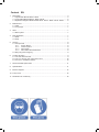 2
2
-
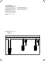 3
3
-
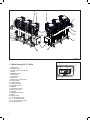 4
4
-
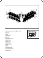 5
5
-
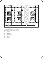 6
6
-
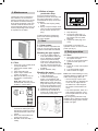 7
7
-
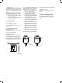 8
8
-
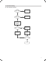 9
9
-
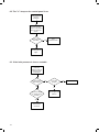 10
10
-
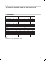 11
11
-
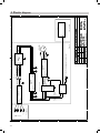 12
12
-
 13
13
-
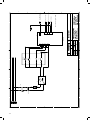 14
14
-
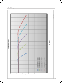 15
15
-
 16
16
-
 17
17
-
 18
18
-
 19
19
-
 20
20
-
 21
21
-
 22
22
-
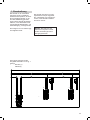 23
23
-
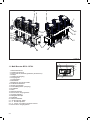 24
24
-
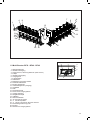 25
25
-
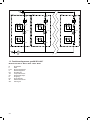 26
26
-
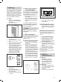 27
27
-
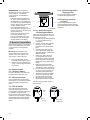 28
28
-
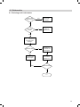 29
29
-
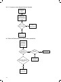 30
30
-
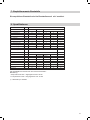 31
31
-
 32
32
-
 33
33
-
 34
34
-
 35
35
-
 36
36
-
 37
37
-
 38
38
-
 39
39
-
 40
40
-
 41
41
-
 42
42
-
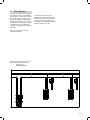 43
43
-
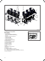 44
44
-
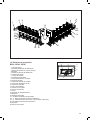 45
45
-
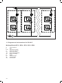 46
46
-
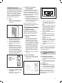 47
47
-
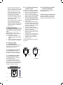 48
48
-
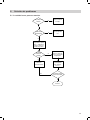 49
49
-
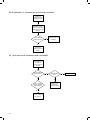 50
50
-
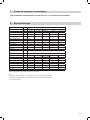 51
51
-
 52
52
-
 53
53
-
 54
54
-
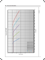 55
55
-
 56
56
-
 57
57
-
 58
58
-
 59
59
-
 60
60
-
 61
61
-
 62
62
-
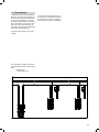 63
63
-
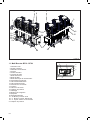 64
64
-
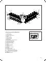 65
65
-
 66
66
-
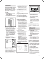 67
67
-
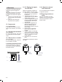 68
68
-
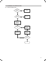 69
69
-
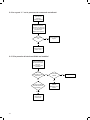 70
70
-
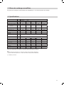 71
71
-
 72
72
-
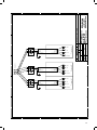 73
73
-
 74
74
-
 75
75
-
 76
76
-
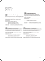 77
77
-
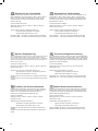 78
78
-
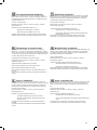 79
79
-
 80
80
-
 81
81
-
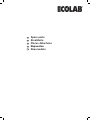 82
82
-
 83
83
-
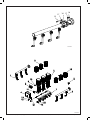 84
84
-
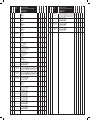 85
85
-
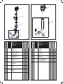 86
86
-
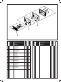 87
87
-
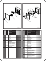 88
88
-
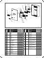 89
89
-
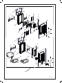 90
90
-
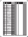 91
91
-
 92
92


en otros idiomas
- français: Ecolab BF16 Manuel utilisateur
Artículos relacionados
Otros documentos
-
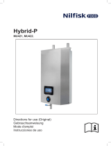 Nilfisk FOOD MU421 El manual del propietario
-
Nilfisk FOOD SU21 Manual de usuario
-
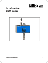 nilfiskfood SE11 Hybrid Eco-Satellite Manual de usuario
-
Nilfisk MIX 10-25 Manual de usuario
-
PCE VM 21 Video Microscope El manual del propietario
-
Sanus Systems BF24 Manual de usuario
-
iGuzzini 1570 Guía de instalación
-
-
-
Comet Patriot 150 Gold Manual de usuario

