Mi-T-M CAW Aluminum Series El manual del propietario
- Categoría
- Limpiadores de alta presión
- Tipo
- El manual del propietario

©Copyright 2018, Mi-T-M Corporation Form #37-1473-E/S-013120
CAUTION
RISK OF INJURY!
READ MANUAL BEFORE OPERATING!
This manual is an important part of the pressure washer and
must remain with this unit!
OPERATOR'S MANUAL FOR
CAW-2004-0ME1
CAW-2004-0ME3
CAW-3004-0ME1
CAW-3004-0ME3
CAW-4004-0ME1
COLD WATER ELECTRIC WALL MOUNT
PRESSURE WASHER

2 MI-T-M Electric Operator's Manual
TABLE OF CONTENTS
INTRODUCTION ...............................................................................................................................3
IMPORTANT SAFETY WARNINGS ..................................................................................................4
FEATURES (2004 AND 3004) ........................................................................................................... 8
FEATURES (4004) ............................................................................................................................9
SAFETY DECALS & PLACEMENT ................................................................................................10
INSTALLATION & PREPARATION ................................................................................................. 11
ATTIRE: .................................................................................................................................11
SETUP: ..................................................................................................................................11
POWER CORD CONNECTION: ...........................................................................................11
NOZZLE REVIEW: ..............................................................................................................12
NOZZLE CONNECTION: ......................................................................................................12
WATER SUPPLY: ..................................................................................................................13
UNLOADER: .......................................................................................................................... 13
THERMAL RELIEF VALVE: ...................................................................................................13
PRE-START INSPECTION PROCEDURES: ........................................................................14
OPERATING INSTRUCTIONS ........................................................................................................15
PRIMING THE PUMP: ........................................................................................................... 15
START-UP: ............................................................................................................................15
CLEANING WITH DETERGENTS: .......................................................................................16
SHUTDOWN: ........................................................................................................................16
TIME DELAY SHUTDOWN: ..................................................................................................16
AUTO START OPTION (CX-0069): .......................................................................................16
STORAGE & MAINTENANCE ........................................................................................................17
SPECIFIC MAINTENANCE: ..................................................................................................17
WINTERIZING: ......................................................................................................................17
STARTING UNIT AFTER EXTENDED STORAGE: ...............................................................18
WALL-MOUNT BRACKET INSTRUCTIONS .................................................................................. 19
UNIT WALL MOUNTING .................................................................................................................20
ELECTRIC BOX MOUNTING .......................................................................................................... 21
WALL MOUNTING INSTRUCTIONS ..............................................................................................22
MOUNTING THE SPACER & WALL BRACKETS: ................................................................22
MOUNTING UNIT ON BRACKETS: ......................................................................................22
MOUNTING HOSE HANGER BRACKET: .............................................................................22
MOUNTING ELECTRIC BOX: ............................................................................................... 22
TROUBLESHOOTING ....................................................................................................................23
STATEMENT OF WARRANTY ........................................................................................................25
WARNING: This product can expose you to
chemicals including Lead, which is known to
the State of California to cause cancer and birth
defects or other reproductive harm. For more
information go to www.P65Warnings.ca.gov
WARNING

MI-T-M Electric Operator's Manual 3
INTRODUCTION
Congratulations on the purchase of your pressure washer! You can be assured your pressure washer was construct-
ed and designed with quality and performance in mind. Each component has been rigorously tested to ensure the
highest level of acceptance.
This operator's manual was compiled for your benet. By reading and following the simple safety, installation, opera-
tion, maintenance and troubleshooting steps described in this manual, you will receive years of trouble free operation
from your pressure washer. The contents of this manual are based on the latest product information available at the
time of publication. The manufacturer reserves the right to make changes in price, color, materials, equipment, speci-
cations or models at any time without notice.
! IMPORTANT !
THESE PARAGRAPHS ARE SURROUNDED BY A "SAFETY ALERT BOX". THIS BOX IS USED
TO DESIGNATE AND EMPHASIZE SAFETY WARNINGS THAT MUST BE FOLLOWED WHEN
OPERATING THIS PRESSURE WASHER.
ACCOMPANYING THE SAFETY WARNINGS ARE "SIGNAL WORDS" WHICH DESIGNATE THE
DEGREE OR LEVEL OF HAZARD SERIOUSNESS. THE "SIGNAL WORDS" USED IN THIS
MANUAL ARE AS FOLLOWS:
DANGER: INDICATES AN IMMINENTLY HAZARDOUS SITUATION WHICH, IF NOT AVOIDED, WILL RESULT
IN DEATH OR SERIOUS INJURY.
WARNING: INDICATES A POTENTIALLY HAZARDOUS SITUATION WHICH, IF NOT AVOIDED, COULD
RESULT IN DEATH OR SERIOUS INJURY.
CAUTION:INDICATES A POTENTIALLY HAZARDOUS SITUATION WHICH, IF NOT AVOIDED MAY RESULT
IN MINOR OR MODERATE INJURY.
THE SYMBOLS SET TO THE LEFT OF THIS PARAGRAPH ARE "SAFETY ALERT SYMBOLS".
THESE SYMBOLS ARE USED TO CALL ATTENTION TO ITEMS OR PROCEDURES THAT COULD
BE DANGEROUS TO YOU OR OTHER PERSONS USING THIS EQUIPMENT.
ALWAYS PROVIDE A COPY OF THIS MANUAL TO ANYONE USING THIS EQUIPMENT. READ
ALL INSTRUCTIONS BEFORE OPERATING THIS PRESSURE WASHER AND ESPECIALLY
POINT OUT THE "SAFETY WARNINGS" TO PREVENT THE POSSIBILITY OF PERSONAL
INJURY TO THE OPERATOR.
Once the unit has been removed from the box, immediately write in the serial number of your unit in the space provided
below.
SERIAL NUMBER_________________________________
Inspect for signs of obvious or concealed freight damage. If damage does exist, le a claim with the transportation
company immediately. Be sure that all damaged parts are replaced and that the mechanical problems are corrected
prior to operation of the unit. If you require service, contact Customer Service at 800-648-8478.
Please have the following information available for all service calls:
1. Model Number
2. Serial Number
3. Date and Place of Purchase

4 MI-T-M Electric Operator's Manual
ELECTRICAL PRECAUTIONS:
RISK OF ELECTRIC SHOCK OR ELECTROCUTION:
WARNING
Serious injury or death could occur if the pressure washer is not prop-
erly grounded. Your pressure washer is powered by electricity and
may cause electric shock or electrocution if not used properly.
1. This product must be grounded. The pressure washer must be plugged
into a receptacle that is protected by a GFCI. Disconnect when not in
use.
2. Always be certain the unit is receiving proper voltage. Disconnect when
not in use.
WARNING
Electrical shock may occur from electrical cord.
3. Check power cord for signs of crushing, cutting or heat damage. If
replacement of cord is needed use only identical replacement parts
4. Keep all connections dry and off the ground. Do not allow electrical cords
to lay in water or in such a position where water could come in contact
with them.
WARNING
Electrical shock may occur if pressure washer is not operated proper-
ly.
5. DO NOT direct spray on or into electrical installations of any kind! This
includes electrical outlets, light bulbs, fuse boxes, transformers, the unit
itself, etc.
6. DO NOT allow metal components of the pressure washer to come in
contact with live electrical components.
7. Never operate the pressure washer with safety guards/covers removed
or damaged.
WARNING
Serious injury or death may occur if unqualied persons attempt elec-
trical repairs.
8. Any electrical wiring or repairs performed on this pressure washer should
be done by Authorized Service Personnel in accordance with National and
Local electrical codes.
9. Before opening any electrical enclosure, always shut off the pressure
washer, relieve pressure and unplug the pressure washer from the power
source. Allow the pressure washer to cool down. Never assume the
pressure washer is safe to work on just because it is not operating. It
could restart at any time! Service in a clean, dry, at area.
IMPORTANT SAFETY WARNINGS

MI-T-M Electric Operator's Manual 5
SPRAY PRECAUTIONS
DANGER
RISK OF INJECTION OR SEVERE CUTTING INJURY:
Keep clear of nozzle. Do not direct discharge stream at persons or
pets. When using this product, basic precautions should always be
observed, including the following:
1. Keep clear of the nozzle and spray! Never put your hand, ngers
or body directly over the spray nozzle.
2. Never point the high pressure spray at yourself or anyone else.
3. This product is to be used only by trained operators.
4. Always keep operating area clear of all persons.
5. Never allow children or adolescents to operate this unit.
6. SEEK EMERGENCY MEDICAL CARE if the spray appears to have
penetrated the skin! DO NOT TREAT AS A SIMPLE CUT!
7. High pressure hoses should be inspected daily for signs of wear. If
evidence of failure exist, promptly replace all suspect hoses to prevent
the possibility of injury from the high pressure spray. If a hose or tting
is leaking, NEVER PLACE YOUR HAND DIRECTLY ON THE LEAK.
8. NEVER operate the gun with the trigger wired in the open position. To
prevent accidental discharge, the trigger gun should be securely locked
when not in use.
9. Do not move the unit by pulling on the hose
10. Before removing the spray nozzle or servicing the unit, ALWAYS shut
off the unit and trigger the gun to release trapped pressure. (Even after
you shut off the unit, there is high pressure water left in the pump, hose
and gun until you release it by triggering the gun.)
11. Do not leave pressurized unit unattended. Shut off the pressure washer
and relieve trapped pressure before leaving.
MISCELLANEOUS SAFETY PRECAUTIONS
RISK OF EXPLOSION OR FIRE:
WARNING
Serious injury or death may occur from normal sparks in the motor
and electrical system.
1. DO NOT operate unit in an area where ammable gas vapors may be
present. An electric spark may cause an explosion or re.
2. DO NOT spray ammable liquids. Do not spray in an area containing
combustible dust, liquids or vapors.
RISK OF ASPHYXIATION:
WARNING
Serious injury or death may occur from inhaling dangerous vapors.
1. Follow all safety instructions provided with the materials you are spraying.
Use of a respirator may be required when working with some materials.
Do not use this pressure washer to dispense hazardous detergents.
IMPORTANT SAFETY WARNINGS

6 MI-T-M Electric Operator's Manual
MISCELLANEOUS SAFETY PRECAUTIONS, CONT'D.
RISK OF BURSTING:
WARNING
Serious injury may occur from a pressure washer malfunction or ex-
ploding accessories if incorrect system components, attachments or
accessories are used.
1. Never exceed manufacturers maximum allowable pressure rating of
attachments.
2. Use only manufacturer recommended repair parts for your pressure washer.
WARNING
Serious injury or death may occur if attempting to start the pressure
washer when the pump is frozen.
3. In freezing temperatures, the unit must always be warm enough to ensure
there is no ice formation in the pump. Do not start the pressure washer
if it has been transported in an open or underheated vehicle without rst
allowing the pump to thaw.
RISK FROM MOVING PARTS:
WARNING
Serious injury may occur to the operator from moving parts on the pres-
sure washer.
1. Do not operate the unit without all protective covers in place.
2. Before servicing the pressure washer, turn the unit off, disconnect from the
power source, relieve the water pressure and allow the unit to cool down.
Service in a clean, dry, at area.
3. Follow the maintenance instructions specied in the manual.
RISK OF BODILY INJURY:
WARNING
Serious injury can occur from loose debris being propelled at high
speed from the spray gun.
1. Always wear protective goggles when operating the unit to shield the eyes
from ying debris and detergents.
2. Do not direct spray toward fragile materials such as glass. Shattering could
result in serious injury.
WARNING
Injury may occur if the operator loses balance caused by the thrust of
water traveling through the spray nozzle.
1. Stay alert-watch what you are doing. Do not operate the unit when fatigued
or under the inuence of alcohol or drugs.
2. Never squeeze the trigger unless securely braced. DO NOT overreach or
stand on unstable support. Wet surfaces can be slippery, wear protective
foot gear and keep good footing and balance at all times. Never trigger the
gun while on a ladder or roof.
WARNING
INJURY MAY OCCUR FROM THE PRESSURE WASHER.
1. Always hold on rmly to the gun/lance assembly when starting and operating
the unit. Failure to do so can cause the lance to fall and whip dangerously.
2. Know how to stop the pressure washer and bleed pressures quickly. Be
thoroughly familiar with controls.
IMPORTANT SAFETY WARNINGS

MI-T-M Electric Operator's Manual 7
DETERGENT CLEANING PRECAUTIONS
RISK OF BODILY INJURY:
WARNING
Serious injury or death may occur from detergents contacting the
skin.
1. DO NOT use solvents, highly corrosive detergents or acid type cleaners
with this pressure washer. Use only mild detergents.
2. KNOW YOUR DETERGENTS! Be prepared to tell a physician exactly
what you are using in the event of an emergency. Read the Material
Safety Data Sheet (MSDS) provided with your detergent and all detergent
labels. Follow all appropriate instructions regarding preparation, use,
safety and transportation.
3. Protective equipment such as rubber suits, gloves and respirators are
advisable, especially when using cleaning detergents.
4. Keep all detergents out of the reach of children.
! SAVE THESE INSTRUCTIONS !
IMPORTANT SAFETY WARNINGS

8 MI-T-M Electric Operator's Manual
FEATURES (2004 AND 3004)
FEATURES LISTING
GC-2004_3004 W_REMOTE BOX FEATURES 110819 JJR
1. Pump
2. Water Inlet
3. Water Outlet
4. Adjustable Unloader Knob
5. Quick Connect Nozzle
6. High Pressure Discharge Hose
7. Gun Assembly
8. Power Cord W/ GFCI - 4 Foot (1 Ph)
Power Cord W/ Plug - 4 Foot (3 Ph)
9. ON/OFF Switch
10. Motor
4
2
1
10
7
6
5
3
98

MI-T-M Electric Operator's Manual 9
FEATURES (4004)
FEATURES LISTING
GC-4004 W_REMOTE BOX FEATURES 111819 JJR
1. Pump
2. Quick Connect Nozzle
3. Adjustable Unloader Knob
4. Water Outlet
5. Water Inlet
6. Gun Assembly
7. High Pressure Discharge Hose
8. ON/OFF Switch
9. Power Cord W/ GFCI - 4 Foot (1 Ph)
Power Cord W/ Plug - 4 Foot (3 Ph)
10. Motor
10
7
1
5
3
2
8 6
9
3

10 MI-T-M Electric Operator's Manual
SAFETY DECALS & PLACEMENT
DO NOT REMOVE SAFETY DECALS FROM UNIT UNLESS REPLACING WITH MOST CURRENT SAFETY DECAL!!
WARNING: Cancer and Reproductive Harm — www.P65warnings.ca.gov/
RISK OF ELECTROCUTION. DO NOT REMOVE THIS TAG.
ADVERTENCIA: Peligro de cáncer y daño reproductivo — www.P65warnings.ca.gov/
RIESGO DE ELECTROCUCION. NO RETIRE ESTA CALCOMANIA.
1. Conecte solamente a una toma corriente que está bien fundado. No quite la pata de conexión de la tierra.
2. Antes de usar inspeccióne la cuerda. No use si la cuerda està dañando.
3. Mantenga los conexiones secos y apar tados de la tierra.
4. No torque el enchufe con manos mojados.
5. Este producto debe conectarse a tierra. Asegúrese de que la lavadora a presión esté equipada con un Interruptor de circuito
de falla a tierra (Ground Fault Circuit Interrupter, GCIF) incorporado en el cordón de alimentación. Si no lo tiene, debe
conectarse la lavadora a presión únicamente en un receptáculo que esté protegido por un Interruptor de circuito de falla a
tierra. Desconéctela cuando no esté en uso.
6. No use una cuerda extensión con la unidad.
7. Antes de usar lea y entienda todas las instrucciónes y el manual de operación.
8. Riesgo de inyección o lesion severa: Mantenga la boquilla despe jada. No dirija el chorro hacía alguna persona o hacía usted.
9. Riesgo de electrocución: No dirija el rociado hacía conexiones o toma corrientes electricos.
10. Riesgo de explosion: No dirija el chorro hacía conexiones electricos. Tomas de corrientes o lineas de alimentacion de
corriente.
11. Riesgo de lesion: Mientras se opera esta unidad se recomiendan antiparras y protección apropriada. No use esta unidad
cerca de niños.
12. Riesgo de exposición química: Use usted solemente aqua y detergente con esta unidad.
13. Si la conexión se hace a un sistema de agua potable, el sistema será protegido contra la expulsión.
1. Connect only to a properly grounded outlet. Do not remove ground pin.
2. Inspect cord before using. Do not use if cord is damaged.
3. Keep all connections dry and off the ground.
4. Do not touch plug with wet hands.
5. This unit may be provided with a Ground Fault Circuit Interrupter (GFCI) built into the power cord plug. If replacement of
plug or cord is needed, use only identical replacement parts. If this unit is not provided with a GFCI, this unit should only
be connected to a power sutpply receptacle protected by a ground fault circuit interrupter.
6. Do not use an extension cord with this machine.
7. Read the operator's manual carefully before using.
8. Risk of Injection or Severe Injury to persons: Keep clear of nozzle. Do not touch or direct discharge stream at persons. This
machine is to only be used by qualified operators.
9. Risk of Electrocution: Do not direct spray toward any electrical connections or outlets.
10. Risk of Explosion: Do not spray flammable liquids. Do not spray in an area containing combustible dust, liquids or vapors.
11. Risk of Injury: Always wear proper safety attire including eye protection. Do not use this product when children are present.
12. Risk of Chemical Exposure: Use only water and recommended detergents with this unit.
13. If connection is made to a potable water system, the system shall be protected against backflow.
FAILURE TO FOLLOW THE ABOVE INSTRUCTIONS COULD RESULT IN A SEVERE ELECTRICAL SHOCK.
EL NO SEGUIR LAS INSTRUCCIONES DE ARRIBA PUEDE RESULTAR EN UN CHOQUE ELECTRICO GRAVE.
1. Para Reducir el Riesgo de que Ocurran Lesions: Lea y
entienda el manual de operacion y todas las instrucciones ante
de usar el producto.
2. Permanizca Alerta: Sostenga la pistola varilla firmenmente con
ambas mano para evitar golpes de retroceso peligrosos.
3. No se extienda demasiado o se pare en un apoyo inestable.
Mantenga una buena posicion y balance todo el tiempo.
4. Inspeccione las mangueras por dobleces, cortes y pérdidas.
5. Riesgo de que Ocular Lesions: Use siempre proteccion ocular.
6. Proteja la bomba de la congelacion.
7. Antes de comenzar. Abra sienpre el suminstro de agua a la
bomba.
8. Coloque el suguro del gatillo en la posicion apagado cuando no
este usando el producto.
9. Para uso interior. Almacene bajo techo.
10. Si se conecta a un circuito protegido por fusibles, use fusibles
con retardo solamente.
11. Para hacer los servicios, necesita desconectar la unidad del
circuito de suministro.
1. To Reduce Risk of Injury: Read and understand the operation
manual and all instructions before using.
2. Stay Alert: Hold onto gun/wand firmly with both hands to avoid
dangerous kickbacks.
3. Do not overreach or stand on unstable support. Keep good
footing and balance at all times.
4. Inspect all hoses for kinking, cuts and leaks.
5. Risk of Eye Injury: Always wear eye protection.
6. Protect pump from freezing.
7. Always turn on water supply to pump before starting.
8. Engage trigger safety lock-off when not in use.
9. For indoor use only. Store indoors.
10. If connected to a circuit protected by fuses, use time-delay
fuses only.
11. Servicing is to be done with the unit disconnected from the
supply circuit.
CONNECT TO AN INDIVIDUAL
BRANCH CIRCUIT ONLY.
34-3708/040518
ADVERTENCIA
WARNING
CAUTION PRECAUCION
CONECTE A UNA RAMA INTERRUPTOR
INDIVIDUAL SOLAMENTE.
Decal: Caution: Risk of Electrocution (Part # 34-3708)

MI-T-M Electric Operator's Manual 11
INSTALLATION & PREPARATION
ATTIRE:
Proper attire is essential to your safety. It is advised to utilize whatever
means necessary to protect eyes, ears, and skin. Additional safety attire
(such as respiratory mask) may be required when using detergent cleaning
agents with this washer.
SETUP:
1. This unit should only be placed on a level surface to ensure proper lubrication
for the water pump while operating. NEVER spray water directly on the
unit!
2. Do not place unit in an area:
a. where there is evidence of oil or gas leaks.
b. where ammable gas vapors may be present.
3. Do not allow the unit to be exposed to rain, snow or freezing temperatures.
If any part of the unit becomes frozen; excessive pressure may build up in
the unit which could cause it to burst, resulting in possible serious injury to
the operator or bystanders.
4. Before each use, be certain the oil level is in the center of the sight glass.
If low, ll with pump oil. DO NOT OVERFILL!
WARNING
RISK OF EXPLOSION!
DO NOT OPERATE UNIT IN AN
AREA WHERE FLAMMABLE GAS
VAPORS MAY BE PRESENT. AN
ELECTRIC SPARK MAY CAUSE
AN EXPLOSION.
RISK OF BURSTING!
DO NOT STORE / OPERATE UNIT
IN A FREEZING ENVIRONMENT.
DANGER
RISK OF ELECTROCUTION!
THIS UNIT MUST BE CONNECTED
TO A PROPERLY GROUNDED
OUTLET.
WARNING
RISK OF ELECTROCUTION!
TO REDUCE THE RISK OF
ELECTROCUTION, KEEP ALL
CONNECTIONS DRY AND OFF
THE GROUND.
WALL MOUNTING INSTRUCTIONS: SEE PAGE 20-22.
POWER CORD CONNECTION:
1. Make certain the motor switch is in the "OFF" position.
2. Ensure electrical supply is identical to the specications listed on the pressure
washer data plate.
3. GROUNDING INSTRUCTIONS: This product must be grounded. If it should
malfunction or breakdown, grounding provides a path of least resistance for
electric current to reduce the risk of electric shock. This product is equipped
with a cord having an equipment-grounding conductor.
4. DANGER: Improper connection of the equipment-grounding conductor can
result in a risk of electrocution. Check with a qualied electrician or service
personnel if you are in doubt as to whether the outlet is properly grounded.
5. GROUND FAULT CIRCUIT INTERRUPTER PROTECTION:
a. This pressure washer should only be connected to a receptacle that is
protected by a Ground Fault Circuit Interrupter (GFCI) to comply with the
National Electric Code (NFPA 70) and to provide additional protection
from the risk of electric shock.

12 MI-T-M Electric Operator's Manual
NOZZLE REVIEW:
Various nozzles may be quick-connected into the end of the wand to change
the spray pattern or use the detergent feature. When using Quick Connects
(Q.C.), be certain the connection is securely locked. If not, the high pressure
water may shoot the nozzle from the wand, causing severe injury or serious
damage. To determine spray fan, refer to the actual number stamped on the
nozzle. The rst two digits indicate the spray fan in degrees, i.e.; 00=0°,
15=15°, 25=25°, 40=40°, 65=detergent/low pressure.
1. The 0° nozzle (RED): This is a blasting nozzle. It delivers a very concentrated
stream of water. Be cautious when using the straight narrow stream. It is
not recommended for use on painted or wood surfaces, or items attached
with adhesive backings. Uses: Removing weeds from sidewalk cracks,
stubborn stains from concrete, masonry, aluminum and steel, caked mud
from equipment, and cleaning lawn mower undersides.
2. The 15° nozzle (YELLOW): This is a chiseling nozzle. The spray should
be directed at a 45° angle to the surface and used like a scraper to remove
paint, grease and dirt. Uses: Surface preparation (removing mildew stains
and paint chips).
3. The 25° nozzle (GREEN): This is a ushing nozzle. This pattern is best
suited for ushing dirt, mud, and grime. Uses: Wet sweeping leaves from
walks, curbs and driveways, cleaning stable oors, washing swimming pool
bottoms, degreasing engines.
4. The 40° nozzle (WHITE): This is a wash nozzle. This wide spray pattern
disperses the water pressure over a large area and is recommended for
moderate washing. Uses: Washing aluminum siding, cleaning windows,
washing vehicles, spraying sidewalks, driveways, and patios.
5. The 65° nozzle (BLACK): This is a low pressure detergent application
nozzle. This broad spray pattern distributes solution over vast areas under
low pressure. Uses: Detergent application, misting or rinsing.
NOZZLE CONNECTION:
1. Be certain the trigger gun is locked in the "OFF" position. See WARNING,right.
2. The nozzle assembly should be disconnected from the gun/wand assembly
at this by retracting the locking ring on the quick-connect tting to remove
the nozzle.
WARNING
RISK OF INJECTION CAUSING
SEVERE INJURY!
NEVER LOOK DIRECTLY AT THE
NOZZLE ORIFICE UNLESS IT IS
DISCONNECTED FROM THE
GUN/WAND ASSEMBLY!
CONNECTION OF Q.C. NOZZLES
QUICK-CONNECT (Q.C.)
INSTALLATION & PREPARATION
WARNING
RISK OF SEVERE INJURY!
THE TRIGGER GUN SHOULD
ALWAYS BE LOCKED IN THE OFF
POSITION WHEN NOT IN USE!
QUICK-CONNECT FITTING

MI-T-M Electric Operator's Manual 13
CAUTION
RISK OF UNIT DAMAGE!
DO NOT OVERTIGHTEN THE
UNLOADER. BREAKAGE WILL
RESULT IN IMMEDIATE LOSS OF
WATER PRESSURE AND COSTLY
REPAIRS.
WATER SUPPLY:
1. Select a water supply hose which is a quality grade of garden hose measuring
at least 3/4" ID and no longer than 50 feet.
2 Check the water inlet strainer to ensure it is clean and free of any obstructions.
Periodic cleaning of the water strainer will help prevent pump problems. As
a strainer becomes obstructed, it restricts proper ow of water to the pump.
This can cause cavitation which will result in premature failure of pump
packings and valves. Using a screw driver, remove the screen; clean or
replace if necessary.
3. Connect the hoses.
a. Connect one end of the water supply hose to the water inlet of the unit.
b. Connect the other end of the hose to your pressurized water supply.
NOTE: Do not use a non-pressurized water supply (i.e. from a well or
pond) with this unit.
c. Connect the high pressure discharge hose to the water outlet of the unit.
4. Follow the incoming water requirements listed below:
a. Water pressure must be a minimum of 20 pounds per square inch (PSI)
and a maximum of 125 PSI. (A typical outdoor faucet will generally
supply this PSI if turned completely "ON".)
b. Incoming GPM must be approximately one gallon more than the outgoing
GPM stated on the pressure washer nameplate. (You can check GPM
by timing how long it takes to ll a 5 gallon container.
c. Incoming water temperature must not exceed 165°F (74°C). Excessive
pump damage may result if the water temperature exceeds this
acceptable level.
5. Never allow the unit to operate without the incoming water line attached and
the water supply turned all the way on.
UNLOADER:
The unloader valve on your machine is equipped with an adjustment knob to
adjust the pressure. Should less pressure be required, simply turn the adjust-
ment knob counterclockwise. To set back to maximum, turn adjustment knob
completely clockwise. DO NOT OVERTIGHTEN!
THERMAL RELIEF VALVE:
To ensure the water temperature does not exceed acceptable levels, never al-
low the pressure washer to operate in the bypass mode (with the unit running
and the trigger closed) for more than three minutes.
A thermal relief valve has been added to this unit to protect the pump. This
valve will open and release water if the water temperature in the pump has
exceeded 190° F (87°C). This will allow fresh, cool water to enter the system,
preventing premature failure of pump packings.
INSTALLATION & PREPARATION
CHECK WATER INLET STRAINER

14 MI-T-M Electric Operator's Manual
PRE-START INSPECTION PROCEDURES:
Before starting the unit, perform the following procedures:
1. Inspect electrical cord for cuts. If a cut is found, DO NOT TOUCH OR USE
ELECTRICAL CORD! Replace cord before starting the unit.
2. Check the oil level in the pump.
3. Inspect the inlet water strainer. Clean or replace if necessary. See "Water
Supply", #2, pg. 12.
4. Check all hose connections to ensure they are securely tightened. See
"Water Supply", #3, pg. 12.
5. Inspect for system water leaks and oil leaks. Be sure that all damaged
parts are replaced and that the mechanical problems are corrected prior to
operation of the unit. If service is needed, contact Customer Service.
6. Inspect high pressure hose for kinking, cuts or leaks. If a cut or leak is
found, DO NOT USE HOSE! Replace hose before starting unit. Be sure
that all damaged parts are replaced and that the mechanical problems are
corrected prior to operation of the unit. If you need service, contact Customer
Service.
INSTALLATION & PREPARATION
END OF PREPARATION INSTRUCTIONS
WARNING
THE FOLLOWING PAGES CONTAIN OPERATING AND MAINTENANCE
INSTRUCTIONS
DO NOT ATTEMPT TO OPERATE THIS PRESSURE WASHER UNTIL YOU HAVE
READ AND UNDERSTOOD ALL SAFETY PRECAUTIONS AND INSTRUCTIONS
LISTED IN THIS MANUAL.
INCORRECT OPERATION OF THIS UNIT CAN CAUSE SERIOUS INJURY!!
DO NOT ALTER OR MODIFY THIS EQUIPMENT IN ANY MANNER!

MI-T-M Electric Operator's Manual 15
PRIMING THE PUMP:
1. It is essential to prime the pump on initial start-up and each time the water
supply is disconnected from the unit after initial use.
2. Lay the high pressure hose out to remove any loops. Water ow will constrict
the hose, creating tight loops if the hose is not straight.
3. Securely connect the gun assembly to the high pressure hose.
NOTE: The nozzle should NOT be connected to the gun assembly at this
time. See "Nozzle Connection" pg. 13.
4. With the trigger gun locked in the "OFF" position, turn the water supply
completely on. Pointing the gun in a safe direction, unlock the trigger gun
and squeeze the trigger.
5. Low pressure water will begin owing from the hose/gun assembly. This
allows the unit to prime and purge any air from the system. The unit is
primed when water ow is uninterrupted by air.
6. Once the unit is primed, release the trigger and lock the gun in the "OFF"
position. Securely connect the nozzle assy. (See "Nozzle Connection" pg.
13)
START-UP:
1. Refer to the "Safety Precautions" pgs. 4-7 before starting the unit.
2. Locate the Safety Decals on your unit and heed their warnings.
3. With the gun locked in the "OFF" position, point the trigger gun away from
yourself or anyone else. Ensure water supply is turned completely on.
4. Disengage the safety lock-off on the gun and squeeze the trigger. Low
pressure water will begin owing from the nozzle.
5. Before starting the unit, brace yourself as the gun will kickback from the
high pressure created by the pump once the unit has started.
6. Move the switch to the "ON" position.
7. Once the unit is turned on, perform the following procedures with the gun
open:
a. Inspect for system water leaks and oil leaks. If a leak is found, TURN
UNIT OFF IMMEDIATELY! Be sure that all damaged parts are replaced
and that the mechanical problems are corrected prior to operation of the
unit. If you require service, contact Customer Service.
b. Inspect high pressure hose for kinking cuts and leaks. If a cut or leak is
found, DO NOT TOUCH HOSE AT CUT OR LEAK!!! TURN UNIT OFF
IMMEDIATELY! Replace hose before restarting the unit. Be sure that
all damaged parts are replaced and that the mechanical problems are
corrected prior to operation of the unit. If you require service, contact
Service.
c. Inspect electrical cord for cuts. If a cut is found, DO NOT TOUCH
OR USE ELECTRICAL CORD! Replace cord before starting the
unit.
8. Trigger the gun several times. Be certain to LOCK the trigger gun in the
"OFF" position whenever changing the nozzle. NEVER look directly into
the nozzle! High pressure water creates a risk of severe injury!
9. Do not allow unit to operate in bypass mode (with trigger closed) for more
than three minutes without triggering the gun. Failure to follow this simple
rule can cause premature failure of pump packing seals, resulting in costly
pump repair.
10. Because your pressure washer delivers a high pressure spray and a variety
of spray patterns, there are many cleaning jobs that can be done without
the use of detergents. If a cleaning agent is required, see "Cleaning With
Detergents" pg. 17 for the correct procedures.
CAUTION
RISK OF DAMAGE.
DO NOT ALLOW SPRAY PATTERN
TO REMAIN ON A FIXED AREA
FOR AN EXTENDED PERIOD OF
TIME. POSSIBLE DAMAGE MAY
OCCUR TO THE AREA.
WARNING
RISK OF INJECTION CAUSING
SEVERE INJURY!
-KEEP CLEAR OF NOZZLE!
NEVER PLACE HAND OR
FINGERS IN FRONT OF NOZZLE!
-DO NOT DIRECT DISCHARGE
STREAM AT PEOPLE OR PETS!
-BE CERTAIN THE NOZZLE IS
SECURELY CONNECTED TO
THE WAND TO PREVENT AN
ACCIDENTAL DISCHARGE!
OPERATING INSTRUCTIONS

16 MI-T-M Electric Operator's Manual
CLEANING WITH DETERGENTS:
1. Refer to "Detergent Cleaning Precautions" pg. 7 before working with
detergents. Be certain to wear protective safety attire as stated on pg. 10.
2. Quick connect the detergent injector between the unit outlet and the high
pressure hose.
3. Prepare detergent solution according to label directions. Never pump acids,
alkaline, abrasive uids or solvents through the unit.
4. Your injector is equipped with an adjustment knob, you may adjust the amount
of detergent desired by turning the knob completely counterclockwise to
set at the maximum siphon rate.
5. Immerse the detergent strainer into the detergent solution to allow detergent
to siphon.
6. Turn the pressure control handle counterclockwise to lower pressure and
divert water ow through the soap nozzle.
NOTE: This injection system is designed to apply detergents under low
pressure only. It will not allow detergent solutions to be introduced
into the system in high pressure mode.
7. To apply solution; unlock the trigger gun and squeeze the trigger. In a
few moments a detergent/water mixture will exit the low pressure nozzle.
Start spraying the lower portion of the surface being cleaned and move up,
using long overlapping strokes. Applying from the bottom up helps avoid
streaking. Allow to soak briey. DO NOT allow detergent solution to dry on
the surface. (Avoid working on hot surfaces or in direct sunlight to minimize
the chances of the detergent drying, which may result in damaging painted
surfaces.) Be certain to rinse a small section at a time.
8. When you nish washing, rinse by simply turning the variable pressure
control handle clockwise. It will take about 30 seconds to purge all detergent
from the line. For best rinsing results, start at the top and work down.
9. Siphon a gallon of water through the low pressure detergent injection
system after each use. This prevents the possibility of corrosion or detergent
residue causing mechanical problems during the next use.
SHUTDOWN:
1. Move the switch to the "OFF" position to turn unit off.
2. Turn the water supply off.
3. Pointing the gun in a safe direction, trigger the gun momentarily to relieve
any trapped pressure.
4. Once pressure is relieved, disconnect the nozzle.
5. Disconnect the unit from the power source.
6. Disconnect and drain gun, wand and hoses.
7. Wipe unit clean and store with gun, wand and hoses in a safe area.
TIME DELAY SHUTDOWN:
Once the spray gun trigger is released, the shutdown timer becomes activat-
ed. The machine will continue to run in bypass mode until the timer reaches
its preset time, 2-3 minutes. When that time is reached, the machine shuts
down. To reset, push the pump switch to the "ON" position.
AUTO START OPTION (CX-0112):
Units equipped with CX-0069 Option, Auto Start, will operate similar to the
standard time delay shutdown with the exception that the unit will automat-
ically restart when the gun trigger is engaged. The gun trigger lock should
always be locked in the off position when not in use. This unit is to be shut
down after use by turning the on/off switch on the control panel to the off
position.
QUICK CONNECT DETERGENT
OPERATING INSTRUCTIONS

MI-T-M Electric Operator's Manual 17
SPECIFIC MAINTENANCE:
PUMP: The pump oil must be changed after the rst 25 hours of opera-
tion. Once the initial oil change has been completed, it is recommended
the oil be changed every 3 months or 250 hour intervals. If oil appears
dirty or milky, changes may be required at a greater frequency. Use
specied pump oil and ll only to the center of the oil sight glass. DO
NOT OVERFILL!
NOZZLES: Water ow through the spray nozzle will erode the orice,
making it larger, resulting in a pressure loss. Nozzles should be replaced
whenever pressure is less than 85% of the maximum. The frequency of
replacement will depend upon such variables as mineral content in the
water and number of hours the nozzle is used.
QUICK COUPLERS: There is an o-ring seal inside the female quick
coupler. This o-ring will deteriorate or, if the unit is allowed to pump with-
out the high pressure hose or nozzle attached, the o-ring may be blown
out occasionally. Simply insert a replacement o-ring to correct the leak.
(Additional o-rings can be purchased from your dealer.)
WINTERIZING:
For storage and transportation purposes in subfreezing ambient tempera-
tures, it will be necessary to winterize this unit. This unit must be protected to
the lowest incurred temperature for the following reasons:
1. If any part of the pumping system becomes frozen; excessive pressure may
build up in the unit which could cause the unit to burst resulting in possible
serious injury to the operator or bystanders.
2. The pumping system in this unit may be permanently damaged if frozen.
FREEZE DAMAGE IS NOT COVERED BY WARRANTY.
If you must store your unit in an area where the temperature may fall below
32°F, you can protect your unit by following the procedure outlined below.
1. Gather the following items:
a. Two 5 gallon containers.
b. One gallon of antifreeze. (The manufacturer recommends an
environmentally safe antifreeze.)
c. Water supply.
d. Three foot hose, 1/2-3/4 I.D. with a 3/4 inch male garden hose tting.
2. Procedure:
a. To start winterizing, unit must be run and primed according to the "Start-
up Procedures" listed on page 16.
b. After running and priming, shut off the unit and water supply.
c. Relieve system pressure by pointing the trigger gun in a safe direction
and squeezing the trigger until water ow ceases to exit the nozzle.
d. Lock the trigger gun in an OFF position and remove the nozzle.
e. Remove the water supply hose from the unit and attach the 3 foot hose
securely to the inlet connection.
f. Shut off the detergent injector if applicable.
g. Fill one 5 gallon bucket with water.
h. Holding the 3 foot hose in an upright position, completely ll the hose
with water. Then plug the hose outlet with your thumb or nger. Place
the plugged end into the 5 gallon bucket of water.
i. Turn the unit on. Trigger the gun several times until all the air is worked
out of the system (unit is primed).
WARNING
RISK OF UNIT BURSTING!
DO NOT STORE OR OPERATE
UNIT IN A FREEZING ENVIRON-
MENT!
32˚F 0˚C
STORAGE & MAINTENANCE

18 MI-T-M Electric Operator's Manual
NOTE: Proper winterizing is based on the recommended manufacturer's
instructions listed on the "Protection Chart" shown on the back label
of most antifreeze containers.
j. With the trigger gun held open, siphon enough water out of the 5 gallon
bucket until there is just enough water left to mix with the antifreeze.
k. Point the wand into the empty container and start the unit.
l. Trigger the gun until the antifreeze begins to exit the wand. Release
the trigger for 3 seconds, then trigger the gun for 3 seconds. Continue
cycling the gun several times until all the antifreeze mixture is siphoned
from the container.
m. Detach the 3 foot hose from the unit and drain any excess antifreeze
back into the 5 gallon container.
n. Disconnect the hose/gun/wand assembly from the unit and drain any
excess antifreeze back into the 5 gallon container.
o. Store the hose, gun and wand with the unit in a safe area.
p. Store antifreeze solution for next use or dispose of according to state
EPA laws.
3. Optional Procedure:
a. Shut the unit off.
b. Relieve system pressure by pointing the trigger gun in a safe direction
and squeezing the trigger until water ow ceases to exit the nozzle.
c. Disconnect and drain the hose, gun and wand.
d. Start the unit and allow it to run until all the water exits the unit. Once
the water has stopped owing from the unit, turn off.
NOTE: When using this procedure, caution should be used as ice chips
can form from drops of water which could cause the unit to burst if
starting before completely thawed.
STARTING UNIT AFTER EXTENDED STORAGE:
1. BE CERTAIN the unit is NOT plugged into the power source.
2. Prior to restarting the unit, thaw out any possible ice from the wand, gun,
hose and unit.
3. After following all "PREPARATION" instructions, start the unit momentarily
and immediately turn "OFF" to ensure all parts are lubricated before
operation.
STORAGE & MAINTENANCE

MI-T-M Electric Operator's Manual 19
WALL-MOUNT BRACKET INSTRUCTIONS
PLEASE READ ENTIRE INSTALLATION INSTRUCTIONS BEFORE INSTALLATION!
Listed below are the contents of the Wall-Mount Bracket Kit. The included bolts (4), nuts (5) and washers (6) are for
mounting the support brackets to the unit frame only. Due to the unique circumstances of each installation, the
installer will be responsible for the hardware to secure the unit to the mounting surface.
The wall mount kit is to be attached to a wall or structure capable of handling a 750-pound minimum weight
load, such as a 4 x 4 studded wood structure or minimum 1/4 inch steel studded structure and/or framing.
A licensed building contractor should perform mounting of the bracket to a wall to assure proper strength of
support.
ITEM PART # DESCRIPTION QTY
1 13-0237 WALL MOUNT BRACKET 2
2 13-0238 SPACER BRACKET 1
3 13-0240 HOSE HANGER BRACKET 2
4 27-0067 BOLT 8
5 28-0003 WASHER 16
6 30-0157 NUT 8

20 MI-T-M Electric Operator's Manual
UNIT WALL MOUNTING
Figure 1: Hole pattern for 2004 and
3004 units
Figure 2: Hole pattern for
4004 units
Determine a location to install the unit with an appropriate amount of space for the unit and mounts with proper clear-
ances away from other objects or hazards. Allow plenty of space to t the pressure washer above his hole pattern.
12.75
"
DRAWING IS NOT TO SCALE
HOLE PATTERN FOR REFERENCE ONLY
2.50" TYP.
1.25" TYP.
16.00"
16.00"

MI-T-M Electric Operator's Manual 21
ELECTRIC BOX MOUNTING
Determine a location to install the unit with an appropriate amount of space for the unit and mounts with proper clear-
ances away from other objects or hazards. Allow plenty of space to t the pressure washer above his hole pattern.
Figure 3: Hole pattern for Electric box 6 and 8 HP units
Figure 4: Hole pattern for Electric box 10 HP units
7.00"
11.25
"
DRAWING IS NOT TO SCALE
HOLE PATTERN FOR REFERENCE ONLY
9.00"
13.25
"
DRAWING IS NOT TO SCALE
HOLE PATTERN FOR REFERENCE ONLY

22 MI-T-M Electric Operator's Manual
WALL MOUNTING INSTRUCTIONS
MOUNTING THE SPACER & WALL BRACKETS:
Using the hole pattern for the unit being installed, mark and drill the holes. Mount the Spacer Bracket (2) to the wall
in the top set of holes. Mount the Wall Mount Brackets (1) to the wall in the bottom set of holes.
MOUNTING UNIT ON BRACKETS:
Using proper personnel and/or equipment to lift unit, set the unit on the Spacer Bracket (2). Continue to hold unit up
while the baseplate is bolted to the Spacer Bracket using Items 4, 5 & 6 provided. These may be left loose until all
nuts and bolts are started. Secure the Wall Mount Brackets (1) to the baseplate using the remaining nuts and bolts
(4, 5 &6). Tighten all nuts and bolts. Check to be sure the unit is secure before operating.
CAUTION: These units can be heavy, ensure proper personnel and/or equipment is available for lifting and
securing!
MOUNTING HOSE HANGER BRACKET:
The Hose Hanger Bracket (3) may be mounted to any of the 2.50” x 1.25” rectangular hole sets on the front of the
Unit’s Baseplate or the bottom of the Wall Mount Brackets (1). For ease of mounting, two bolts may be put through
the lower right and upper left holes to keep unit more secure while
mounting the Hose Hanger Bracket. It is recommended that washers
not be used on those bolts. Slip the Hose Hanger Bracket over the bolt
heads of the rst two bolts and line up with the other two holes and bolt
them in.
NOTE: The two bolts in the upper right and lower left of the hole
set where the Hose Hanger Bracket (3) is mounted may need
to be longer to compensate for the extra material thickness.
This hardware is unique to each installation will need to be
obtained by the installer prior to installation.
MOUNTING ELECTRIC BOX:
Using the hole pattern for the Electric Box being installed, mark and
drill the holes. Locate Electric Box in a convienient location on the wall
for easy access and troubleshooting.
Figure 6: Unit sitting on Spacer Bracket (2) and Wall Mount
Bracket (1)
Figure 5: Mounting Unit on Spacer Bracket (2)

MI-T-M Electric Operator's Manual 23
TROUBLESHOOTING
SYMPTOM PROBABLE CAUSE REMEDY
Pump motor will not start, or
stops while operating.
Circuit overload. Tripped circuit breaker
or fuse blown in circuit fuse box.
Disconnect all other plugs on the circuit
being used and reset circuit breaker OR
check and replace fuse.
Tripped circuit breaker in unit. Allow to cool and restart unit.
Motor overload. Reset thermal overload button on pump
motor or inside electrical control panel.
Unit is frozen. Allow to thaw. If any part of the unit be-
comes frozen; excessive pressure may
build up in the unit which could cause
the unit to burst resulting in possible seri-
ous injury to the operator or bystanders.
Circuit breaker trips or fuse
blows in the box.
Circuit overload. Ensure electrical supply is identical fuse
to the specications listed on the pres-
sure washer data plate. Disconnect all
plugs on the circuit. When connecting
to a circuit protected by fuses, use time
delay fuses only.
Too much pressure. Use Adjusting Knob on Unloader to re-
duce pressure.
GFCI trips. Incorrect voltage. Ensure electrical supply is identical to
the specications listed on the pressure
washer data plate.
Electrical short to ground. Contact Customer Service.
Motor runs but there is no dis-
charge at nozzle when trigger
mechanism is squeezed.
Motor runs but there is no discharge. Turn water supply completely on.
Kink in water inlet hose. Remove kink.
Kink in high pressure discharge hose. Replace hose.
Low or uctuating pressure. Water inlet screen obstructed. Remove screen, clean or replace.
Pump sucking air. (Prime lost) Tighten all water intake connections.
Eliminate leaks in intake line.
Not in high pressure mode. Insert high pressure nozzle.
Obstructed or worn orice. Remove and clean, or replace.
Damaged or obstructed valve assembly
on pump.
Remove, clean or replace.
Pump packings worn. Replace packings.
Unloader valve not operating correctly. Repair or replace.
Water is leaking from Thermal
Relief Valve.
Water inlet temperature is too high. Incoming water temperature must be
less than 140°F.
Water temperature in unit is too high. Do not allow unit to operate in bypass
mode (with the trigger gun closed) for
more than three minutes.
Defective valve. Replace.

24 MI-T-M Electric Operator's Manual
SYMPTOM PROBABLE CAUSE REMEDY
Oil appears milky or foamy. Water in oil. Change pump oil. Fill to proper level.
Oil leaking from unit. Worn seals or o-rings. Contact Customer Service.
Detergent will not siphon
into Low Pressure Detergent
mode.
Detergent strainer is not completely sub-
merged in detergent solution.
Check; submerge if necessary.
Detergent strainer is obstructed. Inspect, clean or replace.
Detergent hose is obstructed, cut or
kinked.
Inspect, clean or replace.
Detergent adjusting knob turned to the
closed position.
Open adjusting knob.
Not in Low Pressure mode. Insert 6540° (BLACK) nozzle.
Nozzle assembly is plugged. Open adjusting knob.
Too many high pressure hose extensions
attached to the water outlet.
Use one extension maximum.
Ball & Spring in detergent strainer stuck. Remove, clean or replace.
Water ows back into deter-
gent container.
Ball & Spring in Venturi reversed, miss-
ing or corroded.
Remove, clean or replace.
Water ows from the nozzle
when the trigger gun is in the
"OFF" position.
Gun is malfunctioning. Repair or replace.
TROUBLESHOOTING

MI-T-M Electric Operator's Manual 25
STATEMENT OF WARRANTY
The manufacturer warrants all parts, (except those referred to below), of your new pressure
washer to be free from defects in materials and workmanship during the following periods:
For Lifetime against freezing and cracking:
Pump Manifold
For Five (5) Years from the date of original purchase:
High Pressure Pump
For Two (2) Years from the date of original purchase:
Frame Assembly
Plumbing
For One (1) Year from the date of original purchase:
Selector Switch
For Ninety (90) days from the date of original purchase:
Trigger Gun/Wand High Pressure Hose
Unloader Valve Strainer/lter
Defective parts not subject to normal wear and tear will be repaired or replaced at our option
during the warranty period. In any event, reimbursement is limited to the purchase price paid.
EXCLUSIONS
1. The motor is covered under separate warranty by its respective manufacturer and is
subject to the terms set forth therein.
2. Normal wear parts:
Pump Packings Spray Nozzles
Pump Valves Detergent Valves
Quick Couplings/Screw Connects O-rings
3. This warranty does not cover parts damaged due to normal wear, misapplication, misuse,
operation at other than recommended speeds, pressures or temperature. Parts damaged
or worn because of the use of caustic liquids or by operation in abrasive or corrosive
environments or under conditions causing pump cavitation are not warranted. Failure
to follow recommended operating and maintenance procedures also voids warranty.
4. The use of other than genuine manufactured repair parts will void warranty. Parts
returned, prepaid to our factory or to an Authorized Service Center will be inspected
and replaced free of charge if found to be defective and subject to warranty. There
are no warranties which extend beyond the description of the face hereof. Under no
circumstances shall the manufacturer bear any responsibility for loss of use of the unit,
loss of time or rental, inconvenience, commercial loss or consequential damages.
For Service or Warranty Consideration, contact Customer Service.
563-556-7484 / 800-553-9053 / Fax 563-556-1235
Monday - Friday 8:00 a.m. - 5:00 p.m. CST

26 GC Eléctrico Manual de Operador
ADVERTENCIA: Este producto puede
exponerlo a productos químicos, incluido el
plomo, que el Estado de California conoce a
causar cáncer y defectos congénitos u otros
daños reproductivos. Para obtener más
información, visite www.P65Warnings.ca.gov
ADVERTENCIA
TABLA DE MATERIAS
INTRODUCCION .............................................................................................................................27
ADVERTENCIAS DE SEGURIDAD ................................................................................................28
CARACTERISTICAS (2004 Y 3004) ...............................................................................................32
CARACTERISTICAS (4004) ...........................................................................................................33
CALCOMANIAS DE SEGURIDAD Y UBICACION ......................................................................... 34
INSTALACION Y PREPARACION ..................................................................................................35
PROTECCIÓN PERSONAL: .................................................................................................35
PREPARACIÓN: .................................................................................................................... 35
CONEXIÓN DEL CABLE DE ALIMENTACIÓN ELÉCTRICA: ...............................................35
BOQUILLA DE CONEXION RAPIDA: ..................................................................................36
CONEXION DE LA BOQUILLA: ............................................................................................36
SUMINISTRO DE AGUA: ......................................................................................................37
DESCARGADOR: .................................................................................................................37
VALVULA DE DESCARGA TERMICA: ..................................................................................37
PROCEDIMIENTOS DE INSPECCION DE PREARRANQUE: .............................................38
CEBADO DE LA BOMBA: .....................................................................................................39
ARRANQUE: .........................................................................................................................39
INSTRUCCIONES DE OPERACION ..............................................................................................39
LIMPIEZA CON DETERGENTES .........................................................................................40
APAGADO: ............................................................................................................................40
TIEMPO RETRASO APAGADO: ...........................................................................................41
OPCIÓN DE AUTOENCENDER (CX-0069): .........................................................................41
ALMACENAMIENTO Y MANTENIMIENTO ....................................................................................42
MANTENIMIENTO ESPECIFICO: .........................................................................................42
PREPARACION PARA EL INVIERNO: ..................................................................................42
ARRANQUE DE LA UNIDAD DESPUES DE UN ALMACENAMIENTO PROLONGADO: ...43
INSTALACIÓN DEL MONTAJE DE PARED ...................................................................................44
INSTRUCCIONES DE MONTAJE EN PARED DE LA UNIDAD .....................................................45
INSTRUCCIONES DE MONTAJE DE CAJA ELÉCTRICA ............................................................. 46
INSTALACIÓN DEL MONTAJE DE PARED ...................................................................................47
MONTAR DEL ESPACIADOR Y LOS SOPORTES DE MONTAJE DE PARAD: ...................47
MONTAR DEL ESPACIADOR Y LOS SOPORTES DE MONTAJE DE PARAD: ...................47
MONTAR EL SOPORTE DE LA SUSPENSIÓN DE LA MANGUERA: .................................. 47
MONTAJE DE CAJA ELÉCTRICA: .......................................................................................47
LOCALIZACION DE FALLAS ......................................................................................................... 48
DECLARACIÓN DE GARANTÍA ....................................................................................................50

GC Eléctrico Manual de Operador 27
INTRODUCCION
¡Felicitaciones por la compra de su nueva lavadora a presión! Puede estar seguro que su lavadora a presión fue con-
struida con el nivel más alto de precisión y exactitud. Cada componente ha sido probado rigurosamente por técnicos
para asegurar la calidad, la resistencia y el rendimiento de esta unidad.
Este manual del operador fue compilado para su benecio. Leyendo y siguiendo los pasos simples de seguridad, in-
stalación, operación, mantenimiento y localización de fallas descritos en este manual ayudará a prolongar aun más la
operación libre de fallas que usted puede esperar de su nueva lavadora a presión. El contenido de este manual está
basado en la información actualizada disponible al momento de la publicación. El fabricante se reserva el derecho de
efectuar cambios en precio, color, materiales, equipo, especicaciones o modelos en cualquier momento sin previo
aviso.
¡IMPORTANTE!
Estos párrafos están rodeados por una “CASILLA DE ALERTA DE SEGURIDAD”. Esta casilla
se usa para designar y enfatizar las Advertencias de Seguridad que deben seguirse al operar
esta lavadora a presión. Acompañando a las Advertencias de Seguridad están las “palabras
de alerta” que designan el grado o nivel de seriedad de riesgo. Las “palabras de alerta”
usadas en este manual son las siguientes:
PELIGRO: Indica una situación inminente riesgosa la cual, si no se evita, RESULTARA
en la muerte o en lesiones graves.
ADVERTENCIA: Indica una situación potencialmente riesgosa la cual, si no se evita, PODRIA
resultar en la muerte o en lesiones graves.
PRECAUCION: Indica una situación potencialmente riesgosa la cual, si no se evita PUEDE
resultar en lesiones menores o moderadas.
El símbolo indicado a la izquierda de este párrafo es el “Símbolo de Alerta de Seguridad”.
Este símbolo se usa para alertarlo acerca de artículos o procedimientos que podrían ser
peligrosos para usted u otras personas usando este equipo.
PROVEA SIEMPRE UNA COPIA DE ESTE MANUAL A CUALQUIER PERSONA QUE USE
ESTE EQUIPO. LEA TODAS LAS INSTRUCCIONES ANTES DE OPERAR ESTA LAVADORA A
PRESION, OBSERVANDO EN PARTICULAR LAS “ADVERTENCIAS DE SEGURIDAD” PARA
EVITAR LA POSIBILIDAD DE LESIONES PERSONALES AL OPERADOR.
Escriba el número de serie de su unidad en el espacio provisto abajo, una vez que la unidad haya sido desempaca-
da.
NUMERO DE SERIE___________________________
Inspeccione por daño el contenido de la caja. Si algo parece dañado, NO LA DEVUELVA AL LUGAR DE COMPRA.
Llame a su representante de servicio al cliente de al 800-648-8478.
Por favor tenga disponible la información siguiente para todas las llamadas de servicio:
1. Número de modelo
2. Número de serie
3. Fecha y lugar de compra

28 GC Eléctrico Manual de Operador
ADVERTENCIAS DE SEGURIDAD
PRECAUCIONES ELECTRICAS:
RIESGO DE DESCARGA ELÉCTRICA O ELECTROCUCIÓN
ADVERTENCIA
Pueden producirse lesiones corporales graves o la muerte si no se
conecta adecuadamente a tierra la lavadora de chorro a presión. La
unidad trabaja mediante energía eléctrica y puede causar una des-
carga eléctrica o electrocución si no se usa debidamente.
1. Este producto debe estar conectado a tierra. La lavadora debe conectarse en
un receptáculo protegido por un GFCI. Desconecte la unidad cuando no esté
usándose.
2. Siempre asegúrese de que la unidad reciba el voltaje adecuado.
Desconéctela cuando no esté usándose.
ADVERTENCIA
El cordón eléctrico puede causar una descarga eléctrica.
3. Revise el cordón eléctrico y vea si muestra señales de aplastamiento,
cortaduras o daños de origen térmico. Si es necesario cambiar la cordón,
use exclusivamente piezas de repuesto idénticas.
4. Mantenga secas y lejos del piso todas las conexiones. No permita que los
cordones eléctricos estén en agua o en tal posición que el agua entre en contacto
con ellos.
ADVERTENCIA
Si no se opera debidamente la lavadora de chorro a presión puede
ocurrir una descarga eléctrica.
5. NO dirija el chorro sobre ni dentro de instalaciones eléctricas de ninguna clase,
como tomas de corriente, focos (bombillos), cajas de fusibles, transformadores,
la unidad misma, etc.
6. NO permita que ningún componente metálico de la lavadora de chorro
a presión entre en contacto con elementos electrizados.
7. Nunca utilice la lavadora a presión con las guardas o tapas desmontadas
o dañadas.
ADVERTENCIA
Pueden producirse lesiones corporales graves o la muerte si perso-
nas no calicadas intentar efectuar reparaciones de tipo eléctrico.
8. Toda conexión o reparación efectuada en la lavadora de chorro a presión
debe ser realizada por el personal de servicio autorizado, de conformidad
con los códigos eléctricos locales y nacionales.
9. Antes de abrir cualquier compartimiento eléctrico, siempre apague la
lavadora de chorro a presión, purgue la presión y desconecte de la línea
de suministro de voltaje la lavadora. Permita a la lavadora enfriarse.
Nunca suponga que es seguro trabajar en la lavadora simplemente
porque no está funcionando. ¡Puede arrancar en cualquier momento!
Dele servicio en un área limpia, seca y plana.

GC Eléctrico Manual de Operador 29
PRECAUCIONES PARA ROCIADO
PELIGRO
RIESGO DE INYECCIÓN O CORTADURA GRAVE
Manténgase alejado de la boquilla. Nunca apunte el chorro a alta
presión a sí mismo ni a nadie más. Deben observarse siempre las
precauciones basicas, incluyendo las siguientes:
1. Manténgase alejado de la boquilla y del chorro a presión. Nunca coloque
la mano, dedos o cuerpo directamente en la boquilla de rociado.
2. Nunca apunte el chorro a alta presión a sí mismo ni a nadie más.
3. Este producto sólo debe emplearse por operarios capacitados.
4. Siempre mantenga el área de trabajo despejada de personas.
5. NO permita a los niños manejar esta unidad.
6. BUSQUE ASISTENCIA MÉDICA si el chorro parece haber penetrado la
piel! ¡NO LO TRATE COMO UNA SIMPLE CORTADA!
7. Las mangueras de alta presión y conductos de combustible deben
inspeccionarse diariamente para ver si muestran señales de desgaste. Si
muestran señales evidenes de falla, cámbielos de inmediato para evitar
toda posibilidad de lesiones causadas por el chorro a alta presión. Si
tiene fugas una manguera o adaptador, NUNCA COLOQUE LA MANO
DIRECTAMENTE EN LA FUGA.
8. NUNCA opere la pistola con el gatillo en la posición abierta. Para evitar
toda descarga accidental, el gatillo debe bloquearse cuando no esté
usándose la pistola.
9. No tire de la manguera para mover la unidad.
10. Antes de desmontar la boquilla de rociado o de dar servicio a la unidad,
SIEMPRE apague ésta y tire del gatillo para liberar toda presión atrapada.
(Incluso después de apagar la unidad, hay alta presión acumulada en
la bomba, manguera y pistola hasta que la libere tirando del gatillo.)
11. NO deje desatendida la unidad si tiene presión. Apague la lavadora y
libere toda presión acumulada antes de retirarse.
PRECAUCIONES MISCELANEAS DE SEGURIDAD
RIESGO DE EXPLOSIÓN O INCENDIO
ADVERTENCIA
Pueden producirse lesiones corporales graves o la muerte debido al
chispeo normal presente en las diferentes fuentes de motor y siste-
ma de electrica.
1. Siempre use la lavadora en un área bien ventilada libre de emanaciones
inamables, polvo combustible, gases y cualquier material combustible.
2. ¡No use esta lavadora para rociar material inamable!
RIESGO DE ASFIXIA:
ADVERTENCIA
Pueden producirse lesiones corporales graves o la muerte si se in-
halan las emanaciones provenientes del otras emanaciones peligro-
sas.
1. Siga todas las instrucciones de seguridad suministradas con los materiales
a los que esté rociando. Puede ser necesario tener puesta una mascarilla
de respiración para trabajar con ciertos materiales. No use esta lavadora
de chorro a presión para aplicar detergentes peligrosos.
ADVERTENCIAS DE SEGURIDAD

30 GC Eléctrico Manual de Operador
PRECAUCIONES MISCELANEAS DE SEGURIDAD, CONTINUA
RIESGO DE REVENTÓN:
ADVERTENCIA
Pueden producirse lesiones graves si funciona mal la lavadora o si explotan
accesorios, en caso de usarse componentes, aditamentos o accesorios
inadecuados.
1. Nunca se exceda de las presión nominal máxima permitida por el fabricante
de los aditamentos.
2. Use solamente piezas de repuesto recomendadas por el fabricante para la lavadora.
ADVERTENCIA
Puden producirse lesiones graves o la muerte si se intenta arrancar la
lavadora cuando está congelado el sistema de bombeo de la unidad.
3. A temperaturas de congelación, la unidad siempre debe estar a la suciente
temperatura para evitar la formación de hielo en la bomba. No arranque la
lavadora si ha sido transportada en un vehículo abierto o a baja temperatura
sin permitir calentarse primero al sistema de bombeo de la unidad.
RIESGO DE MOVIM. DE PZAS:
ADVERTENCIA
Pueden causarse lesiones graves al operario con las piezas móviles de
la lavadora.
1. No opere la unidad sin las tapas protectoras puestas en su lugar.
2. Para dar servicio a la unidad, colóquela en un área limpia, seca y plana.
Antes de darle servicio a la unidad, apáguela, alivie la presión de la pistola
y permita enfriarse a la unidad.
3. Siga las instrucciones de mantenimiento especicadas en el manual.
RIESGO DE LESIONES:
ADVERTENCIA
Pueden producirse lesiones por la basura impulsada a alta velocidad
por la pistola de rociado.
1. SIEMPRE póngase gafas protectoras al operar la unidad para protegerse
los ojos de la basura que sale despedida y detergentes.
2. NO dirija el chorro hacia materiales frágiles como el vidrio ya que pueden
romperse.
ADVERTENCIA
Pueden producirse lesiones si el operario pierde el equilibrio o debido
al empuje del agua al circular por la boquilla de rociado.
1. Permanezca alerta de lo que está haciendo. No maneje la unidad si está
fatigado o bajo los efectos del alcohol o drogas.
2. NUNCA accione el gatillo si no lo tiene bien abrazado con el dedo. NO extienda
el cuerpo demasiado ni se pare en una base inestable. Las supercies
húmedas pueden estar resbalosas; póngase equipo antirresbalante en los
pies, párese en forma sólida y mantenga un buen equilibrio.
ADVERTENCIA
Pueden producirse lesiones por la lavadora de chorro a presión.
1. SIEMPRE sostenga rmemente el conjunto de la pistola y la caña al arrancar y operar
la unidad. De lo contrario la caña puede caer y dar chicotazos peligrosamente.
2. Sepa bien cómo detener la lavadora de chorro a presión y cómo purgar las
presiones con rapidez. Familiarícese bien con los controles.
ADVERTENCIAS DE SEGURIDAD

GC Eléctrico Manual de Operador 31
PRECAUCIONES PARA LIMPIEZA CON DETERGENTES
RIESGO DE LESIONES:
ADVERTENCIA
Pueden producirse lesiones o la muerte si los detergentes llegan a
tocar la piel.
1. Nunca use ningún solvente, detergentes corrosivos ni limpiadores de
tipo ácido con esta lavadora de chorro a presión.
2. Esté preparado para indicarle al doctor la clase de detergentes que
estaba aplicando; para ello, lea la hoja de datos de seguridad del material
(MSDS) correspondiente al detergente.
3. Se recomienda ponerse equipo protector como traje de hule, guantes y
mascarilla de respiración, especialmente al aplicar detergentes.
4. ¡Mantenga todo detergente fuera del alcance de los niños!
! GUARDE ESTES INSTRUCCIONES !
ADVERTENCIAS DE SEGURIDAD

32 GC Eléctrico Manual de Operador
CARACTERISTICAS (2004 y 3004)
LISTA DE LOS ELEMONTOS Y COMPONENTES
GC-2004_3004 W_REMOTE BOX FEATURES 110819 JJR
1. Bomba
2. Entrada de agua
3. Salida de agua
4. Perilla ajustable del descargador
5. Acoples Rapidos Boquilla
6. Manguera de descarga de alta presióne
7. Conjunto del la pistola
8. Cordón eléctrico con GFCI (1PH)
Cordón eléctrico con Enchufar (3PH)
9. Interruptor On/Off
10. Motor
4
2
1
10
7
6
5
3
98

GC Eléctrico Manual de Operador 33
CARACTERISTICAS (4004)
LISTA DE LOS ELEMONTOS Y COMPONENTES
GC-4004 W_REMOTE BOX FEATURES 111819 JJR
1. Bomba
2. Acoples Rapidos Boquilla
3. Perilla ajustable del descargador
4. Salida de agua
5. Entrada de agua
6. Conjunto del la pistola
7. Manguera de descarga de alta presión
8. Interruptor On/Off
9. Cordón eléctrico con Enchufar
10. Motor
10
7
1
5
3
2
8 6
9
3

34 GC Eléctrico Manual de Operador
CALCOMANIAS DE SEGURIDAD Y UBICACION
NO RETIRE LAS CALCOMANIAS DE SEGURIDAD DE LA UNIDAD A MENOS QUE LAS REEMPLACE POR LAS
CALCOMANIAS DE SEGURIDAD MAS RECIENTES!
Calcomania: Advertencia: Riesgo de electrocución (Part # 34-3708)
WARNING: Cancer and Reproductive Harm — www.P65warnings.ca.gov/
RISK OF ELECTROCUTION. DO NOT REMOVE THIS TAG.
ADVERTENCIA: Peligro de cáncer y daño reproductivo — www.P65warnings.ca.gov/
RIESGO DE ELECTROCUCION. NO RETIRE ESTA CALCOMANIA.
1. Conecte solamente a una toma corriente que está bien fundado. No quite la pata de conexión de la tierra.
2. Antes de usar inspeccióne la cuerda. No use si la cuerda està dañando.
3. Mantenga los conexiones secos y apar tados de la tierra.
4. No torque el enchufe con manos mojados.
5. Este producto debe conectarse a tierra. Asegúrese de que la lavadora a presión esté equipada con un Interruptor de circuito
de falla a tierra (Ground Fault Circuit Interrupter, GCIF) incorporado en el cordón de alimentación. Si no lo tiene, debe
conectarse la lavadora a presión únicamente en un receptáculo que esté protegido por un Interruptor de circuito de falla a
tierra. Desconéctela cuando no esté en uso.
6. No use una cuerda extensión con la unidad.
7. Antes de usar lea y entienda todas las instrucciónes y el manual de operación.
8. Riesgo de inyección o lesion severa: Mantenga la boquilla despe jada. No dirija el chorro hacía alguna persona o hacía usted.
9. Riesgo de electrocución: No dirija el rociado hacía conexiones o toma corrientes electricos.
10. Riesgo de explosion: No dirija el chorro hacía conexiones electricos. Tomas de corrientes o lineas de alimentacion de
corriente.
11. Riesgo de lesion: Mientras se opera esta unidad se recomiendan antiparras y protección apropriada. No use esta unidad
cerca de niños.
12. Riesgo de exposición química: Use usted solemente aqua y detergente con esta unidad.
13. Si la conexión se hace a un sistema de agua potable, el sistema será protegido contra la expulsión.
1. Connect only to a properly grounded outlet. Do not remove ground pin.
2. Inspect cord before using. Do not use if cord is damaged.
3. Keep all connections dry and off the ground.
4. Do not touch plug with wet hands.
5. This unit may be provided with a Ground Fault Circuit Interrupter (GFCI) built into the power cord plug. If replacement of
plug or cord is needed, use only identical replacement parts. If this unit is not provided with a GFCI, this unit should only
be connected to a power sutpply receptacle protected by a ground fault circuit interrupter.
6. Do not use an extension cord with this machine.
7. Read the operator's manual carefully before using.
8. Risk of Injection or Severe Injury to persons: Keep clear of nozzle. Do not touch or direct discharge stream at persons. This
machine is to only be used by qualified operators.
9. Risk of Electrocution: Do not direct spray toward any electrical connections or outlets.
10. Risk of Explosion: Do not spray flammable liquids. Do not spray in an area containing combustible dust, liquids or vapors.
11. Risk of Injury: Always wear proper safety attire including eye protection. Do not use this product when children are present.
12. Risk of Chemical Exposure: Use only water and recommended detergents with this unit.
13. If connection is made to a potable water system, the system shall be protected against backflow.
FAILURE TO FOLLOW THE ABOVE INSTRUCTIONS COULD RESULT IN A SEVERE ELECTRICAL SHOCK.
EL NO SEGUIR LAS INSTRUCCIONES DE ARRIBA PUEDE RESULTAR EN UN CHOQUE ELECTRICO GRAVE.
1. Para Reducir el Riesgo de que Ocurran Lesions: Lea y
entienda el manual de operacion y todas las instrucciones ante
de usar el producto.
2. Permanizca Alerta: Sostenga la pistola varilla firmenmente con
ambas mano para evitar golpes de retroceso peligrosos.
3. No se extienda demasiado o se pare en un apoyo inestable.
Mantenga una buena posicion y balance todo el tiempo.
4. Inspeccione las mangueras por dobleces, cortes y pérdidas.
5. Riesgo de que Ocular Lesions: Use siempre proteccion ocular.
6. Proteja la bomba de la congelacion.
7. Antes de comenzar. Abra sienpre el suminstro de agua a la
bomba.
8. Coloque el suguro del gatillo en la posicion apagado cuando no
este usando el producto.
9. Para uso interior. Almacene bajo techo.
10. Si se conecta a un circuito protegido por fusibles, use fusibles
con retardo solamente.
11. Para hacer los servicios, necesita desconectar la unidad del
circuito de suministro.
1. To Reduce Risk of Injury: Read and understand the operation
manual and all instructions before using.
2. Stay Alert: Hold onto gun/wand firmly with both hands to avoid
dangerous kickbacks.
3. Do not overreach or stand on unstable support. Keep good
footing and balance at all times.
4. Inspect all hoses for kinking, cuts and leaks.
5. Risk of Eye Injury: Always wear eye protection.
6. Protect pump from freezing.
7. Always turn on water supply to pump before starting.
8. Engage trigger safety lock-off when not in use.
9. For indoor use only. Store indoors.
10. If connected to a circuit protected by fuses, use time-delay
fuses only.
11. Servicing is to be done with the unit disconnected from the
supply circuit.
CONNECT TO AN INDIVIDUAL
BRANCH CIRCUIT ONLY.
34-3708/040518
ADVERTENCIA
WARNING
CAUTION PRECAUCION
CONECTE A UNA RAMA INTERRUPTOR
INDIVIDUAL SOLAMENTE.

GC Eléctrico Manual de Operador 35
INSTALACION Y PREPARACION
PROTECCIÓN PERSONAL:
Ponerse la protección personal adecuada es vital para la propia seguridad.
Se recomienda utilizar lo que sea necesario para protegerse los ojos, oídos y
piel. Es posible que se necesite aditamentos adicionales de seguridad (como
la mascarilla de respiración) al aplicar agentes limpiadores detergentes con
esta lavadora.
PREPARACIÓN:
1. Esta unidad sólo debe colocarse en una supercie a nivel para asegurar
una lubricación adecuada de la bomba de agua durante el funcionamiento.
NUNCA rocíe agua directamente en la unidad.
2. No use la unidad en áreas:
a. donde existan señales de fugas de aceite o combustible.
b. donde pueda haber presencia de vapores de gases inamables.
3. No exponga la unidad a la lluvia, nieve o temperaturas de congelación. Si
se congela alguna parte de la unidad, puede acumularse presión excesiva,
la cual puede causar que reviente la unidad y se produzcan lesiones graves
al operador y a los circunstantes.
4. Debe revisarse el nivel de aceite de la bomba. Asegúrese de que el aceite
llegue a la marca de "lleno" de la vara de nivel o del centro de la mirilla
de nivel del aceite. Si parece bajo el nivel, llene el tanque con aceite para
bomba. NO LLENE DEMASIADO!
PELIGRO
RIESGO DE EXPLOSION! NO
COLOQUE LA UNIDAD EN UN
AREA DONDE PUEDAN ESTAR
PRESENTESE VAPORES
INFLAMMABLES. UNIA
CHISPA PODRIA CAUSAR UNA
EXPLOSION.
RIESGO QUE LA UNIDAD REVIENTE!
NO ALMACENE/OPERE LA UNIDADA
EN U ABIENTE HELADO.
PELIGRO
¡RIESGO DE ELECTROCUCIÓN!
ESTA UNIDAD DEBE CONECTARSE
A UNA TOMA DE CORRIENTE CON
LA DEBIDA CONEXIÓN A TIERRA.
ADVERTENCIA
¡RIESGO DE ELECTROCUCIÓN!
PARA REDUCIR EL RIESGO DE
ELECTROCUCIÓN, MANTENGA
TODAS LAS CONEXIONES SECAS
Y LEJOS DEL PISO.
INSTRUCCIONES DE INSTALACIÓN DEL MONTAJE DE PARED VER
PÁGINA 45-47.
CONEXIÓN DEL CABLE DE ALIMENTACIÓN ELÉCTRICA:
1. El interruptor debe estar en la posición de apagado (OFF).
2. La fuente de voltaje debe ser idéntica a las especicaciones indicadas en
la placa de datos de la lavadora.
3. INSTRUCCIONES DE CONEXIÓN A TIERRA: Este producto debe estar
conectado a tierra. Si algo funciona mal o se descompone, la conexión a
tierra suministra un trayecto eléctrico de baja resistencia para la corriente
y así se reduce el riesgo de una descarga eléctrica. Este producto dispone
de cordón eléctrico con conductor a tierra para equipo.
4. PELIGRO: Una conexión inadecuada del conductor a tierra para equipo
puede originar un riesgo de electrocución. Consulte con un electricista o
técnico de servicio calicados si no está seguro que la toma está conectada
a tierra adecuadamente.
5. PROTECCIÓN DE INTERRUPTOR ACCIONADO POR FALLA DE
CONEXIÓN A TIERRA:
a. Sólo debe conectarse en un receptáculo protegido por GFCI (interruptor
accionado por falla de conexión a tierra) para cumplir con el Código
Eléctrico Nacional (NFPA 70) y para proporcionar protección adicional
contra el rieso de descargas eléctricas.

36 GC Eléctrico Manual de Operador
BOQUILLA DE CONEXION RAPIDA:
Pueden conectarse rápidamente varias boquillas al extremo de la vara para
cambiar el patrón de rociado o para usar la característica de detergente.
Asegúrese que la conexión está seguramente calzada, al usar los conec-
tores rápidos (C.R.). En caso contrario el agua a alta presión puede des-
pedir la boquilla de la vara, causando lesiones graves o daños importantes.
Reérase al número estampado en la boquilla, para determinar el patrón de
abanico del rociado. Los primeros dos dígitos indican el patrón de abanico
del rociado en grados, por ej.: 00=0°, 15=15º, 25=25º, 40=40°, 65=detergen-
te/baja presión.
1. Boquilla de 0º (ROJA): Esta es una boquilla de disparo que emite una
corriente muy concentrada de agua. Debería ejercerse cuidado para evitar
rayar la madera o dañar supercie frágiles. Usos: eliminación de malas
hierbas de las grietas de las aceras, manchas resistentes del concreto,
mampostería, aluminio y acero, lodo endurecido en equipos, y para limpiar
el fondo de las cortadoras de césped.
2. Boquilla de 15º (AMARILLA): Esta es una boquilla biselada. El rociado
debería dirigirse a un ángulo de 45º sobre la supercie y usarse como
un raspador para sacar pintura, grasa y suciedad. Usos: preparación de
supercies (eliminación de manchas de moho y escamas de pintura).
3. Boquilla de 25º (VERDE): Esta es una boquilla de limpieza por descarga
de agua. Este patrón es más apropiado para limpiar suciedad, lodo, y hollín.
Usos: Barrido en mojado de senderos, cordones de las aceras y entradas
de garages, limpieza de suelos de los establos, lavado de los fondos de
las piscinas de natación, desengrasado de motores.
3. La boquilla de 40° (BLANCO): Esta boquilla es una boquilla de limpiando.
Este diseno extenso de atomizadora dispatir la presión de agua alrededor
un área grande y se recomendado para limpiando moderado. USAS:
Limpiando de apartadero de aluminio, limpiando ventanillas, limpiando
autos, atomizadando aceras, entradas de casas, y patios.
4. Boquilla de 65º (NEGRA): Esta es una boquilla de aplicación de detergente,
de baja presión. Este patrón de rociado amplio distribuye la solución sobre
áreas amplias a baja presión. Usos: Aplicación de detergente, como rociado
o enjuague.
CONEXION DE LA BOQUILLA:
1. Asegúrese que la pistola a gatillo esté asegurada en la posición "OFF"
(DESCONECTADO). Vea la ADVERTENCIA, a la derecha.
2. Retraiga el anillo de cierre sobre el adaptador de conexión rápida para
sacar la boquilla.
ADVERTENCIA
¡RIESGO DE INYECCION
CAUSANTE DE LESIONES
GRAVES!
¡NUNCA MIRE DIRECTAMENTE
AL ORIFICIO DE LA BOQUILLA
A MENOS QUE ESTE
DESCONECTADO DEL CONJUNTO
DE LA PISTOLA/VARA!
CONEXION DE LAS BOQUILLAS
DE CONEXION RAPIDA
BOQUILLAS DE CONEXION RAPIDA
(C.R.)
INSTALACION Y PREPARACION
ADVERTENCIA
¡RIESGO DE LESIONES GRAVES!
¡CUANDO NO SE USA, LA PISTOLA
A GATILLO DEBERIA ESTAR
SIEMPRE ASEGURADO EN LA
POSICION DESCONECTADO!

GC Eléctrico Manual de Operador 37
PRECAUCION
¡RIESGO DE DAÑO A LA UNIDAD!
NO AJUSTE EN EXCESO EL
DESCARGADOR. LA ROTURA
RESULTARA EN UNA PERDIDA
INMEDIATA DE PRESION DE AGUA Y
REPARACIONES COSTOSAS.
SUMINISTRO DE AGUA:
1. Seleccione una manguera de suministro de agua que sea de calidad de
manguera de jardín que mida 3/4" de DI por lo menos y que no sea más
larga que 50 pies.
2. Inspeccione el tamiz de entrada de agua para asegurar que esté limpio y
libre de obstrucciones. La limpieza periódica del tamiz de agua ayudará a
prevenir problemas con la bomba. El tamiz restringe el ujo apropiado de agua
a la bomba, a medida que se obstruye. Esto puede resultar en cavitaciones
que causarán la falla prematura de los empaques de las bombas.
a. Retire el tamiz de la unidad, usando un destornillador.
b. Si fuera necesario, limpie o reemplace.
3. Connect la mangureras:
a. Conecte un extremo de la manguera de suministro de agua a la entrada
de agua de la unidad.
b. Conecte el otro extremo de la manguera a su suministro presurizado
de agua.
NOTA: No use un suministro de agua no presurizado (por ej. agua de
pozo o estanque) con esta unidad.
c. Efectúe la conexión de la manguera de descarga de alta presión a la
salida de agua de la unidad.
4. Siga los requerimientos de agua entrante listados abajo:
a. La presión de agua debe estar a un mínimo de 40 libras por pulgada
cuadrada (PSI) y un máximo de 125 PSI. (Un grifo típico al aire libre
suministrará generalmente estas PSI si está completamente ABIERTO).
b. Los GPM (galones por minuto) entrantes deben ser ser 1 galón más
aproximadamente que los GPM salientes deben indicados en la placa
de nombre de la lavadora a presión. (Usted puede inspeccionar los GPM
observando el tiempo requerido para llenar un recipiente de 5 galones.)
c. La temperatura del agua de entrada no debe exceder 165°F (74°C).
Puede resultar un daño excesivo a la bomba si la temperatura del agua
excede este nivel aceptable.
5. Nunca permita que la unidad opere sin que esté conectada la tubería de
agua de entrada y el suministro de agua completamente abierto.
DESCARGADOR:
Usted puede ajustar la presión, si el descargador de su máquina está equipa-
do con una perilla de ajuste. Si se requiere menos presión, simplemente gire
la perilla de ajuste en sentido contrario a las agujas del reloj. Para retornar al
máximo, gire completamente la perilla de ajuste en el sentido de las agujas
del reloj. ¡NO AJUSTE EN EXCESO!
VALVULA DE DESCARGA TERMICA:
Nunca permita que la lavadora a presión opere en el modo de derivación
durante más de tres minutos (con la unidad funcionando y la pistola a gatil-
lo cerrado), para asegurar que la temperatura del agua no exceda niveles
aceptables.
Se ha agregado una válvula de descarga térmica a esta unidad para proteger
la bomba. Puede comenzar a abrirse y permitir la salida de agua si la tem-
peratura del agua en la bomba ha excedido los 190°F (87°C). Esto permitirá
que agua fresca y fría entre al sistema.
CHECK WATER INLET STRAINER
INSTALACION Y PREPARACION

38 GC Eléctrico Manual de Operador
PROCEDIMIENTOS DE INSPECCION DE PREARRANQUE:
Efectúe los procedimientos siguientes antes de arrancar la unidad:
1. Inspeccione los cordones electricos para cortes. Si encuentre unos cortes,
NO TOQUÉ NI USE CORDÓN! Antes de arrancar reponza el cordon.
2. Inspeccione el nivel de aceite en la bomba y en el motor.
3. Inspeccione el tamiz de entrada de agua. Limpie o reemplace si fuera
necesario. Vea “Suministro de agua”, #2, pág. 38.
4. Inspeccione todas las conexiones de las mangueras para asegurar que
estén bien ajustadas. Vea “Suministro de agua”, #3, pág. 38.
5. Inspeccione por pérdidas de combustible del sistema. Asegúrese que se
reemplacen todas las piezas dañadas y que se corrijan todos los problemas
mecánicos antes de operar la unidad. Consulte con el Servicio, si usted
requiere servicio.
6. Inspeccione las mangueras de alta presión por dobleces, cortes y pérdidas.
Asegúrese que se reemplacen todas las piezas dañadas y que se corrijan los
problemas mecánicos antes de operar la unidad. Consulte con el Servicio,
si usted requiere servicio.
FINAL DE LAS INSTRUCCIONES DE PREPARACION
ADVERTENCIA
LAS PAGINAS SIGUIENTES CONTIENEN INSTRUCCIONES DE OPERACION Y
MANTENIMIENTO
NO TRATE DE OPERAR ESTA LAVADORA A PRESION HASTA QUE HAYA
LEIDO Y ENTENDIDO TODAS LAS PRECAUCIONES E INSTRUCCIONES DE
SEGURIDAD LISTADAS EN ESTE MANUAL.
¡¡LA OPERACION INCORRECTA DE ESTA UNIDAD PUEDE CAUSAR
LESIONES GRAVES!!
¡¡DE NINGUNA MANERA ALTERE O MODIFIQUE ESTE EQUIPO!!
INSTALACION Y PREPARACION

GC Eléctrico Manual de Operador 39
CEBADO DE LA BOMBA:
1. Es esencial cebar la bomba en el arranque inicial y cada vez que se
desconecta el suministro de agua de la unidad después del uso inicial.
2. Desplieque la manguera de alta presión para eliminar los dobleces. El ujo
de agua endurecerá la manguera, creando bucles rígidos si la manguera
no está recta.
NOTA: El conjecto de la boquilla NO debería conectarse al conjunto de la
pistola en este momento. Vea “Conexión de la boquilla”, pág. 37.
3. Abra completamente el suministro de agua, con la pistola a gatillo asegurado
en la posición “OFF”. Suelte el seguro de la pistola a gatillo y accione este
último, apuntando la pistola en una dirección segura.
4. Comenzará a uir agua a baja presión del conjunto de manguera/pistola.
Esto permite que la unidad se cebe y purgue todo el aire del sistema. Esta
unidad está cebada cuando el ujo de agua no esté interrumpido por el aire.
5. Suelte el gatillo y asegure la pistola en la posición “OFF”, una vez que la
unidad esté cebada. Conecte seguramente el conjunto de la boquilla. (Vea
"Conexión de la boquilla", pág. 37.)
ARRANQUE:
1. Reérase a las “Precauciones de seguridad”, págs. 29-32 antes de arrancar
la unidad.
2. Ubique las calcomanías de seguridad en su unidad y obedezca sus
advertencias.
3. Apunte la pistola a gatillo alejado de usted o de cualquier otra persona, con
el mismo asegurado en la posición “OFF”. Asegúrese que el suminstro de
agua esté completamente abierto.
4. Desenganche el seguro de la pistola y accione el gatillo. Comenzará a uir
agua a baja presión de la boquilla.
5. Afírmese ya que la pistola retrocederá violentamente a causa de la alta
presión causada por la bomba una vez que haya arrancado el motor.
6. Mueva el interruptor On/Off a la posición “ON”.
7. Efectúe los procedimientos siguientes una vez que haya arrancado el motor
con la pistola en la posición abierta:
a. Inspeccione por pérdidas de aceite y de agua del sistema. ¡APAGUE
INMEDIATAMENTE LA UNIDAD, si encuentra una pérdida! Antes de
operar la unidad, asegúrese que se hayan reemplazado todas las piezas
dañadas y que se hayan corregido todos los problemas mecánicos.
Consulte con el Servicio, si usted requiere servicio.
b. Inspeccione las mangueras de alta presión por dobleces, cortes y
pérdidas. ¡¡¡NO TOQUE LA MANGUERA EN LA PERDIDA, si encuentra
un corte o una pérdida!!! ¡APAGUE INMEDIATAMENTE LA UNIDAD!
Antes de arrancar nuevamente la unidad, reemplace la manguera.
Antes de operar la unidad, asegúrese que se hayan reemplazado todas
las piezas dañadas y que se hayan corregido todos los problemas
mecánicos. Consulte con el Servicio, si usted requiere servicio.
c. Inspeccione el cordón eléctrico por cortes. ¡NO TOQUE NI USE EL
CORDON ELECTORCO, si se halla un corte! Remplace el cordón
antes de arrancar la unidad. Consulte con el Servicio al Cliente si usted
requiere servicio.
8. ASEGURE la pistola a gatillo en la posición “OFF” siempre que cambie las
boquillas de conexión rápida. ¡NUNCA mire directamente en la boquilla! ¡El
agua a alta presión crea un riesgo de lesiones graves!
9. No permita que la unidad funcione en un modo de derivación (con el gatillo
cerrado) por más de tres minutos sin accionar el gatillo de la pistola. El no
seguir esta simple regla puede causar la falla prematura de los sellos del
empaque de la bomba, resultando en una reparación costosa a la misma.
ADVERTENCIA
¡RIESGO DE INYECCION
CAUSANTE DE LESIONES
GRAVES!
¡MANTENGASE ALEJADO DE LA
BOQUILLA! ¡NUNCA COLOQUE
LA MANO NI LOS DEDOS
ENFRENTE DE LA BOQUILLA!
¡NO DIRIJA LA CORRIENTE
DE DESCARGA HACIA LAS
PERSONAS O LOS ANIMALES
DOMESTICOS!
¡PARA PREVENIR UNA
DESCARGA ACCIDENTAL
ASEGURESE QUE EL CONJUNTO
DE LA BOQUILLA AJUSTABLE
ESTE SEGURAMENTE
CONECTADO A LA VARA!
PRECAUCION
RIESGO DE DAÑO
NO DIRIJA CONTINUAMENTE
EL PATRON DE ROCIADO
EN UNA SECCION DE LA
SUPERFICIE DURANTE UN
PERIODO PROLONGADO DE
TIEMPO. PUEDEN OCURRIR
POSIBLES DAÑOS.
INSTRUCCIONES DE OPERACION

40 GC Eléctrico Manual de Operador
10. Puede haber muchas tareas de limpieza que pueden efectuarse sin el uso de
detergentes, a causa que la lavadora a presión suministra un rociado a alta
presión y una variedad de patrones de rociado. Vea “Limpieza con detergentes”,
para los procedimientos correctos, si se requiere un agente de limpieza.
LIMPIEZA CON DETERGENTES
1. Reérase a las “Precauciones de limpieza con detergentes”, pág.
32. Asegúrese de usar vestimenta protectora de seguridad según lo
mencionado en la pág. 36.
2. Aprisa conecte el inyector detergente entre el enchufe de la unidad y la
manguera de alta presión.
3. Prepare la solución de detergente de acuerdo con las instrucciones del
rótulo. Nunca bombee ácidos, alcalinos, uidos abrasivos o solventes a
través de la unidad.
4. De unidad están equipadas con un botón ajustable, puded ajustar la
cantidad de detergente deseado, girando el botón completamente en contra
de reloj, para ajustar a razón de sifón máxima.
5. Sumerja el tamiz dentro de la solución del detergente para permitir que este
último circule por sifón.
6. Dé vuelta a la manija de control de presión a la izquierda a una presión más
baja y divierta el agua atraviesan el inyector del jabón.
NOTA: Este sistema de inyección está diseñado para aplicar
detergentes a baja presión solamente. No permitirá que se
introduzcan soluciones de detergente en el sistema a menos
que la boquilla del detergente esté instalada en el modo de
alta presión.
7. Desenganche la pistola a gatillo y accione el gatillo, para aplicar la
solución. Una mezcla de detergente/agua saldrá de la boquilla de baja
presión en unos pocos momentos. Comience rociando la porción inferior
de la supercie que está siendo limpiada y muévase hacia arriba usando
pasadas largas superpuestas. El aplicar desde abajo hacia arriba ayuda a
evitar el estriado. Permita que se empape brevemente. (Para minimizar la
posibilidad de que se seque el detergente, lo que puede resultar en daños
a las supercies pintadas, evite trabajar sobre supercies calientes o bajo la
luz directa del sol.) Asegúrese de enjuagar una sección pequeña por vez.
8. Cuando usted acaba el lavarse, aclare simplemente dando vuelta a la
manija de control variable de presión a la derecha. Llevará 30 segundos
aproximadamente purgar todo el detergente de la tubería. Comience en la
parte superior y trabaje hacia abajo, para obtener los mejores resultados
del enjuague.
9. Después de cada uso, extraiga por sifón un galón de agua del sistema
de inyección de detergente a baja presión. Esto evita la posibilidad de
corrosión o de que el residuo de detergente cause problemas mecánicos
durante el próximo uso.
APAGADO:
1. Para apagar la unidad, mueva el interruptor On/Off a la posición “OFF”.
2. CIERRE el suministro de agua.
3. Accione momentáneamente el gatillo de la pistola para descargar toda la
presión interna, apuntando la pistola en una dirección segura.
4. Desconecte el conjllunto de la boquilla, una vez que se haya eliminado la
presión.
5. Desconecte la unidad de la fuente de potencia.
6. Drene la pistola, la vara y las mangueras. Desconecte las mangueras, una
vez drenado.
7. Limpie la unidad con un paño y almacene con la pistola, la vara y las mangueras
en un área segura.
QUICK CONNECT DETERGENT
INSTRUCCIONES DE OPERACION

GC Eléctrico Manual de Operador 41
INSTRUCCIONES DE OPERACION
TIEMPO RETRASO APAGADO:
Una vez que el disparador del arma de aerosol sea lanzamiento, el contador de
tiempo de la parada se activa. La máquina continuará funcionando en modo
de puente hasta que el contador de tiempo alcanza su preestableció la hora,
2-3 minutos. Cuando se alcanza ese vez, la máquina cierra abajo. Para reajus-
tar, empuje el interruptor de la bomba a la posición de “on”.
OPCIÓN DE AUTOENCENDER (CX-0112):
Unidades que tienen opción CX-0069, autoencender, funcionará similiar al
tiempo estándar de apagado retardada con excepción que la unidad volverá
a ponerse en marcha automáticamente cuando el gatillo de la pistola está
comprometido. El cierre del gatillo de pistola debe estar cerrado en la posición
de OFF siempre cuando no está usando. Esta unidad debe apagado después
de uso como doblando el interruptor de ON/OFF en panel del control a posición
de OFF.

42 GC Eléctrico Manual de Operador
MANTENIMIENTO ESPECIFICO:
BOMBA: El aceite de la bomba debe ser cambiado después de las prim-
eras 25 horas de operación en todas las unidades. Se recomienda inter-
valos de 250 horas, después de la carga inicial. Pueden requerirse cam-
bios con mayor frecuencia, si el aceite parece sucio o lechoso. Use aceite
para bombas de especicado y llene sólo hasta la marca en el vidrio. NO
llene en exceso.
BOQUILLAS: El agua que uye a través de la boquilla de rociado de con-
exión rápida desgastará y agrandará el oricio, resultando en una pérdida
de presión. Deberían reemplazarse las boquillas siempre que la presión
sea menor que el 85% del máximo. La frecuencia de reemplazo dependerá
de tales variables tales como el contenido mineral en el agua y el número
de horas que se usa la boquilla.
ACOPLES RAPIDOS: Hay un sello del anillo en o dentro de acople rápido
hembra en la salida de agua de su unidad. Este anillo en o se deteriorará,
o se saldrá de lugar si se permite que la unidad bombee sin la manguera
de alta presión. Simplemente inserte un anillo de repuesto para corregir la
pérdida. (Pueden comprarse anillos en o adicionales de su distribuidor).
PREPARACION PARA EL INVIERNO:
Será necesario preparar esta unidad para el invierno, para nes de Almace-
namiento y transporte en temperaturas ambiente inferiores al punto de conge-
lación. Esta unidad debe protegerse contra la temperatura más baja incurrida
por las siguientes razones:
1. Si se congela cualquier parte del sistema de bombeo puede acumularse una
presión excesiva en la unidad, lo que podría causar que la misma reviente
resultando en lesiones posibles graves al operador o a los observadores.
2. El sistema de bombeo de esta unidad puede resultar dañado permanentemente
si se congela. LOS DAÑOS POR CONGELACION NO ESTAN CUBIERTOS
POR LA GARANTIA.
Usted puede proteger su unidad siguiendo el procedimiento indicado abajo,
si debe almacenarla en un lugar donde la temperatura puede descender por
debajo de los 32°F.
1. Reúne los artículos siguientes:
a. Dos recipientes de 5 galones.
b. Un galón de anticongelante. (El fabricante recomienda un anticongelante
seguro para el medio ambiente.)
c. Suministro de agua.
d. Una manguera de tres pies de largo con un D.I. de 1/2-3/4 y con un
adaptador macho de manguera de jardín de 3/4 de pulgada.
2. Procedimiento:
a. Para comenzar a preparar su unidad para el invierno, la misma debe
hacerse funcionar y cebarse de acuerdo con los “Procedimientos de
Arranque” indicados.
b. Apague la unidad y corte el suministro de agua, después de hacerla
funcionar y cebarla.
c. Elimine la presión del sistema apuntando la pistola a gatillo hacia una
dirección segura y accionando el gatillo hasta que el ujo de agua cese
de salir por la boquilla.
d. Asegure la pistola a gatillo en la posición OFF y retire la boquilla.
e. Retire la manguera de suministro de agua de la unidad y je seguramente
la manguera de 3 pies a la conexión de entrada.
ADVERTENCIA
¡RIESGO QUE LA UNIDAD
REVIENTE!
¡NO ALMACENE/OPERE LA
UNIDAD EN UN AMBIENTE
HELADO!
32˚F 0˚C
ALMACENAMIENTO Y MANTENIMIENTO

GC Eléctrico Manual de Operador 43
ALMACENAMIENTO Y MANTENIMIENTO
f. Si fuera aplicable apague el inyector de detergente.
g. Llene con agua un balde de 5 galones.
h. Manteniendo la manguera de 3 pies en una posición vertical, llénela
completamente con agua. A continuación tapone la salida de la manguera
con su dedo pulgar u otro dedo. Coloque el extremo taponado dentro del
balde de agua de 5 galones.
i. Arranque la unidad. Accione varias veces el gatillo de la pistola hasta que
todo el aire haya salido del sistema (la unidad está cebada).
j. Por medio de la acción de sifón extraiga suciente agua del balde de 5
galones hasta que haya justo suciente agua restante para mezclar con
el anticongelante, con la pistola a gatillo mantenido abierto.
NOTA: La preparación apropiada para el invierno está basada en las
instrucciones recomendadas del fabricante incluidas en la “Tabla de
Protección” mostrada en el rótulo posterior de la mayoría de los recipi-
entes de anticongelantes.
k. Apunte la vara hacia el recipiente vacío.
l. Accione el gatillo de la pistola hasta que el anticongelante comience a
salir por la vara. Suelte el gatillo por 3 segundos, a continuación accione
el gatillo de la pistola por 3 segundos. Continúe ciclando la pistola varias
veces hasta que toda la mezcla anticongelante es extraída del recipiente
por la acción de sifón.
m. Separe la manguera de 3 pies de la unidad y drene todo el exceso restante
de anticongelante dentro del reciente de 5 galones.
n. Desconecte el conjunto de manguera/pistola/vara de la unidad y drene
todo el exceso restante de anticongelante dentro del recipiente de 5
galones.
o. Almacene la manguera, la pistola y vara junto con la unidad, en un lugar
seguro.
p. Almecene la solución anticongelante para un uso ulterior o descártela de
acuerdo con las leyes de protección del medio ambiente correspondientes.
3. Procedimiento opcional:
a. Apague la unidad y corte el suministro de agua.
b. Elimine la presión del sistema apuntando la pistola a gatillo hacia una
dirección segura y accionando el gatillo hasta que el ujo de agua cese
de salir por la boquilla.
c. Desconecte y drene la manguera, la pistola y la vara.
d. Arranque la unidad y permita que funcione hasta que toda el agua salga
de la misma. Apague una vez que el agua ha cesado de uir de la unidad.
NOTA: Debe ejercerse precaución al usar este procedimiento, ya que
pueden formarse plaquitas de hielo de las gotas de agua, lo que podría
causar que la unidad reviente si se arranca antes de estar completa-
mente descongelada.
ARRANQUE DE LA UNIDAD DESPUES DE UN
ALMACENAMIENTO PROLONGADO:
1. ASEGURE que la unidad NO esté enchufada a la fuente de potencia.
2. Derrita todo el hielo eventual de la vara, la pistola, la manguera y la unidad,
antes de arrancar la unidad.
3. Arranque la unidad momentáneamente y apáguela inmediatamente para
asegurarse que todas las piezas están lubricadas antes de la operación,
después de seguir todas las instrucciones de “PREPARACION”.

44 GC Eléctrico Manual de Operador
INSTALACIÓN DEL MONTAJE DE PARED
POR FAVOR LEA TODAS LAS INSTRUCCIONES DE INSTALACIÓN ANTES DE INSTALAR.
Se enumeran a continuación los contenidos del Kit de Montaje en Pared. Los tornillos (4), tuercos (5) y arandelas (6)
incluídos son para el montaje de los soportes de apoyo sólo al marco de la unidad. Debido a las circunstancias úni-
cas de cada instalación, el instalador será responsible para el hardware a sujetar la unidad a la supercie de montaje.
El kit de montaje en pared debe ser jado a una pared o estructura capaz de soportar una carga de peso
de mínimo 750 libras de peso, tales como una estructura 4 X 4 de madera tachonada o estructura de acero
tachonado de mínimo ¼ pulgada y/o el marco.
Un contratista con licencia de construcción debe realizar el montaje del soporte a la pared para asegurar la
resistencia y la fuerza apropiada de apoyo.
ITEM # DE PIEZA DESCRIPCIÓN CANT
1 13-0237 SOPORTE PARA MONTAJE EN PARED 2
2 13-0238 SOPORTE ESPACIADOR 1
3 13-0240 SOPORTE DE SUSPENSIÓN DE LA MANGUERA 1
4 27-0067 TORNILLO 8
5 28-0003 ARÁNDELA 16
6 30-0157 TUERCA 8

GC Eléctrico Manual de Operador 45
EL DIBUJO NO ESTÁ A ESCALA. EL PATRON
DE AGUJERO ES SOLO PARA REFERENCIA
Determine una ubicación para instalar la unidad con una cantidad adecuada de espacio para la unidad y montar con
espacios adecuados lejo de otros objetos o riesgos. Deje suciente espacio para colocar la arandela de presión por
encima de esto patrones de agujeros.
INSTRUCCIONES DE MONTAJE EN PARED DE LA UNIDAD
Figura 2: Patron de agujero 4004
12.75
"
2.50" TYP.
1.25" TYP.
16.00"
16.00"
EL DIBUJO NO ESTÁ A ESCALA. EL PATRON
DE AGUJERO ES SOLO PARA REFERENCIA
Figura 1: Patron de agujero 2004 y 3004

46 GC Eléctrico Manual de Operador
INSTRUCCIONES DE MONTAJE DE CAJA ELÉCTRICA
Determine una ubicación para instalar la unidad con una cantidad adecuada de espacio para la unidad y montar con
espacios adecuados lejo de otros objetos o riesgos. Deje suciente espacio para colocar la arandela de presión por
encima de esto patrones de agujeros.
Figura 3: Patrón de agujeros para caja eléctrica 6 and 8
HP units
Figura 4: Patrón de agujeros para caja eléctrica 10
HP units
7.00"
11.25
"
EL DIBUJO NO ESTÁ A ESCALA. EL PA
TRON
DE AGUJERO ES SOLO PARA REFERENCIA
9.00"
13.25
"
EL DIBUJO NO ESTÁ A ESCALA. EL PA
TRON
DE AGUJERO ES SOLO PARA REFERENCIA

GC Eléctrico Manual de Operador 47
MONTAR DEL ESPACIADOR Y LOS SOPORTES DE MONTAJE DE PARAD:
Utilizando el patron de agujero para la unidad que está siendo instalada, marque y perfore los agujeros. Monte el
Soporte Espaciador (2) a la pared en el conjunto superior de agujeros. Monte los Soportes de Montaje de Pared (1)
a la pared en el conjunto inferior de agujeros.
MONTAR DEL ESPACIADOR Y LOS SOPORTES DE MONTAJE DE PARAD:
Utilizando personal y/o equipo apropriado para levantar la unidad, ponga la unidad en el Soporte Espaciador (2).
Continúe levantar la unidad hasta que la placa base está atornillado al Soporte Espaciador utilizando artículos
4, 5, y 6 previstos. Estos pueden ser dejados sueltos hasta que todos los tuercas y tornillos se inician. Sujete los
Soportes de Montaje de Pared (1) a la placa base utilizando los tuercas y tornillos restantes (4, 5, y 6). Apriete todos
los tuercas y tornillos. Compruebe que la unidad está sujetado y seguro antes de operar.
ADVERTENCIA: Estas unidades pueden ser pesadas. Asegúrese que hay apropriado y suciente personal y/o
equipo disponible para levantar y sujetar!
MONTAR EL SOPORTE DE LA SUSPENSIÓN DE LA MANGUERA:
El Soporte de la Suspensión de la Manguera (3) puede ser montado a cualquier de los conjuntos de agujeros
rectangulares 2.50” x 1.25” en la parte frontal de la placa base de la unidad o al parte inferior de los Soportes de
Montaje de Pared (1). Para facilitar el montaje, dos tornillos pueden ser puestos a traves de los agujeros inferiores
derechos y superiores izquierdos para mantener que la unidad está más seguro durante el montaje del Soporte de
Suspensión de la Manguera. Se recomienda que no utilice las arandelas
en esos tornillos. Deslice el Soporte de la Suspensión de la Manguera
sobre las cabezas de tornillos de los primeros dos tornillos y alinee con
los otros dos agujeros y sujételos.
NOTA: Es posible que los dos tornillos en el superior derecho y
inferior izquierdo del conjunto de agujeros dónde está montado
el Soporte de Suspensión de la Manguera necesiten ser mas lar-
gos para compensar el espesor de material extra. Este hardware
es única a cada instalación y necesitará ser obtenido por instala-
dor antes de instalar.
MONTAJE DE CAJA ELÉCTRICA:
Usando el patrón de agujeros para la caja eléctrica que se está insta-
lando, marque y taladre los agujeros. Ubique la caja eléctrica en una
ubicación conveniente en la pared para facilitar el acceso y la solución
de problemas.
FIGURA 5: Unidad de Montaje en el Soporte Espa-
ciador (2)
INSTALACIÓN DEL MONTAJE DE PARED
FIGURA 6: Unidad localizado en el Soporte Espaciador (2)
y Soporte de Montaje de Pared (1)

48 GC Eléctrico Manual de Operador
LOCALIZACION DE FALLAS
SINTOMA CAUSA PROBABLE SOLUCION
El motor de la bomba no
arranca o se apaga durante el
funcionamiento.
Interruptor de circuito activado o circuito
quemado en la caja de circuito quemado
en la caja de fusibles.
Desconecte todos los otros enchufes del
circuito que está siendo usado y reponga
el interruptor de circuito o inspeccione y
reemplace el fusible.
Interruptor de circuito activado en la
unidad.
Permita que la unidad se enfríe y vuelva
a arrancar.
Sobrecarga del motor. Restablezca el botón de sobrecarga
térmica del motor de la bomba o dentro
del tablero de control eléctrico.
La unidad están congelados. Permita que se descongele. Si alguna
posible que se acumule la presión, lo
cual podría ocasionar que la unidad
reviente y consecuentement provoque
lesiones graves al operador o lasperso-
nas que se encuentren alrededor.
Se activa el interruptor de
circuito o se quema el fusible
en la caja de fusibles.
Sobrecarga del circuito. Verique que el circuito esté clasicado
a 15 amperios o más. Desconecte todos
los enchufes en e circuito.
Demasiada presión. Reduzca la presión usando la perilla de
ajuste de presión.
Se activa el GFCI. Voltaje incorrecto. Asegúrese que el suministro eléctri-
co sea de 120 Voltios/15 Amperios/60
Hertz/Monofásico.
Corto circuito interno. Consulte con el Centro de Servicio.
El motor funciona pero no hay
descarga en la boquilla cuan-
do se acciona el mecanismo
del gatillo.
Suministro inadecuado de agua. Asegure que la manguera tenga ¾ de
diámetro y que esté abierto el suministro
de agua entrante.
Doblez en la manguera de entrada de
agua.
Elimine el doblez.
Doblez en la manguera de discarga de
alta presión.
Reemplace la manguera.
Presión baja o uctuante. Está obstruido el tamiz de la entrada de
agua.
Retire el ltro, limpie o reemplace.
La bomba absorbe aire (eliminado el
cebado).
Ajuste todas las conexiones de toma de
agua. Elimine pérdidas en la línea de
toma.
No está en el modo de alta presión. Para enganchar el modo de alta presión,
tire de la cubierta de la boquilla hacia la
pistola.
Oricio obstruido o gastado. Retire y limpie, o reemplace.
La válvula de derivación no está funcio-
nando correctamente.
Repárelos o cámbielos.
Empaques de la bomba desgastados. Cambie los empaques.
El descargador o la válv. de desviación
no trabajan bien.
Repárelos o cámbielos.

GC Eléctrico Manual de Operador 49
SINTOMA CAUSA PROBABLE SOLUCION
El agua se está escapando de
la válvula de alivio térmico.
Temperatura del agua muy alta. La temp. del agua de entr. debe ser infe-
rior a 140° F (78° C).
Temperatura del agua muy alta en la
unidad.
No deje a la unidad trabajar en modo de
desviación (con la pistola cerrada) más
de 5 minutos.
Válvula defectuosa. Cámbiela.
Aceite lechoso o espumoso. Hay agua en el aceite. Cambie el aceite de la bomba. Llénelaal
nivel adecuado.
Fuga de aceite en la unidad. Sellos o aros tóricos desgastados. Hable al dep. de servicio al cliente.
El detergente no uirá por
sifón en el modo de detergen-
te a baja presión.
El tamiz de detergente no está comple-
tamente sumergido en la solución de
detergente.
Inspeccione; sumerja si fuera necesario.
El tamiz del detergetne está obstruido. Inspecciione, limpie or reemplace.
La manguera de detergente está obstrui-
da o cortada.
Inspecciona, limpie o reemplace.
Perilla de ajuste de deterg. está en la
posición cerrada.
Abra la perilla. Consulte "Limpeiza con
detergentes".
No está en el modo de baja presión. Empuje la cubierta de la boquilla alejada
de la pistola.
La boquilla del detergente está tapona-
do.
Limpie o reemplace.
Hay demasiadas extensiones de las
mangueras de alta presión conectadas a
la salida de agua.
Use una extensión como maximo.
Están atascados la bolilla y el resorte del
Venturi.
Retire, limpie o reemplace.
El ujo de agua retrocede al
recipiente del detergente.
La esfera y el resorte en el Venturi están
invertidos, faltano están desgastados.
Saque, limpie o reemplace.
Cuando la pistola de gatillo
está asegurado en la posición
"OFF", el agua uye desde la
boquilla.
La pistola funciona mal. Repárelos o cámbielos.
LOCALIZACION DE FALLAS

50 GC Eléctrico Manual de Operador
DECLARACIÓN DE GARANTÍA
El fabricante garantiza que todas las piezas (excepto aquellas a las que se hace
referencia abajo), de su nueva lavadora a presión. Cestán libres de defectos en
materiales y mano de obra durante los periodos siguientes:
Para un curso de la vida contra congelar y agrietarse:
Colector de bomba
Por cinco (5) años a partir de la fecha original de compra:
Bomba de Alta Presión
Por dos (2) años a partir de la fecha original de compra:
Montaje de Marco Tuberías
Por una (1) años a partir de la fecha original de compra:
Enciende/apaga la luz
Por noventa (90) días a partir de la fecha original de compra:
Manguera de alta Presión Pistola de Gatillo
Válvulas de Descargador Filtro
Las piezas defectuosas que no están sujetas a deterioro causado por el uso serán
reparadas o reemplazadas a nuestra opción durante el periodo de garantía. En todo
caso, el reembolso está limitado al precio de compra pagado.
EXCLUSIONES
1. El motor está cubierto bajo una garantía separada proporcionada por el fabricante
respectivo y está sujeta a los términos en ella establecidos.
2. Partes de desgaste normal:
Empaques de las Bombas Válvulas de la Bomba
Boquillas Válvulas del Detergente
Círculo Connexión Rapida
3. Esta garantía no cubre las piezas dañadas debido al deterioro normal causado por
el uso, mala aplicación, mal uso, operación a velocidades, presiones o temperaturas
diferentes a las recomendadas. Las piezas dañadas o gastadas a causa del uso de
líquidos cáusticos o por la operación en medios ambientes abrasivos o corrosivos o
bajo condiciones que causan cavitación de la bomba no están garantizadas. La falla
en seguir los procedimientos recomendados de operación y mantenimiento también
cancela la garantía.
4. El uso de piezas de repuesto diferentes a las genuinas fabricado cancelará la
garantía. Las piezas devueltas, con franqueo pagado a un Centro de Servicio
Autorizado serán inspeccionadas y reemplazadas, libre de cargos, si se determina
que están defectuosas y sujetas a la garantía. No existen garantías que se
extiendan más allá de la descripción contenida aquí. Bajo ninguna circunstancia el
fabricante será responsable por la pérdida de uso de la unidad, pérdida de tiempo,
inconvenientes, pérdida comercial o daños consecuentes.
PARA SERVICIO O CONSIDERACION DE LA GARANTIA CONSULTE CON:
Telefono: 563-556-7484/Telefone gratis en los EE. UU.: 800-553-9053
Fax 563-556-1235
Lunes - Viernes 8:00 a.m. - 5:00 p.m. CST

GC Eléctrico Manual de Operador 51

52 GC Eléctrico Manual de Operador
-
 1
1
-
 2
2
-
 3
3
-
 4
4
-
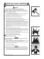 5
5
-
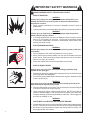 6
6
-
 7
7
-
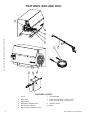 8
8
-
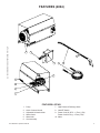 9
9
-
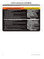 10
10
-
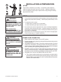 11
11
-
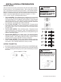 12
12
-
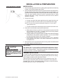 13
13
-
 14
14
-
 15
15
-
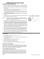 16
16
-
 17
17
-
 18
18
-
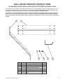 19
19
-
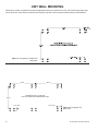 20
20
-
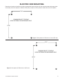 21
21
-
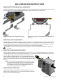 22
22
-
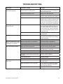 23
23
-
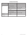 24
24
-
 25
25
-
 26
26
-
 27
27
-
 28
28
-
 29
29
-
 30
30
-
 31
31
-
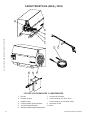 32
32
-
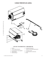 33
33
-
 34
34
-
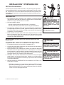 35
35
-
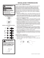 36
36
-
 37
37
-
 38
38
-
 39
39
-
 40
40
-
 41
41
-
 42
42
-
 43
43
-
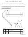 44
44
-
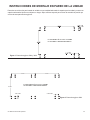 45
45
-
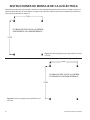 46
46
-
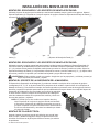 47
47
-
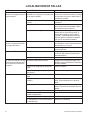 48
48
-
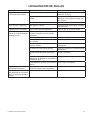 49
49
-
 50
50
-
 51
51
-
 52
52


Mi-T-M CAW Aluminum Series El manual del propietario
- Categoría
- Limpiadores de alta presión
- Tipo
- El manual del propietario
En otros idiomas
Documentos relacionados
-
 Mi-T-M JP Electric Series El manual del propietario
-
 Mi-T-M CW Electric Premium Series El manual del propietario
-
 Mi-T-M CW Premium Serie El manual del propietario
-
 Mi-T-M JP-SERIES Manual de usuario
-
 Mi-T-M CW-GASOLINE Manual de usuario
-
 Mi-T-M CW Gas & Diesel Premium Series El manual del propietario
-
 Mi-T-M HSE Series El manual del propietario
-
 Mi-T-M CWC DIESEL Series Manual de usuario
-
 Mi-T-M CD Series Gas El manual del propietario
-
 Mi-T-M HHD Series El manual del propietario


